US9089365B2 - Tissue fixation device - Google Patents
Tissue fixation deviceDownload PDFInfo
- Publication number
- US9089365B2 US9089365B2US13/472,297US201213472297AUS9089365B2US 9089365 B2US9089365 B2US 9089365B2US 201213472297 AUS201213472297 AUS 201213472297AUS 9089365 B2US9089365 B2US 9089365B2
- Authority
- US
- United States
- Prior art keywords
- fixation
- tissue
- fixation member
- members
- housing
- Prior art date
- Legal status (The legal status is an assumption and is not a legal conclusion. Google has not performed a legal analysis and makes no representation as to the accuracy of the status listed.)
- Active, expires
Links
Images


Classifications
- A—HUMAN NECESSITIES
- A61—MEDICAL OR VETERINARY SCIENCE; HYGIENE
- A61B—DIAGNOSIS; SURGERY; IDENTIFICATION
- A61B17/00—Surgical instruments, devices or methods
- A61B17/42—Gynaecological or obstetrical instruments or methods
- A61B17/4241—Instruments for manoeuvring or retracting the uterus, e.g. during laparoscopic surgery
- A—HUMAN NECESSITIES
- A61—MEDICAL OR VETERINARY SCIENCE; HYGIENE
- A61B—DIAGNOSIS; SURGERY; IDENTIFICATION
- A61B17/00—Surgical instruments, devices or methods
- A61B17/08—Wound clamps or clips, i.e. not or only partly penetrating the tissue ; Devices for bringing together the edges of a wound
- A—HUMAN NECESSITIES
- A61—MEDICAL OR VETERINARY SCIENCE; HYGIENE
- A61B—DIAGNOSIS; SURGERY; IDENTIFICATION
- A61B17/00—Surgical instruments, devices or methods
- A61B17/12—Surgical instruments, devices or methods for ligaturing or otherwise compressing tubular parts of the body, e.g. blood vessels or umbilical cord
- A61B17/122—Clamps or clips, e.g. for the umbilical cord
- A—HUMAN NECESSITIES
- A61—MEDICAL OR VETERINARY SCIENCE; HYGIENE
- A61B—DIAGNOSIS; SURGERY; IDENTIFICATION
- A61B17/00—Surgical instruments, devices or methods
- A61B17/42—Gynaecological or obstetrical instruments or methods
- A—HUMAN NECESSITIES
- A61—MEDICAL OR VETERINARY SCIENCE; HYGIENE
- A61B—DIAGNOSIS; SURGERY; IDENTIFICATION
- A61B17/00—Surgical instruments, devices or methods
- A61B17/42—Gynaecological or obstetrical instruments or methods
- A61B17/44—Obstetrical forceps
- A—HUMAN NECESSITIES
- A61—MEDICAL OR VETERINARY SCIENCE; HYGIENE
- A61B—DIAGNOSIS; SURGERY; IDENTIFICATION
- A61B17/00—Surgical instruments, devices or methods
- A61B17/42—Gynaecological or obstetrical instruments or methods
- A61B17/44—Obstetrical forceps
- A61B17/442—Obstetrical forceps without pivotal connections, e.g. using vacuum
- A—HUMAN NECESSITIES
- A61—MEDICAL OR VETERINARY SCIENCE; HYGIENE
- A61B—DIAGNOSIS; SURGERY; IDENTIFICATION
- A61B17/00—Surgical instruments, devices or methods
- A61B17/00234—Surgical instruments, devices or methods for minimally invasive surgery
- A61B2017/00349—Needle-like instruments having hook or barb-like gripping means, e.g. for grasping suture or tissue
- A—HUMAN NECESSITIES
- A61—MEDICAL OR VETERINARY SCIENCE; HYGIENE
- A61B—DIAGNOSIS; SURGERY; IDENTIFICATION
- A61B17/00—Surgical instruments, devices or methods
- A61B17/34—Trocars; Puncturing needles
- A61B2017/348—Means for supporting the trocar against the body or retaining the trocar inside the body
- A61B2017/3482—Means for supporting the trocar against the body or retaining the trocar inside the body inside
- A61B2017/3484—Anchoring means, e.g. spreading-out umbrella-like structure
- A61B2017/3488—Fixation to inner organ or inner body tissue
- A—HUMAN NECESSITIES
- A61—MEDICAL OR VETERINARY SCIENCE; HYGIENE
- A61B—DIAGNOSIS; SURGERY; IDENTIFICATION
- A61B17/00—Surgical instruments, devices or methods
- A61B17/42—Gynaecological or obstetrical instruments or methods
- A61B2017/4216—Operations on uterus, e.g. endometrium
- A—HUMAN NECESSITIES
- A61—MEDICAL OR VETERINARY SCIENCE; HYGIENE
- A61B—DIAGNOSIS; SURGERY; IDENTIFICATION
- A61B17/00—Surgical instruments, devices or methods
- A61B17/42—Gynaecological or obstetrical instruments or methods
- A61B2017/4216—Operations on uterus, e.g. endometrium
- A61B2017/4225—Cervix uteri
Definitions
- tissue fixation devicesinclude examples of tissue fixation devices.
- the tissue fixation devices described hereinmay be used with a uterine manipulator to grasp, retain and release cervical tissue. It will be appreciated that the disclosed embodiments may have applications outside of uterine manipulation, and may be used on other bodily tissues.
- Uterine manipulator devicescan be used to position and orient a uterus during surgery.
- U.S. Patent Application Publication No. US2012/0109147discloses an example uterine manipulator system.
- Typical uterine manipulator systemsconsist of a bell-housing or cup shaped member that fits around the cervix and a rod member that is inserted through the cervix and into the uterus.
- the bell housingcan be sized and shaped to compress the cervical tissue against the rod member to help the surgeon grasp the cervix and manipulate the position and orientation of the uterus.
- the bell housingcan also provide a cutting guide to facilitate incision placement, for example colpotomy incisions and incisions requiring a safe distance from the ureters and uterine arteries.
- incision placementfor example colpotomy incisions and incisions requiring a safe distance from the ureters and uterine arteries.
- the cervical tissue fixation within the bell housingis insufficient, a uniform colpotomy incision is difficult to achieve.
- the risk of damaging surrounding tissues, such as the ureters and uterine arterieswill increase if the tissue fixation is insufficient.
- the compressive forces imparted to the cervical tissue between the bell housing and the rod memberare usually not sufficient enough to tightly grasp the cervix and ensure safe incision placement.
- a balloonin combination with the rod member which can be inflated inside of the uterus to provide additional pressure on the cervical tissue between the balloon and the bell housing to force the cervical tissue down into the bell housing and increase the gripping force of the bell housing on the cervix.
- the internal balloonmay not create optimal tissue fixation, especially in patients with anatomical abnormalities, rigid tissues, scar tissue, and the like.
- the balloonmay leak or become accidentally “nicked” by other surgical instruments during the surgical procedure. This may result in loss of tissue fixation that can delay and complicate surgical incisions and/or removal of the uterus through the vagina in the case of a hysterectomy procedure.
- tissue fixationis typically not achieved with a balloon, as is evidenced by workarounds currently used by many surgeons. For example, surgeons are known to use adjunctive stitches through the cervix which are then tied to the instrument to increase tissue fixation. This workaround adds additional steps to the surgery and further complicates things by making it difficult to quickly remove the bell housing and/or uterine manipulator from the patient if an emergency situation arises, such as the need to defibrillate the patient's heart.
- tissue fixationwith or without a balloon, that will last throughout the entire surgical procedure and that will not be compromised by rigid tissue, anatomical abnormalities, scar tissue, cancerous tissue, or the like.
- tissue fixationclose to certain incision sites, such as the colpotomy incision site, to increase the control, placement and precision of the incision.
- tissue fixation mechanismemploys a simple actuation mechanism to quickly and easily engage and disengage the tissue fixation mechanism during surgery.
- An example of the present technology disclosed hereinincludes a tissue fixation assembly shaped to be attached to a uterine manipulator.
- the assemblyincludes a housing, a fixation member carriage with deployable fixation members, and a cap.
- the fixation member carriage and fixation membersare captured between the housing and the cap.
- a sutureis attached to the fixation member carriage and is actuatable to move the fixation member carriage to deploy or retract the fixation members.
- the assemblymay be inserted into a vagina and receive cervical tissue within the housing.
- the fixation membersmay then be deployed inwardly from the housing to grip the cervical tissue.
- the fixation membersmay also be locked in the deployed position to maintain the grip on the tissue.
- the fixation membersmay also be easily retracted to release the tissue and remove the device as needed.
- a sagittal planedivides a body into right and left portions.
- a mid-sagittal planedivides the body into equal right and left halves.
- a coronal planedivides a body into anterior and posterior portions.
- a transverse planedivides a body into superior and inferior portions.
- Anteriormeans toward the front of the body.
- Posteriormeans toward the back of the body.
- Superiormeans toward the head.
- Inferiormeans toward the feet.
- Medialmeans toward the midline of the body.
- Lateralmeans away from the midline of the body.
- Axialmeans toward a central axis of the body.
- Abaxialaway from a central axis of the body.
- Ipsilateralmeans on the same side of the body. Contralateral means on the opposite side of the body.
- FIG. 1is a perspective view of a tissue fixation device according to one example of the present disclosure having a housing, a cap, and deployable fixation members;
- FIG. 2is a side view of the tissue fixation device of FIG. 1 ;
- FIG. 3Ais a top view of the tissue fixation device of FIG. 1 with the fixation members in a retracted position
- FIG. 3Bis a top view of the tissue fixation device of FIG. 1 with the fixation members in a deployed position
- FIG. 4is an exploded view of the tissue fixation device of FIG. 1 ;
- FIG. 5is a top exploded view of the tissue fixation device of FIG. 1 ;
- FIG. 6is a bottom exploded view of the tissue fixation device of FIG. 1 ;
- FIG. 7Ais a top view of the housing and fixation member carriage assembly of the tissue fixation device of FIG. 1 with the fixation members in a retracted position and dashed lines indicating suture paths under the fixation member carriage assembly;
- FIG. 7Bis a top view of the housing and fixation member carriage assembly of the tissue fixation device of FIG. 1 with the fixation member in a deployed position;
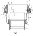
- FIG. 8is a side cross-sectional view of the tissue fixation device of FIG. 1 with the fixation members in a retracted position, taken along section line 8 - 8 in FIG. 7A ;
- FIG. 9is a perspective view of another tissue fixation device in accordance with the present disclosure with the tissue fixation members in the deployed configuration;
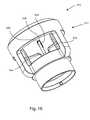
- FIG. 10is a perspective view of the tissue fixation device of FIG. 9 with the tissue fixation members in the retracted configuration
- FIG. 11is an exploded view of the tissue fixation device of FIG. 9 ;
- FIG. 12is a perspective view of another tissue fixation device in accordance with the present disclosure with the tissue fixation member in the deployed configuration;
- FIG. 13is a perspective view of the tissue fixation device of FIG. 12 with the tissue fixation member in the retracted configuration
- FIG. 14is a perspective view of another tissue fixation device in accordance with the present disclosure with the tissue fixation members in the deployed configuration;
- FIG. 15is a perspective view of the tissue fixation device of FIG. 14 with the tissue fixation members in the retracted configuration
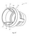
- FIG. 16is a perspective view of another tissue fixation device in accordance with the present disclosure with the tissue fixation members in the deployed configuration;
- FIG. 17is another perspective view of the tissue fixation device of FIG. 16 with the tissue fixation members in the deployed configuration
- FIG. 18is a perspective view of the tissue fixation device of FIG. 16 with the tissue fixation members in the retracted configuration
- FIG. 19is a perspective view of another tissue fixation device in accordance with the present disclosure with the tissue fixation members in the deployed configuration.
- FIG. 20is a perspective view of the tissue fixation device of FIG. 19 with the tissue fixation members in the retracted configuration.
- any of the devices described hereinmay be fabricated from metals, alloys, polymers, plastics, ceramics, glasses, composite materials, or combinations thereof, including but not limited to: titanium, titanium alloys, commercially pure titanium grade 2, ASTM F67, Nitinol, cobalt chrome, stainless steel, UHMWPE, PEEK, and biodegradable materials, among others. Different materials may be used within a single part.
- the devices disclosed hereinmay also encompass a variety of surface treatments or additives, including but not limited to: anti-microbial additives, analgesics, anti-inflammatories, etc.
- Any device disclosed hereinmay include a radiographic marker for imaging purposes. Any device disclosed herein may be color-coded or otherwise marked to make it easier for the surgeon to identify the type and size of the device.
- FIGS. 1-8illustrate one example of a tissue fixation device 10 .
- the tissue fixation device 10can include a housing 12 , a cap 14 , and a fixation member carriage assembly 16 (not visible in FIGS. 1 and 2 ) which carries at least one fixation member 18 .
- the fixation member 18may be a needle.
- the fixation member carriage assembly 16can be captured between the housing 12 and cap 14 , and may be rotatable within a track 26 formed in the housing 12 and/or the cap 14 .
- the cap 14may be integral with the housing 12 and not formed as a separate element.
- the cap 14 and housing 12may be referred to as a bell cap or a bell housing, as they may form a bell shape in some examples.
- the housing 12can have at least one enclosed section that completely encloses at least one planar surface.
- the at least one planar surfacecan be defined by a cross-sectional plane through the housing that results in a planar surface that is completely enclosed by an open portion of the housing.
- the planar surfaceis an empty plane that is completely bounded by the housing 12 .
- the housing 12may not have at least one enclosed section. In these examples there may be discontinuities or breaks in the housing (not shown) of any size or shape.
- the at least one fixation membercan be deployed away from an inner surface 42 of the housing and into the opening to grip tissue. The at least one fixation member can be also be retracted away from the opening toward an inner surface of the housing to release the tissue.
- the devicecan be actuable between a fixation member 18 retracted configuration, and a fixation member 18 deployed configuration. From the top or bottom perspective, the device can be radially symmetric.
- the embodiment shown in FIGS. 1-8includes three curved fixation members 18 . It will be appreciated that other embodiments may include more or fewer fixation members 18 .
- housing 12can be substantially circular or cylindrical in shape. However, the housing 12 can also be conical, frustoconical, funnel, ovoid, or polygonal in shape, or any combination of shapes thereof. The shape of the housing is not as important as the ability of the housing to enclose tissue to be grabbed by one or more fixation members, as will be apparent from the present disclosure.
- housing 12may include an attachment portion 20 which may be shaped to connect to a uterine manipulator (not shown).
- a plurality of struts 22can project superiorly from the attachment portion 20 and terminate at a carriage support 24 . Windows 23 may be interspersed between the struts 22 .
- the housingmay not include struts 22 or windows 23 .
- the carriage support 24can be ring-shaped, and include a carriage track 26 , which may be substantially circular.
- An outer rim 28can circumscribe the outer diameter of carriage track 26 , and a step 30 may be formed intermediate the track 26 and the outer rim 28 .
- One or more apertures 32can open through the carriage support 24 , and may pass through at least a portion of the outer rim 28 and step 30 .
- a housing inner wall 34can circumscribe the inner diameter of the carriage track 26 , and may include a plurality of discontinuations, or wall gaps 36 . At least one edge 38 of each wall gap 36 may be beveled. When operatively assembled, the fixation members 18 are deployable through the wall gaps 36 ; the beveled edges 38 may promote smooth deployment of the fixation members 18 and prevent the fixation members 18 from hanging up or being caught in the wall gaps 36 .
- Housing 12may be generally stepped in outer profile, wherein the carriage support 24 has the widest outer diameter, struts 22 form a circle of intermediate diameter, and attachment portion 20 has the narrowest outer diameter.
- the inner wall 34 , struts 22 , and attachment portion 20may surround and define a housing inner space 33 .
- a lengthwise central axis 35may extend through the housing inner space 33 , also defined by the inner wall 34 , struts 22 , and attachment portion 20 .
- the number and width of struts 22 and windows 23may vary, and in some embodiments the housing 12 may be formed as a continuous piece extending between the attachment portion 20 and the carriage support 24 , with no struts 22 or windows 23 present.
- the embodiment depicted in FIGS. 1-8is generally bell shaped; however in other embodiments the housing 12 and/or the device 10 may have a cylindrical shape and may include a tapered portion at either end. In other embodiments the device 10 may be cup or bowl shaped, or polygonal.
- Cap 14may have a ring-shape, and may include an outer side 40 opposite an inner side 42 .
- An outer surface 44 of the outer side 40may be positioned as an upper surface, and may include a plurality of steps, ridges and/or grooves which may facilitate gripping and manipulating the cap 14 .
- the inner side 42may have circular outer and inner diameters.
- a cap inner wall 43forms the inside diameter of the cap 14 , and may include a plurality of tabs 46 which project inferiorly from the inner wall 43 . Each tab 46 may include at least one beveled edge 48 .
- a cap outer wall 50may extend inferiorly, intermediate to and adjoining cap inner wall 43 and cap outer wall 50 and form a track cover 52 .
- a plurality of cap bosses 54can project inwardly from the cap outer wall 50 .
- Each cap boss 54may include a ramp feature 56 which urges the fixation member 18 inward as it is deployed.
- the cap 14can also have beveled edges 48 which can also help urge the fixation member 18 inward as it is deployed.
- Cap outer wall 50can include a plurality of recessed alcoves 58 which allow space for the curved fixation members 18 to be retained within the cap outer wall 50 when the fixation members 18 are in the retracted position.
- Housing 12 and cap 14may be formed of plastic, or other materials listed herein.
- Fixation carriage assembly 16can include a generally circular fixation carriage 60 .
- a plurality of mounting features 62can project superiorly from the fixation carriage 60 .
- Each mounting feature 62may include a recess 64 through which an opening 66 is formed. Openings 66 can be sized to allow passage of a suture 90 .
- Each mounting feature 62can further include a fixation member mount 68 .
- fixation member mount 68includes two pin holes 70 through which a mounting pin 72 passes.
- Fixation member carriage 60can have a first or superior side 74 and a second or inferior side 76 .
- a circular setback or groove 78can be formed on the inferior side 76 , and be sized to receive a suture.
- Each fixation member 18can be curved, rigid, and may terminate at a beveled point.
- the rigid fixation membersmay be formed of stainless steel, or other materials disclosed herein.
- Other embodimentsmay include flexible fixation members, which may be straight or curved, and may be made of Nitinol, for example.
- the fixation member curvaturemay be non-concentric with the curvature of the carriage track 26 , for example the fixation member curvature may have a smaller diameter than the diameter of the carriage track.
- Each fixation member 18may include a base portion 80 , a shaft 82 , and a point 84 , which may also be referred to as a tip.
- the fixationmay have an arch shape that lies substantially in a single plane in some examples, in other examples, the fixation member can be substantially straight. In yet further examples, the fixation member can have a curved shape in multiple planes or in an infinite number of planes.
- fixation member carriage assembly 16may be mounted in the upper portion of housing 12 , such that fixation member 60 is received in carriage track 26 .
- a line gap or suture gap 86may be formed between the groove 78 and outer rim 28 .
- a first line, or suture 90may be threaded through one opening 66 , along suture gap 86 in a first direction 100 and through one aperture 32 .
- a knot 92may be formed in the suture end remaining at opening 66 , the knot residing in recess 64 immediately adjacent opening 66 , and the knot preventing withdrawal of the first suture through the opening 66 .
- a second suture 94may be threaded through a second opening 66 , along suture gap 86 in a second direction 102 opposite the first direction, and through another aperture 32 .
- the second suture 94may also be knotted, forming knot 96 to prevent withdrawal.
- pulling on the first suture 90will pull the fixation member carriage assembly 16 in the first direction 100
- pulling on the second suturewill pull the fixation member carriage assembly 16 in the second, or opposite, direction 102 .
- the sutures 90 , 94may be replaced by another type of line, flexible member, rigid member, filament, braid, yarn, cable, wire, chain, strap, lacing, or the like.
- a single suturecan be used.
- a first end of the sutureis passed down through one opening 66 , along suture gap 86 and out one aperture 32 .
- the first endis then passed partially around the housing 12 , up into a second aperture 32 , along suture gap 86 and up through a second opening 66 .
- the sutureis knotted at both of the openings 66 , and a length of suture is left along the housing 12 , between the two openings 32 .
- the sutures or portions of the suturesmay be color-coded.
- the first suturemay be colored green and the second suture may be colored red; of course any color scheme may be used so long as the sutures are visually distinct.
- different portions of the one suturemay be color coded differently.
- the green colormay be used to indicate that pulling on the green suture (or green portion) will deploy the fixation members and the red color may be used to indicate that pulling on the red suture (or red portion) will retract the fixation members.
- portions of the suture(s)may be colored to a specific length in order to be used as visual indicators to show when the fixation members are fully deployed or retracted.
- the fixation membersare fully deployed.
- only one suture, or one portion thereof,may be colored, a second portion or a second suture retaining its natural color.
- one or more sliding tabs, levers or other actuation featuresmay be used instead of the sutures to move the fixation member carriage and/or deploy the one or more fixation members.
- the actuation featuresmay push, pull or otherwise urge movement of the fixation member carriage and/or fixation members.
- each fixation member 18is substantially contained in a fixation member retention space 88 bounded by fixation member carriage 60 , track cover 52 , housing inner wall 34 and cap outer wall 50 .
- each fixation member tip 84is adjacent to, but not extending beyond, a wall gap 36 .
- fixation member carriage assembly 16will be pulled along carriage track 26 in direction 100 .
- fixation member tips 84will encounter ramp features 56 of bosses 54 and be forced, or deflected, through the open portions of wall gaps 36 , thus being inwardly deployed.
- the deployment paths of fixation members 18may be coplanar in some embodiments, and the fixation members 18 may be deployed along a plane perpendicular to a lengthwise central axis 35 of the housing 12 .
- the fixation members 18may move up and/or down out of a plane perpendicular to a lengthwise central axis 35 of the housing 12 .
- the deployment paths of the fixation members 18may be parallel to the central housing axis, or at an acute angle to the axis; the paths themselves may be nonlinear, curved, helical, or the like.
- the fixation members 18may pierce tissue, such as cervical tissue, positioned in the housing inner space 33 . Deployment can stop when the fixation member bases 80 become wedged between housing inner wall 34 and cap ramp feature 56 . Another stop to the carriage motion may be formed when mounting feature 62 of the carriage assembly 16 encounters cap boss 54 . Because of the wedging engagement of the fixation member bases between the housing 12 and cap 14 , the deployed fixation members can be locked in the deployed configuration and remain deployed until they are intentionally retracted.
- the fixation member tips 84can be shaped similar to a hypodermic needle such that, minimum penetration force is needed to deploy the fixation members 18 into the tissue. Furthermore, in this example, when the three fixation members 18 are fully deployed, the fixation members 18 can engage with over 280 degrees of tissue, creating strong tissue fixation. Moreover, this embodiment allows the fixation members 18 to be close to the outer surface 44 of cap 14 which may serve as a cutting guide during colpotomy incisions. This allows the tissue fixation members to be less than about 0.25 inches from the cutting guide and the interiorly located fixation members 18 will not impinge on the cutting path. It will be appreciated that other size cutting guide tip designs can be made to adjust the distance and orientation of the cutting guide to achieve different incision placements as desired.
- fixation member bases 80will be disengaged from the inner wall 34 and ramp feature 56 , and fixation member carriage assembly 16 will be pulled in the opposite direction, or direction 102 .
- fixation member carriage assembly 16will be pulled in the opposite direction, or direction 102 .
- the inner curved side of the shaft 82 of each fixation memberwill be forced outward as it encounters inner wall 34 , and fixation members 18 will be retracted in through wall gaps 36 .
- FIGS. 9-20show alternative embodiments of tissue fixation devices.
- FIGS. 9-11show a tissue fixation device 110 having a housing 112 , a cap 115 , fixation member carriage 116 and at least two fixation members 114 which rotate into the deployed position in opposite directions.
- tissue fixation device 110has four fixation members 114 . Two of the fixation members rotate into the deployed position in the same direction and the other two fixation members rotate into the deployed position in the opposite direction.
- fixation members 114can be used in other embodiments without departing from the spirit or scope of the present disclosure. Similar to the example of FIGS.
- the fixation members 114can have beveled tips 118 which interact with ramp features (not shown) to force the fixation members inward toward the tissue as the fixation members 114 rotate into the deployed position, similar to other embodiments disclosed herein.
- the cap 115can also have beveled edges 156 which may also help urge the fixation member 18 inward as it is deployed.
- this tissue fixation devicecan be similar to that described above with reference to FIGS. 1-8 , except that multiple fixation member carriages 116 , 117 can be stacked on top of each other, with each of the fixation member carriages 116 , 117 being free to rotate in opposite directions.
- two fixation member carriages 116 , 117are used.
- more than two fixation member carriagescan be used. Actuation of the fixation members 114 into the deployed position can be accomplished by any mechanical means disclosed herein.
- a first suture (not shown) with one end split into two suture portionscan be used with one of the split ends connected to the first fixation member carriage 116 in a first direction and the other split end connected to the second fixation member carriage 117 in a second direction.
- a second suture (suture) with one end split into two suture portionscan be used to reverse the rotation of the two fixation member carriages with the split ends of the second suture connected to the fixation member carriages 116 , 117 in opposite directions relative to the split ends of the first suture.
- thiscauses the two fixation member carriages to rotate in opposite directions relative to pulling the first suture.
- FIGS. 12-13show a tissue fixation device 210 having a housing 212 , and a helical fixation member 214 which may be formed of a material such as Nitinol.
- FIG. 12shows the helical fixation member 214 in the deployed position
- FIG. 13shows the helical fixation member 214 in the retracted position.
- the helical fixation member 214can be engaged with a rotatable carriage member 216 .
- the helical fixation membercan have a sharp beveled tip 218 that is angled upward toward the inserted tissue to help draw the fixation member 214 into the tissue as the fixation member is rotated into the deployed position.
- tissuemay be received within housing 212 , and the helical fixation member 214 can be rotatably advanced into the tissue by rotating carriage member 216 to engage and hold the tissue relative to the housing 212 .
- helical fixation member 214advances along a deployment path which includes a rotational component and an axial component relative to the center housing axis.
- FIGS. 14-15show a tissue fixation device 310 having a housing 312 , and multiple helical fixation members 314 , 315 which may be formed of a material such as Nitinol.
- FIG. 14shows the helical fixation members 314 , 315 in the deployed position
- FIG. 15shows the helical fixation members 314 , 315 in the retracted position.
- the helical fixation members 314 , 315can be engaged with a rotatable carriage member 316 .
- the helical fixation members 314 , 315can have sharp beveled tips 318 that are angled upward toward the inserted tissue to help draw the fixation members 314 , 315 into the tissue as the fixation members 314 , 315 are rotated into the deployed position.
- the sharp beveled tips 318 of each of the helical fixation members 314 , 315can be positioned out of phase with each other by 180 degrees.
- tissuemay be received within housing 312 , and the helical fixation members 314 , 315 can be rotatably advanced into the tissue by rotating carriage member 316 to engage and hold the tissue relative to the housing 312 .
- helical fixation members 314 , 315advance along a deployment path which includes a rotational component and an axial component relative to the center housing axis. It will be appreciated that other embodiments may include more than two helical fixation members without departing from the spirit or scope of the present disclosure.
- FIGS. 16-18show a tissue fixation device 420 having a housing 422 and at least one curved fixation member 424 .
- there are three curved fixation members 424however, other embodiments may include more or fewer curved fixation members 424 .
- FIGS. 16 and 17show the curved fixation members 424 in the deployed position and FIG. 18 shows the curved fixation members 424 in the retracted position.
- the curved fixation members 424may be flexible, semi-flexible, or rigid.
- the curved fixation members 424may be advanced upward from the housing 422 , through tissue, and the tips 418 of the curved fixation members 424 may then be received in capture features 426 formed in the housing 422 to hold the tissue relative to the housing 422 .
- curved fixation members 424may reverse the deployment direction of the curved fixation members 424 .
- the curved fixation members 424may be advanced downward from the housing 422 , through tissue, such that the tips 418 of the curved fixation members 424 are received in capture features 426 formed in the lower portion of the housing 422 .
- the position of the apertures where the curved fixation members 424 exit the housing and the capture features 426are reversed.
- the curved fixation members 424may be advanced sideways from the housing 422 and into capture features 426 formed on the sides of the housing 422 such that the apertures where the curved fixation members 424 exit the housing and the capture features 426 lie in a plane substantially perpendicular to the lengthwise central axis of the housing 422 .
- FIGS. 19-20show a tissue fixation device 510 having a housing 522 and one or more fixation members 524 .
- FIG. 19shows the tissue fixation device 510 with the fixation members 524 in the deployed position.
- FIG. 20shows the tissue fixation device 510 with the fixation members 524 in the retracted configuration.
- the housingcan have angled ramps 528 formed near the beveled tips 518 of the fixation members 524 which force the fixation members toward the center of the tissue fixation device 510 and into the tissue as the fixation members 524 are moved into the deployed position.
- the fixation members 524can be moved between the deployed and retracted positions by means discussed herein including sutures, levers, sliding tabs, translating members or any other suitable mechanical means.
- Coupledis defined as connected, although not necessarily directly, and not necessarily mechanically.
- a step of a method or an element of a devicethat “comprises,” “has,” “includes” or “contains” one or more features, possesses those one or more features, but is not limited to possessing only those one or more features.
- a device or structure that is configured in a certain wayis configured in at least that way, but may also be configured in ways that are not listed.
- fixation members, needles, hooks or barbsmay be interchangeable in any of the embodiments set forth herein, as may the actuation means for deployment.
- the described embodimentsare to be considered in all respects only as illustrative and not restrictive.
- manufacturing, assembly methods, and materials described for one devicemay be used in the manufacture or assembly of another device.
- the scope of the inventionis, therefore, indicated by the appended claims rather than by the foregoing description. All changes which come within the meaning and range of equivalency of the claims are to be embraced within their scope.
Landscapes
- Health & Medical Sciences (AREA)
- Surgery (AREA)
- Life Sciences & Earth Sciences (AREA)
- Biomedical Technology (AREA)
- Medical Informatics (AREA)
- Veterinary Medicine (AREA)
- Public Health (AREA)
- Engineering & Computer Science (AREA)
- General Health & Medical Sciences (AREA)
- Heart & Thoracic Surgery (AREA)
- Nuclear Medicine, Radiotherapy & Molecular Imaging (AREA)
- Molecular Biology (AREA)
- Animal Behavior & Ethology (AREA)
- Gynecology & Obstetrics (AREA)
- Pregnancy & Childbirth (AREA)
- Reproductive Health (AREA)
- Surgical Instruments (AREA)
Abstract
Description
Claims (12)
Priority Applications (7)
| Application Number | Priority Date | Filing Date | Title |
|---|---|---|---|
| US13/472,297US9089365B2 (en) | 2012-04-26 | 2012-05-15 | Tissue fixation device |
| EP13721871.5AEP2840985A1 (en) | 2012-04-26 | 2013-04-26 | Tissue fixation system to grasp, retain and release tissue |
| JP2015509202AJP2015516226A (en) | 2012-04-26 | 2013-04-26 | Tissue fixation system for grasping, holding and releasing tissue |
| PCT/US2013/038512WO2013163609A1 (en) | 2012-04-26 | 2013-04-26 | Tissue fixation system to grasp, retain and release tissue |
| AU2013251378AAU2013251378A1 (en) | 2012-04-26 | 2013-04-26 | Tissue fixation system to grasp, retain and release tissue |
| US14/396,743US9610099B2 (en) | 2012-04-26 | 2013-04-26 | Tissue fixation device to grasp, retain and release tissue |
| CA2870458ACA2870458A1 (en) | 2012-04-26 | 2013-04-26 | Tissue fixation system to grasp, retain and release tissue |
Applications Claiming Priority (2)
| Application Number | Priority Date | Filing Date | Title |
|---|---|---|---|
| US201261638979P | 2012-04-26 | 2012-04-26 | |
| US13/472,297US9089365B2 (en) | 2012-04-26 | 2012-05-15 | Tissue fixation device |
Related Child Applications (1)
| Application Number | Title | Priority Date | Filing Date |
|---|---|---|---|
| US14/396,743ContinuationUS9610099B2 (en) | 2012-04-26 | 2013-04-26 | Tissue fixation device to grasp, retain and release tissue |
Publications (2)
| Publication Number | Publication Date |
|---|---|
| US20130289585A1 US20130289585A1 (en) | 2013-10-31 |
| US9089365B2true US9089365B2 (en) | 2015-07-28 |
Family
ID=49477934
Family Applications (2)
| Application Number | Title | Priority Date | Filing Date |
|---|---|---|---|
| US13/472,297Active2033-08-13US9089365B2 (en) | 2012-04-26 | 2012-05-15 | Tissue fixation device |
| US14/396,743Expired - Fee RelatedUS9610099B2 (en) | 2012-04-26 | 2013-04-26 | Tissue fixation device to grasp, retain and release tissue |
Family Applications After (1)
| Application Number | Title | Priority Date | Filing Date |
|---|---|---|---|
| US14/396,743Expired - Fee RelatedUS9610099B2 (en) | 2012-04-26 | 2013-04-26 | Tissue fixation device to grasp, retain and release tissue |
Country Status (1)
| Country | Link |
|---|---|
| US (2) | US9089365B2 (en) |
Cited By (10)
| Publication number | Priority date | Publication date | Assignee | Title |
|---|---|---|---|---|
| US20150105807A1 (en)* | 2012-04-26 | 2015-04-16 | Imds Llc | Tissue Fixation Device to Grasp, Retain and Release Tissue |
| USD742513S1 (en)* | 2014-06-18 | 2015-11-03 | Minimally Invasive Surgical Technologies, Inc. | Medical device |
| USD750779S1 (en)* | 2014-03-11 | 2016-03-01 | Prabhat Kumar Ahluwalia | Medical device |
| USD751198S1 (en)* | 2014-03-11 | 2016-03-08 | Prabhat Kumar Ahluwalia | Medical device |
| US9327097B2 (en) | 2013-03-12 | 2016-05-03 | Minimally Invasive Surgical Technologies, Inc | Uterine manipulator |
| USD755968S1 (en) | 2014-03-11 | 2016-05-10 | Prabhat Kumar Ahluwalia | Medical device |
| USD755966S1 (en)* | 2014-03-11 | 2016-05-10 | Prabhat Kumar Ahluwalia | Medical device |
| USD755967S1 (en)* | 2014-03-11 | 2016-05-10 | Prabhat Kumar Ahluwalia | Medical device |
| USD763445S1 (en) | 2014-03-11 | 2016-08-09 | Prabhat Kumar Ahluwalia | Medical device |
| USD763446S1 (en) | 2014-03-11 | 2016-08-09 | Prabhat Kumar Ahluwalia | Medical device |
Families Citing this family (5)
| Publication number | Priority date | Publication date | Assignee | Title |
|---|---|---|---|---|
| US20130023896A1 (en)* | 2011-07-20 | 2013-01-24 | Quimby Jennifer C | Surgical manipulation and occlusion device |
| CA2896382C (en)* | 2012-12-29 | 2017-06-13 | Suzhou Touchstone International Medical Science Co., Ltd. | Circular stapler and staple head assembly thereof |
| CN105105830B (en)* | 2015-09-29 | 2017-07-11 | 武汉市第一医院 | A kind of act palace cup with vagina suture |
| WO2019107439A1 (en)* | 2017-11-28 | 2019-06-06 | ニプロ株式会社 | Forceps |
| TR202014297A1 (en)* | 2020-09-09 | 2022-03-21 | Ondokuz Mayis Ueniversitesi | Uterine manipulator in minimally invasive surgery. |
Citations (85)
| Publication number | Priority date | Publication date | Assignee | Title |
|---|---|---|---|---|
| US75158A (en) | 1868-03-03 | Instrument foe making local | ||
| US496711A (en) | 1893-05-02 | Surgical instrument | ||
| US1400616A (en)* | 1921-01-10 | 1921-12-20 | Harvey B Mccrory | Abdominal retractor |
| US1462202A (en) | 1921-05-14 | 1923-07-17 | Earle B Hopper | Surgical instrument |
| US1991278A (en) | 1933-08-21 | 1935-02-12 | Joseph S Heintz | Cervical applicator |
| US2082782A (en) | 1935-10-03 | 1937-06-08 | Alfred G Allen | Vacuum tenaculum |
| US2108206A (en) | 1937-03-09 | 1938-02-15 | Lillian Pearl Mecker | Tenaculum |
| US2146472A (en) | 1937-03-01 | 1939-02-07 | Joseph S Heintz | Cervical applicator |
| US2482622A (en) | 1948-10-11 | 1949-09-20 | Kahn Edward | Self-retaining uterine cannula |
| US2536145A (en)* | 1946-09-19 | 1951-01-02 | Robert J Tapke | Surgical instrument |
| US2616421A (en) | 1950-05-18 | 1952-11-04 | Greenberg Emanuel Martin | Nozzle in the form of cervical caps |
| US3877433A (en) | 1973-11-05 | 1975-04-15 | Raymond Lee Organization Inc | Uterine elevator and manipulator |
| US4022208A (en) | 1974-07-25 | 1977-05-10 | Valtchev Konstantin L | Gynecologic instrument |
| US4085756A (en) | 1975-07-09 | 1978-04-25 | Kenneth Weaver | Method and apparatus for performing an electrosurgical procedure |
| US4997419A (en) | 1989-06-01 | 1991-03-05 | Edward Weck Incoporated | Laparoscopy cannula |
| US5059198A (en) | 1986-04-21 | 1991-10-22 | Gimpelson Richard J | Gynecological tenaculum |
| US5100382A (en) | 1988-10-24 | 1992-03-31 | Valtchev Konstantin L | Single channel balloon uterine injector |
| US5209754A (en) | 1992-04-02 | 1993-05-11 | Ahluwalia Prabhat K | Vaginal cervical retractor elevator |
| US5259836A (en) | 1987-11-30 | 1993-11-09 | Cook Group, Incorporated | Hysterography device and method |
| US5336228A (en) | 1992-01-14 | 1994-08-09 | Cholhan Hilary J | Cervical manipulator forceps |
| US5368598A (en) | 1991-04-19 | 1994-11-29 | Hasson; Harrith M. | Method of manipulating an uterus using a bendable manipulator |
| US5382252A (en) | 1994-03-24 | 1995-01-17 | Ethicon Endo-Surgery | Transvaginal uterine manipulator |
| US5409496A (en) | 1993-08-16 | 1995-04-25 | Blairden Precision Instruments | Uterine manipulator with locking mechanism |
| US5445643A (en) | 1993-03-09 | 1995-08-29 | Valtchev; Konstantin L. | Connection mechanisms for uterine mobilizer |
| US5464409A (en) | 1993-12-09 | 1995-11-07 | Mohajer; Reza S. | Uterine manipulator and protector |
| US5520698A (en) | 1994-10-19 | 1996-05-28 | Blairden Precision Instruments, Inc. | Simplified total laparoscopic hysterectomy method employing colpotomy incisions |
| US5540700A (en) | 1993-08-16 | 1996-07-30 | The Cooper Companies | Uterine manipulator |
| US5562680A (en) | 1992-01-03 | 1996-10-08 | Hasson; Harrith M. | Apparatus for assisting the performance of pelvic endoscopic procedures |
| US5578048A (en) | 1993-09-15 | 1996-11-26 | United States Surgical Corporation | Manipulator apparatus |
| GB2305609A (en) | 1995-09-29 | 1997-04-16 | Rocket Medical Plc | Intra-uterine device |
| US5643285A (en) | 1994-10-18 | 1997-07-01 | Blairden Precision Instruments, Inc. | Vaginal extender for colpotomy surgery |
| WO1997029889A1 (en) | 1996-02-19 | 1997-08-21 | Bergstroem Bo | Uterine manipulator |
| US5662676A (en) | 1992-06-24 | 1997-09-02 | K.U. Leuven Research & Development | Instrument set for laparoscopic hysterectomy |
| US5697937A (en) | 1996-02-23 | 1997-12-16 | Toma; Doina | Surgical clamp with manipulable guide means |
| US5746750A (en) | 1996-02-05 | 1998-05-05 | Richard Wolf Gmbh | Medical instrument for manipulation of the uterus |
| US5833611A (en) | 1997-07-17 | 1998-11-10 | Tepper; Ron | Real-time endovaginal sonography guidance of intra-uterine procedures |
| US5935098A (en) | 1996-12-23 | 1999-08-10 | Conceptus, Inc. | Apparatus and method for accessing and manipulating the uterus |
| US5980534A (en) | 1998-10-07 | 1999-11-09 | Gimpelson; Richard J. | Cervical clamp |
| US5993461A (en) | 1998-01-07 | 1999-11-30 | Abae; Mick | Laparoscopic instrument for manipulating the uterus during laparoscopic surgery |
| US6027518A (en) | 1995-05-30 | 2000-02-22 | Gaber; Benny | Seizing instrument |
| US20010021854A1 (en) | 2000-02-18 | 2001-09-13 | Jacques Donnez | Uterine manipulator |
| US6371973B1 (en) | 1999-08-04 | 2002-04-16 | Ron-Tech Medical Ltd. | Forceps useful for intrabody guiding and/or positioning of a medical instrument |
| US6423075B1 (en) | 2000-05-22 | 2002-07-23 | Jiwan Steven Singh | Uterine cannula and pelvic support for gynecological laparoscopy |
| US20030187334A1 (en) | 2002-02-11 | 2003-10-02 | Freespirit Unlimited Pty Ltd. | Uterine and vaginal vault manipulator |
| US6666873B1 (en) | 2002-08-08 | 2003-12-23 | Jack L. Cassell | Surgical coupler for joining tubular and hollow organs |
| US20040236349A1 (en) | 2003-01-22 | 2004-11-25 | Gellman Barry N. | Cervical tenaculum |
| US20050080437A1 (en) | 2003-10-08 | 2005-04-14 | Wright David Walter | Anastomosis apparatus and methods of deployment and manufacture |
| US20050113854A1 (en) | 2003-11-25 | 2005-05-26 | Uckele John E. | Cervical conization device |
| US20050125006A1 (en) | 2003-12-09 | 2005-06-09 | Nady Nady E. | Device for sealing a cervical canal |
| US20050251155A1 (en) | 2002-06-19 | 2005-11-10 | Orban Joseph P Iii | Method and apparatus for anastomosis |
| US20050277948A1 (en) | 2004-06-14 | 2005-12-15 | Leonard Cedars | Apparatus and methods for the administration of a cerclage |
| US20050283188A1 (en) | 1998-05-29 | 2005-12-22 | By-Pass, Inc. | Vascular closure device |
| US7175634B2 (en) | 2001-02-20 | 2007-02-13 | Marcus Vincent Van Heerden | Uterine manipulator device |
| US20070142844A1 (en) | 2005-12-20 | 2007-06-21 | Robert Kotmel | Cervical seal apparatus and method of sealing a cervix |
| US20070142860A1 (en) | 2005-12-20 | 2007-06-21 | Robert Kotmel | Cervical clamp apparatus and method of exerting a compressive force to a cervix |
| US20070173863A1 (en) | 2002-11-19 | 2007-07-26 | Vascular Control Systems, Inc. | Deployable constrictor for uterine artery occlusion |
| US20070260265A1 (en) | 2006-03-30 | 2007-11-08 | Christian Walter | Device for performing examinations and surgical interventions on the uterus |
| US7294139B1 (en) | 2002-07-26 | 2007-11-13 | C.M. Wright, Inc. | Controlled - motion endoscopic grasping instrument |
| US20070288051A1 (en) | 2006-04-17 | 2007-12-13 | Bruce Beyer | Fluid-filled cervical dilator |
| US7325546B2 (en) | 2003-11-20 | 2008-02-05 | Vascular Control Systems, Inc. | Uterine artery occlusion device with cervical receptacle |
| US7329265B2 (en) | 2003-01-30 | 2008-02-12 | Vascular Control Systems, Inc. | Uterine artery occlusion clamp |
| US20080058833A1 (en) | 2006-08-30 | 2008-03-06 | Syed Rizvi | Postpartum uterine manipulators and methods of use thereof |
| US20080109010A1 (en) | 2006-11-07 | 2008-05-08 | Femsuite, Llc | Apparatus for cervical manipulation and methods of use |
| US20080154244A1 (en) | 2006-12-21 | 2008-06-26 | Steven Jiwan Singh | Medical Instrument |
| US20080188863A1 (en) | 2007-02-07 | 2008-08-07 | Chu Michael S H | Uterine artery occlusion |
| WO2008136024A1 (en) | 2007-05-04 | 2008-11-13 | Sofar Spa | Uterine manipulator |
| US7479145B2 (en) | 2002-11-19 | 2009-01-20 | Vascular Control Systems, Inc. | Tenaculum-like device for intravaginal instrument delivery |
| US20090105728A1 (en)* | 2007-10-23 | 2009-04-23 | Minos Medical | Devices and methods for securing tissue |
| US20090182329A1 (en) | 2008-01-16 | 2009-07-16 | Tyco Healthcare Group Lp | Uterine Sealer |
| US20090318914A1 (en) | 2008-06-18 | 2009-12-24 | Utley David S | System and method for ablational treatment of uterine cervical neoplasia |
| US20100106163A1 (en) | 2008-10-24 | 2010-04-29 | Coopersurgical, Inc. | Uterine Manipulator Assemblies and Related Components and Methods |
| USD624647S1 (en) | 2009-07-14 | 2010-09-28 | Karl Storz Gmbh & Co. Kg | Working element for uterus manipulator |
| WO2010114577A1 (en) | 2009-03-30 | 2010-10-07 | Techdyne, Llc | Cervical stabilization device |
| US20100256623A1 (en) | 2009-04-02 | 2010-10-07 | Patrick Nicolas | Cervical Seal |
| US20100274260A1 (en) | 2007-12-12 | 2010-10-28 | Vectec | Single Use, Disposable Uterine Manipulator and Method of Use |
| US20100280524A1 (en) | 2007-02-16 | 2010-11-04 | Marco Antonio Lopez Zepeda | Uterine Manipulator for Complete Removal of Human Uteri |
| US20100305578A1 (en) | 2009-05-27 | 2010-12-02 | Coopersurgical, Inc. | Uterine Manipulators and Related Components and Methods |
| US20110106116A1 (en) | 2009-10-30 | 2011-05-05 | Wilson-Cook Medical Inc. | Apparatus and methods for achieving serosa-to-serosa closure of a bodily opening |
| US8082925B2 (en) | 1993-10-22 | 2011-12-27 | Gynetech Pty Ltd. | Transvaginal tube as an aid to laparoscopic surgery |
| USD653338S1 (en) | 2010-11-15 | 2012-01-31 | Karl Storz Gmbh & Co. Kg | Uterine manipulator |
| US20120029547A1 (en) | 2010-07-30 | 2012-02-02 | Ethicon Endo-Surgery, Inc. | Surgical circular stapler with tissue retention arrangements |
| US8162954B2 (en) | 2006-04-21 | 2012-04-24 | Samuel George | Uterine manipulators |
| US20120109014A1 (en) | 2010-11-01 | 2012-05-03 | Coopersurgical, Inc. | Cervical Sizing Devices and Related Kits and Methods |
| US20120109147A1 (en)* | 2010-11-01 | 2012-05-03 | Coopersurgical, Inc. | Uterine Manipulators and Related Components and Methods |
| US20130150877A1 (en) | 2010-08-11 | 2013-06-13 | Olympus Corporation | Treatment instrument |
Family Cites Families (2)
| Publication number | Priority date | Publication date | Assignee | Title |
|---|---|---|---|---|
| US8550088B1 (en) | 2008-08-15 | 2013-10-08 | Techdyne Llc | Cervical stabilization device |
| US9089365B2 (en)* | 2012-04-26 | 2015-07-28 | Imds Llc | Tissue fixation device |
- 2012
- 2012-05-15USUS13/472,297patent/US9089365B2/enactiveActive
- 2013
- 2013-04-26USUS14/396,743patent/US9610099B2/ennot_activeExpired - Fee Related
Patent Citations (86)
| Publication number | Priority date | Publication date | Assignee | Title |
|---|---|---|---|---|
| US75158A (en) | 1868-03-03 | Instrument foe making local | ||
| US496711A (en) | 1893-05-02 | Surgical instrument | ||
| US1400616A (en)* | 1921-01-10 | 1921-12-20 | Harvey B Mccrory | Abdominal retractor |
| US1462202A (en) | 1921-05-14 | 1923-07-17 | Earle B Hopper | Surgical instrument |
| US1991278A (en) | 1933-08-21 | 1935-02-12 | Joseph S Heintz | Cervical applicator |
| US2082782A (en) | 1935-10-03 | 1937-06-08 | Alfred G Allen | Vacuum tenaculum |
| US2146472A (en) | 1937-03-01 | 1939-02-07 | Joseph S Heintz | Cervical applicator |
| US2108206A (en) | 1937-03-09 | 1938-02-15 | Lillian Pearl Mecker | Tenaculum |
| US2536145A (en)* | 1946-09-19 | 1951-01-02 | Robert J Tapke | Surgical instrument |
| US2482622A (en) | 1948-10-11 | 1949-09-20 | Kahn Edward | Self-retaining uterine cannula |
| US2616421A (en) | 1950-05-18 | 1952-11-04 | Greenberg Emanuel Martin | Nozzle in the form of cervical caps |
| US3877433A (en) | 1973-11-05 | 1975-04-15 | Raymond Lee Organization Inc | Uterine elevator and manipulator |
| US4022208A (en) | 1974-07-25 | 1977-05-10 | Valtchev Konstantin L | Gynecologic instrument |
| US4085756A (en) | 1975-07-09 | 1978-04-25 | Kenneth Weaver | Method and apparatus for performing an electrosurgical procedure |
| US5059198A (en) | 1986-04-21 | 1991-10-22 | Gimpelson Richard J | Gynecological tenaculum |
| US5259836A (en) | 1987-11-30 | 1993-11-09 | Cook Group, Incorporated | Hysterography device and method |
| US5100382A (en) | 1988-10-24 | 1992-03-31 | Valtchev Konstantin L | Single channel balloon uterine injector |
| US4997419A (en) | 1989-06-01 | 1991-03-05 | Edward Weck Incoporated | Laparoscopy cannula |
| US5368598A (en) | 1991-04-19 | 1994-11-29 | Hasson; Harrith M. | Method of manipulating an uterus using a bendable manipulator |
| US5562680A (en) | 1992-01-03 | 1996-10-08 | Hasson; Harrith M. | Apparatus for assisting the performance of pelvic endoscopic procedures |
| US5336228A (en) | 1992-01-14 | 1994-08-09 | Cholhan Hilary J | Cervical manipulator forceps |
| US5209754A (en) | 1992-04-02 | 1993-05-11 | Ahluwalia Prabhat K | Vaginal cervical retractor elevator |
| US5662676A (en) | 1992-06-24 | 1997-09-02 | K.U. Leuven Research & Development | Instrument set for laparoscopic hysterectomy |
| US5562679A (en) | 1993-03-09 | 1996-10-08 | Valtchev; Konstantin L. | Collar system for uterine mobilizer |
| US5445643A (en) | 1993-03-09 | 1995-08-29 | Valtchev; Konstantin L. | Connection mechanisms for uterine mobilizer |
| US5540700A (en) | 1993-08-16 | 1996-07-30 | The Cooper Companies | Uterine manipulator |
| US5409496A (en) | 1993-08-16 | 1995-04-25 | Blairden Precision Instruments | Uterine manipulator with locking mechanism |
| US5578048A (en) | 1993-09-15 | 1996-11-26 | United States Surgical Corporation | Manipulator apparatus |
| US8082925B2 (en) | 1993-10-22 | 2011-12-27 | Gynetech Pty Ltd. | Transvaginal tube as an aid to laparoscopic surgery |
| US5464409A (en) | 1993-12-09 | 1995-11-07 | Mohajer; Reza S. | Uterine manipulator and protector |
| US5382252A (en) | 1994-03-24 | 1995-01-17 | Ethicon Endo-Surgery | Transvaginal uterine manipulator |
| US5643285A (en) | 1994-10-18 | 1997-07-01 | Blairden Precision Instruments, Inc. | Vaginal extender for colpotomy surgery |
| US5520698A (en) | 1994-10-19 | 1996-05-28 | Blairden Precision Instruments, Inc. | Simplified total laparoscopic hysterectomy method employing colpotomy incisions |
| US6027518A (en) | 1995-05-30 | 2000-02-22 | Gaber; Benny | Seizing instrument |
| GB2305609A (en) | 1995-09-29 | 1997-04-16 | Rocket Medical Plc | Intra-uterine device |
| US5746750A (en) | 1996-02-05 | 1998-05-05 | Richard Wolf Gmbh | Medical instrument for manipulation of the uterus |
| WO1997029889A1 (en) | 1996-02-19 | 1997-08-21 | Bergstroem Bo | Uterine manipulator |
| US5697937A (en) | 1996-02-23 | 1997-12-16 | Toma; Doina | Surgical clamp with manipulable guide means |
| US5935098A (en) | 1996-12-23 | 1999-08-10 | Conceptus, Inc. | Apparatus and method for accessing and manipulating the uterus |
| US5833611A (en) | 1997-07-17 | 1998-11-10 | Tepper; Ron | Real-time endovaginal sonography guidance of intra-uterine procedures |
| US5993461A (en) | 1998-01-07 | 1999-11-30 | Abae; Mick | Laparoscopic instrument for manipulating the uterus during laparoscopic surgery |
| US20050283188A1 (en) | 1998-05-29 | 2005-12-22 | By-Pass, Inc. | Vascular closure device |
| US5980534A (en) | 1998-10-07 | 1999-11-09 | Gimpelson; Richard J. | Cervical clamp |
| US6371973B1 (en) | 1999-08-04 | 2002-04-16 | Ron-Tech Medical Ltd. | Forceps useful for intrabody guiding and/or positioning of a medical instrument |
| US20010021854A1 (en) | 2000-02-18 | 2001-09-13 | Jacques Donnez | Uterine manipulator |
| US6423075B1 (en) | 2000-05-22 | 2002-07-23 | Jiwan Steven Singh | Uterine cannula and pelvic support for gynecological laparoscopy |
| US7175634B2 (en) | 2001-02-20 | 2007-02-13 | Marcus Vincent Van Heerden | Uterine manipulator device |
| US20030187334A1 (en) | 2002-02-11 | 2003-10-02 | Freespirit Unlimited Pty Ltd. | Uterine and vaginal vault manipulator |
| US20050251155A1 (en) | 2002-06-19 | 2005-11-10 | Orban Joseph P Iii | Method and apparatus for anastomosis |
| US7294139B1 (en) | 2002-07-26 | 2007-11-13 | C.M. Wright, Inc. | Controlled - motion endoscopic grasping instrument |
| US6666873B1 (en) | 2002-08-08 | 2003-12-23 | Jack L. Cassell | Surgical coupler for joining tubular and hollow organs |
| US20070173863A1 (en) | 2002-11-19 | 2007-07-26 | Vascular Control Systems, Inc. | Deployable constrictor for uterine artery occlusion |
| US7479145B2 (en) | 2002-11-19 | 2009-01-20 | Vascular Control Systems, Inc. | Tenaculum-like device for intravaginal instrument delivery |
| US20040236349A1 (en) | 2003-01-22 | 2004-11-25 | Gellman Barry N. | Cervical tenaculum |
| US7329265B2 (en) | 2003-01-30 | 2008-02-12 | Vascular Control Systems, Inc. | Uterine artery occlusion clamp |
| US20050080437A1 (en) | 2003-10-08 | 2005-04-14 | Wright David Walter | Anastomosis apparatus and methods of deployment and manufacture |
| US7325546B2 (en) | 2003-11-20 | 2008-02-05 | Vascular Control Systems, Inc. | Uterine artery occlusion device with cervical receptacle |
| US20050113854A1 (en) | 2003-11-25 | 2005-05-26 | Uckele John E. | Cervical conization device |
| US20050125006A1 (en) | 2003-12-09 | 2005-06-09 | Nady Nady E. | Device for sealing a cervical canal |
| US20050277948A1 (en) | 2004-06-14 | 2005-12-15 | Leonard Cedars | Apparatus and methods for the administration of a cerclage |
| US20070142860A1 (en) | 2005-12-20 | 2007-06-21 | Robert Kotmel | Cervical clamp apparatus and method of exerting a compressive force to a cervix |
| US20070142844A1 (en) | 2005-12-20 | 2007-06-21 | Robert Kotmel | Cervical seal apparatus and method of sealing a cervix |
| US20070260265A1 (en) | 2006-03-30 | 2007-11-08 | Christian Walter | Device for performing examinations and surgical interventions on the uterus |
| US20070288051A1 (en) | 2006-04-17 | 2007-12-13 | Bruce Beyer | Fluid-filled cervical dilator |
| US8162954B2 (en) | 2006-04-21 | 2012-04-24 | Samuel George | Uterine manipulators |
| US20080058833A1 (en) | 2006-08-30 | 2008-03-06 | Syed Rizvi | Postpartum uterine manipulators and methods of use thereof |
| US20080109010A1 (en) | 2006-11-07 | 2008-05-08 | Femsuite, Llc | Apparatus for cervical manipulation and methods of use |
| US20080154244A1 (en) | 2006-12-21 | 2008-06-26 | Steven Jiwan Singh | Medical Instrument |
| US20080188863A1 (en) | 2007-02-07 | 2008-08-07 | Chu Michael S H | Uterine artery occlusion |
| US20100280524A1 (en) | 2007-02-16 | 2010-11-04 | Marco Antonio Lopez Zepeda | Uterine Manipulator for Complete Removal of Human Uteri |
| WO2008136024A1 (en) | 2007-05-04 | 2008-11-13 | Sofar Spa | Uterine manipulator |
| US20090105728A1 (en)* | 2007-10-23 | 2009-04-23 | Minos Medical | Devices and methods for securing tissue |
| US20100274260A1 (en) | 2007-12-12 | 2010-10-28 | Vectec | Single Use, Disposable Uterine Manipulator and Method of Use |
| US20090182329A1 (en) | 2008-01-16 | 2009-07-16 | Tyco Healthcare Group Lp | Uterine Sealer |
| US20090318914A1 (en) | 2008-06-18 | 2009-12-24 | Utley David S | System and method for ablational treatment of uterine cervical neoplasia |
| US20100106163A1 (en) | 2008-10-24 | 2010-04-29 | Coopersurgical, Inc. | Uterine Manipulator Assemblies and Related Components and Methods |
| WO2010114577A1 (en) | 2009-03-30 | 2010-10-07 | Techdyne, Llc | Cervical stabilization device |
| US20100256623A1 (en) | 2009-04-02 | 2010-10-07 | Patrick Nicolas | Cervical Seal |
| US20100305578A1 (en) | 2009-05-27 | 2010-12-02 | Coopersurgical, Inc. | Uterine Manipulators and Related Components and Methods |
| USD624647S1 (en) | 2009-07-14 | 2010-09-28 | Karl Storz Gmbh & Co. Kg | Working element for uterus manipulator |
| US20110106116A1 (en) | 2009-10-30 | 2011-05-05 | Wilson-Cook Medical Inc. | Apparatus and methods for achieving serosa-to-serosa closure of a bodily opening |
| US20120029547A1 (en) | 2010-07-30 | 2012-02-02 | Ethicon Endo-Surgery, Inc. | Surgical circular stapler with tissue retention arrangements |
| US20130150877A1 (en) | 2010-08-11 | 2013-06-13 | Olympus Corporation | Treatment instrument |
| US20120109014A1 (en) | 2010-11-01 | 2012-05-03 | Coopersurgical, Inc. | Cervical Sizing Devices and Related Kits and Methods |
| US20120109147A1 (en)* | 2010-11-01 | 2012-05-03 | Coopersurgical, Inc. | Uterine Manipulators and Related Components and Methods |
| USD653338S1 (en) | 2010-11-15 | 2012-01-31 | Karl Storz Gmbh & Co. Kg | Uterine manipulator |
Cited By (12)
| Publication number | Priority date | Publication date | Assignee | Title |
|---|---|---|---|---|
| US20150105807A1 (en)* | 2012-04-26 | 2015-04-16 | Imds Llc | Tissue Fixation Device to Grasp, Retain and Release Tissue |
| US9610099B2 (en)* | 2012-04-26 | 2017-04-04 | Imds Llc | Tissue fixation device to grasp, retain and release tissue |
| US9327097B2 (en) | 2013-03-12 | 2016-05-03 | Minimally Invasive Surgical Technologies, Inc | Uterine manipulator |
| US9522252B2 (en) | 2013-03-12 | 2016-12-20 | Prabhat K. Ahluwalia | Uterine manipulator |
| USD750779S1 (en)* | 2014-03-11 | 2016-03-01 | Prabhat Kumar Ahluwalia | Medical device |
| USD751198S1 (en)* | 2014-03-11 | 2016-03-08 | Prabhat Kumar Ahluwalia | Medical device |
| USD755968S1 (en) | 2014-03-11 | 2016-05-10 | Prabhat Kumar Ahluwalia | Medical device |
| USD755966S1 (en)* | 2014-03-11 | 2016-05-10 | Prabhat Kumar Ahluwalia | Medical device |
| USD755967S1 (en)* | 2014-03-11 | 2016-05-10 | Prabhat Kumar Ahluwalia | Medical device |
| USD763445S1 (en) | 2014-03-11 | 2016-08-09 | Prabhat Kumar Ahluwalia | Medical device |
| USD763446S1 (en) | 2014-03-11 | 2016-08-09 | Prabhat Kumar Ahluwalia | Medical device |
| USD742513S1 (en)* | 2014-06-18 | 2015-11-03 | Minimally Invasive Surgical Technologies, Inc. | Medical device |
Also Published As
| Publication number | Publication date |
|---|---|
| US9610099B2 (en) | 2017-04-04 |
| US20130289585A1 (en) | 2013-10-31 |
| US20150105807A1 (en) | 2015-04-16 |
Similar Documents
| Publication | Publication Date | Title |
|---|---|---|
| US9089365B2 (en) | Tissue fixation device | |
| US9833260B2 (en) | Methods and instruments for forming a posterior knee portal and for inserting a cannula | |
| US5817111A (en) | Open loop suture snare | |
| US7674275B2 (en) | Suture anchor | |
| JP6346659B2 (en) | Surgical suturing device with lateral engagement | |
| KR101716520B1 (en) | Surgical device and method | |
| EP3222220B1 (en) | Suture thread for laparoscopic port site closing apparatus | |
| EP3222219A1 (en) | Laparoscopic port site closing apparatus | |
| JP6302842B2 (en) | Insertion device and insertion system for laparoscopic instruments | |
| EP3500185B1 (en) | Ferrule for use with a minimally invasive surgical suturing device | |
| EP2308378A2 (en) | Wound closure device including releasable barbs | |
| US11786249B2 (en) | Apparatus and method for delivering surgical tissue connectors into an abdominal cavity and removing the surgical tissue connectors from the abdominal cavity | |
| EP3192452B1 (en) | Medical needle | |
| EP2574307B1 (en) | Graft introducer | |
| US20140275752A1 (en) | Medical device and method for delivering an implant | |
| US20220000501A1 (en) | Passing tension member around tissue mass | |
| JP6737870B2 (en) | Bidirectional suturing device for medical use and its operating method | |
| CA2870458A1 (en) | Tissue fixation system to grasp, retain and release tissue | |
| CN111388034A (en) | Channel device for operation and trigger structure | |
| US7981125B1 (en) | Surgical knot pusher and cutter | |
| WO2018037953A1 (en) | Medical suturing needle | |
| WO2024133742A1 (en) | Minimally-invasive suturing device |
Legal Events
| Date | Code | Title | Description |
|---|---|---|---|
| AS | Assignment | Owner name:IMDS CORPORATION, UTAH Free format text:ASSIGNMENT OF ASSIGNORS INTEREST;ASSIGNOR:MIKENCLAUD LLC;REEL/FRAME:028354/0279 Effective date:20120611 Owner name:MIKENCLAUD LLC, IDAHO Free format text:ASSIGNMENT OF ASSIGNORS INTEREST;ASSIGNOR:JONES, MICHAEL, DR.;REEL/FRAME:028354/0177 Effective date:20120611 Owner name:IMDS CORPORATION, UTAH Free format text:ASSIGNMENT OF ASSIGNORS INTEREST;ASSIGNORS:PLOWMAN, NATHAN O.;ERICKSON, NATHAN;FAUTH, ANDREW R.;AND OTHERS;REEL/FRAME:028354/0067 Effective date:20120611 | |
| AS | Assignment | Owner name:MIKENCLAUD LLC, IDAHO Free format text:ASSIGNMENT OF ASSIGNORS INTEREST;ASSIGNOR:IMDS CORPORATION;REEL/FRAME:029740/0801 Effective date:20130131 | |
| AS | Assignment | Owner name:IMDS LLC, CALIFORNIA Free format text:CONVERSION OF ENTITY;ASSIGNOR:IMDS CORPORATION;REEL/FRAME:033453/0096 Effective date:20130903 | |
| AS | Assignment | Owner name:MIKENCLAUD LLC, IDAHO Free format text:ASSIGNMENT OF ASSIGNORS INTEREST;ASSIGNORS:JONES, MICHAEL;PLOWMAN, NATHAN O.;ERICKSON, NATHAN W.;AND OTHERS;SIGNING DATES FROM 20150212 TO 20150320;REEL/FRAME:035227/0755 Owner name:IMDS LLC, UTAH Free format text:ASSIGNMENT OF ASSIGNORS INTEREST;ASSIGNORS:JONES, MICHAEL;PLOWMAN, NATHAN O.;ERICKSON, NATHAN W.;AND OTHERS;SIGNING DATES FROM 20150212 TO 20150320;REEL/FRAME:035227/0755 | |
| STCF | Information on status: patent grant | Free format text:PATENTED CASE | |
| MAFP | Maintenance fee payment | Free format text:PAYMENT OF MAINTENANCE FEE, 4TH YR, SMALL ENTITY (ORIGINAL EVENT CODE: M2551); ENTITY STATUS OF PATENT OWNER: SMALL ENTITY Year of fee payment:4 | |
| MAFP | Maintenance fee payment | Free format text:PAYMENT OF MAINTENANCE FEE, 8TH YR, SMALL ENTITY (ORIGINAL EVENT CODE: M2552); ENTITY STATUS OF PATENT OWNER: SMALL ENTITY Year of fee payment:8 |