US9089327B2 - Surgical instrument with multi-phase trigger bias - Google Patents
Surgical instrument with multi-phase trigger biasDownload PDFInfo
- Publication number
- US9089327B2 US9089327B2US13/622,729US201213622729AUS9089327B2US 9089327 B2US9089327 B2US 9089327B2US 201213622729 AUS201213622729 AUS 201213622729AUS 9089327 B2US9089327 B2US 9089327B2
- Authority
- US
- United States
- Prior art keywords
- trigger
- end effector
- operable
- shaft
- return lever
- Prior art date
- Legal status (The legal status is an assumption and is not a legal conclusion. Google has not performed a legal analysis and makes no representation as to the accuracy of the status listed.)
- Active, expires
Links
Images


Classifications
- A—HUMAN NECESSITIES
- A61—MEDICAL OR VETERINARY SCIENCE; HYGIENE
- A61B—DIAGNOSIS; SURGERY; IDENTIFICATION
- A61B17/00—Surgical instruments, devices or methods
- A61B17/068—Surgical staplers, e.g. containing multiple staples or clamps
- A61B17/072—Surgical staplers, e.g. containing multiple staples or clamps for applying a row of staples in a single action, e.g. the staples being applied simultaneously
- A61B17/07207—Surgical staplers, e.g. containing multiple staples or clamps for applying a row of staples in a single action, e.g. the staples being applied simultaneously the staples being applied sequentially
- A—HUMAN NECESSITIES
- A61—MEDICAL OR VETERINARY SCIENCE; HYGIENE
- A61B—DIAGNOSIS; SURGERY; IDENTIFICATION
- A61B18/00—Surgical instruments, devices or methods for transferring non-mechanical forms of energy to or from the body
- A61B18/04—Surgical instruments, devices or methods for transferring non-mechanical forms of energy to or from the body by heating
- A61B18/12—Surgical instruments, devices or methods for transferring non-mechanical forms of energy to or from the body by heating by passing a current through the tissue to be heated, e.g. high-frequency current
- A61B18/14—Probes or electrodes therefor
- A61B18/1442—Probes having pivoting end effectors, e.g. forceps
- A61B18/1445—Probes having pivoting end effectors, e.g. forceps at the distal end of a shaft, e.g. forceps or scissors at the end of a rigid rod
- A61B18/1447—Probes having pivoting end effectors, e.g. forceps at the distal end of a shaft, e.g. forceps or scissors at the end of a rigid rod wherein sliding surfaces cause opening/closing of the end effectors
- A—HUMAN NECESSITIES
- A61—MEDICAL OR VETERINARY SCIENCE; HYGIENE
- A61B—DIAGNOSIS; SURGERY; IDENTIFICATION
- A61B5/00—Measuring for diagnostic purposes; Identification of persons
- A61B5/02—Detecting, measuring or recording for evaluating the cardiovascular system, e.g. pulse, heart rate, blood pressure or blood flow
- A61B5/0205—Simultaneously evaluating both cardiovascular conditions and different types of body conditions, e.g. heart and respiratory condition
- A—HUMAN NECESSITIES
- A61—MEDICAL OR VETERINARY SCIENCE; HYGIENE
- A61B—DIAGNOSIS; SURGERY; IDENTIFICATION
- A61B17/00—Surgical instruments, devices or methods
- A61B2017/00367—Details of actuation of instruments, e.g. relations between pushing buttons, or the like, and activation of the tool, working tip, or the like
- A61B2017/00371—Multiple actuation, e.g. pushing of two buttons, or two working tips becoming operational
- A61B2017/0038—Simultaneous actuation of two tools by pushing one button or the like
- A—HUMAN NECESSITIES
- A61—MEDICAL OR VETERINARY SCIENCE; HYGIENE
- A61B—DIAGNOSIS; SURGERY; IDENTIFICATION
- A61B17/00—Surgical instruments, devices or methods
- A61B17/28—Surgical forceps
- A61B17/29—Forceps for use in minimally invasive surgery
- A61B2017/2901—Details of shaft
- A61B2017/2908—Multiple segments connected by articulations
- A—HUMAN NECESSITIES
- A61—MEDICAL OR VETERINARY SCIENCE; HYGIENE
- A61B—DIAGNOSIS; SURGERY; IDENTIFICATION
- A61B17/00—Surgical instruments, devices or methods
- A61B17/28—Surgical forceps
- A61B17/29—Forceps for use in minimally invasive surgery
- A61B2017/2926—Details of heads or jaws
- A61B2017/2927—Details of heads or jaws the angular position of the head being adjustable with respect to the shaft
- A—HUMAN NECESSITIES
- A61—MEDICAL OR VETERINARY SCIENCE; HYGIENE
- A61B—DIAGNOSIS; SURGERY; IDENTIFICATION
- A61B17/00—Surgical instruments, devices or methods
- A61B17/28—Surgical forceps
- A61B17/29—Forceps for use in minimally invasive surgery
- A61B2017/2946—Locking means
- A—HUMAN NECESSITIES
- A61—MEDICAL OR VETERINARY SCIENCE; HYGIENE
- A61B—DIAGNOSIS; SURGERY; IDENTIFICATION
- A61B18/00—Surgical instruments, devices or methods for transferring non-mechanical forms of energy to or from the body
- A61B2018/00636—Sensing and controlling the application of energy
- A61B2018/00642—Sensing and controlling the application of energy with feedback, i.e. closed loop control
- A—HUMAN NECESSITIES
- A61—MEDICAL OR VETERINARY SCIENCE; HYGIENE
- A61B—DIAGNOSIS; SURGERY; IDENTIFICATION
- A61B18/00—Surgical instruments, devices or methods for transferring non-mechanical forms of energy to or from the body
- A61B2018/00636—Sensing and controlling the application of energy
- A61B2018/00666—Sensing and controlling the application of energy using a threshold value
- A61B2018/00678—Sensing and controlling the application of energy using a threshold value upper
- A—HUMAN NECESSITIES
- A61—MEDICAL OR VETERINARY SCIENCE; HYGIENE
- A61B—DIAGNOSIS; SURGERY; IDENTIFICATION
- A61B18/00—Surgical instruments, devices or methods for transferring non-mechanical forms of energy to or from the body
- A61B2018/00636—Sensing and controlling the application of energy
- A61B2018/00696—Controlled or regulated parameters
- A61B2018/00702—Power or energy
- A—HUMAN NECESSITIES
- A61—MEDICAL OR VETERINARY SCIENCE; HYGIENE
- A61B—DIAGNOSIS; SURGERY; IDENTIFICATION
- A61B18/00—Surgical instruments, devices or methods for transferring non-mechanical forms of energy to or from the body
- A61B2018/00636—Sensing and controlling the application of energy
- A61B2018/00696—Controlled or regulated parameters
- A61B2018/00755—Resistance or impedance
- A—HUMAN NECESSITIES
- A61—MEDICAL OR VETERINARY SCIENCE; HYGIENE
- A61B—DIAGNOSIS; SURGERY; IDENTIFICATION
- A61B18/00—Surgical instruments, devices or methods for transferring non-mechanical forms of energy to or from the body
- A61B2018/00636—Sensing and controlling the application of energy
- A61B2018/00696—Controlled or regulated parameters
- A61B2018/00767—Voltage
- A—HUMAN NECESSITIES
- A61—MEDICAL OR VETERINARY SCIENCE; HYGIENE
- A61B—DIAGNOSIS; SURGERY; IDENTIFICATION
- A61B18/00—Surgical instruments, devices or methods for transferring non-mechanical forms of energy to or from the body
- A61B2018/00636—Sensing and controlling the application of energy
- A61B2018/00773—Sensed parameters
- A61B2018/00791—Temperature
- A61B2018/00815—Temperature measured by a thermistor
- A—HUMAN NECESSITIES
- A61—MEDICAL OR VETERINARY SCIENCE; HYGIENE
- A61B—DIAGNOSIS; SURGERY; IDENTIFICATION
- A61B18/00—Surgical instruments, devices or methods for transferring non-mechanical forms of energy to or from the body
- A61B2018/00636—Sensing and controlling the application of energy
- A61B2018/00898—Alarms or notifications created in response to an abnormal condition
- A—HUMAN NECESSITIES
- A61—MEDICAL OR VETERINARY SCIENCE; HYGIENE
- A61B—DIAGNOSIS; SURGERY; IDENTIFICATION
- A61B18/00—Surgical instruments, devices or methods for transferring non-mechanical forms of energy to or from the body
- A61B18/04—Surgical instruments, devices or methods for transferring non-mechanical forms of energy to or from the body by heating
- A61B18/12—Surgical instruments, devices or methods for transferring non-mechanical forms of energy to or from the body by heating by passing a current through the tissue to be heated, e.g. high-frequency current
- A61B18/14—Probes or electrodes therefor
- A61B18/1442—Probes having pivoting end effectors, e.g. forceps
- A61B2018/1452—Probes having pivoting end effectors, e.g. forceps including means for cutting
- A61B2018/1455—Probes having pivoting end effectors, e.g. forceps including means for cutting having a moving blade for cutting tissue grasped by the jaws
Definitions
- a variety of surgical instrumentsinclude a tissue cutting element and one or more elements that transmit RF energy to tissue (e.g., to coagulate or seal the tissue).
- tissuee.g., to coagulate or seal the tissue
- ENSEAL® Tissue Sealing Deviceby Ethicon Endo-Surgery, Inc., of Cincinnati, Ohio.
- Further examples of such devices and related conceptsare disclosed in U.S. Pat. No. 6,500,176 entitled “Electrosurgical Systems and Techniques for Sealing Tissue,” issued Dec. 31, 2002, the disclosure of which is incorporated by reference herein; U.S. Pat. No. 7,112,201 entitled “Electrosurgical Instrument and Method of Use,” issued Sep. 26, 2006, the disclosure of which is incorporated by reference herein; U.S. Pat. No.
- a variety of surgical instrumentsinclude a shaft having an articulation section, providing enhanced positioning capabilities for an end effector that is located distal to the articulation section of the shaft.
- Examples of such devicesinclude various models of the ENDOPATH® endocutters by Ethicon Endo-Surgery, Inc., of Cincinnati, Ohio.
- Further examples of such devices and related conceptsare disclosed in U.S. Pat. No. 7,380,696, entitled “Articulating Surgical Stapling Instrument Incorporating a Two-Piece E-Beam Firing Mechanism,” issued Jun. 3, 2008, the disclosure of which is incorporated by reference herein; U.S. Pat. No. 7,404,508, entitled “Surgical Stapling and Cutting Device,” issued Jul.
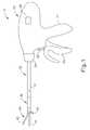
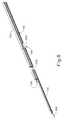
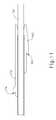
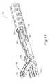
- FIG. 1depicts a side elevational view of an exemplary electrosurgical medical device
- FIG. 2depicts a perspective view of the end effector of the device of FIG. 1 , in an open configuration
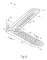
- FIG. 3depicts another perspective view of the end effector of the device of FIG. 1 , in an open configuration
- FIG. 4depicts a cross-sectional end view of the end effector of FIG. 2 taken along the line 4 - 4 of FIG. 3 , in a closed configuration and with the blade in a distal position;
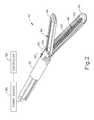
- FIG. 5depicts a perspective view of another exemplary electrosurgical medical device, with an articulation control knob
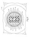
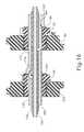
- FIG. 6depicts a cross-sectional end view of a shaft assembly of the device of FIG. 5 , taken along line 6 - 6 of FIG. 5 ;
- FIG. 7depicts a perspective view of components of the shaft assembly and end effector of the device of FIG. 5 ;
- FIG. 8depicts a perspective view of a support member of the shaft assembly of the device of FIG. 5 ;
- FIG. 9depicts a partial perspective view of articulation control components of the device of FIG. 5 , along one side of the support member;
- FIG. 10depicts a partial perspective view of articulation control components of the device of FIG. 5 , along another side of the support member;
- FIG. 11depicts a top plan view of the articulation control components of FIGS. 9-10 ;
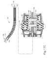
- FIG. 12depicts a partial perspective view of the articulation control components of FIG. 9 surrounded by a sheath;
- FIG. 13depicts a side elevational view of the handle assembly of the device of FIG. 5 , with a housing half removed;
- FIG. 14depicts a side elevational view of articulation control components of the handle assembly of FIG. 13 , with half of an articulation control knob body removed;
- FIG. 15depicts a perspective view of articulation control components of the handle assembly of FIG. 13 , coupled with the articulation control components of FIGS. 9-10 ;
- FIG. 16depicts a side cross-sectional view of the articulation control components of FIG. 15 , taken along line 16 - 16 of FIG. 15 ;
- FIG. 17Adepicts a partial cross-sectional view of articulation control components and the articulation section of the shaft of the device of FIG. 5 , with the articulation section in a substantially straight configuration;
- FIG. 17Bdepicts a partial cross-sectional view of the components of FIG. 17A , with the articulation section in a first stage of articulation;
- FIG. 17Cdepicts a partial cross-sectional view of the components of FIG. 17A , with the articulation section in a second stage of articulation;
- FIG. 18depicts an exploded perspective view of an exemplary firing beam assembly suited for incorporation in the device of FIG. 5 ;
- FIG. 19depicts a perspective view of a stop member of the firing beam assembly of FIG. 18 engaged with the distal end of the articulation section of the device of FIG. 5 ;
- FIG. 20depicts a perspective view of an exemplary alternative handle assembly, with a right housing half removed, suited for incorporation in the device of FIG. 5 ;
- FIG. 21Adepicts a side elevational view of the handle assembly of FIG. 20 , with a left housing half removed to reveal an exemplary return assist pivoting cam feature in a first position;
- FIG. 21Bdepicts a side elevational view of the components of FIG. 21A , with the return assist pivoting cam feature in a second position;
- FIG. 21Cdepicts a side elevational view of the components of FIG. 21A , with the return assist pivoting cam feature in a third position.
- FIGS. 1-4show an exemplary electrosurgical instrument ( 10 ) that is constructed and operable in accordance with at least some of the teachings of U.S. Pat. No. 6,500,176; U.S. Pat. No. 7,112,201; U.S. Pat. No. 7,125,409; U.S. Pat. No. 7,169,146; U.S. Pat. No. 7,186,253; U.S. Pat. No. 7,189,233; U.S. Pat. No. 7,220,951; U.S. Pat. No. 7,309,849; U.S. Pat. No. 7,311,709; U.S. Pat. No. 7,354,440; U.S. Pat. No. 7,381,209; U.S. Pub.
- electrosurgical instrument ( 10 )is operable to cut tissue and seal or weld tissue (e.g., a blood vessel, etc.) substantially simultaneously.
- electrosurgical instrument ( 10 )operates similar to an endocutter type of stapler, except that electrosurgical instrument ( 10 ) provides tissue welding through application of bipolar RF energy instead of providing lines of staples to join tissue.
- electrosurgical instrument ( 10 )may have various structural and functional similarities with the ENSEAL® Tissue Sealing Device by Ethicon Endo-Surgery, Inc., of Cincinnati, Ohio. Furthermore, electrosurgical instrument ( 10 ) may have various structural and functional similarities with the devices taught in any of the other references that are cited and incorporated by reference herein. To the extent that there is some degree of overlap between the teachings of the references cited herein, the ENSEAL® Tissue Sealing Device by Ethicon Endo-Surgery, Inc., of Cincinnati, Ohio, and the following teachings relating to electrosurgical instrument ( 10 ), there is no intent for any of the description herein to be presumed as admitted prior art. Several teachings below will in fact go beyond the scope of the teachings of the references cited herein and the ENSEAL® Tissue Sealing Device by Ethicon Endo-Surgery, Inc., of Cincinnati, Ohio.
- Electrosurgical instrument ( 10 ) of the present exampleincludes a handpiece ( 20 ), a shaft ( 30 ) extending distally from handpiece ( 20 ), and an end effector ( 40 ) disposed at a distal end of shaft ( 30 ).
- Handpiece ( 20 ) of the present exampleincludes a pistol grip ( 22 ), a pivoting trigger ( 24 ), an activation button ( 26 ), and an articulation control ( 28 ).
- Trigger ( 24 )is pivotable toward and away from pistol grip ( 22 ) to selectively actuate end effector ( 40 ) as will be described in greater detail below.
- Activation button ( 26 )is operable to selectively activate RF circuitry that is in communication with end effector ( 40 ), as will also be described in greater detail below.
- activation button ( 26 )also serves as a mechanical lockout against trigger ( 24 ), such that trigger ( 24 ) cannot be fully actuated unless button ( 26 ) is being pressed simultaneously. Examples of how such a lockout may be provided are disclosed in one or more of the references cited herein. It should be understood that pistol grip ( 22 ), trigger ( 24 ), and button ( 26 ) may be modified, substituted, supplemented, etc. in any suitable way, and that the descriptions of such components herein are merely illustrative. Articulation control ( 28 ) of the present example is operable to selectively control articulation section ( 36 ) of shaft ( 30 ), which will be described in greater detail below. Various examples of forms that articulation control ( 28 ) may take will also be described in greater detail below, while further examples will be apparent to those of ordinary skill in the art in view of the teachings herein.
- Shaft ( 30 ) of the present exampleincludes an outer sheath ( 32 ) and an articulation section ( 36 ).
- Articulation section ( 36 )is operable to selectively position end effector ( 40 ) at various angles relative to the longitudinal axis defined by sheath ( 32 ).
- end effector ( 40 )is operable to selectively position end effector ( 40 ) at various angles relative to the longitudinal axis defined by sheath ( 32 ).
- articulation section ( 36 ) and other components of shaft ( 30 )may take will be described in greater detail below, while further examples will be apparent to those of ordinary skill in the art in view of the teachings herein. For instance, it should be understood that various components that are operable to actuate articulation section ( 36 ) may extend through the interior of sheath ( 32 ).
- shaft ( 30 )is also rotatable about the longitudinal axis defined by sheath ( 32 ), relative to handpiece ( 20 ), via a knob ( 34 ). Such rotation may provide rotation of end effector ( 40 ) and shaft ( 30 ) unitarily.
- knob ( 34 )is operable to rotate end effector ( 40 ) without rotating any portion of shaft ( 30 ) that is proximal of articulation section ( 36 ).
- electrosurgical instrument ( 10 )may include one rotation control that provides rotatability of shaft ( 30 ) and end effector ( 40 ) as a single unit; and another rotation control that provides rotatability of end effector ( 40 ) without rotating any portion of shaft ( 30 ) that is proximal of articulation section ( 36 ).
- Other suitable rotation schemeswill be apparent to those of ordinary skill in the art in view of the teachings herein.
- rotatable featuresmay simply be omitted if desired.
- End effector ( 40 ) of the present examplecomprises a first jaw ( 42 ) and a second jaw ( 44 ).
- second jaw ( 44 )is substantially fixed relative to shaft ( 30 ); while first jaw ( 42 ) pivots relative to shaft ( 30 ), toward and away from second jaw ( 42 ).
- actuatorssuch as rods or cables, etc., may extend through sheath ( 32 ) and be joined with first jaw ( 42 ) at a pivotal coupling ( 43 ), such that longitudinal movement of the actuator rods/cables/etc. through shaft ( 30 ) provides pivoting of first jaw ( 42 ) relative to shaft ( 30 ) and relative to second jaw ( 44 ).
- jaws ( 42 , 44 )may instead have any other suitable kind of movement and may be actuated in any other suitable fashion.
- jaws ( 42 , 44 )may be actuated and thus closed by longitudinal translation of a firing beam ( 60 ), such that actuator rods/cables/etc. may simply be eliminated in some versions.
- first jaw ( 42 )defines a longitudinally extending elongate slot ( 46 ); while second jaw ( 44 ) also defines a longitudinally extending elongate slot ( 48 ).
- first electrode surface ( 50 )presents a first electrode surface ( 50 ); while the underside of second jaw ( 44 ) presents a second electrode surface ( 52 ).
- Electrode surfaces ( 50 , 52 )are in communication with an electrical source ( 80 ) via one or more conductors (not shown) that extend along the length of shaft ( 30 ).
- Electrical source ( 80 )is operable to deliver RF energy to first electrode surface ( 50 ) at a first polarity and to second electrode surface ( 52 ) at a second (opposite) polarity, such that RF current flows between electrode surfaces ( 50 , 52 ) and thereby through tissue captured between jaws ( 42 , 44 ).
- firing beam ( 60 )serves as an electrical conductor that cooperates with electrode surfaces ( 50 , 52 ) (e.g., as a ground return) for delivery of bipolar RF energy captured between jaws ( 42 , 44 ).
- Electrical source ( 80 )may be external to electrosurgical instrument ( 10 ) or may be integral with electrosurgical instrument ( 10 ) (e.g., in handpiece ( 20 ), etc.), as described in one or more references cited herein or otherwise.
- a controller ( 82 )regulates delivery of power from electrical source ( 80 ) to electrode surfaces ( 50 , 52 ). Controller ( 82 ) may also be external to electrosurgical instrument ( 10 ) or may be integral with electrosurgical instrument ( 10 ) (e.g., in handpiece ( 20 ), etc.), as described in one or more references cited herein or otherwise. It should also be understood that electrode surfaces ( 50 , 52 ) may be provided in a variety of alternative locations, configurations, and relationships.
- first jaw ( 42 )includes a longitudinally extending recess ( 58 ) adjacent to slot ( 46 ); while the upper side of second jaw ( 44 ) includes a longitudinally extending recess ( 58 ) adjacent to slot ( 48 ).
- FIG. 2shows the upper side of first jaw ( 42 ) including a plurality of teeth serrations ( 46 ). It should be understood that the lower side of second jaw ( 44 ) may include complementary serrations that nest with serrations ( 46 ), to enhance gripping of tissue captured between jaws ( 42 , 44 ) without necessarily tearing the tissue.
- serrations ( 46 ) in first jaw ( 42 )as mainly recesses; with serrations ( 48 ) in second jaw ( 44 ) as mainly protrusions.
- serrations ( 46 , 48 )may take any other suitable form or may be simply omitted altogether.
- serrations ( 46 , 48 )may be formed of an electrically non-conductive, or insulative, material, such as plastic, glass, and/or ceramic, for example, and may include a treatment such as polytetrafluoroethylene, a lubricant, or some other treatment to substantially prevent tissue from getting stuck to jaws ( 42 , 44 ).
- shaft ( 30 ) and end effector ( 40 )are sized and configured to fit through trocars having various inner diameters, such that electrosurgical instrument ( 10 ) is usable in minimally invasive surgery, though of course electrosurgical instrument ( 10 ) could also be used in open procedures if desired.
- shaft ( 30 ) and end effector ( 40 )may present an outer diameter of approximately 5 mm.
- shaft ( 30 ) and end effector ( 40 )may present any other suitable outer diameter (e.g., between approximately 2 mm and approximately 20 mm, etc.).
- either jaw ( 42 , 44 ) or both of jaws ( 42 , 44 )may include at least one port, passageway, conduit, and/or other feature that is operable to draw steam, smoke, and/or other gases/vapors/etc. from the surgical site.
- a featuremay be in communication with a source of suction, such as an external source or a source within handpiece ( 20 ), etc.
- end effector ( 40 )may include one or more tissue cooling features (not shown) that reduce the degree or extent of thermal spread caused by end effector ( 40 ) on adjacent tissue when electrode surfaces ( 50 , 52 ) are activated.
- tissue cooling featuresnot shown
- end effector ( 40 )includes one or more sensors (not shown) that are configured to sense a variety of parameters at end effector ( 40 ), including but not limited to temperature of adjacent tissue, electrical resistance or impedance of adjacent tissue, voltage across adjacent tissue, forces exerted on jaws ( 42 , 44 ) by adjacent tissue, etc.
- end effector ( 40 )may include one or more positive temperature coefficient (PTC) thermistor bodies ( 54 , 56 ) (e.g., PTC polymer, etc.), located adjacent to electrodes ( 50 , 52 ) and/or elsewhere.
- PTCpositive temperature coefficient
- Controller ( 82 )may process such data in a variety of ways.
- controller ( 82 )may modulate or otherwise change the RF energy being delivered to electrode surfaces ( 50 , 52 ), based at least in part on data acquired from one or more sensors at end effector ( 40 ).
- controller ( 82 )may alert the user to one or more conditions via an audio and/or visual feedback device (e.g., speaker, lights, display screen, etc.), based at least in part on data acquired from one or more sensors at end effector ( 40 ).
- an audio and/or visual feedback devicee.g., speaker, lights, display screen, etc.
- some kinds of sensorsneed not necessarily be in communication with controller ( 82 ), and may simply provide a purely localized effect at end effector ( 40 ).
- a PTC thermistor bodies ( 54 , 56 ) at end effector ( 40 )may automatically reduce the energy delivery at electrode surfaces ( 50 , 52 ) as the temperature of the tissue and/or end effector ( 40 ) increases, thereby reducing the likelihood of overheating.
- a PTC thermistor elementis in series with power source ( 80 ) and electrode surface ( 50 , 52 ); and the PTC thermistor provides an increased impedance (reducing flow of current) in response to temperatures exceeding a threshold.
- electrode surfaces ( 50 , 52 )may be used as sensors (e.g., to sense tissue impedance, etc.).
- electrosurgical instrument ( 10 )Various kinds of sensors that may be incorporated into electrosurgical instrument ( 10 ) will be apparent to those of ordinary skill in the art in view of the teachings herein. Similarly various things that can be done with data from sensors, by controller ( 82 ) or otherwise, will be apparent to those of ordinary skill in the art in view of the teachings herein. Other suitable variations for end effector ( 40 ) will also be apparent to those of ordinary skill in the art in view of the teachings herein.
- electrosurgical instrument ( 10 ) of the present exampleincludes a firing beam ( 60 ) that is longitudinally movable along part of the length of end effector ( 40 ).
- Firing beam ( 60 )is coaxially positioned within shaft ( 30 ), extends along the length of shaft ( 30 ), and translates longitudinally within shaft ( 30 ) (including articulation section ( 36 ) in the present example), though it should be understood that firing beam ( 60 ) and shaft ( 30 ) may have any other suitable relationship.
- Firing beam ( 60 )includes a sharp distal blade ( 64 ), an upper flange ( 62 ), and a lower flange ( 66 ). As best seen in FIG.
- distal blade ( 64 )extends through slots ( 46 , 48 ) of jaws ( 42 , 44 ), with upper flange ( 62 ) being located above jaw ( 44 ) in recess ( 59 ) and lower flange ( 66 ) being located below jaw ( 42 ) in recess ( 58 ).
- the configuration of distal blade ( 64 ) and flanges ( 62 , 66 )provides an “I-beam” type of cross section at the distal end of firing beam ( 60 ).
- flanges ( 62 , 66 )extend longitudinally only along a small portion of the length of firing beam ( 60 ) in the present example, it should be understood that flanges ( 62 , 66 ) may extend longitudinally along any suitable length of firing beam ( 60 ).
- flanges ( 62 , 66 )are positioned along the exterior of jaws ( 42 , 44 ), flanges ( 62 , 66 ) may alternatively be disposed in corresponding slots formed within jaws ( 42 , 44 ).
- each jaw ( 42 , 44 )may define a “T”-shaped slot, with parts of distal blade ( 64 ) being disposed in one vertical portion of each “T”-shaped slot and with flanges ( 62 , 66 ) being disposed in the horizontal portions of the “T”-shaped slots.
- flanges62 , 66
- Distal blade ( 64 )is substantially sharp, such that distal blade ( 64 ) will readily sever tissue that is captured between jaws ( 42 , 44 ). Distal blade ( 64 ) is also electrically grounded in the present example, providing a return path for RF energy as described elsewhere herein. In some other versions, distal blade ( 64 ) serves as an active electrode. In addition or in the alternative, distal blade ( 64 ) may be selectively energized with ultrasonic energy (e.g., harmonic vibrations at approximately 55.5 kHz, etc.).
- ultrasonic energye.g., harmonic vibrations at approximately 55.5 kHz, etc.
- the “I-beam” type of configuration of firing beam ( 60 )provides closure of jaws ( 42 , 44 ) as firing beam ( 60 ) is advanced distally.
- flange ( 62 )urges jaw ( 44 ) pivotally toward jaw ( 42 ) as firing beam ( 60 ) is advanced from a proximal position ( FIGS. 1-3 ) to a distal position ( FIG. 4 ), by bearing against recess ( 59 ) formed in jaw ( 44 ).
- This closing effect on jaws ( 42 , 44 ) by firing beam ( 60 )may occur before distal blade ( 64 ) reaches tissue captured between jaws ( 42 , 44 ).
- firing beam ( 60 )may reduce the force required to squeeze grip ( 24 ) to actuate firing beam ( 60 ) through a full firing stroke.
- firing beam ( 60 )may have already overcome an initial resistance required to substantially close jaws ( 42 , 44 ) on tissue before encountering resistance from severing the tissue captured between jaws ( 42 , 44 ).
- any other suitable stagingmay be provided.
- flange ( 62 )is configured to cam against a ramp feature at the proximal end of jaw ( 44 ) to open jaw ( 42 ) when firing beam ( 60 ) is retracted to a proximal position and to hold jaw ( 42 ) open when firing beam ( 60 ) remains at the proximal position.
- This camming capabilitymay facilitate use of end effector ( 40 ) to separate layers of tissue, to perform blunt dissections, etc., by forcing jaws ( 42 , 44 ) apart from a closed position.
- jaws ( 42 , 44 )are resiliently biased to an open position by a spring or other type of resilient feature.
- jaws ( 42 , 44 )close or open as firing beam ( 60 ) is translated in the present example
- other versionsmay provide independent movement of jaws ( 42 , 44 ) and firing beam ( 60 ).
- one or more cables, rods, beams, or other featuresmay extend through shaft ( 30 ) to selectively actuate jaws ( 42 , 44 ) independently of firing beam ( 60 ).
- Such jaw ( 42 , 44 ) actuation featuresmay be separately controlled by a dedicated feature of handpiece ( 20 ).
- jaw actuation featuresmay be controlled by trigger ( 24 ) in addition to having trigger ( 24 ) control firing beam ( 60 ).
- firing beam ( 60 )may be resiliently biased to a proximal position, such that firing beam ( 60 ) retracts proximally when a user relaxes their grip on trigger ( 24 ).
- end effector ( 40 )is inserted into a patient via a trocar.
- Articulation section ( 36 )is substantially straight when end effector ( 40 ) and part of shaft ( 30 ) are inserted through the trocar.
- Articulation control ( 28 )may then be manipulated to pivot or flex articulation section ( 36 ) of shaft ( 30 ) in order to position end effector ( 40 ) at a desired position and orientation relative to an anatomical structure within the patient.
- Two layers of tissue of the anatomical structureare then captured between jaws ( 42 , 44 ) by squeezing trigger ( 24 ) toward pistol grip ( 22 ).
- Such layers of tissuemay be part of the same natural lumen defining anatomical structure (e.g., blood vessel, portion of gastrointestinal tract, portion of reproductive system, etc.) in a patient.
- one tissue layermay comprise the top portion of a blood vessel while the other tissue layer may comprise the bottom portion of the blood vessel, along the same region of length of the blood vessel (e.g., such that the fluid path through the blood vessel before use of electrosurgical instrument ( 10 ) is perpendicular to the longitudinal axis defined by end effector ( 40 ), etc.).
- the lengths of jaws ( 42 , 44 )may be oriented perpendicular to (or at least generally transverse to) the length of the blood vessel.
- flanges ( 62 , 66 )cammingly act to pivot jaw ( 44 ) toward jaw ( 44 ) when firing beam ( 60 ) is actuated distally by squeezing trigger ( 24 ) toward pistol grip ( 22 ).
- firing beam ( 60 )continues to advance distally by the user squeezing trigger ( 24 ) toward pistol grip ( 22 ).
- distal blade ( 64 )simultaneously severs the clamped tissue layers, resulting in separated upper layer portions being apposed with respective separated lower layer portions. In some versions, this results in a blood vessel being cut in a direction that is generally transverse to the length of the blood vessel. It should be understood that the presence of flanges ( 62 , 66 ) immediately above and below jaws ( 42 , 44 ), respectively, may help keep jaws ( 42 , 44 ) in a closed and tightly clamping position.
- flanges ( 62 , 66 )may help maintain a significantly compressive force between jaws ( 42 , 44 ).
- electrode surfaces ( 50 , 52 )are activated with bipolar RF energy by the user depressing activation button ( 26 ).
- electrodes ( 50 , 52 )are selectively coupled with power source ( 80 ) (e.g., by the user depressing button ( 26 ), etc.) such that electrode surfaces ( 50 , 52 ) of jaws ( 42 , 44 ) are activated with a common first polarity while firing beam ( 60 ) is activated at a second polarity that is opposite to the first polarity.
- a bipolar RF currentflows between firing beam ( 60 ) and electrode surfaces ( 50 , 52 ) of jaws ( 42 , 44 ), through the compressed regions of severed tissue layer portions.
- electrode surface ( 50 )has one polarity while electrode surface ( 52 ) and firing beam ( 60 ) both have the other polarity.
- bipolar RF energy delivered by power source ( 80 )ultimately thermally welds the tissue layer portions on one side of firing beam ( 60 ) together and the tissue layer portions on the other side of firing beam ( 60 ) together.
- the heat generated by activated electrode surfaces ( 50 , 52 )can denature the collagen within the tissue layer portions and, in cooperation with clamping pressure provided by jaws ( 42 , 44 ), the denatured collagen can form a seal within the tissue layer portions.
- the severed ends of the natural lumen defining anatomical structureare hemostatically sealed shut, such that the severed ends will not leak bodily fluids.
- electrode surfaces ( 50 , 52 )may be activated with bipolar RF energy before firing beam ( 60 ) even begins to translate distally and thus before the tissue is even severed. For instance, such timing may be provided in versions where button ( 26 ) serves as a mechanical lockout relative to trigger ( 24 ) in addition to serving as a switch between power source ( 80 ) and electrode surfaces ( 50 , 52 ).
- electrosurgical instrument ( 10 )While several of the teachings below are described as variations to electrosurgical instrument ( 10 ), it should be understood that various teachings below may also be incorporated into various other types of devices. By way of example only, in addition to being readily incorporated into electrosurgical instrument ( 10 ), various teachings below may be readily incorporated into the devices taught in any of the references cited herein, other types of electrosurgical devices, surgical staplers, surgical clip appliers, and tissue graspers, among various other devices. Other suitable devices into which the following teachings may be incorporated will be apparent to those of ordinary skill in the art in view of the teachings herein.
- Articulation section ( 36 ) of shaft ( 30 )may take a variety of forms.
- articulation section ( 36 )may be configured in accordance with one or more teachings of U.S. Pub. No. 2012/0078247, entitled “Articulation Joint Features for Articulating Surgical Device,” published Mar. 29, 2012, the disclosure of which is incorporated by reference herein.
- articulation section ( 36 )may be configured in accordance with one or more teachings of U.S. Pub. No. 2012/0078248, entitled “Articulation Joint Features for Articulating Surgical Device,” published Mar. 29, 2012, the disclosure of which is incorporated by reference herein.
- articulation sectionmay be configured in accordance with the teachings of at least one other of the references cited herein.
- Various other suitable forms that articulation section ( 36 ) may takewill be apparent to those of ordinary skill in the art in view of the teachings herein.
- some versions of handpiece ( 20 )include an articulation control ( 28 ), which is operable to control articulation section ( 36 ) of shaft ( 30 ) to thereby selectively position end effector ( 40 ) at various angles relative to the longitudinal axis defined by sheath ( 32 ).
- articulation control ( 28 ) and other components of handpiece ( 20 )may take will be described in greater detail below, while further examples will be apparent to those of ordinary skill in the art in view of the teachings herein.
- some merely illustrative alternative examples of articulation control ( 28 )are disclosed in U.S. Pub. No. 2012/0078243, entitled “Control Features for Articulating Surgical Device,” published Mar. 29, 2012, the disclosure of which is incorporated by reference herein; and in U.S. Pub. No. 2012/0078244, entitled “Control Features for Articulating Surgical Device,” published Mar. 29, 2012, the disclosure of which is incorporated by reference herein.
- FIG. 5depicts an exemplary electrosurgical instrument ( 100 ) that includes a handpiece ( 120 ), a shaft ( 130 ) extending distally from handpiece ( 120 ), and an end effector ( 140 ) disposed at a distal end of shaft ( 130 ).
- Handpiece ( 120 ) of the present exampleincludes a pistol grip ( 122 ), a pivoting trigger ( 124 ), an activation button ( 126 ), and a rotary articulation knob ( 128 ).
- Trigger ( 124 )is pivotable toward and away from pistol grip ( 122 ) to selectively actuate end effector ( 140 ) as described above and as described in one or more reference cited herein.
- Activation button ( 126 )is operable to selectively activate RF circuitry that is in communication with end effector ( 140 ), as also described above and as described in one or more of the references cited herein.
- activation button ( 126 )also serves as a mechanical lockout against trigger ( 124 ), such that trigger ( 124 ) cannot be fully actuated unless button ( 126 ) is being pressed simultaneously. Examples of how such a lockout may be provided are disclosed in one or more of the references cited herein. It should be understood that pistol grip ( 122 ), trigger ( 124 ), and button ( 126 ) may be modified, substituted, supplemented, etc. in any suitable way, and that the descriptions of such components herein are merely illustrative. Articulation knob ( 128 ) of the present example is operable to selectively control articulation section ( 136 ) of shaft ( 130 ), as will be described in greater detail below.
- Shaft ( 130 ) of the present exampleincludes an outer sheath ( 132 ), an articulation section ( 136 ) at the distal end of sheath ( 132 ), and a cutting member driver tube ( 138 ) that is slidably and coaxially disposed within sheath ( 132 ).
- Cutting member driver tube ( 138 )is secured to a driver block ( 139 ), which is further secured to a cutting member ( 146 ) of end effector ( 140 ).
- Cutting member driver tube ( 138 )is movable longitudinally to drive driver block ( 139 ) longitudinally, to thereby move cutting member ( 146 ) longitudinally.
- Cutting member ( 146 )is essentially equivalent to firing beam ( 60 ) described above.
- the proximal portion ( 148 ) of end effector ( 140 )includes an insert (not shown) that defines a channel containing the part of cutting member ( 146 ) that extends through proximal portion ( 148 ). This channel is configured to permit cutting member ( 146 ) to readily translate relative to the insert, while also preventing cutting member ( 146 ) from buckling within the insert when cutting member ( 146 ) encounters a load during distal advancement of cutting member ( 146 ).
- driver tube ( 138 )is advanced distally by squeezing trigger ( 124 ) toward pistol grip ( 122 ); while driver tube ( 138 ) is retracted proximally by releasing trigger ( 124 ) and/or by actively moving trigger ( 124 ) away from pistol grip ( 122 ).
- a yoke ( 125 )couples trigger ( 124 ) with driver tube ( 138 ).
- cutting member ( 146 )may be moved in any other suitable fashion.
- Articulation section ( 136 ) of the present exampleis operable to selectively position end effector ( 140 ) at various angles relative to the longitudinal axis defined by sheath ( 132 ).
- end effector ( 140 )may be configured in accordance with end effector ( 40 ) described above, in accordance with the teachings of various references cited herein, and/or in any other suitable way as will be apparent to those of ordinary skill in the art in view of the teachings herein.
- shaft ( 130 )is also rotatable about the longitudinal axis defined by sheath ( 132 ), relative to handpiece ( 120 ), via a knob ( 134 ). Such rotation may provide rotation of end effector ( 140 ) and shaft ( 130 ) unitarily.
- knob ( 134 )is operable to rotate end effector ( 140 ) without rotating any portion of shaft ( 130 ) that is proximal of articulation section ( 136 ).
- electrosurgical instrument ( 100 )may include one rotation control that provides rotatability of shaft ( 130 ) and end effector ( 140 ) as a single unit; and another rotation control that provides rotatability of end effector ( 140 ) without rotating any portion of shaft ( 130 ) that is proximal of section ( 136 ).
- Other suitable rotation schemeswill be apparent to those of ordinary skill in the art in view of the teachings herein.
- rotatable featuresmay simply be omitted if desired.
- a rotation knob ( 134 ) and/or shaft ( 130 ) and/or end effector ( 140 )may include one or more markings facilitating visual identification of the rotational position. For instance, a user may correlate a marking on a rotation knob ( 134 ) with a corresponding marking on a shaft ( 130 ) and/or end effector ( 140 ) to better understand the orientation of such components with respect to the patient and instrument ( 100 ).
- FIGS. 6-12show various components of shaft ( 130 ) that provide control for articulation of articulation section ( 136 ).
- these componentsinclude a separator ( 150 ), a first articulation band ( 160 ) with an associated drive member ( 162 ), and a second articulation band ( 170 ) with an associated drive member ( 172 ).
- separator ( 150 )includes an upper lumen ( 151 ), a middle lumen ( 152 ), and a lower lumen ( 153 ).
- Separator ( 150 )also includes side recesses ( 154 ), a distal projection ( 156 ), and a gap ( 158 ).
- Separator ( 150 )is disposed within cutting member driver tube ( 138 ) and maintains a fixed longitudinal position during operation of instrument ( 100 ). Thus, separator ( 150 ) and outer sheath ( 132 ) remain stationary relative to each other and relative to handpiece ( 120 ); while cutting member driver tube ( 138 ) reciprocates relative to separator ( 150 ), outer sheath ( 132 ), and handpiece ( 120 ).
- Distal projection ( 156 )is configured to permit translation of driver block ( 139 ) substantially free from interference by distal projection ( 156 ) or by any other portion of separator ( 150 ).
- separator ( 150 )is formed as two pieces arranged in an end-to-end configuration, with a distal projection from the proximal piece helping to define gap ( 158 ).
- separator ( 150 )may alternatively be formed as a single piece or any other suitable number of pieces.
- gap ( 158 )may be formed as a cutout from a single piece of material.
- a wire ( 900 )extends through separator ( 150 ) to provide electrical communication to end effector ( 140 ).
- wire ( 900 )extends through middle lumen ( 152 ) from the proximal end of separator ( 150 ) until wire ( 900 ) reaches gap ( 158 ).
- wire ( 900 )transitions down to lower lumen ( 153 ), and extends through lower lumen ( 153 ) until reaching the distal end of separator ( 150 ).
- Wire ( 900 )then extends across articulation section ( 136 ) to end effector ( 140 ).
- Wire ( 900 )is thus operable to communicate power from a power source to end effector ( 140 ) in accordance with the teachings herein and in accordance with the teachings of various references cited herein.
- Distal projection ( 156 )protects wire ( 900 ) from driver block ( 139 ), such that driver block ( 139 ) is unable to contact wire ( 900 ) regardless of the longitudinal position of driver block ( 139 ) along distal projection ( 156 ).
- First articulation band ( 160 )is slidably disposed in one side recess ( 154 ) of separator ( 150 ) while second articulation band ( 170 ) is slidably disposed in the other side recess ( 154 ) of separator ( 150 ).
- side recesses ( 154 )include longitudinally extending grooves ( 155 ) that are configured to reduce the contact surface area with articulation bands ( 160 , 170 ), thereby reducing friction between separator ( 150 ) and articulation bands ( 160 , 170 ).
- Separator ( 150 )may also be formed of a low friction material and/or include a surface treatment to reduce friction.
- Articulation bands ( 160 , 170 )both extend longitudinally along the entire length of shaft ( 130 ), including through articulation section ( 136 ). As shown in FIG. 7 , the distal end ( 166 ) of first articulation band ( 160 ) is secured to one side of the proximal portion ( 148 ) of end effector ( 140 ) at an anchor point. The distal end ( 176 ) of second articulation band ( 170 ) is secured to the other side of proximal portion ( 148 ) of end effector ( 140 ) at an anchor point.
- rotary articulation knob ( 128 )is operable to selectively advance one articulation band ( 160 , 170 ) distally while simultaneously retracting the other articulation band ( 160 , 170 ) proximally, and vice-versa. It should be understood that this opposing translation will cause articulation section ( 136 ) to bend, thereby articulating end effector ( 140 ). In particular, end effector ( 140 ) will deflect toward whichever articulation band ( 160 , 170 ) is being retracted proximally; and away from whichever articulation band ( 160 , 170 ) is being advanced distally.
- drive member ( 162 )is unitarily secured to articulation band ( 160 ) and includes a notch ( 164 ) extending laterally inwardly.
- drive member ( 172 )is unitarily secured to articulation band ( 170 ) and includes a notch ( 174 ) extending laterally inwardly.
- drive members ( 162 , 164 )are spaced and configured such that notches ( 164 , 174 ) are at different longitudinal positions along the length of separator ( 150 ).
- the proximal portion of cutting member driver tube ( 138 )includes longitudinally extending slots ( 137 ).
- Drive members ( 162 , 172 )are slidably disposed in slots ( 137 ) and notches ( 164 , 174 ) are radially positioned outside the outer circumference of cutting member driver tube ( 138 ).
- Slots ( 137 )are configured to enable free translation of cutting member driver tube ( 138 ) relative to drive members ( 162 , 172 ), to thus enable free actuation of cutting member ( 164 ) regardless of the articulation state of articulation section ( 136 ).
- slots ( 137 )are configured to enable free translation of drive members ( 162 , 172 ) relative to cutting member driver tube ( 138 ), to thus enable free articulation of articulation section ( 136 ) regardless of the longitudinal position of cutting member ( 164 ).
- rotary articulation knob ( 128 )is coaxially positioned about the proximal portion of driver tube ( 138 ) and encompasses drive members ( 162 , 172 ). Articulation knob ( 128 ) is oriented perpendicular to the longitudinal axis defined by shaft ( 130 ) and is rotatable about the longitudinal axis defined by shaft ( 130 ).
- articulation knob ( 128 )As will be described in greater detail below, such rotation of articulation knob ( 128 ) will cause opposing translation of drive members ( 162 , 172 ), with the directions of such opposing translations depending on the direction in which articulation knob ( 128 ) is rotated, such that rotation of articulation knob ( 128 ) will articulate end effector ( 140 ).
- articulation knob ( 128 )includes a first internal threading ( 180 ) and a second internal threading ( 182 ). Threadings ( 181 , 182 ) have opposing pitch angles or orientations in this example.
- first lead screw ( 183 ) and a second lead screw ( 184 )are slidably disposed along a pair of pins ( 123 ), which are secured to housing ( 121 ).
- lead screws ( 183 , 184 )are operable to translate within housing ( 121 ) but are prevented from rotating within housing ( 121 ).
- First lead screw ( 183 )includes exterior threading ( 185 ) that is engaged with threading ( 181 ) of articulation knob ( 128 ); while second lead screw ( 184 ) includes exterior threading ( 186 ) that is engaged with threading ( 182 ) of articulation knob ( 128 ).
- the pitch angle of threading ( 185 )complements the pitch angle of threading ( 181 ); while the pitch angle of threading ( 186 ) complements the pitch angle of threading ( 182 ). It should therefore be understood that, due to the opposing pitch angles, rotation of knob ( 128 ) in a first direction will drive lead screw ( 183 ) distally while simultaneously driving lead screw ( 184 ) proximally; and rotation of knob in a second direction will drive lead screw ( 183 ) proximally while simultaneously driving lead screw ( 184 ) distally.
- the angles of threading ( 181 , 182 , 185 , 186 )are also configured such that articulation section ( 136 ) will be effectively locked in any given articulated position, such that transverse loads on end effector ( 140 ) will generally not bend articulation section ( 136 ), due to friction between threading ( 181 , 182 , 185 , 186 ).
- articulation section ( 136 )will only change its configuration when knob ( 128 ) is rotated. While the angles of threading may substantially prevent bending of articulation section ( 136 ) in response to transverse loads on end effector ( 140 ), the angles may still provide ready rotation of articulation knob ( 128 ) to translate lead screws ( 183 , 184 ).
- angles of threadingmay be approximately +/ ⁇ 2 degrees or approximately +/ ⁇ 3 degrees. Other suitable angles will be apparent to those of ordinary skill in the art in view of the teachings herein. It should also be understood that threading ( 181 , 182 , 185 , 186 ) may have a square or rectangular cross-section or any other suitable configuration.
- first tensioner gear ( 191 )is threadably engaged with first lead screw ( 183 ); while a second tensioner gear ( 192 ) is threadably engaged with second lead screw ( 184 ).
- first tensioner gear ( 191 ) relative to first lead screw ( 183 )may be adjusted by rotating first tensioner gear ( 191 ) relative to first lead screw ( 183 ); while the longitudinal position of second tensioner gear ( 192 ) relative to second lead screw ( 184 ) may be adjusted by rotating second tensioner gear ( 192 ) relative to second lead screw ( 184 ).
- first tensioner gear ( 191 )will translate unitarily with first lead screw ( 183 ); while second tensioner gear ( 192 ) will translate unitarily with second lead screw ( 184 ).
- First tensioner gear ( 191 )is also engaged with a washer ( 193 ), which is further engaged with notch ( 174 ) of drive member ( 172 ).
- the engagement between washer ( 193 ) and drive member ( 172 )is such that washer ( 193 ) and drive member ( 172 ) will translate together.
- washer ( 193 )is secured to tensioner gear ( 191 ) in such a manner that tensioner gear ( 191 ) both pulls washer ( 193 ) distally and pushes washer ( 193 ) proximally.
- first lead screw ( 183 )is operable to both push articulation band ( 170 ) distally and pull articulation band ( 170 ) proximally, depending on which direction knob ( 128 ) is rotated.
- tensioner gear ( 191 )merely abuts washer ( 193 ), such that tensioner gear ( 191 ) is operable to push washer ( 193 ) proximally but cannot pull washer ( 193 ) distally.
- first lead screw ( 183 )is operable to pull articulation band ( 170 ) proximally but cannot actively push articulation band ( 170 ) distally.
- first lead screw ( 183 )may simply pull tensioner gear ( 191 ) distally to enable articulation band ( 170 ), drive member ( 172 ), and washer ( 193 ) to be driven distally in response to proximal retraction of articulation band ( 160 ) as communicated through articulation section ( 136 ).
- drive member ( 172 ) and/or washer ( 193 )may be rotatable relative to tensioner gear ( 191 ), which may permit rotation of shaft ( 130 ) by knob ( 134 ).
- tensioner gear ( 191 )may be used to take out any tolerance gaps between drive member ( 172 ) and lead screw ( 183 ).
- second tensioner gear ( 192 )is engaged with a washer ( 194 ), which is further engaged with notch ( 164 ) of drive member ( 162 ).
- the engagement between washer ( 194 ) and drive member ( 162 )is such that washer ( 194 ) and drive member ( 162 ) will translate together.
- washer ( 194 )is secured to tensioner gear ( 192 ) in such a manner that tensioner gear ( 192 ) both pulls washer ( 194 ) distally and pushes washer ( 194 ) proximally.
- second lead screw ( 184 )is operable to both push articulation band ( 160 ) distally and pull articulation band ( 160 ) proximally, depending on which direction knob ( 128 ) is rotated.
- tensioner gear ( 192 )merely abuts washer ( 194 ), such that tensioner gear ( 192 ) is operable to push washer ( 194 ) proximally but cannot pull washer ( 194 ) distally.
- second lead screw ( 184 )is operable to pull articulation band ( 160 ) proximally but cannot actively push articulation band ( 160 ) distally.
- second lead screw ( 184 )may simply pull tensioner gear ( 192 ) distally to enable articulation band ( 160 ), drive member ( 162 ), and washer ( 194 ) to be driven distally in response to proximal retraction of articulation band ( 170 ) as communicated through articulation section ( 136 ).
- drive member ( 162 ) and/or washer ( 194 )may be rotatable relative to tensioner gear ( 192 ), which may permit rotation of shaft ( 130 ) by knob ( 134 ).
- tensioner gear ( 192 )may be used to take out any tolerance gaps between drive member ( 162 ) and lead screw ( 184 ).
- FIGS. 17A-17Cshow several of the above described components interacting to bend articulation section ( 136 ) to articulate end effector ( 140 ).
- articulation ( 136 )is in a substantially straight configuration.
- knob ( 128 )is rotated, which causes lead screw ( 183 ) to translate proximally and lead screw ( 184 ) to advance distally.
- This proximal translation of lead screw ( 183 )pulls articulation band ( 170 ) proximally, which causes articulation section ( 136 ) to start bending as shown in FIG. 17B .
- This bending of articulation section ( 136 )pulls articulation band ( 160 ) distally.
- knob ( 128 )includes a visual indicator that is associated with articulation section ( 136 ) being in a substantially straight configuration.
- a visual indicatormay align with a corresponding visual indicator on housing ( 121 ) of handpiece ( 120 ).
- the usermay observe such indicators to confirm whether articulation section ( 136 ) has in fact reached a substantially straight configuration.
- thismay be done right before instrument ( 100 ) is withdrawn from a trocar to reduce the likelihood of articulation section ( 136 ) snagging on a distal edge of the trocar.
- such indicatorsare merely optional.
- manufacturing inconsistenciesmay result in articulation bands ( 160 , 170 ) having slightly different lengths.
- Such inconsistenciesmay result in lost motion or slop in the operation of the articulation features of instrument ( 100 ).
- tensioner gears ( 191 , 192 )may be rotated relative to lead screws ( 183 , 184 ) to adjust the longitudinal position of drive members ( 162 , 172 ) relative to lead screws ( 183 , 184 ). For instance, if there is insufficient tension in articulation band ( 170 ), tensioner gear ( 191 ) may be rotated to drive washer ( 193 ) and drive member ( 172 ) proximally until articulation band ( 170 ) reaches a sufficient degree of tension.
- tensioner gear ( 192 )may be rotated to drive washer ( 195 ) and drive member ( 162 ) proximally until articulation band ( 160 ) reaches a sufficient degree of tension.
- Lead screws ( 183 , 184 )may remain substantially stationary during such adjustments.
- Articulation section ( 136 )may remain substantially straight during such adjustments and may even be held substantially straight during such adjustments.
- tensioner gears ( 191 , 192 )are rotated manually. In some other versions, tensioner gears ( 191 , 192 ) are rotated automatically by a rack or other gear.
- a control logicmay monitor the load on a motor that is being used to drive a calibrating rack or gear that is engaged with tensioner gear ( 191 , 192 ), and may automatically stop driving such a rack or gear when the load reaches a threshold associated with proper tensioning of band ( 160 , 170 ).
- tensioner gears ( 191 , 192 )may be rotated until such gaps are closed and sufficient contact is made between previously gapped components.
- tensioner gears ( 191 , 192 )may be automatically stopped when the proximal ends of bands ( 160 , 170 ) and/or drive members ( 162 , 172 ) reach a certain point.
- tensioner gears ( 191 , 192 )may be adjusted as a suitable way in which tensioner gears ( 191 , 192 ) may be adjusted will be apparent to those of ordinary skill in the art in view of the teachings herein. It should also be understood that tensioner gears ( 191 , 192 ) may be heat staked, glued, welded, or otherwise bonded to the respective lead screws ( 183 , 184 ) when the gaps between drive members ( 162 , 172 ) and their respective washers ( 193 , 194 ) reach zero. Such bonding may prevent subsequent movement of tensioner gears ( 191 , 192 ) relative to their respective lead screws ( 183 , 184 ).
- bands ( 160 , 170 )may be addressed at the distal ends of bands ( 160 , 170 ). For instance, before the distal ends of bands ( 160 , 170 ) are secured to the proximal portion ( 148 ) of end effector ( 140 ), articulation section ( 136 ) may be held in a straight configuration and bands ( 160 , 170 ) may be pulled distally to remove any slack in bands ( 160 , 170 ). With bands ( 160 , 170 ) both being in tension, bands ( 160 , 170 ) may then be welded or otherwise secured to proximal portion ( 148 ) of end effector ( 140 ).
- any of the versions of electrosurgical instrument ( 10 ) described hereinmay include various other features in addition to or in lieu of those described above. Several examples of such other features are described below, while other features will be apparent to those of ordinary skill in the art in view of the teachings herein.
- FIGS. 18-19show an exemplary alternative firing assembly ( 200 ) that may be readily incorporated into instrument ( 10 , 100 ) described above; and/or into various other kinds of instruments.
- Firing assembly ( 200 )will be discussed below in the context of instrument ( 100 ) only, though it should be understood that this context is being used merely as one of many possible examples.
- Firing assembly ( 200 ) of this examplecomprises a cutting member driver tube ( 238 ), a driver block ( 239 ), a cutting member driver beam ( 270 ), and a cutting member ( 260 ).
- Cutting member driver tube ( 238 )is substantially similar to cutting member driver tube ( 138 ) described above.
- Driver block ( 239 )is substantially similar to driver block ( 139 ) described above.
- Cutting member ( 260 )is substantially similar to cutting member ( 146 ) and firing beam ( 60 ) described above. All of the foregoing components of firing assembly ( 200 ) unitarily translate distally in response to trigger ( 324 ) being squeezed toward pistol grip ( 322 ); and unitarily translate proximally in response to trigger ( 324 ) pivoting away from pistol grip ( 322 ).
- driver tube ( 238 )is coupled with trigger ( 324 ) by a yoke ( 325 ), which converts pivotal movement of trigger ( 324 ) into linear movement of driver tube ( 238 ).
- the distal end of driver tube ( 238 )includes a longitudinally extending slot ( 242 ) that receives the proximal end ( 240 ) of driver block ( 239 ).
- Proximal end ( 240 )is fixedly secured in slot ( 242 ), such as by an interference fit and/or any other suitable type of relationship, etc.
- Proximal end ( 240 ) of driver block ( 239 )is tapered in this example, though it should be understood that other configurations could be used.
- the distal end ( 250 ) of driver block ( 239 )includes a pair of laterally projecting peg members ( 252 , 254 ). Peg members ( 252 , 254 ) are received in corresponding openings ( 272 , 274 ) of driver beam ( 270 ).
- Driver beam ( 270 )is longitudinally positioned to extend through articulation section ( 136 ). Driver beam ( 270 ) thus has sufficient flexibility and tensile strength to bend with articulation section ( 136 ) and still transfer linear actuating forces to cutting member ( 260 ) when articulation section ( 236 ) is in a bent configuration.
- Driver beam ( 270 )includes a distal projection ( 276 ) that is received in a proximal recess ( 282 ) of cutting member ( 260 ).
- driver tube ( 238 ), driver block ( 239 ), driver beam ( 270 ), and cutting member ( 260 )are merely exemplary.
- Various other suitable structures and techniques for coupling these components togetherwill be apparent to those of ordinary skill in the art in view of the teachings herein.
- Cutting member ( 260 ) of the present exampleincludes an upper flange ( 262 ), a lower flange ( 266 ), and a distal blade ( 264 ).
- cutting member ( 260 )is substantially more rigid than driver beam ( 270 ).
- Flanges ( 262 , 266 ) and blade ( 264 ) of the present exampleare substantially the same as flanges ( 62 , 66 ) and blade ( 64 ) described above.
- flanges ( 62 , 66 )are operable to actuate jaws ( 142 , 144 ) of end effector while distal blade ( 264 ) is operable to sever tissue captured between jaws ( 142 , 144 ).
- Cutting member ( 260 ) of this examplealso includes a stop member ( 280 ).
- Stop member ( 280 )comprises a block integrally positioned on the upper edge of cutting member ( 260 ), located proximal to upper flange ( 262 ).
- stop member ( 280 )is configured to engage a distal face ( 286 ) presented by articulation section ( 136 ) when firing assembly ( 200 ) is in a proximal position, with the jaws ( 142 , 144 ) of end effector ( 140 ) in a fully open configuration.
- stop member ( 280 )may restrict the proximal positioning of cutting member ( 260 ), to thereby ensure a consistent positioning of flanges ( 262 , 266 ) relative to jaws ( 142 , 144 ) when firing assembly ( 200 ) is in a proximal position. This may prevent flanges ( 262 , 266 ) from fully disengaging jaws ( 142 , 144 ) when firing assembly ( 200 ) is in a proximal position.
- a distal sheath section(not shown) encompasses the assembly that extends between articulation section ( 136 ) and end effector ( 140 ). This distal sheath section is omitted from FIG. 19 in order to show the position of stop member ( 280 ).
- driver tube ( 238 ) and a proximal portion of driver beam ( 270 )are encompassed within a sheath ( 232 ), similar to sheath ( 132 ) described above.
- Sheath ( 232 ), firing assembly ( 200 ), articulation section ( 136 ), and end effector ( 140 )are all rotatable about the longitudinal axis defined by sheath ( 232 ), relative to handpiece ( 320 ), via a knob ( 334 ).
- Knob ( 334 ), sheath ( 132 ), articulation section ( 136 ), end effector ( 140 ), and/or some other componentmay include a visible marking to enable a surgeon to readily ascertain the angular position of end effector ( 140 ) about the longitudinal axis defined by sheath ( 232 ).
- one or more detent features and/or other kind of feature(s)may provide an audible and/or tactile indication of the angular position of end effector ( 140 ) about the longitudinal axis defined by sheath ( 232 ).
- some versionsmay also simply lack rotatability altogether, such that knob ( 334 ) may be omitted.
- a trigger ( 24 , 124 )may be squeezed toward a pistol grip ( 22 , 124 ) to actuate an end effector ( 40 , 140 ).
- a spring(not shown) resiliently biases trigger ( 24 , 124 ) away from pistol grip ( 22 , 124 ).
- the usermay simply release trigger ( 24 , 124 ), and the spring may then return trigger ( 24 , 124 ) to a “home” position where it is pivoted away from pistol grip ( 22 , 124 ).
- friction through articulation section ( 36 , 136 )may provide substantial resistance to trigger ( 24 , 124 ) returning to the home position, particularly when articulation section ( 36 , 136 ) is in a bent configuration. This resistance may be most pronounced when trigger ( 24 , 124 ) is near the end of its return stroke. It may therefore be desirable in some instances to provide additional mechanical assistance to trigger ( 24 , 124 ) as it approaches the end of its return stroke. It may also be desirable to provide a substantially constant amount of resistance to the user squeezing trigger ( 24 , 124 ) during the entire firing stroke, such that the resistance forces encountered by the user are not substantially greater during certain stages of the firing stroke.
- FIGS. 20-21Cshow exemplary components that may be used to assist the return stroke of trigger ( 24 , 124 ) from an actuated position (e.g., where trigger ( 24 , 124 ) is pivoted to pistol grip ( 22 , 124 )) to a home position (e.g., where trigger ( 24 , 124 ) is pivoted away from pistol grip ( 22 , 124 )).
- These componentsmay also provide a substantially constant amount of resistance to the user squeezing trigger ( 24 , 124 ) during the entire firing stroke (e.g., from the home position of FIG. 21A to the actuated position of FIG. 21C ).
- a trigger ( 324 )is pivotally secured to a housing ( 323 ) of a handpiece at a pivot point ( 327 ) by a pivot arm ( 340 ).
- Pivot arm ( 340 )is coupled with yoke ( 325 ) by a linkage ( 342 ).
- a pin ( 341 ) that is integral with pivot arm ( 340 )is disposed in a slot ( 343 ) of linkage ( 342 ).
- Linkage ( 342 )is pivotable about a pivot point ( 345 ) that is fixed relative to housing ( 323 ).
- pivoting of trigger ( 324 )is transmitted to yoke ( 325 ) by linkage ( 342 ) to translate yoke ( 325 ) longitudinally.
- this translation of yoke ( 325 )translates driver tube ( 238 ) to translate cutting member ( 260 ) longitudinally.
- a coil spring ( 400 )is disposed between pivot arm ( 340 ) and housing ( 323 ), and is configured to resiliently bias trigger ( 324 ) to the home position shown in FIG. 21A .
- Trigger ( 324 )also includes a unitary, proximally extending cam arm ( 350 ) that engages a cam lever ( 500 ) as will be described in greater detail below.
- Cam arm ( 350 )includes a tip ( 352 ), a first underside surface ( 354 ), and a second underside surface ( 356 ).
- Cam arm ( 350 )provides a generally rounded transition from tip ( 352 ) to first underside surface ( 354 ).
- Cam arm ( 350 )also provides a sloped or angled transition from first underside surface ( 354 ) to second underside surface ( 356 ).
- Surfaces ( 354 , 356 )are generally parallel to each other but are offset relative to each other as best seen in FIGS. 21A-21C . The offset of surfaces ( 354 , 356 ) provides staged engagement with cam lever ( 500 ) during actuation of trigger ( 324 ).
- Cam lever ( 500 )is pivotally secured to housing ( 323 ) by a post ( 502 ).
- a torsion spring ( 600 )is coaxially disposed about post ( 502 ) and resiliently biases cam lever ( 500 ) to the rotational position shown in FIG. 21A .
- torsion spring ( 600 )includes a first free end ( 602 ) that engages a boss (not shown) of housing ( 323 ), thereby providing a mechanical ground for torsion spring ( 600 ).
- First free end ( 602 )is substantially straight and extends generally parallel to the longitudinal axis defined by pistol grip ( 322 ). As shown in FIGS.
- torsion spring ( 600 )also includes a second free end ( 604 ) that is disposed in a slot ( 504 ) of cam lever ( 500 ).
- Second free end ( 604 )is generally bent and extends transversely relative to the longitudinal axis defined by pistol grip ( 322 ).
- a brace ( 550 )is secured to post ( 502 ) and another post ( 552 ). Brace ( 550 ) simply retains cam lever ( 500 ) relative to housing ( 323 ), such as to prevent cam lever ( 500 ) from disengaging post ( 502 ) during assembly. Brace ( 550 ) does not affect rotation of cam lever ( 500 ) relative to housing ( 323 ).
- torsion spring ( 600 )is pre-loaded in the configuration shown in FIG. 21A , urging cam lever ( 500 ) counterclockwise.
- Cam lever ( 500 )includes a grounding arm ( 506 ) that engages and bears against a boss (not shown) of housing ( 323 ) when cam lever ( 500 ) is in the position shown in FIG. 21A .
- Grounding arm ( 506 )thus provides a rotational stop for cam lever ( 500 ), preventing cam lever ( 500 ) from pivoting further counterclockwise from the position shown in FIG. 21A under the load of torsion spring ( 600 ).
- torsion spring ( 600 )resists such rotation and continues to provide a counterclockwise bias to cam lever ( 500 ).
- Cam lever ( 500 )also includes a free end ( 510 ) and bearing surface ( 512 ) that engage the underside of cam arm ( 350 ) at various positions depending on the rotational position of trigger ( 324 ) during the transition from the configuration shown in FIG. 21A to the configuration shown in FIG. 21C .
- free end ( 510 )is initially spaced from tip ( 352 ) of cam arm ( 350 ) when trigger ( 324 ) is in the home position shown in FIG. 21A .
- free end ( 510 )contacts tip ( 352 ) at this stage.
- the gap between free end ( 510 ) and tip ( 352 ) in the present exampleis nevertheless very small, such that tip ( 352 ) almost immediately contacts free end ( 510 ) when the user begins to pivot trigger ( 324 ) toward pistol grip ( 322 ).
- torsion spring ( 600 )is oriented generally tangential (e.g., within approximately 45° of a tangent) to the arcuate path of trigger ( 324 ) and/or being substantially non-parallel (e.g., greater than approximately 45° deflection) relative to a radius extending from pivot point ( 327 ) to the point of engagement between lever arm ( 500 ) and cam arm ( 350 ) during the first phase.
- An exemplary force vector at this stageis shown as arrow ( 700 ) in FIG. 21B and represents the force exerted by torsion spring ( 600 ) on trigger ( 324 ) via lever arm ( 500 ).
- this first phase of the firing strokeis provided through the first approximately 15° of rotation, the first approximately 16° of rotation, or the first approximately 17° of rotation of trigger ( 324 ) from a home position ( FIG. 21A ) to a partially actuated position ( FIG. 21B ).
- any other suitable angular rangemay define a first phase of the firing stroke of trigger ( 324 ).
- coil spring ( 400 )cooperates with torsion spring ( 600 ) to bias trigger ( 324 ) clockwise during the first phase of the firing stroke of trigger ( 324 ).
- a second phasebegins where free end ( 510 ) disengages first underside surface ( 354 ) and bearing surface ( 512 ) engages second underside surface ( 356 ) of cam arm ( 350 ).
- the second phaseincludes the transition from a configuration following at some point in time after the configuration shown in FIG. 21B to the configuration shown in FIG. 21C .
- the bias from torsion spring ( 600 )is still transmitted to trigger ( 324 ), though the user will either no longer feel the resistance from torsion spring ( 600 ) via the trigger ( 324 ) or such resistance will be substantially reduced during the second phase.
- torsion spring ( 600 )is oriented generally parallel (e.g., within approximately 45° degrees) relative to a radius extending from pivot point ( 327 ) to the point of engagement between lever arm ( 500 ) and cam arm ( 350 ) during the second phase.
- most if not all of the forces from torsion spring ( 600 )are transmitted via trigger ( 324 ) to pivot point ( 327 ), such that the forces are ultimately borne by housing ( 323 ).
- An exemplary force vector at this stageis shown as arrow ( 702 ) in FIG. 21C and represents the force exerted by torsion spring ( 600 ) on trigger ( 324 ) via lever arm ( 500 ).
- trigger ( 324 )may still feel resistance through trigger ( 324 ) due to bias provided by coil spring ( 400 ), friction within the drive train of cutting member ( 260 ), resistance provided by tissue in end effector ( 140 ), etc. during the second phase.
- the second phasemay end when cutting member ( 260 ) reaches a fully distal position, completing the firing stroke.
- trigger ( 324 )has rotated approximately 33° from the home position to fully complete the firing stroke.
- torsion spring ( 600 ) on trigger ( 324 ) via lever arm ( 500 )may continue to be oriented generally parallel (e.g., within approximately 45° degrees) relative to a radius extending from pivot point ( 327 ) to the point of engagement between lever arm ( 500 ) and cam arm ( 350 ) upon completion of the second phase (e.g., upon completion of the firing stroke).
- the usermay release trigger ( 324 ) to return trigger ( 324 ) from the actuated position back to the home position and to open jaws ( 142 , 144 ) of end effector ( 140 ). In some instances, this is done to separate tissue structures that are positioned on the outside of jaws ( 142 , 144 ), to perform a blunt dissection of tissue, and/or for other purposes.
- Coil spring ( 400 )provides a bias to rotate trigger ( 324 ) clockwise from the position shown in FIG. 21C to the position shown in FIG. 21B after the use releases trigger ( 324 ) at the end of the firing stroke.
- Torsion spring ( 600 )does not provide a significant bias or assistance during this stage.
- trigger ( 324 )reaches the position shown in FIG. 21B (e.g., when trigger ( 324 ) is approximately 15°, approximately 16°, or approximately 17° from the home position) during the return stroke, free end ( 510 ) and/or bearing surface ( 512 ) may once again bear against cam arm ( 350 ), thereby providing an additional clockwise bias to trigger ( 324 ).
- the frictional forces within the drive train of cutting member ( 260 )may be relatively high during the transition from the configuration shown in FIG. 21B to the configuration shown in FIG. 21A , such that the additional bias from torsion spring ( 600 ) helps to counteract these additional frictional forces.
- the end resultmay be a substantially smooth transition from the configuration shown in FIG.
- any other suitable components, features, and configurationsmay be used to assist return of trigger ( 324 ) to a home position. Alternatively, such components may simply be omitted if desired.
- trigger ( 324 ) and cam lever ( 500 )may be provided in accordance with the above teachings in a device having a scissor grip.
- Other kinds of gripsthat may be combined with the above teachings will be apparent to those of ordinary skill in the art.
- a variation of trigger ( 324 ) and cam lever ( 500 )may be readily incorporated into devices having various other kinds of end effectors, including but not limited to tissue graspers, tissue retrieval pouch deploying instruments, surgical staplers, ultrasonic surgical instruments, etc.
- any of the devices hereinmay also include one or more of the various features disclosed in U.S. Pub. No. 2012/0078243, entitled “Control Features for Articulating Surgical Device,” published Mar. 29, 2012, the disclosure of which is incorporated by reference herein; U.S. Pub. No. 2012/0078244, entitled “Control Features for Articulating Surgical Device,” published Mar. 29, 2012, the disclosure of which is incorporated by reference herein; U.S. Pub. No. 2012/0078247, entitled “Articulation Joint Features for Articulating Surgical Device,” published Mar. 29, 2012, the disclosure of which is incorporated by reference herein; U.S. Pub. No. 2012/0078248, entitled “Articulation Joint Features for Articulating Surgical Device,” published Mar.
- any of the devices described hereinmay be modified to include a motor or other electrically powered device to drive an otherwise manually moved component.
- Various examples of such modificationsare described in U.S. Pub. No. 2012/0116379, entitled “Motor Driven Electrosurgical Device with Mechanical and Electrical Feedback,” published May 10, 2012, the disclosure of which is incorporated by reference herein.
- Various other suitable ways in which a motor or other electrically powered device may be incorporated into any of the devices hereinwill be apparent to those of ordinary skill in the art in view of the teachings herein.
- any of the devices described hereinmay be modified to contain most, if not all, of the required components within the medical device itself. More specifically, the devices described herein may be adapted to use an internal or attachable power source instead of requiring the device to be plugged into an external power source by a cable.
- Various examples of how medical devices may be adapted to include a portable power sourceare disclosed in U.S. Provisional Application Ser. No. 61/410,603, filed Nov. 5, 2010, entitled “Energy-Based Surgical Instruments,” the disclosure of which is incorporated by reference herein.
- Various other suitable ways in which a power source may be incorporated into any of the devices hereinwill be apparent to those of ordinary skill in the art in view of the teachings herein.
- Embodiments of the present inventionhave application in conventional endoscopic and open surgical instrumentation as well as application in robotic-assisted surgery.
- those of ordinary skill in the artwill recognize that various teaching herein may be readily combined with various teachings of U.S. Pat. No. 6,783,524, entitled “Robotic Surgical Tool with Ultrasound Cauterizing and Cutting Instrument,” published Aug. 31, 2004, the disclosure of which is incorporated by reference herein.
- Embodiments of the devices disclosed hereincan be designed to be disposed of after a single use, or they can be designed to be used multiple times. Embodiments may, in either or both cases, be reconditioned for reuse after at least one use. Reconditioning may include any combination of the steps of disassembly of the device, followed by cleaning or replacement of particular pieces, and subsequent reassembly. In particular, embodiments of the device may be disassembled, and any number of the particular pieces or parts of the device may be selectively replaced or removed in any combination. Upon cleaning and/or replacement of particular parts, embodiments of the device may be reassembled for subsequent use either at a reconditioning facility, or by a surgical team immediately prior to a surgical procedure.
- reconditioning of a devicemay utilize a variety of techniques for disassembly, cleaning/replacement, and reassembly. Use of such techniques, and the resulting reconditioned device, are all within the scope of the present application.
- a new or used instrumentmay be obtained and if necessary cleaned.
- the instrumentmay then be sterilized.
- the instrumentis placed in a closed and sealed container, such as a plastic or TYVEK bag.
- the container and instrumentmay then be placed in a field of radiation that can penetrate the container, such as gamma radiation, x-rays, or high-energy electrons.
- the radiationmay kill bacteria on the instrument and in the container.
- the sterilized instrumentmay then be stored in the sterile container.
- the sealed containermay keep the instrument sterile until it is opened in a medical facility.
- a devicemay also be sterilized using any other technique known in the art, including but not limited to beta or gamma radiation, ethylene oxide, or steam.
Landscapes
- Health & Medical Sciences (AREA)
- Life Sciences & Earth Sciences (AREA)
- Surgery (AREA)
- Engineering & Computer Science (AREA)
- General Health & Medical Sciences (AREA)
- Biomedical Technology (AREA)
- Heart & Thoracic Surgery (AREA)
- Medical Informatics (AREA)
- Molecular Biology (AREA)
- Animal Behavior & Ethology (AREA)
- Public Health (AREA)
- Veterinary Medicine (AREA)
- Nuclear Medicine, Radiotherapy & Molecular Imaging (AREA)
- Physics & Mathematics (AREA)
- Plasma & Fusion (AREA)
- Otolaryngology (AREA)
- Cardiology (AREA)
- Physiology (AREA)
- Pulmonology (AREA)
- Biophysics (AREA)
- Pathology (AREA)
- Surgical Instruments (AREA)
Abstract
Description
Claims (20)
Priority Applications (7)
| Application Number | Priority Date | Filing Date | Title |
|---|---|---|---|
| US13/622,729US9089327B2 (en) | 2010-09-24 | 2012-09-19 | Surgical instrument with multi-phase trigger bias |
| IN1614DEN2015IN2015DN01614A (en) | 2012-09-19 | 2013-09-19 | |
| CN201380048783.4ACN104640510B (en) | 2012-09-19 | 2013-09-19 | Surgical instruments with multiphase trigger biasing |
| JP2015533171AJP6324966B2 (en) | 2012-09-19 | 2013-09-19 | Surgical instrument with multi-phase trigger bias |
| EP13774848.9AEP2897537B1 (en) | 2012-09-19 | 2013-09-19 | Surgical instrument with multi-phase trigger bias |
| PCT/US2013/060536WO2014047244A1 (en) | 2012-09-19 | 2013-09-19 | Surgical instrument with multi-phase trigger bias |
| BR112015005993-7ABR112015005993B1 (en) | 2012-09-19 | 2013-09-19 | DEVICE |
Applications Claiming Priority (3)
| Application Number | Priority Date | Filing Date | Title |
|---|---|---|---|
| US38609410P | 2010-09-24 | 2010-09-24 | |
| US13/235,623US9877720B2 (en) | 2010-09-24 | 2011-09-19 | Control features for articulating surgical device |
| US13/622,729US9089327B2 (en) | 2010-09-24 | 2012-09-19 | Surgical instrument with multi-phase trigger bias |
Related Parent Applications (1)
| Application Number | Title | Priority Date | Filing Date |
|---|---|---|---|
| US13/235,623Continuation-In-PartUS9877720B2 (en) | 2010-09-24 | 2011-09-19 | Control features for articulating surgical device |
Publications (2)
| Publication Number | Publication Date |
|---|---|
| US20130030428A1 US20130030428A1 (en) | 2013-01-31 |
| US9089327B2true US9089327B2 (en) | 2015-07-28 |
Family
ID=47597824
Family Applications (1)
| Application Number | Title | Priority Date | Filing Date |
|---|---|---|---|
| US13/622,729Active2032-06-05US9089327B2 (en) | 2010-09-24 | 2012-09-19 | Surgical instrument with multi-phase trigger bias |
Country Status (1)
| Country | Link |
|---|---|
| US (1) | US9089327B2 (en) |
Cited By (177)
| Publication number | Priority date | Publication date | Assignee | Title |
|---|---|---|---|---|
| US9545253B2 (en) | 2010-09-24 | 2017-01-17 | Ethicon Endo-Surgery, Llc | Surgical instrument with contained dual helix actuator assembly |
| US9707033B2 (en) | 2013-03-13 | 2017-07-18 | Ethicon Endo-Surgery, Llc | Electrosurgical device with disposable shaft having modular subassembly |
| US9848937B2 (en) | 2014-12-22 | 2017-12-26 | Ethicon Llc | End effector with detectable configurations |
| US9877720B2 (en) | 2010-09-24 | 2018-01-30 | Ethicon Llc | Control features for articulating surgical device |
| US9993284B2 (en) | 2014-12-19 | 2018-06-12 | Ethicon Llc | Electrosurgical instrument with jaw cleaning mode |
| US10076379B2 (en) | 2014-12-15 | 2018-09-18 | Ethicon Llc | Electrosurgical instrument with removable components for cleaning access |
| US10111698B2 (en) | 2015-04-16 | 2018-10-30 | Ethicon Llc | Surgical instrument with rotatable shaft having plurality of locking positions |
| US10117706B2 (en) | 2014-12-19 | 2018-11-06 | Ethicon Llc | Electrosurgical instrument with integral tissue removal feature |
| US10117667B2 (en) | 2010-02-11 | 2018-11-06 | Ethicon Llc | Control systems for ultrasonically powered surgical instruments |
| WO2018217601A1 (en) | 2017-05-22 | 2018-11-29 | Ethicon Llc | Combination ultrasonic and electrosurgical instrument having clamp arm electrode |
| WO2018217550A1 (en) | 2017-05-22 | 2018-11-29 | Ethicon Llc | Combination ultrasonic and electrosurgical instrument with adjustable energy modalities and method for limiting blade temperature |
| US10154852B2 (en) | 2015-07-01 | 2018-12-18 | Ethicon Llc | Ultrasonic surgical blade with improved cutting and coagulation features |
| US10172669B2 (en) | 2009-10-09 | 2019-01-08 | Ethicon Llc | Surgical instrument comprising an energy trigger lockout |
| US10179022B2 (en) | 2015-12-30 | 2019-01-15 | Ethicon Llc | Jaw position impedance limiter for electrosurgical instrument |
| US10194973B2 (en) | 2015-09-30 | 2019-02-05 | Ethicon Llc | Generator for digitally generating electrical signal waveforms for electrosurgical and ultrasonic surgical instruments |
| US10201382B2 (en) | 2009-10-09 | 2019-02-12 | Ethicon Llc | Surgical generator for ultrasonic and electrosurgical devices |
| US10206738B2 (en) | 2013-03-13 | 2019-02-19 | Ethicon Llc | Robotic electrosurgical device with disposable shaft |
| US10226273B2 (en) | 2013-03-14 | 2019-03-12 | Ethicon Llc | Mechanical fasteners for use with surgical energy devices |
| US10245064B2 (en) | 2016-07-12 | 2019-04-02 | Ethicon Llc | Ultrasonic surgical instrument with piezoelectric central lumen transducer |
| US10245065B2 (en) | 2007-11-30 | 2019-04-02 | Ethicon Llc | Ultrasonic surgical blades |
| US10251664B2 (en) | 2016-01-15 | 2019-04-09 | Ethicon Llc | Modular battery powered handheld surgical instrument with multi-function motor via shifting gear assembly |
| US10258363B2 (en) | 2014-04-22 | 2019-04-16 | Ethicon Llc | Method of operating an articulating ultrasonic surgical instrument |
| EP3476346A1 (en) | 2017-10-30 | 2019-05-01 | Acclarent, Inc. | Suction instrument with bipolar rf cuff |
| US10278721B2 (en) | 2010-07-22 | 2019-05-07 | Ethicon Llc | Electrosurgical instrument with separate closure and cutting members |
| USD847990S1 (en) | 2016-08-16 | 2019-05-07 | Ethicon Llc | Surgical instrument |
| US10285723B2 (en) | 2016-08-09 | 2019-05-14 | Ethicon Llc | Ultrasonic surgical blade with improved heel portion |
| US10285724B2 (en) | 2014-07-31 | 2019-05-14 | Ethicon Llc | Actuation mechanisms and load adjustment assemblies for surgical instruments |
| US10299810B2 (en) | 2010-02-11 | 2019-05-28 | Ethicon Llc | Rotatable cutting implements with friction reducing material for ultrasonic surgical instruments |
| US10314638B2 (en) | 2015-04-07 | 2019-06-11 | Ethicon Llc | Articulating radio frequency (RF) tissue seal with articulating state sensing |
| US10321950B2 (en) | 2015-03-17 | 2019-06-18 | Ethicon Llc | Managing tissue treatment |
| US10335614B2 (en) | 2008-08-06 | 2019-07-02 | Ethicon Llc | Devices and techniques for cutting and coagulating tissue |
| US10335182B2 (en) | 2012-06-29 | 2019-07-02 | Ethicon Llc | Surgical instruments with articulating shafts |
| US10335183B2 (en) | 2012-06-29 | 2019-07-02 | Ethicon Llc | Feedback devices for surgical control systems |
| US10342602B2 (en) | 2015-03-17 | 2019-07-09 | Ethicon Llc | Managing tissue treatment |
| US10349999B2 (en) | 2014-03-31 | 2019-07-16 | Ethicon Llc | Controlling impedance rise in electrosurgical medical devices |
| US10357303B2 (en) | 2015-06-30 | 2019-07-23 | Ethicon Llc | Translatable outer tube for sealing using shielded lap chole dissector |
| US10357311B2 (en) | 2014-12-19 | 2019-07-23 | Ethicon Llc | Electrosurgical instrument with removable jaw components |
| US10376305B2 (en) | 2016-08-05 | 2019-08-13 | Ethicon Llc | Methods and systems for advanced harmonic energy |
| US10398466B2 (en) | 2007-07-27 | 2019-09-03 | Ethicon Llc | Ultrasonic end effectors with increased active length |
| US10420580B2 (en) | 2016-08-25 | 2019-09-24 | Ethicon Llc | Ultrasonic transducer for surgical instrument |
| US10420579B2 (en) | 2007-07-31 | 2019-09-24 | Ethicon Llc | Surgical instruments |
| US10426507B2 (en) | 2007-07-31 | 2019-10-01 | Ethicon Llc | Ultrasonic surgical instruments |
| US10433900B2 (en) | 2011-07-22 | 2019-10-08 | Ethicon Llc | Surgical instruments for tensioning tissue |
| US10441310B2 (en) | 2012-06-29 | 2019-10-15 | Ethicon Llc | Surgical instruments with curved section |
| US10441308B2 (en) | 2007-11-30 | 2019-10-15 | Ethicon Llc | Ultrasonic surgical instrument blades |
| US10441345B2 (en) | 2009-10-09 | 2019-10-15 | Ethicon Llc | Surgical generator for ultrasonic and electrosurgical devices |
| US10456193B2 (en) | 2016-05-03 | 2019-10-29 | Ethicon Llc | Medical device with a bilateral jaw configuration for nerve stimulation |
| US10463421B2 (en) | 2014-03-27 | 2019-11-05 | Ethicon Llc | Two stage trigger, clamp and cut bipolar vessel sealer |
| US10470817B2 (en) | 2012-12-10 | 2019-11-12 | Ethicon Llc | Bipolar electrosurgical features for targeted hemostasis |
| US10478186B2 (en) | 2013-03-13 | 2019-11-19 | Ethicon Llc | Electrosurgical device with disposable shaft having rack and pinion drive |
| US10485607B2 (en) | 2016-04-29 | 2019-11-26 | Ethicon Llc | Jaw structure with distal closure for electrosurgical instruments |
| WO2019224638A1 (en) | 2018-05-25 | 2019-11-28 | Ethicon Llc | Firing and lockout assembly for knife for electrosurgical shears |
| WO2019224635A1 (en) | 2018-05-25 | 2019-11-28 | Ethicon Llc | Knife drive assembly for electrosurgical shears |
| WO2019224637A1 (en) | 2018-05-25 | 2019-11-28 | Ethicon Llc | Dual stage energy activation for electrosurgical shears |
| WO2019224725A1 (en) | 2018-05-25 | 2019-11-28 | Ethicon Llc | Knife auto-return assembly for electrosurgical shears |
| WO2019224636A2 (en) | 2018-05-25 | 2019-11-28 | Ethicon Llc | Electrosurgical shears with knife lock and clamp-actuated switch |
| US10517627B2 (en) | 2012-04-09 | 2019-12-31 | Ethicon Llc | Switch arrangements for ultrasonic surgical instruments |
| US10524872B2 (en) | 2012-06-29 | 2020-01-07 | Ethicon Llc | Closed feedback control for electrosurgical device |
| US10524854B2 (en) | 2010-07-23 | 2020-01-07 | Ethicon Llc | Surgical instrument |
| US10531910B2 (en) | 2007-07-27 | 2020-01-14 | Ethicon Llc | Surgical instruments |
| US10537352B2 (en) | 2004-10-08 | 2020-01-21 | Ethicon Llc | Tissue pads for use with surgical instruments |
| US10537667B2 (en) | 2015-01-28 | 2020-01-21 | Ethicon Llc | High temperature material for use in medical devices |
| US10543008B2 (en) | 2012-06-29 | 2020-01-28 | Ethicon Llc | Ultrasonic surgical instruments with distally positioned jaw assemblies |
| US10555769B2 (en) | 2016-02-22 | 2020-02-11 | Ethicon Llc | Flexible circuits for electrosurgical instrument |
| US10575892B2 (en) | 2015-12-31 | 2020-03-03 | Ethicon Llc | Adapter for electrical surgical instruments |
| US10595929B2 (en) | 2015-03-24 | 2020-03-24 | Ethicon Llc | Surgical instruments with firing system overload protection mechanisms |
| US10595930B2 (en) | 2015-10-16 | 2020-03-24 | Ethicon Llc | Electrode wiping surgical device |
| US10603064B2 (en) | 2016-11-28 | 2020-03-31 | Ethicon Llc | Ultrasonic transducer |
| US10603117B2 (en) | 2017-06-28 | 2020-03-31 | Ethicon Llc | Articulation state detection mechanisms |
| US10639092B2 (en) | 2014-12-08 | 2020-05-05 | Ethicon Llc | Electrode configurations for surgical instruments |
| US10646269B2 (en) | 2016-04-29 | 2020-05-12 | Ethicon Llc | Non-linear jaw gap for electrosurgical instruments |
| US10660696B2 (en) | 2010-09-24 | 2020-05-26 | Ethicon Llc | Articulation joint features for articulating surgical device |
| US10667835B2 (en) | 2014-04-22 | 2020-06-02 | Ethicon Llc | Ultrasonic surgical instrument with end effector having restricted articulation |
| US10688321B2 (en) | 2009-07-15 | 2020-06-23 | Ethicon Llc | Ultrasonic surgical instruments |
| US10702329B2 (en) | 2016-04-29 | 2020-07-07 | Ethicon Llc | Jaw structure with distal post for electrosurgical instruments |
| US10709906B2 (en) | 2009-05-20 | 2020-07-14 | Ethicon Llc | Coupling arrangements and methods for attaching tools to ultrasonic surgical instruments |
| US10716615B2 (en) | 2016-01-15 | 2020-07-21 | Ethicon Llc | Modular battery powered handheld surgical instrument with curved end effectors having asymmetric engagement between jaw and blade |
| US20200229836A1 (en)* | 2017-10-06 | 2020-07-23 | Olympus Corporation | Medical instrument |
| US10722261B2 (en) | 2007-03-22 | 2020-07-28 | Ethicon Llc | Surgical instruments |
| US10729494B2 (en) | 2012-02-10 | 2020-08-04 | Ethicon Llc | Robotically controlled surgical instrument |
| US10751117B2 (en) | 2016-09-23 | 2020-08-25 | Ethicon Llc | Electrosurgical instrument with fluid diverter |
| US10751109B2 (en) | 2014-12-22 | 2020-08-25 | Ethicon Llc | High power battery powered RF amplifier topology |
| US10765470B2 (en) | 2015-06-30 | 2020-09-08 | Ethicon Llc | Surgical system with user adaptable techniques employing simultaneous energy modalities based on tissue parameters |
| US10779845B2 (en) | 2012-06-29 | 2020-09-22 | Ethicon Llc | Ultrasonic surgical instruments with distally positioned transducers |
| US10779848B2 (en) | 2006-01-20 | 2020-09-22 | Ethicon Llc | Ultrasound medical instrument having a medical ultrasonic blade |
| US10779879B2 (en) | 2014-03-18 | 2020-09-22 | Ethicon Llc | Detecting short circuits in electrosurgical medical devices |
| US10779876B2 (en) | 2011-10-24 | 2020-09-22 | Ethicon Llc | Battery powered surgical instrument |
| US10799284B2 (en) | 2017-03-15 | 2020-10-13 | Ethicon Llc | Electrosurgical instrument with textured jaws |
| US10813702B2 (en) | 2013-03-13 | 2020-10-27 | Ethicon Llc | Robotic ultrasonic surgical device with articulating end effector |
| US10813683B2 (en) | 2013-01-29 | 2020-10-27 | Ethicon Llc | Bipolar electrosurgical hand shears |
| US10820920B2 (en) | 2017-07-05 | 2020-11-03 | Ethicon Llc | Reusable ultrasonic medical devices and methods of their use |
| US10828059B2 (en) | 2007-10-05 | 2020-11-10 | Ethicon Llc | Ergonomic surgical instruments |
| US10828057B2 (en) | 2007-03-22 | 2020-11-10 | Ethicon Llc | Ultrasonic surgical instruments |
| US10835768B2 (en) | 2010-02-11 | 2020-11-17 | Ethicon Llc | Dual purpose surgical instrument for cutting and coagulating tissue |
| US10835307B2 (en) | 2001-06-12 | 2020-11-17 | Ethicon Llc | Modular battery powered handheld surgical instrument containing elongated multi-layered shaft |
| US10842522B2 (en) | 2016-07-15 | 2020-11-24 | Ethicon Llc | Ultrasonic surgical instruments having offset blades |
| US10842580B2 (en) | 2012-06-29 | 2020-11-24 | Ethicon Llc | Ultrasonic surgical instruments with control mechanisms |
| US10856929B2 (en) | 2014-01-07 | 2020-12-08 | Ethicon Llc | Harvesting energy from a surgical generator |
| US10856931B2 (en) | 2018-05-25 | 2020-12-08 | Ethicon Llc | Compound screw knife drive for electrosurgical shears |
| US10856934B2 (en) | 2016-04-29 | 2020-12-08 | Ethicon Llc | Electrosurgical instrument with electrically conductive gap setting and tissue engaging members |
| US10856896B2 (en) | 2005-10-14 | 2020-12-08 | Ethicon Llc | Ultrasonic device for cutting and coagulating |
| US10874465B2 (en)* | 2015-05-15 | 2020-12-29 | Intuitive Surgical Operations, Inc. | System and method for minimally invasive cutting instrument operation |
| US10874418B2 (en) | 2004-02-27 | 2020-12-29 | Ethicon Llc | Ultrasonic surgical shears and method for sealing a blood vessel using same |
| US10881451B2 (en) | 2017-04-27 | 2021-01-05 | Ethicon Llc | Lead screw assembly for articulation control in surgical instrument |
| US10881449B2 (en) | 2012-09-28 | 2021-01-05 | Ethicon Llc | Multi-function bi-polar forceps |
| US10893883B2 (en) | 2016-07-13 | 2021-01-19 | Ethicon Llc | Ultrasonic assembly for use with ultrasonic surgical instruments |
| US10898256B2 (en) | 2015-06-30 | 2021-01-26 | Ethicon Llc | Surgical system with user adaptable techniques based on tissue impedance |
| US10912603B2 (en) | 2013-11-08 | 2021-02-09 | Ethicon Llc | Electrosurgical devices |
| US10912580B2 (en) | 2013-12-16 | 2021-02-09 | Ethicon Llc | Medical device |
| US10925659B2 (en) | 2013-09-13 | 2021-02-23 | Ethicon Llc | Electrosurgical (RF) medical instruments for cutting and coagulating tissue |
| US10932845B2 (en) | 2017-04-27 | 2021-03-02 | Ethicon Llc | Detent feature for articulation control in surgical instrument |
| US10952759B2 (en) | 2016-08-25 | 2021-03-23 | Ethicon Llc | Tissue loading of a surgical instrument |
| US10952788B2 (en) | 2015-06-30 | 2021-03-23 | Ethicon Llc | Surgical instrument with user adaptable algorithms |
| US10959771B2 (en) | 2015-10-16 | 2021-03-30 | Ethicon Llc | Suction and irrigation sealing grasper |
| US10959806B2 (en) | 2015-12-30 | 2021-03-30 | Ethicon Llc | Energized medical device with reusable handle |
| US10980594B2 (en) | 2017-04-27 | 2021-04-20 | Ethicon Llc | Articulation drive feature in surgical instrument |
| US10987156B2 (en) | 2016-04-29 | 2021-04-27 | Ethicon Llc | Electrosurgical instrument with electrically conductive gap setting member and electrically insulative tissue engaging members |
| US10987123B2 (en) | 2012-06-28 | 2021-04-27 | Ethicon Llc | Surgical instruments with articulating shafts |
| US10993763B2 (en) | 2012-06-29 | 2021-05-04 | Ethicon Llc | Lockout mechanism for use with robotic electrosurgical device |
| US11020140B2 (en) | 2015-06-17 | 2021-06-01 | Cilag Gmbh International | Ultrasonic surgical blade for use with ultrasonic surgical instruments |
| US11020169B2 (en) | 2018-05-25 | 2021-06-01 | Cilag Gmbh International | Method and apparatus for open electrosurgical shears |
| US11033323B2 (en) | 2017-09-29 | 2021-06-15 | Cilag Gmbh International | Systems and methods for managing fluid and suction in electrosurgical systems |
| US11033325B2 (en) | 2017-02-16 | 2021-06-15 | Cilag Gmbh International | Electrosurgical instrument with telescoping suction port and debris cleaner |
| US11033292B2 (en) | 2013-12-16 | 2021-06-15 | Cilag Gmbh International | Medical device |
| US11039877B2 (en) | 2018-05-25 | 2021-06-22 | Cliag GmbH International | Latching clamp arm for electrosurgical shears |
| US11051873B2 (en) | 2015-06-30 | 2021-07-06 | Cilag Gmbh International | Surgical system with user adaptable techniques employing multiple energy modalities based on tissue parameters |
| US11058447B2 (en) | 2007-07-31 | 2021-07-13 | Cilag Gmbh International | Temperature controlled ultrasonic surgical instruments |
| US11090103B2 (en) | 2010-05-21 | 2021-08-17 | Cilag Gmbh International | Medical device |
| US11090104B2 (en) | 2009-10-09 | 2021-08-17 | Cilag Gmbh International | Surgical generator for ultrasonic and electrosurgical devices |
| US11129670B2 (en) | 2016-01-15 | 2021-09-28 | Cilag Gmbh International | Modular battery powered handheld surgical instrument with selective application of energy based on button displacement, intensity, or local tissue characterization |
| US11129669B2 (en) | 2015-06-30 | 2021-09-28 | Cilag Gmbh International | Surgical system with user adaptable techniques based on tissue type |
| US11134975B2 (en) | 2017-08-31 | 2021-10-05 | Cilag Gmbh International | Apparatus and method to control operation of surgical instrument based on audible feedback |
| US11179173B2 (en) | 2012-10-22 | 2021-11-23 | Cilag Gmbh International | Surgical instrument |
| WO2022013806A1 (en) | 2020-07-17 | 2022-01-20 | Cilag Gmbh International | Jaw for surgical instrument end effector |
| US11229471B2 (en) | 2016-01-15 | 2022-01-25 | Cilag Gmbh International | Modular battery powered handheld surgical instrument with selective application of energy based on tissue characterization |
| US11266430B2 (en) | 2016-11-29 | 2022-03-08 | Cilag Gmbh International | End effector control and calibration |
| US11311344B2 (en) | 2013-03-13 | 2022-04-26 | Cilag Gmbh International | Electrosurgical device with drum-driven articulation |
| US11311326B2 (en) | 2015-02-06 | 2022-04-26 | Cilag Gmbh International | Electrosurgical instrument with rotation and articulation mechanisms |
| US11324527B2 (en) | 2012-11-15 | 2022-05-10 | Cilag Gmbh International | Ultrasonic and electrosurgical devices |
| US11337747B2 (en) | 2014-04-15 | 2022-05-24 | Cilag Gmbh International | Software algorithms for electrosurgical instruments |
| US20220202439A1 (en)* | 2016-04-05 | 2022-06-30 | Cilag Gmbh International | Articulation joint for surgical instrument |
| US11399855B2 (en) | 2014-03-27 | 2022-08-02 | Cilag Gmbh International | Electrosurgical devices |
| US11452525B2 (en) | 2019-12-30 | 2022-09-27 | Cilag Gmbh International | Surgical instrument comprising an adjustment system |
| US11484358B2 (en) | 2017-09-29 | 2022-11-01 | Cilag Gmbh International | Flexible electrosurgical instrument |
| US11490951B2 (en) | 2017-09-29 | 2022-11-08 | Cilag Gmbh International | Saline contact with electrodes |
| US11497546B2 (en) | 2017-03-31 | 2022-11-15 | Cilag Gmbh International | Area ratios of patterned coatings on RF electrodes to reduce sticking |
| US11589916B2 (en) | 2019-12-30 | 2023-02-28 | Cilag Gmbh International | Electrosurgical instruments with electrodes having variable energy densities |
| US11660089B2 (en) | 2019-12-30 | 2023-05-30 | Cilag Gmbh International | Surgical instrument comprising a sensing system |
| US11684412B2 (en) | 2019-12-30 | 2023-06-27 | Cilag Gmbh International | Surgical instrument with rotatable and articulatable surgical end effector |
| US11696776B2 (en) | 2019-12-30 | 2023-07-11 | Cilag Gmbh International | Articulatable surgical instrument |
| US11723716B2 (en) | 2019-12-30 | 2023-08-15 | Cilag Gmbh International | Electrosurgical instrument with variable control mechanisms |
| US11759251B2 (en) | 2019-12-30 | 2023-09-19 | Cilag Gmbh International | Control program adaptation based on device status and user input |
| US11779329B2 (en) | 2019-12-30 | 2023-10-10 | Cilag Gmbh International | Surgical instrument comprising a flex circuit including a sensor system |
| US11779387B2 (en) | 2019-12-30 | 2023-10-10 | Cilag Gmbh International | Clamp arm jaw to minimize tissue sticking and improve tissue control |
| US11786291B2 (en) | 2019-12-30 | 2023-10-17 | Cilag Gmbh International | Deflectable support of RF energy electrode with respect to opposing ultrasonic blade |
| US11806068B2 (en) | 2020-12-15 | 2023-11-07 | Covidien Lp | Energy-based surgical instrument for grasping, treating, and/or dividing tissue |
| US11813016B2 (en) | 2018-07-12 | 2023-11-14 | Cilag Gmbh International | Electrosurgical shears with thumb ring knife actuator |
| US11812957B2 (en) | 2019-12-30 | 2023-11-14 | Cilag Gmbh International | Surgical instrument comprising a signal interference resolution system |
| US11911063B2 (en) | 2019-12-30 | 2024-02-27 | Cilag Gmbh International | Techniques for detecting ultrasonic blade to electrode contact and reducing power to ultrasonic blade |
| US11937866B2 (en) | 2019-12-30 | 2024-03-26 | Cilag Gmbh International | Method for an electrosurgical procedure |
| US11937863B2 (en) | 2019-12-30 | 2024-03-26 | Cilag Gmbh International | Deflectable electrode with variable compression bias along the length of the deflectable electrode |
| US11944366B2 (en) | 2019-12-30 | 2024-04-02 | Cilag Gmbh International | Asymmetric segmented ultrasonic support pad for cooperative engagement with a movable RF electrode |
| US11950797B2 (en) | 2019-12-30 | 2024-04-09 | Cilag Gmbh International | Deflectable electrode with higher distal bias relative to proximal bias |
| US11957342B2 (en) | 2021-11-01 | 2024-04-16 | Cilag Gmbh International | Devices, systems, and methods for detecting tissue and foreign objects during a surgical operation |
| US11986201B2 (en) | 2019-12-30 | 2024-05-21 | Cilag Gmbh International | Method for operating a surgical instrument |
| US12023086B2 (en) | 2019-12-30 | 2024-07-02 | Cilag Gmbh International | Electrosurgical instrument for delivering blended energy modalities to tissue |
| US12053224B2 (en) | 2019-12-30 | 2024-08-06 | Cilag Gmbh International | Variation in electrode parameters and deflectable electrode to modify energy density and tissue interaction |
| US12059196B2 (en) | 2020-12-15 | 2024-08-13 | Covidien Lp | Energy-based surgical instrument for grasping, treating, and/or dividing tissue |
| US12064109B2 (en) | 2019-12-30 | 2024-08-20 | Cilag Gmbh International | Surgical instrument comprising a feedback control circuit |
| US12076006B2 (en) | 2019-12-30 | 2024-09-03 | Cilag Gmbh International | Surgical instrument comprising an orientation detection system |
| US12082808B2 (en) | 2019-12-30 | 2024-09-10 | Cilag Gmbh International | Surgical instrument comprising a control system responsive to software configurations |
| US12114912B2 (en) | 2019-12-30 | 2024-10-15 | Cilag Gmbh International | Non-biased deflectable electrode to minimize contact between ultrasonic blade and electrode |
| US12193698B2 (en) | 2016-01-15 | 2025-01-14 | Cilag Gmbh International | Method for self-diagnosing operation of a control switch in a surgical instrument system |
| US12262937B2 (en) | 2019-12-30 | 2025-04-01 | Cilag Gmbh International | User interface for surgical instrument with combination energy modality end-effector |
| US12336747B2 (en) | 2019-12-30 | 2025-06-24 | Cilag Gmbh International | Method of operating a combination ultrasonic / bipolar RF surgical device with a combination energy modality end-effector |
| US12343065B2 (en) | 2020-12-15 | 2025-07-01 | Covidien Lp | Energy-based surgical instrument for grasping, treating, and/or dividing tissue |
| US12343063B2 (en) | 2019-12-30 | 2025-07-01 | Cilag Gmbh International | Multi-layer clamp arm pad for enhanced versatility and performance of a surgical device |
Families Citing this family (77)
| Publication number | Priority date | Publication date | Assignee | Title |
|---|---|---|---|---|
| US8834518B2 (en) | 2010-04-12 | 2014-09-16 | Ethicon Endo-Surgery, Inc. | Electrosurgical cutting and sealing instruments with cam-actuated jaws |
| US9044243B2 (en) | 2011-08-30 | 2015-06-02 | Ethcon Endo-Surgery, Inc. | Surgical cutting and fastening device with descendible second trigger arrangement |
| US9566062B2 (en) | 2012-12-03 | 2017-02-14 | Ethicon Endo-Surgery, Llc | Surgical instrument with secondary jaw closure feature |
| US9078677B2 (en) | 2012-12-03 | 2015-07-14 | Ethicon Endo-Surgery, Inc. | Surgical instrument with curved blade firing path |
| US9050100B2 (en) | 2012-12-10 | 2015-06-09 | Ethicon Endo-Surgery, Inc. | Surgical instrument with feedback at end effector |
| US9445808B2 (en) | 2012-12-11 | 2016-09-20 | Ethicon Endo-Surgery, Llc | Electrosurgical end effector with tissue tacking features |
| US20140207124A1 (en) | 2013-01-23 | 2014-07-24 | Ethicon Endo-Surgery, Inc. | Surgical instrument with selectable integral or external power source |
| US9241758B2 (en) | 2013-01-25 | 2016-01-26 | Ethicon Endo-Surgery, Inc. | Surgical instrument with blade compliant along vertical cutting edge plane |
| US9149325B2 (en) | 2013-01-25 | 2015-10-06 | Ethicon Endo-Surgery, Inc. | End effector with compliant clamping jaw |
| DE102013102418A1 (en)* | 2013-03-11 | 2014-09-11 | Ovesco Endoscopy Ag | Surgical DC cutter |
| US9220569B2 (en) | 2013-03-13 | 2015-12-29 | Ethicon Endo-Surgery, Inc. | Electrosurgical device with disposable shaft having translating gear and snap fit |
| US9107685B2 (en) | 2013-03-13 | 2015-08-18 | Ethicon Endo-Surgery, Inc. | Electrosurgical device with disposable shaft having clamshell coupling |
| US9877782B2 (en) | 2013-03-14 | 2018-01-30 | Ethicon Llc | Electrosurgical instrument end effector with compliant electrode |
| US20140276730A1 (en) | 2013-03-14 | 2014-09-18 | Ethicon Endo-Surgery, Inc. | Surgical instrument with reinforced articulation section |
| US9168090B2 (en) | 2013-03-14 | 2015-10-27 | Ethicon Endo-Surgery, Inc. | Electrosurgical instrument with restricted trigger |
| US9254171B2 (en) | 2013-03-14 | 2016-02-09 | Ethicon Endo-Surgery, Inc. | Electrosurgical instrument with multi-stage actuator |
| US9237923B2 (en) | 2013-03-15 | 2016-01-19 | Ethicon Endo-Surgery, Inc. | Surgical instrument with partial trigger lockout |
| US9510906B2 (en) | 2013-03-15 | 2016-12-06 | Ethicon Endo-Surgery, Llc | Tissue clamping features of surgical instrument end effector |
| US9579118B2 (en) | 2013-05-01 | 2017-02-28 | Ethicon Endo-Surgery, Llc | Electrosurgical instrument with dual blade end effector |
| US9566110B2 (en) | 2013-05-09 | 2017-02-14 | Ethicon Endo-Surgery, Llc | Surgical instrument with jaw opening assist feature |
| US9237900B2 (en) | 2013-05-10 | 2016-01-19 | Ethicon Endo-Surgery, Inc. | Surgical instrument with split jaw |
| US9629648B2 (en) | 2013-05-10 | 2017-04-25 | Ethicon Endo-Surgery, Llc | Surgical instrument with translating compliant jaw closure feature |
| US9579147B2 (en) | 2013-06-04 | 2017-02-28 | Ethicon Endo-Surgery, Llc | Electrosurgical forceps with translating blade driver |
| US9504520B2 (en) | 2013-06-06 | 2016-11-29 | Ethicon Endo-Surgery, Llc | Surgical instrument with modular motor |
| US9351788B2 (en) | 2013-06-06 | 2016-05-31 | Ethicon Endo-Surgery, Llc | Surgical instrument having knife band with curved distal edge |
| US9775667B2 (en) | 2013-06-18 | 2017-10-03 | Ethicon Llc | Surgical instrument with articulation indicator |
| US10085746B2 (en)* | 2013-06-28 | 2018-10-02 | Covidien Lp | Surgical instrument including rotating end effector and rotation-limiting structure |
| US9713469B2 (en) | 2013-09-23 | 2017-07-25 | Ethicon Llc | Surgical stapler with rotary cam drive |
| US9861381B2 (en) | 2013-11-12 | 2018-01-09 | Ethicon Llc | Removable battery casing for surgical instrument |
| US9724120B2 (en) | 2013-12-17 | 2017-08-08 | Ethicon Endo-Surgery, Llc | Clamp arm features for ultrasonic surgical instrument |
| US9848874B2 (en) | 2014-02-14 | 2017-12-26 | Covidien Lp | Small diameter endoscopic stapler |
| US10524852B1 (en) | 2014-03-28 | 2020-01-07 | Ethicon Llc | Distal sealing end effector with spacers |
| US9757186B2 (en) | 2014-04-17 | 2017-09-12 | Ethicon Llc | Device status feedback for bipolar tissue spacer |
| WO2015171113A1 (en)* | 2014-05-05 | 2015-11-12 | Empire Technology Development Llc | Manipulator with linear motion actuator |
| US10194976B2 (en) | 2014-08-25 | 2019-02-05 | Ethicon Llc | Lockout disabling mechanism |
| US9877776B2 (en)* | 2014-08-25 | 2018-01-30 | Ethicon Llc | Simultaneous I-beam and spring driven cam jaw closure mechanism |
| US10194972B2 (en) | 2014-08-26 | 2019-02-05 | Ethicon Llc | Managing tissue treatment |
| US10136938B2 (en) | 2014-10-29 | 2018-11-27 | Ethicon Llc | Electrosurgical instrument with sensor |
| US10092348B2 (en) | 2014-12-22 | 2018-10-09 | Ethicon Llc | RF tissue sealer, shear grip, trigger lock mechanism and energy activation |
| US10111699B2 (en) | 2014-12-22 | 2018-10-30 | Ethicon Llc | RF tissue sealer, shear grip, trigger lock mechanism and energy activation |
| US10159506B2 (en)* | 2015-03-16 | 2018-12-25 | Ethicon Llc | Methods and devices for actuating surgical instruments |
| US10117702B2 (en) | 2015-04-10 | 2018-11-06 | Ethicon Llc | Surgical generator systems and related methods |
| US10130410B2 (en) | 2015-04-17 | 2018-11-20 | Ethicon Llc | Electrosurgical instrument including a cutting member decouplable from a cutting member trigger |
| US9872725B2 (en) | 2015-04-29 | 2018-01-23 | Ethicon Llc | RF tissue sealer with mode selection |
| US10201381B2 (en) | 2015-06-11 | 2019-02-12 | Conmed Corporation | Hand instruments with shaped shafts for use in laparoscopic surgery |
| US10507034B2 (en)* | 2016-04-04 | 2019-12-17 | Ethicon Llc | Surgical instrument with motorized articulation drive in shaft rotation knob |
| WO2018098465A1 (en)* | 2016-11-28 | 2018-05-31 | Inventio, Inc. | Endoscope with separable, disposable shaft |
| DE102017004548A1 (en)* | 2016-12-23 | 2018-06-28 | Xenios Ag | Cannula with a wire running along the cannula |
| US10433842B2 (en) | 2017-04-07 | 2019-10-08 | Lexington Medical, Inc. | Surgical handle assembly |
| US10765442B2 (en)* | 2017-04-14 | 2020-09-08 | Ethicon Llc | Surgical devices and methods for biasing an end effector to a closed configuration |
| US10932846B2 (en) | 2017-08-25 | 2021-03-02 | Ethicon Llc | Articulation section for shaft assembly of surgical instrument |
| US10912581B2 (en) | 2017-08-29 | 2021-02-09 | Ethicon Llc | Electrically-powered surgical systems with articulation-compensated ultrasonic energy delivery |
| US10905421B2 (en) | 2017-08-29 | 2021-02-02 | Ethicon Llc | Electrically-powered surgical box staplers |
| US10898219B2 (en) | 2017-08-29 | 2021-01-26 | Ethicon Llc | Electrically-powered surgical systems for cutting and welding solid organs |
| US10925682B2 (en) | 2017-08-29 | 2021-02-23 | Ethicon Llc | Electrically-powered surgical systems employing variable compression during treatment |
| US10925602B2 (en) | 2017-08-29 | 2021-02-23 | Ethicon Llc | Endocutter control system |
| US10856928B2 (en) | 2017-08-29 | 2020-12-08 | Ethicon Llc | Electrically-powered surgical systems |
| US10772677B2 (en) | 2017-08-29 | 2020-09-15 | Ethicon Llc | Electrically-powered surgical systems |
| US11160602B2 (en) | 2017-08-29 | 2021-11-02 | Cilag Gmbh International | Control of surgical field irrigation |
| US10912567B2 (en) | 2017-08-29 | 2021-02-09 | Ethicon Llc | Circular stapler |
| US10905417B2 (en) | 2017-08-29 | 2021-02-02 | Ethicon Llc | Circular stapler |
| US10470758B2 (en) | 2017-08-29 | 2019-11-12 | Ethicon Llc | Suturing device |
| US10675082B2 (en) | 2017-08-29 | 2020-06-09 | Ethicon Llc | Control of surgical field irrigation by electrosurgical tool |
| US10881403B2 (en) | 2017-08-29 | 2021-01-05 | Ethicon Llc | Endocutter control system |
| CN111093537A (en) | 2017-08-29 | 2020-05-01 | 爱惜康有限责任公司 | Motorized surgical system for cutting and welding solid organs |
| US10485527B2 (en) | 2017-08-29 | 2019-11-26 | Ethicon Llc | Control system for clip applier |
| US10548601B2 (en) | 2017-08-29 | 2020-02-04 | Ethicon Llc | Control system for clip applier |
| US10932808B2 (en) | 2017-08-29 | 2021-03-02 | Ethicon Llc | Methods, systems, and devices for controlling electrosurgical tools |
| US11504126B2 (en) | 2017-08-29 | 2022-11-22 | Cilag Gmbh International | Control system for clip applier |
| US10888370B2 (en) | 2017-08-29 | 2021-01-12 | Ethicon Llc | Methods, systems, and devices for controlling electrosurgical tools |
| US11013528B2 (en) | 2017-08-29 | 2021-05-25 | Ethicon Llc | Electrically-powered surgical systems providing fine clamping control during energy delivery |
| US10905493B2 (en) | 2017-08-29 | 2021-02-02 | Ethicon Llc | Methods, systems, and devices for controlling electrosurgical tools |
| KR20250038836A (en)* | 2018-02-27 | 2025-03-19 | 어플라이드 메디컬 리소시스 코포레이션 | Surgical stapler having a powered handle |
| US10856871B2 (en) | 2019-01-16 | 2020-12-08 | Lexington Medical, Inc. | Advancing a toothed rack of a surgical handle assembly |
| US11147613B2 (en)* | 2019-03-15 | 2021-10-19 | Covidien Lp | Surgical instrument with increased lever stroke |
| US11937794B2 (en)* | 2020-05-11 | 2024-03-26 | Covidien Lp | Powered handle assembly for surgical devices |
| US12343009B2 (en)* | 2021-06-07 | 2025-07-01 | Lexington Medical, Inc. | Motorized surgical handle assembly |
Citations (152)
| Publication number | Priority date | Publication date | Assignee | Title |
|---|---|---|---|---|
| US2715341A (en) | 1954-12-30 | 1955-08-16 | Cleveland Pneumatic Tool Co | Bumper stop |
| US2818744A (en) | 1956-03-09 | 1958-01-07 | Lear Inc | Linear actuator with jointly adjustable stops |
| US2857776A (en) | 1955-01-13 | 1958-10-28 | American Metal Prod | Lead screw selectively operable and releasable under load |
| US2881645A (en) | 1956-03-20 | 1959-04-14 | Edward Q Kruchten | Work holding device |
| US3194530A (en) | 1963-05-09 | 1965-07-13 | American Metal Prod | Seat adjuster |
| US4203430A (en) | 1976-12-16 | 1980-05-20 | Nagashige Takahashi | Device for controlling curvature of an end section in an endoscope |
| US4483562A (en) | 1981-10-16 | 1984-11-20 | Arnold Schoolman | Locking flexible shaft device with live distal end attachment |
| US4723936A (en) | 1986-07-22 | 1988-02-09 | Versaflex Delivery Systems Inc. | Steerable catheter |
| US4880015A (en) | 1988-06-03 | 1989-11-14 | Nierman David M | Biopsy forceps |
| US4945920A (en) | 1988-03-28 | 1990-08-07 | Cordis Corporation | Torqueable and formable biopsy forceps |
| US5020514A (en) | 1989-07-19 | 1991-06-04 | Richard Wolf Gmbh | Endoscope for nasal surgery |
| US5125895A (en) | 1986-07-22 | 1992-06-30 | Medtronic Versaflex, Inc. | Steerable catheter |
| US5171249A (en)* | 1991-04-04 | 1992-12-15 | Ethicon, Inc. | Endoscopic multiple ligating clip applier |
| US5330502A (en) | 1992-10-09 | 1994-07-19 | Ethicon, Inc. | Rotational endoscopic mechanism with jointed drive mechanism |
| US5383888A (en) | 1992-02-12 | 1995-01-24 | United States Surgical Corporation | Articulating endoscopic surgical apparatus |
| US5391180A (en) | 1991-08-05 | 1995-02-21 | United States Surgical Corporation | Articulating endoscopic surgical apparatus |
| US5395329A (en) | 1994-01-19 | 1995-03-07 | Daig Corporation | Control handle for steerable catheter |
| US5409498A (en) | 1992-11-05 | 1995-04-25 | Ethicon, Inc. | Rotatable articulating endoscopic fastening instrument |
| US5411519A (en) | 1992-09-23 | 1995-05-02 | United States Surgical Corporation | Surgical apparatus having hinged jaw structure |
| US5441499A (en) | 1993-07-14 | 1995-08-15 | Dekna Elektro-U. Medizinische Apparatebau Gesellschaft Mbh | Bipolar radio-frequency surgical instrument |
| US5454827A (en) | 1994-05-24 | 1995-10-03 | Aust; Gilbert M. | Surgical instrument |
| US5462546A (en) | 1993-02-05 | 1995-10-31 | Everest Medical Corporation | Bipolar electrosurgical forceps |
| US5514157A (en) | 1992-02-12 | 1996-05-07 | United States Surgical Corporation | Articulating endoscopic surgical apparatus |
| US5514130A (en) | 1994-10-11 | 1996-05-07 | Dorsal Med International | RF apparatus for controlled depth ablation of soft tissue |
| US5540685A (en) | 1995-01-06 | 1996-07-30 | Everest Medical Corporation | Bipolar electrical scissors with metal cutting edges and shearing surfaces |
| US5549637A (en) | 1994-11-10 | 1996-08-27 | Crainich; Lawrence | Articulated medical instrument |
| DE4300307C2 (en) | 1993-01-08 | 1996-09-19 | Aesculap Ag | Surgical instrument |
| US5562682A (en) | 1993-10-08 | 1996-10-08 | Richard-Allan Medical Industries, Inc. | Surgical Instrument with adjustable arms |
| US5582617A (en) | 1993-07-21 | 1996-12-10 | Charles H. Klieman | Surgical instrument for endoscopic and general surgery |
| US5609601A (en) | 1994-09-23 | 1997-03-11 | United States Surgical Corporation | Endoscopic surgical apparatus with rotation lock |
| US5626587A (en) | 1992-10-09 | 1997-05-06 | Ethicon Endo-Surgery, Inc. | Method for operating a surgical instrument |
| US5632432A (en) | 1994-12-19 | 1997-05-27 | Ethicon Endo-Surgery, Inc. | Surgical instrument |
| US5643294A (en) | 1993-03-01 | 1997-07-01 | United States Surgical Corporation | Surgical apparatus having an increased range of operability |
| US5700275A (en) | 1996-04-25 | 1997-12-23 | United States Surgical Corporation | Articulating endoscopic surgical instrument |
| US5704534A (en) | 1994-12-19 | 1998-01-06 | Ethicon Endo-Surgery, Inc. | Articulation assembly for surgical instruments |
| US5743456A (en) | 1993-12-16 | 1998-04-28 | Stryker Corporation | Hand actuable surgical handpiece |
| US5766196A (en) | 1994-06-06 | 1998-06-16 | Tnco, Inc. | Surgical instrument with steerable distal end |
| US5833695A (en) | 1994-07-13 | 1998-11-10 | Yoon; Inbae | Surgical stapling system and method of applying staples from multiple staple cartridges |
| US5921956A (en) | 1997-09-24 | 1999-07-13 | Smith & Nephew, Inc. | Surgical instrument |
| US5931832A (en) | 1993-05-14 | 1999-08-03 | Sri International | Methods for positioning a surgical instrument about a remote spherical center of rotation |
| US6010054A (en) | 1996-02-20 | 2000-01-04 | Imagyn Medical Technologies | Linear stapling instrument with improved staple cartridge |
| WO2000067834A1 (en) | 1999-05-11 | 2000-11-16 | Zynergy Cardiovascular, Inc. | Steerable catheter |
| US6162208A (en) | 1997-09-11 | 2000-12-19 | Genzyme Corporation | Articulating endoscopic implant rotator surgical apparatus and method for using same |
| US6179809B1 (en) | 1997-09-24 | 2001-01-30 | Eclipse Surgical Technologies, Inc. | Drug delivery catheter with tip alignment |
| US6423059B1 (en) | 1999-11-16 | 2002-07-23 | Sulzer Medica Usa Inc. | Radio frequency ablation apparatus with remotely articulating and self-locking electrode wand |
| US6500176B1 (en) | 2000-10-23 | 2002-12-31 | Csaba Truckai | Electrosurgical systems and techniques for sealing tissue |
| US6554794B1 (en) | 1997-09-24 | 2003-04-29 | Richard L. Mueller | Non-deforming deflectable multi-lumen catheter |
| US20030163085A1 (en) | 2002-01-16 | 2003-08-28 | Tanner Howard M. | Catheter hand-piece apparatus and method of using the same |
| USRE38335E1 (en) | 1994-05-24 | 2003-11-25 | Endius Incorporated | Surgical instrument |
| US6783524B2 (en) | 2001-04-19 | 2004-08-31 | Intuitive Surgical, Inc. | Robotic surgical tool with ultrasound cauterizing and cutting instrument |
| US6991627B2 (en) | 1996-05-20 | 2006-01-31 | Intuitive Surgical Inc. | Articulated surgical instrument for performing minimally invasive surgery with enhanced dexterity and sensitivity |
| US7004938B2 (en) | 2001-11-29 | 2006-02-28 | Medwaves, Inc. | Radio-frequency-based catheter system with improved deflection and steering mechanisms |
| US7055731B2 (en) | 2003-07-09 | 2006-06-06 | Ethicon Endo-Surgery Inc. | Surgical stapling instrument incorporating a tapered firing bar for increased flexibility around the articulation joint |
| US7070595B2 (en) | 1998-12-14 | 2006-07-04 | Medwaves, Inc. | Radio-frequency based catheter system and method for ablating biological tissues |
| US7081114B2 (en) | 2000-11-29 | 2006-07-25 | St. Jude Medical, Atrial Fibrillation Division, Inc. | Electrophysiology/ablation catheter having lariat configuration of variable radius |
| US7112201B2 (en) | 2001-10-22 | 2006-09-26 | Surgrx Inc. | Electrosurgical instrument and method of use |
| US7125409B2 (en) | 2001-10-22 | 2006-10-24 | Surgrx, Inc. | Electrosurgical working end for controlled energy delivery |
| US7128254B2 (en) | 2004-09-07 | 2006-10-31 | Ethicon Endo-Surgery, Inc. | Surgical stapling instrument incorporating a multistroke firing mechanism having a rotary slip-clutch transmission |
| US7141897B2 (en) | 2002-01-29 | 2006-11-28 | Cheung-Geun Park | Electric actuator expanded with sensor and electronic brake |
| US7143925B2 (en) | 2004-07-28 | 2006-12-05 | Ethicon Endo-Surgery, Inc. | Surgical instrument incorporating EAP blocking lockout mechanism |
| US7150749B2 (en) | 2003-06-13 | 2006-12-19 | Sherwood Services Ag | Vessel sealer and divider having elongated knife stroke and safety cutting mechanism |
| US7156846B2 (en) | 2003-06-13 | 2007-01-02 | Sherwood Services Ag | Vessel sealer and divider for use with small trocars and cannulas |
| US7159750B2 (en) | 2003-06-17 | 2007-01-09 | Tyco Healtcare Group Lp | Surgical stapling device |
| US7169146B2 (en) | 2003-02-14 | 2007-01-30 | Surgrx, Inc. | Electrosurgical probe and method of use |
| US7186253B2 (en) | 2001-10-22 | 2007-03-06 | Surgrx, Inc. | Electrosurgical jaw structure for controlled energy delivery |
| US7189233B2 (en) | 2001-10-22 | 2007-03-13 | Surgrx, Inc. | Electrosurgical instrument |
| US7208005B2 (en) | 2001-08-06 | 2007-04-24 | The Penn State Research Foundation | Multifunctional tool and method for minimally invasive surgery |
| US7220951B2 (en) | 2004-04-19 | 2007-05-22 | Surgrx, Inc. | Surgical sealing surfaces and methods of use |
| US20070219550A1 (en) | 2006-01-27 | 2007-09-20 | Mark Thompson | Device and system for surgical dissection and/or guidance of other medical devices into body |
| US20070282324A1 (en) | 1999-07-19 | 2007-12-06 | Matthias Vaska | Apparatus and method for diagnosis and therapy of electrophysiological disease |
| US7309849B2 (en) | 2003-11-19 | 2007-12-18 | Surgrx, Inc. | Polymer compositions exhibiting a PTC property and methods of fabrication |
| US7311709B2 (en) | 2001-10-22 | 2007-12-25 | Surgrx, Inc. | Electrosurgical instrument and method of use |
| US7354440B2 (en) | 2001-10-22 | 2008-04-08 | Surgrx, Inc. | Electrosurgical instrument and method of use |
| WO2008045348A2 (en) | 2006-10-06 | 2008-04-17 | Tyco Healthcare Group Lp | Endoscopic vessel sealer and divider having a flexible articulating shaft |
| US7380696B2 (en) | 2003-05-20 | 2008-06-03 | Ethicon Endo-Surgery, Inc. | Articulating surgical stapling instrument incorporating a two-piece E-beam firing mechanism |
| US20080161798A1 (en) | 2006-12-29 | 2008-07-03 | Podmore Jonathan L | Steerable ablation device |
| US7404508B2 (en) | 2005-07-26 | 2008-07-29 | Ethicon Endo-Surgery, Inc. | Surgical stapling and cutting device |
| US7407076B2 (en) | 2000-10-13 | 2008-08-05 | Tyco Healthcare Group Lp | Surgical stapling device |
| US7455208B2 (en) | 2005-02-18 | 2008-11-25 | Ethicon Endo-Surgery, Inc. | Surgical instrument with articulating shaft with rigid firing bar supports |
| US7464849B2 (en) | 2006-01-31 | 2008-12-16 | Ethicon Endo-Surgery, Inc. | Electro-mechanical surgical instrument with closure system and anvil alignment components |
| US7481348B2 (en) | 2006-10-06 | 2009-01-27 | Tyco Healthcare Group Lp | Surgical instrument with articulating tool assembly |
| US7494039B2 (en) | 2003-06-17 | 2009-02-24 | Tyco Healthcare Group Lp | Surgical stapling device |
| US7500979B2 (en) | 2005-08-31 | 2009-03-10 | Ethicon Endo-Surgery, Inc. | Surgical stapling device with multiple stacked actuator wedge cams for driving staple drivers |
| US7506790B2 (en) | 2004-07-28 | 2009-03-24 | Ethicon Endo-Surgery, Inc. | Surgical instrument incorporating an electrically actuated articulation mechanism |
| US20090125019A1 (en) | 2007-11-08 | 2009-05-14 | Douglass Valerie L | Articulatable Device for Delivering Therapeutic Energy to Tissue |
| US7540872B2 (en) | 2004-09-21 | 2009-06-02 | Covidien Ag | Articulating bipolar electrosurgical instrument |
| US7549564B2 (en) | 2007-06-22 | 2009-06-23 | Ethicon Endo-Surgery, Inc. | Surgical stapling instrument with an articulating end effector |
| US7553275B2 (en) | 2004-08-31 | 2009-06-30 | Surgical Solutions Llc | Medical device with articulating shaft |
| US20090198272A1 (en) | 2008-02-06 | 2009-08-06 | Lawrence Kerver | Method and apparatus for articulating the wrist of a laparoscopic grasping instrument |
| FR2915873B1 (en) | 2007-05-09 | 2009-08-14 | Artmedis Sarl | ARM DEVICE ARRANGEMENT FOR TOOL HOLDER FOR CARRYING A SURGICAL INSTRUMENT |
| US7594913B2 (en) | 1998-12-14 | 2009-09-29 | Medwaves, Inc. | Radio-frequency based catheter system and method for ablating biological tissues |
| US7615044B2 (en) | 2006-05-03 | 2009-11-10 | Greatbatch Ltd. | Deflectable sheath handle assembly and method therefor |
| US7654431B2 (en) | 2005-02-18 | 2010-02-02 | Ethicon Endo-Surgery, Inc. | Surgical instrument with guided laterally moving articulation member |
| EP2151204A1 (en) | 2008-08-04 | 2010-02-10 | Tyco Healthcare Group LP | Articulating surgical device |
| US7691095B2 (en) | 2004-12-28 | 2010-04-06 | St. Jude Medical, Atrial Fibrillation Division, Inc. | Bi-directional steerable catheter control handle |
| US7703653B2 (en) | 2007-09-28 | 2010-04-27 | Tyco Healthcare Group Lp | Articulation mechanism for surgical instrument |
| US7708182B2 (en) | 2007-04-17 | 2010-05-04 | Tyco Healthcare Group Lp | Flexible endoluminal surgical instrument |
| EP2198787A1 (en) | 2008-12-16 | 2010-06-23 | Tyco Healthcare Group LP | Surgical apparatus including surgical buttress |
| US20100179545A1 (en) | 2009-01-14 | 2010-07-15 | Tyco Healthcare Group Lp | Vessel Sealer and Divider |
| US20100179540A1 (en) | 2006-10-06 | 2010-07-15 | Stanislaw Marczyk | Endoscopic Vessel Sealer and Divider Having a Flexible Articulating Shaft |
| US20100193566A1 (en) | 2009-02-05 | 2010-08-05 | Ethicon Endo-Surgery, Inc. | Surgical stapling instrument |
| US7780054B2 (en) | 2005-02-18 | 2010-08-24 | Ethicon Endo-Surgery, Inc. | Surgical instrument with laterally moved shaft actuator coupled to pivoting articulation joint |
| US7784662B2 (en) | 2005-02-18 | 2010-08-31 | Ethicon Endo-Surgery, Inc. | Surgical instrument with articulating shaft with single pivot closure and double pivot frame ground |
| WO2010104755A1 (en) | 2009-03-05 | 2010-09-16 | Tyco Healthcare Group Lp | Endoscopic vessel sealer and divider having a flexible articulating shaft |
| US7798386B2 (en) | 2007-05-30 | 2010-09-21 | Ethicon Endo-Surgery, Inc. | Surgical instrument articulation joint cover |
| US20100249759A1 (en) | 2004-06-07 | 2010-09-30 | Cameron Dale Hinman | Link systems and articulation mechanisms for remote manipulation of surgical of diagnostic tools |
| US7828725B2 (en) | 2006-04-26 | 2010-11-09 | Hoya Corporation | Bent state holding mechanism of an endoscope |
| US20100298824A1 (en) | 2009-04-06 | 2010-11-25 | Medtronic, Inc. | Bipolar Ablation Device, System and Method for Minimally Invasive Isolation of Pulmonary Veins in a Sub-Xiphoid Approach |
| US7842025B2 (en) | 2001-12-31 | 2010-11-30 | Biosense Webster, Inc. | Dual-function catheter handle |
| US20110009863A1 (en) | 2009-07-10 | 2011-01-13 | Tyco Healthcare Group Lp | Shaft Constructions for Medical Devices with an Articulating Tip |
| US7909220B2 (en) | 2007-10-05 | 2011-03-22 | Tyco Healthcare Group Lp | Surgical stapler having an articulation mechanism |
| US20110087218A1 (en) | 2009-10-09 | 2011-04-14 | Ethicon Endo-Surgery, Inc. | Surgical instrument comprising first and second drive systems actuatable by a common trigger mechanism |
| WO2011044343A2 (en) | 2009-10-09 | 2011-04-14 | Ethicon Endo-Surgery, Inc. | Surgical instrument |
| US20110184459A1 (en) | 2008-08-04 | 2011-07-28 | Malkowski Jaroslaw T | Articulating Surgical Device |
| US8006365B2 (en) | 2008-01-30 | 2011-08-30 | Easylap Ltd. | Device and method for applying rotary tacks |
| US20110213361A1 (en) | 2010-02-26 | 2011-09-01 | Tyco Healthcare Group Lp | De-Tensioning Mechanism for Articulation Drive Cables |
| US20110213363A1 (en) | 2010-02-26 | 2011-09-01 | Tyco Healthcare Group Lp | Drive Mechanism for Articulation of a Surgical Instrument |
| US20110213360A1 (en) | 2010-02-26 | 2011-09-01 | Tyco Healthcare Group Lp | Tensioning Mechanism for Articulation Drive Cables |
| US20110230875A1 (en) | 2008-02-06 | 2011-09-22 | Erik Walberg | Articulable electrosurgical instrument with a stabilizable articulation actuator |
| US20110264074A1 (en) | 2004-12-28 | 2011-10-27 | Tegg Troy T | Five degree of freedom ultrasound catheter and catheter control handle |
| US20110282176A1 (en) | 2010-05-11 | 2011-11-17 | Tegg Troy T | Multi-directional catheter control handle |
| US8062306B2 (en) | 2006-12-14 | 2011-11-22 | Ethicon Endo-Surgery, Inc. | Manually articulating devices |
| US8142473B2 (en) | 2008-10-03 | 2012-03-27 | Tyco Healthcare Group Lp | Method of transferring rotational motion in an articulating surgical instrument |
| US20120078243A1 (en) | 2010-09-24 | 2012-03-29 | Worrell Barry C | Control features for articulating surgical device |
| US20120078247A1 (en) | 2010-09-24 | 2012-03-29 | Worrell Barry C | Articulation joint features for articulating surgical device |
| US8161838B2 (en) | 2008-12-22 | 2012-04-24 | Intuitive Surgical Operations, Inc. | Method and apparatus for reducing at least one friction force opposing an axial force exerted through an actuator element |
| US20120109186A1 (en) | 2010-10-29 | 2012-05-03 | Parrott David A | Articulating laparoscopic surgical instruments |
| US20120116379A1 (en) | 2010-11-05 | 2012-05-10 | Yates David C | Motor Driven Electrosurgical Device With Mechanical And Electrical Feedback |
| WO2012067468A2 (en) | 2010-11-18 | 2012-05-24 | Jeong Chang Wook | Minimally invasive surgical instrument |
| US20120143088A1 (en) | 2010-12-03 | 2012-06-07 | Schultz Jeffrey W | Control handle with rotational cam mechanism for contraction/deflection of medical device |
| US8197479B2 (en) | 2008-12-10 | 2012-06-12 | Tyco Healthcare Group Lp | Vessel sealer and divider |
| WO2012078951A1 (en) | 2010-12-09 | 2012-06-14 | Freehand Endoscopic Devices, Inc. | Surgical instrument |
| US20120179151A1 (en) | 2011-01-07 | 2012-07-12 | Tyco Healthcare Group Lp | Ferrofluidic Lock |
| US8236010B2 (en) | 2006-03-23 | 2012-08-07 | Ethicon Endo-Surgery, Inc. | Surgical fastener and cutter with mimicking end effector |
| US20120203169A1 (en) | 2008-12-31 | 2012-08-09 | Tegg Troy T | Shaft and handle for a catheter with independently-deflectable segments |
| US8241320B2 (en) | 2008-01-18 | 2012-08-14 | Gyrus Medical Limited | Surgical instrument |
| US20120215220A1 (en) | 2011-02-18 | 2012-08-23 | Intuitive Surgical Operations, Inc. | Fusing and cutting surgical instrument and related methods |
| US20120253326A1 (en) | 2011-03-29 | 2012-10-04 | Tyco Healthcare Group Lp | Articulation of Laparoscopic Instrument |
| US20120265186A1 (en) | 2009-05-20 | 2012-10-18 | Keith Burger | Steerable curvable ablation catheter for vertebroplasty |
| US8292889B2 (en) | 2010-02-26 | 2012-10-23 | Tyco Healthcare Group Lp | Drive mechanism for articulation of a surgical instrument |
| US8308659B2 (en) | 2008-05-09 | 2012-11-13 | Greatbatch Ltd. | Bi-directional sheath deflection mechanism |
| US8317811B2 (en) | 2006-03-03 | 2012-11-27 | Corporacio Sanitaria Parc Tauli | Surgical instrument for endoscopic surgery |
| US20120303013A1 (en) | 2004-05-28 | 2012-11-29 | Hauck John A | Radio frequency ablation servo catheter and method |
| US8323297B2 (en) | 2004-06-07 | 2012-12-04 | Intuitive Surgical Operations, Inc. | Articulating mechanism with flex-hinged links |
| US20120316560A1 (en) | 2010-03-03 | 2012-12-13 | Basel Hassoun | Surgical instrument |
| US20130012986A1 (en) | 2011-02-23 | 2013-01-10 | Olympus Medical Systems Corp. | Treatment tool for endoscope |
| US20130012929A1 (en) | 2011-07-08 | 2013-01-10 | Tyco Healthcare Group Lp | Swinging Bars with Axial Wheels to Drive Articulating Cables |
| US8353902B2 (en) | 2008-01-31 | 2013-01-15 | Vivant Medical, Inc. | Articulating ablation device and method |
| US8357161B2 (en) | 2009-10-30 | 2013-01-22 | Covidien Lp | Coaxial drive |
| US8361067B2 (en) | 2002-09-30 | 2013-01-29 | Relievant Medsystems, Inc. | Methods of therapeutically heating a vertebral body to treat back pain |
| US20130026868A1 (en) | 2011-07-29 | 2013-01-31 | Itt Manufacturing Enterprises, Inc. | Electric Machine With Enhanced Cooling |
| US8403945B2 (en) | 2010-02-25 | 2013-03-26 | Covidien Lp | Articulating endoscopic surgical clip applier |
- 2012
- 2012-09-19USUS13/622,729patent/US9089327B2/enactiveActive
Patent Citations (190)
| Publication number | Priority date | Publication date | Assignee | Title |
|---|---|---|---|---|
| US2715341A (en) | 1954-12-30 | 1955-08-16 | Cleveland Pneumatic Tool Co | Bumper stop |
| US2857776A (en) | 1955-01-13 | 1958-10-28 | American Metal Prod | Lead screw selectively operable and releasable under load |
| US2818744A (en) | 1956-03-09 | 1958-01-07 | Lear Inc | Linear actuator with jointly adjustable stops |
| US2881645A (en) | 1956-03-20 | 1959-04-14 | Edward Q Kruchten | Work holding device |
| US3194530A (en) | 1963-05-09 | 1965-07-13 | American Metal Prod | Seat adjuster |
| US4203430A (en) | 1976-12-16 | 1980-05-20 | Nagashige Takahashi | Device for controlling curvature of an end section in an endoscope |
| US4483562A (en) | 1981-10-16 | 1984-11-20 | Arnold Schoolman | Locking flexible shaft device with live distal end attachment |
| US4723936A (en) | 1986-07-22 | 1988-02-09 | Versaflex Delivery Systems Inc. | Steerable catheter |
| US5125895A (en) | 1986-07-22 | 1992-06-30 | Medtronic Versaflex, Inc. | Steerable catheter |
| US4945920A (en) | 1988-03-28 | 1990-08-07 | Cordis Corporation | Torqueable and formable biopsy forceps |
| US4880015A (en) | 1988-06-03 | 1989-11-14 | Nierman David M | Biopsy forceps |
| US5020514A (en) | 1989-07-19 | 1991-06-04 | Richard Wolf Gmbh | Endoscope for nasal surgery |
| US5171249A (en)* | 1991-04-04 | 1992-12-15 | Ethicon, Inc. | Endoscopic multiple ligating clip applier |
| US5391180A (en) | 1991-08-05 | 1995-02-21 | United States Surgical Corporation | Articulating endoscopic surgical apparatus |
| US5782859A (en) | 1992-02-12 | 1998-07-21 | United States Surgical Corporation | Articulating endoscopic surgical apparatus |
| US5607450A (en) | 1992-02-12 | 1997-03-04 | United States Surgical Corporation | Articulating endoscopic surgical apparatus |
| US5766205A (en) | 1992-02-12 | 1998-06-16 | United States Surgical Corporation | Articulating endoscopic surgical apparatus |
| US5383888A (en) | 1992-02-12 | 1995-01-24 | United States Surgical Corporation | Articulating endoscopic surgical apparatus |
| US5514157A (en) | 1992-02-12 | 1996-05-07 | United States Surgical Corporation | Articulating endoscopic surgical apparatus |
| US20060259071A1 (en) | 1992-02-12 | 2006-11-16 | United States Surgical Corporation | Articulating endoscopic surgical apparatus |
| US7087071B2 (en) | 1992-02-12 | 2006-08-08 | United States Surgical Corporation | Articulating endoscopic surgical apparatus |
| US5411519A (en) | 1992-09-23 | 1995-05-02 | United States Surgical Corporation | Surgical apparatus having hinged jaw structure |
| US5330502A (en) | 1992-10-09 | 1994-07-19 | Ethicon, Inc. | Rotational endoscopic mechanism with jointed drive mechanism |
| US5626587A (en) | 1992-10-09 | 1997-05-06 | Ethicon Endo-Surgery, Inc. | Method for operating a surgical instrument |
| US5409498A (en) | 1992-11-05 | 1995-04-25 | Ethicon, Inc. | Rotatable articulating endoscopic fastening instrument |
| DE4300307C2 (en) | 1993-01-08 | 1996-09-19 | Aesculap Ag | Surgical instrument |
| US5462546A (en) | 1993-02-05 | 1995-10-31 | Everest Medical Corporation | Bipolar electrosurgical forceps |
| US5643294A (en) | 1993-03-01 | 1997-07-01 | United States Surgical Corporation | Surgical apparatus having an increased range of operability |
| US5931832A (en) | 1993-05-14 | 1999-08-03 | Sri International | Methods for positioning a surgical instrument about a remote spherical center of rotation |
| US5441499A (en) | 1993-07-14 | 1995-08-15 | Dekna Elektro-U. Medizinische Apparatebau Gesellschaft Mbh | Bipolar radio-frequency surgical instrument |
| US5582617A (en) | 1993-07-21 | 1996-12-10 | Charles H. Klieman | Surgical instrument for endoscopic and general surgery |
| US5562682A (en) | 1993-10-08 | 1996-10-08 | Richard-Allan Medical Industries, Inc. | Surgical Instrument with adjustable arms |
| US5743456A (en) | 1993-12-16 | 1998-04-28 | Stryker Corporation | Hand actuable surgical handpiece |
| US5395329A (en) | 1994-01-19 | 1995-03-07 | Daig Corporation | Control handle for steerable catheter |
| USRE38335E1 (en) | 1994-05-24 | 2003-11-25 | Endius Incorporated | Surgical instrument |
| US5454827A (en) | 1994-05-24 | 1995-10-03 | Aust; Gilbert M. | Surgical instrument |
| US5766196A (en) | 1994-06-06 | 1998-06-16 | Tnco, Inc. | Surgical instrument with steerable distal end |
| US5833695A (en) | 1994-07-13 | 1998-11-10 | Yoon; Inbae | Surgical stapling system and method of applying staples from multiple staple cartridges |
| US5609601A (en) | 1994-09-23 | 1997-03-11 | United States Surgical Corporation | Endoscopic surgical apparatus with rotation lock |
| US5514130A (en) | 1994-10-11 | 1996-05-07 | Dorsal Med International | RF apparatus for controlled depth ablation of soft tissue |
| US5549637A (en) | 1994-11-10 | 1996-08-27 | Crainich; Lawrence | Articulated medical instrument |
| US5704534A (en) | 1994-12-19 | 1998-01-06 | Ethicon Endo-Surgery, Inc. | Articulation assembly for surgical instruments |
| US5632432A (en) | 1994-12-19 | 1997-05-27 | Ethicon Endo-Surgery, Inc. | Surgical instrument |
| US5540685A (en) | 1995-01-06 | 1996-07-30 | Everest Medical Corporation | Bipolar electrical scissors with metal cutting edges and shearing surfaces |
| US6010054A (en) | 1996-02-20 | 2000-01-04 | Imagyn Medical Technologies | Linear stapling instrument with improved staple cartridge |
| US5700275A (en) | 1996-04-25 | 1997-12-23 | United States Surgical Corporation | Articulating endoscopic surgical instrument |
| US6991627B2 (en) | 1996-05-20 | 2006-01-31 | Intuitive Surgical Inc. | Articulated surgical instrument for performing minimally invasive surgery with enhanced dexterity and sensitivity |
| US6162208A (en) | 1997-09-11 | 2000-12-19 | Genzyme Corporation | Articulating endoscopic implant rotator surgical apparatus and method for using same |
| US6554794B1 (en) | 1997-09-24 | 2003-04-29 | Richard L. Mueller | Non-deforming deflectable multi-lumen catheter |
| US6179809B1 (en) | 1997-09-24 | 2001-01-30 | Eclipse Surgical Technologies, Inc. | Drug delivery catheter with tip alignment |
| US5921956A (en) | 1997-09-24 | 1999-07-13 | Smith & Nephew, Inc. | Surgical instrument |
| US7070595B2 (en) | 1998-12-14 | 2006-07-04 | Medwaves, Inc. | Radio-frequency based catheter system and method for ablating biological tissues |
| US7594913B2 (en) | 1998-12-14 | 2009-09-29 | Medwaves, Inc. | Radio-frequency based catheter system and method for ablating biological tissues |
| WO2000067834A1 (en) | 1999-05-11 | 2000-11-16 | Zynergy Cardiovascular, Inc. | Steerable catheter |
| US20070282324A1 (en) | 1999-07-19 | 2007-12-06 | Matthias Vaska | Apparatus and method for diagnosis and therapy of electrophysiological disease |
| US6423059B1 (en) | 1999-11-16 | 2002-07-23 | Sulzer Medica Usa Inc. | Radio frequency ablation apparatus with remotely articulating and self-locking electrode wand |
| US7407076B2 (en) | 2000-10-13 | 2008-08-05 | Tyco Healthcare Group Lp | Surgical stapling device |
| US6500176B1 (en) | 2000-10-23 | 2002-12-31 | Csaba Truckai | Electrosurgical systems and techniques for sealing tissue |
| US7081114B2 (en) | 2000-11-29 | 2006-07-25 | St. Jude Medical, Atrial Fibrillation Division, Inc. | Electrophysiology/ablation catheter having lariat configuration of variable radius |
| US6783524B2 (en) | 2001-04-19 | 2004-08-31 | Intuitive Surgical, Inc. | Robotic surgical tool with ultrasound cauterizing and cutting instrument |
| US7208005B2 (en) | 2001-08-06 | 2007-04-24 | The Penn State Research Foundation | Multifunctional tool and method for minimally invasive surgery |
| US7186253B2 (en) | 2001-10-22 | 2007-03-06 | Surgrx, Inc. | Electrosurgical jaw structure for controlled energy delivery |
| US7189233B2 (en) | 2001-10-22 | 2007-03-13 | Surgrx, Inc. | Electrosurgical instrument |
| US7354440B2 (en) | 2001-10-22 | 2008-04-08 | Surgrx, Inc. | Electrosurgical instrument and method of use |
| US7112201B2 (en) | 2001-10-22 | 2006-09-26 | Surgrx Inc. | Electrosurgical instrument and method of use |
| US7125409B2 (en) | 2001-10-22 | 2006-10-24 | Surgrx, Inc. | Electrosurgical working end for controlled energy delivery |
| US7311709B2 (en) | 2001-10-22 | 2007-12-25 | Surgrx, Inc. | Electrosurgical instrument and method of use |
| US7381209B2 (en) | 2001-10-22 | 2008-06-03 | Surgrx, Inc. | Electrosurgical instrument |
| US8152799B2 (en) | 2001-11-29 | 2012-04-10 | Medwaves, Inc. | Radio frequency-based catheter system with improved deflection and steering mechanisms |
| US7004938B2 (en) | 2001-11-29 | 2006-02-28 | Medwaves, Inc. | Radio-frequency-based catheter system with improved deflection and steering mechanisms |
| US7815637B2 (en) | 2001-11-29 | 2010-10-19 | Ormsby Theodore C | Radio-frequency-based catheter system with improved deflection and steering mechanisms |
| US7842025B2 (en) | 2001-12-31 | 2010-11-30 | Biosense Webster, Inc. | Dual-function catheter handle |
| US20030163085A1 (en) | 2002-01-16 | 2003-08-28 | Tanner Howard M. | Catheter hand-piece apparatus and method of using the same |
| US7141897B2 (en) | 2002-01-29 | 2006-11-28 | Cheung-Geun Park | Electric actuator expanded with sensor and electronic brake |
| US8361067B2 (en) | 2002-09-30 | 2013-01-29 | Relievant Medsystems, Inc. | Methods of therapeutically heating a vertebral body to treat back pain |
| US7169146B2 (en) | 2003-02-14 | 2007-01-30 | Surgrx, Inc. | Electrosurgical probe and method of use |
| US7380696B2 (en) | 2003-05-20 | 2008-06-03 | Ethicon Endo-Surgery, Inc. | Articulating surgical stapling instrument incorporating a two-piece E-beam firing mechanism |
| US7156846B2 (en) | 2003-06-13 | 2007-01-02 | Sherwood Services Ag | Vessel sealer and divider for use with small trocars and cannulas |
| US20070043353A1 (en) | 2003-06-13 | 2007-02-22 | Dycus Sean T | Vessel sealer and divider for use with small trocars and cannulas |
| US7771425B2 (en) | 2003-06-13 | 2010-08-10 | Covidien Ag | Vessel sealer and divider having a variable jaw clamping mechanism |
| US7150749B2 (en) | 2003-06-13 | 2006-12-19 | Sherwood Services Ag | Vessel sealer and divider having elongated knife stroke and safety cutting mechanism |
| US7597230B2 (en) | 2003-06-17 | 2009-10-06 | Tyco Healthcare Group Lp | Surgical stapling device |
| US7159750B2 (en) | 2003-06-17 | 2007-01-09 | Tyco Healtcare Group Lp | Surgical stapling device |
| US7424965B2 (en) | 2003-06-17 | 2008-09-16 | Tyco Healthcare Group Lp | Surgical stapling device |
| US7721935B2 (en) | 2003-06-17 | 2010-05-25 | Tyco Healthcare Group Lp | Surgical stapling device |
| US7494039B2 (en) | 2003-06-17 | 2009-02-24 | Tyco Healthcare Group Lp | Surgical stapling device |
| US7793814B2 (en) | 2003-06-17 | 2010-09-14 | Tyco Healthcare Group Lp | Surgical stapling device |
| US20090283568A1 (en) | 2003-06-17 | 2009-11-19 | Racenet David C | Surgical stapling device |
| US7584880B2 (en) | 2003-06-17 | 2009-09-08 | Tyco Healthcare Group Lp | Surgical stapling device |
| US7055731B2 (en) | 2003-07-09 | 2006-06-06 | Ethicon Endo-Surgery Inc. | Surgical stapling instrument incorporating a tapered firing bar for increased flexibility around the articulation joint |
| US7309849B2 (en) | 2003-11-19 | 2007-12-18 | Surgrx, Inc. | Polymer compositions exhibiting a PTC property and methods of fabrication |
| US7220951B2 (en) | 2004-04-19 | 2007-05-22 | Surgrx, Inc. | Surgical sealing surfaces and methods of use |
| US20120303013A1 (en) | 2004-05-28 | 2012-11-29 | Hauck John A | Radio frequency ablation servo catheter and method |
| US20100249759A1 (en) | 2004-06-07 | 2010-09-30 | Cameron Dale Hinman | Link systems and articulation mechanisms for remote manipulation of surgical of diagnostic tools |
| US8323297B2 (en) | 2004-06-07 | 2012-12-04 | Intuitive Surgical Operations, Inc. | Articulating mechanism with flex-hinged links |
| US7506790B2 (en) | 2004-07-28 | 2009-03-24 | Ethicon Endo-Surgery, Inc. | Surgical instrument incorporating an electrically actuated articulation mechanism |
| US7143925B2 (en) | 2004-07-28 | 2006-12-05 | Ethicon Endo-Surgery, Inc. | Surgical instrument incorporating EAP blocking lockout mechanism |
| US7553275B2 (en) | 2004-08-31 | 2009-06-30 | Surgical Solutions Llc | Medical device with articulating shaft |
| US7128254B2 (en) | 2004-09-07 | 2006-10-31 | Ethicon Endo-Surgery, Inc. | Surgical stapling instrument incorporating a multistroke firing mechanism having a rotary slip-clutch transmission |
| US7540872B2 (en) | 2004-09-21 | 2009-06-02 | Covidien Ag | Articulating bipolar electrosurgical instrument |
| US8366709B2 (en) | 2004-09-21 | 2013-02-05 | Covidien Ag | Articulating bipolar electrosurgical instrument |
| US8092451B2 (en) | 2004-09-21 | 2012-01-10 | Covidien Ag | Articulating bipolar electrosurgical instrument |
| US7799028B2 (en) | 2004-09-21 | 2010-09-21 | Covidien Ag | Articulating bipolar electrosurgical instrument |
| EP1637086B1 (en) | 2004-09-21 | 2010-09-01 | Covidien AG | Articulating bipolar electrosurgical instrument |
| US8323239B2 (en) | 2004-12-28 | 2012-12-04 | St. Jude Medical, Atrial Fibrillation Division, Inc. | Fixed dimensional and bi-directional steerable catheter control handle |
| US20130096407A1 (en) | 2004-12-28 | 2013-04-18 | Michael C. Bednarek | Fixed dimensional and bi-directional steerable catheter control handle |
| US7691095B2 (en) | 2004-12-28 | 2010-04-06 | St. Jude Medical, Atrial Fibrillation Division, Inc. | Bi-directional steerable catheter control handle |
| US20110264074A1 (en) | 2004-12-28 | 2011-10-27 | Tegg Troy T | Five degree of freedom ultrasound catheter and catheter control handle |
| US7455208B2 (en) | 2005-02-18 | 2008-11-25 | Ethicon Endo-Surgery, Inc. | Surgical instrument with articulating shaft with rigid firing bar supports |
| US7559450B2 (en) | 2005-02-18 | 2009-07-14 | Ethicon Endo-Surgery, Inc. | Surgical instrument incorporating a fluid transfer controlled articulation mechanism |
| US7654431B2 (en) | 2005-02-18 | 2010-02-02 | Ethicon Endo-Surgery, Inc. | Surgical instrument with guided laterally moving articulation member |
| US7780054B2 (en) | 2005-02-18 | 2010-08-24 | Ethicon Endo-Surgery, Inc. | Surgical instrument with laterally moved shaft actuator coupled to pivoting articulation joint |
| US7784662B2 (en) | 2005-02-18 | 2010-08-31 | Ethicon Endo-Surgery, Inc. | Surgical instrument with articulating shaft with single pivot closure and double pivot frame ground |
| US7404508B2 (en) | 2005-07-26 | 2008-07-29 | Ethicon Endo-Surgery, Inc. | Surgical stapling and cutting device |
| US7500979B2 (en) | 2005-08-31 | 2009-03-10 | Ethicon Endo-Surgery, Inc. | Surgical stapling device with multiple stacked actuator wedge cams for driving staple drivers |
| US20070219550A1 (en) | 2006-01-27 | 2007-09-20 | Mark Thompson | Device and system for surgical dissection and/or guidance of other medical devices into body |
| US7464849B2 (en) | 2006-01-31 | 2008-12-16 | Ethicon Endo-Surgery, Inc. | Electro-mechanical surgical instrument with closure system and anvil alignment components |
| US8317811B2 (en) | 2006-03-03 | 2012-11-27 | Corporacio Sanitaria Parc Tauli | Surgical instrument for endoscopic surgery |
| US8236010B2 (en) | 2006-03-23 | 2012-08-07 | Ethicon Endo-Surgery, Inc. | Surgical fastener and cutter with mimicking end effector |
| US7828725B2 (en) | 2006-04-26 | 2010-11-09 | Hoya Corporation | Bent state holding mechanism of an endoscope |
| US7615044B2 (en) | 2006-05-03 | 2009-11-10 | Greatbatch Ltd. | Deflectable sheath handle assembly and method therefor |
| US8100309B2 (en) | 2006-10-06 | 2012-01-24 | Tyco Healthcare Group Lp | Surgical instrument with articulating tool assembly |
| US7481348B2 (en) | 2006-10-06 | 2009-01-27 | Tyco Healthcare Group Lp | Surgical instrument with articulating tool assembly |
| US7815091B2 (en) | 2006-10-06 | 2010-10-19 | Tyco Healthcare Group Lp | Surgical instrument with articulating tool assembly |
| US7815090B2 (en) | 2006-10-06 | 2010-10-19 | Tyco Healthcare Group Lp | Surgical instrument with articulating tool assembly |
| US20100094289A1 (en) | 2006-10-06 | 2010-04-15 | Taylor Eric J | Endoscopic Vessel Sealer and Divider Having a Flexible Articulating Shaft |
| US20100179540A1 (en) | 2006-10-06 | 2010-07-15 | Stanislaw Marczyk | Endoscopic Vessel Sealer and Divider Having a Flexible Articulating Shaft |
| US8033441B2 (en) | 2006-10-06 | 2011-10-11 | Tyco Healthcare Group Lp | Surgical instrument with articulating tool assembly |
| WO2008045348A2 (en) | 2006-10-06 | 2008-04-17 | Tyco Healthcare Group Lp | Endoscopic vessel sealer and divider having a flexible articulating shaft |
| US8062306B2 (en) | 2006-12-14 | 2011-11-22 | Ethicon Endo-Surgery, Inc. | Manually articulating devices |
| US20080161798A1 (en) | 2006-12-29 | 2008-07-03 | Podmore Jonathan L | Steerable ablation device |
| US7708182B2 (en) | 2007-04-17 | 2010-05-04 | Tyco Healthcare Group Lp | Flexible endoluminal surgical instrument |
| FR2915873B1 (en) | 2007-05-09 | 2009-08-14 | Artmedis Sarl | ARM DEVICE ARRANGEMENT FOR TOOL HOLDER FOR CARRYING A SURGICAL INSTRUMENT |
| US7798386B2 (en) | 2007-05-30 | 2010-09-21 | Ethicon Endo-Surgery, Inc. | Surgical instrument articulation joint cover |
| US7549564B2 (en) | 2007-06-22 | 2009-06-23 | Ethicon Endo-Surgery, Inc. | Surgical stapling instrument with an articulating end effector |
| US7703653B2 (en) | 2007-09-28 | 2010-04-27 | Tyco Healthcare Group Lp | Articulation mechanism for surgical instrument |
| US8205619B2 (en) | 2007-09-28 | 2012-06-26 | Tyco Healthcare Group Lp | Method of preventing articulation in a surgical instrument |
| US8292147B2 (en) | 2007-10-05 | 2012-10-23 | Tyco Healthcare Group Lp | Surgical stapler having an articulation mechanism |
| US7909220B2 (en) | 2007-10-05 | 2011-03-22 | Tyco Healthcare Group Lp | Surgical stapler having an articulation mechanism |
| US20130032627A1 (en) | 2007-10-05 | 2013-02-07 | Covidien Lp | Surgical Stapler Having an Articulation Mechanism |
| US20090125019A1 (en) | 2007-11-08 | 2009-05-14 | Douglass Valerie L | Articulatable Device for Delivering Therapeutic Energy to Tissue |
| US8372064B2 (en) | 2007-11-08 | 2013-02-12 | Angiodynamics, Inc. | Articulatable device for delivering therapeutic energy to tissue |
| US8241320B2 (en) | 2008-01-18 | 2012-08-14 | Gyrus Medical Limited | Surgical instrument |
| US8006365B2 (en) | 2008-01-30 | 2011-08-30 | Easylap Ltd. | Device and method for applying rotary tacks |
| US8353902B2 (en) | 2008-01-31 | 2013-01-15 | Vivant Medical, Inc. | Articulating ablation device and method |
| US20110230875A1 (en) | 2008-02-06 | 2011-09-22 | Erik Walberg | Articulable electrosurgical instrument with a stabilizable articulation actuator |
| US20090198272A1 (en) | 2008-02-06 | 2009-08-06 | Lawrence Kerver | Method and apparatus for articulating the wrist of a laparoscopic grasping instrument |
| US8308659B2 (en) | 2008-05-09 | 2012-11-13 | Greatbatch Ltd. | Bi-directional sheath deflection mechanism |
| EP2151204A1 (en) | 2008-08-04 | 2010-02-10 | Tyco Healthcare Group LP | Articulating surgical device |
| US20110184459A1 (en) | 2008-08-04 | 2011-07-28 | Malkowski Jaroslaw T | Articulating Surgical Device |
| US8142473B2 (en) | 2008-10-03 | 2012-03-27 | Tyco Healthcare Group Lp | Method of transferring rotational motion in an articulating surgical instrument |
| US8197479B2 (en) | 2008-12-10 | 2012-06-12 | Tyco Healthcare Group Lp | Vessel sealer and divider |
| EP2198787A1 (en) | 2008-12-16 | 2010-06-23 | Tyco Healthcare Group LP | Surgical apparatus including surgical buttress |
| US8161838B2 (en) | 2008-12-22 | 2012-04-24 | Intuitive Surgical Operations, Inc. | Method and apparatus for reducing at least one friction force opposing an axial force exerted through an actuator element |
| US20120203169A1 (en) | 2008-12-31 | 2012-08-09 | Tegg Troy T | Shaft and handle for a catheter with independently-deflectable segments |
| US20100179545A1 (en) | 2009-01-14 | 2010-07-15 | Tyco Healthcare Group Lp | Vessel Sealer and Divider |
| US20100193566A1 (en) | 2009-02-05 | 2010-08-05 | Ethicon Endo-Surgery, Inc. | Surgical stapling instrument |
| WO2010104755A1 (en) | 2009-03-05 | 2010-09-16 | Tyco Healthcare Group Lp | Endoscopic vessel sealer and divider having a flexible articulating shaft |
| US20100298824A1 (en) | 2009-04-06 | 2010-11-25 | Medtronic, Inc. | Bipolar Ablation Device, System and Method for Minimally Invasive Isolation of Pulmonary Veins in a Sub-Xiphoid Approach |
| US20120265186A1 (en) | 2009-05-20 | 2012-10-18 | Keith Burger | Steerable curvable ablation catheter for vertebroplasty |
| US20110009863A1 (en) | 2009-07-10 | 2011-01-13 | Tyco Healthcare Group Lp | Shaft Constructions for Medical Devices with an Articulating Tip |
| US20110087218A1 (en) | 2009-10-09 | 2011-04-14 | Ethicon Endo-Surgery, Inc. | Surgical instrument comprising first and second drive systems actuatable by a common trigger mechanism |
| WO2011044343A2 (en) | 2009-10-09 | 2011-04-14 | Ethicon Endo-Surgery, Inc. | Surgical instrument |
| US8357161B2 (en) | 2009-10-30 | 2013-01-22 | Covidien Lp | Coaxial drive |
| US8403945B2 (en) | 2010-02-25 | 2013-03-26 | Covidien Lp | Articulating endoscopic surgical clip applier |
| US8292889B2 (en) | 2010-02-26 | 2012-10-23 | Tyco Healthcare Group Lp | Drive mechanism for articulation of a surgical instrument |
| US20110213361A1 (en) | 2010-02-26 | 2011-09-01 | Tyco Healthcare Group Lp | De-Tensioning Mechanism for Articulation Drive Cables |
| US20130041403A1 (en) | 2010-02-26 | 2013-02-14 | Covidien Lp | Drive mechanism for articulation of a surgical instrument |
| US20110213360A1 (en) | 2010-02-26 | 2011-09-01 | Tyco Healthcare Group Lp | Tensioning Mechanism for Articulation Drive Cables |
| US20110213363A1 (en) | 2010-02-26 | 2011-09-01 | Tyco Healthcare Group Lp | Drive Mechanism for Articulation of a Surgical Instrument |
| US8403832B2 (en) | 2010-02-26 | 2013-03-26 | Covidien Lp | Drive mechanism for articulation of a surgical instrument |
| US20120316560A1 (en) | 2010-03-03 | 2012-12-13 | Basel Hassoun | Surgical instrument |
| US20110282176A1 (en) | 2010-05-11 | 2011-11-17 | Tegg Troy T | Multi-directional catheter control handle |
| US20120078243A1 (en) | 2010-09-24 | 2012-03-29 | Worrell Barry C | Control features for articulating surgical device |
| US20120074200A1 (en) | 2010-09-24 | 2012-03-29 | Ethicon Endo-Surgery, Inc. | Surgical instrument with selectively articulatable end effector |
| US20120078244A1 (en) | 2010-09-24 | 2012-03-29 | Worrell Barry C | Control features for articulating surgical device |
| US8789741B2 (en) | 2010-09-24 | 2014-07-29 | Ethicon Endo-Surgery, Inc. | Surgical instrument with trigger assembly for generating multiple actuation motions |
| US20120078247A1 (en) | 2010-09-24 | 2012-03-29 | Worrell Barry C | Articulation joint features for articulating surgical device |
| US20120078248A1 (en) | 2010-09-24 | 2012-03-29 | Worrell Barry C | Articulation joint features for articulating surgical device |
| US20120109186A1 (en) | 2010-10-29 | 2012-05-03 | Parrott David A | Articulating laparoscopic surgical instruments |
| US20120116379A1 (en) | 2010-11-05 | 2012-05-10 | Yates David C | Motor Driven Electrosurgical Device With Mechanical And Electrical Feedback |
| WO2012067468A2 (en) | 2010-11-18 | 2012-05-24 | Jeong Chang Wook | Minimally invasive surgical instrument |
| US20120143088A1 (en) | 2010-12-03 | 2012-06-07 | Schultz Jeffrey W | Control handle with rotational cam mechanism for contraction/deflection of medical device |
| WO2012078951A1 (en) | 2010-12-09 | 2012-06-14 | Freehand Endoscopic Devices, Inc. | Surgical instrument |
| US20120179151A1 (en) | 2011-01-07 | 2012-07-12 | Tyco Healthcare Group Lp | Ferrofluidic Lock |
| US20120215220A1 (en) | 2011-02-18 | 2012-08-23 | Intuitive Surgical Operations, Inc. | Fusing and cutting surgical instrument and related methods |
| US20130012986A1 (en) | 2011-02-23 | 2013-01-10 | Olympus Medical Systems Corp. | Treatment tool for endoscope |
| US20120253326A1 (en) | 2011-03-29 | 2012-10-04 | Tyco Healthcare Group Lp | Articulation of Laparoscopic Instrument |
| US20130012929A1 (en) | 2011-07-08 | 2013-01-10 | Tyco Healthcare Group Lp | Swinging Bars with Axial Wheels to Drive Articulating Cables |
| US20130026868A1 (en) | 2011-07-29 | 2013-01-31 | Itt Manufacturing Enterprises, Inc. | Electric Machine With Enhanced Cooling |
Non-Patent Citations (24)
| Title |
|---|
| Abstract and Machine Translation of French Patent No. FR 2 915 873. |
| Abstract and Machine Translation of German Patent No. DE 43 00 307. |
| Australian Examiner's Report dated Aug. 14, 2013 for Application No. AU 2011305205, 4 pages. |
| Australian Examiner's Report dated Aug. 15, 2013 for Application No. AU 2011305198, 5 pages. |
| Australian Examiner's Report dated Aug. 8, 2013 for Application No. AU 2011305397, 5 pages. |
| Chinese First Office Action dated Dec. 17, 2014 for Application No. CN 2011800460673, 13 pages. |
| International Search Report and Written Opinion dated Jan. 24, 2012 for Application No. PCT/US2011/052734. |
| International Search Report dated Dec. 16, 2011 for Application No. PCT/US2011/052707. |
| International Search Report dated Dec. 28, 2011 for Application No. PCT/US2011/052712. |
| International Search Report dated Jan. 30, 2014 for Application No. PCT/US2013/060537. |
| International Search Report dated Jan. 31, 2014 for Application No. PCT/US2013/060536. |
| International Search Report dated Jun. 13, 2012 for Application No. PCT/US2011/053016. |
| International Search Report dated Mar. 19, 2012 for Application No. PCT/US2011/053028. |
| International Written Opinion dated Dec. 16, 2011 for Application No. PCT/US2011/052707, 7 pages. |
| International Written Opinion dated Dec. 28, 2011 for Application No. PCT/US2011/05712, 8 pages. |
| International Written Opinion dated Jan. 30, 2014 for Application No. PCT/US2013/060537, 5 pages. |
| International Written Opinion dated Jan. 31, 2014 for Application No. PCT/US2013/060536, 5 pages. |
| International Written Opinion dated Jun. 13, 2012 for Application No. PCT/US2011/053016, 8 pages. |
| International Written Opinion dated Mar. 19, 2012 for Application No. PCT/US2011/053028, 7 pages. |
| Office Action Non-Final for dated Aug. 15, 2014 for U.S. Appl. No. 13/235,623. |
| Restriction Requirement dated Sep. 4, 2014 for U.S. Appl. No. 13/235,648. |
| U.S. Appl. No. 13/622,735, filed Sep. 19, 2012, Worrell et al. |
| U.S. Appl. No. 61/410,603, filed Nov. 5, 2010. |
| US Office Action, Non-Final, dated Dec. 19, 2014 for U.S. Appl. No. 13/622,735, 7 pages. |
Cited By (338)
| Publication number | Priority date | Publication date | Assignee | Title |
|---|---|---|---|---|
| US10835307B2 (en) | 2001-06-12 | 2020-11-17 | Ethicon Llc | Modular battery powered handheld surgical instrument containing elongated multi-layered shaft |
| US11229472B2 (en) | 2001-06-12 | 2022-01-25 | Cilag Gmbh International | Modular battery powered handheld surgical instrument with multiple magnetic position sensors |
| US10874418B2 (en) | 2004-02-27 | 2020-12-29 | Ethicon Llc | Ultrasonic surgical shears and method for sealing a blood vessel using same |
| US11730507B2 (en) | 2004-02-27 | 2023-08-22 | Cilag Gmbh International | Ultrasonic surgical shears and method for sealing a blood vessel using same |
| US11006971B2 (en) | 2004-10-08 | 2021-05-18 | Ethicon Llc | Actuation mechanism for use with an ultrasonic surgical instrument |
| US10537352B2 (en) | 2004-10-08 | 2020-01-21 | Ethicon Llc | Tissue pads for use with surgical instruments |
| US10856896B2 (en) | 2005-10-14 | 2020-12-08 | Ethicon Llc | Ultrasonic device for cutting and coagulating |
| US11998229B2 (en) | 2005-10-14 | 2024-06-04 | Cilag Gmbh International | Ultrasonic device for cutting and coagulating |
| US10779848B2 (en) | 2006-01-20 | 2020-09-22 | Ethicon Llc | Ultrasound medical instrument having a medical ultrasonic blade |
| US12042168B2 (en) | 2006-01-20 | 2024-07-23 | Cilag Gmbh International | Ultrasound medical instrument having a medical ultrasonic blade |
| US10828057B2 (en) | 2007-03-22 | 2020-11-10 | Ethicon Llc | Ultrasonic surgical instruments |
| US10722261B2 (en) | 2007-03-22 | 2020-07-28 | Ethicon Llc | Surgical instruments |
| US11690641B2 (en) | 2007-07-27 | 2023-07-04 | Cilag Gmbh International | Ultrasonic end effectors with increased active length |
| US12324602B2 (en) | 2007-07-27 | 2025-06-10 | Cilag Gmbh International | Ultrasonic end effectors with increased active length |
| US10398466B2 (en) | 2007-07-27 | 2019-09-03 | Ethicon Llc | Ultrasonic end effectors with increased active length |
| US11607268B2 (en) | 2007-07-27 | 2023-03-21 | Cilag Gmbh International | Surgical instruments |
| US10531910B2 (en) | 2007-07-27 | 2020-01-14 | Ethicon Llc | Surgical instruments |
| US12268900B2 (en) | 2007-07-31 | 2025-04-08 | Cilag Gmbh International | Surgical instruments |
| US12220143B2 (en) | 2007-07-31 | 2025-02-11 | Cilag Gmbh International | Temperature controlled ultrasonic surgical instruments |
| US10420579B2 (en) | 2007-07-31 | 2019-09-24 | Ethicon Llc | Surgical instruments |
| US10426507B2 (en) | 2007-07-31 | 2019-10-01 | Ethicon Llc | Ultrasonic surgical instruments |
| US11877734B2 (en) | 2007-07-31 | 2024-01-23 | Cilag Gmbh International | Ultrasonic surgical instruments |
| US11666784B2 (en) | 2007-07-31 | 2023-06-06 | Cilag Gmbh International | Surgical instruments |
| US11058447B2 (en) | 2007-07-31 | 2021-07-13 | Cilag Gmbh International | Temperature controlled ultrasonic surgical instruments |
| US10828059B2 (en) | 2007-10-05 | 2020-11-10 | Ethicon Llc | Ergonomic surgical instruments |
| US11766276B2 (en) | 2007-11-30 | 2023-09-26 | Cilag Gmbh International | Ultrasonic surgical blades |
| US12369939B2 (en) | 2007-11-30 | 2025-07-29 | Cilag Gmbh International | Ultrasonic surgical blades |
| US11690643B2 (en) | 2007-11-30 | 2023-07-04 | Cilag Gmbh International | Ultrasonic surgical blades |
| US10463887B2 (en) | 2007-11-30 | 2019-11-05 | Ethicon Llc | Ultrasonic surgical blades |
| US10888347B2 (en) | 2007-11-30 | 2021-01-12 | Ethicon Llc | Ultrasonic surgical blades |
| US10441308B2 (en) | 2007-11-30 | 2019-10-15 | Ethicon Llc | Ultrasonic surgical instrument blades |
| US10433866B2 (en) | 2007-11-30 | 2019-10-08 | Ethicon Llc | Ultrasonic surgical blades |
| US10245065B2 (en) | 2007-11-30 | 2019-04-02 | Ethicon Llc | Ultrasonic surgical blades |
| US10433865B2 (en) | 2007-11-30 | 2019-10-08 | Ethicon Llc | Ultrasonic surgical blades |
| US11266433B2 (en) | 2007-11-30 | 2022-03-08 | Cilag Gmbh International | Ultrasonic surgical instrument blades |
| US12383296B2 (en) | 2007-11-30 | 2025-08-12 | Cilag Gmbh International | Ultrasonic surgical instrument blades |
| US10265094B2 (en) | 2007-11-30 | 2019-04-23 | Ethicon Llc | Ultrasonic surgical blades |
| US11253288B2 (en) | 2007-11-30 | 2022-02-22 | Cilag Gmbh International | Ultrasonic surgical instrument blades |
| US11439426B2 (en) | 2007-11-30 | 2022-09-13 | Cilag Gmbh International | Ultrasonic surgical blades |
| US10335614B2 (en) | 2008-08-06 | 2019-07-02 | Ethicon Llc | Devices and techniques for cutting and coagulating tissue |
| US11890491B2 (en) | 2008-08-06 | 2024-02-06 | Cilag Gmbh International | Devices and techniques for cutting and coagulating tissue |
| US10709906B2 (en) | 2009-05-20 | 2020-07-14 | Ethicon Llc | Coupling arrangements and methods for attaching tools to ultrasonic surgical instruments |
| US11717706B2 (en) | 2009-07-15 | 2023-08-08 | Cilag Gmbh International | Ultrasonic surgical instruments |
| US10688321B2 (en) | 2009-07-15 | 2020-06-23 | Ethicon Llc | Ultrasonic surgical instruments |
| US10441345B2 (en) | 2009-10-09 | 2019-10-15 | Ethicon Llc | Surgical generator for ultrasonic and electrosurgical devices |
| US10265117B2 (en) | 2009-10-09 | 2019-04-23 | Ethicon Llc | Surgical generator method for controlling and ultrasonic transducer waveform for ultrasonic and electrosurgical devices |
| US10172669B2 (en) | 2009-10-09 | 2019-01-08 | Ethicon Llc | Surgical instrument comprising an energy trigger lockout |
| US10201382B2 (en) | 2009-10-09 | 2019-02-12 | Ethicon Llc | Surgical generator for ultrasonic and electrosurgical devices |
| US11090104B2 (en) | 2009-10-09 | 2021-08-17 | Cilag Gmbh International | Surgical generator for ultrasonic and electrosurgical devices |
| US11871982B2 (en) | 2009-10-09 | 2024-01-16 | Cilag Gmbh International | Surgical generator for ultrasonic and electrosurgical devices |
| US12408967B2 (en) | 2009-10-09 | 2025-09-09 | Cilag Gmbh International | Surgical generator for ultrasonic and electrosurgical devices |
| US11369402B2 (en) | 2010-02-11 | 2022-06-28 | Cilag Gmbh International | Control systems for ultrasonically powered surgical instruments |
| US10835768B2 (en) | 2010-02-11 | 2020-11-17 | Ethicon Llc | Dual purpose surgical instrument for cutting and coagulating tissue |
| US10299810B2 (en) | 2010-02-11 | 2019-05-28 | Ethicon Llc | Rotatable cutting implements with friction reducing material for ultrasonic surgical instruments |
| US11382642B2 (en) | 2010-02-11 | 2022-07-12 | Cilag Gmbh International | Rotatable cutting implements with friction reducing material for ultrasonic surgical instruments |
| US10117667B2 (en) | 2010-02-11 | 2018-11-06 | Ethicon Llc | Control systems for ultrasonically powered surgical instruments |
| US11090103B2 (en) | 2010-05-21 | 2021-08-17 | Cilag Gmbh International | Medical device |
| US10278721B2 (en) | 2010-07-22 | 2019-05-07 | Ethicon Llc | Electrosurgical instrument with separate closure and cutting members |
| US10524854B2 (en) | 2010-07-23 | 2020-01-07 | Ethicon Llc | Surgical instrument |
| US10188453B2 (en) | 2010-09-24 | 2019-01-29 | Ethicon Llc | Surgical instrument with contained dual helix actuator assembly |
| US9545253B2 (en) | 2010-09-24 | 2017-01-17 | Ethicon Endo-Surgery, Llc | Surgical instrument with contained dual helix actuator assembly |
| US10660696B2 (en) | 2010-09-24 | 2020-05-26 | Ethicon Llc | Articulation joint features for articulating surgical device |
| US11406443B2 (en) | 2010-09-24 | 2022-08-09 | Cilag Gmbh International | Articulation joint features for articulating surgical device |
| US11234757B2 (en) | 2010-09-24 | 2022-02-01 | Cilag Gmbh International | Surgical instrument with contained dual helix actuator assembly |
| US9877720B2 (en) | 2010-09-24 | 2018-01-30 | Ethicon Llc | Control features for articulating surgical device |
| US10433900B2 (en) | 2011-07-22 | 2019-10-08 | Ethicon Llc | Surgical instruments for tensioning tissue |
| US10779876B2 (en) | 2011-10-24 | 2020-09-22 | Ethicon Llc | Battery powered surgical instrument |
| US10729494B2 (en) | 2012-02-10 | 2020-08-04 | Ethicon Llc | Robotically controlled surgical instrument |
| US12167866B2 (en) | 2012-04-09 | 2024-12-17 | Cilag Gmbh International | Switch arrangements for ultrasonic surgical instruments |
| US11419626B2 (en) | 2012-04-09 | 2022-08-23 | Cilag Gmbh International | Switch arrangements for ultrasonic surgical instruments |
| US10517627B2 (en) | 2012-04-09 | 2019-12-31 | Ethicon Llc | Switch arrangements for ultrasonic surgical instruments |
| US10987123B2 (en) | 2012-06-28 | 2021-04-27 | Ethicon Llc | Surgical instruments with articulating shafts |
| US10543008B2 (en) | 2012-06-29 | 2020-01-28 | Ethicon Llc | Ultrasonic surgical instruments with distally positioned jaw assemblies |
| US12268408B2 (en) | 2012-06-29 | 2025-04-08 | Cilag Gmbh International | Haptic feedback devices for surgical robot |
| US11602371B2 (en) | 2012-06-29 | 2023-03-14 | Cilag Gmbh International | Ultrasonic surgical instruments with control mechanisms |
| US10335182B2 (en) | 2012-06-29 | 2019-07-02 | Ethicon Llc | Surgical instruments with articulating shafts |
| US10335183B2 (en) | 2012-06-29 | 2019-07-02 | Ethicon Llc | Feedback devices for surgical control systems |
| US10524872B2 (en) | 2012-06-29 | 2020-01-07 | Ethicon Llc | Closed feedback control for electrosurgical device |
| US11871955B2 (en) | 2012-06-29 | 2024-01-16 | Cilag Gmbh International | Surgical instruments with articulating shafts |
| US11426191B2 (en) | 2012-06-29 | 2022-08-30 | Cilag Gmbh International | Ultrasonic surgical instruments with distally positioned jaw assemblies |
| US10842580B2 (en) | 2012-06-29 | 2020-11-24 | Ethicon Llc | Ultrasonic surgical instruments with control mechanisms |
| US11583306B2 (en) | 2012-06-29 | 2023-02-21 | Cilag Gmbh International | Surgical instruments with articulating shafts |
| US10993763B2 (en) | 2012-06-29 | 2021-05-04 | Ethicon Llc | Lockout mechanism for use with robotic electrosurgical device |
| US11096752B2 (en) | 2012-06-29 | 2021-08-24 | Cilag Gmbh International | Closed feedback control for electrosurgical device |
| US10966747B2 (en) | 2012-06-29 | 2021-04-06 | Ethicon Llc | Haptic feedback devices for surgical robot |
| US10441310B2 (en) | 2012-06-29 | 2019-10-15 | Ethicon Llc | Surgical instruments with curved section |
| US11717311B2 (en) | 2012-06-29 | 2023-08-08 | Cilag Gmbh International | Surgical instruments with articulating shafts |
| US10779845B2 (en) | 2012-06-29 | 2020-09-22 | Ethicon Llc | Ultrasonic surgical instruments with distally positioned transducers |
| US10881449B2 (en) | 2012-09-28 | 2021-01-05 | Ethicon Llc | Multi-function bi-polar forceps |
| US11179173B2 (en) | 2012-10-22 | 2021-11-23 | Cilag Gmbh International | Surgical instrument |
| US11324527B2 (en) | 2012-11-15 | 2022-05-10 | Cilag Gmbh International | Ultrasonic and electrosurgical devices |
| US10470817B2 (en) | 2012-12-10 | 2019-11-12 | Ethicon Llc | Bipolar electrosurgical features for targeted hemostasis |
| US10575895B2 (en) | 2012-12-10 | 2020-03-03 | Ethicon Llc | Bipolar electrosurgical features for targeted hemostasis |
| US10945782B2 (en) | 2013-01-29 | 2021-03-16 | Ethicon Llc | Bipolar electrosurgical hand shears |
| US10813683B2 (en) | 2013-01-29 | 2020-10-27 | Ethicon Llc | Bipolar electrosurgical hand shears |
| US10524856B2 (en) | 2013-03-13 | 2020-01-07 | Ethicon Llc | Electrosurgical device with disposable shaft having modular subassembly |
| US10813702B2 (en) | 2013-03-13 | 2020-10-27 | Ethicon Llc | Robotic ultrasonic surgical device with articulating end effector |
| US11311296B2 (en) | 2013-03-13 | 2022-04-26 | Cilag Gmbh International | Electrosurgical device with disposable shaft having rack and pinion drive |
| US11311344B2 (en) | 2013-03-13 | 2022-04-26 | Cilag Gmbh International | Electrosurgical device with drum-driven articulation |
| US9707033B2 (en) | 2013-03-13 | 2017-07-18 | Ethicon Endo-Surgery, Llc | Electrosurgical device with disposable shaft having modular subassembly |
| US11058479B2 (en) | 2013-03-13 | 2021-07-13 | Cilag Gmbh International | Robotic electrosurgical device with disposable shaft |
| US10206738B2 (en) | 2013-03-13 | 2019-02-19 | Ethicon Llc | Robotic electrosurgical device with disposable shaft |
| US11602394B2 (en) | 2013-03-13 | 2023-03-14 | Cilag Gmbh International | Electrosurgical device with disposable shaft having modular subassembly |
| US10478186B2 (en) | 2013-03-13 | 2019-11-19 | Ethicon Llc | Electrosurgical device with disposable shaft having rack and pinion drive |
| US10226273B2 (en) | 2013-03-14 | 2019-03-12 | Ethicon Llc | Mechanical fasteners for use with surgical energy devices |
| US11272952B2 (en) | 2013-03-14 | 2022-03-15 | Cilag Gmbh International | Mechanical fasteners for use with surgical energy devices |
| US10925659B2 (en) | 2013-09-13 | 2021-02-23 | Ethicon Llc | Electrosurgical (RF) medical instruments for cutting and coagulating tissue |
| US10912603B2 (en) | 2013-11-08 | 2021-02-09 | Ethicon Llc | Electrosurgical devices |
| US11033292B2 (en) | 2013-12-16 | 2021-06-15 | Cilag Gmbh International | Medical device |
| US10912580B2 (en) | 2013-12-16 | 2021-02-09 | Ethicon Llc | Medical device |
| US10856929B2 (en) | 2014-01-07 | 2020-12-08 | Ethicon Llc | Harvesting energy from a surgical generator |
| US10779879B2 (en) | 2014-03-18 | 2020-09-22 | Ethicon Llc | Detecting short circuits in electrosurgical medical devices |
| US10932847B2 (en) | 2014-03-18 | 2021-03-02 | Ethicon Llc | Detecting short circuits in electrosurgical medical devices |
| US11399855B2 (en) | 2014-03-27 | 2022-08-02 | Cilag Gmbh International | Electrosurgical devices |
| US10463421B2 (en) | 2014-03-27 | 2019-11-05 | Ethicon Llc | Two stage trigger, clamp and cut bipolar vessel sealer |
| US11471209B2 (en) | 2014-03-31 | 2022-10-18 | Cilag Gmbh International | Controlling impedance rise in electrosurgical medical devices |
| US10349999B2 (en) | 2014-03-31 | 2019-07-16 | Ethicon Llc | Controlling impedance rise in electrosurgical medical devices |
| US11337747B2 (en) | 2014-04-15 | 2022-05-24 | Cilag Gmbh International | Software algorithms for electrosurgical instruments |
| US10258363B2 (en) | 2014-04-22 | 2019-04-16 | Ethicon Llc | Method of operating an articulating ultrasonic surgical instrument |
| US10667835B2 (en) | 2014-04-22 | 2020-06-02 | Ethicon Llc | Ultrasonic surgical instrument with end effector having restricted articulation |
| US11484333B2 (en) | 2014-04-22 | 2022-11-01 | Cilag Gmbh International | Method of operating an articulating ultrasonic surgical instrument |
| US10285724B2 (en) | 2014-07-31 | 2019-05-14 | Ethicon Llc | Actuation mechanisms and load adjustment assemblies for surgical instruments |
| US11413060B2 (en) | 2014-07-31 | 2022-08-16 | Cilag Gmbh International | Actuation mechanisms and load adjustment assemblies for surgical instruments |
| US10639092B2 (en) | 2014-12-08 | 2020-05-05 | Ethicon Llc | Electrode configurations for surgical instruments |
| US10076379B2 (en) | 2014-12-15 | 2018-09-18 | Ethicon Llc | Electrosurgical instrument with removable components for cleaning access |
| US9993284B2 (en) | 2014-12-19 | 2018-06-12 | Ethicon Llc | Electrosurgical instrument with jaw cleaning mode |
| US10357311B2 (en) | 2014-12-19 | 2019-07-23 | Ethicon Llc | Electrosurgical instrument with removable jaw components |
| US10117706B2 (en) | 2014-12-19 | 2018-11-06 | Ethicon Llc | Electrosurgical instrument with integral tissue removal feature |
| US9848937B2 (en) | 2014-12-22 | 2017-12-26 | Ethicon Llc | End effector with detectable configurations |
| US10751109B2 (en) | 2014-12-22 | 2020-08-25 | Ethicon Llc | High power battery powered RF amplifier topology |
| US10537667B2 (en) | 2015-01-28 | 2020-01-21 | Ethicon Llc | High temperature material for use in medical devices |
| US11389572B2 (en) | 2015-01-28 | 2022-07-19 | Cilag Gmbh International | High temperature material for use in medical devices |
| US11311326B2 (en) | 2015-02-06 | 2022-04-26 | Cilag Gmbh International | Electrosurgical instrument with rotation and articulation mechanisms |
| US10321950B2 (en) | 2015-03-17 | 2019-06-18 | Ethicon Llc | Managing tissue treatment |
| US10342602B2 (en) | 2015-03-17 | 2019-07-09 | Ethicon Llc | Managing tissue treatment |
| US10595929B2 (en) | 2015-03-24 | 2020-03-24 | Ethicon Llc | Surgical instruments with firing system overload protection mechanisms |
| US10314638B2 (en) | 2015-04-07 | 2019-06-11 | Ethicon Llc | Articulating radio frequency (RF) tissue seal with articulating state sensing |
| US10111698B2 (en) | 2015-04-16 | 2018-10-30 | Ethicon Llc | Surgical instrument with rotatable shaft having plurality of locking positions |
| US10874465B2 (en)* | 2015-05-15 | 2020-12-29 | Intuitive Surgical Operations, Inc. | System and method for minimally invasive cutting instrument operation |
| US11737836B2 (en) | 2015-05-15 | 2023-08-29 | Intuitive Surgical Operations, Inc. | System and method for minimally invasive cutting instrument operation |
| US11020140B2 (en) | 2015-06-17 | 2021-06-01 | Cilag Gmbh International | Ultrasonic surgical blade for use with ultrasonic surgical instruments |
| US12156674B2 (en) | 2015-06-17 | 2024-12-03 | Cilag Gmbh International | Ultrasonic surgical blade for use with ultrasonic surgical instruments |
| US10952788B2 (en) | 2015-06-30 | 2021-03-23 | Ethicon Llc | Surgical instrument with user adaptable algorithms |
| US11129669B2 (en) | 2015-06-30 | 2021-09-28 | Cilag Gmbh International | Surgical system with user adaptable techniques based on tissue type |
| US10898256B2 (en) | 2015-06-30 | 2021-01-26 | Ethicon Llc | Surgical system with user adaptable techniques based on tissue impedance |
| US11553954B2 (en) | 2015-06-30 | 2023-01-17 | Cilag Gmbh International | Translatable outer tube for sealing using shielded lap chole dissector |
| US11051873B2 (en) | 2015-06-30 | 2021-07-06 | Cilag Gmbh International | Surgical system with user adaptable techniques employing multiple energy modalities based on tissue parameters |
| US11903634B2 (en) | 2015-06-30 | 2024-02-20 | Cilag Gmbh International | Surgical instrument with user adaptable techniques |
| US11141213B2 (en) | 2015-06-30 | 2021-10-12 | Cilag Gmbh International | Surgical instrument with user adaptable techniques |
| US10765470B2 (en) | 2015-06-30 | 2020-09-08 | Ethicon Llc | Surgical system with user adaptable techniques employing simultaneous energy modalities based on tissue parameters |
| US10357303B2 (en) | 2015-06-30 | 2019-07-23 | Ethicon Llc | Translatable outer tube for sealing using shielded lap chole dissector |
| US10154852B2 (en) | 2015-07-01 | 2018-12-18 | Ethicon Llc | Ultrasonic surgical blade with improved cutting and coagulation features |
| US10624691B2 (en) | 2015-09-30 | 2020-04-21 | Ethicon Llc | Techniques for operating generator for digitally generating electrical signal waveforms and surgical instruments |
| US10751108B2 (en) | 2015-09-30 | 2020-08-25 | Ethicon Llc | Protection techniques for generator for digitally generating electrosurgical and ultrasonic electrical signal waveforms |
| US11033322B2 (en) | 2015-09-30 | 2021-06-15 | Ethicon Llc | Circuit topologies for combined generator |
| US10610286B2 (en) | 2015-09-30 | 2020-04-07 | Ethicon Llc | Techniques for circuit topologies for combined generator |
| US11058475B2 (en) | 2015-09-30 | 2021-07-13 | Cilag Gmbh International | Method and apparatus for selecting operations of a surgical instrument based on user intention |
| US10194973B2 (en) | 2015-09-30 | 2019-02-05 | Ethicon Llc | Generator for digitally generating electrical signal waveforms for electrosurgical and ultrasonic surgical instruments |
| US10687884B2 (en) | 2015-09-30 | 2020-06-23 | Ethicon Llc | Circuits for supplying isolated direct current (DC) voltage to surgical instruments |
| US11559347B2 (en) | 2015-09-30 | 2023-01-24 | Cilag Gmbh International | Techniques for circuit topologies for combined generator |
| US11766287B2 (en) | 2015-09-30 | 2023-09-26 | Cilag Gmbh International | Methods for operating generator for digitally generating electrical signal waveforms and surgical instruments |
| US10736685B2 (en) | 2015-09-30 | 2020-08-11 | Ethicon Llc | Generator for digitally generating combined electrical signal waveforms for ultrasonic surgical instruments |
| US10959771B2 (en) | 2015-10-16 | 2021-03-30 | Ethicon Llc | Suction and irrigation sealing grasper |
| US11666375B2 (en) | 2015-10-16 | 2023-06-06 | Cilag Gmbh International | Electrode wiping surgical device |
| US10595930B2 (en) | 2015-10-16 | 2020-03-24 | Ethicon Llc | Electrode wiping surgical device |
| US10179022B2 (en) | 2015-12-30 | 2019-01-15 | Ethicon Llc | Jaw position impedance limiter for electrosurgical instrument |
| US10959806B2 (en) | 2015-12-30 | 2021-03-30 | Ethicon Llc | Energized medical device with reusable handle |
| US10575892B2 (en) | 2015-12-31 | 2020-03-03 | Ethicon Llc | Adapter for electrical surgical instruments |
| US11751929B2 (en) | 2016-01-15 | 2023-09-12 | Cilag Gmbh International | Modular battery powered handheld surgical instrument with selective application of energy based on tissue characterization |
| US11058448B2 (en) | 2016-01-15 | 2021-07-13 | Cilag Gmbh International | Modular battery powered handheld surgical instrument with multistage generator circuits |
| US10842523B2 (en) | 2016-01-15 | 2020-11-24 | Ethicon Llc | Modular battery powered handheld surgical instrument and methods therefor |
| US11051840B2 (en) | 2016-01-15 | 2021-07-06 | Ethicon Llc | Modular battery powered handheld surgical instrument with reusable asymmetric handle housing |
| US11896280B2 (en) | 2016-01-15 | 2024-02-13 | Cilag Gmbh International | Clamp arm comprising a circuit |
| US10299821B2 (en) | 2016-01-15 | 2019-05-28 | Ethicon Llc | Modular battery powered handheld surgical instrument with motor control limit profile |
| US10828058B2 (en) | 2016-01-15 | 2020-11-10 | Ethicon Llc | Modular battery powered handheld surgical instrument with motor control limits based on tissue characterization |
| US10537351B2 (en) | 2016-01-15 | 2020-01-21 | Ethicon Llc | Modular battery powered handheld surgical instrument with variable motor control limits |
| US12239360B2 (en) | 2016-01-15 | 2025-03-04 | Cilag Gmbh International | Modular battery powered handheld surgical instrument with selective application of energy based on button displacement, intensity, or local tissue characterization |
| US12201339B2 (en) | 2016-01-15 | 2025-01-21 | Cilag Gmbh International | Modular battery powered handheld surgical instrument with selective application of energy based on tissue characterization |
| US12402906B2 (en) | 2016-01-15 | 2025-09-02 | Cilag Gmbh International | Modular battery powered handheld surgical instrument and methods therefor |
| US12193698B2 (en) | 2016-01-15 | 2025-01-14 | Cilag Gmbh International | Method for self-diagnosing operation of a control switch in a surgical instrument system |
| US11684402B2 (en) | 2016-01-15 | 2023-06-27 | Cilag Gmbh International | Modular battery powered handheld surgical instrument with selective application of energy based on tissue characterization |
| US10779849B2 (en) | 2016-01-15 | 2020-09-22 | Ethicon Llc | Modular battery powered handheld surgical instrument with voltage sag resistant battery pack |
| US10251664B2 (en) | 2016-01-15 | 2019-04-09 | Ethicon Llc | Modular battery powered handheld surgical instrument with multi-function motor via shifting gear assembly |
| US11229471B2 (en) | 2016-01-15 | 2022-01-25 | Cilag Gmbh International | Modular battery powered handheld surgical instrument with selective application of energy based on tissue characterization |
| US10716615B2 (en) | 2016-01-15 | 2020-07-21 | Ethicon Llc | Modular battery powered handheld surgical instrument with curved end effectors having asymmetric engagement between jaw and blade |
| US11129670B2 (en) | 2016-01-15 | 2021-09-28 | Cilag Gmbh International | Modular battery powered handheld surgical instrument with selective application of energy based on button displacement, intensity, or local tissue characterization |
| US11229450B2 (en) | 2016-01-15 | 2022-01-25 | Cilag Gmbh International | Modular battery powered handheld surgical instrument with motor drive |
| US11134978B2 (en) | 2016-01-15 | 2021-10-05 | Cilag Gmbh International | Modular battery powered handheld surgical instrument with self-diagnosing control switches for reusable handle assembly |
| US11974772B2 (en) | 2016-01-15 | 2024-05-07 | Cilag GmbH Intemational | Modular battery powered handheld surgical instrument with variable motor control limits |
| US10709469B2 (en) | 2016-01-15 | 2020-07-14 | Ethicon Llc | Modular battery powered handheld surgical instrument with energy conservation techniques |
| US11202670B2 (en) | 2016-02-22 | 2021-12-21 | Cilag Gmbh International | Method of manufacturing a flexible circuit electrode for electrosurgical instrument |
| US10555769B2 (en) | 2016-02-22 | 2020-02-11 | Ethicon Llc | Flexible circuits for electrosurgical instrument |
| US20220202439A1 (en)* | 2016-04-05 | 2022-06-30 | Cilag Gmbh International | Articulation joint for surgical instrument |
| US12383294B2 (en)* | 2016-04-05 | 2025-08-12 | Cilag Gmbh International | Articulation joint for surgical instrument |
| US10646269B2 (en) | 2016-04-29 | 2020-05-12 | Ethicon Llc | Non-linear jaw gap for electrosurgical instruments |
| US10702329B2 (en) | 2016-04-29 | 2020-07-07 | Ethicon Llc | Jaw structure with distal post for electrosurgical instruments |
| US10987156B2 (en) | 2016-04-29 | 2021-04-27 | Ethicon Llc | Electrosurgical instrument with electrically conductive gap setting member and electrically insulative tissue engaging members |
| US10485607B2 (en) | 2016-04-29 | 2019-11-26 | Ethicon Llc | Jaw structure with distal closure for electrosurgical instruments |
| US10856934B2 (en) | 2016-04-29 | 2020-12-08 | Ethicon Llc | Electrosurgical instrument with electrically conductive gap setting and tissue engaging members |
| US11864820B2 (en) | 2016-05-03 | 2024-01-09 | Cilag Gmbh International | Medical device with a bilateral jaw configuration for nerve stimulation |
| US10456193B2 (en) | 2016-05-03 | 2019-10-29 | Ethicon Llc | Medical device with a bilateral jaw configuration for nerve stimulation |
| US11883055B2 (en) | 2016-07-12 | 2024-01-30 | Cilag Gmbh International | Ultrasonic surgical instrument with piezoelectric central lumen transducer |
| US10245064B2 (en) | 2016-07-12 | 2019-04-02 | Ethicon Llc | Ultrasonic surgical instrument with piezoelectric central lumen transducer |
| US10966744B2 (en) | 2016-07-12 | 2021-04-06 | Ethicon Llc | Ultrasonic surgical instrument with piezoelectric central lumen transducer |
| US10893883B2 (en) | 2016-07-13 | 2021-01-19 | Ethicon Llc | Ultrasonic assembly for use with ultrasonic surgical instruments |
| US10842522B2 (en) | 2016-07-15 | 2020-11-24 | Ethicon Llc | Ultrasonic surgical instruments having offset blades |
| US11344362B2 (en) | 2016-08-05 | 2022-05-31 | Cilag Gmbh International | Methods and systems for advanced harmonic energy |
| US12114914B2 (en) | 2016-08-05 | 2024-10-15 | Cilag Gmbh International | Methods and systems for advanced harmonic energy |
| US10376305B2 (en) | 2016-08-05 | 2019-08-13 | Ethicon Llc | Methods and systems for advanced harmonic energy |
| US10285723B2 (en) | 2016-08-09 | 2019-05-14 | Ethicon Llc | Ultrasonic surgical blade with improved heel portion |
| USD1049376S1 (en) | 2016-08-16 | 2024-10-29 | Cilag Gmbh International | Surgical instrument |
| USD924400S1 (en) | 2016-08-16 | 2021-07-06 | Cilag Gmbh International | Surgical instrument |
| USD847990S1 (en) | 2016-08-16 | 2019-05-07 | Ethicon Llc | Surgical instrument |
| US10420580B2 (en) | 2016-08-25 | 2019-09-24 | Ethicon Llc | Ultrasonic transducer for surgical instrument |
| US10779847B2 (en) | 2016-08-25 | 2020-09-22 | Ethicon Llc | Ultrasonic transducer to waveguide joining |
| US10952759B2 (en) | 2016-08-25 | 2021-03-23 | Ethicon Llc | Tissue loading of a surgical instrument |
| US11925378B2 (en) | 2016-08-25 | 2024-03-12 | Cilag Gmbh International | Ultrasonic transducer for surgical instrument |
| US11350959B2 (en) | 2016-08-25 | 2022-06-07 | Cilag Gmbh International | Ultrasonic transducer techniques for ultrasonic surgical instrument |
| US11839422B2 (en) | 2016-09-23 | 2023-12-12 | Cilag Gmbh International | Electrosurgical instrument with fluid diverter |
| US10751117B2 (en) | 2016-09-23 | 2020-08-25 | Ethicon Llc | Electrosurgical instrument with fluid diverter |
| US12295644B2 (en) | 2016-09-23 | 2025-05-13 | Cilag Gmbh International | Electrosurgical instrument with fluid diverter |
| US10603064B2 (en) | 2016-11-28 | 2020-03-31 | Ethicon Llc | Ultrasonic transducer |
| US11998230B2 (en) | 2016-11-29 | 2024-06-04 | Cilag Gmbh International | End effector control and calibration |
| US11266430B2 (en) | 2016-11-29 | 2022-03-08 | Cilag Gmbh International | End effector control and calibration |
| US11033325B2 (en) | 2017-02-16 | 2021-06-15 | Cilag Gmbh International | Electrosurgical instrument with telescoping suction port and debris cleaner |
| US10799284B2 (en) | 2017-03-15 | 2020-10-13 | Ethicon Llc | Electrosurgical instrument with textured jaws |
| US12023087B2 (en) | 2017-03-15 | 2024-07-02 | Cilag Gmbh International | Electrosurgical instrument with textured jaws |
| US11497546B2 (en) | 2017-03-31 | 2022-11-15 | Cilag Gmbh International | Area ratios of patterned coatings on RF electrodes to reduce sticking |
| US10932845B2 (en) | 2017-04-27 | 2021-03-02 | Ethicon Llc | Detent feature for articulation control in surgical instrument |
| US10980594B2 (en) | 2017-04-27 | 2021-04-20 | Ethicon Llc | Articulation drive feature in surgical instrument |
| US11911089B2 (en) | 2017-04-27 | 2024-02-27 | Cilag Gmbh International | Lead screw assembly for articulation control in surgical instrument |
| US10881451B2 (en) | 2017-04-27 | 2021-01-05 | Ethicon Llc | Lead screw assembly for articulation control in surgical instrument |
| US11819260B2 (en) | 2017-04-27 | 2023-11-21 | Cilag Gmbh International | Detent feature for articulation control in surgical instrument |
| US11304741B2 (en) | 2017-05-22 | 2022-04-19 | Cilag Gmbh International | Combination ultrasonic and electrosurgical system having generator filter circuitry |
| WO2018217596A2 (en) | 2017-05-22 | 2018-11-29 | Ethicon Llc | Combination ultrasonic and electrosurgical instrument having slip ring electrical contact assembly |
| WO2018217601A1 (en) | 2017-05-22 | 2018-11-29 | Ethicon Llc | Combination ultrasonic and electrosurgical instrument having clamp arm electrode |
| US11051866B2 (en) | 2017-05-22 | 2021-07-06 | Cilag Gmbh International | Combination ultrasonic and electrosurgical instrument having ultrasonic waveguide with distal overmold member |
| WO2018217607A1 (en) | 2017-05-22 | 2018-11-29 | Ethicon Llc | Combination ultrasonic and electrosurgical system having eeprom and asic components |
| WO2018217550A1 (en) | 2017-05-22 | 2018-11-29 | Ethicon Llc | Combination ultrasonic and electrosurgical instrument with adjustable energy modalities and method for limiting blade temperature |
| WO2018217549A1 (en) | 2017-05-22 | 2018-11-29 | Ethicon Llc | Combination ultrasonic and electrosurgical instrument with a production clamp force based ultrasonic seal process and related methods |
| WO2018217547A1 (en) | 2017-05-22 | 2018-11-29 | Ethicon Llc | Combination ultrasonic and electrosurgical instrument with clamp arm position input and method for identifying tissue state |
| WO2018217598A1 (en) | 2017-05-22 | 2018-11-29 | Ethicon Llc | Combination ultrasonic and electrosurgical instrument having electrically insulating features |
| US12232791B2 (en) | 2017-05-22 | 2025-02-25 | Cilag Gmbh International | Combination ultrasonic and electrosurgical instrument having curved ultrasonic blade |
| WO2018217548A2 (en) | 2017-05-22 | 2018-11-29 | Ethicon Llc | Combination ultrasonic and electrosurgical instrument with adjustable energy modalities and method for sealing tissue, and inhibiting tissue, resection |
| US12213717B2 (en) | 2017-05-22 | 2025-02-04 | Cilag Gmbh International | Combination ultrasonic and electrosurgical instrument having electrical circuits with shared return path |
| US11058472B2 (en) | 2017-05-22 | 2021-07-13 | Cilag Gmbh International | Combination ultrasonic and electrosurgical instrument having clamp arm electrode |
| WO2018217551A1 (en) | 2017-05-22 | 2018-11-29 | Ethicon Llc | Combination ultrasonic and electrosurgical instrument and method for sealing tissue with various termination parameters |
| EP3881782A1 (en) | 2017-05-22 | 2021-09-22 | Ethicon LLC | Combination ultrasonic and electrosurgical instrument having curved ultrasonic blade |
| WO2018217606A1 (en) | 2017-05-22 | 2018-11-29 | Ethicon Llc | Combination ultrasonic and electrosurgical system having generator filter circuitry |
| US11129661B2 (en) | 2017-05-22 | 2021-09-28 | Cilag Gmbh International | Combination ultrasonic and electrosurgical system having EEPROM and ASIC components |
| WO2018217552A1 (en) | 2017-05-22 | 2018-11-29 | Ethicon Llc | Combination ultrasonic and electrosurgical instrument and method for sealing tissue in successive phases |
| EP4005511A1 (en) | 2017-05-22 | 2022-06-01 | Ethicon LLC | Combination ultrasonic and electrosurgical instrument having ultrasonic waveguide with distal overmold member |
| US10945779B2 (en) | 2017-05-22 | 2021-03-16 | Ethicon Llc | Combination ultrasonic and electrosurgical instrument having electrically insulating features |
| WO2018217600A2 (en) | 2017-05-22 | 2018-11-29 | Ethicon Llc | Combination ultrasonic and electrosurgical instrument having curved ultrasonic blade |
| WO2018217595A1 (en) | 2017-05-22 | 2018-11-29 | Ethicon Llc | Combination ultrasonic and electrosurgical instrument having electrical circuits with shared return path |
| US11033316B2 (en) | 2017-05-22 | 2021-06-15 | Cilag Gmbh International | Combination ultrasonic and electrosurgical instrument having curved ultrasonic blade |
| US11278340B2 (en) | 2017-05-22 | 2022-03-22 | Cilag Gmbh International | Combination ultrasonic and electrosurgical instrument with adjustable energy modalities and method for sealing tissue and inhibiting tissue resection |
| US11737804B2 (en) | 2017-05-22 | 2023-08-29 | Cilag Gmbh International | Combination ultrasonic and electrosurgical instrument with adjustable energy modalities and method for limiting blade temperature |
| US11229473B2 (en) | 2017-05-22 | 2022-01-25 | Cilag Gmbh International | Combination ultrasonic and electrosurgical instrument with clamp arm position input and method for identifying tissue state |
| US11266455B2 (en) | 2017-05-22 | 2022-03-08 | Cilag Gmbh International | Combination ultrasonic and electrosurgical instrument with a production clamp force based ultrasonic seal process and related methods |
| WO2019013867A1 (en) | 2017-05-22 | 2019-01-17 | Ethicon Llc | Combination ultrasonic and electrosurgical instrument having ultrasonic waveguide with distal overmold member |
| US11259856B2 (en) | 2017-05-22 | 2022-03-01 | Cilag Gmbh International | Combination ultrasonic and electrosurgical instrument and method for sealing tissue in successive phases |
| US11229474B2 (en) | 2017-05-22 | 2022-01-25 | Cilag Gmbh International | Combination ultrasonic and electrosurgical instrument with adjustable energy modalities and method for limiting blade temperature |
| US10945778B2 (en) | 2017-05-22 | 2021-03-16 | Ethicon Llc | Combination ultrasonic and electrosurgical instrument having slip ring electrical contact assembly |
| US11229475B2 (en) | 2017-05-22 | 2022-01-25 | Cilag Gmbh International | Combination ultrasonic and electrosurgical instrument and method for sealing tissue with various termination parameters |
| US11234750B2 (en) | 2017-05-22 | 2022-02-01 | Cilag Gmbh International | Combination ultrasonic and electrosurgical instrument having electrical circuits with shared return path |
| US10603117B2 (en) | 2017-06-28 | 2020-03-31 | Ethicon Llc | Articulation state detection mechanisms |
| US10820920B2 (en) | 2017-07-05 | 2020-11-03 | Ethicon Llc | Reusable ultrasonic medical devices and methods of their use |
| US11134975B2 (en) | 2017-08-31 | 2021-10-05 | Cilag Gmbh International | Apparatus and method to control operation of surgical instrument based on audible feedback |
| US11490951B2 (en) | 2017-09-29 | 2022-11-08 | Cilag Gmbh International | Saline contact with electrodes |
| US12390264B2 (en) | 2017-09-29 | 2025-08-19 | Cilag Gmbh International | Systems and methods for managing fluid and suction in electrosurgical systems |
| US11484358B2 (en) | 2017-09-29 | 2022-11-01 | Cilag Gmbh International | Flexible electrosurgical instrument |
| US11033323B2 (en) | 2017-09-29 | 2021-06-15 | Cilag Gmbh International | Systems and methods for managing fluid and suction in electrosurgical systems |
| US20200229836A1 (en)* | 2017-10-06 | 2020-07-23 | Olympus Corporation | Medical instrument |
| US11589883B2 (en)* | 2017-10-06 | 2023-02-28 | Olympus Corporation | Medical instrument |
| EP3476346A1 (en) | 2017-10-30 | 2019-05-01 | Acclarent, Inc. | Suction instrument with bipolar rf cuff |
| US11896289B2 (en) | 2018-05-25 | 2024-02-13 | Cilag Gmbh International | Latching clamp arm for electrosurgical shears |
| US11918279B2 (en) | 2018-05-25 | 2024-03-05 | Cilag Gmbh International | Electrosurgical shears with knife lock and clamp-actuated switch |
| WO2019224636A2 (en) | 2018-05-25 | 2019-11-28 | Ethicon Llc | Electrosurgical shears with knife lock and clamp-actuated switch |
| US11864821B2 (en) | 2018-05-25 | 2024-01-09 | Cilag Gmbh International | Method and apparatus for open electrosurgical shears |
| US11723714B2 (en) | 2018-05-25 | 2023-08-15 | Cilag Gmbh International | Knife auto-return assembly for electrosurgical shears |
| US12290303B2 (en) | 2018-05-25 | 2025-05-06 | Cilag Gmbh International | Knife auto-return assembly for electrosurgical shears |
| US12016613B2 (en) | 2018-05-25 | 2024-06-25 | Cilag Gmbh International | Firing and lockout assembly for knife for electrosurgical shears |
| US11896290B2 (en) | 2018-05-25 | 2024-02-13 | Cilag Gmbh International | Dual stage energy activation for electrosurgical shears |
| WO2019224725A1 (en) | 2018-05-25 | 2019-11-28 | Ethicon Llc | Knife auto-return assembly for electrosurgical shears |
| WO2019224637A1 (en) | 2018-05-25 | 2019-11-28 | Ethicon Llc | Dual stage energy activation for electrosurgical shears |
| US10856931B2 (en) | 2018-05-25 | 2020-12-08 | Ethicon Llc | Compound screw knife drive for electrosurgical shears |
| US12357371B2 (en) | 2018-05-25 | 2025-07-15 | Cilag Gmbh International | Knife drive assembly for electrosurgical shears |
| US11154346B2 (en) | 2018-05-25 | 2021-10-26 | Cilag Gmbh International | Firing and lockout assembly for knife for electrosurgical shears |
| US11020170B2 (en) | 2018-05-25 | 2021-06-01 | Cilag Gmbh International | Knife drive assembly for electrosurgical shears |
| WO2019224635A1 (en) | 2018-05-25 | 2019-11-28 | Ethicon Llc | Knife drive assembly for electrosurgical shears |
| WO2019224638A1 (en) | 2018-05-25 | 2019-11-28 | Ethicon Llc | Firing and lockout assembly for knife for electrosurgical shears |
| US11020169B2 (en) | 2018-05-25 | 2021-06-01 | Cilag Gmbh International | Method and apparatus for open electrosurgical shears |
| US11839419B2 (en) | 2018-05-25 | 2023-12-12 | Cilag Gmbh International | Knife drive assembly for electrosurgical shears |
| US10898259B2 (en) | 2018-05-25 | 2021-01-26 | Ethicon Llc | Knife auto-return assembly for electrosurgical shears |
| US11123129B2 (en) | 2018-05-25 | 2021-09-21 | Cilag Gmbh International | Dual stage energy activation for electrosurgical shears |
| US11039877B2 (en) | 2018-05-25 | 2021-06-22 | Cliag GmbH International | Latching clamp arm for electrosurgical shears |
| US10966781B2 (en) | 2018-05-25 | 2021-04-06 | Ethicon Llc | Electrosurgical shears with knife lock and clamp-actuated switch |
| US11813016B2 (en) | 2018-07-12 | 2023-11-14 | Cilag Gmbh International | Electrosurgical shears with thumb ring knife actuator |
| US11723716B2 (en) | 2019-12-30 | 2023-08-15 | Cilag Gmbh International | Electrosurgical instrument with variable control mechanisms |
| US11660089B2 (en) | 2019-12-30 | 2023-05-30 | Cilag Gmbh International | Surgical instrument comprising a sensing system |
| US12023086B2 (en) | 2019-12-30 | 2024-07-02 | Cilag Gmbh International | Electrosurgical instrument for delivering blended energy modalities to tissue |
| US11696776B2 (en) | 2019-12-30 | 2023-07-11 | Cilag Gmbh International | Articulatable surgical instrument |
| US11986201B2 (en) | 2019-12-30 | 2024-05-21 | Cilag Gmbh International | Method for operating a surgical instrument |
| US12053224B2 (en) | 2019-12-30 | 2024-08-06 | Cilag Gmbh International | Variation in electrode parameters and deflectable electrode to modify energy density and tissue interaction |
| US11812957B2 (en) | 2019-12-30 | 2023-11-14 | Cilag Gmbh International | Surgical instrument comprising a signal interference resolution system |
| US12064109B2 (en) | 2019-12-30 | 2024-08-20 | Cilag Gmbh International | Surgical instrument comprising a feedback control circuit |
| US12076006B2 (en) | 2019-12-30 | 2024-09-03 | Cilag Gmbh International | Surgical instrument comprising an orientation detection system |
| US12082808B2 (en) | 2019-12-30 | 2024-09-10 | Cilag Gmbh International | Surgical instrument comprising a control system responsive to software configurations |
| US12114912B2 (en) | 2019-12-30 | 2024-10-15 | Cilag Gmbh International | Non-biased deflectable electrode to minimize contact between ultrasonic blade and electrode |
| US11986234B2 (en) | 2019-12-30 | 2024-05-21 | Cilag Gmbh International | Surgical system communication pathways |
| US11974801B2 (en) | 2019-12-30 | 2024-05-07 | Cilag Gmbh International | Electrosurgical instrument with flexible wiring assemblies |
| US11452525B2 (en) | 2019-12-30 | 2022-09-27 | Cilag Gmbh International | Surgical instrument comprising an adjustment system |
| US11786294B2 (en) | 2019-12-30 | 2023-10-17 | Cilag Gmbh International | Control program for modular combination energy device |
| US11684412B2 (en) | 2019-12-30 | 2023-06-27 | Cilag Gmbh International | Surgical instrument with rotatable and articulatable surgical end effector |
| US11950797B2 (en) | 2019-12-30 | 2024-04-09 | Cilag Gmbh International | Deflectable electrode with higher distal bias relative to proximal bias |
| US11944366B2 (en) | 2019-12-30 | 2024-04-02 | Cilag Gmbh International | Asymmetric segmented ultrasonic support pad for cooperative engagement with a movable RF electrode |
| US11937863B2 (en) | 2019-12-30 | 2024-03-26 | Cilag Gmbh International | Deflectable electrode with variable compression bias along the length of the deflectable electrode |
| US11707318B2 (en) | 2019-12-30 | 2023-07-25 | Cilag Gmbh International | Surgical instrument with jaw alignment features |
| US11937866B2 (en) | 2019-12-30 | 2024-03-26 | Cilag Gmbh International | Method for an electrosurgical procedure |
| US12262937B2 (en) | 2019-12-30 | 2025-04-01 | Cilag Gmbh International | User interface for surgical instrument with combination energy modality end-effector |
| US11911063B2 (en) | 2019-12-30 | 2024-02-27 | Cilag Gmbh International | Techniques for detecting ultrasonic blade to electrode contact and reducing power to ultrasonic blade |
| US11786291B2 (en) | 2019-12-30 | 2023-10-17 | Cilag Gmbh International | Deflectable support of RF energy electrode with respect to opposing ultrasonic blade |
| US11589916B2 (en) | 2019-12-30 | 2023-02-28 | Cilag Gmbh International | Electrosurgical instruments with electrodes having variable energy densities |
| US11779387B2 (en) | 2019-12-30 | 2023-10-10 | Cilag Gmbh International | Clamp arm jaw to minimize tissue sticking and improve tissue control |
| US11744636B2 (en) | 2019-12-30 | 2023-09-05 | Cilag Gmbh International | Electrosurgical systems with integrated and external power sources |
| US11759251B2 (en) | 2019-12-30 | 2023-09-19 | Cilag Gmbh International | Control program adaptation based on device status and user input |
| US12336747B2 (en) | 2019-12-30 | 2025-06-24 | Cilag Gmbh International | Method of operating a combination ultrasonic / bipolar RF surgical device with a combination energy modality end-effector |
| US11779329B2 (en) | 2019-12-30 | 2023-10-10 | Cilag Gmbh International | Surgical instrument comprising a flex circuit including a sensor system |
| US12343063B2 (en) | 2019-12-30 | 2025-07-01 | Cilag Gmbh International | Multi-layer clamp arm pad for enhanced versatility and performance of a surgical device |
| US12349961B2 (en) | 2019-12-30 | 2025-07-08 | Cilag Gmbh International | Electrosurgical instrument with electrodes operable in bipolar and monopolar modes |
| WO2022013806A1 (en) | 2020-07-17 | 2022-01-20 | Cilag Gmbh International | Jaw for surgical instrument end effector |
| US12285203B2 (en) | 2020-07-17 | 2025-04-29 | Cilag Gmbh International | Jaw for surgical instrument end effector |
| US11857247B2 (en) | 2020-07-17 | 2024-01-02 | Cilag Gmbh International | Jaw for surgical instrument end effector |
| US12343065B2 (en) | 2020-12-15 | 2025-07-01 | Covidien Lp | Energy-based surgical instrument for grasping, treating, and/or dividing tissue |
| US12059196B2 (en) | 2020-12-15 | 2024-08-13 | Covidien Lp | Energy-based surgical instrument for grasping, treating, and/or dividing tissue |
| US11806068B2 (en) | 2020-12-15 | 2023-11-07 | Covidien Lp | Energy-based surgical instrument for grasping, treating, and/or dividing tissue |
| US11957342B2 (en) | 2021-11-01 | 2024-04-16 | Cilag Gmbh International | Devices, systems, and methods for detecting tissue and foreign objects during a surgical operation |
Also Published As
| Publication number | Publication date |
|---|---|
| US20130030428A1 (en) | 2013-01-31 |
Similar Documents
| Publication | Publication Date | Title |
|---|---|---|
| US9089327B2 (en) | Surgical instrument with multi-phase trigger bias | |
| US11234757B2 (en) | Surgical instrument with contained dual helix actuator assembly | |
| US9877720B2 (en) | Control features for articulating surgical device | |
| US9237923B2 (en) | Surgical instrument with partial trigger lockout | |
| US9566062B2 (en) | Surgical instrument with secondary jaw closure feature | |
| US9168090B2 (en) | Electrosurgical instrument with restricted trigger | |
| US9254171B2 (en) | Electrosurgical instrument with multi-stage actuator | |
| US20140276730A1 (en) | Surgical instrument with reinforced articulation section | |
| EP2897538B1 (en) | Surgical instrument with contained dual helix actuator assembly | |
| US20130131651A1 (en) | Features providing linear actuation through articulation joint in surgical instrument | |
| EP2897537B1 (en) | Surgical instrument with multi-phase trigger bias | |
| US20140371737A1 (en) | Surgical instrument with articulation indicator | |
| US9579147B2 (en) | Electrosurgical forceps with translating blade driver | |
| US20140336628A1 (en) | Surgical instrument with jaw opening assist feature |
Legal Events
| Date | Code | Title | Description |
|---|---|---|---|
| AS | Assignment | Owner name:ETHICON ENDO-SURGERY, INC., OHIO Free format text:ASSIGNMENT OF ASSIGNORS INTEREST;ASSIGNORS:WORRELL, BARRY C.;LESKO, JASON R.;WANG, BINGSHI;AND OTHERS;SIGNING DATES FROM 20120927 TO 20121003;REEL/FRAME:029188/0566 | |
| STCF | Information on status: patent grant | Free format text:PATENTED CASE | |
| AS | Assignment | Owner name:ETHICON ENDO-SURGERY, LLC, PUERTO RICO Free format text:ASSIGNMENT OF ASSIGNORS INTEREST;ASSIGNOR:ETHICON ENDO-SURGERY INC.;REEL/FRAME:037219/0749 Effective date:20151106 | |
| AS | Assignment | Owner name:ETHICON LLC, PUERTO RICO Free format text:CHANGE OF NAME;ASSIGNOR:ETHICON ENDO-SURGERY, LLC;REEL/FRAME:042941/0565 Effective date:20161230 | |
| MAFP | Maintenance fee payment | Free format text:PAYMENT OF MAINTENANCE FEE, 4TH YEAR, LARGE ENTITY (ORIGINAL EVENT CODE: M1551); ENTITY STATUS OF PATENT OWNER: LARGE ENTITY Year of fee payment:4 | |
| AS | Assignment | Owner name:CILAG GMBH INTERNATIONAL, SWITZERLAND Free format text:ASSIGNMENT OF ASSIGNORS INTEREST;ASSIGNOR:ETHICON LLC;REEL/FRAME:056601/0339 Effective date:20210405 | |
| MAFP | Maintenance fee payment | Free format text:PAYMENT OF MAINTENANCE FEE, 8TH YEAR, LARGE ENTITY (ORIGINAL EVENT CODE: M1552); ENTITY STATUS OF PATENT OWNER: LARGE ENTITY Year of fee payment:8 |