US9089321B2 - Wheeled suture passer - Google Patents
Wheeled suture passerDownload PDFInfo
- Publication number
- US9089321B2 US9089321B2US13/652,003US201213652003AUS9089321B2US 9089321 B2US9089321 B2US 9089321B2US 201213652003 AUS201213652003 AUS 201213652003AUS 9089321 B2US9089321 B2US 9089321B2
- Authority
- US
- United States
- Prior art keywords
- tube
- wheel
- suture passer
- hollow tube
- passer assembly
- Prior art date
- Legal status (The legal status is an assumption and is not a legal conclusion. Google has not performed a legal analysis and makes no representation as to the accuracy of the status listed.)
- Active, expires
Links
- 241000287107PasserSpecies0.000titleclaimsabstractdescription58
- 210000001519tissueAnatomy0.000description9
- 238000000034methodMethods0.000description8
- 210000000513rotator cuffAnatomy0.000description3
- 210000003484anatomyAnatomy0.000description2
- 239000000463materialSubstances0.000description2
- 229920000642polymerPolymers0.000description2
- 238000001356surgical procedureMethods0.000description2
- 239000000853adhesiveSubstances0.000description1
- 230000001070adhesive effectEffects0.000description1
- 210000000988bone and boneAnatomy0.000description1
- 238000004891communicationMethods0.000description1
- 230000000295complement effectEffects0.000description1
- 238000010276constructionMethods0.000description1
- 239000006260foamSubstances0.000description1
- 239000002783friction materialSubstances0.000description1
- 239000002184metalSubstances0.000description1
- 238000012986modificationMethods0.000description1
- 230000004048modificationEffects0.000description1
- HLXZNVUGXRDIFK-UHFFFAOYSA-Nnickel titaniumChemical compound[Ti].[Ti].[Ti].[Ti].[Ti].[Ti].[Ti].[Ti].[Ti].[Ti].[Ti].[Ni].[Ni].[Ni].[Ni].[Ni].[Ni].[Ni].[Ni].[Ni].[Ni].[Ni].[Ni].[Ni].[Ni]HLXZNVUGXRDIFK-UHFFFAOYSA-N0.000description1
- 229910001000nickel titaniumInorganic materials0.000description1
- 210000004872soft tissueAnatomy0.000description1
Images


Classifications
- A—HUMAN NECESSITIES
- A61—MEDICAL OR VETERINARY SCIENCE; HYGIENE
- A61B—DIAGNOSIS; SURGERY; IDENTIFICATION
- A61B17/00—Surgical instruments, devices or methods
- A61B17/04—Surgical instruments, devices or methods for suturing wounds; Holders or packages for needles or suture materials
- A61B17/0483—Hand-held instruments for holding sutures
- A—HUMAN NECESSITIES
- A61—MEDICAL OR VETERINARY SCIENCE; HYGIENE
- A61B—DIAGNOSIS; SURGERY; IDENTIFICATION
- A61B17/00—Surgical instruments, devices or methods
- A61B17/04—Surgical instruments, devices or methods for suturing wounds; Holders or packages for needles or suture materials
- A61B17/0469—Suturing instruments for use in minimally invasive surgery, e.g. endoscopic surgery
- A—HUMAN NECESSITIES
- A61—MEDICAL OR VETERINARY SCIENCE; HYGIENE
- A61B—DIAGNOSIS; SURGERY; IDENTIFICATION
- A61B17/00—Surgical instruments, devices or methods
- A61B17/04—Surgical instruments, devices or methods for suturing wounds; Holders or packages for needles or suture materials
- A61B17/0482—Needle or suture guides
- A—HUMAN NECESSITIES
- A61—MEDICAL OR VETERINARY SCIENCE; HYGIENE
- A61B—DIAGNOSIS; SURGERY; IDENTIFICATION
- A61B17/00—Surgical instruments, devices or methods
- A61B17/04—Surgical instruments, devices or methods for suturing wounds; Holders or packages for needles or suture materials
- A61B17/0485—Devices or means, e.g. loops, for capturing the suture thread and threading it through an opening of a suturing instrument or needle eyelet
- A—HUMAN NECESSITIES
- A61—MEDICAL OR VETERINARY SCIENCE; HYGIENE
- A61B—DIAGNOSIS; SURGERY; IDENTIFICATION
- A61B17/00—Surgical instruments, devices or methods
- A61B2017/00367—Details of actuation of instruments, e.g. relations between pushing buttons, or the like, and activation of the tool, working tip, or the like
- A61B2017/00389—Button or wheel for performing multiple functions, e.g. rotation of shaft and end effector
- A—HUMAN NECESSITIES
- A61—MEDICAL OR VETERINARY SCIENCE; HYGIENE
- A61B—DIAGNOSIS; SURGERY; IDENTIFICATION
- A61B17/00—Surgical instruments, devices or methods
- A61B2017/0042—Surgical instruments, devices or methods with special provisions for gripping
- A61B2017/00424—Surgical instruments, devices or methods with special provisions for gripping ergonomic, e.g. fitting in fist
Definitions
- the present disclosurerelates to a wheeled suture passer and, more particularly, to a wheeled suture passer for securely advancing a wire for use as a suture retrieve or other appropriate use.
- Damaged anatomical tissuecan be repaired using sutures.
- a typical suturecan be threaded through two separate areas of tissue, and the suture can be tied to thereby attach the areas of tissue.
- the areas of tissuecan be held together by the suture and, over time, the areas of tissue can heal together to restore function of the anatomy.
- These procedurescan be used for various surgical procedures, such as repair of a torn rotator cuff, etc.
- Threading the suture through tissue and then tying a knot in the suturecan be difficult, especially when the procedure is performed arthroscopically. This is because the surgeon's view of the area can be limited, because there can be relatively little open space within the anatomy to work, etc. Thus, various suture passers have been proposed for facilitating these procedures.
- a suture passer assemblyis disclosed that is used for manipulating a suture with a selectively moveable wire member.
- the suture passer assemblyincludes at least one grasping member and a single-body hollow tube.
- the tubedefines a first end, a second end, a tube wall, and a tube passage extending from the first end to the second end.
- the wire memberis moveably received within the tube passage.
- the tube wallincludes at least one aperture that is disposed between the first end and the second end.
- a first portion of the grasping memberextends through the tube wall and into the tube passage via the aperture.
- a second portion of the grasping memberremains outside the hollow tube. The first portion is operable to grasp the wire member and selectively move the wire member relative to the hollow tube due to manipulation of the second portion of the grasping member.
- a method of selectively moving a portion of a suture from a first anatomical location to a second anatomical locationincludes inserting a hollow tube of a suture passer assembly into a patient toward the first anatomical location and toward the portion of the suture.
- the hollow tubeis a single body defining a first end, a second end, a tube wall, and a tube passage extending from the first end to the second end.
- a wire member with a gripping endis moveably received within the tube passage.
- the tube wallincludes at least one aperture that is disposed between the first end and the second end.
- the suture passer assemblyalso includes at least one grasping member with a first portion extending through the tube wall and into the tube passage via the at least one aperture.
- a second portion of the at least one grasping memberremains outside the hollow tube. Additionally, the method includes manipulating the second portion such that the first portion pushes the gripping end of the wire member out of the hollow tube from the second end. Furthermore, the method includes manipulating the second portion such that the first portion pulls the gripping end and the portion of the suture toward the hollow tube to secure the portion of the suture to the suture passer assembly. Moreover, the method includes moving the portion of the suture to the second anatomical location using the suture passer assembly.
- the suture passer assemblyincludes a wire member.
- the assemblyalso includes a handle member with a handle passage defined therethrough and a first wheel and a second wheel that are each rotatably supported on the handle member.
- the assemblyincludes a single-body hollow tube defining a longitudinal axis, a first end, a second end, a tube wall, and a tube passage extending from the first end to the second end.
- the hollow tubeis received within the handle passage, and the wire member is moveably received within the tube passage.
- the tube wallincludes a first slot and a second slot that are each disposed between the first end and the second end and that are disposed on opposite sides of the longitudinal axis.
- the first wheelpartially extends through the first aperture and into the hollow tube
- the second wheelpartially extends through the second aperture and into the hollow tube.
- the first and second wheelsare operable to cooperatively grasp the wire member within the tube passage such that driving rotation of at least one of the first wheel and the second wheel advances the wire member relative to the tube member.
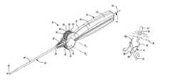
- FIG. 1is an isometric view of a suture passer illustrated according to various exemplary embodiments of the present disclosure
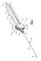
- FIG. 2is an exploded view of the suture passer of FIG. 1 ;
- FIG. 3is a longitudinal sectional view of a tube of the suture passer of FIG. 1 ;
- FIG. 4is a longitudinal sectional view of the suture passer of FIG. 1 ;
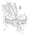
- FIG. 5is an isometric view of the suture passer of FIG. 1 , wherein a portion of a handle member has been removed;
- FIGS. 6-10are isometric views of the suture passer of FIG. 1 shown being used to pass a suture through anatomical tissue.
- a suture passer assembly 10is illustrated according to various exemplary embodiments of the present disclosure.
- the suture passer assembly 10can be used for manipulating a suture 12 ( FIGS. 6-10 ).
- a wire member 14FIGS. 7 and 8
- the suture passer assembly 10can be used to selectively move the wire member 14 for manipulating the suture 12 (e.g., for passing the suture 12 through anatomical tissue) as will be discussed in greater detail below.
- the suture passer assembly 10can include a handle member 16 .
- the handle member 16can include a first portion 18 and a second portion 20 that are joined together in a clam-shell or other type of configuration.
- the handle member 16can be made of a polymeric or other type of material.
- the first and second portions 18 , 20can cooperate to define a handle end 22 of the handle member 16 , which the user (e.g., a surgeon) can comfortably hold in one hand.
- the first and second portions 18 , 20can also cooperate to define a lead end 28 of the handle member 16 .
- the lead end 28can be frustoconical in shape and can be disposed on an opposite end of the handle member 16 from the handle end 22 .
- first and second portions 18 , 20can also define a first hub 24 and a second hub 26 ( FIG. 2 ).
- the hubs 24 , 26can be cylindrical and can extend perpendicularly between the first and second portions 18 , 20 , within the handle member 16 .
- the handle member 16can define a handle passage 30 ( FIG. 4 ) that extends longitudinally therethrough along an axis X. As shown in FIG. 4 , the wire member 14 can be moveably received within the handle passage 30 .
- the suture passer assembly 10can also include at least one grasping member 32 a , 32 b that are operable to selectively grasp and advance the wire member 14 relative to the handle member 16 and other portions of the assembly 10 .
- the grasping members 32 a , 32 bcould be embodied in ways other than the wheels 34 , 35 (e.g., such as levers, sliders, etc.) without departing from the scope of the present disclosure.
- the wheels 34 , 35can both be cylindrical and can both include an outer diameter surface 36 .
- the outer diameter surface 36can be defined by sets of teeth 38 (cogs, radial projections, etc.).
- the teeth 38can have a generally triangular profile as shown in FIG. 5 , but the teeth 38 can have any suitable grippable or engageable shape.
- the outer diameter surface 36can also be defined by a compressible member 40 of the respective wheel 34 , 35 .
- the compressible member 40can be made from a compressible, but relatively high friction material, such as rubber, foam, etc. However, the member 40 can be substantially incompressible and rigid in some embodiments as well. Also, in the embodiments shown in FIG. 5 , the compressible member 40 can be an annular band that is disposed longitudinally between the sets of teeth 38 of the respective wheel 34 , 35 .
- the wheels 34 , 35can be rotationally supported on the hubs 24 , 26 , respectively ( FIG. 4 ). As such, the wheels 34 , 35 can rotate about respective rotational axes R 1 , R 2 relative to the handle member 16 .
- the compressible member 40can abut and frictionally engage the wire member 14 .
- rotation of the wheels 34 , 35 about the axes R 1 , R 2can advance (i.e., push or pull) the wire member 14 within the assembly 10 .
- the wheels 34 , 35can be mounted such that the set of teeth 38 of the first wheel 34 can meshingly engage the set of teeth 38 of the second wheel 35 . Accordingly, the user can drivingly rotate only one wheel 34 , 35 to thereby drivingly rotate the other wheel 34 , 35 for added convenience and improved ergonomics.
- the outer diameter surface 36can include radial projections having shapes, spacing, etc. other than those of the illustrated teeth 38 for meshingly engaging the wheels 34 , 35 . Additionally, in some embodiments, the outer diameter surfaces 36 can be smooth such that the wheels 34 , 35 do not meshingly engage. Otherwise, in some embodiments, the outer diameter surfaces 36 can be smooth and can frictionally engage each other so that the wheels 34 , 35 can rotatably drive each other.
- the assembly 10can include a hollow tube 42 .
- the hollow tube 42can be a monolithic body (i.e., single body, uni-body construction, etc.).
- the tube 42can be constructed from metal or polymer.
- the tube 42can also extend along the longitudinal axis X.
- the tube 42can define a first end 44 , a second end 46 , and a tube wall 48 .
- the first end 44 and much of the second end 46can be axially straight; however, terminal portions of the second end 46 can axially curve as shown in FIGS. 1 and 2 .
- the second end 46can also include sharpened edges such that the second end 46 can be used for cutting anatomical tissue as will be discussed.
- the tube wall 48can define an inner tube surface 50 and an outer tube surface 52 as shown in FIG. 3 .
- a tube passage 53can extend longitudinally along the axis X through the tube 42 .
- the tube passage 53can extend continuously along the tube 42 between the first end 44 and the second end 46 .
- the wire member 14can be moveably received within the tube passage 53 .
- the tube 42can be fixedly attached and supported by the handle member 16 . More specifically, the first and second portions 18 , 20 of the handle member 16 can be attached such that the first end 44 of the tube 42 is enclosed within the handle passage 30 and sandwiched between the first and second portions 18 , 20 of the handle member 16 . As shown in FIGS. 2 and 4 , the tube wall 48 can include one or more orientation openings 59 (e.g., slots) that receive complementary projections of the first and/or second portions 18 , 20 for further securing the tube 42 to the handle member 16 . Adhesives, fasteners, or other means can additionally be used for securing the tube 42 to the handle member 16 . With the first end 44 secured to the handle member 16 , the second end 46 of the tube 42 can extend out from and can be exposed from the handle member 16 .
- orientation openings 59e.g., slots
- the tube wall 48can include at least one aperture 54 .
- the aperture 54can be disposed between the first and second ends 44 , 46 of the tube 42 .
- the tube wall 48includes two apertures 54 that are embodied as respective elongate slots 56 , 58 .
- the slots 56 , 58can extend radially through both the inner tube surface 50 and the outer tube surface 52 .
- the slots 56 , 58can extend substantially parallel to the axis X and can be disposed symmetrically on opposite sides of the axis X.
- the slots 56 , 58can taper outward from the inner tube surface 50 to the outer tube surface 52 .
- the tube 42can include any number of apertures 54
- the aperture(s) 54can have any suitable shape and any suitable position on the tube wall 48 .
- a first portion 60 of each wheel 34 , 35can be received within the slots 56 , 58 , respectively.
- the first portion 60is defined at an inner radial segment of the compressible member 40 as the wheels 34 , 35 rotate.
- These first portions 60extend through the tube wall 48 and radially into the tube passage 53 via the respective slot 56 , 58 .
- the slots 56 , 58can be shaped and sized such that the first portion 60 substantially fills the entire respective slot 56 , 58 .
- the remaining portionsi.e., second portions 62
- the second portion 62can be defined on the outer radial portions of the compressible members 40 .
- each of the sets of teeth 38can remain outside the tube 42 because the teeth 38 are spaced away on either side of the respective compressible members 40 (along the respective rotational axis R 1 , R 2 ).
- the handle member 16can include openings 63 ( FIGS. 1 and 4 ) that partially expose the respective second portions 62 of the wheels 34 , 35 so that the user can contact the wheels 34 , 35 .
- the wire member 14can be a continuous, flexible wire having a proximal end 64 and a distal end 66 .
- the wire member 14can be made from Nitinol, a polymer or other suitable material.
- the distal end 66can include a diamond-shaped loop 68 .
- the loop 68can be resiliently compressible.
- the distal end 66can include opposed pinchers, a hook, or other devices.
- the wire member 14can be moveably received within the handle passage 30 and the tube passage 53 . Specifically, to load the wire member 14 , the wire member 14 can be inserted into the handle passage 30 defined by the handle end 22 and advanced along the axis X toward the tube 42 .
- the wire member 14can advance easily into the first end 44 of the tube 42 and advance between the wheels 34 , 35 as shown in FIG. 4 . Then, the wheels 34 , 35 can be rotated to further advance the distal end 66 toward the second end 46 of the tube 42 .
- the distal end 66 of the wire member 14can be relatively easily and conveniently advanced toward the second end 46 of the tube 42 .
- the tube 42is monolithic (i.e., single body, uni-body, etc.), because the opening 59 is blocked by the handle member 16 , and because the slots 56 , 58 are blocked by the first portions 60 of the wheels 34 , 35 .
- the wire member 14has little or no ability to advance out of the tube 42 until the distal end 66 reaches the second end 46 of the tube 42 . Accordingly, the suture passer assembly 10 can be prepared for use relatively quickly and conveniently.
- the loop 68can be selectively advanced out and retracted into the second end 46 of the tube 42 . This can be accomplished by drivingly rotating the wheels 34 , 35 . As mentioned above, the user can apply force to only one wheel 34 , 35 and because the wheels 34 , 35 are meshingly engaged, both wheels 34 , 35 can advance the wire member 14 for added convenience.
- FIGS. 6-10illustrate exemplary uses of the suture passer assembly 10 .
- the suture passer assembly 10can be used to repair a damaged rotator cuff; however, it will be appreciated that the suture passer assembly 10 can be used for repairing any anatomical feature. Also, the assembly 10 can be used arthroscopically in some embodiments.
- the suture 12can include an anchor 71 that can be anchored (e.g., threaded) into a first anatomical feature 74 (e.g., bone tissue).
- the suture 12can also include two flexible ties 72 a , 72 b that extend from the anchor.
- one or more incisionscan be made in the patient's skin, and the anchor 71 can be fixed to the first anatomical feature 74 .
- the ties 72 a , 72 bcan be initially untied as shown in FIG. 6 .
- an openingsuch as a piercing or an incision 78 can be made in a second anatomical feature 76 (e.g., soft tissue such as a torn rotator cuff).
- the incision 78can be in communication with one or more other incisions formed within the patient's skin.
- the incision 78can be made directly by the sharpened edges of the second end 46 of the tube 42 .
- the incision 78can be made using another cutting tool.
- a cannula(not shown) can be inserted into the incision 78 and the second end 46 of the tube 42 can be advanced through the incision 78 via the cannula.
- the wheels 34 , 35can be rotated in a first direction to advance the loop 68 out of the second end 46 ( FIG. 7 ).
- the loop 68can bias open to a width that is larger than that of the second end 46 .
- a tool 73can be inserted into the patient (e.g., through an incision that is not shown), and the tool 73 can be used to grab one of the ties 72 a and advance the tie 72 a into the loop 68 as indicated by the arrow in FIG. 8 .
- the wheels 34 , 35 of the suture passer assembly 10can be rotated in a second direction to retract the loop 68 back into the second end 46 .
- the loop 68can resiliently flex to close around the tie 72 a .
- the tie 72 acan be restrained and captured within the loop 68 and/or restrained between the loop 68 and the inner tube surface 50 of the tube 42 as shown in FIG. 9 .
- the surgeoncan pull the assembly 10 back through the incision 78 , thereby pulling the tie 72 through the incision. Subsequently, the ties 72 a , 72 b can be tied in one or more conventional knots to thereby attach the first and second anatomical features 74 , 76 together.
- the suture passer assembly 10can allow the user to conveniently load the wire member 14 therein. Also, the suture passer assembly 10 can allow the user to comfortably and accurately control advancement of the wire member 14 within the tube 42 . As a result, the user can more quickly and efficiently perform surgical procedures using sutures 12 .
Landscapes
- Health & Medical Sciences (AREA)
- Life Sciences & Earth Sciences (AREA)
- Surgery (AREA)
- Heart & Thoracic Surgery (AREA)
- Engineering & Computer Science (AREA)
- Biomedical Technology (AREA)
- Nuclear Medicine, Radiotherapy & Molecular Imaging (AREA)
- Medical Informatics (AREA)
- Molecular Biology (AREA)
- Animal Behavior & Ethology (AREA)
- General Health & Medical Sciences (AREA)
- Public Health (AREA)
- Veterinary Medicine (AREA)
- Surgical Instruments (AREA)
Abstract
Description
Claims (22)
Priority Applications (2)
| Application Number | Priority Date | Filing Date | Title |
|---|---|---|---|
| US13/652,003US9089321B2 (en) | 2012-10-15 | 2012-10-15 | Wheeled suture passer |
| US14/794,373US9877716B2 (en) | 2012-10-15 | 2015-07-08 | Wheeled suture passer |
Applications Claiming Priority (1)
| Application Number | Priority Date | Filing Date | Title |
|---|---|---|---|
| US13/652,003US9089321B2 (en) | 2012-10-15 | 2012-10-15 | Wheeled suture passer |
Related Child Applications (1)
| Application Number | Title | Priority Date | Filing Date |
|---|---|---|---|
| US14/794,373ContinuationUS9877716B2 (en) | 2012-10-15 | 2015-07-08 | Wheeled suture passer |
Publications (2)
| Publication Number | Publication Date |
|---|---|
| US20140107673A1 US20140107673A1 (en) | 2014-04-17 |
| US9089321B2true US9089321B2 (en) | 2015-07-28 |
Family
ID=50476045
Family Applications (2)
| Application Number | Title | Priority Date | Filing Date |
|---|---|---|---|
| US13/652,003Active2033-06-29US9089321B2 (en) | 2012-10-15 | 2012-10-15 | Wheeled suture passer |
| US14/794,373Active2033-04-06US9877716B2 (en) | 2012-10-15 | 2015-07-08 | Wheeled suture passer |
Family Applications After (1)
| Application Number | Title | Priority Date | Filing Date |
|---|---|---|---|
| US14/794,373Active2033-04-06US9877716B2 (en) | 2012-10-15 | 2015-07-08 | Wheeled suture passer |
Country Status (1)
| Country | Link |
|---|---|
| US (2) | US9089321B2 (en) |
Cited By (3)
| Publication number | Priority date | Publication date | Assignee | Title |
|---|---|---|---|---|
| US20160000426A1 (en)* | 2012-10-15 | 2016-01-07 | Biomet Sports Medicine, Llc | Wheeled Suture Passer |
| US11109877B2 (en) | 2016-12-21 | 2021-09-07 | Olympus Corporation | Treatment instrument that includes an operation dial |
| US12053172B2 (en) | 2017-12-14 | 2024-08-06 | Conmed Corporation | Suture passer device |
Families Citing this family (9)
| Publication number | Priority date | Publication date | Assignee | Title |
|---|---|---|---|---|
| US9629633B2 (en)* | 2013-07-09 | 2017-04-25 | Covidien Lp | Surgical device, surgical adapters for use between surgical handle assembly and surgical loading units, and methods of use |
| US10441449B1 (en) | 2018-05-30 | 2019-10-15 | Vesper Medical, Inc. | Rotary handle stent delivery system and method |
| US10449073B1 (en) | 2018-09-18 | 2019-10-22 | Vesper Medical, Inc. | Rotary handle stent delivery system and method |
| US10667805B1 (en) | 2019-05-17 | 2020-06-02 | Composite Surgical, LLC | Steerable suture retriever |
| US11154295B1 (en) | 2020-05-14 | 2021-10-26 | Composite Surgical, LLC | Steerable suture retriever |
| US10973512B1 (en) | 2020-05-14 | 2021-04-13 | Composite Surgical, LLC | Steerable suture retriever |
| US11219541B2 (en) | 2020-05-21 | 2022-01-11 | Vesper Medical, Inc. | Wheel lock for thumbwheel actuated device |
| KR102193692B1 (en)* | 2020-08-04 | 2020-12-21 | 황학순 | Surgical tool set for performing Subscapular muscle-Loop closure-Fixed surgery |
| KR102632301B1 (en)* | 2021-11-23 | 2024-02-01 | 채창영 | Surgical tools for sutures of bone and muscles |
Citations (24)
| Publication number | Priority date | Publication date | Assignee | Title |
|---|---|---|---|---|
| US2959172A (en) | 1957-08-27 | 1960-11-08 | American Cystoscope Makers Inc | Self-threading suturing instrument |
| US4890615A (en) | 1987-11-05 | 1990-01-02 | Concept, Inc. | Arthroscopic suturing instrument |
| US5281237A (en) | 1992-09-25 | 1994-01-25 | Gimpelson Richard J | Surgical stitching device and method of use |
| US5439467A (en) | 1991-12-03 | 1995-08-08 | Vesica Medical, Inc. | Suture passer |
| US5562683A (en) | 1993-07-12 | 1996-10-08 | Mitek Surgical Products, Inc. | Surgical repair kit and its method of use |
| US5676675A (en) | 1992-09-10 | 1997-10-14 | Grice; O. Drew | Laparo-suture needle and method for use thereof |
| US5810848A (en) | 1996-08-21 | 1998-09-22 | Hayhurst; John O. | Suturing system |
| US5830231A (en) | 1997-03-19 | 1998-11-03 | Geiges, Jr.; John J. | Handle and actuating mechanism for surgical instruments |
| US5993466A (en) | 1997-06-17 | 1999-11-30 | Yoon; Inbae | Suturing instrument with multiple rotatably mounted spreadable needle holders |
| US6206893B1 (en) | 1993-11-08 | 2001-03-27 | Perclose, Inc. | Device and method for suturing of internal puncture sites |
| US6629984B1 (en) | 1998-07-07 | 2003-10-07 | Kwan-Ho Chan | Surgical repair kit and its method of use |
| US20050080476A1 (en)* | 2003-10-09 | 2005-04-14 | Gunderson Richard C. | Medical device delivery system |
| US7004951B2 (en) | 2001-10-04 | 2006-02-28 | Gibbens Group Llc | Cycling suturing and knot-tying device |
| US20090018553A1 (en) | 2007-07-09 | 2009-01-15 | Neotract, Inc. | Multi-actuating trigger anchor delivery system |
| US20110202074A1 (en) | 2008-04-09 | 2011-08-18 | Talmo Paul A | Devices and methods for deploying medical sutures |
| US20120059396A1 (en) | 2009-10-29 | 2012-03-08 | Harris Jason L | Device For Deploying A Fastener For Use In A Gastric Volume Reduction Procedure |
| US20120123448A1 (en) | 2010-09-10 | 2012-05-17 | James Flom | Method and apparatus for passing suture through tissue |
| US8303604B2 (en) | 2004-11-05 | 2012-11-06 | Biomet Sports Medicine, Llc | Soft tissue repair device and method |
| US20130116710A1 (en) | 2011-11-07 | 2013-05-09 | C.R. Bard, Inc. | Instruments for delivering transfascial sutures and methods of transfascial suturing |
| US8490713B2 (en) | 2009-10-06 | 2013-07-23 | Covidien Lp | Handle assembly for endoscopic suturing device |
| US8636752B2 (en) | 2006-10-05 | 2014-01-28 | Covidien Lp | Flexible endoscopic stitching devices |
| US8679135B2 (en) | 2010-05-25 | 2014-03-25 | Biomet Sports Medicine, Llc | Method and apparatus for passing a suture |
| US8696688B2 (en) | 2006-02-02 | 2014-04-15 | Biomet Sports Medicine, Llc | Method and apparatus for passing a flexible strand |
| US8709022B2 (en) | 2011-05-24 | 2014-04-29 | Biomet Sports Medicine, Llc | Method and apparatus for passing a suture |
Family Cites Families (2)
| Publication number | Priority date | Publication date | Assignee | Title |
|---|---|---|---|---|
| US20040006380A1 (en)* | 2002-07-05 | 2004-01-08 | Buck Jerrick C. | Stent delivery system |
| US9089321B2 (en) | 2012-10-15 | 2015-07-28 | Biomet Sports Medicine, Llc | Wheeled suture passer |
- 2012
- 2012-10-15USUS13/652,003patent/US9089321B2/enactiveActive
- 2015
- 2015-07-08USUS14/794,373patent/US9877716B2/enactiveActive
Patent Citations (31)
| Publication number | Priority date | Publication date | Assignee | Title |
|---|---|---|---|---|
| US2959172A (en) | 1957-08-27 | 1960-11-08 | American Cystoscope Makers Inc | Self-threading suturing instrument |
| US4890615A (en) | 1987-11-05 | 1990-01-02 | Concept, Inc. | Arthroscopic suturing instrument |
| US4923461A (en) | 1987-11-05 | 1990-05-08 | Concept, Inc. | Method of arthroscopic suturing of tissue |
| US4890615B1 (en) | 1987-11-05 | 1993-11-16 | Linvatec Corporation | Arthroscopic suturing instrument |
| US4923461B1 (en) | 1987-11-05 | 1994-10-18 | Linvatec Corp | Method of arthroscopic suturing of tissue |
| US4923461B2 (en) | 1987-11-05 | 1995-06-20 | Linvatec Corp | Method of arthroscopic suturing |
| US5439467A (en) | 1991-12-03 | 1995-08-08 | Vesica Medical, Inc. | Suture passer |
| US5676675A (en) | 1992-09-10 | 1997-10-14 | Grice; O. Drew | Laparo-suture needle and method for use thereof |
| US5281237A (en) | 1992-09-25 | 1994-01-25 | Gimpelson Richard J | Surgical stitching device and method of use |
| US5562683A (en) | 1993-07-12 | 1996-10-08 | Mitek Surgical Products, Inc. | Surgical repair kit and its method of use |
| US5562687A (en) | 1993-07-12 | 1996-10-08 | Mitek Surgical Products, Inc. | Surgical repair kit and its method of use |
| US5776151A (en) | 1993-07-12 | 1998-07-07 | Chan; Kwan-Ho | Surgical repair kit and its method of use |
| US20120143224A1 (en) | 1993-07-12 | 2012-06-07 | Kwan-Ho Chan | Surgical repair kit and its method of use |
| US6206893B1 (en) | 1993-11-08 | 2001-03-27 | Perclose, Inc. | Device and method for suturing of internal puncture sites |
| US5810848A (en) | 1996-08-21 | 1998-09-22 | Hayhurst; John O. | Suturing system |
| US5830231A (en) | 1997-03-19 | 1998-11-03 | Geiges, Jr.; John J. | Handle and actuating mechanism for surgical instruments |
| US5993466A (en) | 1997-06-17 | 1999-11-30 | Yoon; Inbae | Suturing instrument with multiple rotatably mounted spreadable needle holders |
| US6629984B1 (en) | 1998-07-07 | 2003-10-07 | Kwan-Ho Chan | Surgical repair kit and its method of use |
| US7004951B2 (en) | 2001-10-04 | 2006-02-28 | Gibbens Group Llc | Cycling suturing and knot-tying device |
| US20050080476A1 (en)* | 2003-10-09 | 2005-04-14 | Gunderson Richard C. | Medical device delivery system |
| US8303604B2 (en) | 2004-11-05 | 2012-11-06 | Biomet Sports Medicine, Llc | Soft tissue repair device and method |
| US8696688B2 (en) | 2006-02-02 | 2014-04-15 | Biomet Sports Medicine, Llc | Method and apparatus for passing a flexible strand |
| US8636752B2 (en) | 2006-10-05 | 2014-01-28 | Covidien Lp | Flexible endoscopic stitching devices |
| US20090018553A1 (en) | 2007-07-09 | 2009-01-15 | Neotract, Inc. | Multi-actuating trigger anchor delivery system |
| US20110202074A1 (en) | 2008-04-09 | 2011-08-18 | Talmo Paul A | Devices and methods for deploying medical sutures |
| US8490713B2 (en) | 2009-10-06 | 2013-07-23 | Covidien Lp | Handle assembly for endoscopic suturing device |
| US20120059396A1 (en) | 2009-10-29 | 2012-03-08 | Harris Jason L | Device For Deploying A Fastener For Use In A Gastric Volume Reduction Procedure |
| US8679135B2 (en) | 2010-05-25 | 2014-03-25 | Biomet Sports Medicine, Llc | Method and apparatus for passing a suture |
| US20120123448A1 (en) | 2010-09-10 | 2012-05-17 | James Flom | Method and apparatus for passing suture through tissue |
| US8709022B2 (en) | 2011-05-24 | 2014-04-29 | Biomet Sports Medicine, Llc | Method and apparatus for passing a suture |
| US20130116710A1 (en) | 2011-11-07 | 2013-05-09 | C.R. Bard, Inc. | Instruments for delivering transfascial sutures and methods of transfascial suturing |
Non-Patent Citations (6)
| Title |
|---|
| EZPass Suture Passers. Biomet Sports Medicine. (2014) 2 pages. |
| Shoulder Arthroscopy. Bioraptor? Curved Osteoraptor? Curved Suture Anchors and Guide System. Smith & Nephew. (2011). pp. 1-53. |
| SpeedPass(TM) Suture Retrievers. Arthrotek® a Biomet Company brochure. (2004). 2 pages. |
| SpeedPass™ Suture Retrievers. Arthrotek® a Biomet Company brochure. (2004). 2 pages. |
| The Material Difference. Biomet® Sports Medicine. (2008). pp. 1-12. |
| The Next Generation in Shoulder & Elbow Repair and Reconstruction Technology. Arthrex® brochure. (2014) pp. 1-55. |
Cited By (4)
| Publication number | Priority date | Publication date | Assignee | Title |
|---|---|---|---|---|
| US20160000426A1 (en)* | 2012-10-15 | 2016-01-07 | Biomet Sports Medicine, Llc | Wheeled Suture Passer |
| US9877716B2 (en)* | 2012-10-15 | 2018-01-30 | Biomet Sports Medicine, Llc | Wheeled suture passer |
| US11109877B2 (en) | 2016-12-21 | 2021-09-07 | Olympus Corporation | Treatment instrument that includes an operation dial |
| US12053172B2 (en) | 2017-12-14 | 2024-08-06 | Conmed Corporation | Suture passer device |
Also Published As
| Publication number | Publication date |
|---|---|
| US20160000426A1 (en) | 2016-01-07 |
| US9877716B2 (en) | 2018-01-30 |
| US20140107673A1 (en) | 2014-04-17 |
Similar Documents
| Publication | Publication Date | Title |
|---|---|---|
| US9877716B2 (en) | Wheeled suture passer | |
| US11712232B2 (en) | Surgical fastening | |
| JP6121155B2 (en) | Nodule instability anchor | |
| US5810845A (en) | Ligating instrument with multiple loop ligature supply and methods therefor | |
| CN103892879B (en) | Multi-piece anchor inserter | |
| EP3025654B1 (en) | Medical implement for manipulating sutures particularly useful in arthroscopic surgery | |
| US11672526B2 (en) | Methods and devices for passing sutures around anatomical structures | |
| EP2403416B1 (en) | Side loaded medical implement particularly useful in arthroscopic surgery | |
| US20030004580A1 (en) | Strip-like implant | |
| JP6250308B2 (en) | Surgical fasteners and apparatus for placing surgical fasteners | |
| CA2874006A1 (en) | Knotless collapsible sutures and methods for suturing | |
| JP2016083361A (en) | Biceps tenodesis implants and delivery tools | |
| US9173654B2 (en) | System for tissue repair | |
| JP7337487B2 (en) | Knotless suture fixation using two awl shafts | |
| US20110270281A1 (en) | Articulating Axial Needle Grasper |
Legal Events
| Date | Code | Title | Description |
|---|---|---|---|
| AS | Assignment | Owner name:BIOMET SPORTS MEDICINE, LLC, INDIANA Free format text:ASSIGNMENT OF ASSIGNORS INTEREST;ASSIGNORS:SNYDER, TERRY H.;FRITZINGER, DANIEL D.;SIGNING DATES FROM 20121003 TO 20121010;REEL/FRAME:029223/0642 | |
| STCF | Information on status: patent grant | Free format text:PATENTED CASE | |
| AS | Assignment | Owner name:BIOMET, INC., INDIANA Free format text:ASSIGNMENT OF ASSIGNORS INTEREST;ASSIGNOR:BIOMET U.S. RECONSTRUCTION, LLC;REEL/FRAME:045935/0557 Effective date:20171103 Owner name:BIOMET U.S. RECONSTRUCTION, LLC, INDIANA Free format text:ASSIGNMENT OF ASSIGNORS INTEREST;ASSIGNOR:BIOMET SPORTS MEDICINE, LLC;REEL/FRAME:045935/0497 Effective date:20171103 Owner name:BIOMET MANUFACTURING, LLC, INDIANA Free format text:ASSIGNMENT OF ASSIGNORS INTEREST;ASSIGNOR:ZB MANUFACTURING, LLC;REEL/FRAME:045935/0673 Effective date:20171103 Owner name:ZB MANUFACTURING, LLC, INDIANA Free format text:ASSIGNMENT OF ASSIGNORS INTEREST;ASSIGNOR:BIOMET, INC.;REEL/FRAME:045935/0570 Effective date:20171103 | |
| MAFP | Maintenance fee payment | Free format text:PAYMENT OF MAINTENANCE FEE, 4TH YEAR, LARGE ENTITY (ORIGINAL EVENT CODE: M1551); ENTITY STATUS OF PATENT OWNER: LARGE ENTITY Year of fee payment:4 | |
| MAFP | Maintenance fee payment | Free format text:PAYMENT OF MAINTENANCE FEE, 8TH YEAR, LARGE ENTITY (ORIGINAL EVENT CODE: M1552); ENTITY STATUS OF PATENT OWNER: LARGE ENTITY Year of fee payment:8 |