US9088216B2 - Controller for a synchronous rectifier switch - Google Patents
Controller for a synchronous rectifier switchDownload PDFInfo
- Publication number
- US9088216B2 US9088216B2US12/689,881US68988110AUS9088216B2US 9088216 B2US9088216 B2US 9088216B2US 68988110 AUS68988110 AUS 68988110AUS 9088216 B2US9088216 B2US 9088216B2
- Authority
- US
- United States
- Prior art keywords
- switch
- synchronous rectifier
- coupled
- terminal
- gate
- Prior art date
- Legal status (The legal status is an assumption and is not a legal conclusion. Google has not performed a legal analysis and makes no representation as to the accuracy of the status listed.)
- Active, expires
Links
Images


Classifications
- H—ELECTRICITY
- H02—GENERATION; CONVERSION OR DISTRIBUTION OF ELECTRIC POWER
- H02M—APPARATUS FOR CONVERSION BETWEEN AC AND AC, BETWEEN AC AND DC, OR BETWEEN DC AND DC, AND FOR USE WITH MAINS OR SIMILAR POWER SUPPLY SYSTEMS; CONVERSION OF DC OR AC INPUT POWER INTO SURGE OUTPUT POWER; CONTROL OR REGULATION THEREOF
- H02M7/00—Conversion of AC power input into DC power output; Conversion of DC power input into AC power output
- H02M7/02—Conversion of AC power input into DC power output without possibility of reversal
- H02M7/04—Conversion of AC power input into DC power output without possibility of reversal by static converters
- H02M7/12—Conversion of AC power input into DC power output without possibility of reversal by static converters using discharge tubes with control electrode or semiconductor devices with control electrode
- H02M7/21—Conversion of AC power input into DC power output without possibility of reversal by static converters using discharge tubes with control electrode or semiconductor devices with control electrode using devices of a triode or transistor type requiring continuous application of a control signal
- H02M7/217—Conversion of AC power input into DC power output without possibility of reversal by static converters using discharge tubes with control electrode or semiconductor devices with control electrode using devices of a triode or transistor type requiring continuous application of a control signal using semiconductor devices only
- H02M7/219—Conversion of AC power input into DC power output without possibility of reversal by static converters using discharge tubes with control electrode or semiconductor devices with control electrode using devices of a triode or transistor type requiring continuous application of a control signal using semiconductor devices only in a bridge configuration
- H—ELECTRICITY
- H02—GENERATION; CONVERSION OR DISTRIBUTION OF ELECTRIC POWER
- H02M—APPARATUS FOR CONVERSION BETWEEN AC AND AC, BETWEEN AC AND DC, OR BETWEEN DC AND DC, AND FOR USE WITH MAINS OR SIMILAR POWER SUPPLY SYSTEMS; CONVERSION OF DC OR AC INPUT POWER INTO SURGE OUTPUT POWER; CONTROL OR REGULATION THEREOF
- H02M1/00—Details of apparatus for conversion
- H02M1/0083—Converters characterised by their input or output configuration
- H02M1/0085—Partially controlled bridges
- H—ELECTRICITY
- H02—GENERATION; CONVERSION OR DISTRIBUTION OF ELECTRIC POWER
- H02M—APPARATUS FOR CONVERSION BETWEEN AC AND AC, BETWEEN AC AND DC, OR BETWEEN DC AND DC, AND FOR USE WITH MAINS OR SIMILAR POWER SUPPLY SYSTEMS; CONVERSION OF DC OR AC INPUT POWER INTO SURGE OUTPUT POWER; CONTROL OR REGULATION THEREOF
- H02M1/00—Details of apparatus for conversion
- H02M1/42—Circuits or arrangements for compensating for or adjusting power factor in converters or inverters
- H02M1/4208—Arrangements for improving power factor of AC input
- H02M1/4225—Arrangements for improving power factor of AC input using a non-isolated boost converter
- Y—GENERAL TAGGING OF NEW TECHNOLOGICAL DEVELOPMENTS; GENERAL TAGGING OF CROSS-SECTIONAL TECHNOLOGIES SPANNING OVER SEVERAL SECTIONS OF THE IPC; TECHNICAL SUBJECTS COVERED BY FORMER USPC CROSS-REFERENCE ART COLLECTIONS [XRACs] AND DIGESTS
- Y02—TECHNOLOGIES OR APPLICATIONS FOR MITIGATION OR ADAPTATION AGAINST CLIMATE CHANGE
- Y02B—CLIMATE CHANGE MITIGATION TECHNOLOGIES RELATED TO BUILDINGS, e.g. HOUSING, HOUSE APPLIANCES OR RELATED END-USER APPLICATIONS
- Y02B70/00—Technologies for an efficient end-user side electric power management and consumption
- Y02B70/10—Technologies improving the efficiency by using switched-mode power supplies [SMPS], i.e. efficient power electronics conversion e.g. power factor correction or reduction of losses in power supplies or efficient standby modes
- Y02B70/126—
- Y02B70/1408—
Definitions
- the present inventionis directed, in general, to power electronics and, more specifically, to controller for a power converter and method of operating the same.
- a switched-mode power converter(also referred to as a “power converter” or “regulator”) is a power supply or power processing circuit that converts an input voltage waveform into a specified output voltage waveform.
- AC-DC power convertersconvert an alternating current (“ac”) input voltage into a direct current (“dc”) output voltage.
- Controllers associated with the power convertersmanage an operation thereof by controlling the conduction periods of power switches employed therein.
- the controllersare coupled between an input and output of the power converter in a feedback loop configuration (also referred to as a “control loop” or “closed control loop”).
- power convertersTo produce a dc output voltage, power converters often employ diodes to rectify an ac voltage.
- the rectifying devicescan introduce a power loss component in a power converter due to the forward voltage drop across the diode, particularly in a power converter that produces an output voltage of five volts or less.
- Schottky diodeswhich have a relatively low forward voltage drop, are often employed in low-voltage power converter applications to reduce a diode forward voltage drop.
- passive rectifying devicessuch as Schottky diodes typically cannot achieve forward voltage drops of less than about 0.35 volts (“V”), and typically cannot sustain a reverse voltage greater than about 60 volts, thereby limiting a conversion efficiency of the power converter.
- V0.35 volts
- power convertersoften employ rectifying devices that may have forward voltage drops less than about 0.1 volts.
- an active switch or active semiconductor switchsuch as a metal-oxide semiconductor field-effect transistor (“MOSFET”), which provides a resistive voltage drop, is often employed to replace a diode.
- MOSFETmetal-oxide semiconductor field-effect transistor
- An active semiconductor switchmust be periodically driven into conduction and non-conduction modes or states in synchronism with a periodic waveform of an ac voltage (e.g., an ac voltage produced across an input to the power converter). The active semiconductor switches may thereby avoid the higher forward voltage drops inherent in the passive rectifying devices.
- a design issue introduced by substituting an active semiconductor switch for a diodeis the need to provide a drive signal therefor that is accurately synchronized with the operation of the power converter to control the conduction and non-conduction modes or states of the active semiconductor switches, and that avoids conduction overlap with other semiconductor switches including diodes.
- An active semiconductor switch substituted for a diode in a power converteris generally referred to as a “synchronous rectifier” or “synchronous rectifier switch.”
- a conventional ac-to-dc power converteremploys a bridge rectifier to transform an ac sinusoidal input voltage waveform, such as an input voltage waveform produced by an ac mains, into a rectified sinusoidal waveform.
- a power factor correction (“PFC”) circuitconverts the rectified sinusoidal waveform into a dc waveform with a dc voltage level higher than the peak voltage of the sinusoidal input voltage.
- the bridge rectifieris usually constructed with four diodes. Due to the forward voltage drop of the diodes, significant power losses are produced by the diodes.
- a bridgeless boost PFC circuitmay be employed to address the power loss problem associated with the forward voltage drop of the diodes. As a result, conduction losses of the diodes are reduced.
- a bridgeless boost PFC circuithas several significant remaining problems that limit its application in low-cost, high-volume circuits.
- a two-inductor structure introduced by the circuitcauses the output voltage to float with respect to the input line voltage. As a result, the circuit produces a high level of electromagnetic interference (“EMI”) noise.
- EMIelectromagnetic interference
- boost inductoron the ac side makes it difficult to sense the ac line voltage and the inductor current and the control is a more complicated process compared with control schemes used for a simpler boost PFC circuit or boost power converter coupled to a bridge rectifier. As a result, the bridgeless boost PFC circuit has found limited application.
- the controllerincludes an amplifier configured to enable a turn-on delay for the first synchronous rectifier switch.
- the controlleralso includes a discharge switch having first and second switched terminals coupled to gate and source terminals, respectively, of the first synchronous rectifier switch and configured to discharge a gate-to-source capacitance of the first synchronous rectifier switch to enable a turn off thereof.
- FIG. 1illustrates a schematic diagram of an embodiment of a power converter including a bridge rectifier coupled to a boost power converter that provides an environment for application of the principles of the present invention
- FIG. 2illustrates a schematic diagram of an embodiment of a power converter including two synchronous rectifier switches in a bridge rectifier constructed according to the principles of the present invention
- FIG. 3illustrates a graphical representation of waveforms produced with overlapping gate drive signals for first and second synchronous rectifier switches
- FIG. 4illustrates a graphical representation of waveforms produced with gate drive signals for first and second synchronous rectifier switches
- FIG. 5illustrates a schematic diagram of an embodiment of a controller for a switch constructed according to the principles of the present invention
- FIG. 6illustrates a schematic diagram of an embodiment of a power converter including a bridge rectifier formed with first and second synchronous rectifier switches constructed in accordance with the principles of the present invention
- FIG. 7illustrates a graphical representation of waveforms produced with non-overlapping gate drive signals for first and second synchronous rectifier switches in accordance with the principles of the present invention
- FIG. 8illustrates a graphical representation demonstrating dead time between the first and second synchronous rectifier switches introduced with respect to FIG. 6 ;
- FIG. 9illustrates a schematic diagram of an embodiment of a controller for first and second synchronous rectifier switches constructed according to the principles of the present invention.
- FIGUREsare drawn to illustrate the relevant aspects of exemplary embodiments.
- the present inventionwill be described with respect to exemplary embodiments in a specific context, namely, a controller for a switch such as a synchronous rectifier switch with a delay turn on thereof, and a method of operating the same. While the principles of the present invention will be described in the environment of a power converter, any application that may benefit from a controller such as a power amplifier or a motor controller is well within the broad scope of the present invention. Additionally, while the principles of the present invention will be described with respect to field-effect transistors including gate, source and drain terminals, the principles are equally applicable to any types of switches having control and switched terminals.
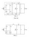
- FIG. 1illustrated is a schematic diagram of an embodiment of a power converter (e.g., an ac-to-dc power converter) including a bridge rectifier 110 coupled to a boost power converter 120 (also referred to as a “boost power train”) that provides an environment for application of the principles of the present invention.
- the bridge rectifier 110includes a plurality of bridge diodes D 1 , D 2 , D 3 , D 4 configured as a four-diode bridge rectifier coupled to an ac input voltage source (designated “V 1 ”) to produce a rectified waveform that is operative as an input voltage for the boost power converter 120 .
- the boost power converter 120includes boost inductor L 1 and boost power switch Q 1 .
- the boost power switch Q 1illustrated in FIG. 1 as an n-channel MOSFET, is controlled to conduct intermittently with a duty cycle D to produce a current in the boost inductor L 1 that is intermittently conducted to a boost diode D 5 with a complementary duty cycle 1 -D.
- the boost diode D 5rectifies the inductor current to produce a dc voltage across an output filter capacitor C 1 .
- the resistor R LOADrepresents a load connected to the output of the ac-to-dc power converter.
- a significant source of power loss in the power converter illustrated in FIG. 1is the forward voltage drop of the bridge diodes D 1 , D 2 , D 3 , D 4 .
- the bridge diodes D 1 , D 2 , D 3 , D 4may be replaced with active switches or active semiconductor switches functioning as synchronous rectifiers or synchronous rectifier switches with a substantially smaller forward voltage drop than passive diodes.
- An issue in the design of synchronous rectifiers formed with active switchesis cross conduction between a pair of synchronous rectifiers, thereby presenting a further power loss problem.
- FIG. 2illustrated is a schematic diagram of an embodiment of a power converter (e.g., an ac-dc power converter) including first and second synchronous rectifier switches SR 1 , SR 2 in a bridge rectifier constructed according to the principles of the present invention.
- a conventional synchronous rectifier arrangementcannot be employed to replace the diodes in the bridge rectifier because a conventional synchronous rectifier arrangement (see, e.g., U.S. Pat. No. 6,469,564 to Jansen) uses a diode and a transistor base-emitter p-n junction as two voltage-sensing inputs to determine when the active switch employed as the synchronous rectifier is enabled to conduct.
- a conventional synchronous rectifier arrangementis principally used when a single diode is employed, but suffers degradation of power converter efficiency when coupled to another active switch.
- a conventional synchronous rectifier arrangementis used to replace two or more diodes in a bridge rectifier (top two diodes, bottom two diodes, or upper and lower branch diodes as illustrated in FIG. 1 )
- cross conduction between the two diodesoccurs during a brief period of time when both diodes are enabled to conduct.
- a mismatch of the diode and base emitter p-n junction of the synchronous rectifier switch and the reverse recovery charge of the dioderesult in overlapping control terminal signals (e.g., gate drive signals), or at least not separated gate drive signals, for the two active switches (e.g., MOSFETs) employed as the synchronous rectifier switches.
- overlapping control terminal signalse.g., gate drive signals
- MOSFETstwo active switches
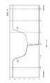
- FIG. 3illustrated is a graphical representation of waveforms produced with overlapping gate drive signals for first and second synchronous rectifier switches SR 1 , SR 2 .
- the first and second synchronous rectifier switches SR 1 , SR 2are coupled in a series arrangement wherein a shoot-through current is produced when both synchronous rectifier switches SR 1 , SR 2 are simultaneously enabled to conduct.
- input current spikes 310are illustrated every 10 milliseconds (“ms”) for a 50 hertz (“Hz”) input ac voltage due to diode cross conduction.
- msmilliseconds
- Hzhertz
- gate drive waveformsare illustrated that enable conduction of the first and second synchronous rectifier switches SR 1 , SR 2 without a period of separation between their high gate drive voltage levels (also referred to as gate drive signal overlap 320 ).
- the input voltage sourceis briefly coupled to a short circuit every half line cycle that produces a spike in current from the input voltage source.
- Such circuit operationgenerally results in a high level of electromagnetic interference (“EMI”), and increases conduction losses for the bridge rectifier.
- EMIelectromagnetic interference
- FIG. 4illustrated is a graphical representation of waveforms produced with gate drive signals for first and second synchronous rectifier switches SR 1 , SR 2 .
- a period of overlapis shown for conventional synchronous rectifier designs during which both synchronous rectifier switches SR 1 , SR 2 are enabled to conduct (first synchronous rectifier gate drive signal 410 and second synchronous rectifier gate drive signal 420 provide an overlap 430 ), producing thereby a spike in input current from the input voltage source.
- first synchronous rectifier gate drive signal 410 and second synchronous rectifier gate drive signal 420provide an overlap 430
- cross conduction therebetweenmay be substantially reduced.
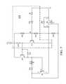
- FIG. 5illustrated is a schematic diagram of an embodiment of a controller for a switch (e.g., a synchronous rectifier switch SR) constructed according to the principles of the present invention.
- the controller illustrated in FIG. 5includes elements that charge or discharge a gate-to-source capacitance of the synchronous rectifier switch SR.
- Charging and discharging gate-to-source capacitanceis generally an obstacle for quickly enabling or disabling conductivity of an active switch such as a MOSFET employed as the synchronous rectifier switch SR.
- Quickly disabling conductivity of the synchronous rectifier switch SRis important for eliminating (or substantially eliminating) cross conduction thereof with another active switch in a power converter.
- a controller for the synchronous rectifier switch SRincludes an amplifier 510 with a threshold voltage produced in accordance with a plurality of series-coupled diodes D 6 , D 15 .
- the controllerfurther includes a discharge switch Q 3 (e.g., a pnp transistor) with switched terminals coupled between the source and gate terminals of the synchronous rectifier switch SR and a control terminal coupled to an output of the amplifier 510 .
- the discharge switch Q 3is formed with emitter (designated “e”), base (designated “b”), and collector (designated “c”) terminals.
- the synchronous rectifier switch SRis formed with source (designated “s”), gate (designated “g”), and drain (designated “d”) terminals.
- the emitter of the discharge switch Q 3is connected to the gate of the synchronous rectifier switch SR, and the collector of discharge switch Q 3 is connected to the source of synchronous rectifier switch SR.
- an amplifier switche.g., a npn transistor
- Q 12turns on due to current flowing into its base from a bias voltage source V CC through a resistor R 16 .
- a charge switche.g., transistor
- Q 11is turned off and the discharge switch Q 3 is turned on.
- a discharge switch Q 3which has its emitter and collector terminals connected to the gate and source terminals, respectively, of the synchronous rectifier switch SR, causes the gate charge of the synchronous rectifier switch SR to be quickly discharged, enabling thereby fast turn off of the synchronous rectifier switch SR.
- a discharge switch Q 3 coupled to terminals of a synchronous rectifier switch SRis configured to enable the quick discharge of a gate-to-source capacitance thereof in response to a back biased condition of the body diode D 30 of the synchronous rectifier switch SR.
- the amplifier switch Q 12When the body diode D 30 of synchronous rectifier power switch SR is forward biased, and voltage of the node K becomes sufficiently lower than voltage of the node A, the amplifier switch Q 12 turns off.
- the diodes D 6 , D 15provide a threshold for the voltage of the node K being lower than the voltage of the node A to turn off the amplifier switch Q 12 , thereby introducing a turn-on delay for the synchronous rectifier switch SR.
- Turning off the amplifier switch Q 12enables a resistor R 14 to provide a bias current from the bias voltage source V CC to the base of the charge switch Q 11 that is thereby turned on.
- a charge switch Q 11coupled to terminals of a synchronous rectifier switch SR is configured to charge a gate-to-source capacitance thereof after a delay in response to a forward biased condition of the synchronous rectifier switch SR.
- the remaining circuit elements illustrated in FIG. 5such as resistors R 12 , R 15 , R 17 are included to provide proper levels of voltages and currents for reliable operation of the controller, applying considerations for specific devices such as required voltage and current levels for proper controller operation.
- the voltage V A of node Ais equal to the voltage V M of node M minus the base-emitter p-n junction forward voltage drop of the amplifier switch Q 12 .
- the voltage V K of node Kis the voltage V M of node M minus the sum of the p-n junction forward voltage drops of series-coupled diodes D 15 , D 6 .
- the voltage V thresholdis the threshold voltage of the synchronous rectifier switch SR.
- the voltage V beQ12is the base-emitter voltage of the amplifier switch Q 12 .
- the voltage V fD15is the forward-diode voltage of diode D 15 .
- the voltage V fD6is the forward-diode voltage of diode D 6 .
- V AV M ⁇ V beQ12 (1)
- V KV M ⁇ V fD15 ⁇ V fD6 (2)
- V AV K +V threshold (3)
- V thresholdV fD15 +V fD6 ⁇ V beQ12
- the controller for the synchronous rectifier switch SR introduced hereinhas a turn-on delay generated by the series-coupled diodes D 6 , D 15 , preferably in the range of one microsecond (“ ⁇ s”) to four milliseconds (“ms”).
- ⁇ smicrosecond
- msmilliseconds
- the voltage of node Ashould be sufficiently higher than voltage of node K plus the threshold voltage V threshold to make the synchronous rectifier switch SR turn on, thus generating a turn-on delay.
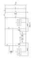
- FIG. 6illustrated is a schematic diagram of an embodiment of a power converter including a bridge rectifier formed with first and second synchronous rectifier switches SR 1 , SR 2 constructed in accordance with the principles of the present invention.
- the bottom two diodes of the bridge rectifier illustrated in FIG. 1are replaced with the first and second synchronous rectifier switches SR 1 , SR 2 and associated controller coupled to a bias voltage source V CC .
- the first and second synchronous rectifier switches SR 1 , SR 2 and the associated controller coupled to the bias voltage source V CCare each illustrated and described hereinabove with reference to the synchronous rectifier switch SR illustrated in FIG. 5 .
- each of the first and second synchronous rectifier switches SR 1 , SR 2is delayed, but a turn off thereof is accelerated by rapid discharge of the respective gate-to-source capacitances.
- a dead time between the gates of the first and second synchronous rectifier switches SR 1 , SR 2is thereby produced, and cross conduction is substantially eliminated.
- the input current spikes illustrated in FIG. 3are substantially attenuated.
- FIG. 7illustrated is a graphical representation of waveforms produced with non-overlapping gate drive signals for first and a second synchronous rectifier switches SR 1 , SR 2 in accordance with the principles of the present invention.
- the first and second synchronous rectifier switches SR 1 , SR 2are coupled in a circuit arrangement wherein a shoot-through current would be produced if both synchronous rectifier switches SR 1 , SR 2 were simultaneously enabled to conduct.
- input current spikes due to diode cross conductionare no longer visible (see waveform 710 ).
- gate drive waveformsare illustrated without overlap (see, e.g., region 720 ) between their high voltage states.
- the input voltage sourceis not presented with brief periodic short circuits, thereby eliminating an unnecessarily high level of electromagnetic interference, and decreasing conduction losses for the bridge rectifier.
- FIG. 8illustrated is a graphical representation demonstrating dead time between the first and second synchronous rectifier switches SR 1 , SR 2 , introduced with respect to FIG. 6 .
- the graphical representationillustrates gate drive waveforms 810 , 820 for gate drive signals for the first and second synchronous rectifier switches SR 1 , SR 2 , respectively, that demonstrate a fast turn off of the first synchronous rectifier switch SR 1 and a turn on with a delay for the second synchronous rectifier switch SR 2 .
- a second diode(diode D 15 in series with the diode D 6 ) is included therein that detects a forward voltage drop across a switch (e.g., the first synchronous rectifier switch SR 1 ).
- a discharge switch Q 3 , diode D 12 , and resistors R 12 , R 15are included in controller for the switch (e.g., the first synchronous rectifier switch SR 1 ) to quickly discharge a gate charge thereof, enabling thereby fast turn off of the switch.
- FIG. 9illustrated is a schematic diagram of an embodiment of a controller for first and second synchronous rectifier switches SR 1 , SR 2 constructed according to the principles of the present invention.
- the controllerincludes first and second lock switches Q 24 , Q 25 coupled to gate terminals of the first and second synchronous rectifier switches SR 1 , SR 2 , respectively, to provide a further mechanism to prevent cross conduction of the first and second synchronous rectifier switches SR 1 , SR 2 .
- the first and second lock switches Q 24 , Q 25form a mutual lock circuit for the first and second synchronous rectifier switches SR 1 , SR 2 , wherein a switched terminal of one of the lock switches (e.g., the first lock switch Q 24 ) is coupled to a control terminal of the other lock switch (e.g., the second lock switch Q 25 ). Accordingly, the gate terminal of the first lock switch Q 24 is cross-coupled to the drain terminal of the second lock switch Q 25 , and the gate terminal of the second lock switch Q 25 is cross-coupled to the drain terminal of first lock switch Q 24 .
- the controller for the switch(e.g., a synchronous rectifier switch) includes an amplifier (e.g., coupled to a bias voltage source) including a plurality of series-coupled diodes configured to produce an input offset voltage therefor and a discharge switch having first and second switched terminals coupled to gate and source terminals, respectively, of the switch and a control terminal coupled to an output of the amplifier.
- the discharge switchis configured to discharge a gate-to-source capacitance of the switch.
- the gate terminal of the switchis coupled to a bias voltage source through a resistor, and/or the gate terminal of the switch is coupled to a bias voltage source through a charge switch with a control terminal coupled to the output of the amplifier.
- the amplifiermay also include an amplifier switch having a base terminal coupled to an input of the amplifier and through the plurality of series-coupled diodes to a drain terminal of the switch, an emitter terminal coupled to the source terminal of the switch, and a collector terminal coupled to the output of the amplifier.
- the input offset voltage produced by the plurality of series-coupled diodesis configured to cause a turn-on delay (e.g., in a range of one microsecond to four milliseconds) for the switch.
- the controllermay further include a mutual lock circuit including a first lock switch and a second lock switch coupled to a gate terminal of a switch and a gate terminal of another switch, respectively, wherein a switched terminal (e.g., drain terminal) of the first lock switch is coupled to a control terminal (e.g., gate terminal) of the second lock switch.
- a mutual lock circuitincluding a first lock switch and a second lock switch coupled to a gate terminal of a switch and a gate terminal of another switch, respectively, wherein a switched terminal (e.g., drain terminal) of the first lock switch is coupled to a control terminal (e.g., gate terminal) of the second lock switch.
- a controller for a power converter and method of operating the same employable with a bridge rectifier having first and second synchronous rectifier switchesincludes an amplifier including an amplifier switch and a plurality of series-coupled diodes configured to produce a threshold voltage to enable a turn-on delay for the first synchronous rectifier switch.
- the turn-on delayis a function of a voltage at a source terminal of the first synchronous rectifier switch being higher than a voltage at a drain terminal of the first synchronous rectifier switch by the threshold voltage.
- the amplifier switchis configured to be turned off when a voltage at the source terminal is higher than a voltage at the drain terminal of the first synchronous rectifier switch by the threshold voltage and a body diode of the first synchronous rectifier switch is forward biased, thereby causing a charge switch to provide a positive bias voltage to the gate terminal of the first synchronous rectifier switch to enable a conductivity thereof.
- the controlleralso includes a discharge switch having first and second switched terminals coupled to gate and source terminals, respectively, of the first synchronous rectifier switch and a control terminal coupled to an output of the amplifier.
- the discharge switchis configured to discharge a gate-to-source capacitance of the first synchronous rectifier switch to enable a turn off thereof.
- the discharge switchis configured to be turned on and discharge the gate-to-source capacitance of the first synchronous rectifier switch when a body diode of the first synchronous rectifier switch is back biased.
- the amplifieris configured to enable the turn-on delay for the first synchronous rectifier switch and the discharge switch is configured to enable the turn off of the first synchronous rectifier switch to substantially eliminate cross conduction with the second synchronous rectifier switch.
- a mutual lock circuitincludes a first lock switch and a second lock switch coupled to a gate terminal of the first and second synchronous rectifier switches, respectively, wherein a switched terminal (e.g., drain terminal) of the first lock switch is coupled to a control terminal (e.g., gate terminal) of the second lock switch.
Landscapes
- Engineering & Computer Science (AREA)
- Power Engineering (AREA)
- Rectifiers (AREA)
- Dc-Dc Converters (AREA)
Abstract
Description
This application claims the benefit of U.S. Provisional Application No. 61/145,657, entitled “Controller for a Synchronous Rectifier Switch and Power Converter Employing the Same,” filed on Jan. 19, 2009, which application is incorporated herein by reference.
The present invention is directed, in general, to power electronics and, more specifically, to controller for a power converter and method of operating the same.
A switched-mode power converter (also referred to as a “power converter” or “regulator”) is a power supply or power processing circuit that converts an input voltage waveform into a specified output voltage waveform. AC-DC power converters convert an alternating current (“ac”) input voltage into a direct current (“dc”) output voltage. Controllers associated with the power converters manage an operation thereof by controlling the conduction periods of power switches employed therein. Generally, the controllers are coupled between an input and output of the power converter in a feedback loop configuration (also referred to as a “control loop” or “closed control loop”).
To produce a dc output voltage, power converters often employ diodes to rectify an ac voltage. The rectifying devices can introduce a power loss component in a power converter due to the forward voltage drop across the diode, particularly in a power converter that produces an output voltage of five volts or less. Schottky diodes, which have a relatively low forward voltage drop, are often employed in low-voltage power converter applications to reduce a diode forward voltage drop. However, passive rectifying devices such as Schottky diodes typically cannot achieve forward voltage drops of less than about 0.35 volts (“V”), and typically cannot sustain a reverse voltage greater than about 60 volts, thereby limiting a conversion efficiency of the power converter.
To achieve an acceptable level of efficiency, power converters often employ rectifying devices that may have forward voltage drops less than about 0.1 volts. To provide such reduction of power loss, an active switch or active semiconductor switch such as a metal-oxide semiconductor field-effect transistor (“MOSFET”), which provides a resistive voltage drop, is often employed to replace a diode. An active semiconductor switch, however, must be periodically driven into conduction and non-conduction modes or states in synchronism with a periodic waveform of an ac voltage (e.g., an ac voltage produced across an input to the power converter). The active semiconductor switches may thereby avoid the higher forward voltage drops inherent in the passive rectifying devices.
A design issue introduced by substituting an active semiconductor switch for a diode is the need to provide a drive signal therefor that is accurately synchronized with the operation of the power converter to control the conduction and non-conduction modes or states of the active semiconductor switches, and that avoids conduction overlap with other semiconductor switches including diodes. An active semiconductor switch substituted for a diode in a power converter is generally referred to as a “synchronous rectifier” or “synchronous rectifier switch.”
A conventional ac-to-dc power converter employs a bridge rectifier to transform an ac sinusoidal input voltage waveform, such as an input voltage waveform produced by an ac mains, into a rectified sinusoidal waveform. Following the bridge rectifier, a power factor correction (“PFC”) circuit converts the rectified sinusoidal waveform into a dc waveform with a dc voltage level higher than the peak voltage of the sinusoidal input voltage. The bridge rectifier is usually constructed with four diodes. Due to the forward voltage drop of the diodes, significant power losses are produced by the diodes.
A bridgeless boost PFC circuit may be employed to address the power loss problem associated with the forward voltage drop of the diodes. As a result, conduction losses of the diodes are reduced. However, a bridgeless boost PFC circuit has several significant remaining problems that limit its application in low-cost, high-volume circuits. On the ac side of the circuit, a two-inductor structure introduced by the circuit causes the output voltage to float with respect to the input line voltage. As a result, the circuit produces a high level of electromagnetic interference (“EMI”) noise. The location of the boost inductor on the ac side makes it difficult to sense the ac line voltage and the inductor current and the control is a more complicated process compared with control schemes used for a simpler boost PFC circuit or boost power converter coupled to a bridge rectifier. As a result, the bridgeless boost PFC circuit has found limited application.
U.S. Pat. No. 6,060,943, entitled “Circuit Simulating a Diode” to Jansen, issued May 9, 2000 and U.S. Pat. No. 6,469,564, entitled “Circuit Simulating a Diode” to Jansen, issued Oct. 22, 2002, which are both incorporated herein by reference, are directed to a circuit that performs the function of a diode to conduct current in one direction with a low forward voltage drop, but block current in the other direction to produce an improved rectification function. When the voltage at a designated anode terminal of the circuit is higher than the voltage at a designated cathode terminal, a forward current flows. When the polarity of the voltage at these designated terminals is reversed, the current is interrupted.
Each of these approaches, however, provides an efficiency and/or a cost limitation that limits or otherwise penalizes the use of a synchronous rectifier in many applications. Accordingly, what is needed in the art is a controller employable with a synchronous rectifier in a power converter and related method that avoid the deficiencies in the prior art.
These and other problems are generally solved or circumvented, and technical advantages are generally achieved, by advantageous embodiments of the present invention, including a controller for a power converter and method of operating the same employable with a bridge rectifier having first and second synchronous rectifier switches. In one embodiment, the controller includes an amplifier configured to enable a turn-on delay for the first synchronous rectifier switch. The controller also includes a discharge switch having first and second switched terminals coupled to gate and source terminals, respectively, of the first synchronous rectifier switch and configured to discharge a gate-to-source capacitance of the first synchronous rectifier switch to enable a turn off thereof.
The foregoing has outlined rather broadly the features and technical advantages of the present invention in order that the detailed description of the invention that follows may be better understood. Additional features and advantages of the invention will be described hereinafter, which form the subject of the claims of the invention. It should be appreciated by those skilled in the art that the conception and specific embodiment disclosed may be readily utilized as a basis for modifying or designing other structures or processes for carrying out the same purposes of the present invention. It should also be realized by those skilled in the art that such equivalent constructions do not depart from the spirit and scope of the invention as set forth in the appended claims.
For a more complete understanding of the present invention, reference is now made to the following descriptions taken in conjunction with the accompanying drawings, in which:
Corresponding numerals and symbols in the different FIGUREs generally refer to corresponding parts unless otherwise indicated, and may not be redescribed in the interest of brevity after the first instance. The FIGUREs are drawn to illustrate the relevant aspects of exemplary embodiments.
The making and using of the present exemplary embodiments are discussed in detail below. It should be appreciated, however, that the present invention provides many applicable inventive concepts that can be embodied in a wide variety of specific contexts. The specific embodiments discussed are merely illustrative of specific ways to make and use the invention, and do not limit the scope of the invention.
The present invention will be described with respect to exemplary embodiments in a specific context, namely, a controller for a switch such as a synchronous rectifier switch with a delay turn on thereof, and a method of operating the same. While the principles of the present invention will be described in the environment of a power converter, any application that may benefit from a controller such as a power amplifier or a motor controller is well within the broad scope of the present invention. Additionally, while the principles of the present invention will be described with respect to field-effect transistors including gate, source and drain terminals, the principles are equally applicable to any types of switches having control and switched terminals.
Turning now toFIG. 1 , illustrated is a schematic diagram of an embodiment of a power converter (e.g., an ac-to-dc power converter) including abridge rectifier 110 coupled to a boost power converter120 (also referred to as a “boost power train”) that provides an environment for application of the principles of the present invention. Thebridge rectifier 110 includes a plurality of bridge diodes D1, D2, D3, D4 configured as a four-diode bridge rectifier coupled to an ac input voltage source (designated “V1”) to produce a rectified waveform that is operative as an input voltage for theboost power converter 120. Theboost power converter 120 includes boost inductor L1 and boost power switch Q1. The boost power switch Q1, illustrated inFIG. 1 as an n-channel MOSFET, is controlled to conduct intermittently with a duty cycle D to produce a current in the boost inductor L1 that is intermittently conducted to a boost diode D5 with a complementary duty cycle1-D. The boost diode D5 rectifies the inductor current to produce a dc voltage across an output filter capacitor C1. The resistor RLOADrepresents a load connected to the output of the ac-to-dc power converter.
A significant source of power loss in the power converter illustrated inFIG. 1 is the forward voltage drop of the bridge diodes D1, D2, D3, D4. To address this power loss problem, the bridge diodes D1, D2, D3, D4 may be replaced with active switches or active semiconductor switches functioning as synchronous rectifiers or synchronous rectifier switches with a substantially smaller forward voltage drop than passive diodes. An issue in the design of synchronous rectifiers formed with active switches is cross conduction between a pair of synchronous rectifiers, thereby presenting a further power loss problem.
Turning now toFIG. 2 , illustrated is a schematic diagram of an embodiment of a power converter (e.g., an ac-dc power converter) including first and second synchronous rectifier switches SR1, SR2 in a bridge rectifier constructed according to the principles of the present invention. A conventional synchronous rectifier arrangement cannot be employed to replace the diodes in the bridge rectifier because a conventional synchronous rectifier arrangement (see, e.g., U.S. Pat. No. 6,469,564 to Jansen) uses a diode and a transistor base-emitter p-n junction as two voltage-sensing inputs to determine when the active switch employed as the synchronous rectifier is enabled to conduct. As a result, a conventional synchronous rectifier arrangement is principally used when a single diode is employed, but suffers degradation of power converter efficiency when coupled to another active switch. When a conventional synchronous rectifier arrangement is used to replace two or more diodes in a bridge rectifier (top two diodes, bottom two diodes, or upper and lower branch diodes as illustrated inFIG. 1 ), cross conduction between the two diodes occurs during a brief period of time when both diodes are enabled to conduct. When one synchronous rectifier switch operative as a diode turns on and another turns off, a mismatch of the diode and base emitter p-n junction of the synchronous rectifier switch and the reverse recovery charge of the diode result in overlapping control terminal signals (e.g., gate drive signals), or at least not separated gate drive signals, for the two active switches (e.g., MOSFETs) employed as the synchronous rectifier switches.
Turning now toFIG. 3 , illustrated is a graphical representation of waveforms produced with overlapping gate drive signals for first and second synchronous rectifier switches SR1, SR2. The first and second synchronous rectifier switches SR1, SR2 are coupled in a series arrangement wherein a shoot-through current is produced when both synchronous rectifier switches SR1, SR2 are simultaneously enabled to conduct. In the top portion ofFIG. 3 , inputcurrent spikes 310 are illustrated every 10 milliseconds (“ms”) for a 50 hertz (“Hz”) input ac voltage due to diode cross conduction. In the middle and lower portions ofFIG. 3 , gate drive waveforms are illustrated that enable conduction of the first and second synchronous rectifier switches SR1, SR2 without a period of separation between their high gate drive voltage levels (also referred to as gate drive signal overlap320). As a consequence, the input voltage source is briefly coupled to a short circuit every half line cycle that produces a spike in current from the input voltage source. Such circuit operation generally results in a high level of electromagnetic interference (“EMI”), and increases conduction losses for the bridge rectifier.
Turning now toFIG. 4 , illustrated is a graphical representation of waveforms produced with gate drive signals for first and second synchronous rectifier switches SR1, SR2. As illustrated inFIG. 4 , a period of overlap is shown for conventional synchronous rectifier designs during which both synchronous rectifier switches SR1, SR2 are enabled to conduct (first synchronous rectifiergate drive signal 410 and second synchronous rectifiergate drive signal 420 provide an overlap430), producing thereby a spike in input current from the input voltage source. By replacing the diodes D2, D4 of the bridge rectifier ofFIG. 1 with the first and second synchronous rectifier switches SR1, SR2 in accordance with the principles of the present invention, cross conduction therebetween may be substantially reduced.
Turning now toFIG. 5 , illustrated is a schematic diagram of an embodiment of a controller for a switch (e.g., a synchronous rectifier switch SR) constructed according to the principles of the present invention. The controller illustrated inFIG. 5 includes elements that charge or discharge a gate-to-source capacitance of the synchronous rectifier switch SR. Charging and discharging gate-to-source capacitance is generally an obstacle for quickly enabling or disabling conductivity of an active switch such as a MOSFET employed as the synchronous rectifier switch SR. Quickly disabling conductivity of the synchronous rectifier switch SR is important for eliminating (or substantially eliminating) cross conduction thereof with another active switch in a power converter.
A controller for the synchronous rectifier switch SR includes anamplifier 510 with a threshold voltage produced in accordance with a plurality of series-coupled diodes D6, D15. The controller further includes a discharge switch Q3 (e.g., a pnp transistor) with switched terminals coupled between the source and gate terminals of the synchronous rectifier switch SR and a control terminal coupled to an output of theamplifier 510. The discharge switch Q3 is formed with emitter (designated “e”), base (designated “b”), and collector (designated “c”) terminals. The synchronous rectifier switch SR is formed with source (designated “s”), gate (designated “g”), and drain (designated “d”) terminals. The emitter of the discharge switch Q3 is connected to the gate of the synchronous rectifier switch SR, and the collector of discharge switch Q3 is connected to the source of synchronous rectifier switch SR. As a result, when a body diode D30 of synchronous rectifier switch SR is back biased, voltage of a node K is higher than voltage of a node A, and an amplifier switch (e.g., a npn transistor) Q12 turns on due to current flowing into its base from a bias voltage source VCCthrough a resistor R16. A charge switch (e.g., transistor) Q11 is turned off and the discharge switch Q3 is turned on. Turning on the discharge switch Q3, which has its emitter and collector terminals connected to the gate and source terminals, respectively, of the synchronous rectifier switch SR, causes the gate charge of the synchronous rectifier switch SR to be quickly discharged, enabling thereby fast turn off of the synchronous rectifier switch SR. Thus, a discharge switch Q3 coupled to terminals of a synchronous rectifier switch SR is configured to enable the quick discharge of a gate-to-source capacitance thereof in response to a back biased condition of the body diode D30 of the synchronous rectifier switch SR.
When the body diode D30 of synchronous rectifier power switch SR is forward biased, and voltage of the node K becomes sufficiently lower than voltage of the node A, the amplifier switch Q12 turns off. The diodes D6, D15 provide a threshold for the voltage of the node K being lower than the voltage of the node A to turn off the amplifier switch Q12, thereby introducing a turn-on delay for the synchronous rectifier switch SR. Turning off the amplifier switch Q12 enables a resistor R14 to provide a bias current from the bias voltage source VCCto the base of the charge switch Q11 that is thereby turned on. Turning on the charge switch Q11 provides a positive bias voltage from the bias voltage source VCCthrough a diode D12 to the gate of synchronous rectifier switch SR, enabling it to conduct. Note that voltage of the node A should be higher than voltage of the node K plus a threshold voltage Vthresholdto induce the synchronous rectifier switch SR turn on. A turn-on delay is produced by causing voltage of the node A to be higher than voltage of the node K plus a threshold voltage Vthreshold. Thus, a charge switch Q11 coupled to terminals of a synchronous rectifier switch SR is configured to charge a gate-to-source capacitance thereof after a delay in response to a forward biased condition of the synchronous rectifier switch SR. The remaining circuit elements illustrated inFIG. 5 such as resistors R12, R15, R17 are included to provide proper levels of voltages and currents for reliable operation of the controller, applying considerations for specific devices such as required voltage and current levels for proper controller operation.
For the controller illustrated inFIG. 5 , the voltage VAof node A is equal to the voltage VMof node M minus the base-emitter p-n junction forward voltage drop of the amplifier switch Q12. The voltage VKof node K is the voltage VMof node M minus the sum of the p-n junction forward voltage drops of series-coupled diodes D15, D6. The voltage Vthresholdis the threshold voltage of the synchronous rectifier switch SR. The voltage VbeQ12is the base-emitter voltage of the amplifier switch Q12. The voltage VfD15is the forward-diode voltage of diode D15. The voltage VfD6is the forward-diode voltage of diode D6.
VA=VM−VbeQ12 (1)
VK=VM−VfD15−VfD6 (2)
VA=VK+Vthreshold (3)
Vthreshold=VfD15+VfD6−VbeQ12 (4)
VA=VM−VbeQ12 (1)
VK=VM−VfD15−VfD6 (2)
VA=VK+Vthreshold (3)
Vthreshold=VfD15+VfD6−VbeQ12 (4)
As opposed to the circuits described by Jansen in U.S. Pat. No. 6,060,943 and U.S. Pat. No. 6,469,564, the controller for the synchronous rectifier switch SR introduced herein has a turn-on delay generated by the series-coupled diodes D6, D15, preferably in the range of one microsecond (“μs”) to four milliseconds (“ms”). In the circuits described by Jansen, when voltage of node A is higher than voltage of node K, a current flows from node A to node K. However, inFIG. 5 , the voltage of node A should be sufficiently higher than voltage of node K plus the threshold voltage Vthresholdto make the synchronous rectifier switch SR turn on, thus generating a turn-on delay.
Turning now toFIG. 6 , illustrated is a schematic diagram of an embodiment of a power converter including a bridge rectifier formed with first and second synchronous rectifier switches SR1, SR2 constructed in accordance with the principles of the present invention. In the bridge rectifier illustrated inFIG. 6 , the bottom two diodes of the bridge rectifier illustrated inFIG. 1 are replaced with the first and second synchronous rectifier switches SR1, SR2 and associated controller coupled to a bias voltage source VCC. The first and second synchronous rectifier switches SR1, SR2 and the associated controller coupled to the bias voltage source VCCare each illustrated and described hereinabove with reference to the synchronous rectifier switch SR illustrated inFIG. 5 . The turn on of each of the first and second synchronous rectifier switches SR1, SR2 is delayed, but a turn off thereof is accelerated by rapid discharge of the respective gate-to-source capacitances. A dead time between the gates of the first and second synchronous rectifier switches SR1, SR2 is thereby produced, and cross conduction is substantially eliminated. As a result, the input current spikes illustrated inFIG. 3 are substantially attenuated.
Turning now toFIG. 7 , illustrated is a graphical representation of waveforms produced with non-overlapping gate drive signals for first and a second synchronous rectifier switches SR1, SR2 in accordance with the principles of the present invention. The first and second synchronous rectifier switches SR1, SR2 are coupled in a circuit arrangement wherein a shoot-through current would be produced if both synchronous rectifier switches SR1, SR2 were simultaneously enabled to conduct. In the top portion ofFIG. 7 , input current spikes due to diode cross conduction are no longer visible (see waveform710). In the middle and lower portions ofFIG. 7 , gate drive waveforms are illustrated without overlap (see, e.g., region720) between their high voltage states. As a consequence, the input voltage source is not presented with brief periodic short circuits, thereby eliminating an unnecessarily high level of electromagnetic interference, and decreasing conduction losses for the bridge rectifier.
Turning now toFIG. 8 , illustrated is a graphical representation demonstrating dead time between the first and second synchronous rectifier switches SR1, SR2, introduced with respect toFIG. 6 . The graphical representation illustratesgate drive waveforms
Turning now toFIG. 9 , illustrated is a schematic diagram of an embodiment of a controller for first and second synchronous rectifier switches SR1, SR2 constructed according to the principles of the present invention. The controller includes first and second lock switches Q24, Q25 coupled to gate terminals of the first and second synchronous rectifier switches SR1, SR2, respectively, to provide a further mechanism to prevent cross conduction of the first and second synchronous rectifier switches SR1, SR2. The first and second lock switches Q24, Q25 form a mutual lock circuit for the first and second synchronous rectifier switches SR1, SR2, wherein a switched terminal of one of the lock switches (e.g., the first lock switch Q24) is coupled to a control terminal of the other lock switch (e.g., the second lock switch Q25). Accordingly, the gate terminal of the first lock switch Q24 is cross-coupled to the drain terminal of the second lock switch Q25, and the gate terminal of the second lock switch Q25 is cross-coupled to the drain terminal of first lock switch Q24. By cross-coupling the gate and drain terminals of the first and second lock switches Q24, Q25, only one can be switched on at the same time (i.e., only one can sustain a substantial positive voltage at its drain terminal). However, cross coupling the gate and drain terminals of the first and second lock switches Q24, Q25, still allows both switches to be off at the same time. The remainder of the controller illustrated inFIG. 9 is formed with analogous components illustrated and described with reference toFIG. 5 .
Thus, a controller for a switch has been introduced herein. In one embodiment, the controller for the switch (e.g., a synchronous rectifier switch) includes an amplifier (e.g., coupled to a bias voltage source) including a plurality of series-coupled diodes configured to produce an input offset voltage therefor and a discharge switch having first and second switched terminals coupled to gate and source terminals, respectively, of the switch and a control terminal coupled to an output of the amplifier. The discharge switch is configured to discharge a gate-to-source capacitance of the switch. In related embodiments, the gate terminal of the switch is coupled to a bias voltage source through a resistor, and/or the gate terminal of the switch is coupled to a bias voltage source through a charge switch with a control terminal coupled to the output of the amplifier. The amplifier may also include an amplifier switch having a base terminal coupled to an input of the amplifier and through the plurality of series-coupled diodes to a drain terminal of the switch, an emitter terminal coupled to the source terminal of the switch, and a collector terminal coupled to the output of the amplifier. The input offset voltage produced by the plurality of series-coupled diodes is configured to cause a turn-on delay (e.g., in a range of one microsecond to four milliseconds) for the switch. When employed with multiples switches, the controller may further include a mutual lock circuit including a first lock switch and a second lock switch coupled to a gate terminal of a switch and a gate terminal of another switch, respectively, wherein a switched terminal (e.g., drain terminal) of the first lock switch is coupled to a control terminal (e.g., gate terminal) of the second lock switch.
In a related embodiment, a controller for a power converter and method of operating the same employable with a bridge rectifier having first and second synchronous rectifier switches has been introduced herein. The controller includes an amplifier including an amplifier switch and a plurality of series-coupled diodes configured to produce a threshold voltage to enable a turn-on delay for the first synchronous rectifier switch. The turn-on delay is a function of a voltage at a source terminal of the first synchronous rectifier switch being higher than a voltage at a drain terminal of the first synchronous rectifier switch by the threshold voltage. Also, the amplifier switch is configured to be turned off when a voltage at the source terminal is higher than a voltage at the drain terminal of the first synchronous rectifier switch by the threshold voltage and a body diode of the first synchronous rectifier switch is forward biased, thereby causing a charge switch to provide a positive bias voltage to the gate terminal of the first synchronous rectifier switch to enable a conductivity thereof.
The controller also includes a discharge switch having first and second switched terminals coupled to gate and source terminals, respectively, of the first synchronous rectifier switch and a control terminal coupled to an output of the amplifier. The discharge switch is configured to discharge a gate-to-source capacitance of the first synchronous rectifier switch to enable a turn off thereof. The discharge switch is configured to be turned on and discharge the gate-to-source capacitance of the first synchronous rectifier switch when a body diode of the first synchronous rectifier switch is back biased. Additionally, the amplifier is configured to enable the turn-on delay for the first synchronous rectifier switch and the discharge switch is configured to enable the turn off of the first synchronous rectifier switch to substantially eliminate cross conduction with the second synchronous rectifier switch. Also, the gate terminal of the first synchronous rectifier switch is coupled to a bias voltage source through a charge switch with a control terminal coupled to the output of the amplifier, and the gate terminal of the first synchronous rectifier switch is coupled to a bias voltage source through a resistor. In accordance with the first and second synchronous rectifier switches, a mutual lock circuit includes a first lock switch and a second lock switch coupled to a gate terminal of the first and second synchronous rectifier switches, respectively, wherein a switched terminal (e.g., drain terminal) of the first lock switch is coupled to a control terminal (e.g., gate terminal) of the second lock switch.
Those skilled in the art should understand that the previously described embodiments of a synchronous rectifier power switch and related methods of operating the same are submitted for illustrative purposes only. In addition, various power converter topologies are well within the broad scope of the present invention. While the synchronous rectifier power switch has been described in the environment of a flyback power converter, it may also be applied to other systems such as, without limitation, a power amplifier and a motor controller.
For a better understanding of power converters, see “Modern DC-to-DC Power Switch-mode Power Converter Circuits,” by Rudolph P. Severns and Gordon Bloom, Van Nostrand Reinhold Company, New York, N.Y. (1985) and “Principles of Power Electronics,” by J. G. Kassakian, M. F. Schlecht and G. C. Verghese, Addison-Wesley (1991). The aforementioned references are incorporated herein by reference in their entirety.
Also, although the present invention and its advantages have been described in detail, it should be understood that various changes, substitutions and alterations can be made herein without departing from the spirit and scope of the invention as defined by the appended claims. For example, many of the processes discussed above can be implemented in different methodologies and replaced by other processes, or a combination thereof.
Moreover, the scope of the present application is not intended to be limited to the particular embodiments of the process, machine, manufacture, composition of matter, means, methods, and steps described in the specification. As one of ordinary skill in the art will readily appreciate from the disclosure of the present invention, processes, machines, manufacture, compositions of matter, means, methods, or steps, presently existing or later to be developed, that perform substantially the same function or achieve substantially the same result as the corresponding embodiments described herein may be utilized according to the present invention. Accordingly, the appended claims are intended to include within their scope such processes, machines, manufacture, compositions of matter, means, methods, or steps.
Claims (20)
1. A controller employable with a bridge rectifier having first and second synchronous rectifier switches, comprising:
an amplifier configured to enable a turn-on delay with a plurality of series-coupled diodes for said first synchronous rectifier switch;
a discharge switch having a control terminal coupled to an output of said amplifier via a charge switch, and first and second switched terminals coupled to gate and source terminals, respectively, of said first synchronous rectifier switch and configured to discharge a gate-to-source capacitance of said first synchronous rectifier switch to enable a turn off thereof; and
a mutual lock circuit including a first lock switch and a second lock switch coupled to said gate terminal of said first synchronous rectifier switch and a gate terminal of said second synchronous rectifier switch, respectively, wherein a switched terminal of said first lock switch is cross-coupled to a control terminal of said second lock switch, a switched terminal of said second lock switch is cross-coupled to a control terminal of said first lock switch, and said first lock switch is parallel-coupled to said discharge switch.
2. The controller as recited inclaim 1 wherein said amplifier is configured to produce a threshold voltage to enable said turn-on delay for said first synchronous rectifier switch.
3. The controller as recited inclaim 1 wherein said amplifier is configured to produce a threshold voltage in accordance with said plurality of series-coupled diodes to enable said turn-on delay for said first synchronous rectifier switch.
4. The controller as recited inclaim 1 wherein said turn-on delay is a function of a voltage at said source terminal being higher than a voltage at a drain terminal of said first synchronous rectifier switch by a threshold voltage.
5. The controller as recited inclaim 1 wherein an amplifier switch is configured to be turned off when a voltage at said source terminal is higher than a voltage at a drain terminal of said first synchronous rectifier switch by a threshold voltage and a body diode of said first synchronous rectifier switch is forward biased, thereby causing said charge switch to provide a positive bias voltage to said gate terminal of said first synchronous rectifier switch to enable a conductivity thereof.
6. The controller as recited inclaim 1 , further comprising:
another amplifier configured to enable a turn-on delay with another plurality of series-coupled diodes for said second synchronous rectifier switch; and
another discharge switch having a control terminal coupled to an output of said another amplifier via another charge switch, and first and second switched terminals coupled to gate and source terminals, respectively, of said second synchronous rectifier switch and configured to discharge a gate-to-source capacitance of said second synchronous rectifier switch to enable a turn off thereof.
7. The controller as recited inclaim 1 wherein said discharge switch is configured to be turned on and discharge said gate-to-source capacitance of said first synchronous rectifier switch when a body diode of said first synchronous rectifier switch is back biased.
8. The controller as recited inclaim 1 wherein said amplifier is configured to enable said turn-on delay for said first synchronous rectifier switch and said discharge switch is configured to enable said turn off of said first synchronous rectifier switch to substantially eliminate cross conduction with said second synchronous rectifier switch.
9. The controller as recited inclaim 1 wherein said charge switch is configured to provide a positive bias voltage from a bias voltage source through a diode to said gate terminal of said first synchronous rectifier switch to enable a conductivity thereof.
10. The controller as recited inclaim 1 wherein said discharge switch is a bipolar transistor.
11. A method of operating a controller employable with a bridge rectifier having first and second synchronous rectifier switches, comprising:
enabling a turn-on delay for said first synchronous rectifier switch with a plurality of series-coupled diodes of an amplifier;
discharging a gate-to-source capacitance of said first synchronous rectifier switch with a discharge switch having a control terminal coupled to an output of said amplifier via a charge switch, and first and second switched terminals coupled to gate and source terminals, respectively, of said first synchronous rectifier switch to enable a turn off of said first synchronous rectifier switch; and
reducing cross conduction between said first and second synchronous rectifier switches with a mutual lock circuit including a first lock switch and a second lock switch coupled to said gate terminal of said first synchronous rectifier switch and a gate terminal of said second synchronous rectifier switch, respectively, wherein a switched terminal of said first lock switch is cross-coupled to a control terminal of said second lock switch, a switched terminal of said second lock switch is cross-coupled to a control terminal of said first lock switch, and said first lock switch is parallel-coupled to said discharge switch.
12. The method as recited inclaim 11 wherein said enabling comprises producing a threshold voltage in accordance with said plurality of series-coupled diodes.
13. The method as recited inclaim 11 wherein said enabling comprises turning off an amplifier switch when a voltage at said source terminal is higher than a voltage at a drain terminal of said first synchronous rectifier switch by a threshold voltage and a body diode of said first synchronous rectifier switch is forward biased, thereby causing said charge switch to provide a positive bias voltage to said gate terminal of said first synchronous rectifier switch to enable a conductivity thereof.
14. The method as recited inclaim 11 wherein discharging comprises turning on said discharge switch and discharging said gate-to-source capacitance of said first synchronous rectifier switch when a body diode of said first synchronous rectifier switch is back biased.
15. A power converter, comprising:
a bridge rectifier having first and second synchronous rectifier switches; and
a controller, including:
an amplifier configured to enable a turn-on delay with a plurality of series-coupled diodes for said first synchronous rectifier switch,
a discharge switch having a control terminal coupled to an output of said amplifier via a charge switch, and first and second switched terminals coupled to gate and source terminals, respectively, of said first synchronous rectifier switch and configured to discharge a gate-to-source capacitance of said first synchronous rectifier switch to enable a turn off thereof, and
a mutual lock circuit including a first lock switch and a second lock switch coupled to said gate terminal of said first synchronous rectifier switch and a gate terminal of said second synchronous rectifier switch, respectively, wherein a switched terminal of said first lock switch is cross-coupled to a control terminal of said second lock switch, a switched terminal of said second lock switch is cross-coupled to a control terminal of said first lock switch, and said first lock switch is parallel-coupled to said discharge switch.
16. The power converter as recited inclaim 15 wherein said amplifier is configured to produce a threshold voltage in accordance with said plurality of series-coupled diodes to enable said turn-on delay for said first synchronous rectifier switch.
17. The power converter as recited inclaim 15 wherein an amplifier switch is configured to be turned off when a voltage at said source terminal is higher than a voltage at a drain terminal of said first synchronous rectifier switch by a threshold voltage and a body diode of said first synchronous rectifier switch is forward biased, thereby causing said charge switch to provide a positive bias voltage to said gate terminal of said first synchronous rectifier switch to enable a conductivity thereof.
18. The power converter as recited inclaim 15 wherein said discharge switch is configured to be turned on and discharge said gate-to-source capacitance of said first synchronous rectifier switch when a body diode of said first synchronous rectifier switch is back biased.
19. The power converter as recited inclaim 15 wherein said amplifier is configured to enable said turn-on delay for said first synchronous rectifier switch and said discharge switch is configured to enable said turn off of said first synchronous rectifier switch to substantially eliminate cross conduction with said second synchronous rectifier switch.
20. The power converter as recited inclaim 15 wherein said charge switch is configured to provide a positive bias voltage from a bias voltage source through a diode to said gate terminal of said first synchronous rectifier switch to enable a conductivity thereof.
Priority Applications (1)
| Application Number | Priority Date | Filing Date | Title |
|---|---|---|---|
| US12/689,881US9088216B2 (en) | 2009-01-19 | 2010-01-19 | Controller for a synchronous rectifier switch |
Applications Claiming Priority (2)
| Application Number | Priority Date | Filing Date | Title |
|---|---|---|---|
| US14565709P | 2009-01-19 | 2009-01-19 | |
| US12/689,881US9088216B2 (en) | 2009-01-19 | 2010-01-19 | Controller for a synchronous rectifier switch |
Publications (2)
| Publication Number | Publication Date |
|---|---|
| US20100188876A1 US20100188876A1 (en) | 2010-07-29 |
| US9088216B2true US9088216B2 (en) | 2015-07-21 |
Family
ID=42340123
Family Applications (1)
| Application Number | Title | Priority Date | Filing Date |
|---|---|---|---|
| US12/689,881Active2031-12-14US9088216B2 (en) | 2009-01-19 | 2010-01-19 | Controller for a synchronous rectifier switch |
Country Status (3)
| Country | Link |
|---|---|
| US (1) | US9088216B2 (en) |
| CN (1) | CN102342008B (en) |
| WO (1) | WO2010083514A1 (en) |
Cited By (195)
| Publication number | Priority date | Publication date | Assignee | Title |
|---|---|---|---|---|
| US20150326143A1 (en)* | 2014-05-07 | 2015-11-12 | Energous Corporation | Synchronous Rectifier Design for Wireless Power Receiver |
| US9246391B2 (en) | 2010-01-22 | 2016-01-26 | Power Systems Technologies Ltd. | Controller for providing a corrected signal to a sensed peak current through a circuit element of a power converter |
| US9300206B2 (en) | 2013-11-15 | 2016-03-29 | Power Systems Technologies Ltd. | Method for estimating power of a power converter |
| US20170244333A1 (en)* | 2016-02-22 | 2017-08-24 | Fairchild Semiconductor Corporation | Gate pre-positioning for fast turn-off of synchronous rectifier |
| US9787103B1 (en) | 2013-08-06 | 2017-10-10 | Energous Corporation | Systems and methods for wirelessly delivering power to electronic devices that are unable to communicate with a transmitter |
| US9793758B2 (en) | 2014-05-23 | 2017-10-17 | Energous Corporation | Enhanced transmitter using frequency control for wireless power transmission |
| US9800172B1 (en) | 2014-05-07 | 2017-10-24 | Energous Corporation | Integrated rectifier and boost converter for boosting voltage received from wireless power transmission waves |
| US9800080B2 (en) | 2013-05-10 | 2017-10-24 | Energous Corporation | Portable wireless charging pad |
| US9806564B2 (en) | 2014-05-07 | 2017-10-31 | Energous Corporation | Integrated rectifier and boost converter for wireless power transmission |
| US9812890B1 (en) | 2013-07-11 | 2017-11-07 | Energous Corporation | Portable wireless charging pad |
| US9819230B2 (en) | 2014-05-07 | 2017-11-14 | Energous Corporation | Enhanced receiver for wireless power transmission |
| US9825674B1 (en) | 2014-05-23 | 2017-11-21 | Energous Corporation | Enhanced transmitter that selects configurations of antenna elements for performing wireless power transmission and receiving functions |
| US9824815B2 (en) | 2013-05-10 | 2017-11-21 | Energous Corporation | Wireless charging and powering of healthcare gadgets and sensors |
| US9831718B2 (en) | 2013-07-25 | 2017-11-28 | Energous Corporation | TV with integrated wireless power transmitter |
| US9838083B2 (en) | 2014-07-21 | 2017-12-05 | Energous Corporation | Systems and methods for communication with remote management systems |
| US9843201B1 (en) | 2012-07-06 | 2017-12-12 | Energous Corporation | Wireless power transmitter that selects antenna sets for transmitting wireless power to a receiver based on location of the receiver, and methods of use thereof |
| US9843213B2 (en) | 2013-08-06 | 2017-12-12 | Energous Corporation | Social power sharing for mobile devices based on pocket-forming |
| US9843229B2 (en) | 2013-05-10 | 2017-12-12 | Energous Corporation | Wireless sound charging and powering of healthcare gadgets and sensors |
| US9847677B1 (en) | 2013-10-10 | 2017-12-19 | Energous Corporation | Wireless charging and powering of healthcare gadgets and sensors |
| US9847669B2 (en) | 2013-05-10 | 2017-12-19 | Energous Corporation | Laptop computer as a transmitter for wireless charging |
| US9847679B2 (en) | 2014-05-07 | 2017-12-19 | Energous Corporation | System and method for controlling communication between wireless power transmitter managers |
| US9853458B1 (en) | 2014-05-07 | 2017-12-26 | Energous Corporation | Systems and methods for device and power receiver pairing |
| US9853485B2 (en) | 2015-10-28 | 2017-12-26 | Energous Corporation | Antenna for wireless charging systems |
| US9853692B1 (en) | 2014-05-23 | 2017-12-26 | Energous Corporation | Systems and methods for wireless power transmission |
| US9859797B1 (en) | 2014-05-07 | 2018-01-02 | Energous Corporation | Synchronous rectifier design for wireless power receiver |
| US9859756B2 (en) | 2012-07-06 | 2018-01-02 | Energous Corporation | Transmittersand methods for adjusting wireless power transmission based on information from receivers |
| US9859758B1 (en) | 2014-05-14 | 2018-01-02 | Energous Corporation | Transducer sound arrangement for pocket-forming |
| US9866279B2 (en) | 2013-05-10 | 2018-01-09 | Energous Corporation | Systems and methods for selecting which power transmitter should deliver wireless power to a receiving device in a wireless power delivery network |
| US9871301B2 (en) | 2014-07-21 | 2018-01-16 | Energous Corporation | Integrated miniature PIFA with artificial magnetic conductor metamaterials |
| US9871398B1 (en) | 2013-07-01 | 2018-01-16 | Energous Corporation | Hybrid charging method for wireless power transmission based on pocket-forming |
| US9871387B1 (en) | 2015-09-16 | 2018-01-16 | Energous Corporation | Systems and methods of object detection using one or more video cameras in wireless power charging systems |
| US9876394B1 (en) | 2014-05-07 | 2018-01-23 | Energous Corporation | Boost-charger-boost system for enhanced power delivery |
| US9876648B2 (en) | 2014-08-21 | 2018-01-23 | Energous Corporation | System and method to control a wireless power transmission system by configuration of wireless power transmission control parameters |
| US9876379B1 (en) | 2013-07-11 | 2018-01-23 | Energous Corporation | Wireless charging and powering of electronic devices in a vehicle |
| US9876536B1 (en) | 2014-05-23 | 2018-01-23 | Energous Corporation | Systems and methods for assigning groups of antennas to transmit wireless power to different wireless power receivers |
| US9882395B1 (en) | 2014-05-07 | 2018-01-30 | Energous Corporation | Cluster management of transmitters in a wireless power transmission system |
| US9882394B1 (en) | 2014-07-21 | 2018-01-30 | Energous Corporation | Systems and methods for using servers to generate charging schedules for wireless power transmission systems |
| US9882427B2 (en) | 2013-05-10 | 2018-01-30 | Energous Corporation | Wireless power delivery using a base station to control operations of a plurality of wireless power transmitters |
| US9887584B1 (en) | 2014-08-21 | 2018-02-06 | Energous Corporation | Systems and methods for a configuration web service to provide configuration of a wireless power transmitter within a wireless power transmission system |
| US9887739B2 (en) | 2012-07-06 | 2018-02-06 | Energous Corporation | Systems and methods for wireless power transmission by comparing voltage levels associated with power waves transmitted by antennas of a plurality of antennas of a transmitter to determine appropriate phase adjustments for the power waves |
| US9893555B1 (en) | 2013-10-10 | 2018-02-13 | Energous Corporation | Wireless charging of tools using a toolbox transmitter |
| US9893538B1 (en) | 2015-09-16 | 2018-02-13 | Energous Corporation | Systems and methods of object detection in wireless power charging systems |
| US9891669B2 (en) | 2014-08-21 | 2018-02-13 | Energous Corporation | Systems and methods for a configuration web service to provide configuration of a wireless power transmitter within a wireless power transmission system |
| US9893768B2 (en) | 2012-07-06 | 2018-02-13 | Energous Corporation | Methodology for multiple pocket-forming |
| US9893535B2 (en) | 2015-02-13 | 2018-02-13 | Energous Corporation | Systems and methods for determining optimal charging positions to maximize efficiency of power received from wirelessly delivered sound wave energy |
| US9893554B2 (en) | 2014-07-14 | 2018-02-13 | Energous Corporation | System and method for providing health safety in a wireless power transmission system |
| US9899861B1 (en) | 2013-10-10 | 2018-02-20 | Energous Corporation | Wireless charging methods and systems for game controllers, based on pocket-forming |
| US9899744B1 (en) | 2015-10-28 | 2018-02-20 | Energous Corporation | Antenna for wireless charging systems |
| US9900057B2 (en) | 2012-07-06 | 2018-02-20 | Energous Corporation | Systems and methods for assigning groups of antenas of a wireless power transmitter to different wireless power receivers, and determining effective phases to use for wirelessly transmitting power using the assigned groups of antennas |
| US9899873B2 (en) | 2014-05-23 | 2018-02-20 | Energous Corporation | System and method for generating a power receiver identifier in a wireless power network |
| US9906065B2 (en) | 2012-07-06 | 2018-02-27 | Energous Corporation | Systems and methods of transmitting power transmission waves based on signals received at first and second subsets of a transmitter's antenna array |
| US9906275B2 (en) | 2015-09-15 | 2018-02-27 | Energous Corporation | Identifying receivers in a wireless charging transmission field |
| US9912199B2 (en) | 2012-07-06 | 2018-03-06 | Energous Corporation | Receivers for wireless power transmission |
| US9917477B1 (en) | 2014-08-21 | 2018-03-13 | Energous Corporation | Systems and methods for automatically testing the communication between power transmitter and wireless receiver |
| US9923386B1 (en) | 2012-07-06 | 2018-03-20 | Energous Corporation | Systems and methods for wireless power transmission by modifying a number of antenna elements used to transmit power waves to a receiver |
| US9935482B1 (en) | 2014-02-06 | 2018-04-03 | Energous Corporation | Wireless power transmitters that transmit at determined times based on power availability and consumption at a receiving mobile device |
| US9941747B2 (en) | 2014-07-14 | 2018-04-10 | Energous Corporation | System and method for manually selecting and deselecting devices to charge in a wireless power network |
| US9941707B1 (en) | 2013-07-19 | 2018-04-10 | Energous Corporation | Home base station for multiple room coverage with multiple transmitters |
| US9939864B1 (en) | 2014-08-21 | 2018-04-10 | Energous Corporation | System and method to control a wireless power transmission system by configuration of wireless power transmission control parameters |
| US9941754B2 (en) | 2012-07-06 | 2018-04-10 | Energous Corporation | Wireless power transmission with selective range |
| US9941752B2 (en) | 2015-09-16 | 2018-04-10 | Energous Corporation | Systems and methods of object detection in wireless power charging systems |
| US9948135B2 (en) | 2015-09-22 | 2018-04-17 | Energous Corporation | Systems and methods for identifying sensitive objects in a wireless charging transmission field |
| US9954374B1 (en) | 2014-05-23 | 2018-04-24 | Energous Corporation | System and method for self-system analysis for detecting a fault in a wireless power transmission Network |
| US9967743B1 (en) | 2013-05-10 | 2018-05-08 | Energous Corporation | Systems and methods for using a transmitter access policy at a network service to determine whether to provide power to wireless power receivers in a wireless power network |
| US9965009B1 (en) | 2014-08-21 | 2018-05-08 | Energous Corporation | Systems and methods for assigning a power receiver to individual power transmitters based on location of the power receiver |
| US9966784B2 (en) | 2014-06-03 | 2018-05-08 | Energous Corporation | Systems and methods for extending battery life of portable electronic devices charged by sound |
| US9966765B1 (en) | 2013-06-25 | 2018-05-08 | Energous Corporation | Multi-mode transmitter |
| US9973021B2 (en) | 2012-07-06 | 2018-05-15 | Energous Corporation | Receivers for wireless power transmission |
| US9973008B1 (en) | 2014-05-07 | 2018-05-15 | Energous Corporation | Wireless power receiver with boost converters directly coupled to a storage element |
| US9979440B1 (en) | 2013-07-25 | 2018-05-22 | Energous Corporation | Antenna tile arrangements configured to operate as one functional unit |
| US9991741B1 (en) | 2014-07-14 | 2018-06-05 | Energous Corporation | System for tracking and reporting status and usage information in a wireless power management system |
| US10003211B1 (en) | 2013-06-17 | 2018-06-19 | Energous Corporation | Battery life of portable electronic devices |
| US10008886B2 (en) | 2015-12-29 | 2018-06-26 | Energous Corporation | Modular antennas with heat sinks in wireless power transmission systems |
| US10008875B1 (en) | 2015-09-16 | 2018-06-26 | Energous Corporation | Wireless power transmitter configured to transmit power waves to a predicted location of a moving wireless power receiver |
| US10008889B2 (en) | 2014-08-21 | 2018-06-26 | Energous Corporation | Method for automatically testing the operational status of a wireless power receiver in a wireless power transmission system |
| US10021523B2 (en) | 2013-07-11 | 2018-07-10 | Energous Corporation | Proximity transmitters for wireless power charging systems |
| US10020678B1 (en) | 2015-09-22 | 2018-07-10 | Energous Corporation | Systems and methods for selecting antennas to generate and transmit power transmission waves |
| US10027168B2 (en) | 2015-09-22 | 2018-07-17 | Energous Corporation | Systems and methods for generating and transmitting wireless power transmission waves using antennas having a spacing that is selected by the transmitter |
| US10027180B1 (en) | 2015-11-02 | 2018-07-17 | Energous Corporation | 3D triple linear antenna that acts as heat sink |
| US10027159B2 (en) | 2015-12-24 | 2018-07-17 | Energous Corporation | Antenna for transmitting wireless power signals |
| US10027158B2 (en) | 2015-12-24 | 2018-07-17 | Energous Corporation | Near field transmitters for wireless power charging of an electronic device by leaking RF energy through an aperture |
| US10033222B1 (en) | 2015-09-22 | 2018-07-24 | Energous Corporation | Systems and methods for determining and generating a waveform for wireless power transmission waves |
| US10038332B1 (en) | 2015-12-24 | 2018-07-31 | Energous Corporation | Systems and methods of wireless power charging through multiple receiving devices |
| US10038337B1 (en) | 2013-09-16 | 2018-07-31 | Energous Corporation | Wireless power supply for rescue devices |
| US10050470B1 (en) | 2015-09-22 | 2018-08-14 | Energous Corporation | Wireless power transmission device having antennas oriented in three dimensions |
| US10050462B1 (en) | 2013-08-06 | 2018-08-14 | Energous Corporation | Social power sharing for mobile devices based on pocket-forming |
| US10056782B1 (en) | 2013-05-10 | 2018-08-21 | Energous Corporation | Methods and systems for maximum power point transfer in receivers |
| US10063064B1 (en) | 2014-05-23 | 2018-08-28 | Energous Corporation | System and method for generating a power receiver identifier in a wireless power network |
| US10063108B1 (en) | 2015-11-02 | 2018-08-28 | Energous Corporation | Stamped three-dimensional antenna |
| US10063105B2 (en) | 2013-07-11 | 2018-08-28 | Energous Corporation | Proximity transmitters for wireless power charging systems |
| US10063106B2 (en) | 2014-05-23 | 2018-08-28 | Energous Corporation | System and method for a self-system analysis in a wireless power transmission network |
| US10068703B1 (en) | 2014-07-21 | 2018-09-04 | Energous Corporation | Integrated miniature PIFA with artificial magnetic conductor metamaterials |
| US10075008B1 (en) | 2014-07-14 | 2018-09-11 | Energous Corporation | Systems and methods for manually adjusting when receiving electronic devices are scheduled to receive wirelessly delivered power from a wireless power transmitter in a wireless power network |
| US10075017B2 (en) | 2014-02-06 | 2018-09-11 | Energous Corporation | External or internal wireless power receiver with spaced-apart antenna elements for charging or powering mobile devices using wirelessly delivered power |
| US10079515B2 (en) | 2016-12-12 | 2018-09-18 | Energous Corporation | Near-field RF charging pad with multi-band antenna element with adaptive loading to efficiently charge an electronic device at any position on the pad |
| US10090699B1 (en) | 2013-11-01 | 2018-10-02 | Energous Corporation | Wireless powered house |
| US10090886B1 (en) | 2014-07-14 | 2018-10-02 | Energous Corporation | System and method for enabling automatic charging schedules in a wireless power network to one or more devices |
| US10103552B1 (en) | 2013-06-03 | 2018-10-16 | Energous Corporation | Protocols for authenticated wireless power transmission |
| US10103582B2 (en) | 2012-07-06 | 2018-10-16 | Energous Corporation | Transmitters for wireless power transmission |
| US10116170B1 (en) | 2014-05-07 | 2018-10-30 | Energous Corporation | Methods and systems for maximum power point transfer in receivers |
| US10116143B1 (en) | 2014-07-21 | 2018-10-30 | Energous Corporation | Integrated antenna arrays for wireless power transmission |
| US10122415B2 (en) | 2014-12-27 | 2018-11-06 | Energous Corporation | Systems and methods for assigning a set of antennas of a wireless power transmitter to a wireless power receiver based on a location of the wireless power receiver |
| US10122219B1 (en) | 2017-10-10 | 2018-11-06 | Energous Corporation | Systems, methods, and devices for using a battery as a antenna for receiving wirelessly delivered power from radio frequency power waves |
| US10124754B1 (en) | 2013-07-19 | 2018-11-13 | Energous Corporation | Wireless charging and powering of electronic sensors in a vehicle |
| US10128693B2 (en) | 2014-07-14 | 2018-11-13 | Energous Corporation | System and method for providing health safety in a wireless power transmission system |
| US10128686B1 (en) | 2015-09-22 | 2018-11-13 | Energous Corporation | Systems and methods for identifying receiver locations using sensor technologies |
| US10128699B2 (en) | 2014-07-14 | 2018-11-13 | Energous Corporation | Systems and methods of providing wireless power using receiver device sensor inputs |
| US10128695B2 (en) | 2013-05-10 | 2018-11-13 | Energous Corporation | Hybrid Wi-Fi and power router transmitter |
| US10135295B2 (en) | 2015-09-22 | 2018-11-20 | Energous Corporation | Systems and methods for nullifying energy levels for wireless power transmission waves |
| US10134260B1 (en) | 2013-05-10 | 2018-11-20 | Energous Corporation | Off-premises alert system and method for wireless power receivers in a wireless power network |
| US10135112B1 (en) | 2015-11-02 | 2018-11-20 | Energous Corporation | 3D antenna mount |
| US10135294B1 (en) | 2015-09-22 | 2018-11-20 | Energous Corporation | Systems and methods for preconfiguring transmission devices for power wave transmissions based on location data of one or more receivers |
| US10141768B2 (en) | 2013-06-03 | 2018-11-27 | Energous Corporation | Systems and methods for maximizing wireless power transfer efficiency by instructing a user to change a receiver device's position |
| US10141791B2 (en) | 2014-05-07 | 2018-11-27 | Energous Corporation | Systems and methods for controlling communications during wireless transmission of power using application programming interfaces |
| US10148097B1 (en) | 2013-11-08 | 2018-12-04 | Energous Corporation | Systems and methods for using a predetermined number of communication channels of a wireless power transmitter to communicate with different wireless power receivers |
| US10148133B2 (en) | 2012-07-06 | 2018-12-04 | Energous Corporation | Wireless power transmission with selective range |
| US10153645B1 (en) | 2014-05-07 | 2018-12-11 | Energous Corporation | Systems and methods for designating a master power transmitter in a cluster of wireless power transmitters |
| US10153660B1 (en) | 2015-09-22 | 2018-12-11 | Energous Corporation | Systems and methods for preconfiguring sensor data for wireless charging systems |
| US10153653B1 (en) | 2014-05-07 | 2018-12-11 | Energous Corporation | Systems and methods for using application programming interfaces to control communications between a transmitter and a receiver |
| US10158257B2 (en) | 2014-05-01 | 2018-12-18 | Energous Corporation | System and methods for using sound waves to wirelessly deliver power to electronic devices |
| US10158259B1 (en) | 2015-09-16 | 2018-12-18 | Energous Corporation | Systems and methods for identifying receivers in a transmission field by transmitting exploratory power waves towards different segments of a transmission field |
| US10170917B1 (en) | 2014-05-07 | 2019-01-01 | Energous Corporation | Systems and methods for managing and controlling a wireless power network by establishing time intervals during which receivers communicate with a transmitter |
| US10186893B2 (en) | 2015-09-16 | 2019-01-22 | Energous Corporation | Systems and methods for real time or near real time wireless communications between a wireless power transmitter and a wireless power receiver |
| US10186913B2 (en) | 2012-07-06 | 2019-01-22 | Energous Corporation | System and methods for pocket-forming based on constructive and destructive interferences to power one or more wireless power receivers using a wireless power transmitter including a plurality of antennas |
| US10193396B1 (en) | 2014-05-07 | 2019-01-29 | Energous Corporation | Cluster management of transmitters in a wireless power transmission system |
| US10199850B2 (en) | 2015-09-16 | 2019-02-05 | Energous Corporation | Systems and methods for wirelessly transmitting power from a transmitter to a receiver by determining refined locations of the receiver in a segmented transmission field associated with the transmitter |
| US10199835B2 (en) | 2015-12-29 | 2019-02-05 | Energous Corporation | Radar motion detection using stepped frequency in wireless power transmission system |
| US10199849B1 (en) | 2014-08-21 | 2019-02-05 | Energous Corporation | Method for automatically testing the operational status of a wireless power receiver in a wireless power transmission system |
| US10205239B1 (en) | 2014-05-07 | 2019-02-12 | Energous Corporation | Compact PIFA antenna |
| US10206185B2 (en) | 2013-05-10 | 2019-02-12 | Energous Corporation | System and methods for wireless power transmission to an electronic device in accordance with user-defined restrictions |
| US10211674B1 (en) | 2013-06-12 | 2019-02-19 | Energous Corporation | Wireless charging using selected reflectors |
| US10211680B2 (en) | 2013-07-19 | 2019-02-19 | Energous Corporation | Method for 3 dimensional pocket-forming |
| US10211682B2 (en) | 2014-05-07 | 2019-02-19 | Energous Corporation | Systems and methods for controlling operation of a transmitter of a wireless power network based on user instructions received from an authenticated computing device powered or charged by a receiver of the wireless power network |
| US10211685B2 (en) | 2015-09-16 | 2019-02-19 | Energous Corporation | Systems and methods for real or near real time wireless communications between a wireless power transmitter and a wireless power receiver |
| US10218227B2 (en) | 2014-05-07 | 2019-02-26 | Energous Corporation | Compact PIFA antenna |
| US10223717B1 (en) | 2014-05-23 | 2019-03-05 | Energous Corporation | Systems and methods for payment-based authorization of wireless power transmission service |
| US10224982B1 (en) | 2013-07-11 | 2019-03-05 | Energous Corporation | Wireless power transmitters for transmitting wireless power and tracking whether wireless power receivers are within authorized locations |
| US10224758B2 (en) | 2013-05-10 | 2019-03-05 | Energous Corporation | Wireless powering of electronic devices with selective delivery range |
| US10230266B1 (en) | 2014-02-06 | 2019-03-12 | Energous Corporation | Wireless power receivers that communicate status data indicating wireless power transmission effectiveness with a transmitter using a built-in communications component of a mobile device, and methods of use thereof |
| US10243414B1 (en) | 2014-05-07 | 2019-03-26 | Energous Corporation | Wearable device with wireless power and payload receiver |
| US10256677B2 (en) | 2016-12-12 | 2019-04-09 | Energous Corporation | Near-field RF charging pad with adaptive loading to efficiently charge an electronic device at any position on the pad |
| US10256657B2 (en) | 2015-12-24 | 2019-04-09 | Energous Corporation | Antenna having coaxial structure for near field wireless power charging |
| US10263432B1 (en) | 2013-06-25 | 2019-04-16 | Energous Corporation | Multi-mode transmitter with an antenna array for delivering wireless power and providing Wi-Fi access |
| US10270261B2 (en) | 2015-09-16 | 2019-04-23 | Energous Corporation | Systems and methods of object detection in wireless power charging systems |
| US10291066B1 (en) | 2014-05-07 | 2019-05-14 | Energous Corporation | Power transmission control systems and methods |
| US10291056B2 (en) | 2015-09-16 | 2019-05-14 | Energous Corporation | Systems and methods of controlling transmission of wireless power based on object indentification using a video camera |
| US10291055B1 (en) | 2014-12-29 | 2019-05-14 | Energous Corporation | Systems and methods for controlling far-field wireless power transmission based on battery power levels of a receiving device |
| US10320446B2 (en) | 2015-12-24 | 2019-06-11 | Energous Corporation | Miniaturized highly-efficient designs for near-field power transfer system |
| US10333332B1 (en) | 2015-10-13 | 2019-06-25 | Energous Corporation | Cross-polarized dipole antenna |
| US10381880B2 (en) | 2014-07-21 | 2019-08-13 | Energous Corporation | Integrated antenna structure arrays for wireless power transmission |
| US10389161B2 (en) | 2017-03-15 | 2019-08-20 | Energous Corporation | Surface mount dielectric antennas for wireless power transmitters |
| US10439448B2 (en) | 2014-08-21 | 2019-10-08 | Energous Corporation | Systems and methods for automatically testing the communication between wireless power transmitter and wireless power receiver |
| US10439442B2 (en) | 2017-01-24 | 2019-10-08 | Energous Corporation | Microstrip antennas for wireless power transmitters |
| US10511097B2 (en) | 2017-05-12 | 2019-12-17 | Energous Corporation | Near-field antennas for accumulating energy at a near-field distance with minimal far-field gain |
| US10523033B2 (en) | 2015-09-15 | 2019-12-31 | Energous Corporation | Receiver devices configured to determine location within a transmission field |
| US10615647B2 (en) | 2018-02-02 | 2020-04-07 | Energous Corporation | Systems and methods for detecting wireless power receivers and other objects at a near-field charging pad |
| US10680319B2 (en) | 2017-01-06 | 2020-06-09 | Energous Corporation | Devices and methods for reducing mutual coupling effects in wireless power transmission systems |
| US10734717B2 (en) | 2015-10-13 | 2020-08-04 | Energous Corporation | 3D ceramic mold antenna |
| US10734901B2 (en) | 2017-12-05 | 2020-08-04 | Samsung Electronics Co., Ltd. | Electronic device including circuit configured to operate using boosted voltage |
| US10778041B2 (en) | 2015-09-16 | 2020-09-15 | Energous Corporation | Systems and methods for generating power waves in a wireless power transmission system |
| US10848853B2 (en) | 2017-06-23 | 2020-11-24 | Energous Corporation | Systems, methods, and devices for utilizing a wire of a sound-producing device as an antenna for receipt of wirelessly delivered power |
| US10923954B2 (en) | 2016-11-03 | 2021-02-16 | Energous Corporation | Wireless power receiver with a synchronous rectifier |
| US10965164B2 (en) | 2012-07-06 | 2021-03-30 | Energous Corporation | Systems and methods of wirelessly delivering power to a receiver device |
| US10985617B1 (en) | 2019-12-31 | 2021-04-20 | Energous Corporation | System for wirelessly transmitting energy at a near-field distance without using beam-forming control |
| US10992185B2 (en) | 2012-07-06 | 2021-04-27 | Energous Corporation | Systems and methods of using electromagnetic waves to wirelessly deliver power to game controllers |
| US10992187B2 (en) | 2012-07-06 | 2021-04-27 | Energous Corporation | System and methods of using electromagnetic waves to wirelessly deliver power to electronic devices |
| US11011942B2 (en) | 2017-03-30 | 2021-05-18 | Energous Corporation | Flat antennas having two or more resonant frequencies for use in wireless power transmission systems |
| US11018779B2 (en) | 2019-02-06 | 2021-05-25 | Energous Corporation | Systems and methods of estimating optimal phases to use for individual antennas in an antenna array |
| US11139699B2 (en) | 2019-09-20 | 2021-10-05 | Energous Corporation | Classifying and detecting foreign objects using a power amplifier controller integrated circuit in wireless power transmission systems |
| US11159057B2 (en) | 2018-03-14 | 2021-10-26 | Energous Corporation | Loop antennas with selectively-activated feeds to control propagation patterns of wireless power signals |
| US11245289B2 (en) | 2016-12-12 | 2022-02-08 | Energous Corporation | Circuit for managing wireless power transmitting devices |
| US11342798B2 (en) | 2017-10-30 | 2022-05-24 | Energous Corporation | Systems and methods for managing coexistence of wireless-power signals and data signals operating in a same frequency band |
| US11355966B2 (en) | 2019-12-13 | 2022-06-07 | Energous Corporation | Charging pad with guiding contours to align an electronic device on the charging pad and efficiently transfer near-field radio-frequency energy to the electronic device |
| US11381118B2 (en) | 2019-09-20 | 2022-07-05 | Energous Corporation | Systems and methods for machine learning based foreign object detection for wireless power transmission |
| US11411441B2 (en) | 2019-09-20 | 2022-08-09 | Energous Corporation | Systems and methods of protecting wireless power receivers using multiple rectifiers and establishing in-band communications using multiple rectifiers |
| US11418125B2 (en) | 2019-10-25 | 2022-08-16 | The Research Foundation For The State University Of New York | Three phase bidirectional AC-DC converter with bipolar voltage fed resonant stages |
| US11437735B2 (en) | 2018-11-14 | 2022-09-06 | Energous Corporation | Systems for receiving electromagnetic energy using antennas that are minimally affected by the presence of the human body |
| US11462949B2 (en) | 2017-05-16 | 2022-10-04 | Wireless electrical Grid LAN, WiGL Inc | Wireless charging method and system |
| US11502551B2 (en) | 2012-07-06 | 2022-11-15 | Energous Corporation | Wirelessly charging multiple wireless-power receivers using different subsets of an antenna array to focus energy at different locations |
| US11515732B2 (en) | 2018-06-25 | 2022-11-29 | Energous Corporation | Power wave transmission techniques to focus wirelessly delivered power at a receiving device |
| US11539243B2 (en) | 2019-01-28 | 2022-12-27 | Energous Corporation | Systems and methods for miniaturized antenna for wireless power transmissions |
| US11710321B2 (en) | 2015-09-16 | 2023-07-25 | Energous Corporation | Systems and methods of object detection in wireless power charging systems |
| US11799324B2 (en) | 2020-04-13 | 2023-10-24 | Energous Corporation | Wireless-power transmitting device for creating a uniform near-field charging area |
| US11831361B2 (en) | 2019-09-20 | 2023-11-28 | Energous Corporation | Systems and methods for machine learning based foreign object detection for wireless power transmission |
| US11863001B2 (en) | 2015-12-24 | 2024-01-02 | Energous Corporation | Near-field antenna for wireless power transmission with antenna elements that follow meandering patterns |
| US11916398B2 (en) | 2021-12-29 | 2024-02-27 | Energous Corporation | Small form-factor devices with integrated and modular harvesting receivers, and shelving-mounted wireless-power transmitters for use therewith |
| US12057715B2 (en) | 2012-07-06 | 2024-08-06 | Energous Corporation | Systems and methods of wirelessly delivering power to a wireless-power receiver device in response to a change of orientation of the wireless-power receiver device |
| US12074460B2 (en) | 2017-05-16 | 2024-08-27 | Wireless Electrical Grid Lan, Wigl Inc. | Rechargeable wireless power bank and method of using |
| US12074452B2 (en) | 2017-05-16 | 2024-08-27 | Wireless Electrical Grid Lan, Wigl Inc. | Networked wireless charging system |
| US12142939B2 (en) | 2022-05-13 | 2024-11-12 | Energous Corporation | Integrated wireless-power-transmission platform designed to operate in multiple bands, and multi-band antennas for use therewith |
| US12155231B2 (en) | 2019-04-09 | 2024-11-26 | Energous Corporation | Asymmetric spiral antennas for wireless power transmission and reception |
| US12224599B2 (en) | 2020-08-12 | 2025-02-11 | Energous Corporation | Systems and methods for secure wireless transmission of power using unidirectional communication signals from a wireless-power-receiving device |
| US12283828B2 (en) | 2015-09-15 | 2025-04-22 | Energous Corporation | Receiver devices configured to determine location within a transmission field |
| US12306285B2 (en) | 2020-12-01 | 2025-05-20 | Energous Corporation | Systems and methods for using one or more sensors to detect and classify objects in a keep-out zone of a wireless-power transmission field, and antennas with integrated sensor arrangements |
| US12431735B2 (en) | 2019-09-20 | 2025-09-30 | Energous Corporation | Asymmetric spiral antennas with parasitic elements for wireless power transmission |
Families Citing this family (39)
| Publication number | Priority date | Publication date | Assignee | Title |
|---|---|---|---|---|
| US7280026B2 (en) | 2002-04-18 | 2007-10-09 | Coldwatt, Inc. | Extended E matrix integrated magnetics (MIM) core |
| US7876191B2 (en) | 2005-02-23 | 2011-01-25 | Flextronics International Usa, Inc. | Power converter employing a tapped inductor and integrated magnetics and method of operating the same |
| US8125205B2 (en) | 2006-08-31 | 2012-02-28 | Flextronics International Usa, Inc. | Power converter employing regulators with a coupled inductor |
| US9197132B2 (en)* | 2006-12-01 | 2015-11-24 | Flextronics International Usa, Inc. | Power converter with an adaptive controller and method of operating the same |
| US7675759B2 (en) | 2006-12-01 | 2010-03-09 | Flextronics International Usa, Inc. | Power system with power converters having an adaptive controller |
| US7468649B2 (en) | 2007-03-14 | 2008-12-23 | Flextronics International Usa, Inc. | Isolated power converter |
| US20080316779A1 (en) | 2007-06-19 | 2008-12-25 | Chandrasekaran Jayaraman | System and method for estimating input power for a power processing circuit |
| US8488355B2 (en) | 2008-11-14 | 2013-07-16 | Power Systems Technologies, Ltd. | Driver for a synchronous rectifier and power converter employing the same |
| CN102342007B (en) | 2009-01-19 | 2015-01-07 | 伟创力国际美国公司 | Controller for power converter |
| US9088216B2 (en) | 2009-01-19 | 2015-07-21 | Power Systems Technologies, Ltd. | Controller for a synchronous rectifier switch |
| US9019061B2 (en) | 2009-03-31 | 2015-04-28 | Power Systems Technologies, Ltd. | Magnetic device formed with U-shaped core pieces and power converter employing the same |
| US8643222B2 (en) | 2009-06-17 | 2014-02-04 | Power Systems Technologies Ltd | Power adapter employing a power reducer |
| US9077248B2 (en) | 2009-06-17 | 2015-07-07 | Power Systems Technologies Ltd | Start-up circuit for a power adapter |
| US8514593B2 (en) | 2009-06-17 | 2013-08-20 | Power Systems Technologies, Ltd. | Power converter employing a variable switching frequency and a magnetic device with a non-uniform gap |
| US8638578B2 (en)* | 2009-08-14 | 2014-01-28 | Power System Technologies, Ltd. | Power converter including a charge pump employable in a power adapter |
| US8634218B2 (en)* | 2009-10-06 | 2014-01-21 | Power Integrations, Inc. | Monolithic AC/DC converter for generating DC supply voltage |
| US8976549B2 (en) | 2009-12-03 | 2015-03-10 | Power Systems Technologies, Ltd. | Startup circuit including first and second Schmitt triggers and power converter employing the same |
| US8520420B2 (en) | 2009-12-18 | 2013-08-27 | Power Systems Technologies, Ltd. | Controller for modifying dead time between switches in a power converter |
| US8787043B2 (en) | 2010-01-22 | 2014-07-22 | Power Systems Technologies, Ltd. | Controller for a power converter and method of operating the same |
| CN102870320B (en) | 2010-03-17 | 2016-11-02 | 电力系统技术有限公司 | The control system of power converter and operational approach thereof |
| US8792257B2 (en) | 2011-03-25 | 2014-07-29 | Power Systems Technologies, Ltd. | Power converter with reduced power dissipation |
| US9729081B1 (en)* | 2012-01-13 | 2017-08-08 | Maxim Integrated Products, Inc. | Powered device having semi-active bridge |
| US8792256B2 (en) | 2012-01-27 | 2014-07-29 | Power Systems Technologies Ltd. | Controller for a switch and method of operating the same |
| US9190898B2 (en) | 2012-07-06 | 2015-11-17 | Power Systems Technologies, Ltd | Controller for a power converter and method of operating the same |
| US9214264B2 (en) | 2012-07-16 | 2015-12-15 | Power Systems Technologies, Ltd. | Magnetic device and power converter employing the same |
| US9099232B2 (en) | 2012-07-16 | 2015-08-04 | Power Systems Technologies Ltd. | Magnetic device and power converter employing the same |
| US9106130B2 (en) | 2012-07-16 | 2015-08-11 | Power Systems Technologies, Inc. | Magnetic device and power converter employing the same |
| US9379629B2 (en) | 2012-07-16 | 2016-06-28 | Power Systems Technologies, Ltd. | Magnetic device and power converter employing the same |
| WO2014039088A1 (en)* | 2012-09-07 | 2014-03-13 | Access Business Group International Llc | System and method for bidirectional wireless power transfer |
| US9240712B2 (en) | 2012-12-13 | 2016-01-19 | Power Systems Technologies Ltd. | Controller including a common current-sense device for power switches of a power converter |
| JP5642243B1 (en)* | 2013-10-04 | 2014-12-17 | 三菱電機株式会社 | Rectifier |
| KR102120955B1 (en)* | 2013-11-22 | 2020-06-10 | 삼성전자주식회사 | Active rectifier and circuit compensating reverse leakage current with time delay technique for zero reverse leakage current |
| JP5825410B1 (en)* | 2014-08-06 | 2015-12-02 | Tdk株式会社 | Bridgeless power factor correction converter |
| KR101670172B1 (en)* | 2015-05-28 | 2016-10-28 | 삼성전기주식회사 | Rectifier |
| US10284112B2 (en)* | 2017-05-09 | 2019-05-07 | City University Of Hong Kong | Circuit arrangement for use in a power conversion stage and a method of controlling a power conversion stage |
| US10608551B2 (en)* | 2017-08-02 | 2020-03-31 | Stmicroelectronics (Tours) Sas | Rectifying element and voltage converter comprising such a rectifying element |
| JP7010015B2 (en)* | 2018-01-18 | 2022-01-26 | Tdk株式会社 | Power supply |
| CN110557262B (en)* | 2018-05-30 | 2021-05-18 | 华为技术有限公司 | a powered device |
| TWI696349B (en)* | 2019-05-31 | 2020-06-11 | 遠東科技大學 | High voltage gain step-up converter |
Citations (408)
| Publication number | Priority date | Publication date | Assignee | Title |
|---|---|---|---|---|
| US1376978A (en) | 1917-11-24 | 1921-05-03 | Cutler Hammer Mfg Co | Regulator for alternating currents |
| US2387943A (en) | 1943-03-25 | 1945-10-30 | Westinghouse Electric Corp | Magnetic core structure |
| US2473662A (en) | 1944-08-02 | 1949-06-21 | Lorain Prod Corp | Rectifying arrangement |
| US3007060A (en) | 1959-03-23 | 1961-10-31 | Gen Dynamics Corp | Circuitry for independently delaying the leading and trailing edges of an input pulse |
| US3346798A (en) | 1963-08-08 | 1967-10-10 | Gen Electric | Regulator for inverter |
| US3358210A (en) | 1964-06-25 | 1967-12-12 | Gen Electric | Voltage regulator |
| US3433998A (en) | 1965-04-24 | 1969-03-18 | Philips Corp | Circuit arrangement for frame correction |
| US3484562A (en) | 1966-09-21 | 1969-12-16 | Nortronics Co | Magnetic transducer with clamped body sections to hold core pieces |
| US3553620A (en) | 1967-09-14 | 1971-01-05 | Ibm | Combined transformer and indicator device |
| US3622868A (en) | 1970-02-06 | 1971-11-23 | Joachim H Todt | Regulating power transformer with magnetic shunt |
| US3681679A (en) | 1971-05-07 | 1972-08-01 | Kheemoy Chung | Constant voltage transformer three-phase ferro resonant |
| US3708742A (en) | 1971-06-30 | 1973-01-02 | Ibm | High dc to low dc voltage converter |
| US3708744A (en) | 1971-08-18 | 1973-01-02 | Westinghouse Electric Corp | Regulating and filtering transformer |
| US4011498A (en) | 1975-06-26 | 1977-03-08 | General Electric Company | Controlling circuit |
| US4019122A (en) | 1974-08-14 | 1977-04-19 | Telcon-Magnetic Cores Limited | Stabilized power supplies |
| US4075547A (en) | 1975-07-23 | 1978-02-21 | Frequency Technology, Inc. | Voltage regulating transformer |
| US4202031A (en) | 1978-11-01 | 1980-05-06 | General Electric Company | Static inverter employing an assymetrically energized inductor |
| US4257087A (en) | 1979-04-02 | 1981-03-17 | California Institute Of Technology | DC-to-DC switching converter with zero input and output current ripple and integrated magnetics circuits |
| US4274071A (en) | 1979-11-16 | 1981-06-16 | Bell Telephone Laboratories, Incorporated | Three-phase ferroresonant transformer structure embodied in one unitary transformer construction |
| US4327348A (en) | 1977-05-20 | 1982-04-27 | Tdk Electronics Co., Ltd. | Variable leakage transformer |
| JPS5797361A (en) | 1980-12-05 | 1982-06-17 | Takaharu Miyazaki | Voltage step-down circuit |
| US4471423A (en) | 1982-02-17 | 1984-09-11 | Hase A M | Multi-voltage DC output with single reactor voltage control |
| US4499481A (en) | 1983-09-14 | 1985-02-12 | The United States Of America As Represented By The Secretary Of The Navy | Heterojunction Schottky gate MESFET with lower channel ridge barrier |
| US4570174A (en) | 1981-08-21 | 1986-02-11 | The United States Of America As Represented By The Secretary Of The Army | Vertical MESFET with air spaced gate electrode |
| US4577268A (en) | 1982-12-20 | 1986-03-18 | Rca Corporation | Switching dc-to-dc converters |
| US4581691A (en) | 1984-04-23 | 1986-04-08 | At&T Bell Laboratories | Balanced constant current sensing circuit inherently immune to longitudinal currents |
| US4613841A (en) | 1983-11-30 | 1986-09-23 | General Electric Company | Integrated transformer and inductor |
| US4636823A (en) | 1984-06-05 | 1987-01-13 | California Institute Of Technology | Vertical Schottky barrier gate field-effect transistor in GaAs/GaAlAs |
| WO1987000991A1 (en) | 1985-08-09 | 1987-02-12 | Pham Dang Tam | High power electronic voltage converter-reducer |
| US4660136A (en) | 1985-01-24 | 1987-04-21 | Honeywell Inc. | Single regulation power supply with load compensation of an auxiliary voltage output |
| US4672245A (en) | 1984-10-30 | 1987-06-09 | Mitsubishi Denki Kabushiki Kaisha | High frequency diverse semiconductor switch |
| US4770668A (en) | 1988-01-19 | 1988-09-13 | National Starch And Chemical Corporation | Ethylene urea compositions useful as permanent press promoting chemicals |
| US4770667A (en) | 1982-12-07 | 1988-09-13 | Board Of Regents, U T Systems | Use of substituted 2-(2'-hydroxyaryl)-2H-benzotriazolesulfonates as photostabilizing agents for natural and synthetic fibres |
| US4780653A (en) | 1987-03-05 | 1988-10-25 | Pulse Electronics, Inc. | Anti-stall motor drive |
| US4785387A (en) | 1986-04-28 | 1988-11-15 | Virginia Tech Intellectual Properties, Inc. | Resonant converters with secondary-side resonance |
| US4799138A (en) | 1986-09-26 | 1989-01-17 | Kabelmetal Electro Gesellschaft Mit Beschrankter Haftung | Circuit for producing an alternating voltage |
| US4803609A (en) | 1985-10-31 | 1989-02-07 | International Business Machines Corporation | D. C. to D. C. converter |
| US4823249A (en) | 1987-04-27 | 1989-04-18 | American Telephone And Telegraph Company At&T Bell Laboratories | High-frequency resonant power converter |
| US4837496A (en) | 1988-03-28 | 1989-06-06 | Linear Technology Corporation | Low voltage current source/start-up circuit |
| US4866367A (en) | 1988-04-11 | 1989-09-12 | Virginia Tech Intellectual Properties, Inc. | Multi-loop control for quasi-resonant converters |
| US4887061A (en) | 1988-01-18 | 1989-12-12 | Tdk Corporation | Transformer for a flyback type converter |
| US4899271A (en) | 1987-07-22 | 1990-02-06 | Scanpower | Power supply circuit |
| US4903089A (en) | 1988-02-02 | 1990-02-20 | Massachusetts Institute Of Technology | Vertical transistor device fabricated with semiconductor regrowth |
| US4922400A (en) | 1989-08-03 | 1990-05-01 | Sundstrand Corporation | Neutral forming circuit |
| US4962354A (en) | 1989-07-25 | 1990-10-09 | Superconductivity, Inc. | Superconductive voltage stabilizer |
| US4964028A (en) | 1989-10-26 | 1990-10-16 | Plessey Electronic Systems Corp. | Current limited quasi-resonant voltage converting power supply |
| US4999759A (en) | 1989-09-27 | 1991-03-12 | Cavagnolo Gian P | Multiple output switching power supply having one controlled output voltage and load compensation |
| US5003277A (en) | 1988-08-15 | 1991-03-26 | Mitsubishi Denki Kabushiki Kaisha | Phase-shifting transformer with a six-phase core |
| US5014178A (en) | 1990-05-14 | 1991-05-07 | Power Integrations, Inc. | Self powering technique for integrated switched mode power supply |
| US5027264A (en) | 1989-09-29 | 1991-06-25 | Wisconsin Alumni Research Foundation | Power conversion apparatus for DC/DC conversion using dual active bridges |
| US5055991A (en) | 1990-10-12 | 1991-10-08 | Compaq Computer Corporation | Lossless snubber |
| US5068756A (en) | 1989-02-16 | 1991-11-26 | Texas Instruments Incorporated | Integrated circuit composed of group III-V compound field effect and bipolar semiconductors |
| US5106778A (en) | 1988-02-02 | 1992-04-21 | Massachusetts Institute Of Technology | Vertical transistor device fabricated with semiconductor regrowth |
| US5126714A (en) | 1990-12-20 | 1992-06-30 | The United States Of America As Represented By The Secretary Of The Navy | Integrated circuit transformer |
| US5132888A (en) | 1991-01-07 | 1992-07-21 | Unisys Corporation | Interleaved bridge converter |
| US5134771A (en) | 1991-07-05 | 1992-08-04 | General Electric Company | Method for manufacturing and amorphous metal core for a transformer that includes steps for reducing core loss |
| US5172309A (en) | 1991-08-07 | 1992-12-15 | General Electric Company | Auxiliary quasi-resonant dc link converter |
| US5177460A (en) | 1990-01-04 | 1993-01-05 | Dhyanchand P John | Summing transformer for star-delta inverter having a single secondary winding for each group of primary windings |
| US5182535A (en) | 1989-12-19 | 1993-01-26 | Dhyanchand P John | Summing transformer core for star-delta inverter having a separate secondary winding for each primary winding |
| US5204809A (en) | 1992-04-03 | 1993-04-20 | International Business Machines Corporation | H-driver DC-to-DC converter utilizing mutual inductance |
| US5206621A (en) | 1990-07-02 | 1993-04-27 | General Electric Company | Barrel-wound conductive film transformer |
| US5208739A (en) | 1992-01-07 | 1993-05-04 | Powercube Corporation | Integrated magnetic power converter |
| US5223449A (en) | 1989-02-16 | 1993-06-29 | Morris Francis J | Method of making an integrated circuit composed of group III-V compound field effect and bipolar semiconductors |
| US5225971A (en) | 1992-01-08 | 1993-07-06 | International Business Machines Corporation | Three coil bridge transformer |
| US5231037A (en) | 1992-04-30 | 1993-07-27 | Texas Instruments Incorporated | Method of making a power VFET device using a p+ carbon doped gate layer |
| US5244829A (en) | 1992-07-09 | 1993-09-14 | Texas Instruments Incorporated | Organometallic vapor-phase epitaxy process using (CH3)3 As and CCl4 for improving stability of carbon-doped GaAs |
| US5262930A (en) | 1992-06-12 | 1993-11-16 | The Center For Innovative Technology | Zero-voltage transition PWM converters |
| US5282126A (en) | 1991-08-01 | 1994-01-25 | U.S. Philips Corporation | Start circuit for a switched mode power supply |
| US5291382A (en) | 1991-04-10 | 1994-03-01 | Lambda Electronics Inc. | Pulse width modulated DC/DC converter with reduced ripple current coponent stress and zero voltage switching capability |
| US5303138A (en) | 1993-04-29 | 1994-04-12 | At&T Bell Laboratories | Low loss synchronous rectifier for application to clamped-mode power converters |
| US5305191A (en) | 1992-04-20 | 1994-04-19 | At&T Bell Laboratories | Drive circuit for zero-voltage switching power converter with controlled power switch turn-on |
| US5335163A (en) | 1990-11-14 | 1994-08-02 | Scanpower | Power supply circuit with integrated magnetic components |
| US5336985A (en) | 1992-11-09 | 1994-08-09 | Compaq Computer Corp. | Tapped inductor slave regulating circuit |
| US5343140A (en) | 1992-12-02 | 1994-08-30 | Motorola, Inc. | Zero-voltage-switching quasi-resonant converters with multi-resonant bipolar switch |
| US5342795A (en) | 1992-04-30 | 1994-08-30 | Texas Instruments Incorporated | Method of fabricating power VFET gate-refill |
| US5353001A (en) | 1991-01-24 | 1994-10-04 | Burr-Brown Corporation | Hybrid integrated circuit planar transformer |
| US5369042A (en) | 1993-03-05 | 1994-11-29 | Texas Instruments Incorporated | Enhanced performance bipolar transistor process |
| US5374887A (en) | 1993-11-12 | 1994-12-20 | Northern Telecom Limited | Inrush current limiting circuit |
| US5399968A (en) | 1992-01-31 | 1995-03-21 | Northrop Grumman Corporation | Eddy current probe having body of high permeability supporting drive coil and plural sensors |
| US5453923A (en) | 1991-08-30 | 1995-09-26 | Alcatel Bell-Sdt S.A. | AC current detector and power supply circuit |
| US5459652A (en) | 1994-01-28 | 1995-10-17 | Compaq Computer Corp. | Boot strap circuit for power up control of power supplies |
| US5468661A (en) | 1993-06-17 | 1995-11-21 | Texas Instruments Incorporated | Method of making power VFET device |
| US5477175A (en) | 1993-10-25 | 1995-12-19 | Motorola | Off-line bootstrap startup circuit |
| US5508903A (en) | 1995-04-21 | 1996-04-16 | Alexndrov; Felix | Interleaved DC to DC flyback converters with reduced current and voltage stresses |
| US5523673A (en) | 1994-03-04 | 1996-06-04 | Marelco Power Systems, Inc. | Electrically controllable inductor |
| US5539630A (en) | 1993-11-15 | 1996-07-23 | California Institute Of Technology | Soft-switching converter DC-to-DC isolated with voltage bidirectional switches on the secondary side of an isolation transformer |
| US5555494A (en) | 1993-09-13 | 1996-09-10 | Morris; George Q. | Magnetically integrated full wave DC to DC converter |
| US5554561A (en) | 1993-04-30 | 1996-09-10 | Texas Instruments Incorporated | Epitaxial overgrowth method |
| US5581224A (en) | 1994-10-14 | 1996-12-03 | Murata Manufacturing Co., Ltd. | Choke coil for eliminating common mode noise and differential mode noise |
| US5610085A (en) | 1993-11-29 | 1997-03-11 | Texas Instruments Incorporated | Method of making a vertical FET using epitaxial overgrowth |
| US5624860A (en) | 1993-04-30 | 1997-04-29 | Texas Instruments Incorporated | Vertical field effect transistor and method |
| EP0665634B1 (en) | 1994-01-31 | 1997-05-14 | Siemens Aktiengesellschaft | Circuit arrangement with a field effect transistor |
| US5636116A (en)* | 1993-07-14 | 1997-06-03 | Melcher Ag | Synchronous rectifier impervious to reverse feed |
| US5661642A (en) | 1995-03-23 | 1997-08-26 | Ricoh Company, Ltd. | Switching power supply |
| US5663876A (en) | 1995-09-25 | 1997-09-02 | Lucent Technologies Inc. | Circuit and method for achieving zero ripple current in the output of a converter |
| US5671131A (en) | 1995-08-25 | 1997-09-23 | Dell U.S.A. L.P. | Method and apparatus for detecting an isolated power switch |
| US5700703A (en) | 1996-08-06 | 1997-12-23 | Motorola | Method of fabricating buried control elements in semiconductor devices |
| US5712189A (en) | 1993-04-30 | 1998-01-27 | Texas Instruments Incorporated | Epitaxial overgrowth method |
| US5719544A (en) | 1991-09-13 | 1998-02-17 | Vlt Corporation | Transformer with controlled interwinding coupling and controlled leakage inducances and circuit using such transformer |
| US5734564A (en) | 1996-07-26 | 1998-03-31 | Lucent Technologies Inc. | High-efficiency switching power converter |
| US5736842A (en) | 1996-07-11 | 1998-04-07 | Delta Electronics, Inc. | Technique for reducing rectifier reverse-recovery-related losses in high-voltage high power converters |
| US5742491A (en) | 1995-08-09 | 1998-04-21 | Lucent Technologies Inc. | Power converter adaptively driven |
| US5756375A (en) | 1995-06-14 | 1998-05-26 | Texas Instruments Incorporated | Semiconductor growth method with thickness control |
| US5760671A (en) | 1995-09-15 | 1998-06-02 | Celestica Inc. | Transformer with dual flux path |
| US5784266A (en) | 1996-06-14 | 1998-07-21 | Virginia Power Technologies, Inc | Single magnetic low loss high frequency converter |
| US5783984A (en) | 1995-06-16 | 1998-07-21 | Hughes Electronics | Method and means for combining a transformer and inductor on a single core structure |
| US5804943A (en) | 1995-05-12 | 1998-09-08 | Texas Instruments Incorporated | Resonant bilateral charging and discharging circuit |
| US5815386A (en) | 1997-06-19 | 1998-09-29 | Factor One, Inc. | Snubber for zero current switched networks |
| US5815383A (en) | 1995-06-15 | 1998-09-29 | Supertex, Inc. | High voltage start-up circuit and method therefor |
| US5864110A (en) | 1996-11-22 | 1999-01-26 | Sansha Electric Manufacturing Company, Limited | Power supply apparatus for plasma arc utilizing equipment |
| US5870296A (en) | 1997-10-14 | 1999-02-09 | Maxim Integrated Products, Inc. | Dual interleaved DC to DC switching circuits realized in an integrated circuit |
| US5870299A (en) | 1997-05-28 | 1999-02-09 | Lucent Technologies Inc. | Method and apparatus for damping ringing in self-driven synchronous rectifiers |
| US5880942A (en) | 1997-03-17 | 1999-03-09 | Acer Peripherals Inc. | Power supply device with low power dissipation |
| US5886508A (en) | 1997-08-29 | 1999-03-23 | Computer Products, Inc. | Multiple output voltages from a cascaded buck converter topology |
| US5889660A (en) | 1997-03-06 | 1999-03-30 | Eaton Corporation | Isolated power supply for indicator light |
| US5900822A (en) | 1991-10-11 | 1999-05-04 | Helix Technology Corporation | Cryopump synchronous motor load monitor |
| US5907481A (en) | 1997-10-31 | 1999-05-25 | Telefonaktiebolaget Lm Ericsson | Double ended isolated D.C.--D.C. converter |
| US5909110A (en) | 1996-12-17 | 1999-06-01 | Texas Insturments Incorporated | Integrated voltage regulator circuit with vertical transistor |
| US5910665A (en) | 1995-12-29 | 1999-06-08 | Texas Instruments Incorporated | Low capacitance power VFET method and device |
| US5920475A (en) | 1995-05-04 | 1999-07-06 | Lucent Technologies Inc. | Circuit and method for controlling a synchronous rectifier converter |
| US5925088A (en) | 1995-01-30 | 1999-07-20 | Toyota Jidosha Kabushiki Kaisha | Air-fuel ratio detecting device and method |
| US5929665A (en) | 1997-04-22 | 1999-07-27 | Kabushiki Kaisha Toshiba | Power converter with voltage drive switching device monitored by device parameters and electric parameters |
| US5933338A (en) | 1997-10-14 | 1999-08-03 | Peco Ii, Inc. | Dual coupled current doubler rectification circuit |
| US5940287A (en) | 1998-07-14 | 1999-08-17 | Lucent Technologies Inc. | Controller for a synchronous rectifier and power converter employing the same |
| US5946207A (en) | 1997-08-04 | 1999-08-31 | U.S. Philips Corporation | Power supply having a synchronous rectifier circuit for improved switching timing |
| US5956578A (en) | 1997-04-23 | 1999-09-21 | Motorola, Inc. | Method of fabricating vertical FET with Schottky diode |
| US5959850A (en) | 1997-11-18 | 1999-09-28 | Samsung Electro-Mechanics Co., Ltd. | Asymmetrical duty cycle flyback converter |
| US5977853A (en) | 1995-02-03 | 1999-11-02 | Murata Manufacturing Co., Ltd. | Choke coil for eliminating common mode noise and normal mode noise |
| US5982640A (en) | 1998-02-03 | 1999-11-09 | Philips Electronics North America Corporation | Arrangement for reducing the effects of capacitive coupling in a control circuit for a switched-mode power supply |
| US5999066A (en) | 1996-09-06 | 1999-12-07 | Toko Kabushiki Kaisha | Interface module for a sending section and a receiving section |
| US5999429A (en) | 1997-12-19 | 1999-12-07 | Dell Usa, L.P. | Bulk filter capacitor discharge in a switching power supply |
| US6003139A (en) | 1996-09-26 | 1999-12-14 | Compaq Computer Corporation | Computer system including power supply circuit with controlled output power |
| US6008519A (en) | 1996-12-16 | 1999-12-28 | Texas Instruments Incorporated | Vertical transistor and method |
| US6011703A (en) | 1997-07-30 | 2000-01-04 | Lucent Technologies Inc. | Self-synchronized gate drive for power converter employing self-driven synchronous rectifier and method of operation thereof |
| JP2000068132A (en) | 1998-08-26 | 2000-03-03 | Toko Inc | Inverter transformer |
| US6046664A (en) | 1998-03-05 | 2000-04-04 | Century Manufacturing Company | Welding power supply transformer apparatus and method |
| US6055166A (en) | 1998-11-16 | 2000-04-25 | Lucent Technologies Inc. | Low trickle current startup bias circuit and method of operation thereof |
| US6060943A (en) | 1998-04-14 | 2000-05-09 | Nmb (Usa) Inc. | Circuit simulating a diode |
| US6067237A (en) | 1997-08-21 | 2000-05-23 | Gec Alsthom Transport Sa | Reversible direct current power converter device capable of providing output voltages greater than the floating voltage of the secondary winding of the transformer |
| US6069799A (en) | 1997-05-14 | 2000-05-30 | Lucent Technologies Inc. | Self-synchronized drive circuit for a synchronous rectifier in a clamped-mode power converter |
| US6069798A (en) | 1999-01-14 | 2000-05-30 | Lucent Technologies Inc. | Asymmetrical power converter and method of operation thereof |
| US6078510A (en) | 1998-09-23 | 2000-06-20 | Stmicroelectronics S.R.L. | Wholly integrated switch-on control loop of a high voltage power transistor of a quasi resonant flyback converter |
| US6084792A (en) | 1998-08-21 | 2000-07-04 | Vpt, Inc. | Power converter with circuits for providing gate driving |
| US6094038A (en) | 1999-06-28 | 2000-07-25 | Semtech Corporation | Buck converter with inductive turn ratio optimization |
| US6097046A (en) | 1993-04-30 | 2000-08-01 | Texas Instruments Incorporated | Vertical field effect transistor and diode |
| US6125046A (en) | 1998-11-10 | 2000-09-26 | Fairfield Korea Semiconductor Ltd. | Switching power supply having a high efficiency starting circuit |
| US6144187A (en) | 1998-11-12 | 2000-11-07 | Fairchild Semiconductor Corporation | Power measurement for adaptive battery charger |
| US6147886A (en) | 1999-05-15 | 2000-11-14 | Technical Witts, Inc. | Dual opposed interleaved coupled inductor soft switching converters |
| US6156611A (en) | 1998-07-20 | 2000-12-05 | Motorola, Inc. | Method of fabricating vertical FET with sidewall gate electrode |
| US6160374A (en) | 1999-08-02 | 2000-12-12 | General Motors Corporation | Power-factor-corrected single-stage inductive charger |
| US6160721A (en) | 1997-06-10 | 2000-12-12 | Lucent Technologies Inc. | Micromagnetic device for power processing applications and method of manufacture therefor |
| US6163466A (en) | 1999-09-16 | 2000-12-19 | Lucent Technologies, Inc. | Asymmetrical DC/DC converter having output current doubler |
| US6181231B1 (en) | 1998-04-06 | 2001-01-30 | Silicon Graphics, Inc. | Diamond-based transformers and power convertors |
| US6188586B1 (en) | 2000-04-21 | 2001-02-13 | Lucent Technologies Inc. | Asymmetrical half-bridge power converter having reduced input ripple and method of manufacturing the same |
| US6208535B1 (en) | 1994-10-31 | 2001-03-27 | Texas Instruments Incorporated | Resonant gate driver |
| US6212084B1 (en)* | 1999-05-17 | 2001-04-03 | Page Aerospace Limited | Active rectifier |
| US6215290B1 (en) | 1999-11-15 | 2001-04-10 | Semtech Corporation | Multi-phase and multi-module power supplies with balanced current between phases and modules |
| US6218891B1 (en) | 2000-07-28 | 2001-04-17 | Lucent Technologies Inc. | Integrated circuit including a driver for a metal-semiconductor field-effect transistor |
| US6229197B1 (en) | 1993-04-30 | 2001-05-08 | Texas Instruments Incorporated | Epitaxial overgrowth method and devices |
| US6262564B1 (en) | 2000-11-10 | 2001-07-17 | Lucent Technologies Inc. | Driver for a controllable switch in a power converter |
| US6288501B1 (en) | 1999-05-26 | 2001-09-11 | Matsushita Electric Works, Ltd. | Ballast for a discharge lamp |
| US6288920B1 (en) | 1998-10-21 | 2001-09-11 | Mark E. Jacobs | Drive compensation circuit for synchronous rectifier and method of operating the same |
| US20010020886A1 (en) | 1999-03-11 | 2001-09-13 | Murata Manufacturing Co., Ltd. | Coil device and switching power supply apparatus using the same |
| US6295217B1 (en) | 1999-03-26 | 2001-09-25 | Sarnoff Corporation | Low power dissipation power supply and controller |
| US20010024373A1 (en) | 2000-03-24 | 2001-09-27 | Slobodan Cuk | Lossless switching dc to dc converter with dc transformer |
| US6304460B1 (en) | 2000-05-05 | 2001-10-16 | Slobodan Cuk | Switching DC-to-DC converter utilizing a soft switching technique |
| US6309918B1 (en) | 1998-09-21 | 2001-10-30 | Motorola, Inc. | Manufacturable GaAs VFET process |
| US6317021B1 (en) | 1998-05-18 | 2001-11-13 | Nmb (Usa) Inc. | Variable inductor |
| US6317337B1 (en) | 1998-11-10 | 2001-11-13 | Sony Corporation | Switching power supply circuit |
| US6320490B1 (en) | 1999-08-13 | 2001-11-20 | Space Systems/Loral, Inc. | Integrated planar transformer and inductor assembly |
| US6323090B1 (en) | 1999-06-09 | 2001-11-27 | Ixys Corporation | Semiconductor device with trenched substrate and method |
| US6325035B1 (en) | 1999-09-30 | 2001-12-04 | Caterpillar Inc. | Method and apparatus for starting an engine using capacitor supplied voltage |
| US20010055216A1 (en) | 2000-04-07 | 2001-12-27 | Keiji Shirato | Power supply apparatus |
| US6345364B1 (en) | 1998-04-11 | 2002-02-05 | Samsung Electronics Co., Ltd. | Power supply of display apparatus with universal serial bus device |
| US6344986B1 (en) | 2000-06-15 | 2002-02-05 | Astec International Limited | Topology and control method for power factor correction |
| US6348848B1 (en) | 2000-05-04 | 2002-02-19 | Edward Herbert | Transformer having fractional turn windings |
| US6351396B1 (en) | 2000-03-04 | 2002-02-26 | Mark Elliott Jacobs | Method and apparatus for dynamically altering operation of a converter device to improve conversion efficiency |
| US6356462B1 (en) | 2000-08-31 | 2002-03-12 | Delta Electronics, Inc. | Soft-switched full-bridge converters |
| US6362986B1 (en) | 2001-03-22 | 2002-03-26 | Volterra, Inc. | Voltage converter with coupled inductive windings, and associated methods |
| US6373727B1 (en) | 2000-03-10 | 2002-04-16 | Telefonaktiebolaget Lm Ericsson (Publ) | Synchronous rectification in a flyback converter |
| US6373734B1 (en) | 2000-09-15 | 2002-04-16 | Artesyn Technologies, Inc. | Power factor correction control circuit and power supply including same |
| US20020044463A1 (en) | 2000-07-31 | 2002-04-18 | Stmicroelectronics S.R.L. | Power supply device with detection of malfunctioning |
| US6388898B1 (en) | 2001-01-22 | 2002-05-14 | Delta Electronics, Inc. | Dc/dc power processor with distributed rectifier stage |
| US20020057080A1 (en) | 2000-06-02 | 2002-05-16 | Iwatt | Optimized digital regulation of switching power supply |
| US6396718B1 (en) | 2000-12-19 | 2002-05-28 | Semiconductor Components Industries Llc | Switch mode power supply using transformer flux sensing for duty cycle control |
| US20020071295A1 (en) | 2000-12-11 | 2002-06-13 | Yukihiro Nishikawa | Method of controlling DC/DC converter |
| US6414578B1 (en) | 2000-12-18 | 2002-07-02 | Ascom Energy Systems Ag | Method and apparatus for transmitting a signal through a power magnetic structure |
| US6418039B2 (en) | 2000-04-10 | 2002-07-09 | Stmicroelectronics, S.R.L. | Method and apparatus to digitally control turn-off time of synchronous rectifiers in isolated topologies for switched mode power supplies |
| US20020101741A1 (en) | 2001-02-01 | 2002-08-01 | Brkovic Milivoje S. | Isolated drive circuitry used in switch-mode power converters |
| US20020110005A1 (en) | 2001-02-09 | 2002-08-15 | Hengchun Mao | Power converter including circuits for improved operational contol of synchronous rectifiers therein |
| US6438009B2 (en) | 2000-03-24 | 2002-08-20 | Telefonaktiebolaget Lm Ericsson (Publ) | Reducing voltage transients across a MOSFET in a synchronous rectifier in a DC/DC converter |
| US20020114172A1 (en) | 2001-02-19 | 2002-08-22 | Rockwell Scientific Company, Llc | Converter circuit and method with auxiliary supply voltage |
| US6445598B1 (en) | 1999-12-09 | 2002-09-03 | Sanken Electric Co., Ltd. | Dc-dc converter |
| US20020121647A1 (en) | 2001-03-02 | 2002-09-05 | Taylor Geoff W. | Modulation doped thyristor and complementary transistor combination for a monolithic optoelectronic integrated circuit |
| US20020126512A1 (en) | 2001-03-07 | 2002-09-12 | Fujitsu Limited | DC-DC converter, power supply circuit, method for controlling DC-DC converter, and method for controlling power supply circuit |
| DE10112820A1 (en) | 2001-03-16 | 2002-10-02 | Bosch Gmbh Robert | Measuring currents in multi-phase converters involves performing a current or voltage measurements on pairs of half bridges combined to form current measurement units |
| US6462965B1 (en) | 2000-09-06 | 2002-10-08 | Densei-Lambda Kabushiki Kaisha | Switching power supply |
| US6466461B2 (en) | 2001-02-09 | 2002-10-15 | Netpower Technologies, Inc. | Method and circuit for reducing voltage level variation in a bias voltage in a power converter |
| US6469564B1 (en)* | 1998-04-14 | 2002-10-22 | Minebea Co., Ltd. | Circuit simulating a diode |
| US20020167385A1 (en) | 2001-04-19 | 2002-11-14 | Bernd Ackermann | Transformer with integrated inductor |
| US6483724B1 (en) | 2002-02-15 | 2002-11-19 | Valere Power, Inc. | DC/DC ZVS full bridge converter power supply method and apparatus |
| US20020176262A1 (en) | 2001-05-25 | 2002-11-28 | Koninklijke Philips Electronics N.V. | Power supply for LEDs |
| US6489754B2 (en) | 2000-11-01 | 2002-12-03 | Koninklijke Philips Electronics N.V. | Switched mode power supply having a boost converter operatively combined with a flyback converter |
| US6498367B1 (en) | 1999-04-01 | 2002-12-24 | Apd Semiconductor, Inc. | Discrete integrated circuit rectifier device |
| US6501193B1 (en) | 2001-09-07 | 2002-12-31 | Power-One, Inc. | Power converter having regulated dual outputs |
| US6504321B2 (en) | 2001-02-06 | 2003-01-07 | Koninklijke Philips Electronics N.V. | Universal hardware/software feedback control for high-frequency signals |
| US6512352B2 (en) | 2001-06-07 | 2003-01-28 | Koninklijke Philips Electronics N.V. | Active clamp step-down converter with power switch voltage clamping function |
| US20030026115A1 (en) | 2000-04-21 | 2003-02-06 | Takahiro Miyazaki | Switching-type DC-DC converter |
| US20030030422A1 (en) | 2001-08-07 | 2003-02-13 | Salcomp Oy | Use of a rectified image voltage for controlling the switch on the primary side of a switched-mode power supply |
| US6525603B1 (en) | 2001-01-05 | 2003-02-25 | Remec, Inc. | Feedforward amplifier linearization adapting off modulation |
| US20030039129A1 (en) | 2001-08-17 | 2003-02-27 | Tdk Corporation | Switching power supply |
| US6539299B2 (en) | 2000-02-18 | 2003-03-25 | Optimum Power Technology | Apparatus and method for calibrating an engine management system |
| US20030063484A1 (en) | 2001-10-03 | 2003-04-03 | Carsten Bruce W. | Apparatus and method for control and driving bjt used as synchronous rectifier |
| US20030063483A1 (en) | 2001-10-03 | 2003-04-03 | Carsten Bruce W. | Apparatus and method for turning off bjt used as controlled rectifier |
| US6545453B2 (en) | 2001-04-03 | 2003-04-08 | Abb Inc. | Systems and methods for providing voltage regulation externally to a power transformer |
| US6548992B1 (en) | 2001-10-18 | 2003-04-15 | Innoveta Technologies, Inc. | Integrated power supply protection circuit |
| US6549436B1 (en) | 2002-02-21 | 2003-04-15 | Innovative Technology Licensing Llc | Integrated magnetic converter circuit and method with improved filtering |
| US6552917B1 (en) | 2001-11-05 | 2003-04-22 | Koninklijke Philips Electronics N.V. | System and method for regulating multiple outputs in a DC-DC converter |
| US6559689B1 (en) | 2000-10-02 | 2003-05-06 | Allegro Microsystems, Inc. | Circuit providing a control voltage to a switch and including a capacitor |
| US6570268B1 (en) | 2000-11-20 | 2003-05-27 | Artesyn Technologies, Inc. | Synchronous rectifier drive circuit and power supply including same |
| US6580627B2 (en) | 2001-01-29 | 2003-06-17 | International Rectifier Corporation | Voltage sensing with high and low side signals for deadtime compensation and shutdown for short circuit protection |
| US6597588B2 (en) | 2001-08-10 | 2003-07-22 | Murata Manufacturing Co., Ltd. | Insulating-type switching electric power source device |
| US6614206B1 (en) | 2002-05-23 | 2003-09-02 | Palm, Inc. | Universal USB charging accessory |
| US6636025B1 (en) | 2002-01-09 | 2003-10-21 | Asic Advantage, Inc. | Controller for switch mode power supply |
| US20030198067A1 (en) | 2002-04-18 | 2003-10-23 | Innovative Technology Licensing, Llc | Core structure and interleaved DC-DC converter topology |
| US20030197585A1 (en) | 2002-04-18 | 2003-10-23 | Innovative Technology Licensing, Llc | Core structure |
| WO2003088463A1 (en) | 2002-04-18 | 2003-10-23 | Jiang, Tao | Green switch power supply with standby function and its ic |
| US6654259B2 (en) | 2000-12-22 | 2003-11-25 | Sony Corporation | Resonance type switching power supply unit |
| US6661276B1 (en) | 2002-07-29 | 2003-12-09 | Lovoltech Inc. | MOSFET driver matching circuit for an enhancement mode JFET |
| US6668296B1 (en) | 2000-06-30 | 2003-12-23 | Hewlett-Packard Development Company, L.P. | Powering a notebook across a USB interface |
| US6683797B2 (en) | 2002-01-24 | 2004-01-27 | Tdk Corporation | Multi-stage DC—DC converter |
| US20040017689A1 (en) | 2002-07-25 | 2004-01-29 | General Electric Company | Cross current control for power converter systems and integrated magnetic choke assembly |
| US6687137B1 (en) | 2000-05-10 | 2004-02-03 | Sony Corporation | Resonant switching power supply circuit with voltage doubler output |
| US20040032754A1 (en) | 2002-08-19 | 2004-02-19 | Jian Yang | Multiple output power supply having soft start protection for load over-current or short circuit conditions |
| US20040034555A1 (en) | 2002-03-18 | 2004-02-19 | Dismukes John P. | Hierarchical methodology for productivity measurement and improvement of complex production systems |
| US6696910B2 (en) | 2001-07-12 | 2004-02-24 | Custom One Design, Inc. | Planar inductors and method of manufacturing thereof |
| US6731486B2 (en) | 2001-12-19 | 2004-05-04 | Fairchild Semiconductor Corporation | Output-powered over-voltage protection circuit |
| US6741099B1 (en) | 2003-01-31 | 2004-05-25 | Power-One Limited | Transistor driver circuit |
| US6753723B2 (en) | 2002-04-03 | 2004-06-22 | International Rectifier Corporation | Synchronous buck converter with improved transient performance |
| US6765810B2 (en) | 2002-08-02 | 2004-07-20 | Artesyn Technologies, Inc. | Full-wave coupled inductor power converter having synchronous rectifiers and two input switches that are simultaneously off for a time period of each switching cycle |
| US20040148047A1 (en) | 2001-12-18 | 2004-07-29 | Dismukes John P | Hierarchical methodology for productivity measurement and improvement of productions systems |
| US20040156220A1 (en) | 2002-11-26 | 2004-08-12 | Lg Electronics Inc. | Power supply |
| US6784644B2 (en) | 2001-02-22 | 2004-08-31 | Virginia Tech Intellectual Properties, Inc. | Multiphase clamp coupled-buck converter and magnetic integration |
| US20040174147A1 (en) | 2002-01-31 | 2004-09-09 | Vlt Corporation, A Texas Corporation | Factorized power architecture with point of load sine amplitude converters |
| DE10310361A1 (en) | 2003-03-10 | 2004-09-23 | Friwo Mobile Power Gmbh | Control circuit for switched mode power supply has circuit arrangement with sampling time point determined on basis of duration of voltage pulse induced in auxiliary transformer winding |
| US20040196672A1 (en) | 2003-02-03 | 2004-10-07 | Smk Corporation | Constant current output control method and constant current output control device for switching power supply circuit |
| US20040201380A1 (en) | 2002-08-23 | 2004-10-14 | Forschungszentrum Julich Gmbh | Method and apparatus for rapid tomographic measurements of the electrical conductivity distribution of a sample |
| US20040200631A1 (en) | 2003-04-10 | 2004-10-14 | Lei Chen | Cable and connection module for a universal serial bus interface |
| US20040217794A1 (en) | 2003-04-30 | 2004-11-04 | Mark Strysko | Propagation delay adjustment circuit |
| US6831847B2 (en) | 2000-11-20 | 2004-12-14 | Artesyn Technologies, Inc. | Synchronous rectifier drive circuit and power supply including same |
| US20040257095A1 (en) | 2003-06-19 | 2004-12-23 | Niko Semiconductor Co., Ltd | Current detecting circuit AC/DC flyback switching power supply |
| US20050024179A1 (en) | 2002-04-18 | 2005-02-03 | Rockwell Scientific Licensing, Llc | Extended E matrix integrated magnetics (MIM) core |
| US6862194B2 (en) | 2003-06-18 | 2005-03-01 | System General Corp. | Flyback power converter having a constant voltage and a constant current output under primary-side PWM control |
| US20050046404A1 (en) | 2003-09-03 | 2005-03-03 | Tyco Electronics Power Systems, Inc. | Controller for complementary switches of a power converter and method of operation thereof |
| US20050052224A1 (en) | 2003-09-08 | 2005-03-10 | Skyworks Solutions, Inc. | Quiescent current control circuit for high-power amplifiers |
| US20050052886A1 (en) | 2003-09-04 | 2005-03-10 | Ta-Yung Yang | Integrated start-up circuit with reduced power consumption |
| US6867678B2 (en) | 2003-01-28 | 2005-03-15 | Entrust Power Co., Ltd. | Transformer structure |
| US6882548B1 (en) | 2003-02-24 | 2005-04-19 | Tyco Electronics Power Systems, Inc. | Auxiliary active clamp circuit, a method of clamping a voltage of a rectifier switch and a power converter employing the circuit or method |
| DE10352509A1 (en) | 2003-11-11 | 2005-06-02 | Robert Bosch Gmbh | Method for operating a pulse width modulation controlled electric motor |
| US6944033B1 (en) | 2002-11-08 | 2005-09-13 | Va Tech Intellectual Properties | Multi-phase interleaving isolated DC/DC converter |
| US20050245658A1 (en) | 2004-04-30 | 2005-11-03 | Rockwell Scientific Licensing Llc | Synthesis of magnetic, dielectric or phosphorescent NANO composites |
| US20050254266A1 (en) | 2002-03-29 | 2005-11-17 | Jitaru Ionel D | Method and apparatus for controlling a synchronous rectifier |
| US6977824B1 (en) | 2004-08-09 | 2005-12-20 | System General Corp. | Control circuit for controlling output current at the primary side of a power converter |
| US20050281058A1 (en) | 2004-06-21 | 2005-12-22 | Issa Batarseh | Dynamic optimization of efficiency using dead time and FET drive control |
| US6980077B1 (en) | 2004-08-19 | 2005-12-27 | Coldwatt, Inc. | Composite magnetic core for switch-mode power converters |
| US20050286270A1 (en) | 2004-06-24 | 2005-12-29 | Petkov Roumen D | Full wave series resonant type DC to DC power converter with integrated magnetics |
| US6982887B2 (en) | 2004-04-26 | 2006-01-03 | Astec International Limited | DC-DC converter with coupled-inductors current-doubler |
| US20060006976A1 (en) | 2004-07-07 | 2006-01-12 | Veris Industries, Llc | Split core sensing transformer |
| US20060007713A1 (en) | 2004-07-06 | 2006-01-12 | International Rectifier Corporation | Method and apparatus for intelligently setting dead time |
| US20060006975A1 (en) | 2002-04-12 | 2006-01-12 | Jitaru Ionel D | Low profile magnetic element |
| US20060038650A1 (en) | 2004-08-19 | 2006-02-23 | Rockwell Scientific Licensing, Llc | Vertical winding structures for planar magnetic switched-mode power converters |
| US20060038549A1 (en) | 2004-08-19 | 2006-02-23 | Rockwell Scientific Licensing, Llc | Vertically packaged switched-mode power converter |
| US20060038649A1 (en) | 2004-08-19 | 2006-02-23 | Rockwell Scientific Licensing, Llc | Winding structure for efficient switch-mode power converters |
| US20060044845A1 (en) | 2002-09-30 | 2006-03-02 | Infineon Technologies Ag | Switching mode power supplies |
| US7009486B1 (en) | 2003-09-18 | 2006-03-07 | Keithley Instruments, Inc. | Low noise power transformer |
| US7016204B2 (en) | 2004-08-12 | 2006-03-21 | System General Corp. | Close-loop PWM controller for primary-side controlled power converters |
| US7026807B2 (en) | 2003-01-31 | 2006-04-11 | Agilent Technologies, Inc. | Power measurement system |
| US7034647B2 (en) | 2001-10-12 | 2006-04-25 | Northeastern University | Integrated magnetics for a DC-DC converter with flexible output inductor |
| US7034586B2 (en) | 2004-03-05 | 2006-04-25 | Intersil Americas Inc. | Startup circuit for converter with pre-biased load |
| US20060091430A1 (en) | 2004-10-29 | 2006-05-04 | Saptharishi Sriram | Metal-semiconductor field effect transistors (MESFETs) having drains coupled to the substrate and methods of fabricating the same |
| US20060109698A1 (en) | 2004-11-23 | 2006-05-25 | Dayu Qu | Self-driven synchronous rectifier circuit |
| US7061358B1 (en) | 2005-09-12 | 2006-06-13 | Sen-Tai Yang | Structure of inductance core and wire frame |
| US7076360B1 (en) | 2005-03-15 | 2006-07-11 | Thomas Tsoi Hei Ma | Auto-ignition timing control and calibration method |
| US20060187684A1 (en) | 2005-02-08 | 2006-08-24 | Sriram Chandrasekaran | Power converter employing integrated magnetics with a current multiplier rectifier and method of operating the same |
| US7099163B1 (en) | 2005-11-14 | 2006-08-29 | Bcd Semiconductor Manufacturing Limited | PWM controller with constant output power limit for a power supply |
| US20060198173A1 (en) | 2005-02-23 | 2006-09-07 | Rozman Allen F | Control circuit for a depletion mode switch and method of operating the same |
| US20060197510A1 (en) | 2005-02-23 | 2006-09-07 | Sriram Chandrasekaran | Power converter employing a tapped inductor and integrated magnetics and method of operating the same |
| US20060226478A1 (en) | 2005-03-29 | 2006-10-12 | Brar Berinder P S | Semiconductor device having a lateral channel and contacts on opposing surfaces thereof |
| US20060226477A1 (en) | 2005-03-29 | 2006-10-12 | Brar Berinder P S | Substrate driven field-effect transistor |
| US20060227576A1 (en) | 2005-04-08 | 2006-10-12 | Sony Corporation | Switching power supply circuit |
| US20060237968A1 (en) | 2005-04-20 | 2006-10-26 | Rockwell Scientific Licensing, Llc | High efficiency power converter for energy harvesting devices |
| US20060255360A1 (en) | 2005-05-13 | 2006-11-16 | Brar Berinder P S | Semiconductor device having multiple lateral channels and method of forming the same |
| US20060271315A1 (en) | 2005-05-27 | 2006-11-30 | Savi Technology, Inc. | Method and apparatus for monitoring battery discharge state |
| US7148669B2 (en) | 2004-02-02 | 2006-12-12 | The Regents Of The University Of Colorado, A Body Corporate | Predictive digital current controllers for switching power converters |
| US20060286865A1 (en) | 2003-09-11 | 2006-12-21 | Horng-Yee Chou | Extended usb protocol connector and socket |
| US20070007945A1 (en) | 2005-07-08 | 2007-01-11 | Microchip Technology Incorporated | Automatic non-linear phase response calibration and compensation for a power measurement device |
| US20070019356A1 (en) | 2005-07-21 | 2007-01-25 | Smc Kabushiki Kaisha | Solenoid-Operated Valve Actuating Controller |
| US7170268B2 (en) | 2004-08-09 | 2007-01-30 | Lite-On Technology Corporation | DC to DC converter with high frequency zigzag transformer |
| US20070025124A1 (en) | 2002-04-29 | 2007-02-01 | Emerson Energy Systems Ab | Power supply system and apparatus |
| US20070030717A1 (en) | 2003-10-31 | 2007-02-08 | Andreas Luger | Method for setting switching times, in particular idle times, of an inverter based on detected power, and inverter |
| US20070041224A1 (en) | 2005-07-06 | 2007-02-22 | Moyse Philip J | Switch mode power supply control systems |
| US20070045765A1 (en) | 2005-08-25 | 2007-03-01 | Brar Berinder P | Semiconductor device having substrate-driven field-effect transistor and schottky diode and method of forming the same |
| US20070058402A1 (en)* | 2005-09-12 | 2007-03-15 | Sampat Shekhawat | Vrms and rectified current sense full-bridge synchronous-rectification integrated with PFC |
| US20070069286A1 (en) | 2005-09-27 | 2007-03-29 | Brar Berinder P S | Semiconductor device having an interconnect with sloped walls and method of forming the same |
| US7209024B2 (en) | 2005-03-31 | 2007-04-24 | Tdk Corporation | Filter circuit and power supply unit |
| CN2904469Y (en) | 2006-01-13 | 2007-05-23 | 北京动力源科技股份有限公司 | Driving circuit for synchronous rectifying |
| US20070121351A1 (en) | 2005-11-28 | 2007-05-31 | Bel Power (Hangzhou) Co., Ltd. | Dc-dc flyback converter having a synchronous rectification self-driven circuit |
| US20070120953A1 (en) | 2005-09-15 | 2007-05-31 | Matsushita Electric Industrial Co., Ltd. | Communication apparatus, communication system, image capture apparatus, video capture apparatus, and setting method thereof |
| US20070139984A1 (en) | 2005-12-20 | 2007-06-21 | Yu-Kang Lo | Resonant conversion control method and device with a very low standby power consumption |
| US20070159857A1 (en) | 2006-01-10 | 2007-07-12 | Samsung Electronics Co., Ltd. | DC to DC converter |
| US20070206523A1 (en) | 2005-09-30 | 2007-09-06 | Huynh Phuong T | Power control feedback loop for adjusting a magnitude of an output signal |
| US20070222463A1 (en) | 2006-03-23 | 2007-09-27 | Qahouq Jaber A | Power conversion efficiency management |
| US20070241721A1 (en) | 2005-03-21 | 2007-10-18 | Eveready Battery Company, Inc. | Direct current power supply |
| US7301785B2 (en) | 2005-01-25 | 2007-11-27 | Sony Corporation | Switching power supply circuit |
| US20070274106A1 (en) | 2006-05-23 | 2007-11-29 | David Robert Coulson | Switch mode power supply controllers |
| US20070274107A1 (en) | 2006-05-23 | 2007-11-29 | Garner David M | Switch mode power supply controllers |
| US20070296383A1 (en) | 2006-06-27 | 2007-12-27 | Ming Xu | Non-Isolated Bus Converters with Voltage Divider Topology |
| US20070298564A1 (en) | 2006-06-21 | 2007-12-27 | Brar Berinder P S | Vertical Field-Effect Transistor and Method of Forming the Same |
| US20070298559A1 (en) | 2006-06-21 | 2007-12-27 | Brar Berinder P S | Vertical Field-Effect Transistor and Method of Forming the Same |
| US20070296028A1 (en) | 2006-06-21 | 2007-12-27 | Brar Berinder P S | Vertical Field-Effect Transistor and Method of Forming the Same |
| US20080012423A1 (en) | 2006-07-13 | 2008-01-17 | Emile Mimran | USB connector devices for charging |
| US20080024094A1 (en) | 2004-05-07 | 2008-01-31 | Matsushita Electric Industrial Co., Ltd. | Resonant Switching Power Supply Device |
| US20080031021A1 (en) | 2004-05-11 | 2008-02-07 | Thierry Ros | Ac/Dc Converter with Low Anharmonic Currents |
| US20080030178A1 (en) | 2006-08-04 | 2008-02-07 | Linear Technology Corporation | Circuits and methods for adjustable peak inductor current and hysteresis for burst mode in switching regulators |
| US20080037294A1 (en) | 2006-05-23 | 2008-02-14 | Cambridge Semiconductor Limited | Switch mode power supply controllers |
| US7332992B2 (en) | 2006-04-07 | 2008-02-19 | Sony Corporation | Transformer |
| US20080043503A1 (en) | 2006-08-15 | 2008-02-21 | System General Corp. | Method and apparatus for detecting demagnetizing time of magnetic device |
| US20080054874A1 (en) | 2006-08-31 | 2008-03-06 | Sriram Chandrasekaran | Power Converter Employing Regulators with a Coupled Inductor |
| US20080061746A1 (en) | 2006-03-07 | 2008-03-13 | Shinya Kobayashi | Capacitor charging apparatus |
| US20080080219A1 (en) | 2006-09-29 | 2008-04-03 | Shohtaroh Sohma | Synchronous rectification switching regulator, control circuit for synchronous rectification switching regulator, and control method for same |
| US7362593B2 (en) | 2004-09-16 | 2008-04-22 | System General Corp. | Switching control circuit having off-time modulation to improve efficiency of primary-side controlled power supply |
| US7362592B2 (en) | 2004-09-16 | 2008-04-22 | System General Corp. | Switching control circuit for primary-side controlled power converters |
| US7375994B2 (en) | 2005-10-11 | 2008-05-20 | Texas Instruments Incorporated | Highly efficient isolated AC/DC power conversion technique |
| US7375607B2 (en) | 2004-04-30 | 2008-05-20 | Hon Hai Precision Industry Co., Ltd. | DC transformer with an output inductance integrated on a magnetic core thereof and a DC/DC converter employing the same |
| US20080130321A1 (en) | 2006-12-01 | 2008-06-05 | Artusi Daniel A | Power converter with an adaptive controller and method of operating the same |
| US20080130322A1 (en) | 2006-12-01 | 2008-06-05 | Artusi Daniel A | Power system with power converters having an adaptive controller |
| US20080137381A1 (en) | 2006-12-12 | 2008-06-12 | Matthew Beasley | Generation of auxiliary voltages in a ballast |
| US20080150666A1 (en) | 2005-02-23 | 2008-06-26 | Sriram Chandrasekaran | Power Converter Employing a Tapped Inductor and Integrated Magnetics and Method of Operating the Same |
| US20080198638A1 (en) | 2007-01-22 | 2008-08-21 | Anthony Reinberger | Control arrangement for a resonant mode power converter |
| US20080205104A1 (en) | 1998-12-07 | 2008-08-28 | Systel Development & Industries Ltd. | Digital power controller |
| US20080224812A1 (en) | 2007-03-14 | 2008-09-18 | Coldwatt, Inc. | Isolated power converter |
| US20080232141A1 (en) | 2006-12-01 | 2008-09-25 | Artusi Daniel A | Power System with Power Converters Having an Adaptive Controller |
| JP2008283818A (en) | 2007-05-11 | 2008-11-20 | Nanao Corp | Switching power supply unit |
| US20080298106A1 (en) | 2007-05-30 | 2008-12-04 | Texas Instruments Incorporated | Adaptive rectifier Architecture and method for switching regulators |
| US20080315852A1 (en) | 2007-06-19 | 2008-12-25 | Chandrasekaran Jayaraman | System and Method for Estimating Input Power for a Power Processing Circuit |
| US20090002054A1 (en) | 2007-06-27 | 2009-01-01 | Mitsubishi Electric Corporation | Gate drive apparatus |
| US20090027926A1 (en) | 2007-07-25 | 2009-01-29 | System General Corp. | Method and apparatus to provide synchronous rectifying circuit for flyback power converters |
| US20090037768A1 (en) | 2007-07-31 | 2009-02-05 | Cove Distribution, Inc. | Generation of backing electric current on the basis of a combination of components |
| US7489225B2 (en) | 2003-11-17 | 2009-02-10 | Pulse Engineering, Inc. | Precision inductive devices and methods |
| US20090046486A1 (en) | 2007-08-16 | 2009-02-19 | Delta Electronics, Inc. | Magnetic integrated circuit for multiphase interleaved flyback converter and controlling method thereof |
| US20090072626A1 (en) | 2005-05-26 | 2009-03-19 | Rohm Co., Ltd. | Power supply apparatus having switchable switching regulator and linear regulator |
| US20090109711A1 (en) | 2007-10-26 | 2009-04-30 | Ta-Ching Hsu | Three-pin integrated synchronous rectifier and a flyback synchronous rectifying circuit |
| CN201252294Y (en) | 2008-07-29 | 2009-06-03 | 黄金富 | SUPER-USB connecting device provided with load power supply terminal |
| US7558037B1 (en) | 2008-04-30 | 2009-07-07 | Infineon Technologies Ag | Over current protection circuit and method |
| US7583555B2 (en) | 2003-04-11 | 2009-09-01 | Qualcomm Incorporated | Robust and Efficient dynamic voltage scaling for portable devices |
| US20090257250A1 (en) | 2008-04-15 | 2009-10-15 | Green Mark Technology Inc. | Synchronous rectifier dc/dc converters using a controlled-coupling sense winding |
| US20090273957A1 (en) | 2008-05-05 | 2009-11-05 | Martin Feldtkeller | System and Method for Providing Adaptive Dead Times |
| US20090284994A1 (en) | 2008-05-14 | 2009-11-19 | Tzu-Chen Lin | Control circuit and method for a flyback converter |
| US20090290385A1 (en) | 2008-05-21 | 2009-11-26 | Flextronics Ap, Llc | Resonant power factor correction converter |
| US20090289557A1 (en) | 2005-12-14 | 2009-11-26 | Sharp Kabushiki Kaisha | Discharge lamp lighting device |
| US7626370B1 (en) | 2007-09-21 | 2009-12-01 | National Semiconductor Corporation | Apparatus and method for hysteretic boost DC-DC converter |
| US20090302986A1 (en) | 2008-06-10 | 2009-12-10 | Bedea Tiberiu A | Minimal-length windings for reduction of copper power losses in magnetic elements |
| US20090310388A1 (en) | 2008-06-13 | 2009-12-17 | System General Corporation | Method and apparatus for measuring the switching current of power converter operated at continuous current mode |
| US20090315530A1 (en) | 2008-06-18 | 2009-12-24 | Shailendra Kumar Baranwal | Pulse controlled soft start scheme for buck converter |
| US20100020578A1 (en) | 2008-07-25 | 2010-01-28 | Samsung Electro-Mechanics Co., Ltd. | Adapter power supply |
| US20100054000A1 (en) | 2008-08-30 | 2010-03-04 | Active-Semi, Inc. | Accurate voltage regulation of a primary-side regulation power supply in continuous conduction mode operation |
| US20100066336A1 (en) | 2006-10-31 | 2010-03-18 | Rohm Co., Ltd. | Power control circuit |
| US7715217B2 (en) | 2005-03-31 | 2010-05-11 | Toyota Jidosha Kabushiki Kaisha | Voltage conversion device and vehicle |
| US20100123486A1 (en) | 2008-11-14 | 2010-05-20 | Berghegger Ralf Schroeder Genannt | Driver for a Synchronous Rectifier and Power Converter Employing the Same |
| US20100164443A1 (en) | 2008-12-31 | 2010-07-01 | Stmicroelectronics S.R.L. | Method for controlling a switching regulator and related switching regulator |
| US20100164400A1 (en) | 2008-12-31 | 2010-07-01 | Stmicroelectronics S.R. L. | Switching power supply system for optical sources or a load requiring a controlled supply current |
| US20100182806A1 (en) | 2009-01-19 | 2010-07-22 | Paul Garrity | Controller for a Power Converter |
| WO2010083514A1 (en) | 2009-01-19 | 2010-07-22 | Flextronics International Usa, Inc. | Controller for a power converter |
| US20100202165A1 (en) | 2007-09-28 | 2010-08-12 | Iwatt Inc. | Dynamic Drive of Switching Transistor of Switching Power Converter |
| US7778050B2 (en) | 2007-12-07 | 2010-08-17 | Panasonic Corporation | Energy transfer device and energy transfer control semiconductor device |
| US7778051B2 (en) | 2007-03-14 | 2010-08-17 | System General Corp. | Output current control circuit for power converter with a changeable switching frequency |
| US20100213989A1 (en) | 2007-10-02 | 2010-08-26 | Mitsubishi Electric Corporation | Gate driving circuit |
| US20100219802A1 (en) | 2009-03-02 | 2010-09-02 | On-Bright Electronics (Shanghai) Co., Ltd. | Quasi-resonant systems and methods with multi-mode control |
| WO2010114914A1 (en) | 2009-03-31 | 2010-10-07 | Flextronics International Usa, Inc. | Magnetic device formed with u-shaped core pieces and power converter employing the same |
| US7847535B2 (en) | 2005-07-05 | 2010-12-07 | Centre National De La Recherche Scientifique (C.N.R.S.) | Method and device for supply to a magnetic coupler |
| US20100321964A1 (en) | 2009-06-17 | 2010-12-23 | Antony Brinlee | Power Adapter Employing a Power Reducer |
| US20100321958A1 (en) | 2009-06-17 | 2010-12-23 | Antony Brinlee | Power Converter Employing a Variable Switching Frequency and a Magnetic Device with a Non-Uniform Gap |
| US20110025289A1 (en) | 2009-07-31 | 2011-02-03 | Delta Electronics, Inc. | Two-stage switching power supply |
| US7889517B2 (en) | 2006-12-01 | 2011-02-15 | Flextronics International Usa, Inc. | Power system with power converters having an adaptive controller |
| US20110038179A1 (en) | 2009-08-14 | 2011-02-17 | Xiaoyang Zhang | Power Converter Including a Charge Pump Employable in a Power Adapter |
| US20110062926A1 (en) | 2009-09-15 | 2011-03-17 | Intersil Americas Inc. | System and method for controlling a voltage supply |
| US20110080102A1 (en) | 2009-10-01 | 2011-04-07 | Liangan Ge | High efficiency constant current led driver |
| US20110089917A1 (en) | 2009-10-20 | 2011-04-21 | Ke-Horng Chen | Inductive conversion device and energy control method |
| US20110095730A1 (en) | 2005-01-07 | 2011-04-28 | Nxp B.V. | Switched mode power supply |
| US7940035B2 (en) | 2007-01-19 | 2011-05-10 | System General Corp. | Control circuit having an impedance modulation controlling power converter for saving power |
| US20110134664A1 (en) | 2009-12-03 | 2011-06-09 | Berghegger Ralf Schroeder Genannt | Startup Circuit and Power Converter Employing the Same |
| US20110149607A1 (en) | 2009-12-18 | 2011-06-23 | Aaron Jungreis | Controller for a Power Converter |
| US20110182089A1 (en) | 2010-01-22 | 2011-07-28 | Genannt Berghegger Ralf Schroeder | Controller for a Power Converter and Method of Operating the Same |
| WO2011116225A1 (en) | 2010-03-17 | 2011-09-22 | Power Systems Technologies, Ltd. | Control system for a power converter and method of operating the same |
| US20110239008A1 (en) | 2010-03-26 | 2011-09-29 | Lam Kean W | Power Adapter Having a Universal Serial Bus Hub |
| US20110241738A1 (en) | 2010-03-30 | 2011-10-06 | Shuji Tamaoka | Switching device driving unit and semiconductor apparatus |
| US20120020119A1 (en) | 2010-07-20 | 2012-01-26 | Delta Electronics, Inc. | Ac-dc converter and control circuit thereof |
| US8184456B1 (en) | 2008-08-26 | 2012-05-22 | International Rectifier Corporation | Adaptive power converter and related circuitry |
| US20120243271A1 (en) | 2011-03-25 | 2012-09-27 | Berghegger Ralf Schroeder Genannt | Power Converter with Reduced Power Dissipation |
| US20120250378A1 (en) | 2011-03-30 | 2012-10-04 | Infineon Technologies Ag | Burst-Mode Operation of a Switching Converter |
| US20130003430A1 (en) | 2011-06-28 | 2013-01-03 | Lineage Power Corporation | Optimization of a power converter employing an llc converter |
| US8467199B2 (en) | 2009-10-21 | 2013-06-18 | Myongji University Industry And Academia Cooperation Foundation | Two-stage insulated bidirectional DC/DC power converter using a constant duty ratio LLC resonant converter |
| US20130229829A1 (en) | 2012-03-01 | 2013-09-05 | Infineon Technologies Ag | Multi-Mode Operation and Control of a Resonant Converter |
| US20130250627A1 (en) | 2012-03-20 | 2013-09-26 | Infineon Technologies Austria Ag | Power converter with reduced power consumption in standby mode |
| US20140091720A1 (en) | 2012-09-28 | 2014-04-03 | Power Systems Technologies, Ltd. | Controller for Use with a Power Converter and Method of Operating the Same |
| US8792256B2 (en) | 2012-01-27 | 2014-07-29 | Power Systems Technologies Ltd. | Controller for a switch and method of operating the same |
| US20140254215A1 (en) | 2011-08-29 | 2014-09-11 | Power Systems Technologies Ltd. | Controller for a power converter and method of operating the same |
| DE102013104899A1 (en) | 2013-05-13 | 2014-11-13 | Power Systems Technologies, Ltd. | Control for a switch and method for its operation |
- 2010
- 2010-01-19USUS12/689,881patent/US9088216B2/enactiveActive
- 2010-01-19CNCN201080010436.9Apatent/CN102342008B/enactiveActive
- 2010-01-19WOPCT/US2010/021390patent/WO2010083514A1/enactiveApplication Filing
Patent Citations (514)
| Publication number | Priority date | Publication date | Assignee | Title |
|---|---|---|---|---|
| US1376978A (en) | 1917-11-24 | 1921-05-03 | Cutler Hammer Mfg Co | Regulator for alternating currents |
| US2387943A (en) | 1943-03-25 | 1945-10-30 | Westinghouse Electric Corp | Magnetic core structure |
| US2473662A (en) | 1944-08-02 | 1949-06-21 | Lorain Prod Corp | Rectifying arrangement |
| US3007060A (en) | 1959-03-23 | 1961-10-31 | Gen Dynamics Corp | Circuitry for independently delaying the leading and trailing edges of an input pulse |
| US3346798A (en) | 1963-08-08 | 1967-10-10 | Gen Electric | Regulator for inverter |
| US3358210A (en) | 1964-06-25 | 1967-12-12 | Gen Electric | Voltage regulator |
| US3433998A (en) | 1965-04-24 | 1969-03-18 | Philips Corp | Circuit arrangement for frame correction |
| US3484562A (en) | 1966-09-21 | 1969-12-16 | Nortronics Co | Magnetic transducer with clamped body sections to hold core pieces |
| US3553620A (en) | 1967-09-14 | 1971-01-05 | Ibm | Combined transformer and indicator device |
| US3622868A (en) | 1970-02-06 | 1971-11-23 | Joachim H Todt | Regulating power transformer with magnetic shunt |
| US3681679A (en) | 1971-05-07 | 1972-08-01 | Kheemoy Chung | Constant voltage transformer three-phase ferro resonant |
| US3708742A (en) | 1971-06-30 | 1973-01-02 | Ibm | High dc to low dc voltage converter |
| US3708744A (en) | 1971-08-18 | 1973-01-02 | Westinghouse Electric Corp | Regulating and filtering transformer |
| US4019122A (en) | 1974-08-14 | 1977-04-19 | Telcon-Magnetic Cores Limited | Stabilized power supplies |
| US4011498A (en) | 1975-06-26 | 1977-03-08 | General Electric Company | Controlling circuit |
| US4075547A (en) | 1975-07-23 | 1978-02-21 | Frequency Technology, Inc. | Voltage regulating transformer |
| US4327348A (en) | 1977-05-20 | 1982-04-27 | Tdk Electronics Co., Ltd. | Variable leakage transformer |
| US4202031A (en) | 1978-11-01 | 1980-05-06 | General Electric Company | Static inverter employing an assymetrically energized inductor |
| US4257087A (en) | 1979-04-02 | 1981-03-17 | California Institute Of Technology | DC-to-DC switching converter with zero input and output current ripple and integrated magnetics circuits |
| US4274071A (en) | 1979-11-16 | 1981-06-16 | Bell Telephone Laboratories, Incorporated | Three-phase ferroresonant transformer structure embodied in one unitary transformer construction |
| JPS5797361A (en) | 1980-12-05 | 1982-06-17 | Takaharu Miyazaki | Voltage step-down circuit |
| US4570174A (en) | 1981-08-21 | 1986-02-11 | The United States Of America As Represented By The Secretary Of The Army | Vertical MESFET with air spaced gate electrode |
| US4471423A (en) | 1982-02-17 | 1984-09-11 | Hase A M | Multi-voltage DC output with single reactor voltage control |
| US4770667A (en) | 1982-12-07 | 1988-09-13 | Board Of Regents, U T Systems | Use of substituted 2-(2'-hydroxyaryl)-2H-benzotriazolesulfonates as photostabilizing agents for natural and synthetic fibres |
| US4577268A (en) | 1982-12-20 | 1986-03-18 | Rca Corporation | Switching dc-to-dc converters |
| US4499481A (en) | 1983-09-14 | 1985-02-12 | The United States Of America As Represented By The Secretary Of The Navy | Heterojunction Schottky gate MESFET with lower channel ridge barrier |
| US4613841A (en) | 1983-11-30 | 1986-09-23 | General Electric Company | Integrated transformer and inductor |
| US4581691A (en) | 1984-04-23 | 1986-04-08 | At&T Bell Laboratories | Balanced constant current sensing circuit inherently immune to longitudinal currents |
| US4636823A (en) | 1984-06-05 | 1987-01-13 | California Institute Of Technology | Vertical Schottky barrier gate field-effect transistor in GaAs/GaAlAs |
| US4672245A (en) | 1984-10-30 | 1987-06-09 | Mitsubishi Denki Kabushiki Kaisha | High frequency diverse semiconductor switch |
| US4660136A (en) | 1985-01-24 | 1987-04-21 | Honeywell Inc. | Single regulation power supply with load compensation of an auxiliary voltage output |
| WO1987000991A1 (en) | 1985-08-09 | 1987-02-12 | Pham Dang Tam | High power electronic voltage converter-reducer |
| US4803609A (en) | 1985-10-31 | 1989-02-07 | International Business Machines Corporation | D. C. to D. C. converter |
| US4785387A (en) | 1986-04-28 | 1988-11-15 | Virginia Tech Intellectual Properties, Inc. | Resonant converters with secondary-side resonance |
| US4799138A (en) | 1986-09-26 | 1989-01-17 | Kabelmetal Electro Gesellschaft Mit Beschrankter Haftung | Circuit for producing an alternating voltage |
| US4780653A (en) | 1987-03-05 | 1988-10-25 | Pulse Electronics, Inc. | Anti-stall motor drive |
| US4823249A (en) | 1987-04-27 | 1989-04-18 | American Telephone And Telegraph Company At&T Bell Laboratories | High-frequency resonant power converter |
| US4899271A (en) | 1987-07-22 | 1990-02-06 | Scanpower | Power supply circuit |
| US4887061A (en) | 1988-01-18 | 1989-12-12 | Tdk Corporation | Transformer for a flyback type converter |
| US4770668A (en) | 1988-01-19 | 1988-09-13 | National Starch And Chemical Corporation | Ethylene urea compositions useful as permanent press promoting chemicals |
| US4903089A (en) | 1988-02-02 | 1990-02-20 | Massachusetts Institute Of Technology | Vertical transistor device fabricated with semiconductor regrowth |
| US5106778A (en) | 1988-02-02 | 1992-04-21 | Massachusetts Institute Of Technology | Vertical transistor device fabricated with semiconductor regrowth |
| US4837496A (en) | 1988-03-28 | 1989-06-06 | Linear Technology Corporation | Low voltage current source/start-up circuit |
| US4866367A (en) | 1988-04-11 | 1989-09-12 | Virginia Tech Intellectual Properties, Inc. | Multi-loop control for quasi-resonant converters |
| US5003277A (en) | 1988-08-15 | 1991-03-26 | Mitsubishi Denki Kabushiki Kaisha | Phase-shifting transformer with a six-phase core |
| US5223449A (en) | 1989-02-16 | 1993-06-29 | Morris Francis J | Method of making an integrated circuit composed of group III-V compound field effect and bipolar semiconductors |
| US5068756A (en) | 1989-02-16 | 1991-11-26 | Texas Instruments Incorporated | Integrated circuit composed of group III-V compound field effect and bipolar semiconductors |
| US4962354A (en) | 1989-07-25 | 1990-10-09 | Superconductivity, Inc. | Superconductive voltage stabilizer |
| US4922400A (en) | 1989-08-03 | 1990-05-01 | Sundstrand Corporation | Neutral forming circuit |
| US4999759A (en) | 1989-09-27 | 1991-03-12 | Cavagnolo Gian P | Multiple output switching power supply having one controlled output voltage and load compensation |
| US5027264A (en) | 1989-09-29 | 1991-06-25 | Wisconsin Alumni Research Foundation | Power conversion apparatus for DC/DC conversion using dual active bridges |
| US4964028A (en) | 1989-10-26 | 1990-10-16 | Plessey Electronic Systems Corp. | Current limited quasi-resonant voltage converting power supply |
| US5182535A (en) | 1989-12-19 | 1993-01-26 | Dhyanchand P John | Summing transformer core for star-delta inverter having a separate secondary winding for each primary winding |
| US5177460A (en) | 1990-01-04 | 1993-01-05 | Dhyanchand P John | Summing transformer for star-delta inverter having a single secondary winding for each group of primary windings |
| US5014178A (en) | 1990-05-14 | 1991-05-07 | Power Integrations, Inc. | Self powering technique for integrated switched mode power supply |
| US5206621A (en) | 1990-07-02 | 1993-04-27 | General Electric Company | Barrel-wound conductive film transformer |
| US5055991A (en) | 1990-10-12 | 1991-10-08 | Compaq Computer Corporation | Lossless snubber |
| US5335163A (en) | 1990-11-14 | 1994-08-02 | Scanpower | Power supply circuit with integrated magnetic components |
| US5126714A (en) | 1990-12-20 | 1992-06-30 | The United States Of America As Represented By The Secretary Of The Navy | Integrated circuit transformer |
| US5132888A (en) | 1991-01-07 | 1992-07-21 | Unisys Corporation | Interleaved bridge converter |
| US5353001A (en) | 1991-01-24 | 1994-10-04 | Burr-Brown Corporation | Hybrid integrated circuit planar transformer |
| US5291382A (en) | 1991-04-10 | 1994-03-01 | Lambda Electronics Inc. | Pulse width modulated DC/DC converter with reduced ripple current coponent stress and zero voltage switching capability |
| US5134771A (en) | 1991-07-05 | 1992-08-04 | General Electric Company | Method for manufacturing and amorphous metal core for a transformer that includes steps for reducing core loss |
| US5282126A (en) | 1991-08-01 | 1994-01-25 | U.S. Philips Corporation | Start circuit for a switched mode power supply |
| US5172309A (en) | 1991-08-07 | 1992-12-15 | General Electric Company | Auxiliary quasi-resonant dc link converter |
| US5453923A (en) | 1991-08-30 | 1995-09-26 | Alcatel Bell-Sdt S.A. | AC current detector and power supply circuit |
| US5719544A (en) | 1991-09-13 | 1998-02-17 | Vlt Corporation | Transformer with controlled interwinding coupling and controlled leakage inducances and circuit using such transformer |
| US5900822A (en) | 1991-10-11 | 1999-05-04 | Helix Technology Corporation | Cryopump synchronous motor load monitor |
| US5208739A (en) | 1992-01-07 | 1993-05-04 | Powercube Corporation | Integrated magnetic power converter |
| US5225971A (en) | 1992-01-08 | 1993-07-06 | International Business Machines Corporation | Three coil bridge transformer |
| US5399968A (en) | 1992-01-31 | 1995-03-21 | Northrop Grumman Corporation | Eddy current probe having body of high permeability supporting drive coil and plural sensors |
| US5204809A (en) | 1992-04-03 | 1993-04-20 | International Business Machines Corporation | H-driver DC-to-DC converter utilizing mutual inductance |
| US5305191A (en) | 1992-04-20 | 1994-04-19 | At&T Bell Laboratories | Drive circuit for zero-voltage switching power converter with controlled power switch turn-on |
| US5342795A (en) | 1992-04-30 | 1994-08-30 | Texas Instruments Incorporated | Method of fabricating power VFET gate-refill |
| US5231037A (en) | 1992-04-30 | 1993-07-27 | Texas Instruments Incorporated | Method of making a power VFET device using a p+ carbon doped gate layer |
| US5262930A (en) | 1992-06-12 | 1993-11-16 | The Center For Innovative Technology | Zero-voltage transition PWM converters |
| US5244829A (en) | 1992-07-09 | 1993-09-14 | Texas Instruments Incorporated | Organometallic vapor-phase epitaxy process using (CH3)3 As and CCl4 for improving stability of carbon-doped GaAs |
| US5336985A (en) | 1992-11-09 | 1994-08-09 | Compaq Computer Corp. | Tapped inductor slave regulating circuit |
| US5343140A (en) | 1992-12-02 | 1994-08-30 | Motorola, Inc. | Zero-voltage-switching quasi-resonant converters with multi-resonant bipolar switch |
| US5407842A (en) | 1993-03-05 | 1995-04-18 | Texas Intruments Incorporated | Enhanced performance bipolar transistor process |
| US5369042A (en) | 1993-03-05 | 1994-11-29 | Texas Instruments Incorporated | Enhanced performance bipolar transistor process |
| US5303138A (en) | 1993-04-29 | 1994-04-12 | At&T Bell Laboratories | Low loss synchronous rectifier for application to clamped-mode power converters |
| US6097046A (en) | 1993-04-30 | 2000-08-01 | Texas Instruments Incorporated | Vertical field effect transistor and diode |
| US6229197B1 (en) | 1993-04-30 | 2001-05-08 | Texas Instruments Incorporated | Epitaxial overgrowth method and devices |
| US5889298A (en) | 1993-04-30 | 1999-03-30 | Texas Instruments Incorporated | Vertical JFET field effect transistor |
| US5747842A (en) | 1993-04-30 | 1998-05-05 | Texas Instruments Incorporated | Epitaxial overgrowth method and devices |
| US5554561A (en) | 1993-04-30 | 1996-09-10 | Texas Instruments Incorporated | Epitaxial overgrowth method |
| US5712189A (en) | 1993-04-30 | 1998-01-27 | Texas Instruments Incorporated | Epitaxial overgrowth method |
| US5624860A (en) | 1993-04-30 | 1997-04-29 | Texas Instruments Incorporated | Vertical field effect transistor and method |
| US5468661A (en) | 1993-06-17 | 1995-11-21 | Texas Instruments Incorporated | Method of making power VFET device |
| US5636116A (en)* | 1993-07-14 | 1997-06-03 | Melcher Ag | Synchronous rectifier impervious to reverse feed |
| US5555494A (en) | 1993-09-13 | 1996-09-10 | Morris; George Q. | Magnetically integrated full wave DC to DC converter |
| US5477175A (en) | 1993-10-25 | 1995-12-19 | Motorola | Off-line bootstrap startup circuit |
| US5374887A (en) | 1993-11-12 | 1994-12-20 | Northern Telecom Limited | Inrush current limiting circuit |
| US5539630A (en) | 1993-11-15 | 1996-07-23 | California Institute Of Technology | Soft-switching converter DC-to-DC isolated with voltage bidirectional switches on the secondary side of an isolation transformer |
| US5610085A (en) | 1993-11-29 | 1997-03-11 | Texas Instruments Incorporated | Method of making a vertical FET using epitaxial overgrowth |
| US5459652A (en) | 1994-01-28 | 1995-10-17 | Compaq Computer Corp. | Boot strap circuit for power up control of power supplies |
| EP0665634B1 (en) | 1994-01-31 | 1997-05-14 | Siemens Aktiengesellschaft | Circuit arrangement with a field effect transistor |
| US5523673A (en) | 1994-03-04 | 1996-06-04 | Marelco Power Systems, Inc. | Electrically controllable inductor |
| US5581224A (en) | 1994-10-14 | 1996-12-03 | Murata Manufacturing Co., Ltd. | Choke coil for eliminating common mode noise and differential mode noise |
| US6208535B1 (en) | 1994-10-31 | 2001-03-27 | Texas Instruments Incorporated | Resonant gate driver |
| US6477065B2 (en) | 1994-10-31 | 2002-11-05 | Texas Instruments Incorporated | Resonant gate driver |
| US5925088A (en) | 1995-01-30 | 1999-07-20 | Toyota Jidosha Kabushiki Kaisha | Air-fuel ratio detecting device and method |
| US5977853A (en) | 1995-02-03 | 1999-11-02 | Murata Manufacturing Co., Ltd. | Choke coil for eliminating common mode noise and normal mode noise |
| US5661642A (en) | 1995-03-23 | 1997-08-26 | Ricoh Company, Ltd. | Switching power supply |
| US5508903A (en) | 1995-04-21 | 1996-04-16 | Alexndrov; Felix | Interleaved DC to DC flyback converters with reduced current and voltage stresses |
| US6038154A (en) | 1995-05-04 | 2000-03-14 | Lucent Technologies Inc. | Circuit and method for controlling a synchronous rectifier converter |
| US6191964B1 (en) | 1995-05-04 | 2001-02-20 | Lucent Technologies Inc. | Circuit and method for controlling a synchronous rectifier converter |
| US5920475A (en) | 1995-05-04 | 1999-07-06 | Lucent Technologies Inc. | Circuit and method for controlling a synchronous rectifier converter |
| US5956245A (en)* | 1995-05-04 | 1999-09-21 | Lucent Technologies Inc. | Circuit and method for controlling a synchronous rectifier converter |
| US5804943A (en) | 1995-05-12 | 1998-09-08 | Texas Instruments Incorporated | Resonant bilateral charging and discharging circuit |
| US5756375A (en) | 1995-06-14 | 1998-05-26 | Texas Instruments Incorporated | Semiconductor growth method with thickness control |
| US5815383A (en) | 1995-06-15 | 1998-09-29 | Supertex, Inc. | High voltage start-up circuit and method therefor |
| US5783984A (en) | 1995-06-16 | 1998-07-21 | Hughes Electronics | Method and means for combining a transformer and inductor on a single core structure |
| US5742491A (en) | 1995-08-09 | 1998-04-21 | Lucent Technologies Inc. | Power converter adaptively driven |
| US5671131A (en) | 1995-08-25 | 1997-09-23 | Dell U.S.A. L.P. | Method and apparatus for detecting an isolated power switch |
| US5760671A (en) | 1995-09-15 | 1998-06-02 | Celestica Inc. | Transformer with dual flux path |
| US5663876A (en) | 1995-09-25 | 1997-09-02 | Lucent Technologies Inc. | Circuit and method for achieving zero ripple current in the output of a converter |
| US5910665A (en) | 1995-12-29 | 1999-06-08 | Texas Instruments Incorporated | Low capacitance power VFET method and device |
| US5784266A (en) | 1996-06-14 | 1998-07-21 | Virginia Power Technologies, Inc | Single magnetic low loss high frequency converter |
| US5736842A (en) | 1996-07-11 | 1998-04-07 | Delta Electronics, Inc. | Technique for reducing rectifier reverse-recovery-related losses in high-voltage high power converters |
| US5734564A (en) | 1996-07-26 | 1998-03-31 | Lucent Technologies Inc. | High-efficiency switching power converter |
| US5700703A (en) | 1996-08-06 | 1997-12-23 | Motorola | Method of fabricating buried control elements in semiconductor devices |
| US5999066A (en) | 1996-09-06 | 1999-12-07 | Toko Kabushiki Kaisha | Interface module for a sending section and a receiving section |
| US6003139A (en) | 1996-09-26 | 1999-12-14 | Compaq Computer Corporation | Computer system including power supply circuit with controlled output power |
| US5864110A (en) | 1996-11-22 | 1999-01-26 | Sansha Electric Manufacturing Company, Limited | Power supply apparatus for plasma arc utilizing equipment |
| US6008519A (en) | 1996-12-16 | 1999-12-28 | Texas Instruments Incorporated | Vertical transistor and method |
| US5909110A (en) | 1996-12-17 | 1999-06-01 | Texas Insturments Incorporated | Integrated voltage regulator circuit with vertical transistor |
| US5889660A (en) | 1997-03-06 | 1999-03-30 | Eaton Corporation | Isolated power supply for indicator light |
| US5880942A (en) | 1997-03-17 | 1999-03-09 | Acer Peripherals Inc. | Power supply device with low power dissipation |
| US5929665A (en) | 1997-04-22 | 1999-07-27 | Kabushiki Kaisha Toshiba | Power converter with voltage drive switching device monitored by device parameters and electric parameters |
| US5956578A (en) | 1997-04-23 | 1999-09-21 | Motorola, Inc. | Method of fabricating vertical FET with Schottky diode |
| US6069799A (en) | 1997-05-14 | 2000-05-30 | Lucent Technologies Inc. | Self-synchronized drive circuit for a synchronous rectifier in a clamped-mode power converter |
| US5870299A (en) | 1997-05-28 | 1999-02-09 | Lucent Technologies Inc. | Method and apparatus for damping ringing in self-driven synchronous rectifiers |
| US6160721A (en) | 1997-06-10 | 2000-12-12 | Lucent Technologies Inc. | Micromagnetic device for power processing applications and method of manufacture therefor |
| US5815386A (en) | 1997-06-19 | 1998-09-29 | Factor One, Inc. | Snubber for zero current switched networks |
| US6011703A (en) | 1997-07-30 | 2000-01-04 | Lucent Technologies Inc. | Self-synchronized gate drive for power converter employing self-driven synchronous rectifier and method of operation thereof |
| US5946207A (en) | 1997-08-04 | 1999-08-31 | U.S. Philips Corporation | Power supply having a synchronous rectifier circuit for improved switching timing |
| US6067237A (en) | 1997-08-21 | 2000-05-23 | Gec Alsthom Transport Sa | Reversible direct current power converter device capable of providing output voltages greater than the floating voltage of the secondary winding of the transformer |
| US5886508A (en) | 1997-08-29 | 1999-03-23 | Computer Products, Inc. | Multiple output voltages from a cascaded buck converter topology |
| US5933338A (en) | 1997-10-14 | 1999-08-03 | Peco Ii, Inc. | Dual coupled current doubler rectification circuit |
| US5870296A (en) | 1997-10-14 | 1999-02-09 | Maxim Integrated Products, Inc. | Dual interleaved DC to DC switching circuits realized in an integrated circuit |
| US5907481A (en) | 1997-10-31 | 1999-05-25 | Telefonaktiebolaget Lm Ericsson | Double ended isolated D.C.--D.C. converter |
| US5959850A (en) | 1997-11-18 | 1999-09-28 | Samsung Electro-Mechanics Co., Ltd. | Asymmetrical duty cycle flyback converter |
| US5999429A (en) | 1997-12-19 | 1999-12-07 | Dell Usa, L.P. | Bulk filter capacitor discharge in a switching power supply |
| US5982640A (en) | 1998-02-03 | 1999-11-09 | Philips Electronics North America Corporation | Arrangement for reducing the effects of capacitive coupling in a control circuit for a switched-mode power supply |
| US6046664A (en) | 1998-03-05 | 2000-04-04 | Century Manufacturing Company | Welding power supply transformer apparatus and method |
| US6181231B1 (en) | 1998-04-06 | 2001-01-30 | Silicon Graphics, Inc. | Diamond-based transformers and power convertors |
| US6345364B1 (en) | 1998-04-11 | 2002-02-05 | Samsung Electronics Co., Ltd. | Power supply of display apparatus with universal serial bus device |
| US6060943A (en) | 1998-04-14 | 2000-05-09 | Nmb (Usa) Inc. | Circuit simulating a diode |
| US6469564B1 (en)* | 1998-04-14 | 2002-10-22 | Minebea Co., Ltd. | Circuit simulating a diode |
| US6317021B1 (en) | 1998-05-18 | 2001-11-13 | Nmb (Usa) Inc. | Variable inductor |
| US5940287A (en) | 1998-07-14 | 1999-08-17 | Lucent Technologies Inc. | Controller for a synchronous rectifier and power converter employing the same |
| US6156611A (en) | 1998-07-20 | 2000-12-05 | Motorola, Inc. | Method of fabricating vertical FET with sidewall gate electrode |
| US6084792A (en) | 1998-08-21 | 2000-07-04 | Vpt, Inc. | Power converter with circuits for providing gate driving |
| JP2000068132A (en) | 1998-08-26 | 2000-03-03 | Toko Inc | Inverter transformer |
| US6309918B1 (en) | 1998-09-21 | 2001-10-30 | Motorola, Inc. | Manufacturable GaAs VFET process |
| US6078510A (en) | 1998-09-23 | 2000-06-20 | Stmicroelectronics S.R.L. | Wholly integrated switch-on control loop of a high voltage power transistor of a quasi resonant flyback converter |
| US6288920B1 (en) | 1998-10-21 | 2001-09-11 | Mark E. Jacobs | Drive compensation circuit for synchronous rectifier and method of operating the same |
| US6317337B1 (en) | 1998-11-10 | 2001-11-13 | Sony Corporation | Switching power supply circuit |
| US6125046A (en) | 1998-11-10 | 2000-09-26 | Fairfield Korea Semiconductor Ltd. | Switching power supply having a high efficiency starting circuit |
| US6144187A (en) | 1998-11-12 | 2000-11-07 | Fairchild Semiconductor Corporation | Power measurement for adaptive battery charger |
| US6055166A (en) | 1998-11-16 | 2000-04-25 | Lucent Technologies Inc. | Low trickle current startup bias circuit and method of operation thereof |
| US20080205104A1 (en) | 1998-12-07 | 2008-08-28 | Systel Development & Industries Ltd. | Digital power controller |
| US6069798A (en) | 1999-01-14 | 2000-05-30 | Lucent Technologies Inc. | Asymmetrical power converter and method of operation thereof |
| US20010020886A1 (en) | 1999-03-11 | 2001-09-13 | Murata Manufacturing Co., Ltd. | Coil device and switching power supply apparatus using the same |
| US6380836B2 (en) | 1999-03-11 | 2002-04-30 | Murata Manufacturing Co., Ltd. | Coil device and switching power supply apparatus using the same |
| US6295217B1 (en) | 1999-03-26 | 2001-09-25 | Sarnoff Corporation | Low power dissipation power supply and controller |
| US6498367B1 (en) | 1999-04-01 | 2002-12-24 | Apd Semiconductor, Inc. | Discrete integrated circuit rectifier device |
| US6147886A (en) | 1999-05-15 | 2000-11-14 | Technical Witts, Inc. | Dual opposed interleaved coupled inductor soft switching converters |
| US6212084B1 (en)* | 1999-05-17 | 2001-04-03 | Page Aerospace Limited | Active rectifier |
| US6288501B1 (en) | 1999-05-26 | 2001-09-11 | Matsushita Electric Works, Ltd. | Ballast for a discharge lamp |
| US6323090B1 (en) | 1999-06-09 | 2001-11-27 | Ixys Corporation | Semiconductor device with trenched substrate and method |
| US6094038A (en) | 1999-06-28 | 2000-07-25 | Semtech Corporation | Buck converter with inductive turn ratio optimization |
| US6160374A (en) | 1999-08-02 | 2000-12-12 | General Motors Corporation | Power-factor-corrected single-stage inductive charger |
| US6320490B1 (en) | 1999-08-13 | 2001-11-20 | Space Systems/Loral, Inc. | Integrated planar transformer and inductor assembly |
| US6163466A (en) | 1999-09-16 | 2000-12-19 | Lucent Technologies, Inc. | Asymmetrical DC/DC converter having output current doubler |
| US6325035B1 (en) | 1999-09-30 | 2001-12-04 | Caterpillar Inc. | Method and apparatus for starting an engine using capacitor supplied voltage |
| US6215290B1 (en) | 1999-11-15 | 2001-04-10 | Semtech Corporation | Multi-phase and multi-module power supplies with balanced current between phases and modules |
| US6445598B1 (en) | 1999-12-09 | 2002-09-03 | Sanken Electric Co., Ltd. | Dc-dc converter |
| US6539299B2 (en) | 2000-02-18 | 2003-03-25 | Optimum Power Technology | Apparatus and method for calibrating an engine management system |
| US6351396B1 (en) | 2000-03-04 | 2002-02-26 | Mark Elliott Jacobs | Method and apparatus for dynamically altering operation of a converter device to improve conversion efficiency |
| US6373727B1 (en) | 2000-03-10 | 2002-04-16 | Telefonaktiebolaget Lm Ericsson (Publ) | Synchronous rectification in a flyback converter |
| US20010024373A1 (en) | 2000-03-24 | 2001-09-27 | Slobodan Cuk | Lossless switching dc to dc converter with dc transformer |
| US6400579B2 (en) | 2000-03-24 | 2002-06-04 | Slobodan Cuk | Lossless switching DC to DC converter with DC transformer |
| US6438009B2 (en) | 2000-03-24 | 2002-08-20 | Telefonaktiebolaget Lm Ericsson (Publ) | Reducing voltage transients across a MOSFET in a synchronous rectifier in a DC/DC converter |
| US20010055216A1 (en) | 2000-04-07 | 2001-12-27 | Keiji Shirato | Power supply apparatus |
| US6418039B2 (en) | 2000-04-10 | 2002-07-09 | Stmicroelectronics, S.R.L. | Method and apparatus to digitally control turn-off time of synchronous rectifiers in isolated topologies for switched mode power supplies |
| US20030026115A1 (en) | 2000-04-21 | 2003-02-06 | Takahiro Miyazaki | Switching-type DC-DC converter |
| US6188586B1 (en) | 2000-04-21 | 2001-02-13 | Lucent Technologies Inc. | Asymmetrical half-bridge power converter having reduced input ripple and method of manufacturing the same |
| US6348848B1 (en) | 2000-05-04 | 2002-02-19 | Edward Herbert | Transformer having fractional turn windings |
| US6304460B1 (en) | 2000-05-05 | 2001-10-16 | Slobodan Cuk | Switching DC-to-DC converter utilizing a soft switching technique |
| US6687137B1 (en) | 2000-05-10 | 2004-02-03 | Sony Corporation | Resonant switching power supply circuit with voltage doubler output |
| US20020057080A1 (en) | 2000-06-02 | 2002-05-16 | Iwatt | Optimized digital regulation of switching power supply |
| US6344986B1 (en) | 2000-06-15 | 2002-02-05 | Astec International Limited | Topology and control method for power factor correction |
| US7360004B2 (en) | 2000-06-30 | 2008-04-15 | Hewlett-Packard Development Company, Lp. | Powering a notebook across a USB interface |
| US6668296B1 (en) | 2000-06-30 | 2003-12-23 | Hewlett-Packard Development Company, L.P. | Powering a notebook across a USB interface |
| US20040064621A1 (en) | 2000-06-30 | 2004-04-01 | Dougherty Michael J. | Powering a notebook across a USB interface |
| US6218891B1 (en) | 2000-07-28 | 2001-04-17 | Lucent Technologies Inc. | Integrated circuit including a driver for a metal-semiconductor field-effect transistor |
| US20020044463A1 (en) | 2000-07-31 | 2002-04-18 | Stmicroelectronics S.R.L. | Power supply device with detection of malfunctioning |
| US6356462B1 (en) | 2000-08-31 | 2002-03-12 | Delta Electronics, Inc. | Soft-switched full-bridge converters |
| US6392902B1 (en) | 2000-08-31 | 2002-05-21 | Delta Electronics, Inc. | Soft-switched full-bridge converter |
| US6462965B1 (en) | 2000-09-06 | 2002-10-08 | Densei-Lambda Kabushiki Kaisha | Switching power supply |
| US6373734B1 (en) | 2000-09-15 | 2002-04-16 | Artesyn Technologies, Inc. | Power factor correction control circuit and power supply including same |
| US6559689B1 (en) | 2000-10-02 | 2003-05-06 | Allegro Microsystems, Inc. | Circuit providing a control voltage to a switch and including a capacitor |
| US6489754B2 (en) | 2000-11-01 | 2002-12-03 | Koninklijke Philips Electronics N.V. | Switched mode power supply having a boost converter operatively combined with a flyback converter |
| US6262564B1 (en) | 2000-11-10 | 2001-07-17 | Lucent Technologies Inc. | Driver for a controllable switch in a power converter |
| US6831847B2 (en) | 2000-11-20 | 2004-12-14 | Artesyn Technologies, Inc. | Synchronous rectifier drive circuit and power supply including same |
| US6570268B1 (en) | 2000-11-20 | 2003-05-27 | Artesyn Technologies, Inc. | Synchronous rectifier drive circuit and power supply including same |
| US20020071295A1 (en) | 2000-12-11 | 2002-06-13 | Yukihiro Nishikawa | Method of controlling DC/DC converter |
| US6414578B1 (en) | 2000-12-18 | 2002-07-02 | Ascom Energy Systems Ag | Method and apparatus for transmitting a signal through a power magnetic structure |
| US6396718B1 (en) | 2000-12-19 | 2002-05-28 | Semiconductor Components Industries Llc | Switch mode power supply using transformer flux sensing for duty cycle control |
| US6654259B2 (en) | 2000-12-22 | 2003-11-25 | Sony Corporation | Resonance type switching power supply unit |
| US6525603B1 (en) | 2001-01-05 | 2003-02-25 | Remec, Inc. | Feedforward amplifier linearization adapting off modulation |
| US6388898B1 (en) | 2001-01-22 | 2002-05-14 | Delta Electronics, Inc. | Dc/dc power processor with distributed rectifier stage |
| US6580627B2 (en) | 2001-01-29 | 2003-06-17 | International Rectifier Corporation | Voltage sensing with high and low side signals for deadtime compensation and shutdown for short circuit protection |
| US6804125B2 (en) | 2001-02-01 | 2004-10-12 | Di/Dt Inc. | Isolated drive circuitry used in switch-mode power converters |
| US20020101741A1 (en) | 2001-02-01 | 2002-08-01 | Brkovic Milivoje S. | Isolated drive circuitry used in switch-mode power converters |
| US6504321B2 (en) | 2001-02-06 | 2003-01-07 | Koninklijke Philips Electronics N.V. | Universal hardware/software feedback control for high-frequency signals |
| US6466461B2 (en) | 2001-02-09 | 2002-10-15 | Netpower Technologies, Inc. | Method and circuit for reducing voltage level variation in a bias voltage in a power converter |
| US6674658B2 (en) | 2001-02-09 | 2004-01-06 | Netpower Technologies, Inc. | Power converter including circuits for improved operational control of synchronous rectifiers therein |
| US20020110005A1 (en) | 2001-02-09 | 2002-08-15 | Hengchun Mao | Power converter including circuits for improved operational contol of synchronous rectifiers therein |
| US20020114172A1 (en) | 2001-02-19 | 2002-08-22 | Rockwell Scientific Company, Llc | Converter circuit and method with auxiliary supply voltage |
| US6775159B2 (en) | 2001-02-19 | 2004-08-10 | Rockwell Scientific Company, Llc. | Switching power converter circuits providing main and auxiliary output voltages |
| US6784644B2 (en) | 2001-02-22 | 2004-08-31 | Virginia Tech Intellectual Properties, Inc. | Multiphase clamp coupled-buck converter and magnetic integration |
| US20020121647A1 (en) | 2001-03-02 | 2002-09-05 | Taylor Geoff W. | Modulation doped thyristor and complementary transistor combination for a monolithic optoelectronic integrated circuit |
| US20020126512A1 (en) | 2001-03-07 | 2002-09-12 | Fujitsu Limited | DC-DC converter, power supply circuit, method for controlling DC-DC converter, and method for controlling power supply circuit |
| US6611132B2 (en) | 2001-03-07 | 2003-08-26 | Fujitsu Limited | DC-DC converter, power supply circuit, method for controlling DC-DC converter, and method for controlling power supply circuit |
| DE10112820A1 (en) | 2001-03-16 | 2002-10-02 | Bosch Gmbh Robert | Measuring currents in multi-phase converters involves performing a current or voltage measurements on pairs of half bridges combined to form current measurement units |
| US6362986B1 (en) | 2001-03-22 | 2002-03-26 | Volterra, Inc. | Voltage converter with coupled inductive windings, and associated methods |
| US6545453B2 (en) | 2001-04-03 | 2003-04-08 | Abb Inc. | Systems and methods for providing voltage regulation externally to a power transformer |
| US20020167385A1 (en) | 2001-04-19 | 2002-11-14 | Bernd Ackermann | Transformer with integrated inductor |
| US20020176262A1 (en) | 2001-05-25 | 2002-11-28 | Koninklijke Philips Electronics N.V. | Power supply for LEDs |
| US6512352B2 (en) | 2001-06-07 | 2003-01-28 | Koninklijke Philips Electronics N.V. | Active clamp step-down converter with power switch voltage clamping function |
| US6696910B2 (en) | 2001-07-12 | 2004-02-24 | Custom One Design, Inc. | Planar inductors and method of manufacturing thereof |
| US20030030422A1 (en) | 2001-08-07 | 2003-02-13 | Salcomp Oy | Use of a rectified image voltage for controlling the switch on the primary side of a switched-mode power supply |
| US6608768B2 (en) | 2001-08-07 | 2003-08-19 | Salcomp Oy | Use of a rectified image voltage for controlling the switch on the primary side of a switched-mode power supply |
| US6597588B2 (en) | 2001-08-10 | 2003-07-22 | Murata Manufacturing Co., Ltd. | Insulating-type switching electric power source device |
| US20030039129A1 (en) | 2001-08-17 | 2003-02-27 | Tdk Corporation | Switching power supply |
| US6501193B1 (en) | 2001-09-07 | 2002-12-31 | Power-One, Inc. | Power converter having regulated dual outputs |
| US6597592B2 (en) | 2001-10-03 | 2003-07-22 | Bruce W. Carsten | Apparatus and method for turning off BJT used as controlled rectifier |
| US6563725B2 (en) | 2001-10-03 | 2003-05-13 | Bruce W. Carsten | Apparatus and method for control and driving BJT used as synchronous rectifier |
| US20030063484A1 (en) | 2001-10-03 | 2003-04-03 | Carsten Bruce W. | Apparatus and method for control and driving bjt used as synchronous rectifier |
| US20030063483A1 (en) | 2001-10-03 | 2003-04-03 | Carsten Bruce W. | Apparatus and method for turning off bjt used as controlled rectifier |
| US7034647B2 (en) | 2001-10-12 | 2006-04-25 | Northeastern University | Integrated magnetics for a DC-DC converter with flexible output inductor |
| US20030076079A1 (en) | 2001-10-18 | 2003-04-24 | Raul Alcantar | Integrated power supply protection circuit |
| US6548992B1 (en) | 2001-10-18 | 2003-04-15 | Innoveta Technologies, Inc. | Integrated power supply protection circuit |
| US6552917B1 (en) | 2001-11-05 | 2003-04-22 | Koninklijke Philips Electronics N.V. | System and method for regulating multiple outputs in a DC-DC converter |
| US20030086279A1 (en) | 2001-11-05 | 2003-05-08 | Laurence Bourdillon | System and method for regulating multiple outputs in a dc-dc converter |
| US20040148047A1 (en) | 2001-12-18 | 2004-07-29 | Dismukes John P | Hierarchical methodology for productivity measurement and improvement of productions systems |
| US6731486B2 (en) | 2001-12-19 | 2004-05-04 | Fairchild Semiconductor Corporation | Output-powered over-voltage protection circuit |
| US6636025B1 (en) | 2002-01-09 | 2003-10-21 | Asic Advantage, Inc. | Controller for switch mode power supply |
| US6683797B2 (en) | 2002-01-24 | 2004-01-27 | Tdk Corporation | Multi-stage DC—DC converter |
| US20040174147A1 (en) | 2002-01-31 | 2004-09-09 | Vlt Corporation, A Texas Corporation | Factorized power architecture with point of load sine amplitude converters |
| US6483724B1 (en) | 2002-02-15 | 2002-11-19 | Valere Power, Inc. | DC/DC ZVS full bridge converter power supply method and apparatus |
| US6549436B1 (en) | 2002-02-21 | 2003-04-15 | Innovative Technology Licensing Llc | Integrated magnetic converter circuit and method with improved filtering |
| US20040034555A1 (en) | 2002-03-18 | 2004-02-19 | Dismukes John P. | Hierarchical methodology for productivity measurement and improvement of complex production systems |
| US20050254266A1 (en) | 2002-03-29 | 2005-11-17 | Jitaru Ionel D | Method and apparatus for controlling a synchronous rectifier |
| US7558082B2 (en) | 2002-03-29 | 2009-07-07 | Det International Holding Limited | Method and apparatus for controlling a synchronous rectifier |
| US6753723B2 (en) | 2002-04-03 | 2004-06-22 | International Rectifier Corporation | Synchronous buck converter with improved transient performance |
| US20060006975A1 (en) | 2002-04-12 | 2006-01-12 | Jitaru Ionel D | Low profile magnetic element |
| US7471527B2 (en) | 2002-04-18 | 2008-12-30 | Weibin Chen | Green switch power supply with standby function and its IC |
| US20030198067A1 (en) | 2002-04-18 | 2003-10-23 | Innovative Technology Licensing, Llc | Core structure and interleaved DC-DC converter topology |
| US20050207189A1 (en) | 2002-04-18 | 2005-09-22 | Weibin Chen | Green switch power supply with standby function and its ic |
| US20100091522A1 (en) | 2002-04-18 | 2010-04-15 | Sriram Chandrasekaran | Extended E Matrix Integrated Magnetics (MIM) Core |
| US20080024259A1 (en) | 2002-04-18 | 2008-01-31 | Sriram Chandrasekaran | Extended E Matrix Integrated Magnetics (MIM) Core |
| WO2003088463A1 (en) | 2002-04-18 | 2003-10-23 | Jiang, Tao | Green switch power supply with standby function and its ic |
| US7280026B2 (en) | 2002-04-18 | 2007-10-09 | Coldwatt, Inc. | Extended E matrix integrated magnetics (MIM) core |
| US7633369B2 (en) | 2002-04-18 | 2009-12-15 | Flextronics International Usa, Inc. | Extended E matrix integrated magnetics (MIM) core |
| US7046523B2 (en) | 2002-04-18 | 2006-05-16 | Coldwatt, Inc. | Core structure and interleaved DC—DC converter topology |
| US20030197585A1 (en) | 2002-04-18 | 2003-10-23 | Innovative Technology Licensing, Llc | Core structure |
| US8134443B2 (en) | 2002-04-18 | 2012-03-13 | Flextronics International Usa, Inc. | Extended E matrix integrated magnetics (MIM) core |
| US6873237B2 (en) | 2002-04-18 | 2005-03-29 | Innovative Technology Licensing, Llc | Core structure |
| US20050024179A1 (en) | 2002-04-18 | 2005-02-03 | Rockwell Scientific Licensing, Llc | Extended E matrix integrated magnetics (MIM) core |
| US20070025124A1 (en) | 2002-04-29 | 2007-02-01 | Emerson Energy Systems Ab | Power supply system and apparatus |
| US6614206B1 (en) | 2002-05-23 | 2003-09-02 | Palm, Inc. | Universal USB charging accessory |
| US6751106B2 (en) | 2002-07-25 | 2004-06-15 | General Electric Company | Cross current control for power converter systems and integrated magnetic choke assembly |
| US20040017689A1 (en) | 2002-07-25 | 2004-01-29 | General Electric Company | Cross current control for power converter systems and integrated magnetic choke assembly |
| US6661276B1 (en) | 2002-07-29 | 2003-12-09 | Lovoltech Inc. | MOSFET driver matching circuit for an enhancement mode JFET |
| US6765810B2 (en) | 2002-08-02 | 2004-07-20 | Artesyn Technologies, Inc. | Full-wave coupled inductor power converter having synchronous rectifiers and two input switches that are simultaneously off for a time period of each switching cycle |
| US6813170B2 (en) | 2002-08-19 | 2004-11-02 | Semtech Corporation | Multiple output power supply having soft start protection for load over-current or short circuit conditions |
| US20040032754A1 (en) | 2002-08-19 | 2004-02-19 | Jian Yang | Multiple output power supply having soft start protection for load over-current or short circuit conditions |
| US6943553B2 (en) | 2002-08-23 | 2005-09-13 | Forschungszentrum Julich Gmbh | Method and apparatus for rapid tomographic measurements of the electrical conductivity distribution of a sample |
| US20040201380A1 (en) | 2002-08-23 | 2004-10-14 | Forschungszentrum Julich Gmbh | Method and apparatus for rapid tomographic measurements of the electrical conductivity distribution of a sample |
| US20060044845A1 (en) | 2002-09-30 | 2006-03-02 | Infineon Technologies Ag | Switching mode power supplies |
| US6944033B1 (en) | 2002-11-08 | 2005-09-13 | Va Tech Intellectual Properties | Multi-phase interleaving isolated DC/DC converter |
| US20040156220A1 (en) | 2002-11-26 | 2004-08-12 | Lg Electronics Inc. | Power supply |
| US7072189B2 (en) | 2002-11-26 | 2006-07-04 | Lg Electronics Inc. | Power supply |
| US6867678B2 (en) | 2003-01-28 | 2005-03-15 | Entrust Power Co., Ltd. | Transformer structure |
| US6741099B1 (en) | 2003-01-31 | 2004-05-25 | Power-One Limited | Transistor driver circuit |
| US7026807B2 (en) | 2003-01-31 | 2006-04-11 | Agilent Technologies, Inc. | Power measurement system |
| US6867986B2 (en) | 2003-02-03 | 2005-03-15 | Smk Corporation | Constant current output control method and constant current output control device for switching power supply circuit |
| US20040196672A1 (en) | 2003-02-03 | 2004-10-07 | Smk Corporation | Constant current output control method and constant current output control device for switching power supply circuit |
| US6882548B1 (en) | 2003-02-24 | 2005-04-19 | Tyco Electronics Power Systems, Inc. | Auxiliary active clamp circuit, a method of clamping a voltage of a rectifier switch and a power converter employing the circuit or method |
| US20050254268A1 (en) | 2003-03-10 | 2005-11-17 | Friwo Mobile Power Gmbh | Control circuit for switched mode power supply unit |
| DE10310361A1 (en) | 2003-03-10 | 2004-09-23 | Friwo Mobile Power Gmbh | Control circuit for switched mode power supply has circuit arrangement with sampling time point determined on basis of duration of voltage pulse induced in auxiliary transformer winding |
| US20040200631A1 (en) | 2003-04-10 | 2004-10-14 | Lei Chen | Cable and connection module for a universal serial bus interface |
| US7583555B2 (en) | 2003-04-11 | 2009-09-01 | Qualcomm Incorporated | Robust and Efficient dynamic voltage scaling for portable devices |
| US20040217794A1 (en) | 2003-04-30 | 2004-11-04 | Mark Strysko | Propagation delay adjustment circuit |
| US6862194B2 (en) | 2003-06-18 | 2005-03-01 | System General Corp. | Flyback power converter having a constant voltage and a constant current output under primary-side PWM control |
| US6856149B2 (en) | 2003-06-19 | 2005-02-15 | Niko Semiconductor Co., Ltd. | Current detecting circuit AC/DC flyback switching power supply |
| US20040257095A1 (en) | 2003-06-19 | 2004-12-23 | Niko Semiconductor Co., Ltd | Current detecting circuit AC/DC flyback switching power supply |
| US7095638B2 (en) | 2003-09-03 | 2006-08-22 | Tyco Electronics Power Systems, Inc. | Controller for complementary switches of a power converter and method of operation thereof |
| US20050046404A1 (en) | 2003-09-03 | 2005-03-03 | Tyco Electronics Power Systems, Inc. | Controller for complementary switches of a power converter and method of operation thereof |
| US20050052886A1 (en) | 2003-09-04 | 2005-03-10 | Ta-Yung Yang | Integrated start-up circuit with reduced power consumption |
| US6906934B2 (en) | 2003-09-04 | 2005-06-14 | System General Corp. | Integrated start-up circuit with reduced power consumption |
| US20050052224A1 (en) | 2003-09-08 | 2005-03-10 | Skyworks Solutions, Inc. | Quiescent current control circuit for high-power amplifiers |
| US20060286865A1 (en) | 2003-09-11 | 2006-12-21 | Horng-Yee Chou | Extended usb protocol connector and socket |
| US7009486B1 (en) | 2003-09-18 | 2006-03-07 | Keithley Instruments, Inc. | Low noise power transformer |
| US7733679B2 (en) | 2003-10-31 | 2010-06-08 | Fronius International Gmbh | Method for setting switching times, in particular idle times, of an inverter based on detected power, and inverter |
| US20070030717A1 (en) | 2003-10-31 | 2007-02-08 | Andreas Luger | Method for setting switching times, in particular idle times, of an inverter based on detected power, and inverter |
| DE10352509A1 (en) | 2003-11-11 | 2005-06-02 | Robert Bosch Gmbh | Method for operating a pulse width modulation controlled electric motor |
| US7489225B2 (en) | 2003-11-17 | 2009-02-10 | Pulse Engineering, Inc. | Precision inductive devices and methods |
| US7148669B2 (en) | 2004-02-02 | 2006-12-12 | The Regents Of The University Of Colorado, A Body Corporate | Predictive digital current controllers for switching power converters |
| US7034586B2 (en) | 2004-03-05 | 2006-04-25 | Intersil Americas Inc. | Startup circuit for converter with pre-biased load |
| US6982887B2 (en) | 2004-04-26 | 2006-01-03 | Astec International Limited | DC-DC converter with coupled-inductors current-doubler |
| US20050245658A1 (en) | 2004-04-30 | 2005-11-03 | Rockwell Scientific Licensing Llc | Synthesis of magnetic, dielectric or phosphorescent NANO composites |
| US7375607B2 (en) | 2004-04-30 | 2008-05-20 | Hon Hai Precision Industry Co., Ltd. | DC transformer with an output inductance integrated on a magnetic core thereof and a DC/DC converter employing the same |
| US7431862B2 (en) | 2004-04-30 | 2008-10-07 | Coldwatt, Inc. | Synthesis of magnetic, dielectric or phosphorescent NANO composites |
| US20080024094A1 (en) | 2004-05-07 | 2008-01-31 | Matsushita Electric Industrial Co., Ltd. | Resonant Switching Power Supply Device |
| US7446512B2 (en) | 2004-05-07 | 2008-11-04 | Matsushita Electric Industrial Co., Ltd. | Resonant switching power supply device |
| US20080031021A1 (en) | 2004-05-11 | 2008-02-07 | Thierry Ros | Ac/Dc Converter with Low Anharmonic Currents |
| US20050281058A1 (en) | 2004-06-21 | 2005-12-22 | Issa Batarseh | Dynamic optimization of efficiency using dead time and FET drive control |
| US20050286270A1 (en) | 2004-06-24 | 2005-12-29 | Petkov Roumen D | Full wave series resonant type DC to DC power converter with integrated magnetics |
| US20060007713A1 (en) | 2004-07-06 | 2006-01-12 | International Rectifier Corporation | Method and apparatus for intelligently setting dead time |
| US7098640B2 (en) | 2004-07-06 | 2006-08-29 | International Rectifier Corporation | Method and apparatus for intelligently setting dead time |
| US20060006976A1 (en) | 2004-07-07 | 2006-01-12 | Veris Industries, Llc | Split core sensing transformer |
| US7312686B2 (en) | 2004-07-07 | 2007-12-25 | Veris Industries, Llc | Split core sensing transformer |
| US6977824B1 (en) | 2004-08-09 | 2005-12-20 | System General Corp. | Control circuit for controlling output current at the primary side of a power converter |
| US7170268B2 (en) | 2004-08-09 | 2007-01-30 | Lite-On Technology Corporation | DC to DC converter with high frequency zigzag transformer |
| US7016204B2 (en) | 2004-08-12 | 2006-03-21 | System General Corp. | Close-loop PWM controller for primary-side controlled power converters |
| US20060038549A1 (en) | 2004-08-19 | 2006-02-23 | Rockwell Scientific Licensing, Llc | Vertically packaged switched-mode power converter |
| US7012414B1 (en) | 2004-08-19 | 2006-03-14 | Coldwatt, Inc. | Vertically packaged switched-mode power converter |
| US7321283B2 (en) | 2004-08-19 | 2008-01-22 | Coldwatt, Inc. | Vertical winding structures for planar magnetic switched-mode power converters |
| US7427910B2 (en) | 2004-08-19 | 2008-09-23 | Coldwatt, Inc. | Winding structure for efficient switch-mode power converters |
| US20060038649A1 (en) | 2004-08-19 | 2006-02-23 | Rockwell Scientific Licensing, Llc | Winding structure for efficient switch-mode power converters |
| US7554430B2 (en) | 2004-08-19 | 2009-06-30 | Flextronics International Usa, Inc. | Vertical winding structures for planar magnetic switched-mode power converters |
| US20080111657A1 (en) | 2004-08-19 | 2008-05-15 | Vivek Mehrotra | Vertical Winding Structures for Planar Magnetic Switched-Mode Power Converters |
| US6980077B1 (en) | 2004-08-19 | 2005-12-27 | Coldwatt, Inc. | Composite magnetic core for switch-mode power converters |
| US20060038650A1 (en) | 2004-08-19 | 2006-02-23 | Rockwell Scientific Licensing, Llc | Vertical winding structures for planar magnetic switched-mode power converters |
| US7362592B2 (en) | 2004-09-16 | 2008-04-22 | System General Corp. | Switching control circuit for primary-side controlled power converters |
| US7362593B2 (en) | 2004-09-16 | 2008-04-22 | System General Corp. | Switching control circuit having off-time modulation to improve efficiency of primary-side controlled power supply |
| US20060091430A1 (en) | 2004-10-29 | 2006-05-04 | Saptharishi Sriram | Metal-semiconductor field effect transistors (MESFETs) having drains coupled to the substrate and methods of fabricating the same |
| US7348612B2 (en) | 2004-10-29 | 2008-03-25 | Cree, Inc. | Metal-semiconductor field effect transistors (MESFETs) having drains coupled to the substrate and methods of fabricating the same |
| US20060109698A1 (en) | 2004-11-23 | 2006-05-25 | Dayu Qu | Self-driven synchronous rectifier circuit |
| US7075799B2 (en) | 2004-11-23 | 2006-07-11 | Power-One, Inc. | Self-driven synchronous rectifier circuit |
| US20110095730A1 (en) | 2005-01-07 | 2011-04-28 | Nxp B.V. | Switched mode power supply |
| US7301785B2 (en) | 2005-01-25 | 2007-11-27 | Sony Corporation | Switching power supply circuit |
| US7675764B2 (en) | 2005-02-08 | 2010-03-09 | Flextronics International Usa, Inc. | Power converter employing integrated magnetics with a current multiplier rectifier and method of operating the same |
| US7417875B2 (en) | 2005-02-08 | 2008-08-26 | Coldwatt, Inc. | Power converter employing integrated magnetics with a current multiplier rectifier and method of operating the same |
| US20060187684A1 (en) | 2005-02-08 | 2006-08-24 | Sriram Chandrasekaran | Power converter employing integrated magnetics with a current multiplier rectifier and method of operating the same |
| US20080310190A1 (en) | 2005-02-08 | 2008-12-18 | Sriram Chandrasekaran | Power Converter Employing Integrated Magnetics with a Current Multiplier Rectifier and Method of Operating the Same |
| US20060197510A1 (en) | 2005-02-23 | 2006-09-07 | Sriram Chandrasekaran | Power converter employing a tapped inductor and integrated magnetics and method of operating the same |
| US7298118B2 (en) | 2005-02-23 | 2007-11-20 | Coldwatt, Inc. | Power converter employing a tapped inductor and integrated magnetics and method of operating the same |
| US20060198173A1 (en) | 2005-02-23 | 2006-09-07 | Rozman Allen F | Control circuit for a depletion mode switch and method of operating the same |
| US7176662B2 (en) | 2005-02-23 | 2007-02-13 | Coldwatt, Inc. | Power converter employing a tapped inductor and integrated magnetics and method of operating the same |
| US7385375B2 (en) | 2005-02-23 | 2008-06-10 | Coldwatt, Inc. | Control circuit for a depletion mode switch and method of operating the same |
| US20070114979A1 (en) | 2005-02-23 | 2007-05-24 | Sriram Chandrasekaran | Power converter employing a tapped inductor and integrated magnetics and method of operating the same |
| US20080150666A1 (en) | 2005-02-23 | 2008-06-26 | Sriram Chandrasekaran | Power Converter Employing a Tapped Inductor and Integrated Magnetics and Method of Operating the Same |
| US7076360B1 (en) | 2005-03-15 | 2006-07-11 | Thomas Tsoi Hei Ma | Auto-ignition timing control and calibration method |
| US20070241721A1 (en) | 2005-03-21 | 2007-10-18 | Eveready Battery Company, Inc. | Direct current power supply |
| US20060226478A1 (en) | 2005-03-29 | 2006-10-12 | Brar Berinder P S | Semiconductor device having a lateral channel and contacts on opposing surfaces thereof |
| US7439557B2 (en) | 2005-03-29 | 2008-10-21 | Coldwatt, Inc. | Semiconductor device having a lateral channel and contacts on opposing surfaces thereof |
| US7439556B2 (en) | 2005-03-29 | 2008-10-21 | Coldwatt, Inc. | Substrate driven field-effect transistor |
| US20060226477A1 (en) | 2005-03-29 | 2006-10-12 | Brar Berinder P S | Substrate driven field-effect transistor |
| US7715217B2 (en) | 2005-03-31 | 2010-05-11 | Toyota Jidosha Kabushiki Kaisha | Voltage conversion device and vehicle |
| US7209024B2 (en) | 2005-03-31 | 2007-04-24 | Tdk Corporation | Filter circuit and power supply unit |
| US20060227576A1 (en) | 2005-04-08 | 2006-10-12 | Sony Corporation | Switching power supply circuit |
| US7339801B2 (en) | 2005-04-08 | 2008-03-04 | Sony Corporation | Switching power supply circuit |
| US20060237968A1 (en) | 2005-04-20 | 2006-10-26 | Rockwell Scientific Licensing, Llc | High efficiency power converter for energy harvesting devices |
| US7339208B2 (en) | 2005-05-13 | 2008-03-04 | Coldwatt, Inc. | Semiconductor device having multiple lateral channels and method of forming the same |
| US20060255360A1 (en) | 2005-05-13 | 2006-11-16 | Brar Berinder P S | Semiconductor device having multiple lateral channels and method of forming the same |
| US20090072626A1 (en) | 2005-05-26 | 2009-03-19 | Rohm Co., Ltd. | Power supply apparatus having switchable switching regulator and linear regulator |
| US7386404B2 (en) | 2005-05-27 | 2008-06-10 | Savi Technology, Inc. | Method and apparatus for monitoring battery discharge state |
| US20060271315A1 (en) | 2005-05-27 | 2006-11-30 | Savi Technology, Inc. | Method and apparatus for monitoring battery discharge state |
| US7847535B2 (en) | 2005-07-05 | 2010-12-07 | Centre National De La Recherche Scientifique (C.N.R.S.) | Method and device for supply to a magnetic coupler |
| US20070041224A1 (en) | 2005-07-06 | 2007-02-22 | Moyse Philip J | Switch mode power supply control systems |
| US20070007945A1 (en) | 2005-07-08 | 2007-01-11 | Microchip Technology Incorporated | Automatic non-linear phase response calibration and compensation for a power measurement device |
| US20070019356A1 (en) | 2005-07-21 | 2007-01-25 | Smc Kabushiki Kaisha | Solenoid-Operated Valve Actuating Controller |
| US7813101B2 (en) | 2005-07-21 | 2010-10-12 | Smc Kabushiki Kaisha | Solenoid-operated valve actuating controller |
| US20070045765A1 (en) | 2005-08-25 | 2007-03-01 | Brar Berinder P | Semiconductor device having substrate-driven field-effect transistor and schottky diode and method of forming the same |
| US7285807B2 (en) | 2005-08-25 | 2007-10-23 | Coldwatt, Inc. | Semiconductor device having substrate-driven field-effect transistor and Schottky diode and method of forming the same |
| US7061358B1 (en) | 2005-09-12 | 2006-06-13 | Sen-Tai Yang | Structure of inductance core and wire frame |
| US20070058402A1 (en)* | 2005-09-12 | 2007-03-15 | Sampat Shekhawat | Vrms and rectified current sense full-bridge synchronous-rectification integrated with PFC |
| US8004112B2 (en) | 2005-09-15 | 2011-08-23 | Panasonic Corporation | Communication apparatus, communication system, image capture apparatus, video capture apparatus, and setting method thereof |
| US20070120953A1 (en) | 2005-09-15 | 2007-05-31 | Matsushita Electric Industrial Co., Ltd. | Communication apparatus, communication system, image capture apparatus, video capture apparatus, and setting method thereof |
| US7462891B2 (en) | 2005-09-27 | 2008-12-09 | Coldwatt, Inc. | Semiconductor device having an interconnect with sloped walls and method of forming the same |
| US20070069286A1 (en) | 2005-09-27 | 2007-03-29 | Brar Berinder P S | Semiconductor device having an interconnect with sloped walls and method of forming the same |
| US20070206523A1 (en) | 2005-09-30 | 2007-09-06 | Huynh Phuong T | Power control feedback loop for adjusting a magnitude of an output signal |
| US7375994B2 (en) | 2005-10-11 | 2008-05-20 | Texas Instruments Incorporated | Highly efficient isolated AC/DC power conversion technique |
| US7099163B1 (en) | 2005-11-14 | 2006-08-29 | Bcd Semiconductor Manufacturing Limited | PWM controller with constant output power limit for a power supply |
| US20070121351A1 (en) | 2005-11-28 | 2007-05-31 | Bel Power (Hangzhou) Co., Ltd. | Dc-dc flyback converter having a synchronous rectification self-driven circuit |
| US7791903B2 (en) | 2005-11-28 | 2010-09-07 | Bel Power (Hangzhou) Co., Ltd. | DC-DC flyback converter having a synchronous rectification self-driven circuit |
| US20090289557A1 (en) | 2005-12-14 | 2009-11-26 | Sharp Kabushiki Kaisha | Discharge lamp lighting device |
| US20070139984A1 (en) | 2005-12-20 | 2007-06-21 | Yu-Kang Lo | Resonant conversion control method and device with a very low standby power consumption |
| US7630219B2 (en) | 2006-01-10 | 2009-12-08 | Samsung Electronics Co., Ltd. | DC to DC converter for decreasing switching loss according to the turn-on/turn-off state of a switch |
| US20070159857A1 (en) | 2006-01-10 | 2007-07-12 | Samsung Electronics Co., Ltd. | DC to DC converter |
| CN2904469Y (en) | 2006-01-13 | 2007-05-23 | 北京动力源科技股份有限公司 | Driving circuit for synchronous rectifying |
| US20080061746A1 (en) | 2006-03-07 | 2008-03-13 | Shinya Kobayashi | Capacitor charging apparatus |
| US20070222463A1 (en) | 2006-03-23 | 2007-09-27 | Qahouq Jaber A | Power conversion efficiency management |
| US7332992B2 (en) | 2006-04-07 | 2008-02-19 | Sony Corporation | Transformer |
| US20080037294A1 (en) | 2006-05-23 | 2008-02-14 | Cambridge Semiconductor Limited | Switch mode power supply controllers |
| US20070274106A1 (en) | 2006-05-23 | 2007-11-29 | David Robert Coulson | Switch mode power supply controllers |
| US7447049B2 (en) | 2006-05-23 | 2008-11-04 | Cambridge Semiconductor Limited | Single ended flyback power supply controllers with integrator to integrate the difference between feedback signal a reference signal |
| US7499295B2 (en) | 2006-05-23 | 2009-03-03 | Cambridge Semiconductor Limited | Switch mode power supply controllers |
| US20070274107A1 (en) | 2006-05-23 | 2007-11-29 | Garner David M | Switch mode power supply controllers |
| US7567445B2 (en) | 2006-05-23 | 2009-07-28 | Cambridge Semiconductor Limited | Switch mode power supply controllers |
| US20070298564A1 (en) | 2006-06-21 | 2007-12-27 | Brar Berinder P S | Vertical Field-Effect Transistor and Method of Forming the Same |
| US7663183B2 (en) | 2006-06-21 | 2010-02-16 | Flextronics International Usa, Inc. | Vertical field-effect transistor and method of forming the same |
| US20070296028A1 (en) | 2006-06-21 | 2007-12-27 | Brar Berinder P S | Vertical Field-Effect Transistor and Method of Forming the Same |
| US20070298559A1 (en) | 2006-06-21 | 2007-12-27 | Brar Berinder P S | Vertical Field-Effect Transistor and Method of Forming the Same |
| US7541640B2 (en) | 2006-06-21 | 2009-06-02 | Flextronics International Usa, Inc. | Vertical field-effect transistor and method of forming the same |
| US20070296383A1 (en) | 2006-06-27 | 2007-12-27 | Ming Xu | Non-Isolated Bus Converters with Voltage Divider Topology |
| US7746041B2 (en) | 2006-06-27 | 2010-06-29 | Virginia Tech Intellectual Properties, Inc. | Non-isolated bus converters with voltage divider topology |
| US20080012423A1 (en) | 2006-07-13 | 2008-01-17 | Emile Mimran | USB connector devices for charging |
| US20080030178A1 (en) | 2006-08-04 | 2008-02-07 | Linear Technology Corporation | Circuits and methods for adjustable peak inductor current and hysteresis for burst mode in switching regulators |
| US20080043503A1 (en) | 2006-08-15 | 2008-02-21 | System General Corp. | Method and apparatus for detecting demagnetizing time of magnetic device |
| US7471523B2 (en) | 2006-08-15 | 2008-12-30 | System General Corp. | Method and apparatus for detecting demagnetizing time of magnetic device |
| US20080054874A1 (en) | 2006-08-31 | 2008-03-06 | Sriram Chandrasekaran | Power Converter Employing Regulators with a Coupled Inductor |
| US20080080219A1 (en) | 2006-09-29 | 2008-04-03 | Shohtaroh Sohma | Synchronous rectification switching regulator, control circuit for synchronous rectification switching regulator, and control method for same |
| US7795849B2 (en) | 2006-09-29 | 2010-09-14 | Ricoh Company, Ltd. | Synchronous rectification switching regulator, control circuit for synchronous rectification switching regulator, and control method for synchronous rectification switching regulator |
| US20100066336A1 (en) | 2006-10-31 | 2010-03-18 | Rohm Co., Ltd. | Power control circuit |
| US7675758B2 (en) | 2006-12-01 | 2010-03-09 | Flextronics International Usa, Inc. | Power converter with an adaptive controller and method of operating the same |
| US20100149838A1 (en) | 2006-12-01 | 2010-06-17 | Artusi Daniel A | Power System with Power Converters Having an Adaptive Controller |
| US7889517B2 (en) | 2006-12-01 | 2011-02-15 | Flextronics International Usa, Inc. | Power system with power converters having an adaptive controller |
| US7675759B2 (en) | 2006-12-01 | 2010-03-09 | Flextronics International Usa, Inc. | Power system with power converters having an adaptive controller |
| US7667986B2 (en) | 2006-12-01 | 2010-02-23 | Flextronics International Usa, Inc. | Power system with power converters having an adaptive controller |
| US20080130322A1 (en) | 2006-12-01 | 2008-06-05 | Artusi Daniel A | Power system with power converters having an adaptive controller |
| US20080232141A1 (en) | 2006-12-01 | 2008-09-25 | Artusi Daniel A | Power System with Power Converters Having an Adaptive Controller |
| US20080130321A1 (en) | 2006-12-01 | 2008-06-05 | Artusi Daniel A | Power converter with an adaptive controller and method of operating the same |
| US20080137381A1 (en) | 2006-12-12 | 2008-06-12 | Matthew Beasley | Generation of auxiliary voltages in a ballast |
| US7940035B2 (en) | 2007-01-19 | 2011-05-10 | System General Corp. | Control circuit having an impedance modulation controlling power converter for saving power |
| US20080198638A1 (en) | 2007-01-22 | 2008-08-21 | Anthony Reinberger | Control arrangement for a resonant mode power converter |
| US20080224812A1 (en) | 2007-03-14 | 2008-09-18 | Coldwatt, Inc. | Isolated power converter |
| US20090097290A1 (en) | 2007-03-14 | 2009-04-16 | Sriram Chandrasekaran | Isolated Power Converter |
| US7468649B2 (en) | 2007-03-14 | 2008-12-23 | Flextronics International Usa, Inc. | Isolated power converter |
| US7778051B2 (en) | 2007-03-14 | 2010-08-17 | System General Corp. | Output current control circuit for power converter with a changeable switching frequency |
| JP2008283818A (en) | 2007-05-11 | 2008-11-20 | Nanao Corp | Switching power supply unit |
| US20080298106A1 (en) | 2007-05-30 | 2008-12-04 | Texas Instruments Incorporated | Adaptive rectifier Architecture and method for switching regulators |
| US8278889B2 (en) | 2007-05-30 | 2012-10-02 | Texas Instruments Incorporated | Adaptive rectifier architecture and method for switching regulators |
| US7906941B2 (en) | 2007-06-19 | 2011-03-15 | Flextronics International Usa, Inc. | System and method for estimating input power for a power processing circuit |
| US20080315852A1 (en) | 2007-06-19 | 2008-12-25 | Chandrasekaran Jayaraman | System and Method for Estimating Input Power for a Power Processing Circuit |
| US20080316779A1 (en) | 2007-06-19 | 2008-12-25 | Chandrasekaran Jayaraman | System and method for estimating input power for a power processing circuit |
| US20090002054A1 (en) | 2007-06-27 | 2009-01-01 | Mitsubishi Electric Corporation | Gate drive apparatus |
| US20090027926A1 (en) | 2007-07-25 | 2009-01-29 | System General Corp. | Method and apparatus to provide synchronous rectifying circuit for flyback power converters |
| US7787264B2 (en) | 2007-07-25 | 2010-08-31 | System General Corp. | Apparatus to provide synchronous rectifying circuit for flyback power converters |
| CN101202509B (en) | 2007-07-25 | 2010-11-24 | 崇贸科技股份有限公司 | Synchronous rectification circuit for flyback power converter and method thereof |
| US20090037768A1 (en) | 2007-07-31 | 2009-02-05 | Cove Distribution, Inc. | Generation of backing electric current on the basis of a combination of components |
| US20090046486A1 (en) | 2007-08-16 | 2009-02-19 | Delta Electronics, Inc. | Magnetic integrated circuit for multiphase interleaved flyback converter and controlling method thereof |
| US7983063B2 (en) | 2007-08-16 | 2011-07-19 | Delta Electrronics, Inc. | Magnetic integrated circuit for multiphase interleaved flyback converter and controlling method thereof |
| US7626370B1 (en) | 2007-09-21 | 2009-12-01 | National Semiconductor Corporation | Apparatus and method for hysteretic boost DC-DC converter |
| US20100202165A1 (en) | 2007-09-28 | 2010-08-12 | Iwatt Inc. | Dynamic Drive of Switching Transistor of Switching Power Converter |
| US20100213989A1 (en) | 2007-10-02 | 2010-08-26 | Mitsubishi Electric Corporation | Gate driving circuit |
| US20090109711A1 (en) | 2007-10-26 | 2009-04-30 | Ta-Ching Hsu | Three-pin integrated synchronous rectifier and a flyback synchronous rectifying circuit |
| US7889521B2 (en) | 2007-10-26 | 2011-02-15 | Niko Semiconductor Co., Ltd. | Three-pin integrated synchronous rectifier and a flyback synchronous rectifying circuit |
| US7778050B2 (en) | 2007-12-07 | 2010-08-17 | Panasonic Corporation | Energy transfer device and energy transfer control semiconductor device |
| US20090257250A1 (en) | 2008-04-15 | 2009-10-15 | Green Mark Technology Inc. | Synchronous rectifier dc/dc converters using a controlled-coupling sense winding |
| US7558037B1 (en) | 2008-04-30 | 2009-07-07 | Infineon Technologies Ag | Over current protection circuit and method |
| US20090273957A1 (en) | 2008-05-05 | 2009-11-05 | Martin Feldtkeller | System and Method for Providing Adaptive Dead Times |
| US20090284994A1 (en) | 2008-05-14 | 2009-11-19 | Tzu-Chen Lin | Control circuit and method for a flyback converter |
| US20090290385A1 (en) | 2008-05-21 | 2009-11-26 | Flextronics Ap, Llc | Resonant power factor correction converter |
| US20090302986A1 (en) | 2008-06-10 | 2009-12-10 | Bedea Tiberiu A | Minimal-length windings for reduction of copper power losses in magnetic elements |
| US7965528B2 (en) | 2008-06-13 | 2011-06-21 | System General Corporation | Method and apparatus for measuring the switching current of power converter operated at continuous current mode |
| US20090310388A1 (en) | 2008-06-13 | 2009-12-17 | System General Corporation | Method and apparatus for measuring the switching current of power converter operated at continuous current mode |
| US20090315530A1 (en) | 2008-06-18 | 2009-12-24 | Shailendra Kumar Baranwal | Pulse controlled soft start scheme for buck converter |
| US20100020578A1 (en) | 2008-07-25 | 2010-01-28 | Samsung Electro-Mechanics Co., Ltd. | Adapter power supply |
| CN201252294Y (en) | 2008-07-29 | 2009-06-03 | 黄金富 | SUPER-USB connecting device provided with load power supply terminal |
| US8184456B1 (en) | 2008-08-26 | 2012-05-22 | International Rectifier Corporation | Adaptive power converter and related circuitry |
| US20100054000A1 (en) | 2008-08-30 | 2010-03-04 | Active-Semi, Inc. | Accurate voltage regulation of a primary-side regulation power supply in continuous conduction mode operation |
| US8488355B2 (en) | 2008-11-14 | 2013-07-16 | Power Systems Technologies, Ltd. | Driver for a synchronous rectifier and power converter employing the same |
| US20100123486A1 (en) | 2008-11-14 | 2010-05-20 | Berghegger Ralf Schroeder Genannt | Driver for a Synchronous Rectifier and Power Converter Employing the Same |
| US20100164400A1 (en) | 2008-12-31 | 2010-07-01 | Stmicroelectronics S.R. L. | Switching power supply system for optical sources or a load requiring a controlled supply current |
| US8179699B2 (en) | 2008-12-31 | 2012-05-15 | Stmicroelectronics S.R.L. | Method for controlling a switching regulator and related switching regulator |
| US20100164443A1 (en) | 2008-12-31 | 2010-07-01 | Stmicroelectronics S.R.L. | Method for controlling a switching regulator and related switching regulator |
| US8520414B2 (en) | 2009-01-19 | 2013-08-27 | Power Systems Technologies, Ltd. | Controller for a power converter |
| US20100182806A1 (en) | 2009-01-19 | 2010-07-22 | Paul Garrity | Controller for a Power Converter |
| US20100188876A1 (en) | 2009-01-19 | 2010-07-29 | Paul Garrity | Controller for a Power Converter |
| WO2010083514A1 (en) | 2009-01-19 | 2010-07-22 | Flextronics International Usa, Inc. | Controller for a power converter |
| WO2010083511A1 (en) | 2009-01-19 | 2010-07-22 | Flextronics International Usa, Inc. | Controller for a power converter |
| US20100219802A1 (en) | 2009-03-02 | 2010-09-02 | On-Bright Electronics (Shanghai) Co., Ltd. | Quasi-resonant systems and methods with multi-mode control |
| US20100254168A1 (en) | 2009-03-31 | 2010-10-07 | Sriram Chandrasekaran | Magnetic Device Formed with U-Shaped Core Pieces and Power Converter Employing the Same |
| WO2010114914A1 (en) | 2009-03-31 | 2010-10-07 | Flextronics International Usa, Inc. | Magnetic device formed with u-shaped core pieces and power converter employing the same |
| US20100321958A1 (en) | 2009-06-17 | 2010-12-23 | Antony Brinlee | Power Converter Employing a Variable Switching Frequency and a Magnetic Device with a Non-Uniform Gap |
| US8643222B2 (en) | 2009-06-17 | 2014-02-04 | Power Systems Technologies Ltd | Power adapter employing a power reducer |
| US20100321964A1 (en) | 2009-06-17 | 2010-12-23 | Antony Brinlee | Power Adapter Employing a Power Reducer |
| US20110025289A1 (en) | 2009-07-31 | 2011-02-03 | Delta Electronics, Inc. | Two-stage switching power supply |
| US8638578B2 (en) | 2009-08-14 | 2014-01-28 | Power System Technologies, Ltd. | Power converter including a charge pump employable in a power adapter |
| US20110038179A1 (en) | 2009-08-14 | 2011-02-17 | Xiaoyang Zhang | Power Converter Including a Charge Pump Employable in a Power Adapter |
| US20110062926A1 (en) | 2009-09-15 | 2011-03-17 | Intersil Americas Inc. | System and method for controlling a voltage supply |
| US20110080102A1 (en) | 2009-10-01 | 2011-04-07 | Liangan Ge | High efficiency constant current led driver |
| US20110089917A1 (en) | 2009-10-20 | 2011-04-21 | Ke-Horng Chen | Inductive conversion device and energy control method |
| US8467199B2 (en) | 2009-10-21 | 2013-06-18 | Myongji University Industry And Academia Cooperation Foundation | Two-stage insulated bidirectional DC/DC power converter using a constant duty ratio LLC resonant converter |
| US20110134664A1 (en) | 2009-12-03 | 2011-06-09 | Berghegger Ralf Schroeder Genannt | Startup Circuit and Power Converter Employing the Same |
| US20110149607A1 (en) | 2009-12-18 | 2011-06-23 | Aaron Jungreis | Controller for a Power Converter |
| US8520420B2 (en) | 2009-12-18 | 2013-08-27 | Power Systems Technologies, Ltd. | Controller for modifying dead time between switches in a power converter |
| US20110182089A1 (en) | 2010-01-22 | 2011-07-28 | Genannt Berghegger Ralf Schroeder | Controller for a Power Converter and Method of Operating the Same |
| US8787043B2 (en) | 2010-01-22 | 2014-07-22 | Power Systems Technologies, Ltd. | Controller for a power converter and method of operating the same |
| US20110305047A1 (en) | 2010-03-17 | 2011-12-15 | Aaron Jungreis | Control System for a Power Converter and Method of Operating the Same |
| US8767418B2 (en) | 2010-03-17 | 2014-07-01 | Power Systems Technologies Ltd. | Control system for a power converter and method of operating the same |
| US20140301111A1 (en) | 2010-03-17 | 2014-10-09 | Power Systems Technologies Ltd. | Control system for a power converter and method of operating the same |
| WO2011116225A1 (en) | 2010-03-17 | 2011-09-22 | Power Systems Technologies, Ltd. | Control system for a power converter and method of operating the same |
| US20110239008A1 (en) | 2010-03-26 | 2011-09-29 | Lam Kean W | Power Adapter Having a Universal Serial Bus Hub |
| US20110241738A1 (en) | 2010-03-30 | 2011-10-06 | Shuji Tamaoka | Switching device driving unit and semiconductor apparatus |
| US20120020119A1 (en) | 2010-07-20 | 2012-01-26 | Delta Electronics, Inc. | Ac-dc converter and control circuit thereof |
| US8792257B2 (en) | 2011-03-25 | 2014-07-29 | Power Systems Technologies, Ltd. | Power converter with reduced power dissipation |
| US20120243271A1 (en) | 2011-03-25 | 2012-09-27 | Berghegger Ralf Schroeder Genannt | Power Converter with Reduced Power Dissipation |
| US20120250378A1 (en) | 2011-03-30 | 2012-10-04 | Infineon Technologies Ag | Burst-Mode Operation of a Switching Converter |
| US20130003430A1 (en) | 2011-06-28 | 2013-01-03 | Lineage Power Corporation | Optimization of a power converter employing an llc converter |
| US20140254215A1 (en) | 2011-08-29 | 2014-09-11 | Power Systems Technologies Ltd. | Controller for a power converter and method of operating the same |
| US8792256B2 (en) | 2012-01-27 | 2014-07-29 | Power Systems Technologies Ltd. | Controller for a switch and method of operating the same |
| US20130229829A1 (en) | 2012-03-01 | 2013-09-05 | Infineon Technologies Ag | Multi-Mode Operation and Control of a Resonant Converter |
| US20130250627A1 (en) | 2012-03-20 | 2013-09-26 | Infineon Technologies Austria Ag | Power converter with reduced power consumption in standby mode |
| US20140091720A1 (en) | 2012-09-28 | 2014-04-03 | Power Systems Technologies, Ltd. | Controller for Use with a Power Converter and Method of Operating the Same |
| DE102013104899A1 (en) | 2013-05-13 | 2014-11-13 | Power Systems Technologies, Ltd. | Control for a switch and method for its operation |
Non-Patent Citations (62)
| Title |
|---|
| "AN100: Application Note using Lx100 Family of High Performance N-Ch JFET Transistors," AN100.Rev 1.01, Sep. 2003, 5 pp., Lovoltech, Inc., Santa Clara, CA. |
| "AN101A: Gate Drive Network for a Power JFET," AN101A.Rev 1.2, Nov. 2003, 2 pp., Lovoltech, Inc., Santa Clara, CA. |
| "AN108: Applications Note: How to Use Power JFETs® and MOSFETs Interchangeably in Low-Side Applications," Rev. 1.0.1, Feb. 14, 2005, 4 pp., Lovoltech, Inc., Santa Clara, CA. |
| Ajram, S., et al., "Ultrahigh Frequency DC-to-DC Converters Using GaAs Power Switches," IEEE Transactions on Power Electronics, Sep. 2001, pp. 594-602, vol. 16, No. 5, IEEE, Los Alamitos, CA. |
| Balogh, L., et al., "Power-Factor Correction with Interleaved Boost Converters in Continuous-Inductor-Current Mode,"IEEE Proceedings of APEC, pp. 168-174, IEEE, Los Alamitos, CA. |
| Biernacki, J., et al., "Radio Frequency DC-DC Flyback Converter," Proceedings of the 43rd IEEE Midwest Symposium on Circuits and Systems, Aug. 8-11, 2000, pp. 94-97, vol. 1, IEEE, Los Alamitos, CA. |
| Bill Andreycak, Active Clamp and Reset Technique Enhances Forward Converter Performance, Oct. 1994, Texas Instruments, 19 pages. |
| Chen, W., et al., "Design of High Efficiency, Low Profile, Low Voltage Converter with Integrated Magnetics,"Proceedings of 1997 IEEE Applied Power Electronics Conference (APEC '97), 1997, pp. 911-917, IEEE, Los Alamitos, CA. |
| Chen, W., et al., "Integrated Planar Inductor Scheme for Multi-module Interleaved Quasi-Square-Wave (QSW) DC/DC Converter," 30th Annual IEEE Power Electronics Specialists Conference (PESC '99), 1999, pp. 759-762, vol. 2, IEEE, Los Alamitos, CA. |
| Chhawchharia, P., et al., "On the Reduction of Component Count in Switched Capacitor DC/DC Convertors," Hong Kong Polytechnic University, IEEE, 1997, Hung Horn, Kowloon, Hong King, pp. 1395-1401. |
| Curtis, K., "Advances in Microcontroller Peripherals Facilitate Current-Mode for Digital Power Supplies," Digital Power Forum '06, 4 pp., Sep. 2006, Darnell Group, Richardson, TX. |
| Eisenbeiser, K., et al., "Manufacturable GaAs VFET for Power Switching Applications," IEEE Electron Device Letters, Apr. 2000, pp. 144-145, vol. 21, No. 4, IEEE. |
| Freescale Semiconductor, "56F8323 Evaluation Module User Manual, 56F8300 16-bit Digital Signal Controllers", MC56F8323EVMUM, Rev. 2, Jul. 2005 (72 pages). |
| Freescale Semiconductor, "56F8323/56F8123 Data Sheet Preliminary Technical Data, 56F8300 16-bit Digital Signal Controllers," MC56F8323 Rev. 17, Apr. 2007 (140 pages). |
| Freescale Semiconductor, "Design of a Digital AC/DC SMPS using the 56F8323 Device, Designer Reference Manual, 56800E 16-bit Digital Signal Controllers", DRM074, Rev. 0, Aug. 2005 (108 pages). |
| Freescale Semiconductor, "Implementing a Digital AC/DC Switched-Mode Power Supply using a 56F8300 Digital Signal Controller," Application Note AN3115, Aug. 2005, 24 pp., Chandler, AZ. |
| Gaye, M., et al., "A 50-100MHz 5V to -5V, 1W Cuk Converter Using Gallium Arsenide Power Switches," ISCAS 2000-IEEE International Symposium on Circuits and Systems, May 28-31,2000, pp. I-264-I-267, vol. 1, IEEE, Geneva, Switzerland. |
| Goldberg, A.F., et al., "Finite-Element Analysis of Copper Loss in 1-10-MHz Transformers," IEEE Transactions on Power Electronics, Apr. 1989, pp. 157-167, vol. 4, No. 2, IEEE, Los Alamitos, CA. |
| Goldberg, A.F., et al., "Issues Related to 1-10-MHz Transformer Design," IEEE Transactions on Power Electronics, Jan. 1989, pp. 113-123, vol. 4, No. 1, IEEE, Los Alamitos, CA. |
| Jitaru, I.D., et al., "Quasi-Integrated Magnetic an Avenue for Higher Power Density and Efficiency in Power Converters," 12th Annual Applied Power Electronics Conference and Exposition, Feb. 23-27, 1997, pp. 395-402, vol. 1, IEEE, Los Alamitos, CA. |
| Kollman, R., et al., "10 MHz PWM Converters with GaAs VFETs," IEEE 11th Annual Applied Power Electronics Conference and Exposition, Mar. 1996, pp. 264-269, vol. 1, IEEE. |
| Kuwabara, K., et al., "Switched-Capacitor DC-DC Converters," Fujitsu Limited, IEEE, 1988, Kawasaki, Japan, pp. 213-218. |
| Lee, P.-W., et al., "Steady-State Analysis of an Interleaved Boost Converter with Coupled Inductors," IEEE Transactions on Industrial Electronics, Aug. 2000, pp. 787-795, vol. 47, No. 4, IEEE, Los Alamitos, CA. |
| Lenk, R., "Introduction to the Tapped Buck Converter," PCIM 2000, HFPC 2000 Proceedings, Oct. 2000, pp. 155-166. |
| Liu, W., "Fundamentals of III-V Devices: HBTs, MESFETs, and HFETs/HEMTs," §5-5: Modulation Doping, 1999, pp. 323-330, John Wiley & Sons, New York, NY. |
| Maksimovic, D., et al., "Switching Converters with Wide DC Conversion Range," IEEE Transactions on Power Electronics, Jan. 1991, pp. 151-157, vol. 6, No. 1, IEEE, Los Alamitos, CA. |
| Maksimović, D., et al., "Switching Converters with Wide DC Conversion Range," IEEE Transactions on Power Electronics, Jan. 1991, pp. 151-157, vol. 6, No. 1, IEEE, Los Alamitos, CA. |
| Maxim, Application Note 725, www.maxim-ic.com/an725, Maxim Integrated Products, Nov. 29, 2001, 8 pages. |
| Middlebrook, R.D., "Transformerless DC-to-DC Converters with Large Conversion Ratios," IEEE Transactions on Power Electronics, Oct. 1988, pp. 484-488, vol. 3, No. 4, IEEE, Los Alamitos, CA. |
| Miwa, B.A., et al., "High Efficiency Power Factor Correction Using Interleaving Techniques," IEEE Proceedings of APEC, 1992, pp. 557-568, IEEE, Los Alamitos, CA. |
| National Semiconductor Corporation, "LM2665 Switched Capacitor Voltage Converter," www.national.com, Sep. 2005, 9 pages. |
| National Semiconductor Corporation, "LMC7660 Switched Capacitor Voltage Converter," www.national.com, Apr. 1997, 12 pages. |
| Nguyen, L.D., at al., "Ultra-High-Speed Modulation-Doped Field-Effect Transistors: A Tutorial Review," Proceedings of the IEEE, Apr. 1992, pp. 494-518, vol. 80, No. 4, IEEE. |
| Niemela, V.A., et al., "Comparison of GaAs and Silicon Synchronous Rectifiers in a 3.3V Out, 50W DC-DC Converter," 27th Annual IEEE Power Electronics Specialists Conference, Jun. 1996, pp. 861-867, vol. 1, IEEE. |
| Ninomiya, T., et al., "Static and Dynamic Analysis of Zero-Voltage-Switched Half-Bridge Converter with PWM Control," Proceedings of 1991 IEEE Power Electronics Specialists Conference (PESC '91), 1991, pp. 230-237, IEEE, Los Alamitos, CA. |
| O'Meara, K., "A New Output Rectifier Configuration Optimized for High Frequency Operation," Proceedings of 1991 High Frequency Power Conversion (HFPC '91) Conference, Jun. 1991, pp. 219-225, Toronto, CA. |
| Peng, C., et al., "A New Efficient High Frequency Rectifier Circuit," Proceedings of 1991 High Frequency Power Conversion (HFPC '91) Conference, Jun. 1991, pp. 236-243, Toronto, CA. |
| Pietkiewicz, A., et al. "Coupled-Inductor Current-Doubler Topology in Phase-Shifted Full-Bridge DC-DC Converter," 20th International Telecommunications Energy Conference (INTELEC), Oct. 1998, pp. 41-48, IEEE, Los Alamitos, CA. |
| Plumton, D.L., et al., "A Low On-Resistance High-Current GaAs Power VFET," IEEE Electron Device Letters, Apr. 1995, pp. 142-144, vol. 16, No. 4, IEEE. |
| Power Integrations, Inc., "TOP200-4/14 TOPSwitch® Family Three-terminal Off-line PWM Switch," Internet Citation http://www.datasheet4u.com/.download.php?id=311769, Jul. 1996, XP002524650, pp. 1-16. |
| Rajeev, M., "An Input Current Shaper with Boost and Flyback Converter Using Integrated Magnetics," Power Electronics and Drive Systems, 5th International Conference on Power Electronics and Drive Systems 2003, Nov. 17-20, 2003, pp. 327-331, vol. 1, IEEE, Los Alamitos, CA. |
| Rico, M., et al., "Static and Dynamic Modeling of Tapped-Inductor DC-to-DC Converters," 1987, pp. 281-288, IEEE, Los Alamitos, CA. |
| Ridley, R., Designing with the TL431, Switching Power Magazine, Designer Series XV, pp. 1-5, 2005. |
| Severns, R., "Circuit Reinvention in Power Electronics and Identification of Prior Work," IEEE Transactions on Power Electronics, Jan. 2001, pp. 1-7, vol. 16, No. 1, IEEE, Los Alamitos, CA. |
| Severns, R., "Circuit Reinvention in Power Electronics and Identification of Prior Work," Proceedings of 1997 IEEE Applied Power Electronics Conference (APEC '97), 1997, pp. 3-9, IEEE, Los Alamitos, CA. |
| Sun, J., et al., "An Improved Current-Doubler Rectifier with Integrated Magnetics," 17th Annual Applied Power Electronics Conference and Exposition (APEC), 2002, pp. 831-837, vol. 2, IEEE, Dallas, TX. |
| Sun, J., et al., "Unified Analysis of Half-Bridge Converters with Current-Doubler Rectifier," Proceedings of 2001 IEEE Applied Power Electronics Conference, 2001, pp. 514-520, IEEE, Los Alamitos, CA. |
| Texas Instruments Incorporated, "LT1054, LT1054Y Switched-Capacitor Voltage Converters With Regulators," SLVS033C, Feb. 1990-Revised Jul. 1998, 25 pages. |
| Thaker, M., et al., "Adaptive/Intelligent Control and Power Management Reduce Power Dissipation and Consumption," Digital Power Forum '06, 11 pp., Sep. 2006, Darnell Group, Richardson, TX. |
| Vallamkonda, S., "Limitations of Switching Voltage Regulators," A Thesis in Electrical Engineering, Texas Tech University, May 2004, 89 pages. |
| Wei, J., et al., "Comparison of Three Topology Candidates for 12V VRM," IEEE APEC, 2001, pp. 245-251, IEEE, Los Alamitos, CA. |
| Weitzel, C.E., "RF Power Devices for Wireless Communications," 2002 IEEE MTT-S CDROM, 2002, pp. 285-288, paper TU4B-1, IEEE, Los Alamitos, CA. |
| Williams, R., "Modern GaAs Processing Methods," 1990, pp. 66-67, Artech House, Inc., Norwood, MA. |
| Wong, P.-L., et al., "Investigating Coupling Inductors in the Interleaving QSW VRM," 15th Annual Applied Power Electronics Conference and Exposition (APEC 2000), Feb. 2000, pp. 973-978, vol. 2, IEEE, Los Alamitos, CA. |
| Xu, M., et al., "Voltage Divider and its Application in the Two-stage Power Architecture," Center for Power Electronics Systems, Virginia Polytechnic Institute and State University, IEEE, 2006, Blacksburg, Virginia, pp. 499-505. |
| Xu, P., et al., "A Family of Novel Interleaved DC/DC Converters for Low-Voltage High-Current Voltage Regulator Module Applications," IEEE Power Electronics Specialists Conference, Jun. 2001, pp. 1507-1511, IEEE, Los Alamitos, CA. |
| Xu, P., et al., "A Novel Integrated Current Doubler Rectifier," IEEE 2000 Applied Power Electronics Conference, Mar. 2000, pp. 735-740, IEEE, Los Alamitos, CA. |
| Xu, P., et al., "Design and Performance Evaluation of Multi-Channel Interleaved Quasi-Square-Wave Buck Voltage Regulator Module," HFPC 2000 Proceedings, Oct. 2000, pp. 82-88. |
| Xu, P., et al., "Design of 48 V Voltage Regulator Modules with a Novel Integrated Magnetics," IEEE Transactions on Power Electronics, Nov. 2002, pp. 990-998, vol. 17, No. 6, IEEE, Los Alamitos, CA. |
| Yan, L., et al., "Integrated Magnetic Full Wave Converter with Flexible Output Inductor," 17th Annual Applied Power Electronics Conference and Exposition (APEC), 2002, pp. 824-830, vol. 2, IEEE, Dallas, TX. |
| Yan, L., et al., "Integrated Magnetic Wave Converter with Flexible Output Inductor," IEEE Transactions on Power Electronics, Mar. 2003, pp. 670-678, vol. 18, No. 2, IEEE, Los Alamitos, CA. |
| Zhou, X., et al., "A High Power Density, High Efficiency and Fast Transient Voltage Regulator Module with a Novel Current Sensing and Current Sharing Technique," IEEE Applied Power Electronics Conference, Mar. 1999, pp. 289-294, IEEE, Los Alamitos, CA. |
Cited By (274)
| Publication number | Priority date | Publication date | Assignee | Title |
|---|---|---|---|---|
| US9246391B2 (en) | 2010-01-22 | 2016-01-26 | Power Systems Technologies Ltd. | Controller for providing a corrected signal to a sensed peak current through a circuit element of a power converter |
| US11502551B2 (en) | 2012-07-06 | 2022-11-15 | Energous Corporation | Wirelessly charging multiple wireless-power receivers using different subsets of an antenna array to focus energy at different locations |
| US9906065B2 (en) | 2012-07-06 | 2018-02-27 | Energous Corporation | Systems and methods of transmitting power transmission waves based on signals received at first and second subsets of a transmitter's antenna array |
| US12166363B2 (en) | 2012-07-06 | 2024-12-10 | Energous Corporation | System and methods of using electromagnetic waves to wirelessly deliver power to security cameras and adjusting wireless delivery of power to the security cameras as they move |
| US9941754B2 (en) | 2012-07-06 | 2018-04-10 | Energous Corporation | Wireless power transmission with selective range |
| US12057715B2 (en) | 2012-07-06 | 2024-08-06 | Energous Corporation | Systems and methods of wirelessly delivering power to a wireless-power receiver device in response to a change of orientation of the wireless-power receiver device |
| US9923386B1 (en) | 2012-07-06 | 2018-03-20 | Energous Corporation | Systems and methods for wireless power transmission by modifying a number of antenna elements used to transmit power waves to a receiver |
| US10103582B2 (en) | 2012-07-06 | 2018-10-16 | Energous Corporation | Transmitters for wireless power transmission |
| US11652369B2 (en) | 2012-07-06 | 2023-05-16 | Energous Corporation | Systems and methods of determining a location of a receiver device and wirelessly delivering power to a focus region associated with the receiver device |
| US9912199B2 (en) | 2012-07-06 | 2018-03-06 | Energous Corporation | Receivers for wireless power transmission |
| US9859756B2 (en) | 2012-07-06 | 2018-01-02 | Energous Corporation | Transmittersand methods for adjusting wireless power transmission based on information from receivers |
| US9973021B2 (en) | 2012-07-06 | 2018-05-15 | Energous Corporation | Receivers for wireless power transmission |
| US9900057B2 (en) | 2012-07-06 | 2018-02-20 | Energous Corporation | Systems and methods for assigning groups of antenas of a wireless power transmitter to different wireless power receivers, and determining effective phases to use for wirelessly transmitting power using the assigned groups of antennas |
| US10992187B2 (en) | 2012-07-06 | 2021-04-27 | Energous Corporation | System and methods of using electromagnetic waves to wirelessly deliver power to electronic devices |
| US10992185B2 (en) | 2012-07-06 | 2021-04-27 | Energous Corporation | Systems and methods of using electromagnetic waves to wirelessly deliver power to game controllers |
| US9843201B1 (en) | 2012-07-06 | 2017-12-12 | Energous Corporation | Wireless power transmitter that selects antenna sets for transmitting wireless power to a receiver based on location of the receiver, and methods of use thereof |
| US10148133B2 (en) | 2012-07-06 | 2018-12-04 | Energous Corporation | Wireless power transmission with selective range |
| US9893768B2 (en) | 2012-07-06 | 2018-02-13 | Energous Corporation | Methodology for multiple pocket-forming |
| US10186913B2 (en) | 2012-07-06 | 2019-01-22 | Energous Corporation | System and methods for pocket-forming based on constructive and destructive interferences to power one or more wireless power receivers using a wireless power transmitter including a plurality of antennas |
| US9887739B2 (en) | 2012-07-06 | 2018-02-06 | Energous Corporation | Systems and methods for wireless power transmission by comparing voltage levels associated with power waves transmitted by antennas of a plurality of antennas of a transmitter to determine appropriate phase adjustments for the power waves |
| US10965164B2 (en) | 2012-07-06 | 2021-03-30 | Energous Corporation | Systems and methods of wirelessly delivering power to a receiver device |
| US10298024B2 (en) | 2012-07-06 | 2019-05-21 | Energous Corporation | Wireless power transmitters for selecting antenna sets for transmitting wireless power based on a receiver's location, and methods of use thereof |
| US9847669B2 (en) | 2013-05-10 | 2017-12-19 | Energous Corporation | Laptop computer as a transmitter for wireless charging |
| US9967743B1 (en) | 2013-05-10 | 2018-05-08 | Energous Corporation | Systems and methods for using a transmitter access policy at a network service to determine whether to provide power to wireless power receivers in a wireless power network |
| US10128695B2 (en) | 2013-05-10 | 2018-11-13 | Energous Corporation | Hybrid Wi-Fi and power router transmitter |
| US10134260B1 (en) | 2013-05-10 | 2018-11-20 | Energous Corporation | Off-premises alert system and method for wireless power receivers in a wireless power network |
| US9800080B2 (en) | 2013-05-10 | 2017-10-24 | Energous Corporation | Portable wireless charging pad |
| US9866279B2 (en) | 2013-05-10 | 2018-01-09 | Energous Corporation | Systems and methods for selecting which power transmitter should deliver wireless power to a receiving device in a wireless power delivery network |
| US9843229B2 (en) | 2013-05-10 | 2017-12-12 | Energous Corporation | Wireless sound charging and powering of healthcare gadgets and sensors |
| US9941705B2 (en) | 2013-05-10 | 2018-04-10 | Energous Corporation | Wireless sound charging of clothing and smart fabrics |
| US9824815B2 (en) | 2013-05-10 | 2017-11-21 | Energous Corporation | Wireless charging and powering of healthcare gadgets and sensors |
| US10056782B1 (en) | 2013-05-10 | 2018-08-21 | Energous Corporation | Methods and systems for maximum power point transfer in receivers |
| US10206185B2 (en) | 2013-05-10 | 2019-02-12 | Energous Corporation | System and methods for wireless power transmission to an electronic device in accordance with user-defined restrictions |
| US9882427B2 (en) | 2013-05-10 | 2018-01-30 | Energous Corporation | Wireless power delivery using a base station to control operations of a plurality of wireless power transmitters |
| US10224758B2 (en) | 2013-05-10 | 2019-03-05 | Energous Corporation | Wireless powering of electronic devices with selective delivery range |
| US10291294B2 (en) | 2013-06-03 | 2019-05-14 | Energous Corporation | Wireless power transmitter that selectively activates antenna elements for performing wireless power transmission |
| US10103552B1 (en) | 2013-06-03 | 2018-10-16 | Energous Corporation | Protocols for authenticated wireless power transmission |
| US10141768B2 (en) | 2013-06-03 | 2018-11-27 | Energous Corporation | Systems and methods for maximizing wireless power transfer efficiency by instructing a user to change a receiver device's position |
| US11722177B2 (en) | 2013-06-03 | 2023-08-08 | Energous Corporation | Wireless power receivers that are externally attachable to electronic devices |
| US10211674B1 (en) | 2013-06-12 | 2019-02-19 | Energous Corporation | Wireless charging using selected reflectors |
| US10003211B1 (en) | 2013-06-17 | 2018-06-19 | Energous Corporation | Battery life of portable electronic devices |
| US9966765B1 (en) | 2013-06-25 | 2018-05-08 | Energous Corporation | Multi-mode transmitter |
| US10263432B1 (en) | 2013-06-25 | 2019-04-16 | Energous Corporation | Multi-mode transmitter with an antenna array for delivering wireless power and providing Wi-Fi access |
| US10396588B2 (en) | 2013-07-01 | 2019-08-27 | Energous Corporation | Receiver for wireless power reception having a backup battery |
| US9871398B1 (en) | 2013-07-01 | 2018-01-16 | Energous Corporation | Hybrid charging method for wireless power transmission based on pocket-forming |
| US10523058B2 (en) | 2013-07-11 | 2019-12-31 | Energous Corporation | Wireless charging transmitters that use sensor data to adjust transmission of power waves |
| US10224982B1 (en) | 2013-07-11 | 2019-03-05 | Energous Corporation | Wireless power transmitters for transmitting wireless power and tracking whether wireless power receivers are within authorized locations |
| US10063105B2 (en) | 2013-07-11 | 2018-08-28 | Energous Corporation | Proximity transmitters for wireless power charging systems |
| US10305315B2 (en) | 2013-07-11 | 2019-05-28 | Energous Corporation | Systems and methods for wireless charging using a cordless transceiver |
| US10021523B2 (en) | 2013-07-11 | 2018-07-10 | Energous Corporation | Proximity transmitters for wireless power charging systems |
| US9812890B1 (en) | 2013-07-11 | 2017-11-07 | Energous Corporation | Portable wireless charging pad |
| US9876379B1 (en) | 2013-07-11 | 2018-01-23 | Energous Corporation | Wireless charging and powering of electronic devices in a vehicle |
| US9941707B1 (en) | 2013-07-19 | 2018-04-10 | Energous Corporation | Home base station for multiple room coverage with multiple transmitters |
| US10124754B1 (en) | 2013-07-19 | 2018-11-13 | Energous Corporation | Wireless charging and powering of electronic sensors in a vehicle |
| US10211680B2 (en) | 2013-07-19 | 2019-02-19 | Energous Corporation | Method for 3 dimensional pocket-forming |
| US9831718B2 (en) | 2013-07-25 | 2017-11-28 | Energous Corporation | TV with integrated wireless power transmitter |
| US9979440B1 (en) | 2013-07-25 | 2018-05-22 | Energous Corporation | Antenna tile arrangements configured to operate as one functional unit |
| US9787103B1 (en) | 2013-08-06 | 2017-10-10 | Energous Corporation | Systems and methods for wirelessly delivering power to electronic devices that are unable to communicate with a transmitter |
| US10050462B1 (en) | 2013-08-06 | 2018-08-14 | Energous Corporation | Social power sharing for mobile devices based on pocket-forming |
| US9843213B2 (en) | 2013-08-06 | 2017-12-12 | Energous Corporation | Social power sharing for mobile devices based on pocket-forming |
| US10498144B2 (en) | 2013-08-06 | 2019-12-03 | Energous Corporation | Systems and methods for wirelessly delivering power to electronic devices in response to commands received at a wireless power transmitter |
| US10038337B1 (en) | 2013-09-16 | 2018-07-31 | Energous Corporation | Wireless power supply for rescue devices |
| US9847677B1 (en) | 2013-10-10 | 2017-12-19 | Energous Corporation | Wireless charging and powering of healthcare gadgets and sensors |
| US9893555B1 (en) | 2013-10-10 | 2018-02-13 | Energous Corporation | Wireless charging of tools using a toolbox transmitter |
| US9899861B1 (en) | 2013-10-10 | 2018-02-20 | Energous Corporation | Wireless charging methods and systems for game controllers, based on pocket-forming |
| US10090699B1 (en) | 2013-11-01 | 2018-10-02 | Energous Corporation | Wireless powered house |
| US10148097B1 (en) | 2013-11-08 | 2018-12-04 | Energous Corporation | Systems and methods for using a predetermined number of communication channels of a wireless power transmitter to communicate with different wireless power receivers |
| US9300206B2 (en) | 2013-11-15 | 2016-03-29 | Power Systems Technologies Ltd. | Method for estimating power of a power converter |
| US10075017B2 (en) | 2014-02-06 | 2018-09-11 | Energous Corporation | External or internal wireless power receiver with spaced-apart antenna elements for charging or powering mobile devices using wirelessly delivered power |
| US9935482B1 (en) | 2014-02-06 | 2018-04-03 | Energous Corporation | Wireless power transmitters that transmit at determined times based on power availability and consumption at a receiving mobile device |
| US10230266B1 (en) | 2014-02-06 | 2019-03-12 | Energous Corporation | Wireless power receivers that communicate status data indicating wireless power transmission effectiveness with a transmitter using a built-in communications component of a mobile device, and methods of use thereof |
| US10158257B2 (en) | 2014-05-01 | 2018-12-18 | Energous Corporation | System and methods for using sound waves to wirelessly deliver power to electronic devices |
| US10516301B2 (en) | 2014-05-01 | 2019-12-24 | Energous Corporation | System and methods for using sound waves to wirelessly deliver power to electronic devices |
| US10193396B1 (en) | 2014-05-07 | 2019-01-29 | Energous Corporation | Cluster management of transmitters in a wireless power transmission system |
| US10153645B1 (en) | 2014-05-07 | 2018-12-11 | Energous Corporation | Systems and methods for designating a master power transmitter in a cluster of wireless power transmitters |
| US10205239B1 (en) | 2014-05-07 | 2019-02-12 | Energous Corporation | Compact PIFA antenna |
| US10298133B2 (en) | 2014-05-07 | 2019-05-21 | Energous Corporation | Synchronous rectifier design for wireless power receiver |
| US9800172B1 (en) | 2014-05-07 | 2017-10-24 | Energous Corporation | Integrated rectifier and boost converter for boosting voltage received from wireless power transmission waves |
| US20150326143A1 (en)* | 2014-05-07 | 2015-11-12 | Energous Corporation | Synchronous Rectifier Design for Wireless Power Receiver |
| US10014728B1 (en) | 2014-05-07 | 2018-07-03 | Energous Corporation | Wireless power receiver having a charger system for enhanced power delivery |
| US9973008B1 (en) | 2014-05-07 | 2018-05-15 | Energous Corporation | Wireless power receiver with boost converters directly coupled to a storage element |
| US9806564B2 (en) | 2014-05-07 | 2017-10-31 | Energous Corporation | Integrated rectifier and boost converter for wireless power transmission |
| US9819230B2 (en) | 2014-05-07 | 2017-11-14 | Energous Corporation | Enhanced receiver for wireless power transmission |
| US11233425B2 (en) | 2014-05-07 | 2022-01-25 | Energous Corporation | Wireless power receiver having an antenna assembly and charger for enhanced power delivery |
| US9859797B1 (en) | 2014-05-07 | 2018-01-02 | Energous Corporation | Synchronous rectifier design for wireless power receiver |
| US9882430B1 (en) | 2014-05-07 | 2018-01-30 | Energous Corporation | Cluster management of transmitters in a wireless power transmission system |
| US9847679B2 (en) | 2014-05-07 | 2017-12-19 | Energous Corporation | System and method for controlling communication between wireless power transmitter managers |
| US10211682B2 (en) | 2014-05-07 | 2019-02-19 | Energous Corporation | Systems and methods for controlling operation of a transmitter of a wireless power network based on user instructions received from an authenticated computing device powered or charged by a receiver of the wireless power network |
| US10291066B1 (en) | 2014-05-07 | 2019-05-14 | Energous Corporation | Power transmission control systems and methods |
| US10186911B2 (en) | 2014-05-07 | 2019-01-22 | Energous Corporation | Boost converter and controller for increasing voltage received from wireless power transmission waves |
| US10218227B2 (en) | 2014-05-07 | 2019-02-26 | Energous Corporation | Compact PIFA antenna |
| US9876394B1 (en) | 2014-05-07 | 2018-01-23 | Energous Corporation | Boost-charger-boost system for enhanced power delivery |
| US10116170B1 (en) | 2014-05-07 | 2018-10-30 | Energous Corporation | Methods and systems for maximum power point transfer in receivers |
| US9853458B1 (en) | 2014-05-07 | 2017-12-26 | Energous Corporation | Systems and methods for device and power receiver pairing |
| US10396604B2 (en) | 2014-05-07 | 2019-08-27 | Energous Corporation | Systems and methods for operating a plurality of antennas of a wireless power transmitter |
| US10141791B2 (en) | 2014-05-07 | 2018-11-27 | Energous Corporation | Systems and methods for controlling communications during wireless transmission of power using application programming interfaces |
| US10170917B1 (en) | 2014-05-07 | 2019-01-01 | Energous Corporation | Systems and methods for managing and controlling a wireless power network by establishing time intervals during which receivers communicate with a transmitter |
| US10243414B1 (en) | 2014-05-07 | 2019-03-26 | Energous Corporation | Wearable device with wireless power and payload receiver |
| US9882395B1 (en) | 2014-05-07 | 2018-01-30 | Energous Corporation | Cluster management of transmitters in a wireless power transmission system |
| US10153653B1 (en) | 2014-05-07 | 2018-12-11 | Energous Corporation | Systems and methods for using application programming interfaces to control communications between a transmitter and a receiver |
| US9859758B1 (en) | 2014-05-14 | 2018-01-02 | Energous Corporation | Transducer sound arrangement for pocket-forming |
| US9876536B1 (en) | 2014-05-23 | 2018-01-23 | Energous Corporation | Systems and methods for assigning groups of antennas to transmit wireless power to different wireless power receivers |
| US10223717B1 (en) | 2014-05-23 | 2019-03-05 | Energous Corporation | Systems and methods for payment-based authorization of wireless power transmission service |
| US10063106B2 (en) | 2014-05-23 | 2018-08-28 | Energous Corporation | System and method for a self-system analysis in a wireless power transmission network |
| US9853692B1 (en) | 2014-05-23 | 2017-12-26 | Energous Corporation | Systems and methods for wireless power transmission |
| US10063064B1 (en) | 2014-05-23 | 2018-08-28 | Energous Corporation | System and method for generating a power receiver identifier in a wireless power network |
| US9954374B1 (en) | 2014-05-23 | 2018-04-24 | Energous Corporation | System and method for self-system analysis for detecting a fault in a wireless power transmission Network |
| US9825674B1 (en) | 2014-05-23 | 2017-11-21 | Energous Corporation | Enhanced transmitter that selects configurations of antenna elements for performing wireless power transmission and receiving functions |
| US9793758B2 (en) | 2014-05-23 | 2017-10-17 | Energous Corporation | Enhanced transmitter using frequency control for wireless power transmission |
| US9899873B2 (en) | 2014-05-23 | 2018-02-20 | Energous Corporation | System and method for generating a power receiver identifier in a wireless power network |
| US9966784B2 (en) | 2014-06-03 | 2018-05-08 | Energous Corporation | Systems and methods for extending battery life of portable electronic devices charged by sound |
| US9893554B2 (en) | 2014-07-14 | 2018-02-13 | Energous Corporation | System and method for providing health safety in a wireless power transmission system |
| US9941747B2 (en) | 2014-07-14 | 2018-04-10 | Energous Corporation | System and method for manually selecting and deselecting devices to charge in a wireless power network |
| US10128693B2 (en) | 2014-07-14 | 2018-11-13 | Energous Corporation | System and method for providing health safety in a wireless power transmission system |
| US9991741B1 (en) | 2014-07-14 | 2018-06-05 | Energous Corporation | System for tracking and reporting status and usage information in a wireless power management system |
| US10554052B2 (en) | 2014-07-14 | 2020-02-04 | Energous Corporation | Systems and methods for determining when to transmit power waves to a wireless power receiver |
| US10075008B1 (en) | 2014-07-14 | 2018-09-11 | Energous Corporation | Systems and methods for manually adjusting when receiving electronic devices are scheduled to receive wirelessly delivered power from a wireless power transmitter in a wireless power network |
| US10090886B1 (en) | 2014-07-14 | 2018-10-02 | Energous Corporation | System and method for enabling automatic charging schedules in a wireless power network to one or more devices |
| US10128699B2 (en) | 2014-07-14 | 2018-11-13 | Energous Corporation | Systems and methods of providing wireless power using receiver device sensor inputs |
| US10116143B1 (en) | 2014-07-21 | 2018-10-30 | Energous Corporation | Integrated antenna arrays for wireless power transmission |
| US9871301B2 (en) | 2014-07-21 | 2018-01-16 | Energous Corporation | Integrated miniature PIFA with artificial magnetic conductor metamaterials |
| US10381880B2 (en) | 2014-07-21 | 2019-08-13 | Energous Corporation | Integrated antenna structure arrays for wireless power transmission |
| US9882394B1 (en) | 2014-07-21 | 2018-01-30 | Energous Corporation | Systems and methods for using servers to generate charging schedules for wireless power transmission systems |
| US9838083B2 (en) | 2014-07-21 | 2017-12-05 | Energous Corporation | Systems and methods for communication with remote management systems |
| US10068703B1 (en) | 2014-07-21 | 2018-09-04 | Energous Corporation | Integrated miniature PIFA with artificial magnetic conductor metamaterials |
| US10490346B2 (en) | 2014-07-21 | 2019-11-26 | Energous Corporation | Antenna structures having planar inverted F-antenna that surrounds an artificial magnetic conductor cell |
| US10199849B1 (en) | 2014-08-21 | 2019-02-05 | Energous Corporation | Method for automatically testing the operational status of a wireless power receiver in a wireless power transmission system |
| US9891669B2 (en) | 2014-08-21 | 2018-02-13 | Energous Corporation | Systems and methods for a configuration web service to provide configuration of a wireless power transmitter within a wireless power transmission system |
| US9939864B1 (en) | 2014-08-21 | 2018-04-10 | Energous Corporation | System and method to control a wireless power transmission system by configuration of wireless power transmission control parameters |
| US9965009B1 (en) | 2014-08-21 | 2018-05-08 | Energous Corporation | Systems and methods for assigning a power receiver to individual power transmitters based on location of the power receiver |
| US9917477B1 (en) | 2014-08-21 | 2018-03-13 | Energous Corporation | Systems and methods for automatically testing the communication between power transmitter and wireless receiver |
| US10790674B2 (en) | 2014-08-21 | 2020-09-29 | Energous Corporation | User-configured operational parameters for wireless power transmission control |
| US9876648B2 (en) | 2014-08-21 | 2018-01-23 | Energous Corporation | System and method to control a wireless power transmission system by configuration of wireless power transmission control parameters |
| US10439448B2 (en) | 2014-08-21 | 2019-10-08 | Energous Corporation | Systems and methods for automatically testing the communication between wireless power transmitter and wireless power receiver |
| US10008889B2 (en) | 2014-08-21 | 2018-06-26 | Energous Corporation | Method for automatically testing the operational status of a wireless power receiver in a wireless power transmission system |
| US9887584B1 (en) | 2014-08-21 | 2018-02-06 | Energous Corporation | Systems and methods for a configuration web service to provide configuration of a wireless power transmitter within a wireless power transmission system |
| US9899844B1 (en) | 2014-08-21 | 2018-02-20 | Energous Corporation | Systems and methods for configuring operational conditions for a plurality of wireless power transmitters at a system configuration interface |
| US10122415B2 (en) | 2014-12-27 | 2018-11-06 | Energous Corporation | Systems and methods for assigning a set of antennas of a wireless power transmitter to a wireless power receiver based on a location of the wireless power receiver |
| US10291055B1 (en) | 2014-12-29 | 2019-05-14 | Energous Corporation | Systems and methods for controlling far-field wireless power transmission based on battery power levels of a receiving device |
| US9893535B2 (en) | 2015-02-13 | 2018-02-13 | Energous Corporation | Systems and methods for determining optimal charging positions to maximize efficiency of power received from wirelessly delivered sound wave energy |
| US12283828B2 (en) | 2015-09-15 | 2025-04-22 | Energous Corporation | Receiver devices configured to determine location within a transmission field |
| US10523033B2 (en) | 2015-09-15 | 2019-12-31 | Energous Corporation | Receiver devices configured to determine location within a transmission field |
| US9906275B2 (en) | 2015-09-15 | 2018-02-27 | Energous Corporation | Identifying receivers in a wireless charging transmission field |
| US11670970B2 (en) | 2015-09-15 | 2023-06-06 | Energous Corporation | Detection of object location and displacement to cause wireless-power transmission adjustments within a transmission field |
| US10291056B2 (en) | 2015-09-16 | 2019-05-14 | Energous Corporation | Systems and methods of controlling transmission of wireless power based on object indentification using a video camera |
| US10211685B2 (en) | 2015-09-16 | 2019-02-19 | Energous Corporation | Systems and methods for real or near real time wireless communications between a wireless power transmitter and a wireless power receiver |
| US10483768B2 (en) | 2015-09-16 | 2019-11-19 | Energous Corporation | Systems and methods of object detection using one or more sensors in wireless power charging systems |
| US10199850B2 (en) | 2015-09-16 | 2019-02-05 | Energous Corporation | Systems and methods for wirelessly transmitting power from a transmitter to a receiver by determining refined locations of the receiver in a segmented transmission field associated with the transmitter |
| US9871387B1 (en) | 2015-09-16 | 2018-01-16 | Energous Corporation | Systems and methods of object detection using one or more video cameras in wireless power charging systems |
| US10158259B1 (en) | 2015-09-16 | 2018-12-18 | Energous Corporation | Systems and methods for identifying receivers in a transmission field by transmitting exploratory power waves towards different segments of a transmission field |
| US9893538B1 (en) | 2015-09-16 | 2018-02-13 | Energous Corporation | Systems and methods of object detection in wireless power charging systems |
| US11777328B2 (en) | 2015-09-16 | 2023-10-03 | Energous Corporation | Systems and methods for determining when to wirelessly transmit power to a location within a transmission field based on predicted specific absorption rate values at the location |
| US10008875B1 (en) | 2015-09-16 | 2018-06-26 | Energous Corporation | Wireless power transmitter configured to transmit power waves to a predicted location of a moving wireless power receiver |
| US11056929B2 (en) | 2015-09-16 | 2021-07-06 | Energous Corporation | Systems and methods of object detection in wireless power charging systems |
| US10186893B2 (en) | 2015-09-16 | 2019-01-22 | Energous Corporation | Systems and methods for real time or near real time wireless communications between a wireless power transmitter and a wireless power receiver |
| US10312715B2 (en) | 2015-09-16 | 2019-06-04 | Energous Corporation | Systems and methods for wireless power charging |
| US10778041B2 (en) | 2015-09-16 | 2020-09-15 | Energous Corporation | Systems and methods for generating power waves in a wireless power transmission system |
| US10270261B2 (en) | 2015-09-16 | 2019-04-23 | Energous Corporation | Systems and methods of object detection in wireless power charging systems |
| US12131546B2 (en) | 2015-09-16 | 2024-10-29 | Energous Corporation | Systems and methods of object detection in wireless power charging systems |
| US9941752B2 (en) | 2015-09-16 | 2018-04-10 | Energous Corporation | Systems and methods of object detection in wireless power charging systems |
| US11710321B2 (en) | 2015-09-16 | 2023-07-25 | Energous Corporation | Systems and methods of object detection in wireless power charging systems |
| US10050470B1 (en) | 2015-09-22 | 2018-08-14 | Energous Corporation | Wireless power transmission device having antennas oriented in three dimensions |
| US10153660B1 (en) | 2015-09-22 | 2018-12-11 | Energous Corporation | Systems and methods for preconfiguring sensor data for wireless charging systems |
| US9948135B2 (en) | 2015-09-22 | 2018-04-17 | Energous Corporation | Systems and methods for identifying sensitive objects in a wireless charging transmission field |
| US10027168B2 (en) | 2015-09-22 | 2018-07-17 | Energous Corporation | Systems and methods for generating and transmitting wireless power transmission waves using antennas having a spacing that is selected by the transmitter |
| US10128686B1 (en) | 2015-09-22 | 2018-11-13 | Energous Corporation | Systems and methods for identifying receiver locations using sensor technologies |
| US10135294B1 (en) | 2015-09-22 | 2018-11-20 | Energous Corporation | Systems and methods for preconfiguring transmission devices for power wave transmissions based on location data of one or more receivers |
| US10020678B1 (en) | 2015-09-22 | 2018-07-10 | Energous Corporation | Systems and methods for selecting antennas to generate and transmit power transmission waves |
| US10033222B1 (en) | 2015-09-22 | 2018-07-24 | Energous Corporation | Systems and methods for determining and generating a waveform for wireless power transmission waves |
| US10135295B2 (en) | 2015-09-22 | 2018-11-20 | Energous Corporation | Systems and methods for nullifying energy levels for wireless power transmission waves |
| US10734717B2 (en) | 2015-10-13 | 2020-08-04 | Energous Corporation | 3D ceramic mold antenna |
| US10333332B1 (en) | 2015-10-13 | 2019-06-25 | Energous Corporation | Cross-polarized dipole antenna |
| US10177594B2 (en) | 2015-10-28 | 2019-01-08 | Energous Corporation | Radiating metamaterial antenna for wireless charging |
| US9853485B2 (en) | 2015-10-28 | 2017-12-26 | Energous Corporation | Antenna for wireless charging systems |
| US9899744B1 (en) | 2015-10-28 | 2018-02-20 | Energous Corporation | Antenna for wireless charging systems |
| US10594165B2 (en) | 2015-11-02 | 2020-03-17 | Energous Corporation | Stamped three-dimensional antenna |
| US10135112B1 (en) | 2015-11-02 | 2018-11-20 | Energous Corporation | 3D antenna mount |
| US10063108B1 (en) | 2015-11-02 | 2018-08-28 | Energous Corporation | Stamped three-dimensional antenna |
| US10511196B2 (en) | 2015-11-02 | 2019-12-17 | Energous Corporation | Slot antenna with orthogonally positioned slot segments for receiving electromagnetic waves having different polarizations |
| US10027180B1 (en) | 2015-11-02 | 2018-07-17 | Energous Corporation | 3D triple linear antenna that acts as heat sink |
| US10277054B2 (en) | 2015-12-24 | 2019-04-30 | Energous Corporation | Near-field charging pad for wireless power charging of a receiver device that is temporarily unable to communicate |
| US10320446B2 (en) | 2015-12-24 | 2019-06-11 | Energous Corporation | Miniaturized highly-efficient designs for near-field power transfer system |
| US10186892B2 (en) | 2015-12-24 | 2019-01-22 | Energous Corporation | Receiver device with antennas positioned in gaps |
| US11863001B2 (en) | 2015-12-24 | 2024-01-02 | Energous Corporation | Near-field antenna for wireless power transmission with antenna elements that follow meandering patterns |
| US10447093B2 (en) | 2015-12-24 | 2019-10-15 | Energous Corporation | Near-field antenna for wireless power transmission with four coplanar antenna elements that each follows a respective meandering pattern |
| US10516289B2 (en) | 2015-12-24 | 2019-12-24 | Energous Corportion | Unit cell of a wireless power transmitter for wireless power charging |
| US10218207B2 (en) | 2015-12-24 | 2019-02-26 | Energous Corporation | Receiver chip for routing a wireless signal for wireless power charging or data reception |
| US11451096B2 (en) | 2015-12-24 | 2022-09-20 | Energous Corporation | Near-field wireless-power-transmission system that includes first and second dipole antenna elements that are switchably coupled to a power amplifier and an impedance-adjusting component |
| US10116162B2 (en) | 2015-12-24 | 2018-10-30 | Energous Corporation | Near field transmitters with harmonic filters for wireless power charging |
| US10027159B2 (en) | 2015-12-24 | 2018-07-17 | Energous Corporation | Antenna for transmitting wireless power signals |
| US12272986B2 (en) | 2015-12-24 | 2025-04-08 | Energous Corporation | Near-field wireless power transmission techniques |
| US10958095B2 (en) | 2015-12-24 | 2021-03-23 | Energous Corporation | Near-field wireless power transmission techniques for a wireless-power receiver |
| US10135286B2 (en) | 2015-12-24 | 2018-11-20 | Energous Corporation | Near field transmitters for wireless power charging of an electronic device by leaking RF energy through an aperture offset from a patch antenna |
| US11114885B2 (en) | 2015-12-24 | 2021-09-07 | Energous Corporation | Transmitter and receiver structures for near-field wireless power charging |
| US11689045B2 (en) | 2015-12-24 | 2023-06-27 | Energous Corporation | Near-held wireless power transmission techniques |
| US10491029B2 (en) | 2015-12-24 | 2019-11-26 | Energous Corporation | Antenna with electromagnetic band gap ground plane and dipole antennas for wireless power transfer |
| US10038332B1 (en) | 2015-12-24 | 2018-07-31 | Energous Corporation | Systems and methods of wireless power charging through multiple receiving devices |
| US10256657B2 (en) | 2015-12-24 | 2019-04-09 | Energous Corporation | Antenna having coaxial structure for near field wireless power charging |
| US10141771B1 (en) | 2015-12-24 | 2018-11-27 | Energous Corporation | Near field transmitters with contact points for wireless power charging |
| US10879740B2 (en) | 2015-12-24 | 2020-12-29 | Energous Corporation | Electronic device with antenna elements that follow meandering patterns for receiving wireless power from a near-field antenna |
| US10027158B2 (en) | 2015-12-24 | 2018-07-17 | Energous Corporation | Near field transmitters for wireless power charging of an electronic device by leaking RF energy through an aperture |
| US10263476B2 (en) | 2015-12-29 | 2019-04-16 | Energous Corporation | Transmitter board allowing for modular antenna configurations in wireless power transmission systems |
| US10164478B2 (en) | 2015-12-29 | 2018-12-25 | Energous Corporation | Modular antenna boards in wireless power transmission systems |
| US10199835B2 (en) | 2015-12-29 | 2019-02-05 | Energous Corporation | Radar motion detection using stepped frequency in wireless power transmission system |
| US10008886B2 (en) | 2015-12-29 | 2018-06-26 | Energous Corporation | Modular antennas with heat sinks in wireless power transmission systems |
| US9991810B2 (en)* | 2016-02-22 | 2018-06-05 | Fairchild Semiconductor Corporation | Gate pre-positioning for fast turn-off of synchronous rectifier |
| US20170244333A1 (en)* | 2016-02-22 | 2017-08-24 | Fairchild Semiconductor Corporation | Gate pre-positioning for fast turn-off of synchronous rectifier |
| US10923954B2 (en) | 2016-11-03 | 2021-02-16 | Energous Corporation | Wireless power receiver with a synchronous rectifier |
| US11777342B2 (en) | 2016-11-03 | 2023-10-03 | Energous Corporation | Wireless power receiver with a transistor rectifier |
| US10079515B2 (en) | 2016-12-12 | 2018-09-18 | Energous Corporation | Near-field RF charging pad with multi-band antenna element with adaptive loading to efficiently charge an electronic device at any position on the pad |
| US10256677B2 (en) | 2016-12-12 | 2019-04-09 | Energous Corporation | Near-field RF charging pad with adaptive loading to efficiently charge an electronic device at any position on the pad |
| US10476312B2 (en) | 2016-12-12 | 2019-11-12 | Energous Corporation | Methods of selectively activating antenna zones of a near-field charging pad to maximize wireless power delivered to a receiver |
| US12027899B2 (en) | 2016-12-12 | 2024-07-02 | Energous Corporation | Circuit for managing wireless power transmitting devices |
| US10355534B2 (en) | 2016-12-12 | 2019-07-16 | Energous Corporation | Integrated circuit for managing wireless power transmitting devices |
| US11245289B2 (en) | 2016-12-12 | 2022-02-08 | Energous Corporation | Circuit for managing wireless power transmitting devices |
| US10840743B2 (en) | 2016-12-12 | 2020-11-17 | Energous Corporation | Circuit for managing wireless power transmitting devices |
| US11594902B2 (en) | 2016-12-12 | 2023-02-28 | Energous Corporation | Circuit for managing multi-band operations of a wireless power transmitting device |
| US10680319B2 (en) | 2017-01-06 | 2020-06-09 | Energous Corporation | Devices and methods for reducing mutual coupling effects in wireless power transmission systems |
| US11063476B2 (en) | 2017-01-24 | 2021-07-13 | Energous Corporation | Microstrip antennas for wireless power transmitters |
| US10439442B2 (en) | 2017-01-24 | 2019-10-08 | Energous Corporation | Microstrip antennas for wireless power transmitters |
| US10389161B2 (en) | 2017-03-15 | 2019-08-20 | Energous Corporation | Surface mount dielectric antennas for wireless power transmitters |
| US11011942B2 (en) | 2017-03-30 | 2021-05-18 | Energous Corporation | Flat antennas having two or more resonant frequencies for use in wireless power transmission systems |
| US11637456B2 (en) | 2017-05-12 | 2023-04-25 | Energous Corporation | Near-field antennas for accumulating radio frequency energy at different respective segments included in one or more channels of a conductive plate |
| US10511097B2 (en) | 2017-05-12 | 2019-12-17 | Energous Corporation | Near-field antennas for accumulating energy at a near-field distance with minimal far-field gain |
| US11245191B2 (en) | 2017-05-12 | 2022-02-08 | Energous Corporation | Fabrication of near-field antennas for accumulating energy at a near-field distance with minimal far-field gain |
| US12074460B2 (en) | 2017-05-16 | 2024-08-27 | Wireless Electrical Grid Lan, Wigl Inc. | Rechargeable wireless power bank and method of using |
| US12074452B2 (en) | 2017-05-16 | 2024-08-27 | Wireless Electrical Grid Lan, Wigl Inc. | Networked wireless charging system |
| US11462949B2 (en) | 2017-05-16 | 2022-10-04 | Wireless electrical Grid LAN, WiGL Inc | Wireless charging method and system |
| US10848853B2 (en) | 2017-06-23 | 2020-11-24 | Energous Corporation | Systems, methods, and devices for utilizing a wire of a sound-producing device as an antenna for receipt of wirelessly delivered power |
| US11218795B2 (en) | 2017-06-23 | 2022-01-04 | Energous Corporation | Systems, methods, and devices for utilizing a wire of a sound-producing device as an antenna for receipt of wirelessly delivered power |
| US10714984B2 (en) | 2017-10-10 | 2020-07-14 | Energous Corporation | Systems, methods, and devices for using a battery as an antenna for receiving wirelessly delivered power from radio frequency power waves |
| US10122219B1 (en) | 2017-10-10 | 2018-11-06 | Energous Corporation | Systems, methods, and devices for using a battery as a antenna for receiving wirelessly delivered power from radio frequency power waves |
| US11342798B2 (en) | 2017-10-30 | 2022-05-24 | Energous Corporation | Systems and methods for managing coexistence of wireless-power signals and data signals operating in a same frequency band |
| US11817721B2 (en) | 2017-10-30 | 2023-11-14 | Energous Corporation | Systems and methods for managing coexistence of wireless-power signals and data signals operating in a same frequency band |
| US10734901B2 (en) | 2017-12-05 | 2020-08-04 | Samsung Electronics Co., Ltd. | Electronic device including circuit configured to operate using boosted voltage |
| US11710987B2 (en) | 2018-02-02 | 2023-07-25 | Energous Corporation | Systems and methods for detecting wireless power receivers and other objects at a near-field charging pad |
| US10615647B2 (en) | 2018-02-02 | 2020-04-07 | Energous Corporation | Systems and methods for detecting wireless power receivers and other objects at a near-field charging pad |
| US12107441B2 (en) | 2018-02-02 | 2024-10-01 | Energous Corporation | Systems and methods for detecting wireless power receivers and other objects at a near-field charging pad |
| US11159057B2 (en) | 2018-03-14 | 2021-10-26 | Energous Corporation | Loop antennas with selectively-activated feeds to control propagation patterns of wireless power signals |
| US11699847B2 (en) | 2018-06-25 | 2023-07-11 | Energous Corporation | Power wave transmission techniques to focus wirelessly delivered power at a receiving device |
| US11515732B2 (en) | 2018-06-25 | 2022-11-29 | Energous Corporation | Power wave transmission techniques to focus wirelessly delivered power at a receiving device |
| US11967760B2 (en) | 2018-06-25 | 2024-04-23 | Energous Corporation | Power wave transmission techniques to focus wirelessly delivered power at a location to provide usable energy to a receiving device |
| US12132261B2 (en) | 2018-11-14 | 2024-10-29 | Energous Corporation | Systems for receiving electromagnetic energy using antennas that are minimally affected by the presence of the human body |
| US11437735B2 (en) | 2018-11-14 | 2022-09-06 | Energous Corporation | Systems for receiving electromagnetic energy using antennas that are minimally affected by the presence of the human body |
| US11539243B2 (en) | 2019-01-28 | 2022-12-27 | Energous Corporation | Systems and methods for miniaturized antenna for wireless power transmissions |
| US11463179B2 (en) | 2019-02-06 | 2022-10-04 | Energous Corporation | Systems and methods of estimating optimal phases to use for individual antennas in an antenna array |
| US11784726B2 (en) | 2019-02-06 | 2023-10-10 | Energous Corporation | Systems and methods of estimating optimal phases to use for individual antennas in an antenna array |
| US11018779B2 (en) | 2019-02-06 | 2021-05-25 | Energous Corporation | Systems and methods of estimating optimal phases to use for individual antennas in an antenna array |
| US12155231B2 (en) | 2019-04-09 | 2024-11-26 | Energous Corporation | Asymmetric spiral antennas for wireless power transmission and reception |
| US11139699B2 (en) | 2019-09-20 | 2021-10-05 | Energous Corporation | Classifying and detecting foreign objects using a power amplifier controller integrated circuit in wireless power transmission systems |
| US11381118B2 (en) | 2019-09-20 | 2022-07-05 | Energous Corporation | Systems and methods for machine learning based foreign object detection for wireless power transmission |
| US12431735B2 (en) | 2019-09-20 | 2025-09-30 | Energous Corporation | Asymmetric spiral antennas with parasitic elements for wireless power transmission |
| US11715980B2 (en) | 2019-09-20 | 2023-08-01 | Energous Corporation | Classifying and detecting foreign objects using a power amplifier controller integrated circuit in wireless power transmission systems |
| US12418327B2 (en) | 2019-09-20 | 2025-09-16 | Energous Corporation | Systems and methods for machine learning zone-based foreign object detection for wireless power transmission |
| US12301020B2 (en) | 2019-09-20 | 2025-05-13 | Energous Corporation | Systems and methods of establishing in-band communications using a communication criterion |
| US12074459B2 (en) | 2019-09-20 | 2024-08-27 | Energous Corporation | Classifying and detecting foreign objects using a power amplifier controller integrated circuit in wireless power transmission systems |
| US11799328B2 (en) | 2019-09-20 | 2023-10-24 | Energous Corporation | Systems and methods of protecting wireless power receivers using surge protection provided by a rectifier, a depletion mode switch, and a coupling mechanism having multiple coupling locations |
| US11831361B2 (en) | 2019-09-20 | 2023-11-28 | Energous Corporation | Systems and methods for machine learning based foreign object detection for wireless power transmission |
| US11411441B2 (en) | 2019-09-20 | 2022-08-09 | Energous Corporation | Systems and methods of protecting wireless power receivers using multiple rectifiers and establishing in-band communications using multiple rectifiers |
| US12095381B2 (en) | 2019-10-25 | 2024-09-17 | The Research Foundation For The State University Of New York | Three phase bidirectional AC-DC converter with bipolar voltage fed resonant stages |
| US11418125B2 (en) | 2019-10-25 | 2022-08-16 | The Research Foundation For The State University Of New York | Three phase bidirectional AC-DC converter with bipolar voltage fed resonant stages |
| US11355966B2 (en) | 2019-12-13 | 2022-06-07 | Energous Corporation | Charging pad with guiding contours to align an electronic device on the charging pad and efficiently transfer near-field radio-frequency energy to the electronic device |
| US12218519B2 (en) | 2019-12-13 | 2025-02-04 | Energous Corporation | Charging pad with guiding contours to align an electronic device on the charging pad |
| US12100971B2 (en) | 2019-12-31 | 2024-09-24 | Energous Corporation | Systems and methods for determining a keep-out zone of a wireless power transmitter |
| US11411437B2 (en) | 2019-12-31 | 2022-08-09 | Energous Corporation | System for wirelessly transmitting energy without using beam-forming control |
| US11817719B2 (en) | 2019-12-31 | 2023-11-14 | Energous Corporation | Systems and methods for controlling and managing operation of one or more power amplifiers to optimize the performance of one or more antennas |
| US10985617B1 (en) | 2019-12-31 | 2021-04-20 | Energous Corporation | System for wirelessly transmitting energy at a near-field distance without using beam-forming control |
| US11799324B2 (en) | 2020-04-13 | 2023-10-24 | Energous Corporation | Wireless-power transmitting device for creating a uniform near-field charging area |
| US12348055B2 (en) | 2020-04-13 | 2025-07-01 | Energous Corporation | Wireless-power transmitting device for creating a uniform near-field charging area |
| US12224599B2 (en) | 2020-08-12 | 2025-02-11 | Energous Corporation | Systems and methods for secure wireless transmission of power using unidirectional communication signals from a wireless-power-receiving device |
| US12306285B2 (en) | 2020-12-01 | 2025-05-20 | Energous Corporation | Systems and methods for using one or more sensors to detect and classify objects in a keep-out zone of a wireless-power transmission field, and antennas with integrated sensor arrangements |
| US12413097B2 (en) | 2021-12-29 | 2025-09-09 | Energous Corporation | Small form-factor devices with integrated and modular harvesting receivers, and shelving-mounted wireless-power transmitters for use therewith |
| US11916398B2 (en) | 2021-12-29 | 2024-02-27 | Energous Corporation | Small form-factor devices with integrated and modular harvesting receivers, and shelving-mounted wireless-power transmitters for use therewith |
| US12142939B2 (en) | 2022-05-13 | 2024-11-12 | Energous Corporation | Integrated wireless-power-transmission platform designed to operate in multiple bands, and multi-band antennas for use therewith |
Also Published As
| Publication number | Publication date |
|---|---|
| CN102342008A (en) | 2012-02-01 |
| WO2010083514A1 (en) | 2010-07-22 |
| US20100188876A1 (en) | 2010-07-29 |
| CN102342008B (en) | 2016-08-03 |
Similar Documents
| Publication | Publication Date | Title |
|---|---|---|
| US9088216B2 (en) | Controller for a synchronous rectifier switch | |
| US8520414B2 (en) | Controller for a power converter | |
| US9812977B2 (en) | Resonant converters with an improved voltage regulation range | |
| US8488355B2 (en) | Driver for a synchronous rectifier and power converter employing the same | |
| TWI740837B (en) | An automatic enhanced self-driven synchronous rectification control circuit, an active-clamp forward converter and an active-clamped power converter | |
| US9906147B2 (en) | Adaptive dead time control apparatus and method for switching power converters | |
| US9281752B2 (en) | Resonant converters with synchronous rectifier feedback | |
| US8908393B2 (en) | Soft transition apparatus and method for switching power converters | |
| JP6089677B2 (en) | Power supply | |
| US9350260B2 (en) | Startup method and system for resonant converters | |
| US20140254208A1 (en) | Auxiliary Resonant Apparatus for LLC Converters | |
| US10476372B2 (en) | Buck-boost power converter and method of operation thereof | |
| US9793810B2 (en) | Control method for zero voltage switching buck-boost power converters | |
| US8970067B2 (en) | Hybrid DC/DC converters and methods | |
| US20170257033A1 (en) | Switch mode power supplies including primary side clamping circuits controlled based on secondary side signals | |
| US20120014149A1 (en) | Power conversion apparatus and method | |
| Baek et al. | A critical conduction mode bridgeless flyback converter | |
| US9564819B2 (en) | Switching power supply circuit | |
| Shin et al. | Bridgeless isolated PFC rectifier using bidirectional switch and dual output windings | |
| EP2239835B1 (en) | Converter device and corresponding method | |
| Rodriguez et al. | A novel adaptive synchronous rectification system for low output voltage isolated converters | |
| Zhang et al. | A new current-source gate driver for a buck voltage regulator | |
| US10250249B1 (en) | Recuperative gate drive circuit and method | |
| Lin et al. | A high efficiency gate-driving scheme of synchronous rectifiers in wide-input-voltage-range CCM flyback converter | |
| Asghari et al. | A driving scheme using a single control signal for a ZVT voltage driven synchronous buck converter |
Legal Events
| Date | Code | Title | Description |
|---|---|---|---|
| AS | Assignment | Owner name:POWER SYSTEMS TECHNOLOGIES, LTD., MAURITIUS Free format text:ASSIGNMENT OF ASSIGNORS INTEREST;ASSIGNORS:GARRITY, PAUL;YANG, ZAOHONG;SIGNING DATES FROM 20110827 TO 20110830;REEL/FRAME:026840/0845 | |
| STCF | Information on status: patent grant | Free format text:PATENTED CASE | |
| MAFP | Maintenance fee payment | Free format text:PAYMENT OF MAINTENANCE FEE, 4TH YEAR, LARGE ENTITY (ORIGINAL EVENT CODE: M1551); ENTITY STATUS OF PATENT OWNER: LARGE ENTITY Year of fee payment:4 | |
| MAFP | Maintenance fee payment | Free format text:PAYMENT OF MAINTENANCE FEE, 8TH YEAR, LARGE ENTITY (ORIGINAL EVENT CODE: M1552); ENTITY STATUS OF PATENT OWNER: LARGE ENTITY Year of fee payment:8 |