US9084883B2 - Thin profile conductor assembly for medical device leads - Google Patents
Thin profile conductor assembly for medical device leadsDownload PDFInfo
- Publication number
- US9084883B2 US9084883B2US12/704,939US70493910AUS9084883B2US 9084883 B2US9084883 B2US 9084883B2US 70493910 AUS70493910 AUS 70493910AUS 9084883 B2US9084883 B2US 9084883B2
- Authority
- US
- United States
- Prior art keywords
- conductive
- core member
- tubular core
- conductive layer
- layer
- Prior art date
- Legal status (The legal status is an assumption and is not a legal conclusion. Google has not performed a legal analysis and makes no representation as to the accuracy of the status listed.)
- Active, expires
Links
- 239000004020conductorSubstances0.000titleclaimsabstractdescription152
- 238000000034methodMethods0.000claimsdescription52
- 238000004804windingMethods0.000claimsdescription30
- 239000000463materialSubstances0.000claimsdescription22
- 238000000151depositionMethods0.000claimsdescription13
- 230000000873masking effectEffects0.000claimsdescription10
- 238000000623plasma-assisted chemical vapour depositionMethods0.000claimsdescription10
- 238000005240physical vapour depositionMethods0.000claimsdescription8
- 238000004549pulsed laser depositionMethods0.000claimsdescription7
- 238000009833condensationMethods0.000claimsdescription5
- 230000005494condensationEffects0.000claimsdescription5
- 239000002889diamagnetic materialSubstances0.000claimsdescription5
- 238000003618dip coatingMethods0.000claimsdescription5
- 239000002907paramagnetic materialSubstances0.000claimsdescription5
- 238000005507sprayingMethods0.000claimsdescription5
- 230000008021depositionEffects0.000claimsdescription4
- 239000002657fibrous materialSubstances0.000claimsdescription3
- 229920000642polymerPolymers0.000claimsdescription3
- 238000009987spinningMethods0.000claimsdescription3
- 239000010410layerSubstances0.000description163
- 239000012792core layerSubstances0.000description60
- 239000000835fiberSubstances0.000description12
- 238000002595magnetic resonance imagingMethods0.000description10
- 230000008569processEffects0.000description10
- 230000005291magnetic effectEffects0.000description7
- 230000000694effectsEffects0.000description6
- -1polypropylenePolymers0.000description6
- 230000000747cardiac effectEffects0.000description5
- 238000000429assemblyMethods0.000description4
- 230000000712assemblyEffects0.000description4
- 229910052737goldInorganic materials0.000description4
- 239000010931goldSubstances0.000description4
- 238000002513implantationMethods0.000description4
- 230000004048modificationEffects0.000description4
- 238000012986modificationMethods0.000description4
- 239000010936titaniumSubstances0.000description4
- 239000004698PolyethyleneSubstances0.000description3
- 239000004743PolypropyleneSubstances0.000description3
- WYTGDNHDOZPMIW-RCBQFDQVSA-NalstonineNatural productsC1=CC2=C3C=CC=CC3=NC2=C2N1C[C@H]1[C@H](C)OC=C(C(=O)OC)[C@H]1C2WYTGDNHDOZPMIW-RCBQFDQVSA-N0.000description3
- 229920000573polyethylenePolymers0.000description3
- 229920001155polypropylenePolymers0.000description3
- 210000005245right atriumAnatomy0.000description3
- 210000005241right ventricleAnatomy0.000description3
- 239000007787solidSubstances0.000description3
- 239000004812Fluorinated ethylene propyleneSubstances0.000description2
- 229910052782aluminiumInorganic materials0.000description2
- 206010003119arrhythmiaDiseases0.000description2
- 230000006793arrhythmiaEffects0.000description2
- 239000011248coating agentSubstances0.000description2
- 238000000576coating methodMethods0.000description2
- 210000003748coronary sinusAnatomy0.000description2
- 229920000840ethylene tetrafluoroethylene copolymerPolymers0.000description2
- PCHJSUWPFVWCPO-UHFFFAOYSA-NgoldChemical compound[Au]PCHJSUWPFVWCPO-UHFFFAOYSA-N0.000description2
- 238000003384imaging methodMethods0.000description2
- 229920009441perflouroethylene propylenePolymers0.000description2
- 229920001343polytetrafluoroethylenePolymers0.000description2
- 239000004810polytetrafluoroethyleneSubstances0.000description2
- 230000004044responseEffects0.000description2
- 230000033764rhythmic processEffects0.000description2
- 229910052709silverInorganic materials0.000description2
- 238000004544sputter depositionMethods0.000description2
- 238000002560therapeutic procedureMethods0.000description2
- 230000007704transitionEffects0.000description2
- 230000002792vascularEffects0.000description2
- 210000003462veinAnatomy0.000description2
- 208000020446Cardiac diseaseDiseases0.000description1
- RYGMFSIKBFXOCR-UHFFFAOYSA-NCopperChemical compound[Cu]RYGMFSIKBFXOCR-UHFFFAOYSA-N0.000description1
- 239000004952PolyamideSubstances0.000description1
- RTAQQCXQSZGOHL-UHFFFAOYSA-NTitaniumChemical compound[Ti]RTAQQCXQSZGOHL-UHFFFAOYSA-N0.000description1
- 210000001015abdomenAnatomy0.000description1
- 238000007792additionMethods0.000description1
- 229920000249biocompatible polymerPolymers0.000description1
- RTACIUYXLGWTAE-UHFFFAOYSA-Nbuta-1,3-diene;2-methylbuta-1,3-diene;styreneChemical compoundC=CC=C.CC(=C)C=C.C=CC1=CC=CC=C1RTACIUYXLGWTAE-UHFFFAOYSA-N0.000description1
- 239000003990capacitorSubstances0.000description1
- 239000002131composite materialSubstances0.000description1
- 229910052802copperInorganic materials0.000description1
- 239000010949copperSubstances0.000description1
- 230000008878couplingEffects0.000description1
- 238000010168coupling processMethods0.000description1
- 238000005859coupling reactionMethods0.000description1
- 230000003247decreasing effectEffects0.000description1
- 230000005292diamagnetic effectEffects0.000description1
- HQQADJVZYDDRJT-UHFFFAOYSA-Nethene;prop-1-eneChemical groupC=C.CC=CHQQADJVZYDDRJT-UHFFFAOYSA-N0.000description1
- 208000019622heart diseaseDiseases0.000description1
- 238000010438heat treatmentMethods0.000description1
- 210000005246left atriumAnatomy0.000description1
- 210000005240left ventricleAnatomy0.000description1
- 230000005415magnetizationEffects0.000description1
- 238000004519manufacturing processMethods0.000description1
- 229910052751metalInorganic materials0.000description1
- 239000002184metalSubstances0.000description1
- 208000010125myocardial infarctionDiseases0.000description1
- 210000000653nervous systemAnatomy0.000description1
- 230000004007neuromodulationEffects0.000description1
- 229910052758niobiumInorganic materials0.000description1
- 239000012811non-conductive materialSubstances0.000description1
- 230000005298paramagnetic effectEffects0.000description1
- 238000000059patterningMethods0.000description1
- 229910052697platinumInorganic materials0.000description1
- 229920002647polyamidePolymers0.000description1
- 229920002635polyurethanePolymers0.000description1
- 239000004814polyurethaneSubstances0.000description1
- 229910052715tantalumInorganic materials0.000description1
- 238000002626targeted therapyMethods0.000description1
- 229910052719titaniumInorganic materials0.000description1
- 210000005166vasculatureAnatomy0.000description1
- XLYOFNOQVPJJNP-UHFFFAOYSA-NwaterSubstancesOXLYOFNOQVPJJNP-UHFFFAOYSA-N0.000description1
Images


Classifications
- A—HUMAN NECESSITIES
- A61—MEDICAL OR VETERINARY SCIENCE; HYGIENE
- A61N—ELECTROTHERAPY; MAGNETOTHERAPY; RADIATION THERAPY; ULTRASOUND THERAPY
- A61N1/00—Electrotherapy; Circuits therefor
- A61N1/02—Details
- A61N1/04—Electrodes
- A61N1/05—Electrodes for implantation or insertion into the body, e.g. heart electrode
- A61N1/056—Transvascular endocardial electrode systems
- A—HUMAN NECESSITIES
- A61—MEDICAL OR VETERINARY SCIENCE; HYGIENE
- A61N—ELECTROTHERAPY; MAGNETOTHERAPY; RADIATION THERAPY; ULTRASOUND THERAPY
- A61N1/00—Electrotherapy; Circuits therefor
- A61N1/02—Details
- A61N1/08—Arrangements or circuits for monitoring, protecting, controlling or indicating
- A61N1/086—Magnetic resonance imaging [MRI] compatible leads
- A61N2001/086—
Definitions
- the present inventionrelates to implantable medical devices. More particularly, the present invention relates to configurations and methods of manufacture for thin profile conductive assemblies for medical device leads.
- Implantable medical devicesfor treating a variety of medical conditions with electrical stimuli are well known.
- Implantable medical devicesgenerally include a medical electrical lead for delivering an electrical stimulus to a targeted site within a patient's body such as, for example, a patient's heart or nervous system.
- Such leadsgenerally have an elongated, flexible insulating body, one or more inner conductors extending through lumens formed in the body and one or more exposed electrodes connected to the distal ends of the conductors.
- Leadsmay be introduced into the patient's vasculature at a venous access site and transvenously guided through veins to the sites where the lead electrodes will be implanted or otherwise contact tissue at the targeted therapy site.
- a pulse generator attached to the proximal ends of the conductorsdelivers an electrical stimulus therapy to the targeted site via the one or more conductors.
- a medical device leadincludes a proximal connector having a proximal end and configured to couple the lead to a pulse generator, an insulative lead body extending distally from the proximal connector, and a conductor assembly extending distally from the proximal end within the lead body.
- the conductor assemblyincludes a non-conductive tubular core member that defines a lumen, an outer insulative layer, and a multilayer conductor between the tubular core member and the outer insulative layer.
- the multilayer conductoris electrically connected to the proximal connector and includes a first conductive layer adjacent the tubular core member and a second conductive layer adjacent the first conductive layer opposite the tubular core member. A conductivity of the second conductive layer is greater than a conductivity of the first conductive layer.
- Example 2the medical device lead according to Example 1, wherein a thickness of the first conductive layer in a dimension extending between the tubular core member and the outer insulative layer is less than a thickness of the second conductive layer.
- Example 3the medical device lead according to either Example 1 or 2, wherein the thickness of the first conductive layer is in the range of about 10 to about 30 nm and the thickness of the second conductive layer is in the range of about 0.2 to about 2 ⁇ m.
- Example 4the medical device lead according to any of Examples 1-3, wherein the first conductive layer is comprised of a paramagnetic material and the second conductive layer is comprised of a diamagnetic material.
- Example 5the medical device lead according to any of Examples 1-4, wherein the first conductive layer is comprised of Ti, and the second conductive layer is comprised of a material selected from the group consisting of Ag, Al, Au, and Pt.
- a method for making a conductive assembly for a medical electrical leadincludes masking a non-conductive tubular core member with a pattern.
- the tubular core memberdefines a lumen.
- the methodalso includes depositing a first conductive layer on the masked tubular core member, and depositing a second conductive layer on the first conductive layer.
- the second conductive layerhas a conductivity greater than the first conductive layer.
- the methodfurther includes removing the mask from the tubular core member such that portions of the first conductive layer and the second conductive layer deposited on the mask are removed with the mask and a first conductive pattern remains on the tubular core member.
- the methodfurther includes covering the tubular core member and the first conductive pattern with a first insulative layer.
- Example 7the method according to Example 6, wherein masking the tubular core member with the pattern comprises spinning a fibrous material over the tubular core member.
- Example 8the method according to either Example 6 or 7, wherein the first conductive layer is deposited on the masked tube via plasma enhanced chemical vapor deposition (PECVD).
- PECVDplasma enhanced chemical vapor deposition
- Example 9the method according to any of Examples 6-8, wherein the second conductive layer is deposited on the first conductive layer via physical vapor deposition (PVD).
- PVDphysical vapor deposition
- Example 10the method according to any of Examples 6-9, wherein the second conductive layer is deposited on the first conductive layer via galvanic deposition.
- Example 11the method according to any of Examples 6-10, wherein a thickness of the first conductive layer in a dimension extending between the tubular core member and the outer insulative layer is less than a thickness of the second conductive layer.
- Example 12the method according to any of Examples 6-11, wherein the first conductive layer is comprised of a paramagnetic material and the second conductive layer is comprised of a diamagnetic material.
- Example 13the method according to any of Examples 6-12, wherein the tubular core member is covered with the first insulative layer via any of spray coating, dip coating, pulsed laser deposition, or condensation.
- Example 14the method according to any of Examples 6-13, wherein the tubular core member and the first insulative layer are comprised of a polymer.
- Example 15the method according to any of Examples 6-14, and further comprising (a) masking the first insulative layer with a pattern, (b) depositing a third conductive layer on the masked first insulative layer, (c) depositing a fourth conductive layer on the third conductive layer, wherein the fourth conductive layer has a conductivity greater than the third conductive layer, (d) removing the mask from the first insulative layer such that portions of the third conductive layer and the fourth conductive layer deposited on the mask are removed with the mask and a second conductive pattern remains on the first insulative layer, and (e) covering the first insulative layer and the second conductive pattern with a second insulative layer.
- a conductor assembly for a medical device leadincludes a non-conductive tubular core member having a lumen, and an outer insulative layer is disposed about the non-conductive tubular core member.
- a multilayer conductoris between the tubular core member and the outer insulative layer.
- the multilayer conductordefines a conductor pattern and includes a first conductive layer adjacent to the tubular core member and a second conductive layer adjacent to the first conductive layer opposite the tubular core member.
- a conductivity of the second conductive layeris greater than a conductivity of the first conductive layer.
- Example 17the conductor assembly according to Example 16, wherein a thickness of the first conductive layer in a dimension extending between the tubular core member and the outer insulative layer is less than a thickness of the second conductive layer.
- Example 18the conductor assembly according to either Example 16 or 17, wherein the thickness of the first conductive layer is in the range of about 10 to about 30 nm and the thickness of the second conductive layer is in the range of about 0.2 to about 2 ⁇ m.
- Example 19the conductor assembly according to any of Examples 16-18, wherein the first conductive layer is comprised of a paramagnetic material and the second conductive layer is comprised of a diamagnetic material.
- Example 20the conductor assembly according to any of Examples 16-19, wherein the conductor pattern is helical.
- Example 21the conductor assembly according to any of Examples 16-20, wherein turns of the helical pattern have a varying pitch along a major dimension of the conductor assembly.
- Example 22the conductor assembly according to any of Examples 16-21, wherein the conductor pattern comprises a plurality of longitudinally extending conductive filars.
- Example 23the conductor assembly according to any of Examples 16-22, wherein each of the longitudinally extending conductive filars is substantially straight.
- Example 24the conductor assembly according to any of Examples 16-23, wherein each of the longitudinally extending conductive filars is undulating.
- Example 25the conductor assembly according to any of Examples 16-24, wherein each of the longitudinally extending conductive filars is serpentine.
- Example 26the conductor assembly according to any of Examples 16-25, wherein the multilayer conductor defines more than one conductive path.
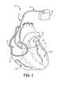
- FIG. 1is a schematic view of a cardiac rhythm management system including a pulse generator coupled to a lead including porous electrodes deployed in a patient's heart.
- FIG. 2is a cross-sectional view of a lead shaft assembly including a single conductor layer according to embodiments of the present invention.
- FIG. 3is a side view of a lead portion including a conductor having a helical pattern, according to an embodiment of the present invention.
- FIG. 4is a side view of a lead portion including a conductor having a helical pattern with alternating winding directions, according to an embodiment of the present invention.
- FIG. 5is a side view of a lead portion including a conductor having a helical pattern with variant winding angles according to an embodiment of the present invention.
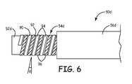
- FIG. 6is a side view of a lead portion including a conductor having multiple filars in a helical pattern, according to an embodiment of the present invention.
- FIGS. 7A-7Eillustrate steps in fabricating a conductor with a helical pattern according to the present invention.
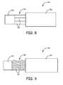
- FIG. 8is a side view of a lead portion including a conductor having a plurality of parallel longitudinally extending straight filars, according to an embodiment of the present invention.
- FIG. 9is a side view of a lead portion including a conductor having a plurality of parallel longitudinally extending undulating filars, according to an embodiment of the present invention.
- FIG. 10is a side view of a lead portion including a conductor having a plurality of parallel longitudinally extending serpentine filars, according to an embodiment of the present invention.
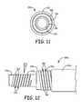
- FIG. 11is a cross-sectional view of a lead shaft assembly including a multiple conductor layers according to embodiments of the present invention.
- FIG. 12is a side view of a lead portion including multiple conductors having a helical pattern, according to an embodiment of the present invention.
- FIG. 13is a side view of a lead portion including multiple solid conductors, according to an embodiment of the present invention.
- FIG. 1is a schematic view of a cardiac rhythm management system 10 including an implantable medical device (IMD) 12 with a lead 14 having a proximal end 16 and a distal end 18 .
- the IMD 12includes a pulse generator such as a pacemaker or a defibrillator.
- the IMD 12can be implanted subcutaneously within the body, typically at a location such as in the patient's chest or abdomen, although other implantation locations are possible.
- the proximal end 16 of the lead 14can be coupled to or formed integrally with the IMD 12 .
- the distal end 18 of the lead 14in turn, can be implanted at a desired location in or near the heart 20 .
- a distal portion of the lead 14is disposed in a patient's heart 20 , which includes a right atrium 22 , a right ventricle 24 , a left atrium 26 , and a left ventricle 28 .
- the distal end 18 of the lead 14is transvenously guided through the right atrium 22 , through the coronary sinus ostium 29 , and into a branch of the coronary sinus 31 or the great cardiac vein 33 .
- the illustrated position of the lead 14can be used for sensing or for delivering pacing and/or defibrillation energy to the left side of the heart 20 , or to treat arrhythmias or other cardiac disorders requiring therapy delivered to the left side of the heart 20 . Additionally, it will be appreciated that the lead 14 can also be used to provide treatment in other regions of the heart 20 (e.g., the right ventricle 24 ).
- the illustrative embodimentdepicts only a single implanted lead 14 , it should be understood that multiple leads can be utilized so as to electrically stimulate other areas of the heart 20 .
- the distal end of a second leadmay be implanted in the right atrium 22
- the distal end of a third leadmay be implanted in the right ventricle 24 .
- Other types of leadssuch as epicardial leads may also be utilized in addition to, or in lieu of, the lead 14 depicted in FIG. 1 .
- the lead 14can be configured to convey electrical signals between the IMD 12 and the heart 20 .
- the lead 14can be utilized to deliver electrical stimuli for pacing the heart 20 .
- the lead 14can be utilized to deliver electric shocks to the heart 20 in response to an event such as a heart attack or arrhythmia.
- the IMD 12includes both pacing and defibrillation capabilities.
- the electrical signalsare carried between the IMD 12 and electrodes at the distal end 18 by one or more conductors extending through the lead 14 .
- the one or more conductorsare electrically coupled to a connector suitable for interfacing with the IMD 12 at the proximal end 16 of the lead 14 , and to one or more electrodes at the distal end 18 .
- the one or more conductorshave a low profile (i.e., the distance from the center to the outer surface of the lead 14 ) to minimize the diameter of the lead 14 .
- the one or more conductorsare configured to impart flexibility to the lead 14 to facilitate traversal of tortuous vascular passages during implantation of the lead 14 .
- the one or more conductorsare configured to minimize effects of magnetic resonance imaging (MRI) scans on the functionality and operation of the lead 14 .
- the one or more conductorsare configured to dissipate electromagnetic energy received by the lead 14 during an MRI scan.
- FIG. 2is a cross-sectional view of a lead shaft assembly 50 , according to an embodiment of the present invention.
- the shaft assembly 50is an exemplary configuration for the body of the lead 14 shown in FIG. 1 .
- the shaft assembly 50includes an inner core layer 52 , an inner conductor 54 , and an outer insulative layer 56 .
- the inner conductor 54is formed on the inner core layer 52
- the outer insulative layer 56is arranged over the inner conductor 54 .
- FIGS. 7A-7EA more detailed description of a process for fabricating the shaft assembly 50 will be described in more detail below with regard to FIGS. 7A-7E .
- the inner core layer 52defines a lumen 58 through the shaft assembly 50 .
- the lumen 58is sized and shaped to receive a guide wire or stylet employed during implantation of the lead 14 .
- the inner core layer 52is comprised of a flexible, non-conductive material.
- the inner core layer 52is comprised of a polymeric material, such as polypropylene, polyamide, polyethylene, or polyurethane.
- the inner conductor 54may include one or more layers of conductive material that are deposited onto the inner core layer 52 .
- the conductive materialmay be deposited using a variety of techniques including, but not limited to, plasma enhanced chemical vapor deposition (PECVD), physical vapor deposition (PVD), or galvanic deposition.
- PECVDplasma enhanced chemical vapor deposition
- PVDphysical vapor deposition
- galvanic depositionThe materials used for the inner conductor 54 may be selected to provide good conductivity as well as good adherence to the inner core layer 52 .
- a thin seed layeris deposited adjacent the inner core layer 52 and a thicker, high conductivity layer is deposited on the seed layer.
- the seed layeris comprised of Ti and the high conductivity layer is comprised of Ag, Al, Au, or Pt.
- the high conductivity layeris comprised of other materials, such as Nb, Ta, or Ti.
- the inner conductor 54has a thickness t c extending between the inner core layer 52 and the outer insulative layer 56 .
- the total thickness t c of the inner conductor 54is in the range of about 0.2 ⁇ m to about 2.0 ⁇ m.
- the thickness t c for the inner conductor 54is less than the thickness of conventional lead conductors, providing for a lead with a lower profile and greater flexibility.
- the cross-section of the inner conductor 54may be fabricated to provide a desired impedance at the lead electrode or electrodes to which the inner conductor 54 is attached.
- the cross-section of the inner conductor 54is such that the impedance of each lead electrode is less than about 80 ⁇ .
- the impedance of each lead electrodemay be in the range of about 20 ⁇ to about 80 ⁇ .
- the outer insulative layer 56is arranged over the inner conductor 54 to isolate the inner conductor 54 from the tissue adjacent to the lead 14 .
- the outer insulative layer 56is made of a flexible, highly durable, fatigue resistant, and bio-compatible insulative material.
- the outer insulative layer 56is comprised of a polymeric material, such as styrene isoprene butadiene (SIBS), polytetrafluoroethylene (PTFE), polyethylene (PE), polypropylene (PP), fluorinated ethylene propylene (FEP), ethylene-tetrafluoroethylene (ETFE), or another biocompatible polymer.
- SIBSstyrene isoprene butadiene
- PTFEpolytetrafluoroethylene
- PEpolyethylene
- PPpolypropylene
- FEPfluorinated ethylene propylene
- ETFEethylene-tetrafluoroethylene
- the outer insulative layer 56is deposited over the inner conductor 54 using processes such as spray coating, dip coating, pulsed laser deposition (PLD), or condensation.
- the outer insulative layer 56may alternatively be formed over the combined inner core layer 52 and inner conductor 54 by pulling the assembly through a tube of insulative material.
- the inner conductor 54is formed with certain characteristics to provide desired physical, electrical, and/or magnetic properties for the lead 14 .
- the conductive material of the inner conductor 54may be patterned to minimize the effects of magnetic resonance imaging (MRI) fields on the performance and response of the lead 14 .
- the inner conductor 54is patterned to have an inductance that prevents the MRI fields from heating the lead electrodes.
- the material or materials for the inner conductor 54may be selected to provide distortion free imaging by minimizing image artifacts and voids around the lead 14 .
- the magnetization induced in a material when placed in a magnetic fieldis a function of the magnetic susceptibility of the material
- conductive materials having a low magnetic susceptibilitye.g., similar to the magnetic susceptibility of water
- the inner conductor 54may also be patterned to provide a desired level of flexibility in the lead 14 , or to provide increased or decreased flexibility in portions of the lead 14 .
- active electrical elementssuch as capacitors and diode AC switches, may be integrated between the conductor paths to avoid coupling of the MRI field into the lead 14 .
- FIGS. 3-6are side views of various embodiments of the shaft assembly 50 shown in FIG. 2 . Portions of the inner conductor 54 and the outer insulative layer 56 are removed to illustrate each of the layers of the shaft assembly 50 .
- the following embodimentsare merely by way of example, and the inner conductor 54 may have any pattern or configuration to provide a lead 14 with desired properties.
- FIG. 3is a side view of a shaft assembly 50 a according to an embodiment of the present invention.
- the shaft assembly 50 aincludes an inner core layer 52 a , an inner conductor 54 a , and an outer insulative layer 56 a .
- the inner core layer 52 a , inner conductor 54 a , and the outer insulative layer 56 amay have properties substantially similar to inner core layer 52 , inner conductor 54 , and outer insulative layer 56 , respectively, as described above with regard to FIG. 2 .
- the inner conductor 54 aincludes a helical pattern.
- the helical patternincludes coil members 60 that are separated by spaces 62 .
- the coil members 60are integral with each other and form a continuous member around the inner core layer 52 a .
- the coil members 60have a winding angle ⁇ with respect to an axis orthogonal to the major axis of the shaft assembly 50 a .
- the winding angle ⁇is in the range of about 1° to about 15°.
- the winding angle ⁇ , as well as the coil-to-coil width of spaces 62 (i.e., pitch length) and the width of coil members 60may be controlled to minimize the effect of MRI fields on the inner conductor 54 a.
- FIG. 4is a side view of a shaft assembly 50 b according to another embodiment of the present invention.
- the shaft assembly 50 bincludes an inner core layer 52 b , an inner conductor 54 b , and an outer insulative layer 56 b .
- the inner core layer 52 b , inner conductor 54 b , and the outer insulative layer 56 bmay have properties substantially similar to inner core layer 52 , inner conductor 54 , and outer insulative layer 56 , respectively, as described above with regard to FIG. 2 .
- the inner conductor 54 bincludes a helical pattern having alternating winding directions.
- the helical patternincludes coil members 70 that are separated by spaces 72 .
- the coil members 70are integral with each other and form a continuous member around the inner core layer 52 b .
- the direction that the coil members 70 are angled with respect to the inner core layer 52 bchanges at coil transition section 74 .
- the coil members 70have a winding angle ⁇ with respect to an axis orthogonal to the major axis of the shaft assembly 50 b .
- the winding angle of the oppositely directed coil members 70is substantially the same as the winding angle ⁇ .
- the winding angle of at least some of the coil members 70may differ from the winding angle ⁇ .
- the winding angle ⁇is in the range of about 1° to about 15°.
- the winding angle ⁇ , as well as the pitch length and the width of coil members 70may be controlled to minimize the effect of MRI fields on the inner conductor 54 b.
- FIG. 5is a side view of a shaft assembly 50 c according to another embodiment of the present invention.
- the shaft assembly 50 cincludes an inner core layer 52 c , an inner conductor 54 c , and an outer insulative layer 56 c .
- the inner core layer 52 c , inner conductor 54 c , and the outer insulative layer 56 cmay have properties substantially similar to inner core layer 52 , inner conductor 54 , and outer insulative layer 56 , respectively, as described above with regard to FIG. 2 .
- the inner conductor 54 cincludes a helical pattern that includes a varying winding angle.
- the helical patternincludes coil members 80 that are separated by spaces 82 .
- the coil members 80are integral with each other and form a continuous member around the inner core layer 52 c .
- the angle at which the coil members 80 are disposed with respect to the inner core layer 52 cchanges at coil transition section 84 .
- the coil members 80have a first winding angle ⁇ 1 with respect to an axis orthogonal to the major axis of the shaft assembly 50 c along a first portion of the shaft assembly 50 c , and a second winding angle ⁇ 2 with respect to an axis orthogonal to the major axis of the shaft assembly 50 c along a second portion of the shaft assembly 50 c .
- the first winding angle ⁇ 1is in the range of about 1° to about 15°
- the second winding angle ⁇ 2is in the range of about 15° to about 60°.
- the winding angles ⁇ 1 and ⁇ 2 , as well as the pitch length and the width of coil members 80may be controlled to minimize the effect of MRI fields on the inner conductor 54 c.
- FIG. 6is a side view of a shaft assembly 50 d according to another embodiment of the present invention.
- the shaft assembly 50 dincludes an inner core layer 52 d , an inner conductor 54 d , and an outer insulative layer 56 d .
- the inner core layer 52 d , inner conductor 54 d , and the outer insulative layer 56 dmay have properties substantially similar to inner core layer 52 , inner conductor 54 , and outer insulative layer 56 , respectively, as described above with regard to FIG. 2 .
- the inner conductor 54 dincludes two co-radial conductive filars 90 and 92 that include a helical pattern.
- the helical pattern of conductive filar 90includes coil members 94
- the conductive filar 92includes coil members 96 .
- the coil members 94are integral with each other and form a continuous member around the inner core layer 52 d .
- the coil members 96are integral with each other and form a continuous member around the inner core layer 52 d .
- the coil members 94 and 96each have a winding angle ⁇ with respect to an axis orthogonal to the major axis of the shaft assembly 50 d .
- the winding angle ⁇is in the range of about 1° to about 15°.
- the winding angle ⁇ as well as the spacing between the filars 90 and 92 and the width of coil members 94 and 96may be controlled to minimize the effect of MRI fields on the inner conductor 54 d.
- FIGS. 7A-7Eillustrate steps in an embodiment of a process for fabricating the shaft assembly 50 .
- the process illustrated in FIGS. 7A-7Emay be employed to fabricate any of the shaft assemblies 50 a - 50 d illustrated in FIGS. 3-6 .
- a first step of the processis shown, wherein a portion of the inner core layer 52 is shown masked with a pattern.
- the inner core layer 52may be masked with a pattern that is related to the desired pattern that the conductive layer 54 will have.
- a fiber 100is wound or spun over the inner core layer 52 .
- the inner core layer 52may be rotated, and the fiber 100 subsequently wrapped around the rotating inner core layer 52 .
- the fiber 100is a metal fiber.
- the fiber 100is wound or spun onto the inner core layer 52 tight enough to impress into the surface 102 of the inner core layer 52 , as is shown in FIG. 7A .
- this stepmay be omitted.
- FIG. 7Bis a side view of a second step of a process for fabricating the shaft assembly 50 , in which the combined inner core layer 52 and fiber 100 is base coated with a base layer 104 .
- the seed layer 104is comprised of a material that adheres well to the material of the inner core layer 52 .
- the materialis conductive and paramagnetic.
- One example material that may be deposited as the base layer 104is titanium.
- the base layer 104has a thickness in the range of about 10 nm to about 30 nm.
- the base layer 104may be deposited onto the shaft assembly 50 using a variety of techniques including, for example, plasma enhanced chemical vapor deposition (PECVD). This technique is described in European Patent No. 0897997, entitled “Composite Material,” which is hereby incorporated by reference in its entirety.
- PECVDplasma enhanced chemical vapor deposition
- FIG. 7Cis a side view of a third step of a process for fabricating the shaft assembly 50 , in which a conductive layer 106 of material is deposited onto the base layer 104 .
- the combined base layer 104 and conductive layer 106form the inner conductor 54 as described above with regard to FIG. 2 .
- the conductive layer 106has a conductivity that is greater than the conductivity of the base layer 104 .
- the conductive layer 106may be diamagnetic.
- Example materials that may be used for the conductive layer 106include, for example, gold or copper.
- the conductive layer 106may have a thickness that is greater than the thickness of the base layer 104 .
- the thickness of the conductive layer 106is in the range of about 0.2 ⁇ m to about 2.0 ⁇ m. For ease of illustration, this substantial difference in thickness is not illustrated in FIG. 7C .
- the use of a larger volume of a diamagnetic material, which has negative magnetic susceptibility, with a very small volume of paramagnetic materialresults in substantially distortion free imaging, with minimal image artifacts or voids around the lead in the magnetic resonance image.
- goldis used for the conductive layer 106 , good x-ray contrasting is provided.
- the conductive layer 106may be deposited onto the base layer 104 in a variety of ways. In some embodiments, the conductive layer 106 is deposited via physical vapor deposition (PVD). In other embodiments, the conductive layer 106 is deposited via galvanic deposition. In further embodiments, the conductive layer 106 is deposited by sputtering, such as laser sputtering. In still further embodiments, the conductive layer 106 is deposited using other techniques suitable for coating the base layer 104 with the conductive layer 106 .
- PVDphysical vapor deposition
- galvanic depositiondeposited by sputtering, such as laser sputtering.
- the conductive layer 106is deposited using other techniques suitable for coating the base layer 104 with the conductive layer 106 .
- FIG. 7Dis a side view of a fourth step of a process for fabricating the shaft assembly 50 , in which the mask (i.e., fiber 100 ) is removed from the inner core layer 52 .
- the maski.e., fiber 100
- the portions of the base layer 104 and the conductive layer 106 that were on the fiber 100are also removed.
- coil members 110remain on the inner core layer 52
- the portions of the assembly from which the fiber 100 was removeddefine spaces 112 between the coil members 110 .
- the spaces 112are indented relative to the outer surface 102 ( FIG. 7A ) due to the tight winding of the fiber 100 .
- the inner core layer 52is exposed in the spaces 112 .
- the fiber 100does not indent the outer surface 102 of the inner core layer 52 .
- FIG. 7Eis a side view of a fifth step of a process for fabricating the shaft assembly 50 , in which the outer insulative layer 56 is arranged over the conductive layer 106 .
- the outer insulative layer 56coats the outside of the shaft assembly 50 and fills the spaces 112 between the coil members 110 with the insulative material to isolate adjacent coil turns from each other.
- the outer insulative layer 56is deposited over the conductive layer 106 using processes such as spray coating, dip coating, pulsed laser deposition (PLD), or condensation.
- PLDpulsed laser deposition
- the outer insulative layer 56may alternatively be formed over the combined inner core layer 52 and inner conductor 54 by pulling the assembly through a tube of insulative material.
- FIG. 8is a side view of a shaft assembly 50 e including an inner core layer 52 e , an inner conductor 54 e , and an outer insulative layer 56 e .
- the inner core layer 52 e , inner conductor 54 e , and the outer insulative layer 56 emay have properties substantially similar to inner core layer 52 , inner conductor 54 , and outer insulative layer 56 , respectively, as described above with regard to FIG. 2 .
- the inner conductor 54 eincludes a plurality of parallel longitudinally extending straight filars 120 .
- the filars 120are connected to the same contact at the IMD 12 to carry a signal between the IMD 12 and the heart 20 .
- each of the filars 120is employed to carry a separate signal between the IMD 12 and the heart 20 .
- FIG. 9is a side view of a shaft assembly 50 f including an inner core layer 52 f , an inner conductor 54 f , and an outer insulative layer 56 f .
- the inner core layer 52 f , inner conductor 54 f , and the outer insulative layer 56 fmay have properties substantially similar to inner core layer 52 , inner conductor 54 , and outer insulative layer 56 , respectively, as described above with regard to FIG. 2 .
- the inner conductor 54 fincludes a plurality of parallel longitudinally extending undulating filars 130 .
- the filars 130are connected to the same contact at the IMD 12 to carry an electrical signal between the IMD 12 and the heart 20 .
- each of the filars 130is employed to carry a separate electrical signal between the IMD 12 and the heart 20 .
- FIG. 10is a side view of a shaft assembly 50 g including an inner core layer 52 g , an inner conductor 54 g , and an outer insulative layer 56 g .
- the inner core layer 52 g , inner conductor 54 g , and the outer insulative layer 56 gmay have properties substantially similar to inner core layer 52 , inner conductor 54 , and outer insulative layer 56 , respectively, as described above with regard to FIG. 2 .
- the inner conductor 54 gincludes a plurality of parallel longitudinally extending serpentine filars 140 .
- the filars 140are connected to the same contact at the IMD 12 to carry an electrical signal between the IMD 12 and the heart 20 .
- each of the filars 140is employed to carry a separate electrical signal between the IMD 12 and the heart 20 .
- FIG. 11is a cross sectional view of a shaft assembly 150 including an inner core layer 152 , a first inner conductor 154 , an intermediate insulative layer 156 , a second inner conductor 158 , and an outer insulative layer 160 .
- the first inner conductor 154is formed on the inner core layer 152
- the intermediate insulative layer 156is formed on the first inner conductor 154
- the second inner conductor 158is formed on the intermediate insulative layer 156
- the outer insulative layer 160is arranged over the inner conductor 158 .
- the inner core layer 152may have properties substantially similar to the inner core layer 52
- the inner conductors 154 and 158may have properties substantially similar to the inner conductor 54
- the intermediate insulative layer 156 and the outer insulative layer 160may have properties substantially similar to the outer insulative layer 56
- the layers of the shaft assembly 150may be formed using techniques substantially similar to those described above with regard to FIGS. 7A-7E .
- FIG. 12is a side view of a shaft assembly 150 a according to an embodiment of the present invention.
- the shaft assembly 150 aincludes an inner core layer 152 a , a first inner conductor 154 a , an intermediate insulative layer 156 a , a second inner conductor 158 a , and an outer insulative layer 160 a .
- the inner conductors 154 a and 158 aeach includes a helical pattern.
- the helical pattern of the first inner conductor 154 aincludes coil members 162 that are separated by spaces 164
- the helical pattern of the second inner conductor 158 aincludes coil members 166 that are separated by spaces 168 .
- the coil members 162 and 166are oppositely oriented with respect to an axis orthogonal to the major axis of the shaft assembly 150 a .
- the coil members 162have a winding angle ⁇ that, in some embodiments, is in the range of about 1° to about 15°.
- the winding angle of the oppositely directed coil members 166 of the second inner conductor 158 ais substantially the same as the winding angle ⁇ . In alternative embodiments, the winding angle of the oppositely directed coil members 166 is different than the winding angle ⁇ .
- FIG. 13is a side view of a shaft assembly 150 b according to an embodiment of the present invention.
- the shaft assembly 150 bincludes an inner core layer 152 b , a first inner conductor 154 b , an intermediate insulative layer 156 b , a second inner conductor 158 b , and an outer insulative layer 160 b .
- the inner conductors 154 a and 158 aare a solid layer of conductive material.
- any number of inner conductorsmay be included in the shaft assembly 150 by patterning additional layers of conductive material on the outside of the shaft assembly, separated by layers of insulative material.
- the inner conductors 154 and 158may be fabricated into any pattern including, for example, those described above in FIGS. 3-6 and FIGS. 8-10 .
- the present inventionrelates to a medical device lead including a thin profile conductor assembly.
- a proximal connectorincludes a proximal end that is configured to couple the lead to a pulse generator.
- An insulative lead bodyextends distally from the proximal connector.
- the conductor assemblyextends distally from the proximal end within the lead body and includes a non-conductive tubular core member that defines a lumen, an outer insulative layer, and a multilayer conductor between the tubular core member and the outer insulative layer.
- the multilayer conductoris electrically connected to the proximal connector and includes a first conductive layer adjacent to the tubular core member and a second conductive layer adjacent to the first conductive layer opposite the tubular core member.
- a conductivity of the second conductive layeris greater than a conductivity of the first conductive layer.
- a medical device lead conductor as describedhas a very low profile, providing leads having small diameters.
- the conductoris configured to impart increased flexibility to the lead to facilitate traversal of tortuous vascular passages during implantation of the lead.
- the conductormay also include features or configurations that make the lead suitable for magnetic resonance imaging (MRI) environments.
- MRImagnetic resonance imaging
Landscapes
- Health & Medical Sciences (AREA)
- Heart & Thoracic Surgery (AREA)
- Vascular Medicine (AREA)
- Cardiology (AREA)
- Engineering & Computer Science (AREA)
- Biomedical Technology (AREA)
- Nuclear Medicine, Radiotherapy & Molecular Imaging (AREA)
- Radiology & Medical Imaging (AREA)
- Life Sciences & Earth Sciences (AREA)
- Animal Behavior & Ethology (AREA)
- General Health & Medical Sciences (AREA)
- Public Health (AREA)
- Veterinary Medicine (AREA)
- Electrotherapy Devices (AREA)
Abstract
Description
This application claims priority to Provisional Application No. 61/159,572, filed Mar. 12, 2009, which is herein incorporated by reference in its entirety.
The present invention relates to implantable medical devices. More particularly, the present invention relates to configurations and methods of manufacture for thin profile conductive assemblies for medical device leads.
Implantable medical devices for treating a variety of medical conditions with electrical stimuli are well known. Implantable medical devices generally include a medical electrical lead for delivering an electrical stimulus to a targeted site within a patient's body such as, for example, a patient's heart or nervous system. Such leads generally have an elongated, flexible insulating body, one or more inner conductors extending through lumens formed in the body and one or more exposed electrodes connected to the distal ends of the conductors.
Leads may be introduced into the patient's vasculature at a venous access site and transvenously guided through veins to the sites where the lead electrodes will be implanted or otherwise contact tissue at the targeted therapy site. A pulse generator attached to the proximal ends of the conductors delivers an electrical stimulus therapy to the targeted site via the one or more conductors.
Discussed herein are various conductor assemblies for implantable medical electrical leads including conductive layers having differing electrical conductivities, as well as medical electrical leads including such conductor assemblies.
In Example 1, a medical device lead includes a proximal connector having a proximal end and configured to couple the lead to a pulse generator, an insulative lead body extending distally from the proximal connector, and a conductor assembly extending distally from the proximal end within the lead body. The conductor assembly includes a non-conductive tubular core member that defines a lumen, an outer insulative layer, and a multilayer conductor between the tubular core member and the outer insulative layer. The multilayer conductor is electrically connected to the proximal connector and includes a first conductive layer adjacent the tubular core member and a second conductive layer adjacent the first conductive layer opposite the tubular core member. A conductivity of the second conductive layer is greater than a conductivity of the first conductive layer.
In Example 2, the medical device lead according to Example 1, wherein a thickness of the first conductive layer in a dimension extending between the tubular core member and the outer insulative layer is less than a thickness of the second conductive layer.
In Example 3, the medical device lead according to either Example 1 or 2, wherein the thickness of the first conductive layer is in the range of about 10 to about 30 nm and the thickness of the second conductive layer is in the range of about 0.2 to about 2 μm.
In Example 4, the medical device lead according to any of Examples 1-3, wherein the first conductive layer is comprised of a paramagnetic material and the second conductive layer is comprised of a diamagnetic material.
In Example 5, the medical device lead according to any of Examples 1-4, wherein the first conductive layer is comprised of Ti, and the second conductive layer is comprised of a material selected from the group consisting of Ag, Al, Au, and Pt.
According to Example 6, a method for making a conductive assembly for a medical electrical lead includes masking a non-conductive tubular core member with a pattern. The tubular core member defines a lumen. The method also includes depositing a first conductive layer on the masked tubular core member, and depositing a second conductive layer on the first conductive layer. The second conductive layer has a conductivity greater than the first conductive layer. The method further includes removing the mask from the tubular core member such that portions of the first conductive layer and the second conductive layer deposited on the mask are removed with the mask and a first conductive pattern remains on the tubular core member. The method further includes covering the tubular core member and the first conductive pattern with a first insulative layer.
In Example 7, the method according to Example 6, wherein masking the tubular core member with the pattern comprises spinning a fibrous material over the tubular core member.
In Example 8, the method according to either Example 6 or 7, wherein the first conductive layer is deposited on the masked tube via plasma enhanced chemical vapor deposition (PECVD).
In Example 9, the method according to any of Examples 6-8, wherein the second conductive layer is deposited on the first conductive layer via physical vapor deposition (PVD).
In Example 10, the method according to any of Examples 6-9, wherein the second conductive layer is deposited on the first conductive layer via galvanic deposition.
In Example 11, the method according to any of Examples 6-10, wherein a thickness of the first conductive layer in a dimension extending between the tubular core member and the outer insulative layer is less than a thickness of the second conductive layer.
In Example 12, the method according to any of Examples 6-11, wherein the first conductive layer is comprised of a paramagnetic material and the second conductive layer is comprised of a diamagnetic material.
In Example 13, the method according to any of Examples 6-12, wherein the tubular core member is covered with the first insulative layer via any of spray coating, dip coating, pulsed laser deposition, or condensation.
In Example 14, the method according to any of Examples 6-13, wherein the tubular core member and the first insulative layer are comprised of a polymer.
In Example 15, the method according to any of Examples 6-14, and further comprising (a) masking the first insulative layer with a pattern, (b) depositing a third conductive layer on the masked first insulative layer, (c) depositing a fourth conductive layer on the third conductive layer, wherein the fourth conductive layer has a conductivity greater than the third conductive layer, (d) removing the mask from the first insulative layer such that portions of the third conductive layer and the fourth conductive layer deposited on the mask are removed with the mask and a second conductive pattern remains on the first insulative layer, and (e) covering the first insulative layer and the second conductive pattern with a second insulative layer.
According to Example 16, a conductor assembly for a medical device lead includes a non-conductive tubular core member having a lumen, and an outer insulative layer is disposed about the non-conductive tubular core member. A multilayer conductor is between the tubular core member and the outer insulative layer. The multilayer conductor defines a conductor pattern and includes a first conductive layer adjacent to the tubular core member and a second conductive layer adjacent to the first conductive layer opposite the tubular core member. A conductivity of the second conductive layer is greater than a conductivity of the first conductive layer.
In Example 17, the conductor assembly according to Example 16, wherein a thickness of the first conductive layer in a dimension extending between the tubular core member and the outer insulative layer is less than a thickness of the second conductive layer.
In Example 18, the conductor assembly according to either Example 16 or 17, wherein the thickness of the first conductive layer is in the range of about 10 to about 30 nm and the thickness of the second conductive layer is in the range of about 0.2 to about 2 μm.
In Example 19, the conductor assembly according to any of Examples 16-18, wherein the first conductive layer is comprised of a paramagnetic material and the second conductive layer is comprised of a diamagnetic material.
In Example 20, the conductor assembly according to any of Examples 16-19, wherein the conductor pattern is helical.
In Example 21, the conductor assembly according to any of Examples 16-20, wherein turns of the helical pattern have a varying pitch along a major dimension of the conductor assembly.
In Example 22, the conductor assembly according to any of Examples 16-21, wherein the conductor pattern comprises a plurality of longitudinally extending conductive filars.
In Example 23, the conductor assembly according to any of Examples 16-22, wherein each of the longitudinally extending conductive filars is substantially straight.
In Example 24, the conductor assembly according to any of Examples 16-23, wherein each of the longitudinally extending conductive filars is undulating.
In Example 25, the conductor assembly according to any of Examples 16-24, wherein each of the longitudinally extending conductive filars is serpentine.
In Example 26, the conductor assembly according to any of Examples 16-25, wherein the multilayer conductor defines more than one conductive path.
While multiple embodiments are disclosed, still other embodiments of the present invention will become apparent to those skilled in the art from the following detailed description, which shows and describes illustrative embodiments of the invention. Accordingly, the drawings and detailed description are to be regarded as illustrative in nature and not restrictive.
While the invention is amenable to various modifications and alternative forms, specific embodiments have been shown by way of example in the drawings and are described in detail below. The intention, however, is not to limit the invention to the particular embodiments described. On the contrary, the invention is intended to cover all modifications, equivalents, and alternatives falling within the scope of the invention as defined by the appended claims.
As shown inFIG. 1 , a distal portion of thelead 14 is disposed in a patient'sheart 20, which includes aright atrium 22, aright ventricle 24, aleft atrium 26, and aleft ventricle 28. In the embodiment illustrated inFIG. 1 , thedistal end 18 of thelead 14 is transvenously guided through theright atrium 22, through thecoronary sinus ostium 29, and into a branch of thecoronary sinus 31 or the great cardiac vein33. The illustrated position of thelead 14 can be used for sensing or for delivering pacing and/or defibrillation energy to the left side of theheart 20, or to treat arrhythmias or other cardiac disorders requiring therapy delivered to the left side of theheart 20. Additionally, it will be appreciated that thelead 14 can also be used to provide treatment in other regions of the heart20 (e.g., the right ventricle24).
Although the illustrative embodiment depicts only a single implantedlead 14, it should be understood that multiple leads can be utilized so as to electrically stimulate other areas of theheart 20. In some embodiments, for example, the distal end of a second lead (not shown) may be implanted in theright atrium 22, and/or the distal end of a third lead (not shown) may be implanted in theright ventricle 24. Other types of leads such as epicardial leads may also be utilized in addition to, or in lieu of, thelead 14 depicted inFIG. 1 .
During operation, thelead 14 can be configured to convey electrical signals between theIMD 12 and theheart 20. For example, in those embodiments where theIMD 12 is a pacemaker, thelead 14 can be utilized to deliver electrical stimuli for pacing theheart 20. In those embodiments where theIMD 12 is an implantable cardiac defibrillator, thelead 14 can be utilized to deliver electric shocks to theheart 20 in response to an event such as a heart attack or arrhythmia. In some embodiments, theIMD 12 includes both pacing and defibrillation capabilities.
The electrical signals are carried between theIMD 12 and electrodes at thedistal end 18 by one or more conductors extending through thelead 14. The one or more conductors are electrically coupled to a connector suitable for interfacing with theIMD 12 at theproximal end 16 of thelead 14, and to one or more electrodes at thedistal end 18. According to the present invention, the one or more conductors have a low profile (i.e., the distance from the center to the outer surface of the lead14) to minimize the diameter of thelead 14. In addition, the one or more conductors are configured to impart flexibility to thelead 14 to facilitate traversal of tortuous vascular passages during implantation of thelead 14. Also, in some embodiments, the one or more conductors are configured to minimize effects of magnetic resonance imaging (MRI) scans on the functionality and operation of thelead 14. For example, in certain embodiments, the one or more conductors are configured to dissipate electromagnetic energy received by thelead 14 during an MRI scan.
Theinner core layer 52 defines alumen 58 through theshaft assembly 50. In some embodiments, thelumen 58 is sized and shaped to receive a guide wire or stylet employed during implantation of thelead 14. Theinner core layer 52 is comprised of a flexible, non-conductive material. In some embodiments, theinner core layer 52 is comprised of a polymeric material, such as polypropylene, polyamide, polyethylene, or polyurethane.
Theinner conductor 54 may include one or more layers of conductive material that are deposited onto theinner core layer 52. The conductive material may be deposited using a variety of techniques including, but not limited to, plasma enhanced chemical vapor deposition (PECVD), physical vapor deposition (PVD), or galvanic deposition. The materials used for theinner conductor 54 may be selected to provide good conductivity as well as good adherence to theinner core layer 52. In some embodiments, a thin seed layer is deposited adjacent theinner core layer 52 and a thicker, high conductivity layer is deposited on the seed layer. In some embodiments, the seed layer is comprised of Ti and the high conductivity layer is comprised of Ag, Al, Au, or Pt. In other embodiments, the high conductivity layer is comprised of other materials, such as Nb, Ta, or Ti. Theinner conductor 54 has a thickness tcextending between theinner core layer 52 and theouter insulative layer 56. In some embodiments, the total thickness tcof theinner conductor 54 is in the range of about 0.2 μm to about 2.0 μm. The thickness tcfor theinner conductor 54 is less than the thickness of conventional lead conductors, providing for a lead with a lower profile and greater flexibility.
The cross-section of theinner conductor 54 may be fabricated to provide a desired impedance at the lead electrode or electrodes to which theinner conductor 54 is attached. In some embodiments, the cross-section of theinner conductor 54 is such that the impedance of each lead electrode is less than about 80Ω. For example, the impedance of each lead electrode may be in the range of about 20Ω to about 80Ω.
Theouter insulative layer 56 is arranged over theinner conductor 54 to isolate theinner conductor 54 from the tissue adjacent to thelead 14. Theouter insulative layer 56 is made of a flexible, highly durable, fatigue resistant, and bio-compatible insulative material. In some embodiments, theouter insulative layer 56 is comprised of a polymeric material, such as styrene isoprene butadiene (SIBS), polytetrafluoroethylene (PTFE), polyethylene (PE), polypropylene (PP), fluorinated ethylene propylene (FEP), ethylene-tetrafluoroethylene (ETFE), or another biocompatible polymer. In some embodiments, theouter insulative layer 56 is deposited over theinner conductor 54 using processes such as spray coating, dip coating, pulsed laser deposition (PLD), or condensation. Theouter insulative layer 56 may alternatively be formed over the combinedinner core layer 52 andinner conductor 54 by pulling the assembly through a tube of insulative material.
According to some embodiments, theinner conductor 54 is formed with certain characteristics to provide desired physical, electrical, and/or magnetic properties for thelead 14. For example, the conductive material of theinner conductor 54 may be patterned to minimize the effects of magnetic resonance imaging (MRI) fields on the performance and response of thelead 14. In some embodiments, theinner conductor 54 is patterned to have an inductance that prevents the MRI fields from heating the lead electrodes. In addition, the material or materials for theinner conductor 54 may be selected to provide distortion free imaging by minimizing image artifacts and voids around thelead 14. For example because the magnetization induced in a material when placed in a magnetic field is a function of the magnetic susceptibility of the material, conductive materials having a low magnetic susceptibility (e.g., similar to the magnetic susceptibility of water) may be used. Theinner conductor 54 may also be patterned to provide a desired level of flexibility in thelead 14, or to provide increased or decreased flexibility in portions of thelead 14. Furthermore, in embodiments with multiple inner conductors, active electrical elements, such as capacitors and diode AC switches, may be integrated between the conductor paths to avoid coupling of the MRI field into thelead 14.
Theconductive layer 106 may be deposited onto thebase layer 104 in a variety of ways. In some embodiments, theconductive layer 106 is deposited via physical vapor deposition (PVD). In other embodiments, theconductive layer 106 is deposited via galvanic deposition. In further embodiments, theconductive layer 106 is deposited by sputtering, such as laser sputtering. In still further embodiments, theconductive layer 106 is deposited using other techniques suitable for coating thebase layer 104 with theconductive layer 106.
It will be appreciated that the configuration for theinner conductor 54 is not limited to the helical pattern shown, and that the principles of the present invention may be applied toinner conductors 54 having other types of patterns. For example,FIG. 8 is a side view of ashaft assembly 50eincluding aninner core layer 52e, aninner conductor 54e, and anouter insulative layer 56e. Theinner core layer 52e,inner conductor 54e, and theouter insulative layer 56emay have properties substantially similar toinner core layer 52,inner conductor 54, andouter insulative layer 56, respectively, as described above with regard toFIG. 2 . In the embodiment shown inFIG. 8 , theinner conductor 54eincludes a plurality of parallel longitudinally extendingstraight filars 120. In some embodiments, thefilars 120 are connected to the same contact at theIMD 12 to carry a signal between theIMD 12 and theheart 20. In other embodiments, each of thefilars 120 is employed to carry a separate signal between theIMD 12 and theheart 20.
In certain applications, the lead14 (FIG. 1 ) may include multiple co-axial conductors to carry signals having different purposes or electrical characteristics between theIMD 12 and theheart 20. For example,FIG. 11 is a cross sectional view of ashaft assembly 150 including aninner core layer 152, a firstinner conductor 154, anintermediate insulative layer 156, a secondinner conductor 158, and anouter insulative layer 160. The firstinner conductor 154 is formed on theinner core layer 152, theintermediate insulative layer 156 is formed on the firstinner conductor 154, the secondinner conductor 158 is formed on theintermediate insulative layer 156, and theouter insulative layer 160 is arranged over theinner conductor 158. Theinner core layer 152 may have properties substantially similar to theinner core layer 52, theinner conductors inner conductor 54, and theintermediate insulative layer 156 and theouter insulative layer 160 may have properties substantially similar to theouter insulative layer 56. In addition, the layers of theshaft assembly 150 may be formed using techniques substantially similar to those described above with regard toFIGS. 7A-7E .
It will be appreciated that while twoinner conductors FIGS. 12 and 13 , any number of inner conductors may be included in theshaft assembly 150 by patterning additional layers of conductive material on the outside of the shaft assembly, separated by layers of insulative material. In addition, it will be appreciated that theinner conductors FIGS. 3-6 andFIGS. 8-10 .
In summary, the present invention relates to a medical device lead including a thin profile conductor assembly. A proximal connector includes a proximal end that is configured to couple the lead to a pulse generator. An insulative lead body extends distally from the proximal connector. The conductor assembly extends distally from the proximal end within the lead body and includes a non-conductive tubular core member that defines a lumen, an outer insulative layer, and a multilayer conductor between the tubular core member and the outer insulative layer. The multilayer conductor is electrically connected to the proximal connector and includes a first conductive layer adjacent to the tubular core member and a second conductive layer adjacent to the first conductive layer opposite the tubular core member. A conductivity of the second conductive layer is greater than a conductivity of the first conductive layer. A medical device lead conductor as described has a very low profile, providing leads having small diameters. In addition, the conductor is configured to impart increased flexibility to the lead to facilitate traversal of tortuous vascular passages during implantation of the lead. The conductor may also include features or configurations that make the lead suitable for magnetic resonance imaging (MRI) environments.
Various modifications and additions can be made to the exemplary embodiments discussed without departing from the scope of the present invention. While the embodiments described above refer to particular features, the scope of this invention also includes embodiments having different combinations of features and embodiments that do not include all of the described features. Accordingly, the scope of the present invention is intended to embrace all such alternatives, modifications, and variations as fall within the scope of the claims, together with all equivalents thereof. For example, while the deposited conductive material has been described with regard to the inner conductor(s) of a cardiac lead it will be appreciated that the principles of the present invention are applicable to other types of leads, such as neuromodulation leads, as well as other types of conductive coating applications, such as housings, flexible electrodes, and electromagnetic interference (EMI) shielding.
Claims (21)
1. A method for making a conductive assembly for a medical electrical lead, the method comprising:
masking a non-conductive tubular core member by winding a mask helically around the non-conductive tubular core member to form gaps between adjacent turns of the mask, wherein the tubular core member defines a lumen;
depositing a first conductive layer on the masked tubular core member, the first conductive layer deposited on the non-conductive tubular core member in the gaps between adjacent turns of the mask;
depositing a second conductive layer on the first conductive layer, wherein the second conductive layer has a conductivity greater than the first conductive layer;
removing the mask from the tubular core member such that portions of the first conductive layer and the second conductive layer deposited on the mask are removed with the mask and a helical conductive pattern remains on the tubular core member, the helical conductive pattern comprising the first conductive layer and the second conductive layer; and
covering the tubular core member and the helical conductive pattern with a first insulative layer.
2. The method ofclaim 1 , wherein masking the tubular core member comprises spinning a fibrous material over the tubular core member.
3. The method ofclaim 1 , wherein the first conductive layer is deposited on the masked tube via plasma enhanced chemical vapor deposition (PECVD).
4. The method ofclaim 1 , wherein the second conductive layer is deposited on the first conductive layer via physical vapor deposition (PVD).
5. The method ofclaim 1 , wherein the second conductive layer is deposited on the first conductive layer via galvanic deposition.
6. The method ofclaim 1 , wherein a thickness of the first conductive layer in a dimension extending between the tubular core member and the outer insulative layer is less than a thickness of the second conductive layer.
7. The method ofclaim 1 , wherein the first conductive layer is comprised of a paramagnetic material and the second conductive layer is comprised of a diamagnetic material.
8. The method ofclaim 1 , wherein the tubular core member is covered with the first insulative layer via any of spray coating, dip coating, pulsed laser deposition, or condensation.
9. The method ofclaim 1 , wherein the tubular core member and the first insulative layer are comprised of a polymer.
10. The method ofclaim 1 , and further comprising:
masking the first insulative layer with a pattern;
depositing a third conductive layer on the masked first insulative layer;
depositing a fourth conductive layer on the third conductive layer, wherein the fourth conductive layer has a conductivity greater than the third conductive layer;
removing the mask from the first insulative layer such that portions of the third conductive layer and the fourth conductive layer deposited on the mask are removed with the mask and a second conductive pattern remains on the first insulative layer; and
covering the first insulative layer and the second conductive pattern with a second insulative layer.
11. The method ofclaim 1 , wherein masking the non-conductive tubular core member further comprises indenting the non-conductive tubular core member with the mask as the mask is helically wound around the non-conductive tubular core member.
12. The method ofclaim 1 , wherein removal of the mask from around the tubular core member exposes spaces of the non-conductive tubular core member between adjacent turns of the helical conductor pattern.
13. The method ofclaim 12 , wherein covering the tubular core member with the first insulative layer comprises filling the spaces between adjacent turns of the helical conductor pattern with material of the first insulative layer.
14. A method for making a conductive assembly for a medical electrical lead, the method comprising:
masking a non-conductive tubular core member by winding a mask helically around the non-conductive tubular core member to form gaps between adjacent turns of the mask;
depositing a conductive layer on the mask and on the non-conductive tubular core member in the gaps between adjacent turns of the mask;
removing the mask from the tubular core member such that portions of the conductive layer deposited on the mask are removed with the mask while a helical conductive pattern remains on the tubular core member, the helical conductive pattern comprising the conductive layer; and
covering the tubular core member and the helical conductive pattern with a insulative layer.
15. The method ofclaim 14 , wherein masking the tubular core member comprises spinning a fibrous material over the tubular core member.
16. The method ofclaim 14 , wherein the conductive layer is deposited on the masked tube via plasma enhanced chemical vapor deposition (PECVD).
17. The method ofclaim 14 , wherein the tubular core member is covered with the insulative layer via any of spray coating, dip coating, pulsed laser deposition, or condensation.
18. The method ofclaim 14 , wherein the tubular core member and the insulative layer are comprised of a polymer.
19. The method ofclaim 14 , wherein masking the non-conductive tubular core member further comprises indenting the non-conductive tubular core member with the mask as the mask is helically wound around the non-conductive tubular core member.
20. The method ofclaim 14 , wherein removal of the mask from around the tubular core member exposes spaces of the non-conductive tubular core member between adjacent turns of the helical conductor pattern.
21. The method ofclaim 20 , wherein covering the tubular core member with the insulative layer comprises filling the spaces between adjacent turns of the helical conductor pattern with material of the insulative layer.
Priority Applications (1)
| Application Number | Priority Date | Filing Date | Title |
|---|---|---|---|
| US12/704,939US9084883B2 (en) | 2009-03-12 | 2010-02-12 | Thin profile conductor assembly for medical device leads |
Applications Claiming Priority (2)
| Application Number | Priority Date | Filing Date | Title |
|---|---|---|---|
| US15957209P | 2009-03-12 | 2009-03-12 | |
| US12/704,939US9084883B2 (en) | 2009-03-12 | 2010-02-12 | Thin profile conductor assembly for medical device leads |
Publications (2)
| Publication Number | Publication Date |
|---|---|
| US20100234929A1 US20100234929A1 (en) | 2010-09-16 |
| US9084883B2true US9084883B2 (en) | 2015-07-21 |
Family
ID=42101666
Family Applications (1)
| Application Number | Title | Priority Date | Filing Date |
|---|---|---|---|
| US12/704,939Active2034-01-11US9084883B2 (en) | 2009-03-12 | 2010-02-12 | Thin profile conductor assembly for medical device leads |
Country Status (2)
| Country | Link |
|---|---|
| US (1) | US9084883B2 (en) |
| WO (1) | WO2010104643A2 (en) |
Cited By (1)
| Publication number | Priority date | Publication date | Assignee | Title |
|---|---|---|---|---|
| US20180061524A1 (en)* | 2011-10-06 | 2018-03-01 | 3Dt Holdings, Llc | Devices and systems for obtaining conductance data and methods of manufacturing and using the same |
Families Citing this family (29)
| Publication number | Priority date | Publication date | Assignee | Title |
|---|---|---|---|---|
| US7610101B2 (en)* | 2006-11-30 | 2009-10-27 | Cardiac Pacemakers, Inc. | RF rejecting lead |
| AU2008335462B2 (en) | 2007-12-06 | 2014-02-20 | Cardiac Pacemakers, Inc. | Implantable lead having a variable coil conductor pitch |
| WO2009100003A1 (en) | 2008-02-06 | 2009-08-13 | Cardiac Pacemakers, Inc. | Lead with mri compatible design features |
| US8103360B2 (en) | 2008-05-09 | 2012-01-24 | Foster Arthur J | Medical lead coil conductor with spacer element |
| US8850702B2 (en)* | 2009-05-26 | 2014-10-07 | Cardiac Pacemakers, Inc. | Cable consolidation with a laser |
| ES2547713T3 (en)* | 2009-06-26 | 2015-10-08 | Cardiac Pacemakers, Inc. | Bypass of a medical device that includes a single-coil coil with improved torque transmission capacity and reduced RM heating |
| US8335572B2 (en) | 2009-10-08 | 2012-12-18 | Cardiac Pacemakers, Inc. | Medical device lead including a flared conductive coil |
| US9254380B2 (en) | 2009-10-19 | 2016-02-09 | Cardiac Pacemakers, Inc. | MRI compatible tachycardia lead |
| US20110288388A1 (en)* | 2009-11-20 | 2011-11-24 | Medtronic Minimed, Inc. | Multi-conductor lead configurations useful with medical device systems and methods for making and using them |
| US9750944B2 (en) | 2009-12-30 | 2017-09-05 | Cardiac Pacemakers, Inc. | MRI-conditionally safe medical device lead |
| WO2011081713A1 (en) | 2009-12-31 | 2011-07-07 | Cardiac Pacemakers, Inc. | Mri conditionally safe lead with multi-layer conductor |
| US8391994B2 (en) | 2009-12-31 | 2013-03-05 | Cardiac Pacemakers, Inc. | MRI conditionally safe lead with low-profile multi-layer conductor for longitudinal expansion |
| US20110202104A1 (en)* | 2010-02-17 | 2011-08-18 | Pacesetter, Inc. | Method and system for automatically switching between modes of an implantable medical device based on an external magnetic field |
| US8825181B2 (en) | 2010-08-30 | 2014-09-02 | Cardiac Pacemakers, Inc. | Lead conductor with pitch and torque control for MRI conditionally safe use |
| US20120101558A1 (en)* | 2010-10-26 | 2012-04-26 | Pacesetter, Inc. | Implantable leads having coiled conductors to reduce rf-induced current |
| US20120253445A1 (en)* | 2011-03-31 | 2012-10-04 | Oscor Inc. | MRI compatible conductor system for catheter and stimulation leads |
| US8666512B2 (en) | 2011-11-04 | 2014-03-04 | Cardiac Pacemakers, Inc. | Implantable medical device lead including inner coil reverse-wound relative to shocking coil |
| AU2013249088B2 (en) | 2012-04-20 | 2015-12-03 | Cardiac Pacemakers, Inc. | Implantable medical device lead including a unifilar coiled cable |
| US8954168B2 (en) | 2012-06-01 | 2015-02-10 | Cardiac Pacemakers, Inc. | Implantable device lead including a distal electrode assembly with a coiled component |
| EP2890414B1 (en)* | 2012-08-29 | 2019-01-16 | Cardiac Pacemakers, Inc. | Enhanced low friction coating for medical leads and methods of making |
| JP6069499B2 (en) | 2012-08-31 | 2017-02-01 | カーディアック ペースメイカーズ, インコーポレイテッド | Lead wire with low peak MRI heating |
| US8983623B2 (en) | 2012-10-18 | 2015-03-17 | Cardiac Pacemakers, Inc. | Inductive element for providing MRI compatibility in an implantable medical device lead |
| WO2014074876A1 (en)* | 2012-11-09 | 2014-05-15 | Cardiac Pacemakers, Inc. | Implantable lead having a lumen with a wear-resistant liner |
| US9119956B2 (en) | 2012-11-21 | 2015-09-01 | Cardiac Pacemakers, Inc. | Medical electrodes with layered coatings |
| WO2015130753A1 (en) | 2014-02-26 | 2015-09-03 | Cardiac Pacemakers, Inc | Construction of an mri-safe tachycardia lead |
| US10335590B2 (en)* | 2014-09-10 | 2019-07-02 | The General Hospital Corporation | MRI compatible leads for a deep brain stimulation system |
| EP3442651B1 (en)* | 2016-04-15 | 2022-04-13 | Medtronic, Inc. | Medical device lead assembly with variable pitch coil |
| US11439810B2 (en)* | 2017-07-18 | 2022-09-13 | Regents Of The University Of Minnesota | Tunable neural electrode |
| WO2021062480A1 (en)* | 2019-10-04 | 2021-04-08 | Saluda Medical Pty Limited | Lead for an active implantable medical device |
Citations (305)
| Publication number | Priority date | Publication date | Assignee | Title |
|---|---|---|---|---|
| US2405449A (en)* | 1943-12-31 | 1946-08-06 | Sprague Electric Co | Electrical resistance element |
| US3614692A (en) | 1970-06-02 | 1971-10-19 | Magnetech Ind Inc | Variable induction device |
| US4131759A (en) | 1977-08-10 | 1978-12-26 | United States Steel Corporation | Slip sleeve mechanism for a strength tapered caged armored electromechanical cable |
| US4135518A (en) | 1976-05-21 | 1979-01-23 | Medtronic, Inc. | Body implantable lead and electrode |
| US4146036A (en) | 1977-10-06 | 1979-03-27 | Medtronic, Inc. | Body-implantable lead with protector for tissue securing means |
| US4209019A (en) | 1979-01-05 | 1980-06-24 | Medtronic, Inc. | Stylet insertion guide and rotation control device for use with body implantable lead |
| US4253462A (en) | 1979-08-09 | 1981-03-03 | Medtronic, Inc. | Stylet |
| US4350169A (en) | 1979-01-05 | 1982-09-21 | Medtronic, Inc. | Flexible tip stiffening stylet for use with body implantable lead |
| US4381013A (en) | 1981-03-19 | 1983-04-26 | Medtronic, Inc. | "J" Stylet wire |
| US4404125A (en) | 1981-10-14 | 1983-09-13 | General Electric Company | Polyphenylene ether resin compositions for EMI electromagnetic interference shielding |
| US4437474A (en) | 1982-07-16 | 1984-03-20 | Cordis Corporation | Method for making multiconductor coil and the coil made thereby |
| US4484586A (en) | 1982-05-27 | 1984-11-27 | Berkley & Company, Inc. | Hollow conductive medical tubing |
| US4493329A (en) | 1982-08-19 | 1985-01-15 | Lynn Crawford | Implantable electrode having different stiffening and curvature maintaining characteristics along its length |
| US4574800A (en) | 1984-12-07 | 1986-03-11 | Cordis Corporation | Implanted lead extractor |
| US4643202A (en) | 1985-04-15 | 1987-02-17 | Cordis Corporation | Multi-material insulation sheath for pacer lead |
| US4649938A (en) | 1985-04-29 | 1987-03-17 | Mcarthur William A | Tissue-stimulating electrode having sealed, low-friction extendable/retractable active fixation means |
| US4869970A (en) | 1986-07-14 | 1989-09-26 | Shipley Company Inc. | Radiation attenuation shielding |
| US5002067A (en) | 1989-08-23 | 1991-03-26 | Medtronic, Inc. | Medical electrical lead employing improved penetrating electrode |
| US5003975A (en) | 1988-04-19 | 1991-04-02 | Siemens-Pacesetter, Inc. | Automatic electrode configuration of an implantable pacemaker |
| US5020545A (en) | 1990-01-23 | 1991-06-04 | Siemens-Pacesetter, Inc. | Cardiac lead assembly and method of attaching a cardiac lead assembly |
| US5056516A (en) | 1989-11-02 | 1991-10-15 | Intermedics, Inc. | Implantable endocordial lead with torque-transmitting lanyard |
| US5074313A (en) | 1989-03-20 | 1991-12-24 | Cardiac Pacemakers, Inc. | Porous electrode with enhanced reactive surface |
| US5144960A (en) | 1991-03-20 | 1992-09-08 | Medtronic, Inc. | Transvenous defibrillation lead and method of use |
| US5201865A (en) | 1991-10-28 | 1993-04-13 | Medtronic, Inc. | Medical lead impedance measurement system |
| US5217010A (en) | 1991-05-28 | 1993-06-08 | The Johns Hopkins University | Ecg amplifier and cardiac pacemaker for use during magnetic resonance imaging |
| US5222506A (en) | 1991-07-29 | 1993-06-29 | Medtronic, Inc. | Implantable medical lead with electrical cross-over adaptor |
| US5231996A (en) | 1992-01-28 | 1993-08-03 | Medtronic, Inc. | Removable endocardial lead |
| US5241957A (en) | 1991-11-18 | 1993-09-07 | Medtronic, Inc. | Bipolar temporary pacing lead and connector and permanent bipolar nerve wire |
| US5243911A (en) | 1990-09-18 | 1993-09-14 | Dow Robert L | Attenuator for protecting electronic equipment from undesired exposure to RF energy and/or lightning |
| US5246014A (en) | 1991-11-08 | 1993-09-21 | Medtronic, Inc. | Implantable lead system |
| US5259395A (en) | 1992-01-15 | 1993-11-09 | Siemens Pacesetter, Inc. | Pacemaker lead with extendable retractable lockable fixing helix |
| US5300108A (en) | 1993-01-05 | 1994-04-05 | Telectronics Pacing Systems, Inc. | Active fixation lead with a dual-pitch, free spinning compound screw |
| US5324322A (en)* | 1992-04-20 | 1994-06-28 | Case Western Reserve University | Thin film implantable electrode and method of manufacture |
| US5330522A (en) | 1992-12-29 | 1994-07-19 | Siemens Pacesetter, Inc. | Ring electrode for a multilumen lead and method of constructing a multilumen lead |
| US5354327A (en) | 1993-04-07 | 1994-10-11 | Medtronic, Inc. | Conductor coil with specific ratio of torque to bending stiffness |
| US5370666A (en) | 1992-06-05 | 1994-12-06 | Siemens-Elema Ab | Pacemaker with power-consuming component inhibited during storage |
| US5378234A (en) | 1993-03-15 | 1995-01-03 | Pilot Cardiovascular Systems, Inc. | Coil polymer composite |
| US5387199A (en) | 1992-02-24 | 1995-02-07 | Baxter International Inc. | Polymer blends for torque transmitting catheters |
| US5417208A (en)* | 1993-10-12 | 1995-05-23 | Arrow International Investment Corp. | Electrode-carrying catheter and method of making same |
| US5425755A (en) | 1992-12-04 | 1995-06-20 | Pacesetter, Inc. | Rotatable pin, screw-in pacing and sensing lead having Teflon-coated conductor coil |
| US5456707A (en) | 1993-10-22 | 1995-10-10 | Vitatron Medical Bv | Pacing lead with improved torsion characteristics |
| US5476485A (en) | 1993-09-21 | 1995-12-19 | Pacesetter, Inc. | Automatic implantable pulse generator |
| US5483022A (en) | 1994-04-12 | 1996-01-09 | Ventritex, Inc. | Implantable conductor coil formed from cabled composite wire |
| WO1996006655A1 (en) | 1994-08-29 | 1996-03-07 | Angeion Corporation | Low profile defibrillation catheter |
| US5522875A (en) | 1994-07-28 | 1996-06-04 | Medtronic, Inc. | Medical electrical lead system having a torque transfer stylet |
| US5522872A (en) | 1994-12-07 | 1996-06-04 | Ventritex, Inc. | Electrode-conductor sleeve joint for cardiac lead |
| US5534018A (en) | 1994-11-30 | 1996-07-09 | Medtronic, Inc. | Automatic lead recognition for implantable medical device |
| US5542173A (en) | 1993-09-24 | 1996-08-06 | Ventritex, Inc. | Method of making flexible defibrillation electrode |
| US5545205A (en) | 1989-12-08 | 1996-08-13 | Cardiac Pacemakers, Inc. | Unitary intravascular defibrillating catheter with bipolar sensing |
| US5549646A (en) | 1994-12-06 | 1996-08-27 | Pacesetter, Inc. | Periodic electrical lead intergrity testing system and method for implantable cardiac stimulating devices |
| US5554139A (en) | 1993-12-24 | 1996-09-10 | Terumo Kabushiki Kaisha | Catheter |
| US5574249A (en) | 1994-07-18 | 1996-11-12 | Lindsay Audiophile Inc. | High resistivity inner shields for cabinets housing electronic circuitry |
| US5584873A (en) | 1995-05-08 | 1996-12-17 | Medtronic, Inc. | Medical lead with compression lumens |
| US5599576A (en) | 1995-02-06 | 1997-02-04 | Surface Solutions Laboratories, Inc. | Medical apparatus with scratch-resistant coating and method of making same |
| US5609622A (en) | 1993-02-01 | 1997-03-11 | W. L. Gore & Associates, Inc. | Implantable electrode with conductive polytetrafluoroethylene elecrode |
| US5618208A (en) | 1994-06-03 | 1997-04-08 | Siemens Medical Systems, Inc. | Fully insulated, fully shielded electrical connector arrangement |
| US5727553A (en) | 1996-03-25 | 1998-03-17 | Saad; Saad A. | Catheter with integral electromagnetic location identification device |
| US5727552A (en) | 1996-01-11 | 1998-03-17 | Medtronic, Inc. | Catheter and electrical lead location system |
| US5728149A (en) | 1995-12-20 | 1998-03-17 | Medtronic, Inc. | Integral spiral band electrode for transvenous defibrillation leads |
| US5755742A (en) | 1996-11-05 | 1998-05-26 | Medtronic, Inc. | Cardioversion/defibrillation lead impedance measurement system |
| US5760341A (en) | 1996-09-10 | 1998-06-02 | Medtronic, Inc. | Conductor cable for biomedical lead |
| US5766227A (en) | 1997-03-04 | 1998-06-16 | Nappholz; Tibor A. | EMI detection in an implantable pacemaker and the like |
| US5800496A (en) | 1996-06-24 | 1998-09-01 | Medtronic, Inc. | Medical electrical lead having a crush resistant lead body |
| US5810887A (en) | 1996-08-23 | 1998-09-22 | Rhythm Technologies, Inc. | Temporary catheter |
| US5817136A (en) | 1997-05-02 | 1998-10-06 | Pacesetter, Inc. | Rate-responsive pacemaker with minute volume determination and EMI protection |
| US5824026A (en)* | 1996-06-12 | 1998-10-20 | The Spectranetics Corporation | Catheter for delivery of electric energy and a process for manufacturing same |
| US5833715A (en) | 1992-09-03 | 1998-11-10 | Pacesetter, Inc. | Implantable stimulation lead having an advanceable therapeutic drug delivery system |
| US5849031A (en) | 1997-12-16 | 1998-12-15 | Medtronic, Inc. | Method and apparatus for termination of tachyarrhythmias |
| US5891179A (en) | 1997-11-20 | 1999-04-06 | Paceseter, Inc. | Method and apparatus for monitoring and displaying lead impedance in real-time for an implantable medical device |
| US5891114A (en) | 1997-09-30 | 1999-04-06 | Target Therapeutics, Inc. | Soft-tip high performance braided catheter |
| US5935159A (en) | 1996-12-19 | 1999-08-10 | Medtronic, Inc. | Medical electrical lead |
| US5957966A (en) | 1998-02-18 | 1999-09-28 | Intermedics Inc. | Implantable cardiac lead with multiple shape memory polymer structures |
| US5957970A (en) | 1998-02-18 | 1999-09-28 | Medtronic, Inc. | Method of fabricating a medical electrical lead |
| US5968087A (en) | 1996-12-19 | 1999-10-19 | Medtronic, Inc. | Multi-component lead body for medical electrical leads |
| US6016447A (en) | 1998-10-27 | 2000-01-18 | Medtronic, Inc. | Pacemaker implant recognition |
| US6057031A (en) | 1997-08-21 | 2000-05-02 | Gfe Metalle Und Materialien Gmbh. | Plastic substrate with thin metal-containing layer |
| US6078840A (en) | 1997-04-30 | 2000-06-20 | Medtronic, Inc. | Medical electrical lead having improved fixation |
| US6083216A (en) | 1999-01-05 | 2000-07-04 | Intermedics Inc. | Bent cardiac lead with shape memory torque coil |
| US6101417A (en) | 1998-05-12 | 2000-08-08 | Pacesetter, Inc. | Implantable electrical device incorporating a magnetoresistive magnetic field sensor |
| US6106522A (en) | 1993-10-14 | 2000-08-22 | Ep Technologies, Inc. | Systems and methods for forming elongated lesion patterns in body tissue using straight or curvilinear electrode elements |
| US6141593A (en) | 1998-11-10 | 2000-10-31 | Intermedics Inc. | Cardiac lead with ETEE coated DBS coil |
| US6143013A (en) | 1995-04-28 | 2000-11-07 | Target Therapeutics, Inc. | High performance braided catheter |
| US6178355B1 (en) | 1997-04-29 | 2001-01-23 | Medtronic, Inc. | Intracardiac defibrillation leads |
| US6192280B1 (en) | 1999-06-02 | 2001-02-20 | Medtronic, Inc. | Guidewire placed implantable lead with tip seal |
| US6208881B1 (en)* | 1998-10-20 | 2001-03-27 | Micropure Medical, Inc. | Catheter with thin film electrodes and method for making same |
| US6249708B1 (en) | 1997-08-26 | 2001-06-19 | Angeion Corporation | Fluted channel construction for a multi-conductor catheter lead |
| US6256541B1 (en) | 1998-04-17 | 2001-07-03 | Cardiac Pacemakers, Inc. | Endocardial lead having defibrillation and sensing electrodes with septal anchoring |
| US6259954B1 (en) | 1999-02-18 | 2001-07-10 | Intermedics Inc. | Endocardial difibrillation lead with strain-relief coil connection |
| US6289250B1 (en) | 1998-05-27 | 2001-09-11 | Kabushiki Kaisha Cardio-Pacing Research Laboratory | Implantable electrode lead |
| US6295476B1 (en) | 1999-11-01 | 2001-09-25 | Medtronic, Inc. | Medical lead conductor fracture visualization method and apparatus |
| US6304784B1 (en)* | 1999-06-15 | 2001-10-16 | Arizona Board Of Regents, Acting For And On Behalf Of Arizona State University | Flexible probing device and methods for manufacturing the same |
| US6317633B1 (en) | 1999-01-19 | 2001-11-13 | Medtronic, Inc. | Implantable lead functional status monitor and method |
| US6360129B1 (en) | 1999-12-13 | 2002-03-19 | Cardiac Pacemakers, Inc. | Mannitol/hydrogel cap for tissue-insertable connections |
| US20020065544A1 (en) | 1999-11-29 | 2002-05-30 | Medtronic, Inc. | Medical electrical lead having variable bending stiffness |
| US6400992B1 (en) | 1999-03-18 | 2002-06-04 | Medtronic, Inc. | Co-extruded, multi-lumen medical lead |
| US20020072769A1 (en) | 2000-12-11 | 2002-06-13 | Sergiu Silvian | System and method of protecting transformer-driven switches from external magnetic fields |
| US6428537B1 (en)* | 1998-05-22 | 2002-08-06 | Scimed Life Systems, Inc. | Electrophysiological treatment methods and apparatus employing high voltage pulse to render tissue temporarily unresponsive |
| US20020111664A1 (en) | 1999-09-29 | 2002-08-15 | Cardiac Pacemakers, Inc. | Low profile, ventricular, transvenous, epicardial defibrillation lead |
| US20020128689A1 (en) | 2001-02-20 | 2002-09-12 | Connelly Patrick R. | Electromagnetic interference immune tissue invasive system |
| US6456888B1 (en) | 2000-08-18 | 2002-09-24 | Cardiac Pacemakers, Inc. | Geometry for coupling and electrode to a conductor |
| US20020144720A1 (en) | 1997-08-20 | 2002-10-10 | Zahorik Russell C. | Method and apparatus for selective removal of material from wafer alignment marks |
| US6493591B1 (en) | 2000-07-19 | 2002-12-10 | Medtronic, Inc. | Implantable active fixation lead with guidewire tip |
| US6501994B1 (en) | 1997-12-24 | 2002-12-31 | Cardiac Pacemakers, Inc. | High impedance electrode tip |
| US6501991B1 (en) | 2000-06-21 | 2002-12-31 | Medtronic, Inc. | Electrically-isolated multiple conductor lead body |
| US6510345B1 (en) | 2000-04-24 | 2003-01-21 | Medtronic, Inc. | System and method of bridging a transreceiver coil of an implantable medical device during non-communication periods |
| US6516230B2 (en) | 2000-04-26 | 2003-02-04 | Medtronic, Inc. | Medical electrical lead with fiber core |
| US20030028231A1 (en) | 2001-08-01 | 2003-02-06 | Cardiac Pacemakers, Inc. | Radiopaque drug collar for implantable endocardial leads |
| US6526321B1 (en) | 1998-06-05 | 2003-02-25 | Intermedics, Inc. | Method for making cardiac leads with zone insulated electrodes |
| US20030050680A1 (en) | 2001-09-07 | 2003-03-13 | Gibson Scott R. | Electronic lead for a medical implant device, method of making same, and method and apparatus for inserting same |
| US20030063946A1 (en) | 2000-12-18 | 2003-04-03 | Janet Williams | Disposable lotion applicator |
| US20030083723A1 (en) | 2001-10-31 | 2003-05-01 | Wilkinson Jeffrey D. | Apparatus and method for shunting induced currents in an electrical lead |
| US20030083726A1 (en) | 2001-10-31 | 2003-05-01 | Medtronic, Inc. | Method and apparatus for shunting induced currents in an electrical lead |
| US6564107B1 (en) | 2000-08-21 | 2003-05-13 | Cardiac Pacemakers, Inc. | Coil-less lead system |
| US20030093136A1 (en) | 2001-11-09 | 2003-05-15 | Osypka Thomas P. | Cardiac lead with steroid eluting ring |
| US20030092303A1 (en) | 2001-11-09 | 2003-05-15 | Osypka Thomas P. | Multifilar conductor for cardiac leads |
| US20030139794A1 (en) | 2002-01-18 | 2003-07-24 | Jenney Christopher R. | Body implantable lead including one or more conductive polymer electrodes and methods for fabricating same |
| US20030144720A1 (en) | 2002-01-29 | 2003-07-31 | Villaseca Eduardo H. | Electromagnetic trap for a lead |
| US20030144716A1 (en) | 2002-01-29 | 2003-07-31 | Reinke James D. | Method and apparatus for shunting induced currents in an electrical lead |
| US20030144705A1 (en) | 2002-01-29 | 2003-07-31 | Medtronic, Inc. | Methods and apparatus for controlling a pacing system in the presence of EMI |
| US20030140931A1 (en) | 2002-01-29 | 2003-07-31 | Zeijlemaker Volkert A. | Medical implantable system for reducing magnetic resonance effects |
| US20030144719A1 (en) | 2002-01-29 | 2003-07-31 | Zeijlemaker Volkert A. | Method and apparatus for shielding wire for MRI resistant electrode systems |
| US20030144718A1 (en) | 2002-01-29 | 2003-07-31 | Zeijlemaker Volkert A. | Method and apparatus for shielding coating for MRI resistant electrode systems |
| WO2003089045A2 (en) | 2002-04-11 | 2003-10-30 | Medtronic, Inc. | Implantable medical lead conductor insulation |
| US20030204217A1 (en) | 2002-04-25 | 2003-10-30 | Wilson Greatbatch | MRI-safe cardiac stimulation device |
| US20040014355A1 (en) | 2002-07-10 | 2004-01-22 | Osypka Thomas P. | Low profile cardiac leads |
| US6701191B2 (en)* | 2001-05-30 | 2004-03-02 | Cardiac Pacemakers, Inc. | Lead having composite tubing |
| US20040064174A1 (en) | 2002-09-27 | 2004-04-01 | Belden Elisabeth L. | Methods and apparatus for joining small diameter conductors within medical electrical leads |
| US20040064161A1 (en) | 2002-09-30 | 2004-04-01 | Gunderson Bruce D. | Method and apparatus for identifying lead-related conditions using lead impedance measurements |
| US20040064173A1 (en) | 2002-09-27 | 2004-04-01 | Hine Douglas S. | Cardiac vein lead with flexible anode and method for forming same |
| US6721600B2 (en) | 2000-01-19 | 2004-04-13 | Medtronic, Inc. | Implantable lead functional status monitor and method |
| US6721604B1 (en) | 2000-07-27 | 2004-04-13 | Micronet Medical, Inc. | Reduced diameter, low resistance medical electrical lead |
| US20040088033A1 (en) | 2002-10-31 | 2004-05-06 | Smits Karel F.A.A. | Implantable medical lead designs |
| JP2004141679A (en) | 1996-04-30 | 2004-05-20 | Target Therapeutics Inc | Superelastic alloy braiding structure |
| US20040097965A1 (en) | 2002-11-19 | 2004-05-20 | Gardeski Kenneth C. | Multilumen body for an implantable medical device |
| US20040122490A1 (en) | 2002-09-25 | 2004-06-24 | Medtronic, Inc. | Implantable medical device communication system with pulsed power biasing |
| US20040153049A1 (en) | 2002-10-10 | 2004-08-05 | Hewitt Todd J. | Wire braid-reinforced microcatheter |
| US20040162600A1 (en) | 2003-02-14 | 2004-08-19 | Medtronic, Inc. | Reverse wound electrodes |
| US20040167442A1 (en) | 2003-02-26 | 2004-08-26 | Shireman Brice L. | Elongated intracorporal medical device |
| US20040172117A1 (en) | 2001-03-29 | 2004-09-02 | Rolf Hill | Electrically conductive lead and a method of producing such a lead |
| US20040193140A1 (en) | 2003-03-27 | 2004-09-30 | Scimed Life Systems,Inc. | Medical device |
| US6813521B2 (en) | 2001-04-17 | 2004-11-02 | Medtronic, Inc. | Medical electrical lead |
| US20040243210A1 (en) | 2003-05-30 | 2004-12-02 | Morgan Kevin L. | Fixation of a left heart medical lead in the coronary sinus |
| US20040267107A1 (en) | 2003-06-24 | 2004-12-30 | Medtronic, Inc. | Medical electrical lead conductor formed from modified MP35N alloy |
| US6850803B1 (en) | 2000-06-16 | 2005-02-01 | Medtronic, Inc. | Implantable medical device with a recharging coil magnetic shield |
| US20050030322A1 (en) | 1998-06-25 | 2005-02-10 | Gardos Thomas R. | Perceptually based display |
| US6854994B2 (en) | 2001-04-19 | 2005-02-15 | Medtronic, Inc. | Medical electrical lead connector arrangement including anti-rotation means |
| US6866044B2 (en) | 2000-09-18 | 2005-03-15 | Cameron Health, Inc. | Method of insertion and implantation of implantable cardioverter-defibrillator canisters |
| US20050070972A1 (en) | 2003-09-26 | 2005-03-31 | Wahlstrand Carl D. | Energy shunt for producing an MRI-safe implantable medical device |
| US20050090886A1 (en) | 2001-02-20 | 2005-04-28 | Biophan Technologies, Inc. | Medical device with an electrically conductive anti-antenna geometrical shaped member |
| US20050113873A1 (en) | 2003-04-02 | 2005-05-26 | Biophan Technologies, Inc. | Device and method for preventing magnetic-resonance imaging induced damage |
| JP2005515854A (en) | 2002-01-29 | 2005-06-02 | メドトロニック・インコーポレーテッド | Medical electrical leads |
| US6906256B1 (en) | 2002-01-22 | 2005-06-14 | Nanoset, Llc | Nanomagnetic shielding assembly |
| US20050136385A1 (en) | 2003-12-19 | 2005-06-23 | Brian Mann | Flexible lead for digital cardiac rhythm management |
| US6925334B1 (en) | 2003-08-04 | 2005-08-02 | Pacesetter, Inc. | Implantable medical lead having multiple, jointly insulated electrical conductors |
| US20050177135A1 (en) | 2004-02-06 | 2005-08-11 | Hildebrand Keith R. | Delivery of a sympatholytic cardiovascular agent to the central nervous system to counter heart failure and pathologies associated with heart failure |
| US20050182471A1 (en) | 2002-01-22 | 2005-08-18 | Xingwu Wang | Magnetically shielded conductor |
| US20050197677A1 (en) | 2004-02-12 | 2005-09-08 | Stevenson Robert A. | Apparatus and process for reducing the susceptability of active implantable medical devices to medical procedures such as magnetic resonance imaging |
| US6949929B2 (en) | 2003-06-24 | 2005-09-27 | Biophan Technologies, Inc. | Magnetic resonance imaging interference immune device |
| US20050222657A1 (en) | 2004-03-30 | 2005-10-06 | Wahlstrand Carl D | MRI-safe implantable lead |
| US20050222642A1 (en) | 2004-03-30 | 2005-10-06 | Medtronic, Inc. | Lead electrode for use in an MRI-safe implantable medical device |
| US20050222658A1 (en) | 2004-03-30 | 2005-10-06 | Medtronic, Inc. | Lead electrode for use in an MRI-safe implantable medical device |
| US20050222659A1 (en) | 2004-03-30 | 2005-10-06 | Medtronic, Inc. | Lead electrode for use in an MRI-safe implantable medical device |
| US20050222656A1 (en) | 2004-03-30 | 2005-10-06 | Wahlstrand Carl D | MRI-safe implantable medical device |
| US20050227398A1 (en)* | 2000-10-20 | 2005-10-13 | Advanced Metal Coatings Pty Limited | Method of manufacturing an electrical lead |
| US20050246007A1 (en) | 2004-04-28 | 2005-11-03 | Medtronic, Inc. | Novel lead body assemblies |
| US20050267556A1 (en) | 2004-05-28 | 2005-12-01 | Allan Shuros | Drug eluting implants to prevent cardiac apoptosis |
| US20050272280A1 (en) | 2001-10-22 | 2005-12-08 | Osypka Thomas P | Lead adaptor having low resistance conductors and/or encapsulated housing |
| US20050283167A1 (en) | 2003-08-25 | 2005-12-22 | Biophan Technologies, Inc. | Medical device with an electrically conductive anti-antenna member |
| US6985755B2 (en) | 2002-04-17 | 2006-01-10 | Broadcom Corporation | Reduced power consumption wireless interface device |
| US20060009819A1 (en) | 2004-07-12 | 2006-01-12 | Medtronic, Inc. | Medical electrical device including novel means for reducing high frequency electromagnetic field-induced tissue heating |
| US6993373B2 (en) | 2000-11-24 | 2006-01-31 | Koninklijke Philips Electronics, N.V. | Invasive device provided with a segmented electrical connection conductor |
| US20060030774A1 (en) | 2003-06-24 | 2006-02-09 | Biophan Technologies, Inc. | Magnetic resonance imaging interference immune device |
| US6999818B2 (en) | 2003-05-23 | 2006-02-14 | Greatbatch-Sierra, Inc. | Inductor capacitor EMI filter for human implant applications |
| US20060041296A1 (en) | 2004-08-23 | 2006-02-23 | Medtronic, Inc. | Novel medical electrode configurations |
| US20060037461A1 (en) | 2003-08-21 | 2006-02-23 | Masayuki Yasumura | Switching power supply circuit |
| US20060041293A1 (en) | 2004-08-19 | 2006-02-23 | Mehdizadeh Bruce R | Novel lead body-to-connector transition zone |
| US20060041294A1 (en) | 2004-08-20 | 2006-02-23 | Biophan Technologies, Inc. | Magnetic resonance imaging interference immune device |
| US7013182B1 (en) | 2000-05-04 | 2006-03-14 | Cardiac Pacemakers, Inc. | Conductive polymer sheath on defibrillator shocking coils |
| CN1762510A (en) | 2004-09-02 | 2006-04-26 | 巨佰-雪莱公司 | Apparatus and process for reducing the susceptability of active implantable medical devices to medical procedures such as magnetic resonance imaging |
| US20060089691A1 (en) | 2004-10-21 | 2006-04-27 | Medtronic, Inc. | Implantable medical lead with axially oriented coiled wire conductors |
| US20060089696A1 (en) | 2004-10-21 | 2006-04-27 | Medtronic, Inc. | Implantable medical lead with reinforced outer jacket |
| US20060089695A1 (en) | 2004-10-21 | 2006-04-27 | Medtronic, Inc. | Implantable medical lead with helical reinforcement |
| US20060093685A1 (en) | 2004-10-28 | 2006-05-04 | Mower Thomas W | High mineral content dietary supplement |
| US7047075B2 (en) | 2003-04-17 | 2006-05-16 | Cardiac Pacemakers, Inc. | Apparatus for actively monitoring device for lead fixation in implantable tissue stimulators |
| US20060105066A1 (en) | 2003-07-22 | 2006-05-18 | Avoca, Inc. | Compounds for altering food intake in humans |
| US20060106442A1 (en) | 2004-05-19 | 2006-05-18 | The Board Of Trustees Of The Leland Stanford Junior University | Devices and methods for treating cardiac pathologies |
| US20060111768A1 (en)* | 2000-09-26 | 2006-05-25 | Micronet Medical, Inc. | Lead body and method of lead body construction |
| US20060118758A1 (en) | 2004-09-15 | 2006-06-08 | Xingwu Wang | Material to enable magnetic resonance imaging of implantable medical devices |
| US20060129043A1 (en)* | 2002-11-06 | 2006-06-15 | Ramot At Tel Aviv University Ltd. | System for and method of positioning cells and determing cellular activity thereof |
| US20060167536A1 (en) | 2005-01-25 | 2006-07-27 | Nygren Lea A | Method for fabrication of low-polarization implantable stimulation electrode |
| US20060200218A1 (en) | 2005-02-01 | 2006-09-07 | Wahlstrand Carl D | Extensible implantable medical lead |
| US7113827B2 (en) | 2003-01-17 | 2006-09-26 | Ela Medical S.A.S. | Determining the presence and type of probe associated with an active implantable medical device, in particular a cardiac pacemaker |
| WO2006105066A2 (en) | 2005-03-31 | 2006-10-05 | Medtronic. Inc. | Medical electrical lead with co-radial multi-conductor coil |
| US7127294B1 (en) | 2002-12-18 | 2006-10-24 | Nanoset Llc | Magnetically shielded assembly |
| US20060247748A1 (en) | 2005-04-29 | 2006-11-02 | Medtronic, Inc. | Lead electrode for use in an MRI-safe implantable medical device |
| US20060247747A1 (en) | 2005-04-29 | 2006-11-02 | Medtronic, Inc. | Lead electrode for use in an MRI-safe implantable medical device |
| US20060253180A1 (en) | 2005-05-06 | 2006-11-09 | Cardiac Pacemakers, Inc. | Cable electrode assembly for a lead terminal and method therefor |
| US20060252314A1 (en) | 2005-05-04 | 2006-11-09 | Ergin Atalar | Electrical lead for an electronic device such as an implantable device |
| US7135978B2 (en) | 2001-09-14 | 2006-11-14 | Calypso Medical Technologies, Inc. | Miniature resonating marker assembly |
| US20060271138A1 (en) | 2005-05-27 | 2006-11-30 | Biophan Technologies, Inc. | Electromagnetic interference immune pacing/defibrillation lead |
| US20060293737A1 (en) | 2005-06-22 | 2006-12-28 | Cardiac Pacemakers, Inc. | Multiple electrode implantable lead |
| US20070010702A1 (en) | 2003-04-08 | 2007-01-11 | Xingwu Wang | Medical device with low magnetic susceptibility |
| CN1905789A (en) | 2005-07-26 | 2007-01-31 | 严立贤 | Electromagnetic wave absorbing thin film structure and manufacturing method thereof |
| US20070027532A1 (en) | 2003-12-22 | 2007-02-01 | Xingwu Wang | Medical device |
| US7174220B1 (en) | 2004-03-16 | 2007-02-06 | Pacesetter, Inc. | Construction of a medical electrical lead |
| US7174219B2 (en) | 2004-03-30 | 2007-02-06 | Medtronic, Inc. | Lead electrode for use in an MRI-safe implantable medical device |
| US7205768B2 (en) | 2002-10-23 | 2007-04-17 | Koninklijke Philips Electronics N.V. | Connection lead for an electrical accessory device of an MRI system |
| WO2007047966A2 (en) | 2005-10-21 | 2007-04-26 | Surgi-Vision, Inc. | Mri-safe high impedance lead systems |
| US20070106332A1 (en) | 2005-11-04 | 2007-05-10 | Stephen Denker | MRI Compatible Implanted Electronic Medical Device |
| US20070112398A1 (en) | 2005-11-11 | 2007-05-17 | Greatbatch Ltd. | Tank filters placed in series with the lead wires or circuits of active medical devices to enhance mri compatibility |
| US7239916B2 (en) | 2001-07-17 | 2007-07-03 | Medtronic, Inc. | Method and apparatus for automatic implantable medical lead recognition and configuration |
| US20070156205A1 (en) | 2006-01-05 | 2007-07-05 | Larson Dennis E | Implantable medical device with inductive coil configurable for mechanical fixation |
| US7242987B2 (en) | 2003-06-19 | 2007-07-10 | Medtronic, Inc. | Medical lead adaptor |
| US20070179577A1 (en) | 2006-01-31 | 2007-08-02 | Marshall Mark T | Medical electrical lead having improved inductance |
| US20070179582A1 (en) | 2006-01-31 | 2007-08-02 | Marshall Mark T | Polymer reinforced coil conductor for torque transmission |
| US7257449B2 (en) | 2001-05-30 | 2007-08-14 | Cardiac Pacemakers, Inc. | Extendable/retractable lead having downsized lead body |
| US20070191914A1 (en) | 2006-02-16 | 2007-08-16 | Stessman Nicholas J | Mri detector for implantable medical device |
| US20070208383A1 (en) | 2002-04-11 | 2007-09-06 | Williams Terrell M | Medical electrical lead body designs incorporating energy dissipating shunt |
| CN101039619A (en) | 2004-08-09 | 2007-09-19 | 约翰斯·霍普金斯大学 | Implantable mri compatible stimulation leads and antennas and related systems and methods |
| WO2007118194A2 (en) | 2006-04-07 | 2007-10-18 | Biophan Technologies, Inc. | Resonance circuit for implantable devices and leads |
| US7289851B2 (en) | 2003-12-04 | 2007-10-30 | Medtronic, Inc. | Method and apparatus for identifying lead-related conditions using impedance trends and oversensing criteria |
| US20070255378A1 (en)* | 2006-05-01 | 2007-11-01 | Polkinghorne Jeannette C | Lead with fibrous matrix coating and methods related thereto |
| US20080009905A1 (en) | 2006-06-23 | 2008-01-10 | Zeijlemaker Volkert A | Electrode system with shunt electrode |
| US20080033497A1 (en) | 2005-11-04 | 2008-02-07 | Cherik Bulkes | Mri compatible implanted electronic medical device and lead |
| US20080051854A1 (en) | 2005-11-04 | 2008-02-28 | Cherik Bulkes | Mri compatible implanted electronic medical device with power and data communication capability |
| US20080049376A1 (en) | 1998-11-04 | 2008-02-28 | Greatbatch Ltd. | Non-ferromagnetic tank filters in lead wires of active implantable medical devices to enhance mri compatibility |
| US20080057784A1 (en) | 2006-08-31 | 2008-03-06 | Cardiac Pacemakers, Inc. | Lead assembly including a polymer interconnect and methods related thereto |
| US20080058902A1 (en) | 2006-04-07 | 2008-03-06 | Biophan Technologies, Inc. | Resonance tuning module for implantable devices and leads |
| US7363090B2 (en) | 2001-04-13 | 2008-04-22 | Greatbatch Ltd. | Band stop filter employing a capacitor and an inductor tank circuit to enhance MRI compatibility of active implantable medical devices |
| WO2008051122A1 (en)* | 2006-10-25 | 2008-05-02 | St. Jude Medical Ab | A medical implantable lead |
| US7369898B1 (en) | 2004-12-22 | 2008-05-06 | Pacesetter, Inc. | System and method for responding to pulsed gradient magnetic fields using an implantable medical device |
| US20080119917A1 (en) | 2006-11-17 | 2008-05-22 | Wolfgang Geistert | Electrode catheter for intervention purposes |
| US7378931B2 (en) | 2005-09-29 | 2008-05-27 | Murata Manufacturing Co., Ltd. | Multilayer coil component |
| US20080125754A1 (en) | 2006-07-17 | 2008-05-29 | Beer Lawrence P | Polymer tube with embedded electrically conductive patterns and method for providing electrically conductive paths in polymer tubing |
| US20080129435A1 (en) | 2003-06-24 | 2008-06-05 | Medtronic, Inc. | Magnetic resonance imaging interference immune device |
| US20080132985A1 (en) | 2006-11-30 | 2008-06-05 | Cardiac Pacemakers, Inc. | Rf rejecting lead |
| US20080140152A1 (en)* | 2006-12-06 | 2008-06-12 | Spinal Modulation, Inc. | Implantable flexible circuit leads and methods of use |
| US7389148B1 (en) | 2004-05-05 | 2008-06-17 | Pacesetter, Inc. | Electrode design for defibrillation and/or sensing capabilities |
| US20080154348A1 (en) | 2006-12-18 | 2008-06-26 | Ergin Atalar | Mri compatible implantable devices |
| US20080208290A1 (en) | 2007-01-18 | 2008-08-28 | Medtronic, Inc. | Bi-directional connector assembly for an implantable medical device |
| US20080243218A1 (en) | 2007-03-19 | 2008-10-02 | Bottomley Paul A | Mri and rf compatible leads and related methods of operating and fabricating leads |
| US20080262584A1 (en) | 2007-03-19 | 2008-10-23 | Bottomley Paul A | Methods and apparatus for fabricating leads with conductors and related flexible lead configurations |
| US20080269831A1 (en) | 2007-04-25 | 2008-10-30 | Erickson John H | Implantable pulse generator comprising mri current limiting windings in header structure |
| US7453344B2 (en) | 2005-10-14 | 2008-11-18 | Murata Manufacturing Co., Ltd. | Multilayer coil component |
| US20090005825A1 (en) | 2007-06-27 | 2009-01-01 | Medtronic, Inc. | Mri-safe defibrillator electrodes |
| US20090024180A1 (en) | 2006-01-13 | 2009-01-22 | Universitat Duisburg-Essen | Stimulation system, in particular a cardiac pacemaker |
| US20090024197A1 (en) | 2007-07-18 | 2009-01-22 | Cardiac Pacemakers, Inc. | Elution control via geometric features of an implantable substance matrix |
| US20090099440A1 (en) | 2007-10-11 | 2009-04-16 | Ingmar Viohl | Reduction of rf induced tissue heating using discrete winding patterns |
| US20090099555A1 (en) | 2007-10-11 | 2009-04-16 | Ingmar Viohl | Reduction of rf induced tissue heating using conductive surface pattern |
| US20090118610A1 (en) | 2005-11-29 | 2009-05-07 | Karmarkar Parag V | Mri-guided localization and/or lead placement systems, related methods, devices and computer program products |
| US20090149933A1 (en) | 2007-12-06 | 2009-06-11 | Cardiac Pacemakers, Inc. | Implantable lead having a variable coil conductor pitch |
| US20090149934A1 (en) | 2007-12-06 | 2009-06-11 | Cardiac Pacemakers, Inc. | Implantable lead with shielding |
| US20090149920A1 (en) | 2007-12-06 | 2009-06-11 | Yingbo Li | Leads with high surface resistance |
| US20090198314A1 (en) | 2008-02-06 | 2009-08-06 | Foster Arthur J | Lead with mri compatible design features |
| US20090204171A1 (en) | 2008-02-11 | 2009-08-13 | Masoud Ameri | Mri shielding in electrodes using ac pacing |
| US20090210022A1 (en) | 2006-05-16 | 2009-08-20 | Koninklijke Philips Electronics, N.V. | Simplified biphasic defibrillator circuit with make-only switching |
| US20090270956A1 (en) | 2008-04-25 | 2009-10-29 | Pacesetter, Inc. | Implantable medical lead configured for improved mri safety |
| US20090270948A1 (en) | 2008-04-23 | 2009-10-29 | Enteromedics, Inc. | Antenna arrangements for implantable therapy device |
| WO2009137186A1 (en) | 2008-05-09 | 2009-11-12 | Cardiac Pacemakers, Inc. | Medical lead coil conductor with spacer element |
| US7630761B2 (en) | 2005-11-04 | 2009-12-08 | Cardiac Pacemakers, Inc. | Method and apparatus for modifying tissue to improve electrical stimulation efficacy |
| US20100103215A1 (en) | 2005-11-28 | 2010-04-29 | Akira Iriguchi | Jetting timing determining method, liquid-droplet jetting method and ink-jet printer |
| US20100106215A1 (en) | 2008-10-23 | 2010-04-29 | Stubbs Scott R | Systems and methods to detect implantable medical device configuaration changes affecting mri conditional safety |
| US20100114277A1 (en) | 2008-10-30 | 2010-05-06 | Pacesetter, Inc. | Mri compatible implantable medical lead and method of making same |
| US20100125320A1 (en) | 2008-11-20 | 2010-05-20 | Polkinghorne Jeannette C | Overmolded components for implantable medical leads and related methods |
| US20100137928A1 (en) | 2008-11-07 | 2010-06-03 | Duncan Jeffrey B | Implantable lead |
| US20100174348A1 (en) | 2009-01-05 | 2010-07-08 | Cherik Bulkes | Mri compatible electrical lead for an implanted electronic medical device |
| US20100174349A1 (en) | 2001-04-13 | 2010-07-08 | Greatbatch Ltd. | System for terminating abandoned implanted leads to minimize heating in high power electromagnetic field environments |
| US20100249892A1 (en) | 2009-03-26 | 2010-09-30 | Cherik Bulkes | Mri compatible implanted lead-electrode interface |
| US20100292744A1 (en) | 2007-11-14 | 2010-11-18 | St. Jude Medical Ab | A method of producing a ring electrode of an implantable lead |
| US20100331936A1 (en) | 2009-06-26 | 2010-12-30 | Christopher Perrey | Medical device lead including a unifilar coil with improved torque transmission capacity and reduced mri heating |
| US20110060394A1 (en) | 2009-09-10 | 2011-03-10 | Pacesetter, Inc. | Mri rf rejection module for implantable lead |
| US20110079423A1 (en) | 2009-10-06 | 2011-04-07 | Pacesetter, Inc. | Mri compatible implantable lead |
| US20110087299A1 (en) | 2009-10-08 | 2011-04-14 | Masoud Ameri | Medical device lead including a flared conductive coil |
| US20110087302A1 (en) | 2009-10-09 | 2011-04-14 | Masoud Ameri | Mri compatible medical device lead including transmission line notch filters |
| US20110093054A1 (en) | 2009-10-19 | 2011-04-21 | Masoud Ameri | Mri compatible tachycardia lead |
| US7933662B2 (en) | 2006-04-26 | 2011-04-26 | Marshall Mark T | Medical electrical lead including an inductance augmenter |
| EP1852810B1 (en) | 2006-05-05 | 2011-05-25 | Quality Electro Dynamics, LLC. | IC tags/RFID tags for magnetic resonance imaging applications |
| US7953499B2 (en) | 2003-09-30 | 2011-05-31 | Cardiac Pacemakers, Inc. | Drug-eluting electrode |
| US20110160829A1 (en) | 2009-12-31 | 2011-06-30 | Foster Arthur J | Mri conditionally safe lead with multi-layer conductor |
| US20110160828A1 (en) | 2009-12-31 | 2011-06-30 | Foster Arthur J | Mri conditionally safe lead with low-profile multi-layer conductor for longitudinal expansion |
| US20110160818A1 (en) | 2009-12-30 | 2011-06-30 | Roger Struve | Mri-conditionally safe medical device lead |
| US20110160816A1 (en) | 2009-12-30 | 2011-06-30 | Stubbs Scott R | Apparatus to selectively increase medical device lead inner conductor inductance |
| US20110160817A1 (en) | 2009-12-31 | 2011-06-30 | Foster Arthur J | Mri safe, multipolar active fixation stimulation lead with co-radial construction |
| US20110160805A1 (en) | 2009-12-30 | 2011-06-30 | Blair Erbstoeszer | Implantable electrical lead including a cooling assembly to dissipate mri induced electrode heat |
| US7991484B1 (en) | 2007-05-15 | 2011-08-02 | Pacesetter, Inc. | Active fixation medical lead and related method and system |
| US20110208280A1 (en) | 2010-02-19 | 2011-08-25 | Yingbo Li | Lead including conductors configured for reduced mri-induced currents |
| US8032230B1 (en) | 2007-10-09 | 2011-10-04 | Advanced Neuromodulation Systems, Inc. | Stimulation lead, stimulation system, and method for limiting MRI induced current in a stimulation lead |
| US20110288403A1 (en) | 2006-11-09 | 2011-11-24 | Greatbatch Ltd. | Multilayer helical wave filter for mri applications |
| US8099177B2 (en) | 2006-03-02 | 2012-01-17 | St. Jude Medical Ab | Implantable medical lead and method for the manufacture thereof |
| US20120016451A1 (en) | 2010-07-13 | 2012-01-19 | Roger Struve | Torque enhancement for mri-conditionally safe medical device lead |
| US20120022356A1 (en) | 2009-03-31 | 2012-01-26 | St Jude Medical Ab | implantable mri compatible medical lead with a rotatable control member |
| US8108054B2 (en) | 2009-02-04 | 2012-01-31 | Pacesetter, Inc. | Active fixation implantable medical lead configured to indicate via fluoroscopy embedment of helical anchor in cardiac tissue |
| US20120035698A1 (en) | 2006-11-09 | 2012-02-09 | Greatbatch Ltd. | Capacitor and inductor elements physically disposed in series whose lumped parameters are electrically connected in parallel to form a bandstop filter |
| US20120053662A1 (en) | 2010-08-30 | 2012-03-01 | Foster Arthur J | Lead conductor with pitch and torque control for mri conditionally safe use |
| US8145324B1 (en) | 2001-04-13 | 2012-03-27 | Greatbatch Ltd. | Implantable lead bandstop filter employing an inductive coil with parasitic capacitance to enhance MRI compatibility of active medical devices |
| US20120143273A1 (en) | 2010-12-07 | 2012-06-07 | Stubbs Scott R | Implantable lead including a spark gap to reduce heating in mri environments |
| US20120161901A1 (en) | 2006-06-08 | 2012-06-28 | Greatbatch Ltd. | Method of tuning bandstop filters for implantable medical leads |
| US20120253340A1 (en) | 2009-02-04 | 2012-10-04 | Greatbatch Ltd. | Composite rf current attenuator for a medical lead |
| US20130116764A1 (en) | 2011-11-04 | 2013-05-09 | Joseph Walker | Implantable medical device lead including inner coil reverse-wound relative to shocking coil |
| US8543209B2 (en) | 2011-03-07 | 2013-09-24 | Greatbatch Ltd. | Secondary header for an implantable medical device incorporating an ISO DF4 connector and connector cavity and/or an IS4 connector and connector cavity |
| US20130282093A1 (en) | 2012-04-20 | 2013-10-24 | Cardiac Pacemakers, Inc. | Implantable medical device lead including a unifilar coiled cable |
| US20130325093A1 (en) | 2012-06-01 | 2013-12-05 | Cardiac Pacemakers, Inc. | Implantable device lead including a distal electrode assembly with a coiled component |
| US20140067030A1 (en) | 2012-08-31 | 2014-03-06 | Cardiac Pacemakers, Inc. | Mri compatible lead coil |
| US8676344B2 (en) | 2009-09-02 | 2014-03-18 | Cardiac Pacemakers Inc. | Polyisobutylene urethane, urea and urethane/urea copolymers and medical leads containing the same |
| US20140114383A1 (en) | 2012-10-18 | 2014-04-24 | Cardiac Pacemakers, Inc. | Inductive element for providing mri compatibility in an implantable medical device lead |
Family Cites Families (2)
| Publication number | Priority date | Publication date | Assignee | Title |
|---|---|---|---|---|
| GB2126466B (en)* | 1982-07-01 | 1986-03-12 | Molins Plc | Conveying and uniting rod-like articles of the tobacco industry |
| US5178355A (en)* | 1991-06-03 | 1993-01-12 | Ernest Herzig | Mounting device |
- 2010
- 2010-02-12USUS12/704,939patent/US9084883B2/enactiveActive
- 2010-02-12WOPCT/US2010/024062patent/WO2010104643A2/enactiveApplication Filing
Patent Citations (376)
| Publication number | Priority date | Publication date | Assignee | Title |
|---|---|---|---|---|
| US2405449A (en)* | 1943-12-31 | 1946-08-06 | Sprague Electric Co | Electrical resistance element |
| US3614692A (en) | 1970-06-02 | 1971-10-19 | Magnetech Ind Inc | Variable induction device |
| US4135518A (en) | 1976-05-21 | 1979-01-23 | Medtronic, Inc. | Body implantable lead and electrode |
| US4131759A (en) | 1977-08-10 | 1978-12-26 | United States Steel Corporation | Slip sleeve mechanism for a strength tapered caged armored electromechanical cable |
| US4146036A (en) | 1977-10-06 | 1979-03-27 | Medtronic, Inc. | Body-implantable lead with protector for tissue securing means |
| US4209019A (en) | 1979-01-05 | 1980-06-24 | Medtronic, Inc. | Stylet insertion guide and rotation control device for use with body implantable lead |
| US4350169A (en) | 1979-01-05 | 1982-09-21 | Medtronic, Inc. | Flexible tip stiffening stylet for use with body implantable lead |
| US4253462A (en) | 1979-08-09 | 1981-03-03 | Medtronic, Inc. | Stylet |
| US4381013A (en) | 1981-03-19 | 1983-04-26 | Medtronic, Inc. | "J" Stylet wire |
| US4404125A (en) | 1981-10-14 | 1983-09-13 | General Electric Company | Polyphenylene ether resin compositions for EMI electromagnetic interference shielding |
| US4484586A (en) | 1982-05-27 | 1984-11-27 | Berkley & Company, Inc. | Hollow conductive medical tubing |
| US4437474A (en) | 1982-07-16 | 1984-03-20 | Cordis Corporation | Method for making multiconductor coil and the coil made thereby |
| US4493329A (en) | 1982-08-19 | 1985-01-15 | Lynn Crawford | Implantable electrode having different stiffening and curvature maintaining characteristics along its length |
| US4574800A (en) | 1984-12-07 | 1986-03-11 | Cordis Corporation | Implanted lead extractor |
| US4643202A (en) | 1985-04-15 | 1987-02-17 | Cordis Corporation | Multi-material insulation sheath for pacer lead |
| US4649938A (en) | 1985-04-29 | 1987-03-17 | Mcarthur William A | Tissue-stimulating electrode having sealed, low-friction extendable/retractable active fixation means |
| US4869970A (en) | 1986-07-14 | 1989-09-26 | Shipley Company Inc. | Radiation attenuation shielding |
| US5003975A (en) | 1988-04-19 | 1991-04-02 | Siemens-Pacesetter, Inc. | Automatic electrode configuration of an implantable pacemaker |
| US5074313A (en) | 1989-03-20 | 1991-12-24 | Cardiac Pacemakers, Inc. | Porous electrode with enhanced reactive surface |
| US5002067A (en) | 1989-08-23 | 1991-03-26 | Medtronic, Inc. | Medical electrical lead employing improved penetrating electrode |
| US5056516A (en) | 1989-11-02 | 1991-10-15 | Intermedics, Inc. | Implantable endocordial lead with torque-transmitting lanyard |
| US5545205A (en) | 1989-12-08 | 1996-08-13 | Cardiac Pacemakers, Inc. | Unitary intravascular defibrillating catheter with bipolar sensing |
| US5020545A (en) | 1990-01-23 | 1991-06-04 | Siemens-Pacesetter, Inc. | Cardiac lead assembly and method of attaching a cardiac lead assembly |
| US5243911A (en) | 1990-09-18 | 1993-09-14 | Dow Robert L | Attenuator for protecting electronic equipment from undesired exposure to RF energy and/or lightning |
| US5144960A (en) | 1991-03-20 | 1992-09-08 | Medtronic, Inc. | Transvenous defibrillation lead and method of use |
| US5217010A (en) | 1991-05-28 | 1993-06-08 | The Johns Hopkins University | Ecg amplifier and cardiac pacemaker for use during magnetic resonance imaging |
| US5222506A (en) | 1991-07-29 | 1993-06-29 | Medtronic, Inc. | Implantable medical lead with electrical cross-over adaptor |
| US5201865A (en) | 1991-10-28 | 1993-04-13 | Medtronic, Inc. | Medical lead impedance measurement system |
| US5246014A (en) | 1991-11-08 | 1993-09-21 | Medtronic, Inc. | Implantable lead system |
| US5241957A (en) | 1991-11-18 | 1993-09-07 | Medtronic, Inc. | Bipolar temporary pacing lead and connector and permanent bipolar nerve wire |
| US5259395A (en) | 1992-01-15 | 1993-11-09 | Siemens Pacesetter, Inc. | Pacemaker lead with extendable retractable lockable fixing helix |
| US5231996A (en) | 1992-01-28 | 1993-08-03 | Medtronic, Inc. | Removable endocardial lead |
| US5387199A (en) | 1992-02-24 | 1995-02-07 | Baxter International Inc. | Polymer blends for torque transmitting catheters |
| US5324322A (en)* | 1992-04-20 | 1994-06-28 | Case Western Reserve University | Thin film implantable electrode and method of manufacture |
| US5370666A (en) | 1992-06-05 | 1994-12-06 | Siemens-Elema Ab | Pacemaker with power-consuming component inhibited during storage |
| US5833715A (en) | 1992-09-03 | 1998-11-10 | Pacesetter, Inc. | Implantable stimulation lead having an advanceable therapeutic drug delivery system |
| US5425755A (en) | 1992-12-04 | 1995-06-20 | Pacesetter, Inc. | Rotatable pin, screw-in pacing and sensing lead having Teflon-coated conductor coil |
| US5330522A (en) | 1992-12-29 | 1994-07-19 | Siemens Pacesetter, Inc. | Ring electrode for a multilumen lead and method of constructing a multilumen lead |
| US5300108A (en) | 1993-01-05 | 1994-04-05 | Telectronics Pacing Systems, Inc. | Active fixation lead with a dual-pitch, free spinning compound screw |
| US5609622A (en) | 1993-02-01 | 1997-03-11 | W. L. Gore & Associates, Inc. | Implantable electrode with conductive polytetrafluoroethylene elecrode |
| US5378234A (en) | 1993-03-15 | 1995-01-03 | Pilot Cardiovascular Systems, Inc. | Coil polymer composite |
| US5354327A (en) | 1993-04-07 | 1994-10-11 | Medtronic, Inc. | Conductor coil with specific ratio of torque to bending stiffness |
| US5476485A (en) | 1993-09-21 | 1995-12-19 | Pacesetter, Inc. | Automatic implantable pulse generator |
| US5542173A (en) | 1993-09-24 | 1996-08-06 | Ventritex, Inc. | Method of making flexible defibrillation electrode |
| US5417208A (en)* | 1993-10-12 | 1995-05-23 | Arrow International Investment Corp. | Electrode-carrying catheter and method of making same |
| US6106522A (en) | 1993-10-14 | 2000-08-22 | Ep Technologies, Inc. | Systems and methods for forming elongated lesion patterns in body tissue using straight or curvilinear electrode elements |
| US5456707A (en) | 1993-10-22 | 1995-10-10 | Vitatron Medical Bv | Pacing lead with improved torsion characteristics |
| US5554139A (en) | 1993-12-24 | 1996-09-10 | Terumo Kabushiki Kaisha | Catheter |
| US5483022A (en) | 1994-04-12 | 1996-01-09 | Ventritex, Inc. | Implantable conductor coil formed from cabled composite wire |
| US5618208A (en) | 1994-06-03 | 1997-04-08 | Siemens Medical Systems, Inc. | Fully insulated, fully shielded electrical connector arrangement |
| US5574249A (en) | 1994-07-18 | 1996-11-12 | Lindsay Audiophile Inc. | High resistivity inner shields for cabinets housing electronic circuitry |
| US5522875A (en) | 1994-07-28 | 1996-06-04 | Medtronic, Inc. | Medical electrical lead system having a torque transfer stylet |
| WO1996006655A1 (en) | 1994-08-29 | 1996-03-07 | Angeion Corporation | Low profile defibrillation catheter |
| US5534018A (en) | 1994-11-30 | 1996-07-09 | Medtronic, Inc. | Automatic lead recognition for implantable medical device |
| US5549646A (en) | 1994-12-06 | 1996-08-27 | Pacesetter, Inc. | Periodic electrical lead intergrity testing system and method for implantable cardiac stimulating devices |
| US5522872A (en) | 1994-12-07 | 1996-06-04 | Ventritex, Inc. | Electrode-conductor sleeve joint for cardiac lead |
| US5599576A (en) | 1995-02-06 | 1997-02-04 | Surface Solutions Laboratories, Inc. | Medical apparatus with scratch-resistant coating and method of making same |
| US6143013A (en) | 1995-04-28 | 2000-11-07 | Target Therapeutics, Inc. | High performance braided catheter |
| US5584873A (en) | 1995-05-08 | 1996-12-17 | Medtronic, Inc. | Medical lead with compression lumens |
| US5728149A (en) | 1995-12-20 | 1998-03-17 | Medtronic, Inc. | Integral spiral band electrode for transvenous defibrillation leads |
| US5727552A (en) | 1996-01-11 | 1998-03-17 | Medtronic, Inc. | Catheter and electrical lead location system |
| US5727553A (en) | 1996-03-25 | 1998-03-17 | Saad; Saad A. | Catheter with integral electromagnetic location identification device |
| JP2004141679A (en) | 1996-04-30 | 2004-05-20 | Target Therapeutics Inc | Superelastic alloy braiding structure |
| US5824026A (en)* | 1996-06-12 | 1998-10-20 | The Spectranetics Corporation | Catheter for delivery of electric energy and a process for manufacturing same |
| US5800496A (en) | 1996-06-24 | 1998-09-01 | Medtronic, Inc. | Medical electrical lead having a crush resistant lead body |
| US5810887A (en) | 1996-08-23 | 1998-09-22 | Rhythm Technologies, Inc. | Temporary catheter |
| US5760341A (en) | 1996-09-10 | 1998-06-02 | Medtronic, Inc. | Conductor cable for biomedical lead |
| US5755742A (en) | 1996-11-05 | 1998-05-26 | Medtronic, Inc. | Cardioversion/defibrillation lead impedance measurement system |
| US5935159A (en) | 1996-12-19 | 1999-08-10 | Medtronic, Inc. | Medical electrical lead |
| US5968087A (en) | 1996-12-19 | 1999-10-19 | Medtronic, Inc. | Multi-component lead body for medical electrical leads |
| US5766227A (en) | 1997-03-04 | 1998-06-16 | Nappholz; Tibor A. | EMI detection in an implantable pacemaker and the like |
| US6178355B1 (en) | 1997-04-29 | 2001-01-23 | Medtronic, Inc. | Intracardiac defibrillation leads |
| US6078840A (en) | 1997-04-30 | 2000-06-20 | Medtronic, Inc. | Medical electrical lead having improved fixation |
| US5817136A (en) | 1997-05-02 | 1998-10-06 | Pacesetter, Inc. | Rate-responsive pacemaker with minute volume determination and EMI protection |
| US20020144720A1 (en) | 1997-08-20 | 2002-10-10 | Zahorik Russell C. | Method and apparatus for selective removal of material from wafer alignment marks |
| US6057031A (en) | 1997-08-21 | 2000-05-02 | Gfe Metalle Und Materialien Gmbh. | Plastic substrate with thin metal-containing layer |
| EP0897997B1 (en) | 1997-08-21 | 2003-02-26 | GfE Metalle und Materialien GmbH | Composite material |
| US6249708B1 (en) | 1997-08-26 | 2001-06-19 | Angeion Corporation | Fluted channel construction for a multi-conductor catheter lead |
| US5891114A (en) | 1997-09-30 | 1999-04-06 | Target Therapeutics, Inc. | Soft-tip high performance braided catheter |
| US5891179A (en) | 1997-11-20 | 1999-04-06 | Paceseter, Inc. | Method and apparatus for monitoring and displaying lead impedance in real-time for an implantable medical device |
| US5849031A (en) | 1997-12-16 | 1998-12-15 | Medtronic, Inc. | Method and apparatus for termination of tachyarrhythmias |
| US6501994B1 (en) | 1997-12-24 | 2002-12-31 | Cardiac Pacemakers, Inc. | High impedance electrode tip |
| US5957970A (en) | 1998-02-18 | 1999-09-28 | Medtronic, Inc. | Method of fabricating a medical electrical lead |
| US5957966A (en) | 1998-02-18 | 1999-09-28 | Intermedics Inc. | Implantable cardiac lead with multiple shape memory polymer structures |
| US6256541B1 (en) | 1998-04-17 | 2001-07-03 | Cardiac Pacemakers, Inc. | Endocardial lead having defibrillation and sensing electrodes with septal anchoring |
| US6101417A (en) | 1998-05-12 | 2000-08-08 | Pacesetter, Inc. | Implantable electrical device incorporating a magnetoresistive magnetic field sensor |
| US6428537B1 (en)* | 1998-05-22 | 2002-08-06 | Scimed Life Systems, Inc. | Electrophysiological treatment methods and apparatus employing high voltage pulse to render tissue temporarily unresponsive |
| US6289250B1 (en) | 1998-05-27 | 2001-09-11 | Kabushiki Kaisha Cardio-Pacing Research Laboratory | Implantable electrode lead |
| US6526321B1 (en) | 1998-06-05 | 2003-02-25 | Intermedics, Inc. | Method for making cardiac leads with zone insulated electrodes |
| US20050030322A1 (en) | 1998-06-25 | 2005-02-10 | Gardos Thomas R. | Perceptually based display |
| US6208881B1 (en)* | 1998-10-20 | 2001-03-27 | Micropure Medical, Inc. | Catheter with thin film electrodes and method for making same |
| US6016447A (en) | 1998-10-27 | 2000-01-18 | Medtronic, Inc. | Pacemaker implant recognition |
| US20080049376A1 (en) | 1998-11-04 | 2008-02-28 | Greatbatch Ltd. | Non-ferromagnetic tank filters in lead wires of active implantable medical devices to enhance mri compatibility |
| US6141593A (en) | 1998-11-10 | 2000-10-31 | Intermedics Inc. | Cardiac lead with ETEE coated DBS coil |
| US6083216A (en) | 1999-01-05 | 2000-07-04 | Intermedics Inc. | Bent cardiac lead with shape memory torque coil |
| US6317633B1 (en) | 1999-01-19 | 2001-11-13 | Medtronic, Inc. | Implantable lead functional status monitor and method |
| US6259954B1 (en) | 1999-02-18 | 2001-07-10 | Intermedics Inc. | Endocardial difibrillation lead with strain-relief coil connection |
| US6400992B1 (en) | 1999-03-18 | 2002-06-04 | Medtronic, Inc. | Co-extruded, multi-lumen medical lead |
| US6434430B2 (en) | 1999-03-18 | 2002-08-13 | Medtronic, Inc. | Co-extruded, multi-lumen medical lead |
| US6192280B1 (en) | 1999-06-02 | 2001-02-20 | Medtronic, Inc. | Guidewire placed implantable lead with tip seal |
| US6304784B1 (en)* | 1999-06-15 | 2001-10-16 | Arizona Board Of Regents, Acting For And On Behalf Of Arizona State University | Flexible probing device and methods for manufacturing the same |
| US20020111664A1 (en) | 1999-09-29 | 2002-08-15 | Cardiac Pacemakers, Inc. | Low profile, ventricular, transvenous, epicardial defibrillation lead |
| US6295476B1 (en) | 1999-11-01 | 2001-09-25 | Medtronic, Inc. | Medical lead conductor fracture visualization method and apparatus |
| US20020065544A1 (en) | 1999-11-29 | 2002-05-30 | Medtronic, Inc. | Medical electrical lead having variable bending stiffness |
| US6360129B1 (en) | 1999-12-13 | 2002-03-19 | Cardiac Pacemakers, Inc. | Mannitol/hydrogel cap for tissue-insertable connections |
| US6721600B2 (en) | 2000-01-19 | 2004-04-13 | Medtronic, Inc. | Implantable lead functional status monitor and method |
| US6510345B1 (en) | 2000-04-24 | 2003-01-21 | Medtronic, Inc. | System and method of bridging a transreceiver coil of an implantable medical device during non-communication periods |
| US6516230B2 (en) | 2000-04-26 | 2003-02-04 | Medtronic, Inc. | Medical electrical lead with fiber core |
| US7013182B1 (en) | 2000-05-04 | 2006-03-14 | Cardiac Pacemakers, Inc. | Conductive polymer sheath on defibrillator shocking coils |
| US6850803B1 (en) | 2000-06-16 | 2005-02-01 | Medtronic, Inc. | Implantable medical device with a recharging coil magnetic shield |
| US6501991B1 (en) | 2000-06-21 | 2002-12-31 | Medtronic, Inc. | Electrically-isolated multiple conductor lead body |
| US6493591B1 (en) | 2000-07-19 | 2002-12-10 | Medtronic, Inc. | Implantable active fixation lead with guidewire tip |
| US6721604B1 (en) | 2000-07-27 | 2004-04-13 | Micronet Medical, Inc. | Reduced diameter, low resistance medical electrical lead |
| US6456888B1 (en) | 2000-08-18 | 2002-09-24 | Cardiac Pacemakers, Inc. | Geometry for coupling and electrode to a conductor |
| US6564107B1 (en) | 2000-08-21 | 2003-05-13 | Cardiac Pacemakers, Inc. | Coil-less lead system |
| US6866044B2 (en) | 2000-09-18 | 2005-03-15 | Cameron Health, Inc. | Method of insertion and implantation of implantable cardioverter-defibrillator canisters |
| US20060111768A1 (en)* | 2000-09-26 | 2006-05-25 | Micronet Medical, Inc. | Lead body and method of lead body construction |
| US20050227398A1 (en)* | 2000-10-20 | 2005-10-13 | Advanced Metal Coatings Pty Limited | Method of manufacturing an electrical lead |
| US6993373B2 (en) | 2000-11-24 | 2006-01-31 | Koninklijke Philips Electronics, N.V. | Invasive device provided with a segmented electrical connection conductor |
| US20020072769A1 (en) | 2000-12-11 | 2002-06-13 | Sergiu Silvian | System and method of protecting transformer-driven switches from external magnetic fields |
| US20030063946A1 (en) | 2000-12-18 | 2003-04-03 | Janet Williams | Disposable lotion applicator |
| US20020128689A1 (en) | 2001-02-20 | 2002-09-12 | Connelly Patrick R. | Electromagnetic interference immune tissue invasive system |
| US20050090886A1 (en) | 2001-02-20 | 2005-04-28 | Biophan Technologies, Inc. | Medical device with an electrically conductive anti-antenna geometrical shaped member |
| US20040172117A1 (en) | 2001-03-29 | 2004-09-02 | Rolf Hill | Electrically conductive lead and a method of producing such a lead |
| US8000801B2 (en) | 2001-04-13 | 2011-08-16 | Greatbatch Ltd. | System for terminating abandoned implanted leads to minimize heating in high power electromagnetic field environments |
| US8200342B2 (en) | 2001-04-13 | 2012-06-12 | Greatbatch Ltd. | Methodology and apparatus to terminate abandoned active implantable medical device leads |
| US7363090B2 (en) | 2001-04-13 | 2008-04-22 | Greatbatch Ltd. | Band stop filter employing a capacitor and an inductor tank circuit to enhance MRI compatibility of active implantable medical devices |
| US8145324B1 (en) | 2001-04-13 | 2012-03-27 | Greatbatch Ltd. | Implantable lead bandstop filter employing an inductive coil with parasitic capacitance to enhance MRI compatibility of active medical devices |
| US20100174349A1 (en) | 2001-04-13 | 2010-07-08 | Greatbatch Ltd. | System for terminating abandoned implanted leads to minimize heating in high power electromagnetic field environments |
| US6813521B2 (en) | 2001-04-17 | 2004-11-02 | Medtronic, Inc. | Medical electrical lead |
| US6854994B2 (en) | 2001-04-19 | 2005-02-15 | Medtronic, Inc. | Medical electrical lead connector arrangement including anti-rotation means |
| US7257449B2 (en) | 2001-05-30 | 2007-08-14 | Cardiac Pacemakers, Inc. | Extendable/retractable lead having downsized lead body |
| US8046084B2 (en) | 2001-05-30 | 2011-10-25 | Cardiac Pacemakers, Inc. | Extendable/retractable lead having downsized lead body |
| US6701191B2 (en)* | 2001-05-30 | 2004-03-02 | Cardiac Pacemakers, Inc. | Lead having composite tubing |
| US7239916B2 (en) | 2001-07-17 | 2007-07-03 | Medtronic, Inc. | Method and apparatus for automatic implantable medical lead recognition and configuration |
| US20030028231A1 (en) | 2001-08-01 | 2003-02-06 | Cardiac Pacemakers, Inc. | Radiopaque drug collar for implantable endocardial leads |
| US20030050680A1 (en) | 2001-09-07 | 2003-03-13 | Gibson Scott R. | Electronic lead for a medical implant device, method of making same, and method and apparatus for inserting same |
| US6671554B2 (en) | 2001-09-07 | 2003-12-30 | Medtronic Minimed, Inc. | Electronic lead for a medical implant device, method of making same, and method and apparatus for inserting same |
| JP2005501673A (en) | 2001-09-07 | 2005-01-20 | メドトロニック ミニメド インコーポレイテッド | ELECTRONIC LEAD FOR MEDICAL IMPLEMENTATION DEVICE, ITS MANUFACTURING METHOD, AND INSERTION METHOD AND DEVICE |
| US7535363B2 (en) | 2001-09-14 | 2009-05-19 | Calypso Medical Technologies, Inc. | Miniature resonating marker assembly |
| US7135978B2 (en) | 2001-09-14 | 2006-11-14 | Calypso Medical Technologies, Inc. | Miniature resonating marker assembly |
| US20050272280A1 (en) | 2001-10-22 | 2005-12-08 | Osypka Thomas P | Lead adaptor having low resistance conductors and/or encapsulated housing |
| US20030083723A1 (en) | 2001-10-31 | 2003-05-01 | Wilkinson Jeffrey D. | Apparatus and method for shunting induced currents in an electrical lead |
| US6944489B2 (en) | 2001-10-31 | 2005-09-13 | Medtronic, Inc. | Method and apparatus for shunting induced currents in an electrical lead |
| US20030083726A1 (en) | 2001-10-31 | 2003-05-01 | Medtronic, Inc. | Method and apparatus for shunting induced currents in an electrical lead |
| US6978185B2 (en) | 2001-11-09 | 2005-12-20 | Oscor Inc. | Multifilar conductor for cardiac leads |
| US20030092303A1 (en) | 2001-11-09 | 2003-05-15 | Osypka Thomas P. | Multifilar conductor for cardiac leads |
| US20030093136A1 (en) | 2001-11-09 | 2003-05-15 | Osypka Thomas P. | Cardiac lead with steroid eluting ring |
| US20030093138A1 (en) | 2001-11-09 | 2003-05-15 | Osypka Thomas P. | High impedance drug eluting cardiac lead |
| US20030139794A1 (en) | 2002-01-18 | 2003-07-24 | Jenney Christopher R. | Body implantable lead including one or more conductive polymer electrodes and methods for fabricating same |
| US6999821B2 (en) | 2002-01-18 | 2006-02-14 | Pacesetter, Inc. | Body implantable lead including one or more conductive polymer electrodes and methods for fabricating same |
| US20050182471A1 (en) | 2002-01-22 | 2005-08-18 | Xingwu Wang | Magnetically shielded conductor |
| US6906256B1 (en) | 2002-01-22 | 2005-06-14 | Nanoset, Llc | Nanomagnetic shielding assembly |
| WO2003063946A2 (en) | 2002-01-29 | 2003-08-07 | Medtronic,Inc. | Apparatus and method for shunting induced currents in an electrical lead |
| JP2005515852A (en) | 2002-01-29 | 2005-06-02 | メドトロニック・インコーポレーテッド | Method and apparatus for shielding coating for MRI-resistant electrode system |
| US7013180B2 (en) | 2002-01-29 | 2006-03-14 | Medtronic, Inc. | Conditioning of coupled electromagnetic signals on a lead |
| US7050855B2 (en) | 2002-01-29 | 2006-05-23 | Medtronic, Inc. | Medical implantable system for reducing magnetic resonance effects |
| US20030144720A1 (en) | 2002-01-29 | 2003-07-31 | Villaseca Eduardo H. | Electromagnetic trap for a lead |
| US20030144716A1 (en) | 2002-01-29 | 2003-07-31 | Reinke James D. | Method and apparatus for shunting induced currents in an electrical lead |
| US20030144705A1 (en) | 2002-01-29 | 2003-07-31 | Medtronic, Inc. | Methods and apparatus for controlling a pacing system in the presence of EMI |
| US20030140931A1 (en) | 2002-01-29 | 2003-07-31 | Zeijlemaker Volkert A. | Medical implantable system for reducing magnetic resonance effects |
| WO2003063953A2 (en) | 2002-01-29 | 2003-08-07 | Medtronic,Inc. | Method and apparatus for shunting induced currents in an electrical lead |
| US20030144718A1 (en) | 2002-01-29 | 2003-07-31 | Zeijlemaker Volkert A. | Method and apparatus for shielding coating for MRI resistant electrode systems |
| JP2005515854A (en) | 2002-01-29 | 2005-06-02 | メドトロニック・インコーポレーテッド | Medical electrical leads |
| US6985775B2 (en) | 2002-01-29 | 2006-01-10 | Medtronic, Inc. | Method and apparatus for shunting induced currents in an electrical lead |
| US20030144719A1 (en) | 2002-01-29 | 2003-07-31 | Zeijlemaker Volkert A. | Method and apparatus for shielding wire for MRI resistant electrode systems |
| US20030144721A1 (en) | 2002-01-29 | 2003-07-31 | Villaseca Eduardo H. | Conditioning of coupled electromagnetic signals on a lead |
| US20070208383A1 (en) | 2002-04-11 | 2007-09-06 | Williams Terrell M | Medical electrical lead body designs incorporating energy dissipating shunt |
| WO2003089045A2 (en) | 2002-04-11 | 2003-10-30 | Medtronic, Inc. | Implantable medical lead conductor insulation |
| US6985755B2 (en) | 2002-04-17 | 2006-01-10 | Broadcom Corporation | Reduced power consumption wireless interface device |
| US20030204217A1 (en) | 2002-04-25 | 2003-10-30 | Wilson Greatbatch | MRI-safe cardiac stimulation device |
| US7158837B2 (en) | 2002-07-10 | 2007-01-02 | Oscor Inc. | Low profile cardiac leads |
| US20040014355A1 (en) | 2002-07-10 | 2004-01-22 | Osypka Thomas P. | Low profile cardiac leads |
| US20040122490A1 (en) | 2002-09-25 | 2004-06-24 | Medtronic, Inc. | Implantable medical device communication system with pulsed power biasing |
| US20040064173A1 (en) | 2002-09-27 | 2004-04-01 | Hine Douglas S. | Cardiac vein lead with flexible anode and method for forming same |
| US20040064174A1 (en) | 2002-09-27 | 2004-04-01 | Belden Elisabeth L. | Methods and apparatus for joining small diameter conductors within medical electrical leads |
| US7047083B2 (en) | 2002-09-30 | 2006-05-16 | Medtronic, Inc. | Method and apparatus for identifying lead-related conditions using lead impedance measurements |
| US20040064161A1 (en) | 2002-09-30 | 2004-04-01 | Gunderson Bruce D. | Method and apparatus for identifying lead-related conditions using lead impedance measurements |
| US20040153049A1 (en) | 2002-10-10 | 2004-08-05 | Hewitt Todd J. | Wire braid-reinforced microcatheter |
| US7205768B2 (en) | 2002-10-23 | 2007-04-17 | Koninklijke Philips Electronics N.V. | Connection lead for an electrical accessory device of an MRI system |
| US20040088033A1 (en) | 2002-10-31 | 2004-05-06 | Smits Karel F.A.A. | Implantable medical lead designs |
| US20060129043A1 (en)* | 2002-11-06 | 2006-06-15 | Ramot At Tel Aviv University Ltd. | System for and method of positioning cells and determing cellular activity thereof |
| US20040097965A1 (en) | 2002-11-19 | 2004-05-20 | Gardeski Kenneth C. | Multilumen body for an implantable medical device |
| US7127294B1 (en) | 2002-12-18 | 2006-10-24 | Nanoset Llc | Magnetically shielded assembly |
| US7113827B2 (en) | 2003-01-17 | 2006-09-26 | Ela Medical S.A.S. | Determining the presence and type of probe associated with an active implantable medical device, in particular a cardiac pacemaker |
| EP1594564A1 (en) | 2003-02-14 | 2005-11-16 | Medtronic, Inc. | Reverse wound electrodes |
| WO2004073791A1 (en) | 2003-02-14 | 2004-09-02 | Medtronic, Inc. | Reverse wound electrodes |
| US6920361B2 (en) | 2003-02-14 | 2005-07-19 | Medtronic, Inc. | Reverse wound electrodes |
| US20040162600A1 (en) | 2003-02-14 | 2004-08-19 | Medtronic, Inc. | Reverse wound electrodes |
| US20040167442A1 (en) | 2003-02-26 | 2004-08-26 | Shireman Brice L. | Elongated intracorporal medical device |
| US20040193140A1 (en) | 2003-03-27 | 2004-09-30 | Scimed Life Systems,Inc. | Medical device |
| US20050113873A1 (en) | 2003-04-02 | 2005-05-26 | Biophan Technologies, Inc. | Device and method for preventing magnetic-resonance imaging induced damage |
| US20050113876A1 (en) | 2003-04-02 | 2005-05-26 | Biophan Technologies, Inc. | Device and method for preventing magnetic-resonance imaging induced damage |
| US20050113676A1 (en) | 2003-04-02 | 2005-05-26 | Biophan Technologies, Inc. | Device and method for preventing magnetic-resonance imaging induced damage |
| US20070010702A1 (en) | 2003-04-08 | 2007-01-11 | Xingwu Wang | Medical device with low magnetic susceptibility |
| US7047075B2 (en) | 2003-04-17 | 2006-05-16 | Cardiac Pacemakers, Inc. | Apparatus for actively monitoring device for lead fixation in implantable tissue stimulators |
| US6999818B2 (en) | 2003-05-23 | 2006-02-14 | Greatbatch-Sierra, Inc. | Inductor capacitor EMI filter for human implant applications |
| US20040243210A1 (en) | 2003-05-30 | 2004-12-02 | Morgan Kevin L. | Fixation of a left heart medical lead in the coronary sinus |
| US7242987B2 (en) | 2003-06-19 | 2007-07-10 | Medtronic, Inc. | Medical lead adaptor |
| US20060030774A1 (en) | 2003-06-24 | 2006-02-09 | Biophan Technologies, Inc. | Magnetic resonance imaging interference immune device |
| US20040267107A1 (en) | 2003-06-24 | 2004-12-30 | Medtronic, Inc. | Medical electrical lead conductor formed from modified MP35N alloy |
| US7123013B2 (en) | 2003-06-24 | 2006-10-17 | Biophan Technologies, Inc. | Magnetic resonance imaging interference immune device |
| US20080129435A1 (en) | 2003-06-24 | 2008-06-05 | Medtronic, Inc. | Magnetic resonance imaging interference immune device |
| US7388378B2 (en) | 2003-06-24 | 2008-06-17 | Medtronic, Inc. | Magnetic resonance imaging interference immune device |
| US7138582B2 (en) | 2003-06-24 | 2006-11-21 | Medtronic, Inc. | Medical electrical lead conductor formed from modified MP35N alloy |
| US6949929B2 (en) | 2003-06-24 | 2005-09-27 | Biophan Technologies, Inc. | Magnetic resonance imaging interference immune device |
| US20060105066A1 (en) | 2003-07-22 | 2006-05-18 | Avoca, Inc. | Compounds for altering food intake in humans |
| US6925334B1 (en) | 2003-08-04 | 2005-08-02 | Pacesetter, Inc. | Implantable medical lead having multiple, jointly insulated electrical conductors |
| US20060037461A1 (en) | 2003-08-21 | 2006-02-23 | Masayuki Yasumura | Switching power supply circuit |
| US20050283167A1 (en) | 2003-08-25 | 2005-12-22 | Biophan Technologies, Inc. | Medical device with an electrically conductive anti-antenna member |
| WO2005030322A1 (en) | 2003-09-26 | 2005-04-07 | Medtronic, Inc. | Energy shunt for producing an mri-safe implantable medical device |
| US20050070972A1 (en) | 2003-09-26 | 2005-03-31 | Wahlstrand Carl D. | Energy shunt for producing an MRI-safe implantable medical device |
| US7953499B2 (en) | 2003-09-30 | 2011-05-31 | Cardiac Pacemakers, Inc. | Drug-eluting electrode |
| US7289851B2 (en) | 2003-12-04 | 2007-10-30 | Medtronic, Inc. | Method and apparatus for identifying lead-related conditions using impedance trends and oversensing criteria |
| US20050136385A1 (en) | 2003-12-19 | 2005-06-23 | Brian Mann | Flexible lead for digital cardiac rhythm management |
| US20070027532A1 (en) | 2003-12-22 | 2007-02-01 | Xingwu Wang | Medical device |
| US20050177135A1 (en) | 2004-02-06 | 2005-08-11 | Hildebrand Keith R. | Delivery of a sympatholytic cardiovascular agent to the central nervous system to counter heart failure and pathologies associated with heart failure |
| US7765005B2 (en) | 2004-02-12 | 2010-07-27 | Greatbatch Ltd. | Apparatus and process for reducing the susceptability of active implantable medical devices to medical procedures such as magnetic resonance imaging |
| US20050197677A1 (en) | 2004-02-12 | 2005-09-08 | Stevenson Robert A. | Apparatus and process for reducing the susceptability of active implantable medical devices to medical procedures such as magnetic resonance imaging |
| US7174220B1 (en) | 2004-03-16 | 2007-02-06 | Pacesetter, Inc. | Construction of a medical electrical lead |
| US20050222658A1 (en) | 2004-03-30 | 2005-10-06 | Medtronic, Inc. | Lead electrode for use in an MRI-safe implantable medical device |
| US20050222656A1 (en) | 2004-03-30 | 2005-10-06 | Wahlstrand Carl D | MRI-safe implantable medical device |
| US20050222659A1 (en) | 2004-03-30 | 2005-10-06 | Medtronic, Inc. | Lead electrode for use in an MRI-safe implantable medical device |
| US7877150B2 (en) | 2004-03-30 | 2011-01-25 | Medtronic, Inc. | Lead electrode for use in an MRI-safe implantable medical device |
| US20050222642A1 (en) | 2004-03-30 | 2005-10-06 | Medtronic, Inc. | Lead electrode for use in an MRI-safe implantable medical device |
| US20050222657A1 (en) | 2004-03-30 | 2005-10-06 | Wahlstrand Carl D | MRI-safe implantable lead |
| US7174219B2 (en) | 2004-03-30 | 2007-02-06 | Medtronic, Inc. | Lead electrode for use in an MRI-safe implantable medical device |
| US20050246007A1 (en) | 2004-04-28 | 2005-11-03 | Medtronic, Inc. | Novel lead body assemblies |
| US7389148B1 (en) | 2004-05-05 | 2008-06-17 | Pacesetter, Inc. | Electrode design for defibrillation and/or sensing capabilities |
| US20060106442A1 (en) | 2004-05-19 | 2006-05-18 | The Board Of Trustees Of The Leland Stanford Junior University | Devices and methods for treating cardiac pathologies |
| US20050267556A1 (en) | 2004-05-28 | 2005-12-01 | Allan Shuros | Drug eluting implants to prevent cardiac apoptosis |
| US20060009819A1 (en) | 2004-07-12 | 2006-01-12 | Medtronic, Inc. | Medical electrical device including novel means for reducing high frequency electromagnetic field-induced tissue heating |
| US7912552B2 (en) | 2004-07-12 | 2011-03-22 | Medtronic, Inc. | Medical electrical device including novel means for reducing high frequency electromagnetic field-induced tissue heating |
| CN101039619A (en) | 2004-08-09 | 2007-09-19 | 约翰斯·霍普金斯大学 | Implantable mri compatible stimulation leads and antennas and related systems and methods |
| US20080039709A1 (en) | 2004-08-09 | 2008-02-14 | Karmarkar Parag V | Implantable Mri compatible Stimulation Leads And Antennas And Related Systems And Methods |
| US20060041293A1 (en) | 2004-08-19 | 2006-02-23 | Mehdizadeh Bruce R | Novel lead body-to-connector transition zone |
| US20060041294A1 (en) | 2004-08-20 | 2006-02-23 | Biophan Technologies, Inc. | Magnetic resonance imaging interference immune device |
| US20060041296A1 (en) | 2004-08-23 | 2006-02-23 | Medtronic, Inc. | Novel medical electrode configurations |
| CN1762510A (en) | 2004-09-02 | 2006-04-26 | 巨佰-雪莱公司 | Apparatus and process for reducing the susceptability of active implantable medical devices to medical procedures such as magnetic resonance imaging |
| US20060118758A1 (en) | 2004-09-15 | 2006-06-08 | Xingwu Wang | Material to enable magnetic resonance imaging of implantable medical devices |
| US20060089691A1 (en) | 2004-10-21 | 2006-04-27 | Medtronic, Inc. | Implantable medical lead with axially oriented coiled wire conductors |
| US20060089696A1 (en) | 2004-10-21 | 2006-04-27 | Medtronic, Inc. | Implantable medical lead with reinforced outer jacket |
| US20060089695A1 (en) | 2004-10-21 | 2006-04-27 | Medtronic, Inc. | Implantable medical lead with helical reinforcement |
| US20060093685A1 (en) | 2004-10-28 | 2006-05-04 | Mower Thomas W | High mineral content dietary supplement |
| US7369898B1 (en) | 2004-12-22 | 2008-05-06 | Pacesetter, Inc. | System and method for responding to pulsed gradient magnetic fields using an implantable medical device |
| US20060167536A1 (en) | 2005-01-25 | 2006-07-27 | Nygren Lea A | Method for fabrication of low-polarization implantable stimulation electrode |
| US20060200218A1 (en) | 2005-02-01 | 2006-09-07 | Wahlstrand Carl D | Extensible implantable medical lead |
| WO2006093685A1 (en) | 2005-02-25 | 2006-09-08 | Medtronic, Inc. | Lead electrode for use in an mri-safe implantable medical device |
| WO2006105066A2 (en) | 2005-03-31 | 2006-10-05 | Medtronic. Inc. | Medical electrical lead with co-radial multi-conductor coil |
| US20060229693A1 (en) | 2005-03-31 | 2006-10-12 | Bauer Ryan T | Medical electrical lead with co-radial multi-conductor coil |
| US20060247748A1 (en) | 2005-04-29 | 2006-11-02 | Medtronic, Inc. | Lead electrode for use in an MRI-safe implantable medical device |
| US7853332B2 (en) | 2005-04-29 | 2010-12-14 | Medtronic, Inc. | Lead electrode for use in an MRI-safe implantable medical device |
| US20060247747A1 (en) | 2005-04-29 | 2006-11-02 | Medtronic, Inc. | Lead electrode for use in an MRI-safe implantable medical device |
| US8027736B2 (en) | 2005-04-29 | 2011-09-27 | Medtronic, Inc. | Lead electrode for use in an MRI-safe implantable medical device |
| US20110218422A1 (en) | 2005-05-04 | 2011-09-08 | Surgivision, Inc. | Electrical lead for an electronic device such as an implantable device |
| US20060252314A1 (en) | 2005-05-04 | 2006-11-09 | Ergin Atalar | Electrical lead for an electronic device such as an implantable device |
| US7571010B2 (en) | 2005-05-06 | 2009-08-04 | Cardiac Pacemakers, Inc. | Cable electrode assembly for a lead terminal and method therefor |
| US20060253180A1 (en) | 2005-05-06 | 2006-11-09 | Cardiac Pacemakers, Inc. | Cable electrode assembly for a lead terminal and method therefor |
| US20060271138A1 (en) | 2005-05-27 | 2006-11-30 | Biophan Technologies, Inc. | Electromagnetic interference immune pacing/defibrillation lead |
| US20060293737A1 (en) | 2005-06-22 | 2006-12-28 | Cardiac Pacemakers, Inc. | Multiple electrode implantable lead |
| CN1905789A (en) | 2005-07-26 | 2007-01-31 | 严立贤 | Electromagnetic wave absorbing thin film structure and manufacturing method thereof |
| US7378931B2 (en) | 2005-09-29 | 2008-05-27 | Murata Manufacturing Co., Ltd. | Multilayer coil component |
| US7453344B2 (en) | 2005-10-14 | 2008-11-18 | Murata Manufacturing Co., Ltd. | Multilayer coil component |
| WO2007047966A2 (en) | 2005-10-21 | 2007-04-26 | Surgi-Vision, Inc. | Mri-safe high impedance lead systems |
| US20080033497A1 (en) | 2005-11-04 | 2008-02-07 | Cherik Bulkes | Mri compatible implanted electronic medical device and lead |
| US20070106332A1 (en) | 2005-11-04 | 2007-05-10 | Stephen Denker | MRI Compatible Implanted Electronic Medical Device |
| US20080051854A1 (en) | 2005-11-04 | 2008-02-28 | Cherik Bulkes | Mri compatible implanted electronic medical device with power and data communication capability |
| US7630761B2 (en) | 2005-11-04 | 2009-12-08 | Cardiac Pacemakers, Inc. | Method and apparatus for modifying tissue to improve electrical stimulation efficacy |
| US7917213B2 (en) | 2005-11-04 | 2011-03-29 | Kenergy, Inc. | MRI compatible implanted electronic medical lead |
| US20070112398A1 (en) | 2005-11-11 | 2007-05-17 | Greatbatch Ltd. | Tank filters placed in series with the lead wires or circuits of active medical devices to enhance mri compatibility |
| US20100103215A1 (en) | 2005-11-28 | 2010-04-29 | Akira Iriguchi | Jetting timing determining method, liquid-droplet jetting method and ink-jet printer |
| US20090118610A1 (en) | 2005-11-29 | 2009-05-07 | Karmarkar Parag V | Mri-guided localization and/or lead placement systems, related methods, devices and computer program products |
| US20070156205A1 (en) | 2006-01-05 | 2007-07-05 | Larson Dennis E | Implantable medical device with inductive coil configurable for mechanical fixation |
| US20090024180A1 (en) | 2006-01-13 | 2009-01-22 | Universitat Duisburg-Essen | Stimulation system, in particular a cardiac pacemaker |
| WO2007089986A1 (en) | 2006-01-31 | 2007-08-09 | Medtronic, Inc. | Polymer reinforced coil conductor for torque transmission |
| US20070179577A1 (en) | 2006-01-31 | 2007-08-02 | Marshall Mark T | Medical electrical lead having improved inductance |
| US20070179582A1 (en) | 2006-01-31 | 2007-08-02 | Marshall Mark T | Polymer reinforced coil conductor for torque transmission |
| US20070191914A1 (en) | 2006-02-16 | 2007-08-16 | Stessman Nicholas J | Mri detector for implantable medical device |
| US8099177B2 (en) | 2006-03-02 | 2012-01-17 | St. Jude Medical Ab | Implantable medical lead and method for the manufacture thereof |
| US20080132986A1 (en) | 2006-04-07 | 2008-06-05 | Medtronic, Inc. | Resonance tuning module for implantable devices and leads |
| US20080058902A1 (en) | 2006-04-07 | 2008-03-06 | Biophan Technologies, Inc. | Resonance tuning module for implantable devices and leads |
| WO2007118194A2 (en) | 2006-04-07 | 2007-10-18 | Biophan Technologies, Inc. | Resonance circuit for implantable devices and leads |
| US7933662B2 (en) | 2006-04-26 | 2011-04-26 | Marshall Mark T | Medical electrical lead including an inductance augmenter |
| US7689291B2 (en) | 2006-05-01 | 2010-03-30 | Cardiac Pacemakers, Inc. | Lead with fibrous matrix coating and methods related thereto |
| US20070255378A1 (en)* | 2006-05-01 | 2007-11-01 | Polkinghorne Jeannette C | Lead with fibrous matrix coating and methods related thereto |
| EP1852810B1 (en) | 2006-05-05 | 2011-05-25 | Quality Electro Dynamics, LLC. | IC tags/RFID tags for magnetic resonance imaging applications |
| US20090210022A1 (en) | 2006-05-16 | 2009-08-20 | Koninklijke Philips Electronics, N.V. | Simplified biphasic defibrillator circuit with make-only switching |
| US20120161901A1 (en) | 2006-06-08 | 2012-06-28 | Greatbatch Ltd. | Method of tuning bandstop filters for implantable medical leads |
| US20080009905A1 (en) | 2006-06-23 | 2008-01-10 | Zeijlemaker Volkert A | Electrode system with shunt electrode |
| US20080125754A1 (en) | 2006-07-17 | 2008-05-29 | Beer Lawrence P | Polymer tube with embedded electrically conductive patterns and method for providing electrically conductive paths in polymer tubing |
| US20080057784A1 (en) | 2006-08-31 | 2008-03-06 | Cardiac Pacemakers, Inc. | Lead assembly including a polymer interconnect and methods related thereto |
| WO2008051122A1 (en)* | 2006-10-25 | 2008-05-02 | St. Jude Medical Ab | A medical implantable lead |
| US20100016935A1 (en)* | 2006-10-25 | 2010-01-21 | Hans Strandberg | Medical implantable lead |
| US20120035698A1 (en) | 2006-11-09 | 2012-02-09 | Greatbatch Ltd. | Capacitor and inductor elements physically disposed in series whose lumped parameters are electrically connected in parallel to form a bandstop filter |
| US20110288403A1 (en) | 2006-11-09 | 2011-11-24 | Greatbatch Ltd. | Multilayer helical wave filter for mri applications |
| US20080119917A1 (en) | 2006-11-17 | 2008-05-22 | Wolfgang Geistert | Electrode catheter for intervention purposes |
| US8401671B2 (en) | 2006-11-30 | 2013-03-19 | Cardiac Pacemakers, Inc. | RF rejecting lead |
| US20110238146A1 (en) | 2006-11-30 | 2011-09-29 | Wedan Steven R | Rf rejecting lead |
| US20080132985A1 (en) | 2006-11-30 | 2008-06-05 | Cardiac Pacemakers, Inc. | Rf rejecting lead |
| US8170688B2 (en) | 2006-11-30 | 2012-05-01 | Cardiac Pacemakers, Inc. | RF rejecting lead |
| US20120179233A1 (en) | 2006-11-30 | 2012-07-12 | Wedan Steven R | Rf rejecting lead |
| US7610101B2 (en) | 2006-11-30 | 2009-10-27 | Cardiac Pacemakers, Inc. | RF rejecting lead |
| US20130190850A1 (en) | 2006-11-30 | 2013-07-25 | Cardiac Pacemakers, Inc. | Rf rejecting lead |
| US7986999B2 (en) | 2006-11-30 | 2011-07-26 | Cardiac Pacemakers, Inc. | RF rejecting lead |
| US20100010602A1 (en) | 2006-11-30 | 2010-01-14 | Wedan Steven R | Rf rejecting lead |
| US20080140152A1 (en)* | 2006-12-06 | 2008-06-12 | Spinal Modulation, Inc. | Implantable flexible circuit leads and methods of use |
| US20080154348A1 (en) | 2006-12-18 | 2008-06-26 | Ergin Atalar | Mri compatible implantable devices |
| US20080208290A1 (en) | 2007-01-18 | 2008-08-28 | Medtronic, Inc. | Bi-directional connector assembly for an implantable medical device |
| US20080243218A1 (en) | 2007-03-19 | 2008-10-02 | Bottomley Paul A | Mri and rf compatible leads and related methods of operating and fabricating leads |
| US20080262584A1 (en) | 2007-03-19 | 2008-10-23 | Bottomley Paul A | Methods and apparatus for fabricating leads with conductors and related flexible lead configurations |
| US8214055B2 (en) | 2007-04-25 | 2012-07-03 | Advanced Neuromodulation Systems, Inc. | Implantable pulse generator comprising MRI current limiting windings in header structure |
| US8315715B2 (en) | 2007-04-25 | 2012-11-20 | Advanced Neuromodulation Systems, Inc. | Implantable pulse generator comprising MRI current limiting windings in header structure |
| US8543218B2 (en) | 2007-04-25 | 2013-09-24 | Advanced Neuromodulation Sytems, Inc. | Implantable pulse generator comprising MRI current limiting windings in header structure |
| US20080269831A1 (en) | 2007-04-25 | 2008-10-30 | Erickson John H | Implantable pulse generator comprising mri current limiting windings in header structure |
| US7991484B1 (en) | 2007-05-15 | 2011-08-02 | Pacesetter, Inc. | Active fixation medical lead and related method and system |
| US20090005825A1 (en) | 2007-06-27 | 2009-01-01 | Medtronic, Inc. | Mri-safe defibrillator electrodes |
| US20090024197A1 (en) | 2007-07-18 | 2009-01-22 | Cardiac Pacemakers, Inc. | Elution control via geometric features of an implantable substance matrix |
| US8032230B1 (en) | 2007-10-09 | 2011-10-04 | Advanced Neuromodulation Systems, Inc. | Stimulation lead, stimulation system, and method for limiting MRI induced current in a stimulation lead |
| US20090099440A1 (en) | 2007-10-11 | 2009-04-16 | Ingmar Viohl | Reduction of rf induced tissue heating using discrete winding patterns |
| US20090099555A1 (en) | 2007-10-11 | 2009-04-16 | Ingmar Viohl | Reduction of rf induced tissue heating using conductive surface pattern |
| US20100292744A1 (en) | 2007-11-14 | 2010-11-18 | St. Jude Medical Ab | A method of producing a ring electrode of an implantable lead |
| US20090149920A1 (en) | 2007-12-06 | 2009-06-11 | Yingbo Li | Leads with high surface resistance |
| US20090149933A1 (en) | 2007-12-06 | 2009-06-11 | Cardiac Pacemakers, Inc. | Implantable lead having a variable coil conductor pitch |
| US20090149934A1 (en) | 2007-12-06 | 2009-06-11 | Cardiac Pacemakers, Inc. | Implantable lead with shielding |
| US8244346B2 (en) | 2008-02-06 | 2012-08-14 | Cardiac Pacemakers, Inc. | Lead with MRI compatible design features |
| US8666508B2 (en) | 2008-02-06 | 2014-03-04 | Cardiac Pacemakers, Inc. | Lead with MRI compatible design features |
| US20090198314A1 (en) | 2008-02-06 | 2009-08-06 | Foster Arthur J | Lead with mri compatible design features |
| US20120271394A1 (en) | 2008-02-06 | 2012-10-25 | Foster Arthur J | Lead with mri compatible design features |
| US20090204171A1 (en) | 2008-02-11 | 2009-08-13 | Masoud Ameri | Mri shielding in electrodes using ac pacing |
| US8255055B2 (en) | 2008-02-11 | 2012-08-28 | Cardiac Pacemakers, Inc. | MRI shielding in electrodes using AC pacing |
| US20090270948A1 (en) | 2008-04-23 | 2009-10-29 | Enteromedics, Inc. | Antenna arrangements for implantable therapy device |
| US20090270956A1 (en) | 2008-04-25 | 2009-10-29 | Pacesetter, Inc. | Implantable medical lead configured for improved mri safety |
| WO2009137186A1 (en) | 2008-05-09 | 2009-11-12 | Cardiac Pacemakers, Inc. | Medical lead coil conductor with spacer element |
| US20090281608A1 (en) | 2008-05-09 | 2009-11-12 | Cardiac Pacemakers, Inc. | Medical lead coil conductor with spacer element |
| US20120109270A1 (en) | 2008-05-09 | 2012-05-03 | Foster Arthur J | Medical lead coil conductor with spacer element |
| US8103360B2 (en) | 2008-05-09 | 2012-01-24 | Foster Arthur J | Medical lead coil conductor with spacer element |
| US20100106215A1 (en) | 2008-10-23 | 2010-04-29 | Stubbs Scott R | Systems and methods to detect implantable medical device configuaration changes affecting mri conditional safety |
| US20100114277A1 (en) | 2008-10-30 | 2010-05-06 | Pacesetter, Inc. | Mri compatible implantable medical lead and method of making same |
| US20100137928A1 (en) | 2008-11-07 | 2010-06-03 | Duncan Jeffrey B | Implantable lead |
| US20100125320A1 (en) | 2008-11-20 | 2010-05-20 | Polkinghorne Jeannette C | Overmolded components for implantable medical leads and related methods |
| WO2010078552A1 (en) | 2009-01-05 | 2010-07-08 | Kenergy, Inc. | Mri compatible electrical lead for an implantable electronic medical device |
| US20100174348A1 (en) | 2009-01-05 | 2010-07-08 | Cherik Bulkes | Mri compatible electrical lead for an implanted electronic medical device |
| US20120253340A1 (en) | 2009-02-04 | 2012-10-04 | Greatbatch Ltd. | Composite rf current attenuator for a medical lead |
| US8108054B2 (en) | 2009-02-04 | 2012-01-31 | Pacesetter, Inc. | Active fixation implantable medical lead configured to indicate via fluoroscopy embedment of helical anchor in cardiac tissue |
| US20100249892A1 (en) | 2009-03-26 | 2010-09-30 | Cherik Bulkes | Mri compatible implanted lead-electrode interface |
| US20120022356A1 (en) | 2009-03-31 | 2012-01-26 | St Jude Medical Ab | implantable mri compatible medical lead with a rotatable control member |
| US20130190849A1 (en) | 2009-06-26 | 2013-07-25 | Christopher Perrey | Medical device lead including a unifilar coil with improved torque transmission capacity and reduced mri heating |
| US20100331936A1 (en) | 2009-06-26 | 2010-12-30 | Christopher Perrey | Medical device lead including a unifilar coil with improved torque transmission capacity and reduced mri heating |
| US8676344B2 (en) | 2009-09-02 | 2014-03-18 | Cardiac Pacemakers Inc. | Polyisobutylene urethane, urea and urethane/urea copolymers and medical leads containing the same |
| US20110060394A1 (en) | 2009-09-10 | 2011-03-10 | Pacesetter, Inc. | Mri rf rejection module for implantable lead |
| US20110079423A1 (en) | 2009-10-06 | 2011-04-07 | Pacesetter, Inc. | Mri compatible implantable lead |
| US20110087299A1 (en) | 2009-10-08 | 2011-04-14 | Masoud Ameri | Medical device lead including a flared conductive coil |
| US20110087302A1 (en) | 2009-10-09 | 2011-04-14 | Masoud Ameri | Mri compatible medical device lead including transmission line notch filters |
| US20110093054A1 (en) | 2009-10-19 | 2011-04-21 | Masoud Ameri | Mri compatible tachycardia lead |
| US20110160818A1 (en) | 2009-12-30 | 2011-06-30 | Roger Struve | Mri-conditionally safe medical device lead |
| US20110160816A1 (en) | 2009-12-30 | 2011-06-30 | Stubbs Scott R | Apparatus to selectively increase medical device lead inner conductor inductance |
| US20110160805A1 (en) | 2009-12-30 | 2011-06-30 | Blair Erbstoeszer | Implantable electrical lead including a cooling assembly to dissipate mri induced electrode heat |
| US8306630B2 (en) | 2009-12-30 | 2012-11-06 | Cardiac Pacemakers, Inc. | Apparatus to selectively increase medical device lead inner conductor inductance |
| US8391994B2 (en) | 2009-12-31 | 2013-03-05 | Cardiac Pacemakers, Inc. | MRI conditionally safe lead with low-profile multi-layer conductor for longitudinal expansion |
| US20140324139A1 (en) | 2009-12-31 | 2014-10-30 | Cardiac Pacemakers, Inc. | Mri conditionally safe lead with multi-layer conductor |
| US20110160817A1 (en) | 2009-12-31 | 2011-06-30 | Foster Arthur J | Mri safe, multipolar active fixation stimulation lead with co-radial construction |
| US20140155972A1 (en) | 2009-12-31 | 2014-06-05 | Cardiac Pacemakers, Inc. | Mri conditionally safe lead with low-profile conductor for longitudinal expansion |
| US20130158641A1 (en) | 2009-12-31 | 2013-06-20 | Cardiac Pacemakers, Inc. | Mri conditionally safe lead with low-profile multi-layer conductor for longitudinal expansion |
| US20110160828A1 (en) | 2009-12-31 | 2011-06-30 | Foster Arthur J | Mri conditionally safe lead with low-profile multi-layer conductor for longitudinal expansion |
| US20110160829A1 (en) | 2009-12-31 | 2011-06-30 | Foster Arthur J | Mri conditionally safe lead with multi-layer conductor |
| US20110208280A1 (en) | 2010-02-19 | 2011-08-25 | Yingbo Li | Lead including conductors configured for reduced mri-induced currents |
| US20120016451A1 (en) | 2010-07-13 | 2012-01-19 | Roger Struve | Torque enhancement for mri-conditionally safe medical device lead |
| US20120053662A1 (en) | 2010-08-30 | 2012-03-01 | Foster Arthur J | Lead conductor with pitch and torque control for mri conditionally safe use |
| US20120143273A1 (en) | 2010-12-07 | 2012-06-07 | Stubbs Scott R | Implantable lead including a spark gap to reduce heating in mri environments |
| US8543209B2 (en) | 2011-03-07 | 2013-09-24 | Greatbatch Ltd. | Secondary header for an implantable medical device incorporating an ISO DF4 connector and connector cavity and/or an IS4 connector and connector cavity |
| US8666512B2 (en) | 2011-11-04 | 2014-03-04 | Cardiac Pacemakers, Inc. | Implantable medical device lead including inner coil reverse-wound relative to shocking coil |
| US20130116764A1 (en) | 2011-11-04 | 2013-05-09 | Joseph Walker | Implantable medical device lead including inner coil reverse-wound relative to shocking coil |
| US20130282093A1 (en) | 2012-04-20 | 2013-10-24 | Cardiac Pacemakers, Inc. | Implantable medical device lead including a unifilar coiled cable |
| US20130325093A1 (en) | 2012-06-01 | 2013-12-05 | Cardiac Pacemakers, Inc. | Implantable device lead including a distal electrode assembly with a coiled component |
| US20140067030A1 (en) | 2012-08-31 | 2014-03-06 | Cardiac Pacemakers, Inc. | Mri compatible lead coil |
| US20140114383A1 (en) | 2012-10-18 | 2014-04-24 | Cardiac Pacemakers, Inc. | Inductive element for providing mri compatibility in an implantable medical device lead |
Non-Patent Citations (29)
| Title |
|---|
| "High Voltage Engineering and Testing, 2nd Edition", edited by Hugh M. Ryan, Institution of Engineering and Technology, 2001, 15 pages. |
| Avalanche Breakdown, Wikipedia Article, captured Apr. 6, 2010, [http://en.wikipedia.org/wiki/Avalanche-breakdown]. |
| Basso, Christophe, "SPICE Model Simulates Spark-Gap Arrestor", Electronics Design, Strategy, and News (EDN), Jul. 3, 1997, 4 pages. |
| Citel Inc., Data Sheet, BH Series 2 Electrode Miniature Gas Discharge Tube Surge Arrester-8mm, May 14, 2009, 2 pages. |
| File History for U.S. Appl. No. 11/015,807, filed Dec. 17, 2004 to Cooke, Daniel J. et al. |
| Hayes, David L., Chapter 4, "Generator and Lead Selection" from book entitled "Cardiac Pacing and Defibrillation a Clinical Approach", John Wiley & Sons, (c) 2000 Mayo Foundation, p. 129-157. |
| International Search Report and Written Opinion issued in PCT/US2008/085518 on Oct. 29, 2009, 15 pages. |
| International Search Report and Written Opinion issued in PCT/US2009/032838, mailed May 4, 2009, 14 pages. |
| International Search Report and Written Opinion issued in PCT/US2009/038629, mailed Jun. 29, 2009, 11 pages. |
| International Search Report and Written Opinion issued in PCT/US2009/056843, mailed Dec. 29, 2009, 13 pages. |
| International Search Report and Written Opinion issued in PCT/US2010/024062, mailed Sep. 27, 2010. |
| International Search Report and Written Opinion issued in PCT/US2010/033686 on Aug. 10, 2010, 12 pages. |
| International Search Report and Written Opinion issued in PCT/US2010/048620, mailed Apr. 5, 2011, 10 pages. |
| International Search Report and Written Opinion issued in PCT/US2010/053223, mailed Dec. 27, 2010, 11 pages. |
| International Search Report and Written Opinion issued in PCT/US2010/055130, mailed Mar. 10, 2011, 11 pages. |
| International Search Report and Written Opinion issued in PCT/US2010/055653, mailed Feb. 1, 2011, 14 pages. |
| International Search Report and Written Opinion issued in PCT/US2011/052541, dated Mar. 9, 2012, 22 pages. |
| International Search Report and Written Opinion issued in PCT/US2012/055673, mailed Dec. 13, 2012, 10 pages. |
| International Search Report and Written Opinion issued in PCT/US2013/037432, mailed Nov. 19, 2013, 17 pages. |
| International Search Report and Written Opinion issued in PCT/US2013/057732, mailed Dec. 13, 2013, 11 pages. |
| International Search Report and Written Opinion issued in PCT/US2013/065517, mailed Dec. 20, 2013, 11 pgs. |
| Invitation to Pay Additional Fees and Partial Search Report, dated Aug. 17, 2009, issued in PCT/US2008/085533, 6 pages. |
| Invitation to Pay Additional Fees and Partial Search Report, issued in PCT/US2010/024062, mailed May 7, 2010. |
| Partial International Search Report issued in PCT/US2011/052541, mailed Dec. 6, 2011, 4 pages. |
| Partial International Search Report issued in PCT/US2013/013432, mailed Jul. 17, 2013, 6 pages. |
| Partial International Search Report issued in PCT/US2013/037432, mailed Jul. 17, 2013, 6 pages. |
| Robert W. Gray, et al., Simple design changes to wires to substantially reduce MRI-induced heating at 1.5T: implications for implanted leads, Magnetic Resonance Imaging, vol. 23, 8, Oct. 2005, pp. 887-891. |
| Static Spark Gap Analysis, captured Dec. 24, 2002, [http;//www.richieburnett.co.uk/static.html]. |
| Third Party Submission Under 37 CFR 1.290 filed in U.S. Appl. No. 14/056,746 on May 20, 2014, 13 pages. |
Cited By (2)
| Publication number | Priority date | Publication date | Assignee | Title |
|---|---|---|---|---|
| US20180061524A1 (en)* | 2011-10-06 | 2018-03-01 | 3Dt Holdings, Llc | Devices and systems for obtaining conductance data and methods of manufacturing and using the same |
| US10892067B2 (en)* | 2011-10-06 | 2021-01-12 | 3Dt Holdings, Llc | Devices and systems for obtaining conductance data and methods of manufacturing and using the same |
Also Published As
| Publication number | Publication date |
|---|---|
| WO2010104643A3 (en) | 2010-11-18 |
| US20100234929A1 (en) | 2010-09-16 |
| WO2010104643A2 (en) | 2010-09-16 |
Similar Documents
| Publication | Publication Date | Title |
|---|---|---|
| US9084883B2 (en) | Thin profile conductor assembly for medical device leads | |
| US8332050B2 (en) | Medical device lead including a unifilar coil with improved torque transmission capacity and reduced MRI heating | |
| US8688236B2 (en) | Medical lead coil conductor with spacer element | |
| US9254380B2 (en) | MRI compatible tachycardia lead | |
| US8666508B2 (en) | Lead with MRI compatible design features | |
| US8538553B2 (en) | MRI compatible implantable lead | |
| US8369964B2 (en) | MRI compatible medical device lead including transmission line notch filters | |
| US8825181B2 (en) | Lead conductor with pitch and torque control for MRI conditionally safe use | |
| US8306630B2 (en) | Apparatus to selectively increase medical device lead inner conductor inductance | |
| EP2773422B1 (en) | Implantable medical device lead including inner coil reverse-wound relative to defibrillation coil | |
| US6606522B2 (en) | Torque mechanism and method for endocardial leads | |
| US20100331942A1 (en) | Mri compatible implantable medical lead and method of making same | |
| US20120101558A1 (en) | Implantable leads having coiled conductors to reduce rf-induced current |
Legal Events
| Date | Code | Title | Description |
|---|---|---|---|
| AS | Assignment | Owner name:CARDIAC PACEMAKERS, INC., MINNESOTA Free format text:ASSIGNMENT OF ASSIGNORS INTEREST;ASSIGNOR:SCHEUERMANN, TORSTEN;REEL/FRAME:023939/0742 Effective date:20100203 | |
| FEPP | Fee payment procedure | Free format text:PAYOR NUMBER ASSIGNED (ORIGINAL EVENT CODE: ASPN); ENTITY STATUS OF PATENT OWNER: LARGE ENTITY | |
| STCF | Information on status: patent grant | Free format text:PATENTED CASE | |
| MAFP | Maintenance fee payment | Free format text:PAYMENT OF MAINTENANCE FEE, 4TH YEAR, LARGE ENTITY (ORIGINAL EVENT CODE: M1551); ENTITY STATUS OF PATENT OWNER: LARGE ENTITY Year of fee payment:4 | |
| MAFP | Maintenance fee payment | Free format text:PAYMENT OF MAINTENANCE FEE, 8TH YEAR, LARGE ENTITY (ORIGINAL EVENT CODE: M1552); ENTITY STATUS OF PATENT OWNER: LARGE ENTITY Year of fee payment:8 |