US9084871B2 - Process for manufacturing a flexible elongate structure having an orientable end - Google Patents
Process for manufacturing a flexible elongate structure having an orientable endDownload PDFInfo
- Publication number
- US9084871B2 US9084871B2US13/636,208US201113636208AUS9084871B2US 9084871 B2US9084871 B2US 9084871B2US 201113636208 AUS201113636208 AUS 201113636208AUS 9084871 B2US9084871 B2US 9084871B2
- Authority
- US
- United States
- Prior art keywords
- tubes
- smaw
- ligaments
- power supply
- crimping
- Prior art date
- Legal status (The legal status is an assumption and is not a legal conclusion. Google has not performed a legal analysis and makes no representation as to the accuracy of the status listed.)
- Active, expires
Links
- 238000000034methodMethods0.000titleclaimsabstractdescription12
- 238000004519manufacturing processMethods0.000titleclaimsabstractdescription8
- 238000007778shielded metal arc weldingMethods0.000claimsabstractdescription59
- 238000002788crimpingMethods0.000claimsabstractdescription8
- 238000010438heat treatmentMethods0.000claimsabstractdescription5
- 229910001285shape-memory alloyInorganic materials0.000claimsabstractdescription5
- 210000003041ligamentAnatomy0.000claimsdescription9
- 238000007373indentationMethods0.000claimsdescription3
- 239000000853adhesiveSubstances0.000description3
- 230000001070adhesive effectEffects0.000description3
- 230000008602contractionEffects0.000description3
- 238000005452bendingMethods0.000description2
- 239000004020conductorSubstances0.000description2
- 230000000694effectsEffects0.000description2
- 230000001066destructive effectEffects0.000description1
- 239000003814drugSubstances0.000description1
- 238000003780insertionMethods0.000description1
- 230000037431insertionEffects0.000description1
- 238000007689inspectionMethods0.000description1
- 238000005476solderingMethods0.000description1
- 239000007858starting materialSubstances0.000description1
- 238000001356surgical procedureMethods0.000description1
- 208000019553vascular diseaseDiseases0.000description1
- 238000003466weldingMethods0.000description1
Images

Classifications
- A—HUMAN NECESSITIES
- A61—MEDICAL OR VETERINARY SCIENCE; HYGIENE
- A61M—DEVICES FOR INTRODUCING MEDIA INTO, OR ONTO, THE BODY; DEVICES FOR TRANSDUCING BODY MEDIA OR FOR TAKING MEDIA FROM THE BODY; DEVICES FOR PRODUCING OR ENDING SLEEP OR STUPOR
- A61M25/00—Catheters; Hollow probes
- A61M25/01—Introducing, guiding, advancing, emplacing or holding catheters
- A61M25/0105—Steering means as part of the catheter or advancing means; Markers for positioning
- A61M25/0133—Tip steering devices
- A—HUMAN NECESSITIES
- A61—MEDICAL OR VETERINARY SCIENCE; HYGIENE
- A61B—DIAGNOSIS; SURGERY; IDENTIFICATION
- A61B1/00—Instruments for performing medical examinations of the interior of cavities or tubes of the body by visual or photographical inspection, e.g. endoscopes; Illuminating arrangements therefor
- A61B1/00064—Constructional details of the endoscope body
- A61B1/00071—Insertion part of the endoscope body
- A61B1/00078—Insertion part of the endoscope body with stiffening means
- A—HUMAN NECESSITIES
- A61—MEDICAL OR VETERINARY SCIENCE; HYGIENE
- A61B—DIAGNOSIS; SURGERY; IDENTIFICATION
- A61B1/00—Instruments for performing medical examinations of the interior of cavities or tubes of the body by visual or photographical inspection, e.g. endoscopes; Illuminating arrangements therefor
- A61B1/00064—Constructional details of the endoscope body
- A61B1/0011—Manufacturing of endoscope parts
- A—HUMAN NECESSITIES
- A61—MEDICAL OR VETERINARY SCIENCE; HYGIENE
- A61B—DIAGNOSIS; SURGERY; IDENTIFICATION
- A61B1/00—Instruments for performing medical examinations of the interior of cavities or tubes of the body by visual or photographical inspection, e.g. endoscopes; Illuminating arrangements therefor
- A61B1/005—Flexible endoscopes
- A61B1/0051—Flexible endoscopes with controlled bending of insertion part
- A61B1/0052—Constructional details of control elements, e.g. handles
- A61B1/0053—Constructional details of control elements, e.g. handles using distributed actuators, e.g. artificial muscles
- A—HUMAN NECESSITIES
- A61—MEDICAL OR VETERINARY SCIENCE; HYGIENE
- A61B—DIAGNOSIS; SURGERY; IDENTIFICATION
- A61B1/00—Instruments for performing medical examinations of the interior of cavities or tubes of the body by visual or photographical inspection, e.g. endoscopes; Illuminating arrangements therefor
- A61B1/005—Flexible endoscopes
- A61B1/0051—Flexible endoscopes with controlled bending of insertion part
- A61B1/0055—Constructional details of insertion parts, e.g. vertebral elements
- A61B1/0056—Constructional details of insertion parts, e.g. vertebral elements the insertion parts being asymmetric, e.g. for unilateral bending mechanisms
- A—HUMAN NECESSITIES
- A61—MEDICAL OR VETERINARY SCIENCE; HYGIENE
- A61B—DIAGNOSIS; SURGERY; IDENTIFICATION
- A61B1/00—Instruments for performing medical examinations of the interior of cavities or tubes of the body by visual or photographical inspection, e.g. endoscopes; Illuminating arrangements therefor
- A61B1/005—Flexible endoscopes
- A61B1/0051—Flexible endoscopes with controlled bending of insertion part
- A61B1/0057—Constructional details of force transmission elements, e.g. control wires
- A—HUMAN NECESSITIES
- A61—MEDICAL OR VETERINARY SCIENCE; HYGIENE
- A61M—DEVICES FOR INTRODUCING MEDIA INTO, OR ONTO, THE BODY; DEVICES FOR TRANSDUCING BODY MEDIA OR FOR TAKING MEDIA FROM THE BODY; DEVICES FOR PRODUCING OR ENDING SLEEP OR STUPOR
- A61M25/00—Catheters; Hollow probes
- A61M25/01—Introducing, guiding, advancing, emplacing or holding catheters
- A61M25/0105—Steering means as part of the catheter or advancing means; Markers for positioning
- A—HUMAN NECESSITIES
- A61—MEDICAL OR VETERINARY SCIENCE; HYGIENE
- A61M—DEVICES FOR INTRODUCING MEDIA INTO, OR ONTO, THE BODY; DEVICES FOR TRANSDUCING BODY MEDIA OR FOR TAKING MEDIA FROM THE BODY; DEVICES FOR PRODUCING OR ENDING SLEEP OR STUPOR
- A61M25/00—Catheters; Hollow probes
- A61M25/01—Introducing, guiding, advancing, emplacing or holding catheters
- A61M25/02—Holding devices, e.g. on the body
- A61M2025/0213—Holding devices, e.g. on the body where the catheter is attached by means specifically adapted to a part of the human body
- A—HUMAN NECESSITIES
- A61—MEDICAL OR VETERINARY SCIENCE; HYGIENE
- A61M—DEVICES FOR INTRODUCING MEDIA INTO, OR ONTO, THE BODY; DEVICES FOR TRANSDUCING BODY MEDIA OR FOR TAKING MEDIA FROM THE BODY; DEVICES FOR PRODUCING OR ENDING SLEEP OR STUPOR
- A61M25/00—Catheters; Hollow probes
- A61M25/01—Introducing, guiding, advancing, emplacing or holding catheters
- A61M25/02—Holding devices, e.g. on the body
- A61M2025/028—Holding devices, e.g. on the body having a mainly rigid support structure
- Y—GENERAL TAGGING OF NEW TECHNOLOGICAL DEVELOPMENTS; GENERAL TAGGING OF CROSS-SECTIONAL TECHNOLOGIES SPANNING OVER SEVERAL SECTIONS OF THE IPC; TECHNICAL SUBJECTS COVERED BY FORMER USPC CROSS-REFERENCE ART COLLECTIONS [XRACs] AND DIGESTS
- Y10—TECHNICAL SUBJECTS COVERED BY FORMER USPC
- Y10T—TECHNICAL SUBJECTS COVERED BY FORMER US CLASSIFICATION
- Y10T29/00—Metal working
- Y10T29/49—Method of mechanical manufacture
- Y10T29/49826—Assembling or joining
- Y10T29/49908—Joining by deforming
Definitions
- the present inventionrelates to a method of fabricating a flexible elongate structure having a steerable end.
- the inventionis advantageously applicable in the field of medicine and more particularly for making an endoscope or a catheter.
- the inventionmay equally well be used in a variety of other technical fields that make use of elongate structures having steerable ends, such as non-destructive inspection of pipes.
- surgeonsprefer to use techniques that are not very invasive, making use of narrow access paths in order to treat vascular diseases. Such techniques make it possible to limit recourse to open surgery and they are therefore less burdensome for the patient.
- useis often made of a catheter or an endoscope that possesses at its end a steerable elongate body for the purpose of facilitating insertion and advance of the elongate body inside the human body.
- the structure of the elongate bodyincludes at least one actuator member enabling its end to be curved so as to enable it to negotiate bends and move into non-rectilinear portions of the human body, or indeed in order to view and to treat portions of the body that are not located on the main axis of the elongate body.
- SMAWsshape memory alloy wires
- the SMAWsextend along the elongate body, with their ends being anchored thereto.
- the SMAWsare associated with means for heating them, e.g. by the Joule effect, thereby causing them to contract in order to cause the elongate body to bend.
- electrical power supply wiresare connected to the SMAWs.
- the SMAWmust both be fastened at its ends to the longitudinal body and must also be connected to the power supply wire.
- the positioning of the wireis particularly important when the longitudinal body carries a plurality of SMAWs, since it is necessary to prevent any contact between these wires in order to avoid short circuits.
- the present inventionseeks to propose an improvement to such steerable longitudinal structures including SMAW actuators.
- the inventionprovides a method of fabricating an elongate structure having a steerable end, the structure comprising a flexible longitudinal body associated with at least one actuator member comprising at least one shape memory alloy wire or “SMAW” extending along the body and anchored thereto at its ends, the SMAW being associated with means for heating it in controlled manner.
- SMAWshape memory alloy wire
- the methodcomprises the following steps:
- crimped tubesfacilitates manipulating the SMAW while it is being positioned along the body, without running the risk of the SMAW being damaged while it is being put into place.
- This techniqueavoids the SMAW being subjected to any welding, soldering, or adhesive.
- the crimpingdeforms the outside surfaces of the tubes, thus serving, in particular if the tubes are connected to the body by ligatures, to improve the strength of the connection between the tubes and the body, relative to the traction forces generated by contraction of the SMAW.
- the tubemay be selected to be electrically conductive and may thus be connected to the electrical power supply wire, thus making it easier for the SMAW to be electrically connected to the electrical power supply wire.
- intermediate tubesare provided between the end tubes that are crimped to the ends of the SMAW, the intermediate tubes also being secured to the body and optionally being crimped onto the SMAW.
- This characteristicmakes it possible to obtain greater curvature of the portion of the longitudinal body that extends between the end tubes, and consequently makes it easier for the practitioner to steer and move the longitudinal structure.
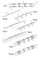
- FIG. 1is a perspective view of an elongate structure with a steerable end in a particular embodiment of the invention
- FIGS. 2 a to 2 gare fragmentary longitudinal section views of the FIG. 1 elongate structure with a steerable end, during different steps in its fabrication;
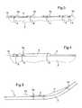
- FIG. 3is a fragmentary longitudinal section view of an elongate structure in a second embodiment of the invention.
- FIGS. 4 and 5are fragmentary longitudinal section views of a variant embodiment of a longitudinal structure shown in a rest position and in a curved position.
- FIG. 1shows a longitudinal structure 1 with a steerable end comprising a flexible longitudinal body 2 associated with an actuator member that includes an SMAW 4 extending along the body 2 .
- the SMAWextends inside a certain number of tubes 5 a , 5 b , 5 c , 5 d that are secured to the body 2 by ligaments 7 .
- all of the tubesare crimped on the SMAW 4 .
- the tubesare electrically conductive, and the end tubes 5 a and 5 d are connected to electrical power supply wires enabling the SMAW 4 to be heated by the Joule effect, thereby causing it to contract and thus causing the portion of the body 2 along which the SMAW 4 extends to bend.
- the starting materialis a sheath 5 of rigid conductive material
- the sheathis cut out as shown in FIG. 2 b so as to leave tubular segments 5 a to 5 d that are connected together by ligaments 7 .
- the SMAW 4is put into place inside the tubes 5 so that the SMAW extends through all of the tubes, and then the electrical power supply wires 10 are put into place by engaging their ends in the end tubes 5 a and 5 d , respectively.
- the assemblyis secured to the body 2 by means of ligatures 6 that extend to clamp against the tubes 5 a , 5 b , 5 c , and 5 d . It can be seen that for the end tubes 5 a and 5 d , the ligatures 6 extend in the crimping indentations 9 , thereby preventing said tubes from moving axially relative to the body 2 .
- the ligaments 7are removed, leaving behind only the tubes 5 a to 5 d of the initial sheath. This ensures that the tubes are properly in alignment with one another while they are being secured to the flexible longitudinal body 2 .
- the end tubes 5 a and 5 dare crimped onto the ends of the SMAW 4 thus serving to anchor it on the body 2 . They also provide electrical connections between the SMAW 4 and the electrical power supply wires 10 . In contrast the intermediate tubes 5 b and 5 c form journals for guiding the SMAW 4 during its controlled contractions and expansions.
- This embodimentmay be subjected to numerous variants, some of which are shown in FIGS. 3 and 4 .
- the ligatures 6may clamp a plurality of tubes each associated with a distinct SMAW 4 .
- the intermediate tubesmay themselves be crimped onto the SMAW 4 .
- a tubular portion 8 of the sheathmay be allowed to remain so as to extend one of the tubes in order to stiffen the body 2 locally.
- a tubular portion 8has been allowed to remain that extends the tube 5 a , and the end of the portion is attached by ligature to the body 2 .
- the body 2can no longer bend in register with the tubular portion 8 , but only in the portions along which the SMAW is left free of any guidance.
- an extension in the form of a tubular portion 8contributes to reducing the radius of curvature of the body while it is bending since the bending becomes concentrated in the above-mentioned portions, for a given length of SMAW.
- end tubes 5 a and 5 dmay be extended inwardly, i.e. towards the other tubes as shown in the figures, or outwardly. Similarly, it is possible to extend the intermediate tubes.
- the length of the extension 8is less than five times the diameter of the longitudinal body 2 so that its overall flexibility remains sufficient to avoid hindering progress of the body 2 .
- the tubesare secured to the body by ligatures, it is possible to use other securing means, such as adhesive.
- the tubesare made of an electrically conductive material, this is not essential even though it does facilitate making connections between the SMAW and the electrical power supply wires. If the tubes are of a diameter that is sufficient to enable the SMAW and a corresponding power supply wire to be superposed inside each of the end tubes, then electrical contact is established between them by the pressure applied by the crimping.
- the tubesare made by being cut out from a common sheath, which greatly facilitates manipulation of the SMAW and its positioning on the body of the structure, it is possible instead to make use of a plurality of tubes through which a single SMAW is threaded and including at least two end tubes.
Landscapes
- Health & Medical Sciences (AREA)
- Life Sciences & Earth Sciences (AREA)
- Surgery (AREA)
- Engineering & Computer Science (AREA)
- Heart & Thoracic Surgery (AREA)
- Biophysics (AREA)
- Veterinary Medicine (AREA)
- Public Health (AREA)
- General Health & Medical Sciences (AREA)
- Animal Behavior & Ethology (AREA)
- Biomedical Technology (AREA)
- Medical Informatics (AREA)
- Physics & Mathematics (AREA)
- Molecular Biology (AREA)
- Radiology & Medical Imaging (AREA)
- Pathology (AREA)
- Optics & Photonics (AREA)
- Nuclear Medicine, Radiotherapy & Molecular Imaging (AREA)
- Pulmonology (AREA)
- Anesthesiology (AREA)
- Hematology (AREA)
- Manufacturing & Machinery (AREA)
- Endoscopes (AREA)
- Surgical Instruments (AREA)
- Media Introduction/Drainage Providing Device (AREA)
- Instruments For Viewing The Inside Of Hollow Bodies (AREA)
Abstract
Description
- inserting the SMAW in tubes including at least two end tubes;
- crimping at least the end tubes onto the ends of the SMAW; and
- securing the tubes to the body in such a manner that the wire extends along the body.
Claims (6)
Applications Claiming Priority (3)
| Application Number | Priority Date | Filing Date | Title |
|---|---|---|---|
| FR1052119AFR2957807B1 (en) | 2010-03-24 | 2010-03-24 | METHOD FOR MANUFACTURING A SOFT ALLOY STRUCTURE WITH AN ADJUSTABLE END |
| FR1052119 | 2010-03-24 | ||
| PCT/EP2011/001472WO2011116961A1 (en) | 2010-03-24 | 2011-03-24 | Process for manufacturing a flexible elongate structure having an orientable end |
Publications (2)
| Publication Number | Publication Date |
|---|---|
| US20130000100A1 US20130000100A1 (en) | 2013-01-03 |
| US9084871B2true US9084871B2 (en) | 2015-07-21 |
Family
ID=42542800
Family Applications (1)
| Application Number | Title | Priority Date | Filing Date |
|---|---|---|---|
| US13/636,208Active2032-05-05US9084871B2 (en) | 2010-03-24 | 2011-03-24 | Process for manufacturing a flexible elongate structure having an orientable end |
Country Status (5)
| Country | Link |
|---|---|
| US (1) | US9084871B2 (en) |
| EP (1) | EP2549911B1 (en) |
| JP (1) | JP5491674B2 (en) |
| FR (1) | FR2957807B1 (en) |
| WO (1) | WO2011116961A1 (en) |
Families Citing this family (3)
| Publication number | Priority date | Publication date | Assignee | Title |
|---|---|---|---|---|
| JP2015024030A (en)* | 2013-07-26 | 2015-02-05 | 株式会社アライ・メッドフォトン研究所 | Medical device and optical radiation probe mounting kit for medical device |
| WO2018083762A1 (en) | 2016-11-02 | 2018-05-11 | オリンパス株式会社 | Variable stiffness actuator |
| DE102021113038A1 (en) | 2021-05-19 | 2022-11-24 | Embocraft GmbH | Implant with actively triggerable shape change |
Citations (11)
| Publication number | Priority date | Publication date | Assignee | Title |
|---|---|---|---|---|
| US4753223A (en)* | 1986-11-07 | 1988-06-28 | Bremer Paul W | System for controlling shape and direction of a catheter, cannula, electrode, endoscope or similar article |
| US4790624A (en)* | 1986-10-31 | 1988-12-13 | Identechs Corporation | Method and apparatus for spatially orienting movable members using shape memory effect alloy actuator |
| US4944727A (en) | 1986-06-05 | 1990-07-31 | Catheter Research, Inc. | Variable shape guide apparatus |
| US5025799A (en)* | 1987-05-13 | 1991-06-25 | Wilson Bruce C | Steerable memory alloy guide wires |
| US5090956A (en)* | 1983-10-31 | 1992-02-25 | Catheter Research, Inc. | Catheter with memory element-controlled steering |
| US5135517A (en)* | 1990-07-19 | 1992-08-04 | Catheter Research, Inc. | Expandable tube-positioning apparatus |
| WO1995006494A1 (en) | 1993-09-03 | 1995-03-09 | Intelliwire, Inc. | Device with adjustable stiffness and bend location |
| US6672338B1 (en)* | 1998-12-14 | 2004-01-06 | Masayoshi Esashi | Active slender tubes and method of making the same |
| US7416534B2 (en)* | 2004-06-22 | 2008-08-26 | Boston Scientific Scimed, Inc. | Medical device including actuator |
| US20100069882A1 (en)* | 2008-09-18 | 2010-03-18 | Boston Scientific Scimed, Inc. | Medical device with preferential bending |
| US20100168666A1 (en)* | 2008-12-31 | 2010-07-01 | Tegg Troy T | Catheter Having Independently-Deflectable Segments and Method of its Manufacture |
- 2010
- 2010-03-24FRFR1052119Apatent/FR2957807B1/enactiveActive
- 2011
- 2011-03-24JPJP2013500391Apatent/JP5491674B2/enactiveActive
- 2011-03-24WOPCT/EP2011/001472patent/WO2011116961A1/enactiveApplication Filing
- 2011-03-24USUS13/636,208patent/US9084871B2/enactiveActive
- 2011-03-24EPEP11710712.8Apatent/EP2549911B1/enactiveActive
Patent Citations (11)
| Publication number | Priority date | Publication date | Assignee | Title |
|---|---|---|---|---|
| US5090956A (en)* | 1983-10-31 | 1992-02-25 | Catheter Research, Inc. | Catheter with memory element-controlled steering |
| US4944727A (en) | 1986-06-05 | 1990-07-31 | Catheter Research, Inc. | Variable shape guide apparatus |
| US4790624A (en)* | 1986-10-31 | 1988-12-13 | Identechs Corporation | Method and apparatus for spatially orienting movable members using shape memory effect alloy actuator |
| US4753223A (en)* | 1986-11-07 | 1988-06-28 | Bremer Paul W | System for controlling shape and direction of a catheter, cannula, electrode, endoscope or similar article |
| US5025799A (en)* | 1987-05-13 | 1991-06-25 | Wilson Bruce C | Steerable memory alloy guide wires |
| US5135517A (en)* | 1990-07-19 | 1992-08-04 | Catheter Research, Inc. | Expandable tube-positioning apparatus |
| WO1995006494A1 (en) | 1993-09-03 | 1995-03-09 | Intelliwire, Inc. | Device with adjustable stiffness and bend location |
| US6672338B1 (en)* | 1998-12-14 | 2004-01-06 | Masayoshi Esashi | Active slender tubes and method of making the same |
| US7416534B2 (en)* | 2004-06-22 | 2008-08-26 | Boston Scientific Scimed, Inc. | Medical device including actuator |
| US20100069882A1 (en)* | 2008-09-18 | 2010-03-18 | Boston Scientific Scimed, Inc. | Medical device with preferential bending |
| US20100168666A1 (en)* | 2008-12-31 | 2010-07-01 | Tegg Troy T | Catheter Having Independently-Deflectable Segments and Method of its Manufacture |
Non-Patent Citations (1)
| Title |
|---|
| International Search Report of PCT/EP2011/001472 dated Jun. 29, 2011. |
Also Published As
| Publication number | Publication date |
|---|---|
| US20130000100A1 (en) | 2013-01-03 |
| FR2957807B1 (en) | 2012-03-23 |
| EP2549911A1 (en) | 2013-01-30 |
| WO2011116961A1 (en) | 2011-09-29 |
| FR2957807A1 (en) | 2011-09-30 |
| JP5491674B2 (en) | 2014-05-14 |
| JP2013521960A (en) | 2013-06-13 |
| EP2549911B1 (en) | 2019-11-13 |
Similar Documents
| Publication | Publication Date | Title |
|---|---|---|
| US11986606B2 (en) | Instrument for endoscopic applications | |
| US9833149B2 (en) | Methods, apparatus and systems for facilitating introduction of shaped medical instruments into the body of a subject | |
| US20060247619A1 (en) | Medical device with procedure improvement features | |
| US11812993B2 (en) | Flexible torque cable for delivery of medical devices | |
| US9084871B2 (en) | Process for manufacturing a flexible elongate structure having an orientable end | |
| US11338110B2 (en) | Flexible elongated structure having a steerable end | |
| US20210353130A1 (en) | Steerable elongated functional system | |
| US20210290915A1 (en) | Guide wire | |
| EP3831437B1 (en) | Anchoring elements for a steerable device and assembly method thereof | |
| JP5951268B2 (en) | Medical tube and method for manufacturing medical tube | |
| TW202539574A (en) | A tubular body of a steerable surgical arm for use in endoscopes during surgical procedures and a method of making the same | |
| HK30080290A2 (en) | A method of making a steerable surgical arm for use in endoscopes during surgical procedures | |
| JP2006122311A (en) | Guide wire |
Legal Events
| Date | Code | Title | Description |
|---|---|---|---|
| AS | Assignment | Owner name:CENTRE NATIONAL DE LA RECHERCHE SCIENTIFIQUE, FRAN Free format text:ASSIGNMENT OF ASSIGNORS INTEREST;ASSIGNOR:SZEWCZYK, JEROME;REEL/FRAME:029005/0647 Effective date:20120110 Owner name:UNIVERSITE PIERRE ET MARIE CURIE (PARIS 6), FRANCE Free format text:ASSIGNMENT OF ASSIGNORS INTEREST;ASSIGNOR:SZEWCZYK, JEROME;REEL/FRAME:029005/0647 Effective date:20120110 | |
| FEPP | Fee payment procedure | Free format text:PAYOR NUMBER ASSIGNED (ORIGINAL EVENT CODE: ASPN); ENTITY STATUS OF PATENT OWNER: LARGE ENTITY | |
| STCF | Information on status: patent grant | Free format text:PATENTED CASE | |
| FEPP | Fee payment procedure | Free format text:PAYER NUMBER DE-ASSIGNED (ORIGINAL EVENT CODE: RMPN); ENTITY STATUS OF PATENT OWNER: LARGE ENTITY Free format text:PAYOR NUMBER ASSIGNED (ORIGINAL EVENT CODE: ASPN); ENTITY STATUS OF PATENT OWNER: LARGE ENTITY | |
| AS | Assignment | Owner name:SORBONNE UNIVERSITE, FRANCE Free format text:MERGER;ASSIGNOR:UNIVERSITE PIERRE ET MARIE CURIE (PARIS 6);REEL/FRAME:045953/0583 Effective date:20180320 | |
| AS | Assignment | Owner name:SORBONNE UNIVERSITE, FRANCE Free format text:CORRECTIVE ASSIGNMENT TO CORRECT THE ASSIGNEE'S ADDRESS PREVIOUSLY RECORDED ON REEL 045953 FRAME 0583. ASSIGNOR(S) HEREBY CONFIRMS THE MERGER;ASSIGNOR:UNIVERSITE PIERRE ET MARIE CURIE (PARIS 6);REEL/FRAME:047331/0847 Effective date:20180320 | |
| AS | Assignment | Owner name:SATT LUTECH, FRANCE Free format text:LICENSE;ASSIGNORS:UNIVERSITE PIERRE ET MARIE CURIE (PARIS 6);CENTRE NATIONAL DE LA RECHERCHE SCIENTIFIQUE;REEL/FRAME:047736/0232 Effective date:20141218 | |
| MAFP | Maintenance fee payment | Free format text:PAYMENT OF MAINTENANCE FEE, 4TH YEAR, LARGE ENTITY (ORIGINAL EVENT CODE: M1551); ENTITY STATUS OF PATENT OWNER: LARGE ENTITY Year of fee payment:4 | |
| MAFP | Maintenance fee payment | Free format text:PAYMENT OF MAINTENANCE FEE, 8TH YEAR, LARGE ENTITY (ORIGINAL EVENT CODE: M1552); ENTITY STATUS OF PATENT OWNER: LARGE ENTITY Year of fee payment:8 |