US9084850B2 - Dialysis catheter - Google Patents
Dialysis catheterDownload PDFInfo
- Publication number
- US9084850B2 US9084850B2US13/947,088US201313947088AUS9084850B2US 9084850 B2US9084850 B2US 9084850B2US 201313947088 AUS201313947088 AUS 201313947088AUS 9084850 B2US9084850 B2US 9084850B2
- Authority
- US
- United States
- Prior art keywords
- catheter
- lumen
- wall
- lumens
- dialysis
- Prior art date
- Legal status (The legal status is an assumption and is not a legal conclusion. Google has not performed a legal analysis and makes no representation as to the accuracy of the status listed.)
- Expired - Fee Related
Links
- 238000000502dialysisMethods0.000titleclaimsabstractdescription71
- 239000008280bloodSubstances0.000claimsabstractdescription45
- 210000004369bloodAnatomy0.000claimsabstractdescription45
- 230000007704transitionEffects0.000claimsabstractdescription29
- 238000003780insertionMethods0.000claimsdescription56
- 230000037431insertionEffects0.000claimsdescription56
- 210000001519tissueAnatomy0.000description41
- 238000000034methodMethods0.000description35
- 210000004731jugular veinAnatomy0.000description27
- 239000000463materialSubstances0.000description26
- 210000005245right atriumAnatomy0.000description24
- 206010033675panniculitisDiseases0.000description20
- 210000004304subcutaneous tissueAnatomy0.000description20
- 210000002620vena cava superiorAnatomy0.000description19
- 125000006850spacer groupChemical class0.000description17
- 230000017531blood circulationEffects0.000description14
- 239000003351stiffenerSubstances0.000description14
- 239000012530fluidSubstances0.000description11
- 238000004891communicationMethods0.000description8
- 210000003734kidneyAnatomy0.000description7
- 238000004519manufacturing processMethods0.000description7
- 230000015572biosynthetic processEffects0.000description6
- 238000000576coating methodMethods0.000description6
- 238000001631haemodialysisMethods0.000description6
- 230000000322hemodialysisEffects0.000description6
- 230000008569processEffects0.000description6
- 230000005641tunnelingEffects0.000description6
- 238000013459approachMethods0.000description5
- 239000011248coating agentSubstances0.000description5
- 230000032258transportEffects0.000description5
- 230000000916dilatatory effectEffects0.000description4
- 229910052751metalInorganic materials0.000description4
- 239000002184metalSubstances0.000description4
- 239000002699waste materialSubstances0.000description4
- 238000012974catheter insertion methodMethods0.000description3
- 230000007423decreaseEffects0.000description3
- 238000001746injection mouldingMethods0.000description3
- 230000007935neutral effectEffects0.000description3
- 239000003053toxinSubstances0.000description3
- 231100000765toxinToxicity0.000description3
- 108700012359toxinsProteins0.000description3
- 206010001526Air embolismDiseases0.000description2
- 102000009123FibrinHuman genes0.000description2
- 108010073385FibrinProteins0.000description2
- BWGVNKXGVNDBDI-UHFFFAOYSA-NFibrin monomerChemical compoundCNC(=O)CNC(=O)CNBWGVNKXGVNDBDI-UHFFFAOYSA-N0.000description2
- 230000002411adverseEffects0.000description2
- 238000003491arrayMethods0.000description2
- 230000008859changeEffects0.000description2
- 230000003247decreasing effectEffects0.000description2
- 238000013461designMethods0.000description2
- 239000000385dialysis solutionSubstances0.000description2
- 230000010339dilationEffects0.000description2
- 229950003499fibrinDrugs0.000description2
- 238000010438heat treatmentMethods0.000description2
- 208000015181infectious diseaseDiseases0.000description2
- 238000002347injectionMethods0.000description2
- 239000007924injectionSubstances0.000description2
- 208000014674injuryDiseases0.000description2
- 239000012528membraneSubstances0.000description2
- 238000000465mouldingMethods0.000description2
- 210000000885nephronAnatomy0.000description2
- 230000009467reductionEffects0.000description2
- 230000003014reinforcing effectEffects0.000description2
- 238000000926separation methodMethods0.000description2
- 239000002904solventSubstances0.000description2
- 239000000126substanceSubstances0.000description2
- 238000004381surface treatmentMethods0.000description2
- 230000008733traumaEffects0.000description2
- 230000000472traumatic effectEffects0.000description2
- 210000001631vena cava inferiorAnatomy0.000description2
- OKTJSMMVPCPJKN-UHFFFAOYSA-NCarbonChemical compound[C]OKTJSMMVPCPJKN-UHFFFAOYSA-N0.000description1
- JOYRKODLDBILNP-UHFFFAOYSA-NEthyl urethaneChemical compoundCCOC(N)=OJOYRKODLDBILNP-UHFFFAOYSA-N0.000description1
- HTTJABKRGRZYRN-UHFFFAOYSA-NHeparinChemical compoundOC1C(NC(=O)C)C(O)OC(COS(O)(=O)=O)C1OC1C(OS(O)(=O)=O)C(O)C(OC2C(C(OS(O)(=O)=O)C(OC3C(C(O)C(O)C(O3)C(O)=O)OS(O)(=O)=O)C(CO)O2)NS(O)(=O)=O)C(C(O)=O)O1HTTJABKRGRZYRN-UHFFFAOYSA-N0.000description1
- 208000001647Renal InsufficiencyDiseases0.000description1
- 241000907903ShoreaSpecies0.000description1
- FOIXSVOLVBLSDH-UHFFFAOYSA-NSilver ionChemical compound[Ag+]FOIXSVOLVBLSDH-UHFFFAOYSA-N0.000description1
- FAPWRFPIFSIZLT-UHFFFAOYSA-MSodium chlorideChemical compound[Na+].[Cl-]FAPWRFPIFSIZLT-UHFFFAOYSA-M0.000description1
- 208000007536ThrombosisDiseases0.000description1
- XSQUKJJJFZCRTK-UHFFFAOYSA-NUreaChemical compoundNC(N)=OXSQUKJJJFZCRTK-UHFFFAOYSA-N0.000description1
- 239000000853adhesiveSubstances0.000description1
- 230000001070adhesive effectEffects0.000description1
- 239000003146anticoagulant agentSubstances0.000description1
- 230000000903blocking effectEffects0.000description1
- 238000010241blood samplingMethods0.000description1
- 239000004202carbamideSubstances0.000description1
- 229910052799carbonInorganic materials0.000description1
- 238000004140cleaningMethods0.000description1
- 230000006835compressionEffects0.000description1
- 238000007906compressionMethods0.000description1
- 238000005520cutting processMethods0.000description1
- 230000007812deficiencyEffects0.000description1
- 230000002950deficientEffects0.000description1
- 230000000994depressogenic effectEffects0.000description1
- 238000009792diffusion processMethods0.000description1
- 238000002224dissectionMethods0.000description1
- 239000003814drugSubstances0.000description1
- 229940079593drugDrugs0.000description1
- 238000012377drug deliveryMethods0.000description1
- 230000029142excretionEffects0.000description1
- 238000001914filtrationMethods0.000description1
- 239000003292glueSubstances0.000description1
- 229960002897heparinDrugs0.000description1
- 229920000669heparinPolymers0.000description1
- 230000006872improvementEffects0.000description1
- 239000003112inhibitorSubstances0.000description1
- 229910052500inorganic mineralInorganic materials0.000description1
- 201000006370kidney failureDiseases0.000description1
- 230000014759maintenance of locationEffects0.000description1
- 230000013011matingEffects0.000description1
- 230000008590mechanical hemolysisEffects0.000description1
- 238000002844meltingMethods0.000description1
- 230000008018meltingEffects0.000description1
- 239000011707mineralSubstances0.000description1
- 239000000203mixtureSubstances0.000description1
- 230000004048modificationEffects0.000description1
- 238000012986modificationMethods0.000description1
- 210000000056organAnatomy0.000description1
- 238000003825pressingMethods0.000description1
- 230000037452primingEffects0.000description1
- 230000000750progressive effectEffects0.000description1
- 150000003839saltsChemical class0.000description1
- 238000005549size reductionMethods0.000description1
- 239000011780sodium chlorideSubstances0.000description1
- 239000007779soft materialSubstances0.000description1
- 239000011343solid materialSubstances0.000description1
- 229910001220stainless steelInorganic materials0.000description1
- 239000010935stainless steelSubstances0.000description1
- 210000001321subclavian veinAnatomy0.000description1
- 238000007920subcutaneous administrationMethods0.000description1
- 238000001356surgical procedureMethods0.000description1
- 210000000779thoracic wallAnatomy0.000description1
- 230000002537thrombolytic effectEffects0.000description1
- 230000002792vascularEffects0.000description1
- XLYOFNOQVPJJNP-UHFFFAOYSA-NwaterSubstancesOXLYOFNOQVPJJNP-UHFFFAOYSA-N0.000description1
Images


Classifications
- A—HUMAN NECESSITIES
- A61—MEDICAL OR VETERINARY SCIENCE; HYGIENE
- A61M—DEVICES FOR INTRODUCING MEDIA INTO, OR ONTO, THE BODY; DEVICES FOR TRANSDUCING BODY MEDIA OR FOR TAKING MEDIA FROM THE BODY; DEVICES FOR PRODUCING OR ENDING SLEEP OR STUPOR
- A61M1/00—Suction or pumping devices for medical purposes; Devices for carrying-off, for treatment of, or for carrying-over, body-liquids; Drainage systems
- A61M1/14—Dialysis systems; Artificial kidneys; Blood oxygenators ; Reciprocating systems for treatment of body fluids, e.g. single needle systems for hemofiltration or pheresis
- A61M1/30—Single needle dialysis ; Reciprocating systems, alternately withdrawing blood from and returning it to the patient, e.g. single-lumen-needle dialysis or single needle systems for hemofiltration or pheresis
- A—HUMAN NECESSITIES
- A61—MEDICAL OR VETERINARY SCIENCE; HYGIENE
- A61M—DEVICES FOR INTRODUCING MEDIA INTO, OR ONTO, THE BODY; DEVICES FOR TRANSDUCING BODY MEDIA OR FOR TAKING MEDIA FROM THE BODY; DEVICES FOR PRODUCING OR ENDING SLEEP OR STUPOR
- A61M1/00—Suction or pumping devices for medical purposes; Devices for carrying-off, for treatment of, or for carrying-over, body-liquids; Drainage systems
- A61M1/36—Other treatment of blood in a by-pass of the natural circulatory system, e.g. temperature adaptation, irradiation ; Extra-corporeal blood circuits
- A61M1/3621—Extra-corporeal blood circuits
- A61M1/3653—Interfaces between patient blood circulation and extra-corporal blood circuit
- A61M1/3659—Cannulae pertaining to extracorporeal circulation
- A61M1/3661—Cannulae pertaining to extracorporeal circulation for haemodialysis
- A—HUMAN NECESSITIES
- A61—MEDICAL OR VETERINARY SCIENCE; HYGIENE
- A61M—DEVICES FOR INTRODUCING MEDIA INTO, OR ONTO, THE BODY; DEVICES FOR TRANSDUCING BODY MEDIA OR FOR TAKING MEDIA FROM THE BODY; DEVICES FOR PRODUCING OR ENDING SLEEP OR STUPOR
- A61M25/00—Catheters; Hollow probes
- A61M25/0021—Catheters; Hollow probes characterised by the form of the tubing
- A61M25/0023—Catheters; Hollow probes characterised by the form of the tubing by the form of the lumen, e.g. cross-section, variable diameter
- A61M25/0026—Multi-lumen catheters with stationary elements
- A61M25/003—Multi-lumen catheters with stationary elements characterized by features relating to least one lumen located at the distal part of the catheter, e.g. filters, plugs or valves
- A—HUMAN NECESSITIES
- A61—MEDICAL OR VETERINARY SCIENCE; HYGIENE
- A61M—DEVICES FOR INTRODUCING MEDIA INTO, OR ONTO, THE BODY; DEVICES FOR TRANSDUCING BODY MEDIA OR FOR TAKING MEDIA FROM THE BODY; DEVICES FOR PRODUCING OR ENDING SLEEP OR STUPOR
- A61M25/00—Catheters; Hollow probes
- A61M25/0021—Catheters; Hollow probes characterised by the form of the tubing
- A61M25/0023—Catheters; Hollow probes characterised by the form of the tubing by the form of the lumen, e.g. cross-section, variable diameter
- A61M25/0026—Multi-lumen catheters with stationary elements
- A61M25/0032—Multi-lumen catheters with stationary elements characterized by at least one unconventionally shaped lumen, e.g. polygons, ellipsoids, wedges or shapes comprising concave and convex parts
- A—HUMAN NECESSITIES
- A61—MEDICAL OR VETERINARY SCIENCE; HYGIENE
- A61M—DEVICES FOR INTRODUCING MEDIA INTO, OR ONTO, THE BODY; DEVICES FOR TRANSDUCING BODY MEDIA OR FOR TAKING MEDIA FROM THE BODY; DEVICES FOR PRODUCING OR ENDING SLEEP OR STUPOR
- A61M25/00—Catheters; Hollow probes
- A61M25/0043—Catheters; Hollow probes characterised by structural features
- A—HUMAN NECESSITIES
- A61—MEDICAL OR VETERINARY SCIENCE; HYGIENE
- A61M—DEVICES FOR INTRODUCING MEDIA INTO, OR ONTO, THE BODY; DEVICES FOR TRANSDUCING BODY MEDIA OR FOR TAKING MEDIA FROM THE BODY; DEVICES FOR PRODUCING OR ENDING SLEEP OR STUPOR
- A61M39/00—Tubes, tube connectors, tube couplings, valves, access sites or the like, specially adapted for medical use
- A61M39/22—Valves or arrangement of valves
- A61M39/28—Clamping means for squeezing flexible tubes, e.g. roller clamps
- A61M39/284—Lever clamps
- A—HUMAN NECESSITIES
- A61—MEDICAL OR VETERINARY SCIENCE; HYGIENE
- A61M—DEVICES FOR INTRODUCING MEDIA INTO, OR ONTO, THE BODY; DEVICES FOR TRANSDUCING BODY MEDIA OR FOR TAKING MEDIA FROM THE BODY; DEVICES FOR PRODUCING OR ENDING SLEEP OR STUPOR
- A61M25/00—Catheters; Hollow probes
- A61M25/0021—Catheters; Hollow probes characterised by the form of the tubing
- A61M25/0023—Catheters; Hollow probes characterised by the form of the tubing by the form of the lumen, e.g. cross-section, variable diameter
- A61M25/0026—Multi-lumen catheters with stationary elements
- A61M25/003—Multi-lumen catheters with stationary elements characterized by features relating to least one lumen located at the distal part of the catheter, e.g. filters, plugs or valves
- A61M2025/0031—Multi-lumen catheters with stationary elements characterized by features relating to least one lumen located at the distal part of the catheter, e.g. filters, plugs or valves characterized by lumina for withdrawing or delivering, i.e. used for extracorporeal circuit treatment
- A—HUMAN NECESSITIES
- A61—MEDICAL OR VETERINARY SCIENCE; HYGIENE
- A61M—DEVICES FOR INTRODUCING MEDIA INTO, OR ONTO, THE BODY; DEVICES FOR TRANSDUCING BODY MEDIA OR FOR TAKING MEDIA FROM THE BODY; DEVICES FOR PRODUCING OR ENDING SLEEP OR STUPOR
- A61M25/00—Catheters; Hollow probes
- A61M25/0021—Catheters; Hollow probes characterised by the form of the tubing
- A61M25/0023—Catheters; Hollow probes characterised by the form of the tubing by the form of the lumen, e.g. cross-section, variable diameter
- A61M25/0026—Multi-lumen catheters with stationary elements
- A61M2025/0034—Multi-lumen catheters with stationary elements characterized by elements which are assembled, connected or fused, e.g. splittable tubes, outer sheaths creating lumina or separate cores
- A—HUMAN NECESSITIES
- A61—MEDICAL OR VETERINARY SCIENCE; HYGIENE
- A61M—DEVICES FOR INTRODUCING MEDIA INTO, OR ONTO, THE BODY; DEVICES FOR TRANSDUCING BODY MEDIA OR FOR TAKING MEDIA FROM THE BODY; DEVICES FOR PRODUCING OR ENDING SLEEP OR STUPOR
- A61M25/00—Catheters; Hollow probes
- A61M25/0021—Catheters; Hollow probes characterised by the form of the tubing
- A61M25/0023—Catheters; Hollow probes characterised by the form of the tubing by the form of the lumen, e.g. cross-section, variable diameter
- A61M25/0026—Multi-lumen catheters with stationary elements
- A61M2025/0036—Multi-lumen catheters with stationary elements with more than four lumina
- A—HUMAN NECESSITIES
- A61—MEDICAL OR VETERINARY SCIENCE; HYGIENE
- A61M—DEVICES FOR INTRODUCING MEDIA INTO, OR ONTO, THE BODY; DEVICES FOR TRANSDUCING BODY MEDIA OR FOR TAKING MEDIA FROM THE BODY; DEVICES FOR PRODUCING OR ENDING SLEEP OR STUPOR
- A61M25/00—Catheters; Hollow probes
- A61M25/0021—Catheters; Hollow probes characterised by the form of the tubing
- A61M25/0023—Catheters; Hollow probes characterised by the form of the tubing by the form of the lumen, e.g. cross-section, variable diameter
- A61M25/0026—Multi-lumen catheters with stationary elements
- A61M2025/0037—Multi-lumen catheters with stationary elements characterized by lumina being arranged side-by-side
- A—HUMAN NECESSITIES
- A61—MEDICAL OR VETERINARY SCIENCE; HYGIENE
- A61M—DEVICES FOR INTRODUCING MEDIA INTO, OR ONTO, THE BODY; DEVICES FOR TRANSDUCING BODY MEDIA OR FOR TAKING MEDIA FROM THE BODY; DEVICES FOR PRODUCING OR ENDING SLEEP OR STUPOR
- A61M25/00—Catheters; Hollow probes
- A61M25/0021—Catheters; Hollow probes characterised by the form of the tubing
- A61M25/0023—Catheters; Hollow probes characterised by the form of the tubing by the form of the lumen, e.g. cross-section, variable diameter
- A61M25/0026—Multi-lumen catheters with stationary elements
- A61M2025/004—Multi-lumen catheters with stationary elements characterized by lumina being arranged circumferentially
- A—HUMAN NECESSITIES
- A61—MEDICAL OR VETERINARY SCIENCE; HYGIENE
- A61M—DEVICES FOR INTRODUCING MEDIA INTO, OR ONTO, THE BODY; DEVICES FOR TRANSDUCING BODY MEDIA OR FOR TAKING MEDIA FROM THE BODY; DEVICES FOR PRODUCING OR ENDING SLEEP OR STUPOR
- A61M25/00—Catheters; Hollow probes
- A61M25/0021—Catheters; Hollow probes characterised by the form of the tubing
- A61M25/0023—Catheters; Hollow probes characterised by the form of the tubing by the form of the lumen, e.g. cross-section, variable diameter
- A61M25/0026—Multi-lumen catheters with stationary elements
- A61M25/0028—Multi-lumen catheters with stationary elements characterized by features relating to at least one lumen located at the proximal part of the catheter, e.g. alterations in lumen shape or valves
- A—HUMAN NECESSITIES
- A61—MEDICAL OR VETERINARY SCIENCE; HYGIENE
- A61M—DEVICES FOR INTRODUCING MEDIA INTO, OR ONTO, THE BODY; DEVICES FOR TRANSDUCING BODY MEDIA OR FOR TAKING MEDIA FROM THE BODY; DEVICES FOR PRODUCING OR ENDING SLEEP OR STUPOR
- A61M5/00—Devices for bringing media into the body in a subcutaneous, intra-vascular or intramuscular way; Accessories therefor, e.g. filling or cleaning devices, arm-rests
- A61M5/14—Infusion devices, e.g. infusing by gravity; Blood infusion; Accessories therefor
- A61M5/1414—Hanging-up devices
- A61M5/1418—Clips, separators or the like for supporting tubes or leads
- Y—GENERAL TAGGING OF NEW TECHNOLOGICAL DEVELOPMENTS; GENERAL TAGGING OF CROSS-SECTIONAL TECHNOLOGIES SPANNING OVER SEVERAL SECTIONS OF THE IPC; TECHNICAL SUBJECTS COVERED BY FORMER USPC CROSS-REFERENCE ART COLLECTIONS [XRACs] AND DIGESTS
- Y10—TECHNICAL SUBJECTS COVERED BY FORMER USPC
- Y10T—TECHNICAL SUBJECTS COVERED BY FORMER US CLASSIFICATION
- Y10T24/00—Buckles, buttons, clasps, etc.
- Y10T24/44—Clasp, clip, support-clamp, or required component thereof
- Y10T24/44641—Clasp, clip, support-clamp, or required component thereof having gripping member formed from, biased by, or mounted on resilient member
- Y10T24/44744—Clasp, clip, support-clamp, or required component thereof having gripping member formed from, biased by, or mounted on resilient member with position locking-means for engaging faces
- Y10T24/44752—Integral locking-means
- Y—GENERAL TAGGING OF NEW TECHNOLOGICAL DEVELOPMENTS; GENERAL TAGGING OF CROSS-SECTIONAL TECHNOLOGIES SPANNING OVER SEVERAL SECTIONS OF THE IPC; TECHNICAL SUBJECTS COVERED BY FORMER USPC CROSS-REFERENCE ART COLLECTIONS [XRACs] AND DIGESTS
- Y10—TECHNICAL SUBJECTS COVERED BY FORMER USPC
- Y10T—TECHNICAL SUBJECTS COVERED BY FORMER US CLASSIFICATION
- Y10T24/00—Buckles, buttons, clasps, etc.
- Y10T24/44—Clasp, clip, support-clamp, or required component thereof
- Y10T24/44641—Clasp, clip, support-clamp, or required component thereof having gripping member formed from, biased by, or mounted on resilient member
- Y10T24/44744—Clasp, clip, support-clamp, or required component thereof having gripping member formed from, biased by, or mounted on resilient member with position locking-means for engaging faces
- Y10T24/44761—Pivoted lock member
Definitions
- This applicationrelates to a catheter and more particularly to a multi-lumen catheter which facilitates hemodialysis.
- Hemodialysisis a well known method of providing renal (kidney) function by circulating blood.
- the kidneysare organs which function to extract water and urea, mineral salts, toxins, and other waste products from the blood with filtering units called nephrons. From the nephrons the collected waste is sent to the bladder for excretion.
- the hemodialysis procedureis life saving because it provides a machine to simulate the function of the kidneys.
- hemodialysisblood is withdrawn from the patient's body through a catheter or tube and transported to a dialysis machine, also commonly referred to as a kidney machine.
- the catheteris typically inserted through the jugular vein and maneuvered into position through the superior vena cava into the right atrium to provide high blood flow.
- toxins and other waste productsdiffuse through a semi-permeable membrane into a dialysis fluid closely matching the chemical composition of the blood.
- the filtered bloodi.e. with the waste products removed, is then returned to the patient's body.
- the cathetermay be left in place for several years. As can be appreciated, proper access to the patient's blood and transport of the blood to and from the dialysis machine for this extended period of time is critical to hemodialysis.
- MedComp Ash Split catheterOne example of a dialysis catheter currently being marketed is the MedComp Ash Split catheter.
- This catheterhas two lumens, one for arterial flow and the other for venous flow, which are each D-shaped in cross-sectional configuration.
- the catheteris bifurcated at its distal end to separate the lumens and the catheter is manually split to the desired length for selected separation before insertion into the target area.
- Another well-known catheteris a Med Comp catheter which has the venous flow lumen terminating proximally, i.e. axially recessed, from the arterial flow lumen. Each of these lumens is also D-shaped in cross-sectional configuration.
- an introducer needleis inserted through a first incision site (first opening) to properly locate (access) the vessel, e.g. the right internal jugular vein;
- a guide wireis inserted through the needle into the internal jugular vein and down through the superior vena cava into the inferior vena cava;
- a tear away (peel away) sheath and dilatorare inserted over the guidewire and through the first incision site to provide an access port for the dialysis catheter into the jugular vein, superior vena cava and right atrium;
- a second incisionis made in the chest wall to create a second opening
- a trocaris attached to the distal end of the dialysis catheter
- the trocar and dialysis catheterare pushed through the second incision and advanced to bluntly dissect the subcutaneous tissue to exit the first incision (opening) which was created by the introducer needle, thereby creating a subcutaneous tissue tunnel between the first and second openings;
- the trocaris detached from the dialysis catheter leaving the catheter in place extending from the second opening, through the tissue tunnel and out the first opening;
- the dialysis catheterwhich is protruding from the first incision, is inserted through the tear away sheath and advanced so its distal portion is positioned in the right atrium;
- the sheathis separated, i.e. split, by pulling the tabs apart, and then pulled upwardly away from the dialysis catheter and removed from the body, leaving the catheter in place;
- the second incisionis closed and the dialysis catheter, which is connected through tubes to the dialysis machine, is left in place an extended period of time to provide blood circulation to and from the dialysis machine.
- the trocarcan be forced through a third incision exiting adjacent the first incision, and then the catheter inserted through second and third incisions and through the introducer sheath positioned in the first incision.
- the use of the tear away sheathis also potentially problematic.
- the tear-away sheathhas lines of weakness to separate it as it is pulled apart by the pull tabs to enable removal of the sheath.
- the sheathcan potentially cause damage to the vessel wall as it is being pulled apart and can cause infection.
- pulling the sheath laterallycan enlarge the incision, thereby increasing the difficulty of closing the incision at the end of the procedure.
- the sheathsince the sheath is pulled in the proximal direction for removal, it could pull the catheter proximally as well, thereby pulling it away from the desired site, and requiring repositioning.
- the edges of the tear awaycan also lacerate the surgeon's glove and finger. Over dilation by the sheath can cause blood leakage.
- a dialysis catheter insertion methodcould be provided which reduces some of the foregoing procedural steps, thereby decreasing the complexity of the procedure and decreasing the hospital and surgeon costs. It would also be advantageous if such dialysis catheter insertion method could be provided which would be less traumatic and avoid the foregoing problems associated with the use of a tear-away sheath, such as increased risk of air embolism, trauma to the vessel wall, incision enlargement and dislodgement of the catheter.
- Dialysis cathetersare composed of flexible tubing to minimize damage to the vessel wall during insertion and use. This flexibility, however, oftentimes results in kinking of the catheter since the catheter must navigate curves to reach the target vessel. This kinking can adversely affect blood flow. Also, the catheter needs to have some degree of stiffness to enable directing the catheter around the curves of the vessels. The stiffness, however provides its own risks since if the catheter is not properly directed, the catheter can inadvertently be forced against the vessel wall, thereby puncturing or damaging the vessel.
- the smallest catheter profilei.e. the smallest outer diameter catheter body.
- This profilefacilitates insertion through smaller vessels as it reduces the likelihood of the catheter engaging the wall of the vessel and reduces trauma to the vessel by minimizing frictional contact with the vessel wall.
- the desire for smaller diameter cathetersmust be balanced against the need for providing sufficient sized lumens to enable proper blood flow. If the lumens are too small, sufficient blood flow may not be able to be maintained and the blood can be damaged during transport. Also, a sufficient relationship must be maintained between the size of the lumens and the overall diameter of the catheter to maintain the structural integrity of the catheter.
- dialysis cathetersAnother important feature of dialysis catheters is the suction openings to withdraw blood. Keeping the suction openings clear of thrombolytic material and away from the vessel wall is clearly essential to dialysis function since an adequate supply of blood must be removed from the patient to be dialyzed.
- a problem with prior dialysis cathetersis that during blood withdrawal, as suction is being applied through the catheter openings and lumen, the suction can cause the catheter to be forced against the side wall of the vessel, known as “side port occlusion”, which can block the opening and adversely affect the function of the catheter by enabling only intermittent suction. In fact, the opening can become completely blocked, thereby preventing necessary intake of blood, i.e. venous flow.
- Fibrin sheath growth around the outside of the cathetercan occur since dialysis catheters are oftentimes implanted for several months or even years. This fibrin growth, caused by the body's attempt to reject the catheter as a foreign body, could result in blocking of the suction holes.
- Such catheterwould advantageously reduce the catheter insertion time, simplify the catheter insertion process, eliminate the need for a peel-away introducer sheath, decrease the chances of infection, reduce unwanted kinking of the catheter during insertion, strike an optimal balance between overall catheter and lumen size, and improve the suction capability to avoid hampering of blood flow.
- the present inventionprovides a dialysis catheter comprising a first portion having a first diameter, an elongated distal portion having a second diameter smaller than the first diameter, and a transition region between the first portion and distal portion.
- a first longitudinally extending central lumenconfigured to deliver blood terminates in an opening in the distal portion.
- At least two independent longitudinally extending lumensare positioned radially of the first lumen, configured to withdraw blood from a patient, and terminate in a longitudinally directed opening in the transition region.
- the transition regiontapers toward the distal portion and preferably at least a portion of the wall thickness of the catheter in the distal portion tapers toward a distalmost end with the central lumen cross-sectional area remaining substantially constant throughout its length in the distal portion.
- the cathetermay further comprise a stiffening member removably positionable within the catheter to temporarily increase the stiffness of the catheter to facilitate insertion.
- the present inventionalso provides a medical catheter comprising a first return lumen, a plurality of withdrawal lumens, a first clamping member and a plurality of intake extension tubes.
- Each intake extension tubecommunicates with an intake lumen of the catheter to provide fluid communication with the respective intake lumens.
- the intake extension tubesare positioned in a stacked arrangement, and the clamping member has a plurality of posts to receive the stacked tubes to limit lateral movement thereof.
- the catheterpreferably further comprises an independent venous extension tube communicating with the return lumen of the catheter.
- the catheterincludes a first tag connected to the first clamping member and a second tag connected to the second clamping member to provide information to the user.
- the first tagincludes first and second side walls and a bridge extending between the first and second side walls and the second tag includes first and second sidewalls and a bridge extending between the first and second sidewalls.
- the present inventionalso provides in combination a clamping member and a plurality of extension tubes of a medical catheter for delivering and withdrawing blood from a patient's body.
- the plurality of intake extension tubeseach communicate with an intake lumen of the catheter to provide fluid communication with the respective intake lumens.
- the intake extension tubesare positioned in a stacked arrangement.
- the clamping memberhas a plurality of posts to receive the stacked tubes to limit lateral movement thereof.
- the combinationfurther includes a luer and an adapter interposed between the plurality of intake extension tubes and the luer.
- the adapterhas three openings arranged in a triangular arrangement to receive and reorient the extension tubes.
- a first tagis connected to the clamping member to provide information to the user.
- the tagin one embodiment comprises a first and second side wall and a bridge extending between the first and second side walls.
- the first clamping memberin one embodiment has a pair of proximal posts and a pair of distal posts spaced axially from the proximal posts.
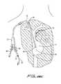
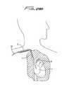
- FIG. 1is a plan view of a first embodiment of the multi-lumen catheter of the present invention being inserted through the right internal jugular vein and superior vena cava into the right atrium of a patient's body;
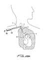
- FIG. 2is a plan view illustrating the multi-lumen catheter of FIG. 1 being inserted through the left internal jugular vein and superior vena cava into the right atrium;
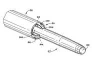
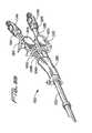
- FIG. 3is an isometric view of the first embodiment of the multi-lumen catheter of the present invention and showing the direction of insertion of the stiffening rod;
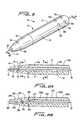
- FIG. 4Ais a side view of a first embodiment of a stiffening rod of the present invention insertable through the catheter of FIG. 3 to facilitate catheter insertion;
- FIG. 4Bis a side view of an alternate embodiment of the stiffening rod of the present invention having a series of mounting threads at its distal end;
- FIG. 5is perspective view of the distal portion of the multi-lumen catheter of FIG. 3 and showing a guidewire extending through the central lumen;
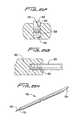
- FIG. 6Ais a longitudinal cross-sectional view taken along lines 6 A- 6 A of FIG. 5 ;
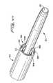
- FIG. 6Bis a longitudinal cross-sectional view similar to FIG. 6A except showing an alternate embodiment of the catheter having internal threads for securing the stiffening rod of FIG. 4B ;
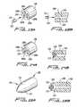
- FIG. 7is a transverse cross sectional view taken along lines 7 - 7 of FIG. 6A ;
- FIG. 8is a transverse cross sectional view taken along lines 8 - 8 of FIG. 6A :
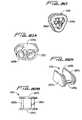
- FIG. 9Ais a transverse cross-sectional view similar to FIG. 8 except showing a second alternate embodiment of the lumen configuration of the catheter of the present invention.
- FIG. 9Bis a transverse cross-sectional view similar to FIG. 8 except showing a third embodiment of the lumen configuration of the catheter of the present invention.
- FIG. 9Cis a transverse cross-sectional view similar to FIG. 8 except showing a fourth embodiment of the lumen configuration of the catheter of the present invention.
- FIG. 10is a transverse cross-sectional view similar to FIG. 8 except showing a fifth embodiment of the lumen configuration of the catheter of the present invention.
- FIG. 12is a longitudinal cross sectional view similar to FIG. 11 except showing the stiffening rod fully positioned within the central lumen, in abutment with the stop in the distal tip;
- FIGS. 13-15illustrate an alternate embodiment of the distal tip of the catheter of the present invention and the method steps for forming the tip wherein:
- FIGS. 13A and 13Bare perspective and cross-sectional views, respectively, of the tip before formation shown receiving a stiffening insert
- FIGS. 14A and 14Bare perspective and cross-sectional views, respectively, of the tip once the stiffening inserted has been placed therein;
- FIGS. 15A and 15Bare perspective and cross-sectional views, respectively, of the distal tip formed into a bullet nose configuration and showing side holes formed therein;
- FIG. 16Ais a perspective view of a distal portion of another alternate embodiment of the multi-lumen catheter of the present invention having a series of spacer wires and showing a guidewire extending therethrough;
- FIG. 16Bis a longitudinal cross-sectional view of the distal portion catheter of FIG. 16A showing the spacer wires in the extended position;
- FIG. 16Cis a longitudinal cross-sectional view similar to FIG. 16A except showing the profile of the spacing wires and catheter body reduced as the stiffening rod of FIG. 4A is inserted into the central lumen over the guidewire to stretch the catheter during insertion;
- FIG. 17Ais a perspective view of a distal portion of yet another alternate embodiment of the catheter having a series of integral spacer ribs;
- FIG. 17Bis a longitudinal cross-sectional view of the distal portion of catheter of FIG. 17 showing the spacer ribs in the extended position;
- FIG. 17Cis a longitudinal cross-sectional view similar to FIG. 17A except showing the profile of the spacer ribs and catheter body reduced as the stiffening rod of FIG. 4A is inserted into the central lumen to stretch the catheter during insertion;
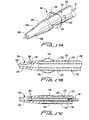
- FIG. 18is a perspective view of a distal portion of another alternate embodiment of the multi-lumen catheter of the present invention having a tapered tip;
- FIG. 19is a longitudinal cross-sectional view of the distal portion of the catheter of FIG. 18 showing the stiffening rod positioned through the central lumen of the catheter over the guidewire;
- FIG. 21Ais a perspective view of a first embodiment of a trocar of the present invention having a barbed proximal end for attachment to the catheter for creating a subcutaneous tissue tunnel and for pulling the catheter through the tissue tunnel;
- FIG. 21Bis a perspective exploded view of an alternate embodiment of the trocar of FIG. 21A having a removable handle;
- FIG. 21Dis a close up view of an alternate embodiment of the trocar having a threaded connecting structure
- FIG. 21Eis a perspective view of the trocar of FIG. 21B being inserted through a subcutaneous tissue tunnel;
- FIG. 21Fis a transverse cross-sectional view taken along lines 4 - 4 of FIG. 21E showing the latch for releasably connecting the trocar of FIG. 21B to the handle;
- FIG. 21Gis a cross-sectional view showing the threaded connection of the trocar of FIG. 21D to the handle;
- FIG. 21Jis a perspective view of an alternate embodiment of a trocar with a proximal end configured for insertion into a distal end of the catheter;
- FIG. 21Kis an enlarged side view of the proximal end of the trocar of FIG. 21J ;
- FIG. 21Lis a perspective view showing insertion of the trocar of FIG. 21J into the distal end of the catheter;
- FIG. 22illustrates an alternate embodiment of the trocar of the present invention having a lumen for receiving a guidewire
- FIG. 23illustrates the trocar of FIG. 22 being withdrawn after a subcutaneous tissue tunnel has been created
- FIG. 24Bis a longitudinal cross-sectional view of the distal end portion of the trocar of FIG. 24A ;
- FIGS. 25-28illustrate the surgical method steps for inserting the multi-lumen catheter of FIG. 3 through the right internal jugular vein and superior vena cava into the right atrium wherein:
- FIG. 25shows the introducer needle being inserted through the right jugular vein and the guidewire being inserted through the right jugular vein, through the superior vena cava and into the right atrium;
- FIG. 26illustrates the needle introducer removed leaving the guidewire in place in the right internal jugular vein, superior vena cava and right atrium;
- FIG. 27illustrates the trocar of FIG. 22 being inserted through a first incision site and exiting a second incision site to create a subcutaneous tissue tunnel adjacent the incision site for the introducer needle;
- FIG. 28Aillustrates the guidewire being threaded through the lumen of the trocar of FIG. 22 ;
- FIG. 28Billustrates the trocar being removed, leaving the guidewire in place extending through the tissue tunnel
- FIG. 28Cillustrates the multi-lumen catheter of FIG. 3 inserted over the guidewire through the tissue tunnel, and curved down into the right internal jugular vein, superior vena cava and right atrium;
- FIGS. 29A-29Gillustrate the steps for an alternate method of inserting the multi-lumen catheter of FIG. 3 through the right internal jugular vein and superior vena cava into the right atrium wherein the trocar creates a tissue tunnel with an exit opening at the incision cite where the needle and guidewire are introduced, wherein:
- FIG. 29Aillustrates the trocar of FIG. 22 inserted over the guidewire through a first incision site, creating a subcutaneous tissue tunnel, and exiting the incision site created for insertion of the introducer needle and guidewire;
- FIG. 29Billustrates the trocar being removed, leaving the guidewire in place extending through the tissue tunnel and forming a loop adjacent the needle incision site;
- FIG. 29Cillustrates the multi-lumen catheter of FIG. 3 being inserted over the guidewire for passage through the tissue tunnel;
- FIG. 29Dillustrates the catheter inserted through the subcutaneous tissue tunnel and forming a loop corresponding to the loop formed in the guidewire
- FIG. 29Eillustrates the catheter extending through the subcutaneous tissue tunnel and being inserted further along the guidewire down into the right internal jugular vein
- FIG. 29Fis a view similar to FIG. 29E except showing the guidewire being removed.
- FIG. 29Gillustrates the catheter in place extending through the subcutaneous tissue tunnel and advanced into the right internal jugular vein, superior vena cava and right atrium;
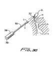
- FIG. 30illustrates an alternate method of retracting the guidewire through the subcutaneous tissue tunnel formed by the trocar
- FIGS. 31-37illustrate a method for manufacturing a first embodiment of the hub of the multi-lumen catheter of FIG. 3 wherein:
- FIG. 31illustrates a slit formed in the outer wall of the catheter
- FIG. 32is a view similar to FIG. 31 except showing in phantom the central arterial lumen of the catheter;
- FIG. 33is a transverse cross-sectional view taken along lines 33 - 33 of FIG. 32 ;
- FIG. 34illustrates a pin inserted through the slit in the outer wall of the catheter
- FIG. 35illustrates the tubing inserted over the pin
- FIG. 36illustrates the injection of soft material over the pin and catheter tube to form the catheter hub which retains the lumen connector tubes in position;
- FIG. 37illustrates the hub resulting from the injection molding process enabling one connector to communicate with the inflow (arterial) lumen and the other connector to communicate with the multiple outflow (venous) lumens;
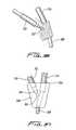
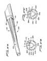
- FIGS. 38-40illustrate an alternate embodiment of the hub of the multi-lumen catheter of FIG. 3 wherein;
- FIG. 38illustrates a perspective view of the proximal end of the catheter body split into five segments to accommodate the separate connector tubes;
- FIG. 39is a perspective view illustrating the connector tubes inserted into the respective lumens of the catheter body.
- FIG. 40is a transverse cross-sectional view illustrating the cuts made in the catheter wall to form the separate segments.
- FIG. 41is a perspective view of another alternate embodiment of the hub of the catheter of the present invention having the lumen configuration of FIG. 9C ;
- FIG. 42is an exploded view of the hub and tube structure of FIG. 41 ;
- FIG. 43is an enlarged perspective view showing the transition of the venous holes from a substantially oval to a substantially round configuration at the flared proximal portion of the catheter.
- FIG. 44is an enlarged perspective view showing the multi-lumen extension tube tapering proximally and transitioning from substantially circular venous holes to substantially triangular holes;
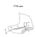
- FIGS. 45-54illustrate an alternate preferred embodiment of the dialysis catheter of the present invention, wherein
- FIG. 46is a perspective view similar to FIG. 45 except showing the stiffener rod positioned therein;
- FIG. 47is an enlarged perspective view of the catheter tip showing the return and intake lumen openings
- FIG. 48is a side view of the catheter tip
- FIGS. 48A , 48 B and 48 Care transverse cross-sectional views taken along lines A-A, B-B and C-C, respectively, of FIG. 48 ;
- FIG. 49Ais a longitudinal cross-sectional view of a distal portion of the catheter showing the stiffener rod extending through the catheter;
- FIG. 49Bis a side view of the stiffener rod of FIG. 49A ;
- FIG. 50is a perspective view showing the arterial extension tubes extending from the proximal flared portion of the catheter, the venous extension tube is removed for clarity;
- FIG. 51is a side view of the proximal end of the catheter, with one of the hub halves removed, showing the extension tubing connections to the catheter lumens;
- FIG. 52is a perspective view of a proximal portion of the arterial extension tubing illustrating the funneled surfaces for wire insertion;
- FIG. 53is a transverse cross-sectional view taken along lines D-D of FIG. 46 showing the lead in for the cleaning wire insertion.
- FIG. 54is a transverse cross-sectional view taken along lines E-E of FIG. 50 showing the arterial extension tubes within the sheath.
- FIG. 55is a perspective view of the proximal end portion of an alternate embodiment of the catheter of the present invention showing the extension tubing and clamps;
- FIG. 56is an exploded view of the catheter of FIG. 55 ;
- FIG. 57Ais a perspective view of a distal end portion of the catheter.
- FIG. 57Bis a transverse cross-sectional view illustrating the lumen configuration of one embodiment of the catheter.
- FIG. 57Cis a transverse cross-sectional view illustrating the lumen configuration of an alternate embodiment of the catheter.
- FIGS. 58A and 58Bare side and perspective views, respectively, of the arterial clamp shown in the open position;
- FIGS. 59A and 59Bare perspective and top views, respectively, of the arterial tag
- FIG. 60is a perspective view of the adapter
- FIG. 64is an enlarged view of the venous clamp shown in the neutral position and further showing a portion of the arterial clamp.
- FIG. 1illustrates the catheter 10 inserted through the right internal jugular vein “a”, into the superior vena cava “b”, and into the right atrium “c”;
- FIG. 2illustrates the catheter 10 inserted into the left internal jugular vein “d”, into the superior vena cava “b” and into the right atrium “c”. Insertion into the right atrium, from either the right or left side provides the necessary high blood flow to the dialysis machine.
- the catheter body (catheter tube) 11is sufficiently flexible to enable it to bend to accommodate the anatomical curves as shown.
- Catheter 10has a catheter body or catheter tube 11 having a distal end portion 31 , a proximal end portion 33 , and an intermediate portion 35 .
- Distal portion 31terminates in nose 32 which is illustratively substantially conical in shape.
- Proximal end portion 33includes hub 12 , where the lumens formed within catheter tube 11 are connected, i.e. transition, to the respective inflow and outflow tubes, 16 , 18 , respectively, to enable return and withdrawal of blood for dialysis.
- Conventional tube clamps 17 and 19cut off blood flow through inflow and outflow tubes 16 , 18 as desired.
- inflowand “outflow” refer to the direction of blood flow with respect to the catheter such that “return”, “delivery” or “venous flow” refers to flow from the dialysis machine and delivered to the body while “intake”, “withdrawal” or “arterial flow” refers to flow withdrawn from the body and transported to the dialysis machine.
- intermediate portion of catheter 10extends through subcutaneous tissue tunnel “t”, and curves downwardly toward the target site, e.g. the right atrium.
- This tunnel “t”secures the catheter in place for dialysis for a period of weeks, or even months, with fibrous cuff 36 ( FIG. 3 ) enabling tissue ingrowth.
- fibrous cuff 36FIG. 3
- the catheteris shown emerging from the tissue tunnel “t” at a second incision site, preferably, the tissue tunnel would not have an exit opening at a second site but instead would exit through the same incision through which initial access is made by the needle and dilator into the internal jugular vein “a”. This is described in more detail below.
- lumen 40 , lumen 41 and narrowed lumen 45together form a central lumen enabling blood to be delivered from the dialysis machine to the patient.
- the transition from lumen 41 into narrowed lumen 45forms a stop or shoulder 43 , the function of which will be described below.
- Nose 42also includes side venous (delivery) openings 46 formed through the outer wall 44 wall in fluid communication with lumen 41 , also functioning to return blood to the patient's body.
- Side openings or ports 46are preferably angled outwardly as shown to facilitate delivery of blood in the direction of blood flow and lessen mechanical hemolysis. These additional openings help maintain the desired flow volume by distributing the blood through multiple holes. Although only four openings are shown, it is contemplated that additional or fewer openings can be provided and the openings can be axially displaced with respect to each other. Additional set(s) of openings can also be provided spaced proximally or distally from side openings 46 .
- nose 42forms the distal tip portion and is composed of a different material than the other portions of the catheter body 11 and is welded or attached by other means to the catheter body 11 .
- the tip (nose) in this embodimentis composed of a stiffer material to facilitate tunneling and blunt dissection through tissue.
- the nosecould alternatively be composed of a softer material, thereby being less traumatic upon contact with the vessel wall.
- the noseis composed of the same material as the catheter body, having a small stiffener member embedded therein. This configuration is described in detail below in conjunction with FIGS. 13-15 .
- the lumens 34 a - eare independent from one another through the distal, intermediate and proximal portions 33 , 35 , 31 of the catheter body 11 , until the hub 12 where the lumens 34 a - 34 e connect to a common connector tube. This is described in more detail below.
- Lumens 34 a - 34 eas shown, are symmetrically positioned and radially displaced from the central return lumen 40 .
- a series of side openings or ports 50are provided in the outer wall 14 of catheter body 10 .
- These openings 50 a , 50 b , 50 c , 50 d , and 50 eare each in fluid communication with a respective intake lumen 34 a - 34 e and are designed and configured to withdraw blood from the patient's body for delivery to the dialysis machine.
- a second set of openings 52 a - 52 espaced proximally from openings 50 a - 50 e , is also in communication with a respective lumen 34 a - 34 e . Only three of the side openings 50 , 52 are shown in FIG. 5 , it being understood that the other three openings are positioned on the other side of the catheter, preferably symmetrically placed to accommodate the circumferential arrangement of the intake lumens 34 a - 34 e.
- lumens 34 a - 34 eare isolated along a substantial length of the catheter, they preferably have a common flow source at the proximal portion 33 of the catheter 10 . This is described in more detail below.
- the other pair of opposing wallshas a slight curvature.
- four oval-like intake lumens 76 a , 76 b , 76 c and 76 dare positioned around a substantially square central lumen 78 .
- This lumen configurationprovides for a substantially sized central lumen and sufficient room between the central lumen 78 and each of the intake lumens 76 a - 76 d for the catheter walls to flex.
- five lumens 70 a - 70 e of circular cross-sectionare provided around the central lumen 40 ′′, adding to the stability of the catheter by increasing the wall material, but reducing the overall venous lumen size as compared to the embodiment of FIG. 8 .
- the intake (arterial) lumens in each of these embodimentsare independent from one another along the substantial length of the catheter.
- lumens of other configurationsare also contemplated.
- the openings in the sidewalls communicating with the lumenscan also be elongated instead of circular, creating a series of longitudinally extending openings for entry of suctioned blood. This version of elongated openings is shown for example in FIGS. 18 and 20 described in detail below.
- the proximal end portion 85 of stiffening rod 80has a threaded portion 81 which is screwed onto screw thread 15 of inflow tube 16 . This temporarily secures the stiffening rod 80 within the catheter 10 during insertion.
- This threaded mountingrequires the stiffening rod 80 to be manually twisted, thereby torquing rod 80 as it presses forwardly and applies a force against shoulder (abutment surface) 43 to stretch the catheter body 11 to reduce its outer diameter.
- the catheter body 11can be reduced in diameter from about 0.215 millimeters to about 0.207 millimeters by the stiffening rod 80 . (Other size reductions are also contemplated). This reduction in catheter body diameter or profile is represented by the arrows D 1 and D 2 in FIGS. 11 and 12 , respectively, which show the change in dimension effectuated by the stiffener rod 80 .
- the stiffening rod 80is unthreaded from the proximal thread 15 of venous (return) tube 16 and removed from the central lumen 40 of the catheter 10 and from the venous (return) tube 16 , thereby allowing the catheter to return to its normal profile of FIG. 11 .
- FIG. 4BAn alternate embodiment of the stiffening rod is illustrated in FIG. 4B and designated generally by reference numeral 90 .
- Stiffening rod 90has a threaded distal end 92 which is threaded onto internal threads 251 of catheter 200 shown in FIG. 6B .
- a series of proximal threads 91are screwed onto the threads 15 of the inflow tube 16 in the same manner as described above for stiffener rod 80 .
- the stiffening rod 90functions in the same manner as stiffening rod 80 , i.e.
- the distal threads 92are first threaded onto internal thread 251 , followed by attachment of the proximal threads 91 as the stiffening rod 90 is torqued.
- Stiffening rod 90like stiffening rod 80 , is preferably circular in cross-section, although other configurations are also contemplated.
- Catheter 200 of FIG. 6Bis identical to catheter 200 in all respects except for the threads 251 instead of shoulder 43 and lumen 241 which is uniform in diameter. Similar to catheter 10 , catheter 200 has distal return opening 247 and side openings 246 in outer wall 244 communicating with lumen 241 in distal tip portion 242 , which communicates with central lumen 40 . Arterial intake lumens 234 a - 234 e terminate at wall 248 and have respective side openings 252 a - 252 e and 250 s - 250 e formed in the outer wall 214 . Only one of the side openings 250 a , 252 a are shown in the longitudinal cross-sectional view of FIG. 6B .
- distal tipcan be composed of a different stiffer material than the catheter body 11 or can be composed of a material having a higher durometer than the catheter body. This stiffer material will facilitate both tunneling through and dilating tissue. In an alternate preferred embodiment, however, the distal tip is composed of the same material as the catheter body but has a stiffening insert.
- FIG. 15the alternative nose (tip) configuration is illustrated in FIG. 15 , with the method of manufacturing the tip shown in FIGS. 13 and 14 .
- This nose or distal tip 104is composed of the same material as the catheter body 108 and has a stiffening insert 110 inserted through central lumen 106 of nose 104 . Central lumen 106 extends through the catheter body.
- the stiffening insert 110is preferably composed of the same material as the catheter body 11 and nose 104 , except it is made of a harder durometer material such as 72 shoreD vs. 85 shoreA for the catheter body 11 .
- the material utilizedcan be, by way of example, urethane. For convenience, only the distal tip is shown, the remaining portions of the catheter 100 being identical to catheter 10 .
- the stiffening insert 110preferably cylindrical as shown, has a hole 112 for receipt of the guidewire and for communication with central lumen 106 . Insert 110 engages the inner wall surface 114 of central lumen 106 .
- Lumen 106proximal of side openings 119 , will include either a stepped portion to provide an abutment surface (shoulder) for stiffening rod 80 or internal threads to mount stiffening rod 90 as described above.
- stiffening insert 110is placed within central lumen 106 at the distalmost end and substantially flush with the distalmost edge 102 of the cylindrical tube.
- the tubeis formed into the bullet nose shape of FIGS. 15A and 15B , by a conventional radiofrequency or other heating process which allows the tip material to flow and form around the harder insert 110 .
- the materialis cooled and thereby hardens to the configuration of FIG. 15 as the material fuses to the insert 110 .
- a conventional core pin(not shown) can be used, inserted through the hole 112 and central lumen 106 during the forming process. When the material hardens, the pin is withdrawn to maintain these openings.
- side holes 114are either cut or drilled through the wall 108 of catheter 100 to communicate with lumen 106 in the same manner as side holes 46 communicate with central lumen 40 of FIGS. 1-6 .
- FIGS. 16A-17Cillustrate two alternate embodiments of the catheter of the present invention having spacers to minimize contact of the catheter body with the vessel wall. Provision of these spacers is optional.
- catheter 150similar to catheter 10 , has a distal portion having a nose 154 , a central return lumen 156 which also receives a guidewire 20 , and a series (e.g. 5) of intake lumens 160 - 160 .
- Venous return lumen 156communicates with lumen 151 and narrowed lumen 153 of the nose 154 , terminating in open distal end 158 .
- a plurality of side openings 159communicate with lumen 151 and function in the same manner as side openings 46 of catheter 10 .
- Arterial intake lumens 160each terminate at side openings 161 , similar to side openings 52 of intake lumens 34 of catheter 10 .
- side openings 161are shown, clearly additional arrays of side openings, positioned distally or proximally of side openings 161 could be provided.
- the arterial lumen configurationcan also vary in a similar manner as described above with respect to catheter 10 .
- catheter 150is identical to catheter 10 .
- a plurality of spacer wires 164are embedded in the wall 169 of the catheter 150 and are secured at region 158 by adhesive or other suitable means. In the normal configuration, spacer wires 164 bow slightly outwardly with respect to the outer wall 169 of the catheter 150 to reduce the likelihood of contact with the vessel wall.
- the stiffening rod 80is inserted over guidewire 20 and through central lumen 156 , as shown in FIG. 16C , and edge 170 is forced against the abutment surface or stop 159 , the catheter body is stretched and the spacer wires 164 stretch to a straightened position, substantially flush with the outer surface of wall 169 . This reduces the profile of the catheter and ensures the spacer wires do not interfere with catheter insertion.
- stiffening rod 90can also be used with catheter 150 and would function to reduce the profile in the same manner as rod 80 .
- Catheter 150would then be provided with internal threads for mounting stiffening rod 90 as described above.
- FIGS. 17A-17CAn alternative to spacer wires is illustrated in FIGS. 17A-17C .
- Catheter 180is identical to catheter 150 , except it is provided with integral ribs 194 proximal of nose 184 . That is, similar to catheter 150 , catheter 180 has a central return lumen 186 configured to receive guidewire 20 and stiffening rod 80 or 90 . Lumen 186 communicates with lumen 181 and narrowed lumen 183 of the nose 184 which terminates in open distal end 188 . Side openings 189 of nose 184 communicate with lumen 181 .
- a series of independent intake lumens 190are provided, terminating in side openings 192 , similar to side openings 161 of catheter 150 . Although only one series of side openings 192 are shown, clearly additional arrays, positioned proximally or distally of side openings 192 could be provided.
- FIGS. 18 and 19illustrate another alternative embodiment of the catheter of the present invention.
- Catheter 500has a distal tip 502 with a tapered region 510 transitioning to a reduced diameter region 504 .
- the central lumenterminates in distal opening 506 for fluid delivery.
- the distal opening 506is the sole fluid delivery passageway into the body.
- additional side holescould be provided in the tip to provide additional venous ports for blood delivery to the patient.
- a series of intake (arterial) openings 508are provided in the transition or tapered region 510 of the tip 502 . These openings are elongated to provide additional area for suctioning. Each of the openings 508 communicates with a respective arterial lumen 510 formed in the catheter.
- the venous lumen configuration(and arterial lumen configuration) can be in the form of those illustrated in FIGS. 7-10 , or other variations, as described above.
- Stiffening rod 520is shown positioned in the central lumen of the catheter 500 .
- Rod 520is similar to the rods 80 and 90 described above except it extends distally of the distal tip 502 of catheter 500 , has a tapered distal end 524 to facilitate tunneling and dilating tissue, and has a stepped portion to abut the internal structure of the catheter 500 .
- guidewire 20is shown extending through the central lumen of stiffening rod 520 .
- the stiffening rod 520is inserted through the central lumen of catheter 500 and the stiffening rod 520 and catheter 500 are inserted over the guidewire 20 , with the tapered tip 524 facilitating passage of the catheter as it dilates tissue.
- FIG. 20illustrates an alternative tip design of the catheter of the present invention.
- Catheter tip 602has a bullet nose configuration, somewhat similar to the nose of FIG. 15 , except having more of a progressive taper.
- Catheter tip 602also has a series of elongated intake holes 608 (only two are shown in the view of FIG. 20 ).
- catheter 600is identical to catheter 500 of FIG. 18 .
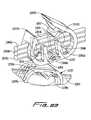
- the distal portion 812 of catheter 800is elongated and has a diameter less than the diameter of the intermediate portion 816 .
- the diameter of the distal portion 812can be about 0.118 inches and the diameter of the intermediate portion 816 can be about 0.218 inches. Clearly other dimensions are contemplated.
- the transition portion 814provides a smooth transition between the intermediate portion 816 and the distal portion 812 as it tapers in a distal direction. Formed in the transition portion 814 are four widened somewhat trapezoidal open areas, separated by ribs 849 , each extending longitudinally to communicate with the intake openings. Thus, the intake openings terminate in longitudinally aligned openings at the transition portion 814 .
- a stiffening insert 820similar to the cylindrical stiffening insert 110 described in conjunction with FIGS. 13A-15B , except it is located proximal of the distalmost tip.
- the stiffening insert 820is placed during formation of the catheter tube by melting the catheter material around the insert during formation in a similar fashion as insert 110 .
- FIG. 48illustrates the lumen configuration of the catheter 800 which is similar to the lumen configurations of FIG. 9C .
- a central return (venous) lumen 830is encircled by a series of intake lumens 840 a - 840 d in a spoke-like fashion.
- the central return lumen 830is substantially square in cross-section with rounded corners as shown in FIG. 48A .
- the four intake lumens 840 a - 840 dare oval-like in cross section with a substantially planar edge 842 a - 842 d and opposing inwardly angled side walls.
- the central lumen 830terminates in opening 832 at the distalmost end of the catheter tube 810 .
- the intake lumensare independent and each terminates in an open area 844 a - 844 d in the transition region 814 as described above.
- the central return lumen 830is of substantially constant cross-sectional area throughout its length. At the distal portion 812 the lumen 830 transitions to a more circular shape ( FIG. 48B ), but the cross-sectional area preferably remains the same. In a preferred embodiment, the cross-sectional area of the central lumen is about 0.007 inches 2 , although other dimensions are contemplated. At the flared portion 821 ( FIG. 50 ) the return lumen 830 transitions to a more circular configuration.
- the intake lumens 840 a - 840 dremain constant throughout their length until the proximal flared portion 821 where they are substantially circular ( FIG. 50 ) and of greater cross-sectional area to receive the arterial extension tubes described below.
- the intake lumens 840 a - 840 dtransition to a more arcuate shape, as shown in FIG. 48B , just proximal of the transition region 814 , but the cross-sectional area preferably remains the same.
- This lumen configurationis similar to that of FIG. 9A in that it is more of a trapezoidal than oval shape with curved walls and inwardly angled substantially straight side walls).
- the cross-sectional area of each intake lumen 840is preferably about 0.003 inches 2 so that the total intake cross-sectional area is preferably about 0.012 inches 2 , but other dimensions for the intake lumens are contemplated.
- a connector tube or insert 854preferably of stainless steel, is inserted into the central lumen 830 and a tapered venous extension tube 856 is placed over the tube 854 to provide fluid communication between extension tube 856 and central lumen 830 .
- the two hub halves 860 , 862 of hub 861are snapped fitted over the region containing flared portion 821 , connector tube 854 , and a portion of extension tubes 850 a - 850 d , 856 and sleeve 852 as shown in FIG. 51 .
- Conventional arterial and venous clamps C 1 , C 2are illustrated in FIG. 45 .
- a conventional suture ring 870( FIG. 45 ), having suture holes for attaching the catheter, is fitted in an annular groove in the hub 861 .
- a conventional fibrous cuff 872 for tissue ingrowthis shown at an intermediate section of the catheter 810 for tissue ingrowth as described above.
- FIG. 49illustrates an embodiment of a stiffening rod for use with catheter 800 to temporarily increase the stiffness of the catheter to facilitate pushability (insertion) of the catheter.
- Stiffening rod 880has a thickened wall portion 882 which engages an internal wall in the region of the catheter adjacent the region which contains the stiffening insert 820 . Since this catheter region is not as flexible, it is not stretched at this region by the stiffener rod 880 , thus providing resistance to distal movement of the stiffening rod 880 , thereby holding it in place during insertion.
- stiffener rod 880cooperates with the distalmost tip of the catheter 800 to prevent coring of tissue during insertion.
- the stiffener 880protrudes past the distalmost tip of the catheter body 810 as shown, serving to help dilate tissue during insertion.
- Lumen 884is dimensioned to receive a guidewire.
- the arterial extension tubingincludes a funneled lead in to facilitate insertion of standard guidewires to clear obstructions, e.g. clots and thrombus, in the catheter arterial lumens which may form over time.
- each of the quadrants within the sleevehas an inwardly directed curved inner wall 892 a - d to create a funnel for the tubing entry region.
- Trocar 300has a lumen 304 formed therethrough (shown in phantom in FIG. 22 ) dimensioned for reception of guidewire 20 .
- the lumen 304extends the entire length of trocar 300 , from a proximal opening 306 in handle 308 to a distal opening 310 (shown in phantom in FIG. 22 ) on the underside of the trocar 300 as viewed in FIG. 22 .
- Distal opening 310is adjacent the distal tip 302 , at the region where it bends slightly upwardly.
- trocar 300can be smaller than the outer diameter of the dialysis catheter, e.g. catheter 10 , since it only needs to have an internal diameter of about 0.040 inches to about 0.045 inches to receive the guidewire.
- the diameter of the catheteris typically between about 0.170 inches and about 0.220 inches.
- the blunt distal tip 302 of trocar 300bluntly dissects tissue to create a subcutaneous tissue tunnel for subsequent securement of the catheter.
- FIGS. 24A and 24Billustrate an alternate embodiment of the trocar.
- Trocar 380is similar to trocar 300 except for an elongated oval entrance opening 382 to lumen 383 for the guidewire and a beveled tip 384 to facilitate tunneling through tissue.
- the handle configuration 386is also slightly different.
- FIGS. 25 to 28One method of use of the catheter will now be described in conjunction with FIGS. 25 to 28 . The method will be described for inserting catheter 10 , however it should be appreciated that any of the aforedescribed catheters can be inserted in the same manner.
- needle “N”is inserted into the internal jugular vein to properly locate the vessel and a guidewire 20 is inserted through the needle into the right internal jugular vein “a” and into the superior vena cava “b” as shown in FIG. 25 .
- the guidewire 20is further advanced into the right atrium “c”, and preferably into the inferior vena cava.
- the needle ‘N”is then withdrawn, leaving the guidewire 20 in place, extending out of the patient's body at the proximal portion 21 .
- trocar 300is inserted through a first incision “s” in the patient, bluntly dissecting and tunneling under the skin, and forced out of the tissue at a second incision or site “u”, creating a subcutaneous tunnel “t” under the tissue as shown in FIG. 27 .
- Thisprovides a way to secure the catheter as described below.
- Guidewire 20is then threaded through lumen 304 of the trocar, with proximal portion 21 first inserted through trocar distal opening 310 so it emerges out of proximal opening 306 as shown in FIG. 28A .
- Trocar 300is then withdrawn from the body in the direction of the arrow of FIG. 28B , leaving the guidewire 20 in place as shown.
- guidewire 20extends from the right atrium and superior vena cava, out through the right internal jugular vein and through the tissue tunnel “t”.
- Catheter 10is then threaded over the guidewire with the proximal portion 21 of the guidewire inserted through the distal tip lumen of the catheter, through the length of the central lumen, and through the hub 12 into the inflow tube 116 and out through fitting 15 .
- the catheter 10is thus threaded over the wire, through the tissue tunnel “t” where cuff 36 (not shown in FIG. 28C ) is positioned in the tissue tunnel “t” to aid in securement of the catheter by enabling tissue ingrowth over a period of time.
- the catheteris further advanced over guidewire 20 down into the right internal jugular vein, into the superior vena cava, and into the right atrium.
- the guidewire 20is withdrawn in the direction of the arrow, leaving the catheter 10 in place for use as shown in FIG. 28C .
- the stiffening member 80 or 90(not shown in FIG. 28C for clarity) is preferably utilized, i.e. inserted over the guidewire 20 through the fitting 15 , inflow tube 16 , hub 12 , and central lumen 40 to help guide the catheter 10 as described above.
- the guidewire 20would extend through the central lumen of catheter by extending through the central lumen of the stiffening member which is positioned within the central lumen of the catheter.
- the catheterwill be inserted in a similar fashion through the left internal jugular vein to be positioned as depicted in FIG. 2 .
- the subcutaneous tissue tunnelwill be formed on the left side as shown in FIG. 2 , by the trocar 300 , and the catheter inserted over the guidewire through the tissue tunnel and through the left internal jugular vein or subclavian vein and into the superior vena cava and right atrium in the same way as described for right side insertion.
- any of the aforedescribed catheters of the present inventioncan be inserted in this fashion.
- FIGS. 29A-29GAn alternative method of insertion is illustrated in FIGS. 29A-29G .
- this methodinstead of forming a second incision site adjacent the incision site through which the needle and guidewire are introduced into the internal jugular vein as in FIG. 27 , the trocar 300 emerges from the needle/guidewire insertion site.
- catheter 10is shown, any of the foregoing catheters can be inserted in the same manner.
- trocar 300is inserted through a first incision (as in FIG. 27 ) to create a subcutaneous tissue tunnel; however, unlike FIG. 27 , trocar 300 does not emerge at a second incision site “u”. Instead, trocar 300 is advanced subcutaneously to the needle incision site “w”, and emerges through the site “w” as shown. Thus, as shown in FIG. 29A , the distal end of trocar 300 ′ exits incision site “w” alongside the guidewire 20 .
- Guidewire 20is then inserted (threaded) through the opening in trocar 300 as described above and then the trocar is withdrawn through the tissue tunnel ‘t” and out through the first incision “s”, pulling the guidewire 20 through the tunnel. After the guidewire 21 is pulled through the tunnel “t” and out through incision “s”, the trocar 300 is removed as shown in FIG. 29B , leaving the guidewire 20 in place. Note the guidewire 20 is positioned to form a guidewire loop 22 to facilitate insertion of the catheter as will be described below.
- the catheter 10is then advanced over the guidewire 20 ( FIG. 29C ), through the tissue tunnel, and exiting incision site “w” into the internal jugular vein “a” ( FIG. 29D ).
- the catheter 10as shown, is formed into a loop 13 , tracking the loop 22 of guidewire 20 , and then advanced downwardly through the internal jugular vein, the superior vena cava and into the right atrium ( FIG. 29E ).
- the guidewire 20is then withdrawn as shown in FIG. 29F , and the catheter is pushed downwardly and/or pulled back to straighten the loop to position the catheter as shown in FIG. 29G . If the catheter is inserted with a stiffening member, the guidewire would extend through the lumen of the stiffening member.
- FIG. 30shows an alternate embodiment of a trocar utilized to retrieve the suture and retract it through the subcutaneous tissue tunnel.
- Trocar 300 ′is similar to trocar 300 of FIG. 29 except for the provision of eyelet 312 .
- the sutureis threaded through the eyelet (shown as two small opposing holes in the wall at the distal end of the trocar 300 ′) and the trocar is pulled proximally through the tissue tunnel to pull the suture out through incision “s”.
- the trocarextends through incision “w”, the same incision created for insertion of the needle and guidewire.
- a hook or other meanscan be provided on the trocar for holding the guidewire to enable pulling the guidewire through the tissue tunnel. That is, in these versions, the guidewire is not threaded through the trocar lumen, but rather the trocar is utilized to pull (retract) the guidewire through the tissue tunnel.
- FIG. 21Aillustrates an alternative trocar used for a different approach to catheter insertion.
- This trocardesignated by reference numeral 350 , does not provide for an entire over the wire system, however it is used with an approach providing a partial over the wire system which eliminates the need for a tear way introducer sheath.
- tear away introducer sheathsare currently being utilized to guide the dialysis catheter through the vessels into the right atrium.
- the catheter in this alternate methodcan be advanced over a guidewire which can be placed in the manner illustrated in FIGS. 25 and 26 .
- trocar 350is attached to the distal end of the catheter by insertion of barbed end 352 into a mating fitting.
- Other means for temporarily attaching the trocarare also contemplated.
- Trocar 350has a blunt distal tip 354 and is advanced through a first tissue incision and out through a second tissue incision, bluntly dissecting tissue and forming a subcutaneous tissue tunnel in a similar manner as described above, except without the guidewire. Since trocar 350 is attached to the catheter, it pulls the catheter through the tissue tunnel, so it emerges out through the second incision. The trocar 350 is then detached from the catheter. The catheter is then bent as necessary and threaded over the guidewire into jugular vein, superior vena cava, and right atrium.
- FIGS. 21J-21Millustrate an alternate embodiment of the trocar used for a partial over the wire system.
- Trocar 390has a proximal end portion 392 and a distal end portion 394 .
- the distal end portionhas a dilating tip 395 to facilitate insertion through a subcutaneous tissue tunnel.
- the proximal portion 392progressively reduces in diameter toward the proximal end and has a radiused surface throughout its length to provide an interference fit with the catheter. As shown, the proximal portion 392 is inserted in the distal end of the catheter, until enlarged region 393 , which has a larger diameter than the diameter of the proximal end portion, abuts the catheter to limit insertion.
- the radiused regiondecreases in diameter (or transverse cross section toward the proximalmost end).
- the frictional engagementmaintains the attachment as the trocar 390 , with its blunt tip, dissects tissue through the tunnel to advance the catheter through the tunnel.
- the guidewirecan be threaded through the distal end and the catheter inserted over the wire into the right atrium in the same manner as described above with respect to trocar 350 .
- FIGS. 21B-21Hillustrate alternate embodiments of a trocar adapted to create a subcutaneous tissue tunnel and to subsequently be attached to a catheter.
- Trocar 900 and 920each has a removable handle which is grasped by the user and then inserted into the body to create the subcutaneous tissue tunnel. The handle provides additional leverage for facilitating trocar insertion/passage. Once inserted through the tunnel, the handle is detached and the trocar is attached to the dialysis catheter as described above, for example, with reference to trocar 350 of FIG. 21A .
- the distal endhas a dilating distal tip as described above.
- trocar 900has a connecting structure 902 on a proximal end of the elongated body 903 .
- the connecting structure 902has a circumferential groove 904 .
- Contained within the handle 906is a latch 910 having an opening 912 dimensioned to receive tip 905 of connecting structure 902 .
- the latch 910is spring biased upwardly by spring 914 so that surface 916 is seated within a groove 904 to lock the elongated body 903 within handle 906 .
- protruding region 918 of latch 910is depressed, thereby forcing surface 916 out of groove 904 and placing tip 905 in alignment with opening 912 of latch 910 (shown in phantom in FIG. 21F ).
- Thisenables the elongated body 903 of trocar 900 to be separated from the handle 906 .
- the connecting structurecan be connected to a dialysis catheter to pull the catheter through the tissue tunnel.
- the latchcan alternatively engage the recess in the barbed fitting 352 of trocar 350 of FIG. 21A .
- the connecting structure 952 extending from elongated body of trocar 950comprises series of threads 954 .
- Handle 960includes a bore with an internal thread for threaded connection to thread 954 .
- the elongated body 953 of trocar 950can be unthreaded and removed from handle 960 after creation of the tissue tunnel and then threadedly connected to the dialysis catheter.
- the threaded connectioncan be used with the trocar of FIG. 21A having a barbed fitting. This is shown in FIG. 21H .
- the threads 351are positioned distally of the barbed fitting 352 ′ with the trocar handle (not shown) having a bore with a first region dimensioned to receive the barb and having threads in a second region to engage the threads of the trocar.
- the circumferential groove of the embodiment of FIG. 21Bcan be placed distal of the barbed fitting of the trocar of FIG. 21A .
- the bore of the trocar handlewould accommodate the barbed fitting plus include a latch to align with the region of the bore which receives the circumferential groove. In this manner, the barbed fitting would provide the connecting structure for the dialysis catheter and the latch or threads would provide the connecting structure for the trocar handle.
- a methodwhich enables connection of the central venous return (delivery) lumen of the catheter with an inflow tube and fluid connection of the five independent arterial intake (withdrawal) lumens with a single outflow tube to provide fluid connection through the connectors.
- FIG. 31a longitudinal slit 201 is formed at a proximal portion of catheter tube 203 .
- FIG. 32shows the relationship of the slit 201 and the central venous lumen 205 as the slit is formed to communicate with the central lumen 205 .
- the slit 201is formed in the wall 206 of the catheter tube 203 between adjacent arterial lumens 209 a - 209 e .
- a metal pin 207is inserted through the slit 201 for the molding process.
- Outer plastic venous tubing 210is placed over the metal pin 207 as shown in FIG. 35 to ultimately communicate with the central lumen 205 .
- Outer plastic arterial tubing 211is also shown positioned over the catheter tube 203 which will communicate with the arterial lumens 209 .
- Lumen 204has a narrowed region 202 . As shown in FIG. 37 , lumen 204 fluidly connects lumen 207 of venous tube 210 with the central lumen 205 of the catheter. Lumen 212 of arterial tubing 211 communicates with the five independent arterial lumens 209 .
- FIGS. 38-39illustrate another method for manufacturing the catheter connections.
- catheter body 402 of catheter 400is separated into five segments 401 a - 401 e at its proximalmost end, corresponding to each of the arterial (intake) lumens 403 a - 403 e .
- FIG. 40illustrates the five cuts 408 made in the catheter wall 407 between the adjacent arterial lumens 403 to form the five segments 401 .
- a separate arterial connector tube 412 a - 412 eis positioned within a respective arterial lumen 403 a - 403 e and is connected to a respective segment 401 a - 401 e by solvent bonding or pressure fit.
- the proximal end of each connector tube 412is positioned within arterial tube 414 which transports blood to the dialysis machine.
- bloodflows through the arterial lumens 403 , through each arterial connector tube 401 and into a single arterial (intake) tube 414 . It should be understood, that if fewer or larger number of arterial lumens are provided, then an equal amount of arterial tubes would be utilized as the arterial lumens would be cut into the corresponding number of segments.
- Venous (return) tubing 416is connected to central venous lumen by venous connector tube 410 which is attached inside the venous lumen by solvent bonding, glue application or compression fit. Note that venous connector tube 410 is positioned between the segments 401 .
- FIGS. 41-43illustrate another alternate method for manufacturing the hub of the catheter of the present invention. This hub and associated tubing is illustrated for use with a catheter having the lumen configuration of FIG. 9C , although it can be utilized with other lumen configurations as well.
- a central lumen connector (intermediate) tube 702is joined with central lumen 78 of catheter 700 .
- Four arterial connecting (intermediate) tubes 704are connected to a respective arterial lumen 76 a .
- These tubeseach have a lumen that is substantially circular in cross-section along its length.
- the substantially circular lumenscorresponds to the cross-sectional shape of the arterial lumens within catheter 10 which transition from a substantially oval cross-sectional configuration to a substantially circular cross-sectional configuration at the flared proximal portion shown in FIG. 43 .
- venous lumen 78also transitions to a substantially circular cross-sectional configuration.
- Each of the connector tubes 704is connected to multi-lumen extension (arterial) tube 708 which provides flow of blood to the dialysis machine.
- Extension tube 708has a flared distal portion 711 with four lumens 710 , each configured for communicating with one of the connector tubes 704 .
- each of the lumens 710has a substantially circular cross-sectional configuration that transitions to a substantially triangular cross-sectional configuration towards the proximal portion.
- Tube 712which provides return of blood to the patient, connects to connector tube 702 .
- Tube 712has a tapered distal end 718 and its lumen 719 transitions from a substantially circular cross-sectional configuration to a substantially square configuration toward the proximal end. Molding of housing 716 with the foregoing tubes forms the catheter hub. Conventional tube clamps, such as clamps 17 , 19 of FIG. 1 , are placed around extension tubes 708 , 712 for cutting off blood flow.
- a rotatable suture ring 720is placed around the catheter hub and preferably has a planar surface 722 to sit substantially flush with the patient's skin. Suture holes 724 are configured to receive sutures for attaching the ring (and thus the catheter) to the patient.
- catheter 1010has a tube 1012 extending from hub 1020 . (The intermediate and distal end of tube 1012 is not shown)
- a venous extension tube 1030 and three arterial extension tubes 1040 a - cextend through the hub 1020 to communicate with the lumens of the catheter tube 1012 .
- a venous clamp 1032is shown positioned over the venous tube 1030 and an arterial clamp 1042 is shown positioned over the three arterial tubes 1040 a - c .
- An arterial tag 1044 and venous tag 1034are shown attached to the respective arterial and venous clamps.
- Cap 1035is attached to the proximal end of the venous tube and is mounted within venous luer 1038 .
- a cap 1045is attached to the proximal end of the arterial tubes 1040 a - c and is received within the arterial luer 1048 .
- Cap 1045includes three aligned openings to receive the stacked tubes 1040 a , 1040 b and 1040 c .
- An adapter 1043is disposed within the luer 1048 and has three openings 1046 a arranged in a triangular fashion. ( FIG.
- This triangular arrangementmaintains the arterial tubes in a radial fashion to better ensure injection of heparinized saline, contrast or other fluids is evenly distributed among the three tubes. That is, the tubes 1040 a , 1040 b , 1040 c are positioned adjacent each other and in substantially the same plane, e.g. vertically in the orientation of FIG. 56 .
- the arterial tubes 1040 a - cemerge from the adapter 1043 in a triangular/radial arrangement and then transition to the stacked arrangement through cap 1045 , and enter hub 1020 in this vertical arrangement.
- Arterial clamp 1042has a first arm 1042 a integral with the second arm 1042 b and hingedly connected thereto for movement between an opened unclamped position and a closed clamped position where latch 1047 a is engaged by edge 1047 b .
- the second arm 1042 bincludes two pairs of posts 1053 which limit lateral movement of the stacked arterial extension tubes 1040 a - c .
- FIGS. 63 and 64illustrate the tubes 1040 a , 1040 b , and 1040 c stacked (vertically arranged in the orientation shown) in abutting relationship in the space 1051 between the posts 1053 .
- Extension 1057 of arm 1042 aengages the topmost tube 1040 a to pinch the three tubes 1040 a - c to close off flow therein.
- FIGS. 61 and 62The venous clamp and tag are illustrated in FIGS. 61 and 62 .
- the clamp 1032is shown in the neutral at rest position in FIGS. 61A and FIG. 64 , i.e. before latching of the arms 1033 a , 1033 b by latch 1031 engaged by the edge of arm 1033 a .
- Tag 1034has two bridges 1039 a and 1039 b extending between the walls 1037 a and 1037 b , and is placed on the clamp 1032 during assembly.
- FIG. 64illustrates the tag 1034 with wall 1037 b removed for clarity.
- FIG. 57Billustrates a cross-sectional view of the catheter tube showing the circular venous lumen 1011 and radially disposed arterial lumen 1013 a - c , somewhat kidney shaped. As shown, opposite walls 1014 a , 1015 a are curved, with adjoining walls 1116 a , 1116 b also radiused. The walls of the lumens 1013 b and 1013 c are likewise shaped and for clarity not labeled. Longitudinally extending reinforcing ribs or wall extensions 1024 ( FIG. 57A ), formed during the manufacturing step, are provided extending partially along the reduced diameter section 1021 of the catheter to increase rigidity of the catheter.
- each of the arterial lumenshas the same dimension and is about 0.033 square inches in cross-section.
- the venous lumen in the illustrated embodimentis circular and in one embodiment has a cross-sectional area of about 0.005 square inches. Other dimensions are also contemplated.
- the catheters described abovecan optionally include a surface treatment on the exterior and/or the interior.
- the surface treatmentscan include for example, a hydrophilic coating to increase lubricity and facilitate insertion, a drug coating such as heparin or containing IIb, IIIa inhibitors, inert coating substances such as Sorins carbon coating, and/or active coatings such as a silver ion coating.
- catheteris described herein as a dialysis catheter for hemodialysis, the catheter disclosed herein could have other surgical applications, such as drug delivery or blood sampling. Moreover, features of the catheter, tip configurations and lumen configurations can be utilized on other catheters.
Landscapes
- Health & Medical Sciences (AREA)
- Heart & Thoracic Surgery (AREA)
- Life Sciences & Earth Sciences (AREA)
- General Health & Medical Sciences (AREA)
- Veterinary Medicine (AREA)
- Anesthesiology (AREA)
- Biomedical Technology (AREA)
- Engineering & Computer Science (AREA)
- Hematology (AREA)
- Animal Behavior & Ethology (AREA)
- Public Health (AREA)
- Vascular Medicine (AREA)
- Pulmonology (AREA)
- Biophysics (AREA)
- Cardiology (AREA)
- Urology & Nephrology (AREA)
- Physics & Mathematics (AREA)
- Geometry (AREA)
- Emergency Medicine (AREA)
- External Artificial Organs (AREA)
- Media Introduction/Drainage Providing Device (AREA)
Abstract
Description
Claims (19)
Priority Applications (3)
| Application Number | Priority Date | Filing Date | Title |
|---|---|---|---|
| US13/947,088US9084850B2 (en) | 2001-01-09 | 2013-07-21 | Dialysis catheter |
| US14/752,912US9867926B2 (en) | 2001-01-09 | 2015-06-27 | Dialysis catheter |
| US15/841,853US20180154062A1 (en) | 2007-04-12 | 2017-12-14 | Dialysis catheter |
Applications Claiming Priority (8)
| Application Number | Priority Date | Filing Date | Title |
|---|---|---|---|
| US26059201P | 2001-01-09 | 2001-01-09 | |
| US10/025,506US6814718B2 (en) | 2001-01-09 | 2001-12-19 | Dialysis catheter |
| US10/279,468US7077829B2 (en) | 2001-01-09 | 2002-10-24 | Dialysis catheter |
| US11/487,750US7566316B2 (en) | 2001-01-09 | 2006-07-17 | Dialysis catheter |
| US92310107P | 2007-04-12 | 2007-04-12 | |
| US12/079,716US8323228B2 (en) | 2007-04-12 | 2008-03-28 | Dialysis catheter |
| US12/497,574US8500674B2 (en) | 2001-01-09 | 2009-07-03 | Dialysis catheter |
| US13/947,088US9084850B2 (en) | 2001-01-09 | 2013-07-21 | Dialysis catheter |
Related Parent Applications (1)
| Application Number | Title | Priority Date | Filing Date |
|---|---|---|---|
| US12/497,574ContinuationUS8500674B2 (en) | 2001-01-09 | 2009-07-03 | Dialysis catheter |
Related Child Applications (1)
| Application Number | Title | Priority Date | Filing Date |
|---|---|---|---|
| US14/752,912ContinuationUS9867926B2 (en) | 2001-01-09 | 2015-06-27 | Dialysis catheter |
Publications (2)
| Publication Number | Publication Date |
|---|---|
| US20130304033A1 US20130304033A1 (en) | 2013-11-14 |
| US9084850B2true US9084850B2 (en) | 2015-07-21 |
Family
ID=39689079
Family Applications (5)
| Application Number | Title | Priority Date | Filing Date |
|---|---|---|---|
| US12/079,716Active2030-05-06US8323228B2 (en) | 2001-01-09 | 2008-03-28 | Dialysis catheter |
| US12/497,574Expired - Fee RelatedUS8500674B2 (en) | 2001-01-09 | 2009-07-03 | Dialysis catheter |
| US13/947,088Expired - Fee RelatedUS9084850B2 (en) | 2001-01-09 | 2013-07-21 | Dialysis catheter |
| US14/752,912Expired - LifetimeUS9867926B2 (en) | 2001-01-09 | 2015-06-27 | Dialysis catheter |
| US15/841,853AbandonedUS20180154062A1 (en) | 2007-04-12 | 2017-12-14 | Dialysis catheter |
Family Applications Before (2)
| Application Number | Title | Priority Date | Filing Date |
|---|---|---|---|
| US12/079,716Active2030-05-06US8323228B2 (en) | 2001-01-09 | 2008-03-28 | Dialysis catheter |
| US12/497,574Expired - Fee RelatedUS8500674B2 (en) | 2001-01-09 | 2009-07-03 | Dialysis catheter |
Family Applications After (2)
| Application Number | Title | Priority Date | Filing Date |
|---|---|---|---|
| US14/752,912Expired - LifetimeUS9867926B2 (en) | 2001-01-09 | 2015-06-27 | Dialysis catheter |
| US15/841,853AbandonedUS20180154062A1 (en) | 2007-04-12 | 2017-12-14 | Dialysis catheter |
Country Status (3)
| Country | Link |
|---|---|
| US (5) | US8323228B2 (en) |
| EP (2) | EP1980288B1 (en) |
| CA (1) | CA2629007A1 (en) |
Cited By (1)
| Publication number | Priority date | Publication date | Assignee | Title |
|---|---|---|---|---|
| US20150290383A1 (en)* | 2001-01-09 | 2015-10-15 | Rex Medical, L.P. | Dialysis catheter |
Families Citing this family (83)
| Publication number | Priority date | Publication date | Assignee | Title |
|---|---|---|---|---|
| US20040243095A1 (en) | 2003-05-27 | 2004-12-02 | Shekhar Nimkar | Methods and apparatus for inserting multi-lumen spit-tip catheters into a blood vessel |
| US8992454B2 (en) | 2004-06-09 | 2015-03-31 | Bard Access Systems, Inc. | Splitable tip catheter with bioresorbable adhesive |
| US8066660B2 (en) | 2007-10-26 | 2011-11-29 | C. R. Bard, Inc. | Split-tip catheter including lateral distal openings |
| US8292841B2 (en) | 2007-10-26 | 2012-10-23 | C. R. Bard, Inc. | Solid-body catheter including lateral distal openings |
| CN101918067B (en) | 2007-11-01 | 2013-04-10 | C·R·巴德股份有限公司 | Catheter assembly including three lumen tips |
| US9579485B2 (en) | 2007-11-01 | 2017-02-28 | C. R. Bard, Inc. | Catheter assembly including a multi-lumen configuration |
| WO2009096851A1 (en)* | 2008-01-28 | 2009-08-06 | Milux Holding Sa | A drainage device comprising a filter cleaning device |
| US8591450B2 (en)* | 2010-06-07 | 2013-11-26 | Rex Medical L.P. | Dialysis catheter |
| BR112013003333B1 (en) | 2010-08-12 | 2021-12-28 | C.R. Bard, Inc | CATHETER SET INCLUDING DISTAL PORTION STABILITY CHARACTERISTICS |
| US10238833B2 (en) | 2010-08-12 | 2019-03-26 | C. R. Bard, Inc. | Access port and catheter assembly including catheter distal portion stability features |
| US10052459B2 (en)* | 2011-01-28 | 2018-08-21 | Cook Medical Technologies Llc | Catheter assembly and method |
| US8951218B2 (en) | 2011-03-09 | 2015-02-10 | Cook Medical Technologies Llc | Multi-path catheter |
| EP2514451A1 (en)* | 2011-04-21 | 2012-10-24 | SIS-TER S.p.A. | Tubular insert for extra-corporeal circuit |
| GB2484598B (en)* | 2011-10-20 | 2014-02-12 | Uropharma Ltd | Improvements in catheters |
| US20130150701A1 (en)* | 2011-11-08 | 2013-06-13 | Sara Budar | Multi-lumen thoracic catheter and uses thereof |
| US9011369B2 (en) | 2012-08-23 | 2015-04-21 | Anmol Gupta | High flux basket catheter for efficient continuous flow peritoneal dialysis |
| US9078972B2 (en)* | 2012-08-23 | 2015-07-14 | Anmol Gupta | High flux basket catheter for efficient, continuous flow peritoneal dialysis |
| CA2792682A1 (en)* | 2012-10-17 | 2014-04-17 | University Of Manitoba | Apparatus for left-side installation of tunneled vascular catheters |
| US9174008B1 (en) | 2013-06-19 | 2015-11-03 | Radu Kramer | System and method for facilitating percutaneous intravascular access |
| US9364603B2 (en)* | 2013-06-21 | 2016-06-14 | Eduard Tsyrulnykov | Multiple layer dilator single point vascular access device |
| US9572666B2 (en) | 2014-03-17 | 2017-02-21 | Evalve, Inc. | Mitral valve fixation device removal devices and methods |
| WO2016011091A1 (en) | 2014-07-14 | 2016-01-21 | C. R. Bard, Inc. | Apparatuses, systems, and methods for inserting split tip catheters having enhanced stiffening and guiding features |
| US9700445B2 (en) | 2014-11-04 | 2017-07-11 | Abbott Cardiovascular Systems, Inc. | One-way actuator knob |
| EP3215211A4 (en) | 2014-11-07 | 2018-07-04 | C. R. Bard, Inc. | Connection system for tunneled catheters |
| ES2975734T3 (en)* | 2015-01-29 | 2024-07-12 | Becton Dickinson Co | Integrated Quick Insert Catheter |
| US10376673B2 (en) | 2015-06-19 | 2019-08-13 | Evalve, Inc. | Catheter guiding system and methods |
| US10814110B2 (en) | 2016-02-08 | 2020-10-27 | EM Device Lab, Inc. | Drainage catheter system including a hub |
| US11596777B2 (en)* | 2016-02-08 | 2023-03-07 | EM Device Lab, Inc. | Catheter device including a connector |
| US10736632B2 (en) | 2016-07-06 | 2020-08-11 | Evalve, Inc. | Methods and devices for valve clip excision |
| US10639151B2 (en) | 2016-07-29 | 2020-05-05 | Cephea Valve Technologies, Inc. | Threaded coil |
| US10974027B2 (en) | 2016-07-29 | 2021-04-13 | Cephea Valve Technologies, Inc. | Combination steerable catheter and systems |
| CN109715241A (en)* | 2016-07-29 | 2019-05-03 | 谢尔韦尔托控股公司 | Improved conduit |
| US10646689B2 (en) | 2016-07-29 | 2020-05-12 | Cephea Valve Technologies, Inc. | Mechanical interlock for catheters |
| US11324495B2 (en) | 2016-07-29 | 2022-05-10 | Cephea Valve Technologies, Inc. | Systems and methods for delivering an intravascular device to the mitral annulus |
| US10661052B2 (en) | 2016-07-29 | 2020-05-26 | Cephea Valve Technologies, Inc. | Intravascular device delivery sheath |
| US11045315B2 (en) | 2016-08-29 | 2021-06-29 | Cephea Valve Technologies, Inc. | Methods of steering and delivery of intravascular devices |
| US11109967B2 (en) | 2016-08-29 | 2021-09-07 | Cephea Valve Technologies, Inc. | Systems and methods for loading and deploying an intravascular device |
| US10933216B2 (en)* | 2016-08-29 | 2021-03-02 | Cephea Valve Technologies, Inc. | Multilumen catheter |
| US11071564B2 (en) | 2016-10-05 | 2021-07-27 | Evalve, Inc. | Cardiac valve cutting device |
| US10874512B2 (en) | 2016-10-05 | 2020-12-29 | Cephea Valve Technologies, Inc. | System and methods for delivering and deploying an artificial heart valve within the mitral annulus |
| US10363138B2 (en) | 2016-11-09 | 2019-07-30 | Evalve, Inc. | Devices for adjusting the curvature of cardiac valve structures |
| US10631981B2 (en) | 2016-11-15 | 2020-04-28 | Cephea Valve Technologies, Inc. | Delivery catheter distal cap |
| US11896782B2 (en) | 2017-08-23 | 2024-02-13 | C. R. Bard, Inc. | Priming and tunneling system for a retrograde catheter assembly |
| WO2019210043A1 (en)* | 2018-04-25 | 2019-10-31 | Arizona Board Of Regents On Behalf Of The University Of Arizona | Dual lumen cannula system |
| US12023479B2 (en) | 2018-06-12 | 2024-07-02 | Arizona Board Of Regents On Behalf Of The University Of Arizona | Pulsatile ventricular assist device |
| EP4364780A3 (en)* | 2018-08-15 | 2024-07-03 | CVRx, Inc. | Devices and methods for percutaneous electrode implant |
| US12102531B2 (en) | 2018-10-22 | 2024-10-01 | Evalve, Inc. | Tissue cutting systems, devices and methods |
| US11724068B2 (en) | 2018-11-16 | 2023-08-15 | Cephea Valve Technologies, Inc. | Intravascular delivery system |
| CN113613703B (en)* | 2019-03-06 | 2023-11-28 | 安姆设备实验室公司 | Catheter device comprising a connector |
| US11857365B2 (en)* | 2019-03-21 | 2024-01-02 | Olympus Medical Systems Corporation | Dual lumen catheter |
| US10994076B1 (en) | 2019-07-25 | 2021-05-04 | Circulatech, Llc | Methods and devices to prevent obstructions in medical tubes |
| US11890429B2 (en) | 2019-09-10 | 2024-02-06 | Bard Access Systems, Inc. | Rapidly inserted central catheter and methods thereof |
| BR112022005254A2 (en) | 2019-09-24 | 2022-06-14 | Bard Access Systems Inc | Acute central venous catheter and peripherally inserted venous catheter integrated |
| WO2021061964A1 (en)* | 2019-09-26 | 2021-04-01 | Cardiacassist, Inc. | Dual lumen drainage cannula with single outlet |
| WO2021081434A1 (en) | 2019-10-25 | 2021-04-29 | Bard Access Systems, Inc. | Guidewire-management devices and methods thereof |
| CA3168492A1 (en) | 2020-01-23 | 2021-07-29 | Bard Access Systems, Inc. | Splitable catheter docking station system |
| CN113384798A (en) | 2020-03-13 | 2021-09-14 | 巴德阿克塞斯系统股份有限公司 | Guide wire management device and method thereof |
| KR20220153062A (en) | 2020-03-13 | 2022-11-17 | 바드 액세스 시스템즈, 인크. | GUIDEWIRE-MANAGEMENT DEVICES AND METHODS THEREOF |
| EP4135819A1 (en) | 2020-04-23 | 2023-02-22 | Bard Access Systems, Inc. | Rapidly insertable central catheters including catheter assemblies |
| US12414811B2 (en) | 2020-05-06 | 2025-09-16 | Evalve, Inc. | Devices and methods for leaflet cutting |
| US12178444B2 (en) | 2020-05-06 | 2024-12-31 | Evalve, Inc. | Clip removal systems and methods |
| US12171485B2 (en) | 2020-05-06 | 2024-12-24 | Evalve, Inc. | Systems and methods for leaflet cutting using a hook catheter |
| US12171486B2 (en) | 2020-05-06 | 2024-12-24 | Evalve, Inc. | Devices and methods for clip separation |
| US12048448B2 (en) | 2020-05-06 | 2024-07-30 | Evalve, Inc. | Leaflet grasping and cutting device |
| US11969347B2 (en) | 2020-05-13 | 2024-04-30 | Evalve, Inc. | Methods, systems, and devices for deploying an implant |
| WO2021236950A1 (en) | 2020-05-21 | 2021-11-25 | Bard Access Systems, Inc. | Rapidly insertable central catheters including catheter assemblies |
| CA3186461A1 (en) | 2020-06-29 | 2022-01-06 | Bard Access Systems, Inc. | Rapidly insertable central catheters including assemblies |
| AU2021303150B2 (en) | 2020-06-29 | 2025-10-02 | Bard Access Systems, Inc. | Rapidly insertable central catheters including catheter assemblies and methods thereof |
| AU2021371314B2 (en) | 2020-10-28 | 2025-09-25 | Bard Access Systems, Inc. | Catheter placement system with stiffening system |
| KR102627542B1 (en)* | 2020-12-17 | 2024-01-19 | 이치영 | Peripherally inserted central catheters |
| AU2021400331B2 (en) | 2020-12-17 | 2025-09-25 | Bard Access Systems, Inc. | Rapidly insertable central catheters and assemblies |
| EP4259254A1 (en) | 2020-12-21 | 2023-10-18 | Bard Access Systems, Inc. | Optimized structural support in catheter insertion systems |
| EP4259256A1 (en) | 2020-12-21 | 2023-10-18 | Bard Access Systems, Inc. | Fluid path optimization in catheter insertion systems |
| WO2022150346A1 (en)* | 2021-01-05 | 2022-07-14 | Tc1 Llc | Coaxial cannula for use with extracorporeal membrane oxygenation systems |
| WO2022237108A1 (en)* | 2021-05-08 | 2022-11-17 | 宁波市第一医院 | Anti-blocking nephrostomy tube and curved drainage nephrostomy tube |
| US11826519B2 (en)* | 2021-08-09 | 2023-11-28 | Evolve Medicus, Inc. | Integrated catheter assembly |
| US11759611B2 (en)* | 2021-08-09 | 2023-09-19 | Evolve Medicus, Inc. | Integrated catheter assembly |
| US11957819B2 (en)* | 2021-10-03 | 2024-04-16 | Mohamed A Basiony | Artificial kidney to support a concept of digital dialysis (CDD) |
| WO2024128586A1 (en)* | 2022-12-12 | 2024-06-20 | 신원선 | Novel peripherally-inserted central catheter |
| KR102701903B1 (en)* | 2022-12-12 | 2024-09-02 | 신원선 | Novel peripherally inserted central catheter |
| USD1083088S1 (en) | 2023-03-04 | 2025-07-08 | Carolina Components Group, Inc. | Pinch clamp |
| USD1069569S1 (en) | 2023-03-04 | 2025-04-08 | Carolina Components Group, Inc. | Pinch clamp |
| US12377243B1 (en) | 2024-10-01 | 2025-08-05 | Uropharma Limited | Intermittent intravesical therapeutic administration system |
Citations (232)
| Publication number | Priority date | Publication date | Assignee | Title |
|---|---|---|---|---|
| US1248492A (en) | 1917-04-10 | 1917-12-04 | A D Haskell | Paracentesis needle or trocar. |
| US2024982A (en) | 1934-12-19 | 1935-12-17 | Harry C Scott | Surgical instrument |
| US2460473A (en) | 1945-12-17 | 1949-02-01 | Smith Minton Larkin | Catheter |
| US3336927A (en) | 1964-04-06 | 1967-08-22 | Sklar Mfg Co J | Surgical instrument for bile duct explorations |
| US3411534A (en) | 1966-12-28 | 1968-11-19 | Tracor | Four-way valve |
| US3680562A (en) | 1971-04-26 | 1972-08-01 | Becton Dickinson Co | Surgical drainage apparatus for bladder |
| US3815608A (en) | 1972-03-10 | 1974-06-11 | East West Med Prod | Retaining catheter |
| US3833003A (en) | 1972-07-05 | 1974-09-03 | A Taricco | Intravascular occluding catheter |
| US3929126A (en) | 1974-09-26 | 1975-12-30 | Jay C Corsaut | Surgical suction irrigator |
| US3938530A (en) | 1974-11-15 | 1976-02-17 | Santomieri Louis | Catheter |
| US4129129A (en) | 1977-03-18 | 1978-12-12 | Sarns, Inc. | Venous return catheter and a method of using the same |
| US4134402A (en) | 1976-02-11 | 1979-01-16 | Mahurkar Sakharam D | Double lumen hemodialysis catheter |
| US4178936A (en) | 1976-08-02 | 1979-12-18 | Milk Marketing Board | Apparatus for use in collecting eggs from animals |
| US4180068A (en) | 1978-04-13 | 1979-12-25 | Motion Control, Incorporated | Bi-directional flow catheter with retractable trocar/valve structure |
| US4270535A (en) | 1979-10-18 | 1981-06-02 | Hospal Medical Corp. | Double lumen catheters |
| US4299228A (en) | 1979-07-11 | 1981-11-10 | Peters Joseph L | Safety device for use with a cannula |
| US4398910A (en) | 1981-02-26 | 1983-08-16 | Blake L W | Wound drain catheter |
| USD270282S (en) | 1980-10-09 | 1983-08-23 | Abbott Laboratories | Catheter insertion adapter |
| US4403983A (en) | 1981-11-06 | 1983-09-13 | Shiley Incorporated | Dual lumen subclavian cannula |
| US4406656A (en) | 1981-06-01 | 1983-09-27 | Brack Gillium Hattler | Venous catheter having collapsible multi-lumens |
| US4431426A (en) | 1979-08-20 | 1984-02-14 | Groshong Leroy E | Methods and apparatus for intravenous therapy and hyperalimentation |
| US4432752A (en) | 1982-03-12 | 1984-02-21 | Marlon Anthony M | Procedure for introducing hyperalimentation catheters and the like |
| US4439179A (en) | 1982-02-16 | 1984-03-27 | Baxter Travenol Laboratories, Inc. | Dual tubing clamp |
| US4451252A (en) | 1981-07-24 | 1984-05-29 | Vas-Cath Of Canada Limited | Cannula |
| US4453928A (en) | 1982-05-10 | 1984-06-12 | The Cleveland Clinic Foundation | Catheter tunneling apparatus |
| USD275519S (en) | 1982-12-30 | 1984-09-11 | Ismail Hisham I | Vascular tunneler |
| US4479792A (en) | 1980-08-22 | 1984-10-30 | Harrison Lazarus | Peritoneal fluid treatment apparatus, package and method |
| US4490136A (en) | 1981-10-14 | 1984-12-25 | Aktiebolaget Meteve | Trocar |
| US4493696A (en) | 1979-12-28 | 1985-01-15 | Allentyne Limited | Hemodialysis cannular for subclavian insertion |
| US4511163A (en) | 1982-07-14 | 1985-04-16 | Mead Johnson & Company | Adaptable tip tubing connector |
| US4543087A (en) | 1983-11-14 | 1985-09-24 | Quinton Instrument Company | Double lumen catheter tip |
| US4545373A (en) | 1983-05-04 | 1985-10-08 | Christoudias George C | Silastic tube relay rod |
| US4568329A (en) | 1982-03-08 | 1986-02-04 | Mahurkar Sakharam D | Double lumen catheter |
| US4574806A (en) | 1984-10-01 | 1986-03-11 | Cordis Corporation | Tunnelling device for peripheral vascular reconstruction |
| US4581012A (en) | 1984-12-05 | 1986-04-08 | I-Flow Corporation | Multilumen catheter set |
| US4583968A (en) | 1983-10-03 | 1986-04-22 | Mahurkar Sakharam D | Smooth bore double lumen catheter |
| US4610670A (en) | 1983-06-13 | 1986-09-09 | E. I. Du Pont De Nemours And Company | Sterile connection process, apparatus and system |
| US4619643A (en) | 1983-07-25 | 1986-10-28 | Bai Chao Liang | Catheter |
| US4623327A (en) | 1985-02-12 | 1986-11-18 | Mahurkar Sakharam D | Method and apparatus for using dual-lumen catheters for extracorporeal treatment |
| US4639252A (en) | 1985-04-05 | 1987-01-27 | Research Medical, Inc. | Venous return catheter |
| US4643711A (en) | 1984-05-25 | 1987-02-17 | Cook, Inc. | Two lumen hemodialysis catheter |
| US4668221A (en) | 1985-03-28 | 1987-05-26 | Luther Medical Products, Inc. | Assembly of stylet and catheter |
| US4670009A (en) | 1985-04-16 | 1987-06-02 | American Hospital Supply Corp. | Backform inserts for catheter |
| US4682978A (en) | 1984-05-24 | 1987-07-28 | Vas-Cath Of Canada Limited | Dual lumen cannula |
| US4717379A (en) | 1984-06-29 | 1988-01-05 | Mediplast Ab | Catheter, probe or similar device |
| US4738667A (en) | 1986-11-04 | 1988-04-19 | Galloway Niall T M | Preformed catheter assembly |
| US4753640A (en) | 1986-10-06 | 1988-06-28 | Catheter Technology Corporation | Catheters and methods |
| US4762120A (en) | 1983-11-08 | 1988-08-09 | Laserscope, Inc. | Endoscopic device having handle assembly and catheter assembly |
| US4769016A (en) | 1986-10-28 | 1988-09-06 | Michele Labianca | Venous catheter |
| US4776841A (en) | 1986-09-11 | 1988-10-11 | Catalano Marc L | Bilumen peripheral venous catheter with adapter |
| EP0301854A2 (en) | 1987-07-29 | 1989-02-01 | LAUB, Glenn W. | Percutaneous venous cannula for cardiopulmonary bypass |
| US4808155A (en) | 1986-02-27 | 1989-02-28 | Mahurkar Sakharam D | Simple double lumen catheter |
| US4832687A (en) | 1987-12-31 | 1989-05-23 | Smith Iii Ray C | Subcutaneous tunneling instrument and method |
| US4838881A (en) | 1984-05-04 | 1989-06-13 | Deseret Medical, Inc. | Multilumen catheter and associated IV tubing |
| US4842582A (en) | 1985-02-12 | 1989-06-27 | Mahurkar Sakharam D | Method and apparatus for using dual-lumen catheters for extracorporeal treatment |
| US4846804A (en) | 1988-03-24 | 1989-07-11 | Dlp Inc. | Combined needle protector and guidewire feeder |
| US4894057A (en) | 1987-06-19 | 1990-01-16 | Howes Randolph M | Flow enhanced multi-lumen venous catheter device |
| US4895561A (en) | 1988-05-16 | 1990-01-23 | Mahurkar Sakharam D | Dual-lumen catheter-connecting system |
| US4902276A (en) | 1986-06-09 | 1990-02-20 | The Regents Of The University Of California | Apparatus and method for removing obstructions in bodily organs or cavities |
| US4904238A (en) | 1987-12-21 | 1990-02-27 | Alcon Laboratories, Inc. | Irrigation/aspiration handpiece |
| US4927418A (en) | 1989-01-09 | 1990-05-22 | Advanced Cardiovascular Systems, Inc. | Catheter for uniform distribution of therapeutic fluids |
| US4950259A (en) | 1987-10-12 | 1990-08-21 | Hsc Research Development Corporation | Peritoneal dialysis catheter suitable for permanent implant |
| US4961809A (en) | 1988-04-21 | 1990-10-09 | Vas-Cath Incorporated | Method of producing a dual lumen catheter including forming a flare |
| US4968307A (en) | 1989-01-09 | 1990-11-06 | Advanced Cardiovascular Systems, Inc. | Catheter for uniform distribution of therapeutic fluids |
| US4976684A (en) | 1988-11-21 | 1990-12-11 | Johnson & Johnson Orthopaedics, Inc. | Method of using a bendable trocar |
| US4994027A (en) | 1988-06-08 | 1991-02-19 | Farrell Edward M | Percutaneous femoral bypass system |
| US4995865A (en) | 1989-06-09 | 1991-02-26 | Worldwide Medical Plastics Inc. | Multi-lumen catheters |
| US5009636A (en) | 1989-12-06 | 1991-04-23 | The Kendall Company | Dual-lumen catheter apparatus and method |
| US5021044A (en) | 1989-01-30 | 1991-06-04 | Advanced Cardiovascular Systems, Inc. | Catheter for even distribution of therapeutic fluids |
| USD318123S (en) | 1988-07-27 | 1991-07-09 | Terumo Kabushiki Kaisha | Medical tube fastener |
| US5041084A (en) | 1990-08-09 | 1991-08-20 | Dlp, Inc. | Single stage venous catheter |
| US5053023A (en) | 1988-10-25 | 1991-10-01 | Vas-Cath Incorporated | Catheter for prolonged access |
| US5053004A (en) | 1990-08-24 | 1991-10-01 | Medical Components, Inc. | Catheter having two coaxial lumens |
| US5057073A (en) | 1988-04-21 | 1991-10-15 | Vas-Cath Incorporated | Dual lumen catheter |
| US5057075A (en) | 1989-12-13 | 1991-10-15 | Moncrief Jack W | Method for implanting a catheter |
| US5059170A (en) | 1990-02-02 | 1991-10-22 | Mallinckrodt Medical, Inc. | Connection adapter for catheters |
| US5078699A (en) | 1989-09-22 | 1992-01-07 | Habley Medical Technology Corporation | Compact, easy to assemble, safety IV system |
| US5092848A (en) | 1988-10-13 | 1992-03-03 | Deciutiis Vincent L | Intravenous catheter with built-in cutting tip and method for making the same |
| US5098413A (en) | 1989-03-13 | 1992-03-24 | Sil-Med Corporation | Peritoneal catheter |
| US5122125A (en) | 1990-04-25 | 1992-06-16 | Ashridge A.G. | Catheter for angioplasty with soft centering tip |
| US5135599A (en) | 1987-12-22 | 1992-08-04 | Vas-Cath Incorporated | Method of making a triple lumen catheter |
| US5139486A (en) | 1991-01-02 | 1992-08-18 | Gerald Moss | Dilator/introducer for percutaneous gastrostomy |
| US5156592A (en) | 1990-04-04 | 1992-10-20 | Martin Geoffrey S | Pre-curved dual lumen catheter |
| US5167623A (en) | 1990-12-27 | 1992-12-01 | The Kendall Company | Multilumen catheter |
| US5171216A (en) | 1989-08-28 | 1992-12-15 | Thermedics, Inc. | Multi-lumen catheter coupling |
| US5195962A (en) | 1987-12-22 | 1993-03-23 | Vas-Cath Incorporated | Triple lumen catheter |
| US5207648A (en) | 1990-12-14 | 1993-05-04 | The Kendall Company | Multilumen catheter |
| US5207650A (en) | 1991-03-20 | 1993-05-04 | Med-Pro Design, Inc. | Infusion catheters |
| US5209723A (en) | 1990-01-08 | 1993-05-11 | The Curators Of The University Of Missouri | Multiple lumen catheter for hemodialysis |
| US5209742A (en) | 1989-09-13 | 1993-05-11 | Cordis Corporation | Curved catheter with eccentric lumen |
| US5215527A (en) | 1991-12-12 | 1993-06-01 | Becton, Dickinson And Company | Catheter introducer assembly |
| US5221255A (en) | 1990-01-10 | 1993-06-22 | Mahurkar Sakharam D | Reinforced multiple lumen catheter |
| US5221256A (en) | 1992-02-10 | 1993-06-22 | Mahurkar Sakharam D | Multiple-lumen catheter |
| US5234438A (en) | 1991-04-16 | 1993-08-10 | Neal Semrad | Process and device for creating new tunnels in tissue |
| US5246430A (en) | 1992-03-27 | 1993-09-21 | Taut, Inc. | Reinforced cholangiogram catheter |
| US5250038A (en) | 1992-10-09 | 1993-10-05 | Cook Incorporated | Multiple lumen vascular access introducer sheath |
| US5273527A (en) | 1992-05-12 | 1993-12-28 | Ovamed Corporation | Delivery catheter |
| US5279596A (en) | 1990-07-27 | 1994-01-18 | Cordis Corporation | Intravascular catheter with kink resistant tip |
| US5312360A (en)* | 1990-11-20 | 1994-05-17 | Innerdyne Medical, Inc. | Tension guide and dilator |
| US5324274A (en) | 1992-03-30 | 1994-06-28 | Med-Pro Design, Inc. | Catheter having rotary valves |
| US5334139A (en) | 1991-02-18 | 1994-08-02 | Gambro Ab | Method of peritoneal dialysis using a tube set |
| US5346471A (en) | 1993-03-22 | 1994-09-13 | Raulerson J Daniel | Dual lumen catheter |
| US5348536A (en) | 1993-08-02 | 1994-09-20 | Quinton Instrument Company | Coextruded catheter and method of forming |
| US5350358A (en) | 1992-12-22 | 1994-09-27 | Med-Pro Design, Inc. | Bent co-axial catheter |
| US5360397A (en) | 1993-07-02 | 1994-11-01 | Corvita Corporation | Hemodiaylsis catheter and catheter assembly |
| US5364344A (en) | 1993-10-22 | 1994-11-15 | The Kendall Company | Dual lumen catheter |
| US5374245A (en) | 1990-01-10 | 1994-12-20 | Mahurkar; Sakharam D. | Reinforced multiple-lumen catheter and apparatus and method for making the same |
| US5378230A (en) | 1993-11-01 | 1995-01-03 | Mahurkar; Sakharam D. | Triple-lumen critical care catheter |
| US5380290A (en) | 1992-04-16 | 1995-01-10 | Pfizer Hospital Products Group, Inc. | Body access device |
| US5380276A (en) | 1994-02-28 | 1995-01-10 | The Kendall Company | Dual lumen catheter and method of use |
| US5382238A (en) | 1993-05-20 | 1995-01-17 | Quinton Instrument Company | Catheter stiffeners |
| US5395316A (en) | 1993-08-11 | 1995-03-07 | Med-Pro Design, Inc. | Triple lumen catheter |
| US5403291A (en) | 1993-08-02 | 1995-04-04 | Quinton Instrument Company | Catheter with elongated side holes |
| US5405320A (en) | 1990-01-08 | 1995-04-11 | The Curators Of The University Of Missouri | Multiple lumen catheter for hemodialysis |
| US5405341A (en) | 1993-06-03 | 1995-04-11 | Med-Pro Design, Inc. | Catheter with multiple lumens |
| EP0440992B1 (en) | 1990-01-10 | 1995-06-14 | Sakharam Dhundiraj Mahurkar | Reinforced multiple-lumen catheter |
| US5431661A (en) | 1993-11-02 | 1995-07-11 | Bipore, Inc. | Adapter and mating trocar element for use in trocar assembly |
| US5468159A (en) | 1993-04-07 | 1995-11-21 | International Business Machines Corporation | Portable external flexible cable and package using same |
| US5480380A (en) | 1993-03-16 | 1996-01-02 | Med-Pro Design, Inc. | Coaxial dual lumen catheter |
| EP0691139A1 (en) | 1994-07-07 | 1996-01-10 | C.G.M. S.P.A. | Elastic clip for closing small flexible tubes |
| US5486159A (en) | 1993-10-01 | 1996-01-23 | Mahurkar; Sakharam D. | Multiple-lumen catheter |
| US5509900A (en) | 1992-03-02 | 1996-04-23 | Kirkman; Thomas R. | Apparatus and method for retaining a catheter in a blood vessel in a fixed position |
| US5542925A (en) | 1993-11-05 | 1996-08-06 | Advanced Cardiovascular Systems, Inc. | Dilatation catheter with oblong perfusion ports |
| US5556390A (en) | 1995-03-07 | 1996-09-17 | Quinton Instrument Company | Catheter with oval or elliptical lumens |
| US5569182A (en) | 1990-01-08 | 1996-10-29 | The Curators Of The University Of Missouri | Clot resistant multiple lumen catheter and method |
| US5571093A (en) | 1994-09-21 | 1996-11-05 | Cruz; Cosme | Multiple-lumen catheter |
| US5662606A (en) | 1993-03-12 | 1997-09-02 | Heart Rhythm Technologies, Inc. | Catheter for electrophysiological procedures |
| EP0799627A2 (en) | 1996-04-01 | 1997-10-08 | Piolax Inc. | Detaching and clamping tool for a tube for medical treatment |
| WO1997037699A1 (en) | 1996-04-11 | 1997-10-16 | Sherwood Medical Company | Triple lumen catheter |
| US5693030A (en) | 1995-06-28 | 1997-12-02 | Lee, Lee & Beal, Inc. | Catheter and method of introduction |
| US5702365A (en) | 1992-09-08 | 1997-12-30 | King; Toby St. John | Daul-lumen catheter |
| US5707362A (en) | 1992-04-15 | 1998-01-13 | Yoon; Inbae | Penetrating instrument having an expandable anchoring portion for triggering protrusion of a safety member and/or retraction of a penetrating member |
| US5713849A (en) | 1994-07-19 | 1998-02-03 | Cordis Corporation | Suction catheter and method |
| US5718678A (en) | 1996-06-26 | 1998-02-17 | Medical Components, Inc. | Multi-lumen coaxial catheter and method for making same |
| US5752939A (en) | 1992-12-24 | 1998-05-19 | Kabushiki Kaisha Hayashidera Medinooru | Catheter for continuous ambulatory peritoneal dialysis |
| WO1998024501A1 (en) | 1996-11-26 | 1998-06-11 | Baxter International Inc. | Multiple lumen access device |
| US5792123A (en) | 1990-03-01 | 1998-08-11 | Michigan Transtech Corporation | Implantable access devices |
| US5807329A (en) | 1996-05-07 | 1998-09-15 | Gelman; Martin L. | Displaceable catheter device |
| US5807311A (en) | 1996-11-29 | 1998-09-15 | Palestrant; Aubrey M. | Dialysis catheter having rigid and collapsible lumens and related method |
| US5807317A (en) | 1997-02-27 | 1998-09-15 | Microtek Medical, Inc. | Trocar with concave cutting surface |
| US5810789A (en) | 1996-04-05 | 1998-09-22 | C. R. Bard, Inc. | Catheters with novel lumen shapes |
| US5830196A (en) | 1995-09-21 | 1998-11-03 | Tyco Group S.A.R.L. | Tapered and reinforced catheter |
| US5882347A (en) | 1996-09-09 | 1999-03-16 | Cordis Europa, N.V. | Catheter with internal stiffening ridges |
| US5911715A (en) | 1994-02-14 | 1999-06-15 | Scimed Life Systems, Inc. | Guide catheter having selected flexural modulus segments |
| US5913848A (en) | 1996-06-06 | 1999-06-22 | Luther Medical Products, Inc. | Hard tip over-the-needle catheter and method of manufacturing the same |
| US5919160A (en) | 1996-10-10 | 1999-07-06 | Sanfilippo, Ii; Dominic Joseph | Vascular access device and method of installing same |
| US5944732A (en) | 1997-08-27 | 1999-08-31 | Medical Components, Inc. | Subcutaneous tunnelling device and methods of forming a subcutaneous tunnel |
| US5947953A (en) | 1997-08-06 | 1999-09-07 | Hemocleanse, Inc. | Splittable multiple catheter assembly and methods of inserting the same |
| US5976120A (en) | 1997-05-05 | 1999-11-02 | Micro Therapeutics, Inc. | Single segment microcatheter |
| US5976103A (en) | 1991-09-26 | 1999-11-02 | Vas-Cath Incorporated | Dual lumen coaxial catheter |
| US5984908A (en) | 1997-04-10 | 1999-11-16 | Chase Medical Inc | Venous return catheter having integral support member |
| US5989213A (en) | 1998-01-06 | 1999-11-23 | Maginot Vascular Systems | Long-term dialysis catheter system and associated method |
| US5989206A (en) | 1997-10-31 | 1999-11-23 | Biolink Corporation | Apparatus and method for the dialysis of blood |
| US6001079A (en) | 1995-09-05 | 1999-12-14 | Pourchez; Thierry | Multilumen catheter, particularly for hemodialysis |
| US6010480A (en) | 1993-08-23 | 2000-01-04 | Boston Scientific Corporation | Balloon catheter |
| US6036654A (en) | 1994-09-23 | 2000-03-14 | Baxter International Inc. | Multi-lumen, multi-parameter catheter |
| US6059771A (en) | 1996-12-23 | 2000-05-09 | Johnson & Johnson Medical, Inc. | Stiffening member to increase fluid flow within a medical device |
| US6106540A (en) | 1996-01-22 | 2000-08-22 | Baxter International Inc. | Dilator and introducer assembly |
| US6110185A (en) | 1999-01-19 | 2000-08-29 | Medtronic, Inc. | Cannula having integral suture tourniquet |
| US6120494A (en) | 1998-01-23 | 2000-09-19 | Medtronic, Inc. | Method of placing a cannula |
| US6126631A (en) | 1994-04-04 | 2000-10-03 | Wake Forest University | Multi-lumen catheter system used in a blood treatment process |
| US6132405A (en) | 1995-10-10 | 2000-10-17 | Gambro Ab | Catheter for peritoneal dialysis |
| US6146373A (en) | 1997-10-17 | 2000-11-14 | Micro Therapeutics, Inc. | Catheter system and method for injection of a liquid embolic composition and a solidification agent |
| US6146354A (en) | 1996-05-24 | 2000-11-14 | Horizon Medical Products | Asymmetrical multi-lumen apheresis catheter with balanced flow rates |
| US6152909A (en) | 1996-05-20 | 2000-11-28 | Percusurge, Inc. | Aspiration system and method |
| US6156016A (en) | 1998-01-06 | 2000-12-05 | Maginot Vascular Systems | Catheter systems and associated methods utilizing removable inner catheter or catheters |
| WO2000074760A2 (en) | 1999-06-08 | 2000-12-14 | Edwards Lifesciences Corporation | Multiple lumen access device |
| US6180059B1 (en) | 1995-06-05 | 2001-01-30 | Therox, Inc. | Method for the preparation and delivery of gas-enriched fluids |
| US6190371B1 (en) | 1999-01-15 | 2001-02-20 | Maginot Vascular Systems | Catheter system having retractable working catheter and associated method |
| US6193685B1 (en)* | 1996-11-26 | 2001-02-27 | Schneider (Usa) Inc. | Perfusion catheter |
| US6196996B1 (en) | 1993-07-15 | 2001-03-06 | Paul S. Teirstein | Irradiation catheter and method of use |
| US6210370B1 (en) | 1997-01-10 | 2001-04-03 | Applied Medical Resources Corporation | Access device with expandable containment member |
| US6210365B1 (en) | 1998-08-14 | 2001-04-03 | Cardiovention, Inc. | Perfusion catheter system having sutureless arteriotomy seal and methods of use |
| US6223070B1 (en) | 1998-03-16 | 2001-04-24 | Cook, Inc. | Indwelling catheter |
| US6264627B1 (en) | 1998-03-11 | 2001-07-24 | Jan Liska | Catheter to be inserted into a blood vessel, and a method for detection of substances and metabolic changes in a heart |
| US6270490B1 (en) | 1998-09-08 | 2001-08-07 | Embol-X, Inc. | Venous drainage catheter and method of use |
| US6273879B1 (en) | 1990-08-28 | 2001-08-14 | Scimed Life Systems Inc | Balloon catheter with distal guide wire lumen |
| US6280423B1 (en) | 1998-02-24 | 2001-08-28 | Scimed Life Systems, Inc. | High flow rate dialysis catheters and related methods |
| US6293958B1 (en) | 1998-07-27 | 2001-09-25 | Acist Medical Systems, Inc. | Catheter having flow diffusing tip |
| US6293927B1 (en) | 1997-07-24 | 2001-09-25 | Rex Medical | Stationary central tunnel dialysis catheter with optional separable sheath |
| US6296631B2 (en) | 1998-04-28 | 2001-10-02 | Sean L. Chow | Flow directed catheter |
| WO2001076677A1 (en) | 2000-04-10 | 2001-10-18 | Scimed Life Systems, Inc. | Locking catheter |
| US6328730B1 (en) | 1999-03-26 | 2001-12-11 | William W. Harkrider, Jr. | Endoluminal multi-luminal surgical sheath and method |
| US6346093B1 (en) | 1996-09-13 | 2002-02-12 | Scimed Life Systems, Inc. | Single operator exchange biliary catheter with common distal lumen |
| US6350252B2 (en) | 1998-01-23 | 2002-02-26 | Heartport, Inc. | Methods and devices for occluding the ascending aorta and maintaining circulation of oxygenated blood in the patient when the patient's heart is arrested |
| US6358229B1 (en) | 1998-02-17 | 2002-03-19 | Conticare Medical, Inc. | Urinary drain |
| US6361529B1 (en) | 1998-09-09 | 2002-03-26 | Schneider (Usa) Inc. | Stiffening member in a rapid exchange dilation catheter |
| US20020055714A1 (en) | 1999-05-18 | 2002-05-09 | Rothschild Richard B. | Method and apparatus for the non-surgical placement of a subcutaneously tunnelled catheter through the skin into a central vein |
| US6394141B2 (en) | 1998-08-10 | 2002-05-28 | Specialty Silicone Fabricators, Inc. | Single lumen to multiple lumen transition catheter and method |
| US20020087126A1 (en) | 2000-12-28 | 2002-07-04 | Eric Quah | Clamp device, method and system for exchanging a solution |
| US20020087145A1 (en) | 1999-08-06 | 2002-07-04 | Rudolf Ehwald | Micro-dialysis probe |
| US20020107475A1 (en)* | 1998-01-06 | 2002-08-08 | Maginot Thomas J. | Subcutaneous port catheter system and associated method |
| US6454997B1 (en) | 1997-08-15 | 2002-09-24 | Therox, Inc. | Apparatus for the preparation and delivery of gas-enriched fluids |
| US20030023198A1 (en) | 2001-04-26 | 2003-01-30 | Twardowski Zbylut J. | Patient-tailored, central-vein catheters |
| US20030066218A1 (en) | 2001-10-05 | 2003-04-10 | Medical Components, Inc. | Catheter information ring |
| US20030088213A1 (en) | 2001-10-15 | 2003-05-08 | Timothy Schweikert | Catheter with detachable hub |
| US20030093027A1 (en) | 2001-01-09 | 2003-05-15 | Mcguckin James F. | Dialysis catheter |
| US20030153898A1 (en) | 2000-06-01 | 2003-08-14 | Schon Donald A. | Multilumen catheter and methods for making the catheter |
| US6638242B2 (en) | 2001-01-24 | 2003-10-28 | Jon S. Wilson | Multi-lumen catheter with attachable hub |
| US6682519B1 (en) | 2000-06-01 | 2004-01-27 | Medical Components, Inc. | Method for inserting a multiple catheter assembly |
| US6692466B1 (en) | 2000-12-21 | 2004-02-17 | Advanced Cardiovascular Systems, Inc. | Drug delivery catheter with retractable needle |
| US20040064086A1 (en) | 2002-03-01 | 2004-04-01 | Medtronic-Minimed | Multilumen catheter |
| WO2004036102A2 (en) | 2002-10-18 | 2004-04-29 | Twin Bay Medical, Inc. | Conduit clamp |
| US6749574B2 (en) | 2000-03-17 | 2004-06-15 | Integra Lifesciences Inc. | Ventricular catheter with reduced size connector |
| US6758836B2 (en) | 2002-02-07 | 2004-07-06 | C. R. Bard, Inc. | Split tip dialysis catheter |
| US6758857B2 (en) | 2000-11-13 | 2004-07-06 | Acmi Corporation | Treatment catheters with thermally insulated regions |
| US6780175B1 (en) | 1996-02-23 | 2004-08-24 | Memory Medical Systems, Inc. | Medical instrument with slotted memory metal tube |
| US6786884B1 (en) | 1999-10-29 | 2004-09-07 | Bard Access Systems, Inc. | Bolus tip design for a multi-lumen catheter |
| EP0995461B1 (en) | 1998-10-22 | 2004-09-22 | Industrie Borla SpA | Clamp for closing flexible hoses of infusion, transfusion and the like medical equipment |
| US20040193103A1 (en) | 2003-03-27 | 2004-09-30 | Arvik Enterprises, Llc | Apparatus and method for sclerosing the wall of a blood vessel |
| US6814718B2 (en) | 2001-01-09 | 2004-11-09 | Rex Medical, L.P | Dialysis catheter |
| US6821265B1 (en) | 1996-04-10 | 2004-11-23 | Endoscopic Technologies, Inc. | Multichannel catheter |
| US6827710B1 (en) | 1996-11-26 | 2004-12-07 | Edwards Lifesciences Corporation | Multiple lumen access device |
| US6890321B2 (en) | 2000-03-13 | 2005-05-10 | Ronald B. Luther | Hard tip over-the-needle intravenous catheter |
| US6921396B1 (en) | 2002-08-30 | 2005-07-26 | Arrow International, Inc. | Multi-lumen catheter with integrated connector |
| US6942635B2 (en) | 2002-04-04 | 2005-09-13 | Angiodynamics, Inc. | Blood treatment catheter and method |
| US6969381B2 (en) | 2002-12-18 | 2005-11-29 | Medical Components, Inc. | Multi-lumen catheter with detachable locking hub |
| US6969095B2 (en) | 2001-02-23 | 2005-11-29 | Agilent Technologies, Inc. | Capillary column connector assembly |
| US6974434B2 (en) | 1997-01-24 | 2005-12-13 | Heartport, Inc. | Methods and devices for maintaining cardiopulmonary bypass and arresting a patient's heart |
| US20060004325A1 (en) | 2004-07-02 | 2006-01-05 | Bret Hamatake | Tip configurations for a multi-lumen catheter |
| US6994700B2 (en) | 2002-09-20 | 2006-02-07 | Flowmedica, Inc. | Apparatus and method for inserting an intra-aorta catheter through a delivery sheath |
| US20060047268A1 (en) | 2004-08-25 | 2006-03-02 | Medical Components, Inc. | Pre-curved catheter tip |
| US7008395B1 (en) | 1994-04-04 | 2006-03-07 | Wake Forset University Health Sciences | Multi-lumen catheter system used in a blood treatment process |
| US7060060B1 (en) | 2004-05-06 | 2006-06-13 | Simpson Vicki J | Dialysis procedure catheter |
| US20060135949A1 (en) | 2004-12-21 | 2006-06-22 | Rome Guy T | Tunneler with an expandable attachment mechanism |
| US7077829B2 (en) | 2001-01-09 | 2006-07-18 | Rex Medical, L.P. | Dialysis catheter |
| US7128734B1 (en) | 2002-09-20 | 2006-10-31 | Arrow International, Inc. | Apparatus and method for reverse tunneling a multi-lumen catheter in a patient |
| US20070149919A1 (en) | 2005-07-21 | 2007-06-28 | Bausch & Lomb Incorporated | Concentric thin wall surgical irrigation tubing |
| US7300430B2 (en) | 2001-01-24 | 2007-11-27 | Arrow International, Inc. | Multi-lumen catheter with attachable hub |
| US7322953B2 (en) | 2003-08-04 | 2008-01-29 | Covidien Ag | Catheter device |
| US20080312578A1 (en) | 2007-04-12 | 2008-12-18 | Defonzo Stephan A | Dialysis catheter |
| US20100145285A1 (en) | 2008-12-09 | 2010-06-10 | Cook Critical Care, Incorporated | Multi-lumen catheter configuration |
Family Cites Families (81)
| Publication number | Priority date | Publication date | Assignee | Title |
|---|---|---|---|---|
| US55714A (en)* | 1866-06-19 | Improvement in butter-workers | ||
| US87145A (en)* | 1869-02-23 | Improvement in feather-renovator | ||
| US3419245A (en) | 1965-11-29 | 1968-12-31 | Vargas Mfg Co | Tube clamp |
| US3847370A (en) | 1972-02-16 | 1974-11-12 | Horizon Ind Ltd | Tube servicing device |
| US3942228A (en) | 1974-07-19 | 1976-03-09 | Buckman Thomas P | Tubing clamp |
| US4121622A (en) | 1975-03-05 | 1978-10-24 | Transcodan, Sven Husted-Andersen | Multitube valve |
| US4097020A (en) | 1977-05-05 | 1978-06-27 | Howard Sussman | Plant-watering device |
| US4235412A (en) | 1978-10-30 | 1980-11-25 | Plastronics, Inc. | Tube clamping device |
| US4453295A (en) | 1981-06-17 | 1984-06-12 | Solco Basel Ag | Device for pinching-off hoses |
| US4493709A (en) | 1982-01-25 | 1985-01-15 | Quest Medical, Inc. | Metering device for intravenous fluids |
| US4497124A (en) | 1983-06-23 | 1985-02-05 | The Olive Company, Inc. | Stethoscope identification badge |
| US4560378A (en) | 1983-09-06 | 1985-12-24 | Weiland Mary C | Medical accessory |
| US4623102A (en) | 1983-12-14 | 1986-11-18 | Apple Adhesives, Inc. | Article clamp |
| US4634092A (en) | 1984-09-30 | 1987-01-06 | Fisher & Paykel, Private Bag | Clamp valves |
| US4643389A (en) | 1984-12-27 | 1987-02-17 | American Hospital Supply Corporation | Tubing occlusion clip |
| US4589626A (en) | 1985-03-13 | 1986-05-20 | Bioresearch Inc. | Hose clamp |
| US4588160A (en) | 1985-03-27 | 1986-05-13 | Sherwood Medical Company | Tube clamping device |
| US4673161A (en) | 1985-03-27 | 1987-06-16 | Sherwood Medical Company | Tube clamping device |
| US4586691A (en)* | 1985-05-13 | 1986-05-06 | Warner-Lambert Company | Safety slide clamp |
| CH669117A5 (en)* | 1985-06-24 | 1989-02-28 | Contempo Products | DEVICE FOR SEALING AND DISCONNECTING A HOSE, IN PARTICULAR A HOSE USED IN DIALYSIS OR INFUSION. |
| US4807622A (en) | 1985-09-20 | 1989-02-28 | Kato Hatsujo Kaisha, Ltd. | Tube cutting and separating implement for conduit of blood or the like |
| USD298216S (en) | 1986-06-05 | 1988-10-25 | Eisenberg Melvin I | Shut-off clamp |
| US4801050A (en)* | 1987-03-23 | 1989-01-31 | Michael Bell | Outlet tube restrictor |
| ES2040781T3 (en)* | 1987-06-19 | 1993-11-01 | Grafoplast S.P.A. | OPEN COVER SUPPORT TO MARK ELECTRICAL CABLES. |
| US4802650A (en) | 1987-06-29 | 1989-02-07 | Abiomed, Inc. | Intravenous drug mixing and flow device |
| US4775121A (en) | 1987-07-20 | 1988-10-04 | Carty James F | Cable clamp |
| US5017192A (en) | 1989-10-20 | 1991-05-21 | Minnesota Mining And Manufacturing Company | Free flow prevention system for infusion pump |
| US5016368A (en)* | 1990-01-16 | 1991-05-21 | Mr. Tool Manufacturing, Inc. | Clothing identifier |
| US5035399A (en) | 1990-05-25 | 1991-07-30 | C.R. Bard, Inc. | Protective tubing clamp apparatus |
| US5154704A (en) | 1990-10-31 | 1992-10-13 | Kent Archibald G | IV clamp with tube clip |
| US5174477A (en) | 1991-03-12 | 1992-12-29 | Schafer Joel M | Water squirt toy |
| DE4118732A1 (en) | 1991-06-07 | 1992-12-10 | Joka Kathetertechnik Gmbh | HOSE CLAMP FOR MEDICAL PURPOSES |
| US5391155A (en)* | 1991-09-13 | 1995-02-21 | Sachse; Hans | Arrangement comprising a ureter tube, an auxiliary tube as well as a mandrin |
| US5238218A (en) | 1992-07-15 | 1993-08-24 | Mackal Glenn H | Tube clamp |
| US5318515A (en) | 1992-08-17 | 1994-06-07 | Wilk Peter J | Intravenous flow regulator device and associated method |
| US5318546A (en) | 1992-08-28 | 1994-06-07 | Bierman Steven F | Method of catheter irrigation and aspiration |
| US5593392A (en) | 1992-09-23 | 1997-01-14 | Starchevich; Jovanka | Intravenous flow regulating and mounting assembly |
| US5270003A (en) | 1992-11-20 | 1993-12-14 | Baxter International Inc. | Blood sampling system |
| US5423769A (en)* | 1993-02-09 | 1995-06-13 | Dlp, Inc. | Cardioplegia management system |
| US5401256A (en) | 1994-01-14 | 1995-03-28 | Minnesota Mining And Manufacturing Company | Flexible clamp for use in IV tubing set |
| US5453098A (en) | 1994-05-09 | 1995-09-26 | Imed Corporation | Two step IV fluid flow stop |
| WO1996011033A1 (en) | 1994-10-11 | 1996-04-18 | Baxter International Inc. | Easy-to-clamp tubing and a method for clamping the tubing |
| US5865813A (en) | 1995-07-14 | 1999-02-02 | Alaris Medical Systems, Inc. | Intravenous tube occluder |
| US5640742A (en)* | 1995-12-27 | 1997-06-24 | Temtec, Inc. | Spring badge clip |
| US5728115A (en) | 1995-12-29 | 1998-03-17 | Indiana University Foundation | Perfusion clamp |
| US6378744B2 (en)* | 2000-01-07 | 2002-04-30 | Spotless Plastics Pty. Ltd. | Garment hanger having a removable size indicator |
| US5749826A (en)* | 1996-11-06 | 1998-05-12 | Faulkner; James W. | Urinary incontinence control device |
| US6089527A (en) | 1997-10-03 | 2000-07-18 | Medisystems Technology Corporation | Squeeze clamp for flexible tubing |
| CA2265136C (en)* | 1998-03-13 | 2008-09-09 | Juan Carlos Parodi | Endovascular device for application of prostheses with sutures |
| US6669643B1 (en)* | 1998-04-13 | 2003-12-30 | Theodore J. Dubinsky | Method and apparatus for sonographic examination, biopsy, and excision |
| US6036354A (en)* | 1998-06-25 | 2000-03-14 | Bandy; Mark S. | Method and apparatus for product enrichment |
| US6148484A (en)* | 1998-09-15 | 2000-11-21 | Andreae, Jr.; Fred N. | Clip for retaining a golf score card, and optionally providing advertisement, in passenger-carrying golf carts |
| USD431650S (en) | 1998-10-22 | 2000-10-03 | Industrie Borla S.P.A. | Clamp for closing flexible hoses of infusion, transfusion medical equipment |
| EP0995462B1 (en) | 1998-10-22 | 2004-09-22 | Industrie Borla SpA | Clamp for closing flexible hoses of infusion, transfusion and the like medical equipment |
| IL127029A (en) | 1998-11-12 | 2002-03-10 | Medivice Systems Ltd | Pinch clamp |
| USD427307S (en) | 1999-01-08 | 2000-06-27 | Industrie Borla S.P.A. | Clamp for flexible medical hoses |
| US6113062A (en) | 1999-01-28 | 2000-09-05 | Dsu Medical Corporation | Squeeze clamp |
| US6409700B1 (en)* | 1999-03-22 | 2002-06-25 | Cfd Research Corporation | Double lumen catheter |
| IT1310919B1 (en) | 1999-06-10 | 2002-02-27 | Enrico Balbo | QUICK PLACING CLAMP FOR FLOW RATE ADJUSTMENT FLEXIBLE HOSES, IN PARTICULAR FOR MEDICAL USE. |
| DE19947973C2 (en) | 1999-10-05 | 2003-06-26 | Fresenius Ag | Unit of an infusion pump with an infusion tubing set, as well as a hose clamp, infusion pump and infusion tubing set |
| US6432091B1 (en)* | 1999-12-16 | 2002-08-13 | Sci Med Life Systems, Inc. | Valved over-the-wire catheter |
| US6454742B1 (en) | 2000-03-01 | 2002-09-24 | Sherwood Services, Ag | Valve cuff for a fluid administration system |
| US6699184B2 (en) | 2000-03-10 | 2004-03-02 | C.R. Bard, Inc. | Fluid management assembly having a vented outlet line for use in endoscopic procedures |
| WO2001083017A1 (en)* | 2000-05-02 | 2001-11-08 | Wilson-Cook Medical, Inc. | Introducer device for catheters o.t.l. with eversible sleeve |
| US6689109B2 (en)* | 2000-05-02 | 2004-02-10 | Lawrence A. Lynn | Positive flow generator for indwelling medical fluid systems |
| JP3952492B2 (en) | 2000-06-02 | 2007-08-01 | ニプロ株式会社 | Wing needle clamp |
| US6682044B2 (en) | 2000-11-04 | 2004-01-27 | Wayne L. Miller | Pinch valve |
| US6742760B2 (en)* | 2001-09-27 | 2004-06-01 | Baxter International Inc. | Flow control device |
| US6911014B2 (en) | 2001-10-05 | 2005-06-28 | Medical Components, Inc. | Continuous flow peritoneal dialysis catheter |
| US6701648B2 (en) | 2001-11-21 | 2004-03-09 | Pocket Nurse Enterprises, Inc. | Adjustably locking stethoscope identification tag |
| US6666853B2 (en) | 2002-03-27 | 2003-12-23 | Scimed Life Systems, Inc. | Low profile adaptor for use with a medical catheter |
| KR20050065518A (en)* | 2002-08-08 | 2005-06-29 | 코닌클리즈케 필립스 일렉트로닉스 엔.브이. | Circuit and method for controlling the threshold voltage of transistors |
| US6770057B2 (en) | 2002-10-31 | 2004-08-03 | Hewlett-Packard Development Company, L.P. | Quick flow control for flexible tubing |
| WO2004041343A1 (en) | 2002-11-04 | 2004-05-21 | Lynn Lawrence A D O | Catheter flushing fluid lock system and method |
| US6942647B2 (en) | 2002-11-12 | 2005-09-13 | William M. Nickels | Pinch clamp cover |
| US6979323B2 (en) | 2003-02-07 | 2005-12-27 | Aragon Medical Corporation | Closed system catheterization assembly and related methods |
| US7329248B2 (en) | 2003-02-18 | 2008-02-12 | Medical Components, Inc. | Catheter sheath pinch clamp |
| US7234677B2 (en)* | 2004-10-18 | 2007-06-26 | Z-Man Corporation | Pinch clamp |
| US20070090313A1 (en)* | 2005-10-07 | 2007-04-26 | Shawn-Kristin Reynolds | Clamp for an IV line |
| US7686279B2 (en)* | 2006-05-12 | 2010-03-30 | Caridianbct, Inc. | Non-reopenable clamp for tubing sets |
| US9168355B2 (en) | 2006-09-29 | 2015-10-27 | Covidien Lp | Acute hemodialysis catheter assembly |
- 2008
- 2008-03-28USUS12/079,716patent/US8323228B2/enactiveActive
- 2008-04-09CACA002629007Apatent/CA2629007A1/ennot_activeAbandoned
- 2008-04-10EPEP08251386.2Apatent/EP1980288B1/ennot_activeCeased
- 2008-04-10EPEP18155688.7Apatent/EP3345647A1/ennot_activeWithdrawn
- 2009
- 2009-07-03USUS12/497,574patent/US8500674B2/ennot_activeExpired - Fee Related
- 2013
- 2013-07-21USUS13/947,088patent/US9084850B2/ennot_activeExpired - Fee Related
- 2015
- 2015-06-27USUS14/752,912patent/US9867926B2/ennot_activeExpired - Lifetime
- 2017
- 2017-12-14USUS15/841,853patent/US20180154062A1/ennot_activeAbandoned
Patent Citations (260)
| Publication number | Priority date | Publication date | Assignee | Title |
|---|---|---|---|---|
| US1248492A (en) | 1917-04-10 | 1917-12-04 | A D Haskell | Paracentesis needle or trocar. |
| US2024982A (en) | 1934-12-19 | 1935-12-17 | Harry C Scott | Surgical instrument |
| US2460473A (en) | 1945-12-17 | 1949-02-01 | Smith Minton Larkin | Catheter |
| US3336927A (en) | 1964-04-06 | 1967-08-22 | Sklar Mfg Co J | Surgical instrument for bile duct explorations |
| US3411534A (en) | 1966-12-28 | 1968-11-19 | Tracor | Four-way valve |
| US3680562A (en) | 1971-04-26 | 1972-08-01 | Becton Dickinson Co | Surgical drainage apparatus for bladder |
| US3815608A (en) | 1972-03-10 | 1974-06-11 | East West Med Prod | Retaining catheter |
| US3833003A (en) | 1972-07-05 | 1974-09-03 | A Taricco | Intravascular occluding catheter |
| US3929126A (en) | 1974-09-26 | 1975-12-30 | Jay C Corsaut | Surgical suction irrigator |
| US3938530A (en) | 1974-11-15 | 1976-02-17 | Santomieri Louis | Catheter |
| US4134402B1 (en) | 1976-02-11 | 1989-07-25 | ||
| US4134402A (en) | 1976-02-11 | 1979-01-16 | Mahurkar Sakharam D | Double lumen hemodialysis catheter |
| US4178936A (en) | 1976-08-02 | 1979-12-18 | Milk Marketing Board | Apparatus for use in collecting eggs from animals |
| US4129129A (en) | 1977-03-18 | 1978-12-12 | Sarns, Inc. | Venous return catheter and a method of using the same |
| US4180068A (en) | 1978-04-13 | 1979-12-25 | Motion Control, Incorporated | Bi-directional flow catheter with retractable trocar/valve structure |
| US4299228A (en) | 1979-07-11 | 1981-11-10 | Peters Joseph L | Safety device for use with a cannula |
| US4431426A (en) | 1979-08-20 | 1984-02-14 | Groshong Leroy E | Methods and apparatus for intravenous therapy and hyperalimentation |
| US4270535A (en) | 1979-10-18 | 1981-06-02 | Hospal Medical Corp. | Double lumen catheters |
| US4493696A (en) | 1979-12-28 | 1985-01-15 | Allentyne Limited | Hemodialysis cannular for subclavian insertion |
| US4479792A (en) | 1980-08-22 | 1984-10-30 | Harrison Lazarus | Peritoneal fluid treatment apparatus, package and method |
| USD270282S (en) | 1980-10-09 | 1983-08-23 | Abbott Laboratories | Catheter insertion adapter |
| US4398910A (en) | 1981-02-26 | 1983-08-16 | Blake L W | Wound drain catheter |
| US4406656A (en) | 1981-06-01 | 1983-09-27 | Brack Gillium Hattler | Venous catheter having collapsible multi-lumens |
| US4451252A (en) | 1981-07-24 | 1984-05-29 | Vas-Cath Of Canada Limited | Cannula |
| US4490136A (en) | 1981-10-14 | 1984-12-25 | Aktiebolaget Meteve | Trocar |
| US4403983A (en) | 1981-11-06 | 1983-09-13 | Shiley Incorporated | Dual lumen subclavian cannula |
| US4439179A (en) | 1982-02-16 | 1984-03-27 | Baxter Travenol Laboratories, Inc. | Dual tubing clamp |
| US4568329A (en) | 1982-03-08 | 1986-02-04 | Mahurkar Sakharam D | Double lumen catheter |
| US4432752A (en) | 1982-03-12 | 1984-02-21 | Marlon Anthony M | Procedure for introducing hyperalimentation catheters and the like |
| US4453928A (en) | 1982-05-10 | 1984-06-12 | The Cleveland Clinic Foundation | Catheter tunneling apparatus |
| US4511163A (en) | 1982-07-14 | 1985-04-16 | Mead Johnson & Company | Adaptable tip tubing connector |
| USD275519S (en) | 1982-12-30 | 1984-09-11 | Ismail Hisham I | Vascular tunneler |
| US4545373A (en) | 1983-05-04 | 1985-10-08 | Christoudias George C | Silastic tube relay rod |
| US4610670A (en) | 1983-06-13 | 1986-09-09 | E. I. Du Pont De Nemours And Company | Sterile connection process, apparatus and system |
| US4619643A (en) | 1983-07-25 | 1986-10-28 | Bai Chao Liang | Catheter |
| US4583968A (en) | 1983-10-03 | 1986-04-22 | Mahurkar Sakharam D | Smooth bore double lumen catheter |
| US4762120A (en) | 1983-11-08 | 1988-08-09 | Laserscope, Inc. | Endoscopic device having handle assembly and catheter assembly |
| US4543087A (en) | 1983-11-14 | 1985-09-24 | Quinton Instrument Company | Double lumen catheter tip |
| US4838881A (en) | 1984-05-04 | 1989-06-13 | Deseret Medical, Inc. | Multilumen catheter and associated IV tubing |
| US4682978A (en) | 1984-05-24 | 1987-07-28 | Vas-Cath Of Canada Limited | Dual lumen cannula |
| US4643711A (en) | 1984-05-25 | 1987-02-17 | Cook, Inc. | Two lumen hemodialysis catheter |
| US4717379A (en) | 1984-06-29 | 1988-01-05 | Mediplast Ab | Catheter, probe or similar device |
| US4574806A (en) | 1984-10-01 | 1986-03-11 | Cordis Corporation | Tunnelling device for peripheral vascular reconstruction |
| US4581012A (en) | 1984-12-05 | 1986-04-08 | I-Flow Corporation | Multilumen catheter set |
| US4623327A (en) | 1985-02-12 | 1986-11-18 | Mahurkar Sakharam D | Method and apparatus for using dual-lumen catheters for extracorporeal treatment |
| US4842582A (en) | 1985-02-12 | 1989-06-27 | Mahurkar Sakharam D | Method and apparatus for using dual-lumen catheters for extracorporeal treatment |
| US4668221A (en) | 1985-03-28 | 1987-05-26 | Luther Medical Products, Inc. | Assembly of stylet and catheter |
| US4639252A (en) | 1985-04-05 | 1987-01-27 | Research Medical, Inc. | Venous return catheter |
| US4670009A (en) | 1985-04-16 | 1987-06-02 | American Hospital Supply Corp. | Backform inserts for catheter |
| US4808155A (en) | 1986-02-27 | 1989-02-28 | Mahurkar Sakharam D | Simple double lumen catheter |
| US4902276A (en) | 1986-06-09 | 1990-02-20 | The Regents Of The University Of California | Apparatus and method for removing obstructions in bodily organs or cavities |
| US4776841A (en) | 1986-09-11 | 1988-10-11 | Catalano Marc L | Bilumen peripheral venous catheter with adapter |
| US4753640A (en) | 1986-10-06 | 1988-06-28 | Catheter Technology Corporation | Catheters and methods |
| US4769016A (en) | 1986-10-28 | 1988-09-06 | Michele Labianca | Venous catheter |
| US4738667A (en) | 1986-11-04 | 1988-04-19 | Galloway Niall T M | Preformed catheter assembly |
| US4894057A (en) | 1987-06-19 | 1990-01-16 | Howes Randolph M | Flow enhanced multi-lumen venous catheter device |
| US4808163A (en) | 1987-07-29 | 1989-02-28 | Laub Glenn W | Percutaneous venous cannula for cardiopulmonary bypass |
| EP0301854A2 (en) | 1987-07-29 | 1989-02-01 | LAUB, Glenn W. | Percutaneous venous cannula for cardiopulmonary bypass |
| US4950259A (en) | 1987-10-12 | 1990-08-21 | Hsc Research Development Corporation | Peritoneal dialysis catheter suitable for permanent implant |
| US4904238A (en) | 1987-12-21 | 1990-02-27 | Alcon Laboratories, Inc. | Irrigation/aspiration handpiece |
| US6206849B1 (en) | 1987-12-22 | 2001-03-27 | Vas-Cath Incorporated | Multiple lumen catheter |
| US20010044594A1 (en)* | 1987-12-22 | 2001-11-22 | Vas-Cath Incorporated | Multiple lumen catheter |
| US5135599A (en) | 1987-12-22 | 1992-08-04 | Vas-Cath Incorporated | Method of making a triple lumen catheter |
| US5195962A (en) | 1987-12-22 | 1993-03-23 | Vas-Cath Incorporated | Triple lumen catheter |
| US7229429B2 (en) | 1987-12-22 | 2007-06-12 | Vas-Cath Inc. | Multiple lumen catheter |
| US5797869A (en) | 1987-12-22 | 1998-08-25 | Vas-Cath Incorporated | Multiple lumen catheter |
| US5472417A (en) | 1987-12-22 | 1995-12-05 | Vas-Cath Incorporated | Triple lumen catheter |
| US4832687A (en) | 1987-12-31 | 1989-05-23 | Smith Iii Ray C | Subcutaneous tunneling instrument and method |
| US4846804A (en) | 1988-03-24 | 1989-07-11 | Dlp Inc. | Combined needle protector and guidewire feeder |
| US4961809A (en) | 1988-04-21 | 1990-10-09 | Vas-Cath Incorporated | Method of producing a dual lumen catheter including forming a flare |
| US5057073A (en) | 1988-04-21 | 1991-10-15 | Vas-Cath Incorporated | Dual lumen catheter |
| US4895561A (en) | 1988-05-16 | 1990-01-23 | Mahurkar Sakharam D | Dual-lumen catheter-connecting system |
| US4994027A (en) | 1988-06-08 | 1991-02-19 | Farrell Edward M | Percutaneous femoral bypass system |
| USD318123S (en) | 1988-07-27 | 1991-07-09 | Terumo Kabushiki Kaisha | Medical tube fastener |
| US5092848A (en) | 1988-10-13 | 1992-03-03 | Deciutiis Vincent L | Intravenous catheter with built-in cutting tip and method for making the same |
| US5053023A (en) | 1988-10-25 | 1991-10-01 | Vas-Cath Incorporated | Catheter for prolonged access |
| US4976684A (en) | 1988-11-21 | 1990-12-11 | Johnson & Johnson Orthopaedics, Inc. | Method of using a bendable trocar |
| US4968307A (en) | 1989-01-09 | 1990-11-06 | Advanced Cardiovascular Systems, Inc. | Catheter for uniform distribution of therapeutic fluids |
| US4927418A (en) | 1989-01-09 | 1990-05-22 | Advanced Cardiovascular Systems, Inc. | Catheter for uniform distribution of therapeutic fluids |
| US5021044A (en) | 1989-01-30 | 1991-06-04 | Advanced Cardiovascular Systems, Inc. | Catheter for even distribution of therapeutic fluids |
| US5098413A (en) | 1989-03-13 | 1992-03-24 | Sil-Med Corporation | Peritoneal catheter |
| US4995865A (en) | 1989-06-09 | 1991-02-26 | Worldwide Medical Plastics Inc. | Multi-lumen catheters |
| US5171216A (en) | 1989-08-28 | 1992-12-15 | Thermedics, Inc. | Multi-lumen catheter coupling |
| US5209742A (en) | 1989-09-13 | 1993-05-11 | Cordis Corporation | Curved catheter with eccentric lumen |
| US5078699A (en) | 1989-09-22 | 1992-01-07 | Habley Medical Technology Corporation | Compact, easy to assemble, safety IV system |
| US5009636A (en) | 1989-12-06 | 1991-04-23 | The Kendall Company | Dual-lumen catheter apparatus and method |
| US5057075A (en) | 1989-12-13 | 1991-10-15 | Moncrief Jack W | Method for implanting a catheter |
| US5569182A (en) | 1990-01-08 | 1996-10-29 | The Curators Of The University Of Missouri | Clot resistant multiple lumen catheter and method |
| US5209723A (en) | 1990-01-08 | 1993-05-11 | The Curators Of The University Of Missouri | Multiple lumen catheter for hemodialysis |
| US5405320A (en) | 1990-01-08 | 1995-04-11 | The Curators Of The University Of Missouri | Multiple lumen catheter for hemodialysis |
| US5509897A (en) | 1990-01-08 | 1996-04-23 | The Curators Of The University Of Missouri | Multiple lumen catheter for hemodialysis |
| US5374245A (en) | 1990-01-10 | 1994-12-20 | Mahurkar; Sakharam D. | Reinforced multiple-lumen catheter and apparatus and method for making the same |
| EP0440992B1 (en) | 1990-01-10 | 1995-06-14 | Sakharam Dhundiraj Mahurkar | Reinforced multiple-lumen catheter |
| US5221255A (en) | 1990-01-10 | 1993-06-22 | Mahurkar Sakharam D | Reinforced multiple lumen catheter |
| US5059170A (en) | 1990-02-02 | 1991-10-22 | Mallinckrodt Medical, Inc. | Connection adapter for catheters |
| US5792123A (en) | 1990-03-01 | 1998-08-11 | Michigan Transtech Corporation | Implantable access devices |
| US5156592A (en) | 1990-04-04 | 1992-10-20 | Martin Geoffrey S | Pre-curved dual lumen catheter |
| US5122125A (en) | 1990-04-25 | 1992-06-16 | Ashridge A.G. | Catheter for angioplasty with soft centering tip |
| US5279596A (en) | 1990-07-27 | 1994-01-18 | Cordis Corporation | Intravascular catheter with kink resistant tip |
| US5041084A (en) | 1990-08-09 | 1991-08-20 | Dlp, Inc. | Single stage venous catheter |
| US5053004A (en) | 1990-08-24 | 1991-10-01 | Medical Components, Inc. | Catheter having two coaxial lumens |
| US6273879B1 (en) | 1990-08-28 | 2001-08-14 | Scimed Life Systems Inc | Balloon catheter with distal guide wire lumen |
| US5312360A (en)* | 1990-11-20 | 1994-05-17 | Innerdyne Medical, Inc. | Tension guide and dilator |
| US5207648A (en) | 1990-12-14 | 1993-05-04 | The Kendall Company | Multilumen catheter |
| US5167623A (en) | 1990-12-27 | 1992-12-01 | The Kendall Company | Multilumen catheter |
| US5139486A (en) | 1991-01-02 | 1992-08-18 | Gerald Moss | Dilator/introducer for percutaneous gastrostomy |
| US5334139A (en) | 1991-02-18 | 1994-08-02 | Gambro Ab | Method of peritoneal dialysis using a tube set |
| US5338293A (en) | 1991-02-18 | 1994-08-16 | Gambro Ab | Set of tubes for peritoneal dialysis |
| US5207650B1 (en) | 1991-03-20 | 1997-02-25 | Med Pro Design Inc | Infusion catheters |
| US5207650A (en) | 1991-03-20 | 1993-05-04 | Med-Pro Design, Inc. | Infusion catheters |
| US5234438A (en) | 1991-04-16 | 1993-08-10 | Neal Semrad | Process and device for creating new tunnels in tissue |
| US5976103A (en) | 1991-09-26 | 1999-11-02 | Vas-Cath Incorporated | Dual lumen coaxial catheter |
| US5215527A (en) | 1991-12-12 | 1993-06-01 | Becton, Dickinson And Company | Catheter introducer assembly |
| US5221256A (en) | 1992-02-10 | 1993-06-22 | Mahurkar Sakharam D | Multiple-lumen catheter |
| US5509900A (en) | 1992-03-02 | 1996-04-23 | Kirkman; Thomas R. | Apparatus and method for retaining a catheter in a blood vessel in a fixed position |
| US5246430A (en) | 1992-03-27 | 1993-09-21 | Taut, Inc. | Reinforced cholangiogram catheter |
| US5324274A (en) | 1992-03-30 | 1994-06-28 | Med-Pro Design, Inc. | Catheter having rotary valves |
| US5707362A (en) | 1992-04-15 | 1998-01-13 | Yoon; Inbae | Penetrating instrument having an expandable anchoring portion for triggering protrusion of a safety member and/or retraction of a penetrating member |
| US5380290A (en) | 1992-04-16 | 1995-01-10 | Pfizer Hospital Products Group, Inc. | Body access device |
| US5273527A (en) | 1992-05-12 | 1993-12-28 | Ovamed Corporation | Delivery catheter |
| US5702365A (en) | 1992-09-08 | 1997-12-30 | King; Toby St. John | Daul-lumen catheter |
| US5250038A (en) | 1992-10-09 | 1993-10-05 | Cook Incorporated | Multiple lumen vascular access introducer sheath |
| US5350358A (en) | 1992-12-22 | 1994-09-27 | Med-Pro Design, Inc. | Bent co-axial catheter |
| US5752939A (en) | 1992-12-24 | 1998-05-19 | Kabushiki Kaisha Hayashidera Medinooru | Catheter for continuous ambulatory peritoneal dialysis |
| US5662606A (en) | 1993-03-12 | 1997-09-02 | Heart Rhythm Technologies, Inc. | Catheter for electrophysiological procedures |
| US5480380A (en) | 1993-03-16 | 1996-01-02 | Med-Pro Design, Inc. | Coaxial dual lumen catheter |
| US5346471A (en) | 1993-03-22 | 1994-09-13 | Raulerson J Daniel | Dual lumen catheter |
| US5468159A (en) | 1993-04-07 | 1995-11-21 | International Business Machines Corporation | Portable external flexible cable and package using same |
| US5382238A (en) | 1993-05-20 | 1995-01-17 | Quinton Instrument Company | Catheter stiffeners |
| US5405341A (en) | 1993-06-03 | 1995-04-11 | Med-Pro Design, Inc. | Catheter with multiple lumens |
| US5360397A (en) | 1993-07-02 | 1994-11-01 | Corvita Corporation | Hemodiaylsis catheter and catheter assembly |
| US6196996B1 (en) | 1993-07-15 | 2001-03-06 | Paul S. Teirstein | Irradiation catheter and method of use |
| US5403291A (en) | 1993-08-02 | 1995-04-04 | Quinton Instrument Company | Catheter with elongated side holes |
| US5348536A (en) | 1993-08-02 | 1994-09-20 | Quinton Instrument Company | Coextruded catheter and method of forming |
| US5489278A (en) | 1993-08-02 | 1996-02-06 | Quinton Instrument Company | Catheter with elongated side openings |
| US5451206A (en) | 1993-08-02 | 1995-09-19 | Quinton Instrument Company | Triple lumen catheter |
| US5395316A (en) | 1993-08-11 | 1995-03-07 | Med-Pro Design, Inc. | Triple lumen catheter |
| US6010480A (en) | 1993-08-23 | 2000-01-04 | Boston Scientific Corporation | Balloon catheter |
| US5486159A (en) | 1993-10-01 | 1996-01-23 | Mahurkar; Sakharam D. | Multiple-lumen catheter |
| US5364344A (en) | 1993-10-22 | 1994-11-15 | The Kendall Company | Dual lumen catheter |
| US5378230A (en) | 1993-11-01 | 1995-01-03 | Mahurkar; Sakharam D. | Triple-lumen critical care catheter |
| US5431661A (en) | 1993-11-02 | 1995-07-11 | Bipore, Inc. | Adapter and mating trocar element for use in trocar assembly |
| US5542925A (en) | 1993-11-05 | 1996-08-06 | Advanced Cardiovascular Systems, Inc. | Dilatation catheter with oblong perfusion ports |
| US5911715A (en) | 1994-02-14 | 1999-06-15 | Scimed Life Systems, Inc. | Guide catheter having selected flexural modulus segments |
| US5380276A (en) | 1994-02-28 | 1995-01-10 | The Kendall Company | Dual lumen catheter and method of use |
| US6126631A (en) | 1994-04-04 | 2000-10-03 | Wake Forest University | Multi-lumen catheter system used in a blood treatment process |
| US20060206048A1 (en) | 1994-04-04 | 2006-09-14 | Loggie Brian W | Multi-lumen catheter system used in a blood treatment process |
| US7008395B1 (en) | 1994-04-04 | 2006-03-07 | Wake Forset University Health Sciences | Multi-lumen catheter system used in a blood treatment process |
| EP0691139A1 (en) | 1994-07-07 | 1996-01-10 | C.G.M. S.P.A. | Elastic clip for closing small flexible tubes |
| US5713849A (en) | 1994-07-19 | 1998-02-03 | Cordis Corporation | Suction catheter and method |
| US5571093A (en) | 1994-09-21 | 1996-11-05 | Cruz; Cosme | Multiple-lumen catheter |
| US6036654A (en) | 1994-09-23 | 2000-03-14 | Baxter International Inc. | Multi-lumen, multi-parameter catheter |
| US5961486A (en) | 1995-02-09 | 1999-10-05 | Twardowski; Zbylut J. | Clot resistant multiple lumen catheter |
| US5556390A (en) | 1995-03-07 | 1996-09-17 | Quinton Instrument Company | Catheter with oval or elliptical lumens |
| US6180059B1 (en) | 1995-06-05 | 2001-01-30 | Therox, Inc. | Method for the preparation and delivery of gas-enriched fluids |
| US5693030A (en) | 1995-06-28 | 1997-12-02 | Lee, Lee & Beal, Inc. | Catheter and method of introduction |
| US6001079A (en) | 1995-09-05 | 1999-12-14 | Pourchez; Thierry | Multilumen catheter, particularly for hemodialysis |
| US5830196A (en) | 1995-09-21 | 1998-11-03 | Tyco Group S.A.R.L. | Tapered and reinforced catheter |
| US6132405A (en) | 1995-10-10 | 2000-10-17 | Gambro Ab | Catheter for peritoneal dialysis |
| US6106540A (en) | 1996-01-22 | 2000-08-22 | Baxter International Inc. | Dilator and introducer assembly |
| US6780175B1 (en) | 1996-02-23 | 2004-08-24 | Memory Medical Systems, Inc. | Medical instrument with slotted memory metal tube |
| EP0799627A2 (en) | 1996-04-01 | 1997-10-08 | Piolax Inc. | Detaching and clamping tool for a tube for medical treatment |
| US5810789A (en) | 1996-04-05 | 1998-09-22 | C. R. Bard, Inc. | Catheters with novel lumen shapes |
| US6821265B1 (en) | 1996-04-10 | 2004-11-23 | Endoscopic Technologies, Inc. | Multichannel catheter |
| WO1997037699A1 (en) | 1996-04-11 | 1997-10-16 | Sherwood Medical Company | Triple lumen catheter |
| US5807329A (en) | 1996-05-07 | 1998-09-15 | Gelman; Martin L. | Displaceable catheter device |
| US6152909A (en) | 1996-05-20 | 2000-11-28 | Percusurge, Inc. | Aspiration system and method |
| US6146354A (en) | 1996-05-24 | 2000-11-14 | Horizon Medical Products | Asymmetrical multi-lumen apheresis catheter with balanced flow rates |
| US5913848A (en) | 1996-06-06 | 1999-06-22 | Luther Medical Products, Inc. | Hard tip over-the-needle catheter and method of manufacturing the same |
| US5957893A (en) | 1996-06-06 | 1999-09-28 | Becton Dickinson & Co. | Hard tip over-the needle catheter and method of manufacturing the same |
| US5916208A (en) | 1996-06-06 | 1999-06-29 | Luther Medical Products, Inc. | Hard tip over-the-needle catheter and method of manufacturing the same |
| US5718678A (en) | 1996-06-26 | 1998-02-17 | Medical Components, Inc. | Multi-lumen coaxial catheter and method for making same |
| US5882347A (en) | 1996-09-09 | 1999-03-16 | Cordis Europa, N.V. | Catheter with internal stiffening ridges |
| US6346093B1 (en) | 1996-09-13 | 2002-02-12 | Scimed Life Systems, Inc. | Single operator exchange biliary catheter with common distal lumen |
| US5919160A (en) | 1996-10-10 | 1999-07-06 | Sanfilippo, Ii; Dominic Joseph | Vascular access device and method of installing same |
| US6827710B1 (en) | 1996-11-26 | 2004-12-07 | Edwards Lifesciences Corporation | Multiple lumen access device |
| US6193685B1 (en)* | 1996-11-26 | 2001-02-27 | Schneider (Usa) Inc. | Perfusion catheter |
| WO1998024501A1 (en) | 1996-11-26 | 1998-06-11 | Baxter International Inc. | Multiple lumen access device |
| US5807311A (en) | 1996-11-29 | 1998-09-15 | Palestrant; Aubrey M. | Dialysis catheter having rigid and collapsible lumens and related method |
| US6059771A (en) | 1996-12-23 | 2000-05-09 | Johnson & Johnson Medical, Inc. | Stiffening member to increase fluid flow within a medical device |
| US6210370B1 (en) | 1997-01-10 | 2001-04-03 | Applied Medical Resources Corporation | Access device with expandable containment member |
| US6974434B2 (en) | 1997-01-24 | 2005-12-13 | Heartport, Inc. | Methods and devices for maintaining cardiopulmonary bypass and arresting a patient's heart |
| US5807317A (en) | 1997-02-27 | 1998-09-15 | Microtek Medical, Inc. | Trocar with concave cutting surface |
| US5984908A (en) | 1997-04-10 | 1999-11-16 | Chase Medical Inc | Venous return catheter having integral support member |
| US5976120A (en) | 1997-05-05 | 1999-11-02 | Micro Therapeutics, Inc. | Single segment microcatheter |
| US6293927B1 (en) | 1997-07-24 | 2001-09-25 | Rex Medical | Stationary central tunnel dialysis catheter with optional separable sheath |
| US6190349B1 (en) | 1997-08-06 | 2001-02-20 | Hemocleanse, Inc. | Splittable multiple catheter assembly and methods for inserting the same |
| US5947953A (en) | 1997-08-06 | 1999-09-07 | Hemocleanse, Inc. | Splittable multiple catheter assembly and methods of inserting the same |
| US6454997B1 (en) | 1997-08-15 | 2002-09-24 | Therox, Inc. | Apparatus for the preparation and delivery of gas-enriched fluids |
| US5944732A (en) | 1997-08-27 | 1999-08-31 | Medical Components, Inc. | Subcutaneous tunnelling device and methods of forming a subcutaneous tunnel |
| US6146373A (en) | 1997-10-17 | 2000-11-14 | Micro Therapeutics, Inc. | Catheter system and method for injection of a liquid embolic composition and a solidification agent |
| US20030225365A1 (en) | 1997-10-17 | 2003-12-04 | Greff Richard J. | Catheter system and method for injection of a liquid embolic composition and a solidification agent |
| US5989206A (en) | 1997-10-31 | 1999-11-23 | Biolink Corporation | Apparatus and method for the dialysis of blood |
| US7008412B2 (en) | 1998-01-06 | 2006-03-07 | Cathlogic, Inc. | Subcutaneous port catheter system and associated method |
| US20020107475A1 (en)* | 1998-01-06 | 2002-08-08 | Maginot Thomas J. | Subcutaneous port catheter system and associated method |
| US5989213A (en) | 1998-01-06 | 1999-11-23 | Maginot Vascular Systems | Long-term dialysis catheter system and associated method |
| US6156016A (en) | 1998-01-06 | 2000-12-05 | Maginot Vascular Systems | Catheter systems and associated methods utilizing removable inner catheter or catheters |
| US6120494A (en) | 1998-01-23 | 2000-09-19 | Medtronic, Inc. | Method of placing a cannula |
| US6350252B2 (en) | 1998-01-23 | 2002-02-26 | Heartport, Inc. | Methods and devices for occluding the ascending aorta and maintaining circulation of oxygenated blood in the patient when the patient's heart is arrested |
| US6358229B1 (en) | 1998-02-17 | 2002-03-19 | Conticare Medical, Inc. | Urinary drain |
| US6595966B2 (en) | 1998-02-24 | 2003-07-22 | Scimed Life Systems, Inc. | High flow rate dialysis catheters and related methods |
| US20030204179A1 (en) | 1998-02-24 | 2003-10-30 | Davey Christopher T. | High flow rate dialysis catheters and related methods |
| US6280423B1 (en) | 1998-02-24 | 2001-08-28 | Scimed Life Systems, Inc. | High flow rate dialysis catheters and related methods |
| US6264627B1 (en) | 1998-03-11 | 2001-07-24 | Jan Liska | Catheter to be inserted into a blood vessel, and a method for detection of substances and metabolic changes in a heart |
| US6223070B1 (en) | 1998-03-16 | 2001-04-24 | Cook, Inc. | Indwelling catheter |
| US6296631B2 (en) | 1998-04-28 | 2001-10-02 | Sean L. Chow | Flow directed catheter |
| US6293958B1 (en) | 1998-07-27 | 2001-09-25 | Acist Medical Systems, Inc. | Catheter having flow diffusing tip |
| US6394141B2 (en) | 1998-08-10 | 2002-05-28 | Specialty Silicone Fabricators, Inc. | Single lumen to multiple lumen transition catheter and method |
| US6210365B1 (en) | 1998-08-14 | 2001-04-03 | Cardiovention, Inc. | Perfusion catheter system having sutureless arteriotomy seal and methods of use |
| US6270490B1 (en) | 1998-09-08 | 2001-08-07 | Embol-X, Inc. | Venous drainage catheter and method of use |
| US6361529B1 (en) | 1998-09-09 | 2002-03-26 | Schneider (Usa) Inc. | Stiffening member in a rapid exchange dilation catheter |
| EP0995461B1 (en) | 1998-10-22 | 2004-09-22 | Industrie Borla SpA | Clamp for closing flexible hoses of infusion, transfusion and the like medical equipment |
| US6190371B1 (en) | 1999-01-15 | 2001-02-20 | Maginot Vascular Systems | Catheter system having retractable working catheter and associated method |
| US6110185A (en) | 1999-01-19 | 2000-08-29 | Medtronic, Inc. | Cannula having integral suture tourniquet |
| US6328730B1 (en) | 1999-03-26 | 2001-12-11 | William W. Harkrider, Jr. | Endoluminal multi-luminal surgical sheath and method |
| US20020055714A1 (en) | 1999-05-18 | 2002-05-09 | Rothschild Richard B. | Method and apparatus for the non-surgical placement of a subcutaneously tunnelled catheter through the skin into a central vein |
| WO2000074760A2 (en) | 1999-06-08 | 2000-12-14 | Edwards Lifesciences Corporation | Multiple lumen access device |
| US20020087145A1 (en) | 1999-08-06 | 2002-07-04 | Rudolf Ehwald | Micro-dialysis probe |
| US20040249337A1 (en) | 1999-10-29 | 2004-12-09 | C. R. Bard, Inc. | Multi-lumen catheter with protective sheath |
| US6786884B1 (en) | 1999-10-29 | 2004-09-07 | Bard Access Systems, Inc. | Bolus tip design for a multi-lumen catheter |
| US6890321B2 (en) | 2000-03-13 | 2005-05-10 | Ronald B. Luther | Hard tip over-the-needle intravenous catheter |
| US6749574B2 (en) | 2000-03-17 | 2004-06-15 | Integra Lifesciences Inc. | Ventricular catheter with reduced size connector |
| WO2001076677A1 (en) | 2000-04-10 | 2001-10-18 | Scimed Life Systems, Inc. | Locking catheter |
| US6682519B1 (en) | 2000-06-01 | 2004-01-27 | Medical Components, Inc. | Method for inserting a multiple catheter assembly |
| US20030153898A1 (en) | 2000-06-01 | 2003-08-14 | Schon Donald A. | Multilumen catheter and methods for making the catheter |
| US6758857B2 (en) | 2000-11-13 | 2004-07-06 | Acmi Corporation | Treatment catheters with thermally insulated regions |
| US6692466B1 (en) | 2000-12-21 | 2004-02-17 | Advanced Cardiovascular Systems, Inc. | Drug delivery catheter with retractable needle |
| US20020087126A1 (en) | 2000-12-28 | 2002-07-04 | Eric Quah | Clamp device, method and system for exchanging a solution |
| US20060270962A1 (en) | 2001-01-09 | 2006-11-30 | Rex Medical | Dialysis catheter |
| US6814718B2 (en) | 2001-01-09 | 2004-11-09 | Rex Medical, L.P | Dialysis catheter |
| US8500674B2 (en)* | 2001-01-09 | 2013-08-06 | Rex Medical, L.P. | Dialysis catheter |
| US20030093027A1 (en) | 2001-01-09 | 2003-05-15 | Mcguckin James F. | Dialysis catheter |
| US7011645B2 (en) | 2001-01-09 | 2006-03-14 | Rex Medical, L.P. | Dialysis catheter |
| US7077829B2 (en) | 2001-01-09 | 2006-07-18 | Rex Medical, L.P. | Dialysis catheter |
| US6638242B2 (en) | 2001-01-24 | 2003-10-28 | Jon S. Wilson | Multi-lumen catheter with attachable hub |
| US7300430B2 (en) | 2001-01-24 | 2007-11-27 | Arrow International, Inc. | Multi-lumen catheter with attachable hub |
| US6969095B2 (en) | 2001-02-23 | 2005-11-29 | Agilent Technologies, Inc. | Capillary column connector assembly |
| US20030023198A1 (en) | 2001-04-26 | 2003-01-30 | Twardowski Zbylut J. | Patient-tailored, central-vein catheters |
| US20030066218A1 (en) | 2001-10-05 | 2003-04-10 | Medical Components, Inc. | Catheter information ring |
| US6823617B2 (en) | 2001-10-05 | 2004-11-30 | Medical Components, Inc. | Catheter information ring |
| US20030088213A1 (en) | 2001-10-15 | 2003-05-08 | Timothy Schweikert | Catheter with detachable hub |
| US6758836B2 (en) | 2002-02-07 | 2004-07-06 | C. R. Bard, Inc. | Split tip dialysis catheter |
| US20040064086A1 (en) | 2002-03-01 | 2004-04-01 | Medtronic-Minimed | Multilumen catheter |
| US6942635B2 (en) | 2002-04-04 | 2005-09-13 | Angiodynamics, Inc. | Blood treatment catheter and method |
| US20050187535A1 (en) | 2002-08-30 | 2005-08-25 | Wilson Jon S. | Multi-lumen catheter with integrated connector |
| US6921396B1 (en) | 2002-08-30 | 2005-07-26 | Arrow International, Inc. | Multi-lumen catheter with integrated connector |
| US6994700B2 (en) | 2002-09-20 | 2006-02-07 | Flowmedica, Inc. | Apparatus and method for inserting an intra-aorta catheter through a delivery sheath |
| US7128734B1 (en) | 2002-09-20 | 2006-10-31 | Arrow International, Inc. | Apparatus and method for reverse tunneling a multi-lumen catheter in a patient |
| WO2004036102A2 (en) | 2002-10-18 | 2004-04-29 | Twin Bay Medical, Inc. | Conduit clamp |
| US6969381B2 (en) | 2002-12-18 | 2005-11-29 | Medical Components, Inc. | Multi-lumen catheter with detachable locking hub |
| US20040193103A1 (en) | 2003-03-27 | 2004-09-30 | Arvik Enterprises, Llc | Apparatus and method for sclerosing the wall of a blood vessel |
| US7322953B2 (en) | 2003-08-04 | 2008-01-29 | Covidien Ag | Catheter device |
| US7060060B1 (en) | 2004-05-06 | 2006-06-13 | Simpson Vicki J | Dialysis procedure catheter |
| US20060004325A1 (en) | 2004-07-02 | 2006-01-05 | Bret Hamatake | Tip configurations for a multi-lumen catheter |
| US8323227B2 (en) | 2004-07-02 | 2012-12-04 | C. R. Bard, Inc. | Tip configurations for a multi-lumen catheter |
| US20060047268A1 (en) | 2004-08-25 | 2006-03-02 | Medical Components, Inc. | Pre-curved catheter tip |
| US20060135949A1 (en) | 2004-12-21 | 2006-06-22 | Rome Guy T | Tunneler with an expandable attachment mechanism |
| US20070149919A1 (en) | 2005-07-21 | 2007-06-28 | Bausch & Lomb Incorporated | Concentric thin wall surgical irrigation tubing |
| US20080312578A1 (en) | 2007-04-12 | 2008-12-18 | Defonzo Stephan A | Dialysis catheter |
| US20100145285A1 (en) | 2008-12-09 | 2010-06-10 | Cook Critical Care, Incorporated | Multi-lumen catheter configuration |
Cited By (2)
| Publication number | Priority date | Publication date | Assignee | Title |
|---|---|---|---|---|
| US20150290383A1 (en)* | 2001-01-09 | 2015-10-15 | Rex Medical, L.P. | Dialysis catheter |
| US9867926B2 (en)* | 2001-01-09 | 2018-01-16 | Argon Medical Devices, Inc. | Dialysis catheter |
Also Published As
| Publication number | Publication date |
|---|---|
| CA2629007A1 (en) | 2008-10-12 |
| US20080312578A1 (en) | 2008-12-18 |
| US20180154062A1 (en) | 2018-06-07 |
| US8500674B2 (en) | 2013-08-06 |
| US20090312687A1 (en) | 2009-12-17 |
| US20130304033A1 (en) | 2013-11-14 |
| EP1980288A1 (en) | 2008-10-15 |
| US8323228B2 (en) | 2012-12-04 |
| EP3345647A1 (en) | 2018-07-11 |
| US20150290383A1 (en) | 2015-10-15 |
| US9867926B2 (en) | 2018-01-16 |
| EP1980288B1 (en) | 2018-10-10 |
Similar Documents
| Publication | Publication Date | Title |
|---|---|---|
| US9867926B2 (en) | Dialysis catheter | |
| US7566316B2 (en) | Dialysis catheter | |
| US7011645B2 (en) | Dialysis catheter | |
| US6858019B2 (en) | Dialysis catheter and methods of insertion | |
| AU2002249904A1 (en) | Dialysis catheter | |
| US6986752B2 (en) | Peritoneal dialysis catheter and insertion method | |
| CA2741897A1 (en) | Dialysis catheter | |
| CA2501545C (en) | Dialysis catheter |
Legal Events
| Date | Code | Title | Description |
|---|---|---|---|
| STCF | Information on status: patent grant | Free format text:PATENTED CASE | |
| AS | Assignment | Owner name:ARGON MEDICAL DEVICES, INC., TEXAS Free format text:ASSIGNMENT OF ASSIGNORS INTEREST;ASSIGNOR:REX MEDICAL, L.P.;REEL/FRAME:037472/0151 Effective date:20151223 | |
| AS | Assignment | Owner name:REX MEDICAL, L.P., PENNSYLVANIA Free format text:ASSIGNMENT OF ASSIGNORS INTEREST;ASSIGNORS:DEFONZO, STEPHAN A.;LEEDLE, JOHN D.;REEL/FRAME:037576/0101 Effective date:20080521 | |
| AS | Assignment | Owner name:HEALTHCARE FINANCIAL SOLUTIONS, LLC, AS ADMINISTRA Free format text:FIRST LIEN PATENT SECURITY AGREEMENT;ASSIGNOR:ARGON MEDICAL DEVICES, INC.;REEL/FRAME:037703/0001 Effective date:20151223 | |
| AS | Assignment | Owner name:HEALTHCARE FINANCIAL SOLUTIONS, LLC, AS ADMINISTRA Free format text:SECOND LIEN PATENT SECURITY AGREEMENT;ASSIGNOR:ARGON MEDICAL DEVICES, INC.;REEL/FRAME:037827/0460 Effective date:20151223 | |
| AS | Assignment | Owner name:PROMEX TECHNOLOGIES, LLC, ILLINOIS Free format text:RELEASE OF FIRST LIEN PATENT SECURITY AGREEMENTS RECORDED AT REEL/FRAME 037703/0001, 037702/0592, 037702/0580, AND 037702/0497;ASSIGNOR:HEALTHCARE FINANCIAL SOLUTIONS, LLC, AS ADMINISTRATIVE AGENT;REEL/FRAME:045130/0706 Effective date:20180123 Owner name:LUTHER MEDICAL PRODUCTS, INC., ILLINOIS Free format text:RELEASE OF FIRST LIEN PATENT SECURITY AGREEMENTS RECORDED AT REEL/FRAME 037703/0001, 037702/0592, 037702/0580, AND 037702/0497;ASSIGNOR:HEALTHCARE FINANCIAL SOLUTIONS, LLC, AS ADMINISTRATIVE AGENT;REEL/FRAME:045130/0706 Effective date:20180123 Owner name:MEDICAL DEVICE TECHNOLOGIES, INC., ILLINOIS Free format text:RELEASE OF FIRST LIEN PATENT SECURITY AGREEMENTS RECORDED AT REEL/FRAME 037703/0001, 037702/0592, 037702/0580, AND 037702/0497;ASSIGNOR:HEALTHCARE FINANCIAL SOLUTIONS, LLC, AS ADMINISTRATIVE AGENT;REEL/FRAME:045130/0706 Effective date:20180123 Owner name:MANAN MEDICAL PRODUCTS, INC., ILLINOIS Free format text:RELEASE OF FIRST LIEN PATENT SECURITY AGREEMENTS RECORDED AT REEL/FRAME 037703/0001, 037702/0592, 037702/0580, AND 037702/0497;ASSIGNOR:HEALTHCARE FINANCIAL SOLUTIONS, LLC, AS ADMINISTRATIVE AGENT;REEL/FRAME:045130/0525 Effective date:20180123 Owner name:MEDICAL DEVICE TECHNOLOGIES, INC., ILLINOIS Free format text:RELEASE OF FIRST LIEN PATENT SECURITY AGREEMENTS RECORDED AT REEL/FRAME 037703/0001, 037702/0592, 037702/0580, AND 037702/0497;ASSIGNOR:HEALTHCARE FINANCIAL SOLUTIONS, LLC, AS ADMINISTRATIVE AGENT;REEL/FRAME:045130/0525 Effective date:20180123 Owner name:MANAN MEDICAL PRODUCTS, INC., ILLINOIS Free format text:RELEASE OF FIRST LIEN PATENT SECURITY AGREEMENTS RECORDED AT REEL/FRAME 037703/0001, 037702/0592, 037702/0580, AND 037702/0497;ASSIGNOR:HEALTHCARE FINANCIAL SOLUTIONS, LLC, AS ADMINISTRATIVE AGENT;REEL/FRAME:045130/0706 Effective date:20180123 Owner name:PROMEX TECHNOLOGIES, LLC, ILLINOIS Free format text:RELEASE OF FIRST LIEN PATENT SECURITY AGREEMENTS RECORDED AT REEL/FRAME 037703/0001, 037702/0592, 037702/0580, AND 037702/0497;ASSIGNOR:HEALTHCARE FINANCIAL SOLUTIONS, LLC, AS ADMINISTRATIVE AGENT;REEL/FRAME:045130/0525 Effective date:20180123 Owner name:ARGON MEDICAL DEVICES, INC., ILLINOIS Free format text:RELEASE OF FIRST LIEN PATENT SECURITY AGREEMENTS RECORDED AT REEL/FRAME 037703/0001, 037702/0592, 037702/0580, AND 037702/0497;ASSIGNOR:HEALTHCARE FINANCIAL SOLUTIONS, LLC, AS ADMINISTRATIVE AGENT;REEL/FRAME:045130/0706 Effective date:20180123 Owner name:ARGON MEDICAL DEVICES, INC., ILLINOIS Free format text:RELEASE OF FIRST LIEN PATENT SECURITY AGREEMENTS RECORDED AT REEL/FRAME 037703/0001, 037702/0592, 037702/0580, AND 037702/0497;ASSIGNOR:HEALTHCARE FINANCIAL SOLUTIONS, LLC, AS ADMINISTRATIVE AGENT;REEL/FRAME:045130/0525 Effective date:20180123 Owner name:LUTHER MEDICAL PRODUCTS, INC., ILLINOIS Free format text:RELEASE OF SECOND LIEN PATENT SECURITY AGREEMENTS RECORDED AT REEL/FRAME 037827/0460, 037827/0526, 037827/0764, AND 037827/0882;ASSIGNOR:HEALTHCARE FINANCIAL SOLUTIONS, LLC, AS ADMINISTRATIVE AGENT;REEL/FRAME:045130/0906 Effective date:20180123 Owner name:ARGON MEDICAL DEVICES, INC., ILLINOIS Free format text:RELEASE OF SECOND LIEN PATENT SECURITY AGREEMENTS RECORDED AT REEL/FRAME 037827/0460, 037827/0526, 037827/0764, AND 037827/0882;ASSIGNOR:HEALTHCARE FINANCIAL SOLUTIONS, LLC, AS ADMINISTRATIVE AGENT;REEL/FRAME:045130/0906 Effective date:20180123 Owner name:MEDICAL DEVICE TECHNOLOGIES, INC., ILLINOIS Free format text:RELEASE OF SECOND LIEN PATENT SECURITY AGREEMENTS RECORDED AT REEL/FRAME 037827/0460, 037827/0526, 037827/0764, AND 037827/0882;ASSIGNOR:HEALTHCARE FINANCIAL SOLUTIONS, LLC, AS ADMINISTRATIVE AGENT;REEL/FRAME:045130/0906 Effective date:20180123 Owner name:PROMEX TECHNOLOGIES, LLC, ILLINOIS Free format text:RELEASE OF SECOND LIEN PATENT SECURITY AGREEMENTS RECORDED AT REEL/FRAME 037827/0460, 037827/0526, 037827/0764, AND 037827/0882;ASSIGNOR:HEALTHCARE FINANCIAL SOLUTIONS, LLC, AS ADMINISTRATIVE AGENT;REEL/FRAME:045130/0906 Effective date:20180123 Owner name:MANAN MEDICAL PRODUCTS, INC., ILLINOIS Free format text:RELEASE OF SECOND LIEN PATENT SECURITY AGREEMENTS RECORDED AT REEL/FRAME 037827/0460, 037827/0526, 037827/0764, AND 037827/0882;ASSIGNOR:HEALTHCARE FINANCIAL SOLUTIONS, LLC, AS ADMINISTRATIVE AGENT;REEL/FRAME:045130/0906 Effective date:20180123 | |
| AS | Assignment | Owner name:UBS AG, STAMFORD BRANCH, AS COLLATERAL AGENT, CONNECTICUT Free format text:SECOND LIEN PATENT SECURITY AGREEMENT;ASSIGNORS:ARGON MEDICAL DEVICES, INC.;MEDICAL DEVICE TECHNOLOGIES, INC.;MANAN MEDICAL PRODUCTS, INC.;REEL/FRAME:046127/0602 Effective date:20180123 Owner name:UBS AG, STAMFORD BRANCH, AS COLLATERAL AGENT, CONNECTICUT Free format text:FIRST LIEN PATENT SECURITY AGREEMENT;ASSIGNORS:ARGON MEDICAL DEVICES, INC.;MEDICAL DEVICE TECHNOLOGIES, INC.;MANAN MEDICAL PRODUCTS, INC.;REEL/FRAME:046127/0748 Effective date:20180123 Owner name:UBS AG, STAMFORD BRANCH, AS COLLATERAL AGENT, CONN Free format text:FIRST LIEN PATENT SECURITY AGREEMENT;ASSIGNORS:ARGON MEDICAL DEVICES, INC.;MEDICAL DEVICE TECHNOLOGIES, INC.;MANAN MEDICAL PRODUCTS, INC.;REEL/FRAME:046127/0748 Effective date:20180123 Owner name:UBS AG, STAMFORD BRANCH, AS COLLATERAL AGENT, CONN Free format text:SECOND LIEN PATENT SECURITY AGREEMENT;ASSIGNORS:ARGON MEDICAL DEVICES, INC.;MEDICAL DEVICE TECHNOLOGIES, INC.;MANAN MEDICAL PRODUCTS, INC.;REEL/FRAME:046127/0602 Effective date:20180123 | |
| MAFP | Maintenance fee payment | Free format text:PAYMENT OF MAINTENANCE FEE, 4TH YEAR, LARGE ENTITY (ORIGINAL EVENT CODE: M1551); ENTITY STATUS OF PATENT OWNER: LARGE ENTITY Year of fee payment:4 | |
| AS | Assignment | Owner name:ARGON MEDICAL DEVICES, INC., ILLINOIS Free format text:TERMINATION AND RELEASE OF SECOND LIEN SECURITY INTEREST IN PATENTS;ASSIGNOR:UBS AG, STAMFORD BRANCH, AS COLLATERAL AGENT;REEL/FRAME:050375/0620 Effective date:20190912 Owner name:ARGON MEDICAL DEVICES, INC., ILLINOIS Free format text:TERMINATION AND RELEASE OF FIRST LIEN SECURITY INTEREST IN PATENTS;ASSIGNOR:UBS AG, STAMFORD BRANCH, AS COLLATERAL AGENT;REEL/FRAME:050375/0599 Effective date:20190912 Owner name:MEDICAL DEVICE TECHNOLOGIES, INC., ILLINOIS Free format text:TERMINATION AND RELEASE OF SECOND LIEN SECURITY INTEREST IN PATENTS;ASSIGNOR:UBS AG, STAMFORD BRANCH, AS COLLATERAL AGENT;REEL/FRAME:050375/0620 Effective date:20190912 Owner name:MANAN MEDICAL PRODUCTS, INC., ILLINOIS Free format text:TERMINATION AND RELEASE OF FIRST LIEN SECURITY INTEREST IN PATENTS;ASSIGNOR:UBS AG, STAMFORD BRANCH, AS COLLATERAL AGENT;REEL/FRAME:050375/0599 Effective date:20190912 Owner name:MANAN MEDICAL PRODUCTS, INC., ILLINOIS Free format text:TERMINATION AND RELEASE OF SECOND LIEN SECURITY INTEREST IN PATENTS;ASSIGNOR:UBS AG, STAMFORD BRANCH, AS COLLATERAL AGENT;REEL/FRAME:050375/0620 Effective date:20190912 Owner name:MEDICAL DEVICE TECHNOLOGIES, INC., ILLINOIS Free format text:TERMINATION AND RELEASE OF FIRST LIEN SECURITY INTEREST IN PATENTS;ASSIGNOR:UBS AG, STAMFORD BRANCH, AS COLLATERAL AGENT;REEL/FRAME:050375/0599 Effective date:20190912 | |
| AS | Assignment | Owner name:ARGON MEDICAL DEVICES, INC., TEXAS Free format text:CHANGE OF OWNER/ASSIGNEE ADDRESS;ASSIGNOR:ARGON MEDICAL DEVICES, INC.;REEL/FRAME:062437/0600 Effective date:20230119 | |
| FEPP | Fee payment procedure | Free format text:MAINTENANCE FEE REMINDER MAILED (ORIGINAL EVENT CODE: REM.); ENTITY STATUS OF PATENT OWNER: LARGE ENTITY | |
| LAPS | Lapse for failure to pay maintenance fees | Free format text:PATENT EXPIRED FOR FAILURE TO PAY MAINTENANCE FEES (ORIGINAL EVENT CODE: EXP.); ENTITY STATUS OF PATENT OWNER: LARGE ENTITY | |
| STCH | Information on status: patent discontinuation | Free format text:PATENT EXPIRED DUE TO NONPAYMENT OF MAINTENANCE FEES UNDER 37 CFR 1.362 | |
| FP | Lapsed due to failure to pay maintenance fee | Effective date:20230721 | |
| AS | Assignment | Owner name:HSBC BANK USA, NATIONAL ASSOCIATION, AS COLLATERAL AGENT, NEW YORK Free format text:SECURITY INTEREST;ASSIGNORS:ARGON MEDICAL DEVICES, INC.;MEDICAL DEVICE TECHNOLOGIES, INC.;MANAN MEDICAL PRODUCTS, INC.;REEL/FRAME:065612/0206 Effective date:20190912 | |
| AS | Assignment | Owner name:MANAN MEDICAL PRODUCTS, INC., TEXAS Free format text:RELEASE BY SECURED PARTY;ASSIGNOR:HSBC BANK USA, NATIONAL ASSOCIATION, AS COLLATERAL AGENT;REEL/FRAME:066883/0812 Effective date:20240318 Owner name:MEDICAL DEVICE TECHNOLOGIES, INC., TEXAS Free format text:RELEASE BY SECURED PARTY;ASSIGNOR:HSBC BANK USA, NATIONAL ASSOCIATION, AS COLLATERAL AGENT;REEL/FRAME:066883/0812 Effective date:20240318 Owner name:ARGON MEDICAL DEVICES, INC., TEXAS Free format text:RELEASE BY SECURED PARTY;ASSIGNOR:HSBC BANK USA, NATIONAL ASSOCIATION, AS COLLATERAL AGENT;REEL/FRAME:066883/0812 Effective date:20240318 |