US9084646B2 - Universal anchor for attaching objects to bone tissue - Google Patents
Universal anchor for attaching objects to bone tissueDownload PDFInfo
- Publication number
- US9084646B2 US9084646B2US12/934,196US93419609AUS9084646B2US 9084646 B2US9084646 B2US 9084646B2US 93419609 AUS93419609 AUS 93419609AUS 9084646 B2US9084646 B2US 9084646B2
- Authority
- US
- United States
- Prior art keywords
- socket
- locking member
- axis
- anchoring member
- aperture
- Prior art date
- Legal status (The legal status is an assumption and is not a legal conclusion. Google has not performed a legal analysis and makes no representation as to the accuracy of the status listed.)
- Expired - Fee Related, expires
Links
- 210000000988bone and boneAnatomy0.000titleclaimsabstractdescription98
- 238000004873anchoringMethods0.000claimsabstractdescription131
- 230000000717retained effectEffects0.000claimsdescription2
- 238000000034methodMethods0.000abstractdescription11
- 238000003780insertionMethods0.000description9
- 230000037431insertionEffects0.000description9
- 230000007246mechanismEffects0.000description9
- 230000008901benefitEffects0.000description7
- 239000000203mixtureSubstances0.000description6
- 238000013461designMethods0.000description5
- 239000007943implantSubstances0.000description5
- 239000000463materialSubstances0.000description4
- 230000001009osteoporotic effectEffects0.000description4
- 230000001054cortical effectEffects0.000description3
- 230000007423decreaseEffects0.000description3
- 238000001125extrusionMethods0.000description3
- 238000012986modificationMethods0.000description3
- 230000004048modificationEffects0.000description3
- 239000000243solutionSubstances0.000description3
- 239000000956alloySubstances0.000description2
- 229910045601alloyInorganic materials0.000description2
- 239000012620biological materialSubstances0.000description2
- 229920002530polyetherether ketonePolymers0.000description2
- 238000010079rubber tappingMethods0.000description2
- 210000000689upper legAnatomy0.000description2
- SHXWCVYOXRDMCX-UHFFFAOYSA-N3,4-methylenedioxymethamphetamineChemical compoundCNC(C)CC1=CC=C2OCOC2=C1SHXWCVYOXRDMCX-UHFFFAOYSA-N0.000description1
- 229920000049Carbon (fiber)Polymers0.000description1
- 229910000531Co alloyInorganic materials0.000description1
- 241000110847KochiaSpecies0.000description1
- 241001465754MetazoaSpecies0.000description1
- 208000001132OsteoporosisDiseases0.000description1
- 239000004696Poly ether ether ketoneSubstances0.000description1
- 239000004698PolyethyleneSubstances0.000description1
- RTAQQCXQSZGOHL-UHFFFAOYSA-NTitaniumChemical compound[Ti]RTAQQCXQSZGOHL-UHFFFAOYSA-N0.000description1
- 238000007792additionMethods0.000description1
- 230000032683agingEffects0.000description1
- 238000013459approachMethods0.000description1
- JUPQTSLXMOCDHR-UHFFFAOYSA-Nbenzene-1,4-diol;bis(4-fluorophenyl)methanoneChemical compoundOC1=CC=C(O)C=C1.C1=CC(F)=CC=C1C(=O)C1=CC=C(F)C=C1JUPQTSLXMOCDHR-UHFFFAOYSA-N0.000description1
- 230000003115biocidal effectEffects0.000description1
- 239000004621biodegradable polymerSubstances0.000description1
- 229920002988biodegradable polymerPolymers0.000description1
- 230000005540biological transmissionEffects0.000description1
- 230000000903blocking effectEffects0.000description1
- 239000004917carbon fiberSubstances0.000description1
- 210000003109clavicleAnatomy0.000description1
- 238000010276constructionMethods0.000description1
- 239000003814drugSubstances0.000description1
- 238000005516engineering processMethods0.000description1
- 238000013213extrapolationMethods0.000description1
- 239000003733fiber-reinforced compositeSubstances0.000description1
- 210000002082fibulaAnatomy0.000description1
- 210000002758humerusAnatomy0.000description1
- 238000002513implantationMethods0.000description1
- 238000002347injectionMethods0.000description1
- 239000007924injectionSubstances0.000description1
- 238000009434installationMethods0.000description1
- 230000001788irregularEffects0.000description1
- 210000002050maxillaAnatomy0.000description1
- 239000007769metal materialSubstances0.000description1
- 210000001872metatarsal boneAnatomy0.000description1
- VNWKTOKETHGBQD-UHFFFAOYSA-NmethaneChemical compoundCVNWKTOKETHGBQD-UHFFFAOYSA-N0.000description1
- 239000002991molded plasticSubstances0.000description1
- 229910052759nickelInorganic materials0.000description1
- 230000008520organizationEffects0.000description1
- 230000000399orthopedic effectEffects0.000description1
- 210000004417patellaAnatomy0.000description1
- -1polyethylenePolymers0.000description1
- 229920000573polyethylenePolymers0.000description1
- 239000011160polymer matrix compositeSubstances0.000description1
- 229920013657polymer matrix compositePolymers0.000description1
- 210000002320radiusAnatomy0.000description1
- 230000004044responseEffects0.000description1
- 210000000614ribAnatomy0.000description1
- 210000000824sesamoid boneAnatomy0.000description1
- 210000003625skullAnatomy0.000description1
- 210000004872soft tissueAnatomy0.000description1
- GOLXNESZZPUPJE-UHFFFAOYSA-NspiromesifenChemical compoundCC1=CC(C)=CC(C)=C1C(C(O1)=O)=C(OC(=O)CC(C)(C)C)C11CCCC1GOLXNESZZPUPJE-UHFFFAOYSA-N0.000description1
- 239000010935stainless steelSubstances0.000description1
- 229910001220stainless steelInorganic materials0.000description1
- 210000001562sternumAnatomy0.000description1
- 238000001356surgical procedureMethods0.000description1
- 229910052715tantalumInorganic materials0.000description1
- 210000000457tarsusAnatomy0.000description1
- 210000002303tibiaAnatomy0.000description1
- 239000010936titaniumSubstances0.000description1
- 229910052719titaniumInorganic materials0.000description1
- 229910052721tungstenInorganic materials0.000description1
- 210000000623ulnaAnatomy0.000description1
- 229910052720vanadiumInorganic materials0.000description1
Images


Classifications
- A—HUMAN NECESSITIES
- A61—MEDICAL OR VETERINARY SCIENCE; HYGIENE
- A61B—DIAGNOSIS; SURGERY; IDENTIFICATION
- A61B17/00—Surgical instruments, devices or methods
- A61B17/56—Surgical instruments or methods for treatment of bones or joints; Devices specially adapted therefor
- A61B17/58—Surgical instruments or methods for treatment of bones or joints; Devices specially adapted therefor for osteosynthesis, e.g. bone plates, screws or setting implements
- A61B17/68—Internal fixation devices, including fasteners and spinal fixators, even if a part thereof projects from the skin
- A61B17/84—Fasteners therefor or fasteners being internal fixation devices
- A61B17/86—Pins or screws or threaded wires; nuts therefor
- A61B17/8605—Heads, i.e. proximal ends projecting from bone
- A61B17/861—Heads, i.e. proximal ends projecting from bone specially shaped for gripping driver
- A61B17/8615—Heads, i.e. proximal ends projecting from bone specially shaped for gripping driver at the central region of the screw head
- F—MECHANICAL ENGINEERING; LIGHTING; HEATING; WEAPONS; BLASTING
- F16—ENGINEERING ELEMENTS AND UNITS; GENERAL MEASURES FOR PRODUCING AND MAINTAINING EFFECTIVE FUNCTIONING OF MACHINES OR INSTALLATIONS; THERMAL INSULATION IN GENERAL
- F16B—DEVICES FOR FASTENING OR SECURING CONSTRUCTIONAL ELEMENTS OR MACHINE PARTS TOGETHER, e.g. NAILS, BOLTS, CIRCLIPS, CLAMPS, CLIPS OR WEDGES; JOINTS OR JOINTING
- F16B39/00—Locking of screws, bolts or nuts
- F16B39/02—Locking of screws, bolts or nuts in which the locking takes place after screwing down
- F16B39/04—Locking of screws, bolts or nuts in which the locking takes place after screwing down with a member penetrating the screw-threaded surface of at least one part, e.g. a pin, a wedge, cotter-pin, screw
- A—HUMAN NECESSITIES
- A61—MEDICAL OR VETERINARY SCIENCE; HYGIENE
- A61B—DIAGNOSIS; SURGERY; IDENTIFICATION
- A61B17/00—Surgical instruments, devices or methods
- A61B17/56—Surgical instruments or methods for treatment of bones or joints; Devices specially adapted therefor
- A61B17/58—Surgical instruments or methods for treatment of bones or joints; Devices specially adapted therefor for osteosynthesis, e.g. bone plates, screws or setting implements
- A61B17/68—Internal fixation devices, including fasteners and spinal fixators, even if a part thereof projects from the skin
- A61B17/84—Fasteners therefor or fasteners being internal fixation devices
- A61B17/86—Pins or screws or threaded wires; nuts therefor
- A61B17/8685—Pins or screws or threaded wires; nuts therefor comprising multiple separate parts
- A—HUMAN NECESSITIES
- A61—MEDICAL OR VETERINARY SCIENCE; HYGIENE
- A61B—DIAGNOSIS; SURGERY; IDENTIFICATION
- A61B17/00—Surgical instruments, devices or methods
- A61B17/56—Surgical instruments or methods for treatment of bones or joints; Devices specially adapted therefor
- A61B17/58—Surgical instruments or methods for treatment of bones or joints; Devices specially adapted therefor for osteosynthesis, e.g. bone plates, screws or setting implements
- A61B17/88—Osteosynthesis instruments; Methods or means for implanting or extracting internal or external fixation devices
- A61B17/8875—Screwdrivers, spanners or wrenches
- A—HUMAN NECESSITIES
- A61—MEDICAL OR VETERINARY SCIENCE; HYGIENE
- A61B—DIAGNOSIS; SURGERY; IDENTIFICATION
- A61B17/00—Surgical instruments, devices or methods
- A61B17/56—Surgical instruments or methods for treatment of bones or joints; Devices specially adapted therefor
- A61B17/58—Surgical instruments or methods for treatment of bones or joints; Devices specially adapted therefor for osteosynthesis, e.g. bone plates, screws or setting implements
- A61B17/68—Internal fixation devices, including fasteners and spinal fixators, even if a part thereof projects from the skin
- A61B17/84—Fasteners therefor or fasteners being internal fixation devices
- A61B17/86—Pins or screws or threaded wires; nuts therefor
- A61B2017/8655—Pins or screws or threaded wires; nuts therefor with special features for locking in the bone
Definitions
- the present inventionrelates to devices for attaching various objects, such as prostheses or implants, to bones, and in certain cases for anchoring spinal instruments to the vertebrae of the human rachis.
- the fast-growing aging populationrepresents an important orthopedic market with a very specific need related to its low-quality cancelous or spongy bone (osteoporosis). Osteosynthesis procedures in such people are jeopardized by the risk of loosening in relation with the pullout or back-out of anchors in the bone.
- the reliability of an anchoring systemdepends on its ability to resist pulling out of the bone. Removal of an anchor may lead to extrusion, or even worse, loosening of any object attached to the bone.
- Known anchoring systemspropose several solutions: Divergent or convergent screws have been proposed to oppose to pull out forces by increasing the grip.
- Locking mechanisms intended to secure the anchor within the objectavoid the pull out of the anchor but not the extrusion of the entire construct.
- Bicortical screwingmay be dangerous and can make the construct too rigid. This can lead to the breakage of the implant itself.
- Special features like conical core, self-tapping profile and roughened surfaces of the anchorhave been developed to increase the grip to the cancelous bone.
- Expandable mechanisms(such as threaded peg expanded with a coaxial inner member or “Molly screw”) crush and split fragile bone tissue and then creates an empty room around the buried part of the anchor. This can lead the construct to toggle and therefore to a condition for pull out or loosening in response to physiological micro-motions.
- U.S. Pat. No. 6,695,844 to Bramlet et aldiscloses an expandable-winged fastener made up of an outer member and an inner mechanism able to protract or retract wings intended not only to increase the interface between the bone and the device but also to expand within the cancelous bone. Although the wings are blunted, the bone-implant interface is weakened as the wings expand or retract because the expanded wings broach through the bone as they pivot and therefore require the bone to remodel.
- an anchoring devicefor attaching an object to a bone, comprising an anchoring member having proximal and distal ends, the proximal end being adapted to hold the object to the bone while the distal end is in the bone, and a locking member having proximal and distal ends, with the proximal end adapted to secure the anchoring member into the bone and oppose its pull-out or loosening by stopping its backing or preventing its unscrewing, while the distal end is in the bone.
- first and second fastenersare provided, the first fastener being adapted to fit to the proximal end of the anchoring member, and the second fastener being adapted to fit to the proximal end of the locking member. More specifically, the second fastener is adequately designed to match the angulation of the locking member.
- a method for mounting an object to a bonecomprising the steps of: (a) providing anchoring member and locking member each having proximal and distal ends, (b) introducing the anchoring member in the bone wherein said proximal end holds an object to the bone, (c) positioning the locking member into the proximal end of the anchoring member, and (d) preventing the anchoring member of loosening.
- a system for attaching one or more objects to bone tissuecomprising: an anchoring member having proximal and distal ends, wherein the proximal end comprises a socket and an aperture, wherein the aperture is oblique to the axis of the length of the anchoring member; and a locking member having proximal and distal ends, wherein the proximal end comprises a socket; wherein the aperture of the anchoring member is adapted for insertion of the locking member therethrough.
- the systemfurther comprises at least one fastener, wherein the fastener is adapted to fit to a socket in the proximal end of the anchoring member, adapted to fit to a socket in the proximal end of the locking member, or both.
- the systemfurther comprises first and second fasteners, wherein the first fastener is adapted to fit to a socket in the proximal end of the anchoring member and the second fastener is adapted to fit to a socket in the proximal end of the locking member.
- the angle on the head of the second fastenercorresponds to the angulation of the locking member inserted into the anchoring member.
- the anchoring member, the locking member, or bothhave a rough surface.
- the surface of the inner wall of the apertureis smooth, rough, or threaded.
- the angle between the axis of the length of the anchoring member and the axis of the length of the locking memberis between 1 and 89 degrees, between 10 and 75 degrees, between 10 and 50 degrees, between 10 and 35 degrees, or between 25 and 30 degrees.
- the shape of the socket of the anchoring member and/or the shape of the socket of the locking memberis hexagonal, pentagonal, square, triangular, cross-shaped, plus sign-shaped, linear, or star-shaped.
- the second fasteneris a ball end hexagonal fastener.
- there is a method of affixing one or more objects to bonecomprising the step of anchoring the object to the bone using the system(s) or composition(s) of the invention.
- there is a kitcomprising the system(s) or composition(s) of the invention.
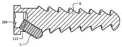
- FIG. 1is a schematic perspective view of an anchoring member in accordance with the present invention.
- FIG. 2 ais a schematic cross-sectional plan view of an anchoring member.
- FIG. 2 bis a top plan schematic view of the proximal end of the anchoring member.
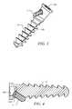
- FIG. 3is a schematic perspective view of an anchoring member with the locking member.
- FIG. 4is a schematic cross-sectional plan view of an anchoring member with the locking member
- FIG. 5is a perspective view of an anchoring member holding an object (plate).
- FIG. 6 ais a cross-sectional view of the shaft (Hex Key) of one embodiment of the first fastener F 1 .
- FIG. 6 bis a schematic perspective view of the distal end (ball end hex tool) of the first fastener F 1 .
- FIG. 6 cis a lateral view of the first fastener F 1 .
- FIG. 7is a schematic perspective view of a differential that can be used for the second fastener F 2 .
- FIG. 8 ais an enlarged perspective view of the distal end (ball end hex tool) of the first fastener F 1 .
- FIG. 8 bis an enlarged lateral view of the distal end (ball end hex tool) showing a 25 to 30 degree angle entry to the hex tool.
- FIG. 8 cis an example of oblique insertion.
- FIG. 8 dis a lateral view of the first fastener F 1 engaged within a hex screw.
- FIG. 9 ais a lateral view of a cortical-type locking member L.
- FIG. 9 bis a lateral view of a cancelous-type locking member L.
- FIG. 9 cis a lateral view of a headless-type locking member L.
- FIG. 10illustrates various angulation patterns of the interlocking anchor and locking members.
- FIG. 11illustrates one embodiment of a locking member within an anchoring member, in addition to the respective fastener having a corresponding angulation to the angulation of the locking member within the anchoring member.
- FIG. 12illustrates an exemplary embodiment of a fastener and its corresponding locking member within the anchoring member.
- Any mammalian bone, including human bone,may have the inventive systems, methods, and/or compositions of the present invention applied thereto.
- Examplesinclude long, short, flat, irregular, accessory, and sesamoid bones.
- Particular examplesinclude but are not limited to vertebrae, femur, humerus, radius, ulna, femur, tibia, fibula, clavicle, rib, metacarpals, metatarsals, phalanges, skull bones, sternum, scapulae, innominates, vertebrae, maxillae, sphenoid, carpus, tarsus, patella, interfrontal bone, epipteric bone, coronal ossicle, bregmatic ossicle, sagittal ossicle, lambdoid ossicle, and squame-parietal ossicle.
- the materials of the components of the present inventionmay be of any suitable kind.
- Materials of the anchor and locking memberare biocompatible, in certain embodiments.
- materialsinclude biomedical metallic materials, including stainless steel; alloys (Al, Co, Ni, Ta, W, V, etc.); cobalt-based alloys; or titanium and its alloys.
- Other examples of materialsinclude polymeric biomaterials, such as synthetic non-biodegradable polymers: polyethylene (high density polyethylene—HDPE—, ultrahigh molecular weight polyethylene—UHMWPE—), poly (ether ether ketone) or PEEK.
- Polymer matrix composite biomaterialsmay be employed and include fiber-reinforced composites (for example, carbon fiber or kevelar).
- the shape, diameter, length, and any associated angles of the anchor, locking member, and, by extrapolation, fastener(s) of the inventionmaybe of any kind, so long as the locking member is able to be positioned within the anchor at an angle to generate a V-shaped (or L-shaped, in a 90 degree configuration) configuration and so long as the corresponding fastener(s) can be inserted in the respective socket 104 in the head of anchor and/or locking member to apply torque for affixing them into bone.
- the anchoring system 100is generally comprised of an anchoring member A and a locking member L (see FIG. 3 )
- FIG. 1illustrates an anchoring member A in accordance with a certain embodiment.
- the anchoring member Agenerally has cancelous screws' features such as a 2-portion shaft comprising an optionally coarse, self-tapping thread 103 , designed to anchor in the softer medullary or cancelous bone, and topped by a smooth unthreaded portion 101 that allows it to act as a lag screw.
- the unthreaded upper portion 101presents an oblique aperture 102 having an angle (for example, of about)25° with respect to an axial plane of the anchoring member's shaft.
- the proximal end of the anchoring member Ahas a proximal end socket 104 such that it can be engaged by a fastener like a key, screwdriver, or wrench (see FIG.
- the proximal end of the anchoring member Ahas a Hex (hexagonal) type's proximal end socket 104 such that it can be engaged by a Hex tip fastener like a key or wrench (see FIG. 2 b ).
- fastenerrefers to a tool, such as a wrench, key, or screwdriver, that is employed to insert the corresponding anchor in the bone via the head of the anchor and/or to insert the corresponding locking member in the anchor via the socket 104 of the head of the locking member.
- the socket 104 of the head of the anchor or locking membermay be of any shape
- the embodiment presented herein wherein both heads are hexagonalis merely illustrative. That is, the shape of the socket 104 for insertion of the respective fastener in the anchor or locking member may be of any shape, including hexagonal, pentagonal, square, triangular, cross-shaped, plus sign-shaped, linear, star-shaped, and so forth, for example.
- the head of the locking memberis smaller than the head of the anchor, although in other embodiments the head of the locking member is the same size as the head of the anchor.
- the socket 104 of the proximal end of the anchor and the socket 104 of the proximal end of the locking memberare identical in shape and/or size, whereas in other specific embodiments the socket 104 of the proximal end of the anchor and the socket 104 of the proximal end of the locking member are not identical in shape and/or size.
- FIG. 2shows a cross-sectional view of the anchoring member ( FIG. 2 a ) and a top plan of the proximal end of the anchoring member ( FIG. 2 b ).
- the shape of the socket 104 for insertion of the respective fastener in the anchor or locking membermay be of any shape, including hexagonal, pentagonal, square, triangular, cross-shaped, plus sign-shaped, linear, star-shaped, and so forth, for example (see below); these may be referred to as slotted, Phillips, Pozidriv, torx, Hex key, Robertson, Tri-Wing, Torq-Set, or Spanner, for example.
- an exemplary hexagonal (Hex) socket in the head ( 104 ) of the anchoring memberbrings the following advantage: a ball end hex key (or wrench) can be used for angulated screwing and insertion, the contact surfaces of the screw are protected from external damage, the tool can be used with a headless screw, there are six contact surfaces between screw and driver, the socket's depth are less prone to stripping, and this room can be used for cannulation, for example.
- FIG. 3illustrates the anchoring system 100 comprising the anchoring member A and the locking member L.
- the angle ⁇ between the two membersis fixed and set up at 25 degrees in a certain embodiment.
- This angleallows using a standard hex second fastener F 2 (wherein F 1 fastener refers to the fastener for the anchor and F 2 fastener refers to the fastener for the locking member) equipped with an end ball hex end since it can be used with an angulation up to 30 degrees.
- the anglecan be set up to another value comprised between 1 to 90 degrees.
- the anglecan be 15-25 degrees. Beyond 30 degrees angulation, another embodiment of the second fastener F 2 with an inclinable hex tip end may be used (differential inner mechanism).
- FIG. 4is a schematic cross-sectional plan view of the anchoring system 100 .
- a headless locking member Lis engaged into a oblique aperture ( 111 ) within the exemplary hex-shaped socket ( 104 ) of the head of the anchoring member A.
- the surface of the inner wall of the aperturemay be threaded, smooth, or rough.
- One end of the apertureis at the proximal head of the anchor, and the opposite end is on one side of the anchor.
- FIG. 5is a perspective view of an anchoring member holding an exemplary object (plate) P.
- FIG. 6illustrates the first fastener F 1 with its Hex type tip ( 112 ).
- the fastenercomprises a head or tip that engages with the socket of the anchor to apply torque by rotating the tip, such as but not limited to a screwdriver, key or wrench.
- the tipis not limited to hex type.
- the second fastener F 2in certain aspects comprises a ball end hex type end to allow screwing of the locking member.
- the second fastener F 2can have the same features as the first fastener F 1 when used in a particular embodiment e.g. with an angle ⁇ between the two members equal at 25 degrees, or inferior at 30 degrees at the maximum, in accordance with the working angle (25 to 30 degrees) of such ball end hex tip.
- the second fastener F 2being thinner than the first fastener F 1 in order to be able to slid within the inner socket 104 of the first fastener F 1 , in particular embodiments.
- an angle ⁇higher than the angle ⁇ , e.g. superior at 30 degrees between the two members A and L, is set up.
- the second fastener F 2presents an inclinable tip able to match the angle ⁇ and is equipped with an inner mechanism applying the torque in accordance with an oblique transmission of the rotating motion imparted to the handle of the fastener.
- Such mechanismcan be but is not limited to a differential, a screw gear, or a set of gears.
- FIG. 7illustrates the principle of such mechanism and shows a schematic conceptual view of a differential.
- Such a fastenercan be rotated manually or by an electric or other motor.
- FIG. 8 ais an enlarged perspective view of the distal end (ball end hex tool) of the fastener.
- the concept by which ball ends slide into a screw headis known as funnel insertion. Basically, it means that the sides of the ball end direct (funnel) it into place. This allows fast funnel entry, eliminates wasted time even in blind applications, and the full depth engagement reduces “stripping” problems.
- FIG. 8 bis an enlarged lateral view of the distal end (ball end hex tool) showing a 25 to 30 degree angle entry to hex.
- neck sizedecreases, and strength also decreases.
- increasing the strength of a ball-end toolrequires a corresponding increase in neck size and decrease in maximum allowable angle.
- Designing the perfect ball-end toolmeans choosing the ideal balance between strength and allowable angle.
- FIG. 8 cis an example of oblique insertion.
- FIG. 8 dis a lateral view of the first fastener F 1 engaged within a hex screw.
- FIG. 9illustrates the three possible designs of the locking member L.
- the locking member Lis thinner than the anchoring member A so that it can be slid through the oblique aperture and positioned within the empty room of the hexagonal socket of the anchoring member. Its length can be smaller, equal or bigger than the anchoring member. Its proximal end can be equipped with a head ( 105 ) or be wide-mouthed ( 106 ) to block within the anchoring member's head, or be headless ( 107 ). Whatever the type of the locking member L can be (headed 105 , wide-mouthed 106 or headless 107 ), the socket has a hex type shape, in certain embodiments.
- the locking membercan be a cortical type screw ( FIG. 9 a ) with a fine thread ( 108 ) all along its shaft and therefore screwed into an oblique threaded canal within the anchoring member's head, or a cancelous type screw ( FIG. 9 b ) with a coarser thread ( 109 ), designed to anchor the bone and a smooth, unthreaded portion ( 110 ), designed to slid within an oblique unthreaded canal within the anchoring member's head.
- the locking member Lcan just act as an anti-rotational device and prevent the unscrewing of the anchoring member A in the cortical type design, or be both a blocking system as described above and an additional fastening device intended to secure and reinforce the grip within the medullary bone in the cancelous type design.
- the adjunction of a second divergent memberadvantageously increases both the grip and the purchase within the bone, especially in cancelous and/or osteoporotic bone and therefore opposes to pull-out and secures the fixation of any object to the bone.
- FIG. 10illustrates various angulation patterns of the interlocking anchor and locking members.
- the proximal end of the anchoring memberrequires a cavity at its socket to allow the fastener access to the locking member.
- FIG. 11illustrates one embodiment of a locking member within an anchoring member, in addition to the respective fastener having a corresponding angulation to the angulation of the locking member within the anchoring member.
- the proximal end of the anchoring memberhas a cavity that allows insertion of the fastener for the locking member.
- FIG. 12illustrates an exemplary embodiment of a fastener and its corresponding locking member within the anchoring member.
- the proximal end of the anchoring membercomprises a cavity that allows insertion of the fastener for the locking member.
- the anchor and locking memberare coated with antibiotic or other medicine useful upon implantation of an implant on and/or in a bone.
- the surface of the anchor and/or locking memberis rough for a better grip within the bone.
- kits of the present inventionmay include a means for containing the invention component(s) in close confinement for commercial sale.
- Such containersmay include injection or blow molded plastic containers into which the components are retained, for example.
- the kitmay comprise the anchor, locking member, and/or fastener(s). In some cases, all components are sold separate, whereas in other cases all or a subset of components are sold together. Irrespective of the number and/or type of containers, the kits of the invention may also comprise, and/or be packaged with, an instrument other than a fastener(s) of the invention for assisting with placing the anchor/locking member within the body of an animal.
- a variety of anchors, locking members, and/or fastenersmay be provided in a kit.
- a variety of lengths, diameters, socket shapes, and/or angles of the corresponding anchors, locking members, and/or fastener(s)may be provided in a kit.
Landscapes
- Health & Medical Sciences (AREA)
- Orthopedic Medicine & Surgery (AREA)
- Life Sciences & Earth Sciences (AREA)
- Surgery (AREA)
- Engineering & Computer Science (AREA)
- Heart & Thoracic Surgery (AREA)
- General Health & Medical Sciences (AREA)
- Biomedical Technology (AREA)
- Veterinary Medicine (AREA)
- Medical Informatics (AREA)
- Molecular Biology (AREA)
- Animal Behavior & Ethology (AREA)
- Nuclear Medicine, Radiotherapy & Molecular Imaging (AREA)
- Public Health (AREA)
- Neurology (AREA)
- General Engineering & Computer Science (AREA)
- Mechanical Engineering (AREA)
- Surgical Instruments (AREA)
- Prostheses (AREA)
Abstract
Description


Claims (43)
Priority Applications (1)
| Application Number | Priority Date | Filing Date | Title |
|---|---|---|---|
| US12/934,196US9084646B2 (en) | 2008-03-26 | 2009-03-26 | Universal anchor for attaching objects to bone tissue |
Applications Claiming Priority (3)
| Application Number | Priority Date | Filing Date | Title |
|---|---|---|---|
| US3946408P | 2008-03-26 | 2008-03-26 | |
| US12/934,196US9084646B2 (en) | 2008-03-26 | 2009-03-26 | Universal anchor for attaching objects to bone tissue |
| PCT/US2009/038376WO2009120852A2 (en) | 2008-03-26 | 2009-03-26 | Universal anchor for attaching objects to bone tissue |
Related Parent Applications (1)
| Application Number | Title | Priority Date | Filing Date |
|---|---|---|---|
| PCT/US2009/038376A-371-Of-InternationalWO2009120852A2 (en) | 2008-03-26 | 2009-03-26 | Universal anchor for attaching objects to bone tissue |
Related Child Applications (1)
| Application Number | Title | Priority Date | Filing Date |
|---|---|---|---|
| US14/740,904DivisionUS10045804B2 (en) | 2008-03-26 | 2015-06-16 | Universal anchor for attaching objects to bone tissue |
Publications (2)
| Publication Number | Publication Date |
|---|---|
| US20110022066A1 US20110022066A1 (en) | 2011-01-27 |
| US9084646B2true US9084646B2 (en) | 2015-07-21 |
Family
ID=41114711
Family Applications (2)
| Application Number | Title | Priority Date | Filing Date |
|---|---|---|---|
| US12/934,196Expired - Fee RelatedUS9084646B2 (en) | 2008-03-26 | 2009-03-26 | Universal anchor for attaching objects to bone tissue |
| US14/740,904Active2029-05-01US10045804B2 (en) | 2008-03-26 | 2015-06-16 | Universal anchor for attaching objects to bone tissue |
Family Applications After (1)
| Application Number | Title | Priority Date | Filing Date |
|---|---|---|---|
| US14/740,904Active2029-05-01US10045804B2 (en) | 2008-03-26 | 2015-06-16 | Universal anchor for attaching objects to bone tissue |
Country Status (9)
| Country | Link |
|---|---|
| US (2) | US9084646B2 (en) |
| EP (2) | EP3108834B1 (en) |
| JP (2) | JP5788787B2 (en) |
| KR (1) | KR101602153B1 (en) |
| CN (2) | CN104068925B (en) |
| BR (1) | BRPI0911290B8 (en) |
| CA (1) | CA2719699C (en) |
| CO (1) | CO6331410A2 (en) |
| WO (1) | WO2009120852A2 (en) |
Cited By (9)
| Publication number | Priority date | Publication date | Assignee | Title |
|---|---|---|---|---|
| US20160128732A1 (en)* | 2014-11-11 | 2016-05-12 | Intrepid Orthopedics | Supplemental Fixation Screw |
| US20170143470A1 (en)* | 2014-05-09 | 2017-05-25 | Abanza Tecnomed, S.L. | Device for trapping the end of at least one fascicle of soft material in a bone tunnel |
| US10045804B2 (en) | 2008-03-26 | 2018-08-14 | Depuy Synthes, Inc. | Universal anchor for attaching objects to bone tissue |
| US10376269B2 (en) | 2014-08-28 | 2019-08-13 | Cochlear Limited | Bone fixture for medical prosthesis |
| US20200400196A1 (en)* | 2018-02-28 | 2020-12-24 | Evollution Ip Holdings, Inc. | Off-angle screw engagement |
| US11344348B2 (en)* | 2019-01-02 | 2022-05-31 | Orthofix Us Llc | Bone fixation system and methods of use |
| US20220192720A1 (en)* | 2020-12-18 | 2022-06-23 | DePuy Synthes Products, Inc. | Screw-in-screw bone fixation system |
| US12185997B2 (en) | 2019-08-14 | 2025-01-07 | K2M, Inc. | Pedicle fixation system |
| USD1092739S1 (en)* | 2023-03-03 | 2025-09-09 | Abanza Tecnomed, S.L. | Medical implant |
Families Citing this family (37)
| Publication number | Priority date | Publication date | Assignee | Title |
|---|---|---|---|---|
| CN102046111A (en) | 2008-06-05 | 2011-05-04 | 斯恩蒂斯有限公司 | Articulating disc implant |
| US8882838B2 (en) | 2008-06-05 | 2014-11-11 | DePuy Synthes Products, LLC | Articulating disc implant |
| US8328806B2 (en)* | 2008-06-24 | 2012-12-11 | Extremity Medical, Llc | Fixation system, an intramedullary fixation assembly and method of use |
| US9044282B2 (en)* | 2008-06-24 | 2015-06-02 | Extremity Medical Llc | Intraosseous intramedullary fixation assembly and method of use |
| US8343199B2 (en)* | 2008-06-24 | 2013-01-01 | Extremity Medical, Llc | Intramedullary fixation screw, a fixation system, and method of fixation of the subtalar joint |
| US8313487B2 (en)* | 2008-06-24 | 2012-11-20 | Extremity Medical Llc | Fixation system, an intramedullary fixation assembly and method of use |
| US9017329B2 (en)* | 2008-06-24 | 2015-04-28 | Extremity Medical, Llc | Intramedullary fixation assembly and method of use |
| US9289220B2 (en) | 2008-06-24 | 2016-03-22 | Extremity Medical Llc | Intramedullary fixation assembly and method of use |
| US20110230884A1 (en)* | 2008-06-24 | 2011-09-22 | Adam Mantzaris | Hybrid intramedullary fixation assembly and method of use |
| US8303589B2 (en) | 2008-06-24 | 2012-11-06 | Extremity Medical Llc | Fixation system, an intramedullary fixation assembly and method of use |
| US9060808B2 (en) | 2008-12-05 | 2015-06-23 | DePuy Synthes Products, Inc. | Anchor-in-anchor system for use in bone fixation |
| JP5759900B2 (en)* | 2008-12-05 | 2015-08-05 | ジンテス ゲゼルシャフト ミット ベシュレンクテル ハフツング | Anchor-in-anchor system for use in bone fixation |
| US20110230920A1 (en)* | 2010-03-19 | 2011-09-22 | K2M, Inc. | Spinal fixation apparatus and methods |
| CA2797790A1 (en)* | 2010-05-13 | 2011-11-17 | Synthes Usa, Llc | Bone screw assembly and instruments for implantation of the same |
| AU2010354781B2 (en)* | 2010-06-09 | 2015-03-26 | Synthes Gmbh | Anchor-in-anchor system for use in bone fixation |
| EP2455014B1 (en)* | 2010-11-17 | 2015-08-12 | Hyprevention | Implantable device for preventive or interventive treatment of femur fractures, associated ancillary device |
| CH705356A2 (en)* | 2011-08-11 | 2013-02-15 | Regenhu Ag | Body with a basic structure made from bone substitute material and methods of making. |
| CN102835998A (en)* | 2012-08-17 | 2012-12-26 | 苏州瑞华医院有限公司 | Novel internally fixing and locking bone fracture plate for curing of humerus collum chirurgicum fractures |
| CA2882601C (en) | 2012-08-22 | 2020-10-27 | Andreas Appenzeller | Anchor-in-anchor system |
| US20150005856A1 (en)* | 2013-06-27 | 2015-01-01 | Boston Scientific Neuromodulation Corporation | Lead anchors and systems and methods using the lead anchors |
| US9855132B2 (en)* | 2015-01-30 | 2018-01-02 | Arthrex, Inc. | Ligament fixation device and method |
| CN104688285B (en)* | 2015-03-27 | 2017-09-29 | 王谦 | Shoulder joint sutures self-locking structure |
| GR20150100144A (en)* | 2015-03-30 | 2016-10-20 | Γεωργιος Κωνσταντινου Κωστακης | Dental implant with improved stability and osseointegration features |
| US9636498B2 (en) | 2015-08-03 | 2017-05-02 | Boston Scientific Neuromodulation Corporation | Lead anchor with a wedge and systems using the lead anchor |
| US20170105820A1 (en)* | 2015-10-20 | 2017-04-20 | Implant Direct Sybron International Llc | Screw and driver tool for dental procedures |
| WO2017151438A1 (en) | 2016-02-29 | 2017-09-08 | Boston Scientific Neuromodulation Corporation | Lead anchor for an electrical stimulation system |
| WO2017201058A1 (en) | 2016-05-17 | 2017-11-23 | Boston Scientific Neuromodulation Corporation | Systems and methods for anchoring a lead for neurostimulation of a target anatomy |
| CN105997218A (en)* | 2016-06-29 | 2016-10-12 | 江苏艾迪尔医疗科技股份有限公司 | Humeral inverted intramedullary nail |
| ES2676437B1 (en)* | 2017-01-19 | 2019-04-29 | Delgado Oscar Ruesga | Two-phase precision guide and its method for fixing a tripod with a short dental implant function in a low-lying maxillary bone. |
| US10709886B2 (en) | 2017-02-28 | 2020-07-14 | Boston Scientific Neuromodulation Corporation | Electrical stimulation leads and systems with elongate anchoring elements and methods of making and using |
| US10835739B2 (en) | 2017-03-24 | 2020-11-17 | Boston Scientific Neuromodulation Corporation | Electrical stimulation leads and systems with elongate anchoring elements and methods of making and using |
| WO2018187770A1 (en) | 2017-04-06 | 2018-10-11 | Extremity Medical, Llc | Orthopedic plate with modular peg and compression screw |
| US10857351B2 (en) | 2017-04-28 | 2020-12-08 | Boston Scientific Neuromodulation Corporation | Lead anchors for electrical stimulation leads and systems and methods of making and using |
| EP4009888B1 (en)* | 2019-10-09 | 2023-07-19 | Kaj Klaue | Bone nail |
| CN113662647A (en)* | 2020-05-15 | 2021-11-19 | 北京中安泰华科技有限公司 | Clavicle automatic pressurizing intramedullary nail with lock |
| US12327486B1 (en)* | 2021-03-19 | 2025-06-10 | HIMM Holdings | Modular mammalian infant head model for oral examination training |
| CN114305636A (en)* | 2022-01-10 | 2022-04-12 | 航天中心医院 | Patella fracture nail cable locking device |
Citations (83)
| Publication number | Priority date | Publication date | Assignee | Title |
|---|---|---|---|---|
| US928997A (en) | 1908-07-07 | 1909-07-27 | Emanuel Mueller | Lock-screw. |
| US3474537A (en) | 1965-10-19 | 1969-10-28 | Robert W Christensen | Dental prosthetic appliance |
| JPS54118566A (en) | 1978-03-06 | 1979-09-14 | Nippon Electric Co | Method of producing laminated ceramic capacitor |
| US4338835A (en) | 1980-01-24 | 1982-07-13 | Leon Simons | Recessed head fastener and driver therefor |
| US4759766A (en) | 1984-09-04 | 1988-07-26 | Humboldt-Universitaet Zu Berlin | Intervertebral disc endoprosthesis |
| EP0330328A1 (en) | 1988-02-04 | 1989-08-30 | Pfizer Hospital Products Group, Inc. | Anterior cruciate ligament prosthesis |
| US5038978A (en) | 1989-11-13 | 1991-08-13 | B&G Plastics, Inc. | Hanger and display support combined therewith |
| US5140877A (en)* | 1990-12-14 | 1992-08-25 | John Sloan | Hexagonal wrench |
| US5207529A (en) | 1992-06-29 | 1993-05-04 | General Motors Corporation | Fastening device |
| US5251521A (en) | 1992-01-31 | 1993-10-12 | Bondhus Corporation | TORX-compatible elliptical driver |
| US5425767A (en) | 1992-11-02 | 1995-06-20 | Sulzer Medizinaltechnik Ag | Anchor for an artificial ligament |
| US5443469A (en) | 1994-05-02 | 1995-08-22 | Smith; Aubrey L. | Intramedullary reaming tissue protection guard |
| US5505731A (en) | 1993-09-01 | 1996-04-09 | Tornier Sa | Screw for lumbar-sacral fixator |
| US5797918A (en)* | 1991-12-13 | 1998-08-25 | David A. McGuire | Flexible surgical screwdriver and methods of arthroscopic ligament reconstruction |
| US5899941A (en) | 1997-12-09 | 1999-05-04 | Chubu Bearing Kabushiki Kaisha | Artificial intervertebral disk |
| WO1999047061A1 (en) | 1998-03-16 | 1999-09-23 | Scandimed International Ab | Instrument for repositioning and fixation of wrist fractures |
| US5984681A (en)* | 1997-09-02 | 1999-11-16 | Huang; Barney K. | Dental implant and method of implanting |
| US5993463A (en) | 1997-05-15 | 1999-11-30 | Regents Of The University Of Minnesota | Remote actuation of trajectory guide |
| US6013078A (en) | 1998-08-19 | 2000-01-11 | Lin; Chin | Securing device for bone fastener |
| WO2000038586A1 (en) | 1998-12-23 | 2000-07-06 | Nenad Sesic | Axial intramedullary screw for the osteosynthesis of long bones |
| US6113637A (en) | 1998-10-22 | 2000-09-05 | Sofamor Danek Holdings, Inc. | Artificial intervertebral joint permitting translational and rotational motion |
| WO2000069352A1 (en) | 1999-05-18 | 2000-11-23 | Merete Management Gmbh | Screw for fixing bone fractures |
| US6168598B1 (en) | 1997-06-02 | 2001-01-02 | Jeannette Martello | Soft tissue securing anchor |
| US6270499B1 (en) | 1997-10-20 | 2001-08-07 | Synthes (U.S.A.) | Bone fixation device |
| JP2001252283A (en) | 2000-03-10 | 2001-09-18 | Robert Reed Shokai Co Ltd | Rod fixing device |
| US20020128712A1 (en)* | 2001-03-09 | 2002-09-12 | Michelson Gary K. | Expansion constraining member adapted for use with an expandable interbody spinal fusion implant |
| US6467919B1 (en) | 2001-11-02 | 2002-10-22 | Gentex Corporation | Mirror with split ball mount and hold-open device |
| JP2003518408A (en) | 1999-12-23 | 2003-06-10 | デュプュイ フランス | Shoulder prosthesis assembly |
| US20030135216A1 (en) | 2000-05-25 | 2003-07-17 | Sevrain Lionel C. | Anchoring system for fixing objects to bones |
| US20030171753A1 (en) | 2001-10-25 | 2003-09-11 | Corin Limited | Surgical implant |
| US20030199876A1 (en) | 2000-04-19 | 2003-10-23 | Synthes (Usa) | Bone fixation assembly |
| US6695844B2 (en) | 1996-03-13 | 2004-02-24 | Orthopedic Designs, Inc. | Surgical fastener assembly |
| US20040111161A1 (en) | 2002-12-10 | 2004-06-10 | Trieu Hai H. | System and method for blocking and/or retaining a prosthetic spinal implant |
| US20050018931A1 (en) | 2003-07-26 | 2005-01-27 | Shrader Arthur Joseph | Method and apparatus for hanging a resealable bag |
| US20050033438A1 (en) | 2003-07-08 | 2005-02-10 | Robert Schultz | Intervertebral implant |
| US20050107791A1 (en)* | 2003-11-14 | 2005-05-19 | Manderson Easton L. | Intramedullary locked compression screw for stabiliziation and union of complex ankle and subtalar deformities |
| CN1665459A (en) | 2002-09-02 | 2005-09-07 | 马斯医药技术股份公司 | Intervertebral implant comprising a three-part articulation |
| WO2006016384A1 (en) | 2004-08-12 | 2006-02-16 | Sintea Biotech S.P.A. | Disc prosthesis |
| US20060052787A1 (en) | 2004-08-18 | 2006-03-09 | Paul Re | Method and apparatus for reconstructing a ligament |
| US20060064095A1 (en) | 2003-03-07 | 2006-03-23 | Peter Senn | Locking screw for an intramedullary nail |
| EP1658816A1 (en) | 2004-11-19 | 2006-05-24 | Gian Luca Rovesti | Surgical screw with spontaneous loosening preventive blocking system |
| US20060116676A1 (en) | 2002-12-17 | 2006-06-01 | Thomas Gradel | Device comprising anterior plate for vertebral column support |
| US7094242B2 (en) | 2001-10-31 | 2006-08-22 | K2M, Inc. | Polyaxial drill guide |
| US20060189991A1 (en)* | 2005-01-11 | 2006-08-24 | Bickley Barry T | Graft anchor |
| WO2006119092A2 (en) | 2005-05-02 | 2006-11-09 | Seaspine, Inc. | Motion restoring intervertebral device |
| US7198643B2 (en) | 2003-03-06 | 2007-04-03 | Spinecore, Inc. | Cervical disc replacement |
| WO2007048038A2 (en) | 2005-10-21 | 2007-04-26 | Acumed Llc | Orthopedic rod with locking aperture |
| EP1779794A1 (en) | 2005-10-31 | 2007-05-02 | DePuy Products, Inc. | Orthopaedic nail with oblique openings |
| US20070112354A1 (en) | 2003-05-27 | 2007-05-17 | Pentax Corporation | Surgical instruments |
| US20070191952A1 (en) | 2006-02-16 | 2007-08-16 | Amedica Corporation | Spinal implant with elliptical articulatory interface |
| WO2007098288A2 (en) | 2006-02-27 | 2007-08-30 | Synthes (U.S.A.) | Intervertebral implant with fixation geometry |
| US20070213729A1 (en) | 2006-03-08 | 2007-09-13 | Sdgi Holdings, Inc. | Flexible bone plates and methods for dynamic spinal stabilization |
| CN101102730A (en) | 2004-11-26 | 2008-01-09 | 脊骨分离有限公司 | Intervertebral implant |
| US20080140130A1 (en) | 2004-01-26 | 2008-06-12 | Chan Jason S | Highly-versatile variable-angle bone plate system |
| US20080221624A1 (en) | 2005-10-17 | 2008-09-11 | Gooch Hubert L | Systems and Methods for the Medical Treatment of Structural Tissue |
| US20080221623A1 (en) | 2005-10-17 | 2008-09-11 | Gooch Hubert L | Systems and Methods for the Medical Treatment of Structural Tissue |
| US20080243253A1 (en) | 2005-05-03 | 2008-10-02 | Spineart Sa | Intervertebral Disc Prosthesis |
| US7524326B2 (en) | 2003-09-12 | 2009-04-28 | Signus Medizintechnik Gmbh | Bone screw |
| US20090120852A1 (en) | 2003-05-19 | 2009-05-14 | Ellsworth James R | Method and apparatus for separating fluid components |
| WO2009092907A2 (en) | 2007-11-05 | 2009-07-30 | H.P.I | Intervertebral disc prosthesis |
| WO2009149371A1 (en) | 2008-06-05 | 2009-12-10 | Synthes Usa, Llc | Articulating disc implant |
| US20090326545A1 (en) | 2008-06-26 | 2009-12-31 | Amedica Corporation | Systems and methods for inserting a bone anchor without a pilot hole |
| US20100121324A1 (en) | 2008-06-24 | 2010-05-13 | Jeff Tyber | Fixation system, an intramedullary fixation assembly and method of use |
| US20100121325A1 (en) | 2008-06-24 | 2010-05-13 | Jeff Tyber | Hybrid intramedullary fixation assembly and method of use |
| US20100145397A1 (en) | 2008-12-05 | 2010-06-10 | Tom Overes | Anchor-in-anchor system for use in bone fixation |
| US20100160924A1 (en) | 2008-12-23 | 2010-06-24 | Howmedica Osteonics Corp. | Drill guide with angle verification |
| US20100167240A1 (en) | 2007-03-23 | 2010-07-01 | Biomain Ab | Screwdriver and screw member adapted therefore |
| US20100256639A1 (en) | 2008-06-24 | 2010-10-07 | Jeff Tyber | Fixation system, an intramedullary fixation assembly and method of use |
| US20100256638A1 (en) | 2008-06-24 | 2010-10-07 | Jeff Tyber | Intraosseous intramedullary fixation assembly and method of use |
| US20100312280A1 (en) | 2008-12-05 | 2010-12-09 | Synthes Usa, Llc | Anchor-in-anchor system for use in bone fixation |
| US20100324556A1 (en) | 2008-06-24 | 2010-12-23 | Jeff Tyber | Fixation system, an intramedullary fixation assembly and method of use |
| US20110022066A1 (en) | 2008-03-26 | 2011-01-27 | Synthes Usa, Llc | Universal anchor for attaching objects to bone tissue |
| US20110118739A1 (en) | 2008-06-24 | 2011-05-19 | Jeff Tyber | Intramedullary fixation assembly and method of use |
| US20110125153A1 (en) | 2008-06-24 | 2011-05-26 | Jeff Tyber | Intramedullary fixation assembly and method of use |
| US20110137312A1 (en) | 2008-06-13 | 2011-06-09 | Orthofix S.R.L. | Intermarrow nail to be inserted into a fractured long bone |
| US20110160729A1 (en) | 2009-07-01 | 2011-06-30 | Tom Overes | Intramedullary Nail and Protruding Screw Locking Mechanism |
| US7981114B2 (en) | 2003-06-20 | 2011-07-19 | Stryker Trauma Gmbh | Drilling tool guide wire alignment device |
| US20110184470A1 (en) | 2008-08-07 | 2011-07-28 | K2M, Inc. | Bone screw assembly |
| US20110213367A1 (en) | 2008-06-24 | 2011-09-01 | Jeff Tyber | Intramedullary fixation screw, a fixation system, and method of fixation of the subtalar joint |
| US20110230920A1 (en) | 2010-03-19 | 2011-09-22 | K2M, Inc. | Spinal fixation apparatus and methods |
| US20110230884A1 (en) | 2008-06-24 | 2011-09-22 | Adam Mantzaris | Hybrid intramedullary fixation assembly and method of use |
| US20110282398A1 (en) | 2010-05-13 | 2011-11-17 | Tom Overes | Bone Screw Assembly and Instruments for Implantation of the Same |
| WO2011155931A1 (en) | 2010-06-09 | 2011-12-15 | Synthes Usa, Llc | Anchor-in-anchor system for use in bone fixation |
Family Cites Families (43)
| Publication number | Priority date | Publication date | Assignee | Title |
|---|---|---|---|---|
| US1518119A (en)* | 1922-08-05 | 1924-12-02 | Aseptic Service Company | Locked fastening |
| GB303708A (en)* | 1928-04-27 | 1929-01-10 | Frank Harold Clause | Improvements in or relating to means for securing in position screws, nails or the like |
| US3295579A (en)* | 1965-03-08 | 1967-01-03 | Allis Chalmers Mfg Co | Lock bolt |
| US3579831A (en)* | 1969-03-05 | 1971-05-25 | Irving J Stevens | Bone implant |
| JPS54118566U (en)* | 1978-02-07 | 1979-08-20 | ||
| JPS6114484Y2 (en)* | 1981-02-12 | 1986-05-07 | ||
| DE3124059A1 (en) | 1981-06-18 | 1983-01-05 | Mecron Medizinische Produkte Gmbh, 1000 Berlin | Nail for fixing fractures of the femur |
| DE3312959A1 (en)* | 1983-04-11 | 1984-10-11 | Erich 8217 Grassau Stabenau | Securing device for a wood screw |
| US4754749A (en)* | 1986-04-29 | 1988-07-05 | Tsou Paul M | Surgical screw with counter-rotation prevention means |
| US5370662A (en) | 1993-06-23 | 1994-12-06 | Kevin R. Stone | Suture anchor assembly |
| FR2718014A1 (en) | 1994-04-05 | 1995-10-06 | Chagneau Francis | Anchor screw assembly for joint prosthesis cup implant |
| GB9411693D0 (en) | 1994-06-10 | 1994-08-03 | Matthews Michael G | Surgical intramedullary nail for stabilisation of condylar and supracondylar fractures |
| AU1997797A (en) | 1996-05-31 | 1997-12-04 | Acromed Corporation | An apparatus comprising a plate and a fastener for connecting the plate to a bone portion |
| US6221074B1 (en) | 1999-06-10 | 2001-04-24 | Orthodyne, Inc. | Femoral intramedullary rod system |
| US6409730B1 (en) | 2000-05-31 | 2002-06-25 | Synthes (Usa) | Humeral spiral blade |
| US6629998B1 (en) | 2000-08-23 | 2003-10-07 | Chih-I Lin | Intervertebral retrieval device |
| US6443954B1 (en) | 2001-04-24 | 2002-09-03 | Dale G. Bramlet | Femoral nail intramedullary system |
| US6524314B1 (en) | 2001-08-24 | 2003-02-25 | John C. Dean | Interlocking intramedullary nail |
| US6835197B2 (en) | 2001-10-17 | 2004-12-28 | Christoph Andreas Roth | Bone fixation system |
| US20040019353A1 (en) | 2002-02-01 | 2004-01-29 | Freid James M. | Spinal plate system for stabilizing a portion of a spine |
| AR038680A1 (en) | 2002-02-19 | 2005-01-26 | Synthes Ag | INTERVERTEBRAL IMPLANT |
| US6681662B2 (en) | 2002-03-01 | 2004-01-27 | Bondhus Corporation | Tool with fastener engaging member |
| CN1309352C (en) | 2002-07-22 | 2007-04-11 | 精密医疗责任有限公司 | Bone fusion system |
| US20060229729A1 (en) | 2003-08-05 | 2006-10-12 | Gordon Charles R | Expandable intervertebral implant for use with instrument |
| DE20321551U1 (en) | 2003-08-26 | 2007-12-27 | Synthes Gmbh | bone plate |
| US20050055024A1 (en) | 2003-09-08 | 2005-03-10 | James Anthony H. | Orthopaedic implant and screw assembly |
| US7637928B2 (en) | 2004-01-26 | 2009-12-29 | Synthes Usa, Llc | Variable angle locked bone fixation system |
| ES2306976T3 (en) | 2004-09-27 | 2008-11-16 | Orthofix S.R.L. | INTRAMEDULAR SCREW FOR THE TREATMENT OF FEMUR PROXIMAL FRACTURES. |
| US20070156145A1 (en) | 2005-12-30 | 2007-07-05 | Kentomia, Llc | Therapeutic constructions, spinal plates, cervical plates, hooks and screws |
| US20080033438A1 (en)* | 2006-08-04 | 2008-02-07 | Roy Frizzell | Cervical Saddle Plate |
| US8303590B2 (en) | 2007-01-26 | 2012-11-06 | Ebi, Llc | Lockable intramedullary fixation device |
| US20080249569A1 (en) | 2007-04-03 | 2008-10-09 | Warsaw Orthopedic, Inc. | Implant Face Plates |
| FR2916624B1 (en) | 2007-05-29 | 2009-08-21 | Small Bone Innovations Interna | BONE SCREW, IN PARTICULAR OSTEOSYNTHESIS |
| AU2008318657A1 (en) | 2007-10-30 | 2009-05-07 | Synthes Gmbh | Variable angle locked bone plate |
| US8882838B2 (en) | 2008-06-05 | 2014-11-11 | DePuy Synthes Products, LLC | Articulating disc implant |
| US8328872B2 (en) | 2008-09-02 | 2012-12-11 | Globus Medical, Inc. | Intervertebral fusion implant |
| US8231625B2 (en) | 2008-09-03 | 2012-07-31 | The Cleveland Clinic Foundation | Modular bone fixation device for treatment of fractures and related methods |
| CN101507652A (en) | 2009-03-20 | 2009-08-19 | 周志海 | Knee joint approach intramedullary nail |
| US10335214B2 (en) | 2009-04-24 | 2019-07-02 | DePuy Synthes Products, Inc. | Multiplexed screws |
| US8758346B2 (en) | 2009-09-14 | 2014-06-24 | DePuy Synthes Products, LLC | Variable angle compression plate |
| US8486116B2 (en) | 2010-01-08 | 2013-07-16 | Biomet Manufacturing Ring Corporation | Variable angle locking screw |
| EP2460484A1 (en) | 2010-12-01 | 2012-06-06 | FACET-LINK Inc. | Variable angle bone screw fixation assembly |
| EP2667798B1 (en) | 2011-01-28 | 2015-07-29 | Synthes GmbH | Reamer guide systems |
- 2009
- 2009-03-26CNCN201410086633.9Apatent/CN104068925B/ennot_activeExpired - Fee Related
- 2009-03-26CNCN200980118021.0Apatent/CN102046105B/ennot_activeExpired - Fee Related
- 2009-03-26EPEP16001477.5Apatent/EP3108834B1/enactiveActive
- 2009-03-26USUS12/934,196patent/US9084646B2/ennot_activeExpired - Fee Related
- 2009-03-26JPJP2011502049Apatent/JP5788787B2/ennot_activeExpired - Fee Related
- 2009-03-26CACA2719699Apatent/CA2719699C/enactiveActive
- 2009-03-26WOPCT/US2009/038376patent/WO2009120852A2/enactiveApplication Filing
- 2009-03-26BRBRPI0911290Apatent/BRPI0911290B8/ennot_activeIP Right Cessation
- 2009-03-26EPEP09724639.1Apatent/EP2285299B1/ennot_activeNot-in-force
- 2009-03-26KRKR1020107023629Apatent/KR101602153B1/ennot_activeExpired - Fee Related
- 2010
- 2010-10-26COCO10132564Apatent/CO6331410A2/enactiveIP Right Grant
- 2015
- 2015-06-16USUS14/740,904patent/US10045804B2/enactiveActive
- 2015-07-30JPJP2015150310Apatent/JP6258269B2/ennot_activeExpired - Fee Related
Patent Citations (97)
| Publication number | Priority date | Publication date | Assignee | Title |
|---|---|---|---|---|
| US928997A (en) | 1908-07-07 | 1909-07-27 | Emanuel Mueller | Lock-screw. |
| US3474537A (en) | 1965-10-19 | 1969-10-28 | Robert W Christensen | Dental prosthetic appliance |
| JPS54118566A (en) | 1978-03-06 | 1979-09-14 | Nippon Electric Co | Method of producing laminated ceramic capacitor |
| US4338835A (en) | 1980-01-24 | 1982-07-13 | Leon Simons | Recessed head fastener and driver therefor |
| US4759766A (en) | 1984-09-04 | 1988-07-26 | Humboldt-Universitaet Zu Berlin | Intervertebral disc endoprosthesis |
| EP0330328A1 (en) | 1988-02-04 | 1989-08-30 | Pfizer Hospital Products Group, Inc. | Anterior cruciate ligament prosthesis |
| US5038978A (en) | 1989-11-13 | 1991-08-13 | B&G Plastics, Inc. | Hanger and display support combined therewith |
| US5140877A (en)* | 1990-12-14 | 1992-08-25 | John Sloan | Hexagonal wrench |
| US5797918A (en)* | 1991-12-13 | 1998-08-25 | David A. McGuire | Flexible surgical screwdriver and methods of arthroscopic ligament reconstruction |
| US5251521A (en) | 1992-01-31 | 1993-10-12 | Bondhus Corporation | TORX-compatible elliptical driver |
| US5207529A (en) | 1992-06-29 | 1993-05-04 | General Motors Corporation | Fastening device |
| US5425767A (en) | 1992-11-02 | 1995-06-20 | Sulzer Medizinaltechnik Ag | Anchor for an artificial ligament |
| US5505731A (en) | 1993-09-01 | 1996-04-09 | Tornier Sa | Screw for lumbar-sacral fixator |
| US5443469A (en) | 1994-05-02 | 1995-08-22 | Smith; Aubrey L. | Intramedullary reaming tissue protection guard |
| US6695844B2 (en) | 1996-03-13 | 2004-02-24 | Orthopedic Designs, Inc. | Surgical fastener assembly |
| US5993463A (en) | 1997-05-15 | 1999-11-30 | Regents Of The University Of Minnesota | Remote actuation of trajectory guide |
| US6168598B1 (en) | 1997-06-02 | 2001-01-02 | Jeannette Martello | Soft tissue securing anchor |
| US6648892B2 (en) | 1997-06-02 | 2003-11-18 | Jeannette Martello | Soft tissue securing anchor |
| US7163540B2 (en) | 1997-06-02 | 2007-01-16 | Jeannette Martello | Soft tissue securing anchor |
| US5984681A (en)* | 1997-09-02 | 1999-11-16 | Huang; Barney K. | Dental implant and method of implanting |
| US6270499B1 (en) | 1997-10-20 | 2001-08-07 | Synthes (U.S.A.) | Bone fixation device |
| JP2001520071A (en) | 1997-10-20 | 2001-10-30 | ジンテーズ アクチエンゲゼルシャフト クール | Bone fixation device |
| US5899941A (en) | 1997-12-09 | 1999-05-04 | Chubu Bearing Kabushiki Kaisha | Artificial intervertebral disk |
| WO1999047061A1 (en) | 1998-03-16 | 1999-09-23 | Scandimed International Ab | Instrument for repositioning and fixation of wrist fractures |
| US6013078A (en) | 1998-08-19 | 2000-01-11 | Lin; Chin | Securing device for bone fastener |
| US6113637A (en) | 1998-10-22 | 2000-09-05 | Sofamor Danek Holdings, Inc. | Artificial intervertebral joint permitting translational and rotational motion |
| WO2000038586A1 (en) | 1998-12-23 | 2000-07-06 | Nenad Sesic | Axial intramedullary screw for the osteosynthesis of long bones |
| WO2000069352A1 (en) | 1999-05-18 | 2000-11-23 | Merete Management Gmbh | Screw for fixing bone fractures |
| US8361157B2 (en) | 1999-12-23 | 2013-01-29 | Depuy France | Method of implanting a shoulder prosthesis assembly |
| JP2003518408A (en) | 1999-12-23 | 2003-06-10 | デュプュイ フランス | Shoulder prosthesis assembly |
| JP2001252283A (en) | 2000-03-10 | 2001-09-18 | Robert Reed Shokai Co Ltd | Rod fixing device |
| US20030199876A1 (en) | 2000-04-19 | 2003-10-23 | Synthes (Usa) | Bone fixation assembly |
| US20030135216A1 (en) | 2000-05-25 | 2003-07-17 | Sevrain Lionel C. | Anchoring system for fixing objects to bones |
| US20020128712A1 (en)* | 2001-03-09 | 2002-09-12 | Michelson Gary K. | Expansion constraining member adapted for use with an expandable interbody spinal fusion implant |
| US7326248B2 (en) | 2001-03-09 | 2008-02-05 | Warsaw Orthopedic, Inc. | Expandable interbody spinal fusion implant with expansion constraining member and method for use thereof |
| US6849093B2 (en) | 2001-03-09 | 2005-02-01 | Gary K. Michelson | Expansion constraining member adapted for use with an expandable interbody spinal fusion implant and method for use thereof |
| US20030171753A1 (en) | 2001-10-25 | 2003-09-11 | Corin Limited | Surgical implant |
| US7883513B2 (en) | 2001-10-31 | 2011-02-08 | K2M, Inc. | Polyaxial drill guide |
| US7094242B2 (en) | 2001-10-31 | 2006-08-22 | K2M, Inc. | Polyaxial drill guide |
| US6467919B1 (en) | 2001-11-02 | 2002-10-22 | Gentex Corporation | Mirror with split ball mount and hold-open device |
| CN1665459A (en) | 2002-09-02 | 2005-09-07 | 马斯医药技术股份公司 | Intervertebral implant comprising a three-part articulation |
| US7597713B2 (en) | 2002-09-02 | 2009-10-06 | Synthes Usa, Llc | Intervertebral implant comprising a three-part articulation |
| US20040111161A1 (en) | 2002-12-10 | 2004-06-10 | Trieu Hai H. | System and method for blocking and/or retaining a prosthetic spinal implant |
| US20060116676A1 (en) | 2002-12-17 | 2006-06-01 | Thomas Gradel | Device comprising anterior plate for vertebral column support |
| US7198643B2 (en) | 2003-03-06 | 2007-04-03 | Spinecore, Inc. | Cervical disc replacement |
| JP2006514238A (en) | 2003-03-07 | 2006-04-27 | ジンテーズ アクチエンゲゼルシャフト クール | Set screw for intramedullary nail |
| US20060064095A1 (en) | 2003-03-07 | 2006-03-23 | Peter Senn | Locking screw for an intramedullary nail |
| US20090120852A1 (en) | 2003-05-19 | 2009-05-14 | Ellsworth James R | Method and apparatus for separating fluid components |
| US20070112354A1 (en) | 2003-05-27 | 2007-05-17 | Pentax Corporation | Surgical instruments |
| US7981114B2 (en) | 2003-06-20 | 2011-07-19 | Stryker Trauma Gmbh | Drilling tool guide wire alignment device |
| US7198644B2 (en) | 2003-07-08 | 2007-04-03 | Aesculap Ag & Co. Kg | Intervertebral implant |
| US20050033438A1 (en) | 2003-07-08 | 2005-02-10 | Robert Schultz | Intervertebral implant |
| US20050018931A1 (en) | 2003-07-26 | 2005-01-27 | Shrader Arthur Joseph | Method and apparatus for hanging a resealable bag |
| US7004629B2 (en) | 2003-07-26 | 2006-02-28 | Arthur Joseph Shrader | Method and apparatus for hanging a resealable bag |
| US7524326B2 (en) | 2003-09-12 | 2009-04-28 | Signus Medizintechnik Gmbh | Bone screw |
| US20050107791A1 (en)* | 2003-11-14 | 2005-05-19 | Manderson Easton L. | Intramedullary locked compression screw for stabiliziation and union of complex ankle and subtalar deformities |
| US20080140130A1 (en) | 2004-01-26 | 2008-06-12 | Chan Jason S | Highly-versatile variable-angle bone plate system |
| WO2006016384A1 (en) | 2004-08-12 | 2006-02-16 | Sintea Biotech S.P.A. | Disc prosthesis |
| US20060052787A1 (en) | 2004-08-18 | 2006-03-09 | Paul Re | Method and apparatus for reconstructing a ligament |
| CN101094618A (en) | 2004-08-18 | 2007-12-26 | 斯坎迪乌斯生物医药公司 | Method and apparatus for reconstructing a ligament |
| EP1658816A1 (en) | 2004-11-19 | 2006-05-24 | Gian Luca Rovesti | Surgical screw with spontaneous loosening preventive blocking system |
| CN101102730A (en) | 2004-11-26 | 2008-01-09 | 脊骨分离有限公司 | Intervertebral implant |
| US20060189991A1 (en)* | 2005-01-11 | 2006-08-24 | Bickley Barry T | Graft anchor |
| WO2006119092A2 (en) | 2005-05-02 | 2006-11-09 | Seaspine, Inc. | Motion restoring intervertebral device |
| US20080243253A1 (en) | 2005-05-03 | 2008-10-02 | Spineart Sa | Intervertebral Disc Prosthesis |
| US7887590B2 (en) | 2005-05-03 | 2011-02-15 | Spineart Sa | Intervertebral disc prosthesis |
| US20080221623A1 (en) | 2005-10-17 | 2008-09-11 | Gooch Hubert L | Systems and Methods for the Medical Treatment of Structural Tissue |
| US20080221624A1 (en) | 2005-10-17 | 2008-09-11 | Gooch Hubert L | Systems and Methods for the Medical Treatment of Structural Tissue |
| WO2007048038A2 (en) | 2005-10-21 | 2007-04-26 | Acumed Llc | Orthopedic rod with locking aperture |
| EP1779794A1 (en) | 2005-10-31 | 2007-05-02 | DePuy Products, Inc. | Orthopaedic nail with oblique openings |
| US20070191952A1 (en) | 2006-02-16 | 2007-08-16 | Amedica Corporation | Spinal implant with elliptical articulatory interface |
| WO2007098288A2 (en) | 2006-02-27 | 2007-08-30 | Synthes (U.S.A.) | Intervertebral implant with fixation geometry |
| US20070213729A1 (en) | 2006-03-08 | 2007-09-13 | Sdgi Holdings, Inc. | Flexible bone plates and methods for dynamic spinal stabilization |
| US20100167240A1 (en) | 2007-03-23 | 2010-07-01 | Biomain Ab | Screwdriver and screw member adapted therefore |
| WO2009092907A2 (en) | 2007-11-05 | 2009-07-30 | H.P.I | Intervertebral disc prosthesis |
| US20110022066A1 (en) | 2008-03-26 | 2011-01-27 | Synthes Usa, Llc | Universal anchor for attaching objects to bone tissue |
| WO2009149371A1 (en) | 2008-06-05 | 2009-12-10 | Synthes Usa, Llc | Articulating disc implant |
| US20110137312A1 (en) | 2008-06-13 | 2011-06-09 | Orthofix S.R.L. | Intermarrow nail to be inserted into a fractured long bone |
| US20100256638A1 (en) | 2008-06-24 | 2010-10-07 | Jeff Tyber | Intraosseous intramedullary fixation assembly and method of use |
| US20110213367A1 (en) | 2008-06-24 | 2011-09-01 | Jeff Tyber | Intramedullary fixation screw, a fixation system, and method of fixation of the subtalar joint |
| US20110230884A1 (en) | 2008-06-24 | 2011-09-22 | Adam Mantzaris | Hybrid intramedullary fixation assembly and method of use |
| US20100324556A1 (en) | 2008-06-24 | 2010-12-23 | Jeff Tyber | Fixation system, an intramedullary fixation assembly and method of use |
| US20100256639A1 (en) | 2008-06-24 | 2010-10-07 | Jeff Tyber | Fixation system, an intramedullary fixation assembly and method of use |
| US20100121324A1 (en) | 2008-06-24 | 2010-05-13 | Jeff Tyber | Fixation system, an intramedullary fixation assembly and method of use |
| US20100121325A1 (en) | 2008-06-24 | 2010-05-13 | Jeff Tyber | Hybrid intramedullary fixation assembly and method of use |
| US20110118739A1 (en) | 2008-06-24 | 2011-05-19 | Jeff Tyber | Intramedullary fixation assembly and method of use |
| US20110125153A1 (en) | 2008-06-24 | 2011-05-26 | Jeff Tyber | Intramedullary fixation assembly and method of use |
| US20090326545A1 (en) | 2008-06-26 | 2009-12-31 | Amedica Corporation | Systems and methods for inserting a bone anchor without a pilot hole |
| US20110184470A1 (en) | 2008-08-07 | 2011-07-28 | K2M, Inc. | Bone screw assembly |
| US20100145397A1 (en) | 2008-12-05 | 2010-06-10 | Tom Overes | Anchor-in-anchor system for use in bone fixation |
| WO2010065855A1 (en) | 2008-12-05 | 2010-06-10 | Synthes Usa, Llc | Anchor-in-anchor system for use in bone fixation |
| US20100312280A1 (en) | 2008-12-05 | 2010-12-09 | Synthes Usa, Llc | Anchor-in-anchor system for use in bone fixation |
| US20100160924A1 (en) | 2008-12-23 | 2010-06-24 | Howmedica Osteonics Corp. | Drill guide with angle verification |
| US20110160729A1 (en) | 2009-07-01 | 2011-06-30 | Tom Overes | Intramedullary Nail and Protruding Screw Locking Mechanism |
| US20110230920A1 (en) | 2010-03-19 | 2011-09-22 | K2M, Inc. | Spinal fixation apparatus and methods |
| US20110282398A1 (en) | 2010-05-13 | 2011-11-17 | Tom Overes | Bone Screw Assembly and Instruments for Implantation of the Same |
| WO2011155931A1 (en) | 2010-06-09 | 2011-12-15 | Synthes Usa, Llc | Anchor-in-anchor system for use in bone fixation |
Non-Patent Citations (1)
| Title |
|---|
| Rajasekaran et al., "Translaminar Facetal Screw (Magerl's) Fixation", Neurology India, Dec. 2005, 53(4), 5 pages. |
Cited By (16)
| Publication number | Priority date | Publication date | Assignee | Title |
|---|---|---|---|---|
| US10045804B2 (en) | 2008-03-26 | 2018-08-14 | Depuy Synthes, Inc. | Universal anchor for attaching objects to bone tissue |
| US20170143470A1 (en)* | 2014-05-09 | 2017-05-25 | Abanza Tecnomed, S.L. | Device for trapping the end of at least one fascicle of soft material in a bone tunnel |
| US10159561B2 (en)* | 2014-05-09 | 2018-12-25 | Abanza Tecnomed, S.L. | Device for trapping the end of at least one fascicle of soft material in a bone tunnel |
| US11389180B2 (en) | 2014-08-28 | 2022-07-19 | Cochlear Limited | Bone fixture for a medical prosthesis |
| US10376269B2 (en) | 2014-08-28 | 2019-08-13 | Cochlear Limited | Bone fixture for medical prosthesis |
| US9649133B2 (en)* | 2014-11-11 | 2017-05-16 | Intrepid Orthopedics | Supplemental fixation screw |
| US20160128732A1 (en)* | 2014-11-11 | 2016-05-12 | Intrepid Orthopedics | Supplemental Fixation Screw |
| US20200400196A1 (en)* | 2018-02-28 | 2020-12-24 | Evollution Ip Holdings, Inc. | Off-angle screw engagement |
| US12310641B2 (en) | 2019-01-02 | 2025-05-27 | Duet Spine Holdings, Llc | Bone fixation system and methods of use |
| US11576709B2 (en) | 2019-01-02 | 2023-02-14 | Orthofix Us Llc | Bone fixation system and methods of use |
| US11344348B2 (en)* | 2019-01-02 | 2022-05-31 | Orthofix Us Llc | Bone fixation system and methods of use |
| US12185997B2 (en) | 2019-08-14 | 2025-01-07 | K2M, Inc. | Pedicle fixation system |
| US20220192720A1 (en)* | 2020-12-18 | 2022-06-23 | DePuy Synthes Products, Inc. | Screw-in-screw bone fixation system |
| USD1092739S1 (en)* | 2023-03-03 | 2025-09-09 | Abanza Tecnomed, S.L. | Medical implant |
| USD1095839S1 (en)* | 2023-03-03 | 2025-09-30 | Abanza Tecnomed, S.L. | Medical implant |
| USD1097157S1 (en)* | 2023-03-03 | 2025-10-07 | Abanza Tecnomed, S.L. | Medical implant |
Also Published As
| Publication number | Publication date |
|---|---|
| US20160100871A1 (en) | 2016-04-14 |
| JP5788787B2 (en) | 2015-10-07 |
| EP2285299B1 (en) | 2016-07-06 |
| EP3108834B1 (en) | 2019-05-29 |
| CA2719699A1 (en) | 2009-10-01 |
| JP6258269B2 (en) | 2018-01-10 |
| EP2285299A2 (en) | 2011-02-23 |
| CN104068925B (en) | 2017-07-14 |
| CO6331410A2 (en) | 2011-10-20 |
| CN102046105A (en) | 2011-05-04 |
| US20110022066A1 (en) | 2011-01-27 |
| EP2285299A4 (en) | 2014-07-30 |
| JP2015192911A (en) | 2015-11-05 |
| CN104068925A (en) | 2014-10-01 |
| WO2009120852A2 (en) | 2009-10-01 |
| KR101602153B1 (en) | 2016-03-10 |
| BRPI0911290B1 (en) | 2020-02-11 |
| WO2009120852A3 (en) | 2009-12-23 |
| BRPI0911290B8 (en) | 2021-06-22 |
| KR20110000660A (en) | 2011-01-04 |
| CN102046105B (en) | 2014-04-09 |
| JP2011517591A (en) | 2011-06-16 |
| EP3108834A1 (en) | 2016-12-28 |
| US10045804B2 (en) | 2018-08-14 |
| CA2719699C (en) | 2018-05-15 |
| BRPI0911290A2 (en) | 2015-09-29 |
Similar Documents
| Publication | Publication Date | Title |
|---|---|---|
| US9084646B2 (en) | Universal anchor for attaching objects to bone tissue | |
| US9615869B2 (en) | Bone screw | |
| US7325470B2 (en) | Self-centering screw and retaining screw driver for use in surgery | |
| US10441334B2 (en) | Minimal incision removable bone screw | |
| KR101146730B1 (en) | Bone anchoring element with thread that can be unscrewed | |
| US9161795B2 (en) | Bone plate system for osteosynthesis | |
| US8617225B2 (en) | Spline drive for threaded post-type bone anchors | |
| JP2000515396A (en) | Threaded washer | |
| AU2007296739A1 (en) | Hybrid bone fixation apparatus | |
| US7637929B2 (en) | Self-drilling bone screw | |
| US20150342656A1 (en) | Fracture reduction structure | |
| Iyer et al. | Importance of orthopaedic screws | |
| JP2021511171A (en) | Intravertebral screw | |
| CN207970136U (en) | bone graft |
Legal Events
| Date | Code | Title | Description |
|---|---|---|---|
| AS | Assignment | Owner name:SYNTHES GMBH, SWITZERLAND Free format text:ASSIGNMENT OF ASSIGNORS INTEREST;ASSIGNOR:SYNTHES USA, LLC;REEL/FRAME:025019/0039 Effective date:20100920 Owner name:SYNTHES USA, LLC, PENNSYLVANIA Free format text:ASSIGNMENT OF ASSIGNORS INTEREST;ASSIGNOR:SEVRAIN, LIONEL C.;REEL/FRAME:025019/0013 Effective date:20100917 | |
| AS | Assignment | Owner name:SYNTHES USA, LLC, PENNSYLVANIA Free format text:ASSIGNMENT OF ASSIGNORS INTEREST;ASSIGNOR:SEVRAIN, LIONEL C.;REEL/FRAME:025054/0119 Effective date:20100917 | |
| AS | Assignment | Owner name:SYNTHES USA, LLC, PENNSYLVANIA Free format text:CORRECTIVE ASSIGNMENT TO CORRECT THE ADDRESS OF THE ASSIGNEE PREVIOUSLY RECORDED ON REEL 025054 FRAME 0119. ASSIGNOR(S) HEREBY CONFIRMS THE ASSIGNMENT OF ASSIGNOR'S INTEREST.;ASSIGNOR:SEVRAIN, LIONEL C.;REEL/FRAME:025311/0878 Effective date:20100917 | |
| AS | Assignment | Owner name:HAND INNOVATIONS LLC, FLORIDA Free format text:ASSIGNMENT OF ASSIGNORS INTEREST;ASSIGNOR:DEPUY SPINE, LLC;REEL/FRAME:030359/0001 Effective date:20121230 Owner name:DEPUY SPINE, LLC, MASSACHUSETTS Free format text:ASSIGNMENT OF ASSIGNORS INTEREST;ASSIGNOR:SYNTHES USA, LLC;REEL/FRAME:030358/0945 Effective date:20121230 Owner name:DEPUY SYNTHES PRODUCTS, LLC, MASSACHUSETTS Free format text:CHANGE OF NAME;ASSIGNOR:HAND INNOVATIONS LLC;REEL/FRAME:030359/0036 Effective date:20121231 | |
| AS | Assignment | Owner name:DEPUY SYNTHES PRODUCTS, INC., MASSACHUSETTS Free format text:CHANGE OF NAME;ASSIGNOR:DEPUY SYNTHES PRODUCTS, LLC;REEL/FRAME:035074/0647 Effective date:20141219 | |
| STCF | Information on status: patent grant | Free format text:PATENTED CASE | |
| AS | Assignment | Owner name:HAND INNOVATIONS LLC, FLORIDA Free format text:CORRECTIVE ASSIGNMENT TO CORRECT THE INCORRECT APPL. NO. 13/486,591 PREVIOUSLY RECORDED AT REEL: 030359 FRAME: 0001. ASSIGNOR(S) HEREBY CONFIRMS THE ASSIGNMENT;ASSIGNOR:DEPUY SPINE, LLC;REEL/FRAME:042621/0565 Effective date:20121230 | |
| AS | Assignment | Owner name:DEPUY SPINE, LLC, MASSACHUSETTS Free format text:CORRECTIVE ASSIGNMENT TO CORRECT THE INCORRECT APPLICATION NO. US 13/486,591 PREVIOUSLY RECORDED ON REEL 030358 FRAME 0945. ASSIGNOR(S) HEREBY CONFIRMS THE ASSIGNMENT;ASSIGNOR:SYNTHES USA, LLC;REEL/FRAME:042687/0849 Effective date:20121230 | |
| MAFP | Maintenance fee payment | Free format text:PAYMENT OF MAINTENANCE FEE, 4TH YEAR, LARGE ENTITY (ORIGINAL EVENT CODE: M1551); ENTITY STATUS OF PATENT OWNER: LARGE ENTITY Year of fee payment:4 | |
| FEPP | Fee payment procedure | Free format text:MAINTENANCE FEE REMINDER MAILED (ORIGINAL EVENT CODE: REM.); ENTITY STATUS OF PATENT OWNER: LARGE ENTITY | |
| LAPS | Lapse for failure to pay maintenance fees | Free format text:PATENT EXPIRED FOR FAILURE TO PAY MAINTENANCE FEES (ORIGINAL EVENT CODE: EXP.); ENTITY STATUS OF PATENT OWNER: LARGE ENTITY | |
| STCH | Information on status: patent discontinuation | Free format text:PATENT EXPIRED DUE TO NONPAYMENT OF MAINTENANCE FEES UNDER 37 CFR 1.362 | |
| FP | Lapsed due to failure to pay maintenance fee | Effective date:20230721 |