US9083440B2 - Method and device for sending/receiving electromagnetic signals received/sent on one or more first frequency bands - Google Patents
Method and device for sending/receiving electromagnetic signals received/sent on one or more first frequency bandsDownload PDFInfo
- Publication number
- US9083440B2 US9083440B2US13/580,687US201113580687AUS9083440B2US 9083440 B2US9083440 B2US 9083440B2US 201113580687 AUS201113580687 AUS 201113580687AUS 9083440 B2US9083440 B2US 9083440B2
- Authority
- US
- United States
- Prior art keywords
- frequency
- band
- sub
- bands
- filter
- Prior art date
- Legal status (The legal status is an assumption and is not a legal conclusion. Google has not performed a legal analysis and makes no representation as to the accuracy of the status listed.)
- Expired - Fee Related, expires
Links
- 238000000034methodMethods0.000titleclaimsabstractdescription38
- 238000013519translationMethods0.000claimsabstractdescription20
- 230000014616translationEffects0.000claimsabstractdescription20
- 238000005457optimizationMethods0.000claimsabstractdescription8
- 239000013307optical fiberSubstances0.000claimsdescription7
- 230000010267cellular communicationEffects0.000claimsdescription2
- 230000008520organizationEffects0.000abstract1
- 230000009466transformationEffects0.000abstract1
- 230000005540biological transmissionEffects0.000description25
- 238000006243chemical reactionMethods0.000description20
- 238000001228spectrumMethods0.000description11
- 238000004891communicationMethods0.000description5
- 239000011159matrix materialSubstances0.000description5
- 230000008859changeEffects0.000description4
- 230000003595spectral effectEffects0.000description4
- 238000010586diagramMethods0.000description3
- 238000013467fragmentationMethods0.000description3
- 238000006062fragmentation reactionMethods0.000description3
- 230000002441reversible effectEffects0.000description3
- 230000008901benefitEffects0.000description2
- 230000001413cellular effectEffects0.000description2
- 230000001960triggered effectEffects0.000description2
- 238000003491arrayMethods0.000description1
- 238000011161developmentMethods0.000description1
- 230000018109developmental processEffects0.000description1
- 235000019800disodium phosphateNutrition0.000description1
- 239000000835fiberSubstances0.000description1
- 125000001261isocyanato groupChemical group*N=C=O0.000description1
- 238000010295mobile communicationMethods0.000description1
- 238000012986modificationMethods0.000description1
- 230000004048modificationEffects0.000description1
- 230000003287optical effectEffects0.000description1
- 230000010287polarizationEffects0.000description1
- 230000008707rearrangementEffects0.000description1
- 230000000306recurrent effectEffects0.000description1
- 230000004044responseEffects0.000description1
- 230000008054signal transmissionEffects0.000description1
- 230000003068static effectEffects0.000description1
Images


Classifications
- H—ELECTRICITY
- H04—ELECTRIC COMMUNICATION TECHNIQUE
- H04W—WIRELESS COMMUNICATION NETWORKS
- H04W72/00—Local resource management
- H04W72/04—Wireless resource allocation
- H04W72/044—Wireless resource allocation based on the type of the allocated resource
- H04W72/0453—Resources in frequency domain, e.g. a carrier in FDMA
- H—ELECTRICITY
- H04—ELECTRIC COMMUNICATION TECHNIQUE
- H04B—TRANSMISSION
- H04B7/00—Radio transmission systems, i.e. using radiation field
- H04B7/24—Radio transmission systems, i.e. using radiation field for communication between two or more posts
- H04B7/26—Radio transmission systems, i.e. using radiation field for communication between two or more posts at least one of which is mobile
- H04B7/2621—Radio transmission systems, i.e. using radiation field for communication between two or more posts at least one of which is mobile using frequency division multiple access [FDMA]
- H—ELECTRICITY
- H04—ELECTRIC COMMUNICATION TECHNIQUE
- H04B—TRANSMISSION
- H04B1/00—Details of transmission systems, not covered by a single one of groups H04B3/00 - H04B13/00; Details of transmission systems not characterised by the medium used for transmission
- H04B1/38—Transceivers, i.e. devices in which transmitter and receiver form a structural unit and in which at least one part is used for functions of transmitting and receiving
- H04B1/40—Circuits
- H—ELECTRICITY
- H04—ELECTRIC COMMUNICATION TECHNIQUE
- H04L—TRANSMISSION OF DIGITAL INFORMATION, e.g. TELEGRAPHIC COMMUNICATION
- H04L5/00—Arrangements affording multiple use of the transmission path
- H04L5/003—Arrangements for allocating sub-channels of the transmission path
- H04L5/0037—Inter-user or inter-terminal allocation
- H04L5/0039—Frequency-contiguous, i.e. with no allocation of frequencies for one user or terminal between the frequencies allocated to another
Definitions
- the field of the inventionis that of electromagnetic signal transmission.
- the inventionrelates to a method and device for transmitting/receiving electromagnetic signals received/transmitted in one or more first frequency bands.
- Electromagnetic signalsare used in many areas for communicating many types of information.
- electromagnetic signalsare generally conveyed over optical fibers.
- electromagnetic signalsare conveyed via coaxial cables or radiated and picked up by antennas.
- a hardware mediumsuch as a cable or optical fiber
- multiple mediacan be used to increase the volume of transmissible signals.
- a single medium, space or even an optical fibermany issues arise, interference problems, problems with available frequency bands, or with operating the spectrum.
- a recurrent problemthen arises when the frequency sub-bands in which the signals are located are distributed in a fragmented manner over one or even several frequency bands. This is the case namely in mobile or cellular telecommunications for which different often separate frequency bands are assigned to each constantly evolving standard, 2G, 3G, 4G.
- frequency bandcan be split among several operators.
- frequency sub-bandscan be distributed in a different way, with intentional or unintentional gaps between uplinks and downlinks or from cell to cell.
- an object of the inventionis a method for transmitting/receiving electromagnetic signals received/transmitted in one or more first frequency bands.
- the methodcomprises the steps of:
- the selectionis applied only to the frequency sub-bands in which wanted electromagnetic signals are received.
- the organizational rulesinclude rules of associating a second frequency sub-band with a segment covering all or part of a first frequency sub-band.
- the optimization rulesinclude rules for establishing a second set of frequency sub-bands each related to at least one other frequency sub-band of said set.
- the methodis used in a cellular communication network.
- signalsare transmitted over a wireless connection.
- Another implementation of interestis where signals are transmitted via an optical fiber.
- an object of the inventionis a device for implementing the above-mentioned method.
- the device for transmitting electromagnetic signals received in one or more first frequency bandscomprises:
- each first frequency converteris controlled by an input setpoint generator in order to intersect with the pass band of the filter associated therewith a first frequency sub-band in which wanted signals are received.
- each filteris controlled by a pass band adapter so as to superimpose the pass band of the filter on a first frequency sub-band segment.
- each second frequency converteris controlled by an output setpoint generator so as to release the second frequency sub-band obtained at the filter output, next to at least one other frequency sub-band of the second frequency set.
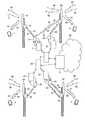
- FIG. 1is a schematic representation of a cellular telecommunications network
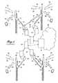
- FIG. 2is a representation of the conversion performed by a method according to the invention.
- FIG. 3is another representation of the conversion performed by a method according to the invention.
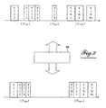
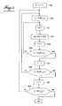
- FIGS. 4 to 7show steps of the method according to the invention.
- FIG. 8is a matrix for implementing the method according to the invention.
- FIG. 9is a diagram of a device according to the invention.
- FIG. 1shows a mobile telephone access network comprising several relay antennas 5 , 25 , 35 , 45 , and a mobile telephone core network 50 .
- Antenna 5picks up electromagnetic signals on uplinks 15 , 17 .
- uplink 15comes from a mobile terminal 1 .
- Antenna 5dually radiates electromagnetic signals on downlinks 16 , 18 .
- E.g., downlink 16is for mobile terminal 1 .
- antennas 25 , 35 , 45pick up electromagnetic signals on uplinks 20 , 21 , 30 , 31 , 54 , 40 , 41 .
- uplinks 21 , 31 , 41come from mobile terminals 2 , 3 , 4 .
- antennas 25 , 35 , 45radiate electromagnetic signals on downlinks 29 , 38 , 39 , 48 , 49 , 53 , 55 .
- E.g., downlinks 29 , 38 , 48are for mobile terminals 2 , 3 , 4 .
- radio transmission stations 7 , 27 , 37 , 47are linked to antennas 5 , 25 , 35 , 45 for transmitting and receiving the electromagnetic signals respectively radiated and picked up by the antennas.
- control stations 8 , 28for instance like a BSC (Base Station Controller) or RAN (Radio Access Network), each manage a group of transmission stations.
- switching centers 9for instance like an MSC (Mobile Switching Center), supervise groups of control stations.
- a so-called WRRH (Wireless Remote Radio Head) systemcomprises a unit 12 in close proximity to antenna 5 and a unit 13 in close proximity to radio transmission station 7 for setting up one or more wireless uplinks 6 from the antenna to the radio transmission station and one or more wireless downlinks 14 from the radio transmission station to the antenna, a unit 22 in close proximity to antenna 25 , and a unit 23 in close proximity to radio transmission station 27 for setting up one or more wireless uplinks 26 from the antenna to the radio transmission station and one or more wireless downlinks 24 from the radio transmission station to the antenna, a unit 32 in close proximity to the antenna 35 , and a unit 33 in close proximity to radio transmission station 37 for setting up one or more wireless uplinks 36 from the antenna to the radio transmission station and one or more wireless downlinks 34 from the radio transmission station to the antenna, a unit 42 in close proximity to the antenna 45 , and a unit 43 in close proximity to the radio transmission station 47 for setting up one or more wireless uplinks 46 from the antenna to the radio transmission station, and one or more wireless
- the method and device of the inventionare particularly advantageous for enabling the WRRH system to set up links between a base station (or part thereof) and the associated operator antennas, by means of wireless connections the operating frequency or frequencies of which are different from those commonly used by the operator.
- An independently managed sub-system of the WRRH systemcan be assigned to each radio transmission station 27 , 47 or a group of several radio transmission stations 7 , 37 , for instance in order to enable the radio transmission station to transmit electromagnetic signals to antenna 35 via a link 19 and receive electromagnetic signals from antenna 35 via a link 10 .
- the sub-system covering radio transmission stations 7 and 37can also cover all or part of radio transmission stations 27 , 47 , or even other radio transmission stations not represented, and even cover all of the radio transmission stations of the access network.
- the signals picked up by the antenna in the frequency band(s) of the operatorare filtered, frequency translated to other frequency bands and vice versa for signals radiated by the antenna.
- Such other frequency bandsare bands allowing for a link to be created between the base station and the associated antenna.
- each operatoris assigned the right to use several frequency bands, for instance among those of GSM, UMTS, or others mobile communication standards.
- This set of frequency bandsis designated as ⁇ F 1 ⁇ throughout the description.
- the set ⁇ F 1 ⁇comprises a number N of frequency bands assigned by way of example, but not to be restrictive, to an operator A.
- Each frequency bandis frequency sub-band shared, from which only some form a set ⁇ F 1,j,k ⁇ comprising a number Ns of frequency sub-bands F 1,j,k allocated to operator A.
- Each frequency sub-bandis called F 1,j,k , with the first index having the value 1 indicating that the sub-band belongs to a frequency band of the set of frequency bands ⁇ F 1 ⁇ , the second index j varying from 1 to N indicating the frequency band, i.e. the set ⁇ F 1,j,k ⁇ to which the frequency sub-band F 1,j,k , and index k varying from 1 to Ns, enumerating the frequency sub-bands of the frequency band having the index j.
- the space between sub-bandscan be occupied either by another operator B, C, . . . , or by applications not related to operator A.
- Fundamental frequency sub-bands allocated to or used by the operator A in the same frequency bandcan form a continuous spectrum collecting fundamental sub-bands in a single sub-band or a fragmented spectrum dispersing fundamental sub-bands into several separate sub-bands.
- the WRRH systemuses a frequency set designated by ⁇ F 2 ⁇ throughout the description, for carrying signals belonging to set ⁇ F 1 ⁇ between the radio transmission station (like a BTS, node B, or the like) and the antenna of the operator and vice versa.
- the frequency set ⁇ F 2 ⁇is limited in terms of bandwidth and can be shared with other applications not related to the applications of operator A.
- the method of the inventionapplies a conversion 59 to the signals at frequencies in the frequency bands of set ⁇ F 1 ⁇ in order to obtain signals at frequencies in frequency set ⁇ F 2 ⁇ so as to compress spectral occupation in the frequency set ⁇ F 2 ⁇ .
- Conversion 59is governed by rules for organizing, selecting, and optimizing the signals from band ⁇ F 1 ⁇ in order to efficiently fill the spectrum of frequency set ⁇ F 2 ⁇ .
- Frequenciesare translated by sub-band, directly from set ⁇ F 1 ⁇ to frequency set ⁇ F 2 ⁇ , without any demodulation of the signal, in other words without having to know whether the modulation of the signal is a frequency, amplitude, or phase modulation, and without having to know the coding of the signal on the carrier(s), for instance frequency hopping in CDMA (Code Division Multiple Access) or TD-CDMA (Time-Division-Code Division Multiple Access).
- Signalsare frequency translated without having to know the content thereof. In other words, frequency translation of each sub-band is independent from the signal as such. Frequency sub-bands of various operators can be translated independently from each other.
- sub-bands F 1,1,1 , F 1,1,2 , F 1,1,4are all extracted from set and are respectively translated to sub-bands F 2,1,1 , F 2,1,2 , F 2,1,4 , adjacent to each other in set ⁇ F 2,p,q ⁇ within frequency set ⁇ F 2 ).
- Sub-band F 1,j,k , (j ⁇ 1 ⁇ j ⁇ N)is entirely extracted from set ⁇ F 1,j,k ⁇ and is translated to sub-band F 2,j,k , adjacent to sub-band F 2,1,4 , in set ⁇ F 2,p,q ⁇ within frequency set (F 2 ).
- Sub-band F 1,N,1is only partially extracted from set ⁇ F 1,N,k ⁇ and extracted portion or segment is translated to sub-band F 2,N,1 , in set ⁇ F 2,m,n ⁇ within frequency set ⁇ F 2 ⁇ .
- Sub-band F 1,1,3is entirely extracted from set ⁇ F 1,1,k ⁇ and is translated to sub-band F 2,1,3 , related to sub-band F 2,N,1 in set within frequency set ⁇ F 2,m,n ⁇ within frequency set ⁇ F 2 ⁇ .
- Sub-bands F 1,N,k , F 1,N,Nsare all extracted from set ⁇ F 1,N,k ⁇ and are respectively translated to sub-bands F 2,N,k , F 2,N,Ns , related to each other in set ⁇ F 2,m,n ⁇ within frequency set ⁇ F 2 ⁇ .
- conversion 59performs defragmentation from set ⁇ F 1 ⁇ into set ⁇ F 2 ⁇ .
- the conversion 59is also applicable in reverse to signals at frequencies in the frequency bands of set ⁇ F 2 ⁇ in order to obtain signals at frequencies in frequency set ⁇ F 1 ⁇ so as to expand spectral occupation in frequency set (F 1 ). Conversion 59 will then alternately perform fragmentation from set ⁇ F 2 ⁇ into set ⁇ F 1 ⁇ .
- the signals of the operator picked up by antennas 5 , 25 , 35are organized, filtered, and spectrally optimized by a first conversion 59 a in order to be carried in links 6 , 10 , 36 of the wireless connection respectively in frequency sub-bands F 2,N,1 , F 2,1,3 , F 2,1,1 .
- a second conversion 59 bis then applied to the signals carried in links 6 , 10 , 36 of the wireless connection respectively in frequency sub-bands F 2,N,1 , F 2,1,3 , F 2,1,1 , in order to restore in radio transmission station 7 the signals in the frequency sub-bands F 3,N,1 , F 3,1,3 , and restore in the radio transmission station 37 the signals in the frequency sub-band F 3,1,1 into a frequency set ⁇ F 3 ⁇ .
- Frequency set ⁇ F 3 ⁇can also be the same set as the original one, thereby allowing one frequency set to be carried within another smaller one.
- the signals of the operator to be radiated by antennas 5 , 35are transmitted by radio transmission stations 7 , 37 for instance respectively in frequency sub-bands F 1,N,k , F 1,N,Ns , F 1,1,2 .
- the signals transmittedare organized, filtered, and spectrally optimized by the first conversion 59 a in order to be carried on links 14 , 19 , 34 of the wireless connection respectively in frequency sub-bands F 2,N,k , F 2,N,Ns , F 2,1,2 .
- the second conversion 59 bis then applied to the signals carried on links 14 , 19 , 34 of the wireless connection respectively in frequency sub-bands F 2,N,k , F 2,N,Ns , F 2,1,2 , so as to restore at antenna 5 , the signals in the frequency sub-bands F 3,N,k , and at antenna 35 , the signals in frequency sub-bands F 3,N,NS , F 3,1,2 , in frequency set ⁇ F 3 ⁇ .
- frequency set ⁇ F 3 ⁇can be the same set ⁇ F 1 ⁇ as the original one, thereby allowing one frequency set to be carried within another smaller one.
- FIG. 4shows method steps according to the invention.
- the frequency bands assigned to operator Aare taken into consideration by one execution of an initial step 100 pointing to a first frequency band having an index j set to 1 and by several preferably parallel executions of a step 103 each pointing to a value different from j comprised between 1 and N under the control of step 104 .
- the frequency sub-bands F 1,j,kallocated to and/or used by the operator are selected by the execution of the initial step 100 for the first frequency band and by several preferably parallel executions of a step 101 each pointing to a value different from k comprised between 1 and Ns, specific to each frequency band under the control of a step 102 adapting the value of the number Ns to the frequency band where the selection is performed.
- Frequencies fcomprised between a lower limit Inf(F 1,j,k ) observed in a step 106 and an upper limit Sup(F 1,j,k ) of each selected frequency sub-band F 1,j,k , observed in a step 109 , are passed by a step 108 so as to take a signal S(f) at the frequency f and translate it to a frequency f+ ⁇ f in a step 107 .
- the frequency translation value ⁇ fis determined in a step 110 for all of the frequencies of the selected frequency band.
- the frequency translation value ⁇ fis determined in a step 111 differently for different frequencies of the frequency set of the selected frequency band.
- the determination of the frequency translation ⁇ f in step 110is illustrated by steps 200 to 205 represented in FIG. 6 .
- One or several sets of incoming frequency sub-bands ⁇ F 2,p,q ⁇ , ⁇ F 2,m,n ⁇are previously defined for instance by the lower frequency limit Inf( ⁇ F 2,p,q ⁇ ), Inf( ⁇ F 2,m,n ⁇ ) thereof.
- the sets of frequency sub-bandsare initialized to empty sets by positioning upper limit values Sup( ⁇ F 2,p,q ⁇ ), Sup( ⁇ F 2,m,n ⁇ ) equal to the lower limit values Inf( ⁇ F 2,p,q ⁇ ), Inf( ⁇ F 2,m,n ⁇ ) of the sets.
- a step 205For each required frequency translation value ⁇ f from one frequency sub-band F 1,j,k in an execution of step 201 triggered by step 110 , a step 205 generates a frequency translation value ⁇ f. Between steps 201 and 205 , one or more steps each executes a rule relating the frequency translation value f to the frequency sub-band F 1,j,k to which it is applicable.
- a step 202executes an organizational rule which consists in assigning an incoming set ⁇ F 2,m,n ⁇ to the frequency sub-band F 1,j,k unique for the set of selected sub-bands, or different, for instance depending on logical criteria pre-established at the transmitters or receivers of the signals, on the granted data rates, communication protocols, semantics of content, or the like.
- a step 203executes an optimization rule which consists in translating the lower limit Inf(F 1,j,k ) of the frequency sub-band so as to map it to the upper limit Sup( ⁇ F 2,m,n ⁇ ), apart from a safety margin.
- a step 204 associated with step 203then updates the upper limit Sup( ⁇ F 2,m,n ⁇ ) so as to take into account the addition of sub-band F 1,j,k translated into set ⁇ F 2,m,n ⁇ .
- step 111The determination of the frequency translation ⁇ f in step 111 is illustrated by steps 210 to 215 represented in FIG. 7 .
- One or more sets of incoming frequency sub-bands ⁇ F 2,p,q ⁇ , ⁇ F 2,m,n ⁇are here previously defined for instance by the lower frequency limit Inf( ⁇ F 2,p,q ⁇ ), Inf( ⁇ F 2,m,n ⁇ ) thereof.
- the sets of frequency sub-bandsare initialized to empty sets by positioning upper limit values Sup( ⁇ F 2,p,q ⁇ ), Sup( ⁇ F 2,m,n ⁇ ) equal to the lower limit values Inf( ⁇ F 2,p,q ⁇ ), Inf( ⁇ F 2,m,n ⁇ ) of the sets.
- a step 215For each required frequency translation value ⁇ f from one frequency sub-band F 1,j,k in an execution of step 211 triggered by step 111 , a step 215 generates a frequency translation value ⁇ f. Between steps 211 and 215 , one or more steps each executes a rule relating the frequency translation value ⁇ f to a segment Seg(F 1,j,k ) of the frequency sub-band F 1,j,k to which it is applicable.
- a step 212executes an organizational rule which consists in assigning an incoming set ⁇ F 2,m,n ⁇ to segment Seg(F 1,j,k ), unique for all of the segments or even the selected sub-bands, or different, for instance depending on logical criteria pre-established at the transmitters or receivers of the signals, on granted data rates, communication protocols, semantics of content, or the like.
- a step 213executes an optimization rule which consists in translating the lower limit Inf(Seg(F 1,j,k )) of the frequency segment Seg(F 1,j,k ) so as to map it to the upper limit Sup( ⁇ F 2,m,n ⁇ ), apart from a safety margin.
- a step 214 associated with step 213then updates the upper limit Sup( ⁇ F 2,m,n ⁇ ) so as to take into account the addition of the segment Seg(F 1,j,k ) translated into set ⁇ F 2,m,n ⁇ .
- FIG. 8shows a matrix 60 useful for implementing the method of the invention.
- Each row of the matrix 60is dedicated to an input frequency sub-band F 1,j,k in set ⁇ F 1 ⁇ .
- Each column of matrix 60is dedicated to an output frequency sub-band F 2,m,n in set ⁇ F 2 ⁇ .
- the value 1means that a segment covering the entire width of the frequency sub-band is translated.
- a value comprised between 0 and 1means that only a segment covering part of the width of the frequency sub-band is translated.
- a value of 0.2means that only a segment covering 20% of the width of the frequency sub-bands is translated.
- the segment covering the entire width of frequency sub-band F 1,1,1is entirely carried on a segment of frequency sub-band F 2,1,1 .
- a frequency sub-bandIn a frequency sub-band, only part of the signals can possibly be used at a moment t. In order to optimize as finely as possible the frequency spectrum in the frequency set ⁇ F 2 ⁇ , only the segment(s) of the wanted sub-band will be treated. By introducing values smaller than 1 into the organizational, selection, and optimization matrix 60 , storage in the output spectrum of the signals actually used can then be optimized.
- a segment covering 20% of frequency sub-band F 1,N,1is carried on a segment of frequency sub-band F 2,N,1 .
- the frequency sub-band F 2,N,1can thus be divided into several segments to be carried on as many segments of frequency set ⁇ F 2 ⁇ .
- the method of the inventioncan be implemented by software by means of firmware which can be executed by digital signal processors (DSP) in the frequency bands compatible with the clock frequency of the processors.
- DSPdigital signal processors
- the method of the inventioncan also be implemented by means of hardware devices using analog components such as filters, switches, mixers, or the like, for instance for a simple frequency plane.
- digital architecturescan be built by combining various electronic components into chains comprising analog/digital converters (ADC) and digital/analog converters (DAC), followed by digital down converters (DDC), numerically controlled oscillators (NCO), then digital filters in turn followed by digital up converters (DUC) and again NCOs.
- ADCanalog/digital converters
- DACdigital/analog converters
- DDCdigital down converters
- NCOnumerically controlled oscillators
- DUCdigital up converters
- FPGAfield programmable gate arrays
- DSPsdigital signal processing circuits
- ASICapplication-specific integrated circuits
- FIG. 9shows a possible diagram of a device according to the invention.
- An interface module 70 , 80is tuned to each of the N frequency bands ⁇ F 1,j,k ⁇ from band ⁇ F 1,j,1 ⁇ to band ⁇ F 1,J,N ⁇ .
- the device for transmitting electromagnetic signals received on first frequency bands ⁇ F 1,j,1 ⁇ , ⁇ F 1,j,N ⁇comprises a bank of filters 64 , 66 downstream of the interface module 70 , each filter having a predetermined pass band or a pass band adjustable by a pass band adapter 74 , 76 so as to superimpose the pass band of the filter to a first frequency sub-band segment, and downstream of the interface module 80 a bank of filters 85 each having a predetermined pass band or a pass band adjustable by a pass band adapter 95 so as to superimpose the pass band of the filter to another first frequency sub-band segment.
- the variable filterscan be embodied by digital filters or analog filter bars with switches.
- the pass band adapters 74 , 76 , 95can be parameterized for instance starting with step 212 of the method executed for instance in a supervisory computer, not represented.
- a first frequency converter 61 , 63 , 82is sized to intersect a first sub-band F 1,j,k of the first frequency band with the pass band of the filter associated therewith.
- the frequency converteris embodied by an analog mixer or an NCO in order to perform a frequency change so that after conversion, the sub-band F 1,j,k is mapped to the pass band of the filter.
- frequency conversion or translationis predetermined or adjustable by an input setpoint generator 71 , 73 , 92 so as to intersect with the pass band of the filter associated therewith the first frequency sub-band in which signals considered wanted are received.
- the input setpoint generators 71 , 73 , 92can for instance be parameterized starting with steps 100 and 101 of the method, executed for instance in the supervisory computer.
- the first converterscontrolled or not by the first setpoint generators, combined with the filters controlled or not by the pass band adapters, are thus means for selecting frequency sub-bands.
- a second frequency converter 67 , 69 , 88is sized for bringing the pass band of the filter associated therewith to a second sub-band of a second frequency band ⁇ F 2,p,q ⁇ , ⁇ F 2,m,n ⁇ .
- the frequency converteris embodied by an analog mixer or an NCO for making a frequency change so that after conversion the sub-band F 1,j,k is mapped to a sub-band of the second frequency set at the filter output.
- frequency conversion or translationis predetermined or adjustable by an output setpoint generator 77 , 79 , 98 in order to release the second frequency sub-band obtained at the filter output, related to at least one other frequency sub-band of the second frequency set.
- the output setpoint generators 77 , 79 , 98can for instance be parameterized starting with steps 203 or 213 of the method, executed in the supervisory computer.
- the second converterscontrolled or not by the second setpoint generators, combined with the filters controlled or not by the pass band adapters, are thus means for associating second frequency sub-bands with the first frequency sub-bands and frequency translating in view of transposing the signals received.
- a summing and routing module 90then directs the signals at the output of second converters to interface modules 56 , 57 , e.g., each dedicated to a frequency band of the second set ⁇ F 2 ⁇ , or even to the medium intended for transmitting the signals.
- interface module 56is dedicated to the wireless link 52 or 51
- interface module 57is dedicated to the wireless link 46 or 44 .
- interface module 56is dedicated to the wireless link 14 or 10
- interface module 57is dedicated to the wireless link 19 or 36 .
- the summing and routing module 90 of each device installed in units 12 , 13 , 32 , 33is preferably managed by the supervisory computer.
- the reverse summing and routing module 90the signals received from the interface modules 56 , 57 for instance each dedicated to a frequency band of the second set ⁇ F 2 ⁇ , intended for interface modules 70 , 80 dedicated to the pass band of the first set ⁇ F 1 ⁇ , wherein the signals received are to be retransmitted.
- interface module 56is dedicated to the wireless link 51 or 52 , e.g., for GSM, and interface module 57 is dedicated to the wireless link 44 or 46 , e.g. for UMTS.
- the signals received on link 51 by interface module 56 in frequency band ⁇ F 2,p,q ⁇are directed toward interface module 70 tuned to a radiofrequency band of GSM.
- the signals received on link 44 by interface module 57 in frequency band ⁇ F 2,m,n ⁇are directed toward the interface module 80 tuned to a UMTS radiofrequency band.
- interface module 56is dedicated to the wireless communication link 19 with unit 13
- interface module 57is dedicated to the wireless communication link 34 with unit 33 .
- Signals from the signals received on link 19 by interface module 56 in frequency bands ⁇ F 2,p,q ⁇are for instance for the mobile terminal 1 in the handover phase from antenna 5 to antenna 35 , they are then directed toward interface module 70 tuned to a radiofrequency band comprising a sub-band F 1,1,k which can be assigned to mobile terminal 1 .
- Signals from the signals received on link 34 by interface module 57 in frequency band ⁇ F 2,m,n ⁇for instance involve the mobile terminal 3 covered by antenna 35 ; they are directed toward interface module 80 tuned to a communication radiofrequency band with mobile terminal 3 .
- the device for transmitting electromagnetic signals received on frequency bands ⁇ F 2,p,q ⁇ , ⁇ F 2,m,n ⁇comprises downstream of summing and routing module 90 a filter bank 65 , 84 , 86 each having a predetermined pass band or a pass band adjustable by a pass band adapter 75 , 94 , 96 so as to superimpose the pass band of the filter to an input frequency sub-band segment.
- the variable filterscan be embodied by digital filters or analog filter bars with switches.
- the pass band adapters 75 , 94 , 96can for instance be parameterized starting with step 212 of the method executed for instance in the supervisory computer, not represented.
- a first frequency converter 68 , 87 , 89is sized for intersecting a first sub-band F 2,m,n of the first frequency band with the pass band of the filter associated therewith.
- the frequency converteris embodied by an analog mixer or an NCO for making a frequency change so that after conversion the sub-band F 2,m,n is mapped to the pass band of the filter.
- frequency conversion or translationis predetermined or adjustable by an input setpoint generator 78 , 97 , 99 so as to intersect the pass band of the filter associated therewith the first frequency sub-band in which signals considered wanted are received.
- the input setpoint generators 78 , 97 , 99can for instance be parameterized starting with steps 100 and 101 of the method executed in the supervisory computer.
- the first converterscontrolled or not by the first setpoint generators, combined with the filters controlled or not by the pass band adapters, are thus means for selecting frequency sub-bands.
- a second frequency converter 62 , 81 , 83is sized for bringing the pass band of the filter associated therewith to a second sub-band of a second frequency band ⁇ F 1,1,k ⁇ , ⁇ F 1,N,k ⁇ .
- the frequency converteris embodied by an analog mixer or an NCO for making a frequency change so that after conversion, sub-band F 2,m,n is mapped to a sub-band of the second frequency set at the filter output.
- frequency conversion or translationis predetermined or adjustable by an output setpoint generator 72 , 91 , 93 so as to release the second frequency sub-band obtained at the output of the filter, related to at least one other frequency sub-band of the second frequency set.
- the output setpoint generators 72 , 91 , 93can for instance be parameterized starting with steps 203 or 213 of the method executed in the supervisory computer.
- the second converterscontrolled or not by the second setpoint generators, combined with the filters controlled or not by the pass band adapters, are thus means for associating second frequency sub-bands with the first frequency sub-bands and frequency translating in view of transposing the signals received.
- the dotted lines between frequency converters 62 and 63 , 68 and 69 , or 81 and 82 , 87 and 88indicate that several uplinks or downlinks are possible.
- the diagram of FIG. 2is simply one of several examples. The device represented may also comprise only down-arrows.
- Spectral configurationcan be static, reconfigurable, or dynamic. Dynamic response may depend on different parameters, for instance quality of service (QoS), spectrum usage, interferences, spectrum usage rules, network developments, spectrum modifications, or the like.
- QoSquality of service
- the systemmay also incorporate self-detecting methods, for instance of collisions or saturation, allowing for automatic self-reconfiguration.
- selecting receiving frequency sub-bandscan be done for instance for a first operator A, then for a second operator B, then for a third operator C, and so on for several operators.
Landscapes
- Engineering & Computer Science (AREA)
- Signal Processing (AREA)
- Computer Networks & Wireless Communication (AREA)
- Mobile Radio Communication Systems (AREA)
- Circuits Of Receivers In General (AREA)
- Radio Transmission System (AREA)
Abstract
Description
- selecting first frequency sub-bands forming a first set of frequency sub-bands of said first frequency band(s);
- in accordance with organizational rules, associating with each first frequency sub-band forming said first set one or more second sets of frequency sub-bands forming one or more second frequency bands; and
- in accordance with optimization rules, determining frequency translations for transposing signals received in the first frequency sub-bands to signals transmitted in the second frequency band(s).
- a bank of filters each having a pass band;
- at the input of each filter, a first frequency converter intersecting a first sub-band of a first frequency band with the pass band of the filter associated therewith; and
- at the output of each filter, a second frequency converter bringing the pass band of the filter associated therewith to a second sub-band of a second frequency band.
- selecting first frequency sub-bands forming a first set {F1,1,k} of frequency sub-bands of said first frequency band(s);
- in accordance with organizational rules, associating with each first frequency sub-band F1,1,k, F1,1,2, F1,1,3, F1,1,4forming said first set one or more second sets {F2,p,q}, {F2,m,n} of frequency sub-bands F2,1,k, F2,1,2, F2,1,3, F2,1,4forming one or more second frequency bands; and
- in accordance with optimization rules, determining frequency translations so as to transpose signals received in the first frequency sub-bands to signals transmitted in the second frequency band(s).
Claims (14)
Applications Claiming Priority (3)
| Application Number | Priority Date | Filing Date | Title |
|---|---|---|---|
| FR1051418 | 2010-02-26 | ||
| FR1051418AFR2956934B1 (en) | 2010-02-26 | 2010-02-26 | METHOD AND DEVICE FOR TRANSMITTING / RECEIVING ELECTROMAGNETIC SIGNALS RECEIVED / EMITTED ON ONE OR MORE FIRST FREQUENCY BANDS. |
| PCT/FR2011/050380WO2011104481A1 (en) | 2010-02-26 | 2011-02-24 | Method and device for sending/receiving electromagnetic signals received/sent on one or more first frequency bands |
Related Parent Applications (1)
| Application Number | Title | Priority Date | Filing Date |
|---|---|---|---|
| PCT/FR2011/050380A-371-Of-InternationalWO2011104481A1 (en) | 2010-02-26 | 2011-02-24 | Method and device for sending/receiving electromagnetic signals received/sent on one or more first frequency bands |
Related Child Applications (1)
| Application Number | Title | Priority Date | Filing Date |
|---|---|---|---|
| US14/705,964ContinuationUS9320040B2 (en) | 2010-02-26 | 2015-05-06 | Method and device for sending/receiving electromagnetic signals received/sent on one or more first frequency bands |
Publications (2)
| Publication Number | Publication Date |
|---|---|
| US20130101299A1 US20130101299A1 (en) | 2013-04-25 |
| US9083440B2true US9083440B2 (en) | 2015-07-14 |
Family
ID=42990121
Family Applications (2)
| Application Number | Title | Priority Date | Filing Date |
|---|---|---|---|
| US13/580,687Expired - Fee RelatedUS9083440B2 (en) | 2010-02-26 | 2011-02-24 | Method and device for sending/receiving electromagnetic signals received/sent on one or more first frequency bands |
| US14/705,964Expired - Fee RelatedUS9320040B2 (en) | 2010-02-26 | 2015-05-06 | Method and device for sending/receiving electromagnetic signals received/sent on one or more first frequency bands |
Family Applications After (1)
| Application Number | Title | Priority Date | Filing Date |
|---|---|---|---|
| US14/705,964Expired - Fee RelatedUS9320040B2 (en) | 2010-02-26 | 2015-05-06 | Method and device for sending/receiving electromagnetic signals received/sent on one or more first frequency bands |
Country Status (10)
| Country | Link |
|---|---|
| US (2) | US9083440B2 (en) |
| EP (1) | EP2540136B1 (en) |
| JP (1) | JP5911811B2 (en) |
| KR (1) | KR20130049175A (en) |
| CN (1) | CN102918923B (en) |
| BR (1) | BR112012021318A2 (en) |
| CA (1) | CA2790815A1 (en) |
| EA (1) | EA201201190A1 (en) |
| FR (1) | FR2956934B1 (en) |
| WO (1) | WO2011104481A1 (en) |
Cited By (3)
| Publication number | Priority date | Publication date | Assignee | Title |
|---|---|---|---|---|
| US20120264380A1 (en)* | 2011-03-14 | 2012-10-18 | Nujira Limited | Polar Amplification Transmitter Distortion Reduction |
| US9320040B2 (en) | 2010-02-26 | 2016-04-19 | E-Blink | Method and device for sending/receiving electromagnetic signals received/sent on one or more first frequency bands |
| US10009790B2 (en) | 2012-05-04 | 2018-06-26 | EBlink NV | Wide area transport networks for mobile radio access networks and methods of use |
Families Citing this family (3)
| Publication number | Priority date | Publication date | Assignee | Title |
|---|---|---|---|---|
| JP5708081B2 (en)* | 2011-03-16 | 2015-04-30 | 富士通株式会社 | Optical network system |
| US20170250927A1 (en)* | 2013-12-23 | 2017-08-31 | Dali Systems Co. Ltd. | Virtual radio access network using software-defined network of remotes and digital multiplexing switches |
| US10383024B2 (en) | 2015-03-10 | 2019-08-13 | Analog Devices, Inc. | System and method for efficient fronthaul communication for wireless communication |
Citations (73)
| Publication number | Priority date | Publication date | Assignee | Title |
|---|---|---|---|---|
| DE3108901A1 (en) | 1981-03-09 | 1982-09-30 | Wilhelm Sihn jr. KG, 7532 Niefern-Öschelbronn | Method for detecting and processing a pilot signal |
| JPS59154827A (en) | 1983-02-24 | 1984-09-03 | Matsushita Electric Ind Co Ltd | Radio relaying method |
| US4806878A (en) | 1985-09-18 | 1989-02-21 | Plessey Overseas Limited | Phase comparator lock detect circuit and a synthesizer using same |
| US4827395A (en) | 1983-04-21 | 1989-05-02 | Intelli-Tech Corporation | Manufacturing monitoring and control systems |
| US5513176A (en) | 1990-12-07 | 1996-04-30 | Qualcomm Incorporated | Dual distributed antenna system |
| US5602834A (en) | 1990-12-07 | 1997-02-11 | Qualcomm Incorporated | Linear coverage area antenna system for a CDMA communication system |
| US5652765A (en) | 1993-08-06 | 1997-07-29 | Ntt Mobile Communications Network Inc. | Receiver and repeater for spread spectrum communications |
| US5768268A (en) | 1995-07-19 | 1998-06-16 | Watkins Johnson Company | Wideband base station architecture for digital cellular communications system |
| US5842002A (en) | 1994-06-01 | 1998-11-24 | Quantum Leap Innovations, Inc. | Computer virus trap |
| US5867763A (en) | 1996-02-08 | 1999-02-02 | Qualcomm Incorporated | Method and apparatus for integration of a wireless communication system with a cable T.V. system |
| US5940598A (en) | 1997-01-28 | 1999-08-17 | Bell Atlantic Network Services, Inc. | Telecommunications network to internetwork universal server |
| US5969678A (en) | 1995-06-06 | 1999-10-19 | Wayport, Inc. | System for hybrid wired and wireless geographic-based communications service |
| US6049315A (en) | 1997-07-01 | 2000-04-11 | Lucent Technologies, Inc. | Repeater isolation through antenna polarization diversity |
| US6072994A (en) | 1995-08-31 | 2000-06-06 | Northrop Grumman Corporation | Digitally programmable multifunction radio system architecture |
| US6094677A (en) | 1997-05-30 | 2000-07-25 | International Business Machines Corporation | Methods, systems and computer program products for providing insertions during delays in interactive systems |
| US6122529A (en) | 1998-03-17 | 2000-09-19 | Transcept, Inc. | Simulcast with hierarchical cell structure overlay |
| US6223021B1 (en)* | 1997-12-24 | 2001-04-24 | Transcept, Inc. | Signal filtering in a transceiver for a wireless telephone system |
| US20010011009A1 (en) | 1996-04-22 | 2001-08-02 | Toshio Harada | Underground information communication system and related manhole cover |
| US20010031624A1 (en) | 1999-12-29 | 2001-10-18 | Schmutz Thomas R. | Discrete power level coding for indicating uplink mobile receive level in a wireless repeater system |
| US6339611B1 (en) | 1998-11-09 | 2002-01-15 | Qualcomm Inc. | Method and apparatus for cross polarized isolation in a communication system |
| US6349214B1 (en) | 1999-05-21 | 2002-02-19 | Warren L. Braun | Synchronization of broadcast facilities via satellite |
| US20020028655A1 (en) | 2000-07-14 | 2002-03-07 | Rosener Douglas K. | Repeater system |
| US6385435B1 (en) | 2000-04-20 | 2002-05-07 | Jhong Sam Lee | Coupled interference concellation system for wideband repeaters in a cellular system |
| US6389059B1 (en) | 1991-05-13 | 2002-05-14 | Xircom Wireless, Inc. | Multi-band, multi-mode spread-spectrum communication system |
| US20020072375A1 (en) | 2000-11-13 | 2002-06-13 | Huslig Daniel J. | Apparatus, system and method for allocating upstream and downstream channels in a cellular communication system having a wireless backhaul |
| US20020147978A1 (en) | 2001-04-04 | 2002-10-10 | Alex Dolgonos | Hybrid cable/wireless communications system |
| US20030016701A1 (en) | 2001-07-23 | 2003-01-23 | Hinson Scott R. | Distributed block frequency converter |
| US20030027597A1 (en) | 2001-07-31 | 2003-02-06 | Lagrotta James T. | Use of over-the-air optical link within a geographically distributed base station |
| US20030140256A1 (en) | 2002-01-24 | 2003-07-24 | Swisscom Mobile Ag | Wireless local communication network, access control method for a wireless local communication network and devices suitable therefor |
| US6603956B1 (en) | 1999-08-20 | 2003-08-05 | Sensing Tech Corp | Radio repeater using the non-radiative dielectric waveguide |
| US6640110B1 (en) | 1997-03-03 | 2003-10-28 | Celletra Ltd. | Scalable cellular communications system |
| US20030232595A1 (en) | 2002-04-17 | 2003-12-18 | Baker Michael R. | Wireless repeater apparatus, system, and method |
| US20040015712A1 (en) | 2002-07-19 | 2004-01-22 | Peter Szor | Heuristic detection of malicious computer code by page tracking |
| US20040048596A1 (en) | 2002-09-10 | 2004-03-11 | Nortel Networks Limited | Method and apparatus for extending high bandwidth communication services to the edge of the network |
| US20040052226A1 (en) | 2002-09-17 | 2004-03-18 | Frank Ed H. | Method and system for providing an intelligent switch in a hybrid wired/wireless local area network |
| WO2004027635A1 (en) | 2002-09-17 | 2004-04-01 | Broadcom Corporation | A wireless access point in a hybrid wire/wireless network |
| US20040077345A1 (en) | 2002-08-02 | 2004-04-22 | Turner R. Brough | Methods and apparatus for network signal aggregation and bandwidth reduction |
| WO2004045125A2 (en) | 2002-11-07 | 2004-05-27 | Magis Networks, Inc. | Hybrid wired/wireless local area networking |
| US20040145849A1 (en) | 2002-11-15 | 2004-07-29 | Chang Byung-Ho | Surge protection device and method |
| US20040166802A1 (en) | 2003-02-26 | 2004-08-26 | Ems Technologies, Inc. | Cellular signal enhancer |
| EP1501215A1 (en) | 2002-04-12 | 2005-01-26 | Telefonica, S.A. | Access method and gsm repeater system with spectral exchange between the 900 and 1800 mhz gsm wave frequencies |
| US20050085267A1 (en) | 2001-12-26 | 2005-04-21 | Paul Lemson | Modular base station antenna control system |
| US20050101349A1 (en) | 2003-11-10 | 2005-05-12 | Nokia Corporation | Open modem - RFU interface |
| EP1534027A2 (en) | 2003-11-24 | 2005-05-25 | Lucent Technologies Inc. | Wireless distributed base station |
| US6904266B1 (en) | 2002-02-19 | 2005-06-07 | Navini Networks, Inc. | Wireless enhancer using a switch matrix |
| US20050130587A1 (en) | 2003-12-05 | 2005-06-16 | Ntt Docomo, Inc | Radio repeater and radio relay transmission method |
| US20050176368A1 (en) | 2003-03-07 | 2005-08-11 | Spotwave Wireless Inc. | Distributed adaptive repeater system |
| US20050256963A1 (en) | 2002-10-01 | 2005-11-17 | Robert Bosch Gmbh | Wireless local area network with repeater for enhancing network coverage |
| US7010325B1 (en) | 2002-06-11 | 2006-03-07 | Sprint Spectrum L.P. | Wireless repeater with wireless telephone adapter |
| US20060068848A1 (en) | 2003-01-28 | 2006-03-30 | Celletra Ltd. | System and method for load distribution between base station sectors |
| EP1648099A1 (en) | 2003-07-18 | 2006-04-19 | Da Tang Mobile Communications Equipment Co., Ltd. | Bi-directional synchronization forwarding method and device for wireless signals |
| US20060140161A1 (en) | 2002-09-13 | 2006-06-29 | Spencer Stephens | Network access points using multiple devices |
| US20060205343A1 (en) | 2005-03-11 | 2006-09-14 | Runyon Donald L | Wireless repeater with feedback suppression features |
| US7123911B1 (en) | 2002-08-08 | 2006-10-17 | Sprint Spectrum L.P. | Method and system of wireless signal repeating |
| US20070053409A1 (en)* | 2003-11-17 | 2007-03-08 | Jukka Reunamaki | Wideband communication method |
| US20070091896A1 (en) | 2005-10-26 | 2007-04-26 | Utstarcom Telecom Co., Ltd | CPRI-based multiprotocol signal transmission method and apparatus in distributed base station system |
| US20070147278A1 (en) | 2002-05-31 | 2007-06-28 | Adc Wireless Solutions Llc | System and method for retransmission of data |
| US20070243824A1 (en) | 2003-11-17 | 2007-10-18 | Alain Roland | Mobile Telephone Network for Communication Between Two Communication Sets |
| US20080181171A1 (en) | 2007-01-25 | 2008-07-31 | Adc Telecommunications, Inc. | Distributed remote base station system |
| US7463673B2 (en) | 2004-02-16 | 2008-12-09 | Ntt Docomo, Inc. | Radio relay system, radio relay apparatus, and radio relay method |
| US20090003831A1 (en) | 2005-12-31 | 2009-01-01 | Huawei Technologies Co., Ltd. | Network Interconnection System And Method With Separated Controlling And Bearing |
| US7535972B2 (en) | 2005-06-24 | 2009-05-19 | Broadcom Corporation | Programmable transmitter |
| EP2099183A1 (en) | 2006-12-04 | 2009-09-09 | ZTE Corporation | A wireless communication apparatus and the configuration method thereof |
| US20090252267A1 (en) | 2006-07-07 | 2009-10-08 | E-Blink | Method of synchronizing two electronic devices of a wireless link, in particular of a mobile telephone network and system for implementing this method |
| US20090325479A1 (en) | 2008-06-25 | 2009-12-31 | Qualcomm Incorporated | Relay antenna indexing for shared antenna communication |
| US7680203B2 (en) | 2005-03-29 | 2010-03-16 | Sony Corporation | Wireless communication apparatus and wireless communication method |
| US20100142598A1 (en) | 2006-12-05 | 2010-06-10 | Commonwealth Scientific And Industrial Research Organisation | Wireless Frequency-Domain Multi-Channel Communications |
| US7738579B2 (en) | 2003-08-08 | 2010-06-15 | Intel Corporation | Systems and methods for adaptive bit loading in a multiple antenna orthogonal frequency division multiplexed communication system |
| US7801230B2 (en) | 2006-09-29 | 2010-09-21 | Samsung Electronics Co., Ltd. | Channel estimation method and apparatus in an orthogonal frequency division multiplexing (OFDM) wireless communication system |
| US20120100847A1 (en) | 2010-10-26 | 2012-04-26 | At&T Intellectual Property I, L.P. | Performance diagnosis of wireless equipment and a wireless network over out-of-band communication |
| US20120140654A1 (en) | 2010-12-01 | 2012-06-07 | Electronics And Telecommunications Research Institute | Method and apparatus for managing backup channel in multi-channel environment |
| US8275310B2 (en) | 2006-09-04 | 2012-09-25 | E-Blink | Wireless system for transmitting data between a base station and a relay antenna of a mobile telephony network |
| US20130294541A1 (en) | 2012-05-04 | 2013-11-07 | E-Blink | High Capacity Wireless Communications Systems and Methods |
Family Cites Families (31)
| Publication number | Priority date | Publication date | Assignee | Title |
|---|---|---|---|---|
| US4487925A (en) | 1983-01-28 | 1984-12-11 | Bristol-Myers Company | Rebeccamycin and process for its preparation |
| JPS59154827U (en) | 1983-03-31 | 1984-10-17 | 日産自動車株式会社 | Internal combustion engine supercharging device |
| EP0160429A3 (en) | 1984-04-30 | 1986-12-17 | General Motors Corporation | Self pressurized shock-dampening device |
| JPH0635520Y2 (en) | 1990-09-14 | 1994-09-14 | 株式会社アサヒ電機製作所 | Removal Tool for Cylindrical Fuses |
| IL100213A (en) | 1990-12-07 | 1995-03-30 | Qualcomm Inc | CDMA microcellular telephone system and distributed antenna system therefor |
| JP2858514B2 (en) | 1992-11-16 | 1999-02-17 | 日本電信電話株式会社 | Wireless communication system |
| JP2833580B2 (en) | 1996-04-19 | 1998-12-09 | 日本電気株式会社 | Full-text index creation device and full-text database search device |
| US6212397B1 (en) | 1996-12-23 | 2001-04-03 | Texas Instruments Incorporated | Method and system for controlling remote multipoint stations |
| SE509433C2 (en) | 1997-05-16 | 1999-01-25 | Ericsson Telefon Ab L M | Antenna system for a mobile communication station in a mobile telecommunications network and method for radio communication |
| JPH1141158A (en) | 1997-07-16 | 1999-02-12 | Kokusai Electric Co Ltd | Booster device |
| US7339568B2 (en) | 1999-04-16 | 2008-03-04 | Samsung Electronics Co., Ltd. | Signal transmission film and a liquid crystal display panel having the same |
| US6349215B1 (en) | 1999-05-21 | 2002-02-19 | Warren L. Braun | Synchronization of broadcast facilities via microwave tone |
| JP2001016153A (en) | 1999-06-30 | 2001-01-19 | Hitachi Kokusai Electric Inc | Playback repeater |
| US7068973B1 (en) | 2000-02-25 | 2006-06-27 | Andrew Corporation | Method and apparatus for retransmitting received satellite signals inside a structure |
| US6760366B1 (en) | 1999-11-29 | 2004-07-06 | Qualcomm Incorporated | Method and apparatus for pilot search using a matched filter |
| KR100334558B1 (en) | 2000-05-24 | 2002-05-03 | 윤종용 | Wire·wireless unified in-building communication method and system |
| JP4151243B2 (en) | 2001-07-26 | 2008-09-17 | 三菱電機株式会社 | Multipath noise removal method and removal apparatus, FM receiver |
| EP1457069A1 (en) | 2001-12-21 | 2004-09-15 | Hitachi, Ltd. | Mobile communications network using mobile station with relay-function and method for rewarding relay activities of mobile station |
| CN1653784A (en) | 2002-03-08 | 2005-08-10 | Ipr特许公司 | Adaptive receive and omnidirectional transmit antenna array |
| US20040157551A1 (en) | 2002-06-21 | 2004-08-12 | Tantivy Communications, Inc | Repeater for extending range of time division duplex communication system |
| EP1597839B1 (en) | 2003-02-26 | 2007-08-15 | Andrew Corporation | Cellular signal enhancer |
| JP4529375B2 (en) | 2003-04-28 | 2010-08-25 | パナソニック電工株式会社 | Wireless relay device |
| JP4291093B2 (en) | 2003-09-11 | 2009-07-08 | 本田技研工業株式会社 | Method for estimating joint moments of biped walking objects |
| JP2006067338A (en)* | 2004-08-27 | 2006-03-09 | Matsushita Electric Ind Co Ltd | Diversity relay device |
| US20060105705A1 (en) | 2004-11-16 | 2006-05-18 | Andrew Corporation | Consumer installer repeater for wireless communication |
| DE602006010813D1 (en)* | 2006-04-24 | 2010-01-14 | Ntt Docomo Inc | Method and system for radio channel estimation in a wireless communication system, relay station and receiver |
| CN101512943B (en)* | 2006-07-10 | 2015-09-02 | 国立大学法人大阪大学 | Transfer approach, transfer system, dispensing device and receiving system |
| JP2008072218A (en)* | 2006-09-12 | 2008-03-27 | Toshiba Corp | Digital broadcast wave relay device |
| JP5042144B2 (en)* | 2008-06-27 | 2012-10-03 | 日本電信電話株式会社 | Wireless relay transmission system, relay station apparatus, and wireless relay transmission method |
| JP2010200241A (en)* | 2009-02-27 | 2010-09-09 | Samsung Yokohama Research Institute Co Ltd | Wireless relay station, wireless communication system, and wireless communication method |
| FR2956934B1 (en) | 2010-02-26 | 2012-09-28 | Blink E | METHOD AND DEVICE FOR TRANSMITTING / RECEIVING ELECTROMAGNETIC SIGNALS RECEIVED / EMITTED ON ONE OR MORE FIRST FREQUENCY BANDS. |
- 2010
- 2010-02-26FRFR1051418Apatent/FR2956934B1/ennot_activeExpired - Fee Related
- 2011
- 2011-02-24USUS13/580,687patent/US9083440B2/ennot_activeExpired - Fee Related
- 2011-02-24EAEA201201190Apatent/EA201201190A1/enunknown
- 2011-02-24EPEP11712630.0Apatent/EP2540136B1/enactiveActive
- 2011-02-24WOPCT/FR2011/050380patent/WO2011104481A1/enactiveApplication Filing
- 2011-02-24CNCN201180020376.3Apatent/CN102918923B/ennot_activeExpired - Fee Related
- 2011-02-24BRBR112012021318Apatent/BR112012021318A2/ennot_activeIP Right Cessation
- 2011-02-24KRKR1020127024914Apatent/KR20130049175A/ennot_activeCeased
- 2011-02-24CACA2790815Apatent/CA2790815A1/ennot_activeAbandoned
- 2011-02-24JPJP2012554399Apatent/JP5911811B2/ennot_activeExpired - Fee Related
- 2015
- 2015-05-06USUS14/705,964patent/US9320040B2/ennot_activeExpired - Fee Related
Patent Citations (87)
| Publication number | Priority date | Publication date | Assignee | Title |
|---|---|---|---|---|
| DE3108901A1 (en) | 1981-03-09 | 1982-09-30 | Wilhelm Sihn jr. KG, 7532 Niefern-Öschelbronn | Method for detecting and processing a pilot signal |
| JPS59154827A (en) | 1983-02-24 | 1984-09-03 | Matsushita Electric Ind Co Ltd | Radio relaying method |
| US4827395A (en) | 1983-04-21 | 1989-05-02 | Intelli-Tech Corporation | Manufacturing monitoring and control systems |
| US4806878A (en) | 1985-09-18 | 1989-02-21 | Plessey Overseas Limited | Phase comparator lock detect circuit and a synthesizer using same |
| US5513176A (en) | 1990-12-07 | 1996-04-30 | Qualcomm Incorporated | Dual distributed antenna system |
| US5533011A (en) | 1990-12-07 | 1996-07-02 | Qualcomm Incorporated | Dual distributed antenna system |
| US5602834A (en) | 1990-12-07 | 1997-02-11 | Qualcomm Incorporated | Linear coverage area antenna system for a CDMA communication system |
| US6389059B1 (en) | 1991-05-13 | 2002-05-14 | Xircom Wireless, Inc. | Multi-band, multi-mode spread-spectrum communication system |
| US5652765A (en) | 1993-08-06 | 1997-07-29 | Ntt Mobile Communications Network Inc. | Receiver and repeater for spread spectrum communications |
| US5842002A (en) | 1994-06-01 | 1998-11-24 | Quantum Leap Innovations, Inc. | Computer virus trap |
| US5969678A (en) | 1995-06-06 | 1999-10-19 | Wayport, Inc. | System for hybrid wired and wireless geographic-based communications service |
| US5768268A (en) | 1995-07-19 | 1998-06-16 | Watkins Johnson Company | Wideband base station architecture for digital cellular communications system |
| US6072994A (en) | 1995-08-31 | 2000-06-06 | Northrop Grumman Corporation | Digitally programmable multifunction radio system architecture |
| JP2000504898A (en) | 1996-02-08 | 2000-04-18 | カルコム・インコーポレーテッド | Method and apparatus for integration of a wireless communication system and a cable television system |
| US5867763A (en) | 1996-02-08 | 1999-02-02 | Qualcomm Incorporated | Method and apparatus for integration of a wireless communication system with a cable T.V. system |
| US20010011009A1 (en) | 1996-04-22 | 2001-08-02 | Toshio Harada | Underground information communication system and related manhole cover |
| US5940598A (en) | 1997-01-28 | 1999-08-17 | Bell Atlantic Network Services, Inc. | Telecommunications network to internetwork universal server |
| US6640110B1 (en) | 1997-03-03 | 2003-10-28 | Celletra Ltd. | Scalable cellular communications system |
| US6094677A (en) | 1997-05-30 | 2000-07-25 | International Business Machines Corporation | Methods, systems and computer program products for providing insertions during delays in interactive systems |
| US6049315A (en) | 1997-07-01 | 2000-04-11 | Lucent Technologies, Inc. | Repeater isolation through antenna polarization diversity |
| US6223021B1 (en)* | 1997-12-24 | 2001-04-24 | Transcept, Inc. | Signal filtering in a transceiver for a wireless telephone system |
| US6122529A (en) | 1998-03-17 | 2000-09-19 | Transcept, Inc. | Simulcast with hierarchical cell structure overlay |
| US6339611B1 (en) | 1998-11-09 | 2002-01-15 | Qualcomm Inc. | Method and apparatus for cross polarized isolation in a communication system |
| US6349214B1 (en) | 1999-05-21 | 2002-02-19 | Warren L. Braun | Synchronization of broadcast facilities via satellite |
| US6603956B1 (en) | 1999-08-20 | 2003-08-05 | Sensing Tech Corp | Radio repeater using the non-radiative dielectric waveguide |
| US20010031624A1 (en) | 1999-12-29 | 2001-10-18 | Schmutz Thomas R. | Discrete power level coding for indicating uplink mobile receive level in a wireless repeater system |
| US6385435B1 (en) | 2000-04-20 | 2002-05-07 | Jhong Sam Lee | Coupled interference concellation system for wideband repeaters in a cellular system |
| US20020028655A1 (en) | 2000-07-14 | 2002-03-07 | Rosener Douglas K. | Repeater system |
| US20020072375A1 (en) | 2000-11-13 | 2002-06-13 | Huslig Daniel J. | Apparatus, system and method for allocating upstream and downstream channels in a cellular communication system having a wireless backhaul |
| US20020147978A1 (en) | 2001-04-04 | 2002-10-10 | Alex Dolgonos | Hybrid cable/wireless communications system |
| US20030016701A1 (en) | 2001-07-23 | 2003-01-23 | Hinson Scott R. | Distributed block frequency converter |
| US20030027597A1 (en) | 2001-07-31 | 2003-02-06 | Lagrotta James T. | Use of over-the-air optical link within a geographically distributed base station |
| US20050085267A1 (en) | 2001-12-26 | 2005-04-21 | Paul Lemson | Modular base station antenna control system |
| US20030140256A1 (en) | 2002-01-24 | 2003-07-24 | Swisscom Mobile Ag | Wireless local communication network, access control method for a wireless local communication network and devices suitable therefor |
| US6904266B1 (en) | 2002-02-19 | 2005-06-07 | Navini Networks, Inc. | Wireless enhancer using a switch matrix |
| EP1501215A1 (en) | 2002-04-12 | 2005-01-26 | Telefonica, S.A. | Access method and gsm repeater system with spectral exchange between the 900 and 1800 mhz gsm wave frequencies |
| US20030232595A1 (en) | 2002-04-17 | 2003-12-18 | Baker Michael R. | Wireless repeater apparatus, system, and method |
| US20070147278A1 (en) | 2002-05-31 | 2007-06-28 | Adc Wireless Solutions Llc | System and method for retransmission of data |
| US7010325B1 (en) | 2002-06-11 | 2006-03-07 | Sprint Spectrum L.P. | Wireless repeater with wireless telephone adapter |
| US20040015712A1 (en) | 2002-07-19 | 2004-01-22 | Peter Szor | Heuristic detection of malicious computer code by page tracking |
| US20040077345A1 (en) | 2002-08-02 | 2004-04-22 | Turner R. Brough | Methods and apparatus for network signal aggregation and bandwidth reduction |
| US7123911B1 (en) | 2002-08-08 | 2006-10-17 | Sprint Spectrum L.P. | Method and system of wireless signal repeating |
| US20040048596A1 (en) | 2002-09-10 | 2004-03-11 | Nortel Networks Limited | Method and apparatus for extending high bandwidth communication services to the edge of the network |
| US20060140161A1 (en) | 2002-09-13 | 2006-06-29 | Spencer Stephens | Network access points using multiple devices |
| US20040052226A1 (en) | 2002-09-17 | 2004-03-18 | Frank Ed H. | Method and system for providing an intelligent switch in a hybrid wired/wireless local area network |
| WO2004027635A1 (en) | 2002-09-17 | 2004-04-01 | Broadcom Corporation | A wireless access point in a hybrid wire/wireless network |
| US20050256963A1 (en) | 2002-10-01 | 2005-11-17 | Robert Bosch Gmbh | Wireless local area network with repeater for enhancing network coverage |
| WO2004045125A2 (en) | 2002-11-07 | 2004-05-27 | Magis Networks, Inc. | Hybrid wired/wireless local area networking |
| US20040145849A1 (en) | 2002-11-15 | 2004-07-29 | Chang Byung-Ho | Surge protection device and method |
| US20060068848A1 (en) | 2003-01-28 | 2006-03-30 | Celletra Ltd. | System and method for load distribution between base station sectors |
| US20040166802A1 (en) | 2003-02-26 | 2004-08-26 | Ems Technologies, Inc. | Cellular signal enhancer |
| US20050176368A1 (en) | 2003-03-07 | 2005-08-11 | Spotwave Wireless Inc. | Distributed adaptive repeater system |
| EP1648099A1 (en) | 2003-07-18 | 2006-04-19 | Da Tang Mobile Communications Equipment Co., Ltd. | Bi-directional synchronization forwarding method and device for wireless signals |
| US7738579B2 (en) | 2003-08-08 | 2010-06-15 | Intel Corporation | Systems and methods for adaptive bit loading in a multiple antenna orthogonal frequency division multiplexed communication system |
| US20050101349A1 (en) | 2003-11-10 | 2005-05-12 | Nokia Corporation | Open modem - RFU interface |
| US8064821B2 (en) | 2003-11-17 | 2011-11-22 | E-Blink | Mobile telephone network for communication between two communication sets |
| US20070053409A1 (en)* | 2003-11-17 | 2007-03-08 | Jukka Reunamaki | Wideband communication method |
| US20070243824A1 (en) | 2003-11-17 | 2007-10-18 | Alain Roland | Mobile Telephone Network for Communication Between Two Communication Sets |
| EP1534027A2 (en) | 2003-11-24 | 2005-05-25 | Lucent Technologies Inc. | Wireless distributed base station |
| US20050130587A1 (en) | 2003-12-05 | 2005-06-16 | Ntt Docomo, Inc | Radio repeater and radio relay transmission method |
| US7463673B2 (en) | 2004-02-16 | 2008-12-09 | Ntt Docomo, Inc. | Radio relay system, radio relay apparatus, and radio relay method |
| US20060205343A1 (en) | 2005-03-11 | 2006-09-14 | Runyon Donald L | Wireless repeater with feedback suppression features |
| US7680203B2 (en) | 2005-03-29 | 2010-03-16 | Sony Corporation | Wireless communication apparatus and wireless communication method |
| US7535972B2 (en) | 2005-06-24 | 2009-05-19 | Broadcom Corporation | Programmable transmitter |
| US20070091896A1 (en) | 2005-10-26 | 2007-04-26 | Utstarcom Telecom Co., Ltd | CPRI-based multiprotocol signal transmission method and apparatus in distributed base station system |
| US20090003831A1 (en) | 2005-12-31 | 2009-01-01 | Huawei Technologies Co., Ltd. | Network Interconnection System And Method With Separated Controlling And Bearing |
| US20090252267A1 (en) | 2006-07-07 | 2009-10-08 | E-Blink | Method of synchronizing two electronic devices of a wireless link, in particular of a mobile telephone network and system for implementing this method |
| US8811558B2 (en) | 2006-07-07 | 2014-08-19 | E-Blink | Method of synchronizing two electronic devices of a wireless link, in particular of a mobile telephone network and system for implementing this method |
| US8467488B2 (en) | 2006-07-07 | 2013-06-18 | E-Blink | Method of synchronizing two electronic devices of a wireless link, in particular of a mobile telephone network and system for implementing this method |
| US20130243142A1 (en) | 2006-07-07 | 2013-09-19 | Alain Rolland | Method of Synchronizing Two Electronic Devices of a Wireless Link, in Particular of a Mobile Telephone Network and System for Implementing This Method |
| US8275310B2 (en) | 2006-09-04 | 2012-09-25 | E-Blink | Wireless system for transmitting data between a base station and a relay antenna of a mobile telephony network |
| US7801230B2 (en) | 2006-09-29 | 2010-09-21 | Samsung Electronics Co., Ltd. | Channel estimation method and apparatus in an orthogonal frequency division multiplexing (OFDM) wireless communication system |
| EP2099183A1 (en) | 2006-12-04 | 2009-09-09 | ZTE Corporation | A wireless communication apparatus and the configuration method thereof |
| US20100142598A1 (en) | 2006-12-05 | 2010-06-10 | Commonwealth Scientific And Industrial Research Organisation | Wireless Frequency-Domain Multi-Channel Communications |
| US20080181171A1 (en) | 2007-01-25 | 2008-07-31 | Adc Telecommunications, Inc. | Distributed remote base station system |
| US20090325479A1 (en) | 2008-06-25 | 2009-12-31 | Qualcomm Incorporated | Relay antenna indexing for shared antenna communication |
| US20120100847A1 (en) | 2010-10-26 | 2012-04-26 | At&T Intellectual Property I, L.P. | Performance diagnosis of wireless equipment and a wireless network over out-of-band communication |
| US20120140654A1 (en) | 2010-12-01 | 2012-06-07 | Electronics And Telecommunications Research Institute | Method and apparatus for managing backup channel in multi-channel environment |
| WO2013164445A1 (en) | 2012-05-04 | 2013-11-07 | E-Blink | High capacity wireless communications systems and methods |
| US20130294253A1 (en) | 2012-05-04 | 2013-11-07 | E-Blink | Wide area transport networks for mobile radio access networks and methods of use |
| US8761141B2 (en) | 2012-05-04 | 2014-06-24 | E-Blink | Wide area transport networks for mobile radio access networks and methods of use |
| US20130294541A1 (en) | 2012-05-04 | 2013-11-07 | E-Blink | High Capacity Wireless Communications Systems and Methods |
| US20140328274A1 (en) | 2012-05-04 | 2014-11-06 | E-Blink SA | High Capacity Wireless Communications Systems and Methods |
| US20140334305A1 (en) | 2012-05-04 | 2014-11-13 | E-Blink SA | Wide area transport networks for mobile radio access networks and methods of use |
| KR20150023349A (en) | 2012-05-04 | 2015-03-05 | 이 블링크 | Wide area transport networks for mobile radio access networks and methods of use |
| EP2859377A1 (en) | 2012-05-04 | 2015-04-15 | E-Blink | Wide area transport networks for mobile radio access networks and methods of use |
| US9020070B2 (en) | 2012-05-04 | 2015-04-28 | E-Blink | High capacity wireless communications systems and methods |
Non-Patent Citations (3)
| Title |
|---|
| European Patent Office, International Search Report in International Patent Application No. PCT/FR2011/050380 (Jun. 10, 2011). |
| International Search Report dated Aug. 9, 2013 6186PCT Application No. PCT/EP2013/059236. |
| International Search Report dated Jul. 12, 2013 6185PCT Application No. PCT/US2013/039338. |
Cited By (4)
| Publication number | Priority date | Publication date | Assignee | Title |
|---|---|---|---|---|
| US9320040B2 (en) | 2010-02-26 | 2016-04-19 | E-Blink | Method and device for sending/receiving electromagnetic signals received/sent on one or more first frequency bands |
| US20120264380A1 (en)* | 2011-03-14 | 2012-10-18 | Nujira Limited | Polar Amplification Transmitter Distortion Reduction |
| US9344041B2 (en)* | 2011-03-14 | 2016-05-17 | Snaptrack, Inc. | Polar amplification transmitter distortion reduction |
| US10009790B2 (en) | 2012-05-04 | 2018-06-26 | EBlink NV | Wide area transport networks for mobile radio access networks and methods of use |
Also Published As
| Publication number | Publication date |
|---|---|
| CN102918923A (en) | 2013-02-06 |
| EP2540136A1 (en) | 2013-01-02 |
| EP2540136B1 (en) | 2018-11-07 |
| FR2956934A1 (en) | 2011-09-02 |
| US9320040B2 (en) | 2016-04-19 |
| CN102918923B (en) | 2016-03-23 |
| US20150245354A1 (en) | 2015-08-27 |
| WO2011104481A1 (en) | 2011-09-01 |
| CA2790815A1 (en) | 2011-09-01 |
| BR112012021318A2 (en) | 2017-02-07 |
| JP2013520902A (en) | 2013-06-06 |
| KR20130049175A (en) | 2013-05-13 |
| US20130101299A1 (en) | 2013-04-25 |
| JP5911811B2 (en) | 2016-04-27 |
| FR2956934B1 (en) | 2012-09-28 |
| EA201201190A1 (en) | 2013-04-30 |
Similar Documents
| Publication | Publication Date | Title |
|---|---|---|
| US9320040B2 (en) | Method and device for sending/receiving electromagnetic signals received/sent on one or more first frequency bands | |
| US6374124B1 (en) | Dynamic reallocation of transceivers used to interconnect wireless telephones to a broadband network | |
| EP2433377B2 (en) | System for the distribution of radio-frequency signals | |
| CN101877917B (en) | Remote radio unit | |
| CN102882573A (en) | Multiple-input multiple-output signal transmission realization method, device and system | |
| CN111478731A (en) | Communication system and communication method | |
| CN102208940A (en) | Radio frequency system | |
| US10735095B1 (en) | Distributed antenna system for massive MIMO signals with one fiber optic cable | |
| EP4240060A1 (en) | Network device, user terminal, chip, and wireless communication system and method | |
| CN105490714B (en) | The multicarrier sending and receiving method of terminal, terminal | |
| CN109327230B (en) | Method and device for hybrid transmission of digital analog signals and DAS (data acquisition System) | |
| CN104219020B (en) | Processing method, system and the Remote Radio Unit of the I/Q data of Remote Radio Unit | |
| US20250240080A1 (en) | Sensing method, communication apparatus, and communication system | |
| EP4425796A1 (en) | First device, second device, signal transmission method and wireless access system | |
| CN107211480B (en) | Distributed base station and signal transmission method | |
| US20230119378A1 (en) | Multiple antenna transmission to manage radiated power | |
| JP2000082991A (en) | Cellular radio communication system repeating data on output side of radio base station and its data repeating device | |
| US20250119172A1 (en) | Distributed radio frequency communication systems for automotive | |
| EP4231525A1 (en) | Radio-frequency unit, antenna, and signal processing method | |
| CN213879818U (en) | Support MIMO's 5G room and divide device | |
| CN103684654A (en) | Cellular mobile communication radio-frequency signal interference device in passenger aircraft passenger cabin | |
| EP4576640A1 (en) | Sub-band full-duplex communication system and method, and base station | |
| CN111479230A (en) | Indoor light distribution system and method | |
| CN102891695B (en) | Asymmetric flexible communication transceiver and communication system | |
| CN103209026A (en) | Full-duplex multi-service-convergence radio-over-fiber transmission system |
Legal Events
| Date | Code | Title | Description |
|---|---|---|---|
| AS | Assignment | Owner name:E-BLINK, FRANCE Free format text:ASSIGNMENT OF ASSIGNORS INTEREST;ASSIGNORS:BELLOT, LAURENT;BLANC, STEPHANE;BOUKOUR, TARIQ;AND OTHERS;REEL/FRAME:029375/0461 Effective date:20121018 | |
| AS | Assignment | Owner name:E-BLINK, FRANCE Free format text:ASSIGNMENT OF ASSIGNORS INTEREST;ASSIGNORS:BELLOT, LAURENT;BLANC, STEPHANE;BOUKOUR, TARIQ;AND OTHERS;REEL/FRAME:029630/0764 Effective date:20121018 | |
| STCF | Information on status: patent grant | Free format text:PATENTED CASE | |
| CC | Certificate of correction | ||
| AS | Assignment | Owner name:E-BLINK, CALIFORNIA Free format text:CORRECTIVE ASSIGNMENT TO CORRECT THE ASSIGNEE'S ADDRESS, TITLE, AND ASSIGNORS' NAME IN THE ASSIGNMENT DOCUMENT PREVIOUSLY RECORDED ON REEL 029630 FRAME 0764. ASSIGNOR(S) HEREBY CONFIRMS THE ASSIGNMENTOF ASSIGNORS INTEREST;ASSIGNORS:BELLOT, LAURENT;BLANC, STEPHANE;BOUKOUR, TARIQ;AND OTHERS;REEL/FRAME:038481/0001 Effective date:20121018 | |
| CC | Certificate of correction | ||
| FEPP | Fee payment procedure | Free format text:MAINTENANCE FEE REMINDER MAILED (ORIGINAL EVENT CODE: REM.); ENTITY STATUS OF PATENT OWNER: SMALL ENTITY | |
| FEPP | Fee payment procedure | Free format text:SURCHARGE FOR LATE PAYMENT, SMALL ENTITY (ORIGINAL EVENT CODE: M2554); ENTITY STATUS OF PATENT OWNER: SMALL ENTITY | |
| MAFP | Maintenance fee payment | Free format text:PAYMENT OF MAINTENANCE FEE, 4TH YR, SMALL ENTITY (ORIGINAL EVENT CODE: M2551); ENTITY STATUS OF PATENT OWNER: SMALL ENTITY Year of fee payment:4 | |
| FEPP | Fee payment procedure | Free format text:MAINTENANCE FEE REMINDER MAILED (ORIGINAL EVENT CODE: REM.); ENTITY STATUS OF PATENT OWNER: SMALL ENTITY | |
| LAPS | Lapse for failure to pay maintenance fees | Free format text:PATENT EXPIRED FOR FAILURE TO PAY MAINTENANCE FEES (ORIGINAL EVENT CODE: EXP.); ENTITY STATUS OF PATENT OWNER: SMALL ENTITY | |
| STCH | Information on status: patent discontinuation | Free format text:PATENT EXPIRED DUE TO NONPAYMENT OF MAINTENANCE FEES UNDER 37 CFR 1.362 | |
| FP | Lapsed due to failure to pay maintenance fee | Effective date:20230714 |