US9083083B2 - Radome attachment band clamp - Google Patents
Radome attachment band clampDownload PDFInfo
- Publication number
- US9083083B2 US9083083B2US13/600,544US201213600544AUS9083083B2US 9083083 B2US9083083 B2US 9083083B2US 201213600544 AUS201213600544 AUS 201213600544AUS 9083083 B2US9083083 B2US 9083083B2
- Authority
- US
- United States
- Prior art keywords
- band clamp
- reflector dish
- reflector
- lip
- protruding portion
- Prior art date
- Legal status (The legal status is an assumption and is not a legal conclusion. Google has not performed a legal analysis and makes no representation as to the accuracy of the status listed.)
- Active, expires
Links
Images


Classifications
- H—ELECTRICITY
- H01—ELECTRIC ELEMENTS
- H01Q—ANTENNAS, i.e. RADIO AERIALS
- H01Q15/00—Devices for reflection, refraction, diffraction or polarisation of waves radiated from an antenna, e.g. quasi-optical devices
- H01Q15/14—Reflecting surfaces; Equivalent structures
- H—ELECTRICITY
- H01—ELECTRIC ELEMENTS
- H01Q—ANTENNAS, i.e. RADIO AERIALS
- H01Q1/00—Details of, or arrangements associated with, antennas
- H01Q1/42—Housings not intimately mechanically associated with radiating elements, e.g. radome
- H—ELECTRICITY
- H01—ELECTRIC ELEMENTS
- H01Q—ANTENNAS, i.e. RADIO AERIALS
- H01Q15/00—Devices for reflection, refraction, diffraction or polarisation of waves radiated from an antenna, e.g. quasi-optical devices
- H01Q15/14—Reflecting surfaces; Equivalent structures
- H01Q15/16—Reflecting surfaces; Equivalent structures curved in two dimensions, e.g. paraboloidal
Definitions
- This inventionrelates to microwave reflector antennas. More particularly, the invention relates to a reflector antenna with a radome and reflector dish interconnection band clamp which enhances signal pattern and mechanical interconnection characteristics.
- the open end of a reflector antennais typically enclosed by a radome coupled to the distal end of the reflector dish.
- the radomeprovides environmental protection and improves wind load characteristics of the antenna.
- Edges and/or channel paths of the reflector dish, radome and/or interconnection hardwaremay diffract or enable spill-over of signal energy present in these areas, introducing undesirable backlobes into the reflector antenna signal pattern quantified as the front to back ratio (F/B) of the antenna.
- the F/Bis regulated by international standards, and is specified by for example, the FCC in 47 CFR Ch. 1 Part 101.115 in the United States, by ETSI in EN302217-4-1 and EN302217-4-12 in Europe, and by ACMA RALI FX 3 Appendix 11 in Australia.
- Prior antenna signal pattern backlobe suppression techniquesinclude adding a backlobe suppression ring to the radome, for example via metalizing of the radome periphery as disclosed in commonly owned U.S. Pat. No. 7,138,958, titled “Reflector Antenna Radome with Backlobe Suppressor Ring and Method of Manufacturing” issued Nov. 21, 2006 to Syed et al, hereby incorporated by reference in its entirety.
- the required metalizing operationsmay increase manufacturing complexity and/or cost, including elaborate coupling arrangements configured to securely retain the shroud upon the reflector dish without presenting undesired reflection edges, signal leakage paths and/or extending the overall size of the radome.
- the thin metalized ring layer applied to the periphery of the radomemay be fragile, requiring increased care to avoid damage during delivery and/or installation.
- Reflectors employing castellated edge geometries to generate constructive interference of the edge diffraction componentshave also been shown to improve the F/B, for example as disclosed in commonly owned Canada Patent No. CA887303 “Backlobe Reduction in Reflector-Type Antennas” by Holtum et al. Such arrangements increase the overall diameter of the antenna, which may complicate radome attachment, packaging and installation.
- a shroudto a reflector antenna improves the signal pattern generally as a function of the shroud length, but also similarly introduces significant costs as the increasing length of the shroud also increases wind loading of the reflector antenna, requiring a corresponding increase in the antenna and antenna support structure strength. Further, an interconnection between the shroud and a radome may introduce significant F/B degradation.
- a conventional band clamp 1 applied to retain a radome 3 upon the reflector dish 7 or shroudmay introduce diffraction edges and/or signal leakage paths, for example as shown in FIG. 1 .
- Metal taping, RF gaskets or the likemay be applied to reduce F/B degradation resulting from band clamp use.
- these materials and proceduresincrease manufacturing costs and/or installation complexity and may be of limited long-term reliability.
- FIG. 1is a schematic enlarged cut-away side view of a conventional prior art band clamp radome and reflector dish interconnection, demonstrating an RF signal leakage path.
- FIG. 2is a schematic isometric cut-away view of a reflector antenna with radome to reflector dish band clamp interconnection.
- FIG. 3is a schematic partial cut-away side view of a radome to reflector dish band clamp interconnection.
- FIG. 4is an enlarged cut-away side view of a first exemplary radome to reflector dish band clamp interconnection.
- FIG. 5is a graph illustrating a range of exemplary band clamp distal lip inner diameter to reflector dish aperture ratios and their effect upon corresponding reflector antenna F/B over a range of operating frequencies.
- FIG. 6is a graph illustrating a range of band clamp widths and their effect upon corresponding reflector antenna F/B.
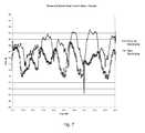
- FIG. 7is a graph comparing measured co-polar F/B performance related to RF signal leakage between conventional band clamp and presently disclosed “new” band clamp configurations.
- FIG. 8is a graph comparing measured cross-polar F/B performance related to RF signal leakage between conventional band clamp and presently disclosed “new” band clamp configurations.
- FIG. 9is a graph of measured co-polar radiation patterns of a 0.6 m reflector antenna with a band clamp with a 1.1 wavelength width.
- FIG. 10is a graph of measured cross-polar radiation patterns of a 0.6 m reflector antenna with a band clamp with a 1.1 wavelength width.
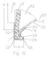
- FIG. 11is an enlarged cut-away side view of a second exemplary radome to reflector dish band clamp interconnection.
- FIG. 12is an enlarged cut-away side view of a third exemplary radome to reflector dish band clamp interconnection, including a width ring.
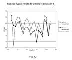
- FIG. 13is a graph comparing predicted F/B enhancement with a band clamp of width of 0.5 and 1.2 wavelengths.
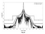
- FIG. 14is a graph of measured co-polar radiation patterns for a reflector antenna with a band clamp with a 0.5 wavelength width.
- FIG. 15is a graph of measured cross-polar radiation patterns for a reflector antenna with a band clamp with a 0.5 wavelength width.
- FIG. 16is a graph of measured co-polar radiation patterns for a reflector antenna with a band clamp with a 1.2 wavelength width.
- FIG. 17is a graph of measured cross-polar radiation patterns for a reflector antenna with a band clamp with a 1.2 wavelength width.
- FIG. 18is an enlarged cut-away side view of a third exemplary radome to reflector dish band clamp interconnection, including a width ring with radial outward bend.
- FIG. 19is a graph comparing predicted F/B enhancement with a band clamp with a width ring configuration of between 0 and 60 degrees radial outward bend.
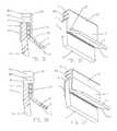
- FIG. 20is an enlarged cut-away view of another exemplary reflector dish band clamp interconnection, including a width ring with a protruding portion aligned parallel to a longitudinal axis of the reflector dish.
- FIG. 21is an isometric view of a section of the band clamp of FIG. 20 .
- FIG. 22is an enlarged cut-away view of another exemplary reflector dish band clamp interconnection, including a width ring with a protruding portion angled at 60 degrees with respect to a longitudinal axis of the reflector dish.
- FIG. 23is an isometric view of the interconnection of FIG. 22 .
- FIG. 24is an enlarged cut-away view of another exemplary reflector dish band clamp interconnection, including a width ring with a protruding portion angled at 60 degrees with respect to a longitudinal axis of the reflector dish, demonstrating a distal edge serration.
- FIG. 25is an isometric view of the interconnection of FIG. 24 .
- FIG. 26is an enlarged cut-away view of another exemplary reflector dish band clamp interconnection, including a width ring with a protruding portion angled at 60 degrees with respect to a longitudinal axis of the reflector dish, demonstrating a distal edge serration and an interference fit against the reflector dish via proximal lip inward bias.
- FIG. 27is an isometric view of the interconnection of FIG. 26 .
- FIG. 28is an enlarged cut-away view of another exemplary reflector dish band clamp interconnection, including a width ring with a protruding portion angled at 60 degrees with respect to a longitudinal axis of the reflector dish, demonstrating a distal edge castellation.
- FIG. 29is an isometric view of the interconnection of FIG. 28 .
- FIG. 30is an enlarged cut-away view of another exemplary reflector dish band clamp interconnection, including a width ring with a protruding portion angled at 60 degrees with respect to a longitudinal axis of the reflector dish, demonstrating an alternative distal edge castellation.
- FIG. 31is an isometric view of the interconnection of FIG. 30 .
- FIG. 32is an enlarged cut-away view of another exemplary reflector dish band clamp interconnection, including a width ring with a protruding portion forming a choke groove open to a distal end of reflector dish.
- FIG. 33is an isometric view of the interconnection of FIG. 32 .
- FIG. 34is an enlarged cut-away view of another exemplary reflector dish band clamp interconnection, including a width ring with a protruding portion forming a choke groove open to a distal end of reflector dish and an annular protrusion of the proximal lip contacting the reflector dish.
- FIG. 35is an isometric view of the interconnection of FIG. 34 .
- FIG. 36is an enlarged cut-away view of another exemplary reflector dish band clamp interconnection, including a width ring with a protruding portion forming two concentric choke grooves open to a distal end of reflector dish.
- FIG. 37is an isometric view of the interconnection of FIG. 36 .
- FIG. 38is an enlarged cut-away view of another exemplary reflector dish band clamp interconnection, including a width ring with a protruding portion forming two concentric choke grooves open to a distal end of reflector dish and interference fit against the reflector dish via proximal lip inward bias.
- FIG. 39is an isometric view of the interconnection of FIG. 38 .
- FIG. 40is an enlarged cut-away view of another exemplary reflector dish band clamp interconnection, including an arc segment transition between the distal lip and the proximal lip.
- FIG. 41is an isometric view of the interconnection of FIG. 40 .
- FIG. 42is an enlarged cut-away view of another exemplary reflector dish band clamp interconnection, including an arc segment transition between the distal lip and the proximal lip and an interference fit against the reflector dish via proximal lip inward bias.
- FIG. 43is an isometric view of the interconnection of FIG. 42 .
- FIG. 44is an enlarged cut-away view of another exemplary reflector dish band clamp interconnection, including a choke groove in the transition between the distal lip and the proximal lip, the choke groove open to the outer diameter.
- FIG. 45is an isometric view of the interconnection of FIG. 44 .
- FIG. 46is an enlarged cut-away view of another exemplary reflector dish band clamp interconnection, including a choke groove in the transition between the distal lip and the proximal lip, the choke groove open to the outer diameter and an interference fit against the reflector dish via proximal lip inward bias.
- FIG. 47is an isometric view of the interconnection of FIG. 46 .
- a band clamp 1is generally operative to retain a radome 3 upon the open distal end 5 of a reflector dish 7 , creating an environmental seal that protects the reflector dish 7 , subreflector 9 and/or feed 11 of a reflector antenna 13 from environmental fouling.
- the band clamp 1is provided with inward facing distal and proximal lips 15 , 17 .
- a turnback region 19 of the proximal lip 17is dimensioned to engage the outer surface 21 of the signal area 23 of the reflector dish 7 .
- the turnback region 19may be applied, for example, as an outward bend prior to the inward end 25 of the proximal lip 17 .
- the diameter of the band clamp 1is progressively reduced, driving the turnback region 19 against the convex outer surface 21 of the signal area 23 of the reflector dish 7 , into a uniform circumferential interference fit.
- the turnback region 19slides progressively inward along the outer surface 21 of the signal area 23 of the reflector dish 7 toward the reflector dish proximal end 27 .
- the distal lip 15 of the band clamp 1also moves towards the reflector dish proximal end 27 , securely clamping the radome 3 against the distal end 5 of the reflector dish 7 . Because the interference fit between the turnback region 19 and the outer surface 21 of the reflector dish 7 is circumferentially uniform, any RF leakage between these surfaces is reduced.
- the radome 3may be provided with a greater diameter than the reflector dish 7 , an annular lip 29 of the radome periphery mating with an outer diameter of the distal end 5 of the reflector dish 7 , keying the radome 3 coaxial with the reflector dish 7 and providing surface area for spacing the band clamp 1 from the signal area 23 of the reflector dish 7 .
- the flangesmay be dimensioned and the band clamp 1 similarly dimensioned such that the distal lip 15 of the band clamp 1 is even with or extends slightly inward of a reflector aperture H, defined as the largest diameter of the reflector dish surface upon which signal energy is distributed by the subreflector 9 , to form a band clamp inner diameter D.
- a reflector aperture Hdefined as the largest diameter of the reflector dish surface upon which signal energy is distributed by the subreflector 9 , to form a band clamp inner diameter D.
- the band clamp inner diameter Dmay be dimensioned with respect to reflector aperture H, resulting in significant F/B enhancement as illustrated in FIG. 5 .
- a D/H ratio of 0.97-1.0may be applied.
- band clamp 1 width “A”determines the distance between band clamp outer corner(s) 31 acting as diffraction/scatter surfaces.
- normalized F/Bis improved when the width “A” is between 0.8 and 1.5 wavelengths of the operating frequency, which can be operative to generate mutual interference of surface currents traveling along the band clamp outer periphery and/or scatter interference.
- FIGS. 7 and 8illustrate measured backlobe levels of co-polar and cross-polar radiation patterns in the 26 GHz band within the regulatory envelopes at greater than 71 dB with the band clamp configuration shown in FIG. 4 , in which the width “A” is equal to 1.1 wavelengths.
- the optimal range of widths “A”may be difficult to achieve for some operating frequencies without incorporating further structure in the radome and/or reflector dish periphery.
- the width “A”may be increased via the application of a fold 33 in the band clamp from the desired extent of the width “A” back toward the reflector dish 7 .
- the pictured embodimentis simplified for demonstration purposes with respect to extending the width “A” but may similarly be applied with a fold 33 and proximal lip 17 that extends further inward and includes a turnback region 19 contacting the outer surface 21 of the signal area 23 of the reflector dish 7 .
- an extension of the width “A”may be cost effectively achieved by attaching a further width ring 35 of metallic and/or metal coated material to the band clamp 1 outer diameter.
- the width ring 35may be applied with any desired width, cost effectively securely attached by spot welding or fasteners such as screws, rivets or the like.
- FIG. 13illustrates 18 GHz band RF modeling software predictions of F/B improvement between a width ring 35 width “A” of 0.5 and 1.2 wavelengths.
- the width ring 35may be provided in an angled configuration as demonstrated in FIG. 18 .
- RF modeling software predictions of F/B improvementindicate progressively increasing improvement as the angle applied increases from zero (flat width ring cross section) to sixty degrees of diffraction gradient.
- structures similar in electrical effect to the width ring 35may be formed integral with the band clamp cross section as a protruding portion 37 of desired dimension.
- These complex structuresmay be cost efficiently formed with high precision via, for example, extrusion, injection molding, progressive punching and/or stretch forming.
- the protruding portion 37creates a band clamp 1 with a generally uniform cross section in which the proximal lip 17 , distal lip 15 and protruding portion 37 form a unitary contiguous portion.
- the unitary contiguous portionsimplifies manufacture by eliminating additional attachment steps and long term interconnection reliability concerns that may arise when separate elements such as width bands 35 are applied to the band clamp 1 .
- the protruding portion 37may be provided extending from an outer diameter of the band clamp 1 parallel to a longitudinal axis of the reflector dish 7 , effectively extending the width “A” of the band clamp 1 without requiring a separate width band 35 as described herein above with respect to FIG. 12 .
- the protruding portion 37may be dimensioned, for example, such that the resulting band width “A” is a multiple of a quarter wavelength of a desired operating frequency of the reflector dish 7 .
- the protruding portion 37may be angled as described hereinabove with respect to FIGS. 18 and 19 . As modeled in FIG. 19 , the angle applied to the protruding portion 37 may be, for example, 60 degrees with respect to a longitudinal axis of the reflector dish 7 .
- the distal edge 39 of the protruding portionmay be provided with a serration 41 ( FIGS. 24-27 ) or a castellation 43 ( FIGS. 28-31 ) to further inhibit backlobe generation at specific operating frequencies.
- Treatments of the distal edge 39 to form the serration(s) 41 and/or castellation 43may be applied as an additional fabrication step upon a uniform cross section band with protruding portion 37 , for example as shown in FIGS. 22 and 23 , by stamping, cutting or the like to remove the desired portions of the distal edge 39 .
- the protruding portion 37may also be dimensioned to extend from the outer diameter of the band clamp 1 to form at least one choke groove 45 open to a distal end 5 of the reflector dish 7 , for example as shown in FIGS. 32-35 .
- the number of choke grooves 45may be increased.
- band clamp 1may be provided with two concentric choke grooves 45 .
- the interference fit between the band clamp 1 and the outer surface 21 of the reflector dish 7may be alternatively obtained by providing the proximal lip 17 with an inward bias, for example as shown in FIGS. 26 , 27 , 34 , 35 , 38 , 39 , 42 , 43 , 46 and 47 .
- the material requirements for the band clamp 1may be reduced in a trade-off with ease of assembly.
- a distal sidewall 47 of the proximal lip 17may be provided with an annular protrusion 49 which contacts the reflector dish 7 , for example as shown in FIGS. 34 and 35 .
- the inward end 25operates as an assembly guide for the band clamp 1 over the reflector dish 7 and radome 3 , prior to engaging the interference fit as the band clamp 1 is inserted far enough for the annular protrusion 49 to enage the reflector dish 7 in the interference fit.
- the band clamp 1may be dimensioned with a transition between the distal lip 15 and the proximal lip 17 formed as a continuous arc segment 51 .
- a material stress applied to the transition to create the bias between the distal lip 15 and the proximal lip 17 against the reflector dish 7may be distributed across a larger portion of material, instead of being concentrated in the outer corners 31 demonstrated in the other embodiments.
- the outer diameter of the band clamp 1(the transition between the distal lip 15 and the proximal lip 17 ) may be provided with a choke groove 45 open to the outer diameter of the band clamp 1 .
- the disclosed band clamp 1can enable significant manufacturing, delivery, installation and/or maintenance efficiencies. Because the band clamp 1 enables simplified radome and reflector dish periphery geometries, the resulting reflector antenna 13 may have improved materials and manufacturing costs. Because the band clamp 1 is simply and securely attached, installation and maintenance may be simplified compared to prior reflector antenna configurations with complex peripheral geometries, delicate back lobe suppression ring coatings, platings and/or RF absorbing materials. Because the band clamp 1 may be compact and applied close to the reflector antenna aperture H, the overall diameter of the reflector antenna 13 may be reduced, which can reduce the reflector antenna wind loading characteristics and the required packaging dimensions.
- band clamp 1is fabricated utilizing extrusion, injection molding, progressive punching and/or stretch forming
- complex band clamp 1 cross sections providing additional electrical performancemay be provided in the form of a protruding portion 37 with specific geometries, without requiring separate elements with additional attachment and/or reliability concerns.
Landscapes
- Physics & Mathematics (AREA)
- Electromagnetism (AREA)
- Aerials With Secondary Devices (AREA)
Abstract
Description
| Table of |
| 1 | |
| 3 | |
| 5 | |
| 7 | |
| 9 | |
| 11 | |
| 13 | |
| 15 | |
| 17 | |
| 19 | |
| 21 | |
| 23 | |
| 25 | |
| 27 | |
| 29 | |
| 31 | |
| 33 | |
| 35 | |
| 37 | protruding |
| 39 | |
| 41 | serration |
| 43 | |
| 45 | |
| 47 | |
| 49 | annular protrusion |
| 51 | arc segment |
Claims (14)
Priority Applications (5)
| Application Number | Priority Date | Filing Date | Title |
|---|---|---|---|
| US13/600,544US9083083B2 (en) | 2009-12-11 | 2012-08-31 | Radome attachment band clamp |
| PCT/US2013/040130WO2014035493A1 (en) | 2012-08-31 | 2013-05-08 | Radome attachment band clamp |
| EP13833558.3AEP2891211B1 (en) | 2012-08-31 | 2013-05-08 | Radome attachment band clamp |
| CN201380044510.2ACN104685711B (en) | 2012-08-31 | 2013-05-08 | Antenna house attachment strip is pressed from both sides |
| BR112015003156-0ABR112015003156B1 (en) | 2012-08-31 | 2013-05-08 | Band-type clamp and method of making a band-type clamp |
Applications Claiming Priority (2)
| Application Number | Priority Date | Filing Date | Title |
|---|---|---|---|
| US12/636,068US8259028B2 (en) | 2009-12-11 | 2009-12-11 | Reflector antenna radome attachment band clamp |
| US13/600,544US9083083B2 (en) | 2009-12-11 | 2012-08-31 | Radome attachment band clamp |
Related Parent Applications (1)
| Application Number | Title | Priority Date | Filing Date |
|---|---|---|---|
| US12/636,068Continuation-In-PartUS8259028B2 (en) | 2009-12-11 | 2009-12-11 | Reflector antenna radome attachment band clamp |
Publications (2)
| Publication Number | Publication Date |
|---|---|
| US20130002515A1 US20130002515A1 (en) | 2013-01-03 |
| US9083083B2true US9083083B2 (en) | 2015-07-14 |
Family
ID=47390106
Family Applications (1)
| Application Number | Title | Priority Date | Filing Date |
|---|---|---|---|
| US13/600,544Active2031-02-01US9083083B2 (en) | 2009-12-11 | 2012-08-31 | Radome attachment band clamp |
Country Status (1)
| Country | Link |
|---|---|
| US (1) | US9083083B2 (en) |
Cited By (140)
| Publication number | Priority date | Publication date | Assignee | Title |
|---|---|---|---|---|
| US20150249281A1 (en)* | 2012-09-24 | 2015-09-03 | Alcatel Lucent | Joining device for fastening a radome onto an antenna reflector |
| US9608740B2 (en) | 2015-07-15 | 2017-03-28 | At&T Intellectual Property I, L.P. | Method and apparatus for launching a wave mode that mitigates interference |
| US9634373B2 (en)* | 2009-06-04 | 2017-04-25 | Ubiquiti Networks, Inc. | Antenna isolation shrouds and reflectors |
| US9640850B2 (en) | 2015-06-25 | 2017-05-02 | At&T Intellectual Property I, L.P. | Methods and apparatus for inducing a non-fundamental wave mode on a transmission medium |
| US9667317B2 (en) | 2015-06-15 | 2017-05-30 | At&T Intellectual Property I, L.P. | Method and apparatus for providing security using network traffic adjustments |
| US9674711B2 (en) | 2013-11-06 | 2017-06-06 | At&T Intellectual Property I, L.P. | Surface-wave communications and methods thereof |
| US9685992B2 (en) | 2014-10-03 | 2017-06-20 | At&T Intellectual Property I, L.P. | Circuit panel network and methods thereof |
| US9705561B2 (en) | 2015-04-24 | 2017-07-11 | At&T Intellectual Property I, L.P. | Directional coupling device and methods for use therewith |
| US9705610B2 (en) | 2014-10-21 | 2017-07-11 | At&T Intellectual Property I, L.P. | Transmission device with impairment compensation and methods for use therewith |
| US9722318B2 (en) | 2015-07-14 | 2017-08-01 | At&T Intellectual Property I, L.P. | Method and apparatus for coupling an antenna to a device |
| US9729197B2 (en) | 2015-10-01 | 2017-08-08 | At&T Intellectual Property I, L.P. | Method and apparatus for communicating network management traffic over a network |
| US9735833B2 (en) | 2015-07-31 | 2017-08-15 | At&T Intellectual Property I, L.P. | Method and apparatus for communications management in a neighborhood network |
| US9742462B2 (en) | 2014-12-04 | 2017-08-22 | At&T Intellectual Property I, L.P. | Transmission medium and communication interfaces and methods for use therewith |
| US9742521B2 (en) | 2014-11-20 | 2017-08-22 | At&T Intellectual Property I, L.P. | Transmission device with mode division multiplexing and methods for use therewith |
| US9749053B2 (en) | 2015-07-23 | 2017-08-29 | At&T Intellectual Property I, L.P. | Node device, repeater and methods for use therewith |
| US9748626B2 (en) | 2015-05-14 | 2017-08-29 | At&T Intellectual Property I, L.P. | Plurality of cables having different cross-sectional shapes which are bundled together to form a transmission medium |
| US9749013B2 (en) | 2015-03-17 | 2017-08-29 | At&T Intellectual Property I, L.P. | Method and apparatus for reducing attenuation of electromagnetic waves guided by a transmission medium |
| US9762289B2 (en) | 2014-10-14 | 2017-09-12 | At&T Intellectual Property I, L.P. | Method and apparatus for transmitting or receiving signals in a transportation system |
| US9769020B2 (en) | 2014-10-21 | 2017-09-19 | At&T Intellectual Property I, L.P. | Method and apparatus for responding to events affecting communications in a communication network |
| US9769128B2 (en) | 2015-09-28 | 2017-09-19 | At&T Intellectual Property I, L.P. | Method and apparatus for encryption of communications over a network |
| US9768833B2 (en) | 2014-09-15 | 2017-09-19 | At&T Intellectual Property I, L.P. | Method and apparatus for sensing a condition in a transmission medium of electromagnetic waves |
| US9780834B2 (en) | 2014-10-21 | 2017-10-03 | At&T Intellectual Property I, L.P. | Method and apparatus for transmitting electromagnetic waves |
| US9787412B2 (en) | 2015-06-25 | 2017-10-10 | At&T Intellectual Property I, L.P. | Methods and apparatus for inducing a fundamental wave mode on a transmission medium |
| US9788326B2 (en) | 2012-12-05 | 2017-10-10 | At&T Intellectual Property I, L.P. | Backhaul link for distributed antenna system |
| US9793954B2 (en) | 2015-04-28 | 2017-10-17 | At&T Intellectual Property I, L.P. | Magnetic coupling device and methods for use therewith |
| US9793951B2 (en) | 2015-07-15 | 2017-10-17 | At&T Intellectual Property I, L.P. | Method and apparatus for launching a wave mode that mitigates interference |
| US9793955B2 (en) | 2015-04-24 | 2017-10-17 | At&T Intellectual Property I, Lp | Passive electrical coupling device and methods for use therewith |
| US9800327B2 (en) | 2014-11-20 | 2017-10-24 | At&T Intellectual Property I, L.P. | Apparatus for controlling operations of a communication device and methods thereof |
| US9820146B2 (en) | 2015-06-12 | 2017-11-14 | At&T Intellectual Property I, L.P. | Method and apparatus for authentication and identity management of communicating devices |
| US9838078B2 (en) | 2015-07-31 | 2017-12-05 | At&T Intellectual Property I, L.P. | Method and apparatus for exchanging communication signals |
| US9838896B1 (en) | 2016-12-09 | 2017-12-05 | At&T Intellectual Property I, L.P. | Method and apparatus for assessing network coverage |
| US9847566B2 (en) | 2015-07-14 | 2017-12-19 | At&T Intellectual Property I, L.P. | Method and apparatus for adjusting a field of a signal to mitigate interference |
| US9847850B2 (en) | 2014-10-14 | 2017-12-19 | At&T Intellectual Property I, L.P. | Method and apparatus for adjusting a mode of communication in a communication network |
| US9853342B2 (en) | 2015-07-14 | 2017-12-26 | At&T Intellectual Property I, L.P. | Dielectric transmission medium connector and methods for use therewith |
| US9860075B1 (en) | 2016-08-26 | 2018-01-02 | At&T Intellectual Property I, L.P. | Method and communication node for broadband distribution |
| US9865911B2 (en) | 2015-06-25 | 2018-01-09 | At&T Intellectual Property I, L.P. | Waveguide system for slot radiating first electromagnetic waves that are combined into a non-fundamental wave mode second electromagnetic wave on a transmission medium |
| US9866276B2 (en) | 2014-10-10 | 2018-01-09 | At&T Intellectual Property I, L.P. | Method and apparatus for arranging communication sessions in a communication system |
| US9866309B2 (en) | 2015-06-03 | 2018-01-09 | At&T Intellectual Property I, Lp | Host node device and methods for use therewith |
| US9871558B2 (en) | 2014-10-21 | 2018-01-16 | At&T Intellectual Property I, L.P. | Guided-wave transmission device and methods for use therewith |
| US9871282B2 (en) | 2015-05-14 | 2018-01-16 | At&T Intellectual Property I, L.P. | At least one transmission medium having a dielectric surface that is covered at least in part by a second dielectric |
| US9871283B2 (en) | 2015-07-23 | 2018-01-16 | At&T Intellectual Property I, Lp | Transmission medium having a dielectric core comprised of plural members connected by a ball and socket configuration |
| US9876264B2 (en) | 2015-10-02 | 2018-01-23 | At&T Intellectual Property I, Lp | Communication system, guided wave switch and methods for use therewith |
| US9876605B1 (en) | 2016-10-21 | 2018-01-23 | At&T Intellectual Property I, L.P. | Launcher and coupling system to support desired guided wave mode |
| US9876570B2 (en) | 2015-02-20 | 2018-01-23 | At&T Intellectual Property I, Lp | Guided-wave transmission device with non-fundamental mode propagation and methods for use therewith |
| US9882257B2 (en) | 2015-07-14 | 2018-01-30 | At&T Intellectual Property I, L.P. | Method and apparatus for launching a wave mode that mitigates interference |
| US9887447B2 (en) | 2015-05-14 | 2018-02-06 | At&T Intellectual Property I, L.P. | Transmission medium having multiple cores and methods for use therewith |
| US9893795B1 (en) | 2016-12-07 | 2018-02-13 | At&T Intellectual Property I, Lp | Method and repeater for broadband distribution |
| US9906269B2 (en) | 2014-09-17 | 2018-02-27 | At&T Intellectual Property I, L.P. | Monitoring and mitigating conditions in a communication network |
| US9912382B2 (en) | 2015-06-03 | 2018-03-06 | At&T Intellectual Property I, Lp | Network termination and methods for use therewith |
| US9913139B2 (en) | 2015-06-09 | 2018-03-06 | At&T Intellectual Property I, L.P. | Signal fingerprinting for authentication of communicating devices |
| US9911020B1 (en) | 2016-12-08 | 2018-03-06 | At&T Intellectual Property I, L.P. | Method and apparatus for tracking via a radio frequency identification device |
| US9912419B1 (en) | 2016-08-24 | 2018-03-06 | At&T Intellectual Property I, L.P. | Method and apparatus for managing a fault in a distributed antenna system |
| US9912033B2 (en) | 2014-10-21 | 2018-03-06 | At&T Intellectual Property I, Lp | Guided wave coupler, coupling module and methods for use therewith |
| US9912027B2 (en) | 2015-07-23 | 2018-03-06 | At&T Intellectual Property I, L.P. | Method and apparatus for exchanging communication signals |
| US9917341B2 (en) | 2015-05-27 | 2018-03-13 | At&T Intellectual Property I, L.P. | Apparatus and method for launching electromagnetic waves and for modifying radial dimensions of the propagating electromagnetic waves |
| US9927517B1 (en) | 2016-12-06 | 2018-03-27 | At&T Intellectual Property I, L.P. | Apparatus and methods for sensing rainfall |
| US9929755B2 (en) | 2015-07-14 | 2018-03-27 | At&T Intellectual Property I, L.P. | Method and apparatus for coupling an antenna to a device |
| US9930668B2 (en) | 2013-05-31 | 2018-03-27 | At&T Intellectual Property I, L.P. | Remote distributed antenna system |
| US9948355B2 (en) | 2014-10-21 | 2018-04-17 | At&T Intellectual Property I, L.P. | Apparatus for providing communication services and methods thereof |
| US9948333B2 (en) | 2015-07-23 | 2018-04-17 | At&T Intellectual Property I, L.P. | Method and apparatus for wireless communications to mitigate interference |
| US9948354B2 (en) | 2015-04-28 | 2018-04-17 | At&T Intellectual Property I, L.P. | Magnetic coupling device with reflective plate and methods for use therewith |
| US9954287B2 (en) | 2014-11-20 | 2018-04-24 | At&T Intellectual Property I, L.P. | Apparatus for converting wireless signals and electromagnetic waves and methods thereof |
| US9954286B2 (en) | 2014-10-21 | 2018-04-24 | At&T Intellectual Property I, L.P. | Guided-wave transmission device with non-fundamental mode propagation and methods for use therewith |
| US9967173B2 (en) | 2015-07-31 | 2018-05-08 | At&T Intellectual Property I, L.P. | Method and apparatus for authentication and identity management of communicating devices |
| US9973940B1 (en) | 2017-02-27 | 2018-05-15 | At&T Intellectual Property I, L.P. | Apparatus and methods for dynamic impedance matching of a guided wave launcher |
| US9973416B2 (en) | 2014-10-02 | 2018-05-15 | At&T Intellectual Property I, L.P. | Method and apparatus that provides fault tolerance in a communication network |
| US9991580B2 (en) | 2016-10-21 | 2018-06-05 | At&T Intellectual Property I, L.P. | Launcher and coupling system for guided wave mode cancellation |
| US9997819B2 (en) | 2015-06-09 | 2018-06-12 | At&T Intellectual Property I, L.P. | Transmission medium and method for facilitating propagation of electromagnetic waves via a core |
| US9999038B2 (en) | 2013-05-31 | 2018-06-12 | At&T Intellectual Property I, L.P. | Remote distributed antenna system |
| US9998870B1 (en) | 2016-12-08 | 2018-06-12 | At&T Intellectual Property I, L.P. | Method and apparatus for proximity sensing |
| US10009063B2 (en) | 2015-09-16 | 2018-06-26 | At&T Intellectual Property I, L.P. | Method and apparatus for use with a radio distributed antenna system having an out-of-band reference signal |
| US10009067B2 (en) | 2014-12-04 | 2018-06-26 | At&T Intellectual Property I, L.P. | Method and apparatus for configuring a communication interface |
| US10020844B2 (en) | 2016-12-06 | 2018-07-10 | T&T Intellectual Property I, L.P. | Method and apparatus for broadcast communication via guided waves |
| US10027398B2 (en) | 2015-06-11 | 2018-07-17 | At&T Intellectual Property I, Lp | Repeater and methods for use therewith |
| US10027397B2 (en) | 2016-12-07 | 2018-07-17 | At&T Intellectual Property I, L.P. | Distributed antenna system and methods for use therewith |
| US10033108B2 (en) | 2015-07-14 | 2018-07-24 | At&T Intellectual Property I, L.P. | Apparatus and methods for generating an electromagnetic wave having a wave mode that mitigates interference |
| US10044409B2 (en) | 2015-07-14 | 2018-08-07 | At&T Intellectual Property I, L.P. | Transmission medium and methods for use therewith |
| US10069535B2 (en) | 2016-12-08 | 2018-09-04 | At&T Intellectual Property I, L.P. | Apparatus and methods for launching electromagnetic waves having a certain electric field structure |
| US10079661B2 (en) | 2015-09-16 | 2018-09-18 | At&T Intellectual Property I, L.P. | Method and apparatus for use with a radio distributed antenna system having a clock reference |
| US10090594B2 (en) | 2016-11-23 | 2018-10-02 | At&T Intellectual Property I, L.P. | Antenna system having structural configurations for assembly |
| US10090606B2 (en) | 2015-07-15 | 2018-10-02 | At&T Intellectual Property I, L.P. | Antenna system with dielectric array and methods for use therewith |
| US10103801B2 (en) | 2015-06-03 | 2018-10-16 | At&T Intellectual Property I, L.P. | Host node device and methods for use therewith |
| US10103422B2 (en) | 2016-12-08 | 2018-10-16 | At&T Intellectual Property I, L.P. | Method and apparatus for mounting network devices |
| US10135145B2 (en) | 2016-12-06 | 2018-11-20 | At&T Intellectual Property I, L.P. | Apparatus and methods for generating an electromagnetic wave along a transmission medium |
| US10135147B2 (en) | 2016-10-18 | 2018-11-20 | At&T Intellectual Property I, L.P. | Apparatus and methods for launching guided waves via an antenna |
| US10135146B2 (en) | 2016-10-18 | 2018-11-20 | At&T Intellectual Property I, L.P. | Apparatus and methods for launching guided waves via circuits |
| US10136434B2 (en) | 2015-09-16 | 2018-11-20 | At&T Intellectual Property I, L.P. | Method and apparatus for use with a radio distributed antenna system having an ultra-wideband control channel |
| US10139820B2 (en) | 2016-12-07 | 2018-11-27 | At&T Intellectual Property I, L.P. | Method and apparatus for deploying equipment of a communication system |
| US10144036B2 (en) | 2015-01-30 | 2018-12-04 | At&T Intellectual Property I, L.P. | Method and apparatus for mitigating interference affecting a propagation of electromagnetic waves guided by a transmission medium |
| US10148016B2 (en) | 2015-07-14 | 2018-12-04 | At&T Intellectual Property I, L.P. | Apparatus and methods for communicating utilizing an antenna array |
| US10168695B2 (en) | 2016-12-07 | 2019-01-01 | At&T Intellectual Property I, L.P. | Method and apparatus for controlling an unmanned aircraft |
| US10170840B2 (en) | 2015-07-14 | 2019-01-01 | At&T Intellectual Property I, L.P. | Apparatus and methods for sending or receiving electromagnetic signals |
| US10178445B2 (en) | 2016-11-23 | 2019-01-08 | At&T Intellectual Property I, L.P. | Methods, devices, and systems for load balancing between a plurality of waveguides |
| US10205655B2 (en) | 2015-07-14 | 2019-02-12 | At&T Intellectual Property I, L.P. | Apparatus and methods for communicating utilizing an antenna array and multiple communication paths |
| US10225025B2 (en) | 2016-11-03 | 2019-03-05 | At&T Intellectual Property I, L.P. | Method and apparatus for detecting a fault in a communication system |
| US10224634B2 (en) | 2016-11-03 | 2019-03-05 | At&T Intellectual Property I, L.P. | Methods and apparatus for adjusting an operational characteristic of an antenna |
| US10243270B2 (en) | 2016-12-07 | 2019-03-26 | At&T Intellectual Property I, L.P. | Beam adaptive multi-feed dielectric antenna system and methods for use therewith |
| US10243784B2 (en) | 2014-11-20 | 2019-03-26 | At&T Intellectual Property I, L.P. | System for generating topology information and methods thereof |
| US10264586B2 (en) | 2016-12-09 | 2019-04-16 | At&T Mobility Ii Llc | Cloud-based packet controller and methods for use therewith |
| US10291334B2 (en) | 2016-11-03 | 2019-05-14 | At&T Intellectual Property I, L.P. | System for detecting a fault in a communication system |
| US10291311B2 (en) | 2016-09-09 | 2019-05-14 | At&T Intellectual Property I, L.P. | Method and apparatus for mitigating a fault in a distributed antenna system |
| US10298293B2 (en) | 2017-03-13 | 2019-05-21 | At&T Intellectual Property I, L.P. | Apparatus of communication utilizing wireless network devices |
| US10305190B2 (en) | 2016-12-01 | 2019-05-28 | At&T Intellectual Property I, L.P. | Reflecting dielectric antenna system and methods for use therewith |
| US10312567B2 (en) | 2016-10-26 | 2019-06-04 | At&T Intellectual Property I, L.P. | Launcher with planar strip antenna and methods for use therewith |
| US10320586B2 (en) | 2015-07-14 | 2019-06-11 | At&T Intellectual Property I, L.P. | Apparatus and methods for generating non-interfering electromagnetic waves on an insulated transmission medium |
| US10326494B2 (en) | 2016-12-06 | 2019-06-18 | At&T Intellectual Property I, L.P. | Apparatus for measurement de-embedding and methods for use therewith |
| US10326689B2 (en) | 2016-12-08 | 2019-06-18 | At&T Intellectual Property I, L.P. | Method and system for providing alternative communication paths |
| US10340601B2 (en) | 2016-11-23 | 2019-07-02 | At&T Intellectual Property I, L.P. | Multi-antenna system and methods for use therewith |
| US10340600B2 (en) | 2016-10-18 | 2019-07-02 | At&T Intellectual Property I, L.P. | Apparatus and methods for launching guided waves via plural waveguide systems |
| US10340603B2 (en) | 2016-11-23 | 2019-07-02 | At&T Intellectual Property I, L.P. | Antenna system having shielded structural configurations for assembly |
| US10340983B2 (en) | 2016-12-09 | 2019-07-02 | At&T Intellectual Property I, L.P. | Method and apparatus for surveying remote sites via guided wave communications |
| US10340573B2 (en) | 2016-10-26 | 2019-07-02 | At&T Intellectual Property I, L.P. | Launcher with cylindrical coupling device and methods for use therewith |
| US10341142B2 (en) | 2015-07-14 | 2019-07-02 | At&T Intellectual Property I, L.P. | Apparatus and methods for generating non-interfering electromagnetic waves on an uninsulated conductor |
| US10355367B2 (en) | 2015-10-16 | 2019-07-16 | At&T Intellectual Property I, L.P. | Antenna structure for exchanging wireless signals |
| US10359749B2 (en) | 2016-12-07 | 2019-07-23 | At&T Intellectual Property I, L.P. | Method and apparatus for utilities management via guided wave communication |
| US10361489B2 (en) | 2016-12-01 | 2019-07-23 | At&T Intellectual Property I, L.P. | Dielectric dish antenna system and methods for use therewith |
| US10374316B2 (en) | 2016-10-21 | 2019-08-06 | At&T Intellectual Property I, L.P. | System and dielectric antenna with non-uniform dielectric |
| US10382976B2 (en) | 2016-12-06 | 2019-08-13 | At&T Intellectual Property I, L.P. | Method and apparatus for managing wireless communications based on communication paths and network device positions |
| US10389037B2 (en) | 2016-12-08 | 2019-08-20 | At&T Intellectual Property I, L.P. | Apparatus and methods for selecting sections of an antenna array and use therewith |
| US10389029B2 (en) | 2016-12-07 | 2019-08-20 | At&T Intellectual Property I, L.P. | Multi-feed dielectric antenna system with core selection and methods for use therewith |
| US10411356B2 (en) | 2016-12-08 | 2019-09-10 | At&T Intellectual Property I, L.P. | Apparatus and methods for selectively targeting communication devices with an antenna array |
| US10439675B2 (en) | 2016-12-06 | 2019-10-08 | At&T Intellectual Property I, L.P. | Method and apparatus for repeating guided wave communication signals |
| US10446936B2 (en) | 2016-12-07 | 2019-10-15 | At&T Intellectual Property I, L.P. | Multi-feed dielectric antenna system and methods for use therewith |
| US10498044B2 (en) | 2016-11-03 | 2019-12-03 | At&T Intellectual Property I, L.P. | Apparatus for configuring a surface of an antenna |
| US10530505B2 (en) | 2016-12-08 | 2020-01-07 | At&T Intellectual Property I, L.P. | Apparatus and methods for launching electromagnetic waves along a transmission medium |
| US10535928B2 (en) | 2016-11-23 | 2020-01-14 | At&T Intellectual Property I, L.P. | Antenna system and methods for use therewith |
| US10547348B2 (en) | 2016-12-07 | 2020-01-28 | At&T Intellectual Property I, L.P. | Method and apparatus for switching transmission mediums in a communication system |
| US10601494B2 (en) | 2016-12-08 | 2020-03-24 | At&T Intellectual Property I, L.P. | Dual-band communication device and method for use therewith |
| US10637149B2 (en) | 2016-12-06 | 2020-04-28 | At&T Intellectual Property I, L.P. | Injection molded dielectric antenna and methods for use therewith |
| US10650940B2 (en) | 2015-05-15 | 2020-05-12 | At&T Intellectual Property I, L.P. | Transmission medium having a conductive material and methods for use therewith |
| US10694379B2 (en) | 2016-12-06 | 2020-06-23 | At&T Intellectual Property I, L.P. | Waveguide system with device-based authentication and methods for use therewith |
| US10727599B2 (en) | 2016-12-06 | 2020-07-28 | At&T Intellectual Property I, L.P. | Launcher with slot antenna and methods for use therewith |
| US10755542B2 (en) | 2016-12-06 | 2020-08-25 | At&T Intellectual Property I, L.P. | Method and apparatus for surveillance via guided wave communication |
| US10777873B2 (en) | 2016-12-08 | 2020-09-15 | At&T Intellectual Property I, L.P. | Method and apparatus for mounting network devices |
| US10797781B2 (en) | 2015-06-03 | 2020-10-06 | At&T Intellectual Property I, L.P. | Client node device and methods for use therewith |
| US10811767B2 (en) | 2016-10-21 | 2020-10-20 | At&T Intellectual Property I, L.P. | System and dielectric antenna with convex dielectric radome |
| US10819035B2 (en) | 2016-12-06 | 2020-10-27 | At&T Intellectual Property I, L.P. | Launcher with helical antenna and methods for use therewith |
| US10916969B2 (en) | 2016-12-08 | 2021-02-09 | At&T Intellectual Property I, L.P. | Method and apparatus for providing power using an inductive coupling |
| US10938108B2 (en) | 2016-12-08 | 2021-03-02 | At&T Intellectual Property I, L.P. | Frequency selective multi-feed dielectric antenna system and methods for use therewith |
| US11032819B2 (en) | 2016-09-15 | 2021-06-08 | At&T Intellectual Property I, L.P. | Method and apparatus for use with a radio distributed antenna system having a control channel reference signal |
Families Citing this family (21)
| Publication number | Priority date | Publication date | Assignee | Title |
|---|---|---|---|---|
| US8836601B2 (en)* | 2013-02-04 | 2014-09-16 | Ubiquiti Networks, Inc. | Dual receiver/transmitter radio devices with choke |
| US9496620B2 (en) | 2013-02-04 | 2016-11-15 | Ubiquiti Networks, Inc. | Radio system for long-range high-speed wireless communication |
| US9543635B2 (en) | 2013-02-04 | 2017-01-10 | Ubiquiti Networks, Inc. | Operation of radio devices for long-range high-speed wireless communication |
| US20160218406A1 (en) | 2013-02-04 | 2016-07-28 | John R. Sanford | Coaxial rf dual-polarized waveguide filter and method |
| US9397820B2 (en) | 2013-02-04 | 2016-07-19 | Ubiquiti Networks, Inc. | Agile duplexing wireless radio devices |
| US9293817B2 (en) | 2013-02-08 | 2016-03-22 | Ubiquiti Networks, Inc. | Stacked array antennas for high-speed wireless communication |
| EP2883276B1 (en)* | 2013-06-27 | 2019-05-22 | CommScope Technologies LLC | Foldable radome |
| PL3648359T3 (en) | 2013-10-11 | 2025-03-31 | Ubiquiti Inc. | Wireless radio system optimization by persistent spectrum analysis |
| US9583822B2 (en) | 2013-10-30 | 2017-02-28 | Commscope Technologies Llc | Broad band radome for microwave antenna |
| US9985347B2 (en) | 2013-10-30 | 2018-05-29 | Commscope Technologies Llc | Broad band radome for microwave antenna |
| WO2015134755A2 (en) | 2014-03-07 | 2015-09-11 | Ubiquiti Networks, Inc. | Devices and methods for networked living and work spaces |
| LT3114884T (en) | 2014-03-07 | 2020-02-10 | Ubiquiti Inc. | IDENTIFICATION AND AUTHENTICATION OF THE CIRCULAR DEVICE |
| US9577323B2 (en)* | 2014-03-07 | 2017-02-21 | Commscope Technologies Llc | Radome—reflector assembly mechanism |
| EP3120642B1 (en) | 2014-03-17 | 2023-06-07 | Ubiquiti Inc. | Array antennas having a plurality of directional beams |
| WO2015153717A1 (en) | 2014-04-01 | 2015-10-08 | Ubiquiti Networks, Inc. | Antenna assembly |
| WO2016003864A1 (en) | 2014-06-30 | 2016-01-07 | Ubiquiti Networks, Inc. | Wireless radio device alignment tools and methods |
| ES2868348T3 (en) | 2014-10-14 | 2021-10-21 | Ubiquiti Inc | Signal isolation covers and reflectors for antenna |
| US10136233B2 (en) | 2015-09-11 | 2018-11-20 | Ubiquiti Networks, Inc. | Compact public address access point apparatuses |
| US10158169B1 (en) | 2017-08-01 | 2018-12-18 | Winegard Company | Mobile antenna system |
| US10770779B2 (en)* | 2018-03-01 | 2020-09-08 | Winegard Company | Stackable antenna enclosure |
| JP7417491B2 (en)* | 2020-07-31 | 2024-01-18 | 株式会社Soken | radar equipment |
Citations (21)
| Publication number | Priority date | Publication date | Assignee | Title |
|---|---|---|---|---|
| US2413187A (en) | 1942-03-06 | 1946-12-24 | Westinghouse Electric Corp | Device for radiation of radio waves |
| US3140491A (en) | 1963-01-24 | 1964-07-07 | Boeing Co | Diffraction shield consisting of notched ring which frames passive reflector |
| US3599219A (en) | 1969-01-29 | 1971-08-10 | Andrew Corp | Backlobe reduction in reflector-type antennas |
| US4410892A (en) | 1981-05-26 | 1983-10-18 | Andrew Corporation | Reflector-type microwave antennas with absorber lined conical feed |
| EP0154240A2 (en) | 1984-02-17 | 1985-09-11 | Comsat Telesystems, Inc. | Satellite tracking antenna system |
| US4581615A (en) | 1983-02-08 | 1986-04-08 | Levy Stanley P | Double reflector antenna with integral radome reflector support |
| US4710777A (en) | 1985-01-24 | 1987-12-01 | Kaultronics, Inc. | Dish antenna structure |
| US4876554A (en) | 1988-01-19 | 1989-10-24 | Qualcomm, Inc. | Pillbox antenna and antenna assembly |
| US4920350A (en) | 1984-02-17 | 1990-04-24 | Comsat Telesystems, Inc. | Satellite tracking antenna system |
| US5298911A (en) | 1990-09-18 | 1994-03-29 | Li Ming Chang | Serrated-roll edge for microwave antennas |
| US5341150A (en) | 1988-09-28 | 1994-08-23 | Georgia Tech Research Corp. | Low sidelobe reflector |
| US5729241A (en) | 1996-05-28 | 1998-03-17 | Ergen; Charles W. | Direct broadcast satellite antenna cover |
| US6137449A (en) | 1996-09-26 | 2000-10-24 | Kildal; Per-Simon | Reflector antenna with a self-supported feed |
| US20010045917A1 (en) | 2000-02-04 | 2001-11-29 | Fedder Ronald L. | Edge guard for a signal receiving device deployably mounted to a vehicle |
| US6339393B1 (en) | 2000-07-20 | 2002-01-15 | The Ohio State University | Rolled edge compact range reflectors |
| US6522305B2 (en) | 2000-02-25 | 2003-02-18 | Andrew Corporation | Microwave antennas |
| US20050099350A1 (en) | 2003-11-07 | 2005-05-12 | Gothard Griffin K. | Multi-band ring focus antenna system with co-located main reflectors |
| US20050190116A1 (en) | 2004-02-27 | 2005-09-01 | Andrew Corporation | Reflector antenna radome with backlobe suppressor ring and method of manufacturing |
| US20070268198A1 (en) | 2006-05-17 | 2007-11-22 | Marshall Dean R | Refractive compact range |
| US20110140983A1 (en) | 2009-12-11 | 2011-06-16 | Andrew Llc | Reflector Antenna Radome Attachment Band Clamp |
| US20130082896A1 (en)* | 2011-09-29 | 2013-04-04 | Andrew Llc | Folded Tab Retention Twin Wall Radome and Method of Manufacture |
- 2012
- 2012-08-31USUS13/600,544patent/US9083083B2/enactiveActive
Patent Citations (24)
| Publication number | Priority date | Publication date | Assignee | Title |
|---|---|---|---|---|
| US2413187A (en) | 1942-03-06 | 1946-12-24 | Westinghouse Electric Corp | Device for radiation of radio waves |
| US3140491A (en) | 1963-01-24 | 1964-07-07 | Boeing Co | Diffraction shield consisting of notched ring which frames passive reflector |
| US3599219A (en) | 1969-01-29 | 1971-08-10 | Andrew Corp | Backlobe reduction in reflector-type antennas |
| US4410892A (en) | 1981-05-26 | 1983-10-18 | Andrew Corporation | Reflector-type microwave antennas with absorber lined conical feed |
| US4410892B1 (en) | 1981-05-26 | 1992-10-13 | Andrew Corp | |
| US4581615A (en) | 1983-02-08 | 1986-04-08 | Levy Stanley P | Double reflector antenna with integral radome reflector support |
| EP0154240A2 (en) | 1984-02-17 | 1985-09-11 | Comsat Telesystems, Inc. | Satellite tracking antenna system |
| US4920350A (en) | 1984-02-17 | 1990-04-24 | Comsat Telesystems, Inc. | Satellite tracking antenna system |
| US4710777A (en) | 1985-01-24 | 1987-12-01 | Kaultronics, Inc. | Dish antenna structure |
| US4876554A (en) | 1988-01-19 | 1989-10-24 | Qualcomm, Inc. | Pillbox antenna and antenna assembly |
| US5341150A (en) | 1988-09-28 | 1994-08-23 | Georgia Tech Research Corp. | Low sidelobe reflector |
| US5298911A (en) | 1990-09-18 | 1994-03-29 | Li Ming Chang | Serrated-roll edge for microwave antennas |
| US5729241A (en) | 1996-05-28 | 1998-03-17 | Ergen; Charles W. | Direct broadcast satellite antenna cover |
| US6137449A (en) | 1996-09-26 | 2000-10-24 | Kildal; Per-Simon | Reflector antenna with a self-supported feed |
| US20010045917A1 (en) | 2000-02-04 | 2001-11-29 | Fedder Ronald L. | Edge guard for a signal receiving device deployably mounted to a vehicle |
| US6522305B2 (en) | 2000-02-25 | 2003-02-18 | Andrew Corporation | Microwave antennas |
| US6339393B1 (en) | 2000-07-20 | 2002-01-15 | The Ohio State University | Rolled edge compact range reflectors |
| US20050099350A1 (en) | 2003-11-07 | 2005-05-12 | Gothard Griffin K. | Multi-band ring focus antenna system with co-located main reflectors |
| US20050190116A1 (en) | 2004-02-27 | 2005-09-01 | Andrew Corporation | Reflector antenna radome with backlobe suppressor ring and method of manufacturing |
| US7138958B2 (en) | 2004-02-27 | 2006-11-21 | Andrew Corporation | Reflector antenna radome with backlobe suppressor ring and method of manufacturing |
| US20070268198A1 (en) | 2006-05-17 | 2007-11-22 | Marshall Dean R | Refractive compact range |
| US20110140983A1 (en) | 2009-12-11 | 2011-06-16 | Andrew Llc | Reflector Antenna Radome Attachment Band Clamp |
| US8259028B2 (en)* | 2009-12-11 | 2012-09-04 | Andrew Llc | Reflector antenna radome attachment band clamp |
| US20130082896A1 (en)* | 2011-09-29 | 2013-04-04 | Andrew Llc | Folded Tab Retention Twin Wall Radome and Method of Manufacture |
Non-Patent Citations (6)
| Title |
|---|
| International Search Report and Written Opinion, International Application serial No. PCT/IB2010/054173, 8 pages, Daejeon, Republic of Korea, Jun. 27, 2011. |
| Kang Sung Chul, International Search Report for Corresponding PCT application PCT/US13/40130, Sep. 23, 2013, Daejeon Metropolitan City, Korea. |
| O. Bucci, C. Gennarelli, L. Palumbo, Flanged Parabolic Antennas, IEEE Transactions on Antennas and Propagation, vol. AP-30, No. 6, p. 1081-1085 Nov. 1982. |
| O. Bucci, C. Gennarelli, L. Palumbo, Parabolic Antennas with a Loaded Flange, IEEE Transactions on Antennas and Propagation, vol. AP-33, No. 7, p. 755-762, Jul. 1985. |
| O. Bucci, G. Di Massa, C. Savarese, Control of Reflector Antennas Performance by Rim Loading, IEEE Transactions on Antennas and Propagation, vol. AP-29, No. 5, p. 773-779 Sep. 1981. |
| O. Bucci, G. Franceschetti, Rim Loaded Reflector Antennas, IEEE Transactions on Antennas and Propagation, vol. AP-28, No. 3, p. 297-305 May 1980. |
Cited By (158)
| Publication number | Priority date | Publication date | Assignee | Title |
|---|---|---|---|---|
| US9634373B2 (en)* | 2009-06-04 | 2017-04-25 | Ubiquiti Networks, Inc. | Antenna isolation shrouds and reflectors |
| US20150249281A1 (en)* | 2012-09-24 | 2015-09-03 | Alcatel Lucent | Joining device for fastening a radome onto an antenna reflector |
| US9768489B2 (en)* | 2012-09-24 | 2017-09-19 | Alcatel Lucent | Joining device for fastening a radome onto an antenna reflector |
| US9788326B2 (en) | 2012-12-05 | 2017-10-10 | At&T Intellectual Property I, L.P. | Backhaul link for distributed antenna system |
| US10091787B2 (en) | 2013-05-31 | 2018-10-02 | At&T Intellectual Property I, L.P. | Remote distributed antenna system |
| US9930668B2 (en) | 2013-05-31 | 2018-03-27 | At&T Intellectual Property I, L.P. | Remote distributed antenna system |
| US10051630B2 (en) | 2013-05-31 | 2018-08-14 | At&T Intellectual Property I, L.P. | Remote distributed antenna system |
| US9999038B2 (en) | 2013-05-31 | 2018-06-12 | At&T Intellectual Property I, L.P. | Remote distributed antenna system |
| US9674711B2 (en) | 2013-11-06 | 2017-06-06 | At&T Intellectual Property I, L.P. | Surface-wave communications and methods thereof |
| US9768833B2 (en) | 2014-09-15 | 2017-09-19 | At&T Intellectual Property I, L.P. | Method and apparatus for sensing a condition in a transmission medium of electromagnetic waves |
| US10063280B2 (en) | 2014-09-17 | 2018-08-28 | At&T Intellectual Property I, L.P. | Monitoring and mitigating conditions in a communication network |
| US9906269B2 (en) | 2014-09-17 | 2018-02-27 | At&T Intellectual Property I, L.P. | Monitoring and mitigating conditions in a communication network |
| US9973416B2 (en) | 2014-10-02 | 2018-05-15 | At&T Intellectual Property I, L.P. | Method and apparatus that provides fault tolerance in a communication network |
| US9685992B2 (en) | 2014-10-03 | 2017-06-20 | At&T Intellectual Property I, L.P. | Circuit panel network and methods thereof |
| US9866276B2 (en) | 2014-10-10 | 2018-01-09 | At&T Intellectual Property I, L.P. | Method and apparatus for arranging communication sessions in a communication system |
| US9762289B2 (en) | 2014-10-14 | 2017-09-12 | At&T Intellectual Property I, L.P. | Method and apparatus for transmitting or receiving signals in a transportation system |
| US9847850B2 (en) | 2014-10-14 | 2017-12-19 | At&T Intellectual Property I, L.P. | Method and apparatus for adjusting a mode of communication in a communication network |
| US9871558B2 (en) | 2014-10-21 | 2018-01-16 | At&T Intellectual Property I, L.P. | Guided-wave transmission device and methods for use therewith |
| US9876587B2 (en) | 2014-10-21 | 2018-01-23 | At&T Intellectual Property I, L.P. | Transmission device with impairment compensation and methods for use therewith |
| US9769020B2 (en) | 2014-10-21 | 2017-09-19 | At&T Intellectual Property I, L.P. | Method and apparatus for responding to events affecting communications in a communication network |
| US9960808B2 (en) | 2014-10-21 | 2018-05-01 | At&T Intellectual Property I, L.P. | Guided-wave transmission device and methods for use therewith |
| US9705610B2 (en) | 2014-10-21 | 2017-07-11 | At&T Intellectual Property I, L.P. | Transmission device with impairment compensation and methods for use therewith |
| US9954286B2 (en) | 2014-10-21 | 2018-04-24 | At&T Intellectual Property I, L.P. | Guided-wave transmission device with non-fundamental mode propagation and methods for use therewith |
| US9780834B2 (en) | 2014-10-21 | 2017-10-03 | At&T Intellectual Property I, L.P. | Method and apparatus for transmitting electromagnetic waves |
| US9912033B2 (en) | 2014-10-21 | 2018-03-06 | At&T Intellectual Property I, Lp | Guided wave coupler, coupling module and methods for use therewith |
| US9948355B2 (en) | 2014-10-21 | 2018-04-17 | At&T Intellectual Property I, L.P. | Apparatus for providing communication services and methods thereof |
| US9800327B2 (en) | 2014-11-20 | 2017-10-24 | At&T Intellectual Property I, L.P. | Apparatus for controlling operations of a communication device and methods thereof |
| US10243784B2 (en) | 2014-11-20 | 2019-03-26 | At&T Intellectual Property I, L.P. | System for generating topology information and methods thereof |
| US9954287B2 (en) | 2014-11-20 | 2018-04-24 | At&T Intellectual Property I, L.P. | Apparatus for converting wireless signals and electromagnetic waves and methods thereof |
| US9742521B2 (en) | 2014-11-20 | 2017-08-22 | At&T Intellectual Property I, L.P. | Transmission device with mode division multiplexing and methods for use therewith |
| US9749083B2 (en) | 2014-11-20 | 2017-08-29 | At&T Intellectual Property I, L.P. | Transmission device with mode division multiplexing and methods for use therewith |
| US10009067B2 (en) | 2014-12-04 | 2018-06-26 | At&T Intellectual Property I, L.P. | Method and apparatus for configuring a communication interface |
| US9742462B2 (en) | 2014-12-04 | 2017-08-22 | At&T Intellectual Property I, L.P. | Transmission medium and communication interfaces and methods for use therewith |
| US10144036B2 (en) | 2015-01-30 | 2018-12-04 | At&T Intellectual Property I, L.P. | Method and apparatus for mitigating interference affecting a propagation of electromagnetic waves guided by a transmission medium |
| US9876570B2 (en) | 2015-02-20 | 2018-01-23 | At&T Intellectual Property I, Lp | Guided-wave transmission device with non-fundamental mode propagation and methods for use therewith |
| US9876571B2 (en) | 2015-02-20 | 2018-01-23 | At&T Intellectual Property I, Lp | Guided-wave transmission device with non-fundamental mode propagation and methods for use therewith |
| US9749013B2 (en) | 2015-03-17 | 2017-08-29 | At&T Intellectual Property I, L.P. | Method and apparatus for reducing attenuation of electromagnetic waves guided by a transmission medium |
| US10224981B2 (en) | 2015-04-24 | 2019-03-05 | At&T Intellectual Property I, Lp | Passive electrical coupling device and methods for use therewith |
| US9831912B2 (en) | 2015-04-24 | 2017-11-28 | At&T Intellectual Property I, Lp | Directional coupling device and methods for use therewith |
| US9705561B2 (en) | 2015-04-24 | 2017-07-11 | At&T Intellectual Property I, L.P. | Directional coupling device and methods for use therewith |
| US9793955B2 (en) | 2015-04-24 | 2017-10-17 | At&T Intellectual Property I, Lp | Passive electrical coupling device and methods for use therewith |
| US9793954B2 (en) | 2015-04-28 | 2017-10-17 | At&T Intellectual Property I, L.P. | Magnetic coupling device and methods for use therewith |
| US9948354B2 (en) | 2015-04-28 | 2018-04-17 | At&T Intellectual Property I, L.P. | Magnetic coupling device with reflective plate and methods for use therewith |
| US9748626B2 (en) | 2015-05-14 | 2017-08-29 | At&T Intellectual Property I, L.P. | Plurality of cables having different cross-sectional shapes which are bundled together to form a transmission medium |
| US9871282B2 (en) | 2015-05-14 | 2018-01-16 | At&T Intellectual Property I, L.P. | At least one transmission medium having a dielectric surface that is covered at least in part by a second dielectric |
| US9887447B2 (en) | 2015-05-14 | 2018-02-06 | At&T Intellectual Property I, L.P. | Transmission medium having multiple cores and methods for use therewith |
| US10650940B2 (en) | 2015-05-15 | 2020-05-12 | At&T Intellectual Property I, L.P. | Transmission medium having a conductive material and methods for use therewith |
| US9917341B2 (en) | 2015-05-27 | 2018-03-13 | At&T Intellectual Property I, L.P. | Apparatus and method for launching electromagnetic waves and for modifying radial dimensions of the propagating electromagnetic waves |
| US9967002B2 (en) | 2015-06-03 | 2018-05-08 | At&T Intellectual I, Lp | Network termination and methods for use therewith |
| US10050697B2 (en) | 2015-06-03 | 2018-08-14 | At&T Intellectual Property I, L.P. | Host node device and methods for use therewith |
| US9935703B2 (en) | 2015-06-03 | 2018-04-03 | At&T Intellectual Property I, L.P. | Host node device and methods for use therewith |
| US9912381B2 (en) | 2015-06-03 | 2018-03-06 | At&T Intellectual Property I, Lp | Network termination and methods for use therewith |
| US9866309B2 (en) | 2015-06-03 | 2018-01-09 | At&T Intellectual Property I, Lp | Host node device and methods for use therewith |
| US10812174B2 (en) | 2015-06-03 | 2020-10-20 | At&T Intellectual Property I, L.P. | Client node device and methods for use therewith |
| US9912382B2 (en) | 2015-06-03 | 2018-03-06 | At&T Intellectual Property I, Lp | Network termination and methods for use therewith |
| US10103801B2 (en) | 2015-06-03 | 2018-10-16 | At&T Intellectual Property I, L.P. | Host node device and methods for use therewith |
| US10797781B2 (en) | 2015-06-03 | 2020-10-06 | At&T Intellectual Property I, L.P. | Client node device and methods for use therewith |
| US9913139B2 (en) | 2015-06-09 | 2018-03-06 | At&T Intellectual Property I, L.P. | Signal fingerprinting for authentication of communicating devices |
| US9997819B2 (en) | 2015-06-09 | 2018-06-12 | At&T Intellectual Property I, L.P. | Transmission medium and method for facilitating propagation of electromagnetic waves via a core |
| US10142010B2 (en) | 2015-06-11 | 2018-11-27 | At&T Intellectual Property I, L.P. | Repeater and methods for use therewith |
| US10027398B2 (en) | 2015-06-11 | 2018-07-17 | At&T Intellectual Property I, Lp | Repeater and methods for use therewith |
| US9820146B2 (en) | 2015-06-12 | 2017-11-14 | At&T Intellectual Property I, L.P. | Method and apparatus for authentication and identity management of communicating devices |
| US9667317B2 (en) | 2015-06-15 | 2017-05-30 | At&T Intellectual Property I, L.P. | Method and apparatus for providing security using network traffic adjustments |
| US9865911B2 (en) | 2015-06-25 | 2018-01-09 | At&T Intellectual Property I, L.P. | Waveguide system for slot radiating first electromagnetic waves that are combined into a non-fundamental wave mode second electromagnetic wave on a transmission medium |
| US9640850B2 (en) | 2015-06-25 | 2017-05-02 | At&T Intellectual Property I, L.P. | Methods and apparatus for inducing a non-fundamental wave mode on a transmission medium |
| US10069185B2 (en) | 2015-06-25 | 2018-09-04 | At&T Intellectual Property I, L.P. | Methods and apparatus for inducing a non-fundamental wave mode on a transmission medium |
| US9787412B2 (en) | 2015-06-25 | 2017-10-10 | At&T Intellectual Property I, L.P. | Methods and apparatus for inducing a fundamental wave mode on a transmission medium |
| US9722318B2 (en) | 2015-07-14 | 2017-08-01 | At&T Intellectual Property I, L.P. | Method and apparatus for coupling an antenna to a device |
| US10148016B2 (en) | 2015-07-14 | 2018-12-04 | At&T Intellectual Property I, L.P. | Apparatus and methods for communicating utilizing an antenna array |
| US10044409B2 (en) | 2015-07-14 | 2018-08-07 | At&T Intellectual Property I, L.P. | Transmission medium and methods for use therewith |
| US10341142B2 (en) | 2015-07-14 | 2019-07-02 | At&T Intellectual Property I, L.P. | Apparatus and methods for generating non-interfering electromagnetic waves on an uninsulated conductor |
| US9882257B2 (en) | 2015-07-14 | 2018-01-30 | At&T Intellectual Property I, L.P. | Method and apparatus for launching a wave mode that mitigates interference |
| US10320586B2 (en) | 2015-07-14 | 2019-06-11 | At&T Intellectual Property I, L.P. | Apparatus and methods for generating non-interfering electromagnetic waves on an insulated transmission medium |
| US9929755B2 (en) | 2015-07-14 | 2018-03-27 | At&T Intellectual Property I, L.P. | Method and apparatus for coupling an antenna to a device |
| US10205655B2 (en) | 2015-07-14 | 2019-02-12 | At&T Intellectual Property I, L.P. | Apparatus and methods for communicating utilizing an antenna array and multiple communication paths |
| US10170840B2 (en) | 2015-07-14 | 2019-01-01 | At&T Intellectual Property I, L.P. | Apparatus and methods for sending or receiving electromagnetic signals |
| US10033108B2 (en) | 2015-07-14 | 2018-07-24 | At&T Intellectual Property I, L.P. | Apparatus and methods for generating an electromagnetic wave having a wave mode that mitigates interference |
| US9847566B2 (en) | 2015-07-14 | 2017-12-19 | At&T Intellectual Property I, L.P. | Method and apparatus for adjusting a field of a signal to mitigate interference |
| US9853342B2 (en) | 2015-07-14 | 2017-12-26 | At&T Intellectual Property I, L.P. | Dielectric transmission medium connector and methods for use therewith |
| US10090606B2 (en) | 2015-07-15 | 2018-10-02 | At&T Intellectual Property I, L.P. | Antenna system with dielectric array and methods for use therewith |
| US9793951B2 (en) | 2015-07-15 | 2017-10-17 | At&T Intellectual Property I, L.P. | Method and apparatus for launching a wave mode that mitigates interference |
| US9608740B2 (en) | 2015-07-15 | 2017-03-28 | At&T Intellectual Property I, L.P. | Method and apparatus for launching a wave mode that mitigates interference |
| US9912027B2 (en) | 2015-07-23 | 2018-03-06 | At&T Intellectual Property I, L.P. | Method and apparatus for exchanging communication signals |
| US9749053B2 (en) | 2015-07-23 | 2017-08-29 | At&T Intellectual Property I, L.P. | Node device, repeater and methods for use therewith |
| US9871283B2 (en) | 2015-07-23 | 2018-01-16 | At&T Intellectual Property I, Lp | Transmission medium having a dielectric core comprised of plural members connected by a ball and socket configuration |
| US9948333B2 (en) | 2015-07-23 | 2018-04-17 | At&T Intellectual Property I, L.P. | Method and apparatus for wireless communications to mitigate interference |
| US9806818B2 (en) | 2015-07-23 | 2017-10-31 | At&T Intellectual Property I, Lp | Node device, repeater and methods for use therewith |
| US9735833B2 (en) | 2015-07-31 | 2017-08-15 | At&T Intellectual Property I, L.P. | Method and apparatus for communications management in a neighborhood network |
| US9838078B2 (en) | 2015-07-31 | 2017-12-05 | At&T Intellectual Property I, L.P. | Method and apparatus for exchanging communication signals |
| US9967173B2 (en) | 2015-07-31 | 2018-05-08 | At&T Intellectual Property I, L.P. | Method and apparatus for authentication and identity management of communicating devices |
| US10136434B2 (en) | 2015-09-16 | 2018-11-20 | At&T Intellectual Property I, L.P. | Method and apparatus for use with a radio distributed antenna system having an ultra-wideband control channel |
| US10079661B2 (en) | 2015-09-16 | 2018-09-18 | At&T Intellectual Property I, L.P. | Method and apparatus for use with a radio distributed antenna system having a clock reference |
| US10009063B2 (en) | 2015-09-16 | 2018-06-26 | At&T Intellectual Property I, L.P. | Method and apparatus for use with a radio distributed antenna system having an out-of-band reference signal |
| US9769128B2 (en) | 2015-09-28 | 2017-09-19 | At&T Intellectual Property I, L.P. | Method and apparatus for encryption of communications over a network |
| US9729197B2 (en) | 2015-10-01 | 2017-08-08 | At&T Intellectual Property I, L.P. | Method and apparatus for communicating network management traffic over a network |
| US9876264B2 (en) | 2015-10-02 | 2018-01-23 | At&T Intellectual Property I, Lp | Communication system, guided wave switch and methods for use therewith |
| US10355367B2 (en) | 2015-10-16 | 2019-07-16 | At&T Intellectual Property I, L.P. | Antenna structure for exchanging wireless signals |
| US9912419B1 (en) | 2016-08-24 | 2018-03-06 | At&T Intellectual Property I, L.P. | Method and apparatus for managing a fault in a distributed antenna system |
| US9860075B1 (en) | 2016-08-26 | 2018-01-02 | At&T Intellectual Property I, L.P. | Method and communication node for broadband distribution |
| US10291311B2 (en) | 2016-09-09 | 2019-05-14 | At&T Intellectual Property I, L.P. | Method and apparatus for mitigating a fault in a distributed antenna system |
| US11032819B2 (en) | 2016-09-15 | 2021-06-08 | At&T Intellectual Property I, L.P. | Method and apparatus for use with a radio distributed antenna system having a control channel reference signal |
| US10135146B2 (en) | 2016-10-18 | 2018-11-20 | At&T Intellectual Property I, L.P. | Apparatus and methods for launching guided waves via circuits |
| US10135147B2 (en) | 2016-10-18 | 2018-11-20 | At&T Intellectual Property I, L.P. | Apparatus and methods for launching guided waves via an antenna |
| US10340600B2 (en) | 2016-10-18 | 2019-07-02 | At&T Intellectual Property I, L.P. | Apparatus and methods for launching guided waves via plural waveguide systems |
| US9876605B1 (en) | 2016-10-21 | 2018-01-23 | At&T Intellectual Property I, L.P. | Launcher and coupling system to support desired guided wave mode |
| US10374316B2 (en) | 2016-10-21 | 2019-08-06 | At&T Intellectual Property I, L.P. | System and dielectric antenna with non-uniform dielectric |
| US9991580B2 (en) | 2016-10-21 | 2018-06-05 | At&T Intellectual Property I, L.P. | Launcher and coupling system for guided wave mode cancellation |
| US10811767B2 (en) | 2016-10-21 | 2020-10-20 | At&T Intellectual Property I, L.P. | System and dielectric antenna with convex dielectric radome |
| US10312567B2 (en) | 2016-10-26 | 2019-06-04 | At&T Intellectual Property I, L.P. | Launcher with planar strip antenna and methods for use therewith |
| US10340573B2 (en) | 2016-10-26 | 2019-07-02 | At&T Intellectual Property I, L.P. | Launcher with cylindrical coupling device and methods for use therewith |
| US10498044B2 (en) | 2016-11-03 | 2019-12-03 | At&T Intellectual Property I, L.P. | Apparatus for configuring a surface of an antenna |
| US10225025B2 (en) | 2016-11-03 | 2019-03-05 | At&T Intellectual Property I, L.P. | Method and apparatus for detecting a fault in a communication system |
| US10224634B2 (en) | 2016-11-03 | 2019-03-05 | At&T Intellectual Property I, L.P. | Methods and apparatus for adjusting an operational characteristic of an antenna |
| US10291334B2 (en) | 2016-11-03 | 2019-05-14 | At&T Intellectual Property I, L.P. | System for detecting a fault in a communication system |
| US10340603B2 (en) | 2016-11-23 | 2019-07-02 | At&T Intellectual Property I, L.P. | Antenna system having shielded structural configurations for assembly |
| US10178445B2 (en) | 2016-11-23 | 2019-01-08 | At&T Intellectual Property I, L.P. | Methods, devices, and systems for load balancing between a plurality of waveguides |
| US10340601B2 (en) | 2016-11-23 | 2019-07-02 | At&T Intellectual Property I, L.P. | Multi-antenna system and methods for use therewith |
| US10090594B2 (en) | 2016-11-23 | 2018-10-02 | At&T Intellectual Property I, L.P. | Antenna system having structural configurations for assembly |
| US10535928B2 (en) | 2016-11-23 | 2020-01-14 | At&T Intellectual Property I, L.P. | Antenna system and methods for use therewith |
| US10361489B2 (en) | 2016-12-01 | 2019-07-23 | At&T Intellectual Property I, L.P. | Dielectric dish antenna system and methods for use therewith |
| US10305190B2 (en) | 2016-12-01 | 2019-05-28 | At&T Intellectual Property I, L.P. | Reflecting dielectric antenna system and methods for use therewith |
| US10326494B2 (en) | 2016-12-06 | 2019-06-18 | At&T Intellectual Property I, L.P. | Apparatus for measurement de-embedding and methods for use therewith |
| US10135145B2 (en) | 2016-12-06 | 2018-11-20 | At&T Intellectual Property I, L.P. | Apparatus and methods for generating an electromagnetic wave along a transmission medium |
| US10819035B2 (en) | 2016-12-06 | 2020-10-27 | At&T Intellectual Property I, L.P. | Launcher with helical antenna and methods for use therewith |
| US9927517B1 (en) | 2016-12-06 | 2018-03-27 | At&T Intellectual Property I, L.P. | Apparatus and methods for sensing rainfall |
| US10755542B2 (en) | 2016-12-06 | 2020-08-25 | At&T Intellectual Property I, L.P. | Method and apparatus for surveillance via guided wave communication |
| US10727599B2 (en) | 2016-12-06 | 2020-07-28 | At&T Intellectual Property I, L.P. | Launcher with slot antenna and methods for use therewith |
| US10694379B2 (en) | 2016-12-06 | 2020-06-23 | At&T Intellectual Property I, L.P. | Waveguide system with device-based authentication and methods for use therewith |
| US10637149B2 (en) | 2016-12-06 | 2020-04-28 | At&T Intellectual Property I, L.P. | Injection molded dielectric antenna and methods for use therewith |
| US10020844B2 (en) | 2016-12-06 | 2018-07-10 | T&T Intellectual Property I, L.P. | Method and apparatus for broadcast communication via guided waves |
| US10439675B2 (en) | 2016-12-06 | 2019-10-08 | At&T Intellectual Property I, L.P. | Method and apparatus for repeating guided wave communication signals |
| US10382976B2 (en) | 2016-12-06 | 2019-08-13 | At&T Intellectual Property I, L.P. | Method and apparatus for managing wireless communications based on communication paths and network device positions |
| US10359749B2 (en) | 2016-12-07 | 2019-07-23 | At&T Intellectual Property I, L.P. | Method and apparatus for utilities management via guided wave communication |
| US10168695B2 (en) | 2016-12-07 | 2019-01-01 | At&T Intellectual Property I, L.P. | Method and apparatus for controlling an unmanned aircraft |
| US10027397B2 (en) | 2016-12-07 | 2018-07-17 | At&T Intellectual Property I, L.P. | Distributed antenna system and methods for use therewith |
| US10243270B2 (en) | 2016-12-07 | 2019-03-26 | At&T Intellectual Property I, L.P. | Beam adaptive multi-feed dielectric antenna system and methods for use therewith |
| US10389029B2 (en) | 2016-12-07 | 2019-08-20 | At&T Intellectual Property I, L.P. | Multi-feed dielectric antenna system with core selection and methods for use therewith |
| US10547348B2 (en) | 2016-12-07 | 2020-01-28 | At&T Intellectual Property I, L.P. | Method and apparatus for switching transmission mediums in a communication system |
| US10139820B2 (en) | 2016-12-07 | 2018-11-27 | At&T Intellectual Property I, L.P. | Method and apparatus for deploying equipment of a communication system |
| US10446936B2 (en) | 2016-12-07 | 2019-10-15 | At&T Intellectual Property I, L.P. | Multi-feed dielectric antenna system and methods for use therewith |
| US9893795B1 (en) | 2016-12-07 | 2018-02-13 | At&T Intellectual Property I, Lp | Method and repeater for broadband distribution |
| US10389037B2 (en) | 2016-12-08 | 2019-08-20 | At&T Intellectual Property I, L.P. | Apparatus and methods for selecting sections of an antenna array and use therewith |
| US10777873B2 (en) | 2016-12-08 | 2020-09-15 | At&T Intellectual Property I, L.P. | Method and apparatus for mounting network devices |
| US10411356B2 (en) | 2016-12-08 | 2019-09-10 | At&T Intellectual Property I, L.P. | Apparatus and methods for selectively targeting communication devices with an antenna array |
| US10601494B2 (en) | 2016-12-08 | 2020-03-24 | At&T Intellectual Property I, L.P. | Dual-band communication device and method for use therewith |
| US10103422B2 (en) | 2016-12-08 | 2018-10-16 | At&T Intellectual Property I, L.P. | Method and apparatus for mounting network devices |
| US9911020B1 (en) | 2016-12-08 | 2018-03-06 | At&T Intellectual Property I, L.P. | Method and apparatus for tracking via a radio frequency identification device |
| US10938108B2 (en) | 2016-12-08 | 2021-03-02 | At&T Intellectual Property I, L.P. | Frequency selective multi-feed dielectric antenna system and methods for use therewith |
| US10916969B2 (en) | 2016-12-08 | 2021-02-09 | At&T Intellectual Property I, L.P. | Method and apparatus for providing power using an inductive coupling |
| US9998870B1 (en) | 2016-12-08 | 2018-06-12 | At&T Intellectual Property I, L.P. | Method and apparatus for proximity sensing |
| US10069535B2 (en) | 2016-12-08 | 2018-09-04 | At&T Intellectual Property I, L.P. | Apparatus and methods for launching electromagnetic waves having a certain electric field structure |
| US10530505B2 (en) | 2016-12-08 | 2020-01-07 | At&T Intellectual Property I, L.P. | Apparatus and methods for launching electromagnetic waves along a transmission medium |
| US10326689B2 (en) | 2016-12-08 | 2019-06-18 | At&T Intellectual Property I, L.P. | Method and system for providing alternative communication paths |
| US10264586B2 (en) | 2016-12-09 | 2019-04-16 | At&T Mobility Ii Llc | Cloud-based packet controller and methods for use therewith |
| US10340983B2 (en) | 2016-12-09 | 2019-07-02 | At&T Intellectual Property I, L.P. | Method and apparatus for surveying remote sites via guided wave communications |
| US9838896B1 (en) | 2016-12-09 | 2017-12-05 | At&T Intellectual Property I, L.P. | Method and apparatus for assessing network coverage |
| US9973940B1 (en) | 2017-02-27 | 2018-05-15 | At&T Intellectual Property I, L.P. | Apparatus and methods for dynamic impedance matching of a guided wave launcher |
| US10298293B2 (en) | 2017-03-13 | 2019-05-21 | At&T Intellectual Property I, L.P. | Apparatus of communication utilizing wireless network devices |
Also Published As
| Publication number | Publication date |
|---|---|
| US20130002515A1 (en) | 2013-01-03 |
Similar Documents
| Publication | Publication Date | Title |
|---|---|---|
| US9083083B2 (en) | Radome attachment band clamp | |
| US8259028B2 (en) | Reflector antenna radome attachment band clamp | |
| US7138958B2 (en) | Reflector antenna radome with backlobe suppressor ring and method of manufacturing | |
| US8077113B2 (en) | Radome and shroud enclosure for reflector antenna | |
| US9019164B2 (en) | Low sidelobe reflector antenna with shield | |
| US8581795B2 (en) | Low sidelobe reflector antenna | |
| US9948009B2 (en) | Controlled illumination dielectric cone radiator for reflector antenna | |
| US10170844B2 (en) | Method for dish reflector illumination via sub-reflector assembly with dielectric radiator portion | |
| US20120287007A1 (en) | Method and Apparatus for Reflector Antenna with Vertex Region Scatter Compensation | |
| US11594822B2 (en) | Parabolic reflector antennas with improved cylindrically-shaped shields | |
| US11075466B2 (en) | Parabolic reflector antennas that support low side lobe radiation patterns | |
| EP2891211B1 (en) | Radome attachment band clamp | |
| WO2014132190A1 (en) | System for fastening a flat radome onto the concave reflector of an antenna |
Legal Events
| Date | Code | Title | Description |
|---|---|---|---|
| AS | Assignment | Owner name:ANDREW LLC, NORTH CAROLINA Free format text:ASSIGNMENT OF ASSIGNORS INTEREST;ASSIGNORS:HILLS, CHRIS;WRIGHT, ALASTAIR D;RENILSON, IAN;REEL/FRAME:028881/0272 Effective date:20120831 | |
| AS | Assignment | Owner name:COMMSCOPE TECHNOLOGIES LLC, NORTH CAROLINA Free format text:CHANGE OF NAME;ASSIGNOR:ANDREW LLC;REEL/FRAME:035176/0585 Effective date:20150301 | |
| STCF | Information on status: patent grant | Free format text:PATENTED CASE | |
| AS | Assignment | Owner name:WILMINGTON TRUST, NATIONAL ASSOCIATION, AS COLLATERAL AGENT, CONNECTICUT Free format text:SECURITY INTEREST;ASSIGNORS:ALLEN TELECOM LLC;COMMSCOPE TECHNOLOGIES LLC;COMMSCOPE, INC. OF NORTH CAROLINA;AND OTHERS;REEL/FRAME:036201/0283 Effective date:20150611 Owner name:WILMINGTON TRUST, NATIONAL ASSOCIATION, AS COLLATE Free format text:SECURITY INTEREST;ASSIGNORS:ALLEN TELECOM LLC;COMMSCOPE TECHNOLOGIES LLC;COMMSCOPE, INC. OF NORTH CAROLINA;AND OTHERS;REEL/FRAME:036201/0283 Effective date:20150611 | |
| AS | Assignment | Owner name:JPMORGAN CHASE BANK, N.A., AS COLLATERAL AGENT, ILLINOIS Free format text:PATENT SECURITY AGREEMENT (TERM);ASSIGNOR:COMMSCOPE TECHNOLOGIES LLC;REEL/FRAME:037513/0709 Effective date:20151220 Owner name:JPMORGAN CHASE BANK, N.A., AS COLLATERAL AGENT, ILLINOIS Free format text:PATENT SECURITY AGREEMENT (ABL);ASSIGNOR:COMMSCOPE TECHNOLOGIES LLC;REEL/FRAME:037514/0196 Effective date:20151220 Owner name:JPMORGAN CHASE BANK, N.A., AS COLLATERAL AGENT, IL Free format text:PATENT SECURITY AGREEMENT (ABL);ASSIGNOR:COMMSCOPE TECHNOLOGIES LLC;REEL/FRAME:037514/0196 Effective date:20151220 Owner name:JPMORGAN CHASE BANK, N.A., AS COLLATERAL AGENT, IL Free format text:PATENT SECURITY AGREEMENT (TERM);ASSIGNOR:COMMSCOPE TECHNOLOGIES LLC;REEL/FRAME:037513/0709 Effective date:20151220 | |
| AS | Assignment | Owner name:REDWOOD SYSTEMS, INC., NORTH CAROLINA Free format text:RELEASE OF SECURITY INTEREST PATENTS (RELEASES RF 036201/0283);ASSIGNOR:WILMINGTON TRUST, NATIONAL ASSOCIATION;REEL/FRAME:042126/0434 Effective date:20170317 Owner name:COMMSCOPE, INC. OF NORTH CAROLINA, NORTH CAROLINA Free format text:RELEASE OF SECURITY INTEREST PATENTS (RELEASES RF 036201/0283);ASSIGNOR:WILMINGTON TRUST, NATIONAL ASSOCIATION;REEL/FRAME:042126/0434 Effective date:20170317 Owner name:COMMSCOPE TECHNOLOGIES LLC, NORTH CAROLINA Free format text:RELEASE OF SECURITY INTEREST PATENTS (RELEASES RF 036201/0283);ASSIGNOR:WILMINGTON TRUST, NATIONAL ASSOCIATION;REEL/FRAME:042126/0434 Effective date:20170317 Owner name:ALLEN TELECOM LLC, NORTH CAROLINA Free format text:RELEASE OF SECURITY INTEREST PATENTS (RELEASES RF 036201/0283);ASSIGNOR:WILMINGTON TRUST, NATIONAL ASSOCIATION;REEL/FRAME:042126/0434 Effective date:20170317 | |
| MAFP | Maintenance fee payment | Free format text:PAYMENT OF MAINTENANCE FEE, 4TH YEAR, LARGE ENTITY (ORIGINAL EVENT CODE: M1551); ENTITY STATUS OF PATENT OWNER: LARGE ENTITY Year of fee payment:4 | |
| AS | Assignment | Owner name:ANDREW LLC, NORTH CAROLINA Free format text:RELEASE BY SECURED PARTY;ASSIGNOR:JPMORGAN CHASE BANK, N.A.;REEL/FRAME:048840/0001 Effective date:20190404 Owner name:ALLEN TELECOM LLC, ILLINOIS Free format text:RELEASE BY SECURED PARTY;ASSIGNOR:JPMORGAN CHASE BANK, N.A.;REEL/FRAME:048840/0001 Effective date:20190404 Owner name:REDWOOD SYSTEMS, INC., NORTH CAROLINA Free format text:RELEASE BY SECURED PARTY;ASSIGNOR:JPMORGAN CHASE BANK, N.A.;REEL/FRAME:048840/0001 Effective date:20190404 Owner name:COMMSCOPE, INC. OF NORTH CAROLINA, NORTH CAROLINA Free format text:RELEASE BY SECURED PARTY;ASSIGNOR:JPMORGAN CHASE BANK, N.A.;REEL/FRAME:048840/0001 Effective date:20190404 Owner name:COMMSCOPE TECHNOLOGIES LLC, NORTH CAROLINA Free format text:RELEASE BY SECURED PARTY;ASSIGNOR:JPMORGAN CHASE BANK, N.A.;REEL/FRAME:048840/0001 Effective date:20190404 Owner name:REDWOOD SYSTEMS, INC., NORTH CAROLINA Free format text:RELEASE BY SECURED PARTY;ASSIGNOR:JPMORGAN CHASE BANK, N.A.;REEL/FRAME:049260/0001 Effective date:20190404 Owner name:COMMSCOPE, INC. OF NORTH CAROLINA, NORTH CAROLINA Free format text:RELEASE BY SECURED PARTY;ASSIGNOR:JPMORGAN CHASE BANK, N.A.;REEL/FRAME:049260/0001 Effective date:20190404 Owner name:ANDREW LLC, NORTH CAROLINA Free format text:RELEASE BY SECURED PARTY;ASSIGNOR:JPMORGAN CHASE BANK, N.A.;REEL/FRAME:049260/0001 Effective date:20190404 Owner name:COMMSCOPE TECHNOLOGIES LLC, NORTH CAROLINA Free format text:RELEASE BY SECURED PARTY;ASSIGNOR:JPMORGAN CHASE BANK, N.A.;REEL/FRAME:049260/0001 Effective date:20190404 Owner name:ALLEN TELECOM LLC, ILLINOIS Free format text:RELEASE BY SECURED PARTY;ASSIGNOR:JPMORGAN CHASE BANK, N.A.;REEL/FRAME:049260/0001 Effective date:20190404 | |
| AS | Assignment | Owner name:WILMINGTON TRUST, NATIONAL ASSOCIATION, AS COLLATE Free format text:PATENT SECURITY AGREEMENT;ASSIGNOR:COMMSCOPE TECHNOLOGIES LLC;REEL/FRAME:049892/0051 Effective date:20190404 Owner name:JPMORGAN CHASE BANK, N.A., NEW YORK Free format text:ABL SECURITY AGREEMENT;ASSIGNORS:COMMSCOPE, INC. OF NORTH CAROLINA;COMMSCOPE TECHNOLOGIES LLC;ARRIS ENTERPRISES LLC;AND OTHERS;REEL/FRAME:049892/0396 Effective date:20190404 Owner name:JPMORGAN CHASE BANK, N.A., NEW YORK Free format text:TERM LOAN SECURITY AGREEMENT;ASSIGNORS:COMMSCOPE, INC. OF NORTH CAROLINA;COMMSCOPE TECHNOLOGIES LLC;ARRIS ENTERPRISES LLC;AND OTHERS;REEL/FRAME:049905/0504 Effective date:20190404 Owner name:WILMINGTON TRUST, NATIONAL ASSOCIATION, AS COLLATERAL AGENT, CONNECTICUT Free format text:PATENT SECURITY AGREEMENT;ASSIGNOR:COMMSCOPE TECHNOLOGIES LLC;REEL/FRAME:049892/0051 Effective date:20190404 | |
| AS | Assignment | Owner name:WILMINGTON TRUST, DELAWARE Free format text:SECURITY INTEREST;ASSIGNORS:ARRIS SOLUTIONS, INC.;ARRIS ENTERPRISES LLC;COMMSCOPE TECHNOLOGIES LLC;AND OTHERS;REEL/FRAME:060752/0001 Effective date:20211115 | |
| MAFP | Maintenance fee payment | Free format text:PAYMENT OF MAINTENANCE FEE, 8TH YEAR, LARGE ENTITY (ORIGINAL EVENT CODE: M1552); ENTITY STATUS OF PATENT OWNER: LARGE ENTITY Year of fee payment:8 | |
| AS | Assignment | Owner name:OUTDOOR WIRELESS NETWORKS LLC, NORTH CAROLINA Free format text:ASSIGNMENT OF ASSIGNORS INTEREST;ASSIGNOR:COMMSCOPE TECHNOLOGIES LLC;REEL/FRAME:068492/0826 Effective date:20240715 | |
| AS | Assignment | Owner name:JPMORGAN CHASE BANK, N.A., AS COLLATERAL AGENT, NEW YORK Free format text:PATENT SECURITY AGREEMENT (TERM);ASSIGNOR:OUTDOOR WIRELESS NETWORKS LLC;REEL/FRAME:068770/0632 Effective date:20240813 Owner name:JPMORGAN CHASE BANK, N.A., AS COLLATERAL AGENT, NEW YORK Free format text:PATENT SECURITY AGREEMENT (ABL);ASSIGNOR:OUTDOOR WIRELESS NETWORKS LLC;REEL/FRAME:068770/0460 Effective date:20240813 | |
| AS | Assignment | Owner name:APOLLO ADMINISTRATIVE AGENCY LLC, NEW YORK Free format text:SECURITY INTEREST;ASSIGNORS:ARRIS ENTERPRISES LLC;COMMSCOPE TECHNOLOGIES LLC;COMMSCOPE INC., OF NORTH CAROLINA;AND OTHERS;REEL/FRAME:069889/0114 Effective date:20241217 | |
| AS | Assignment | Owner name:OUTDOOR WIRELESS NETWORKS LLC, NORTH CAROLINA Free format text:RELEASE OF SECURITY INTEREST AT REEL/FRAME 068770/0632;ASSIGNOR:JPMORGAN CHASE BANK, N.A., AS COLLATERAL AGENT;REEL/FRAME:069743/0264 Effective date:20241217 Owner name:RUCKUS WIRELESS, LLC (F/K/A RUCKUS WIRELESS, INC.), NORTH CAROLINA Free format text:RELEASE OF SECURITY INTEREST AT REEL/FRAME 049905/0504;ASSIGNOR:JPMORGAN CHASE BANK, N.A., AS COLLATERAL AGENT;REEL/FRAME:071477/0255 Effective date:20241217 Owner name:COMMSCOPE TECHNOLOGIES LLC, NORTH CAROLINA Free format text:RELEASE OF SECURITY INTEREST AT REEL/FRAME 049905/0504;ASSIGNOR:JPMORGAN CHASE BANK, N.A., AS COLLATERAL AGENT;REEL/FRAME:071477/0255 Effective date:20241217 Owner name:COMMSCOPE, INC. OF NORTH CAROLINA, NORTH CAROLINA Free format text:RELEASE OF SECURITY INTEREST AT REEL/FRAME 049905/0504;ASSIGNOR:JPMORGAN CHASE BANK, N.A., AS COLLATERAL AGENT;REEL/FRAME:071477/0255 Effective date:20241217 Owner name:ARRIS SOLUTIONS, INC., NORTH CAROLINA Free format text:RELEASE OF SECURITY INTEREST AT REEL/FRAME 049905/0504;ASSIGNOR:JPMORGAN CHASE BANK, N.A., AS COLLATERAL AGENT;REEL/FRAME:071477/0255 Effective date:20241217 Owner name:ARRIS TECHNOLOGY, INC., NORTH CAROLINA Free format text:RELEASE OF SECURITY INTEREST AT REEL/FRAME 049905/0504;ASSIGNOR:JPMORGAN CHASE BANK, N.A., AS COLLATERAL AGENT;REEL/FRAME:071477/0255 Effective date:20241217 Owner name:ARRIS ENTERPRISES LLC (F/K/A ARRIS ENTERPRISES, INC.), NORTH CAROLINA Free format text:RELEASE OF SECURITY INTEREST AT REEL/FRAME 049905/0504;ASSIGNOR:JPMORGAN CHASE BANK, N.A., AS COLLATERAL AGENT;REEL/FRAME:071477/0255 Effective date:20241217 | |
| AS | Assignment | Owner name:OUTDOOR WIRELESS NETWORKS LLC, NORTH CAROLINA Free format text:PARTIAL TERMINATION AND RELEASE OF SECURITY INTEREST IN PATENTS RECORDED AT REEL 069889/FRAME 0114;ASSIGNOR:APOLLO ADMINISTRATIVE AGENCY LLC;REEL/FRAME:070154/0341 Effective date:20250131 Owner name:OUTDOOR WIRELESS NETWORKS LLC, NORTH CAROLINA Free format text:PARTIAL TERMINATION AND RELEASE OF SECURITY INTEREST IN PATENTS;ASSIGNOR:U.S. BANK TRUST COMPANY, NATIONAL ASSOCIATION;REEL/FRAME:070154/0183 Effective date:20250131 Owner name:OUTDOOR WIRELESS NETWORKS LLC, NORTH CAROLINA Free format text:RELEASE (REEL 068770 / FRAME 0460);ASSIGNOR:JPMORGAN CHASE BANK, N.A.;REEL/FRAME:070149/0432 Effective date:20250131 |