US9080827B2 - Robotized arm for a vehicle - Google Patents
Robotized arm for a vehicleDownload PDFInfo
- Publication number
- US9080827B2 US9080827B2US13/115,757US201113115757AUS9080827B2US 9080827 B2US9080827 B2US 9080827B2US 201113115757 AUS201113115757 AUS 201113115757AUS 9080827 B2US9080827 B2US 9080827B2
- Authority
- US
- United States
- Prior art keywords
- fork
- arm
- vehicle
- torsion bar
- armament
- Prior art date
- Legal status (The legal status is an assumption and is not a legal conclusion. Google has not performed a legal analysis and makes no representation as to the accuracy of the status listed.)
- Active
Links
- 230000000284resting effectEffects0.000claimsdescription6
- 238000009434installationMethods0.000claims1
- 230000008901benefitEffects0.000description2
- 238000012544monitoring processMethods0.000description2
- NIOPZPCMRQGZCE-WEVVVXLNSA-N2,4-dinitro-6-(octan-2-yl)phenyl (E)-but-2-enoateChemical compoundCCCCCCC(C)C1=CC([N+]([O-])=O)=CC([N+]([O-])=O)=C1OC(=O)\C=C\CNIOPZPCMRQGZCE-WEVVVXLNSA-N0.000description1
- 230000004913activationEffects0.000description1
- 238000000034methodMethods0.000description1
Images


Classifications
- F—MECHANICAL ENGINEERING; LIGHTING; HEATING; WEAPONS; BLASTING
- F41—WEAPONS
- F41A—FUNCTIONAL FEATURES OR DETAILS COMMON TO BOTH SMALLARMS AND ORDNANCE, e.g. CANNONS; MOUNTINGS FOR SMALLARMS OR ORDNANCE
- F41A23/00—Gun mountings, e.g. on vehicles; Disposition of guns on vehicles
- F41A23/20—Gun mountings, e.g. on vehicles; Disposition of guns on vehicles for disappearing guns
Definitions
- the present inventionrefers to a robotized arm installable on a vehicle.
- the present inventiondescribes a robotized arm installable on a military vehicle provided with an armament positioned on the turret or on the ammunition chest or on the open luggage compartment or caisson of the vehicle.
- the turretis also usually provided with one or more machine guns or armaments in general and with various laying and viewing means or systems, such as for example a day/night stabilized periscopic viewer for the commanding officer, a stabilized viewer with a thermal view and laser telemeter for the gunner, and a fire monitoring computer.
- the fire monitoring computerreceives data from various sensors of the vehicle and is adapted to process all the data for determining the best fire conditions.
- the present inventionsolves this problem providing a robotized arm, upon which it is supported an armament which is adapted to permit the handling and the activation of the armament itself, this arm being installable on a vehicle, for example on the top of the vehicle or on the ammunition chest.
- FIG. 1is a view of the vehicle provided with robotized arm according to the present invention
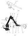
- FIG. 2is a perspective view of the robotized arm according to the present invention.
- FIG. 3is a view of a type of armament which can be supported by the arm of FIG. 2 .
- vehicle 1comprises a conventional passenger compartment 11 , wherein there is the driver and the personnel responsible for the armaments.
- vehicle illustratedis rotated wheeled vehicle, but the present invention can be equivalently applied to a tracked or hybrid vehicle.
- a supporting plate 12On the top of the vehicle there is a supporting plate 12 upon which it is mounted a robotized arm 2 on which free end is supported an armament 3 .
- the supporting platecan be positioned in positions different from the top of the passenger compartment, for example it can be fastened to the loading plane or ammunition chest or on the luggage compartment.
- the arm and the armamentmust be preferably positioned on a dominant position of the vehicle, for permitting the maximum shooting radius to the armament and the best handling of the arm.
- This robotized armis able to permit to this armament to have at least four degrees of freedom in space.
- degrees of freedom in spacerepresent the minimum number for which a robotized arm can support with efficacy the movement of an armament.
- an optimal number of degrees of freedomis six, more preferably seven degrees of freedom.
- FIG. 2an example of embodiment of said robotized arm comprising a resting plate 21 , rotating with respect to said supporting plate 12 about a first vertical axis Y.
- a first fork 22preferably realized in a unique body with the plate, wherein a first sleeve 23 is pivoted, rotating with respect to a first horizontal axis X 1 .
- Said sleeveis integral with respect to one end of a first rod 24 , which, at the opposite end, has an annular support 25 on which a second fork 26 is pivoted, rotating with respect to the annular support about a second horizontal axis X 2 .
- the second fork 26is associated to the first end of a torsion bar 27 , which can turn about its longitudinal axis L 1 with respect to the fork.
- a third fork 28is present, integral with respect to said bar and to which an elongated support 29 for an armament is constrained in an articulated way, which can turn about an axis P perpendicular to longitudinal axis L 1 of the bar.
- this elongated support 29can turn about its longitudinal axis L 2 .
- Armament 3is opportunely constrained to a bracket 291 of said support.
- the robotized armenables the armament to move having a plurality of degrees of freedom, in the specific example the degrees of freedom are six in all, because the armament can move respectively about axis Y, X 1 , X 2 , L 1 , P and L 2 , as shown in FIG. 2 .
- the robotized armcomprises at least a motor duly controlled from inside the vehicle. Furthermore, from inside the vehicle the armament is also completely controlled.
- the robotized armin this way supports the movements of the armament, which can lay also objects not directly visible from the passenger compartment.
- extending the arm and putting rod 24 and bar 27 in a longitudinal position and positioning support 29 such that it is orthogonal with respect to bar 27 itselfit can be created a substantially 90° angulated structure able to lay the armament behind an angle of a building keeping the vehicle hidden.
- the armamentcan be laid further than a wall keeping the vehicle hidden under the wall itself, etc.
- laying and viewing means or systemssuch as for example a day/night stabilized periscopic viewer, or a stabilized viewer with thermal view and laser telemeter which permit to the personnel inside the vehicle to have the view of the zone laid by the armament.
Landscapes
- Engineering & Computer Science (AREA)
- General Engineering & Computer Science (AREA)
- Body Structure For Vehicles (AREA)
- Manipulator (AREA)
- Aiming, Guidance, Guns With A Light Source, Armor, Camouflage, And Targets (AREA)
- Forklifts And Lifting Vehicles (AREA)
Abstract
Description
This application claims benefit of Serial No. TO 2010 A 000440, filed 26 May 2010 in Italy and which application is incorporated herein by reference. To the extent appropriate, a claim of priority is made to the above disclosed application.
The present invention refers to a robotized arm installable on a vehicle.
In particular, the present invention describes a robotized arm installable on a military vehicle provided with an armament positioned on the turret or on the ammunition chest or on the open luggage compartment or caisson of the vehicle.
To the prior art are known armored vehicles movable through a system of tracks or wheeled vehicles provided with a central turret, preferably rotatable upon which is mounted the main armament which is usually constituted by a cannon.
The turret is also usually provided with one or more machine guns or armaments in general and with various laying and viewing means or systems, such as for example a day/night stabilized periscopic viewer for the commanding officer, a stabilized viewer with a thermal view and laser telemeter for the gunner, and a fire monitoring computer. The fire monitoring computer receives data from various sensors of the vehicle and is adapted to process all the data for determining the best fire conditions.
It is clear that these armaments are manually maneuvered by an operator also with the aid of servo-systems which facilitate the handling and laying operations of the armament itself.
The positions of the operator are always protected by shields, walls, or protecting bars, but clearly a risk percentage for the operator is present.
The present invention solves this problem providing a robotized arm, upon which it is supported an armament which is adapted to permit the handling and the activation of the armament itself, this arm being installable on a vehicle, for example on the top of the vehicle or on the ammunition chest.
The characteristics and advantages of the arm according to the present invention will be clearer and evident from the following description, exemplificative and not limiting, of an embodiment with reference to the attached figures wherein:
With reference to the above mentioned figures,vehicle 1 comprises aconventional passenger compartment 11, wherein there is the driver and the personnel responsible for the armaments. In the example of embodiment the vehicle illustrated is rotated wheeled vehicle, but the present invention can be equivalently applied to a tracked or hybrid vehicle.
On the top of the vehicle there is a supportingplate 12 upon which it is mounted a robotizedarm 2 on which free end is supported anarmament 3.
In an alternative embodiment the supporting plate can be positioned in positions different from the top of the passenger compartment, for example it can be fastened to the loading plane or ammunition chest or on the luggage compartment.
In general, the arm and the armament must be preferably positioned on a dominant position of the vehicle, for permitting the maximum shooting radius to the armament and the best handling of the arm.
This robotized arm is able to permit to this armament to have at least four degrees of freedom in space.
Four degrees of freedom in space represent the minimum number for which a robotized arm can support with efficacy the movement of an armament. Preferably, an optimal number of degrees of freedom is six, more preferably seven degrees of freedom.
InFIG. 2 is shown an example of embodiment of said robotized arm comprising aresting plate 21, rotating with respect to said supportingplate 12 about a first vertical axis Y. Upon said restingplate 21 there is afirst fork 22, preferably realized in a unique body with the plate, wherein afirst sleeve 23 is pivoted, rotating with respect to a first horizontal axis X1. Said sleeve is integral with respect to one end of afirst rod 24, which, at the opposite end, has anannular support 25 on which asecond fork 26 is pivoted, rotating with respect to the annular support about a second horizontal axis X2.
Thesecond fork 26 is associated to the first end of atorsion bar 27, which can turn about its longitudinal axis L1 with respect to the fork. At the end of this bar opposite to the one constrained to the second fork athird fork 28 is present, integral with respect to said bar and to which anelongated support 29 for an armament is constrained in an articulated way, which can turn about an axis P perpendicular to longitudinal axis L1 of the bar.
Furthermore, thiselongated support 29 can turn about its longitudinal axis L2.
Clearly, for each degree of freedom, the robotized arm comprises at least a motor duly controlled from inside the vehicle. Furthermore, from inside the vehicle the armament is also completely controlled.
The robotized arm in this way supports the movements of the armament, which can lay also objects not directly visible from the passenger compartment. For example, extending the arm and puttingrod 24 andbar 27 in a longitudinal position and positioningsupport 29 such that it is orthogonal with respect tobar 27 itself, it can be created a substantially 90° angulated structure able to lay the armament behind an angle of a building keeping the vehicle hidden. In another similar configuration, the armament can be laid further than a wall keeping the vehicle hidden under the wall itself, etc.
In these cases, clearly, on the arm can be advantageously provided laying and viewing means or systems, such as for example a day/night stabilized periscopic viewer, or a stabilized viewer with thermal view and laser telemeter which permit to the personnel inside the vehicle to have the view of the zone laid by the armament.
Claims (10)
1. Robotized arm mounted on a supporting plate configured for installation on an upper surface of a vehicle, said vehicle comprising a conventional passenger compartment for housing operators, said robotized arm comprising:
an armament which is supported at the free end of said arm, said robotized arm enabling said armament to have at least six degrees of freedom in space;
a resting plate which rotates said arm with respect to said supporting plate above said vehicle about a first vertical axis;
a first fork on said resting plate;
a first sleeve pivoted on said fork and rotatable with respect to a first horizontal axis;
an elongated first rod having a first end which is integral with said first sleeve;
an annular support on an opposite end of said elongated first rod;
a second fork extending from a torsion bar, the second fork being pivoted on said annular support to rotate about a second horizontal axis with respect to said annular support, said second horizontal axis being maintained parallel to said first horizontal axis;
the torsion bar having a first longitudinal axis and a first end integrally mounted to said second fork; said torsion bar being rotatable about the first longitudinal axis with respect to said second fork and the first longitudinal axis of the torsion bar being maintained perpendicular to the first horizontal axis and the second horizontal axis;
a third fork at an end of said torsion bar which is opposite to the first end of the torsion bar; said third fork being integral with said torsion bar;
an elongated support carrying the armament and constrained in an articulated way to the third fork;
said elongated support having a second longitudinal axis and being able to turn about an axis perpendicular to the longitudinal axis of the torsion bar and being able to turn about the second longitudinal axis;
wherein the arm extends above the vehicle with an unobstructed range of motion about the first vertical axis above the upper surface of said vehicle.
2. The arm according toclaim 1 , wherein the vehicle is a wheeled or tracked vehicle.
3. The arm according toclaim 1 , having laying and viewing systems, which enable the operators within the vehicle to view the area laid at by the armament.
4. The arm according toclaim 1 , wherein said viewing means comprise a stabilized day/night periscopic viewer, or a stabilized viewer with thermal view and laser telemeter.
5. The arm according toclaim 1 , further comprising a motor for each degree of freedom controlled remotely from within the vehicle.
6. The arm according toclaim 1 , wherein the armament is constrained to a bracket of said elongated support.
7. The arm according toclaim 1 , wherein the third fork is integral with the torsion bar.
8. The arm according toclaim 1 , wherein the arm is configured to extend the elongated first rod and the torsion bar in a longitudinal position and positioning the elongated support orthogonally with respect to the torsion bar, with the arm configured as a substantially 90° angulated structure with the armament extending laterally from the vehicle.
9. The arm according toclaim 1 , wherein the first fork defines a first plane perpendicular to the first horizontal axis and wherein the elongated first rod and the torsion bar move within the first plane.
10. A robotized arm and vehicle, the robotized arm being mounted on a supporting plate installed on an upper surface of the vehicle, said vehicle comprising a conventional passenger compartment for housing operators, said robotized arm comprising:
an armament which is supported at the free end of said arm, said robotized arm enabling said armament to have at least six degrees of freedom in space;
a resting plate which rotates said arm with respect to said supporting plate above said vehicle about a first vertical axis;
a first fork on said resting plate;
a first sleeve pivoted on said fork and rotatable with respect to a first horizontal axis;
an elongated first rod having a first end which is integral with said first sleeve;
an annular support on an opposite end of said elongated first rod;
a second fork extending from a torsion bar, the second fork being pivoted on said annular support to rotate about a second horizontal axis with respect to said annular support, said second horizontal axis being maintained parallel to said first horizontal axis;
the torsion bar having a first longitudinal axis and a first end integrally mounted to said second fork; said torsion bar being rotatable about the first longitudinal axis with respect to said second fork and the first longitudinal axis of the torsion bar being maintained perpendicular to the first horizontal axis and the second horizontal axis;
a third fork at an end of said torsion bar which is opposite to the first end of the torsion bar; said third fork being integral with said torsion bar;
an elongated support carrying the armament and constrained in an articulated way to the third fork;
said elongated support having a second longitudinal axis and being able to turn about an axis perpendicular to the longitudinal axis of the torsion bar and being able to turn about the second longitudinal axis;
wherein the arm extends above the vehicle with an unobstructed range of motion about the first vertical axis above said upper surface of said vehicle.
Applications Claiming Priority (3)
| Application Number | Priority Date | Filing Date | Title |
|---|---|---|---|
| ITTO2010A000440 | 2010-05-26 | ||
| ITTO2010A0440 | 2010-05-26 | ||
| ITTO2010A000440AIT1400536B1 (en) | 2010-05-26 | 2010-05-26 | ROBOT ARM FOR A VEHICLE. |
Publications (2)
| Publication Number | Publication Date |
|---|---|
| US20120024142A1 US20120024142A1 (en) | 2012-02-02 |
| US9080827B2true US9080827B2 (en) | 2015-07-14 |
Family
ID=43432076
Family Applications (1)
| Application Number | Title | Priority Date | Filing Date |
|---|---|---|---|
| US13/115,757ActiveUS9080827B2 (en) | 2010-05-26 | 2011-05-25 | Robotized arm for a vehicle |
Country Status (7)
| Country | Link |
|---|---|
| US (1) | US9080827B2 (en) |
| EP (1) | EP2390613B1 (en) |
| CA (1) | CA2741155A1 (en) |
| ES (1) | ES2628140T3 (en) |
| IT (1) | IT1400536B1 (en) |
| PL (1) | PL2390613T3 (en) |
| PT (1) | PT2390613T (en) |
Cited By (4)
| Publication number | Priority date | Publication date | Assignee | Title |
|---|---|---|---|---|
| US20180065192A1 (en)* | 2016-09-06 | 2018-03-08 | Deckel Maho Pfronten Gmbh | Machine tool for machining a workpiece and spindle carrier assembly for use on such a machine tool |
| RU184753U1 (en)* | 2018-06-09 | 2018-11-07 | Акционерное общество "Научно-технический центр ЭЛИНС" | Remote Control Combat Module |
| RU2686896C1 (en)* | 2018-06-09 | 2019-05-06 | Акционерное общество "Научно-технический центр ЭЛИНС" | Combat module with remote control |
| RU2718622C1 (en)* | 2018-06-25 | 2020-04-10 | Открытое акционерное общество "Конструкторское бюро "Дисплей" | Automated remote-controlled observation and fire complex |
Families Citing this family (10)
| Publication number | Priority date | Publication date | Assignee | Title |
|---|---|---|---|---|
| ITTO20120490A1 (en)* | 2012-06-06 | 2013-12-07 | Oto Melara Spa | METALLIC OBJECT DETECTION SYSTEM. |
| RU2531630C1 (en)* | 2013-04-16 | 2014-10-27 | Открытое акционерное общество "Завод им. В.А. Дегтярева" | Combat robot module |
| CN103791776B (en)* | 2014-02-18 | 2015-10-28 | 沈阳陆胜机械有限公司 | Vehicular weapons bracket |
| US10363627B2 (en)* | 2014-12-16 | 2019-07-30 | Illinois Tool Works Inc. | Systems and methods for providing location services for a welding power supply |
| RU2629688C1 (en)* | 2016-02-15 | 2017-08-31 | Открытое акционерное общество "Ковровский электромеханический завод" | Weapon station with remote control |
| US10054400B2 (en)* | 2016-09-14 | 2018-08-21 | Raytheon Company | Robot arm launching system |
| CN107131789B (en)* | 2017-07-11 | 2018-08-07 | 沈阳陆胜机械有限公司 | High stability vehicular weapons bracket |
| RU2723501C1 (en)* | 2019-05-07 | 2020-06-11 | Российская Федерация, от имени которой выступает Министерство обороны Российской Федерации | Combat vehicle control and guidance system |
| US12194575B2 (en) | 2020-01-13 | 2025-01-14 | Milwaukee Electric Tool Corporation | Portable battery pack-powered welder |
| CN114571432B (en)* | 2020-11-30 | 2023-06-20 | 沈阳新松机器人自动化股份有限公司 | Portable dexterous operation arm |
Citations (12)
| Publication number | Priority date | Publication date | Assignee | Title |
|---|---|---|---|---|
| US4785760A (en)* | 1987-01-02 | 1988-11-22 | S A M E S S.A. | Sprayer installation |
| US5430643A (en)* | 1992-03-11 | 1995-07-04 | The United States Of America As Represented By The Administrator Of The National Aeronautics And Space Administration | Configuration control of seven degree of freedom arms |
| US5581166A (en)* | 1986-02-18 | 1996-12-03 | Robotics Research Corporation | Industrial robot with servo |
| US5867631A (en)* | 1995-08-10 | 1999-02-02 | Fujitsu Limited | Manipulator simulation method and apparatus |
| WO2001051259A2 (en) | 2000-01-11 | 2001-07-19 | Hai Hong Zhu | Modular robot manipulator apparatus |
| FR2832792A1 (en) | 2001-11-29 | 2003-05-30 | Giat Ind Sa | Military vehicle observation/firing system having observation unit interfacing vehicle and elevation unit with interface allowing observation unit raising |
| US20050143860A1 (en)* | 2003-12-26 | 2005-06-30 | Japan Aerospace Exploration Agency | Method of controlling redundant manipulator |
| EP1717540A1 (en) | 2005-04-29 | 2006-11-02 | Constructions Industrielles De La Mediterranee- Cnim | Military vehicle provided with a mobile turret |
| US20070119296A1 (en)* | 2004-10-05 | 2007-05-31 | Elbit Systems Ltd. | Multiple weapon system for an armored vehicle |
| US20090044655A1 (en)* | 2007-07-05 | 2009-02-19 | Re2, Inc. | Defense Related Robotic Systems |
| US20090071281A1 (en)* | 2007-09-13 | 2009-03-19 | Fisk Allan T | Robot arm assembly |
| US20100068024A1 (en)* | 2008-09-18 | 2010-03-18 | Agens Michael W | Remotely controlled robots having improved tool deployment systems |
Family Cites Families (49)
| Publication number | Priority date | Publication date | Assignee | Title |
|---|---|---|---|---|
| US3757635A (en) | 1971-03-23 | 1973-09-11 | F Hickerson | Multi-purpose munitions carrier |
| DE2622995A1 (en) | 1976-05-22 | 1977-12-01 | Systemtechnik Gmbh | Elevating chamber for low profile armoured vehicle - has hydraulic extending arm for raising to wide observation and firing position |
| US4062455A (en) | 1976-11-22 | 1977-12-13 | Flatau Carl R | Remote manipulator |
| DE3029294C2 (en) | 1980-08-01 | 1985-03-14 | IBP Pietzsch GmbH, 7505 Ettlingen | Combat vehicle with an extendable platform |
| DE3120338C2 (en) | 1981-05-22 | 1987-04-23 | Eisenwerke Kaiserslautern Entwicklungsgesellschaft mbH, 6750 Kaiserslautern | Combat vehicle |
| US4483407A (en) | 1982-03-26 | 1984-11-20 | Hitachi, Ltd. | Variable configuration track laying vehicle |
| DE3316068A1 (en) | 1983-05-03 | 1984-11-08 | Dr.Ing.H.C. F. Porsche Ag, 7000 Stuttgart | Armoured vehicle |
| EP0178039A3 (en) | 1984-06-15 | 1986-04-30 | Technical Research Products Limited | Disrupter for explosive devices |
| DE3437625A1 (en) | 1984-10-13 | 1986-04-24 | Georg 6200 Wiesbaden Füreder | Variable unit arrangement which can be used independently and/or to support and supply elevating systems |
| DE3440041A1 (en) | 1984-11-02 | 1986-05-07 | Rheinmetall GmbH, 4000 Düsseldorf | HIGH-SWIVEL HEAD Grease for the weapon barrel of a battle tank |
| DE8514264U1 (en) | 1985-05-14 | 1985-08-29 | Otto, Ulrich, 8221 Nußdorf | Stabilized mast shaft for elevatable weapon platform on telescopic arm (e.g. for defense against low-level aircraft) for 3rd generation combat vehicles |
| EP0230720B1 (en) | 1985-10-30 | 1992-01-02 | Evans Deakin Industries Limited | Cable reeling apparatus for a remotely controlled mobile vehicle |
| DE3542787A1 (en) | 1985-12-04 | 1987-06-11 | Jastram Werke | METHOD FOR THE NEUTRALIZATION OF SURFACE-MOUNTED OR CLOTHED LANDMINES AND MOBILE DEVICE FOR IMPLEMENTING THE METHOD |
| EP0262600B1 (en) | 1986-09-29 | 1992-11-25 | Asea Ab | Method and device for optimum parameter control of controllers for rotational and/or linear movements in one or more degrees of freedom in an industrial robot |
| DE3702603A1 (en) | 1987-01-29 | 1988-08-11 | Rheinmetall Gmbh | CHARGING SYSTEM FOR CARTRIDGED AMMUNITION CONTAINERS |
| DE3738835A1 (en) | 1987-11-16 | 1989-05-24 | Srt Steuerungs Regelungstech | Combat vehicle having a weapon platform which can be elevated |
| DE3804445A1 (en) | 1988-02-12 | 1989-08-24 | Krauss Maffei Ag | Lifting device with directional antenna and beam guidance path |
| US4921393A (en) | 1988-03-09 | 1990-05-01 | Sri International | Articulatable structure with adjustable end-point compliance |
| DE3900570A1 (en) | 1989-01-11 | 1990-07-12 | Goeppner Kaiserslautern Eisen | FIGHTING VEHICLE WITH FIGHTING PLATFORMS AND LIFTING SYSTEM |
| DE3931908C2 (en) | 1989-09-25 | 1995-04-27 | Georg Fuereder | Combat vehicle with extendable combat platforms |
| DE3909490A1 (en) | 1989-03-22 | 1990-09-27 | Goeppner Kaiserslautern Eisen | RESET FOR MILITARY COMBAT VEHICLES |
| US5129308A (en) | 1989-03-21 | 1992-07-14 | Fuereder Georg F | Combat vehicle with extendible combat platform |
| US5550953A (en) | 1994-04-20 | 1996-08-27 | The United States Of America As Represented By The Administrator Of The National Aeronautics And Space Administration | On-line method and apparatus for coordinated mobility and manipulation of mobile robots |
| US5443354A (en) | 1992-07-20 | 1995-08-22 | The United States Of America As Represented By The Administrator Of The National Aeronautics And Space Administration | Hazardous materials emergency response mobile robot |
| RU2108532C1 (en) | 1996-05-13 | 1998-04-10 | Голицын Андрей Вячеславович | Combat vehicle |
| SE508533C2 (en) | 1997-02-10 | 1998-10-12 | Asea Brown Boveri | Industrial robot with a turntable electrically isolated from the industrial robot and a method for manufacturing such a robot |
| DE20023572U1 (en) | 1999-06-29 | 2005-01-13 | TDW Gesellschaft für verteidigungstechnische Wirksysteme mbH | Combating explosive bodies, especially mines, involves using platform holding several devices with hollow charges forming projectiles deployed using three-dimensional optical sensor |
| DE10018075A1 (en) | 1999-06-29 | 2001-01-18 | Daimler Chrysler Ag | Combating explosive bodies, especially mines, involves using platform holding several devices with hollow charges forming projectiles deployed using three-dimensional optical sensor |
| DE10132339A1 (en) | 2001-07-04 | 2003-01-16 | Willer Tech Entwicklungen | Landmine detection system comprises detector unit mounted on end of arm attached to tractor, support legs attached to mounting for unit being lowered to support it above ground |
| US8375838B2 (en) | 2001-12-14 | 2013-02-19 | Irobot Corporation | Remote digital firing system |
| ES1056918Y (en) | 2003-08-11 | 2004-09-16 | Corton Vicente Miguel Costero | DEACTIVATION ROBOT OF EXPLOSIVE MINE AND MUNICIPAL ARTS. |
| DE20321807U1 (en) | 2003-08-20 | 2010-05-27 | Kuka Roboter Gmbh | Device for controlling the pressing force of a welding gun |
| US7228778B2 (en) | 2004-04-07 | 2007-06-12 | Terrell Edwards | Recoil reduction adapter |
| JP2005308282A (en) | 2004-04-20 | 2005-11-04 | Komatsu Ltd | Firearm equipment |
| DE102004040253A1 (en) | 2004-08-19 | 2006-03-16 | Diehl Bgt Defence Gmbh & Co. Kg | Modular intelligence-and/or combat system for submarine vehicle, has tank in which robot is provided and rockets and/or missiles are supported, and manipulated with picker arm |
| US20070107917A1 (en) | 2005-11-14 | 2007-05-17 | Doherty Brian J | Multifunctional robot tool |
| DE102005058867B4 (en) | 2005-12-09 | 2018-09-27 | Cine-Tv Broadcast Systems Gmbh | Method and device for moving a camera arranged on a pan and tilt head along a predetermined path of movement |
| US7600460B2 (en) | 2006-05-09 | 2009-10-13 | Stephen M. Manders | On-site land mine removal system |
| US8843244B2 (en) | 2006-10-06 | 2014-09-23 | Irobot Corporation | Autonomous behaviors for a remove vehicle |
| AU2007347733B2 (en) | 2006-10-06 | 2012-05-03 | Irobot Corporation | Robotic vehicle |
| DE102006050941B3 (en) | 2006-10-28 | 2008-07-10 | Diehl Bgt Defence Gmbh & Co. Kg | Controllable agricultural robot |
| CN100551761C (en) | 2006-12-28 | 2009-10-21 | 上海广茂达伙伴机器人有限公司 | Single soldier anti-terrorism robot |
| US20090314883A1 (en) | 2007-05-10 | 2009-12-24 | Arlton Paul E | Uav launch and recovery system |
| WO2009038782A2 (en) | 2007-09-19 | 2009-03-26 | Foster-Miller, Inc. | Operator control unit |
| EP2209595B1 (en) | 2007-10-19 | 2021-09-01 | Force Dimension Technologies Sàrl | Device for movement between an input member and an output member |
| CN201273794Y (en) | 2008-05-22 | 2009-07-15 | 马扬茗 | Motor vehicle equipped with liftable multifunctional electronic collimation weapon station |
| CN101293349A (en) | 2008-06-05 | 2008-10-29 | 广州大学 | A robot based on Wi-Fi |
| DE102008053154A1 (en) | 2008-10-24 | 2010-04-29 | Krauss-Maffei Wegmann Gmbh & Co. Kg | Weapon system, in particular for combat vehicles |
| US20100155156A1 (en) | 2008-11-04 | 2010-06-24 | Robotic Technology Inc. | Energetically autonomous tactical robot and associated methodology of operation |
- 2010
- 2010-05-26ITITTO2010A000440Apatent/IT1400536B1/enactive
- 2011
- 2011-05-20PTPT111668364Tpatent/PT2390613T/enunknown
- 2011-05-20PLPL11166836Tpatent/PL2390613T3/enunknown
- 2011-05-20ESES11166836.4Tpatent/ES2628140T3/enactiveActive
- 2011-05-20EPEP11166836.4Apatent/EP2390613B1/ennot_activeRevoked
- 2011-05-25USUS13/115,757patent/US9080827B2/enactiveActive
- 2011-05-26CACA2741155Apatent/CA2741155A1/ennot_activeAbandoned
Patent Citations (14)
| Publication number | Priority date | Publication date | Assignee | Title |
|---|---|---|---|---|
| US5581166A (en)* | 1986-02-18 | 1996-12-03 | Robotics Research Corporation | Industrial robot with servo |
| US4785760A (en)* | 1987-01-02 | 1988-11-22 | S A M E S S.A. | Sprayer installation |
| US5430643A (en)* | 1992-03-11 | 1995-07-04 | The United States Of America As Represented By The Administrator Of The National Aeronautics And Space Administration | Configuration control of seven degree of freedom arms |
| US5867631A (en)* | 1995-08-10 | 1999-02-02 | Fujitsu Limited | Manipulator simulation method and apparatus |
| WO2001051259A2 (en) | 2000-01-11 | 2001-07-19 | Hai Hong Zhu | Modular robot manipulator apparatus |
| US20050011348A1 (en) | 2001-11-29 | 2005-01-20 | Ludovic Bertrand | Observation and/or firing system |
| FR2832792A1 (en) | 2001-11-29 | 2003-05-30 | Giat Ind Sa | Military vehicle observation/firing system having observation unit interfacing vehicle and elevation unit with interface allowing observation unit raising |
| US20050143860A1 (en)* | 2003-12-26 | 2005-06-30 | Japan Aerospace Exploration Agency | Method of controlling redundant manipulator |
| US20070119296A1 (en)* | 2004-10-05 | 2007-05-31 | Elbit Systems Ltd. | Multiple weapon system for an armored vehicle |
| EP1717540A1 (en) | 2005-04-29 | 2006-11-02 | Constructions Industrielles De La Mediterranee- Cnim | Military vehicle provided with a mobile turret |
| US7624670B2 (en) | 2005-04-29 | 2009-12-01 | Constructions Industrielles De La Mediterranee - Cnim | Military vehicle comprising a swinging arm |
| US20090044655A1 (en)* | 2007-07-05 | 2009-02-19 | Re2, Inc. | Defense Related Robotic Systems |
| US20090071281A1 (en)* | 2007-09-13 | 2009-03-19 | Fisk Allan T | Robot arm assembly |
| US20100068024A1 (en)* | 2008-09-18 | 2010-03-18 | Agens Michael W | Remotely controlled robots having improved tool deployment systems |
Cited By (5)
| Publication number | Priority date | Publication date | Assignee | Title |
|---|---|---|---|---|
| US20180065192A1 (en)* | 2016-09-06 | 2018-03-08 | Deckel Maho Pfronten Gmbh | Machine tool for machining a workpiece and spindle carrier assembly for use on such a machine tool |
| US10518337B2 (en)* | 2016-09-06 | 2019-12-31 | Deckel Maho Pfronten Gmbh | Machine tool for machining a workpiece and spindle carrier assembly for use on such a machine tool |
| RU184753U1 (en)* | 2018-06-09 | 2018-11-07 | Акционерное общество "Научно-технический центр ЭЛИНС" | Remote Control Combat Module |
| RU2686896C1 (en)* | 2018-06-09 | 2019-05-06 | Акционерное общество "Научно-технический центр ЭЛИНС" | Combat module with remote control |
| RU2718622C1 (en)* | 2018-06-25 | 2020-04-10 | Открытое акционерное общество "Конструкторское бюро "Дисплей" | Automated remote-controlled observation and fire complex |
Also Published As
| Publication number | Publication date |
|---|---|
| US20120024142A1 (en) | 2012-02-02 |
| PL2390613T3 (en) | 2017-09-29 |
| IT1400536B1 (en) | 2013-06-11 |
| EP2390613B1 (en) | 2017-03-29 |
| PT2390613T (en) | 2017-06-16 |
| EP2390613A1 (en) | 2011-11-30 |
| ITTO20100440A1 (en) | 2011-11-27 |
| CA2741155A1 (en) | 2011-11-26 |
| ES2628140T3 (en) | 2017-08-01 |
Similar Documents
| Publication | Publication Date | Title |
|---|---|---|
| US9080827B2 (en) | Robotized arm for a vehicle | |
| EP1923657B1 (en) | A compact, fully stabilised, four axes, remote weapon station with independent line of sight | |
| US8459170B2 (en) | Vehicle provided with revolving turret | |
| US8794120B2 (en) | Mortar | |
| CA2795958A1 (en) | Vehicle comprising a turret mount, an auxiliary mount, and a viewing device arranged on the auxiliary mount | |
| US8726783B2 (en) | Turret assembly | |
| JP2014511987A (en) | Vehicle firearm positioning structure | |
| ITMI20060668A1 (en) | AUXILIARY STORAGE DEVICE | |
| RU2647811C1 (en) | Optoelectronic sight with modular body protection | |
| CA2942363C (en) | Military electro-optical sensor tracking | |
| US6733227B2 (en) | Elevating lift | |
| IL223461A (en) | Weapons-based protection device for vehicles | |
| RU2718622C1 (en) | Automated remote-controlled observation and fire complex | |
| EP2354749B1 (en) | Vehicle provided with revolving turret | |
| RU166926U1 (en) | HIDDEN MODULAR FIRE STRUCTURE | |
| KR101930971B1 (en) | Protected embrasure and armoured vehicle thereof | |
| KR101850547B1 (en) | Vehicle provided with revolving turret | |
| RU2027974C1 (en) | Tank | |
| CA2725007C (en) | Vehicle provided with revolving turret | |
| JP5512338B2 (en) | Vehicle equipped with a rotating turret | |
| RU2339897C1 (en) | Minelayer | |
| RU2023116010A (en) | Mobile artillery and rifle system | |
| UA13048U (en) | Method for modernization of object of armoured machinery of the type t-54, t-55, t-62 and t-72 | |
| ITTO20090030A1 (en) | VEHICLE PROVIDED WITH A ROTATING TOWER. | |
| UA24680U (en) | Carriage motor mortar |
Legal Events
| Date | Code | Title | Description |
|---|---|---|---|
| AS | Assignment | Owner name:OTO MELARA S.P.A., ITALY Free format text:ASSIGNMENT OF ASSIGNORS INTEREST;ASSIGNOR:FRANCESCHI, GIULIANO;REEL/FRAME:026347/0659 Effective date:20110418 | |
| STCF | Information on status: patent grant | Free format text:PATENTED CASE | |
| MAFP | Maintenance fee payment | Free format text:PAYMENT OF MAINTENANCE FEE, 4TH YEAR, LARGE ENTITY (ORIGINAL EVENT CODE: M1551); ENTITY STATUS OF PATENT OWNER: LARGE ENTITY Year of fee payment:4 | |
| MAFP | Maintenance fee payment | Free format text:PAYMENT OF MAINTENANCE FEE, 8TH YEAR, LARGE ENTITY (ORIGINAL EVENT CODE: M1552); ENTITY STATUS OF PATENT OWNER: LARGE ENTITY Year of fee payment:8 |