US9078707B2 - Polyaxial facet fixation screw system with cannula inserter - Google Patents
Polyaxial facet fixation screw system with cannula inserterDownload PDFInfo
- Publication number
- US9078707B2 US9078707B2US13/211,807US201113211807AUS9078707B2US 9078707 B2US9078707 B2US 9078707B2US 201113211807 AUS201113211807 AUS 201113211807AUS 9078707 B2US9078707 B2US 9078707B2
- Authority
- US
- United States
- Prior art keywords
- dilator
- cannula
- handle
- instrument
- setting
- Prior art date
- Legal status (The legal status is an assumption and is not a legal conclusion. Google has not performed a legal analysis and makes no representation as to the accuracy of the status listed.)
- Active, expires
Links
- 230000033001locomotionEffects0.000claimsdescription8
- 238000003780insertionMethods0.000abstractdescription12
- 230000037431insertionEffects0.000abstractdescription12
- 238000000034methodMethods0.000abstractdescription6
- 239000007943implantSubstances0.000abstractdescription2
- 210000000988bone and boneAnatomy0.000description18
- 210000002517zygapophyseal jointAnatomy0.000description13
- 239000000463materialSubstances0.000description10
- 238000001356surgical procedureMethods0.000description5
- 210000001519tissueAnatomy0.000description5
- 230000000295complement effectEffects0.000description4
- 230000000399orthopedic effectEffects0.000description4
- RTAQQCXQSZGOHL-UHFFFAOYSA-NTitaniumChemical compound[Ti]RTAQQCXQSZGOHL-UHFFFAOYSA-N0.000description3
- 238000000576coating methodMethods0.000description3
- 238000005516engineering processMethods0.000description3
- 210000004705lumbosacral regionAnatomy0.000description3
- 210000004872soft tissueAnatomy0.000description3
- 229910052719titaniumInorganic materials0.000description3
- 239000010936titaniumSubstances0.000description3
- 0CC1(C*=C)C=CC*1Chemical compoundCC1(C*=C)C=CC*10.000description2
- MCMNRKCIXSYSNV-UHFFFAOYSA-NZirconium dioxideChemical compoundO=[Zr]=OMCMNRKCIXSYSNV-UHFFFAOYSA-N0.000description2
- 229910045601alloyInorganic materials0.000description2
- 239000000956alloySubstances0.000description2
- 239000000919ceramicSubstances0.000description2
- 230000006835compressionEffects0.000description2
- 238000007906compressionMethods0.000description2
- 238000004519manufacturing processMethods0.000description2
- 229910052751metalInorganic materials0.000description2
- 239000002184metalSubstances0.000description2
- 229920000642polymerPolymers0.000description2
- 238000012876topographyMethods0.000description2
- 238000011282treatmentMethods0.000description2
- OKTJSMMVPCPJKN-UHFFFAOYSA-NCarbonChemical compound[C]OKTJSMMVPCPJKN-UHFFFAOYSA-N0.000description1
- 229910000684Cobalt-chromeInorganic materials0.000description1
- 229910000791OxiniumInorganic materials0.000description1
- 229910001069Ti alloyInorganic materials0.000description1
- NRTOMJZYCJJWKI-UHFFFAOYSA-NTitanium nitrideChemical compound[Ti]#NNRTOMJZYCJJWKI-UHFFFAOYSA-N0.000description1
- QCWXUUIWCKQGHC-UHFFFAOYSA-NZirconiumChemical compound[Zr]QCWXUUIWCKQGHC-UHFFFAOYSA-N0.000description1
- 230000009471actionEffects0.000description1
- 230000001154acute effectEffects0.000description1
- 239000000654additiveSubstances0.000description1
- PNEYBMLMFCGWSK-UHFFFAOYSA-Naluminium oxideInorganic materials[O-2].[O-2].[O-2].[Al+3].[Al+3]PNEYBMLMFCGWSK-UHFFFAOYSA-N0.000description1
- 230000000202analgesic effectEffects0.000description1
- 238000004873anchoringMethods0.000description1
- 210000003423ankleAnatomy0.000description1
- 230000003110anti-inflammatory effectEffects0.000description1
- 230000000845anti-microbial effectEffects0.000description1
- 239000004599antimicrobialSubstances0.000description1
- 208000037873arthrodesisDiseases0.000description1
- 230000009286beneficial effectEffects0.000description1
- 230000008901benefitEffects0.000description1
- 239000000560biocompatible materialSubstances0.000description1
- 230000008468bone growthEffects0.000description1
- 229910052799carbonInorganic materials0.000description1
- 238000004140cleaningMethods0.000description1
- 239000011248coating agentSubstances0.000description1
- -1coatingsChemical class0.000description1
- 239000010952cobalt-chromeSubstances0.000description1
- 239000002131composite materialSubstances0.000description1
- 230000001010compromised effectEffects0.000description1
- 229910003460diamondInorganic materials0.000description1
- 239000010432diamondSubstances0.000description1
- 238000009792diffusion processMethods0.000description1
- 230000010339dilationEffects0.000description1
- 239000003814drugSubstances0.000description1
- 230000006870functionEffects0.000description1
- 230000004927fusionEffects0.000description1
- 239000011521glassSubstances0.000description1
- 210000001624hipAnatomy0.000description1
- 238000002513implantationMethods0.000description1
- 238000011065in-situ storageMethods0.000description1
- 238000005468ion implantationMethods0.000description1
- 210000003127kneeAnatomy0.000description1
- 210000003041ligamentAnatomy0.000description1
- 230000000670limiting effectEffects0.000description1
- 230000007246mechanismEffects0.000description1
- 150000002739metalsChemical class0.000description1
- 230000005012migrationEffects0.000description1
- 238000013508migrationMethods0.000description1
- 210000003205muscleAnatomy0.000description1
- 229910052758niobiumInorganic materials0.000description1
- 239000010955niobiumSubstances0.000description1
- GUCVJGMIXFAOAE-UHFFFAOYSA-Nniobium atomChemical compound[Nb]GUCVJGMIXFAOAE-UHFFFAOYSA-N0.000description1
- 238000004806packaging method and processMethods0.000description1
- 230000036961partial effectEffects0.000description1
- 230000002093peripheral effectEffects0.000description1
- 230000002265preventionEffects0.000description1
- 230000008569processEffects0.000description1
- 230000000284resting effectEffects0.000description1
- 230000000717retained effectEffects0.000description1
- 238000007788rougheningMethods0.000description1
- 210000002832shoulderAnatomy0.000description1
- 229910001220stainless steelInorganic materials0.000description1
- 239000010935stainless steelSubstances0.000description1
- 238000004381surface treatmentMethods0.000description1
- 210000002435tendonAnatomy0.000description1
- 229940124597therapeutic agentDrugs0.000description1
- MTPVUVINMAGMJL-UHFFFAOYSA-Ntrimethyl(1,1,2,2,2-pentafluoroethyl)silaneChemical compoundC[Si](C)(C)C(F)(F)C(F)(F)FMTPVUVINMAGMJL-UHFFFAOYSA-N0.000description1
- 238000003466weldingMethods0.000description1
- 239000002023woodSubstances0.000description1
- 210000000707wristAnatomy0.000description1
- 229910052726zirconiumInorganic materials0.000description1
- ZVWKZXLXHLZXLS-UHFFFAOYSA-Nzirconium nitrideChemical compound[Zr]#NZVWKZXLXHLZXLS-UHFFFAOYSA-N0.000description1
Images


Classifications
- A—HUMAN NECESSITIES
- A61—MEDICAL OR VETERINARY SCIENCE; HYGIENE
- A61B—DIAGNOSIS; SURGERY; IDENTIFICATION
- A61B17/00—Surgical instruments, devices or methods
- A61B17/56—Surgical instruments or methods for treatment of bones or joints; Devices specially adapted therefor
- A61B17/58—Surgical instruments or methods for treatment of bones or joints; Devices specially adapted therefor for osteosynthesis, e.g. bone plates, screws or setting implements
- A61B17/68—Internal fixation devices, including fasteners and spinal fixators, even if a part thereof projects from the skin
- A61B17/70—Spinal positioners or stabilisers, e.g. stabilisers comprising fluid filler in an implant
- A61B17/7062—Devices acting on, attached to, or simulating the effect of, vertebral processes, vertebral facets or ribs ; Tools for such devices
- A61B17/7064—Devices acting on, attached to, or simulating the effect of, vertebral facets; Tools therefor
- A—HUMAN NECESSITIES
- A61—MEDICAL OR VETERINARY SCIENCE; HYGIENE
- A61B—DIAGNOSIS; SURGERY; IDENTIFICATION
- A61B1/00—Instruments for performing medical examinations of the interior of cavities or tubes of the body by visual or photographical inspection, e.g. endoscopes; Illuminating arrangements therefor
- A61B1/32—Devices for opening or enlarging the visual field, e.g. of a tube of the body
- A—HUMAN NECESSITIES
- A61—MEDICAL OR VETERINARY SCIENCE; HYGIENE
- A61B—DIAGNOSIS; SURGERY; IDENTIFICATION
- A61B17/00—Surgical instruments, devices or methods
- A61B17/34—Trocars; Puncturing needles
- A61B17/3417—Details of tips or shafts, e.g. grooves, expandable, bendable; Multiple coaxial sliding cannulas, e.g. for dilating
- A61B17/3421—Cannulas
- A—HUMAN NECESSITIES
- A61—MEDICAL OR VETERINARY SCIENCE; HYGIENE
- A61B—DIAGNOSIS; SURGERY; IDENTIFICATION
- A61B17/00—Surgical instruments, devices or methods
- A61B17/56—Surgical instruments or methods for treatment of bones or joints; Devices specially adapted therefor
- A61B17/58—Surgical instruments or methods for treatment of bones or joints; Devices specially adapted therefor for osteosynthesis, e.g. bone plates, screws or setting implements
- A61B17/68—Internal fixation devices, including fasteners and spinal fixators, even if a part thereof projects from the skin
- A61B17/70—Spinal positioners or stabilisers, e.g. stabilisers comprising fluid filler in an implant
- A61B17/7062—Devices acting on, attached to, or simulating the effect of, vertebral processes, vertebral facets or ribs ; Tools for such devices
- A61B17/7065—Devices with changeable shape, e.g. collapsible or having retractable arms to aid implantation; Tools therefor
- A—HUMAN NECESSITIES
- A61—MEDICAL OR VETERINARY SCIENCE; HYGIENE
- A61B—DIAGNOSIS; SURGERY; IDENTIFICATION
- A61B17/00—Surgical instruments, devices or methods
- A61B17/56—Surgical instruments or methods for treatment of bones or joints; Devices specially adapted therefor
- A61B17/58—Surgical instruments or methods for treatment of bones or joints; Devices specially adapted therefor for osteosynthesis, e.g. bone plates, screws or setting implements
- A61B17/68—Internal fixation devices, including fasteners and spinal fixators, even if a part thereof projects from the skin
- A61B17/70—Spinal positioners or stabilisers, e.g. stabilisers comprising fluid filler in an implant
- A61B17/7074—Tools specially adapted for spinal fixation operations other than for bone removal or filler handling
- A61B17/7076—Tools specially adapted for spinal fixation operations other than for bone removal or filler handling for driving, positioning or assembling spinal clamps or bone anchors specially adapted for spinal fixation
- A—HUMAN NECESSITIES
- A61—MEDICAL OR VETERINARY SCIENCE; HYGIENE
- A61B—DIAGNOSIS; SURGERY; IDENTIFICATION
- A61B17/00—Surgical instruments, devices or methods
- A61B17/34—Trocars; Puncturing needles
- A61B17/3468—Trocars; Puncturing needles for implanting or removing devices, e.g. prostheses, implants, seeds, wires
- A—HUMAN NECESSITIES
- A61—MEDICAL OR VETERINARY SCIENCE; HYGIENE
- A61B—DIAGNOSIS; SURGERY; IDENTIFICATION
- A61B17/00—Surgical instruments, devices or methods
- A61B17/56—Surgical instruments or methods for treatment of bones or joints; Devices specially adapted therefor
- A61B17/58—Surgical instruments or methods for treatment of bones or joints; Devices specially adapted therefor for osteosynthesis, e.g. bone plates, screws or setting implements
- A61B17/68—Internal fixation devices, including fasteners and spinal fixators, even if a part thereof projects from the skin
- A61B17/686—Plugs, i.e. elements forming interface between bone hole and implant or fastener, e.g. screw
- A—HUMAN NECESSITIES
- A61—MEDICAL OR VETERINARY SCIENCE; HYGIENE
- A61B—DIAGNOSIS; SURGERY; IDENTIFICATION
- A61B17/00—Surgical instruments, devices or methods
- A61B17/56—Surgical instruments or methods for treatment of bones or joints; Devices specially adapted therefor
- A61B17/58—Surgical instruments or methods for treatment of bones or joints; Devices specially adapted therefor for osteosynthesis, e.g. bone plates, screws or setting implements
- A61B17/68—Internal fixation devices, including fasteners and spinal fixators, even if a part thereof projects from the skin
- A61B17/84—Fasteners therefor or fasteners being internal fixation devices
- A61B17/86—Pins or screws or threaded wires; nuts therefor
- A61B17/8685—Pins or screws or threaded wires; nuts therefor comprising multiple separate parts
- A—HUMAN NECESSITIES
- A61—MEDICAL OR VETERINARY SCIENCE; HYGIENE
- A61B—DIAGNOSIS; SURGERY; IDENTIFICATION
- A61B17/00—Surgical instruments, devices or methods
- A61B17/56—Surgical instruments or methods for treatment of bones or joints; Devices specially adapted therefor
- A61B17/58—Surgical instruments or methods for treatment of bones or joints; Devices specially adapted therefor for osteosynthesis, e.g. bone plates, screws or setting implements
- A61B17/68—Internal fixation devices, including fasteners and spinal fixators, even if a part thereof projects from the skin
- A61B17/84—Fasteners therefor or fasteners being internal fixation devices
- A61B17/86—Pins or screws or threaded wires; nuts therefor
- A61B17/8695—Washers
- A—HUMAN NECESSITIES
- A61—MEDICAL OR VETERINARY SCIENCE; HYGIENE
- A61B—DIAGNOSIS; SURGERY; IDENTIFICATION
- A61B17/00—Surgical instruments, devices or methods
- A61B2017/0023—Surgical instruments, devices or methods disposable
- A—HUMAN NECESSITIES
- A61—MEDICAL OR VETERINARY SCIENCE; HYGIENE
- A61B—DIAGNOSIS; SURGERY; IDENTIFICATION
- A61B17/00—Surgical instruments, devices or methods
- A61B2017/0042—Surgical instruments, devices or methods with special provisions for gripping
- A61B2017/00424—Surgical instruments, devices or methods with special provisions for gripping ergonomic, e.g. fitting in fist
- A—HUMAN NECESSITIES
- A61—MEDICAL OR VETERINARY SCIENCE; HYGIENE
- A61B—DIAGNOSIS; SURGERY; IDENTIFICATION
- A61B17/00—Surgical instruments, devices or methods
- A61B2017/0046—Surgical instruments, devices or methods with a releasable handle; with handle and operating part separable
- A—HUMAN NECESSITIES
- A61—MEDICAL OR VETERINARY SCIENCE; HYGIENE
- A61B—DIAGNOSIS; SURGERY; IDENTIFICATION
- A61B17/00—Surgical instruments, devices or methods
- A61B17/02—Surgical instruments, devices or methods for holding wounds open, e.g. retractors; Tractors
- A61B17/025—Joint distractors
- A61B2017/0256—Joint distractors for the spine
- A—HUMAN NECESSITIES
- A61—MEDICAL OR VETERINARY SCIENCE; HYGIENE
- A61B—DIAGNOSIS; SURGERY; IDENTIFICATION
- A61B17/00—Surgical instruments, devices or methods
- A61B17/34—Trocars; Puncturing needles
- A61B2017/347—Locking means, e.g. for locking instrument in cannula
- A—HUMAN NECESSITIES
- A61—MEDICAL OR VETERINARY SCIENCE; HYGIENE
- A61B—DIAGNOSIS; SURGERY; IDENTIFICATION
- A61B17/00—Surgical instruments, devices or methods
- A61B17/56—Surgical instruments or methods for treatment of bones or joints; Devices specially adapted therefor
- A61B17/58—Surgical instruments or methods for treatment of bones or joints; Devices specially adapted therefor for osteosynthesis, e.g. bone plates, screws or setting implements
- A61B17/68—Internal fixation devices, including fasteners and spinal fixators, even if a part thereof projects from the skin
- A61B17/84—Fasteners therefor or fasteners being internal fixation devices
- A61B17/86—Pins or screws or threaded wires; nuts therefor
- A61B2017/8655—Pins or screws or threaded wires; nuts therefor with special features for locking in the bone
- A61B2019/462—
- A—HUMAN NECESSITIES
- A61—MEDICAL OR VETERINARY SCIENCE; HYGIENE
- A61B—DIAGNOSIS; SURGERY; IDENTIFICATION
- A61B90/00—Instruments, implements or accessories specially adapted for surgery or diagnosis and not covered by any of the groups A61B1/00 - A61B50/00, e.g. for luxation treatment or for protecting wound edges
- A61B90/06—Measuring instruments not otherwise provided for
- A61B2090/062—Measuring instruments not otherwise provided for penetration depth
Definitions
- the present disclosurerelates to orthopedic screw systems for bone fixation, and more particularly, to providing facet joint fixation screw systems with anti-backout features which prevent unintentional withdrawal of the screw and instrument systems to facilitate minimally invasive screw placement.
- Looseningis a commonly encountered problem with screw fixation.
- a screwmay work its way loose over time, such that fixation is compromised or the screw head protrudes to an undesirable extent from the surrounding material.
- Looseningis seen in orthopedic applications, such as facet joint fixation or facet joint fusion, at least partially because normal physiologic movement tends to encourage screw migration, and the bone into which the screw is driven tends to remodel over time.
- the three-dimensional topography of the bone surfacepresents an additional challenge in achieving secure fixation.
- the present disclosureprovides a low-profile, self-contained, polyaxial, one-way screw and washer system that automatically and continuously resists any tendency of the screw to unthread from the surrounding material.
- Bone screwsmay be inserted with a minimally invasive surgical technique.
- An example of a minimally invasive surgical techniqueis one in which the surgical exposure is minimized.
- Bone screwsmay be inserted through a surgical exposure which forms a passageway between the skin incision and a target location on a bone.
- the passagewaymay be oriented along a final implantation trajectory of the screw, i.e., along a center longitudinal axis of the screw.
- the width of the passagewaymay be only slightly greater than the outer dimension of the screw, a corresponding screwdriver, or other system component.
- the passagewaymay be held open by a tube or cannula.
- the cannulamay also protect surrounding tissues from collateral damage during the surgical procedure of inserting the screw.
- the present disclosureprovides a cannula insertion system for forming a passageway and holding the passageway open during the surgical procedure.
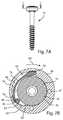
- FIG. 1Aillustrates a top perspective view of a system including a screw and a washer assembly
- FIG. 1Bis a bottom perspective view of the system of FIG. 1A ;
- FIG. 2Aillustrates a top perspective view of a washer of the washer assembly of FIG. 1A
- FIG. 2Billustrates a bottom perspective view of the washer of FIG. 2A
- FIG. 2Cillustrates a top view of the washer of FIG. 2A
- FIG. 2Dillustrates a side cross-sectional view of the washer of FIG. 2A ;
- FIG. 3Aillustrates a top perspective view of a cap of the washer assembly of FIG. 1A
- FIG. 3Billustrates a bottom perspective view of the cap of FIG. 3A
- FIG. 3Cillustrates a side view of the cap of FIG. 3A
- FIG. 3Dillustrates a bottom view of the cap of FIG. 3A
- FIG. 3Eillustrates a side cross-sectional view of the cap of FIG. 3A ;
- FIG. 4Aillustrates a top perspective exploded view of the system of FIG. 1A
- FIG. 4Billustrates a bottom perspective exploded view of the system of FIG. 1A ;
- FIG. 5Aillustrates a top view of the system of FIG. 1A
- FIG. 5Billustrates a longitudinal cross-sectional view of the system of FIG. 5A ;
- FIG. 6illustrates a top perspective view of the system of FIG. 1A , showing the washer assembly polyaxially pivoted relative to the screw;
- FIG. 7Aillustrates a side view of the system of FIG. 1A
- FIG. 7Billustrates a top cross-sectional view of the system of FIG. 7A with the system in an unlocked configuration in which the screw can rotate freely in a first direction relative to the washer assembly;
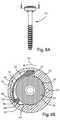
- FIG. 8Aillustrates a side view of the system of FIG. 1A
- FIG. 8Billustrates a top cross-sectional view of the system of FIG. 8A with the system in a locked configuration in which the screw and washer assembly are frictionally locked together so that the screw is unable to rotate freely in a second direction relative to the washer assembly;
- FIG. 9is a lateral view illustrating a surgical step in which a tip of a guide wire has been inserted across a facet joint of a lumbar portion of a spine, and a cannula inserter, with attached cannula, has been passed over the guide wire;
- FIG. 10is a lateral view of the lumbar spine, guide wire, cannula inserter, and cannula of FIG. 9 , illustrating a surgical step in which the cannula inserter, with attached cannula, has been advanced to a target location;
- FIG. 11is an enlarged detail view of a portion of the cannula inserter and cannula of FIG. 9 in a locked configuration
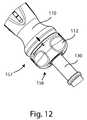
- FIG. 12is an enlarged detail view of a portion of the cannula inserter and cannula of FIG. 9 in an unlocked configuration
- FIG. 13is a lateral view of the lumbar spine, guide wire, and cannula inserter of FIG. 9 , illustrating a surgical step in which the cannula has been advanced to the target location over the dilator;
- FIG. 14is a lateral view of the lumbar spine, guide wire, and cannula inserter of FIG. 9 , illustrating a surgical step in which the cannula inserter has been withdrawn from the cannula, which remains at the target location;
- FIG. 15is an end view of the cannula inserter and cannula of FIG. 9 in the locked configuration
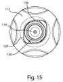
- FIG. 16is an end view of the cannula inserter and cannula of FIG. 9 in the unlocked configuration
- FIG. 17is a side perspective view of the cannula inserter and cannula of FIG. 9 in the locked configuration
- FIG. 18is a side perspective view of the cannula inserter and cannula of FIG. 9 in the locked configuration, with a knob of the cannula inserter hidden;
- FIG. 19is a side perspective view of the cannula inserter and cannula of FIG. 9 in the locked configuration, with the knob and a handle of the cannula inserter hidden;
- FIG. 20is a side perspective view of the cannula inserter and cannula of FIG. 9 in the unlocked configuration
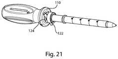
- FIG. 21is a side perspective view of the cannula inserter and cannula of FIG. 9 in the unlocked configuration, with the knob of the cannula inserter hidden;
- FIG. 22is a side perspective view of the cannula inserter and cannula of FIG. 9 in the unlocked configuration, with the knob and handle of the cannula inserter hidden;
- FIG. 23is a side perspective view of the cannula inserter and cannula of FIG. 9 in the unlocked configuration with a dilator portion of the cannula inserter in a retracted position;
- FIG. 24is a side perspective view of the cannula inserter and cannula of FIG. 9 in the unlocked configuration with the dilator retracted, with the knob of the cannula inserter hidden;
- FIG. 25is a side perspective view of the cannula inserter and cannula of FIG. 9 in the unlocked configuration with the dilator retracted, with the knob and handle of the cannula inserter hidden;
- FIG. 26is a side view of the cannula inserter and cannula of FIG. 21 in the unlocked configuration, with the knob hidden and the cannula alongside the cannula inserter.
- the present disclosurerelates to systems and methods used in orthopedic surgery, and in particular, to facet joint fixation.
- Those of skill in the artwill recognize that the systems and methods described herein may be readily adapted for other bone or joint fixation procedures.
- Those of skill in the artwill also recognize that the following description is merely illustrative of the principles of the technology, which may be applied in various ways to provide many different alternative embodiments. This description is made for the purpose of illustrating the general principles of this technology and is not meant to limit the inventive concepts in the appended claims.
- top and bottom perspective viewsillustrate a facet fixation screw system 10 , comprising a screw 20 and a washer assembly 40 .
- the washer assemblyis captive to the head of the screw.
- the washer assemblyincludes an anti-backout mechanism which allows the screw to be freely rotated in one direction relative to the washer assembly, but binds the screw to the washer assembly when the screw is rotated in the opposite direction.
- Screw 20includes a spherical head 22 and a shaft 24 .
- the shaft 24includes a threaded portion 26 extending along a portion of the shaft. The entire length of the shaft may be threaded, or some portion or portions thereof. The thread pitch may be constant along the threaded portion, or may vary.
- the shaft 24includes a cannulation 25 to allow placement of the screw over a guide wire, but non-cannulated embodiments may also be provided.
- a drive feature 28 on the head 22is shaped to cooperate with a driver instrument to facilitate placement, polyaxial adjustment and/or rotational driving of the screw.
- the drive featurehas a dogbone or bowtie shape; however other drive feature shapes are possible, including but not limited to: hexagon, pentagon, square, triangular, rectangular, cross, star, or other driver shapes known in the art.
- the drive feature 28may be a recess as shown; in other embodiments the drive feature 28 may protrude to cooperate with a driver instrument having a complementary recessed driving feature.
- the head 22further includes a spherical bearing surface 30 .
- the screw 20further includes a first end 32 which may be a proximal end, and at which the head 22 is located; and a second end 34 which may be a distal end, and at which a tip 36 of the shaft 24 is located.
- Washer assembly 40includes a washer 42 and cap 44 .
- the washer assemblymay further include a ball 46 (as best seen in FIGS. 4A and 4B ) which is captured between the washer 42 , the cap 44 , and the head 22 when the washer assembly is operatively assembled with the screw 20 as in FIGS. 1A and 1B .
- the system 10may be operatively assembled during manufacture and provided to the end users in the operatively assembled form, in sterile packaging.
- FIGS. 2A-2Dshow washer 42 in more detail.
- Washer 42is annular, and has a first end 48 and a second end 50 .
- First end 48terminates with a relatively thin annular lip 49 which may project slightly toward the center of the washer 42 .
- An outer peripheral wall 52extends exteriorly between the first end 48 and the second end 50 .
- An inner surface 54extends interiorly between the first end 48 and the second end 50 , forming a boundary to an aperture 55 .
- An annular spherical recess 56occupies a portion of the inner surface 54 , and may form a socket to receive screw head 22 .
- a portion of the annular spherical recess 56is bounded toward the first end 48 by a first shelf 60 , and the remainder is bounded toward the first end by a second shelf 62 , which is recessed from, and may be described as lower than, the first shelf 60 .
- a portion of the inner surface 54forms a ramp 63 .
- the ramp 63extends partially around the socket, or spherical recess 56 , between a first end 57 which is outwardly displaced from the socket and a second end 58 which is tangential to the socket.
- Alcove 64 having a partial circular cross sectionis recessed into the inner surface 54 ; at least a portion of the alcove 64 overlaps the ramp 63 , as seen in FIGS. 2A and 2D .
- Alcove 64includes a first shallow portion 65 and a second deep portion 66 , the depth of the alcove and the distance of the alcove from the spherical recess 56 increasing between the first and second portions.
- alcove 64has a cross section comprising an arc of a circle with a diameter which is complementary to the outer diameter of ball 46 . The diameter of the circle may be slightly less than the outer diameter of ball 46 , so that ball 46 is supported on the edges of alcove 64 .
- Alcove 64may be further described as a semicircular dished face, or a groove.
- At least one bore 67may extend longitudinally through the washer between the first end 48 and the second end 50 , and may, for example, provide access for cleaning during or after manufacturing.
- the second end 50 of the washer 42includes a bone engagement surface 68 , at least a portion of which may be compressed against bone material when the screw system is implanted.
- At least one spike 69protrudes from the second end 50 .
- the spikes 69may penetrate bone to provide additional fixation and/or rotation prevention.
- pegs, nails, pins, keels or other bone-penetrating featuresmay be included in place of or in addition to spikes 69 , or no bone-penetrating features may be included.
- the bone engagement surface 68may be roughened or porous to promote bone ongrowth or ingrowth; bone growth or other therapeutic agents may also be provided on the bone engagement surface 68 .
- the cap 44includes a ring 70 , the ring having a first side 72 and a second side 74 with an aperture 75 extending through the ring between the first and second sides 72 , 74 .
- a beam 76which may be a cantilever beam, projects from the second side 74 .
- a fixed end 78 of the beamis fixed to the ring, and a free end 80 is adjacent, but unconnected to, the ring 70 .
- a beam body 82extends between the fixed end 78 and the free end 80 , is curved to follow the curvature of the ring 70 , and may be parallel to the ring 70 .
- the beam 76may have the same radius of curvature as the ring 70 , so that it extends along and overlaps a portion of the ring 70 .
- the aperture 75may include a lip 77 which has a diameter smaller than the equatorial diameter of the screw head 22 .
- FIGS. 4A-4Bdepict screw system 10 in exploded views
- FIG. 5Bis a cross-sectional view of the system in an operatively assembled configuration.
- screw 20is received through washer 42 , with tip 36 oriented in the same general direction as second end 50 , and head 22 toward first end 48 .
- Screw head 22is retained by washer 42 , with spherical bearing surface 30 bearing against annular spherical recess 56 .
- Head 22 and washer 42may thus form a ball and socket joint, with head 22 polyaxially pivotable relative to washer 42 , as seen best in FIG. 6 .
- Ball 46is positioned inside washer 42 on second shelf 62 , between head 22 and alcove 46 .
- Cap 44is positioned on washer 42 , with a portion of ring 70 resting on first shelf 60 .
- beam 76extends from the second side 74 of the cap and is received in a gap 86 formed between head 22 , second shelf 42 , and inner surface 54 of washer 42 .
- Free end 80 of beam 76is adjacent alcove 64 of the washer, and ball 46 is between free end 80 and head 22 .
- the free end 80continuously spring biases the ball 46 toward the second end of the ramp 63 .
- ball 46may be biased toward the second end of the ramp 63 by another kind of known spring, such as a spring clip, retaining ring, compression spring, extension spring, leaf spring, or torsion spring.
- ball 46may be biased toward the second end of the ramp 63 by other known biasing means, such as magnetic bias, gravitational bias, or shape memory bias.
- Cap 44is secured to washer 42 through a press-fit connection; as cap is pressed onto washer 42 in the described position, lip 49 of the washer may be deformed.
- cap 44may be secured to washer 42 by laser welding, a snap fit, a taper fit, a friction fit, threads, or any other known suitable connection means. It is appreciated that head 22 is polyaxially pivotable relative to washer 42 both before and after cap 44 is attached to washer 42 .
- screw 20when screw system 10 is operatively assembled, screw 20 can rotate freely relative to washer assembly 40 in a first direction, but becomes rigidly locked to washer assembly 40 when rotated in a second direction.
- head 22may be freely rotated in a first direction 90 , which may be clockwise.
- ball 46is urged along alcove 64 in ramp 63 , from shallow portion 65 toward deep portion 66 .
- the beamis deflected toward deep portion 66 , and the spring bias of the beam is temporarily overcome, allowing free rotation of the head 22 .
- a small gapis shown between ball 46 and head 22 , it is appreciated that ball 46 and head 22 may be in slight contact, yet head 22 is still able to freely rotate relative to washer 42 .
- rotation of head 22 in a second direction 92causes a frictional lock to form between head 22 and washer assembly 40 .
- ball 46is urged along alcove 64 in ramp 63 toward shallow end 65 .
- Ball 46is further urged toward shallow end 65 by the spring bias of beam 76 .
- Ball 46becomes jammed or wedged between alcove 64 and head 22 , and may be deformed against head 22 as a result of the wedging action.
- ball 46becomes wedged between two points of contact along the edges of alcove 64 and a single point of contact with head 22 ; the single point of contact may transform into a contact patch or area due to deformation of the ball 46 against the head 22 . Further rotation of head 22 in the second direction is prevented; however washer 42 may still be polyaxially pivotable relative to head 22 .
- FIGS. 9-26illustrate a cannula insertion instrument 100 and cannula 130 , which may be components of a cannula insertion system.
- the cannula insertion instrumentmay also be referred to as a cannula inserter 100 .
- the cannula insertermay releasably couple to the cannula, dilate a path through soft tissue, insert the cannula into or through the tissue, and uncouple from the cannula to leave the cannula in place in the tissue.
- the cannula insertion systemmay include a locked configuration and an unlocked configuration. In the locked configuration, the cannula may be locked to the cannula inserter so that there is minimal motion between components.
- the cannulaIn the unlocked configuration, the cannula may be allowed to disengage from the cannula inserter. In the unlocked configuration, a dilator component 114 of the cannula inserter may be allowed to slide relative to remaining components of the cannula inserter along a central axis of the cannula inserter.
- the cannula inserter 100may include a handle 110 , a knob 112 , a dilator 114 , a first pin 122 , a second pin 126 , and a spring 140 .
- the handle 110may be an elongated part extending between a distal portion 152 and a proximal portion 154 .
- the handlemay include a capture feature 124 ( FIG. 18 ).
- the capture featuremay be a slot which receives the first pin 122 .
- the slotmay be shaped or sized so there is interference on the first pin 122 when the first pin is between the locked and unlocked configurations.
- the majority of the capture featuremay be equal to or narrower than the outer diameter of the first pin.
- the capture featuremay include one or more enlarged portions which are equal to or wider than the outer diameter of the first pin. The enlarged portions may coincide with functional positions of the first pin in the capture feature.
- the handlemay also include a keyway 129 , which may be located in the distal portion. The handle may be cannulated along its length.
- the knob 112may be a generally cylindrical part extending between a distal portion 156 and a proximal portion 157 .
- the knobmay include a central aperture 120 .
- the aperturemay be circular or non-circular, and may extend through the entire knob.
- the illustrated aperture 120is generally circular and is enlarged in one direction by opposing alcoves or keyways.
- the knob or the aperturemay include additional engagement features characteristic of a quick connect, quarter turn connection, tongue and groove connection, or bayonet connection.
- the aperturemay be threaded or tapered.
- the aperturemay include a releasable snap connection or collet.
- the knobmay be cannulated along its length.
- the dilator 114may be an elongated part extending between a proximal portion 142 and a distal portion 118 ( FIG. 25 ).
- the distal portionmay be described as a tip 118 .
- the dilatormay include a shaft 116 extending between the proximal and distal portions.
- the shaftmay be smaller in diameter than the proximal or distal portions.
- the dilatormay also include a groove 128 which receives the first pin 122 .
- the groovemay be adjacent to a flat 158 .
- the groove and the flatmay form an angle, which may be obtuse, right, or acute.
- the dilatormay include another flat 160 which may be proximal to the flat 158 .
- the dilatormay be cannulated along its length.
- the cannula 130may be an elongated tubular part extending between a distal portion 134 and a proximal portion 162 .
- the cannulamay include a central bore 132 along its length.
- An engagement feature 136may be present on the proximal portion.
- the engagement featuremay include at least one protrusion. In the illustrated example, the engagement feature includes two opposing protrusions, or tabs.
- the engagement featuremay be complementary to the knob aperture 120 , any additional engagement features of the knob that may be present, and/or the handle keyway 129 .
- the cannulamay include depth marks or other indicia or markings.
- the cannula inserter 100may be assembled by sliding the knob proximal portion 157 onto the handle distal portion 152 and sliding the spring 140 and the dilator proximal portion 142 into the handle distal portion.
- the dilatormay be coupled to the handle by the second pin 126 so that the dilator is rotationally fixed relative to the handle and axially slidable relative to the handle, at least within a limited range of axial motion.
- the second pinis shown adjacent to the flat 160 , an arrangement that may provide the rotational and axial constraints between the dilator and handle.
- the springmay bias the dilator to one end of the range of axial motion.
- the springmay be compressed between the handle and the dilator so that the spring urges the dilator to protrude distally from the handle.
- the knobmay be coupled to the handle by the first pin 122 so that the knob is axially fixed relative to the handle and rotatable relative to the handle, at least within a limited range of rotational motion.
- the first pinis shown inserted through the knob so that the first pin is received in the handle capture feature 124 , an arrangement that may provide the rotational and axial constraints between the knob and the handle.
- the first pinmay also engage the dilator groove 128 so that rotation of the knob selectively prevents or allows the dilator to slide axially relative to the handle.
- the first pinis shown in dilator groove 128 when the knob is rotated to a first position, which may be a locked position.
- the first pinis shown adjacent to the flat 158 when the knob is rotated to a second position, which may be an unlocked position.
- the handle and/or knobmay include markings or other indicia to show when the knob is in the locked position or the unlocked position.
- the cannula inserter 100 and cannula 130may be assembled by rotating the knob 112 to the unlocked position, sliding the dilator tip 118 into the proximal portion 162 of the cannula bore 132 , aligning the cannula engagement feature 136 with the knob aperture 120 , sliding the cannula engagement feature into the knob aperture, and rotating the knob to the locked position.
- FIG. 10illustrates that the cannula engagement feature may also fit into the handle keyway 129 .
- the cannulais rotationally fixed to the handle by the complementary noncircular shapes of the cannula engagement feature and the handle keyway, while the cannula is axially a fixed to the cannula inserter by the misalignment of the knob aperture and the cannula engagement feature when the knob is in the locked position.
- knob 112is shown in the first or locked position, in which the instrument is in the locked configuration.
- the instrument handle 110 and knob 112are in a fixed position relative to the shaft 116 and dilator 114 , and the cannula 130 is also in a fixed position relative to the cannula inserter 100 .
- knob 112is shown rotated to the second or unlocked position, which changes the instrument from the locked configuration to the unlocked configuration.
- FIGS. 15 and 16are distal end views of cannula inserter 100 , showing the concentric arrangement of the knob 112 , cannula 130 , and dilator 114 .
- knob 112is in the first, or locked position. In this position, the knob aperture 120 is positioned relative to the cannula engagement feature 136 such that the cannula engagement feature 136 is prevented from moving through the aperture 120 . In this configuration, the cannula 130 is locked into engagement with the cannula inserter 100 .
- knob 112is in the second, or unlocked position.
- the cannula engagement feature 136which in this embodiment comprises at least one protrusion, is aligned with the knob aperture, and the cannula may be disengaged from the instrument.
- FIGS. 17 , 18 , and 19show various views of the cannula inserter 100 in the locked configuration.
- FIG. 18has the knob 112 removed to show how the first pin 122 rests in the capture feature 124 of the handle; in this embodiment the capture feature is an undercut or a slot. It also shows how the cannula 130 is keyed to the end of the handle 110 , as engagement feature 136 is captive in the keyway 129 .
- FIG. 19has the cannula and handle removed to show the first pin 122 and the second pin 126 .
- the first or distal pin 122rests in the groove 128 on the dilator 114 and prevents the dilator from sliding along the central axis relative to the rest of the instrument, while in the locked configuration.
- the second or proximal pin 126prevents rotation of the dilator 114 with respect to the handle 110 .
- FIGS. 20 , 21 , and 22show the same three views shown previously, only in the unlocked configuration.
- the first or distal pin 122moves in the capture feature 124 on the end of the handle 110 ( FIG. 21 ).
- This capture featuremay be a slot shaped so there is interference, or drag, on the pin 122 when the pin 122 is between configurations.
- the pin 122snaps into position when in either configuration.
- FIG. 22shows the first pin 122 rotated out of the groove 128 on the dilator 114 allowing the dilator to slide along the central axis relative to the rest of the instrument.
- FIGS. 23 , 24 and 25show the same three views shown previously, only in an unlocked configuration with the dilator slid proximally so that a portion is retracted into the rest of the instrument.
- FIG. 25shows that the spring 140 is compressed as the dilator 114 slides in, or proximally.
- the spring 140presses between the handle 110 and the dilator 114 and keeps the dilator slid out, or distally, when no outside forces are acting on the instrument ( FIG. 22 ).
- the proximal end 142 of the dilator 114may exit the handle 110 when the dilator is retracted and thus may act as an indicator that the dilator has slid in.
- FIG. 26displays cannula inserter 100 minus knob 112 , in the unlocked configuration. Cannula 130 is shown alongside the cannula inserter.
- the cannula inserter 100 and/or cannula 130may be formed of molded parts, and may be suitable for single use.
- the cannula inserter, or selected components thereof, or the cannulamay be formed of metal, glass, polymer, ceramic, wood, composite materials, or other materials. Any component may be formed of a combination of materials, the material in each portion selected according to the function and working load of the portion.
- screw system 10may be implanted across a facet joint to provide joint fixation, preventing articulation of the joint.
- a guide wiremay be inserted across the joint, and a cannula inserted over the guide wire to the proximal facet.
- a cannula insertion system providing tissue dilation and cannula insertionsuch as that disclosed herein and in U.S. Provisional Patent Application No. 61/374862, incorporated by reference into this disclosure, may be used to insert the cannula.
- the cannulamay be temporarily docked to the proximal facet.
- a guide wire 150may be inserted across a facet joint to establish an insertion trajectory for screw system 10 .
- the illustrated trajectoryis generally postero-cephalad to antero-caudal.
- the guide wireis shown deeply inserted within an inferior pedicle associated with the facet joint.
- the cannula inserter 100 and cannula 130may be assembled and set to the locked configuration as described above.
- Cannula inserter 100 and cannula 130may be started over the guide wire 150 and moved through intervening soft tissue toward a target location while in the locked configuration.
- the target locationis a facet joint in a spine. More specifically, the illustrated target location is a location on an inferior articular process of the facet joint.
- Cannula 130is releasably locked to the cannula inserter 100 and extends longitudinally along the shaft 116 of the instrument, such that the bore 132 of the cannula 130 surrounds the shaft 116 and the dilator 114 protrudes from the cannula bore 132 .
- cannula inserter 100has been moved through the soft tissue and the distal tip 118 of dilator 114 is at the target location. However, the distal portion 134 of the cannula 130 remains at a distance from the target location.
- the cannula inserter 100has been set to the unlocked configuration.
- the handle 110 , knob 112 and cannula 130have moved toward the target location, translating along the dilator shaft 116 toward the tip 118 .
- dilator 114is received in the bore 132 of the cannula 130 .
- a distal end 134 of the cannulamay directly contact the target location, which may be a bone.
- the target locationis an inferior facet.
- the dilator tip 118may push against the target location as the cannula 130 , handle 110 and knob 112 translate relative to the shaft 116 .
- the unlocked cannula inserter 100has been withdrawn proximally along the guide wire 150 , leaving cannula 130 in situ at the target location.
- the operatively assembled screw system 10may be inserted through the cannula 130 to the facet joint, with the screw first end 34 leading.
- a driveris used to rotate screw 20 in the first direction 90 , driving screw 20 through the facets and across the joint.
- washer 42comes in contact with the proximal facet, with at least a portion of bone engagement surface 68 in contact with the bony material of the facet.
- the polyaxial adjustability of the washer assembly relative to the screwallows the washer to sit at an angled position relative to the screw, which may be dictated by the surface topography of the facet and/or the surrounding environment.
- spikes 69may penetrate the surface of the facet, providing enhanced fixation and anti-rotation.
- Screw system 10may be used in other applications in which two bone segments are fixed or compressed together to provide fixation or arthrodesis of a joint.
- the systemmay also be used in any orthopedic application in which anti-backout capabilities are desired, for example, to attach a prosthesis or implant to a bone.
- Non-limiting examplesinclude attachment of articulating facet joint prostheses to vertebrae, attachment of intervertebral disk replacement prostheses, attachment of spinal rods, attachment of bone plates, and attachment of other joint prostheses, including knee, hip, shoulder, wrist, and/or ankle prostheses.
- Screw system 10may also provide an anchor for anchoring of sutures, or natural or artificial tissues such as muscle, tendon, or ligament.
- washer assembly 40may be modified by replacing washer 42 with an alternate component, which may include some or all of the features described above for washer 42 .
- system 10are preferably formed of titanium or titanium alloy.
- system 10 or any of its component partsmay comprise cobalt-chrome and its alloys, stainless-steel, titanium and its alloys, titanium carbide, titanium nitride, ion-implantation of titanium, diffusion hardened metals, diamond like coatings, diamond-like carbon, zirconium nitride, niobium, oxinium or oxidized zirconium, ceramics such as alumina and zirconia, polymers, or other biocompatible materials. Any part may comprise a combination of any of the materials listed, and the system 10 may comprise parts made of differing materials.
- the cannula inserter 100may include a plurality of dilators 114 of varying or graduated diameters. This plurality of intermediate dilators may be positioned between an initial or smallest dilator and the final cannula 130 .
- the knob 112may include intermediate positions that selectively free up or unlock the intermediate dilators to slide into the handle.
- the spring 140may be omitted from the assembly.
- the cannula inserter 100may include a ratchet system to retract the dilator.
- the cannula inserter 100 and cannula 130may be used without a guide wire.
- Another examplemay include other locking connections between the cannula and the instrument, such as a releasable snap fit, a threaded connection, a tongue and groove connection, a tab or button and slot connection, among other locking connections.
- any of the components disclosed hereinmay include surface treatments or additives in one or more of the component materials to provide beneficial effects such as anti-microbial, analgesic or anti-inflammatory properties.
- Any of the components disclosed hereinmay include coatings or treatments to provide surface roughening, including but not limited to knurling or porous coating, among others. Such treatments may be directionally applied to promote movement between component parts in one direction, and/or increase friction between component parts in another direction.
Landscapes
- Health & Medical Sciences (AREA)
- Orthopedic Medicine & Surgery (AREA)
- Life Sciences & Earth Sciences (AREA)
- Surgery (AREA)
- Neurology (AREA)
- Molecular Biology (AREA)
- General Health & Medical Sciences (AREA)
- Biomedical Technology (AREA)
- Heart & Thoracic Surgery (AREA)
- Medical Informatics (AREA)
- Nuclear Medicine, Radiotherapy & Molecular Imaging (AREA)
- Animal Behavior & Ethology (AREA)
- Engineering & Computer Science (AREA)
- Public Health (AREA)
- Veterinary Medicine (AREA)
- Pathology (AREA)
- Physics & Mathematics (AREA)
- Biophysics (AREA)
- Optics & Photonics (AREA)
- Radiology & Medical Imaging (AREA)
- Surgical Instruments (AREA)
Abstract
Description
Claims (5)
Priority Applications (2)
| Application Number | Priority Date | Filing Date | Title |
|---|---|---|---|
| US13/211,807US9078707B2 (en) | 2009-12-01 | 2011-08-17 | Polyaxial facet fixation screw system with cannula inserter |
| PCT/US2011/048196WO2012024467A1 (en) | 2010-08-18 | 2011-08-18 | Polyaxial facet fixation screw system with cannula inserter |
Applications Claiming Priority (4)
| Application Number | Priority Date | Filing Date | Title |
|---|---|---|---|
| US26561409P | 2009-12-01 | 2009-12-01 | |
| US37486210P | 2010-08-18 | 2010-08-18 | |
| US12/957,056US8529609B2 (en) | 2009-12-01 | 2010-11-30 | Polyaxial facet fixation screw system |
| US13/211,807US9078707B2 (en) | 2009-12-01 | 2011-08-17 | Polyaxial facet fixation screw system with cannula inserter |
Related Parent Applications (1)
| Application Number | Title | Priority Date | Filing Date |
|---|---|---|---|
| US12/957,056Continuation-In-PartUS8529609B2 (en) | 2009-06-23 | 2010-11-30 | Polyaxial facet fixation screw system |
Publications (2)
| Publication Number | Publication Date |
|---|---|
| US20110319925A1 US20110319925A1 (en) | 2011-12-29 |
| US9078707B2true US9078707B2 (en) | 2015-07-14 |
Family
ID=44534697
Family Applications (1)
| Application Number | Title | Priority Date | Filing Date |
|---|---|---|---|
| US13/211,807Active2031-07-26US9078707B2 (en) | 2009-12-01 | 2011-08-17 | Polyaxial facet fixation screw system with cannula inserter |
Country Status (2)
| Country | Link |
|---|---|
| US (1) | US9078707B2 (en) |
| WO (1) | WO2012024467A1 (en) |
Cited By (4)
| Publication number | Priority date | Publication date | Assignee | Title |
|---|---|---|---|---|
| US20200268423A1 (en)* | 2019-02-27 | 2020-08-27 | Warsaw Orthopedic, Inc. | Anatomy buttressing adaptor |
| US11219531B2 (en) | 2019-04-10 | 2022-01-11 | Wenzel Spine, Inc. | Rotatable intervertebral spacing implant |
| US12102348B2 (en) | 2016-09-07 | 2024-10-01 | Vertos Medical, Inc. | Percutaneous lateral recess resection methods and instruments |
| US12324572B2 (en) | 2022-06-16 | 2025-06-10 | Vertos Medical, Inc. | Integrated instrument assembly |
Families Citing this family (8)
| Publication number | Priority date | Publication date | Assignee | Title |
|---|---|---|---|---|
| US20140222088A1 (en)* | 2011-05-08 | 2014-08-07 | Spinal Ventures, Llc | Implant and Fastener Fixation Devices and Delivery Instrumentation |
| US20140088647A1 (en)* | 2012-09-21 | 2014-03-27 | Atlas Spine, Inc. | Minimally invasive spine surgery instruments: spinal rod with flange |
| US20140180428A1 (en)* | 2012-12-21 | 2014-06-26 | Wright Medical Technology, Inc. | Percutaneous expanding hammertoe implant |
| US9730737B2 (en)* | 2013-03-14 | 2017-08-15 | Atlas Spine, Inc. | Facet fixation with anchor wire |
| FR3040285B1 (en)* | 2015-08-31 | 2017-09-15 | Bpath | VERTEBRAL IMPLANT, METHOD FOR SETTING SUCH IMPLANT AND TOOL FOR IMPLANT PLACEMENT |
| US11045305B2 (en) | 2016-08-26 | 2021-06-29 | Paragon 28, Inc. | Soft tissue retention devices, instrumentation and related methods |
| CA3099263C (en)* | 2018-05-04 | 2022-05-10 | Paragon 28, Inc. | Soft tissue retention device, instrumentation and related methods |
| US20240148510A1 (en)* | 2022-10-10 | 2024-05-09 | Astura Medical Inc. | Anti-rotation mechanism for a sacroiliac screw |
Citations (75)
| Publication number | Priority date | Publication date | Assignee | Title |
|---|---|---|---|---|
| US324768A (en) | 1885-08-18 | Tubular screw | ||
| US958127A (en) | 1909-11-04 | 1910-05-17 | Knut T Hovrud | Pole-anchor. |
| US1155844A (en) | 1914-12-12 | 1915-10-05 | Albert E Smith | Nut-lock. |
| US1391186A (en) | 1921-01-22 | 1921-09-20 | Raymond T Hill | Nut-lock |
| US1428111A (en) | 1920-09-16 | 1922-09-05 | Molesworth Frank | Nail for packing cases and the like |
| US1609645A (en) | 1923-02-21 | 1926-12-07 | Miller & Pardee Inc | Bolt |
| US1627404A (en) | 1925-04-04 | 1927-05-03 | Kiblok Sa Des Ets | Nut lock |
| US1792381A (en) | 1927-07-13 | 1931-02-10 | Paul Adnet | Locking nut |
| US2583896A (en) | 1949-09-06 | 1952-01-29 | Siebrandt Inc | Bone clamp |
| US2769441A (en)* | 1954-10-22 | 1956-11-06 | Abramson Daniel Jerome | Speculum |
| US3181584A (en) | 1959-08-21 | 1965-05-04 | George K Garrett Company | Screw-and-washer pre-assembly |
| US3865307A (en) | 1973-10-12 | 1975-02-11 | Luke J Schiro | Locking railroad spike |
| US4290328A (en) | 1980-02-15 | 1981-09-22 | Vermont American Corp. | Ratchet handle |
| US5125489A (en) | 1990-10-09 | 1992-06-30 | Cha Pyong I | High-torque dual-purpose hub assembly for the rear wheel of a multispeed bicycle |
| US5261909A (en) | 1992-02-18 | 1993-11-16 | Danek Medical, Inc. | Variable angle screw for spinal implant system |
| US5478342A (en) | 1994-06-30 | 1995-12-26 | Spinetech, Inc. | Reversible bone screw lock |
| US5527312A (en) | 1994-08-19 | 1996-06-18 | Salut, Ltd. | Facet screw anchor |
| US5556411A (en)* | 1993-07-09 | 1996-09-17 | Nissho Corporation | Trocar assembly having a cannula retaining member |
| US5611800A (en) | 1994-02-15 | 1997-03-18 | Alphatec Manufacturing, Inc. | Spinal fixation system |
| US5893889A (en) | 1997-06-20 | 1999-04-13 | Harrington; Michael | Artificial disc |
| US5908431A (en)* | 1995-12-15 | 1999-06-01 | Battenfield; Harold L. | Carpal tunnel surgery instruments |
| US6148696A (en) | 1999-06-01 | 2000-11-21 | Chiang; Shu Chi | Ratchet screw driver |
| US6227782B1 (en) | 1999-05-28 | 2001-05-08 | Stephen Bowling | Self-locking threaded fastener assembly |
| US6248108B1 (en) | 1998-09-30 | 2001-06-19 | Bionx Implants Oy | Bioabsorbable surgical screw and washer system |
| US6443987B1 (en) | 2000-09-15 | 2002-09-03 | Donald W. Bryan | Spinal vertebral implant |
| US6485518B1 (en) | 1999-12-10 | 2002-11-26 | Nuvasive | Facet screw and bone allograft intervertebral support and fusion system |
| US6502679B1 (en) | 2001-07-23 | 2003-01-07 | Ming Cheng Wang | Low-noise low-friction resistance, one-way drive car wheel assembly |
| US20030032960A1 (en) | 2000-10-27 | 2003-02-13 | Michael Dudasik | Facet fixation devices |
| US6565573B1 (en) | 2001-04-16 | 2003-05-20 | Smith & Nephew, Inc. | Orthopedic screw and method of use |
| EP0932367B1 (en) | 1995-06-07 | 2003-11-19 | SDGI Holdings, Inc. | Anterior spinal instrumentation |
| WO2004019757A2 (en) | 2002-08-29 | 2004-03-11 | Loubert Suddaby | Spinal facet fixation device |
| US20050077688A1 (en)* | 2003-09-30 | 2005-04-14 | Voegele Aaron C. | Multi-angled duckbill seal assembly |
| US20050228386A1 (en) | 2004-04-08 | 2005-10-13 | Tara Ziolo | Bone fixation device |
| WO2006017507A2 (en) | 2004-08-03 | 2006-02-16 | Triage Medical | Telescopic percutaneous tissue dilation systems and related methods |
| US20060074425A1 (en) | 2002-09-11 | 2006-04-06 | Chester Sutterlin | Systems and methods for removing body tissue |
| US20060111779A1 (en) | 2004-11-22 | 2006-05-25 | Orthopedic Development Corporation, A Florida Corporation | Minimally invasive facet joint fusion |
| US7060068B2 (en) | 2000-10-24 | 2006-06-13 | Sdgi Holdings, Inc. | Vertebrae fastener placement guide |
| US20060217713A1 (en) | 2005-03-24 | 2006-09-28 | Serhan Hassan A | Low profile spinal tethering devices |
| US20060235391A1 (en) | 2005-03-08 | 2006-10-19 | Sutterlin Chester Iii | Facet joint stabilization |
| US20060287583A1 (en)* | 2005-06-17 | 2006-12-21 | Pool Cover Corporation | Surgical access instruments for use with delicate tissues |
| WO2007070819A2 (en) | 2005-12-14 | 2007-06-21 | Spinefrontier Lls | Spinous process fixation implant |
| WO2007084900A2 (en) | 2006-01-17 | 2007-07-26 | Spinefrontier Lls | Apparatus and method for spine fixation |
| US7261506B2 (en) | 2000-03-09 | 2007-08-28 | Hanna Maria Smolarek | Washer and threaded fastener assembly incorporating same |
| WO2007109402A2 (en) | 2006-03-21 | 2007-09-27 | Spinefrontier Lls | Spinous process fixation device |
| WO2007120903A2 (en) | 2006-04-14 | 2007-10-25 | Blackstone Medical, Inc. | Percutaneous facet fusion system and method |
| WO2007127687A2 (en) | 2006-04-24 | 2007-11-08 | Spinefrontier Lls | Improved spine fixation method and apparatus |
| WO2007127610A1 (en) | 2006-04-25 | 2007-11-08 | Warsaw Orthopedic, Inc. | Facet fusion implants and methods of use |
| US7294128B2 (en) | 2002-04-09 | 2007-11-13 | Nas Medical Technologies, Inc. | Bone fixation apparatus |
| WO2007143709A2 (en) | 2006-06-07 | 2007-12-13 | Spinefrontier Lls | Methods and devices for static or dynamic spine stabilization |
| US20080021480A1 (en) | 2006-07-21 | 2008-01-24 | Spinefrontier Lls | System and method for spine fixation |
| US20080147079A1 (en) | 2006-12-15 | 2008-06-19 | Spinefrontier Lls | Guidance system,tools and devices for spinal fixation |
| US7396360B2 (en) | 2004-09-29 | 2008-07-08 | The Cleveland Clinic Foundation | Minimally invasive method and apparatus for fusing adjacent vertebrae |
| WO2008086533A2 (en) | 2007-01-11 | 2008-07-17 | Lanx, Inc. | Spinal implants and methods |
| WO2008106240A2 (en) | 2007-02-26 | 2008-09-04 | Depuy Spine, Inc. | Intra- facet fixation device and method of use |
| US20080255622A1 (en) | 2007-04-13 | 2008-10-16 | Depuy Spine, Inc. | Facet fixation and fusion screw and washer assembly and method of use |
| WO2008127415A1 (en) | 2007-04-13 | 2008-10-23 | Horton Kenneth L | Allograft spinal facet fusion system |
| WO2008153732A1 (en) | 2007-05-22 | 2008-12-18 | Vg Innovations, Llc | Method and apparatus for spinal facet fusion |
| WO2009006622A2 (en) | 2007-07-03 | 2009-01-08 | Innovative Spinal Technologies, Inc. | Facet fusion implant |
| US20090054903A1 (en) | 2002-10-10 | 2009-02-26 | Mark Falahee | Bone fixation implant system and method |
| US20090076551A1 (en) | 2004-11-22 | 2009-03-19 | Petersen David A | Methods and surgical kits for minimally-invasive facet joint fusion |
| US20090099602A1 (en) | 2007-09-11 | 2009-04-16 | Kamran Aflatoon | Method of lateral facet approach, decompression and fusion using screws and staples as well as arthroplasty |
| US7522953B2 (en) | 2001-09-25 | 2009-04-21 | Nuvasive, Inc. | System and methods for performing surgical procedures and assessments |
| WO2009067486A2 (en) | 2007-11-19 | 2009-05-28 | David Lee | Method and apparatus for spinal facet joint fusion using irregularly shaped cortical bone implants |
| US7563275B2 (en) | 2002-10-10 | 2009-07-21 | U.S. Spinal Technologies, Llc | Bone fixation implant system and method |
| US20090192551A1 (en) | 2008-01-24 | 2009-07-30 | Jason Cianfrani | Facet Fixation Prosthesis |
| US7575343B2 (en) | 2007-05-17 | 2009-08-18 | Osram Sylvania Inc. | Faceted par lamp |
| US20090234397A1 (en) | 2004-11-22 | 2009-09-17 | Petersen David A | Methods and Surgical Kits for Minimally-Invasive Facet Joint Fusion |
| WO2009134888A2 (en) | 2008-04-30 | 2009-11-05 | Kyphon Sarl | Apparatus and methods for inserting facet screws |
| US20090312798A1 (en) | 2008-06-16 | 2009-12-17 | Armando Varela | Transfacet fixation assembly and related surgical methods |
| US20090312800A1 (en) | 2007-07-18 | 2009-12-17 | Spinefrontier Inc | System and method for facet fixation |
| US20100174324A1 (en) | 2007-04-17 | 2010-07-08 | Newclip Technics SAS | Implantable orthopaedic device composed of a support structure having at least one orifice associated with a nut, for the passage of a locking screw |
| US7824429B2 (en) | 2002-07-19 | 2010-11-02 | Interventional Spine, Inc. | Method and apparatus for spinal fixation |
| US20110087169A1 (en)* | 2009-10-08 | 2011-04-14 | Parihar Shailendra K | Trocar Assembly |
| US8128666B2 (en) | 2003-03-24 | 2012-03-06 | Medical Designs, Llc | Low profile screw anchor with variable axis/angle fixation |
| US8162942B2 (en) | 2004-03-31 | 2012-04-24 | Orthofix S.R.L. | Intramedullary nail comprising elements of shape-memory material |
Family Cites Families (4)
| Publication number | Priority date | Publication date | Assignee | Title |
|---|---|---|---|---|
| US20060004398A1 (en)* | 2004-07-02 | 2006-01-05 | Binder Lawrence J Jr | Sequential dilator system |
| US20060030872A1 (en)* | 2004-08-03 | 2006-02-09 | Brad Culbert | Dilation introducer for orthopedic surgery |
| US8870890B2 (en)* | 2005-08-05 | 2014-10-28 | DePuy Synthes Products, LLC | Pronged holder for treating spinal stenosis |
| EP2120746A2 (en)* | 2007-01-05 | 2009-11-25 | TRANS1, Inc. | Percutaneous delivery of facet screws using depth control indicator |
- 2011
- 2011-08-17USUS13/211,807patent/US9078707B2/enactiveActive
- 2011-08-18WOPCT/US2011/048196patent/WO2012024467A1/enactiveApplication Filing
Patent Citations (82)
| Publication number | Priority date | Publication date | Assignee | Title |
|---|---|---|---|---|
| US324768A (en) | 1885-08-18 | Tubular screw | ||
| US958127A (en) | 1909-11-04 | 1910-05-17 | Knut T Hovrud | Pole-anchor. |
| US1155844A (en) | 1914-12-12 | 1915-10-05 | Albert E Smith | Nut-lock. |
| US1428111A (en) | 1920-09-16 | 1922-09-05 | Molesworth Frank | Nail for packing cases and the like |
| US1391186A (en) | 1921-01-22 | 1921-09-20 | Raymond T Hill | Nut-lock |
| US1609645A (en) | 1923-02-21 | 1926-12-07 | Miller & Pardee Inc | Bolt |
| US1627404A (en) | 1925-04-04 | 1927-05-03 | Kiblok Sa Des Ets | Nut lock |
| US1792381A (en) | 1927-07-13 | 1931-02-10 | Paul Adnet | Locking nut |
| US2583896A (en) | 1949-09-06 | 1952-01-29 | Siebrandt Inc | Bone clamp |
| US2769441A (en)* | 1954-10-22 | 1956-11-06 | Abramson Daniel Jerome | Speculum |
| US3181584A (en) | 1959-08-21 | 1965-05-04 | George K Garrett Company | Screw-and-washer pre-assembly |
| US3865307A (en) | 1973-10-12 | 1975-02-11 | Luke J Schiro | Locking railroad spike |
| US4290328A (en) | 1980-02-15 | 1981-09-22 | Vermont American Corp. | Ratchet handle |
| US5125489A (en) | 1990-10-09 | 1992-06-30 | Cha Pyong I | High-torque dual-purpose hub assembly for the rear wheel of a multispeed bicycle |
| US5261909A (en) | 1992-02-18 | 1993-11-16 | Danek Medical, Inc. | Variable angle screw for spinal implant system |
| US5556411A (en)* | 1993-07-09 | 1996-09-17 | Nissho Corporation | Trocar assembly having a cannula retaining member |
| US5611800A (en) | 1994-02-15 | 1997-03-18 | Alphatec Manufacturing, Inc. | Spinal fixation system |
| US5478342A (en) | 1994-06-30 | 1995-12-26 | Spinetech, Inc. | Reversible bone screw lock |
| US5527312A (en) | 1994-08-19 | 1996-06-18 | Salut, Ltd. | Facet screw anchor |
| EP0932367B1 (en) | 1995-06-07 | 2003-11-19 | SDGI Holdings, Inc. | Anterior spinal instrumentation |
| US5908431A (en)* | 1995-12-15 | 1999-06-01 | Battenfield; Harold L. | Carpal tunnel surgery instruments |
| US5893889A (en) | 1997-06-20 | 1999-04-13 | Harrington; Michael | Artificial disc |
| US6248108B1 (en) | 1998-09-30 | 2001-06-19 | Bionx Implants Oy | Bioabsorbable surgical screw and washer system |
| US6227782B1 (en) | 1999-05-28 | 2001-05-08 | Stephen Bowling | Self-locking threaded fastener assembly |
| US6148696A (en) | 1999-06-01 | 2000-11-21 | Chiang; Shu Chi | Ratchet screw driver |
| US6485518B1 (en) | 1999-12-10 | 2002-11-26 | Nuvasive | Facet screw and bone allograft intervertebral support and fusion system |
| US7261506B2 (en) | 2000-03-09 | 2007-08-28 | Hanna Maria Smolarek | Washer and threaded fastener assembly incorporating same |
| US6443987B1 (en) | 2000-09-15 | 2002-09-03 | Donald W. Bryan | Spinal vertebral implant |
| US7060068B2 (en) | 2000-10-24 | 2006-06-13 | Sdgi Holdings, Inc. | Vertebrae fastener placement guide |
| US20030032960A1 (en) | 2000-10-27 | 2003-02-13 | Michael Dudasik | Facet fixation devices |
| US6565573B1 (en) | 2001-04-16 | 2003-05-20 | Smith & Nephew, Inc. | Orthopedic screw and method of use |
| US6502679B1 (en) | 2001-07-23 | 2003-01-07 | Ming Cheng Wang | Low-noise low-friction resistance, one-way drive car wheel assembly |
| US7522953B2 (en) | 2001-09-25 | 2009-04-21 | Nuvasive, Inc. | System and methods for performing surgical procedures and assessments |
| US7294128B2 (en) | 2002-04-09 | 2007-11-13 | Nas Medical Technologies, Inc. | Bone fixation apparatus |
| US7824429B2 (en) | 2002-07-19 | 2010-11-02 | Interventional Spine, Inc. | Method and apparatus for spinal fixation |
| WO2004019757A2 (en) | 2002-08-29 | 2004-03-11 | Loubert Suddaby | Spinal facet fixation device |
| US20060074425A1 (en) | 2002-09-11 | 2006-04-06 | Chester Sutterlin | Systems and methods for removing body tissue |
| US20090054903A1 (en) | 2002-10-10 | 2009-02-26 | Mark Falahee | Bone fixation implant system and method |
| US7563275B2 (en) | 2002-10-10 | 2009-07-21 | U.S. Spinal Technologies, Llc | Bone fixation implant system and method |
| US8128666B2 (en) | 2003-03-24 | 2012-03-06 | Medical Designs, Llc | Low profile screw anchor with variable axis/angle fixation |
| US20050077688A1 (en)* | 2003-09-30 | 2005-04-14 | Voegele Aaron C. | Multi-angled duckbill seal assembly |
| US8162942B2 (en) | 2004-03-31 | 2012-04-24 | Orthofix S.R.L. | Intramedullary nail comprising elements of shape-memory material |
| US20050228386A1 (en) | 2004-04-08 | 2005-10-13 | Tara Ziolo | Bone fixation device |
| WO2006017507A2 (en) | 2004-08-03 | 2006-02-16 | Triage Medical | Telescopic percutaneous tissue dilation systems and related methods |
| US7396360B2 (en) | 2004-09-29 | 2008-07-08 | The Cleveland Clinic Foundation | Minimally invasive method and apparatus for fusing adjacent vertebrae |
| US7708761B2 (en) | 2004-11-22 | 2010-05-04 | Minsurg International, Inc. | Spinal plug for a minimally invasive facet joint fusion system |
| US20090234397A1 (en) | 2004-11-22 | 2009-09-17 | Petersen David A | Methods and Surgical Kits for Minimally-Invasive Facet Joint Fusion |
| US20100222829A1 (en) | 2004-11-22 | 2010-09-02 | Petersen David A | Spinal plug for a minimally invasive joint fusion system |
| WO2006057943A2 (en) | 2004-11-22 | 2006-06-01 | Orthopedic Development Corporation | Spinal plug for a minimally invasive facet joint fusion system |
| US20090076551A1 (en) | 2004-11-22 | 2009-03-19 | Petersen David A | Methods and surgical kits for minimally-invasive facet joint fusion |
| US20060111779A1 (en) | 2004-11-22 | 2006-05-25 | Orthopedic Development Corporation, A Florida Corporation | Minimally invasive facet joint fusion |
| US20060235391A1 (en) | 2005-03-08 | 2006-10-19 | Sutterlin Chester Iii | Facet joint stabilization |
| US20060217715A1 (en) | 2005-03-24 | 2006-09-28 | Depuy Spine, Inc. | Low profile spinal tethering systems |
| US20060217713A1 (en) | 2005-03-24 | 2006-09-28 | Serhan Hassan A | Low profile spinal tethering devices |
| US20060287583A1 (en)* | 2005-06-17 | 2006-12-21 | Pool Cover Corporation | Surgical access instruments for use with delicate tissues |
| WO2007070819A2 (en) | 2005-12-14 | 2007-06-21 | Spinefrontier Lls | Spinous process fixation implant |
| WO2007084900A2 (en) | 2006-01-17 | 2007-07-26 | Spinefrontier Lls | Apparatus and method for spine fixation |
| WO2007109402A2 (en) | 2006-03-21 | 2007-09-27 | Spinefrontier Lls | Spinous process fixation device |
| WO2007120903A2 (en) | 2006-04-14 | 2007-10-25 | Blackstone Medical, Inc. | Percutaneous facet fusion system and method |
| WO2007127687A2 (en) | 2006-04-24 | 2007-11-08 | Spinefrontier Lls | Improved spine fixation method and apparatus |
| WO2007127610A1 (en) | 2006-04-25 | 2007-11-08 | Warsaw Orthopedic, Inc. | Facet fusion implants and methods of use |
| WO2007143709A2 (en) | 2006-06-07 | 2007-12-13 | Spinefrontier Lls | Methods and devices for static or dynamic spine stabilization |
| US20080021480A1 (en) | 2006-07-21 | 2008-01-24 | Spinefrontier Lls | System and method for spine fixation |
| US20080147079A1 (en) | 2006-12-15 | 2008-06-19 | Spinefrontier Lls | Guidance system,tools and devices for spinal fixation |
| WO2008086533A2 (en) | 2007-01-11 | 2008-07-17 | Lanx, Inc. | Spinal implants and methods |
| WO2008106240A2 (en) | 2007-02-26 | 2008-09-04 | Depuy Spine, Inc. | Intra- facet fixation device and method of use |
| WO2008127978A2 (en) | 2007-04-13 | 2008-10-23 | Depuy Spine, Inc. | Facet fixation and fusion screw and washer assembly and method of use |
| WO2008127415A1 (en) | 2007-04-13 | 2008-10-23 | Horton Kenneth L | Allograft spinal facet fusion system |
| US20080255622A1 (en) | 2007-04-13 | 2008-10-16 | Depuy Spine, Inc. | Facet fixation and fusion screw and washer assembly and method of use |
| US20100174324A1 (en) | 2007-04-17 | 2010-07-08 | Newclip Technics SAS | Implantable orthopaedic device composed of a support structure having at least one orifice associated with a nut, for the passage of a locking screw |
| US7575343B2 (en) | 2007-05-17 | 2009-08-18 | Osram Sylvania Inc. | Faceted par lamp |
| WO2008153732A1 (en) | 2007-05-22 | 2008-12-18 | Vg Innovations, Llc | Method and apparatus for spinal facet fusion |
| WO2009006622A2 (en) | 2007-07-03 | 2009-01-08 | Innovative Spinal Technologies, Inc. | Facet fusion implant |
| US20090312800A1 (en) | 2007-07-18 | 2009-12-17 | Spinefrontier Inc | System and method for facet fixation |
| US20090099602A1 (en) | 2007-09-11 | 2009-04-16 | Kamran Aflatoon | Method of lateral facet approach, decompression and fusion using screws and staples as well as arthroplasty |
| WO2009067486A2 (en) | 2007-11-19 | 2009-05-28 | David Lee | Method and apparatus for spinal facet joint fusion using irregularly shaped cortical bone implants |
| US20090192551A1 (en) | 2008-01-24 | 2009-07-30 | Jason Cianfrani | Facet Fixation Prosthesis |
| WO2009134896A2 (en) | 2008-04-30 | 2009-11-05 | Kyphon Sarl | Apparatus and methods for inserting facet screws |
| WO2009134888A2 (en) | 2008-04-30 | 2009-11-05 | Kyphon Sarl | Apparatus and methods for inserting facet screws |
| US20090312798A1 (en) | 2008-06-16 | 2009-12-17 | Armando Varela | Transfacet fixation assembly and related surgical methods |
| WO2010036864A1 (en) | 2008-09-25 | 2010-04-01 | Orthopedic Development Corporation | Methods and surgical kits for minimally-invasive facet joint fusion |
| US20110087169A1 (en)* | 2009-10-08 | 2011-04-14 | Parihar Shailendra K | Trocar Assembly |
Cited By (6)
| Publication number | Priority date | Publication date | Assignee | Title |
|---|---|---|---|---|
| US12102348B2 (en) | 2016-09-07 | 2024-10-01 | Vertos Medical, Inc. | Percutaneous lateral recess resection methods and instruments |
| US20200268423A1 (en)* | 2019-02-27 | 2020-08-27 | Warsaw Orthopedic, Inc. | Anatomy buttressing adaptor |
| US11123122B2 (en)* | 2019-02-27 | 2021-09-21 | Warsaw Orthopedic, Inc. | Anatomy buttressing adaptor |
| US11219531B2 (en) | 2019-04-10 | 2022-01-11 | Wenzel Spine, Inc. | Rotatable intervertebral spacing implant |
| US12324572B2 (en) | 2022-06-16 | 2025-06-10 | Vertos Medical, Inc. | Integrated instrument assembly |
| US12342999B2 (en) | 2022-06-16 | 2025-07-01 | Vertos Medical, Inc. | Integrated instrument assembly |
Also Published As
| Publication number | Publication date |
|---|---|
| US20110319925A1 (en) | 2011-12-29 |
| WO2012024467A1 (en) | 2012-02-23 |
Similar Documents
| Publication | Publication Date | Title |
|---|---|---|
| US9078707B2 (en) | Polyaxial facet fixation screw system with cannula inserter | |
| US8998966B2 (en) | Polyaxial facet fixation screw system with fixation augmentation | |
| US8529609B2 (en) | Polyaxial facet fixation screw system | |
| US12082850B2 (en) | Pivotal bone anchor assembly having twist-in-place insert and receiver with pre-formed axial rotation insert stops | |
| US10945775B2 (en) | Locking bone screws and methods of use thereof | |
| US10898247B2 (en) | Bone plate system | |
| US11793553B2 (en) | Pivotal bone anchor assembly having first and second split rings and an insert with post-placement tool deployment | |
| US20240341979A1 (en) | Shoulder Implant Impactor With Stabilization Features | |
| EP2593026B1 (en) | Pedicular facet fusion screw with plate | |
| US10188432B2 (en) | Snap-on multi-planar and mono-planar receiver assemblies having integral and multi-part multipurpose positioners for pivoting and non-pivoting retainers | |
| KR102230353B1 (en) | Femoral neck fracture implant | |
| US20250169865A1 (en) | Systems and methods for intramedullary nail implantation | |
| US20100145397A1 (en) | Anchor-in-anchor system for use in bone fixation | |
| JP2016064290A (en) | Polyaxial bone anchor with compound articulation and pop-on shank |
Legal Events
| Date | Code | Title | Description |
|---|---|---|---|
| AS | Assignment | Owner name:OSTEOMED, LLC., TEXAS Free format text:ASSIGNMENT OF ASSIGNORS INTEREST;ASSIGNOR:HELGERSON, JOEL;REEL/FRAME:026879/0132 Effective date:20110822 | |
| STCF | Information on status: patent grant | Free format text:PATENTED CASE | |
| AS | Assignment | Owner name:WENZEL SPINE, INC., TEXAS Free format text:ASSIGNMENT OF ASSIGNORS INTEREST;ASSIGNOR:OSTEOMED LLC;REEL/FRAME:043515/0645 Effective date:20161230 Owner name:WENZEL SPINE, INC., TEXAS Free format text:ASSIGNMENT OF ASSIGNORS INTEREST;ASSIGNOR:OSTEOMED LLC;REEL/FRAME:043526/0412 Effective date:20161230 | |
| FEPP | Fee payment procedure | Free format text:ENTITY STATUS SET TO SMALL (ORIGINAL EVENT CODE: SMAL) | |
| AS | Assignment | Owner name:COMERICA BANK, MICHIGAN Free format text:SECURITY INTEREST;ASSIGNOR:WENZEL SPINE, INC.;REEL/FRAME:046551/0727 Effective date:20110812 | |
| MAFP | Maintenance fee payment | Free format text:PAYMENT OF MAINTENANCE FEE, 4TH YR, SMALL ENTITY (ORIGINAL EVENT CODE: M2551); ENTITY STATUS OF PATENT OWNER: SMALL ENTITY Year of fee payment:4 | |
| MAFP | Maintenance fee payment | Free format text:PAYMENT OF MAINTENANCE FEE, 8TH YR, SMALL ENTITY (ORIGINAL EVENT CODE: M2552); ENTITY STATUS OF PATENT OWNER: SMALL ENTITY Year of fee payment:8 |