US9078706B2 - Intervertebral fusion device utilizing multiple mobile uniaxial and bidirectional screw interface plates - Google Patents
Intervertebral fusion device utilizing multiple mobile uniaxial and bidirectional screw interface platesDownload PDFInfo
- Publication number
- US9078706B2 US9078706B2US13/409,377US201213409377AUS9078706B2US 9078706 B2US9078706 B2US 9078706B2US 201213409377 AUS201213409377 AUS 201213409377AUS 9078706 B2US9078706 B2US 9078706B2
- Authority
- US
- United States
- Prior art keywords
- cage
- plate
- spinal implant
- recited
- plates
- Prior art date
- Legal status (The legal status is an assumption and is not a legal conclusion. Google has not performed a legal analysis and makes no representation as to the accuracy of the status listed.)
- Expired - Lifetime, expires
Links
Images


Classifications
- A—HUMAN NECESSITIES
- A61—MEDICAL OR VETERINARY SCIENCE; HYGIENE
- A61F—FILTERS IMPLANTABLE INTO BLOOD VESSELS; PROSTHESES; DEVICES PROVIDING PATENCY TO, OR PREVENTING COLLAPSING OF, TUBULAR STRUCTURES OF THE BODY, e.g. STENTS; ORTHOPAEDIC, NURSING OR CONTRACEPTIVE DEVICES; FOMENTATION; TREATMENT OR PROTECTION OF EYES OR EARS; BANDAGES, DRESSINGS OR ABSORBENT PADS; FIRST-AID KITS
- A61F2/00—Filters implantable into blood vessels; Prostheses, i.e. artificial substitutes or replacements for parts of the body; Appliances for connecting them with the body; Devices providing patency to, or preventing collapsing of, tubular structures of the body, e.g. stents
- A61F2/02—Prostheses implantable into the body
- A61F2/30—Joints
- A61F2/44—Joints for the spine, e.g. vertebrae, spinal discs
- A61F2/4455—Joints for the spine, e.g. vertebrae, spinal discs for the fusion of spinal bodies, e.g. intervertebral fusion of adjacent spinal bodies, e.g. fusion cages
- A—HUMAN NECESSITIES
- A61—MEDICAL OR VETERINARY SCIENCE; HYGIENE
- A61B—DIAGNOSIS; SURGERY; IDENTIFICATION
- A61B17/00—Surgical instruments, devices or methods
- A61B17/56—Surgical instruments or methods for treatment of bones or joints; Devices specially adapted therefor
- A61B17/58—Surgical instruments or methods for treatment of bones or joints; Devices specially adapted therefor for osteosynthesis, e.g. bone plates, screws or setting implements
- A61B17/68—Internal fixation devices, including fasteners and spinal fixators, even if a part thereof projects from the skin
- A61B17/70—Spinal positioners or stabilisers, e.g. stabilisers comprising fluid filler in an implant
- A61B17/7059—Cortical plates
- A—HUMAN NECESSITIES
- A61—MEDICAL OR VETERINARY SCIENCE; HYGIENE
- A61B—DIAGNOSIS; SURGERY; IDENTIFICATION
- A61B17/00—Surgical instruments, devices or methods
- A61B17/56—Surgical instruments or methods for treatment of bones or joints; Devices specially adapted therefor
- A61B17/58—Surgical instruments or methods for treatment of bones or joints; Devices specially adapted therefor for osteosynthesis, e.g. bone plates, screws or setting implements
- A61B17/68—Internal fixation devices, including fasteners and spinal fixators, even if a part thereof projects from the skin
- A61B17/80—Cortical plates, i.e. bone plates; Instruments for holding or positioning cortical plates, or for compressing bones attached to cortical plates
- A61B17/8033—Cortical plates, i.e. bone plates; Instruments for holding or positioning cortical plates, or for compressing bones attached to cortical plates having indirect contact with screw heads, or having contact with screw heads maintained with the aid of additional components, e.g. nuts, wedges or head covers
- A61B17/8042—Cortical plates, i.e. bone plates; Instruments for holding or positioning cortical plates, or for compressing bones attached to cortical plates having indirect contact with screw heads, or having contact with screw heads maintained with the aid of additional components, e.g. nuts, wedges or head covers the additional component being a cover over the screw head
- A—HUMAN NECESSITIES
- A61—MEDICAL OR VETERINARY SCIENCE; HYGIENE
- A61B—DIAGNOSIS; SURGERY; IDENTIFICATION
- A61B17/00—Surgical instruments, devices or methods
- A61B17/56—Surgical instruments or methods for treatment of bones or joints; Devices specially adapted therefor
- A61B17/58—Surgical instruments or methods for treatment of bones or joints; Devices specially adapted therefor for osteosynthesis, e.g. bone plates, screws or setting implements
- A61B17/68—Internal fixation devices, including fasteners and spinal fixators, even if a part thereof projects from the skin
- A61B17/80—Cortical plates, i.e. bone plates; Instruments for holding or positioning cortical plates, or for compressing bones attached to cortical plates
- A61B17/8033—Cortical plates, i.e. bone plates; Instruments for holding or positioning cortical plates, or for compressing bones attached to cortical plates having indirect contact with screw heads, or having contact with screw heads maintained with the aid of additional components, e.g. nuts, wedges or head covers
- A61B17/8047—Cortical plates, i.e. bone plates; Instruments for holding or positioning cortical plates, or for compressing bones attached to cortical plates having indirect contact with screw heads, or having contact with screw heads maintained with the aid of additional components, e.g. nuts, wedges or head covers wherein the additional element surrounds the screw head in the plate hole
- A—HUMAN NECESSITIES
- A61—MEDICAL OR VETERINARY SCIENCE; HYGIENE
- A61B—DIAGNOSIS; SURGERY; IDENTIFICATION
- A61B17/00—Surgical instruments, devices or methods
- A61B17/56—Surgical instruments or methods for treatment of bones or joints; Devices specially adapted therefor
- A61B17/58—Surgical instruments or methods for treatment of bones or joints; Devices specially adapted therefor for osteosynthesis, e.g. bone plates, screws or setting implements
- A61B17/68—Internal fixation devices, including fasteners and spinal fixators, even if a part thereof projects from the skin
- A61B17/80—Cortical plates, i.e. bone plates; Instruments for holding or positioning cortical plates, or for compressing bones attached to cortical plates
- A61B17/8052—Cortical plates, i.e. bone plates; Instruments for holding or positioning cortical plates, or for compressing bones attached to cortical plates immobilised relative to screws by interlocking form of the heads and plate holes, e.g. conical or threaded
- A61B17/8057—Cortical plates, i.e. bone plates; Instruments for holding or positioning cortical plates, or for compressing bones attached to cortical plates immobilised relative to screws by interlocking form of the heads and plate holes, e.g. conical or threaded the interlocking form comprising a thread
- A—HUMAN NECESSITIES
- A61—MEDICAL OR VETERINARY SCIENCE; HYGIENE
- A61F—FILTERS IMPLANTABLE INTO BLOOD VESSELS; PROSTHESES; DEVICES PROVIDING PATENCY TO, OR PREVENTING COLLAPSING OF, TUBULAR STRUCTURES OF THE BODY, e.g. STENTS; ORTHOPAEDIC, NURSING OR CONTRACEPTIVE DEVICES; FOMENTATION; TREATMENT OR PROTECTION OF EYES OR EARS; BANDAGES, DRESSINGS OR ABSORBENT PADS; FIRST-AID KITS
- A61F2/00—Filters implantable into blood vessels; Prostheses, i.e. artificial substitutes or replacements for parts of the body; Appliances for connecting them with the body; Devices providing patency to, or preventing collapsing of, tubular structures of the body, e.g. stents
- A61F2/02—Prostheses implantable into the body
- A61F2/30—Joints
- A61F2/44—Joints for the spine, e.g. vertebrae, spinal discs
- A61F2/442—Intervertebral or spinal discs, e.g. resilient
- A—HUMAN NECESSITIES
- A61—MEDICAL OR VETERINARY SCIENCE; HYGIENE
- A61F—FILTERS IMPLANTABLE INTO BLOOD VESSELS; PROSTHESES; DEVICES PROVIDING PATENCY TO, OR PREVENTING COLLAPSING OF, TUBULAR STRUCTURES OF THE BODY, e.g. STENTS; ORTHOPAEDIC, NURSING OR CONTRACEPTIVE DEVICES; FOMENTATION; TREATMENT OR PROTECTION OF EYES OR EARS; BANDAGES, DRESSINGS OR ABSORBENT PADS; FIRST-AID KITS
- A61F2/00—Filters implantable into blood vessels; Prostheses, i.e. artificial substitutes or replacements for parts of the body; Appliances for connecting them with the body; Devices providing patency to, or preventing collapsing of, tubular structures of the body, e.g. stents
- A61F2/02—Prostheses implantable into the body
- A61F2/30—Joints
- A61F2/44—Joints for the spine, e.g. vertebrae, spinal discs
- A61F2/4455—Joints for the spine, e.g. vertebrae, spinal discs for the fusion of spinal bodies, e.g. intervertebral fusion of adjacent spinal bodies, e.g. fusion cages
- A61F2/4465—Joints for the spine, e.g. vertebrae, spinal discs for the fusion of spinal bodies, e.g. intervertebral fusion of adjacent spinal bodies, e.g. fusion cages having a circular or kidney shaped cross-section substantially perpendicular to the axis of the spine
- A—HUMAN NECESSITIES
- A61—MEDICAL OR VETERINARY SCIENCE; HYGIENE
- A61F—FILTERS IMPLANTABLE INTO BLOOD VESSELS; PROSTHESES; DEVICES PROVIDING PATENCY TO, OR PREVENTING COLLAPSING OF, TUBULAR STRUCTURES OF THE BODY, e.g. STENTS; ORTHOPAEDIC, NURSING OR CONTRACEPTIVE DEVICES; FOMENTATION; TREATMENT OR PROTECTION OF EYES OR EARS; BANDAGES, DRESSINGS OR ABSORBENT PADS; FIRST-AID KITS
- A61F2/00—Filters implantable into blood vessels; Prostheses, i.e. artificial substitutes or replacements for parts of the body; Appliances for connecting them with the body; Devices providing patency to, or preventing collapsing of, tubular structures of the body, e.g. stents
- A61F2/02—Prostheses implantable into the body
- A61F2/30—Joints
- A61F2/44—Joints for the spine, e.g. vertebrae, spinal discs
- A61F2/4455—Joints for the spine, e.g. vertebrae, spinal discs for the fusion of spinal bodies, e.g. intervertebral fusion of adjacent spinal bodies, e.g. fusion cages
- A61F2/447—Joints for the spine, e.g. vertebrae, spinal discs for the fusion of spinal bodies, e.g. intervertebral fusion of adjacent spinal bodies, e.g. fusion cages substantially parallelepipedal, e.g. having a rectangular or trapezoidal cross-section
- F—MECHANICAL ENGINEERING; LIGHTING; HEATING; WEAPONS; BLASTING
- F16—ENGINEERING ELEMENTS AND UNITS; GENERAL MEASURES FOR PRODUCING AND MAINTAINING EFFECTIVE FUNCTIONING OF MACHINES OR INSTALLATIONS; THERMAL INSULATION IN GENERAL
- F16B—DEVICES FOR FASTENING OR SECURING CONSTRUCTIONAL ELEMENTS OR MACHINE PARTS TOGETHER, e.g. NAILS, BOLTS, CIRCLIPS, CLAMPS, CLIPS OR WEDGES; JOINTS OR JOINTING
- F16B39/00—Locking of screws, bolts or nuts
- F16B39/02—Locking of screws, bolts or nuts in which the locking takes place after screwing down
- F16B39/10—Locking of screws, bolts or nuts in which the locking takes place after screwing down by a plate, spring, wire or ring immovable with regard to the bolt or object and mainly perpendicular to the axis of the bolt
- F16B39/101—Locking of screws, bolts or nuts in which the locking takes place after screwing down by a plate, spring, wire or ring immovable with regard to the bolt or object and mainly perpendicular to the axis of the bolt with a plate, spring, wire or ring holding two or more nuts or bolt heads which are mainly in the same plane
- A—HUMAN NECESSITIES
- A61—MEDICAL OR VETERINARY SCIENCE; HYGIENE
- A61B—DIAGNOSIS; SURGERY; IDENTIFICATION
- A61B17/00—Surgical instruments, devices or methods
- A61B17/56—Surgical instruments or methods for treatment of bones or joints; Devices specially adapted therefor
- A61B17/58—Surgical instruments or methods for treatment of bones or joints; Devices specially adapted therefor for osteosynthesis, e.g. bone plates, screws or setting implements
- A61B17/68—Internal fixation devices, including fasteners and spinal fixators, even if a part thereof projects from the skin
- A61B17/84—Fasteners therefor or fasteners being internal fixation devices
- A61B17/86—Pins or screws or threaded wires; nuts therefor
- A61B17/8605—Heads, i.e. proximal ends projecting from bone
- A—HUMAN NECESSITIES
- A61—MEDICAL OR VETERINARY SCIENCE; HYGIENE
- A61F—FILTERS IMPLANTABLE INTO BLOOD VESSELS; PROSTHESES; DEVICES PROVIDING PATENCY TO, OR PREVENTING COLLAPSING OF, TUBULAR STRUCTURES OF THE BODY, e.g. STENTS; ORTHOPAEDIC, NURSING OR CONTRACEPTIVE DEVICES; FOMENTATION; TREATMENT OR PROTECTION OF EYES OR EARS; BANDAGES, DRESSINGS OR ABSORBENT PADS; FIRST-AID KITS
- A61F2/00—Filters implantable into blood vessels; Prostheses, i.e. artificial substitutes or replacements for parts of the body; Appliances for connecting them with the body; Devices providing patency to, or preventing collapsing of, tubular structures of the body, e.g. stents
- A61F2/02—Prostheses implantable into the body
- A61F2/30—Joints
- A61F2/30721—Accessories
- A61F2/30744—End caps, e.g. for closing an endoprosthetic cavity
- A—HUMAN NECESSITIES
- A61—MEDICAL OR VETERINARY SCIENCE; HYGIENE
- A61F—FILTERS IMPLANTABLE INTO BLOOD VESSELS; PROSTHESES; DEVICES PROVIDING PATENCY TO, OR PREVENTING COLLAPSING OF, TUBULAR STRUCTURES OF THE BODY, e.g. STENTS; ORTHOPAEDIC, NURSING OR CONTRACEPTIVE DEVICES; FOMENTATION; TREATMENT OR PROTECTION OF EYES OR EARS; BANDAGES, DRESSINGS OR ABSORBENT PADS; FIRST-AID KITS
- A61F2/00—Filters implantable into blood vessels; Prostheses, i.e. artificial substitutes or replacements for parts of the body; Appliances for connecting them with the body; Devices providing patency to, or preventing collapsing of, tubular structures of the body, e.g. stents
- A61F2/02—Prostheses implantable into the body
- A61F2/28—Bones
- A61F2002/2835—Bone graft implants for filling a bony defect or an endoprosthesis cavity, e.g. by synthetic material or biological material
- A—HUMAN NECESSITIES
- A61—MEDICAL OR VETERINARY SCIENCE; HYGIENE
- A61F—FILTERS IMPLANTABLE INTO BLOOD VESSELS; PROSTHESES; DEVICES PROVIDING PATENCY TO, OR PREVENTING COLLAPSING OF, TUBULAR STRUCTURES OF THE BODY, e.g. STENTS; ORTHOPAEDIC, NURSING OR CONTRACEPTIVE DEVICES; FOMENTATION; TREATMENT OR PROTECTION OF EYES OR EARS; BANDAGES, DRESSINGS OR ABSORBENT PADS; FIRST-AID KITS
- A61F2/00—Filters implantable into blood vessels; Prostheses, i.e. artificial substitutes or replacements for parts of the body; Appliances for connecting them with the body; Devices providing patency to, or preventing collapsing of, tubular structures of the body, e.g. stents
- A61F2/02—Prostheses implantable into the body
- A61F2/30—Joints
- A61F2002/30001—Additional features of subject-matter classified in A61F2/28, A61F2/30 and subgroups thereof
- A61F2002/30003—Material related properties of the prosthesis or of a coating on the prosthesis
- A61F2002/3006—Properties of materials and coating materials
- A61F2002/30062—(bio)absorbable, biodegradable, bioerodable, (bio)resorbable, resorptive
- A—HUMAN NECESSITIES
- A61—MEDICAL OR VETERINARY SCIENCE; HYGIENE
- A61F—FILTERS IMPLANTABLE INTO BLOOD VESSELS; PROSTHESES; DEVICES PROVIDING PATENCY TO, OR PREVENTING COLLAPSING OF, TUBULAR STRUCTURES OF THE BODY, e.g. STENTS; ORTHOPAEDIC, NURSING OR CONTRACEPTIVE DEVICES; FOMENTATION; TREATMENT OR PROTECTION OF EYES OR EARS; BANDAGES, DRESSINGS OR ABSORBENT PADS; FIRST-AID KITS
- A61F2/00—Filters implantable into blood vessels; Prostheses, i.e. artificial substitutes or replacements for parts of the body; Appliances for connecting them with the body; Devices providing patency to, or preventing collapsing of, tubular structures of the body, e.g. stents
- A61F2/02—Prostheses implantable into the body
- A61F2/30—Joints
- A61F2002/30001—Additional features of subject-matter classified in A61F2/28, A61F2/30 and subgroups thereof
- A61F2002/30108—Shapes
- A61F2002/3011—Cross-sections or two-dimensional shapes
- A61F2002/30112—Rounded shapes, e.g. with rounded corners
- A61F2002/30131—Rounded shapes, e.g. with rounded corners horseshoe- or crescent- or C-shaped or U-shaped
- A—HUMAN NECESSITIES
- A61—MEDICAL OR VETERINARY SCIENCE; HYGIENE
- A61F—FILTERS IMPLANTABLE INTO BLOOD VESSELS; PROSTHESES; DEVICES PROVIDING PATENCY TO, OR PREVENTING COLLAPSING OF, TUBULAR STRUCTURES OF THE BODY, e.g. STENTS; ORTHOPAEDIC, NURSING OR CONTRACEPTIVE DEVICES; FOMENTATION; TREATMENT OR PROTECTION OF EYES OR EARS; BANDAGES, DRESSINGS OR ABSORBENT PADS; FIRST-AID KITS
- A61F2/00—Filters implantable into blood vessels; Prostheses, i.e. artificial substitutes or replacements for parts of the body; Appliances for connecting them with the body; Devices providing patency to, or preventing collapsing of, tubular structures of the body, e.g. stents
- A61F2/02—Prostheses implantable into the body
- A61F2/30—Joints
- A61F2002/30001—Additional features of subject-matter classified in A61F2/28, A61F2/30 and subgroups thereof
- A61F2002/30108—Shapes
- A61F2002/3011—Cross-sections or two-dimensional shapes
- A61F2002/30182—Other shapes
- A61F2002/30189—E-shaped or epsilon-shaped
- A—HUMAN NECESSITIES
- A61—MEDICAL OR VETERINARY SCIENCE; HYGIENE
- A61F—FILTERS IMPLANTABLE INTO BLOOD VESSELS; PROSTHESES; DEVICES PROVIDING PATENCY TO, OR PREVENTING COLLAPSING OF, TUBULAR STRUCTURES OF THE BODY, e.g. STENTS; ORTHOPAEDIC, NURSING OR CONTRACEPTIVE DEVICES; FOMENTATION; TREATMENT OR PROTECTION OF EYES OR EARS; BANDAGES, DRESSINGS OR ABSORBENT PADS; FIRST-AID KITS
- A61F2/00—Filters implantable into blood vessels; Prostheses, i.e. artificial substitutes or replacements for parts of the body; Appliances for connecting them with the body; Devices providing patency to, or preventing collapsing of, tubular structures of the body, e.g. stents
- A61F2/02—Prostheses implantable into the body
- A61F2/30—Joints
- A61F2002/30001—Additional features of subject-matter classified in A61F2/28, A61F2/30 and subgroups thereof
- A61F2002/30316—The prosthesis having different structural features at different locations within the same prosthesis; Connections between prosthetic parts; Special structural features of bone or joint prostheses not otherwise provided for
- A61F2002/30329—Connections or couplings between prosthetic parts, e.g. between modular parts; Connecting elements
- A61F2002/30383—Connections or couplings between prosthetic parts, e.g. between modular parts; Connecting elements made by laterally inserting a protrusion, e.g. a rib into a complementarily-shaped groove
- A61F2002/30385—Connections or couplings between prosthetic parts, e.g. between modular parts; Connecting elements made by laterally inserting a protrusion, e.g. a rib into a complementarily-shaped groove the rib and groove having non-parallel, e.g. conically-tapered, cooperating sides, e.g. having a trapezoidal front cross-section
- A—HUMAN NECESSITIES
- A61—MEDICAL OR VETERINARY SCIENCE; HYGIENE
- A61F—FILTERS IMPLANTABLE INTO BLOOD VESSELS; PROSTHESES; DEVICES PROVIDING PATENCY TO, OR PREVENTING COLLAPSING OF, TUBULAR STRUCTURES OF THE BODY, e.g. STENTS; ORTHOPAEDIC, NURSING OR CONTRACEPTIVE DEVICES; FOMENTATION; TREATMENT OR PROTECTION OF EYES OR EARS; BANDAGES, DRESSINGS OR ABSORBENT PADS; FIRST-AID KITS
- A61F2/00—Filters implantable into blood vessels; Prostheses, i.e. artificial substitutes or replacements for parts of the body; Appliances for connecting them with the body; Devices providing patency to, or preventing collapsing of, tubular structures of the body, e.g. stents
- A61F2/02—Prostheses implantable into the body
- A61F2/30—Joints
- A61F2002/30001—Additional features of subject-matter classified in A61F2/28, A61F2/30 and subgroups thereof
- A61F2002/30316—The prosthesis having different structural features at different locations within the same prosthesis; Connections between prosthetic parts; Special structural features of bone or joint prostheses not otherwise provided for
- A61F2002/30329—Connections or couplings between prosthetic parts, e.g. between modular parts; Connecting elements
- A61F2002/30383—Connections or couplings between prosthetic parts, e.g. between modular parts; Connecting elements made by laterally inserting a protrusion, e.g. a rib into a complementarily-shaped groove
- A61F2002/30387—Dovetail connection
- A—HUMAN NECESSITIES
- A61—MEDICAL OR VETERINARY SCIENCE; HYGIENE
- A61F—FILTERS IMPLANTABLE INTO BLOOD VESSELS; PROSTHESES; DEVICES PROVIDING PATENCY TO, OR PREVENTING COLLAPSING OF, TUBULAR STRUCTURES OF THE BODY, e.g. STENTS; ORTHOPAEDIC, NURSING OR CONTRACEPTIVE DEVICES; FOMENTATION; TREATMENT OR PROTECTION OF EYES OR EARS; BANDAGES, DRESSINGS OR ABSORBENT PADS; FIRST-AID KITS
- A61F2/00—Filters implantable into blood vessels; Prostheses, i.e. artificial substitutes or replacements for parts of the body; Appliances for connecting them with the body; Devices providing patency to, or preventing collapsing of, tubular structures of the body, e.g. stents
- A61F2/02—Prostheses implantable into the body
- A61F2/30—Joints
- A61F2002/30001—Additional features of subject-matter classified in A61F2/28, A61F2/30 and subgroups thereof
- A61F2002/30316—The prosthesis having different structural features at different locations within the same prosthesis; Connections between prosthetic parts; Special structural features of bone or joint prostheses not otherwise provided for
- A61F2002/30329—Connections or couplings between prosthetic parts, e.g. between modular parts; Connecting elements
- A61F2002/30383—Connections or couplings between prosthetic parts, e.g. between modular parts; Connecting elements made by laterally inserting a protrusion, e.g. a rib into a complementarily-shaped groove
- A61F2002/3039—Connections or couplings between prosthetic parts, e.g. between modular parts; Connecting elements made by laterally inserting a protrusion, e.g. a rib into a complementarily-shaped groove with possibility of relative movement of the rib within the groove
- A61F2002/30398—Sliding
- A—HUMAN NECESSITIES
- A61—MEDICAL OR VETERINARY SCIENCE; HYGIENE
- A61F—FILTERS IMPLANTABLE INTO BLOOD VESSELS; PROSTHESES; DEVICES PROVIDING PATENCY TO, OR PREVENTING COLLAPSING OF, TUBULAR STRUCTURES OF THE BODY, e.g. STENTS; ORTHOPAEDIC, NURSING OR CONTRACEPTIVE DEVICES; FOMENTATION; TREATMENT OR PROTECTION OF EYES OR EARS; BANDAGES, DRESSINGS OR ABSORBENT PADS; FIRST-AID KITS
- A61F2/00—Filters implantable into blood vessels; Prostheses, i.e. artificial substitutes or replacements for parts of the body; Appliances for connecting them with the body; Devices providing patency to, or preventing collapsing of, tubular structures of the body, e.g. stents
- A61F2/02—Prostheses implantable into the body
- A61F2/30—Joints
- A61F2002/30001—Additional features of subject-matter classified in A61F2/28, A61F2/30 and subgroups thereof
- A61F2002/30316—The prosthesis having different structural features at different locations within the same prosthesis; Connections between prosthetic parts; Special structural features of bone or joint prostheses not otherwise provided for
- A61F2002/30329—Connections or couplings between prosthetic parts, e.g. between modular parts; Connecting elements
- A61F2002/30433—Connections or couplings between prosthetic parts, e.g. between modular parts; Connecting elements using additional screws, bolts, dowels, rivets or washers e.g. connecting screws
- A61F2002/30439—
- A—HUMAN NECESSITIES
- A61—MEDICAL OR VETERINARY SCIENCE; HYGIENE
- A61F—FILTERS IMPLANTABLE INTO BLOOD VESSELS; PROSTHESES; DEVICES PROVIDING PATENCY TO, OR PREVENTING COLLAPSING OF, TUBULAR STRUCTURES OF THE BODY, e.g. STENTS; ORTHOPAEDIC, NURSING OR CONTRACEPTIVE DEVICES; FOMENTATION; TREATMENT OR PROTECTION OF EYES OR EARS; BANDAGES, DRESSINGS OR ABSORBENT PADS; FIRST-AID KITS
- A61F2/00—Filters implantable into blood vessels; Prostheses, i.e. artificial substitutes or replacements for parts of the body; Appliances for connecting them with the body; Devices providing patency to, or preventing collapsing of, tubular structures of the body, e.g. stents
- A61F2/02—Prostheses implantable into the body
- A61F2/30—Joints
- A61F2002/30001—Additional features of subject-matter classified in A61F2/28, A61F2/30 and subgroups thereof
- A61F2002/30316—The prosthesis having different structural features at different locations within the same prosthesis; Connections between prosthetic parts; Special structural features of bone or joint prostheses not otherwise provided for
- A61F2002/30329—Connections or couplings between prosthetic parts, e.g. between modular parts; Connecting elements
- A61F2002/30476—Connections or couplings between prosthetic parts, e.g. between modular parts; Connecting elements locked by an additional locking mechanism
- A61F2002/305—Snap connection
- A—HUMAN NECESSITIES
- A61—MEDICAL OR VETERINARY SCIENCE; HYGIENE
- A61F—FILTERS IMPLANTABLE INTO BLOOD VESSELS; PROSTHESES; DEVICES PROVIDING PATENCY TO, OR PREVENTING COLLAPSING OF, TUBULAR STRUCTURES OF THE BODY, e.g. STENTS; ORTHOPAEDIC, NURSING OR CONTRACEPTIVE DEVICES; FOMENTATION; TREATMENT OR PROTECTION OF EYES OR EARS; BANDAGES, DRESSINGS OR ABSORBENT PADS; FIRST-AID KITS
- A61F2/00—Filters implantable into blood vessels; Prostheses, i.e. artificial substitutes or replacements for parts of the body; Appliances for connecting them with the body; Devices providing patency to, or preventing collapsing of, tubular structures of the body, e.g. stents
- A61F2/02—Prostheses implantable into the body
- A61F2/30—Joints
- A61F2002/30001—Additional features of subject-matter classified in A61F2/28, A61F2/30 and subgroups thereof
- A61F2002/30316—The prosthesis having different structural features at different locations within the same prosthesis; Connections between prosthetic parts; Special structural features of bone or joint prostheses not otherwise provided for
- A61F2002/30329—Connections or couplings between prosthetic parts, e.g. between modular parts; Connecting elements
- A61F2002/30476—Connections or couplings between prosthetic parts, e.g. between modular parts; Connecting elements locked by an additional locking mechanism
- A61F2002/30505—Connections or couplings between prosthetic parts, e.g. between modular parts; Connecting elements locked by an additional locking mechanism spring biased
- A—HUMAN NECESSITIES
- A61—MEDICAL OR VETERINARY SCIENCE; HYGIENE
- A61F—FILTERS IMPLANTABLE INTO BLOOD VESSELS; PROSTHESES; DEVICES PROVIDING PATENCY TO, OR PREVENTING COLLAPSING OF, TUBULAR STRUCTURES OF THE BODY, e.g. STENTS; ORTHOPAEDIC, NURSING OR CONTRACEPTIVE DEVICES; FOMENTATION; TREATMENT OR PROTECTION OF EYES OR EARS; BANDAGES, DRESSINGS OR ABSORBENT PADS; FIRST-AID KITS
- A61F2/00—Filters implantable into blood vessels; Prostheses, i.e. artificial substitutes or replacements for parts of the body; Appliances for connecting them with the body; Devices providing patency to, or preventing collapsing of, tubular structures of the body, e.g. stents
- A61F2/02—Prostheses implantable into the body
- A61F2/30—Joints
- A61F2002/30001—Additional features of subject-matter classified in A61F2/28, A61F2/30 and subgroups thereof
- A61F2002/30316—The prosthesis having different structural features at different locations within the same prosthesis; Connections between prosthetic parts; Special structural features of bone or joint prostheses not otherwise provided for
- A61F2002/30329—Connections or couplings between prosthetic parts, e.g. between modular parts; Connecting elements
- A61F2002/30476—Connections or couplings between prosthetic parts, e.g. between modular parts; Connecting elements locked by an additional locking mechanism
- A61F2002/30507—Connections or couplings between prosthetic parts, e.g. between modular parts; Connecting elements locked by an additional locking mechanism using a threaded locking member, e.g. a locking screw or a set screw
- A—HUMAN NECESSITIES
- A61—MEDICAL OR VETERINARY SCIENCE; HYGIENE
- A61F—FILTERS IMPLANTABLE INTO BLOOD VESSELS; PROSTHESES; DEVICES PROVIDING PATENCY TO, OR PREVENTING COLLAPSING OF, TUBULAR STRUCTURES OF THE BODY, e.g. STENTS; ORTHOPAEDIC, NURSING OR CONTRACEPTIVE DEVICES; FOMENTATION; TREATMENT OR PROTECTION OF EYES OR EARS; BANDAGES, DRESSINGS OR ABSORBENT PADS; FIRST-AID KITS
- A61F2/00—Filters implantable into blood vessels; Prostheses, i.e. artificial substitutes or replacements for parts of the body; Appliances for connecting them with the body; Devices providing patency to, or preventing collapsing of, tubular structures of the body, e.g. stents
- A61F2/02—Prostheses implantable into the body
- A61F2/30—Joints
- A61F2002/30001—Additional features of subject-matter classified in A61F2/28, A61F2/30 and subgroups thereof
- A61F2002/30316—The prosthesis having different structural features at different locations within the same prosthesis; Connections between prosthetic parts; Special structural features of bone or joint prostheses not otherwise provided for
- A61F2002/30329—Connections or couplings between prosthetic parts, e.g. between modular parts; Connecting elements
- A61F2002/30476—Connections or couplings between prosthetic parts, e.g. between modular parts; Connecting elements locked by an additional locking mechanism
- A61F2002/30517—Connections or couplings between prosthetic parts, e.g. between modular parts; Connecting elements locked by an additional locking mechanism using a locking plate
- A—HUMAN NECESSITIES
- A61—MEDICAL OR VETERINARY SCIENCE; HYGIENE
- A61F—FILTERS IMPLANTABLE INTO BLOOD VESSELS; PROSTHESES; DEVICES PROVIDING PATENCY TO, OR PREVENTING COLLAPSING OF, TUBULAR STRUCTURES OF THE BODY, e.g. STENTS; ORTHOPAEDIC, NURSING OR CONTRACEPTIVE DEVICES; FOMENTATION; TREATMENT OR PROTECTION OF EYES OR EARS; BANDAGES, DRESSINGS OR ABSORBENT PADS; FIRST-AID KITS
- A61F2/00—Filters implantable into blood vessels; Prostheses, i.e. artificial substitutes or replacements for parts of the body; Appliances for connecting them with the body; Devices providing patency to, or preventing collapsing of, tubular structures of the body, e.g. stents
- A61F2/02—Prostheses implantable into the body
- A61F2/30—Joints
- A61F2002/30001—Additional features of subject-matter classified in A61F2/28, A61F2/30 and subgroups thereof
- A61F2002/30316—The prosthesis having different structural features at different locations within the same prosthesis; Connections between prosthetic parts; Special structural features of bone or joint prostheses not otherwise provided for
- A61F2002/30535—Special structural features of bone or joint prostheses not otherwise provided for
- A61F2002/30576—Special structural features of bone or joint prostheses not otherwise provided for with extending fixation tabs
- A61F2002/30578—Special structural features of bone or joint prostheses not otherwise provided for with extending fixation tabs having apertures, e.g. for receiving fixation screws
- A—HUMAN NECESSITIES
- A61—MEDICAL OR VETERINARY SCIENCE; HYGIENE
- A61F—FILTERS IMPLANTABLE INTO BLOOD VESSELS; PROSTHESES; DEVICES PROVIDING PATENCY TO, OR PREVENTING COLLAPSING OF, TUBULAR STRUCTURES OF THE BODY, e.g. STENTS; ORTHOPAEDIC, NURSING OR CONTRACEPTIVE DEVICES; FOMENTATION; TREATMENT OR PROTECTION OF EYES OR EARS; BANDAGES, DRESSINGS OR ABSORBENT PADS; FIRST-AID KITS
- A61F2/00—Filters implantable into blood vessels; Prostheses, i.e. artificial substitutes or replacements for parts of the body; Appliances for connecting them with the body; Devices providing patency to, or preventing collapsing of, tubular structures of the body, e.g. stents
- A61F2/02—Prostheses implantable into the body
- A61F2/30—Joints
- A61F2002/30001—Additional features of subject-matter classified in A61F2/28, A61F2/30 and subgroups thereof
- A61F2002/30316—The prosthesis having different structural features at different locations within the same prosthesis; Connections between prosthetic parts; Special structural features of bone or joint prostheses not otherwise provided for
- A61F2002/30535—Special structural features of bone or joint prostheses not otherwise provided for
- A61F2002/30593—Special structural features of bone or joint prostheses not otherwise provided for hollow
- A—HUMAN NECESSITIES
- A61—MEDICAL OR VETERINARY SCIENCE; HYGIENE
- A61F—FILTERS IMPLANTABLE INTO BLOOD VESSELS; PROSTHESES; DEVICES PROVIDING PATENCY TO, OR PREVENTING COLLAPSING OF, TUBULAR STRUCTURES OF THE BODY, e.g. STENTS; ORTHOPAEDIC, NURSING OR CONTRACEPTIVE DEVICES; FOMENTATION; TREATMENT OR PROTECTION OF EYES OR EARS; BANDAGES, DRESSINGS OR ABSORBENT PADS; FIRST-AID KITS
- A61F2/00—Filters implantable into blood vessels; Prostheses, i.e. artificial substitutes or replacements for parts of the body; Appliances for connecting them with the body; Devices providing patency to, or preventing collapsing of, tubular structures of the body, e.g. stents
- A61F2/02—Prostheses implantable into the body
- A61F2/30—Joints
- A61F2002/30001—Additional features of subject-matter classified in A61F2/28, A61F2/30 and subgroups thereof
- A61F2002/30316—The prosthesis having different structural features at different locations within the same prosthesis; Connections between prosthetic parts; Special structural features of bone or joint prostheses not otherwise provided for
- A61F2002/30535—Special structural features of bone or joint prostheses not otherwise provided for
- A61F2002/30604—Special structural features of bone or joint prostheses not otherwise provided for modular
- A61F2002/30616—Sets comprising a plurality of prosthetic parts of different sizes or orientations
- A—HUMAN NECESSITIES
- A61—MEDICAL OR VETERINARY SCIENCE; HYGIENE
- A61F—FILTERS IMPLANTABLE INTO BLOOD VESSELS; PROSTHESES; DEVICES PROVIDING PATENCY TO, OR PREVENTING COLLAPSING OF, TUBULAR STRUCTURES OF THE BODY, e.g. STENTS; ORTHOPAEDIC, NURSING OR CONTRACEPTIVE DEVICES; FOMENTATION; TREATMENT OR PROTECTION OF EYES OR EARS; BANDAGES, DRESSINGS OR ABSORBENT PADS; FIRST-AID KITS
- A61F2/00—Filters implantable into blood vessels; Prostheses, i.e. artificial substitutes or replacements for parts of the body; Appliances for connecting them with the body; Devices providing patency to, or preventing collapsing of, tubular structures of the body, e.g. stents
- A61F2/02—Prostheses implantable into the body
- A61F2/30—Joints
- A61F2/30767—Special external or bone-contacting surface, e.g. coating for improving bone ingrowth
- A61F2/30771—Special external or bone-contacting surface, e.g. coating for improving bone ingrowth applied in original prostheses, e.g. holes or grooves
- A61F2002/30772—Apertures or holes, e.g. of circular cross section
- A61F2002/30774—Apertures or holes, e.g. of circular cross section internally-threaded
- A—HUMAN NECESSITIES
- A61—MEDICAL OR VETERINARY SCIENCE; HYGIENE
- A61F—FILTERS IMPLANTABLE INTO BLOOD VESSELS; PROSTHESES; DEVICES PROVIDING PATENCY TO, OR PREVENTING COLLAPSING OF, TUBULAR STRUCTURES OF THE BODY, e.g. STENTS; ORTHOPAEDIC, NURSING OR CONTRACEPTIVE DEVICES; FOMENTATION; TREATMENT OR PROTECTION OF EYES OR EARS; BANDAGES, DRESSINGS OR ABSORBENT PADS; FIRST-AID KITS
- A61F2/00—Filters implantable into blood vessels; Prostheses, i.e. artificial substitutes or replacements for parts of the body; Appliances for connecting them with the body; Devices providing patency to, or preventing collapsing of, tubular structures of the body, e.g. stents
- A61F2/02—Prostheses implantable into the body
- A61F2/30—Joints
- A61F2/30767—Special external or bone-contacting surface, e.g. coating for improving bone ingrowth
- A61F2/30771—Special external or bone-contacting surface, e.g. coating for improving bone ingrowth applied in original prostheses, e.g. holes or grooves
- A61F2002/30772—Apertures or holes, e.g. of circular cross section
- A61F2002/30784—Plurality of holes
- A61F2002/30785—Plurality of holes parallel
- A—HUMAN NECESSITIES
- A61—MEDICAL OR VETERINARY SCIENCE; HYGIENE
- A61F—FILTERS IMPLANTABLE INTO BLOOD VESSELS; PROSTHESES; DEVICES PROVIDING PATENCY TO, OR PREVENTING COLLAPSING OF, TUBULAR STRUCTURES OF THE BODY, e.g. STENTS; ORTHOPAEDIC, NURSING OR CONTRACEPTIVE DEVICES; FOMENTATION; TREATMENT OR PROTECTION OF EYES OR EARS; BANDAGES, DRESSINGS OR ABSORBENT PADS; FIRST-AID KITS
- A61F2/00—Filters implantable into blood vessels; Prostheses, i.e. artificial substitutes or replacements for parts of the body; Appliances for connecting them with the body; Devices providing patency to, or preventing collapsing of, tubular structures of the body, e.g. stents
- A61F2/02—Prostheses implantable into the body
- A61F2/30—Joints
- A61F2/30767—Special external or bone-contacting surface, e.g. coating for improving bone ingrowth
- A61F2/30771—Special external or bone-contacting surface, e.g. coating for improving bone ingrowth applied in original prostheses, e.g. holes or grooves
- A61F2002/30772—Apertures or holes, e.g. of circular cross section
- A61F2002/30784—Plurality of holes
- A61F2002/30787—Plurality of holes inclined obliquely with respect to each other
- A—HUMAN NECESSITIES
- A61—MEDICAL OR VETERINARY SCIENCE; HYGIENE
- A61F—FILTERS IMPLANTABLE INTO BLOOD VESSELS; PROSTHESES; DEVICES PROVIDING PATENCY TO, OR PREVENTING COLLAPSING OF, TUBULAR STRUCTURES OF THE BODY, e.g. STENTS; ORTHOPAEDIC, NURSING OR CONTRACEPTIVE DEVICES; FOMENTATION; TREATMENT OR PROTECTION OF EYES OR EARS; BANDAGES, DRESSINGS OR ABSORBENT PADS; FIRST-AID KITS
- A61F2/00—Filters implantable into blood vessels; Prostheses, i.e. artificial substitutes or replacements for parts of the body; Appliances for connecting them with the body; Devices providing patency to, or preventing collapsing of, tubular structures of the body, e.g. stents
- A61F2/02—Prostheses implantable into the body
- A61F2/30—Joints
- A61F2/30767—Special external or bone-contacting surface, e.g. coating for improving bone ingrowth
- A61F2/30771—Special external or bone-contacting surface, e.g. coating for improving bone ingrowth applied in original prostheses, e.g. holes or grooves
- A61F2002/30772—Apertures or holes, e.g. of circular cross section
- A61F2002/3079—Stepped or enlarged apertures, e.g. having discrete diameter changes
- A61F2002/30794—
- A—HUMAN NECESSITIES
- A61—MEDICAL OR VETERINARY SCIENCE; HYGIENE
- A61F—FILTERS IMPLANTABLE INTO BLOOD VESSELS; PROSTHESES; DEVICES PROVIDING PATENCY TO, OR PREVENTING COLLAPSING OF, TUBULAR STRUCTURES OF THE BODY, e.g. STENTS; ORTHOPAEDIC, NURSING OR CONTRACEPTIVE DEVICES; FOMENTATION; TREATMENT OR PROTECTION OF EYES OR EARS; BANDAGES, DRESSINGS OR ABSORBENT PADS; FIRST-AID KITS
- A61F2/00—Filters implantable into blood vessels; Prostheses, i.e. artificial substitutes or replacements for parts of the body; Appliances for connecting them with the body; Devices providing patency to, or preventing collapsing of, tubular structures of the body, e.g. stents
- A61F2/02—Prostheses implantable into the body
- A61F2/30—Joints
- A61F2/30767—Special external or bone-contacting surface, e.g. coating for improving bone ingrowth
- A61F2/30771—Special external or bone-contacting surface, e.g. coating for improving bone ingrowth applied in original prostheses, e.g. holes or grooves
- A61F2002/30904—Special external or bone-contacting surface, e.g. coating for improving bone ingrowth applied in original prostheses, e.g. holes or grooves serrated profile, i.e. saw-toothed
- A61F2002/4475—
- A—HUMAN NECESSITIES
- A61—MEDICAL OR VETERINARY SCIENCE; HYGIENE
- A61F—FILTERS IMPLANTABLE INTO BLOOD VESSELS; PROSTHESES; DEVICES PROVIDING PATENCY TO, OR PREVENTING COLLAPSING OF, TUBULAR STRUCTURES OF THE BODY, e.g. STENTS; ORTHOPAEDIC, NURSING OR CONTRACEPTIVE DEVICES; FOMENTATION; TREATMENT OR PROTECTION OF EYES OR EARS; BANDAGES, DRESSINGS OR ABSORBENT PADS; FIRST-AID KITS
- A61F2/00—Filters implantable into blood vessels; Prostheses, i.e. artificial substitutes or replacements for parts of the body; Appliances for connecting them with the body; Devices providing patency to, or preventing collapsing of, tubular structures of the body, e.g. stents
- A61F2/02—Prostheses implantable into the body
- A61F2/30—Joints
- A61F2/44—Joints for the spine, e.g. vertebrae, spinal discs
- A61F2002/449—Joints for the spine, e.g. vertebrae, spinal discs comprising multiple spinal implants located in different intervertebral spaces or in different vertebrae
- A—HUMAN NECESSITIES
- A61—MEDICAL OR VETERINARY SCIENCE; HYGIENE
- A61F—FILTERS IMPLANTABLE INTO BLOOD VESSELS; PROSTHESES; DEVICES PROVIDING PATENCY TO, OR PREVENTING COLLAPSING OF, TUBULAR STRUCTURES OF THE BODY, e.g. STENTS; ORTHOPAEDIC, NURSING OR CONTRACEPTIVE DEVICES; FOMENTATION; TREATMENT OR PROTECTION OF EYES OR EARS; BANDAGES, DRESSINGS OR ABSORBENT PADS; FIRST-AID KITS
- A61F2/00—Filters implantable into blood vessels; Prostheses, i.e. artificial substitutes or replacements for parts of the body; Appliances for connecting them with the body; Devices providing patency to, or preventing collapsing of, tubular structures of the body, e.g. stents
- A61F2/02—Prostheses implantable into the body
- A61F2/30—Joints
- A61F2/46—Special tools for implanting artificial joints
- A61F2/4603—Special tools for implanting artificial joints for insertion or extraction of endoprosthetic joints or of accessories thereof
- A61F2002/4629—Special tools for implanting artificial joints for insertion or extraction of endoprosthetic joints or of accessories thereof connected to the endoprosthesis or implant via a threaded connection
- A—HUMAN NECESSITIES
- A61—MEDICAL OR VETERINARY SCIENCE; HYGIENE
- A61F—FILTERS IMPLANTABLE INTO BLOOD VESSELS; PROSTHESES; DEVICES PROVIDING PATENCY TO, OR PREVENTING COLLAPSING OF, TUBULAR STRUCTURES OF THE BODY, e.g. STENTS; ORTHOPAEDIC, NURSING OR CONTRACEPTIVE DEVICES; FOMENTATION; TREATMENT OR PROTECTION OF EYES OR EARS; BANDAGES, DRESSINGS OR ABSORBENT PADS; FIRST-AID KITS
- A61F2310/00—Prostheses classified in A61F2/28 or A61F2/30 - A61F2/44 being constructed from or coated with a particular material
- A61F2310/00005—The prosthesis being constructed from a particular material
- A61F2310/00011—Metals or alloys
- A61F2310/00017—Iron- or Fe-based alloys, e.g. stainless steel
- A—HUMAN NECESSITIES
- A61—MEDICAL OR VETERINARY SCIENCE; HYGIENE
- A61F—FILTERS IMPLANTABLE INTO BLOOD VESSELS; PROSTHESES; DEVICES PROVIDING PATENCY TO, OR PREVENTING COLLAPSING OF, TUBULAR STRUCTURES OF THE BODY, e.g. STENTS; ORTHOPAEDIC, NURSING OR CONTRACEPTIVE DEVICES; FOMENTATION; TREATMENT OR PROTECTION OF EYES OR EARS; BANDAGES, DRESSINGS OR ABSORBENT PADS; FIRST-AID KITS
- A61F2310/00—Prostheses classified in A61F2/28 or A61F2/30 - A61F2/44 being constructed from or coated with a particular material
- A61F2310/00005—The prosthesis being constructed from a particular material
- A61F2310/00011—Metals or alloys
- A61F2310/00023—Titanium or titanium-based alloys, e.g. Ti-Ni alloys
- A—HUMAN NECESSITIES
- A61—MEDICAL OR VETERINARY SCIENCE; HYGIENE
- A61F—FILTERS IMPLANTABLE INTO BLOOD VESSELS; PROSTHESES; DEVICES PROVIDING PATENCY TO, OR PREVENTING COLLAPSING OF, TUBULAR STRUCTURES OF THE BODY, e.g. STENTS; ORTHOPAEDIC, NURSING OR CONTRACEPTIVE DEVICES; FOMENTATION; TREATMENT OR PROTECTION OF EYES OR EARS; BANDAGES, DRESSINGS OR ABSORBENT PADS; FIRST-AID KITS
- A61F2310/00—Prostheses classified in A61F2/28 or A61F2/30 - A61F2/44 being constructed from or coated with a particular material
- A61F2310/00005—The prosthesis being constructed from a particular material
- A61F2310/00161—Carbon; Graphite
- F—MECHANICAL ENGINEERING; LIGHTING; HEATING; WEAPONS; BLASTING
- F16—ENGINEERING ELEMENTS AND UNITS; GENERAL MEASURES FOR PRODUCING AND MAINTAINING EFFECTIVE FUNCTIONING OF MACHINES OR INSTALLATIONS; THERMAL INSULATION IN GENERAL
- F16B—DEVICES FOR FASTENING OR SECURING CONSTRUCTIONAL ELEMENTS OR MACHINE PARTS TOGETHER, e.g. NAILS, BOLTS, CIRCLIPS, CLAMPS, CLIPS OR WEDGES; JOINTS OR JOINTING
- F16B41/00—Measures against loss of bolts, nuts, or pins; Measures against unauthorised operation of bolts, nuts or pins
- F16B41/002—Measures against loss of bolts, nuts or pins
Definitions
- This inventionrelates to a veritable prosthetic system and device and a method for implanting the device and, more particularly, to a spinal fusion system and method for fusing spinal bones.
- This inventionalso relates to a surgical implant that is used, in its preferred embodiment, for the support of spinal vertebrae.
- the implantcomprises a cage element, at least two independent screw-traversing plate elements, and at least two screw elements, which are placed between the bodies of vertebrae in a surgical procedure.
- the implantfurther comprises a mechanism by which each screw-traversing plate element can independently move axially with respect to the cage element and at least one other screw-traversing plate element.
- U.S. Pat. No. 5,192,327 to Brantaganconcerns a surgical prosthetic modular implant used singularly or stacked together to support and fuse together adjacent vertebrae or to totally or partially replace one or more vertebrae in a vertebral column.
- Other surgical implant devices and methodsare shown in U.S. Pat. Nos. 5,192,327; 5,261,911; 5,713,899; 5,776,196; 6,136,002; 6,159,245; 6,224,602; 6,258,089; 6,261,586; 6,264,655; 6,306,136; 6,328,738; 6,592,586; U.S. Patent Publication Nos. 2006/0195100; 2007/0123885 and 2008/0021476. Some or all of these devices have improved the success rate and have simplified the surgical techniques in inter-body veritable fusion.
- Another problem with the prior art devicesis that grafting material, which was inserted into the devices during the surgical procedure, could not easily be inserted from an anterior direction.
- the coverif any, was typically fastened directly to the device and to spinal bones, which prevented the cover from being capable of moving relative to the device.
- the coverdid not function to both retain the grafting material in the device and simultaneously fix the spinal bones relative to each other.
- intervertebral “cages”are utilized to contain bone graft material and provide physical support between adjacent vertebrae.
- Such devicesare exemplified by U.S. Pat. No. 6,371,986 to Bagby, and U.S. Pat. No. 5,609,637 to Biedermann.
- deviceshave been developed which provide supplemental fixation, typically in the form of screws, integrated in some manner with the cage. Such supplemental fixation helps to stabilize the device and prevent loosening until a natural bony fusion takes place.
- Such devicesare exemplified by U.S. Pat. No. 4,904,261 to Dove and U.S. Pat. No. 6,432,106 to Fraser.
- a spinal fusion system and methodwhich utilizes a housing that can be inserted, but comprises features which, for example, enables the device to float relative to a cover, facilitates retaining any graft material within the device, facilitates fixing a relative relation among or between spinal bones, facilitates providing a cover for covering one or multiple devices, and/or includes locking features that facilitates preventing the screws which secure the cover to the spinal bones from the retracting.
- Another object of one embodimentis to provide a plurality of screws that are capable of locking to facilitate preventing the fasteners to become unfastened or unscrewed.
- Another object of the inventionis to provide fasteners at least one of which has an eccentric to facilitate locking against an adjacent fastener in order to retain the fasteners and the cover in a locked position.
- this inventioncomprises an apparatus for surgical use in humans, comprising a housing for insertion between vertebrae in a human spine, a recess in the housing for receiving bone graft material, a cover securable to at least one of the adjacent vertebrae and being configured to block egress of the bone graft material from the recess, and the cover and the housing being slidably engaged one to the other.
- the inventioncomprises a surgical implant, comprising a housing, a recess in the housing for receiving bone graft material, the housing having an opening in a side thereof, the opening communicating with the recess and being configured for insertion of the bone graft material into the recess, a cover mechanically engaging the housing so as to permit sliding relative movement therebetween, the cover being configured to retain the bone graft material within the recess.
- the inventioncomprises a surgical implant for use with human vertebrae, comprising: a generally U-shaped housing defining an opening in an anterior side thereof, a recess in the housing communicating with the opening, the recess being configured for receiving bone graft material, and a cover in locating and mating engagement with the housing, the cover being securable to at least one of the adjacent vertebrae and configured to block egress of the bone graft material from the recess.
- the inventioncomprises a surgical implant for use with human vertebrae, comprising: a generally U-shaped housing having a plurality of closed sides and an open side defining an opening at an anterior of the housing, the housing being disposable between adjacent vertebrae, a recess in the housing communicating with the opening, the recess extending through superior and inferior portions of the housing and being configured for receiving bone graft material therein, a cover mechanically coupled with the housing so as to permit sliding relative movement therebetween, the cover being disposed over the opening and configured to block egress of the bone graft material from the recess with the cover being securable to at least one of the adjacent vertebrae, and screw-receiving apertures in the cover for accommodating screws securing the cover to the at least one adjacent vertebrae.
- the inventioncomprises a method for fusing spinal bones together, comprising the steps of: removing diseased or injured spinal bones and/or vertebral disks, and situating a spinal implant between remaining spinal bones, the spinal implant comprising a housing, a recess in the housing having bone graft material therein and a cover secured to at least one of the remaining spinal bones, the cover blocking egress of the bone graft material from the recess and the cover and the housing being slidably engaged one to the other.
- the inventioncomprises a method for fusing spinal bones together, comprising the steps of: removing diseased or injured spinal bones and/or vertebral disks, and situating a spinal implant between remaining spinal bones, the spinal implant comprising a generally U-shaped housing having an opening in an anterior side thereof, a recess in the housing having bone graft material therein, and a cover secured to at least one of the remaining spinal bones, the cover blocking egress of the bone graft material from the recess and the cover and being in locating and mating engagement with the housing.
- another embodiment of the inventioncomprises a spinal implant comprising a cage having a plurality of windows and a plurality of plate elements, each of the plurality of plate elements having an aperture for receiving a screw, the plurality of plate elements and the cage being adapted to permit the plurality of plate elements to move independently on the cage.
- another embodiment of the inventioncomprises a spinal implant comprising, a cage, a first plate and a second plate, the cage, the first plate and the second plate having a plurality of interfitting joints for permitting the first and second plates to move relative to the cage after the first and second plates are mounted on the cage and a lock or retainer for locking or retaining, respectively, the first and second plates on the cage after they are mounted thereto.
- another embodiment of the inventioncomprises an apparatus for surgical use in humans, comprising a housing for insertion between vertebrae in a human spine, a recess in the housing for receiving bone graft material, a cover securable to at least one of the adjacent vertebrae and being configured to block egress of the bone graft material from the recess and the cover and the housing being slidably engaged one to the other
- this deviceideally utilizes multiple screws pointed in opposing directions, each screw-device interface being able or adapted to move independently with respect to the cage component and all other screw or plate components.
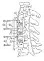
- FIG. 1is a partial side view of a human spine illustrating anteriorly discs between various spinal bones
- FIG. 2is a partial side view of the spinal column shown in FIG. 1 illustrating several of the discs removed, for example, after surgical procedure;
- FIG. 3is a partial side view of the human spine with the housings according to one embodiment of the invention situated therein;
- FIG. 4is a partial side view of the human spinal column illustrating graft material being inserted anteriorly into the housing;
- FIG. 5is a partial exploded side view of the embodiment shown in FIG. 1-4 illustrating a cover and a plurality of screws which will secure the cover to the spinal column;
- FIG. 6is a side view similar to FIG. 5 illustrating after the cover has been mounted to the spinal column;
- FIG. 7is an exploded view of the device shown in FIG. 6 , illustrating a plurality of housings and a single cover for use with covering the plurality of housings;
- FIG. 8is partial side view illustrating an elongated housing and cover used during a vertebrectomy procedure
- FIG. 9is a partial side view of the spinal column illustrated in FIG. 8 showing the elongated housing situated between adjacent spinal bones in a single cover to be affixed to those spinal bones;
- FIG. 10is an exploded view of the circle area shown in FIG. 8 ;
- FIG. 11is a exploded view of the elongated housing illustrated in FIGS. 8 and 9 and the cover and screws associated therewith;
- FIG. 12is a partial fragmentary view of the cover and housing after the cover has been situated between a pair of rails associated with the housing;
- FIG. 13illustrates a partial side view of an embodiment showing a plurality of housings of different sizes used with a single cover
- FIG. 14is an exploded view of the housings and cover illustrated in FIG. 13 ;
- FIG. 15is a partial anterior side view a human spine illustrating the discs between various spinal bones
- FIG. 16is a partial anterior view of the spinal column shown in FIG. 1 illustrating several of the discs removed, such as by surgical procedure;
- FIG. 17is a partial anterior view of the human spine with the housings according to one embodiment of the invention situated therein;
- FIG. 18is a partial anterior view of the human spinal column illustrating graft material being inserted anteriorly into the housing;
- FIG. 19is a partial exploded anterior view of the embodiment shown in FIG. 1-4 illustrating a cover and a plurality of screws for securing the cover to the spinal column;
- FIG. 20is a anterior view similar to FIG. 5 illustrating the cover mounted to the spinal column;
- FIG. 21is a fragmentary view illustrating various features of the cover
- FIG. 22is another fragmentary view of the cover after the screws are mounted and the locking mechanism retains the screws therein;
- FIG. 23is a fragmentary sectional view of the embodiment shown in FIG. 22 illustrating various features of the locking mechanism
- FIG. 24is a schematic view of a process or method in accordance with an embodiment of the invention.
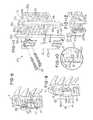
- FIG. 25illustrates another embodiment of the invention without crossbars or migration preventers
- FIG. 26is a view of another embodiment of the invention showing the crossbars integrally formed in the housing and without migration preventers;
- FIG. 27is a view illustrating a plurality of migration preventers, without any crossbars
- FIG. 28is a view illustrating a housing with a plurality of projections which cooperate with the cover to prevent the housing from migrating anteriorly;
- FIG. 29is another view of the housing illustrating a plurality of removable crossbars without any migration preventers
- FIG. 30illustrates another embodiment of the invention, similar to the devices illustrated earlier relative to FIG. 1-20 showing details of the cross bars and notches for receiving them;
- FIG. 31is a view of a housing having walls having recessed areas for receiving the cover
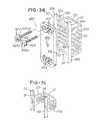
- FIG. 32is a view of another embodiment of the invention showing the plurality of fasteners or screws in an unlocked position
- FIG. 33is a view of the fasteners or screws shown in FIG. 32 in a locked position
- FIG. 34is a view taken along the line 34 - 34 in FIG. 32 ;
- FIG. 35is a view taken along the line 35 - 35 in FIG. 33 ;
- FIG. 36is an exploded view of the other embodiment of the invention with the locking screws illustrated in FIGS. 32-35 ;
- FIG. 37is a perspective view of another embodiment of the invention.
- FIG. 38is a front view of the embodiment shown in FIG. 37 ;
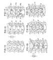
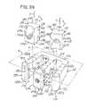
- FIG. 39is a view illustrating a cage and a plurality of planar members or plate inserts
- FIG. 40is a view illustrating the sliding movement of the plate members in the cage
- FIG. 41is a view illustrating the plate members in a home position
- FIG. 42is a plan view of the embodiment shown in FIG. 41 ;
- FIG. 43is a plan view of the embodiment shown in FIG. 41 without the plate elements
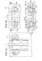
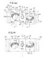
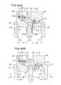
- FIG. 44Ais a sectional view taken along the line 44 A- 44 A in FIG. 43 ;
- FIG. 44Bis a sectional view illustrating the insertion of the plate elements into the cage
- FIG. 44Cis a view similar to FIG. 44B illustrating the lateral deflection (as viewed in the figure) of the leg portions;
- FIG. 44Dis a sectional view taken along the line 44 D- 44 D in FIG. 42 after the plate elements are locked in the cage;
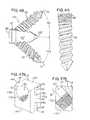
- FIG. 45is a plan view of one of the sliding plate elements
- FIG. 46is a front view of the plate element shown in FIG. 45 ;
- FIG. 47Ais a perspective view of the plate element shown in FIGS. 45 and 46 .
- FIG. 47Bis a sectional view illustrating a tapered and threaded bore in the plate element shown in FIG. 47A ;
- FIG. 48is a side view of an implant having the plates and screws therein illustrating the predetermined angles at which the screws traverse through the cage;
- FIG. 49is a view of a screw adapted to be used in the cage.
- FIGS. 50-52illustrate various interconnecting joints that may be used in the illustrating being described
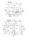
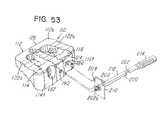
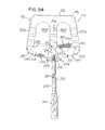
- FIG. 53is a view of a tool that locks the plates to the cage during insertion and without obstructing access to any aperture in the plate;
- FIG. 54is a perspective view showing the tool in FIG. 53 mounted on the cage and securing the plates therein.
- FIG. 1a partial side view of a patient or person P is shown having a spinal column S and a plurality of spinal bones, such as vertebrae, 10 , 12 , 14 and 16 .
- a discsuch as discs 18 , 20 and 22 in FIG. 1 , is located between adjacent pairs of spinal bones (e.g., between bones 10 and 12 , 12 and 14 , and 14 and 16 ).
- a spinal fusion proceduresuch as a discectomy
- the discs 18 , 20 and 22may be removed so that adjacent vertebrae may be fused together
- FIG. 2illustrates a fragmentary view of the spinal column S shown in FIG. 1 , with the discs 18 , 20 and 22 removed. It should also be understood that during another surgical procedure, such as a vertebrectomy, it may be desired to remove part or all of one of the spinal bones 10 - 16 , as illustrated in FIG. 13 . In this type of neurological procedure, it may also be desired to fuse adjacent spinal bones together for reasons that are conventionally known. This invention provides means for facilitating and performing such procedures. For ease of illustration, FIGS. 15-20 provide corresponding anterior views to the side views shown in FIGS. 1-6 , respectively.
- a spinal fusion system 24is provided for use as a prosthetic implant during a neurological procedure such as the aforementioned vertebrectomy or discectomy.
- a plurality of receiving areas 26 , 28 and 30are defined by the areas between the surfaces of adjacent spinal bones 10 , 12 , 14 and 16 .
- the area 26is bounded in part by the surface 10 a of spinal bone 10 and surface 12 a of spinal bone 12 .
- area 28is partially bounded by surface 12 b of spinal bone 12 and surface 14 a of spinal bone 14
- area 30is bounded by surface 14 b of spinal bone 14 and surface 16 a of spinal bone 16 .
- the spinal fusion system 24comprises a housing 32 dimensioned to be situated or received between adjacent spinal bones, such as bones 10 and 12 .
- a housing 32is situated in each of the plurality of receiving areas 26 , 28 and 30 , as illustrated in FIGS. 3-4 .
- Each housing 32cooperates with adjacent spinal bones to define a graft area, such as areas 34 , 35 and 36 in the view illustrated in FIG. 17 , for receiving graft material 38 ( FIGS. 4 and 18 ).
- the graft material 38is situated in the areas 34 , 35 and 36 after placement of the housing 32 .
- the housing 32is generally U-shaped as shown.
- the housing 32comprises a well 33 defining multiple sides and comprising a predetermined shape selected to cause the graft material to be formed into a multi-sided fused coupling between adjacent spinal bones, such as bones 10 and 12 in FIG. 3 .
- the housing 32could define a shape other than rectangular, such as semi-circular, oval or other suitable shape as may be desired.
- the housing 32comprises a first wall 32 a , a second wall 32 b and a third wall 32 c joining the first wall 32 a and the second wall 32 b .
- One or more of the walls 32 a - 32 cmay comprise a plurality of holes or apertures 40 which facilitate the fusing process.
- the apertures 40also permit visualization of graft material 38 on x-rays.
- the predetermined shape defined by the spinal fusion system 24may provide a fused multi-sided plug of fusion material 38 having a height H ( FIGS. 14 and 16 ) of at least two millimeters, but typically less than approximately 180 millimeters.
- This height Hmay vary depending on the vertical size or height H (as viewed in FIG. 16 ) of the areas 26 - 30 to be filled.
- the height H of the area 26generally corresponds to a height H 1 ( FIG. 1 ) of a disc, such as disc 18 .
- the fusion material 38FIG. 18
- the fusion system 24 and housing 32will define a height that generally corresponds to the dimension or height H ( FIG. 9 ) to be traversed.
- the dimensions of the generally U-shaped housing 32 of the spinal fusion system 24is selected depending on the size of the area 26 - 30 to be filled and the environment or application in which the spinal fusion system 24 is used. In general, the width and depth of the housing 32 will be approximately 9-20 millimeters and 7-20 millimeters, respectively.
- the spinal fusion system 24further comprises a cover 42 comprising a plurality of apertures 44 that receive a plurality of screws 46 , respectively, which are screwed directly into the spinal bones 10 and 16 , as illustrated, for example, in FIGS. 5-6 .
- the housing 32comprises a first rail, channel wall or wall portion 48 and a second rail, channel wall or wall portion 50 which cooperate to define a channel area 52 for receiving the cover 42 .
- the sides 42 a and 42 bbecome associated with the sides 48 a and 50 a .
- the cover 42is not permanently secured to the housing 32 after it is received in channel area 52 . This feature permits the housing 32 to migrate or float relative to the cover 42 even after the cover 42 is fixed to one or more of the spinal bones 10 - 16 as illustrated in FIGS. 6 and 20 .
- the edges 42 a and 42 b of cover 42 and sides 48 a and 50 amay be beveled and complementary to facilitate locating and mating engagement between the cover 42 and housing 32 .
- the cover 42is situated between the walls or rails 48 and 50 , as illustrated in FIGS. 6 and 19 .
- the screws 46may then be used to secure the cover 42 to one or more of the spinal bones 10 - 16 as illustrated in FIGS. 6 and 20 .
- a feature of the inventionis that the cover 42 facilitates aligning the housings 32 in a substantially co-lineal or relatively aligned position relative to each other and to the spinal bones 10 - 16 , as illustrated in FIGS. 6 , 19 and 20 .
- the floating cover 42allows limited, controlled settling of the cages or housings 32 in the vertical plane with respect to the cover 42 .
- the cover 42also provides means for providing a mechanical fixation of the adjacent spinal bones 10 - 16 relative to each other.
- the coveris multi-functional in that it not only covers the opening of any graft areas, such as area 34 ( FIG. 17 ), but it also secures and retains the spinal bones 10 - 16 in a fixed spatial relationship relative to each other and relative to the housings 32 .
- the cover 42may be fixed to one or more of the spinal bones 10 - 16 as may be desired to accomplish either of the aforementioned functions.
- the walls 48 and 50further define projections 48 b , 48 c , 50 b and 50 c as shown.
- the projections 48 b , 48 c , 50 b and 50 cprovide a plurality of migration preventers for preventing the housing 32 from migrating posteriorly in the direction of arrow A ( FIG. 3 ) toward the spinal cord S or other neurological elements after the housing 32 is situated between the adjacent spinal bones 10 - 16 as illustrated.
- the migration preventers 48 b , 48 c , 50 b and 50 cenable a surgeon to locate each housing 32 between adjacent spinal bones, such as spinal bones 10 - 16 in FIG.
- the migration preventers 48 b , 48 c , 50 b and 50 cengage the surface 10 a of spinal bone 10 and migration preventers 48 b , 48 c , 50 b and 50 c engage the surface 12 a of spinal bone 12 .
- the migration preventers 48 b , 48 c , 50 b and 50 cfacilitate preventing the wall 32 c from being over-inserted by the surgeon or from being over-inserted to a point where it engages the spinal cord S or other neurological elements.
- the spinal fusion system 24further comprises at least one migration stop or crossbar 60 as illustrated in FIGS. 11 , 12 , 29 and 30 .
- the crossbar 60may be either integrally formed in housing 32 , as shown in FIG. 26 , or separate as illustrated in FIGS. 7 , 11 , 12 , 14 , 29 and 30 , for example.
- the surface 60 a of crossbar 60engages and cooperates with surface 42 c of cover 42 to prevent anterior migration in the direction of arrow B).
- the spinal fusion system 24 of the embodiment being describedprovides means for preventing insertion of the housing 32 to a point where it might engage the spinal cord S ( FIG.
- a plurality of the migration stops or cross bars 60may be used alone or in combination with the migration preventers 48 b , 48 c , 50 b and 50 c . It should be understood that the stops 60 could be detachable, as shown in FIG. 26 , or they could be integrally formed in housing 32 (as shown in FIG. 26 ). Also, these cross bars 60 may be removably received in the notched receiving areas 94 ( FIGS. 29-30 ). For example, in anatomy that provided limited space, the surgeon may elect not to use a housing with cross bars 60 or use a housing that does not have integrally formed cross bars.
- the system 24further comprises a system or means for preventing retraction or back out of the screws 46 after they are screwed into the spinal bones 10 - 16 in order to secure the cover 42 thereto.
- the spinal fusion system 24 of the present inventionmay be used with conventional screw lock devices or with a unique locking mechanism and system, which will now be described relative to FIGS. 21-23 .
- the spinal fusion system 24 and, more particularly, cover 42may be provided with at least one or a plurality of resilient detents 62 which are generally L-shaped as shown and are resilient so that they can move laterally in the direction of double arrow C in FIGS. 21-22 towards and away from a home position ( FIG. 21 ) to permit the screws 46 first received in the apertures 44 , and, second, locked into the cover 42 .
- the screws 46may be screwed into a spinal bone, such as spinal bone 10 , and when a screw head 46 a of the screw 46 engages a detent portion 62 a of the resilient detent 62 , the resilient detent 62 moves in a direction away from the apertures 44 until the screw head 46 a clears the portion 62 a . After a top surface 46 b of the screw head 46 a has cleared the bottom surface 62 a 1 (as viewed in FIG.
- portion 62 athe resilient detent 62 moves back toward aperture 44 to the home position until the portion 62 a and surface 62 a 1 are operatively positioned over surface 46 b of screw 46 , thereby retaining and preventing the screws 46 from backing out of the cover 42 and thereby preventing the screws 46 from backing out of the spinal bone 10 .
- the platecomprises a first surface 50 d ( FIG. 23 ) and a second surface 50 e .
- the plate memberfurther comprises a seat or edge 50 f ( FIG. 21 ) associated with the first surface 50 d and the detent 62 a associated with the second surface 50 e.
- the components of the spinal fusion system 24such as the housing 32 , first channel wall portion 48 and second channel wall portion 50 , crossbar 60 , cover 42 and screws 46 may be made of any desired composition or material such as a polymer, composite polymer, titanium, stainless steel, carbon fiber or other suitable material.
- FIG. 22A method for fusing spinal bones together will now be described relative to FIG. 22 . It should be understood that this procedure may be used during a vertebrectomy or discectomy or other neurological procedure during which it is desired to fuse spinal bones together.
- the embodimentwill be described as used during a discectomy procedure during which the discs 18 - 22 ( FIG. 1 ) are removed so that spinal bones 10 - 16 may be fused together.
- the procedurebegins by situating a patient P on an operating table (not shown) and providing an appropriate incision as conventionally known to expose the spinal bones such as the bones 10 - 16 illustrated in the side view shown in FIG. 1 and in the anterior view illustrated in FIG. 15 . (Block 70 in FIG. 22 ).
- the vertebrae or discssuch as discs 18 - 22 in FIGS. 1 and 15 , are surgically removed revealing the areas 26 - 30 in FIGS. 2 and 16 .
- the housings 32are inserted in the direction of arrow A ( FIG. 3 ) into the areas 26 , 28 and 30 until the migration preventers 40 b , 48 c , 50 b and 50 c engage the surfaces of the spinal bones 10 - 16 , such as the surfaces 10 a and 12 a illustrated in FIG. 3 . (Block 74 in FIG. 22 ).
- the migration preventersfacilitate preventing inserting the housing 32 to a point which would cause the wall 32 c to engage the spinal column S.
- the housing 32cooperates with adjacent spinal bones, such as bones 10 and 12 to define the graft receiving area or cavity 34 in which the graft material 38 ( FIG. 4 ) may be inserted.
- these graft areas 34 - 36may comprise a shape which is generally rectangular, as defined by the shape of the housing 32 , but it could comprise another shape by simply providing a housing 32 having a different predetermined shape.
- the housing 32may be provided in a circular or arcuate shape in which case the graft area 34 would define a generally circular or arcuate area, which would cause the graft material to form a similar shape.
- Other curved or multi-sided shapesmay be defined by providing an appropriately or correspondingly shaped housing 32 , depending on the selected or desired shape that the physician would like the fused graft material 38 to assume after it has fused to the adjacent spinal bones.
- the cover 42is situated in the slot or area 52 defined by the walls 48 and 50 .
- the cover 42facilitates covering the openings, such as openings 34 a and 36 a of the graft areas 34 and 36 , respectively.
- the surgeonsecures the cover 42 to one or more of the bones, as illustrated in FIGS. 5-6 and 19 - 20 and then closes the patient (Block 80 ).
- a feature of the inventionis that it provides a fixing system for fixing the location of the bones 12 - 16 relative to each other. Simultaneously, the system 24 permits the housing 32 to “float” between adjacent bones, such as bones 10 and 12 in FIGS. 3 and 6 . This is advantageous for reasons mentioned earlier herein.
- Another advantage on this feature of the inventionis that if it is necessary to operate on the same patient at a later time (Block 82 in FIG. 24 ) and, for example, add one or more housings 32 in order to fuse other spinal bones together, then the cover 42 can simply be removed at a later time, another discectomy or vertebrectomy performed and another housing 32 inserted.
- Another cover 42may then be used to seal the additional housing 32 after it is situated in the manner described herein.
- this inventionprovides a system and method, which is flexible and will permit the addition or insertion of additional housings 32 of the same or different sizes during a second operating procedure as illustrated in Block 82 .
- FIGS. 1-8 and 15 - 20illustrate the general procedure and use of the invention in an illustrative discectomy wherein three discs are removed, replaced with housing 32 , and graft material 38 inserted as described, and cover 42 situated and mounted as described herein.
- three discs 18 - 22are removed and the spinal bones 12 - 16 are fused together using the system and method as shown and described. It should be appreciated, however, that this system and method may be used with fewer or more housings 32 and with one or a plurality of covers 42 as may be desired or required.
- the housings 32may comprise a different dimension or different height H ( FIG. 14 ) to span a greater area, such as the area H 4 illustrated in FIGS. 13 and 14 .
- FIGS. 13 and 14illustrate a vertebrectomy wherein the spinal bone 12 has been removed along with the disc between spinal bones 14 and 16 . This provides areas 80 and 81 in which an elongated housing 32 ′, such as the housing 32 ′ illustrated in FIG. 14 may be inserted.
- graft areas 82 and 84are provided for receiving the graft material 38 .
- the cover 42would have a corresponding elongated shape for fixing the bones 10 and 14 together and for covering both openings 82 and 84 or housings 32 and 32 ′.
- the inventionmay be used in a multitude of procedures, such as a vertebrectomy ( FIGS. 8 and 9 ), discectomy ( FIGS. 1-7 , 13 - 20 , or even a combination of a vertebrectomy and discectomy as illustrated in FIGS. 13-14 .
- a combination of different sizes of housings 32 and covers 42may be used as shown. Although it is preferred that a single cover 42 be used, it may be desired in some applications to use multiple covers 42 , such as where the removed discs are not adjacent.
- the housings 32comprise the crossbar 60 which cooperate with the cover 42 to prevent anterior migration of the housing after the screws 46 are secured to the spinal bones as illustrated in FIGS. 6 , 9 and 13 .
- FIGS. 25-30illustrate other embodiments of the invention.
- a generally U-shaped housing 32is provided without the walls 48 and 50 or crossbar 60 .
- This embodimentmay be useful. This may be useful if it were desired to insert housing 32 in local anatomy so that it could be loaded from the side or laterally, rather than anteriorly, as previously described.
- a housing 32 ′′′is provided with the crossbars 60 , but without the walls 48 and 50 . In this embodiment it may be useful to use such a housing design when the local anatomy provides limited space.
- FIG. 27illustrates yet another embodiment of the invention illustrating a housing 32 that is provided with a plurality of protrusion 86 , 88 , 90 and 92 that do not span completely between the walls 32 b or 32 a together but yet provide the protrusions 86 - 92 which will engage the cover 42 if the housing attempts to migrate anteriorly as described earlier herein.
- FIGS. 1-24 , 29 and 30show embodiments of the invention where the crossbars 60 are not integrally formed with the housing 32 , but received in the notched areas 94 as shown. As mentioned earlier, the crossbars 60 may be separate or may be integrally provided with the housing 32 . Providing detachable crossbars 60 , such as is shown in the embodiments illustrated in FIGS.
- housing 32 and cover 42may be made of titanium, polymer or a bioresorbable material.
- FIG. 31illustrates the walls 48 and 50 having notched areas 49 and 51 for receiving the cover 42 which is dimensioned to fit, thereby eliminating the need for cross bars 60 .
- FIGS. 32-36illustrate another embodiment of the invention.
- those parts that are the same or similar to the parts illustrated in FIGS. 1-30are identified with the same part number, except that the parts in FIGS. 31-36 have an apostrophe (“'”) mark added thereto.
- 'apostrophe
- the cage system 24comprises a cover 400 for situating in the channel area 52 ( FIG. 11 ) to facilitate preventing interior migration of the graft material 38 .
- a locking system, means and methodare provided for retaining the cover 400 on the housing 32 .
- the locking system 402comprises a plurality of screws, fastening means or fasteners 404 , 406 , 408 and 410 that are received in openings, such as openings 405 in the cover plate 400 as shown.
- the fasteners 404 - 410comprise a plurality of female openings or slots 404 a , 406 a , 408 a and 410 a for receiving a tool, such as a hex wrench for tightening and loosening the fasteners 404 - 410 .
- the fasteners 404 and 408comprise a head 404 b and 408 b that have a planar or flat portion 404 b 1 and 408 b 1 as shown.
- the fasteners 408 and 410each comprise threads or a threaded portion, such as threads or portions 408 c and 410 c of fasteners 408 and 410 , respectively.
- a distance or small radius D 1 between center C 1 and flat portion 408 b 1 in FIG. 34is smaller than the distance or large radius D 2 measured by the distance between center C 1 and wall 408 b 2 in FIG. 35 .
- the difference in the distances D 1 and D 2facilitates defining a cam surface or lobe on the wall 408 b 2 whose use and purpose will be defined later herein.
- one or more of the heads 404 b , 406 b , 408 b and 410 bmay comprise an indicia, such as a grind mark or other indicator 412 and 414 ( FIG. 32 ), to facilitate and assist a user, such as a doctor, to identify the small radius portion D 1 during a surgical procedure.
- the indicia 412 and 414facilitate defining the surface associated with the flat portion, such as portion 404 b 1 .
- the locking system of the present inventionmay comprise eccentric fasteners of screws having eccentric heads (i.e., where a head center is offset from a thread axis) and fasteners that are used with non-eccentric fasteners.
- fasteners 404 and 408may comprise the aforementioned eccentric, while adjacent fasteners 406 and 410 , respectively, may be non-eccentric fasteners or screws.
- the small radius portion D 1permits the adjacent fastener or screw such as screw 410 , whether it has an eccentric or not, to be turned when the small radius portion D 1 or flat portion 408 b 1 is situated in opposed relationship to the adjacent screw (as illustrated in FIGS. 32 and 34 ).
- FIG. 34illustrates that when the fasteners are aligned such that the indicia 414 are aligned as illustrated in FIG. 32 , a gap G exists between the portions 408 d 1 and wall 410 d of screw 410 as shown.
- the gap Gpermits either or both of the fasteners 408 and 410 to rotate in either a counter-clockwise or clockwise direction during fastening and unfastening of the fasteners to the vertebrae as described earlier herein with the prior embodiments.
- the fasteners 404 - 408are placed in the cover and aligned as illustrated in FIG. 32 .
- the fasteners 404 - 408are rotated and screwed into vertebrae 10 in a clockwise direction until it is seated.
- These fasteners 404 and 408are then “backed out” less than a full turn until flat portions 404 b 1 and 408 b 1 are aligned as shown in FIG. 32 .
- the surgeonmay use the indicator 412 and 414 to perform this alignment.
- This alignmentpresents the gap G ( FIG. 34 ), which permits the fastener 410 to be rotated in a clockwise direction until completely screwed into vertebrae 10 .
- the adjacent fastener or screw( 406 for the 404 - 406 pair and 410 for the 408 - 410 pair) is inserted into opening 405 in cover 400 and in FIGS. 32 and 34 until they are fully seated into the vertebrae 10 .
- the fastener 408is rotated in a clockwise direction with a tool, such a hex wrench (not shown) until it is fully seated into the vertebrae 10 .
- the fastener 408is again rotated in the clockwise direction (as viewed) until the large radius portion D 2 and the wall portion 408 b 2 engages and comes against the wall 410 b of the fastener 410 .
- fasteners 404 - 410when the fasteners 404 - 410 are secured in the locked position in the manner described, they facilitate retaining themselves in the locked position. For example, if fastener 410 begins to rotate in a counterclockwise direction (as viewed in FIG. 33 ) it will cause fastener 408 to rotate in a clockwise direction which, in turn, causes fastener 408 to tighten and resist the counterclockwise rotation of fastener 410 . If fastener 410 would rotate, fastener 408 would screw deeper into the vertebrae 10 .
- FIG. 36is an illustration similar to FIG. 11 showing the orientation and alignment of the cover 400 and fasteners 404 - 410 to the housing 32 .
- the various embodiments of the invention illustrated in FIGS. 1-36provide a system and method for inserting graft material 38 into a graft area 34 and 36 ( FIG. 17 ) to fuse a plurality of bones such as bones 10 - 18 together.
- the system and methodalso provide means for fixing the bones 10 - 18 relative to each other, while permitting the housing 32 to cooperate with adjacent bones 10 - 18 to define a graft area 34 and 36 ( FIG. 17 ) and to also float relative to the cover 42 .
- the locking system illustrated in FIGS. 21-23further facilitates providing a locking system that does not require the use of any tools, yet prevents back out of the screws 46 .
- FIGS. 37-54Another embodiment of the invention is shown in FIGS. 37-54 .
- a spinal implant or system 110 and its various components described hereinare shown.
- the spinal implant or system 110is situated in an intervertebral space or disc area (not shown) between a first vertebra (not shown) and a second vertebra (not shown).
- the spinal implant or system 110is used during a fusion procedure.
- the spinal implant or system 110comprises a cage 112 , a plurality of plate elements, such as a first plate element 114 and a second plate element 116 , that are slidably, movably or detachably secured to the cage 112 .
- a first plate element 114 and 116for ease of illustration and discussion, an exemplary embodiment will be shown and described with respect to the first and second plate elements 114 and 116 , but it should be understood that more or fewer plate elements (not shown) may be used.
- each of the plurality of plates elementssuch as the first and second plate elements 114 and 116 , and the cage 112 are adapted to permit the first and second plate elements 114 and 116 to move independently on the cage 112 in the manner described herein.
- the first plate element 114comprises an axis A ( FIG. 39 )
- the second plate element 116comprises an axis B.
- the first and second plate elements 114 and 116 in the illustration and the cage 112are adapted to permit the first and second plate elements 114 and 116 to move in the direction of double arrow C and double arrow D, respectively, as illustrated in FIG. 39 .
- the axial movement of the first and second plate elements 114 and 116is generally perpendicular to an imaginary plane P ( FIG. 39 ) in which the cage 112 lies. Also, note that the axis of movement of the first and second plate elements 114 and 116 , along their respective axes A and B, is generally parallel with respect to each other.
- the cage 112is W-shaped and comprises a first leg portion 120 , a second leg portion 122 and a third leg portion 124 that are generally parallel and integral or monolithic with a first wall 112 a of the cage 112 .
- the cage 112is shown as being generally W-shaped, it should be understood that other shapes or configurations could be provided depending on the number of leg portions used to define the cage 112 and the number of plate elements to be inserted therein.
- the first wall 112 ais a posterior or rear wall 126 that gets inserted first in the disc area (not shown) between the first vertebra and second vertebra.
- the first, second and third leg portions 120 - 124are integrally and monolithically formed with the first wall 112 a as shown.
- the first leg portion 120comprises a first side wall or surface 120 a and a generally opposing bottom surface 120 b; the second leg portion 122 comprises a top surface 122 a and a generally opposing bottom surface 122 b; and the third leg portion 124 comprises a top surface 124 a and a generally opposing bottom surface 124 b .
- the top surfaces 120 a , 122 a and 124 a and the opposing bottom surfaces 120 b , 122 b and 124 bmay be serrated, coated, treated or otherwise adapted to enhance the engagement and retention of the cage 112 with the first vertebra and the second vertebra, respectively.
- At least one, a plurality, or all of the first, second or third leg portions 120 , 122 and 124are elastic or resilient or are otherwise adapted so that they can flex and move, for example, in the direction of arrows G and H in FIGS. 43 and 44B .
- at least one or both of the first leg portion 120 or third leg portion 124may flex or move laterally or away from the third leg portion 124 in response to the longitudinal movement or insertion of the first and second plate elements 114 and 116 into the cage 112 .
- first leg portion 120 and the second leg portion 122This enables the first leg portion 120 and the second leg portion 122 to move in the direction of arrows G and H, respectively, (i.e., to the left and right as viewed in the FIG. 40 ) during insertion of the first plate element 114 and second plate element 116 into the cage 112 .
- first plate element 114 and second plate element 116may be inserted separately or independently or could be inserted substantially simultaneously as illustrated in FIG. 40 .
- the first leg portion 120comprises a first side wall or surface 120 c that is generally opposed to a second side wall or surface 124 c of the third leg portion 124 as shown.
- the third leg portion 124further comprises a third side wall or surface 124 d that generally opposes a fourth side wall or surface 122 c of the second leg portion 122 .
- the first side wall or surface 120 a and second side wall or surface 124 care generally opposed to provide a first window area 130
- the third side wall or surface 124 dis generally opposed to the fourth side wall or surface 122 c to define and provide a second window area 132 .
- the first window area 130receives the first plate element 114 and the second window area 132 receives the second plate element 116 as described in more detail later herein.
- the first plate element 114comprises a first plate side 114 a , a second plate side 114 b , a top surface 114 c and a bottom surface 114 d , as best illustrated in FIG. 39 .
- the second plate element 116comprises a third plate side 116 a , a fourth plate side 116 b , a top surface 116 c and a bottom surface 116 d . Note that when the first plate element 114 is inserted into the first window area 130 in a manner described in more detail later herein, the first plate side 114 a engages and becomes associated with the first side wall or surface 120 c as illustrated in FIGS. 40-42 .
- the third plate side 116 abecomes engaged to or associated with the second side wall or surface 122 c of the second leg portion 122 and the fourth plate side 116 b becomes operatively associated with or engaged to the third side wall or surface 124 d of the third leg portion 124 , as best illustrated in FIGS. 39 , 40 , 43 and 44 A- 44 D.
- the spinal implant or system 110further comprises a lock, guide or movement controller 134 and 136 for locking the first plate element 114 and second plate element 116 , respectively, to the cage 112 .
- the cage 112 and the first and second plate elements 114 and 116are adapted to permit controlled motion of the first and second plate elements 114 and 116 in the cage 112 and with respect to each other.
- the cage 112 and the first and second plate elements 114 and 116are adapted to permit controlled motion of the first and second plate elements 114 and 116 after they are received in the cage 112 .
- the motionis controlled motion in the axial directions of arrows C and D ( FIG.
- the locks 134 and 136also control motion of the first and second plate elements 114 and 116 in the direction of double arrow E ( FIG. 42 ) and double arrow F, respectively.
- the functions and adaptations for providing and permitting the controlled motion of the first and second plate elements 114 and 116 within the cage 112may be separate from or combined with the locking function mentioned earlier herein. In the illustration being described, however, both the locking and controlled motion functions are incorporated in the locks, guides or movement controllers 134 and 136 which will now be described.
- first plate side 114 a of the first plate element 114engages and becomes operatively associated and generally opposed to the first side wall or surface 120 c of the first leg portion 120 and defines a first joint 140 ( FIG. 40 ).
- second plate side 114 bbecomes operatively associated and generally opposed to the second side wall surface 124 c of the third leg portion 124 to define a second joint 142 .
- fourth plate side 116 bbecomes operatively associated and generally opposed to the third side wall or surface 124 d to define a third joint 145
- the third plate side 116 aengages and becomes associated with and generally opposed to the fourth side wall or surface 122 c to define a fourth joint 147 .
- At least one or a plurality of the pairs of joints 140 , 142 and joints 145 , 147are interfitting or interlocking joints for permitting the first and second plate elements 114 and 116 to move relative to the cage 112 after the first and second plate elements 114 and 116 are mounted on or in the cage 112 .
- the at least one or a plurality of the interfitting joints 140 , 142 and 145 , 147both retain and lock the first and second plate elements 114 and 116 in the cage 112 and also are adapted to permit the controlled motion of the first and second plate elements 114 and 116 in the directions of double arrows C and D ( FIG. 39 ) and double arrows E and F ( FIG. 42 ).
- the at least one or a plurality of the interfitting joints 140 , 142 and 145 , 147permit, for example, sliding movement of each of the first and second plate elements 114 and 116 and on the cage 112 .
- the sliding movement of each of the first and second plate elements 114 and 116is axial or longitudinal movement in their respective axes A and B, as illustrated in FIGS. 39 and 40 .
- the sliding movementis generally parallel to an axis CA ( FIGS. 40 and 41 ) of the cage 112 .
- FIGS. 47A-47Bdetails of the locks, guides or movement controllers 134 and 136 will now be described.
- the first plate element 114will be described, with it being understood that the second plate element 116 is constructed substantially identically, but is situated in the cage 112 in a opposite orientation (i.e., upside down relative to the first plate element 114 in FIG. 39 ) when it is inserted in the cage 112 .
- the first plate element 114comprises a first elongated rail, boss or projection 144 that projects or extends from the first plate side 114 a and is received in a complementary mating receiving area, groove, channel, slot or notch 149 ( FIGS. 43-44D ) in the first side wall or surface 120 c of the first leg portion 120 when the first plate element 114 is slidably received between the first and third leg portions 120 and 124 .
- the second plate side 114 bcomprises a first rail, boss or projection 146 and a second rail, boss or projection 148 as shown. Note that these projections lie in a common plane P 1 ( FIG. 45 ) and have a common axis.
- the first rail, boss or projection 146comprises an end or step 146 a and the second rail, boss or projection 148 comprises an end or step 148 a .
- the ends or steps 146 a and 148 acooperate to define a receiving area, groove, channel, slot or notch 150 ( FIG. 46 ) for receiving a mating portion or intermediate area 160 whose function will be described later herein.
- the first plate element 114is slidably received between the first and third leg portions 120 and 124 , the first rail, boss or projection 146 and the second rail, boss or projection 148 are received in the grooves, channels, slots or notches 152 and 154 , respectively, as best illustrated in FIG. 44A .
- the first and second plate elements 114 and 116may be guided or inserted into the cage 112 from the top or bottom, such as in the direction of arrow X ( FIG. 40 ), or from a bottom or in the direction of arrow Y.
- the rails, bosses or projections 144 , 146 and 148mate with and are received in their respective groove, channel, slot or notch 149 , 152 and 154 , respectively.
- the rails, bosses or projections 144 , 146 and 148have a cross-sectional radius or curvature that complements the shape of the grooves, channels, slots or notches 149 , 152 and 154 .
- the ends 152 a and 154 a( FIG.
- first or second plate elements 114 or 116are inserted, for example, from a bottom of the cage 112 (as viewed in FIG. 44A ), then its respective rails, bosses or projections 144 and 146 engages an end 154 a ( FIG. 44A ) of the groove, channel, slot or notch 154 so that, for example, when the second plate element 116 is driven in the direction of arrow Y ( FIG. 40 ) and further into the cage 112 , the movement causes the second leg portion 122 to deflect in the direction of arrow H ( FIG. 44B ).
- the rail, boss or projection 146This enables the rail, boss or projection 146 to slide over the intermediate area 160 until the rails, bosses or projections 146 and 148 are received in the grooves, channels, slots or notches 152 and 154 , respectively.
- the second leg portion 122is elastic and resilient so that as the second plate element 116 is driven into the cage 112 , it is deflected or moves laterally in the direction of arrow G ( FIGS. 44B-44D ) until the rails, bosses or projections 146 and 148 are received in their respective grooves, channels, slots or notches 152 and 154 , respectively.
- the rails, bosses or projections 146 and 148each have a longitudinal axis that lies in the plane (P 1 ), and the rail, boss or projection 144 lies in plane (P 2 ). Note that these planes P 1 and P 2 are offset and are parallel as shown. The rails, bosses or projections 146 and 148 are offset from the rail, boss or projection 144 .
- the joints 140 , 142 , 145 and 147 at or near the intersection of the first and second plate elements 114 and 116 and the various side walls or surfaces 120 c , 122 c and 124 care adapted to provide both locking of the first and second plate elements 114 and 116 in the cage 112 and also permit controlled motion of the first and second plate elements 114 and 116 in the cage 112 .
- the controlled motion in the illustration being describedis an axial, sliding motion, but it is contemplated that other types of motions and in different directions could be provided and controlled as well.
- the joints 140 , 142 , 145 and 147could be configured to enable the first and second plate elements 114 and 116 to be inserted into the cage 112 in different ways, such as from an anterior, top, bottom or front direction of the cage 112 as shown earlier herein relative to the other embodiments. It is also contemplated that the one or more of the joints 140 , 142 and joints 145 , 147 could comprise different characteristics such as a dovetail ( FIG. 51 ) or a T-shaped boss and groove ( FIG. 52 ). Alternatively, they could comprise the rail and groove illustrated in FIGS. 37-47B and 50 as described earlier herein.
- the rails, bosses or projections 146 and 148could be viewed as a common boss or projection but interrupted.
- the cage 112comprises the grooves, channels, slots or notches 150 , 152 and 154 that are arranged and adapted to complement the location and shapes of the rails, bosses or projections 144 , 146 and 148 , respectively, so that the first and second plate elements 114 an 116 fit snugly and become securely captured, fastened or locked in the cage 112 after they are received in the home position shown in FIG. 41 .
- the cage 112could comprise the bosses or projections with the first and second plate elements 114 and 116 comprising the grooves.
- one or more of the bosses or projection in complementary groovescould be arranged, for example, so that some of the bosses or projections are arranged on the cage 112 and their mating grooves or channels arranged on the first or second plate elements 114 or 116 and some of the bosses or projections arranged on the first or second plate elements 114 and 116 with their mating grooves or channels in the cage 112 .
- the spinal implant or system 110comprises means for securing the cage 112 in the intervertebral space or area (not shown) between the first and second vertebra.
- each of the first and second plate elements 114 and 116comprise internal walls 170 and 172 ( FIG. 40 ), respectively, each having female threaded areas or portions 170 a and 172 a that receive a screw 178 having mating male threads 180 ( FIG. 49 ). This is illustrated in FIG. 47B .
- the first and second plate elements 114 and 116are generally mirror images of each other, except that they are upside down with respect to each other as shown.
- the wall 170defines an aperture 182 and wall 172 ( FIG. 44D ) defines aperture 184 for receiving and guiding the screw 178 along a desired axis, such as axis SA, as the screw 178 travels through the first plate element 114 at a predetermined angle PA 1 as best illustrated in FIGS. 47 and 48 .
- the aperture 182guides and directs the screw 178 to traverse through the first plate element 114 at the predetermined angle PA 1 with respect to the cage 112 .
- this predetermined angle PA 1is on the order of about 30-80 degrees.
- the aperture 184guides the screw 178 in a second predetermined angle PA 2 .
- first and second plate elements 114 and 116are situated in the cage 112 as illustrated in FIGS. 41 and 42 and the cage 112 threadably receives the screws 178 they become automatically positioned and oriented at the predetermined angle PA 1 and a second predetermined angle PA 2 , as illustrated in FIGS. 37 , 38 and 48 . It is contemplated that the first and second predetermined angles PA 1 and PA 2 ( FIG. 48 ) could be the same as illustrated in FIGS. 37 , 38 and 48 , but they could be different.
- the first predetermined angle PA 1 of the first plate element 114 that causes the screw 178 to traverse through the cage 112could be less than or greater than the second predetermined angle PA 2 of the second plate element 116 that causes the screw 178 to traverse through the cage 112 , and vice versa.
- the first and second plate elements 114 and 116may be provided in a kit (not shown) with a plurality of the first and second plate elements 114 and 116 (not shown) having apertures 182 and 184 that define different predetermined angles PA 1 and PA 2 so that a person, such as a surgeon, can select and adapt the spinal implant or system 110 in response to the morphological characteristics of the patient.
- first and second plate elements 114 and 116 in the cage 112causes the axes of their respective apertures 182 and 184 to diverge as illustrated in FIGS. 37 , 38 and 48 .
- each of the threads 170 a and 170 b in the first and second plate elements 114 and 116comprise a corresponding taper so that after the screws 178 are received in each of the apertures 182 and 184 and screwed into bone, the threads 180 of the screws 178 mate with and become locked in the threads 170 a and 170 b .
- the cage 112Given that the first and second plate elements 114 and 116 are mounted in the cage 112 and the screws 178 screwed into bone, the cage 112 , therefore, becomes locked and securely mounted in the intervertebral space between the first and second vertebrae.
- the cage 112comprises a wall 190 ( FIG. 41 ) that defines a threaded tool receiving aperture 190 a for receiving a threaded tool 200 ( FIGS. 53 and 54 ) to facilitate placement of the cage 112 between the first and second vertebrae.
- the tool 200may have a mechanism or means to lock the first and second plate elements 114 and 116 in the cage 112 during the implant insertion process.
- FIGS. 53 and 54show the tool 200 having an internal rod 202 having a threaded end 202 a for threadably engaging the threaded aperture 190 a.
- the tool 200also has a pair of spaced engaging members 206 , 208 for engaging the plates 114 and 116 , respectively, during the insertion process.
- the engaging members 204 and 206could have serrations (not shown) and be integrally formed in the support 210 that is secured to a handle 212 .
- the engaging members 206 and 208could be a polymer, such as rubber or plastic. Alternatively, they could be male projections that are received in female openings (not shown) in the face or front surfaces 114 f , 116 f of the plates 114 and 116 , respectively.
- the tool 200holds the plates 114 and 116 in place in the cage 112 during insertion of the cage 112 in the patient.
- the tool support 210overlaps the faces 114 f and 116 f only enough so that the projections 106 , 108 can engage them.
- the support 210does not interfere with access to the apertures 182 , 184 .
- the screws 178can be inserted into the apertures 182 and 184 and screwed into bone after cage 112 placement and while the tool 200 is mounted on the cage 112 .
- the tool 200does not interfere with the insertion of the screws 178 .
- the pressure that the engaging members 206 , 208 engage or apply to plates 114 and 116 , respectively,can be changed by rotating the handle 214 that is coupled to the threaded end 202 a , thereby enabling the position of plates 114 and 116 to be changed if desired while they are locked in the cage 112 .
- the cage 112is W-shaped. As illustrated in FIGS. 42 and 43 , the first side wall or surface 120 c , second side wall or surface 124 c and wall or surface 112 a 1 of the cage 112 cooperate to define a generally U-shaped graft-receiving area 1000 . Likewise, the fourth side wall or surface 122 c of the second leg portion 122 and the third side wall or surface 124 d and the wall or surface 112 a 2 of the cage 112 define a second graft-receiving area 1002 . Thus, the cage 112 in the illustration being described has a plurality of graft-receiving areas 1000 and 1002 that are divided by the third leg portion 124 in the illustration being shown. It should be understood that more or fewer graft receiving areas could be provided depending upon the configuration of the cage 112 .
- the first and second plate elements 114 and 116may be arranged in the cage 112 as illustrated in FIGS. 41 and 42 and graft material (not shown) inserted and packed into the graft receiving areas 1000 and 1002 .
- the cage 112may be inserted into the intervertebral space between the first and second vertebrae and packed in-situ.
- the first and second window areas 130 and 132open into the graft-receiving areas 1000 and 1002 , respectively, and enable the surgeon to place graft material in-situ during a surgical procedure.
- first and second plate elements 114 and 116are situated in the cage 112 and the screw apertures 182 and 184 used for packing graft material in the graft-receiving areas 1000 and 1002 .
- the screws 178are inserted into the apertures 182 and 184 of the first and second plate elements 114 and 116 , respectively, and then screwed into the first and second vertebrae.
- the first and second plate elements 114 and 116could have different sizes, such as different heights, widths or thicknesses (not shown), along the windows 130 and 132 which could also have different widths.
- first and second plate elements 114 and 116are shown such that they are positioned in the cage 112 at an interior or front area 118 of the cage 112 , it should be understood that they could be situated in one or more of the other surfaces or walls of the cage 112 , such as in the side walls.
- the first and second plate members 114 and 116can “float” by moving vertically independent of the cage body and, importantly, independently of each other. This serves to decouple the axial forces between the cage 112 and first and second plate members 114 and 116 .
- the tool 200 or insertion instrumentmay have the capability to contact or engage the first and second plate members 114 and 116 so that they do not move during the implant insertion process because deployment of the first and second plate members 114 and 116 during insertion may be undesirable.
Landscapes
- Health & Medical Sciences (AREA)
- Orthopedic Medicine & Surgery (AREA)
- Engineering & Computer Science (AREA)
- Biomedical Technology (AREA)
- Neurology (AREA)
- Life Sciences & Earth Sciences (AREA)
- General Health & Medical Sciences (AREA)
- Heart & Thoracic Surgery (AREA)
- Animal Behavior & Ethology (AREA)
- Public Health (AREA)
- Veterinary Medicine (AREA)
- Surgery (AREA)
- Transplantation (AREA)
- Vascular Medicine (AREA)
- Cardiology (AREA)
- Oral & Maxillofacial Surgery (AREA)
- Molecular Biology (AREA)
- Medical Informatics (AREA)
- Nuclear Medicine, Radiotherapy & Molecular Imaging (AREA)
- General Engineering & Computer Science (AREA)
- Mechanical Engineering (AREA)
- Prostheses (AREA)
- Surgical Instruments (AREA)
Abstract
Description
Claims (66)
Priority Applications (3)
| Application Number | Priority Date | Filing Date | Title |
|---|---|---|---|
| US13/409,377US9078706B2 (en) | 2003-09-30 | 2012-03-01 | Intervertebral fusion device utilizing multiple mobile uniaxial and bidirectional screw interface plates |
| EP13405001.2AEP2633836B1 (en) | 2012-03-01 | 2013-01-08 | Intervertebral fusion device utilizing multiple mobile uniaxial and bidirectional screw interface plates |
| US14/793,191US20160000576A1 (en) | 2003-09-30 | 2015-07-07 | Intervertebral fusion device utilizing multiple mobile uniaxial and bidirectional screw interface plates |
Applications Claiming Priority (5)
| Application Number | Priority Date | Filing Date | Title |
|---|---|---|---|
| US10/675,361US7182782B2 (en) | 2003-09-30 | 2003-09-30 | Spinal fusion system and method for fusing spinal bones |
| US10/858,629US7641701B2 (en) | 2003-09-30 | 2004-06-02 | Spinal fusion system and method for fusing spinal bones |
| US11/624,341US7655028B2 (en) | 2003-09-30 | 2007-01-18 | Spinal fusion system and method for fusing spinal bones |
| US12/640,061US8282682B2 (en) | 2003-09-30 | 2009-12-17 | Fusion system and method for fusing spinal bones |
| US13/409,377US9078706B2 (en) | 2003-09-30 | 2012-03-01 | Intervertebral fusion device utilizing multiple mobile uniaxial and bidirectional screw interface plates |
Related Parent Applications (2)
| Application Number | Title | Priority Date | Filing Date |
|---|---|---|---|
| US10/858,629ContinuationUS7641701B2 (en) | 2003-09-30 | 2004-06-02 | Spinal fusion system and method for fusing spinal bones |
| US12/640,061Continuation-In-PartUS8282682B2 (en) | 2003-09-30 | 2009-12-17 | Fusion system and method for fusing spinal bones |
Related Child Applications (2)
| Application Number | Title | Priority Date | Filing Date |
|---|---|---|---|
| US11/624,341DivisionUS7655028B2 (en) | 2003-09-30 | 2007-01-18 | Spinal fusion system and method for fusing spinal bones |
| US14/793,191ContinuationUS20160000576A1 (en) | 2003-09-30 | 2015-07-07 | Intervertebral fusion device utilizing multiple mobile uniaxial and bidirectional screw interface plates |
Publications (2)
| Publication Number | Publication Date |
|---|---|
| US20120197399A1 US20120197399A1 (en) | 2012-08-02 |
| US9078706B2true US9078706B2 (en) | 2015-07-14 |
Family
ID=46577999
Family Applications (2)
| Application Number | Title | Priority Date | Filing Date |
|---|---|---|---|
| US13/409,377Expired - LifetimeUS9078706B2 (en) | 2003-09-30 | 2012-03-01 | Intervertebral fusion device utilizing multiple mobile uniaxial and bidirectional screw interface plates |
| US14/793,191AbandonedUS20160000576A1 (en) | 2003-09-30 | 2015-07-07 | Intervertebral fusion device utilizing multiple mobile uniaxial and bidirectional screw interface plates |
Family Applications After (1)
| Application Number | Title | Priority Date | Filing Date |
|---|---|---|---|
| US14/793,191AbandonedUS20160000576A1 (en) | 2003-09-30 | 2015-07-07 | Intervertebral fusion device utilizing multiple mobile uniaxial and bidirectional screw interface plates |
Country Status (1)
| Country | Link |
|---|---|
| US (2) | US9078706B2 (en) |
Cited By (12)
| Publication number | Priority date | Publication date | Assignee | Title |
|---|---|---|---|---|
| US20160000576A1 (en)* | 2003-09-30 | 2016-01-07 | X-Spine Systems, Inc. | Intervertebral fusion device utilizing multiple mobile uniaxial and bidirectional screw interface plates |
| US20170049579A1 (en)* | 2015-08-19 | 2017-02-23 | Raymond J. Quinlan | Spinal Fusion Device And Method Of Using Same |
| US9810594B2 (en) | 2015-01-08 | 2017-11-07 | Kulite Semiconductor Products, Inc. | Thermally stable high temperature pressure and acceleration optical interferometric sensors |
| US9877756B2 (en) | 2011-01-20 | 2018-01-30 | Alphatec Spine, Inc. | Bone fixation methods |
| US9952067B2 (en) | 2015-05-06 | 2018-04-24 | Kulite Semiconductor Products, Inc. | Systems and methods for optical measurements using multiple beam interferometric sensors |
| US9987052B2 (en) | 2015-02-24 | 2018-06-05 | X-Spine Systems, Inc. | Modular interspinous fixation system with threaded component |
| US11154338B2 (en) | 2011-01-20 | 2021-10-26 | Alphatec Spine, Inc. | Bone fixation systems and methods |
| US11364057B2 (en) | 2009-03-27 | 2022-06-21 | Spinal Elements, Inc. | Flanged interbody fusion device |
| US11382769B2 (en) | 2018-09-20 | 2022-07-12 | Spinal Elements, Inc. | Spinal implant device |
| US11801061B2 (en) | 2012-12-08 | 2023-10-31 | Retrospine Pty Ltd | System and method for inserting an intervertebral cage into a spine |
| US11911284B2 (en) | 2020-11-19 | 2024-02-27 | Spinal Elements, Inc. | Curved expandable interbody devices and deployment tools |
| US12279969B2 (en) | 2020-12-17 | 2025-04-22 | Spinal Elements, Inc. | Spinal implant device |
Families Citing this family (9)
| Publication number | Priority date | Publication date | Assignee | Title |
|---|---|---|---|---|
| US8945227B2 (en)* | 2010-02-01 | 2015-02-03 | X-Spine Systems, Inc. | Spinal implant co-insertion system and method |
| US8940030B1 (en) | 2011-01-28 | 2015-01-27 | Nuvasive, Inc. | Spinal fixation system and related methods |
| US9700425B1 (en) | 2011-03-20 | 2017-07-11 | Nuvasive, Inc. | Vertebral body replacement and insertion methods |
| US10327910B2 (en) | 2013-03-14 | 2019-06-25 | X-Spine Systems, Inc. | Spinal implant and assembly |
| US9393057B2 (en)* | 2013-10-08 | 2016-07-19 | Pioneer Surgical Technology, Inc. | Surgical system and method |
| US9615931B2 (en)* | 2015-03-20 | 2017-04-11 | Globus Medical, Inc. | Surgical plate systems |
| US10543028B2 (en)* | 2017-02-06 | 2020-01-28 | Biomet Manufacturing, Llc | Adjustable wedge |
| US11576785B1 (en)* | 2022-08-01 | 2023-02-14 | Zavation Medical Products, Llc | Anterior lumbar cage and inserter device |
| CN115778646B (en)* | 2022-11-16 | 2023-05-16 | 北京纳通医疗科技控股有限公司 | Vertebral body fixation system |
Citations (157)
| Publication number | Priority date | Publication date | Assignee | Title |
|---|---|---|---|---|
| US1025008A (en) | 1911-08-07 | 1912-04-30 | Lucien Luttrell Miner | Brace for fractured bones. |
| US1037577A (en) | 1911-12-30 | 1912-09-03 | Allen J Baker | Means for fastening the movements of watches in the cases. |
| US2677369A (en) | 1952-03-26 | 1954-05-04 | Fred L Knowles | Apparatus for treatment of the spinal column |
| US3848601A (en) | 1972-06-14 | 1974-11-19 | G Ma | Method for interbody fusion of the spine |
| US3867728A (en) | 1971-12-30 | 1975-02-25 | Cutter Lab | Prosthesis for spinal repair |
| US4157715A (en) | 1977-03-25 | 1979-06-12 | Erhard Westerhoff | Intracorporal drive to produce a continuous traction or pressure and method of operating the same |
| US4309777A (en) | 1980-11-13 | 1982-01-12 | Patil Arun A | Artificial intervertebral disc |
| US4349921A (en) | 1980-06-13 | 1982-09-21 | Kuntz J David | Intervertebral disc prosthesis |
| US4488543A (en) | 1982-01-19 | 1984-12-18 | Tornier S.A. France | Device for osteosynthesis of fractures of the extremities of the femur |
| US4553273A (en) | 1983-11-23 | 1985-11-19 | Henry Ford Hospital | Vertebral body prosthesis and spine stabilizing method |
| EP0179695A1 (en) | 1984-09-26 | 1986-04-30 | Pierre Kehr | Vertebral prosthesis, in particular for cervical vertebrae |
| US4599086A (en) | 1985-06-07 | 1986-07-08 | Doty James R | Spine stabilization device and method |
| US4611581A (en) | 1983-12-16 | 1986-09-16 | Acromed Corporation | Apparatus for straightening spinal columns |
| US4696290A (en) | 1983-12-16 | 1987-09-29 | Acromed Corporation | Apparatus for straightening spinal columns |
| US4714469A (en) | 1987-02-26 | 1987-12-22 | Pfizer Hospital Products Group, Inc. | Spinal implant |
| US4743256A (en) | 1985-10-04 | 1988-05-10 | Brantigan John W | Surgical prosthetic implant facilitating vertebral interbody fusion and method |
| US4759766A (en) | 1984-09-04 | 1988-07-26 | Humboldt-Universitaet Zu Berlin | Intervertebral disc endoprosthesis |
| EP0307241A2 (en) | 1987-09-11 | 1989-03-15 | John W. Brantigan | Surgical prosthetic implant |
| US4904261A (en) | 1987-08-06 | 1990-02-27 | A. W. Showell (Surgicraft) Limited | Spinal implants |
| US4988349A (en) | 1987-01-21 | 1991-01-29 | Orthofix S.R.L. | Device for osteosynthesis |
| US4997432A (en) | 1988-03-23 | 1991-03-05 | Waldemar Link Gmbh & Co. | Surgical instrument set |
| US5041113A (en) | 1989-07-20 | 1991-08-20 | Lutz Biedermann | Stabilization member for stabilizing bones |
| US5084049A (en) | 1989-02-08 | 1992-01-28 | Acromed Corporation | Transverse connector for spinal column corrective devices |
| US5085660A (en) | 1990-11-19 | 1992-02-04 | Lin Kwan C | Innovative locking plate system |
| US5192327A (en) | 1991-03-22 | 1993-03-09 | Brantigan John W | Surgical prosthetic implant for vertebrae |
| US5246443A (en) | 1990-10-30 | 1993-09-21 | Christian Mai | Clip and osteosynthesis plate with dynamic compression and self-retention |
| US5261911A (en) | 1991-06-18 | 1993-11-16 | Allen Carl | Anterolateral spinal fixation system |
| US5290312A (en) | 1991-09-03 | 1994-03-01 | Alphatec | Artificial vertebral body |
| EP0599640A1 (en) | 1992-11-25 | 1994-06-01 | CODMAN & SHURTLEFF INC. | Osteosynthesis plate system |
| US5324290A (en) | 1992-09-24 | 1994-06-28 | Danek Medical, Inc. | Anterior thoracolumbar plate |
| US5330473A (en) | 1993-03-04 | 1994-07-19 | Advanced Spine Fixation Systems, Inc. | Branch connector for spinal fixation systems |
| US5364399A (en) | 1993-02-05 | 1994-11-15 | Danek Medical, Inc. | Anterior cervical plating system |
| US5405391A (en) | 1993-02-16 | 1995-04-11 | Hednerson; Fraser C. | Fusion stabilization chamber |
| US5425772A (en) | 1993-09-20 | 1995-06-20 | Brantigan; John W. | Prosthetic implant for intervertebral spinal fusion |
| US5439463A (en) | 1993-11-12 | 1995-08-08 | Lin; Chih-I | Spinal clamping device |
| CA2163243A1 (en) | 1994-03-22 | 1995-09-28 | Lutz Biedermann | Stabilising arrangement, in particular for stabilising the spinal column |
| FR2727005A1 (en) | 1994-11-18 | 1996-05-24 | Euros Sa | Anterior stabiliser for cervical section of spine |
| US5554191A (en) | 1994-01-26 | 1996-09-10 | Biomat | Intersomatic vertebral cage |
| US5601553A (en) | 1994-10-03 | 1997-02-11 | Synthes (U.S.A.) | Locking plate and bone screw |
| US5601551A (en) | 1995-03-01 | 1997-02-11 | Smith & Nephew Richards, Inc. | Geared external fixator |
| US5609635A (en)* | 1988-06-28 | 1997-03-11 | Michelson; Gary K. | Lordotic interbody spinal fusion implants |
| US5609637A (en) | 1993-07-09 | 1997-03-11 | Biedermann; Lutz | Space keeper, in particular for an intervertebral disk |
| US5616142A (en) | 1994-07-20 | 1997-04-01 | Yuan; Hansen A. | Vertebral auxiliary fixation device |
| US5620443A (en) | 1995-01-25 | 1997-04-15 | Danek Medical, Inc. | Anterior screw-rod connector |
| WO1997020526A1 (en) | 1995-12-08 | 1997-06-12 | Bray Robert S Jr | Anterior stabilization device |
| US5672177A (en) | 1996-01-31 | 1997-09-30 | The General Hospital Corporation | Implantable bone distraction device |
| US5681311A (en) | 1994-09-15 | 1997-10-28 | Smith & Nephew, Inc. | Osteosynthesis apparatus |
| US5681310A (en) | 1994-07-20 | 1997-10-28 | Yuan; Hansen A. | Vertebral auxiliary fixation device having holding capability |
| US5702395A (en) | 1992-11-10 | 1997-12-30 | Sofamor S.N.C. | Spine osteosynthesis instrumentation for an anterior approach |
| US5713900A (en) | 1996-05-31 | 1998-02-03 | Acromed Corporation | Apparatus for retaining bone portions in a desired spatial relationship |
| US5713899A (en) | 1995-04-27 | 1998-02-03 | Societe Jbs Sa | Cervical cage designed for the performance of intersomatic arthrodesis |
| US5716415A (en) | 1993-10-01 | 1998-02-10 | Acromed Corporation | Spinal implant |
| US5720746A (en) | 1994-11-16 | 1998-02-24 | Soubeiran; Arnaud Andre | Device for displacing two bodies relative to each other |
| US5776196A (en) | 1992-01-28 | 1998-07-07 | Asahi Kogaku Kogyo Kabushiki Kaisha | Prosthesis for spanning a space formed upon removal of an intervertebral disk |
| US5843082A (en) | 1996-05-31 | 1998-12-01 | Acromed Corporation | Cervical spine stabilization method and system |
| US5876402A (en) | 1995-04-13 | 1999-03-02 | Errico; Joseph P. | Anterior spinal polyaxial locking screw plate assembly having recessed retaining rings |
| US5888228A (en) | 1995-10-20 | 1999-03-30 | Synthes (U.S.A.) | Intervertebral implant with cage and rotating element |
| US5904683A (en) | 1998-07-10 | 1999-05-18 | Sulzer Spine-Tech Inc. | Anterior cervical vertebral stabilizing device |
| US5925047A (en) | 1998-10-19 | 1999-07-20 | Third Millennium Engineering, Llc | Coupled rod, anterior vertebral body screw, and staple assembly |
| US5951558A (en) | 1998-04-22 | 1999-09-14 | Fiz; Daniel | Bone fixation device |
| US5954722A (en) | 1997-07-29 | 1999-09-21 | Depuy Acromed, Inc. | Polyaxial locking plate |
| WO1999063914A1 (en) | 1998-06-09 | 1999-12-16 | Henderson Fraser C | Fusion stabilization chamber |
| US6030389A (en) | 1997-08-04 | 2000-02-29 | Spinal Concepts, Inc. | System and method for stabilizing the human spine with a bone plate |
| US6106557A (en) | 1998-07-23 | 2000-08-22 | Howmedica Gmbh | Reconstruction system for vertebra |
| US6136002A (en) | 1999-02-05 | 2000-10-24 | Industrial Technology Research Institute | Anterior spinal fixation system |
| US6139550A (en) | 1997-02-11 | 2000-10-31 | Michelson; Gary K. | Skeletal plating system |
| WO2000066045A1 (en) | 1999-05-05 | 2000-11-09 | Michelson Gary K | Spinal fusion implants with opposed locking screws |
| WO2000066044A1 (en) | 1999-05-05 | 2000-11-09 | Michelson Gary K | Nested interbody spinal fusion implants |
| US6152927A (en) | 1997-05-15 | 2000-11-28 | Sdgi Holdings, Inc. | Anterior cervical plating system |
| US6159211A (en) | 1998-10-22 | 2000-12-12 | Depuy Acromed, Inc. | Stackable cage system for corpectomy/vertebrectomy |
| US6159245A (en) | 1998-09-21 | 2000-12-12 | Meriwether; Michael W. | Box cage for intervertebral body fusion |
| US6159213A (en) | 1998-10-02 | 2000-12-12 | Rogozinski; Chaim | Cervical plate |
| US6171307B1 (en) | 1999-03-23 | 2001-01-09 | Orlich Jose Luis | Bone stabilizer and method |
| US6193721B1 (en) | 1997-02-11 | 2001-02-27 | Gary K. Michelson | Multi-lock anterior cervical plating system |
| USD440311S1 (en) | 1997-02-11 | 2001-04-10 | Gary K. Michelson | Anterior cervical plate |
| US6224602B1 (en) | 1999-10-11 | 2001-05-01 | Interpore Cross International | Bone stabilization plate with a secured-locking mechanism for cervical fixation |
| US6235033B1 (en) | 2000-04-19 | 2001-05-22 | Synthes (Usa) | Bone fixation assembly |
| US6235034B1 (en) | 1997-10-24 | 2001-05-22 | Robert S. Bray | Bone plate and bone screw guide mechanism |
| US6235059B1 (en) | 1996-04-03 | 2001-05-22 | Scient'x (Societe A Responsabilite Limitee) | Intersomatic setting and fusion system |
| US6245108B1 (en) | 1999-02-25 | 2001-06-12 | Spineco | Spinal fusion implant |
| US6258089B1 (en) | 1998-05-19 | 2001-07-10 | Alphatec Manufacturing, Inc. | Anterior cervical plate and fixation system |
| US6261291B1 (en) | 1999-07-08 | 2001-07-17 | David J. Talaber | Orthopedic implant assembly |
| US6261586B1 (en) | 1997-06-11 | 2001-07-17 | Sdgi Holdings, Inc. | Bone graft composites and spacers |
| US6264655B1 (en) | 1995-06-07 | 2001-07-24 | Madhavan Pisharodi | Cervical disk and spinal stabilizer |
| US6293949B1 (en) | 2000-03-01 | 2001-09-25 | Sdgi Holdings, Inc. | Superelastic spinal stabilization system and method |
| US6306136B1 (en) | 1997-07-28 | 2001-10-23 | Dimso (Distribution Medicales Du Sud-Ouest) | Implant, in particular front cervical plate |
| US6306139B1 (en) | 1998-10-19 | 2001-10-23 | Scint'x | Intervertebral connection device with an anti-extraction device to prevent extraction of anchoring screws |
| US6328738B1 (en) | 1999-11-24 | 2001-12-11 | Loubert Suddaby | Anterior cervical fusion compression plate and screw guide |
| EP1169971A2 (en) | 2000-06-26 | 2002-01-09 | Stryker Spine SA | Bone screw retaining system |
| US20020004683A1 (en) | 2000-07-10 | 2002-01-10 | Michelson Gary K. | Flanged interbody spinal fusion implants |
| US6361537B1 (en) | 2001-05-18 | 2002-03-26 | Cinci M. Anderson | Surgical plate with pawl and process for repair of a broken bone |
| US6368351B1 (en) | 2001-03-27 | 2002-04-09 | Bradley J. Glenn | Intervertebral space implant for use in spinal fusion procedures |
| US6371986B1 (en) | 1998-10-27 | 2002-04-16 | George W. Bagby | Spinal fusion device, bone joining implant, and vertebral fusion implant |
| US20020045898A1 (en) | 2000-01-06 | 2002-04-18 | Spinal Concepts, Inc. | System and method for stabilizing the human spine with a bone plate |
| US20020058939A1 (en) | 1997-08-04 | 2002-05-16 | Spinal Concepts, Inc. | System and method for stabilizing the human spine with a bone plate |
| US6413259B1 (en) | 2000-12-14 | 2002-07-02 | Blackstone Medical, Inc | Bone plate assembly including a screw retaining member |
| US6432106B1 (en) | 1999-11-24 | 2002-08-13 | Depuy Acromed, Inc. | Anterior lumbar interbody fusion cage with locking plate |
| US20020120273A1 (en) | 1999-10-13 | 2002-08-29 | Needham Dusty Anna | Anterior cervical plating system and method |
| US20020138146A1 (en) | 2000-04-18 | 2002-09-26 | Jackson Roger P. | Anterior expandable spinal fusion cage system |
| US20020173790A1 (en) | 2000-09-22 | 2002-11-21 | Han Chang | Device of an anterior cervical plate with a peg and screw |
| US20020183756A1 (en) | 2001-06-04 | 2002-12-05 | Michelson Gary K. | Dynamic, modular, single-lock anterior cervical plate system, having assembleable and moveable segments, instrumentation, and method for installation thereof |
| US20020183755A1 (en) | 2001-06-04 | 2002-12-05 | Michelson Gary K. | Dynamic anterior cervical plate system having moveable segments, instrumentation, and method for installation thereof |
| US20020183757A1 (en) | 2001-06-04 | 2002-12-05 | Michelson Gary K. | Dynamic single-lock anterior cervical plate system having non-detachably fastened and moveable segments, instrumentation, and method for installation thereof |
| US20020188296A1 (en) | 2001-06-06 | 2002-12-12 | Michelson Gary K. | Dynamic, modular, multilock anterior cervical plate system having detachably fastened assembleable and moveable segments, instrumentation, and method for installation thereof |
| US6503250B2 (en) | 2000-11-28 | 2003-01-07 | Kamaljit S. Paul | Bone support assembly |
| FR2827150A1 (en) | 2001-07-13 | 2003-01-17 | Ldr Medical | Surgical prosthesis auto-retaining screw bolt clamp, clamp strap has countersunk variable diameter hole into which bolt head fits after elastic deformation of hole opening |
| WO2003005939A2 (en) | 2001-07-13 | 2003-01-23 | Ldr Medical | Vertebral cage device with modular fixation |
| US20030060828A1 (en) | 2001-06-06 | 2003-03-27 | Michelson Gary K. | Dynamic multilock anterior cervical plate system having non-detachably fastened and moveable segments, instrumentation, and method for installation thereof |
| US6558424B2 (en) | 2001-06-28 | 2003-05-06 | Depuy Acromed | Modular anatomic fusion device |
| US6569201B2 (en) | 2001-09-28 | 2003-05-27 | Depuy Acromed, Inc. | Hybrid composite interbody fusion device |
| US6572619B2 (en) | 2001-02-23 | 2003-06-03 | Albert N. Santilli | Cage plate for spinal fusion and method of operation |
| US20030105462A1 (en) | 2001-11-30 | 2003-06-05 | Haider Thomas T. | Poly axial cervical plate system |
| US6599290B2 (en) | 2001-04-17 | 2003-07-29 | Ebi, L.P. | Anterior cervical plating system and associated method |
| US6602256B1 (en) | 1999-10-11 | 2003-08-05 | Cross Medical Products, Inc. | Bone stabilization plate with a secured-locking mechanism for cervical fixation |
| US6602257B1 (en) | 2002-06-24 | 2003-08-05 | Jeffrey J. Thramann | Cervical plate |
| US6605090B1 (en) | 2000-10-25 | 2003-08-12 | Sdgi Holdings, Inc. | Non-metallic implant devices and intra-operative methods for assembly and fixation |
| US6613053B1 (en) | 2001-10-25 | 2003-09-02 | Corin Limited | Surgical implant |
| US20030187443A1 (en) | 2002-03-27 | 2003-10-02 | Carl Lauryssen | Anterior bone plate system and method of use |
| US6652525B1 (en) | 1998-04-30 | 2003-11-25 | Sofamor S.N.C. | Anterior implant for the spine |
| US20030225409A1 (en) | 2002-02-01 | 2003-12-04 | Freid James M. | Spinal plate extender system and method |
| US6679883B2 (en) | 2001-10-31 | 2004-01-20 | Ortho Development Corporation | Cervical plate for stabilizing the human spine |
| US20040019353A1 (en) | 2002-02-01 | 2004-01-29 | Freid James M. | Spinal plate system for stabilizing a portion of a spine |
| US20040030338A1 (en) | 2001-12-14 | 2004-02-12 | Paul Kamaljit S. | Spinal plate assembly |
| US6699249B2 (en) | 1999-05-14 | 2004-03-02 | Synthes (U.S.A.) | Bone fixation device with a rotation joint |
| US20040127901A1 (en) | 2002-07-22 | 2004-07-01 | Huebner Randall J. | Bone fusion system |
| US20040133205A1 (en) | 2002-06-24 | 2004-07-08 | Jeffrey Thramann | Cervical plate |
| EP1437105A1 (en) | 2002-12-31 | 2004-07-14 | DePuy AcroMed, Inc. | Intervertebral fusion device |
| US6776781B1 (en) | 2000-09-28 | 2004-08-17 | Farihan Renno | Spinal-column buttress plate assembly and method for attachment |
| US6776798B2 (en) | 1997-12-23 | 2004-08-17 | Depuy Acromed, Inc. | Spacer assembly for use in spinal surgeries having end cap which includes serrated surface |
| US20040193269A1 (en) | 2003-03-31 | 2004-09-30 | Depuy Acromed, Inc. | Anterior lumbar interbody fusion cage with locking plate |
| US20040193271A1 (en) | 2003-03-31 | 2004-09-30 | Depuy Acromed | Method and apparatus for implant stability |
| US20040193270A1 (en) | 2003-03-31 | 2004-09-30 | Depuyacromed, Inc. | Implantable bone graft |
| WO2004086990A1 (en) | 2003-04-03 | 2004-10-14 | Medartis Ag | Housing for a locking element and locking element |
| US20040230309A1 (en) | 2003-02-14 | 2004-11-18 | Depuy Spine, Inc. | In-situ formed intervertebral fusion device and method |
| US6837905B1 (en) | 2002-09-26 | 2005-01-04 | Daniel M. Lieberman | Spinal vertebral fusion implant and method |
| US6852113B2 (en) | 2001-12-14 | 2005-02-08 | Orthopaedic Designs, Llc | Internal osteotomy fixation device |
| US20050096657A1 (en) | 2002-02-26 | 2005-05-05 | Alex Autericque | Osteosynthesis or arthrodesis material comprising a bony plate |
| WO2005070346A1 (en) | 2004-01-22 | 2005-08-04 | Depuy International Limited | Vertebral fusion parts, devices and methods |
| US6926737B2 (en) | 1998-10-21 | 2005-08-09 | Roger P. Jackson | Spinal fusion apparatus and method |
| US20050187551A1 (en) | 2002-12-02 | 2005-08-25 | Orbay Jorge L. | Bone plate system with bone screws fixed by secondary compression |
| US20050251137A1 (en) | 2003-12-12 | 2005-11-10 | Kinetikos Medical Inc. | Apparatuses, systems and methods for bone fixation |
| US20060195100A1 (en) | 2003-09-30 | 2006-08-31 | X-Spine Systems, Inc. | Spinal fusion system utilizing an implant plate having at least one integral lock |
| US7182782B2 (en)* | 2003-09-30 | 2007-02-27 | X-Spine Systems, Inc. | Spinal fusion system and method for fusing spinal bones |
| US20070123885A1 (en) | 2003-09-30 | 2007-05-31 | X-Spine Systems, Inc. | Screw locking mechanism and method |
| US7232463B2 (en)* | 2002-10-23 | 2007-06-19 | U.S. Spinal Technologies, Llc | Intervertebral cage designs |
| US20070162013A1 (en) | 2005-12-09 | 2007-07-12 | Depuy Spine, Inc. | Spinal plate and drill guide |
| US20080021476A1 (en) | 2003-09-30 | 2008-01-24 | X-Spine Systems, Inc. | Spinal fusion system utilizing an implant plate having at least one integral lock and ratchet lock |
| US20080097444A1 (en) | 2006-07-21 | 2008-04-24 | Merlot Orthopedix | Apparatus and method for body tissue fixation |
| WO2008065443A1 (en)* | 2006-11-29 | 2008-06-05 | Surgicraft Ltd | Orthopaedic implants and prostheses |
| US20090234359A1 (en) | 2005-12-01 | 2009-09-17 | Hidetoshi Onoue | Mechanism for Osteosynthesis |
| US7662154B2 (en) | 2005-09-16 | 2010-02-16 | Blackstone Medical, Inc. | Anterior cervical plating system |
| US20100106249A1 (en) | 2008-10-23 | 2010-04-29 | Aesculap Implant Systems Inc. | Dynamic interbody with motion control mechanisms |
| US7780708B2 (en) | 2000-10-20 | 2010-08-24 | Osteotech, Inc. | Implant retaining device |
| US20110015745A1 (en) | 2009-07-14 | 2011-01-20 | Bucci Kara A | Combined Spinal Interbody and Plate Assemblies |
| US20110040382A1 (en) | 2009-08-12 | 2011-02-17 | Muhanna Nabil L | Posterior spinal implant system |
| US8088163B1 (en) | 2008-02-06 | 2012-01-03 | Kleiner Jeffrey B | Tools and methods for spinal fusion |
| US8795370B2 (en)* | 2003-09-30 | 2014-08-05 | X-Spine Systems, Inc. | Fusion system and method for fusing spinal bones |
Family Cites Families (2)
| Publication number | Priority date | Publication date | Assignee | Title |
|---|---|---|---|---|
| IT1305060B1 (en)* | 1998-12-18 | 2001-04-10 | Project S A S Di Menichelli Ma | BOTTLE AND LIQUID DISPENSING DEVICE WITH A CYLINDER-PISTON COMPLEX ASSOCIATED WITH THE BOTTLE SHUTTER |
| US9078706B2 (en)* | 2003-09-30 | 2015-07-14 | X-Spine Systems, Inc. | Intervertebral fusion device utilizing multiple mobile uniaxial and bidirectional screw interface plates |
- 2012
- 2012-03-01USUS13/409,377patent/US9078706B2/ennot_activeExpired - Lifetime
- 2015
- 2015-07-07USUS14/793,191patent/US20160000576A1/ennot_activeAbandoned
Patent Citations (259)
| Publication number | Priority date | Publication date | Assignee | Title |
|---|---|---|---|---|
| US1025008A (en) | 1911-08-07 | 1912-04-30 | Lucien Luttrell Miner | Brace for fractured bones. |
| US1037577A (en) | 1911-12-30 | 1912-09-03 | Allen J Baker | Means for fastening the movements of watches in the cases. |
| US2677369A (en) | 1952-03-26 | 1954-05-04 | Fred L Knowles | Apparatus for treatment of the spinal column |
| US3867728A (en) | 1971-12-30 | 1975-02-25 | Cutter Lab | Prosthesis for spinal repair |
| US3848601A (en) | 1972-06-14 | 1974-11-19 | G Ma | Method for interbody fusion of the spine |
| US4157715A (en) | 1977-03-25 | 1979-06-12 | Erhard Westerhoff | Intracorporal drive to produce a continuous traction or pressure and method of operating the same |
| US4349921A (en) | 1980-06-13 | 1982-09-21 | Kuntz J David | Intervertebral disc prosthesis |
| US4309777A (en) | 1980-11-13 | 1982-01-12 | Patil Arun A | Artificial intervertebral disc |
| US4488543A (en) | 1982-01-19 | 1984-12-18 | Tornier S.A. France | Device for osteosynthesis of fractures of the extremities of the femur |
| US4553273A (en) | 1983-11-23 | 1985-11-19 | Henry Ford Hospital | Vertebral body prosthesis and spine stabilizing method |
| US4611581A (en) | 1983-12-16 | 1986-09-16 | Acromed Corporation | Apparatus for straightening spinal columns |
| US4696290A (en) | 1983-12-16 | 1987-09-29 | Acromed Corporation | Apparatus for straightening spinal columns |
| US4759766A (en) | 1984-09-04 | 1988-07-26 | Humboldt-Universitaet Zu Berlin | Intervertebral disc endoprosthesis |
| EP0179695A1 (en) | 1984-09-26 | 1986-04-30 | Pierre Kehr | Vertebral prosthesis, in particular for cervical vertebrae |
| US4599086A (en) | 1985-06-07 | 1986-07-08 | Doty James R | Spine stabilization device and method |
| US4743256A (en) | 1985-10-04 | 1988-05-10 | Brantigan John W | Surgical prosthetic implant facilitating vertebral interbody fusion and method |
| US4988349A (en) | 1987-01-21 | 1991-01-29 | Orthofix S.R.L. | Device for osteosynthesis |
| US4878915A (en) | 1987-01-22 | 1989-11-07 | Brantigan John W | Surgical prosthetic implant facilitating vertebral interbody fusion |
| US4834757A (en) | 1987-01-22 | 1989-05-30 | Brantigan John W | Prosthetic implant |
| US4714469A (en) | 1987-02-26 | 1987-12-22 | Pfizer Hospital Products Group, Inc. | Spinal implant |
| US4904261A (en) | 1987-08-06 | 1990-02-27 | A. W. Showell (Surgicraft) Limited | Spinal implants |
| WO1989009035A1 (en) | 1987-09-11 | 1989-10-05 | Brantigan John W | Surgical prosthetic implant facilitating vertebral interbody fusion |
| EP0307241A2 (en) | 1987-09-11 | 1989-03-15 | John W. Brantigan | Surgical prosthetic implant |
| CA1292596C (en) | 1987-09-11 | 1991-12-03 | John W. Brantigan | Surgical prosthetic implant facilitating vertebral interbody fusion |
| US4997432A (en) | 1988-03-23 | 1991-03-05 | Waldemar Link Gmbh & Co. | Surgical instrument set |
| US5609635A (en)* | 1988-06-28 | 1997-03-11 | Michelson; Gary K. | Lordotic interbody spinal fusion implants |
| US5084049A (en) | 1989-02-08 | 1992-01-28 | Acromed Corporation | Transverse connector for spinal column corrective devices |
| US5041113A (en) | 1989-07-20 | 1991-08-20 | Lutz Biedermann | Stabilization member for stabilizing bones |
| US5246443A (en) | 1990-10-30 | 1993-09-21 | Christian Mai | Clip and osteosynthesis plate with dynamic compression and self-retention |
| US5085660A (en) | 1990-11-19 | 1992-02-04 | Lin Kwan C | Innovative locking plate system |
| US5192327A (en) | 1991-03-22 | 1993-03-09 | Brantigan John W | Surgical prosthetic implant for vertebrae |
| US5261911A (en) | 1991-06-18 | 1993-11-16 | Allen Carl | Anterolateral spinal fixation system |
| US5290312A (en) | 1991-09-03 | 1994-03-01 | Alphatec | Artificial vertebral body |
| US5776196A (en) | 1992-01-28 | 1998-07-07 | Asahi Kogaku Kogyo Kabushiki Kaisha | Prosthesis for spanning a space formed upon removal of an intervertebral disk |
| US5324290A (en) | 1992-09-24 | 1994-06-28 | Danek Medical, Inc. | Anterior thoracolumbar plate |
| US5702395A (en) | 1992-11-10 | 1997-12-30 | Sofamor S.N.C. | Spine osteosynthesis instrumentation for an anterior approach |
| EP0599640A1 (en) | 1992-11-25 | 1994-06-01 | CODMAN & SHURTLEFF INC. | Osteosynthesis plate system |
| US5616144A (en) | 1992-11-25 | 1997-04-01 | Codman & Shurtleff, Inc. | Osteosynthesis plate system |
| US5549612A (en) | 1992-11-25 | 1996-08-27 | Codman & Shurtleff, Inc. | Osteosynthesis plate system |
| US5364399A (en) | 1993-02-05 | 1994-11-15 | Danek Medical, Inc. | Anterior cervical plating system |
| US5405391A (en) | 1993-02-16 | 1995-04-11 | Hednerson; Fraser C. | Fusion stabilization chamber |
| US6066175A (en) | 1993-02-16 | 2000-05-23 | Henderson; Fraser C. | Fusion stabilization chamber |
| US5330473A (en) | 1993-03-04 | 1994-07-19 | Advanced Spine Fixation Systems, Inc. | Branch connector for spinal fixation systems |
| US5609637A (en) | 1993-07-09 | 1997-03-11 | Biedermann; Lutz | Space keeper, in particular for an intervertebral disk |
| US5425772A (en) | 1993-09-20 | 1995-06-20 | Brantigan; John W. | Prosthetic implant for intervertebral spinal fusion |
| US5716415A (en) | 1993-10-01 | 1998-02-10 | Acromed Corporation | Spinal implant |
| CA2133276C (en) | 1993-10-01 | 1999-02-02 | Arthur D. Steffee | Spinal implant |
| US5439463A (en) | 1993-11-12 | 1995-08-08 | Lin; Chih-I | Spinal clamping device |
| US5554191A (en) | 1994-01-26 | 1996-09-10 | Biomat | Intersomatic vertebral cage |
| DE4409833A1 (en) | 1994-03-22 | 1995-10-05 | Biedermann Motech Gmbh | Stabilizing device, in particular for stabilizing the spine |
| CA2163243A1 (en) | 1994-03-22 | 1995-09-28 | Lutz Biedermann | Stabilising arrangement, in particular for stabilising the spinal column |
| US5681310A (en) | 1994-07-20 | 1997-10-28 | Yuan; Hansen A. | Vertebral auxiliary fixation device having holding capability |
| US5616142A (en) | 1994-07-20 | 1997-04-01 | Yuan; Hansen A. | Vertebral auxiliary fixation device |
| US5681311A (en) | 1994-09-15 | 1997-10-28 | Smith & Nephew, Inc. | Osteosynthesis apparatus |
| US5601553A (en) | 1994-10-03 | 1997-02-11 | Synthes (U.S.A.) | Locking plate and bone screw |
| US5720746A (en) | 1994-11-16 | 1998-02-24 | Soubeiran; Arnaud Andre | Device for displacing two bodies relative to each other |
| FR2727005A1 (en) | 1994-11-18 | 1996-05-24 | Euros Sa | Anterior stabiliser for cervical section of spine |
| US5620443A (en) | 1995-01-25 | 1997-04-15 | Danek Medical, Inc. | Anterior screw-rod connector |
| US5601551A (en) | 1995-03-01 | 1997-02-11 | Smith & Nephew Richards, Inc. | Geared external fixator |
| US5876402A (en) | 1995-04-13 | 1999-03-02 | Errico; Joseph P. | Anterior spinal polyaxial locking screw plate assembly having recessed retaining rings |
| US5713899A (en) | 1995-04-27 | 1998-02-03 | Societe Jbs Sa | Cervical cage designed for the performance of intersomatic arthrodesis |
| US6264655B1 (en) | 1995-06-07 | 2001-07-24 | Madhavan Pisharodi | Cervical disk and spinal stabilizer |
| US7503933B2 (en) | 1995-06-07 | 2009-03-17 | Warsaw Orthopedic, Inc. | Lordotic interbody spinal fusion implants |
| US5888228A (en) | 1995-10-20 | 1999-03-30 | Synthes (U.S.A.) | Intervertebral implant with cage and rotating element |
| WO1997020526A1 (en) | 1995-12-08 | 1997-06-12 | Bray Robert S Jr | Anterior stabilization device |
| US5672177A (en) | 1996-01-31 | 1997-09-30 | The General Hospital Corporation | Implantable bone distraction device |
| US6235059B1 (en) | 1996-04-03 | 2001-05-22 | Scient'x (Societe A Responsabilite Limitee) | Intersomatic setting and fusion system |
| US5843082A (en) | 1996-05-31 | 1998-12-01 | Acromed Corporation | Cervical spine stabilization method and system |
| US5713900A (en) | 1996-05-31 | 1998-02-03 | Acromed Corporation | Apparatus for retaining bone portions in a desired spatial relationship |
| US20030191471A1 (en) | 1997-02-11 | 2003-10-09 | Michelson Gary K. | Multilock anterior cervical plating system |
| US6193721B1 (en) | 1997-02-11 | 2001-02-27 | Gary K. Michelson | Multi-lock anterior cervical plating system |
| US6616666B1 (en) | 1997-02-11 | 2003-09-09 | Gary K. Michelson | Apparatus for compressing a spinal disc space disposed between two adjacent vertebral bodies of a cervical spine |
| US20030181912A1 (en) | 1997-02-11 | 2003-09-25 | Michelson Gary K. | Anterior cervical plating system and bone screw |
| US20030191472A1 (en) | 1997-02-11 | 2003-10-09 | Michelson Gary K. | Multilock anterior cervical plating system |
| US6139550A (en) | 1997-02-11 | 2000-10-31 | Michelson; Gary K. | Skeletal plating system |
| US6592586B1 (en) | 1997-02-11 | 2003-07-15 | Gary K. Michelson | Single-lock anterior cervical plating system |
| US6936051B2 (en) | 1997-02-11 | 2005-08-30 | Gary K. Michelson | Multilock anterior cervical plating system |
| US20030045880A1 (en) | 1997-02-11 | 2003-03-06 | Michelson Gary K. | Anterior cervical plate system |
| US6454771B1 (en) | 1997-02-11 | 2002-09-24 | Gary K. Michelson | Anterior cervical plating system |
| US6428542B1 (en) | 1997-02-11 | 2002-08-06 | Gary K. Michelson | Single-lock anterior cervical plate |
| US6416528B1 (en) | 1997-02-11 | 2002-07-09 | Gary K. Michelson | Anterior cervical plating system, instrumentation, and method of installation |
| US6398783B1 (en) | 1997-02-11 | 2002-06-04 | Sulzer Spine-Tech Inc. | Multi-lock anterior cervical plate |
| US6620163B1 (en) | 1997-02-11 | 2003-09-16 | Gary K. Michelson | Anterior cervical plating system and bone screw |
| USD440311S1 (en) | 1997-02-11 | 2001-04-10 | Gary K. Michelson | Anterior cervical plate |
| US7137984B2 (en) | 1997-02-11 | 2006-11-21 | Warsaw Orthopedic, Inc. | Single-lock anterior cervical plate and method |
| US7074221B2 (en) | 1997-02-11 | 2006-07-11 | Sdgi Holdings, Inc. | Anterior cervical plate system |
| US6383186B1 (en) | 1997-02-11 | 2002-05-07 | Gary K. Michelson | Single-lock skeletal plating system |
| US6527776B1 (en) | 1997-02-11 | 2003-03-04 | Gary K. Michelson | Locking element for locking at least two bone screws to an orthopedic device |
| US6712818B1 (en) | 1997-02-11 | 2004-03-30 | Gary K. Michelson | Method for connecting adjacent vertebral bodies of a human spine with a plating system |
| US20040122426A1 (en) | 1997-02-11 | 2004-06-24 | Michelson Gary K. | Bone plate having a portion adapted to overlie a fastener |
| US6916320B2 (en) | 1997-02-11 | 2005-07-12 | Gary K. Michelson | Anterior cervical plate system |
| US6936050B2 (en) | 1997-02-11 | 2005-08-30 | Gary K. Michelson | Multilock anterior cervical plating system |
| US20030018335A1 (en) | 1997-02-11 | 2003-01-23 | Michelson Gary K. | Anterior cervical plate system |
| US6969390B2 (en) | 1997-02-11 | 2005-11-29 | Michelson Gary K | Anterior cervical plating system and bone screw |
| US6152927A (en) | 1997-05-15 | 2000-11-28 | Sdgi Holdings, Inc. | Anterior cervical plating system |
| US7001387B2 (en) | 1997-05-15 | 2006-02-21 | Sdgi Holdings, Inc. | Anterior cervical plating system |
| US6669700B1 (en) | 1997-05-15 | 2003-12-30 | Sdgi Holdings, Inc. | Anterior cervical plating system |
| US20040097934A1 (en) | 1997-05-15 | 2004-05-20 | Farris Robert A. | Anterior cervical plating system |
| US6261586B1 (en) | 1997-06-11 | 2001-07-17 | Sdgi Holdings, Inc. | Bone graft composites and spacers |
| US6306136B1 (en) | 1997-07-28 | 2001-10-23 | Dimso (Distribution Medicales Du Sud-Ouest) | Implant, in particular front cervical plate |
| US5954722A (en) | 1997-07-29 | 1999-09-21 | Depuy Acromed, Inc. | Polyaxial locking plate |
| US6030389A (en) | 1997-08-04 | 2000-02-29 | Spinal Concepts, Inc. | System and method for stabilizing the human spine with a bone plate |
| US6454769B2 (en) | 1997-08-04 | 2002-09-24 | Spinal Concepts, Inc. | System and method for stabilizing the human spine with a bone plate |
| US20020058939A1 (en) | 1997-08-04 | 2002-05-16 | Spinal Concepts, Inc. | System and method for stabilizing the human spine with a bone plate |
| US6235034B1 (en) | 1997-10-24 | 2001-05-22 | Robert S. Bray | Bone plate and bone screw guide mechanism |
| US6776798B2 (en) | 1997-12-23 | 2004-08-17 | Depuy Acromed, Inc. | Spacer assembly for use in spinal surgeries having end cap which includes serrated surface |
| USD449692S1 (en) | 1998-02-11 | 2001-10-23 | Gary K. Michelson | Anterior cervical plate |
| US5951558A (en) | 1998-04-22 | 1999-09-14 | Fiz; Daniel | Bone fixation device |
| US6652525B1 (en) | 1998-04-30 | 2003-11-25 | Sofamor S.N.C. | Anterior implant for the spine |
| US6626907B2 (en) | 1998-05-19 | 2003-09-30 | Alphatec Manufacturing, Inc. | Anterior cervical plate and fixation system |
| US6258089B1 (en) | 1998-05-19 | 2001-07-10 | Alphatec Manufacturing, Inc. | Anterior cervical plate and fixation system |
| WO1999063914A1 (en) | 1998-06-09 | 1999-12-16 | Henderson Fraser C | Fusion stabilization chamber |
| US5904683A (en) | 1998-07-10 | 1999-05-18 | Sulzer Spine-Tech Inc. | Anterior cervical vertebral stabilizing device |
| US6106557A (en) | 1998-07-23 | 2000-08-22 | Howmedica Gmbh | Reconstruction system for vertebra |
| US6159245A (en) | 1998-09-21 | 2000-12-12 | Meriwether; Michael W. | Box cage for intervertebral body fusion |
| US6159213A (en) | 1998-10-02 | 2000-12-12 | Rogozinski; Chaim | Cervical plate |
| US5925047A (en) | 1998-10-19 | 1999-07-20 | Third Millennium Engineering, Llc | Coupled rod, anterior vertebral body screw, and staple assembly |
| US6306139B1 (en) | 1998-10-19 | 2001-10-23 | Scint'x | Intervertebral connection device with an anti-extraction device to prevent extraction of anchoring screws |
| US6926737B2 (en) | 1998-10-21 | 2005-08-09 | Roger P. Jackson | Spinal fusion apparatus and method |
| US6159211A (en) | 1998-10-22 | 2000-12-12 | Depuy Acromed, Inc. | Stackable cage system for corpectomy/vertebrectomy |
| US6371986B1 (en) | 1998-10-27 | 2002-04-16 | George W. Bagby | Spinal fusion device, bone joining implant, and vertebral fusion implant |
| US6136002A (en) | 1999-02-05 | 2000-10-24 | Industrial Technology Research Institute | Anterior spinal fixation system |
| US20020143400A1 (en) | 1999-02-25 | 2002-10-03 | Depuy Acromed, Inc. | Spinal fusion implant |
| US7229477B2 (en) | 1999-02-25 | 2007-06-12 | Depuy Acromed, Inc. | Spinal fusion implant |
| US6245108B1 (en) | 1999-02-25 | 2001-06-12 | Spineco | Spinal fusion implant |
| US6676703B2 (en) | 1999-02-25 | 2004-01-13 | Depuy Acromed, Inc. | Spinal fusion implant |
| US6171307B1 (en) | 1999-03-23 | 2001-01-09 | Orlich Jose Luis | Bone stabilizer and method |
| US20030023307A1 (en) | 1999-05-05 | 2003-01-30 | Michelson Gary K. | Nested interbody spinal fusion implants |
| US6485517B1 (en) | 1999-05-05 | 2002-11-26 | Gary K. Michelson | Nested interbody spinal fusion implants |
| US20040210313A1 (en) | 1999-05-05 | 2004-10-21 | Michelson Gary K. | Method for inserting nested interbody spinal fusion implants |
| US20050038513A1 (en) | 1999-05-05 | 2005-02-17 | Michelson Gary K. | Apparatus for inserting nested interbody spinal fusion implants |
| US20030199983A1 (en) | 1999-05-05 | 2003-10-23 | Michelson Gary K. | Interbody spinal fusion implants with end cap for locking vertebral body penetrating members |
| US7637951B2 (en) | 1999-05-05 | 2009-12-29 | Warsaw Orthopedic, Inc. | Nested interbody spinal fusion implants |
| US20030078668A1 (en) | 1999-05-05 | 2003-04-24 | Michelson Gary K. | Interbody spinal fusion implants with single-lock for locking opposed screws |
| US7637954B2 (en) | 1999-05-05 | 2009-12-29 | Warsaw Orthopedic, Inc. | Apparatus for inserting nested interbody spinal fusion implants |
| US6558423B1 (en) | 1999-05-05 | 2003-05-06 | Gary K. Michelson | Interbody spinal fusion implants with multi-lock for locking opposed screws |
| US7033394B2 (en) | 1999-05-05 | 2006-04-25 | Sdgi Holdings, Inc. | Interbody spinal fusion implants with end cap for locking vertebral body penetrating members |
| US7041135B2 (en) | 1999-05-05 | 2006-05-09 | Sdgi Holdings, Inc. | Interbody spinal fusion implants with single-lock for locking opposed screws |
| WO2000066045A1 (en) | 1999-05-05 | 2000-11-09 | Michelson Gary K | Spinal fusion implants with opposed locking screws |
| WO2000066044A1 (en) | 1999-05-05 | 2000-11-09 | Michelson Gary K | Nested interbody spinal fusion implants |
| US20040127903A1 (en) | 1999-05-14 | 2004-07-01 | Synthes (Usa) | Bone fixation device with a rotation joint |
| US7201753B2 (en) | 1999-05-14 | 2007-04-10 | Synthes (U.S.A.) | Bone fixation device with a rotation joint |
| US6699249B2 (en) | 1999-05-14 | 2004-03-02 | Synthes (U.S.A.) | Bone fixation device with a rotation joint |
| US6261291B1 (en) | 1999-07-08 | 2001-07-17 | David J. Talaber | Orthopedic implant assembly |
| US6602256B1 (en) | 1999-10-11 | 2003-08-05 | Cross Medical Products, Inc. | Bone stabilization plate with a secured-locking mechanism for cervical fixation |
| US6224602B1 (en) | 1999-10-11 | 2001-05-01 | Interpore Cross International | Bone stabilization plate with a secured-locking mechanism for cervical fixation |
| US20020120273A1 (en) | 1999-10-13 | 2002-08-29 | Needham Dusty Anna | Anterior cervical plating system and method |
| US6533786B1 (en) | 1999-10-13 | 2003-03-18 | Sdgi Holdings, Inc. | Anterior cervical plating system |
| US6328738B1 (en) | 1999-11-24 | 2001-12-11 | Loubert Suddaby | Anterior cervical fusion compression plate and screw guide |
| US6432106B1 (en) | 1999-11-24 | 2002-08-13 | Depuy Acromed, Inc. | Anterior lumbar interbody fusion cage with locking plate |
| US7611527B2 (en) | 2000-01-06 | 2009-11-03 | Zimmer Spine, Inc. | System and method for stabilizing the human spine with a bone plate |
| US6964664B2 (en) | 2000-01-06 | 2005-11-15 | Spinal Concepts Inc. | System and method for stabilizing the human spine with a bone plate |
| US20040127897A1 (en) | 2000-01-06 | 2004-07-01 | Jim Freid | System and method for stabilizing the human spine with a bone plate |
| US20020045898A1 (en) | 2000-01-06 | 2002-04-18 | Spinal Concepts, Inc. | System and method for stabilizing the human spine with a bone plate |
| CA2383634A1 (en) | 2000-01-31 | 2001-08-02 | Depuy Acromed, Inc. | Spinal fusion implant |
| US6293949B1 (en) | 2000-03-01 | 2001-09-25 | Sdgi Holdings, Inc. | Superelastic spinal stabilization system and method |
| US20020138146A1 (en) | 2000-04-18 | 2002-09-26 | Jackson Roger P. | Anterior expandable spinal fusion cage system |
| US6835206B2 (en) | 2000-04-18 | 2004-12-28 | Roger P. Jackson | Anterior expandable spinal fusion cage system |
| US6575975B2 (en) | 2000-04-19 | 2003-06-10 | Synthes (U.S.A.) | Bone fixation method |
| US20030199876A1 (en) | 2000-04-19 | 2003-10-23 | Synthes (Usa) | Bone fixation assembly |
| US6890334B2 (en) | 2000-04-19 | 2005-05-10 | Synthes (U.S.A.) | Bone fixation assembly |
| US6235033B1 (en) | 2000-04-19 | 2001-05-22 | Synthes (Usa) | Bone fixation assembly |
| US20030093082A1 (en) | 2000-06-26 | 2003-05-15 | Stryker Spine | Bone screw retaining system |
| EP1169971A2 (en) | 2000-06-26 | 2002-01-09 | Stryker Spine SA | Bone screw retaining system |
| US20020004683A1 (en) | 2000-07-10 | 2002-01-10 | Michelson Gary K. | Flanged interbody spinal fusion implants |
| US7163561B2 (en) | 2000-07-10 | 2007-01-16 | Warsaw Orthopedic, Inc. | Flanged interbody spinal fusion implants |
| US6730127B2 (en) | 2000-07-10 | 2004-05-04 | Gary K. Michelson | Flanged interbody spinal fusion implants |
| US20040210314A1 (en) | 2000-07-10 | 2004-10-21 | Michelson Gary K. | Flanged interbody spinal fusion implants |
| US20070106388A1 (en) | 2000-07-10 | 2007-05-10 | Sdgi Holdings, Inc. | Flanged interbody spinal fusion implants |
| WO2002003885A2 (en) | 2000-07-10 | 2002-01-17 | Michelson Gary K | Flanged interbody spinal fusion implants |
| US20020173790A1 (en) | 2000-09-22 | 2002-11-21 | Han Chang | Device of an anterior cervical plate with a peg and screw |
| US6776781B1 (en) | 2000-09-28 | 2004-08-17 | Farihan Renno | Spinal-column buttress plate assembly and method for attachment |
| US7780708B2 (en) | 2000-10-20 | 2010-08-24 | Osteotech, Inc. | Implant retaining device |
| US6605090B1 (en) | 2000-10-25 | 2003-08-12 | Sdgi Holdings, Inc. | Non-metallic implant devices and intra-operative methods for assembly and fixation |
| US6503250B2 (en) | 2000-11-28 | 2003-01-07 | Kamaljit S. Paul | Bone support assembly |
| US6413259B1 (en) | 2000-12-14 | 2002-07-02 | Blackstone Medical, Inc | Bone plate assembly including a screw retaining member |
| US6572619B2 (en) | 2001-02-23 | 2003-06-03 | Albert N. Santilli | Cage plate for spinal fusion and method of operation |
| US6368351B1 (en) | 2001-03-27 | 2002-04-09 | Bradley J. Glenn | Intervertebral space implant for use in spinal fusion procedures |
| US6599290B2 (en) | 2001-04-17 | 2003-07-29 | Ebi, L.P. | Anterior cervical plating system and associated method |
| US20030208204A1 (en) | 2001-04-17 | 2003-11-06 | Bailey Kirk J. | Anterior cervical plating system |
| US6361537B1 (en) | 2001-05-18 | 2002-03-26 | Cinci M. Anderson | Surgical plate with pawl and process for repair of a broken bone |
| US7112202B2 (en) | 2001-06-04 | 2006-09-26 | Warsaw Orthopedic, Inc. | Method for installing dynamic, modular, single-lock anterior cervical plate system having assembleable and moveable segments |
| US7118573B2 (en) | 2001-06-04 | 2006-10-10 | Sdgi Holdings, Inc. | Dynamic anterior cervical plate system having moveable segments, instrumentation, and method for installation thereof |
| US7186256B2 (en) | 2001-06-04 | 2007-03-06 | Warsaw Orthopedic, Inc. | Dynamic, modular, single-lock anterior cervical plate system having assembleable and movable segments |
| US20020183757A1 (en) | 2001-06-04 | 2002-12-05 | Michelson Gary K. | Dynamic single-lock anterior cervical plate system having non-detachably fastened and moveable segments, instrumentation, and method for installation thereof |
| US20020183755A1 (en) | 2001-06-04 | 2002-12-05 | Michelson Gary K. | Dynamic anterior cervical plate system having moveable segments, instrumentation, and method for installation thereof |
| US7097645B2 (en) | 2001-06-04 | 2006-08-29 | Sdgi Holdings, Inc. | Dynamic single-lock anterior cervical plate system having non-detachably fastened and moveable segments |
| US20040181226A1 (en) | 2001-06-04 | 2004-09-16 | Michelson Gary K. | Method for installing dynamic, modular, single-lock anterior cervical plate system having assembleable and moveable segments |
| US7399301B2 (en) | 2001-06-04 | 2008-07-15 | Warsaw Orthopedic, Inc. | Instrumentation for use with dynamic single-lock anterior cervical plate system having non-detachably fastened and moveable segments |
| US20040181229A1 (en) | 2001-06-04 | 2004-09-16 | Michelson Gary K. | Instrumentation for use with dynamic single-lock anterior cervical plate system having non-detachably fastened and moveable segments |
| US20020183756A1 (en) | 2001-06-04 | 2002-12-05 | Michelson Gary K. | Dynamic, modular, single-lock anterior cervical plate system, having assembleable and moveable segments, instrumentation, and method for installation thereof |
| US20030060828A1 (en) | 2001-06-06 | 2003-03-27 | Michelson Gary K. | Dynamic multilock anterior cervical plate system having non-detachably fastened and moveable segments, instrumentation, and method for installation thereof |
| US20040186476A1 (en) | 2001-06-06 | 2004-09-23 | Michelson Gary K. | Method for installing dynamic, modular, multilock anterior cervical plate system having detachably fastened assembleable and moveable segments |
| US7041105B2 (en) | 2001-06-06 | 2006-05-09 | Sdgi Holdings, Inc. | Dynamic, modular, multilock anterior cervical plate system having detachably fastened assembleable and moveable segments |
| US20020188296A1 (en) | 2001-06-06 | 2002-12-12 | Michelson Gary K. | Dynamic, modular, multilock anterior cervical plate system having detachably fastened assembleable and moveable segments, instrumentation, and method for installation thereof |
| US7115130B2 (en) | 2001-06-06 | 2006-10-03 | Warsaw Orthopedic, Inc. | Method for installing dynamic, modular, multilock anterior cervical plate system having detachably fastened assembleable and moveable segments |
| US7044952B2 (en) | 2001-06-06 | 2006-05-16 | Sdgi Holdings, Inc. | Dynamic multilock anterior cervical plate system having non-detachably fastened and moveable segments |
| US6558424B2 (en) | 2001-06-28 | 2003-05-06 | Depuy Acromed | Modular anatomic fusion device |
| US20040199254A1 (en) | 2001-07-13 | 2004-10-07 | Christian Louis | Vertebral cage device with modular fixation |
| WO2003005939A2 (en) | 2001-07-13 | 2003-01-23 | Ldr Medical | Vertebral cage device with modular fixation |
| US7594931B2 (en) | 2001-07-13 | 2009-09-29 | Ldr Medical | Vertebral cage device with modular fixation |
| FR2827150A1 (en) | 2001-07-13 | 2003-01-17 | Ldr Medical | Surgical prosthesis auto-retaining screw bolt clamp, clamp strap has countersunk variable diameter hole into which bolt head fits after elastic deformation of hole opening |
| US6569201B2 (en) | 2001-09-28 | 2003-05-27 | Depuy Acromed, Inc. | Hybrid composite interbody fusion device |
| US6613053B1 (en) | 2001-10-25 | 2003-09-02 | Corin Limited | Surgical implant |
| US6679883B2 (en) | 2001-10-31 | 2004-01-20 | Ortho Development Corporation | Cervical plate for stabilizing the human spine |
| US20030105462A1 (en) | 2001-11-30 | 2003-06-05 | Haider Thomas T. | Poly axial cervical plate system |
| US20040030338A1 (en) | 2001-12-14 | 2004-02-12 | Paul Kamaljit S. | Spinal plate assembly |
| US6852113B2 (en) | 2001-12-14 | 2005-02-08 | Orthopaedic Designs, Llc | Internal osteotomy fixation device |
| US7255699B2 (en) | 2001-12-14 | 2007-08-14 | Paul Kamaljit S | Spinal plate assembly |
| US6755833B1 (en) | 2001-12-14 | 2004-06-29 | Kamaljit S. Paul | Bone support assembly |
| US20040019353A1 (en) | 2002-02-01 | 2004-01-29 | Freid James M. | Spinal plate system for stabilizing a portion of a spine |
| US20030225409A1 (en) | 2002-02-01 | 2003-12-04 | Freid James M. | Spinal plate extender system and method |
| US7303564B2 (en) | 2002-02-01 | 2007-12-04 | Spinal Concepts, Inc. | Spinal plate extender system and method |
| US20040092939A1 (en) | 2002-02-01 | 2004-05-13 | Freid James M. | Spinal plate system for stabilizing a portion of a spine |
| US20050096657A1 (en) | 2002-02-26 | 2005-05-05 | Alex Autericque | Osteosynthesis or arthrodesis material comprising a bony plate |
| US20030187443A1 (en) | 2002-03-27 | 2003-10-02 | Carl Lauryssen | Anterior bone plate system and method of use |
| US7077843B2 (en) | 2002-06-24 | 2006-07-18 | Lanx, Llc | Cervical plate |
| US6602257B1 (en) | 2002-06-24 | 2003-08-05 | Jeffrey J. Thramann | Cervical plate |
| US20040133205A1 (en) | 2002-06-24 | 2004-07-08 | Jeffrey Thramann | Cervical plate |
| US20040127901A1 (en) | 2002-07-22 | 2004-07-01 | Huebner Randall J. | Bone fusion system |
| US7537603B2 (en) | 2002-07-22 | 2009-05-26 | Acumed Llc | Bone fusion system |
| US6837905B1 (en) | 2002-09-26 | 2005-01-04 | Daniel M. Lieberman | Spinal vertebral fusion implant and method |
| US7232463B2 (en)* | 2002-10-23 | 2007-06-19 | U.S. Spinal Technologies, Llc | Intervertebral cage designs |
| US20050187551A1 (en) | 2002-12-02 | 2005-08-25 | Orbay Jorge L. | Bone plate system with bone screws fixed by secondary compression |
| EP1437105A1 (en) | 2002-12-31 | 2004-07-14 | DePuy AcroMed, Inc. | Intervertebral fusion device |
| US20040230309A1 (en) | 2003-02-14 | 2004-11-18 | Depuy Spine, Inc. | In-situ formed intervertebral fusion device and method |
| US20040193269A1 (en) | 2003-03-31 | 2004-09-30 | Depuy Acromed, Inc. | Anterior lumbar interbody fusion cage with locking plate |
| US20040193271A1 (en) | 2003-03-31 | 2004-09-30 | Depuy Acromed | Method and apparatus for implant stability |
| US20040193270A1 (en) | 2003-03-31 | 2004-09-30 | Depuyacromed, Inc. | Implantable bone graft |
| US7112222B2 (en)* | 2003-03-31 | 2006-09-26 | Depuy Spine, Inc. | Anterior lumbar interbody fusion cage with locking plate |
| US7060097B2 (en) | 2003-03-31 | 2006-06-13 | Depuy Spine, Inc. | Method and apparatus for implant stability |
| WO2004086990A1 (en) | 2003-04-03 | 2004-10-14 | Medartis Ag | Housing for a locking element and locking element |
| US20070043366A1 (en) | 2003-04-03 | 2007-02-22 | Medartis Ag | Housing for a locking element and locking element |
| US20070123885A1 (en) | 2003-09-30 | 2007-05-31 | X-Spine Systems, Inc. | Screw locking mechanism and method |
| US8062367B2 (en) | 2003-09-30 | 2011-11-22 | X-Spine Systems, Inc. | Screw locking mechanism and method |
| US8372152B2 (en) | 2003-09-30 | 2013-02-12 | X-Spine Systems, Inc. | Spinal fusion system utilizing an implant plate having at least one integral lock and ratchet lock |
| US20080021476A1 (en) | 2003-09-30 | 2008-01-24 | X-Spine Systems, Inc. | Spinal fusion system utilizing an implant plate having at least one integral lock and ratchet lock |
| US8795370B2 (en)* | 2003-09-30 | 2014-08-05 | X-Spine Systems, Inc. | Fusion system and method for fusing spinal bones |
| US7182782B2 (en)* | 2003-09-30 | 2007-02-27 | X-Spine Systems, Inc. | Spinal fusion system and method for fusing spinal bones |
| US20060195100A1 (en) | 2003-09-30 | 2006-08-31 | X-Spine Systems, Inc. | Spinal fusion system utilizing an implant plate having at least one integral lock |
| US7846190B2 (en) | 2003-12-12 | 2010-12-07 | Integra Lifesciences Corporation | Apparatuses, systems and methods for bone fixation |
| US20050251137A1 (en) | 2003-12-12 | 2005-11-10 | Kinetikos Medical Inc. | Apparatuses, systems and methods for bone fixation |
| WO2005070346A1 (en) | 2004-01-22 | 2005-08-04 | Depuy International Limited | Vertebral fusion parts, devices and methods |
| US20090036985A1 (en) | 2004-01-22 | 2009-02-05 | Depuy International Limited | Vertebral Fusion Parts, Devices and Methods |
| US7662154B2 (en) | 2005-09-16 | 2010-02-16 | Blackstone Medical, Inc. | Anterior cervical plating system |
| US20090234359A1 (en) | 2005-12-01 | 2009-09-17 | Hidetoshi Onoue | Mechanism for Osteosynthesis |
| US20070162013A1 (en) | 2005-12-09 | 2007-07-12 | Depuy Spine, Inc. | Spinal plate and drill guide |
| US7955362B2 (en) | 2006-07-21 | 2011-06-07 | Merlot Orthopedix Inc. | Apparatus and method for body tissue fixation |
| US20080097444A1 (en) | 2006-07-21 | 2008-04-24 | Merlot Orthopedix | Apparatus and method for body tissue fixation |
| WO2008065443A1 (en)* | 2006-11-29 | 2008-06-05 | Surgicraft Ltd | Orthopaedic implants and prostheses |
| US20100070037A1 (en) | 2006-11-29 | 2010-03-18 | John Parry | Orthopaedic implants and prostheses |
| US8088163B1 (en) | 2008-02-06 | 2012-01-03 | Kleiner Jeffrey B | Tools and methods for spinal fusion |
| US20100106249A1 (en) | 2008-10-23 | 2010-04-29 | Aesculap Implant Systems Inc. | Dynamic interbody with motion control mechanisms |
| US8182539B2 (en) | 2008-10-23 | 2012-05-22 | Aesculap Implant Systems, Llc | Dynamic interbody with motion control mechanisms |
| US20110015745A1 (en) | 2009-07-14 | 2011-01-20 | Bucci Kara A | Combined Spinal Interbody and Plate Assemblies |
| WO2011008864A1 (en)* | 2009-07-14 | 2011-01-20 | Life Spine, Inc. | Combined interbody and plate assemblies |
| US8343223B2 (en) | 2009-07-14 | 2013-01-01 | Life Spine, Inc. | Combined spinal interbody and plate assemblies |
| US20130006367A1 (en) | 2009-07-14 | 2013-01-03 | Life Spine, Inc. | Combined spinal interbody and plate assemblies |
| US20110040382A1 (en) | 2009-08-12 | 2011-02-17 | Muhanna Nabil L | Posterior spinal implant system |
Cited By (17)
| Publication number | Priority date | Publication date | Assignee | Title |
|---|---|---|---|---|
| US20160000576A1 (en)* | 2003-09-30 | 2016-01-07 | X-Spine Systems, Inc. | Intervertebral fusion device utilizing multiple mobile uniaxial and bidirectional screw interface plates |
| US11364057B2 (en) | 2009-03-27 | 2022-06-21 | Spinal Elements, Inc. | Flanged interbody fusion device |
| US11154338B2 (en) | 2011-01-20 | 2021-10-26 | Alphatec Spine, Inc. | Bone fixation systems and methods |
| US9877756B2 (en) | 2011-01-20 | 2018-01-30 | Alphatec Spine, Inc. | Bone fixation methods |
| US11944323B2 (en) | 2012-12-08 | 2024-04-02 | Retrospine Pty Ltd | Surgical tool |
| US11801061B2 (en) | 2012-12-08 | 2023-10-31 | Retrospine Pty Ltd | System and method for inserting an intervertebral cage into a spine |
| US9810594B2 (en) | 2015-01-08 | 2017-11-07 | Kulite Semiconductor Products, Inc. | Thermally stable high temperature pressure and acceleration optical interferometric sensors |
| US9987052B2 (en) | 2015-02-24 | 2018-06-05 | X-Spine Systems, Inc. | Modular interspinous fixation system with threaded component |
| US9952067B2 (en) | 2015-05-06 | 2018-04-24 | Kulite Semiconductor Products, Inc. | Systems and methods for optical measurements using multiple beam interferometric sensors |
| US20200205994A1 (en)* | 2015-08-19 | 2020-07-02 | Raymond J. Quinlan | Spinal fusion device and method of using same |
| US10610375B2 (en)* | 2015-08-19 | 2020-04-07 | Raymond J. Quinlan | Spinal fusion device and method of using same |
| US20170049579A1 (en)* | 2015-08-19 | 2017-02-23 | Raymond J. Quinlan | Spinal Fusion Device And Method Of Using Same |
| US11382769B2 (en) | 2018-09-20 | 2022-07-12 | Spinal Elements, Inc. | Spinal implant device |
| US12318311B2 (en) | 2018-09-20 | 2025-06-03 | Spinal Elements, Inc. | Spinal implant device |
| US11911284B2 (en) | 2020-11-19 | 2024-02-27 | Spinal Elements, Inc. | Curved expandable interbody devices and deployment tools |
| US12414858B2 (en) | 2020-11-19 | 2025-09-16 | Spinal Elements, Inc. | Curved expandable interbody devices and deployment tools |
| US12279969B2 (en) | 2020-12-17 | 2025-04-22 | Spinal Elements, Inc. | Spinal implant device |
Also Published As
| Publication number | Publication date |
|---|---|
| US20160000576A1 (en) | 2016-01-07 |
| US20120197399A1 (en) | 2012-08-02 |
Similar Documents
| Publication | Publication Date | Title |
|---|---|---|
| US9078706B2 (en) | Intervertebral fusion device utilizing multiple mobile uniaxial and bidirectional screw interface plates | |
| US8282682B2 (en) | Fusion system and method for fusing spinal bones | |
| US8821553B2 (en) | Spinal fusion system utilizing an implant plate having at least one integral lock | |
| US11471284B2 (en) | Spinal implant system | |
| US7655028B2 (en) | Spinal fusion system and method for fusing spinal bones | |
| US8372152B2 (en) | Spinal fusion system utilizing an implant plate having at least one integral lock and ratchet lock | |
| US20250186219A1 (en) | Space bridging plate and modular components | |
| US8016864B2 (en) | Anterior implant for the spine | |
| US20060149371A1 (en) | Intervertebral prosthetic device and method with locking mechanism | |
| EP2633836B1 (en) | Intervertebral fusion device utilizing multiple mobile uniaxial and bidirectional screw interface plates | |
| US20220096246A1 (en) | Standalone interbody spacer | |
| US20220008215A1 (en) | Spinal cage with keel | |
| US12161561B2 (en) | Intervertebral devices |
Legal Events
| Date | Code | Title | Description |
|---|---|---|---|
| AS | Assignment | Owner name:X-SPINE SYSTEMS, INC., OHIO Free format text:ASSIGNMENT OF ASSIGNORS INTEREST;ASSIGNOR:KIRSCHMAN, DAVID LOUIS;REEL/FRAME:028093/0844 Effective date:20120224 | |
| STCF | Information on status: patent grant | Free format text:PATENTED CASE | |
| AS | Assignment | Owner name:ROS ACQUISITION OFFSHORE, LP, CAYMAN ISLANDS Free format text:SECURITY INTEREST;ASSIGNORS:BACTERIN INTERNATIONAL, INC.;X-SPINE SYSTEMS, INC.;REEL/FRAME:036252/0338 Effective date:20150731 | |
| AS | Assignment | Owner name:SILICON VALLEY BANK, TEXAS Free format text:SECURITY AGREEMENT;ASSIGNORS:XTANT MEDICAL HOLDINGS, INC.;BACTERIN INTERNATIONAL, INC.;X-SPINE SYSTEMS, INC.;AND OTHERS;REEL/FRAME:038884/0063 Effective date:20160525 | |
| FEPP | Fee payment procedure | Free format text:MAINTENANCE FEE REMINDER MAILED (ORIGINAL EVENT CODE: REM.); ENTITY STATUS OF PATENT OWNER: LARGE ENTITY | |
| FEPP | Fee payment procedure | Free format text:SURCHARGE FOR LATE PAYMENT, LARGE ENTITY (ORIGINAL EVENT CODE: M1554); ENTITY STATUS OF PATENT OWNER: LARGE ENTITY | |
| MAFP | Maintenance fee payment | Free format text:PAYMENT OF MAINTENANCE FEE, 4TH YEAR, LARGE ENTITY (ORIGINAL EVENT CODE: M1551); ENTITY STATUS OF PATENT OWNER: LARGE ENTITY Year of fee payment:4 | |
| AS | Assignment | Owner name:BACTERIN INTERNATIONAL, INC., MONTANA Free format text:RELEASE BY SECURED PARTY;ASSIGNOR:ROS ACQUISITION OFFSHORE LP;REEL/FRAME:056323/0218 Effective date:20210506 Owner name:X-SPINE SYSTEMS, INC., MONTANA Free format text:RELEASE BY SECURED PARTY;ASSIGNOR:ROS ACQUISITION OFFSHORE LP;REEL/FRAME:056323/0218 Effective date:20210506 | |
| AS | Assignment | Owner name:MIDCAP FINANCIAL TRUST, MARYLAND Free format text:SECURITY INTEREST (REVOLVING);ASSIGNORS:XTANT MEDICAL HOLDINGS, INC.;XTANT MEDICAL, INC.;BACTERIN INTERNATIONAL, INC.;AND OTHERS;REEL/FRAME:056323/0536 Effective date:20210506 Owner name:MIDCAP FINANCIAL TRUST, MARYLAND Free format text:SECURITY INTEREST (TERM);ASSIGNORS:XTANT MEDICAL HOLDINGS, INC.;XTANT MEDICAL, INC.;BACTERIN INTERNATIONAL, INC.;AND OTHERS;REEL/FRAME:056323/0586 Effective date:20210506 | |
| AS | Assignment | Owner name:XTANT MEDICAL HOLDINGS, INC., MONTANA Free format text:RELEASE BY SECURED PARTY;ASSIGNOR:SILICON VALLEY BANK;REEL/FRAME:056493/0457 Effective date:20210503 Owner name:BACTERIN INTERNATIONAL, INC., MONTANA Free format text:RELEASE BY SECURED PARTY;ASSIGNOR:SILICON VALLEY BANK;REEL/FRAME:056493/0457 Effective date:20210503 Owner name:X-SPINE SYSTEMS, INC., MONTANA Free format text:RELEASE BY SECURED PARTY;ASSIGNOR:SILICON VALLEY BANK;REEL/FRAME:056493/0457 Effective date:20210503 Owner name:XTANT MEDICAL, INC., MONTANA Free format text:RELEASE BY SECURED PARTY;ASSIGNOR:SILICON VALLEY BANK;REEL/FRAME:056493/0457 Effective date:20210503 | |
| AS | Assignment | Owner name:BACTERIN INTERNATIONAL, INC., MONTANA Free format text:RELEASE BY SECURED PARTY;ASSIGNOR:ROS ACQUISITION OFFSHORE LP;REEL/FRAME:056627/0795 Effective date:20210506 Owner name:X-SPINE SYSTEMS, INC., MONTANA Free format text:RELEASE BY SECURED PARTY;ASSIGNOR:ROS ACQUISITION OFFSHORE LP;REEL/FRAME:056627/0795 Effective date:20210506 | |
| AS | Assignment | Owner name:WELLS FARGO BANK, NATIONAL ASSOCIATION, CALIFORNIA Free format text:SECURITY INTEREST;ASSIGNORS:SEASPINE HOLDINGS CORPORATION;SEASPINE ORTHOPEDICS CORPORATION;SEASPINE, INC.;AND OTHERS;REEL/FRAME:057941/0609 Effective date:20211026 | |
| MAFP | Maintenance fee payment | Free format text:PAYMENT OF MAINTENANCE FEE, 8TH YEAR, LARGE ENTITY (ORIGINAL EVENT CODE: M1552); ENTITY STATUS OF PATENT OWNER: LARGE ENTITY Year of fee payment:8 | |
| AS | Assignment | Owner name:7D SURGICAL ULC, CALIFORNIA Free format text:RELEASE BY SECURED PARTY;ASSIGNOR:WELLS FARGO BANK, NATIONAL ASSOCIATION;REEL/FRAME:065697/0611 Effective date:20230105 Owner name:PROJECT MAPLE LEAF HOLDINGS ULC, CALIFORNIA Free format text:RELEASE BY SECURED PARTY;ASSIGNOR:WELLS FARGO BANK, NATIONAL ASSOCIATION;REEL/FRAME:065697/0611 Effective date:20230105 Owner name:7D SURGICAL USA INC., CALIFORNIA Free format text:RELEASE BY SECURED PARTY;ASSIGNOR:WELLS FARGO BANK, NATIONAL ASSOCIATION;REEL/FRAME:065697/0611 Effective date:20230105 Owner name:SEASPINE ORTHOPEDICS INTERMEDIATECO, INC., CALIFORNIA Free format text:RELEASE BY SECURED PARTY;ASSIGNOR:WELLS FARGO BANK, NATIONAL ASSOCIATION;REEL/FRAME:065697/0611 Effective date:20230105 Owner name:THEKEN SPINE, LLC, CALIFORNIA Free format text:RELEASE BY SECURED PARTY;ASSIGNOR:WELLS FARGO BANK, NATIONAL ASSOCIATION;REEL/FRAME:065697/0611 Effective date:20230105 Owner name:ISOTIS ORTHOBIOLOGICS, INC., CALIFORNIA Free format text:RELEASE BY SECURED PARTY;ASSIGNOR:WELLS FARGO BANK, NATIONAL ASSOCIATION;REEL/FRAME:065697/0611 Effective date:20230105 Owner name:SEASPINE SALES LLC, CALIFORNIA Free format text:RELEASE BY SECURED PARTY;ASSIGNOR:WELLS FARGO BANK, NATIONAL ASSOCIATION;REEL/FRAME:065697/0611 Effective date:20230105 Owner name:ISOTIS, INC., CALIFORNIA Free format text:RELEASE BY SECURED PARTY;ASSIGNOR:WELLS FARGO BANK, NATIONAL ASSOCIATION;REEL/FRAME:065697/0611 Effective date:20230105 Owner name:SEASPINE, INC., CALIFORNIA Free format text:RELEASE BY SECURED PARTY;ASSIGNOR:WELLS FARGO BANK, NATIONAL ASSOCIATION;REEL/FRAME:065697/0611 Effective date:20230105 Owner name:SEASPINE ORTHOPEDICS CORPORATION, CALIFORNIA Free format text:RELEASE BY SECURED PARTY;ASSIGNOR:WELLS FARGO BANK, NATIONAL ASSOCIATION;REEL/FRAME:065697/0611 Effective date:20230105 Owner name:SEASPINE HOLDINGS CORPORATION, CALIFORNIA Free format text:RELEASE BY SECURED PARTY;ASSIGNOR:WELLS FARGO BANK, NATIONAL ASSOCIATION;REEL/FRAME:065697/0611 Effective date:20230105 | |
| AS | Assignment | Owner name:MIDCAP FINANCIAL TRUST, MARYLAND Free format text:SECURITY INTEREST;ASSIGNORS:XTANT MEDICAL, INC.;BACTERIN INTERNATIONAL, INC.;X-SPINE SYSTEMS, INC.;AND OTHERS;REEL/FRAME:068539/0665 Effective date:20240307 Owner name:MIDCAP FUNDING IV TRUST, MARYLAND Free format text:SECURITY INTEREST;ASSIGNORS:XTANT MEDICAL, INC.;BACTERIN INTERNATIONAL, INC.;X-SPINE SYSTEMS, INC.;AND OTHERS;REEL/FRAME:068539/0492 Effective date:20240307 | |
| AS | Assignment | Owner name:OXFORD FINANCE LLC, AS AGENT, VIRGINIA Free format text:SECURITY INTEREST;ASSIGNORS:ORTHOFIX MEDICAL INC.;ORTHOFIX US LLC;SPINAL KINETICS LLC;AND OTHERS;REEL/FRAME:069332/0761 Effective date:20241107 |