US9077421B1 - Systems and methods for hybrid self-interference cancellation - Google Patents
Systems and methods for hybrid self-interference cancellationDownload PDFInfo
- Publication number
- US9077421B1 US9077421B1US14/569,354US201414569354AUS9077421B1US 9077421 B1US9077421 B1US 9077421B1US 201414569354 AUS201414569354 AUS 201414569354AUS 9077421 B1US9077421 B1US 9077421B1
- Authority
- US
- United States
- Prior art keywords
- signal
- self
- interference cancellation
- interference
- digital
- Prior art date
- Legal status (The legal status is an assumption and is not a legal conclusion. Google has not performed a legal analysis and makes no representation as to the accuracy of the status listed.)
- Active
Links
- 238000000034methodMethods0.000titledescription29
- 238000004891communicationMethods0.000claimsdescription46
- 230000001934delayEffects0.000claimsdescription8
- 230000006870functionEffects0.000description49
- 230000008878couplingEffects0.000description16
- 238000010168coupling processMethods0.000description16
- 238000005859coupling reactionMethods0.000description16
- 230000005540biological transmissionEffects0.000description14
- 230000009466transformationEffects0.000description13
- 238000006243chemical reactionMethods0.000description8
- 238000012545processingMethods0.000description7
- 230000001419dependent effectEffects0.000description6
- 230000001131transforming effectEffects0.000description6
- 230000006978adaptationEffects0.000description5
- 230000003111delayed effectEffects0.000description4
- 230000007274generation of a signal involved in cell-cell signalingEffects0.000description4
- 230000010355oscillationEffects0.000description4
- 230000004044responseEffects0.000description4
- 230000003068static effectEffects0.000description4
- 238000013461designMethods0.000description3
- 238000012805post-processingMethods0.000description3
- 230000003595spectral effectEffects0.000description3
- 238000001228spectrumMethods0.000description3
- 230000008901benefitEffects0.000description2
- 230000002457bidirectional effectEffects0.000description2
- 239000003990capacitorSubstances0.000description2
- 239000002131composite materialSubstances0.000description2
- 239000013078crystalSubstances0.000description2
- 230000007246mechanismEffects0.000description2
- 238000007781pre-processingMethods0.000description2
- 230000008569processEffects0.000description2
- 238000004458analytical methodMethods0.000description1
- 230000001413cellular effectEffects0.000description1
- 125000004122cyclic groupChemical group0.000description1
- 230000007423decreaseEffects0.000description1
- 229920005994diacetyl cellulosePolymers0.000description1
- 230000000694effectsEffects0.000description1
- 238000005516engineering processMethods0.000description1
- 230000007613environmental effectEffects0.000description1
- 239000000945fillerSubstances0.000description1
- 238000001914filtrationMethods0.000description1
- 238000011478gradient descent methodMethods0.000description1
- 230000000116mitigating effectEffects0.000description1
- 238000012986modificationMethods0.000description1
- 230000004048modificationEffects0.000description1
- 230000003287optical effectEffects0.000description1
- 230000010363phase shiftEffects0.000description1
- 238000012360testing methodMethods0.000description1
- 238000000844transformationMethods0.000description1
Images


Classifications
- H—ELECTRICITY
- H04—ELECTRIC COMMUNICATION TECHNIQUE
- H04B—TRANSMISSION
- H04B1/00—Details of transmission systems, not covered by a single one of groups H04B3/00 - H04B13/00; Details of transmission systems not characterised by the medium used for transmission
- H04B1/38—Transceivers, i.e. devices in which transmitter and receiver form a structural unit and in which at least one part is used for functions of transmitting and receiving
- H04B1/40—Circuits
- H04B1/50—Circuits using different frequencies for the two directions of communication
- H04B1/52—Hybrid arrangements, i.e. arrangements for transition from single-path two-direction transmission to single-direction transmission on each of two paths or vice versa
- H04B1/525—Hybrid arrangements, i.e. arrangements for transition from single-path two-direction transmission to single-direction transmission on each of two paths or vice versa with means for reducing leakage of transmitter signal into the receiver
- H—ELECTRICITY
- H04—ELECTRIC COMMUNICATION TECHNIQUE
- H04B—TRANSMISSION
- H04B1/00—Details of transmission systems, not covered by a single one of groups H04B3/00 - H04B13/00; Details of transmission systems not characterised by the medium used for transmission
- H04B1/06—Receivers
- H04B1/10—Means associated with receiver for limiting or suppressing noise or interference
- H—ELECTRICITY
- H04—ELECTRIC COMMUNICATION TECHNIQUE
- H04B—TRANSMISSION
- H04B1/00—Details of transmission systems, not covered by a single one of groups H04B3/00 - H04B13/00; Details of transmission systems not characterised by the medium used for transmission
- H04B1/02—Transmitters
- H04B1/04—Circuits
- H04B1/0475—Circuits with means for limiting noise, interference or distortion
- H—ELECTRICITY
- H04—ELECTRIC COMMUNICATION TECHNIQUE
- H04L—TRANSMISSION OF DIGITAL INFORMATION, e.g. TELEGRAPHIC COMMUNICATION
- H04L5/00—Arrangements affording multiple use of the transmission path
- H04L5/14—Two-way operation using the same type of signal, i.e. duplex
- H—ELECTRICITY
- H04—ELECTRIC COMMUNICATION TECHNIQUE
- H04L—TRANSMISSION OF DIGITAL INFORMATION, e.g. TELEGRAPHIC COMMUNICATION
- H04L5/00—Arrangements affording multiple use of the transmission path
- H04L5/14—Two-way operation using the same type of signal, i.e. duplex
- H04L5/1461—Suppression of signals in the return path, i.e. bidirectional control circuits
Definitions
- This inventionrelates generally to the wireless communications field, and more specifically to new and useful systems and methods for hybrid self-interference cancellation.
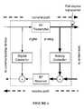
- FIG. 1is a schematic representation of a full-duplex transceiver
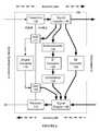
- FIG. 2is a schematic representation of a system of a preferred embodiment
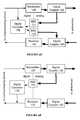
- FIG. 3is a schematic representation of a receiver of a system of a preferred embodiment
- FIG. 4is a schematic representation of a transmitter of a system of a preferred embodiment
- FIGS. 5A and 5Bare schematic representations of signal couplers of a system of a preferred embodiment
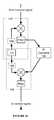
- FIG. 6is a schematic representation of an RF self-interference canceller of a system of a preferred embodiment
- FIG. 7is a schematic representation of an IF self-interference canceller of a system of a preferred embodiment
- FIG. 8is a frequency spectrum view of signal frequency sub-bands
- FIGS. 9A , 9 B, 9 C, 9 D, 9 E, and 9 Fare schematic views of digital canceller coupling of a system of a preferred embodiment
- FIGS. 10A and 10Bare schematic views of digital canceller coupling of a system of a preferred embodiment
- FIG. 11is a schematic view of tuning circuit coupling of a system of a preferred embodiment
- FIG. 12is a schematic view of a system of a preferred embodiment
- FIG. 13is a schematic view of a system of a preferred embodiment
- FIG. 14is a schematic view of a system of a preferred embodiment
- FIG. 15is a schematic view of digital canceller coupling of a system of a preferred embodiment
- FIG. 16is a schematic view of local oscillator sharing
- FIG. 17is a schematic view of a system of a preferred embodiment
- FIG. 18is a chart view of a method of a preferred embodiment
- FIG. 19is a chart view of RF self-interference cancellation signal generation of a method of a preferred embodiment
- FIG. 20is a chart view of ISRF self-interference cancellation signal generation of a method of a preferred embodiment.
- FIG. 21is a chart view of DSRF self-interference cancellation signal generation of a method of a preferred embodiment.
- Wireless communications systemshave revolutionized the way the world communicates, and the rapid growth of communication using such systems has provided increased economic and educational opportunity across all regions and industries.
- the wireless spectrum required for communicationis a finite resource, and the rapid growth in wireless communications has also made the availability of this resource ever scarcer.
- spectral efficiencyhas become increasingly important to wireless communications systems.
- full-duplex wireless communications systemshave substantial value to the wireless communications field, such systems have been known to face challenges due to self-interference; because reception and transmission occur at the same time on the same channel, the received signal at a full-duplex transceiver may include undesired signal components from the signal being transmitted from that transceiver. As a result, full-duplex wireless communications systems often include analog and/or digital self-interference cancellation circuits to reduce self-interference.
- Full-duplex transceiverspreferably sample transmission output as baseband digital signals, intermediate frequency (IF) analog signals, or as radio-frequency (RF) analog signals, but full-duplex transceivers may additionally or alternatively sample transmission output in any suitable manner.
- This sampled transmission outputmay be used by full-duplex transceivers to remove interference from received wireless communications data (e.g., as RF/IF analog signals or baseband digital signals).
- an analog self-interference cancellation systemis paired with a digital self-interference cancellation system. The analog cancellation system removes a first portion of self-interference by summing delayed and scaled versions of the RF transmit signal to create an RF self-interference signal, which is then subtracted from the RF receive signal.
- the analog cancellation systemmay perform similar tasks at an intermediate frequency. After the RF (or IF) receive signal has the RF/IF self-interference signal subtracted, it passes through an analog-to-digital converter of the receiver (and becomes a digital receive signal). After this stage, a digital self-interference cancellation signal (created by transforming a digital transmit signal) is then subtracted from the digital receive signal.
- This architectureis generally effective for reducing interference, but is limited by the dynamic range of the receiver; digital self-interference cancellation may not be fully effective in such an architecture unless a suitably large amount of self-interference is first removed by analog cancellation. Further, such an architecture may require the use of high dynamic range receivers, which may be prohibitively expensive. This inflexibility may limit the usefulness of a full-duplex transceiver.
- the systems and methods described hereinincrease the performance of full-duplex transceivers as shown in FIG. 1 (and other applicable systems) by mitigating receiver dynamic range issues, thus allowing for increased effectiveness in self-interference cancellation.
- Other applicable systemsinclude active sensing systems (e.g., RADAR), wired communications systems, wireless communications systems, and/or any other suitable system, including communications systems where transmit and receive bands are close in frequency, but not overlapping.
- a system 100 for hybrid self-interference cancellationincludes a receiver 110 , a transmitter 120 , a signal coupler 130 , a downconverter 140 , an upconverter 145 , a radio-frequency (RF) self-interference canceller 150 , an intermediate-frequency (IF) self-interference canceller 160 , and a digital self-interference canceller 170 .
- the system 100may additionally include a tuning circuit 180 and/or a delayer 190 .
- the system 100functions to increase the performance of full-duplex transceivers (or other applicable systems) by performing hybrid self-interference cancellation.
- the system 100preferably performs hybrid self-interference cancellation by performing RF, IF, and digital self-interference cancellation based on a single sampled analog transmit signal, but may additionally or alternatively perform hybrid self-interference cancellation by performing RF, IF, and digital self-interference cancellation based on any number of sampled analog and/or digital transmit signals.
- the system 100preferably performs RF, IF, and digital self-interference cancellation simultaneously and in parallel, but may additionally or alternatively perform RF, IF, and/or digital self-interference cancellation at any suitable times and in any order.
- the system 100is preferably implemented using both digital and analog circuitry.
- Digital circuitryis preferably implemented using a general-purpose processor, a digital signal processor, an application specific integrated circuit (ASIC), a field programmable gate array (FPGA) and/or any suitable processor(s) or circuit(s).
- Analog circuitryis preferably implemented using analog integrated circuits (ICs) but may additionally or alternatively be implemented using discrete components (e.g., capacitors, resistors, transistors), wires, transmission lines, waveguides, digital components, mixed-signal components, or any other suitable components.
- the system 100preferably includes memory to store configuration data, but may additionally or alternatively be configured using externally stored configuration data or in any suitable manner.
- the receiver 110functions to receive analog receive signals transmitted over a communications link (e.g., a wireless channel, a coaxial cable).
- a communications linke.g., a wireless channel, a coaxial cable.
- the receiver 110preferably converts analog receive signals into digital receive signals for processing by a communications system, but may additionally or alternatively not convert analog receive signals (passing them through directly without conversion).
- the receiver 110is preferably a radio-frequency (RF) receiver, but may additionally or alternatively be any suitable receiver.
- RFradio-frequency
- the receiver 110is preferably coupled to the communications link by a duplexer-coupled RF antenna, but may additionally or alternatively be coupled to the communications link in any suitable manner. Some examples of alternative couplings include coupling via one or more dedicated receive antennas. In another alternative coupling, the receiver 110 may be coupled to the communications link by a circulator-coupled RF antenna.
- the receiver 110preferably includes an analog-to-digital converter (ADC) in and a frequency downconverter 112 , as shown in FIG. 3 .
- the receiver 110may additionally include a low-noise amplifier 113 .
- the receiver 110may additionally or alternatively include amplifiers, filters, signal processors and/or any other suitable components.
- the receiver 110includes only analog processing circuitry (e.g., amplifiers, fillers, attenuators, delayers). The receiver may function to scale, shift, and/or otherwise modify the receive signal.
- the downconverter 112functions to downconvert the analog receive signal from RF (or any other suitable frequency) to a baseband analog receive signal
- the analog-to-digital converter (ADC) 111functions to convert the baseband analog receive signal to a digital receive signal.
- the ADC 111may be any suitable analog-to-digital converter; e.g., a direct-conversion ADC, a flash ADC, a successive-approximation ADC, a ramp-compare ADC, a Wilkinson ADC, an integrating ADC, a delta-encoded ADC, a time-interleaved ADC, or any other suitable type of ADC.
- a direct-conversion ADCe.g., a flash ADC, a successive-approximation ADC, a ramp-compare ADC, a Wilkinson ADC, an integrating ADC, a delta-encoded ADC, a time-interleaved ADC, or any other suitable type of ADC.
- the frequency downconverter 112functions to downconvert the carrier frequency of the analog receive signal to baseband, preparing it for conversion to a digital receive signal.
- the downconverter 112preferably accomplishes signal downconversion using heterodyning methods, but may additionally or alternatively use any suitable upconversion methods.
- the downconverter 112preferably includes a local oscillator (LO), a mixer, and a baseband filter.
- the local oscillatorfunctions to provide a frequency shift signal to the mixer; the mixer combines the frequency shift signal and the analog receive signal to create (usually two) frequency shifted signals, one of which is the baseband signal, and the baseband filter rejects signals other than the baseband analog receive signal.
- the local oscillatoris preferably a digital crystal variable-frequency oscillator (VFO) but may additionally or alternatively be an analog VFO or any other suitable type of oscillator.
- VFOdigital crystal variable-frequency oscillator
- the local oscillatorpreferably has a tunable oscillation frequency but may additionally or alternatively have a static oscillation frequency.
- the mixeris preferably an active mixer, but may additionally or alternatively be a passive mixer.
- the mixermay comprise discrete components, analog ICs, digital ICs, and/or any other suitable components.
- the mixerpreferably functions to combine two or more electrical input signals into one or more composite outputs, where each output includes some characteristics of at least two input signals.
- the baseband filteris preferably a lowpass filter with a tunable low-pass frequency. Additionally or alternatively, the baseband filter may be a lowpass filter with a set low-pass frequency, or any other suitable type of filter.
- the baseband filteris preferably a passive filter, but may additionally or alternatively be an active filter.
- the baseband filteris preferably implemented with analog circuit components, but may additionally or alternatively be digitally implemented.
- the transmitter 120functions to transmit signals of the communications system over a communications link to a second communications system.
- the transmitter 120preferably converts digital transmit signals into analog transmit signals.
- the transmitter 120is preferably a radio-frequency (RF) transmitter, but may additionally or alternatively be any suitable transmitter.
- RFradio-frequency
- the transmitter 120is preferably coupled to the communications link by a duplexer-coupled RF antenna, but may additionally or alternatively be coupled to the communications link in any suitable manner. Some examples of alternative couplings include coupling via one or more dedicated transmit antennas. In another alternative coupling, the transmitter 120 may be coupled to the communications link by a duplexer-coupled RF antenna.
- the transmitter 120preferably includes a digital-to-analog converter (DAC) 121 and a frequency upconverter 122 , as shown in FIG. 4 .
- the transmitter 120may additionally include a power amplifier 123 .
- the transmitter 120may additionally or alternatively include amplifiers, filters, signal processors and/or any other suitable components.
- the transmitter 120may function to scale, shift, and/or otherwise modify the transmit signal.
- the digital-to-analog converter (DAC) 121functions to convert the digital transmit signal to a baseband analog transmit signal
- the upconverter 122functions to upconvert the baseband analog transmit signal from baseband to RF (or any other intended transmission frequency).
- the DAC 121may be any suitable digital-to-analog converter; e.g., a pulse-width modulator, an oversampling DAC, a binary-weighted DAC, an R-2R ladder DAC, a cyclic DAC, a thermometer-coded DAC, or a hybrid DAC.
- a pulse-width modulatore.g., a pulse-width modulator, an oversampling DAC, a binary-weighted DAC, an R-2R ladder DAC, a cyclic DAC, a thermometer-coded DAC, or a hybrid DAC.
- the frequency upconverter 122functions to upconvert the carrier frequency of the baseband analog transmit signal to a radio frequency, preparing it for transmission over the communications link.
- the upconverter 122preferably accomplishes signal upconversion using heterodyning methods, but may additionally or alternatively use any suitable upconversion methods.
- the upconverter 122preferably includes a local oscillator (LO), a mixer, and an RF filter.
- the local oscillatorfunctions to provide a frequency shift signal to the mixer; the mixer combines the frequency shift signal and the baseband analog transmit signal to create (usually two) frequency shifted signals, one of which is the RF analog transmit signal, and the RF filter rejects signals other than the RF analog transmit signal.
- the local oscillatoris preferably a digital crystal variable-frequency oscillator (VFO) but may additionally or alternatively be an analog VFO or any other suitable type of oscillator.
- VFOdigital crystal variable-frequency oscillator
- the local oscillatorpreferably has a tunable oscillation frequency but may additionally or alternatively have a static oscillation frequency.
- the mixeris preferably an active mixer, but may additionally or alternatively be a passive mixer.
- the mixermay comprise discrete components, analog ICs, digital ICs, and/or any other suitable components.
- the mixerpreferably functions to combine two or more electrical input signals into one or more composite outputs, where each output includes some characteristics of at least two input signals.
- the RF filteris preferably a bandpass filter centered around a tunable radio frequency. Additionally or alternatively, the RF filter may be a bandpass filter centered around a set radio frequency, or any other suitable type of filter.
- the RF filteris preferably a passive filter, but may additionally or alternatively be an active filter.
- the RF filteris preferably implemented with analog circuit components, but may additionally or alternatively be digitally implemented.
- the signal coupler 130functions to allow signals to be split and/or joined.
- the signal coupler 130may be used to provide a sample of the analog transmit signal for the RF canceller 150 , the IF canceller 160 , and/or the digital canceller 170 , as shown in FIG. 5A ; that is, the signal coupler 130 may serve as a transmit coupler.
- the signal coupler 130may also be used to combine one or more analog self-interference cancellation signals (from RF/IF/digital cancellers) with the analog receive signal, as shown in FIG. 5B ; that is, the signal coupler 130 may serve as a receive coupler. Additionally or alternatively, the signal coupler 130 may be used for any other purpose.
- the signal coupler 130is preferably directly coupled to the transmitter 120 , but may additionally or alternatively be coupled indirectly to the transmitter 120 and/or be coupled to another suitable RF transmission source.
- the signal coupler 130preferably has at least two outputs; one coupled to antenna(e) (directly or indirectly) and another coupled to one or more of the RF canceller 150 , the IF canceller 160 , and the digital canceller 170 .
- the signal coupler 130preferably routes the majority of input power to the antenna(e) output port, but may additionally or alternatively route power in any suitable manner (e.g., routing the majority of power to other output ports).
- the signal coupler 130may have any number of input and output ports, including bidirectional input/output ports.
- the receive coupler 130is preferably directly to the receiver no, but may additionally or alternatively be coupled indirectly to the receiver no and/or be coupled to another suitable RF receiver.
- the signal coupler 130preferably has at least two inputs, one coupled to antenna(e) of the full-duplex radio (directly or indirectly) and another coupled to one or more of the RF canceller 150 , the IF canceller 160 , and the digital canceller 170 .
- the signal coupler 130preferably couples the majority of power from both input ports to the receiver output port; this coupling preferably results in the receiver output port outputting a sum of one or more self-interference cancellation signals (generated by 150 / 160 / 170 ) and the RF receive signal (received at the antenna(e)). Additionally or alternatively, the signal coupler 130 may couple or route power in any suitable manner.
- the signal coupler 130may have any number of input and output ports, including bidirectional input/output ports.
- the signal coupler 130is preferably a short section directional transmission line coupler, but may additionally or alternatively be any power divider, power combiner, directional coupler, or other type of signal splitter.
- the signal coupler 130is preferably a passive coupler, but may additionally or alternatively be an active coupler (for instance, including power amplifiers).
- the signal coupler 130may comprise a coupled transmission line coupler, a branch-line coupler, a Lange coupler, a Wilkinson power divider, a hybrid coupler, a hybrid ring coupler, a multiple output divider, a waveguide directional coupler, a waveguide power coupler, a hybrid transformer coupler, a cross-connected transformer coupler, a resistive tee, and/or a resistive bridge hybrid coupler.
- the output ports of the signal coupler 130are preferably phase-shifted by ninety degrees, but may additionally or alternatively be in phase or phase shifted by a different amount.
- the system 100preferably includes two signal couplers 130 (a transmit and a receive coupler); these signal couplers 130 preferably connect to a single antenna through a duplexer or circulator, but may additionally or alternatively connect to multiple antennae.
- the transmit coupler and receive couplerconnect to two separate antennae (e.g., a transmit antenna and a receive antenna); in another example, the transmit coupler and receive coupler both connect to the same two antennae.
- the transmit coupler and receive couplermay additionally or alternatively connect to any suitable RF transmit and RF receive sources (e.g., an RF signal transmitted solely over coaxial cable). There may additionally or alternatively be filters, power amplifiers, and/or any other RF signal modifying components between the couplers 130 and antennae.
- the downcoverter 140is preferably communicatively coupled to the RF transmit signal by a signal coupler 130 , and the IF canceller 160 , and preferably receives RF transmit signals from the signal coupler 130 , downconverts the signal to an intermediate frequency, and passes the resulting IF transmit signal to the IF canceller 160 .
- the downconverter 140is preferably substantially similar to the downconverter 112 (although details such as LO frequency and filter configuration may differ between the two), but may additionally or alternatively be any suitable frequency downconverter.
- the upconverter 145functions to upconvert the carrier frequency of the IF self-interference signal (received from the IF canceller 160 ) to a radio frequency, preparing it for combination with the RF receive signal at a signal coupler 130 .
- the upconverter 145is preferably communicatively coupled to the signal coupler 130 and the IF canceller 160 , and preferably receives IF self-interference cancellation signals from the IF canceller 160 , upconverts the signal to a radio frequency, and passes the resulting RF self-interference cancellation signal to the signal coupler 130 .
- the RF self-interference canceller 150functions to produce an RF self-interference cancellation signal from the analog transmit signal that can be combined with the analog receive signal to reduce self-interference present in the analog receive signal.
- the RF self-interference canceller 150is preferably designed to operate at a single RF frequency band, but may additionally or alternatively be designed to operate at multiple RF frequency bands. Designing the RF self-interference canceller 150 to operate at a single RF frequency band may reduce design compromises that may be made when designing for multiple frequency bands.
- the RF self-interference canceller 150is preferably implemented as an analog circuit that transforms an RF transmit signal into an RF self-interference cancellation signal by combining a set of filtered, scaled, and/or delayed versions of the RF transmit signal, but may additionally or alternatively be implemented as any suitable circuit.
- the RF self-interference canceller 150may perform a transformation involving only a single version or copy of the RF transmit signal.
- the transformed signal(the RF self-interference cancellation signal) preferably represents at least a part of the self-interference component received at the receiver 110 .
- the RF self-interference canceller 150is preferably adaptable to changing self-interference parameters in addition to changes in the analog transmit signal; for example, RF transceiver temperature, ambient temperature, antenna configuration, humidity, and RF transmitter power. Adaptation of the RF self-interference canceller 150 is preferably performed by the tuning circuit 180 , but may additionally or alternatively be performed by a control circuit or other control mechanism included in the canceller 150 or any other suitable controller.
- the RF self-interference canceller 150includes a signal divider 151 , delayers 152 , scalers 153 , and a signal combiner 154 , as shown in FIG. 6 .
- the RF self-interference cancellermay additionally include tunable filters substantially similar to those shown in FIG. 7 (tunable filters 162 ).
- the RF self-interference canceller 150splits the RF transmit signal into multiple signal paths using the signal divider 151 and transforms each signal path individually before recombining them at the signal combiner 154 .
- the RF self-interference canceller 150preferably transforms each signal path by delaying (with the delayer 152 ) and scaling (with the scaler 153 ) signal components on each signal path.
- the divider 151 outputis coupled to the scaler 153 inputs and the scaler 153 outputs are coupled to the delayer 152 inputs.
- the divider 151 outputis coupled to the delayer 152 inputs, and the delayer 152 outputs are coupled to the scaler 153 inputs.
- the components of the RF self-interference controller 150may be coupled in any manner that enables RF self-interference cancellation for the system 100 .
- each signal pathincludes both a scaler 153 and a delayer 152 ; in an alternate implementation, signal paths may include only one of a scaler 153 and a delayer 152 or neither.
- the signal divider 151functions to split the RF transmit signal into multiple transmit signal paths.
- the signal divider 151preferably splits the RF transmit signal into multiple RF transmit signals having substantially the same waveform as the input RF transmit signal and equal power; the signal divider 151 may additionally or alternatively split the RF transmit signal into multiple RF transmit signals having different power levels and/or containing different waveforms than the input RF transmit signal.
- the signal divider 151is preferably a transmission line power divider, but may additionally or alternatively be any suitable power divider, splitter, or coupler.
- the signal divider 151may additionally contain any suitable electronics for pre-processing the RF transmit signal; for example, the signal divider 151 may contain an amplifier to increase the power contained in one or more of the output RF transmit signals.
- the delayers 152function to delay RF transmit signal components.
- the delay introduced by each delayer 152(also referred to as a delayer delay) is preferably fixed (i.e., the delayer 152 is a fixed delayer), but delayers 152 may additionally or alternatively introduce variable delays.
- the delayer 152is preferably implemented as an analog delay circuit (e.g., a bucket-brigade device, a long transmission line, a series of RC networks) but may additionally or alternatively be implemented in any other suitable manner. If the delayer 152 is a variable delayer, the delay introduced is preferably set by the tuning circuit 180 , but may additionally or alternatively be set in any suitable manner.
- the scalers 153function to scale RF transmit signal components; specifically, the scalers 153 effectively multiply the RF transmit signal components by a scale factor. For example, an attenuation of 34% might be represented as a scale factor of 0.66; a gain of 20% might be represented as a scale factor of 1.20; and an attenuation of 10% and a phase inversion might be represented as a scale factor of ⁇ 0.90.
- the scalers 153provide the weighting for the combination of RF self-interference components at the signal combiner 154 (e.g., a signal with scale factor 2 is weighted twice as heavily as one with a scale factor of 1).
- the scalers 153may include attenuators, amplifiers, phase inverters, and/or any other suitable components for scaling RF transmit signal components.
- Attenuatorsmay be resistive attenuators (T pad, Pi pad), amplifiers with less than unity gain, or any other suitable type of attenuator.
- Amplifiersmay be transistor amplifiers, vacuum tube amplifiers, op-amps, or any other suitable type of amplifier.
- Phase invertersmay be any phase inversion devices, including NPN/PNP phase inversion circuits and/or inverting amplifiers.
- the scalers 153preferably are capable of attenuation, gain, and phase inversion, but may alternatively be capable only of a subset of said capabilities.
- Each scaler 153preferably includes all three capabilities in a single device (e.g., an amplifier with tunable gain and two outputs, one inverted and one non-inverted) but may additionally or alternatively separate capabilities into different sections (e.g., an amplifier with tunable gain but 110 inversion capability, along with a separate phase inversion circuit).
- the scalers 153are preferably controlled by the tuning circuit 180 , but may additionally or alternatively be controlled in any suitable manner.
- the tuning circuit 180preferably controls scalers 153 by dynamically setting scale factors for each scaler 153 , but may additionally or alternatively control scalers 153 in any suitable manner.
- RF transmit signal componentsare transformed into RF self-interference cancellation signal components, which may be combined to form an RF self-interference cancellation signal.
- the signal combiner 154functions to combine the RF self-interference cancellation signal components into an RF self-interference cancellation signal; the RF self-interference cancellation signal may then be combined with an RF receive signal to remove self-interference.
- the signal combiner 154preferable combines RF self-interference cancellation signal components (resulting from multiple signal paths) and outputs the resulting RF self-interference cancellation signal.
- the signal combiner 154is preferably a transmission line coupler, but may additionally or alternatively be any suitable type of coupler (described in the signal coupler 130 sections).
- the signal combiner 154may additionally contain any suitable electronics for post-processing the RF self-interference cancellation signal before outputting it; for example, the signal combiner 154 may contain an amplifier to increase the power of the RF self-interference cancellation signal.
- the IF analog self-interference canceller 160functions to produce an IF self-interference signal from the IF transmit signal (i.e., the downconverted RF transmit signal) that, after upconversion, can be combined with the RF receive signal to reduce self-interference present in the RF receive signal.
- the IF analog self-interference canceller 160is preferably designed to operate at a single IF frequency band, but may additionally or alternatively be designed to operate at multiple IF frequency bands. Designing the IF analog self-interference canceller 160 to operate at a single IF frequency band may reduce design compromises that may be made when designing for multiple frequency bands.
- the downconverter 140 and upconverter 145may enable signals of multiple RF frequency bands to be converted to the same IF frequency band; an IF analog self-interference canceller 160 operating at a single IF band may still perform self-interference cancellation for multiple RF frequency bands.
- the IF analog self-interference canceller 160preferably is designed to operate at an intermediate frequency that decreases the component and/or design complexity of the IF analog self-interference canceller 160 required to reach a particular quality threshold. For instance, if it is desired to use a PCB having a certain minimum distance between traces for the IF analog self-interference canceller 160 , it may be desired to choose an intermediate frequency where the capacitance between traces is not a substantial effect on circuit performance. Additionally or alternatively, the IF analog self-interference canceller 160 may operate at any suitable frequency.
- the IF analog self-interference canceller 160is preferably implemented as an analog circuit that transforms an IF transmit signal into an IF self-interference signal by combining a set of filtered, scaled, and/or delayed versions of the IF transmit signal, but may additionally or alternatively be implemented as any suitable circuit.
- the IF analog self-interference canceller 160may perform a transformation involving only a single version or copy of the IF transmit signal.
- the transformed signal(the IF self-interference signal) preferably represents at least a part of the self-interference component received at the receiver 110 .
- the IF analog self-interference canceller 160is preferably adaptable to changing self-interference parameters in addition to changes in the IF transmit signal; for example, RF transceiver temperature, ambient temperature, antenna configuration, humidity, and RF transmitter power. Adaptation of the IF analog self-interference canceller 160 is preferably performed by the tuning circuit 180 , but may additionally or alternatively be performed by a control circuit or other control mechanism included in the canceller 160 or any other suitable controller.
- the IF analog self-interference canceller 160includes a signal divider 161 , tunable filters 162 , scalers 163 , delayers 164 , and a signal combiner 165 , as shown in FIG. 7 .
- the IF analog self-interference canceller 160splits the IF transmit signal into sub-bands using the tunable filters 162 , as shown in FIG. 8 , and transforms each of these sub-bands individually before recombining them at the signal combiner 166 .
- the frequency sub-bandsmay overlap in frequency; there may additionally or alternatively be multiple filters 162 corresponding to the same frequency sub-band. Additionally or alternatively, some tunable filters 162 may pass the entire IF band.
- the IF analog self-interference canceller 160preferably transforms each sub-band by scaling (with the scaler 163 ) and delaying (with the delayer 164 ) signal components of each sub-band.
- the tunable filter 162 outputis coupled to the scaler 163 input and the scaler 163 output is coupled to the delayer 164 input.
- the tunable filter 162 outputis coupled to the delayer 164 input, and the delayer 164 output is coupled to the scaler 163 input.
- the components of the IF analog self-interference controller 160may be coupled in any manner that enables analog self-interference cancellation for the system 100 .
- each signal path(i.e., each path associated with a different tunable filter 162 ) includes both a scaler 163 and a delayer 164 ; in an alternate implementation, signal paths may include only one of a scaler 163 and a delayer 164 or neither.
- Separating the IF transmit signal into sub-bandsenables the IF analog self-interference canceller 160 to generate an effective self-interference signal even when self-interference is highly variable with frequency; for instance, in situations where the full-duplex radio has an antenna configuration not optimized for its RF frequency, where the full-duplex radio is placed in a very strong multipath environment, and/or where the receiver 110 exhibits a substantially frequency-dependent response to RF signal input.
- the signal divider 161functions to split the IF transmit signal into multiple IF transmit signal paths, each directed to a tunable filter 162 .
- the signal divider 161is preferably substantially similar to the signal divider 151 , but may additionally or alternatively be any suitable signal divider.
- Each tunable filter 162functions to isolate IF transmit signal components contained within a frequency band (typically, but not always, a sub-band of the IF transmit signal band) so that the component of self-interference resulting from the part of the IF transmit signal in that frequency band may be generated independently of the components of self-interference resulting from other parts of the IF transmit signal.
- a frequency bandtypically, but not always, a sub-band of the IF transmit signal band
- isolating IF transmit signal components by frequency sub-bandallows for transformations to be performed on each signal component individually, increasing self-interference cancellation performance in situations where self-interference is substantially frequency dependent.
- the tunable filters 162are preferably bandpass filters centered around a tunable intermediate frequency. Additionally or alternatively, the tunable filters 162 may be bandpass filters centered around set radio frequencies, or any other suitable type of filter.
- the tunable filters 162are preferably passive filters, but may additionally or alternatively be active filters.
- the tunable filters 162are preferably implemented with analog circuit components, but may additionally or alternatively be digitally implemented.
- the center frequency of each tunable filter 162is preferably controlled by the tuning circuit 180 , but may additionally or alternatively be controlled by any suitable system (including manually controlled, e.g. as in a mechanically tuned capacitor).
- Each tunable filter 162preferably has a set quality (Q) factor, but may additionally or alternatively have a variable Q factor.
- the tunable filters 162may have different Q factors; for example, some of the tunable filters 162 may be high-Q, some may be low-Q, and some may be no-Q (flat response).
- the scalers 163function to scale IF transmit signal components; specifically, the scalers 153 effectively multiply the IF transmit signal components by a scale factor.
- the scalers 163are preferably substantially similar to the scalers 153 , but may additionally or alternatively be any suitable scalers.
- the delayers 164function to delay IF transmit signal components, preferably to match corresponding delays in received self-interference.
- the delayers 154are preferably substantially similar to the delayers 152 , but may additionally or alternatively be any suitable delayers.
- IF transmit signal componentsare transformed into IF self-interference signal components, which may be combined to form an IF self-interference signal.
- the signal combiner 165functions to combine the IF self-interference signal components into an IF self-interference signal; the IF self-interference signal may then be upconverted into an RF self-interference signal and combined with an RF receive signal to remove self-interference.
- the signal combiner 165is preferably substantially similar to the signal combiner 154 , but may additionally or alternatively be any suitable signal combiner.
- the digital self-interference canceller 170functions to produce a digital self-interference cancellation signal from a digital transmit signal.
- the digital self-interference cancellation signalis preferably converted to an analog self-interference cancellation signal (by the DAC 172 ) and combined with the IF and RF self-interference cancellation signals to further reduce self-interference present in the RF receive signal at the receiver 110 . Additionally or alternatively, the digital self-interference cancellation signal may be combined with a digital receive signal.
- the digital self-interference canceller 170preferably samples the RF transmit signal of the transmitter 120 using the ADC 171 (additionally or alternatively, the canceller 170 may sample the digital transmit signal or any other suitable transmit signal) and transforms the sampled and converted RF transmit signal to a digital self-interference signal based on a digital transform configuration.
- the digital transform configurationpreferably includes settings that dictate how the digital self-interference canceller 170 transforms the digital transmit signal to a digital self-interference signal (e.g. coefficients of a generalized memory polynomial used to transform the transmit signal to a self-interference signal).
- the digital self-interference canceller 170may be implemented using a general-purpose processor, a digital signal processor, an application specific integrated circuit (ASIC), a field programmable gate array (FPGA) and/or any suitable processor(s) or circuit(s).
- the digital self-interference canceller 170preferably includes memory to store configuration data, but may additionally or alternatively be configured using externally stored configuration data or in any suitable manner.
- the digital self-interference canceller 170is substantially similar to the digital self-interference canceller of U.S. patent application Ser. No. 14/456,320, filed 11 Aug. 2014, which is incorporated in its entirety by this reference.
- the ADC 171functions to convert the RF transmit signal to from an analog signal to a digital signal; this signal is hereafter referred to as a converted RF transmit signal.
- the ADCis preferably substantially similar to the ADC 111 , but may additionally or alternatively be any suitable ADC.
- the DAC 172functions to convert the digital self-interference cancellation signal from a digital signal to an analog signal; this signal is hereafter referred to as a converted digital self-interference cancellation signal.
- the DAC 172is preferably substantially similar to the DAC 121 , but may additionally or alternatively be any suitable DAC.
- the digital self-interference canceller 170may couple to transmit and receive signals in a number of ways. For example, as shown in FIG. 9A , the digital self-interference canceller 170 may use a converted RF transmit signal as input as well as provide a converted digital self-interference cancellation signal as output. As another example, the digital self-interference canceller 170 may use the digital transmit signal as input as a well as provide a digital self-interference cancellation signal as output (directly to the digital receive signal), as shown in FIG. 9B . The digital self-interference canceller may additionally or alternatively couple to transmit signals in any combination of digital and analog receive signals. Additional examples are as shown in FIGS. 9C , 9 D, 9 E, and 9 F.
- the digital self-interference canceller 170may additionally or alternatively couple to IF transmit signals and/or IF self-interference cancellation signals, as shown in FIGS. 10A and 10B .
- the tuning circuit 180functions to control the configuration parameters of the RF canceller 150 and/or the IF canceller 160 .
- the tuning circuit 180may additionally or alternatively provide input to or control configuration parameters of the digital canceller 170 .
- Configuration parametersmay include pre-processing settings (at signal dividers 151 / 161 ), filter center frequency and/or Q factor (at tunable filters 162 ), scale factor (at the scalers 153 / 163 ), delay (at the delayers 152 / 164 ), post-processing settings (at the signal combiner 154 / 165 ) and/or any other suitable configuration parameters.
- the tuning circuit 180preferably controls tunable filter 162 center frequencies, scaler 153 / 163 scale factors (including gain/attenuation/phase inversion), and delayer 154 / 165 delays to create RF and/or IF self-interference cancellation signals that reflect some or all of the self-interference contained within received signals.
- the tuning circuit 180preferably sets the configuration state of the RF canceller 150 and/or the IF canceller 160 (where the state includes settings for each variable setting controlled by the tuning circuit 180 ) based upon the received RF/IF transmit signals, but may additionally or alternatively set the configuration state based on any other suitable input.
- Suitable inputmay include signal data (e.g. IF transmit signal, digital transmit signal, RF receive signal), full-duplex radio settings (e.g. RF transmitter power, antenna position), full-duplex radio characteristics (e.g. receiver operating characteristics, transmitter operating characteristics), environmental data (e.g., transceiver temperature, ambient temperature, ambient humidity), and/or any other input relating to self-interference present in the receive signal.
- the tuning circuit 180preferably sets configuration states based on an algorithm responsive to input. This may include a state-choosing algorithm that selects from a set of pre-chosen states based on some input parameter set, a dynamic algorithm that generates states based on the input parameter set (as opposed to choosing from a limited state set), or any other suitable algorithm. Additionally or alternatively, the tuning circuit 180 may set configuration states in any suitable manner.
- the tuning circuit 180may adapt configuration states and/or configuration state generating/choosing algorithms using analytical methods, online gradient-descent methods (e.g., LMS, RLMS), and/or any other suitable methods.
- the tuning circuit 180may additionally or alternatively adapt configuration states and/or configuration state generating/choosing algorithms based on test input scenarios (e.g. scenarios when the signal received by the receiver 110 is known), scenarios where there is no input (e.g. the only signal received at the receiver 110 is the signal transmitted by the transmitter 120 , or scenarios where the received signal is unknown. In cases where the received signal is an unknown signal, the tuning circuit 180 may perform adaptation based on historical received data (e.g. what the signal looked like ten seconds in the past) or any other suitable information.
- the tuning circuit 180may additionally or alternatively perform adaptation based on the content of the RF or IF transmit signals; for instance, if the RF transmit signal is modulated in a particular way, the tuning circuit may perform adaptation such that when the RF self-interference signal is combined with the RF receive signal the detected modulation (as an indicator of self-interference) is reduced.
- the tuning circuit 180is preferably implemented as a programmable digital circuit, but may additionally or alternatively be implemented in any suitable digital or analog circuit, including implementation as software in a general purpose computing device.
- the delayer 190functions to cause signals entering the input port to experience a delay before exiting the output port.
- the delayis preferably a variable delay, but may additionally or alternatively be a set delay.
- the variable delayis preferably set by the tuning circuit 180 , but may additionally or alternatively be set in any suitable manner (e.g., manually controlled switches set by hand, electronic switches controlled by software, etc.).
- the delayer 190is preferably used to adjust for relative delays between self-interference cancellation components; for example, if the output of the IF canceller 160 lags 10 ms behind the output of the RF canceller 150 , the output of the RF canceller 150 may be passed through a delayer with a 10 ms delay to temporally align the two output signals.
- Delayers 190are preferably analog delay circuits, but may additionally or alternatively be digital delay circuits or any suitable delayer.
- delayers 190are the delay matchers of U.S. patent application Ser. No. 14/484,094, which is incorporated in its entirety by this reference.
- the three cancellers ( 150 , 160 , 170 )may be coupled to transmit and receive signals in a variety of ways.
- the input of the digital canceller 170(through the ADC 171 ) may be coupled to the downconverted IF transmit signal and the output of the digital canceller (through the DAC 172 ) may be coupled to the IF self-interference cancellation signal (so that the upconverted self-interference cancellation signal is a combination of both the original IF self-interference cancellation signal and the output of the digital canceller 170 ).
- the digital self-interference cancellation signalis converted to a digitally-sourced IF self-interference cancellation signal and combined with the IF self-interference cancellation signal to form a hybrid self-interference cancellation signal (this term may refer to any combination of self-interference cancellation signal types).
- the digital canceller 170may be coupled to the RF transmit and receive paths, but using a separate signal coupler 130 from the IF and RF cancellers 160 and 150 .
- the system 100may include IF and RF cancellers 160 and 150 without a digital canceller 170 .
- the cancellers 150 / 160 / 170are preferably coupled to signal couplers 130 located after transmitter 120 outputs and before receiver 110 inputs
- the cancellers 150 / 160 / 170may additionally or alternatively be coupled to intermediate outputs and/or inputs (e.g., an output before the transmitter 120 output or an input after the receiver 110 input).
- the pre-amplifier (PA 123 ) output of the transmitter 120serves as the input to the ADC 171
- the output of the DAC 172is routed to the post-amplifier (LNA 113 ) input. While this example shows coupling of the digital canceller 170 to intermediate inputs and outputs any canceller ( 150 , 160 , 170 ) may be coupled to intermediate outputs and/or inputs in similar manner.
- local oscillatorsmay be shared between components of the system 100 .
- the downconverter 140 and upconverter 145may share a local oscillator as shown in FIG. 16 .
- the downconverter 112 and downconverter 140may share a local oscillator. This can serve to reduce phase noise errors.
- Local oscillatorsmay be shared between any components of the system 100 .
- delayers 190may additionally be coupled to the system 100 in a variety of ways.
- delayers 190may be inserted between signal couplers 130 coupled to digital canceller 170 and IF/RF canceller 160 / 150 inputs respectively, as shown in FIG. 17 .
- Delayers 190may also be inserted between signal couplers 130 coupled to digital canceller 170 and IF/RF canceller 160 / 150 outputs respectively, also as shown in FIG. 17 .
- Delayers 190may be located between any components of the system 100 (including subcomponents).
- a delayer 190may be placed between a local oscillator and a mixer, as shown in FIG. 16 . In this case, the delayer 190 can be used to achieve better phase noise cancellation.
- a method 200 for hybrid self-interference cancellationincludes receiving a radio-frequency (RF) transmit signal S 210 , generating an RF self-interference cancellation signal S 220 , generating an IF-sourced (IS) RF self-interference cancellation signal S 230 , generating a digitally-sourced (DS) RF self-interference cancellation signal S 240 , generating a hybrid self-interference cancellation signal S 250 , and combining the hybrid self-interference cancellation signal with an RF receive signal S 260 .
- RFradio-frequency
- the method 200functions to increase the performance of full-duplex transceivers (or other applicable systems) by performing hybrid self-interference cancellation.
- the method 200preferably performs hybrid self-interference cancellation by performing RF, IF, and digital self-interference cancellation based on a single sampled analog transmit signal, but may additionally or alternatively perform hybrid self-interference cancellation by performing RF, IF, and digital self-interference cancellation based on any number of sampled analog and/or digital transmit signals.
- the method 200preferably performs RF, IF, and digital self-interference cancellation simultaneously and in parallel, but may additionally or alternatively perform RF, IF, and/or digital self-interference cancellation at any suitable times and in any order.
- the method 200is preferably implemented by the system 100 , but may additionally or alternatively be implemented by any suitable system for hybrid self-interference cancellation.
- S 210includes receiving a radio-frequency (RF) transmit signal.
- S 210functions to provide an analog RF signal intended for transmission by a full-duplex wireless communications system so that the signal may be used to remove self-interference at the full-duplex wireless communications system receiver.
- RF transmit signals received in S 210preferably include RF signals originating from an electronic device, destined for an antenna or other communication output of a full-duplex radio (or other full-duplex wireless communications system).
- RF transmit signals received in S 210may additionally or alternatively include RF transmit signals from any other suitable source.
- S 210preferably comprises receiving the RF transmit signal by splitting an RF signal somewhere in the signal path between the RF transmitter and the antenna(e) (or other signal output) and passing the RF transmit signal to an frequency downconverter, but may additionally or alternatively receive the RF transmit signal using any other suitable method.
- Step S 220includes generating an RF self-interference cancellation signal.
- S 220functions to produce an RF self-interference cancellation signal from the RF transmit signal, which can be combined with the RF receive signal to reduce self-interference present in the RF receive signal.
- Generating the RF self-interference cancellation signal S 220preferably occurs in a single RF frequency band, but may additionally or alternatively occur in multiple distinct RF frequency bands.
- S 220preferably includes transforming an RF transmit signal into an RF self-interference cancellation signal by combining a set of filtered, scaled, and/or delayed versions of the RF transmit signal, but may additionally or alternatively include transforming RF transmit signals to RF self-interference cancellation signals in any suitable manner.
- the transformed signal(the RF self-interference cancellation signal) preferably represents at least a part of the self-interference component received at the RF receiver of a full-duplex radio.
- the transformation performed in S 220is preferably adaptable to changing self-interference parameters in addition to changes in the RF transmit signal; for example, RF transceiver temperature, ambient temperature, antenna configuration, humidity, and RF transmitter power.
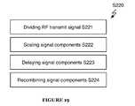
- S 220includes dividing the RF transmit signal into signal components by frequency sub-band S 221 , scaling signal components S 222 , delaying signal components S 223 , and recombining signal components S 224 , as shown in FIG. 19 .
- This implementationseparates the RF transmit signal into frequency sub-bands; enabling the generation of effective self-interference signal even when self-interference is highly variable with frequency; for instance, in situations where the full-duplex radio has an antenna configuration not optimized for its RF frequency, where the full-duplex radio is placed in a very strong multipath environment, and/or where the RF receiver exhibits a substantially frequency-dependent response to RF signal input.
- S 221includes dividing the RF transmit signal into signal components by frequency sub-band.
- Frequency sub-bandsmay overlap in frequency; there may additionally or alternatively be multiple signal components corresponding to the same frequency sub-band. In some cases, frequency sub-bands may encompass the entire RF passband.
- S 221preferably includes splitting the RF transmit signal into multiple RF transmit signal paths and then filtering each signal path.
- the multiple RF transmit signal pathspreferably have substantially the same waveform as the input RF transmit signal and equal power;
- S 221may additionally or alternatively include splitting the RF transmit signal into multiple RF transmit signals having different power levels and/or containing a different waveform than the input RF transmit signal.
- S 221preferably filters each signal path to isolate RF transmit signal components contained within a frequency band (typically, but not always, a sub-band of the RF transmit signal band) so that the component of self-interference resulting from the part of the RF transmit signal in that frequency band may be generated independently of the components of self-interference resulting from other parts of the RF transmit signal.
- a frequency bandtypically, but not always, a sub-band of the RF transmit signal band
- isolating RF transmit signal components by frequency sub-bandallows for transformation to be performed on each signal component individually, increasing self-interference cancellation performance in situations where self-interference is substantially frequency dependent.
- Splitting parametersare preferably controlled dynamically, but may additionally or alternatively be static.
- S 222includes scaling signal components.
- S 222functions to effectively multiply the RF transmit signal components by a scale factor. For example, an attenuation of 34% might be represented as a scale factor of 0.66; a gain of 20% might be represented as a scale factor of 1.20; and an attenuation of 10% and a phase inversion might be represented as a scale factor of ⁇ 0.90.
- S 222also functions to provide weighting for the combination of RF self-interference components during S 224 (e.g., a signal with scale factor 2 is weighted twice as heavily as one with a scale factor of 1).
- Scalingmay include attenuating, amplifying, and/or inverting phase. Scaling parameters are preferably controlled dynamically, but may additionally or alternatively be static.
- S 223includes delaying signal components.
- S 223functions to delay RF transmit signal components, preferably to match corresponding delays in received self-interference.
- the delay introduced by S 223 in each signal componentis preferably variable (and controlled dynamically) but S 223 may additionally or alternatively include introducing set delays.
- RF transmit signal componentsare transformed into RF self-interference cancellation signal components, which may be combined to form an RF self-interference cancellation signal.
- S 224includes recombining signal components.
- S 224functions to combine the RF self-interference signal components into an RF self-interference cancellation signal; the RF self-interference cancellation signal may then be combined with an RF receive signal to remove self-interference.
- S 224preferably includes recombining signal components without performing any additional weighting (beyond that performed by S 222 ) but may additionally or alternatively include any suitable post-processing to prepare the RF self-interference signal for combination with the RF receive signal; for example, amplifying, delaying, or inverting the RF self-interference cancellation signal.
- Step S 230generating an ISRF self-interference cancellation signal, is preferably substantially similar to Step S 220 except that Step S 230 includes additional upconversion and downconversion steps, and self-interference transformation is performed on IF signals instead of RF signals.
- Step S 230preferably includes downconverting the RF transmit signal to an intermediate frequency, generating an IF self-interference cancellation signal, and upconverting the IF self-interference cancellation signal.
- S 230includes downconverting the RF transmit signal to an IF transmit signal S 231 , dividing the IF transmit signal into signal components by frequency sub-band S 232 , scaling signal components S 233 , delaying signal components S 234 , recombining signal components S 235 , and upconverting the IF self-interference cancellation signal to an RF self-interference cancellation signal S 236 , as shown in FIG. 20 .
- This implementationseparates the IF transmit signal into frequency sub-bands; enabling the generation of effective self-interference signal even when self-interference is highly variable with frequency; for instance, in situations where the full-duplex radio has an antenna configuration not optimized for its RF frequency, where the full-duplex radio is placed in a very strong multipath environment, and/or where the RF receiver exhibits a substantially frequency-dependent response to RF signal input.
- Step S 231includes downconverting the RF transmit signal to an intermediate frequency (IF) transmit signal.
- S 231preferably includes downconverting the RF transmit signal using heterodyning methods, but may additionally or alternatively use any suitable downconversion methods.
- S 231may enable RF signals of different carrier frequency to be downconverted to the same IF carrier frequency. Enabling different RF carrier frequencies to be converted to the same IF carrier frequency allows IF analog self-interference generation to occur at a single (IF) frequency independent of RF frequencies.
- S 231may additionally or alternatively include any other suitable processing to prepare the RF transmit signal for transformation (e.g., scaling, shifting, and/or otherwise modifying the RF transmit signal).
- Steps S 232 , S 233 , S 234 , and S 235are preferably substantially similar to Steps S 221 , S 222 , S 223 , and S 234 respectively, except that transformation is performed on IF signals instead of RF signals.
- Step S 236includes upconverting the IF self-interference signal to an RF self-interference signal.
- S 236functions to upconvert the carrier frequency of the IF self-interference cancellation signal (generated in S 235 ) to the RF carrier frequency of the RF receive signal (or any other suitable RF frequency) preparing it for combination with the RF receive signal.
- S 236preferably includes upconverting the IF self-interference signal using heterodyning methods, but may additionally or alternatively use any suitable upconversion methods.
- Step S 236may additionally or alternatively include any other suitable processing to prepare the IF self-interference cancellation for hybrid self-interference signal generation in Step S 250 (e.g., scaling, shifting, and/or otherwise modifying the IF self-interference cancellation signal).
- any other suitable processing to prepare the IF self-interference cancellation for hybrid self-interference signal generation in Step S 250e.g., scaling, shifting, and/or otherwise modifying the IF self-interference cancellation signal.
- Step S 240includes generating a DSRF self-interference cancellation signal.
- S 240functions to produce a digital self-interference cancellation signal from a digitized RF transmit signal, which can then be combined (either with the RF receive signal or the digital receive signal) to reduce self-interference.
- Step S 240preferably includes converting the RF transmit signal to a digitized RF transmit signal S 241 , transforming the digitized RF transmit signal into a digital self-interference signal S 242 , and converting the digital self-interference cancellation signal to a digitally-sourced RF self-interference cancellation signal S 243 , as shown in FIG. 21 .
- Steps S 241 and S 243are optional—in particular, if Step S 241 is not performed, Step S 242 is preferably performed on a digital transmit signal (e.g., digital signal before conversion by a transmitter) instead of on a digitized RF transmit signal.
- Step S 241includes converting the RF transmit signal to a digitized RF transmit signal.
- S 241functions to perform analog-to-digital conversion on the RF transmit signal.
- S 241is preferably performed on the transmit signal after the power amplifier, but may additionally or alternatively be performed on the RF transmit signal at any coupling location or any point in time. In some cases, Step S 241 may be performed on related signals (e.g., an IF transmit signal).
- S 241may additionally or alternatively include any other suitable processing to prepare the RF transmit signal for analog-to-digital conversion (e.g., scaling, shifting, and/or otherwise modifying the RF transmit signal).
- Step S 242includes transforming the digitized RF transmit signal into a digital self-interference cancellation signal.
- S 242functions to produce a digital self-interference signal from the digitized RF transmit signal (or from any digital transmit signal).
- S 242preferably includes transforming the digital transmit signal to a digital self-interference signal based on a digital transform configuration.
- the digital transform configurationpreferably includes settings that dictate how the digital transmit signal is transformed to a digital self-interference cancellation signal (e.g., coefficients of a generalized memory polynomial used to transform the transmit signal to a self-interference signal).
- Step S 243includes converting the digital self-interference cancellation signal to a digitally-sourced RF self-interference cancellation signal.
- S 241functions to perform digital-to-analog conversion on the digital self-interference cancellation signal.
- S 243preferably includes converting the digital self-interference cancellation signal to a DSRF self-interference cancellation signal in a two-step process; first converting the digital self-interference cancellation signal to a baseband self-interference cancellation signal and then converting the baseband self-interference cancellation signal to an RF self-interference cancellation signal. Additionally or alternatively, S 243 may include converting the digital self-interference cancellation signal to a DSRF self-interference cancellation signal using any other suitable process.
- S 243may alternatively include converting the digital self-interference cancellation signal to a digitally-sourced intermediate frequency (DSIF) self-interference cancellation signal.
- S 243may additionally or alternatively include any other suitable processing to prepare the digital self-interference cancellation signal for digital-to-analog conversion (e.g., scaling, shifting, and/or otherwise modifying the digital self-interference cancellation signal).
- Step S 250includes generating a hybrid self-interference cancellation signal.
- Step S 250functions to generate a self-interference cancellation signal from one or more of the RF, ISRF, and DSRF self-interference cancellation signals.
- Step S 250preferably includes combining all three self-interference cancellation signals with the RF receive signal at a signal coupler, but may additionally or alternatively include combining self-interference cancellation signals in any order and in any location.
- Step S 250may include combining RF and ISRF signals at a first signal coupler, but DSRF signals at a second signal coupler (as shown in FIG. 17 ).
- Step S 250may additionally include any suitable signal processing (e.g., weighting signals, phase-shift signals, scaling signals, etc.).
- Step S 260includes combining the hybrid self-interference cancellation signal with an RF receive signal.
- S 260functions to couple the hybrid self-interference cancellation signal generated by the method 200 to the RF receive signal of the full-duplex radio.
- S 260preferably includes coupling the majority of input power to the RF receiver signal; this coupling preferably results in the RF receiver receiving a sum of the self-interference signal (generated in S 250 ) and the RF receive signal (received at the antenna(e)). Additionally or alternatively, S 260 may include coupling or routing power in any suitable manner.
- the methods of the preferred embodiment and variations thereofcan be embodied and/or implemented at least in part as a machine configured to receive a computer-readable medium storing computer-readable instructions.
- the instructionsare preferably executed by computer-executable components preferably integrated with a system for hybrid self-interference cancellation.
- the computer-readable mediumcan be stored on any suitable computer-readable media such as RAMs, ROMs, flash memory, EEPROMs, optical devices (CD or DVD), hard drives, floppy drives, or any suitable device.
- the computer-executable componentis preferably a general or application specific processor, but any suitable dedicated hardware or hardware/firmware combination device can alternatively or additionally execute the instructions.
Landscapes
- Engineering & Computer Science (AREA)
- Signal Processing (AREA)
- Computer Networks & Wireless Communication (AREA)
- Transceivers (AREA)
Abstract
Description
Claims (18)
Priority Applications (4)
| Application Number | Priority Date | Filing Date | Title |
|---|---|---|---|
| US14/569,354US9077421B1 (en) | 2013-12-12 | 2014-12-12 | Systems and methods for hybrid self-interference cancellation |
| US14/728,501US9337885B2 (en) | 2013-12-12 | 2015-06-02 | Systems and methods for hybrid self-interference cancellation |
| US14/812,552US9774405B2 (en) | 2013-12-12 | 2015-07-29 | Systems and methods for frequency-isolated self-interference cancellation |
| US15/686,022US10230422B2 (en) | 2013-12-12 | 2017-08-24 | Systems and methods for modified frequency-isolation self-interference cancellation |
Applications Claiming Priority (2)
| Application Number | Priority Date | Filing Date | Title |
|---|---|---|---|
| US201361915431P | 2013-12-12 | 2013-12-12 | |
| US14/569,354US9077421B1 (en) | 2013-12-12 | 2014-12-12 | Systems and methods for hybrid self-interference cancellation |
Related Child Applications (1)
| Application Number | Title | Priority Date | Filing Date |
|---|---|---|---|
| US14/728,501ContinuationUS9337885B2 (en) | 2013-12-12 | 2015-06-02 | Systems and methods for hybrid self-interference cancellation |
Publications (2)
| Publication Number | Publication Date |
|---|---|
| US20150171903A1 US20150171903A1 (en) | 2015-06-18 |
| US9077421B1true US9077421B1 (en) | 2015-07-07 |
Family
ID=53369755
Family Applications (2)
| Application Number | Title | Priority Date | Filing Date |
|---|---|---|---|
| US14/569,354ActiveUS9077421B1 (en) | 2013-12-12 | 2014-12-12 | Systems and methods for hybrid self-interference cancellation |
| US14/728,501ActiveUS9337885B2 (en) | 2013-12-12 | 2015-06-02 | Systems and methods for hybrid self-interference cancellation |
Family Applications After (1)
| Application Number | Title | Priority Date | Filing Date |
|---|---|---|---|
| US14/728,501ActiveUS9337885B2 (en) | 2013-12-12 | 2015-06-02 | Systems and methods for hybrid self-interference cancellation |
Country Status (2)
| Country | Link |
|---|---|
| US (2) | US9077421B1 (en) |
| WO (1) | WO2015089460A1 (en) |
Cited By (46)
| Publication number | Priority date | Publication date | Assignee | Title |
|---|---|---|---|---|
| US20150222344A1 (en)* | 2014-02-06 | 2015-08-06 | Imec Vzw | Modulation Circuit for a Radio Device and A Method Thereof |
| US20150333847A1 (en)* | 2013-12-12 | 2015-11-19 | Kumu Networks, Inc. | Systems and methods for frequency-isolated self-interference cancellation |
| US9413516B2 (en) | 2013-11-30 | 2016-08-09 | Amir Keyvan Khandani | Wireless full-duplex system and method with self-interference sampling |
| US9479322B2 (en) | 2013-11-30 | 2016-10-25 | Amir Keyvan Khandani | Wireless full-duplex system and method using sideband test signals |
| US9572038B2 (en) | 2012-05-13 | 2017-02-14 | Amir Keyvan Khandani | Full duplex wireless transmission with channel phase-based encryption |
| US9577690B2 (en) | 2007-05-23 | 2017-02-21 | Hypres, Inc. | Wideband digital spectrometer |
| US9634823B1 (en) | 2015-10-13 | 2017-04-25 | Kumu Networks, Inc. | Systems for integrated self-interference cancellation |
| US9667299B2 (en) | 2013-08-09 | 2017-05-30 | Kumu Networks, Inc. | Systems and methods for non-linear digital self-interference cancellation |
| US9673854B2 (en) | 2015-01-29 | 2017-06-06 | Kumu Networks, Inc. | Method for pilot signal based self-inteference cancellation tuning |
| US9698860B2 (en) | 2013-08-09 | 2017-07-04 | Kumu Networks, Inc. | Systems and methods for self-interference canceller tuning |
| US9712313B2 (en) | 2014-11-03 | 2017-07-18 | Kumu Networks, Inc. | Systems for multi-peak-filter-based analog self-interference cancellation |
| US9712312B2 (en) | 2014-03-26 | 2017-07-18 | Kumu Networks, Inc. | Systems and methods for near band interference cancellation |
| US9742593B2 (en) | 2015-12-16 | 2017-08-22 | Kumu Networks, Inc. | Systems and methods for adaptively-tuned digital self-interference cancellation |
| US9755692B2 (en) | 2013-08-14 | 2017-09-05 | Kumu Networks, Inc. | Systems and methods for phase noise mitigation |
| US9800275B2 (en) | 2015-12-16 | 2017-10-24 | Kumu Networks, Inc. | Systems and methods for out-of band-interference mitigation |
| US9819325B2 (en) | 2015-12-16 | 2017-11-14 | Kumu Networks, Inc. | Time delay filters |
| US9820311B2 (en) | 2014-01-30 | 2017-11-14 | Amir Keyvan Khandani | Adapter and associated method for full-duplex wireless communication |
| US20170338853A1 (en)* | 2015-02-12 | 2017-11-23 | Huawei Technologies Co., Ltd. | Full duplex radio with adaptive reception power reduction |
| US9979374B2 (en) | 2016-04-25 | 2018-05-22 | Kumu Networks, Inc. | Integrated delay modules |
| US9997830B2 (en) | 2012-05-13 | 2018-06-12 | Amir Keyvan Khandani | Antenna system and method for full duplex wireless transmission with channel phase-based encryption |
| US10103774B1 (en) | 2017-03-27 | 2018-10-16 | Kumu Networks, Inc. | Systems and methods for intelligently-tuned digital self-interference cancellation |
| US10165578B1 (en) | 2016-11-08 | 2018-12-25 | Sprint Spectrum L.P. | Minimizing interference in a heterogeneous wireless network |
| US10177896B2 (en) | 2013-05-13 | 2019-01-08 | Amir Keyvan Khandani | Methods for training of full-duplex wireless systems |
| US10177836B2 (en) | 2013-08-29 | 2019-01-08 | Kumu Networks, Inc. | Radio frequency self-interference-cancelled full-duplex relays |
| US10230422B2 (en) | 2013-12-12 | 2019-03-12 | Kumu Networks, Inc. | Systems and methods for modified frequency-isolation self-interference cancellation |
| US10230419B2 (en) | 2011-02-03 | 2019-03-12 | The Board Of Trustees Of The Leland Stanford Junior University | Adaptive techniques for full duplex communications |
| US10236922B2 (en) | 2017-03-27 | 2019-03-19 | Kumu Networks, Inc. | Systems and methods for tunable out-of-band interference mitigation |
| US10243719B2 (en) | 2011-11-09 | 2019-03-26 | The Board Of Trustees Of The Leland Stanford Junior University | Self-interference cancellation for MIMO radios |
| US10243718B2 (en) | 2012-02-08 | 2019-03-26 | The Board Of Trustees Of The Leland Stanford Junior University | Systems and methods for full-duplex signal shaping |
| US10284356B2 (en)* | 2011-02-03 | 2019-05-07 | The Board Of Trustees Of The Leland Stanford Junior University | Self-interference cancellation |
| US10333593B2 (en) | 2016-05-02 | 2019-06-25 | Amir Keyvan Khandani | Systems and methods of antenna design for full-duplex line of sight transmission |
| US10338205B2 (en) | 2016-08-12 | 2019-07-02 | The Board Of Trustees Of The Leland Stanford Junior University | Backscatter communication among commodity WiFi radios |
| US10382085B2 (en) | 2017-08-01 | 2019-08-13 | Kumu Networks, Inc. | Analog self-interference cancellation systems for CMTS |
| US10425115B2 (en) | 2018-02-27 | 2019-09-24 | Kumu Networks, Inc. | Systems and methods for configurable hybrid self-interference cancellation |
| US10454444B2 (en) | 2016-04-25 | 2019-10-22 | Kumu Networks, Inc. | Integrated delay modules |
| US10666305B2 (en) | 2015-12-16 | 2020-05-26 | Kumu Networks, Inc. | Systems and methods for linearized-mixer out-of-band interference mitigation |
| US10673519B2 (en) | 2013-08-29 | 2020-06-02 | Kuma Networks, Inc. | Optically enhanced self-interference cancellation |
| US10700766B2 (en) | 2017-04-19 | 2020-06-30 | Amir Keyvan Khandani | Noise cancelling amplify-and-forward (in-band) relay with self-interference cancellation |
| US10868661B2 (en) | 2019-03-14 | 2020-12-15 | Kumu Networks, Inc. | Systems and methods for efficiently-transformed digital self-interference cancellation |
| US10879995B2 (en) | 2018-04-10 | 2020-12-29 | Wilson Electronics, Llc | Feedback cancellation on multiband booster |
| US11012144B2 (en) | 2018-01-16 | 2021-05-18 | Amir Keyvan Khandani | System and methods for in-band relaying |
| US11057204B2 (en) | 2017-10-04 | 2021-07-06 | Amir Keyvan Khandani | Methods for encrypted data communications |
| US11163050B2 (en) | 2013-08-09 | 2021-11-02 | The Board Of Trustees Of The Leland Stanford Junior University | Backscatter estimation using progressive self interference cancellation |
| US11209536B2 (en) | 2014-05-02 | 2021-12-28 | The Board Of Trustees Of The Leland Stanford Junior University | Method and apparatus for tracking motion using radio frequency signals |
| US11211969B2 (en) | 2017-03-27 | 2021-12-28 | Kumu Networks, Inc. | Enhanced linearity mixer |
| US11483836B2 (en) | 2016-10-25 | 2022-10-25 | The Board Of Trustees Of The Leland Stanford Junior University | Backscattering ambient ism band signals |
Families Citing this family (23)
| Publication number | Priority date | Publication date | Assignee | Title |
|---|---|---|---|---|
| JP6339702B2 (en)* | 2014-06-26 | 2018-06-06 | 華為技術有限公司Huawei Technologies Co.,Ltd. | Interference cancellation apparatus and method |
| US9973326B2 (en)* | 2014-11-17 | 2018-05-15 | Electronics And Telecommunications Research Institute | Method and apparatus for transmitting/receiving signal in inband full duplex system |
| US9722713B2 (en) | 2015-06-26 | 2017-08-01 | Intel IP Corporation | Architecture and control of analog self-interference cancellation |
| US9787460B2 (en)* | 2015-07-16 | 2017-10-10 | LGS Innovations LLC | Self-interference channel estimation system and method |
| US10090585B2 (en) | 2015-08-23 | 2018-10-02 | The Trustees Of Columbia University In The City Of New York | Circuits and methods for antenna-based self-interference cancellation |
| KR102482224B1 (en)* | 2015-09-17 | 2022-12-29 | 삼성전자주식회사 | Apparatus and method for transmitting and receiving signal in communication system |
| US10230423B2 (en)* | 2015-11-10 | 2019-03-12 | Huawei Technologies Canada Co., Ltd. | System and method for balanced passive cancellation for full duplex communications |
| JP2019500776A (en)* | 2015-11-16 | 2019-01-10 | テレフオンアクチーボラゲット エルエム エリクソン(パブル) | Wireless system antenna connector device |
| US10581135B2 (en) | 2015-12-07 | 2020-03-03 | The Trustees Of Columbia University In The City Of New York | Circuits and methods for non-reciprocal circulators and transceivers using same |
| US9887862B2 (en) | 2015-12-07 | 2018-02-06 | The Trustees Of Columbia University In The City Of New York | Circuits and methods for performing self-interference cancelation in full-duplex transceivers |
| US9602149B1 (en) | 2015-12-21 | 2017-03-21 | Intel IP Corporation | Architecture and control of hybrid coupler based analog self-interference cancellation |
| US10680673B2 (en) | 2015-12-24 | 2020-06-09 | Intel Corporation | Integrated circuit for self-interference cancellation and method of performing full-duplex radio communication |
| FR3052311B1 (en)* | 2016-06-06 | 2019-08-02 | Airbus Ds Slc | DEVICE AND METHOD FOR PROCESSING A SIGNAL RECEIVED BY A PERTURBE RECEIVER BY A TRANSMITTER |
| WO2018075113A2 (en) | 2016-07-21 | 2018-04-26 | Tolga Dinc | Magnetic-free non-reciprocal circuits based on sub-harmonic spatio-temporal conductance modulation |
| TW201820832A (en)* | 2016-11-16 | 2018-06-01 | 財團法人資訊工業策進會 | Wireless communication device and digital self-interference estimation method thereof |
| KR102397539B1 (en) | 2017-11-20 | 2022-05-13 | 쿠무 네트웍스, 아이엔씨. | Systems and methods for hardening-isolating coexistence time division duplex transceivers |
| US10812118B2 (en)* | 2017-12-04 | 2020-10-20 | Massachusetts Institute Of Technology | Methods and apparatus for photonic-enabled radio-frequency (RF) cancellation |
| KR102408875B1 (en)* | 2018-04-24 | 2022-06-14 | 한국전자통신연구원 | Method and apparatus for canceling self interference signal in communication system |
| TWI806070B (en)* | 2020-06-11 | 2023-06-21 | 美商斯凱吉格有限責任公司 | System and method for a multi-beam beamforming front-end architecture for wireless transceivers |
| WO2022011066A1 (en)* | 2020-07-07 | 2022-01-13 | Parallel Wireless, Inc. | 5g/6g oran star array with simultaneous transmit and receive |
| US11303347B1 (en)* | 2020-11-24 | 2022-04-12 | At&T Intellectual Property I, L.P. | Low-power, self-referenced receiver |
| JP7613703B2 (en)* | 2021-12-06 | 2025-01-15 | 株式会社村田製作所 | Noise removal circuit and communication device incorporating the same |
| US20250096827A1 (en)* | 2023-09-19 | 2025-03-20 | Qualcomm Incorporated | Feedback receiver (fbrx) path and closed loop control for transmitter (tx) interference cancellation |
Citations (59)
| Publication number | Priority date | Publication date | Assignee | Title |
|---|---|---|---|---|
| US4952193A (en) | 1989-03-02 | 1990-08-28 | American Nucleonics Corporation | Interference cancelling system and method |
| US5691978A (en)* | 1995-04-07 | 1997-11-25 | Signal Science, Inc. | Self-cancelling full-duplex RF communication system |
| US6215812B1 (en) | 1999-01-28 | 2001-04-10 | Bae Systems Canada Inc. | Interference canceller for the protection of direct-sequence spread-spectrum communications from high-power narrowband interference |
| US20030031279A1 (en)* | 2001-08-08 | 2003-02-13 | Viasat, Inc. | Method and apparatus for relayed communication using band-pass signals for self-interference cancellation |
| US6567649B2 (en) | 2000-08-22 | 2003-05-20 | Novatel Wireless, Inc. | Method and apparatus for transmitter noise cancellation in an RF communications system |
| US20030099287A1 (en) | 2001-10-31 | 2003-05-29 | Bernard Arambepola | Method of and apparatus for detecting impulsive noise, method of operating a demodulator, demodulator and radio receiver |
| US6639551B2 (en) | 1999-08-11 | 2003-10-28 | China Academy Of Telecommunications Technology | Method of interference cancellation based on smart antenna |
| US6725017B2 (en)* | 2001-12-05 | 2004-04-20 | Viasat, Inc. | Multi-channel self-interference cancellation method and apparatus for relayed communication |
| US20040106381A1 (en) | 2002-09-06 | 2004-06-03 | Engim Incorporated | Transmit signal cancellation in wireless receivers |
| US20050078743A1 (en)* | 1999-08-10 | 2005-04-14 | Aki Shohara | Radio frequency control for communication systems |
| US20050159128A1 (en) | 2001-06-21 | 2005-07-21 | Collins Glenn D. | Adaptive canceller for frequency reuse systems |
| EP0755141B1 (en) | 1995-07-19 | 2005-10-12 | Sharp Kabushiki Kaisha | Adaptive decision feedback equalization for communication systems |
| US6965657B1 (en) | 1999-12-01 | 2005-11-15 | Velocity Communication, Inc. | Method and apparatus for interference cancellation in shared communication mediums |
| US20050254555A1 (en) | 2004-05-17 | 2005-11-17 | Teague Edward H | Interference control via selective blanking/attenuation of interfering transmissions |
| US20070018722A1 (en) | 2005-07-21 | 2007-01-25 | Alcatel | Adaptive digital pre-distortion system |
| US20070274372A1 (en) | 2006-05-29 | 2007-11-29 | Tokyo Institute Of Technology | Radio communication apparatus and radio communication method |
| US7336940B2 (en) | 2003-11-07 | 2008-02-26 | Andrew Corporation | Frequency conversion techniques using antiphase mixing |
| US7362257B2 (en) | 2004-12-23 | 2008-04-22 | Radix Technology, Inc. | Wideband interference cancellation using DSP algorithms |
| US20080107046A1 (en) | 2006-11-06 | 2008-05-08 | Nokia Corporation | Analog signal path modeling for self-interference cancellation |
| US20080219377A1 (en) | 2007-03-06 | 2008-09-11 | Sige Semiconductor Inc. | Transmitter crosstalk cancellation in multi-standard wireless transceivers |
| US7426242B2 (en) | 2003-08-04 | 2008-09-16 | Viasat, Inc. | Orthogonal frequency digital multiplexing correlation canceller |
| US20090022089A1 (en) | 2007-07-16 | 2009-01-22 | Rudrapatna Ashok N | Architecture to support network-wide multiple-in-multiple-out wireless communication |
| US20090034437A1 (en) | 2007-07-31 | 2009-02-05 | Samsung Electronics Co., Ltd. | Apparatus and method for canceling interference in relay station in a communication system |
| US20090180404A1 (en) | 2008-01-14 | 2009-07-16 | Samsung Electronics Co., Ltd. | Apparatus and method for interference cancellation and synchronization maintenance over interference channel estimation in communication system based on full-duplex relay |
| US20090186582A1 (en) | 2008-01-22 | 2009-07-23 | Khurram Muhammad | System and method for transmission interference cancellation in full duplex transceiver |
| US20100022201A1 (en) | 2008-07-22 | 2010-01-28 | Patrick Vandenameele | Apparatus and method for reducing self-interference in a radio system |
| US20100117693A1 (en) | 2008-11-07 | 2010-05-13 | Viasat, Inc. | Dual conversion transmitter with single local oscillator |
| US20100150033A1 (en) | 2008-12-16 | 2010-06-17 | General Electric Company | Software radio frequency canceller |
| US20100159858A1 (en) | 2008-12-19 | 2010-06-24 | Paul Wilkinson Dent | Strong Signal Tolerant OFDM Receiver and Receiving Methods |
| US20100232324A1 (en) | 2009-03-16 | 2010-09-16 | Microsoft Corporation | Full-Duplex Wireless Communications |
| US20100279602A1 (en) | 2007-12-21 | 2010-11-04 | Telefonaktiebolaget Lm Ericsson (Publ) | Node and a Method for use in a Wireless Communications System |
| US20100295716A1 (en) | 2009-05-19 | 2010-11-25 | Kabushiki Kaisha Toshiba | Interference reduction device |
| EP2267946A2 (en) | 2009-06-23 | 2010-12-29 | Uniloc Usa, Inc. | System and method for traffic information delivery |
| US7869527B2 (en)* | 2006-10-17 | 2011-01-11 | Interdigital Technology Corporation | Transceiver with hybrid adaptive self-interference canceller for removing transmitter generated noise to prevent modem jamming |
| US20110149714A1 (en) | 2009-12-21 | 2011-06-23 | Qualcomm Incorporated | Method and apparatus for adaptive non-linear self-jamming interference cancellation |
| US20110216813A1 (en) | 2008-11-14 | 2011-09-08 | Telefonaktiebolaget Lm Ericsson (Publ) | Method and Arrangement in a Communication System |
| US20110222631A1 (en) | 2010-03-11 | 2011-09-15 | Samsung Electronics Co., Ltd. | Apparatus for receiving signal and method of compensating phase mismatch thereof |
| US20110319044A1 (en) | 2010-06-28 | 2011-12-29 | Itt Manufacturing Enterprises, Inc. (A Subsidiary Of Itt Corporation) | Adaptive cancellation of multi-path interferences |
| US20120021153A1 (en) | 2010-07-21 | 2012-01-26 | Bhandari Yashpal J | Silicone Polyimide Compositions With Improved Flame Retardance |
| US20120063373A1 (en) | 2010-09-15 | 2012-03-15 | Interdigital Patent Holdings, Inc. | Method and apparatus for dynamic bandwidth provisioning in frequency division duplex systems |
| US20120063369A1 (en) | 2010-09-14 | 2012-03-15 | Qualcomm Incorporated | Method and apparatus for mitigating relay interference |
| US8155595B2 (en) | 2009-03-06 | 2012-04-10 | Ntt Docomo, Inc. | Method for iterative interference cancellation for co-channel multi-carrier and narrowband systems |
| US8175535B2 (en) | 2008-02-27 | 2012-05-08 | Telefonaktiebolaget Lm Ericsson (Publ) | Active cancellation of transmitter leakage in a wireless transceiver |
| US8179990B2 (en) | 2008-01-16 | 2012-05-15 | Mitsubishi Electric Research Laboratories, Inc. | Coding for large antenna arrays in MIMO networks |
| US20120147790A1 (en) | 2010-12-13 | 2012-06-14 | Nec Laboratories America, Inc. | Method for a Canceling Self Interference Signal Using Active Noise Cancellation in RF Circuits and Transmission Lines for Full Duplex Simultaneous (In Time) and Overlapping (In Space) Wireless Transmission & Reception on the Same Frequency band |
| US8218697B2 (en) | 2005-11-15 | 2012-07-10 | Rambus Inc. | Iterative interference cancellation for MIMO-OFDM receivers |
| US20120201153A1 (en) | 2011-02-03 | 2012-08-09 | Dinesh Bharadia | Adaptive techniques for full duplex communications |
| US20130005284A1 (en) | 2010-03-23 | 2013-01-03 | Telefonaktiebolaget Lm Ericsson (Publ) | Circuit and Method for Interference Reduction |
| US8351533B2 (en) | 2009-04-16 | 2013-01-08 | Intel Corporation | Group resource allocation techniques for IEEE 802.16m |
| US20130044791A1 (en) | 2011-08-18 | 2013-02-21 | Qualcomm Incorporated | Joint linear and non-linear cancellation of transmit self-jamming interference |
| US20130089009A1 (en) | 2011-09-19 | 2013-04-11 | Li Erran Li | Method and apparatus for interference cancellation for antenna arrays |
| US20130102254A1 (en) | 2010-05-27 | 2013-04-25 | Ubiquam Ltd. | Method and system of interference cancelation in collocated transceivers configurations |
| US20130155913A1 (en) | 2011-12-14 | 2013-06-20 | Redline Communications Inc. | Single channel full duplex wireless communication |
| US20130166259A1 (en) | 2011-11-17 | 2013-06-27 | Analog Devices, Inc. | System linearization |
| US20130301488A1 (en) | 2012-02-08 | 2013-11-14 | The Board Of Trustees Of The Leland Stanford Junior University | Systems and methods for cancelling interference using multiple attenuation delays |
| US20130301487A1 (en) | 2012-05-13 | 2013-11-14 | Amir Keyvan Khandani | Full Duplex Wireless Transmission with Self-Interference Cancellation |
| WO2013185106A1 (en) | 2012-06-08 | 2013-12-12 | The Board Of Trustees Of The Leland Stanford Junior University | Systems and methods for cancelling interference using multiple attenuation delays |
| WO2014093916A1 (en) | 2012-12-13 | 2014-06-19 | Kumu Networks | Feed forward signal cancellation |
| US20140219139A1 (en) | 2013-02-04 | 2014-08-07 | Kumu Networks | Signal cancellation using feedforward and feedback paths |
Family Cites Families (30)
| Publication number | Priority date | Publication date | Assignee | Title |
|---|---|---|---|---|
| EP0702863B1 (en) | 1994-02-17 | 2004-10-20 | Motorola, Inc. | Method and apparatus for controlling encoding rate in a communication system |
| US5930301A (en) | 1996-06-25 | 1999-07-27 | Harris Corporation | Up-conversion mechanism employing side lobe-selective pre-distortion filter and frequency replica-selecting bandpass filter respectively installed upstream and downstream of digital-to-analog converter |
| US5790658A (en) | 1996-10-28 | 1998-08-04 | Advanced Micro Devices, Inc. | High performance echo canceller for high speed modem |
| GB9718321D0 (en) | 1997-09-01 | 1997-11-05 | Cambridge Consultants | Electromagnetic sensor system |
| AU2002211571A1 (en) | 2000-10-10 | 2002-04-22 | Xtremespectrum, Inc. | Ultra wide bandwidth noise cancellation mechanism and method |
| US7139543B2 (en) | 2002-02-01 | 2006-11-21 | Qualcomm Incorporated | Distortion reduction in a wireless communication device |
| CN101027892B (en) | 2003-05-27 | 2011-06-22 | 美商内数位科技公司 | Multimode wireless device with interference cancellation circuitry |
| US7266358B2 (en) | 2003-12-15 | 2007-09-04 | Agilent Technologies, Inc. | Method and system for noise reduction in measurement receivers using automatic noise subtraction |
| US7327802B2 (en) | 2004-03-19 | 2008-02-05 | Sirit Technologies Inc. | Method and apparatus for canceling the transmitted signal in a homodyne duplex transceiver |
| US7773950B2 (en) | 2004-06-16 | 2010-08-10 | Telefonaktiebolaget Lm Ericsson (Publ) | Benign interference suppression for received signal quality estimation |
| US20080131133A1 (en) | 2006-05-17 | 2008-06-05 | Blunt Shannon D | Low sinr backscatter communications system and method |
| WO2008058149A2 (en) | 2006-11-07 | 2008-05-15 | Qualcomm Incorporated | Method and apparatus for reinforcement of broadcast transmissions in mbsfn inactive areas |
| DE602007000566D1 (en) | 2007-02-14 | 2009-04-02 | Ntt Docomo Inc | Receiver device for detecting narrowband interference in a multi-carrier receive signal |
| JP4879083B2 (en) | 2007-05-07 | 2012-02-15 | 株式会社エヌ・ティ・ティ・ドコモ | Leakage power reduction device and reduction method |
| US8055235B1 (en) | 2008-05-02 | 2011-11-08 | Hypres, Inc. | System and method for digital interference cancellation |
| US8509129B2 (en) | 2008-06-04 | 2013-08-13 | General Electric Company | System and method for adjusting media access control parameters in a wireless network |
| US8625686B2 (en) | 2008-07-18 | 2014-01-07 | Advanced Micro Devices, Inc. | Window position optimization for pilot-aided OFDM system |
| US8385871B2 (en) | 2008-12-01 | 2013-02-26 | Rockstar Consortium Us Lp | Frequency agile filter using a digital filter and bandstop filtering |
| US20100226448A1 (en) | 2009-03-05 | 2010-09-09 | Paul Wilkinson Dent | Channel extrapolation from one frequency and time to another |
| US20110013684A1 (en) | 2009-07-14 | 2011-01-20 | Nokia Corporation | Channel estimates in a SIC receiver for a multi-transmitter array transmission scheme |
| TWI382672B (en) | 2009-07-16 | 2013-01-11 | Ind Tech Res Inst | Progressive parallel interference canceller and method thereof and receiver thereof |
| US8724731B2 (en) | 2010-02-26 | 2014-05-13 | Intersil Americas Inc. | Methods and systems for noise and interference cancellation |
| US8611401B2 (en) | 2010-04-01 | 2013-12-17 | Adeptence, Llc | Cancellation system for millimeter-wave radar |
| US20110256857A1 (en) | 2010-04-20 | 2011-10-20 | Intersil Americas Inc. | Systems and Methods for Improving Antenna Isolation Using Signal Cancellation |
| US8565352B2 (en) | 2010-05-03 | 2013-10-22 | Telefonaktiebolaget L M Ericsson (Publ) | Digital IQ imbalance compensation for dual-carrier double conversion receiver |
| US20120140685A1 (en) | 2010-12-01 | 2012-06-07 | Infineon Technologies Ag | Simplified adaptive filter algorithm for the cancellation of tx-induced even order intermodulation products |
| EP2649614B1 (en) | 2010-12-09 | 2015-11-04 | Dolby International AB | Psychoacoustic filter design for rational resamplers |
| US10284356B2 (en) | 2011-02-03 | 2019-05-07 | The Board Of Trustees Of The Leland Stanford Junior University | Self-interference cancellation |
| US9325432B2 (en) | 2012-02-08 | 2016-04-26 | The Board Of Trustees Of The Leland Stanford Junior University | Systems and methods for full-duplex signal shaping |
| US9112476B2 (en) | 2012-02-27 | 2015-08-18 | Intel Deutschland Gmbh | Second-order filter with notch for use in receivers to effectively suppress the transmitter blockers |
- 2014
- 2014-12-12WOPCT/US2014/070124patent/WO2015089460A1/enactiveApplication Filing
- 2014-12-12USUS14/569,354patent/US9077421B1/enactiveActive
- 2015
- 2015-06-02USUS14/728,501patent/US9337885B2/enactiveActive
Patent Citations (65)
| Publication number | Priority date | Publication date | Assignee | Title |
|---|---|---|---|---|
| US4952193A (en) | 1989-03-02 | 1990-08-28 | American Nucleonics Corporation | Interference cancelling system and method |
| US5691978A (en)* | 1995-04-07 | 1997-11-25 | Signal Science, Inc. | Self-cancelling full-duplex RF communication system |
| EP0755141B1 (en) | 1995-07-19 | 2005-10-12 | Sharp Kabushiki Kaisha | Adaptive decision feedback equalization for communication systems |
| US6215812B1 (en) | 1999-01-28 | 2001-04-10 | Bae Systems Canada Inc. | Interference canceller for the protection of direct-sequence spread-spectrum communications from high-power narrowband interference |
| US20050078743A1 (en)* | 1999-08-10 | 2005-04-14 | Aki Shohara | Radio frequency control for communication systems |
| US6639551B2 (en) | 1999-08-11 | 2003-10-28 | China Academy Of Telecommunications Technology | Method of interference cancellation based on smart antenna |
| US6965657B1 (en) | 1999-12-01 | 2005-11-15 | Velocity Communication, Inc. | Method and apparatus for interference cancellation in shared communication mediums |
| US6567649B2 (en) | 2000-08-22 | 2003-05-20 | Novatel Wireless, Inc. | Method and apparatus for transmitter noise cancellation in an RF communications system |
| US20050159128A1 (en) | 2001-06-21 | 2005-07-21 | Collins Glenn D. | Adaptive canceller for frequency reuse systems |
| US20050190870A1 (en) | 2001-08-08 | 2005-09-01 | Viasat, Inc. | Relayed communication with versatile self-interference cancellation |
| US20030031279A1 (en)* | 2001-08-08 | 2003-02-13 | Viasat, Inc. | Method and apparatus for relayed communication using band-pass signals for self-interference cancellation |
| US20030099287A1 (en) | 2001-10-31 | 2003-05-29 | Bernard Arambepola | Method of and apparatus for detecting impulsive noise, method of operating a demodulator, demodulator and radio receiver |
| US6725017B2 (en)* | 2001-12-05 | 2004-04-20 | Viasat, Inc. | Multi-channel self-interference cancellation method and apparatus for relayed communication |
| US20040106381A1 (en) | 2002-09-06 | 2004-06-03 | Engim Incorporated | Transmit signal cancellation in wireless receivers |
| US7426242B2 (en) | 2003-08-04 | 2008-09-16 | Viasat, Inc. | Orthogonal frequency digital multiplexing correlation canceller |
| US7336940B2 (en) | 2003-11-07 | 2008-02-26 | Andrew Corporation | Frequency conversion techniques using antiphase mixing |
| US20050254555A1 (en) | 2004-05-17 | 2005-11-17 | Teague Edward H | Interference control via selective blanking/attenuation of interfering transmissions |
| US7362257B2 (en) | 2004-12-23 | 2008-04-22 | Radix Technology, Inc. | Wideband interference cancellation using DSP algorithms |
| US20070018722A1 (en) | 2005-07-21 | 2007-01-25 | Alcatel | Adaptive digital pre-distortion system |
| US8218697B2 (en) | 2005-11-15 | 2012-07-10 | Rambus Inc. | Iterative interference cancellation for MIMO-OFDM receivers |
| US20070274372A1 (en) | 2006-05-29 | 2007-11-29 | Tokyo Institute Of Technology | Radio communication apparatus and radio communication method |
| US7869527B2 (en)* | 2006-10-17 | 2011-01-11 | Interdigital Technology Corporation | Transceiver with hybrid adaptive self-interference canceller for removing transmitter generated noise to prevent modem jamming |
| US20080107046A1 (en) | 2006-11-06 | 2008-05-08 | Nokia Corporation | Analog signal path modeling for self-interference cancellation |
| US20080219377A1 (en) | 2007-03-06 | 2008-09-11 | Sige Semiconductor Inc. | Transmitter crosstalk cancellation in multi-standard wireless transceivers |
| US20090022089A1 (en) | 2007-07-16 | 2009-01-22 | Rudrapatna Ashok N | Architecture to support network-wide multiple-in-multiple-out wireless communication |
| US20090034437A1 (en) | 2007-07-31 | 2009-02-05 | Samsung Electronics Co., Ltd. | Apparatus and method for canceling interference in relay station in a communication system |
| US20100279602A1 (en) | 2007-12-21 | 2010-11-04 | Telefonaktiebolaget Lm Ericsson (Publ) | Node and a Method for use in a Wireless Communications System |
| US20090180404A1 (en) | 2008-01-14 | 2009-07-16 | Samsung Electronics Co., Ltd. | Apparatus and method for interference cancellation and synchronization maintenance over interference channel estimation in communication system based on full-duplex relay |
| US8179990B2 (en) | 2008-01-16 | 2012-05-15 | Mitsubishi Electric Research Laboratories, Inc. | Coding for large antenna arrays in MIMO networks |
| US20090186582A1 (en) | 2008-01-22 | 2009-07-23 | Khurram Muhammad | System and method for transmission interference cancellation in full duplex transceiver |
| US8175535B2 (en) | 2008-02-27 | 2012-05-08 | Telefonaktiebolaget Lm Ericsson (Publ) | Active cancellation of transmitter leakage in a wireless transceiver |
| US20100022201A1 (en) | 2008-07-22 | 2010-01-28 | Patrick Vandenameele | Apparatus and method for reducing self-interference in a radio system |
| US20100117693A1 (en) | 2008-11-07 | 2010-05-13 | Viasat, Inc. | Dual conversion transmitter with single local oscillator |
| US20110216813A1 (en) | 2008-11-14 | 2011-09-08 | Telefonaktiebolaget Lm Ericsson (Publ) | Method and Arrangement in a Communication System |
| US20100150033A1 (en) | 2008-12-16 | 2010-06-17 | General Electric Company | Software radio frequency canceller |
| US20100159858A1 (en) | 2008-12-19 | 2010-06-24 | Paul Wilkinson Dent | Strong Signal Tolerant OFDM Receiver and Receiving Methods |
| US8155595B2 (en) | 2009-03-06 | 2012-04-10 | Ntt Docomo, Inc. | Method for iterative interference cancellation for co-channel multi-carrier and narrowband systems |
| US20100232324A1 (en) | 2009-03-16 | 2010-09-16 | Microsoft Corporation | Full-Duplex Wireless Communications |
| US8351533B2 (en) | 2009-04-16 | 2013-01-08 | Intel Corporation | Group resource allocation techniques for IEEE 802.16m |
| US20100295716A1 (en) | 2009-05-19 | 2010-11-25 | Kabushiki Kaisha Toshiba | Interference reduction device |
| EP2267946A2 (en) | 2009-06-23 | 2010-12-29 | Uniloc Usa, Inc. | System and method for traffic information delivery |
| US20110149714A1 (en) | 2009-12-21 | 2011-06-23 | Qualcomm Incorporated | Method and apparatus for adaptive non-linear self-jamming interference cancellation |
| US20110222631A1 (en) | 2010-03-11 | 2011-09-15 | Samsung Electronics Co., Ltd. | Apparatus for receiving signal and method of compensating phase mismatch thereof |
| US20130005284A1 (en) | 2010-03-23 | 2013-01-03 | Telefonaktiebolaget Lm Ericsson (Publ) | Circuit and Method for Interference Reduction |
| US20130102254A1 (en) | 2010-05-27 | 2013-04-25 | Ubiquam Ltd. | Method and system of interference cancelation in collocated transceivers configurations |
| US20110319044A1 (en) | 2010-06-28 | 2011-12-29 | Itt Manufacturing Enterprises, Inc. (A Subsidiary Of Itt Corporation) | Adaptive cancellation of multi-path interferences |
| US20120021153A1 (en) | 2010-07-21 | 2012-01-26 | Bhandari Yashpal J | Silicone Polyimide Compositions With Improved Flame Retardance |
| US20120063369A1 (en) | 2010-09-14 | 2012-03-15 | Qualcomm Incorporated | Method and apparatus for mitigating relay interference |
| US20120063373A1 (en) | 2010-09-15 | 2012-03-15 | Interdigital Patent Holdings, Inc. | Method and apparatus for dynamic bandwidth provisioning in frequency division duplex systems |
| US20120154249A1 (en) | 2010-12-13 | 2012-06-21 | Nec Laboratories America, Inc. | Method for antenna cancellation for wireless communication |
| US20120147790A1 (en) | 2010-12-13 | 2012-06-14 | Nec Laboratories America, Inc. | Method for a Canceling Self Interference Signal Using Active Noise Cancellation in RF Circuits and Transmission Lines for Full Duplex Simultaneous (In Time) and Overlapping (In Space) Wireless Transmission & Reception on the Same Frequency band |
| US20120155335A1 (en) | 2010-12-13 | 2012-06-21 | Nec Laboratories America, Inc. | Method for a Canceling Self Interference Signal Using Active Noise Cancellation in the Air for Full Duplex Simultaneous (In Time) and Overlapping (In Space) Wireless Transmission & Reception on the Same Frequency band |
| US20120155336A1 (en) | 2010-12-13 | 2012-06-21 | Nec Laboratories America, Inc. | Method For A canceling Self Interference Signal Using Passive Noise Cancellation For Full-Duplex Simultaneous (in Time) and Overlapping (In Space) Wireless transmission and Reception On The Same Frequency Band |
| US20120201173A1 (en)* | 2011-02-03 | 2012-08-09 | Mayank Jain | Single channel full duplex wireless communications |
| US20120201153A1 (en) | 2011-02-03 | 2012-08-09 | Dinesh Bharadia | Adaptive techniques for full duplex communications |
| US20130044791A1 (en) | 2011-08-18 | 2013-02-21 | Qualcomm Incorporated | Joint linear and non-linear cancellation of transmit self-jamming interference |
| US20130089009A1 (en) | 2011-09-19 | 2013-04-11 | Li Erran Li | Method and apparatus for interference cancellation for antenna arrays |
| US20130166259A1 (en) | 2011-11-17 | 2013-06-27 | Analog Devices, Inc. | System linearization |
| US20130155913A1 (en) | 2011-12-14 | 2013-06-20 | Redline Communications Inc. | Single channel full duplex wireless communication |
| US20130301488A1 (en) | 2012-02-08 | 2013-11-14 | The Board Of Trustees Of The Leland Stanford Junior University | Systems and methods for cancelling interference using multiple attenuation delays |
| US20130301487A1 (en) | 2012-05-13 | 2013-11-14 | Amir Keyvan Khandani | Full Duplex Wireless Transmission with Self-Interference Cancellation |
| WO2013185106A1 (en) | 2012-06-08 | 2013-12-12 | The Board Of Trustees Of The Leland Stanford Junior University | Systems and methods for cancelling interference using multiple attenuation delays |
| WO2014093916A1 (en) | 2012-12-13 | 2014-06-19 | Kumu Networks | Feed forward signal cancellation |
| US20140169236A1 (en) | 2012-12-13 | 2014-06-19 | Kumu Networks | Feed forward signal cancellation |
| US20140219139A1 (en) | 2013-02-04 | 2014-08-07 | Kumu Networks | Signal cancellation using feedforward and feedback paths |
Cited By (96)
| Publication number | Priority date | Publication date | Assignee | Title |
|---|---|---|---|---|
| US9577690B2 (en) | 2007-05-23 | 2017-02-21 | Hypres, Inc. | Wideband digital spectrometer |
| US9906248B2 (en) | 2007-05-23 | 2018-02-27 | Hypres, Inc. | Wideband digital spectrometer |
| US10230419B2 (en) | 2011-02-03 | 2019-03-12 | The Board Of Trustees Of The Leland Stanford Junior University | Adaptive techniques for full duplex communications |
| US10284356B2 (en)* | 2011-02-03 | 2019-05-07 | The Board Of Trustees Of The Leland Stanford Junior University | Self-interference cancellation |
| US10243719B2 (en) | 2011-11-09 | 2019-03-26 | The Board Of Trustees Of The Leland Stanford Junior University | Self-interference cancellation for MIMO radios |
| US10243718B2 (en) | 2012-02-08 | 2019-03-26 | The Board Of Trustees Of The Leland Stanford Junior University | Systems and methods for full-duplex signal shaping |
| US11757606B2 (en) | 2012-05-13 | 2023-09-12 | Amir Keyvan Khandani | Full duplex wireless transmission with self-interference cancellation |
| US10742388B2 (en) | 2012-05-13 | 2020-08-11 | Amir Keyvan Khandani | Full duplex wireless transmission with self-interference cancellation |
| US10211965B2 (en) | 2012-05-13 | 2019-02-19 | Amir Keyvan Khandani | Full duplex wireless transmission with channel phase-based encryption |
| US9997830B2 (en) | 2012-05-13 | 2018-06-12 | Amir Keyvan Khandani | Antenna system and method for full duplex wireless transmission with channel phase-based encryption |
| US9923708B2 (en) | 2012-05-13 | 2018-03-20 | Amir Keyvan Khandani | Full duplex wireless transmission with channel phase-based encryption |
| US9713010B2 (en) | 2012-05-13 | 2017-07-18 | Amir Keyvan Khandani | Full duplex wireless transmission with self-interference cancellation |
| US11303424B2 (en) | 2012-05-13 | 2022-04-12 | Amir Keyvan Khandani | Full duplex wireless transmission with self-interference cancellation |
| US11757604B2 (en) | 2012-05-13 | 2023-09-12 | Amir Keyvan Khandani | Distributed collaborative signaling in full duplex wireless transceivers |
| US9572038B2 (en) | 2012-05-13 | 2017-02-14 | Amir Keyvan Khandani | Full duplex wireless transmission with channel phase-based encryption |
| US9763104B2 (en) | 2012-05-13 | 2017-09-12 | Amir Keyvan Khandani | Distributed collaborative signaling in full duplex wireless transceivers |
| US10547436B2 (en) | 2012-05-13 | 2020-01-28 | Amir Keyvan Khandani | Distributed collaborative signaling in full duplex wireless transceivers |
| US10177896B2 (en) | 2013-05-13 | 2019-01-08 | Amir Keyvan Khandani | Methods for training of full-duplex wireless systems |
| US11163050B2 (en) | 2013-08-09 | 2021-11-02 | The Board Of Trustees Of The Leland Stanford Junior University | Backscatter estimation using progressive self interference cancellation |
| US9698860B2 (en) | 2013-08-09 | 2017-07-04 | Kumu Networks, Inc. | Systems and methods for self-interference canceller tuning |
| US9667299B2 (en) | 2013-08-09 | 2017-05-30 | Kumu Networks, Inc. | Systems and methods for non-linear digital self-interference cancellation |
| US10050659B2 (en) | 2013-08-09 | 2018-08-14 | Kumu Networks, Inc. | Systems and methods for non-linear digital self-interference cancellation |
| US9832003B2 (en) | 2013-08-09 | 2017-11-28 | Kumu Networks, Inc. | Systems and methods for self-interference canceller tuning |
| US9755692B2 (en) | 2013-08-14 | 2017-09-05 | Kumu Networks, Inc. | Systems and methods for phase noise mitigation |
| US12113603B2 (en) | 2013-08-29 | 2024-10-08 | Qualcomm Incorporated | Optically enhanced self-interference cancellation |
| US11637623B2 (en) | 2013-08-29 | 2023-04-25 | Kumu Networks, Inc. | Optically enhanced self-interference cancellation |
| US10979131B2 (en) | 2013-08-29 | 2021-04-13 | Kumu Networks, Inc. | Self-interference-cancelled full-duplex relays |
| US10673519B2 (en) | 2013-08-29 | 2020-06-02 | Kuma Networks, Inc. | Optically enhanced self-interference cancellation |
| US10177836B2 (en) | 2013-08-29 | 2019-01-08 | Kumu Networks, Inc. | Radio frequency self-interference-cancelled full-duplex relays |
| US10374781B2 (en) | 2013-11-30 | 2019-08-06 | Amir Keyvan Khandani | Wireless full-duplex system and method using sideband test signals |
| US9479322B2 (en) | 2013-11-30 | 2016-10-25 | Amir Keyvan Khandani | Wireless full-duplex system and method using sideband test signals |
| US10063364B2 (en) | 2013-11-30 | 2018-08-28 | Amir Keyvan Khandani | Wireless full-duplex system and method using sideband test signals |
| US9413516B2 (en) | 2013-11-30 | 2016-08-09 | Amir Keyvan Khandani | Wireless full-duplex system and method with self-interference sampling |
| US9774405B2 (en)* | 2013-12-12 | 2017-09-26 | Kumu Networks, Inc. | Systems and methods for frequency-isolated self-interference cancellation |
| US20150333847A1 (en)* | 2013-12-12 | 2015-11-19 | Kumu Networks, Inc. | Systems and methods for frequency-isolated self-interference cancellation |
| US10230422B2 (en) | 2013-12-12 | 2019-03-12 | Kumu Networks, Inc. | Systems and methods for modified frequency-isolation self-interference cancellation |
| US10334637B2 (en) | 2014-01-30 | 2019-06-25 | Amir Keyvan Khandani | Adapter and associated method for full-duplex wireless communication |
| US9820311B2 (en) | 2014-01-30 | 2017-11-14 | Amir Keyvan Khandani | Adapter and associated method for full-duplex wireless communication |
| US20150222344A1 (en)* | 2014-02-06 | 2015-08-06 | Imec Vzw | Modulation Circuit for a Radio Device and A Method Thereof |
| US9379798B2 (en)* | 2014-02-06 | 2016-06-28 | Imec Vzw | Modulation circuit for a radio device and a method thereof |
| US9712312B2 (en) | 2014-03-26 | 2017-07-18 | Kumu Networks, Inc. | Systems and methods for near band interference cancellation |
| US11209536B2 (en) | 2014-05-02 | 2021-12-28 | The Board Of Trustees Of The Leland Stanford Junior University | Method and apparatus for tracking motion using radio frequency signals |
| US9712313B2 (en) | 2014-11-03 | 2017-07-18 | Kumu Networks, Inc. | Systems for multi-peak-filter-based analog self-interference cancellation |
| US9673854B2 (en) | 2015-01-29 | 2017-06-06 | Kumu Networks, Inc. | Method for pilot signal based self-inteference cancellation tuning |
| US20170338853A1 (en)* | 2015-02-12 | 2017-11-23 | Huawei Technologies Co., Ltd. | Full duplex radio with adaptive reception power reduction |
| US10097234B2 (en)* | 2015-02-12 | 2018-10-09 | Huawei Technologies Co., Ltd. | Full duplex radio with adaptive reception power reduction |
| US10243598B2 (en) | 2015-10-13 | 2019-03-26 | Kumu Networks, Inc. | Systems for integrated self-interference cancellation |
| US9634823B1 (en) | 2015-10-13 | 2017-04-25 | Kumu Networks, Inc. | Systems for integrated self-interference cancellation |
| US10541840B2 (en)* | 2015-12-16 | 2020-01-21 | Kumu Networks, Inc. | Systems and methods for adaptively-tuned digital self-interference cancellation |
| US9742593B2 (en) | 2015-12-16 | 2017-08-22 | Kumu Networks, Inc. | Systems and methods for adaptively-tuned digital self-interference cancellation |
| US11082074B2 (en) | 2015-12-16 | 2021-08-03 | Kumu Networks, Inc. | Systems and methods for linearized-mixer out-of-band interference mitigation |
| US11671129B2 (en) | 2015-12-16 | 2023-06-06 | Kumu Networks, Inc. | Systems and methods for linearized-mixer out-of-band interference mitigation |
| US10404297B2 (en) | 2015-12-16 | 2019-09-03 | Kumu Networks, Inc. | Systems and methods for out-of-band interference mitigation |
| US9800275B2 (en) | 2015-12-16 | 2017-10-24 | Kumu Networks, Inc. | Systems and methods for out-of band-interference mitigation |
| US9819325B2 (en) | 2015-12-16 | 2017-11-14 | Kumu Networks, Inc. | Time delay filters |
| US10230410B2 (en) | 2015-12-16 | 2019-03-12 | Kumu Networks, Inc. | Systems and methods for out-of-band interference mitigation |
| US10050597B2 (en) | 2015-12-16 | 2018-08-14 | Kumu Networks, Inc. | Time delay filters |
| US20190123940A1 (en)* | 2015-12-16 | 2019-04-25 | Kumu Networks, Inc. | Systems and methods for adaptively-tuned digital self-interference cancellation |
| US10666305B2 (en) | 2015-12-16 | 2020-05-26 | Kumu Networks, Inc. | Systems and methods for linearized-mixer out-of-band interference mitigation |
| US10200217B2 (en) | 2015-12-16 | 2019-02-05 | Kumu Networks, Inc. | Systems and methods for adaptively-tuned digital self-interference cancellation |
| US10601569B2 (en) | 2016-02-12 | 2020-03-24 | Amir Keyvan Khandani | Methods for training of full-duplex wireless systems |
| US11515992B2 (en) | 2016-02-12 | 2022-11-29 | Amir Keyvan Khandani | Methods for training of full-duplex wireless systems |
| US9979374B2 (en) | 2016-04-25 | 2018-05-22 | Kumu Networks, Inc. | Integrated delay modules |
| US10454444B2 (en) | 2016-04-25 | 2019-10-22 | Kumu Networks, Inc. | Integrated delay modules |
| US10778295B2 (en) | 2016-05-02 | 2020-09-15 | Amir Keyvan Khandani | Instantaneous beamforming exploiting user physical signatures |
| US11283494B2 (en) | 2016-05-02 | 2022-03-22 | Amir Keyvan Khandani | Instantaneous beamforming exploiting user physical signatures |
| US10333593B2 (en) | 2016-05-02 | 2019-06-25 | Amir Keyvan Khandani | Systems and methods of antenna design for full-duplex line of sight transmission |
| US10338205B2 (en) | 2016-08-12 | 2019-07-02 | The Board Of Trustees Of The Leland Stanford Junior University | Backscatter communication among commodity WiFi radios |
| US11483836B2 (en) | 2016-10-25 | 2022-10-25 | The Board Of Trustees Of The Leland Stanford Junior University | Backscattering ambient ism band signals |
| US10165578B1 (en) | 2016-11-08 | 2018-12-25 | Sprint Spectrum L.P. | Minimizing interference in a heterogeneous wireless network |
| US10840968B2 (en) | 2017-03-27 | 2020-11-17 | Kumu Networks, Inc. | Systems and methods for intelligently-tuned digital self-interference cancellation |
| US10623047B2 (en) | 2017-03-27 | 2020-04-14 | Kumu Networks, Inc. | Systems and methods for tunable out-of-band interference mitigation |
| US12224789B2 (en) | 2017-03-27 | 2025-02-11 | Qualcomm Incorporated | Systems and methods for tunable out-of-band interference mitigation |
| US10236922B2 (en) | 2017-03-27 | 2019-03-19 | Kumu Networks, Inc. | Systems and methods for tunable out-of-band interference mitigation |
| US11121737B2 (en) | 2017-03-27 | 2021-09-14 | Kumu Networks, Inc. | Systems and methods for intelligently-tuned digital self-interference cancellation |
| US11764825B2 (en) | 2017-03-27 | 2023-09-19 | Kumu Networks, Inc. | Systems and methods for tunable out-of-band interference mitigation |
| US10103774B1 (en) | 2017-03-27 | 2018-10-16 | Kumu Networks, Inc. | Systems and methods for intelligently-tuned digital self-interference cancellation |
| US10382089B2 (en) | 2017-03-27 | 2019-08-13 | Kumu Networks, Inc. | Systems and methods for intelligently-tuned digital self-interference cancellation |
| US10862528B2 (en) | 2017-03-27 | 2020-12-08 | Kumu Networks, Inc. | Systems and methods for tunable out-of-band interference mitigation |
| US11211969B2 (en) | 2017-03-27 | 2021-12-28 | Kumu Networks, Inc. | Enhanced linearity mixer |
| US10547346B2 (en) | 2017-03-27 | 2020-01-28 | Kumu Networks, Inc. | Systems and methods for intelligently-tuned digital self-interference cancellation |
| US11515906B2 (en) | 2017-03-27 | 2022-11-29 | Kumu Networks, Inc. | Systems and methods for tunable out-of-band interference mitigation |
| US10700766B2 (en) | 2017-04-19 | 2020-06-30 | Amir Keyvan Khandani | Noise cancelling amplify-and-forward (in-band) relay with self-interference cancellation |
| US11265074B2 (en) | 2017-04-19 | 2022-03-01 | Amir Keyvan Khandani | Noise cancelling amplify-and-forward (in-band) relay with self-interference cancellation |
| US10382085B2 (en) | 2017-08-01 | 2019-08-13 | Kumu Networks, Inc. | Analog self-interference cancellation systems for CMTS |
| US11057204B2 (en) | 2017-10-04 | 2021-07-06 | Amir Keyvan Khandani | Methods for encrypted data communications |
| US11212089B2 (en) | 2017-10-04 | 2021-12-28 | Amir Keyvan Khandani | Methods for secure data storage |
| US11146395B2 (en) | 2017-10-04 | 2021-10-12 | Amir Keyvan Khandani | Methods for secure authentication |
| US11012144B2 (en) | 2018-01-16 | 2021-05-18 | Amir Keyvan Khandani | System and methods for in-band relaying |
| US11128329B2 (en) | 2018-02-27 | 2021-09-21 | Kumu Networks, Inc. | Systems and methods for configurable hybrid self-interference cancellation |
| US10425115B2 (en) | 2018-02-27 | 2019-09-24 | Kumu Networks, Inc. | Systems and methods for configurable hybrid self-interference cancellation |
| US10804943B2 (en) | 2018-02-27 | 2020-10-13 | Kumu Networks, Inc. | Systems and methods for configurable hybrid self-interference cancellation |
| US10879995B2 (en) | 2018-04-10 | 2020-12-29 | Wilson Electronics, Llc | Feedback cancellation on multiband booster |
| US10868661B2 (en) | 2019-03-14 | 2020-12-15 | Kumu Networks, Inc. | Systems and methods for efficiently-transformed digital self-interference cancellation |
| US11562045B2 (en) | 2019-03-14 | 2023-01-24 | Kumu Networks, Inc. | Systems and methods for efficiently-transformed digital self-interference cancellation |
| US12210583B2 (en) | 2019-03-14 | 2025-01-28 | Qualcomm Incorporated | Systems and methods for efficiently-transformed digital self-interference cancellation |
Also Published As
| Publication number | Publication date |
|---|---|
| US9337885B2 (en) | 2016-05-10 |
| WO2015089460A1 (en) | 2015-06-18 |
| US20150263780A1 (en) | 2015-09-17 |
| US20150171903A1 (en) | 2015-06-18 |
Similar Documents
| Publication | Publication Date | Title |
|---|---|---|
| US9337885B2 (en) | Systems and methods for hybrid self-interference cancellation | |
| US9774405B2 (en) | Systems and methods for frequency-isolated self-interference cancellation | |
| US9455756B2 (en) | Systems and methods for frequency independent analog self-interference cancellation | |
| US12057891B2 (en) | Systems and methods for enhanced-isolation coexisting time-division duplexed transceivers | |
| US10230422B2 (en) | Systems and methods for modified frequency-isolation self-interference cancellation | |
| US9832003B2 (en) | Systems and methods for self-interference canceller tuning | |
| US9712312B2 (en) | Systems and methods for near band interference cancellation | |
| US9755692B2 (en) | Systems and methods for phase noise mitigation | |
| US9712313B2 (en) | Systems for multi-peak-filter-based analog self-interference cancellation | |
| US10404297B2 (en) | Systems and methods for out-of-band interference mitigation | |
| US12224789B2 (en) | Systems and methods for tunable out-of-band interference mitigation |
Legal Events
| Date | Code | Title | Description |
|---|---|---|---|
| AS | Assignment | Owner name:KUMU NETWORKS, INC., CALIFORNIA Free format text:ASSIGNMENT OF ASSIGNORS INTEREST;ASSIGNORS:MEHLMAN, JEFFREY;JAIN, MAYANK;CHOI, JUNG-IL;AND OTHERS;REEL/FRAME:034498/0601 Effective date:20141212 | |
| STCF | Information on status: patent grant | Free format text:PATENTED CASE | |
| MAFP | Maintenance fee payment | Free format text:PAYMENT OF MAINTENANCE FEE, 4TH YR, SMALL ENTITY (ORIGINAL EVENT CODE: M2551); ENTITY STATUS OF PATENT OWNER: SMALL ENTITY Year of fee payment:4 | |
| MAFP | Maintenance fee payment | Free format text:PAYMENT OF MAINTENANCE FEE, 8TH YR, SMALL ENTITY (ORIGINAL EVENT CODE: M2552); ENTITY STATUS OF PATENT OWNER: SMALL ENTITY Year of fee payment:8 | |
| AS | Assignment | Owner name:QUALCOMM INCORPORATED, CALIFORNIA Free format text:ASSIGNMENT OF ASSIGNORS INTEREST;ASSIGNOR:KUMU NETWORKS, INC.;REEL/FRAME:066090/0165 Effective date:20231219 | |
| AS | Assignment | Owner name:KUMU NETWORKS, INC., CALIFORNIA Free format text:ASSIGNMENT OF ASSIGNORS INTEREST;ASSIGNOR:BHARADIA, DINESH;REEL/FRAME:066956/0821 Effective date:20130715 Owner name:KUMU NETWORKS, INC., CALIFORNIA Free format text:ASSIGNMENT OF ASSIGNORS INTEREST;ASSIGNOR:CHOI, JUNG IL;REEL/FRAME:066953/0646 Effective date:20111010 Owner name:KUMU NETWORKS, INC., CALIFORNIA Free format text:ASSIGNMENT OF ASSIGNORS INTEREST;ASSIGNOR:JAIN, MAYANK;REEL/FRAME:066953/0589 Effective date:20111010 | |
| FEPP | Fee payment procedure | Free format text:ENTITY STATUS SET TO UNDISCOUNTED (ORIGINAL EVENT CODE: BIG.); ENTITY STATUS OF PATENT OWNER: LARGE ENTITY |