US9076419B2 - Multi-touch pad controller - Google Patents
Multi-touch pad controllerDownload PDFInfo
- Publication number
- US9076419B2 US9076419B2US13/799,304US201313799304AUS9076419B2US 9076419 B2US9076419 B2US 9076419B2US 201313799304 AUS201313799304 AUS 201313799304AUS 9076419 B2US9076419 B2US 9076419B2
- Authority
- US
- United States
- Prior art keywords
- sensor
- touch events
- conductive traces
- pressure
- control information
- Prior art date
- Legal status (The legal status is an assumption and is not a legal conclusion. Google has not performed a legal analysis and makes no representation as to the accuracy of the status listed.)
- Active, expires
Links
Images


Classifications
- G—PHYSICS
- G10—MUSICAL INSTRUMENTS; ACOUSTICS
- G10H—ELECTROPHONIC MUSICAL INSTRUMENTS; INSTRUMENTS IN WHICH THE TONES ARE GENERATED BY ELECTROMECHANICAL MEANS OR ELECTRONIC GENERATORS, OR IN WHICH THE TONES ARE SYNTHESISED FROM A DATA STORE
- G10H1/00—Details of electrophonic musical instruments
- G10H1/02—Means for controlling the tone frequencies, e.g. attack or decay; Means for producing special musical effects, e.g. vibratos or glissandos
- G—PHYSICS
- G06—COMPUTING OR CALCULATING; COUNTING
- G06F—ELECTRIC DIGITAL DATA PROCESSING
- G06F3/00—Input arrangements for transferring data to be processed into a form capable of being handled by the computer; Output arrangements for transferring data from processing unit to output unit, e.g. interface arrangements
- G06F3/01—Input arrangements or combined input and output arrangements for interaction between user and computer
- G06F3/03—Arrangements for converting the position or the displacement of a member into a coded form
- G06F3/041—Digitisers, e.g. for touch screens or touch pads, characterised by the transducing means
- G06F3/0416—Control or interface arrangements specially adapted for digitisers
- G06F3/04166—Details of scanning methods, e.g. sampling time, grouping of sub areas or time sharing with display driving
- G—PHYSICS
- G06—COMPUTING OR CALCULATING; COUNTING
- G06F—ELECTRIC DIGITAL DATA PROCESSING
- G06F1/00—Details not covered by groups G06F3/00 - G06F13/00 and G06F21/00
- G06F1/16—Constructional details or arrangements
- G—PHYSICS
- G06—COMPUTING OR CALCULATING; COUNTING
- G06F—ELECTRIC DIGITAL DATA PROCESSING
- G06F3/00—Input arrangements for transferring data to be processed into a form capable of being handled by the computer; Output arrangements for transferring data from processing unit to output unit, e.g. interface arrangements
- G06F3/01—Input arrangements or combined input and output arrangements for interaction between user and computer
- G06F3/03—Arrangements for converting the position or the displacement of a member into a coded form
- G06F3/041—Digitisers, e.g. for touch screens or touch pads, characterised by the transducing means
- G06F3/0414—Digitisers, e.g. for touch screens or touch pads, characterised by the transducing means using force sensing means to determine a position
- G06F3/04144—Digitisers, e.g. for touch screens or touch pads, characterised by the transducing means using force sensing means to determine a position using an array of force sensing means
- G—PHYSICS
- G06—COMPUTING OR CALCULATING; COUNTING
- G06F—ELECTRIC DIGITAL DATA PROCESSING
- G06F3/00—Input arrangements for transferring data to be processed into a form capable of being handled by the computer; Output arrangements for transferring data from processing unit to output unit, e.g. interface arrangements
- G06F3/01—Input arrangements or combined input and output arrangements for interaction between user and computer
- G06F3/048—Interaction techniques based on graphical user interfaces [GUI]
- G06F3/0484—Interaction techniques based on graphical user interfaces [GUI] for the control of specific functions or operations, e.g. selecting or manipulating an object, an image or a displayed text element, setting a parameter value or selecting a range
- G06F3/04847—Interaction techniques to control parameter settings, e.g. interaction with sliders or dials
- G—PHYSICS
- G06—COMPUTING OR CALCULATING; COUNTING
- G06F—ELECTRIC DIGITAL DATA PROCESSING
- G06F3/00—Input arrangements for transferring data to be processed into a form capable of being handled by the computer; Output arrangements for transferring data from processing unit to output unit, e.g. interface arrangements
- G06F3/01—Input arrangements or combined input and output arrangements for interaction between user and computer
- G06F3/048—Interaction techniques based on graphical user interfaces [GUI]
- G06F3/0484—Interaction techniques based on graphical user interfaces [GUI] for the control of specific functions or operations, e.g. selecting or manipulating an object, an image or a displayed text element, setting a parameter value or selecting a range
- G06F3/0485—Scrolling or panning
- G—PHYSICS
- G06—COMPUTING OR CALCULATING; COUNTING
- G06F—ELECTRIC DIGITAL DATA PROCESSING
- G06F3/00—Input arrangements for transferring data to be processed into a form capable of being handled by the computer; Output arrangements for transferring data from processing unit to output unit, e.g. interface arrangements
- G06F3/01—Input arrangements or combined input and output arrangements for interaction between user and computer
- G06F3/048—Interaction techniques based on graphical user interfaces [GUI]
- G06F3/0487—Interaction techniques based on graphical user interfaces [GUI] using specific features provided by the input device, e.g. functions controlled by the rotation of a mouse with dual sensing arrangements, or of the nature of the input device, e.g. tap gestures based on pressure sensed by a digitiser
- G06F3/0488—Interaction techniques based on graphical user interfaces [GUI] using specific features provided by the input device, e.g. functions controlled by the rotation of a mouse with dual sensing arrangements, or of the nature of the input device, e.g. tap gestures based on pressure sensed by a digitiser using a touch-screen or digitiser, e.g. input of commands through traced gestures
- G—PHYSICS
- G10—MUSICAL INSTRUMENTS; ACOUSTICS
- G10H—ELECTROPHONIC MUSICAL INSTRUMENTS; INSTRUMENTS IN WHICH THE TONES ARE GENERATED BY ELECTROMECHANICAL MEANS OR ELECTRONIC GENERATORS, OR IN WHICH THE TONES ARE SYNTHESISED FROM A DATA STORE
- G10H1/00—Details of electrophonic musical instruments
- G10H1/0008—Associated control or indicating means
- G—PHYSICS
- G10—MUSICAL INSTRUMENTS; ACOUSTICS
- G10H—ELECTROPHONIC MUSICAL INSTRUMENTS; INSTRUMENTS IN WHICH THE TONES ARE GENERATED BY ELECTROMECHANICAL MEANS OR ELECTRONIC GENERATORS, OR IN WHICH THE TONES ARE SYNTHESISED FROM A DATA STORE
- G10H1/00—Details of electrophonic musical instruments
- G10H1/02—Means for controlling the tone frequencies, e.g. attack or decay; Means for producing special musical effects, e.g. vibratos or glissandos
- G10H1/04—Means for controlling the tone frequencies, e.g. attack or decay; Means for producing special musical effects, e.g. vibratos or glissandos by additional modulation
- G10H1/053—Means for controlling the tone frequencies, e.g. attack or decay; Means for producing special musical effects, e.g. vibratos or glissandos by additional modulation during execution only
- G10H1/055—Means for controlling the tone frequencies, e.g. attack or decay; Means for producing special musical effects, e.g. vibratos or glissandos by additional modulation during execution only by switches with variable impedance elements
- G10H1/0556—Means for controlling the tone frequencies, e.g. attack or decay; Means for producing special musical effects, e.g. vibratos or glissandos by additional modulation during execution only by switches with variable impedance elements using piezoelectric means
- G—PHYSICS
- G10—MUSICAL INSTRUMENTS; ACOUSTICS
- G10H—ELECTROPHONIC MUSICAL INSTRUMENTS; INSTRUMENTS IN WHICH THE TONES ARE GENERATED BY ELECTROMECHANICAL MEANS OR ELECTRONIC GENERATORS, OR IN WHICH THE TONES ARE SYNTHESISED FROM A DATA STORE
- G10H1/00—Details of electrophonic musical instruments
- G10H1/32—Constructional details
- G10H1/34—Switch arrangements, e.g. keyboards or mechanical switches specially adapted for electrophonic musical instruments
- G—PHYSICS
- G06—COMPUTING OR CALCULATING; COUNTING
- G06F—ELECTRIC DIGITAL DATA PROCESSING
- G06F2203/00—Indexing scheme relating to G06F3/00 - G06F3/048
- G06F2203/041—Indexing scheme relating to G06F3/041 - G06F3/045
- G06F2203/04104—Multi-touch detection in digitiser, i.e. details about the simultaneous detection of a plurality of touching locations, e.g. multiple fingers or pen and finger
- G—PHYSICS
- G06—COMPUTING OR CALCULATING; COUNTING
- G06F—ELECTRIC DIGITAL DATA PROCESSING
- G06F2203/00—Indexing scheme relating to G06F3/00 - G06F3/048
- G06F2203/041—Indexing scheme relating to G06F3/041 - G06F3/045
- G06F2203/04105—Pressure sensors for measuring the pressure or force exerted on the touch surface without providing the touch position
- G—PHYSICS
- G10—MUSICAL INSTRUMENTS; ACOUSTICS
- G10H—ELECTROPHONIC MUSICAL INSTRUMENTS; INSTRUMENTS IN WHICH THE TONES ARE GENERATED BY ELECTROMECHANICAL MEANS OR ELECTRONIC GENERATORS, OR IN WHICH THE TONES ARE SYNTHESISED FROM A DATA STORE
- G10H2220/00—Input/output interfacing specifically adapted for electrophonic musical tools or instruments
- G10H2220/021—Indicator, i.e. non-screen output user interfacing, e.g. visual or tactile instrument status or guidance information using lights, LEDs or seven segments displays
- G10H2220/026—Indicator, i.e. non-screen output user interfacing, e.g. visual or tactile instrument status or guidance information using lights, LEDs or seven segments displays associated with a key or other user input device, e.g. key indicator lights
- G10H2220/061—LED, i.e. using a light-emitting diode as indicator
- G—PHYSICS
- G10—MUSICAL INSTRUMENTS; ACOUSTICS
- G10H—ELECTROPHONIC MUSICAL INSTRUMENTS; INSTRUMENTS IN WHICH THE TONES ARE GENERATED BY ELECTROMECHANICAL MEANS OR ELECTRONIC GENERATORS, OR IN WHICH THE TONES ARE SYNTHESISED FROM A DATA STORE
- G10H2220/00—Input/output interfacing specifically adapted for electrophonic musical tools or instruments
- G10H2220/091—Graphical user interface [GUI] specifically adapted for electrophonic musical instruments, e.g. interactive musical displays, musical instrument icons or menus; Details of user interactions therewith
- G10H2220/096—Graphical user interface [GUI] specifically adapted for electrophonic musical instruments, e.g. interactive musical displays, musical instrument icons or menus; Details of user interactions therewith using a touch screen
- G—PHYSICS
- G10—MUSICAL INSTRUMENTS; ACOUSTICS
- G10H—ELECTROPHONIC MUSICAL INSTRUMENTS; INSTRUMENTS IN WHICH THE TONES ARE GENERATED BY ELECTROMECHANICAL MEANS OR ELECTRONIC GENERATORS, OR IN WHICH THE TONES ARE SYNTHESISED FROM A DATA STORE
- G10H2230/00—General physical, ergonomic or hardware implementation of electrophonic musical tools or instruments, e.g. shape or architecture
- G10H2230/005—Device type or category
- G10H2230/015—PDA [personal digital assistant] or palmtop computing devices used for musical purposes, e.g. portable music players, tablet computers, e-readers or smart phones in which mobile telephony functions need not be used
Definitions
- controllersused by musicians for triggering drum sounds, manipulating rhythmic beats, adjusting parameters and launching sample-based clips.
- Minimal user feedbackis provided requiring the musician to look at a computer screen for information of the state of the sound producing software.
- Available controller deviceshave limited utility and are usually targeted at a specific type of data manipulation or work only with specific software. Typically these devices have used simple switches, variable knobs or slide potentiometers and trigger pads. These limitations require users to have multiple pieces of gear that produce a limited amount of control.
- a controllerincludes N control pads and one or more processors, where N is an integer greater than zero.
- Each control padhas sensor circuitry associated therewith configured to generate one or more sensor signals representing corresponding touch events on a corresponding surface of the control pad.
- the one or more sensor signals associated with each control padalso represent corresponding locations of the touch events on the surface of the control pad.
- the one or more processorsare configured to generate control information from the sensor signals.
- the one or more processorsare configured to map the control information to N control functions.
- the one or more processorsare configured to map the control information to N ⁇ M control functions corresponding to the locations of the touch events on the surfaces of the N control pads, where M is an integer greater than one.
- Nis 16 and M is 4.
- the N control padsare arranged in a 4 ⁇ 4 array, and the locations of the touch events on the surfaces of the N control pads corresponding to the N ⁇ M control functions form an 8 ⁇ 8 control array.
- the first mode of operationcorresponds to a drum pad controller, and the second mode of operation corresponds to a grid controller.
- the one or more sensor signals associated with each control padalso represent pressure of the touch events on the surface of the control pad, and the pressure of the touch events is reflected in the control information.
- the sensor circuitry associated with each control padincludes four sensor quadrants.
- Each sensor quadrantincludes first conductive elements connected to a first voltage reference and second conductive elements connected to a second voltage reference. At least some of the first and second conductive elements are connected to the corresponding voltage reference via a resistive element.
- the sensor circuitryalso includes a conductive material configured to make contact with at least some of the first and second conductive elements in at least some of the sensor quadrants in response to the touch events, thereby forming one or more voltage dividers corresponding to the sensor quadrants with which contact is made.
- the conductive material or at least some of the first and second conductive elementsare or include a piezoresistive material.
- the first and second conductive elementsare arranged as concentric conductive traces across the four sensor quadrants, at least some of the concentric conductive traces being discontinuous, thereby defining the four sensor quadrants.
- a sensoris configured to generate one or more sensor signals representing corresponding touch events on a corresponding surface associated with the sensor.
- the sensorincludes sensor circuitry that includes four sensor quadrants. Each sensor quadrant includes first conductive elements connected to a first voltage reference and second conductive elements connected to a second voltage reference. At least some of the first and second conductive elements are connected to the corresponding voltage reference via a resistive element.
- the sensor circuitryalso includes a conductive material configured to make contact with at least some of the first and second conductive elements in at least some of the sensor quadrants in response to the touch events, thereby forming one or more voltage dividers corresponding to the sensor quadrants with which contact is made.
- the conductive material or at least some of the first and second conductive elementsare or include a piezoresistive material.
- the first and second conductive elementsare arranged as concentric conductive traces across the four sensor quadrants. At least some of the concentric conductive traces are discontinuous, thereby defining the four sensor quadrants.
- the one or more sensor signalsrepresent pressure of the touch events on the surface of the sensor.
- the one or more sensor signalsrepresent corresponding locations of the touch events on the surface of the sensor.
- the touch eventscorrespond to an object in contact with the surface of the sensor, and the one or more sensor signals also represent movement of the object across the surface of the sensor.
- the one or more sensor signalsalso represent pressure of the touch events on the surface of the sensor, and the one or more sensor signals also represent wiggling of the object on the surface of the sensor.
- a sensoris configured to generate one or more sensor signals representing corresponding touch events on a corresponding surface associated with the sensor.
- the sensorcomprising sensor circuitry that includes an arrangement of conductive elements. First one of the conductive elements are connected to a voltage reference, and second ones of the conductive elements are configured to receive sequential drive signals. At least some of the first and second conductive elements are connected to a resistive element.
- the sensor circuitryalso includes a conductive material configured to make contact with at least some of the first and second conductive elements at locations associated with the touch events, thereby forming one or more voltage dividers when the second conductive elements with which contact by the conductive material is made are driven by a corresponding one of the sequential drive signals.
- the conductive material or at least some of the first and second conductive elementsare or include a piezoresistive material.
- the one or more sensor signalsrepresent corresponding locations of the touch events on the surface of the sensor.
- the one or more sensor signalsrepresent the corresponding locations of multiple and simultaneous ones of the touch events on the surface of the sensor.
- the touch eventscorrespond to an object in contact with the surface of the sensor, and the one or more sensor signals also represent movement of the object across the surface of the sensor.
- the one or more sensor signalsalso represent pressure of the touch events on the surface of the sensor, and wherein the one or more sensor signals also represent wiggling of the object on the surface of the sensor.
- the one or more sensor signalsrepresent pressure of the touch events on the surface of the sensor. According to a more specific implementation, the one or more sensor signals also represent corresponding locations of multiple and simultaneous ones of the touch events on the surface of the sensor.
- the arrangement of the first and second conductive elementsis an alternating arrangement of the first and second conductive elements.
- the alternating arrangement of the first and second conductive elementsis either linear, circular, or rectilinear.
- a control systemincludes at least one instance of the sensor, and one or more processors configured drive the second conductive elements with the sequential drive signals, to generate control information from the one or more sensor signals, and to map the control information to one or more control functions.
- the one or more sensor signalsrepresent pressure of the touch events on the surface of the sensor, and a first one of the touch events corresponds to the conductive material making contact with more than one pair of the first and second conductive elements.
- the one or more processorsare configured to generate the control information to represent a first location of the first touch event as corresponding to one of the pairs of the first and second conductive element with reference to the representation of the pressure of the first touch event in the one or more sensor signals.
- the one or more sensor signalsrepresent pressure of the touch events on the surface of the sensor, and the one or more sensor signals also represent corresponding locations of multiple and simultaneous ones of the touch events on the surface of the sensor.
- the one or more processorsare configured to generate the control information to represent the pressure associated with each of the simultaneous touch events.
- the one or more sensor signalsrepresent corresponding locations and pressure of the touch events on the surface of the sensor, and the one or more processors are configured to map the control information to multiple control functions corresponding to different gestures.
- the first and second conductive elementsare each wedge-shaped and the arrangement of the first and second conductive elements is an alternating circular arrangement of the first and second conductive elements.
- the one or more processorsare configured to generate the control information to represent a distance from a center of the circular arrangement based on a number of the conductive elements represented in the one or more sensor signals.
- computer program products and computer-implemented methodsare provided for configuring a music controller to operate with one or more of a plurality of music applications from a plurality of different vendors.
- the plurality of music applicationsare presented as selectable options in a user interface of a computing device.
- One or more selections of the music applicationsare received.
- a location in memory of the computing deviceis identified for each selected music application.
- a plurality of script code filesis stored in each location.
- Each script code filemaps control information generated by the music controller to functions of the selected music application for the corresponding location.
- Each selected music applicationis configured to perform the functions in response to the control information from the controller using the script code files stored in the corresponding location in the memory of the computing device.
- copies of the script code filesare stored in one or more directories in the memory of the computing device separate from the locations for each of the selected music applications.
- an example file for each selected music applicationis stored in the memory of the computing device.
- Each example fileincluding code representing one or more sounds that may be generated using the corresponding selected music application in conjunction with the controller.
- FIG. 1is a top view of a particular implementation of a controller.
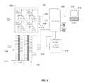
- FIG. 2is a simplified block diagram of a particular implementation of a controller.
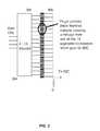
- FIG. 3is a diagram of a particular implementation of a sensor.
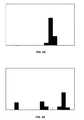
- FIGS. 4A and 4Bare bar graphs representing touch events on the sensor of FIG. 3 .
- FIG. 5Ais a diagram of another implementation of a sensor.
- FIG. 5Bis a bar graph representing a touch event on the sensor of FIG. 5A .
- FIG. 6-9are diagrams of further implementations of sensors.
- FIG. 10is a top view of a layout of an array of LEDs for use with a particular implementation of a controller.
- FIGS. 11A and 11Billustrate a drive current and a drive circuit for driving LEDs associated with a particular implementation of a controller.
- FIG. 12shows two different configurations of an array of control pads of a particular implementation of a controller.
- FIGS. 13-17show examples of interfaces for facilitating configuration of a controller to interact with a variety of software applications.
- Various implementationsprovide a highly configurable controller that includes a number of different types of control mechanisms that emulate a wide variety of conventional control mechanisms (e.g., buttons, sliders, pads, rotary controls, etc.) using pressure and location sensitive sensors that generate high-density control information which may be mapped to the controls of a wide variety of devices and software.
- control mechanismse.g., buttons, sliders, pads, rotary controls, etc.
- pressure and location sensitive sensorsthat generate high-density control information which may be mapped to the controls of a wide variety of devices and software.
- QuNeo 100provides a variety of sensors, at least some of which are responsive to X and Y (position) and Z (pressure), by which a user effects control over connected software or device(s).
- the depicted implementationincludes pressure and position sensitive pads 102 , buttons/switches 104 , decks or rotary sensors 106 (e.g., to emulate spinning vinyl records), faders or sliders 108 or 110 (e.g., to emulate VU or loudness metering). Any of sensors 104 , 106 , 108 and 110 may also be sensitive to pressure.
- each of the depicted sensorsgenerates control information that may be mapped to control a wide variety of software and/or devices.
- pressure and position sensitive pads 102can be used to elicit percussive sounds that vary in timbre based on where the user strikes the pad which is analogous to real acoustic percussion instruments.
- Faders 108are analogous to volume level controls on traditional mixing boards.
- Buttons 104can be used to make selections from lists presented by a computer menu and can scroll or navigate more rapidly through the list based on how firmly the button is pushed.
- FIG. 2shows a simplified block diagram of the components of a controller such as, for example, QuNeo 100 .
- Pad 102is shown to include four voltage dividers 202 implemented with piezoresistive material, each of which generates an output signal responsive to pressure exerted on pad 102 that is reflective of the changing characteristics of the respective voltage dividers.
- the signalsare multiplexed ( 204 ) and converted to digital form ( 206 ) and then provided as input to one or more microprocessors 208 .
- Sliders 108 and 110are scanned or driven by microprocessor 208 via decoders, e.g., decoder 210 (only one of which is shown for clarity). The outputs of sliders 108 and 110 are then converted to digital form (not shown) for input to microprocessor 208 .
- Other sensorse.g., buttons 106 shown in FIG. 1 , provide input to microprocessor 208 by similar connections.
- microprocessor 208also controls an LED matrix 212 that underlies the translucent surfaces of the various sensors. A particular drive scheme for such an LED matrix is described below.
- Optional MIDI (Musical Instrument Digital Interface) input and MIDI outputare provided by which microprocessor 208 may communicate with and control various MIDI-compliant devices.
- Control information generated from the various sensorsmay also be provided over a serial link (e.g., USB link 214 ) for the control of software (e.g., on computing device 216 ) or a connected device (not shown).
- the functionalities of QuNeo 100may also be configured, programmed, or modified via USB link 214 by software residing on computing device 216 .
- USB link 214may be replaced by any suitable alternative including, for example, a wireless connection.
- Computing device 216may be any of a wide variety of computing devices including, for example, a personal computer (e.g., a laptop or desktop), a mobile device (e.g., a cell phone, smart phone, or tablet), a set top box (e.g., for cable or satellite systems), a smart television, a gaming console, etc.
- a personal computere.g., a laptop or desktop
- a mobile devicee.g., a cell phone, smart phone, or tablet
- a set top boxe.g., for cable or satellite systems
- smart televisione.g., a gaming console, etc.
- a subset of the sensorsare implemented using an array of driven or scanned conductive printed circuit board (PCB) elements alternating with conductive elements connected to a voltage reference, e.g., ground, through a resistor.
- the arrayoverlaid with a conductive pressure sensitive compressible material that may be a piezoresistive material such as, for example, germanium, polycrystalline silicon, amorphous silicon, non-woven impregnated fabric and single crystal silicon.
- FIG. 3shows a configuration of a such a sensor in which the conductive elements are arranged in a linear array to form a slider.
- the microprocessorsequentially selects and activates the driven elements (16 elements 302 are used in a particular implementation) via decoder 304 by raising its voltage to a known level (e.g., 3.3V).
- the other driven elements 302are set to ground or 0 volts.
- the common elements 306are tied to ground through a resistor.
- the driven element(s) 302 at the point of contactare connected to the surrounding common elements 306 by the overlying conductive material (not shown).
- the voltage at the junction of the common elements and the driven element(s)is thereby raised and transmitted via a multiplexer to an ADC (not shown).
- the microprocessor driving the driven elements (not shown)also sequentially measures the corresponding signal levels, e.g., the voltage at the junction of the driven element(s) and nearby common element(s), to determine whether and where a touch event occurs.
- the ADC outputcan be represented as shown in the bar graph of FIG. 4A in which the ADC output from the 16 driven elements is represented as bars along the horizontal axis.
- the overlying material that connects the sensor resistive elementsis a piezoresistive material
- processing of this data by the microprocessoryields both pressure information (e.g., the sum of all raised data points) and location information (e.g., the centroid of the data points).
- the positional resolution derived from the arraymay be much greater than the number of elements, i.e., interpolation between the data values using a centroid calculation or similar method yields greater positional accuracy than simply using the locations of the array elements. For example, if the ADC converter that measures the voltages of 16 driven elements is 8 bits the positional resolution is theoretically 1 part in 256 for each of the 16 element locations, or 1 part in 4096 for the array using a simple interpolation approach.
- driven/scanned sensorscan be configured to recognize multiple touch points.
- the graph of FIG. 4Billustrates ADC values for three fingers exerting pressure on the linear array of elements at different locations. Height and number of element voltage values map directly to the pressure applied.
- user interface gesturessuch as pinch and stretch and multiple finger swipes can be extracted from the sensor array along with pressure for each of the contact points.
- resistive elementsthat yield information about different styles of human gesture. For example, if the elements are arranged in a linear array as shown in FIG. 3 a slider may be implemented. If the elements are arranged in a two-dimensional array (e.g., a circular or rectilinear array) information about motion in two-dimensions, e.g., rotary motion, can be extracted.
- a two-dimensional arraye.g., a circular or rectilinear array
- FIG. 5Ashows an example of a two-dimensional array 500 of PCB conductive elements arranged in a circular pattern.
- sixteen driven elementsalternate with sixteen common elements.
- the principle of operation of a sensor using array 500is similar to the sensor described above with reference to FIG. 3 , with the circuitry for driving and measuring signal levels (not shown) being substantially the same.
- each of the driven elementscan be driven to an active voltage while the common elements are tied together and biased to a reference, e.g., ground, through a resistor.
- the entire circular areais covered with a compressible conductive and/or piezoresistive material.
- the microprocessorreads the ADC values for each of the 16 driven elements, high-resolution rotational or angular position along with the pressure of the activating finger or object may be determined using, for example, interpolation techniques as mentioned above.
- Analyzing the spread of data values using known statistical methodsmay provide information related to the location of the touch event with respect to the center of circular array 500 . This can be expressed as the radius of the gesturing finger. According to a particular implementation, the radial “slices” converge in the center of the array to a radius approximating the size of the activating source, e.g., such as 4-5 mm for a human finger. In the bar graph of FIG. 5B , the ADC output for all of the driven elements shows some voltage associated with their activation. As these approach an equal amount from all radial elements the microprocessor can determine that the finger is in the center of the circular array. In addition, for implementations in which the overlying material is piezoresistive, the summed height or voltage of all elements is substantially proportional to pressure.
- FIG. 6Another sensor that may be used with various implementations of a controller as described herein is illustrated in FIG. 6 .
- a piezoresistive material(not shown) overlies an array 600 of concentric conductive traces, a subset of which are discontinuous and divided into four quadrants.
- this arrangementis configured to provide both positional information (e.g., X and Y or in the plane of the page), as well as pressure information (e.g., Z or into the page) regarding a touch event.
- This arrangement of conductive tracesmay be used to implement, for example, sensor pads 102 shown in FIGS. 1 and 2 .
- Each of four quadrants of 90 degreesincludes discontinuous conductive traces 602 spanning about 90 degrees of arc that are connected to each other and tied to a reference voltage through a resistor (e.g., 10K ohm) and to an ADC through a multiplexer (e.g., as shown in FIG. 2 ).
- a resistore.g. 10K ohm
- ADCa multiplexer
- Alternating with the discontinuous quadrant traces in the radial directionare continuous concentric traces 604 that are at some reference, e.g., ground or 0 Volts.
- the pattern of tracesis covered with a compressible piezoresistive material (not shown).
- the conductive trace of the four quadrantsare connected to the reference voltage (via the piezoresistive material) to varying degrees.
- the location chosen by the user and the pressure exerted in that positioncan be determined by a microprocessor (e.g., 208 ) through a comparison and evaluation of the signal levels present in each of the quadrants.
- a microprocessore.g., 208
- this arrangementcan provide a very high density of control information that may be mapped to a wide variety of applications.
- the control information generated using such a sensormay be used to control a cursor or pointer, or the depicted point of view, in the user interface of a computing device.
- this arrangementmay also be flexibly configured to operate as a single sensor or as multiple sensors.
- FIG. 7shows an arrangement of conductive PCB traces for implementing another type of sensor that allows measurement of pressure at a specific point.
- simple switchese.g., “On/Off” buttons
- a pattern of traces 700 covered with the piezoresistive material(not shown).
- One of traces 702 and 704is pulled up to a reference while the other pull down to another reference.
- the resistance between the conductors 702 and 704decreases and the voltage to the ADC changes correspondingly.
- Applications of such a sensorinclude, for example, pressure controlled scrolling rates when doing selection of items in a user interface, or pressure-sensitive control of musical parameters.
- the geometry, density, opacity and coating of an silicone layer overlying the sensorsmay be controlled to accomplish any subset of the following: (1) hold the piezoresistive material at a specified distance from the trace patterns; (2) deform evenly over the length, diameter or area of the specific sensor providing a linear and even response; (3) transfer the luminance from an LED indicator over the top of the sensor area; (4) diffuse the LED indicator light so it does not appear as a point; (5) protect the piezoresistive material, LED, trace and/or electronic components underneath; and/or (6) provide an appropriate tactile surface so the finger can slide or grip in a manner appropriate for how the specific sensor is activated.
- FIG. 8An example of the relationship of a silicone layer to an underlying sensor configuration is shown in FIG. 8 .
- the sensor configurationis a circular array 800 of driven/scanned conductive elements, e.g., as discussed above with reference to FIG. 5A .
- Recessing the piezoresistive material 802 into the silicone layer 804 above the conductive elements on PCB 805keeps the piezoresistive material 802 slightly off contact with the conductive elements (e.g., about 0.008′′) which creates a distinctive change in the values read by the ADC when the silicone layer above a given area of the sensor is touched.
- Increasing pressure on the siliconeincreases the readings of the ADC.
- Keeping the piezoresistive material close to the conductive elements with a sufficient silicone layer above the piezoresistive materialfacilitates transfer of the light from indicator LEDS 806 over the top of the conductive elements.
- FIG. 8also shows a cross-sectional view of a silicone layer 808 with piezoresistive material 810 in a recess in the underside of silicone layer 808 .
- the viewillustrates a taper 812 on either side of the piezoresistive material (also present in the cross-sectional view including elements 802 and 804 ) that allows silicone layer 808 to travel when compressed.
- this cross-sectionis not to scale, and may be illustrative of the relationships between the piezoresistive material and the silicone layer for any of the sensors of any of the implementations described herein.
- position and pressure information generated using appropriately configured sensorsmay be used to provide sophisticated types of control.
- changes in position and/or pressure on a particular sensormay be used to modulate control information around one or more quantized states associated with the sensor.
- a particular example in the context of a musical effects controlleris when a sensor is configured as a piano or synthesizer key.
- changes in position and/or pressuree.g., when the user wiggles or slides his finger back and forth, can be used to distort or modulate the pitch of the primary note associated with the key, e.g., to effect note bending or vibrato.
- a two-sector sensor 902is implemented to have a top and a bottom sector of a key, e.g., the top and bottom halves each having a sensor implemented as described with reference to FIG. 6 or 7 .
- the silicone keypad 904has two recesses 906 and 908 in the underside of the keypad for holding piezoresistive elements, e.g., piezoresistive discs 910 .
- the keyWhen the key is activated, e.g., by a touch event, one or both of the piezoresistive discs contact the underlying conductive elements of the sensor(s), and the control information is mapped to the primary quantized state associated with the key, i.e., the corresponding note is reproduced.
- An initial absolute valueis generated representing the difference between the signal(s) generated by the top and bottom sensors.
- An offsetis added to the initial absolute value to define an activation threshold. After a period of delay from when the key is first declared active, real-time absolute values calculated like the initial value are streamed from the key and compared to the activation threshold.
- the microprocessormaps the correspondingly modulated control information received from the key (i.e., the pressure and/or position information) to the desired effect, e.g., note bending, vibrato, etc.
- At least some implementationsinclude an array of LEDs to illuminate the sensor array and employ a scheme for driving the array in a way that allows hundreds of LEDs to be driven off limited current, e.g., the current available from a USB connection.
- a particular implementation of a controllere.g., QuNeo 100 of FIG. 1
- LED array 900is a PCB layout in which various of the LEDs may be selectively illuminated, e.g., under control of a microprocessor (not shown).
- One of the design requirements of the depicted implementationis that the controller be safely powered from a USB-2 device host or supply.
- the electrical specifications for USB-2include 5V power rails capable of providing up to 500 mA of current for a total of 2.5 watts.
- a practical way to control 251 LEDsis to create a 16 by 16 matrix that sources and sinks current for groups of 16 LEDs at a time. This reduces the best case duty cycle or time that the LED is on to 1/16th.
- Regular efficiency LEDsare 1 ⁇ 3rd the cost of high efficiency LEDs and the LED cost is the dominant component of the product's overall component cost.
- One problemis how to gain maximum brightness without exceeding the 2.5 watts of available USB power using standard efficiency LEDs; particularly given the fact that not all of this 2.5 watts can be dedicated to LED illumination as the QuNeo must perform other functions.
- Providing the 16 LEDs with a maximum of 30 mA of current at the 1/16th duty cyclemay result in a display that is insufficiently bright for many applications.
- a drive circuitis provided for accomplishing the drive current shown in FIG. 10A for each LED within a matrix of source rows and sink columns.
- FIG. 10BOne implementation of such a drive circuit is shown in FIG. 10B .
- the parallel R and C associated with each LEDprovides a brief near DC path to ground creating a limited current spike for each of the LEDs when switched on from an off state.
- the duration of the spikeis limited by the charge time of the capacitor, no other supervisory or switching circuitry is required, no increase in processor overhead is created, and component cost is minimal.
- This designnot only increases the brightness of the LEDs, it also allows LED refresh cycles to be much shorter than they would otherwise have to be in order to create the desired level of brightness. This possibility of fast refresh rates allows opportunities for more sophisticated display techniques (such as dimming and color-mixing) that are normally only possible with a costly and component-heavy design.
- the default refresh rate for a 16 ⁇ 16 LED matrixis ⁇ 1000 Hz.
- the LEDsmay be dimmed in a controllable manner. 1000 Hz also allows 16 levels of brightness as well as Off, with no discernible flickering perceived even at low brightness levels. This feature allows the device to respond to a wide range of inputs with a complex and nuanced visual display without exceeding current limit requirements or adding significantly to the cost of the controller.
- an array of sixteen 4-quadrant QuNeo sensorsmay be configured to operate as either a 4 ⁇ 4 sensor array (e.g., array 1102 ) or an 8 ⁇ 8 sensor array (e.g., array 1104 ), thus combining the functionality of both types of conventional controllers in a single device. That is, because each of the 16 pads of a particular QuNeo implementation may behave as a positional sensor and includes bicolor LEDs in each corner, each pad can operate as a single sensor, e.g., as a drum-style trigger, or as a set of four pressure-sensitive switches, thus providing the utility of both a 4 ⁇ 4 array and an 8 ⁇ 8 array.
- the LEDsmay be selectively illuminated to provide visual feedback to the user as to the current configuration.
- QuNeomay be configured to power up with presets that emulate the functionality of popular drum pad and grid controllers.
- QuNeomay behave like an Akai MPD/MPC pad controller configured for dynamic electronic drumming and pad based sequencing.
- QuNeomay be set up similar to a standard drum pad controller, with four sets of notes from C2 to E7. An appropriate velocity value may be associated with each note. 16 notes may be playable (1 per pad), e.g., starting from the bottom left and ascending chromatically to the right and toward the top.
- the QuNeomay emulate popular 8 ⁇ 8 grid based controllers like the Monome and Novation's Launchpad. Monome style sequencing and sample manipulation is readily emulated, with the added bonus of pressure output for each of the 64 steps.
- clip launching in Ableton Liveis also easily supported while operating as a grid controller, with 64 possible clips per bank.
- Multi color LEDsalso in an 8 ⁇ 8 grid, may act as indicators for beats and playing/recording.
- QuNeomay be configured to work with a wide variety of third-party software and/or devices. This versatility is enabled through the installation of ancillary code into the third-party software to enable the mapping of QuNeo's high-density control information to existing music applications, e.g., synthesizers, DJ applications, recording applications, etc.
- QuNeohave a variety of associated templates that allow QuNeo to integrate and work with the various third-party software. These templates facilitate installation of Python script code into the third-party software that maps the QuNeo control information to the inputs recognized by the interface stack of the third-party software.
- the QuNeo softwareis activated (e.g., on a user's PC as downloaded from the web)
- the useris presented with a list of third-party software.
- the installerfinds the selected software and installs the necessary scripts.
- Corresponding manualsmay also be loaded which explain how to use the QuNeo to control the selected software.
- QuNeohas the potential to interface with many different software applications since it is a class-compliant MIDI device with control information mappings to complement many of the most popular pieces of software.
- QuNeo softwaree.g., downloaded to his PC from the web
- the useris prompted to select from among the available software templates as shown in screenshot 1200 of FIG. 12 .
- Each option on the listhas an associated group of files that save the user setup time, providing an easy “out-of-box” experience for the user in connecting QuNeo with their favorite software application.
- an Ableton Live example fileis put into the user's install directory along with an automatically installed QuNeo Editor and associated documentation.
- the example fileincludes sounds the user can try out to illustrate the way in which QuNeo is initially set up to control the Ableton Live software.
- Selection of the Ableton Live templatealso results in installation of a group of remote mapping files. These mapping files control which of the application's functions are triggered when data are received from QuNeo. For example, when a certain button on QuNeo is pressed, the application's play button is triggered).
- the mapping filesare Python scripts.
- the mapping file formatmay vary from application to application.
- the installerplaces the remote mapping files in a location on the user's computer where the corresponding application can find them and interact with them accordingly.
- the locationmay be a default, in the user's Applications folder on a Mac. Alternatively, this may be accomplished by asking the user to browse to a particular directory—usually to the location of the selected application itself—as shown in screenshot 1300 of FIG. 13 .
- the Python scriptsgo into a folder within the application where other supported controller scripts typically exist (e.g., as shown in screenshot 1400 of FIG. 14 ). In this way, the application will then recognize QuNeo as a supported control surface when it is next launched.
- a copy of the remote mapping filesmay also be placed in the install directory in case there is an error during installation, if the user wants to manually add the files to a different version of Ableton Live, or in case they are just curious to look at them.
- the install directorymight end up looking like screenshot 1500 of FIG. 15 .
- the folder Ableton Live 1.1contains the folder Installation Files (which holds the extra copy of the Ableton Live remote mapping files), the Quickstart guides documenting how to use the Ableton Live template, and the example file containing sounds for the user to try out (“QuNeoDemo Project”).
- the computer program instructions with which embodiments of the invention may be implementedmay correspond to any of a wide variety of programming languages, software tools and data formats, and be stored in any type of volatile or nonvolatile, non-transitory computer-readable storage medium or memory device, and may be executed according to a variety of computing models including, for example, a client/server model, a peer-to-peer model, on a stand-alone computing device, or according to a distributed computing model in which various of the functionalities may be effected or employed at different locations.
- reference to particular protocols hereinare merely by way of example. Suitable alternatives known to those of skill in the art may be employed without departing from the scope of the invention.
Landscapes
- Engineering & Computer Science (AREA)
- Theoretical Computer Science (AREA)
- Physics & Mathematics (AREA)
- General Engineering & Computer Science (AREA)
- Human Computer Interaction (AREA)
- General Physics & Mathematics (AREA)
- Acoustics & Sound (AREA)
- Multimedia (AREA)
- User Interface Of Digital Computer (AREA)
Abstract
Description
Claims (35)
Priority Applications (5)
| Application Number | Priority Date | Filing Date | Title |
|---|---|---|---|
| US13/799,304US9076419B2 (en) | 2012-03-14 | 2013-03-13 | Multi-touch pad controller |
| US14/728,872US9836151B2 (en) | 2012-03-14 | 2015-06-02 | Multi-touch pad controller |
| US14/728,873US10114493B2 (en) | 2012-03-14 | 2015-06-02 | Multi-touch pad controller |
| US16/148,570US10802641B2 (en) | 2012-03-14 | 2018-10-01 | Piezoresistive sensors and applications |
| US16/948,131US11204664B2 (en) | 2012-03-14 | 2020-09-03 | Piezoresistive sensors and applications |
Applications Claiming Priority (2)
| Application Number | Priority Date | Filing Date | Title |
|---|---|---|---|
| US201261610924P | 2012-03-14 | 2012-03-14 | |
| US13/799,304US9076419B2 (en) | 2012-03-14 | 2013-03-13 | Multi-touch pad controller |
Related Child Applications (2)
| Application Number | Title | Priority Date | Filing Date |
|---|---|---|---|
| US14/728,873ContinuationUS10114493B2 (en) | 2012-03-14 | 2015-06-02 | Multi-touch pad controller |
| US14/728,872ContinuationUS9836151B2 (en) | 2012-03-14 | 2015-06-02 | Multi-touch pad controller |
Publications (2)
| Publication Number | Publication Date |
|---|---|
| US20130239787A1 US20130239787A1 (en) | 2013-09-19 |
| US9076419B2true US9076419B2 (en) | 2015-07-07 |
Family
ID=49156462
Family Applications (5)
| Application Number | Title | Priority Date | Filing Date |
|---|---|---|---|
| US13/799,304Active2033-12-06US9076419B2 (en) | 2012-03-14 | 2013-03-13 | Multi-touch pad controller |
| US14/728,872ActiveUS9836151B2 (en) | 2012-03-14 | 2015-06-02 | Multi-touch pad controller |
| US14/728,873ActiveUS10114493B2 (en) | 2012-03-14 | 2015-06-02 | Multi-touch pad controller |
| US16/148,570Active2033-05-05US10802641B2 (en) | 2012-03-14 | 2018-10-01 | Piezoresistive sensors and applications |
| US16/948,131ActiveUS11204664B2 (en) | 2012-03-14 | 2020-09-03 | Piezoresistive sensors and applications |
Family Applications After (4)
| Application Number | Title | Priority Date | Filing Date |
|---|---|---|---|
| US14/728,872ActiveUS9836151B2 (en) | 2012-03-14 | 2015-06-02 | Multi-touch pad controller |
| US14/728,873ActiveUS10114493B2 (en) | 2012-03-14 | 2015-06-02 | Multi-touch pad controller |
| US16/148,570Active2033-05-05US10802641B2 (en) | 2012-03-14 | 2018-10-01 | Piezoresistive sensors and applications |
| US16/948,131ActiveUS11204664B2 (en) | 2012-03-14 | 2020-09-03 | Piezoresistive sensors and applications |
Country Status (1)
| Country | Link |
|---|---|
| US (5) | US9076419B2 (en) |
Cited By (19)
| Publication number | Priority date | Publication date | Assignee | Title |
|---|---|---|---|---|
| US9442614B2 (en) | 2014-05-15 | 2016-09-13 | Bebop Sensors, Inc. | Two-dimensional sensor arrays |
| US9546921B2 (en) | 2009-10-16 | 2017-01-17 | Bebop Sensors, Inc. | Piezoresistive sensors and sensor arrays |
| US20170092249A1 (en)* | 2014-05-19 | 2017-03-30 | Skoogmusic Ltd | Control apparatus |
| US9696833B2 (en) | 2014-05-15 | 2017-07-04 | Bebop Sensors, Inc. | Promoting sensor isolation and performance in flexible sensor arrays |
| US9710060B2 (en) | 2014-06-09 | 2017-07-18 | BeBop Senors, Inc. | Sensor system integrated with a glove |
| US9721553B2 (en) | 2015-10-14 | 2017-08-01 | Bebop Sensors, Inc. | Sensor-based percussion device |
| US9753568B2 (en) | 2014-05-15 | 2017-09-05 | Bebop Sensors, Inc. | Flexible sensors and applications |
| US9827996B2 (en) | 2015-06-25 | 2017-11-28 | Bebop Sensors, Inc. | Sensor systems integrated with steering wheels |
| US9836151B2 (en) | 2012-03-14 | 2017-12-05 | Bebop Sensors, Inc. | Multi-touch pad controller |
| US9863823B2 (en) | 2015-02-27 | 2018-01-09 | Bebop Sensors, Inc. | Sensor systems integrated with footwear |
| US9965076B2 (en)* | 2014-05-15 | 2018-05-08 | Bebop Sensors, Inc. | Piezoresistive sensors and applications |
| US10082381B2 (en) | 2015-04-30 | 2018-09-25 | Bebop Sensors, Inc. | Sensor systems integrated with vehicle tires |
| KR20190054017A (en) | 2017-11-11 | 2019-05-21 | 박성민 | Wireless Launchpad |
| US20190197999A1 (en)* | 2017-12-25 | 2019-06-27 | Casio Computer Co., Ltd. | Operation state detecting apparatus, operation state detecting sheet, and electronic instrument |
| US10362989B2 (en) | 2014-06-09 | 2019-07-30 | Bebop Sensors, Inc. | Sensor system integrated with a glove |
| US10690312B2 (en) | 2017-05-18 | 2020-06-23 | Tri Lite, Inc. | Light emitting diode signal light |
| US10884496B2 (en) | 2018-07-05 | 2021-01-05 | Bebop Sensors, Inc. | One-size-fits-all data glove |
| US11480481B2 (en) | 2019-03-13 | 2022-10-25 | Bebop Sensors, Inc. | Alignment mechanisms sensor systems employing piezoresistive materials |
| WO2023070142A1 (en) | 2021-10-28 | 2023-05-04 | Birdkids Gmbh | Portable digital audio device for capturing user interactions |
Families Citing this family (38)
| Publication number | Priority date | Publication date | Assignee | Title |
|---|---|---|---|---|
| US8563843B1 (en)* | 2010-01-13 | 2013-10-22 | Guy Shemesh | Electronic percussion device and method |
| USD706230S1 (en)* | 2012-03-02 | 2014-06-03 | Kesumo Llc | Musical controller |
| EP2830039B1 (en)* | 2013-07-24 | 2018-10-03 | Native Instruments GmbH | Method, arrangement, computer program and computer-readable storage means for controlling at least one parameter or at least one object using capacity sensing input elements |
| US20160098128A1 (en)* | 2014-05-09 | 2016-04-07 | T+Ink, Inc. | Input devices and related systems and methods |
| US20160026341A1 (en)* | 2014-07-22 | 2016-01-28 | Igor Kraev | Matrix interface for enabling access to digital content |
| KR101720525B1 (en)* | 2014-10-03 | 2017-03-28 | 주식회사 임프레시보코리아 | Audio system enabled by device for recognizing user operation |
| USD763827S1 (en) | 2015-01-15 | 2016-08-16 | Kesumo, Llc | Audio mixing device |
| US10281948B2 (en)* | 2015-06-25 | 2019-05-07 | Giordano P. Jacuzzi | Multi-operational music hardware controller |
| US20170011405A1 (en)* | 2015-07-09 | 2017-01-12 | Mastercard International Incorporated | Simultaneous multi-factor authentication systems and methods for payment transactions |
| KR102432792B1 (en) | 2015-08-10 | 2022-08-17 | 삼성전자주식회사 | Electronic apparatus and operating method thereof |
| KR102398315B1 (en) | 2015-08-11 | 2022-05-16 | 삼성전자주식회사 | Electronic device and method for reproduction of sound in the electronic device |
| CN106802732A (en)* | 2015-11-25 | 2017-06-06 | 中兴通讯股份有限公司 | Object selection method and device |
| US9640158B1 (en) | 2016-01-19 | 2017-05-02 | Apple Inc. | Dynamic music authoring |
| GB2551502A (en)* | 2016-06-17 | 2017-12-27 | M-Solv Ltd | Apparatus and methods for manufacturing a sensor and a display, and a sensor and a display |
| CA2950504A1 (en) | 2016-11-01 | 2018-05-01 | ROLI Limited | User interface device |
| GB2555589A (en) | 2016-11-01 | 2018-05-09 | Roli Ltd | Controller for information data |
| USD846527S1 (en)* | 2016-11-01 | 2019-04-23 | Roli Ltd. | Control block |
| US10770048B2 (en)* | 2017-05-12 | 2020-09-08 | Lafayette College | Analog synthesizer patch morphing and simultaneous parameter control though input devices |
| US12210707B2 (en) | 2018-01-08 | 2025-01-28 | Kids Ii Hape Joint Venture Limited | Toys with connected play |
| EP3848103B1 (en) | 2018-01-08 | 2022-12-07 | Kids II Hape Joint Venture Limited | Children's toys with capacitive touch interactivity |
| US12100376B2 (en) | 2018-09-27 | 2024-09-24 | Inmusic Brands, Inc. | Musical step sequencer and controller |
| USD945535S1 (en) | 2019-01-07 | 2022-03-08 | Kids Ii Hape Joint Venture Limited | Children's play table |
| CN109686350A (en)* | 2019-01-16 | 2019-04-26 | 天津大学 | A kind of SCM Based modular portable music percussion pad |
| US11295714B2 (en)* | 2019-01-17 | 2022-04-05 | Inmusic Brands, Inc. | System and method for music production |
| US20220190044A1 (en)* | 2019-02-22 | 2022-06-16 | Peratech Holdco Ltd | Light-emitting apparatus |
| CN110677814B (en)* | 2019-05-09 | 2020-11-17 | 杨丽 | Wireless communication method based on density analysis |
| CN110401968B (en)* | 2019-05-09 | 2020-05-22 | 温州曼昔维服饰有限公司 | Wireless Communication System Based on Density Analysis |
| US10984770B2 (en)* | 2019-06-06 | 2021-04-20 | Jared Sidney Simon | Integrated Melodic Instrument Digital Interface (MIDI) Controller within a laptop chassis |
| US11056088B2 (en)* | 2019-11-15 | 2021-07-06 | Inmusic Brands, Inc. | System and method for grouping audio events in an electronic percussion device |
| US11120781B2 (en)* | 2019-11-15 | 2021-09-14 | Inmusic Brands, Inc. | System and method for a visualizing characteristics of an audio event |
| FR3103341B1 (en)* | 2019-11-20 | 2022-07-22 | Embodme | SYSTEM FOR GENERATING A SIGNAL FROM A TOUCH CONTROL AND AN OPTICAL CONTROL |
| USD952756S1 (en) | 2019-11-25 | 2022-05-24 | Kids Ii Hape Joint Venture Limited | Musical toy |
| GB2593493B (en)* | 2020-03-24 | 2022-05-25 | Kano Computing Ltd | Audio output device |
| USD979656S1 (en) | 2020-12-11 | 2023-02-28 | Kids Ii Hape Joint Venture Limited | Toy drum |
| EP4019926A1 (en)* | 2020-12-22 | 2022-06-29 | Max-Planck-Gesellschaft zur Förderung der Wissenschaften e.V. | System and method for simultaneously sensing contact force and lateral strain |
| USD985677S1 (en) | 2021-01-11 | 2023-05-09 | Kids Ii Hape Joint Venture Limited | Toy guitar |
| USD985676S1 (en) | 2021-01-11 | 2023-05-09 | Kids Ii Hape Joint Venture Limited | Toy drum |
| US12106743B1 (en) | 2023-11-17 | 2024-10-01 | Chord Board, Llc | Beat player musical instrument |
Citations (24)
| Publication number | Priority date | Publication date | Assignee | Title |
|---|---|---|---|---|
| US4852443A (en) | 1986-03-24 | 1989-08-01 | Key Concepts, Inc. | Capacitive pressure-sensing method and apparatus |
| US5131306A (en) | 1989-01-19 | 1992-07-21 | Yamaha Corporation | Automatic music playing piano |
| US5288938A (en) | 1990-12-05 | 1994-02-22 | Yamaha Corporation | Method and apparatus for controlling electronic tone generation in accordance with a detected type of performance gesture |
| US5429092A (en) | 1993-02-25 | 1995-07-04 | Mitsubishi Denki Kabushiki Kaisha | Throttle control system |
| JPH08194481A (en) | 1995-01-13 | 1996-07-30 | Roland Corp | Editing method with foot controller |
| US5866829A (en) | 1996-12-20 | 1999-02-02 | Pecoraro; Thomas | Pedal rack |
| US5878359A (en) | 1995-06-09 | 1999-03-02 | Nipponsenso Co., Ltd. | Vehicular control device provided with an accelerator detecting device which detects the operation of an accelerator device |
| US5943044A (en)* | 1996-08-05 | 1999-08-24 | Interlink Electronics | Force sensing semiconductive touchpad |
| JP2000267664A (en) | 1999-03-16 | 2000-09-29 | Yamaha Corp | Playing data processing system |
| US6215055B1 (en) | 1997-08-06 | 2001-04-10 | Darren Saravis | Foot pedal boards for musical instruments |
| US6216545B1 (en) | 1995-11-14 | 2001-04-17 | Geoffrey L. Taylor | Piezoresistive foot pressure measurement |
| US7157640B2 (en) | 2003-06-17 | 2007-01-02 | Baggs Lloyd R | Undersaddle pickup for stringed musical instrument |
| US20070234888A1 (en) | 2005-10-03 | 2007-10-11 | Audiobrax Industria E Comercio De Produtos Eletronicos S/A | Rhythmic device for the production, playing, accompaniment and evaluation of sounds |
| US7332670B2 (en) | 2004-07-27 | 2008-02-19 | Yamaha Corporation | Automatic player exactly bringing pedal to half point, musical instrument equipped therewith and method used therein |
| JP2008515008A (en) | 2004-10-01 | 2008-05-08 | オーディオブラックス インドゥストリア エ コメルシオ デ プロドゥトス エレトロニコス ソシエダッド アノニマ | Rhythm device for sound generation, performance, accompaniment and evaluation |
| US20080158145A1 (en) | 2007-01-03 | 2008-07-03 | Apple Computer, Inc. | Multi-touch input discrimination |
| US20080254824A1 (en) | 2005-02-02 | 2008-10-16 | Aurelio Rotolo Moraes | Mobile Communication Device with Musical Instrument Functions |
| US20090049980A1 (en) | 2003-07-25 | 2009-02-26 | Ravi Sharma | Inverted keyboard instrument and method of playing the same |
| US20090237374A1 (en) | 2008-03-20 | 2009-09-24 | Motorola, Inc. | Transparent pressure sensor and method for using |
| US7608776B2 (en) | 2003-12-15 | 2009-10-27 | Ludwig Lester F | Modular structures facilitating field-customized floor controllers |
| US7754956B2 (en) | 2007-12-12 | 2010-07-13 | Force Ten International Llc | Programmable system to integrate generated signals with signals from a musical instrument |
| US20100315337A1 (en) | 2009-06-16 | 2010-12-16 | Bran Ferren | Optical capacitive thumb control with pressure sensor |
| WO2011047171A2 (en) | 2009-10-16 | 2011-04-21 | Kesumo, Llc | Foot-operated controller |
| US20110088535A1 (en) | 2008-03-11 | 2011-04-21 | Misa Digital Pty Ltd. | digital instrument |
Family Cites Families (295)
| Publication number | Priority date | Publication date | Assignee | Title |
|---|---|---|---|---|
| JPS5031615Y2 (en) | 1971-03-31 | 1975-09-16 | ||
| NL7900596A (en) | 1979-01-25 | 1980-07-29 | Stichting Voet En Schoeisel | FOOT MEASUREMENT. |
| DE2912038C2 (en) | 1979-03-27 | 1981-09-17 | Bidegain S.A., Pau, Basses-Pyrenees | Arrangement for determining the shoe size corresponding to a foot |
| US4489302A (en)* | 1979-09-24 | 1984-12-18 | Eventoff Franklin Neal | Electronic pressure sensitive force transducer |
| JPS58126227A (en) | 1982-01-21 | 1983-07-27 | Nissan Motor Co Ltd | Seat slide device for car |
| US4438291A (en) | 1982-03-08 | 1984-03-20 | General Electric Company | Screen-printable thermocouples |
| US4734034A (en) | 1985-03-29 | 1988-03-29 | Sentek, Incorporated | Contact sensor for measuring dental occlusion |
| ATE77164T1 (en) | 1985-08-19 | 1992-06-15 | Jaron Z Lanier | APPARATUS FOR ENTERING AND HANDLING COMPUTER DATA. |
| US4790968A (en) | 1985-10-19 | 1988-12-13 | Toshiba Silicone Co., Ltd. | Process for producing pressure-sensitive electroconductive sheet |
| US4745301A (en) | 1985-12-13 | 1988-05-17 | Advanced Micro-Matrix, Inc. | Pressure sensitive electro-conductive materials |
| US4693530A (en) | 1986-09-29 | 1987-09-15 | Amp Incorporated | Shielded elastomeric electric connector |
| NL8900820A (en) | 1989-04-04 | 1990-11-01 | Hoogstraat Med Tech | Automatic shoe size measuring appts. - measures both inside and outside dimensions using sensors supplying microprocessor |
| US5033291A (en) | 1989-12-11 | 1991-07-23 | Tekscan, Inc. | Flexible tactile sensor for measuring foot pressure distributions and for gaskets |
| JP2605163B2 (en) | 1990-04-27 | 1997-04-30 | 東芝シリコーン株式会社 | Silicone ink |
| US5237520A (en) | 1990-05-11 | 1993-08-17 | Foot Image Technology, Inc. | Foot measurement and footwear sizing system |
| US5128880A (en) | 1990-05-11 | 1992-07-07 | Foot Image Technology, Inc. | Foot measurement and footwear sizing system |
| JPH0797057B2 (en)* | 1990-07-06 | 1995-10-18 | 株式会社エニックス | Surface pressure distribution detection element |
| US5159159A (en) | 1990-12-07 | 1992-10-27 | Asher David J | Touch sensor and controller |
| US5232243A (en) | 1991-04-09 | 1993-08-03 | Trw Vehicle Safety Systems Inc. | Occupant sensing apparatus |
| US5386720A (en) | 1992-01-09 | 1995-02-07 | Olympus Optical Co., Ltd. | Integrated AFM sensor |
| US5219292A (en) | 1992-04-03 | 1993-06-15 | Motorola, Inc. | Printed circuit board interconnection |
| US5361133A (en) | 1992-06-23 | 1994-11-01 | Footmark, Inc. | Method and apparatus for analyzing feet |
| US5790256A (en) | 1992-06-23 | 1998-08-04 | Footmark, Inc. | Foot analyzer |
| US5316017A (en) | 1992-10-07 | 1994-05-31 | Greenleaf Medical Systems, Inc. | Man-machine interface for a joint measurement system |
| JP2719090B2 (en) | 1993-05-13 | 1998-02-25 | グンゼ株式会社 | Wearing pressure measuring device |
| DE4334040C2 (en) | 1993-10-06 | 1996-07-11 | Klippel Wolfgang | Circuit arrangement for the independent correction of the transmission behavior of electrodynamic sound transmitters without an additional mechanical or acoustic sensor |
| US6087930A (en) | 1994-02-22 | 2000-07-11 | Computer Methods Corporation | Active integrated circuit transponder and sensor apparatus for transmitting vehicle tire parameter data |
| JP2536446B2 (en) | 1994-04-05 | 1996-09-18 | 日本電気株式会社 | Force detection display |
| US5571973A (en) | 1994-06-06 | 1996-11-05 | Taylot; Geoffrey L. | Multi-directional piezoresistive shear and normal force sensors for hospital mattresses and seat cushions |
| JPH0871978A (en) | 1994-06-27 | 1996-03-19 | Olympus Optical Co Ltd | Manipulator |
| US5695859A (en) | 1995-04-27 | 1997-12-09 | Burgess; Lester E. | Pressure activated switching device |
| US6029358A (en) | 1995-09-11 | 2000-02-29 | Dwayne L. Mason | Solid state digital electronic shoe sizer |
| US5729905A (en) | 1995-09-11 | 1998-03-24 | Dwayne L. Mason | Foot measuring apparatus and circuitry to eliminate multiplexes and demultiplexers |
| US5989700A (en) | 1996-01-05 | 1999-11-23 | Tekscan Incorporated | Pressure sensitive ink means, and methods of use |
| WO1998020615A2 (en) | 1996-10-21 | 1998-05-14 | Electronics Development Corporation | Smart sensor module |
| US5854625A (en) | 1996-11-06 | 1998-12-29 | Synaptics, Incorporated | Force sensing touchpad |
| US6049327A (en) | 1997-04-23 | 2000-04-11 | Modern Cartoons, Ltd | System for data management based onhand gestures |
| US5822223A (en) | 1997-08-05 | 1998-10-13 | Genovation Inc. | Electronic foot measuring apparatus |
| US6687523B1 (en) | 1997-09-22 | 2004-02-03 | Georgia Tech Research Corp. | Fabric or garment with integrated flexible information infrastructure for monitoring vital signs of infants |
| US6486776B1 (en) | 1998-04-14 | 2002-11-26 | The Goodyear Tire & Rubber Company | RF transponder and method of measuring parameters associated with a monitored object |
| US6304840B1 (en) | 1998-06-30 | 2001-10-16 | U.S. Philips Corporation | Fingerless glove for interacting with data processing system |
| LU90286B1 (en) | 1998-09-11 | 2000-03-13 | Iee Sarl | Force transducer |
| US6141643A (en) | 1998-11-25 | 2000-10-31 | Harmon; Steve | Data input glove having conductive finger pads and thumb pad, and uses therefor |
| EP1065097A4 (en) | 1999-01-27 | 2001-11-14 | Furukawa Electric Co Ltd | Occupant detecting device |
| US20040189145A1 (en) | 1999-01-28 | 2004-09-30 | Baruch Pletner | Method and device for vibration control |
| US7037268B1 (en) | 1999-03-01 | 2006-05-02 | Medacoustics, Inc. | Low profile acoustic sensor arry and sensors with pleated transmission lines and related methods |
| AU4419800A (en) | 1999-05-20 | 2000-12-12 | Electrotextiles Company Limited | Detector constructed from fabric |
| US6121869A (en) | 1999-09-20 | 2000-09-19 | Burgess; Lester E. | Pressure activated switching device |
| US6822635B2 (en) | 2000-01-19 | 2004-11-23 | Immersion Corporation | Haptic interface for laptop computers and other portable devices |
| WO2001085497A1 (en) | 2000-05-10 | 2001-11-15 | Wallace Michael W | Vehicle occupant classification system and method |
| GB0011829D0 (en) | 2000-05-18 | 2000-07-05 | Lussey David | Flexible switching devices |
| US6360615B1 (en) | 2000-06-06 | 2002-03-26 | Technoskin, Llc | Wearable effect-emitting strain gauge device |
| US6571638B2 (en) | 2000-06-30 | 2003-06-03 | Sawtek, Inc. | Surface-acoustic-wave pressure sensor and associated methods |
| US7138976B1 (en) | 2000-07-13 | 2006-11-21 | Rutgers, The State University Of New Jersey | Hand force feedback and sensing system |
| ITCT20000012U1 (en) | 2000-08-18 | 2002-02-18 | Salvatore Varsallona | FOOTWEAR MEASUREMENT EXACT DETECTION SYSTEM |
| JP3980300B2 (en) | 2000-09-07 | 2007-09-26 | 株式会社フジクラ | Membrane pressure sensitive resistor and pressure sensor |
| JP2002131155A (en) | 2000-10-30 | 2002-05-09 | Denso Corp | Pressure sensitive resistance sensor |
| JP2004538207A (en) | 2001-08-17 | 2004-12-24 | アイイーイー インターナショナル エレクトロニクス アンド エンジニアリング エス.エイ. | Vehicle seat occupancy classification method |
| US20050220673A1 (en) | 2002-02-22 | 2005-10-06 | Jacob Thaysen | Sensor comprising an array of pieroresistors |
| DE10212023A1 (en) | 2002-03-19 | 2003-10-02 | Bosch Gmbh Robert | Sensor cell, especially for use in the sensor mat of a motor vehicle seat, has a piezoelectric resistance element with at least one additional contact so that two resistance measurements are made |
| US6817130B2 (en) | 2002-06-17 | 2004-11-16 | New Jersey Institute Of Technology | Sensor array for unauthorized user prevention device |
| JP2004028883A (en) | 2002-06-27 | 2004-01-29 | Denso Corp | Pressure-sensitive sensor |
| US6763320B2 (en) | 2002-08-15 | 2004-07-13 | International Business Machines Corporation | Data input device for individuals with limited hand function |
| US6815602B2 (en) | 2002-09-30 | 2004-11-09 | Vince De Franco | Electronic percussion instrument with impact position-dependent variable resistive switch |
| US6818842B2 (en) | 2002-12-19 | 2004-11-16 | Delphi Technologies, Inc. | Seat foam humidity compensation for vehicle seat occupant weight detection system |
| US20040183648A1 (en) | 2003-03-21 | 2004-09-23 | Weber Thomas E. | Strain sensors and housings and circuit boards with integrated strain sensors |
| JP4254295B2 (en) | 2003-03-25 | 2009-04-15 | アイシン精機株式会社 | Seating detection device |
| EP1469378A1 (en) | 2003-04-16 | 2004-10-20 | IEE INTERNATIONAL ELECTRONICS & ENGINEERING S.A. | Position detection apparatus |
| EP1636071B1 (en) | 2003-06-23 | 2007-02-21 | IEE INTERNATIONAL ELECTRONICS & ENGINEERING S.A. | Seat occupancy sensor |
| US7499040B2 (en) | 2003-08-18 | 2009-03-03 | Apple Inc. | Movable touch pad with added functionality |
| JP2005069968A (en) | 2003-08-27 | 2005-03-17 | Aisin Seiki Co Ltd | Seating detection device |
| US7066887B2 (en) | 2003-10-21 | 2006-06-27 | Vermon | Bi-plane ultrasonic probe |
| JP4430381B2 (en) | 2003-11-20 | 2010-03-10 | 本田技研工業株式会社 | Occupant detection device |
| US20050109095A1 (en) | 2003-11-20 | 2005-05-26 | Sinnett Jay C. | Saw transducer interface to pressure sensing diaphragm |
| US7398688B2 (en) | 2003-12-11 | 2008-07-15 | Proteus Biomedical, Inc. | Pressure sensor circuits |
| US6964205B2 (en) | 2003-12-30 | 2005-11-15 | Tekscan Incorporated | Sensor with plurality of sensor elements arranged with respect to a substrate |
| GB0407366D0 (en) | 2004-03-31 | 2004-05-05 | Koninkl Philips Electronics Nv | Textile form touch sensor |
| JP4218614B2 (en) | 2004-08-27 | 2009-02-04 | アイシン精機株式会社 | Seat state detection device, irradiation direction adjustment device for vehicle headlamp, and seating detection device |
| US7109068B2 (en) | 2004-08-31 | 2006-09-19 | Micron Technology, Inc. | Through-substrate interconnect fabrication methods |
| US7311009B2 (en) | 2004-11-17 | 2007-12-25 | Lawrence Livermore National Security, Llc | Microelectromechanical systems contact stress sensor |
| US8109149B2 (en) | 2004-11-17 | 2012-02-07 | Lawrence Livermore National Security, Llc | Contact stress sensor |
| US20060103192A1 (en) | 2004-11-18 | 2006-05-18 | Peter Norton | Load cell and seat occupant weight sensing system |
| DE102005008591A1 (en) | 2005-02-24 | 2006-09-14 | Siemens Ag | Seat occupancy detection mat |
| WO2006101445A1 (en) | 2005-03-23 | 2006-09-28 | össur hf | System and method for conscious sensory feedback |
| DE102005018527A1 (en) | 2005-04-20 | 2006-10-26 | David Bauer | Golf training gloves |
| US20060289469A1 (en) | 2005-04-21 | 2006-12-28 | Noble Fiber Technologies Llc | Flexible electrically conductive circuits |
| US8127623B2 (en) | 2005-05-18 | 2012-03-06 | Pressure Profile Systems Inc. | Capacitive tactile tile sensor |
| US7536794B2 (en) | 2005-05-20 | 2009-05-26 | Bivab, Llc | Foot measurement, alignment and evaluation device |
| US7439962B2 (en) | 2005-06-01 | 2008-10-21 | Synaptics Incorporated | Touch pad with flexible substrate |
| US20060287140A1 (en) | 2005-06-16 | 2006-12-21 | Brandt Richard A | Automated line calling system |
| US20070043582A1 (en) | 2005-08-22 | 2007-02-22 | Fila Luxembourg S.A.R.L. | Method and system for providing customized footwear to a retail consumer |
| US7439465B2 (en) | 2005-09-02 | 2008-10-21 | White Electronics Designs Corporation | Switch arrays and systems employing the same to enhance system reliability |
| US20070063992A1 (en) | 2005-09-17 | 2007-03-22 | Lundquist Paul B | Finger-keyed human-machine interface device |
| US20070129776A1 (en) | 2005-10-20 | 2007-06-07 | Light Sciences Llc | External wearable light therapy treatment systems |
| US7409256B2 (en) | 2005-12-16 | 2008-08-05 | Industrial Technology Research Institute | Footwear measurement and footwear manufacture systems and methods |
| US7483866B2 (en) | 2005-12-19 | 2009-01-27 | Trw Automotive U.S. Llc | Subclass partitioning in a pattern recognition classifier for controlling deployment of an occupant restraint system |
| US7208960B1 (en) | 2006-02-10 | 2007-04-24 | Milliken & Company | Printed capacitive sensor |
| US7878075B2 (en) | 2007-05-18 | 2011-02-01 | University Of Southern California | Biomimetic tactile sensor for control of grip |
| US7493230B2 (en) | 2006-06-06 | 2009-02-17 | Aetrex Worldwide, Inc. | Method and apparatus for customizing insoles for footwear |
| ES2294934B1 (en) | 2006-07-06 | 2008-11-16 | Fundacio Privada Per A La Innovacio Textil D'igualada | TEXTILE SENSOR OF PRESSURE AND / OR TENSION AND / OR TORSION EFFORTS. |
| EP1883040A1 (en) | 2006-07-28 | 2008-01-30 | IEE International Electronics & Engineering S.A.R.L. | Pattern classification method |
| CN200980381Y (en) | 2006-08-31 | 2007-11-28 | 陈波 | Device for selecting shoe size according with measured foot size |
| KR20090077755A (en) | 2006-09-09 | 2009-07-15 | 에프-오리진, 인크. | Integrated Pressure Sensing Lens Assembly |
| US8175821B2 (en) | 2006-09-12 | 2012-05-08 | The University Of Tokyo | Method for measuring physical quantity distribution and measurement system using sensor for physical quantity distribution |
| US20080069412A1 (en) | 2006-09-15 | 2008-03-20 | Champagne Katrina S | Contoured biometric sensor |
| TWI440836B (en) | 2006-09-21 | 2014-06-11 | Msd Consumer Care Inc | Foot care product dispensing kiosk |
| US8117922B2 (en) | 2006-09-21 | 2012-02-21 | Msd Consumer Care, Inc. | Footcare product dispensing kiosk |
| EP2073704A1 (en) | 2006-10-11 | 2009-07-01 | Koninklijke Philips Electronics N.V. | Limb movement monitoring system |
| KR100865148B1 (en) | 2006-12-14 | 2008-10-24 | 이학범 | Foot size automatic measuring device |
| KR20070008500A (en) | 2006-12-29 | 2007-01-17 | 이학범 | Ultrasonic Foot Size Automatic Measuring System |
| US7302866B1 (en) | 2007-01-10 | 2007-12-04 | The Boeing Company | Device, system, and method for structural health monitoring |
| EP2150791B1 (en) | 2007-04-23 | 2016-03-16 | Given Imaging (Los Angeles) LLC | Suspended membrane pressure sensing array |
| CN101680819B (en) | 2007-06-20 | 2012-12-12 | 米其林研究和技术股份有限公司 | Automatic localization of all tire IDs on multi-axle vehicles |
| KR100908124B1 (en) | 2007-07-09 | 2009-07-16 | 삼성전자주식회사 | Pressure sensor for measuring blood pressure and manufacturing method thereof |
| WO2009027629A1 (en) | 2007-08-26 | 2009-03-05 | Qrg Limited | Capacitive sensor with reduced noise |
| KR100921813B1 (en) | 2007-11-07 | 2009-10-16 | 주식회사 애트랩 | Touch panel device and its contact position detection method |
| US7772960B2 (en) | 2007-11-27 | 2010-08-10 | Interlink Electronics, Inc. | Pre-loaded force sensing resistor and method |
| IL188645A (en) | 2008-01-07 | 2011-12-29 | Eliaho Gerby | Foot measuring device |
| US8161826B1 (en) | 2009-03-05 | 2012-04-24 | Stryker Corporation | Elastically stretchable fabric force sensor arrays and methods of making |
| WO2009146142A2 (en) | 2008-04-03 | 2009-12-03 | University Of Washington | Clinical force sensing glove |
| US7726199B2 (en) | 2008-04-08 | 2010-06-01 | Wisconsin Alumni Research Foundation | Dielectrostrictive sensor for measuring deformation |
| WO2009151715A2 (en) | 2008-04-11 | 2009-12-17 | Rambus Inc. | Displacement sensing using a flexible substrate |
| US7719007B2 (en) | 2008-04-30 | 2010-05-18 | Milliken & Company | Flexible electroluminescent capacitive sensor |
| US8381601B2 (en) | 2008-05-05 | 2013-02-26 | John F. Stumpf | Transducer matrix film |
| US7997132B2 (en) | 2008-06-09 | 2011-08-16 | Rochester Gauges, Inc. | Capacitive sensor assembly for determining relative position |
| TW200951597A (en) | 2008-06-10 | 2009-12-16 | Ind Tech Res Inst | Functional device array with self-aligned electrode structures and fabrication methods thereof |
| DE102008030248A1 (en) | 2008-06-25 | 2009-12-31 | Conti Temic Microelectronic Gmbh | Control circuit and method for controlling piezo unit, in particular trimorphic piezoelectric actuator |
| US20100066567A1 (en) | 2008-09-18 | 2010-03-18 | Microsoft Corporation | Resistive switch matrix |
| TW201013485A (en) | 2008-09-30 | 2010-04-01 | Tpk Touch Solutions Inc | Touch-control position sensing method for a touch-control device |
| US20100123686A1 (en) | 2008-11-19 | 2010-05-20 | Sony Ericsson Mobile Communications Ab | Piezoresistive force sensor integrated in a display |
| US9116569B2 (en) | 2008-11-26 | 2015-08-25 | Blackberry Limited | Touch-sensitive display method and apparatus |
| US20100134327A1 (en) | 2008-11-28 | 2010-06-03 | Dinh Vincent Vinh | Wireless haptic glove for language and information transference |
| US8319747B2 (en) | 2008-12-11 | 2012-11-27 | Apple Inc. | Single layer touch panel with segmented drive and sense electrodes |
| US8120232B2 (en) | 2009-01-20 | 2012-02-21 | Palo Alto Research Center Incorporated | Sensors and actuators using piezo polymer layers |
| JP5243988B2 (en) | 2009-02-10 | 2013-07-24 | 本田技研工業株式会社 | Multi-axis force sensor and acceleration sensor |
| US7900521B2 (en) | 2009-02-10 | 2011-03-08 | Freescale Semiconductor, Inc. | Exposed pad backside pressure sensor package |
| GB2468870B (en) | 2009-03-25 | 2016-08-03 | Peratech Holdco Ltd | Sensor |
| US8448530B2 (en) | 2009-03-27 | 2013-05-28 | CSEM Centre Suisee d'Electronique et de Microtechnique SA-Recherche et Developpement | Roll-to-roll compatible pressure sensitive event sensing label |
| US9317140B2 (en) | 2009-03-30 | 2016-04-19 | Microsoft Technology Licensing, Llc | Method of making a multi-touch input device for detecting touch on a curved surface |
| CN103925935B (en) | 2009-05-13 | 2017-07-07 | 辛纳普蒂克斯公司 | Capacitive sensor means |
| US8570289B2 (en) | 2009-10-09 | 2013-10-29 | Egalax—Empia Technology Inc. | Method and device for position detection |
| CA2779900A1 (en) | 2009-11-05 | 2011-05-12 | Columbia Sportswear North America, Inc. | Footwear temperature control method and apparatus |
| US8633916B2 (en) | 2009-12-10 | 2014-01-21 | Apple, Inc. | Touch pad with force sensors and actuator feedback |
| EP2335578A1 (en) | 2009-12-21 | 2011-06-22 | Koninklijke Philips Electronics N.V. | Sensor system |
| KR101263216B1 (en) | 2009-12-21 | 2013-05-10 | 한국전자통신연구원 | Smart Footwear and Operating Method Thereof |
| US8559086B2 (en) | 2010-02-17 | 2013-10-15 | Microvision, Inc. | Piezoresistive sensors for MEMS device having rejection of undesired motion |
| US8393229B2 (en) | 2010-02-24 | 2013-03-12 | The Hong Kong Research Institute Of Textiles And Apparel Limited | Soft pressure sensing device |
| US8368505B2 (en) | 2010-03-12 | 2013-02-05 | Almax Manufacturing Corporation | Switch using variable resistance layer to control state |
| US8884913B2 (en) | 2010-03-19 | 2014-11-11 | Smart Skin Technologies | Systems and methods for determining the location and pressure of a touchload applied to a touchpad |
| US8587422B2 (en) | 2010-03-31 | 2013-11-19 | Tk Holdings, Inc. | Occupant sensing system |
| DE102011006448A1 (en) | 2010-03-31 | 2011-10-06 | Tk Holdings, Inc. | steering wheel sensors |
| US8983732B2 (en) | 2010-04-02 | 2015-03-17 | Tk Holdings Inc. | Steering wheel with hand pressure sensing |
| US8880358B2 (en) | 2010-04-16 | 2014-11-04 | Thomas J. Cunningham | Sensing device |
| US20120303332A1 (en) | 2010-04-28 | 2012-11-29 | Empire Technology Development Llc | Estimating forces on complex surfaces |
| JP2013526746A (en) | 2010-05-14 | 2013-06-24 | イーロ・タッチ・ソリューションズ・インコーポレイテッド | System and method for detecting the position of a touch on a touch sensor |
| US8395109B2 (en) | 2010-05-25 | 2013-03-12 | The Jim Henson Company, Inc. | Motion sensor for detecting bending or pivoting |
| JP5813103B2 (en) | 2010-06-11 | 2015-11-17 | スリーエム イノベイティブ プロパティズ カンパニー | Touch position sensor with force measurement |
| US8378203B2 (en) | 2010-07-27 | 2013-02-19 | Pure Imagination, LLC | Simulated percussion instrument |
| US20130165809A1 (en) | 2010-07-29 | 2013-06-27 | Digisense Ltd. | Monitoring physiological condition of a subject |
| EP2413120A1 (en) | 2010-07-30 | 2012-02-01 | Delphi Technologies, Inc. | Pressure sensitive transducer assembly and control method for a system including such an assembly |
| US8963874B2 (en) | 2010-07-31 | 2015-02-24 | Symbol Technologies, Inc. | Touch screen rendering system and method of operation thereof |
| US8479585B2 (en) | 2010-09-08 | 2013-07-09 | Micropen Technologies Corporation | Pressure sensing or force generating device |
| US9281415B2 (en) | 2010-09-10 | 2016-03-08 | The Board Of Trustees Of The Leland Stanford Junior University | Pressure sensing apparatuses and methods |
| KR20130128383A (en) | 2010-09-13 | 2013-11-26 | 피에스티 센서스 (피티와이) 리미티드 | Printed temperature sensor |
| KR101809191B1 (en) | 2010-10-11 | 2018-01-18 | 삼성전자주식회사 | Touch panel |
| US9524020B2 (en) | 2010-10-12 | 2016-12-20 | New York University | Sensor having a mesh layer with protrusions, and method |
| US8947889B2 (en) | 2010-10-14 | 2015-02-03 | Lockheed Martin Corporation | Conformal electromagnetic (EM) detector |
| TWI446373B (en) | 2010-10-14 | 2014-07-21 | Ind Tech Res Inst | Method for manufacturing piezoresistive material, piezoresistive composition and pressure sensor device |
| US8354581B2 (en) | 2010-10-22 | 2013-01-15 | MIDItroniX, LLC | Hybrid drum |
| US20140146501A1 (en) | 2010-10-29 | 2014-05-29 | Griffith University | Electronic device in plastic |
| CN201920728U (en) | 2010-12-27 | 2011-08-10 | 北京汉林信通信息技术有限公司 | Automatic height, weight and foot length measuring device for people |
| CN102551728A (en) | 2010-12-27 | 2012-07-11 | 北京汉林信通信息技术有限公司 | Automatic measuring device for heights, body weights and foot lengths of persons |
| FR2970566B1 (en) | 2011-01-13 | 2013-11-15 | Francis Cannard | DEVICE FOR MEASURING PRESSURE FROM A FLEXIBLE, FOLDABLE AND / OR EXTENSIBLE OBJECT PRODUCED FROM TEXTILE MATERIAL COMPRISING A MEASURING DEVICE |
| FR2970779B1 (en) | 2011-01-25 | 2013-02-15 | Francis Cannard | DEVICE FOR MEASURING PRESSURE FROM A FLEXIBLE, FOLDABLE AND / OR EXTENSIBLE OBJECT PRODUCED FROM TEXTILE MATERIAL COMPRISING A MEASURING DEVICE |
| CN103380411B (en) | 2011-02-24 | 2016-10-05 | 富士胶片株式会社 | Conducting strip and contact panel |
| GB2488600B (en) | 2011-03-04 | 2013-05-29 | Hm Technology Internat Ltd | A force sensor |
| US20130211208A1 (en) | 2011-03-08 | 2013-08-15 | Vijay K. Varadan | Smart materials, dry textile sensors, and electronics integration in clothing, bed sheets, and pillow cases for neurological, cardiac and/or pulmonary monitoring |
| BE1019917A5 (en) | 2011-03-15 | 2013-02-05 | Den Broeck Bram Van | DEVICE FOR MEASURING PHYSICAL CHARACTERISTICS OR CHANGES IN PHYSICAL CHARACTERISTICS IN A SHEET AND SHAPE ADAPTED FOR USE WITH SUCH DEVICE. |
| US8892051B2 (en) | 2011-03-25 | 2014-11-18 | General Motors Llc | Telematics provisioning system for deactivated devices |
| US8818478B2 (en) | 2011-03-31 | 2014-08-26 | Adidas Ag | Sensor garment |
| JP2012220315A (en) | 2011-04-07 | 2012-11-12 | Seiko Epson Corp | Pressure detection device |
| US9278856B2 (en) | 2011-04-08 | 2016-03-08 | Covestro Llc | Flexible sensing material containing carbon nanotubes |
| DE102011076174A1 (en) | 2011-05-20 | 2012-11-22 | Robert Bosch Gmbh | Haptic steering wheel, steering wheel system and driver assistance system for a motor vehicle |
| US9271665B2 (en) | 2011-05-20 | 2016-03-01 | The Regents Of The University Of California | Fabric-based pressure sensor arrays and methods for data analysis |
| US8434369B2 (en) | 2011-05-23 | 2013-05-07 | Universal Cement Corporation | Preloaded pressure sensor module |
| JP5541306B2 (en) | 2011-05-27 | 2014-07-09 | 株式会社デンソー | Mechanical quantity sensor device and manufacturing method thereof |
| WO2012170412A2 (en) | 2011-06-07 | 2012-12-13 | Nanocomposites Inc. | Force sensing device and methods for preparing and uses thereof |
| US8780074B2 (en) | 2011-07-06 | 2014-07-15 | Sharp Kabushiki Kaisha | Dual-function transducer for a touch panel |
| TWI433425B (en) | 2011-07-12 | 2014-04-01 | Ultracap Technologies Corp | Battery charge and discharge balance of the circuit |
| US9682856B2 (en)* | 2011-08-01 | 2017-06-20 | President And Fellows Of Harvard College | MEMS force sensors fabricated using paper substrates |
| EP2556795A1 (en) | 2011-08-09 | 2013-02-13 | Nederlandse Organisatie voor toegepast -natuurwetenschappelijk onderzoek TNO | Method and system for feedback on running style |
| EP2564709B8 (en) | 2011-09-02 | 2014-02-19 | Fiat Group Automobiles S.p.A. | Method to produce a protective glove and glove made by such method |
| CN107300435B (en) | 2011-09-24 | 2019-11-01 | 哈佛大学校长及研究员协会 | Artificial skin and elastic strain sensor |
| CN102406282A (en) | 2011-09-27 | 2012-04-11 | 东莞市义丰鞋材有限公司 | Integrally-formed sole processing technology |
| US20130085394A1 (en) | 2011-10-04 | 2013-04-04 | Sonivate Medical, Inc. | Glove with integrated sensor |
| WO2013063445A2 (en) | 2011-10-28 | 2013-05-02 | President And Fellows Of Harvard College | Capacitive, paper-based accelerometers and touch sensors |
| US20130113704A1 (en) | 2011-11-04 | 2013-05-09 | The Regents Of The University Of California | Data fusion and mutual calibration for a sensor network and a vision system |
| CN202396601U (en) | 2011-12-21 | 2012-08-29 | 夏彬 | Body-measuring and size-selecting device |
| CN102406280B (en) | 2011-12-21 | 2014-03-19 | 夏彬 | Device for selecting size by body measurement |
| EP2610602A3 (en) | 2011-12-29 | 2016-12-28 | Parker Hannifin Corporation | Electroactive Polymer Pressure Sensor |
| CN104219999A (en) | 2012-01-30 | 2014-12-17 | 感官系统公司 | Sensors, interfaces and sensor systems for data collection and integrated remote monitoring of conditions at or near body surfaces |
| WO2015175838A1 (en) | 2014-05-15 | 2015-11-19 | Sensoria, Inc. | Gloves with sensors for monitoring and analysis of position, pressure and movement |
| JP6143797B2 (en) | 2012-02-10 | 2017-06-07 | スリーエム イノベイティブ プロパティズ カンパニー | Mesh pattern for touch sensor electrodes |
| US8889451B2 (en) | 2012-02-21 | 2014-11-18 | Freescale Semiconductor, Inc. | MEMS pressure transducer assembly and method of packaging same |
| US20130213147A1 (en) | 2012-02-22 | 2013-08-22 | Nike, Inc. | Footwear Having Sensor System |
| US9076419B2 (en) | 2012-03-14 | 2015-07-07 | Bebop Sensors, Inc. | Multi-touch pad controller |
| JP5819756B2 (en) | 2012-03-26 | 2015-11-24 | 株式会社Screenホールディングス | Print control apparatus, print control program, and print control method |
| US8818606B2 (en) | 2012-04-16 | 2014-08-26 | GM Global Technology Operations LLC | System and method for vehicle lateral control |
| WO2013165529A2 (en) | 2012-05-03 | 2013-11-07 | Poniatowski Lauren H | Systems and methods for analyzing surgical techniques |
| ES2981310T3 (en) | 2012-05-30 | 2024-10-08 | Abena Holding As | System and method for detecting fluids in a diaper |
| US9891718B2 (en) | 2015-04-22 | 2018-02-13 | Medibotics Llc | Devices for measuring finger motion and recognizing hand gestures |
| US9582035B2 (en) | 2014-02-25 | 2017-02-28 | Medibotics Llc | Wearable computing devices and methods for the wrist and/or forearm |
| US8933315B2 (en) | 2012-06-22 | 2015-01-13 | Aquarian Coatings Corp. | Impact responsive portable electronic drumhead |
| ES2437718B1 (en) | 2012-07-04 | 2014-08-27 | Sensing Tex, S.L. | Large area extensible pressure sensor for textile surfaces |
| KR101971945B1 (en) | 2012-07-06 | 2019-04-25 | 삼성전자주식회사 | Apparatus and method for sensing tactile |
| US8893565B2 (en) | 2012-07-13 | 2014-11-25 | Nokia Corporation | Apparatus for sensing |
| US8945328B2 (en) | 2012-09-11 | 2015-02-03 | L.I.F.E. Corporation S.A. | Methods of making garments having stretchable and conductive ink |
| WO2014043664A1 (en) | 2012-09-17 | 2014-03-20 | Tk Holdings Inc. | Single layer force sensor |
| US8904876B2 (en) | 2012-09-29 | 2014-12-09 | Stryker Corporation | Flexible piezocapacitive and piezoresistive force and pressure sensors |
| JP5995362B2 (en) | 2012-10-09 | 2016-09-21 | タカノ株式会社 | Distribution amount sensor and distribution amount measurement system |
| WO2014058473A1 (en) | 2012-10-09 | 2014-04-17 | Mc10, Inc. | Conformal electronics integrated with apparel |
| US9019710B2 (en) | 2012-10-11 | 2015-04-28 | Apple Inc. | Devices having flexible printed circuits with bent stiffeners |
| US20140104776A1 (en) | 2012-10-17 | 2014-04-17 | James E. Clayton | Rigid circuit board with flexibly attached module |
| US9254786B2 (en) | 2012-11-05 | 2016-02-09 | Nissan North America, Inc. | Vehicle horn control assembly |
| TW201418683A (en) | 2012-11-13 | 2014-05-16 | Ind Tech Res Inst | Pressure measure structure |
| US20140130373A1 (en) | 2012-11-15 | 2014-05-15 | Nike, Inc. | Article Of Footwear Incorporating A Knitted Component |
| US9164586B2 (en) | 2012-11-21 | 2015-10-20 | Novasentis, Inc. | Haptic system with localized response |
| KR20140071693A (en) | 2012-12-04 | 2014-06-12 | 정홍기 | Method for measuring foot size using autofocus |
| DE112013005988B4 (en) | 2012-12-14 | 2023-09-21 | Apple Inc. | Force detection through changes in capacity |
| US9788600B2 (en) | 2012-12-19 | 2017-10-17 | New Balance Athletics, Inc. | Customized footwear, and systems and methods for designing and manufacturing same |
| KR101362742B1 (en) | 2012-12-21 | 2014-02-13 | 현대오트론 주식회사 | A tire management system and a vehicle comprising the same |
| US11006690B2 (en) | 2013-02-01 | 2021-05-18 | Nike, Inc. | System and method for analyzing athletic activity |
| US9301563B2 (en) | 2013-02-07 | 2016-04-05 | Nova Diagnostics, Llc | Pressure sensing glove |
| US20140240214A1 (en) | 2013-02-26 | 2014-08-28 | Jiake Liu | Glove Interface Apparatus for Computer-Based Devices |
| US8928014B2 (en) | 2013-03-15 | 2015-01-06 | Cooledge Lighting Inc. | Stress relief for array-based electronic devices |
| US9398880B2 (en) | 2013-03-20 | 2016-07-26 | Kelly Annette Vanscoy Barnett | Plurality of lamination for soft tissue compression support, protection and bracing; intelligent textile for equine and equestrian sports or activities |
| CN203234132U (en) | 2013-05-12 | 2013-10-16 | 夏彬 | Foot length measuring device |
| RU2533539C1 (en) | 2013-05-27 | 2014-11-20 | Федеральное государственное бюджетное образовательное учреждение высшего профессионального образования "Тверской государственный университет" | Piezoelectric shock pick-up |
| US20150248159A1 (en) | 2013-06-19 | 2015-09-03 | Florida State University Research Foundation, Inc. | Piezoresistive sensors and methods |
| KR101500840B1 (en) | 2013-06-24 | 2015-03-10 | 서울대학교산학협력단 | Manufacturing Method Of Strain Sensor, Strain Sensor and Motion Sensing Apparatus Using the Strain Sensor |
| US20150035743A1 (en) | 2013-07-31 | 2015-02-05 | Plantronics, Inc. | Wrist Worn Platform for Sensors |
| ES2485617B1 (en) | 2013-09-16 | 2015-04-06 | Sensing Tex, S.L. | Piezo-resistive textile sensor and heart and / or respiratory rhythm detection system |
| US9652070B2 (en) | 2013-09-25 | 2017-05-16 | Lenovo (Singapore) Pte. Ltd. | Integrating multiple different touch based inputs |
| CA2926574C (en) | 2013-10-15 | 2023-03-28 | 1835963 Alberta Ltd. | Sensing element compositions and sensor system for detecting and monitoring structures for hydrocarbons |
| US9189022B2 (en) | 2013-11-13 | 2015-11-17 | Symbol Technologies, Llc | Wearable glove electronic device |
| AU2015100011B4 (en) | 2014-01-13 | 2015-07-16 | Apple Inc. | Temperature compensating transparent force sensor |
| US9499072B2 (en) | 2014-02-17 | 2016-11-22 | Lear Corporation | Seat cushion length extender with sensor |
| WO2015143307A1 (en) | 2014-03-20 | 2015-09-24 | The University Of Akron | Flexible tactile sensors and method of making |
| US10076143B2 (en) | 2014-05-14 | 2018-09-18 | Dean R. Marriott | Gloves for adjusting and controlling resistance to hand movement, and related methods thereof |
| WO2015175317A1 (en) | 2014-05-15 | 2015-11-19 | Bebop Sensors, Inc. | Piezoresistive sensors and applications |
| US9753568B2 (en) | 2014-05-15 | 2017-09-05 | Bebop Sensors, Inc. | Flexible sensors and applications |
| US9442614B2 (en) | 2014-05-15 | 2016-09-13 | Bebop Sensors, Inc. | Two-dimensional sensor arrays |
| US9568381B2 (en) | 2014-05-15 | 2017-02-14 | Henry J. Daniecki | Lower limb force sensing system |
| US9965076B2 (en) | 2014-05-15 | 2018-05-08 | Bebop Sensors, Inc. | Piezoresistive sensors and applications |
| US9696833B2 (en) | 2014-05-15 | 2017-07-04 | Bebop Sensors, Inc. | Promoting sensor isolation and performance in flexible sensor arrays |
| US10362989B2 (en) | 2014-06-09 | 2019-07-30 | Bebop Sensors, Inc. | Sensor system integrated with a glove |
| US9710060B2 (en) | 2014-06-09 | 2017-07-18 | BeBop Senors, Inc. | Sensor system integrated with a glove |
| US20150359880A1 (en) | 2014-06-16 | 2015-12-17 | Biomune Company | Dual adjuvant vaccine compositions, preparation and uses |
| US10398376B2 (en) | 2014-06-17 | 2019-09-03 | MAD Apparel, Inc. | Garment integrated electrical interface system and method of manufacture |
| US20170361045A1 (en) | 2014-06-27 | 2017-12-21 | Resmed Limited | Auto-fit mask |
| WO2016007090A1 (en) | 2014-07-09 | 2016-01-14 | Mas Innovation (Private) Limited | Electrically conductive textile assemblies and manufacture thereof |
| US10019059B2 (en) | 2014-08-22 | 2018-07-10 | Sony Interactive Entertainment Inc. | Glove interface object |
| ES2911719T3 (en) | 2014-08-22 | 2022-05-20 | Harvard College | Soft robot with limited deformation flexible electronic shell |
| US20160073539A1 (en) | 2014-09-05 | 2016-03-10 | Dimensional Industries, Inc. | Flexible printed circuit board assembly for electronic devices |
| CN107077207B (en) | 2014-10-17 | 2020-10-27 | 雅马哈株式会社 | data gloves |
| WO2016070078A1 (en) | 2014-10-30 | 2016-05-06 | Bebop Sensors, Inc. | Sensor system integrated with a glove |
| US10277242B2 (en) | 2014-11-11 | 2019-04-30 | Zerokey Inc. | Method of detecting user input in a 3D space and a 3D input system employing same |
| AU2015362045C1 (en) | 2014-12-08 | 2020-10-15 | Rohit Seth | Wearable wireless HMI device |
| US10073522B2 (en) | 2014-12-12 | 2018-09-11 | Regents Of The University Of Minnesota | Articles of handwear for sensing forces applied to medical devices |
| US9717644B2 (en) | 2014-12-22 | 2017-08-01 | John H. Shadduck | Wearable sensing and actuator systems, and methods of use |
| US9529433B2 (en) | 2014-12-30 | 2016-12-27 | Stmicroelectronics Pte Ltd | Flexible smart glove |
| US20180003579A1 (en) | 2014-12-31 | 2018-01-04 | Sensoria Inc. | Sensors, interfaces and sensor systems for data collection and integrated monitoring of conditions at or near body surfaces |
| US9652038B2 (en) | 2015-02-20 | 2017-05-16 | Sony Interactive Entertainment Inc. | Magnetic tracking of glove fingertips |
| US9863823B2 (en) | 2015-02-27 | 2018-01-09 | Bebop Sensors, Inc. | Sensor systems integrated with footwear |
| US9612102B2 (en) | 2015-04-17 | 2017-04-04 | Bend Labs, Inc | Compliant multi-region angular displacement and strain sensors |
| US20170108929A1 (en) | 2015-04-28 | 2017-04-20 | Morgan Walker Sinko | System and Method for Full Motion Capture and Haptic Feedback Suite |
| US10082381B2 (en) | 2015-04-30 | 2018-09-25 | Bebop Sensors, Inc. | Sensor systems integrated with vehicle tires |
| US20160340534A1 (en) | 2015-05-22 | 2016-11-24 | Board Of Regents, The University Of Texas System | Inks, piezoresistive sensors, and conductive materials on flexible substrates |
| US10064270B2 (en) | 2015-06-05 | 2018-08-28 | North Carolina State University | Flexible interconnects, systems, and uses thereof |
| US9827996B2 (en) | 2015-06-25 | 2017-11-28 | Bebop Sensors, Inc. | Sensor systems integrated with steering wheels |
| US20170000369A1 (en) | 2015-07-03 | 2017-01-05 | Elwha Llc | Electrocardiogram systems and related methods |
| US9861874B2 (en) | 2015-07-25 | 2018-01-09 | Sky KIM | Tennis swing training apparatus for proper movement in tennis swings and method of using the same apparatus |
| US20170056644A1 (en) | 2015-08-05 | 2017-03-02 | Tony CHAHINE | Textile-based product |
| US10046671B2 (en) | 2015-08-14 | 2018-08-14 | Faurecia Automotive Seating, Llc | Occupant-recognition system for vehicle seat |
| US9721553B2 (en) | 2015-10-14 | 2017-08-01 | Bebop Sensors, Inc. | Sensor-based percussion device |
| GB2544082A (en) | 2015-11-05 | 2017-05-10 | Impact Tech Labs Ltd | A wearable garment |
| US10197459B2 (en) | 2015-12-17 | 2019-02-05 | Facebook Technologies, Llc | Indexable strain sensor |
| US20170305301A1 (en) | 2016-04-22 | 2017-10-26 | Bebop Sensors, Inc. | Vehicle seat sensor systems for use with occupant classification systems |
| US9851267B1 (en) | 2016-06-01 | 2017-12-26 | Microsoft Technology Licensing, Llc | Force-sensing element |
| US10779583B2 (en) | 2016-09-20 | 2020-09-22 | Facebook Technologies, Llc | Actuated tendon pairs in a virtual reality device |
| US9860982B1 (en) | 2017-02-26 | 2018-01-02 | Xsensor Technology Corporation | Electrical connection of electrical wires to flexible conductive elements |
| WO2019018702A1 (en) | 2017-07-19 | 2019-01-24 | Plexus Immersive Corp | Hand worn interface device |
| US10884496B2 (en) | 2018-07-05 | 2021-01-05 | Bebop Sensors, Inc. | One-size-fits-all data glove |
| US20200200621A1 (en) | 2018-12-20 | 2020-06-25 | Bebop Sensors, Inc. | Modeling nonlinear characteristics of materials for sensor applications |
| US11480481B2 (en) | 2019-03-13 | 2022-10-25 | Bebop Sensors, Inc. | Alignment mechanisms sensor systems employing piezoresistive materials |
- 2013
- 2013-03-13USUS13/799,304patent/US9076419B2/enactiveActive
- 2015
- 2015-06-02USUS14/728,872patent/US9836151B2/enactiveActive
- 2015-06-02USUS14/728,873patent/US10114493B2/enactiveActive
- 2018
- 2018-10-01USUS16/148,570patent/US10802641B2/enactiveActive
- 2020
- 2020-09-03USUS16/948,131patent/US11204664B2/enactiveActive
Patent Citations (30)
| Publication number | Priority date | Publication date | Assignee | Title |
|---|---|---|---|---|
| US4852443A (en) | 1986-03-24 | 1989-08-01 | Key Concepts, Inc. | Capacitive pressure-sensing method and apparatus |
| US5131306A (en) | 1989-01-19 | 1992-07-21 | Yamaha Corporation | Automatic music playing piano |
| US5288938A (en) | 1990-12-05 | 1994-02-22 | Yamaha Corporation | Method and apparatus for controlling electronic tone generation in accordance with a detected type of performance gesture |
| US5429092A (en) | 1993-02-25 | 1995-07-04 | Mitsubishi Denki Kabushiki Kaisha | Throttle control system |
| JPH08194481A (en) | 1995-01-13 | 1996-07-30 | Roland Corp | Editing method with foot controller |
| US5878359A (en) | 1995-06-09 | 1999-03-02 | Nipponsenso Co., Ltd. | Vehicular control device provided with an accelerator detecting device which detects the operation of an accelerator device |
| US6216545B1 (en) | 1995-11-14 | 2001-04-17 | Geoffrey L. Taylor | Piezoresistive foot pressure measurement |
| US5943044A (en)* | 1996-08-05 | 1999-08-24 | Interlink Electronics | Force sensing semiconductive touchpad |
| US5866829A (en) | 1996-12-20 | 1999-02-02 | Pecoraro; Thomas | Pedal rack |
| US6215055B1 (en) | 1997-08-06 | 2001-04-10 | Darren Saravis | Foot pedal boards for musical instruments |
| JP2000267664A (en) | 1999-03-16 | 2000-09-29 | Yamaha Corp | Playing data processing system |
| US7157640B2 (en) | 2003-06-17 | 2007-01-02 | Baggs Lloyd R | Undersaddle pickup for stringed musical instrument |
| US7928312B2 (en) | 2003-07-25 | 2011-04-19 | Ravi Sharma | Inverted keyboard instrument and method of playing the same |
| US20090049980A1 (en) | 2003-07-25 | 2009-02-26 | Ravi Sharma | Inverted keyboard instrument and method of playing the same |
| US7608776B2 (en) | 2003-12-15 | 2009-10-27 | Ludwig Lester F | Modular structures facilitating field-customized floor controllers |
| US7332670B2 (en) | 2004-07-27 | 2008-02-19 | Yamaha Corporation | Automatic player exactly bringing pedal to half point, musical instrument equipped therewith and method used therein |
| JP2008515008A (en) | 2004-10-01 | 2008-05-08 | オーディオブラックス インドゥストリア エ コメルシオ デ プロドゥトス エレトロニコス ソシエダッド アノニマ | Rhythm device for sound generation, performance, accompaniment and evaluation |
| US20080254824A1 (en) | 2005-02-02 | 2008-10-16 | Aurelio Rotolo Moraes | Mobile Communication Device with Musical Instrument Functions |
| US20070234888A1 (en) | 2005-10-03 | 2007-10-11 | Audiobrax Industria E Comercio De Produtos Eletronicos S/A | Rhythmic device for the production, playing, accompaniment and evaluation of sounds |
| US7855718B2 (en) | 2007-01-03 | 2010-12-21 | Apple Inc. | Multi-touch input discrimination |
| US20080158145A1 (en) | 2007-01-03 | 2008-07-03 | Apple Computer, Inc. | Multi-touch input discrimination |
| US7754956B2 (en) | 2007-12-12 | 2010-07-13 | Force Ten International Llc | Programmable system to integrate generated signals with signals from a musical instrument |
| US20110088535A1 (en) | 2008-03-11 | 2011-04-21 | Misa Digital Pty Ltd. | digital instrument |
| US20090237374A1 (en) | 2008-03-20 | 2009-09-24 | Motorola, Inc. | Transparent pressure sensor and method for using |
| US20100315337A1 (en) | 2009-06-16 | 2010-12-16 | Bran Ferren | Optical capacitive thumb control with pressure sensor |
| WO2011047171A2 (en) | 2009-10-16 | 2011-04-21 | Kesumo, Llc | Foot-operated controller |
| US20110088536A1 (en) | 2009-10-16 | 2011-04-21 | Kesumo Llc | Foot-operated controller |
| DE112010004038T5 (en) | 2009-10-16 | 2012-09-20 | Kesumo, Llc | Foot operated controller |
| US8680390B2 (en) | 2009-10-16 | 2014-03-25 | Kesumo Llc | Foot-operated controller |
| US20140222243A1 (en) | 2009-10-16 | 2014-08-07 | Kesumo Llc | Foot-operated controller |
Non-Patent Citations (12)
| Title |
|---|
| International Search Report dated May 27, 2011, PCT Application No. PCT/US2010/052701. |
| Japanese Office Action dated Feb. 25, 2014 issued in JP 2012-534361. |
| PCT International Preliminary Report on Patentability and Written Opinion dated Apr. 26, 2012, issued in PCT/US2010/052701. |
| Roh, Jung-Sim et al. (2011) "Robust and reliable fabric and piezoresistive multitouch sensing surfaces for musical controllers," from Alexander Refsum Jensenius, Recorded at: 11th International Conference on New Interfaces for Musical Expression May 30-Jun. 1, 2011, Oslo, Norway, a vimeo download at http://vimeo.com/26906580. |
| U.S. Appl. No. 14/299,976, filed Jun. 9, 2014, McMillen. |
| U.S. Appl. No. 14/464,551, filed Aug. 20, 2014, McMillen. |
| U.S. Appl. No. 14/671,821, filed Mar. 27, 2015, McMillen. |
| U.S. Appl. No. 14/671,844, filed Mar. 27, 2015, McMillen. |
| U.S. Office Action dated Mar. 12, 2015 issued in U.S. Appl. No. 14/173,617. |
| US Non-Final Office Action dated Apr. 15, 2013 issued for U.S. Appl. No. 12/904,657. |
| US Non-Final Office Action dated Sep. 12, 2012 issued for U.S. Appl. No. 12/904,657. |
| US Notice of Allowance dated Nov. 8, 2013 issued for U.S. Appl. No. 12/904,657. |
Cited By (32)
| Publication number | Priority date | Publication date | Assignee | Title |
|---|---|---|---|---|
| US10288507B2 (en) | 2009-10-16 | 2019-05-14 | Bebop Sensors, Inc. | Piezoresistive sensors and sensor arrays |
| US9546921B2 (en) | 2009-10-16 | 2017-01-17 | Bebop Sensors, Inc. | Piezoresistive sensors and sensor arrays |
| US10753814B2 (en) | 2009-10-16 | 2020-08-25 | Bebop Sensors, Inc. | Piezoresistive sensors and sensor arrays |
| US11204664B2 (en) | 2012-03-14 | 2021-12-21 | Bebop Sensors, Inc | Piezoresistive sensors and applications |
| US9836151B2 (en) | 2012-03-14 | 2017-12-05 | Bebop Sensors, Inc. | Multi-touch pad controller |
| US10802641B2 (en) | 2012-03-14 | 2020-10-13 | Bebop Sensors, Inc. | Piezoresistive sensors and applications |
| US10114493B2 (en) | 2012-03-14 | 2018-10-30 | Bebop Sensors, Inc. | Multi-touch pad controller |
| US9696833B2 (en) | 2014-05-15 | 2017-07-04 | Bebop Sensors, Inc. | Promoting sensor isolation and performance in flexible sensor arrays |
| US9965076B2 (en)* | 2014-05-15 | 2018-05-08 | Bebop Sensors, Inc. | Piezoresistive sensors and applications |
| US9442614B2 (en) | 2014-05-15 | 2016-09-13 | Bebop Sensors, Inc. | Two-dimensional sensor arrays |
| US9652101B2 (en) | 2014-05-15 | 2017-05-16 | Bebop Sensors, Inc. | Two-dimensional sensor arrays |
| US10282011B2 (en) | 2014-05-15 | 2019-05-07 | Bebop Sensors, Inc. | Flexible sensors and applications |
| US9753568B2 (en) | 2014-05-15 | 2017-09-05 | Bebop Sensors, Inc. | Flexible sensors and applications |
| US10268315B2 (en) | 2014-05-15 | 2019-04-23 | Bebop Sensors, Inc. | Two-dimensional sensor arrays |
| US9773485B2 (en)* | 2014-05-19 | 2017-09-26 | Skoogmusic Ltd | Control apparatus |
| US20170092249A1 (en)* | 2014-05-19 | 2017-03-30 | Skoogmusic Ltd | Control apparatus |
| US11147510B2 (en) | 2014-06-09 | 2021-10-19 | Bebop Sensors, Inc. | Flexible sensors and sensor systems |
| US10362989B2 (en) | 2014-06-09 | 2019-07-30 | Bebop Sensors, Inc. | Sensor system integrated with a glove |
| US9710060B2 (en) | 2014-06-09 | 2017-07-18 | BeBop Senors, Inc. | Sensor system integrated with a glove |
| US9863823B2 (en) | 2015-02-27 | 2018-01-09 | Bebop Sensors, Inc. | Sensor systems integrated with footwear |
| US10352787B2 (en) | 2015-02-27 | 2019-07-16 | Bebop Sensors, Inc. | Sensor systems integrated with footwear |
| US10082381B2 (en) | 2015-04-30 | 2018-09-25 | Bebop Sensors, Inc. | Sensor systems integrated with vehicle tires |
| US9827996B2 (en) | 2015-06-25 | 2017-11-28 | Bebop Sensors, Inc. | Sensor systems integrated with steering wheels |
| US10654486B2 (en) | 2015-06-25 | 2020-05-19 | Bebop Sensors, Inc. | Sensor systems integrated with steering wheels |
| US9721553B2 (en) | 2015-10-14 | 2017-08-01 | Bebop Sensors, Inc. | Sensor-based percussion device |
| US10690312B2 (en) | 2017-05-18 | 2020-06-23 | Tri Lite, Inc. | Light emitting diode signal light |
| KR20190054017A (en) | 2017-11-11 | 2019-05-21 | 박성민 | Wireless Launchpad |
| US20190197999A1 (en)* | 2017-12-25 | 2019-06-27 | Casio Computer Co., Ltd. | Operation state detecting apparatus, operation state detecting sheet, and electronic instrument |
| US10475427B2 (en)* | 2017-12-25 | 2019-11-12 | Casio Computer Co., Ltd. | Operation state detecting apparatus, operation state detecting sheet, and electronic instrument |
| US10884496B2 (en) | 2018-07-05 | 2021-01-05 | Bebop Sensors, Inc. | One-size-fits-all data glove |
| US11480481B2 (en) | 2019-03-13 | 2022-10-25 | Bebop Sensors, Inc. | Alignment mechanisms sensor systems employing piezoresistive materials |
| WO2023070142A1 (en) | 2021-10-28 | 2023-05-04 | Birdkids Gmbh | Portable digital audio device for capturing user interactions |
Also Published As
| Publication number | Publication date |
|---|---|
| US10802641B2 (en) | 2020-10-13 |
| US20150261372A1 (en) | 2015-09-17 |
| US20210042006A1 (en) | 2021-02-11 |
| US20190034019A1 (en) | 2019-01-31 |
| US9836151B2 (en) | 2017-12-05 |
| US20130239787A1 (en) | 2013-09-19 |
| US11204664B2 (en) | 2021-12-21 |
| US10114493B2 (en) | 2018-10-30 |
| US20150317964A1 (en) | 2015-11-05 |
Similar Documents
| Publication | Publication Date | Title |
|---|---|---|
| US11204664B2 (en) | Piezoresistive sensors and applications | |
| US7598449B2 (en) | Musical instrument | |
| US20110088535A1 (en) | digital instrument | |
| US20150316434A1 (en) | Piezoresistive sensors and sensor arrays | |
| US20100179674A1 (en) | Universal music production system with multiple modes of operation | |
| US9779709B2 (en) | Polyphonic multi-dimensional controller with sensor having force-sensing potentiometers | |
| Ward et al. | Music technology and alternate controllers for clients with complex needs | |
| US11900903B2 (en) | Input device | |
| US20140266569A1 (en) | Controlling music variables | |
| US20180350337A1 (en) | Electronic musical instrument with separate pitch and articulation control | |
| US11120781B2 (en) | System and method for a visualizing characteristics of an audio event | |
| CN111831250B (en) | Audio processing method, device, storage medium and electronic equipment | |
| JPH09101781A (en) | Parameter input device for musical performance | |
| US11056088B2 (en) | System and method for grouping audio events in an electronic percussion device | |
| US20140270256A1 (en) | Modifying Control Resolution | |
| WO2014190293A2 (en) | Haptic force-feedback for computing interfaces | |
| CN116645940A (en) | Input devices and electronic musical instruments | |
| Murphy et al. | The helio: A study of membrane potentiometers and long force sensing resistors for musical interfaces | |
| WO2020053579A1 (en) | An electronic apparatus and method for generating a signal | |
| JP4054019B2 (en) | Performance parameter input device | |
| Nazemi | Sonic Interaction With Physical Computing | |
| Zadel | Graphical performance software in contexts: explorations with different strokes | |
| Lee et al. | Use the force: Incorporating touch force sensors into mobile music interaction | |
| Yañez-Laguna | Enhancing Music Interfaces with Soft Materials | |
| EP3617848A1 (en) | Haptic feedback music device comprising rotating user interface element |
Legal Events
| Date | Code | Title | Description |
|---|---|---|---|
| AS | Assignment | Owner name:KESUMO, LLC, CALIFORNIA Free format text:ASSIGNMENT OF ASSIGNORS INTEREST;ASSIGNORS:MCMILLEN, KEITH;MCANULTY, DANIEL ERIC;REEL/FRAME:029997/0633 Effective date:20130312 | |
| AS | Assignment | Owner name:PASE TRUST, DTD 6/4/2001, CALIFORNIA Free format text:SECURITY AGREEMENT;ASSIGNOR:KESUMO, LLC;REEL/FRAME:032334/0541 Effective date:20131122 Owner name:TAHOE LAND AND DEVELOPMENT, LLC, CALIFORNIA Free format text:SECURITY AGREEMENT;ASSIGNOR:KESUMO, LLC;REEL/FRAME:032334/0541 Effective date:20131122 Owner name:POLYCOMP TRUST COMPANY, CUSTODIAN, CALIFORNIA Free format text:SECURITY AGREEMENT;ASSIGNOR:KESUMO, LLC;REEL/FRAME:032334/0541 Effective date:20131122 Owner name:SHAPIRO/SAKAI REVOCABLE TRUST U/T/D 11/9/92, CALIF Free format text:SECURITY AGREEMENT;ASSIGNOR:KESUMO, LLC;REEL/FRAME:032334/0541 Effective date:20131122 Owner name:PEAS TRUST, DTD 12/27/2012, SOUTH DAKOTA Free format text:SECURITY AGREEMENT;ASSIGNOR:KESUMO, LLC;REEL/FRAME:032334/0541 Effective date:20131122 Owner name:SEAS TRUST, DTD 12/27/2012, SOUTH DAKOTA Free format text:SECURITY AGREEMENT;ASSIGNOR:KESUMO, LLC;REEL/FRAME:032334/0541 Effective date:20131122 Owner name:AMADOR, TIRNI, CALIFORNIA Free format text:SECURITY AGREEMENT;ASSIGNOR:KESUMO, LLC;REEL/FRAME:032334/0541 Effective date:20131122 Owner name:TRAYNOR, BRIEN, CALIFORNIA Free format text:SECURITY AGREEMENT;ASSIGNOR:KESUMO, LLC;REEL/FRAME:032334/0541 Effective date:20131122 Owner name:JON D. PAUL REVOCABLE INTER VIVOS TRUST DTD 6/9/20 Free format text:SECURITY AGREEMENT;ASSIGNOR:KESUMO, LLC;REEL/FRAME:032334/0541 Effective date:20131122 Owner name:BENDICH, JON, CALIFORNIA Free format text:SECURITY AGREEMENT;ASSIGNOR:KESUMO, LLC;REEL/FRAME:032334/0541 Effective date:20131122 | |
| AS | Assignment | Owner name:SCHWARTZ, JEFFREY, CALIFORNIA Free format text:RELEASE OF SECURITY INTEREST;ASSIGNOR:POLYCOMP TRUST COMPANY, CUSTODIAN;REEL/FRAME:033063/0147 Effective date:20140328 | |
| AS | Assignment | Owner name:KESUMO, LLC, CALIFORNIA Free format text:RELEASE OF SECURITY INTEREST;ASSIGNORS:TAHOE LAND AND DEVELOPMENT, LLC;BENDICH, JON;AMADOR, TRINI;AND OTHERS;REEL/FRAME:033331/0108 Effective date:20140425 | |
| AS | Assignment | Owner name:BEBOP SENSORS, INC., CALIFORNIA Free format text:ASSIGNMENT OF ASSIGNORS INTEREST;ASSIGNOR:KESUMO, LLC;REEL/FRAME:033424/0860 Effective date:20140724 | |
| STCF | Information on status: patent grant | Free format text:PATENTED CASE | |
| MAFP | Maintenance fee payment | Free format text:PAYMENT OF MAINTENANCE FEE, 4TH YR, SMALL ENTITY (ORIGINAL EVENT CODE: M2551); ENTITY STATUS OF PATENT OWNER: SMALL ENTITY Year of fee payment:4 | |
| FEPP | Fee payment procedure | Free format text:MAINTENANCE FEE REMINDER MAILED (ORIGINAL EVENT CODE: REM.); ENTITY STATUS OF PATENT OWNER: SMALL ENTITY | |
| FEPP | Fee payment procedure | Free format text:7.5 YR SURCHARGE - LATE PMT W/IN 6 MO, SMALL ENTITY (ORIGINAL EVENT CODE: M2555); ENTITY STATUS OF PATENT OWNER: SMALL ENTITY | |
| MAFP | Maintenance fee payment | Free format text:PAYMENT OF MAINTENANCE FEE, 8TH YR, SMALL ENTITY (ORIGINAL EVENT CODE: M2552); ENTITY STATUS OF PATENT OWNER: SMALL ENTITY Year of fee payment:8 | |
| AS | Assignment | Owner name:KMI MUSIC, INC., CALIFORNIA Free format text:ASSIGNMENT OF ASSIGNORS INTEREST;ASSIGNOR:BEBOP SENSORS, INC.;REEL/FRAME:071393/0936 Effective date:20250523 |