US9075906B2 - Medical support system including medical equipment case - Google Patents
Medical support system including medical equipment caseDownload PDFInfo
- Publication number
- US9075906B2 US9075906B2US13/930,928US201313930928AUS9075906B2US 9075906 B2US9075906 B2US 9075906B2US 201313930928 AUS201313930928 AUS 201313930928AUS 9075906 B2US9075906 B2US 9075906B2
- Authority
- US
- United States
- Prior art keywords
- medical equipment
- equipment case
- article
- case
- way audio
- Prior art date
- Legal status (The legal status is an assumption and is not a legal conclusion. Google has not performed a legal analysis and makes no representation as to the accuracy of the status listed.)
- Expired - Fee Related, expires
Links
Images


Classifications
- G—PHYSICS
- G16—INFORMATION AND COMMUNICATION TECHNOLOGY [ICT] SPECIALLY ADAPTED FOR SPECIFIC APPLICATION FIELDS
- G16H—HEALTHCARE INFORMATICS, i.e. INFORMATION AND COMMUNICATION TECHNOLOGY [ICT] SPECIALLY ADAPTED FOR THE HANDLING OR PROCESSING OF MEDICAL OR HEALTHCARE DATA
- G16H40/00—ICT specially adapted for the management or administration of healthcare resources or facilities; ICT specially adapted for the management or operation of medical equipment or devices
- G16H40/20—ICT specially adapted for the management or administration of healthcare resources or facilities; ICT specially adapted for the management or operation of medical equipment or devices for the management or administration of healthcare resources or facilities, e.g. managing hospital staff or surgery rooms
- G06F19/3418—
- G—PHYSICS
- G05—CONTROLLING; REGULATING
- G05B—CONTROL OR REGULATING SYSTEMS IN GENERAL; FUNCTIONAL ELEMENTS OF SUCH SYSTEMS; MONITORING OR TESTING ARRANGEMENTS FOR SUCH SYSTEMS OR ELEMENTS
- G05B15/00—Systems controlled by a computer
- G05B15/02—Systems controlled by a computer electric
- G06F19/327—
- G—PHYSICS
- G16—INFORMATION AND COMMUNICATION TECHNOLOGY [ICT] SPECIALLY ADAPTED FOR SPECIFIC APPLICATION FIELDS
- G16H—HEALTHCARE INFORMATICS, i.e. INFORMATION AND COMMUNICATION TECHNOLOGY [ICT] SPECIALLY ADAPTED FOR THE HANDLING OR PROCESSING OF MEDICAL OR HEALTHCARE DATA
- G16H40/00—ICT specially adapted for the management or administration of healthcare resources or facilities; ICT specially adapted for the management or operation of medical equipment or devices
- G16H40/40—ICT specially adapted for the management or administration of healthcare resources or facilities; ICT specially adapted for the management or operation of medical equipment or devices for the management of medical equipment or devices, e.g. scheduling maintenance or upgrades
- G—PHYSICS
- G16—INFORMATION AND COMMUNICATION TECHNOLOGY [ICT] SPECIALLY ADAPTED FOR SPECIFIC APPLICATION FIELDS
- G16H—HEALTHCARE INFORMATICS, i.e. INFORMATION AND COMMUNICATION TECHNOLOGY [ICT] SPECIALLY ADAPTED FOR THE HANDLING OR PROCESSING OF MEDICAL OR HEALTHCARE DATA
- G16H40/00—ICT specially adapted for the management or administration of healthcare resources or facilities; ICT specially adapted for the management or operation of medical equipment or devices
- G16H40/60—ICT specially adapted for the management or administration of healthcare resources or facilities; ICT specially adapted for the management or operation of medical equipment or devices for the operation of medical equipment or devices
- G16H40/63—ICT specially adapted for the management or administration of healthcare resources or facilities; ICT specially adapted for the management or operation of medical equipment or devices for the operation of medical equipment or devices for local operation
- G—PHYSICS
- G16—INFORMATION AND COMMUNICATION TECHNOLOGY [ICT] SPECIALLY ADAPTED FOR SPECIFIC APPLICATION FIELDS
- G16H—HEALTHCARE INFORMATICS, i.e. INFORMATION AND COMMUNICATION TECHNOLOGY [ICT] SPECIALLY ADAPTED FOR THE HANDLING OR PROCESSING OF MEDICAL OR HEALTHCARE DATA
- G16H40/00—ICT specially adapted for the management or administration of healthcare resources or facilities; ICT specially adapted for the management or operation of medical equipment or devices
- G16H40/60—ICT specially adapted for the management or administration of healthcare resources or facilities; ICT specially adapted for the management or operation of medical equipment or devices for the operation of medical equipment or devices
- G16H40/67—ICT specially adapted for the management or administration of healthcare resources or facilities; ICT specially adapted for the management or operation of medical equipment or devices for the operation of medical equipment or devices for remote operation
- H—ELECTRICITY
- H04—ELECTRIC COMMUNICATION TECHNIQUE
- H04N—PICTORIAL COMMUNICATION, e.g. TELEVISION
- H04N7/00—Television systems
- H04N7/14—Systems for two-way working
- H—ELECTRICITY
- H04—ELECTRIC COMMUNICATION TECHNIQUE
- H04N—PICTORIAL COMMUNICATION, e.g. TELEVISION
- H04N7/00—Television systems
- H04N7/14—Systems for two-way working
- H04N7/141—Systems for two-way working between two video terminals, e.g. videophone
- H04N7/142—Constructional details of the terminal equipment, e.g. arrangements of the camera and the display
Definitions
- a medical equipment caseincludes a shell sized and configured for transport by a human; a first receptacle within the shell sized and shaped to receive at least one article of medical equipment; a second receptacle within the shell sized and shaped to receive a two-way audio-visual system; at least one cover adapted to allow access to the at least one article of medical equipment received within the first receptacle when in an open configuration and to enclose and protect the at least one article of medical equipment received within the first receptacle when in a closed configuration; electrical control circuitry located within the shell and configured for communication with the at least one article of medical equipment and the two-way audio-visual system; communication circuitry for providing wireless communication between the electrical control circuitry and a remote location; and machine-readable indicia accessible from outside the case when the cover is in a closed configuration, the machine-readable indicia encoding information for return of the case from a usage location to a return location.
- a medical support systemincludes a medical equipment case including a shell sized and configured for transport by a human; a first receptacle within the shell sized and shaped to receive at least one article of medical equipment; a second receptacle within the shell sized and shaped to receive a two-way audio-visual system; at least one cover adapted to allow access to the at least one article of medical equipment received within the first receptacle when in an open configuration and to enclose and protect the at least one article of medical equipment received within the first receptacle when in a closed configuration; electrical control circuitry located within the shell and configured for communication with the at least one article of medical equipment and the two-way audio-visual system; communication circuitry for providing communication between the electrical control circuitry and a remote location; and machine-readable indicia accessible from outside the case when the cover is in a closed configuration, the machine-readable indicia encoding information for return of the case from a usage location to a return location; at least one article of medical equipment rece
- a method of controlling a medical support systemincludes receiving at least one status signal indicative of an authorization status with a receiving means in a medical equipment case; generating an electrical lock control signal with electrical control circuitry in the medical equipment case responsive to the at least one status signal; unlocking an electrically controllable lock mechanism responsive to the electrical lock control signal to allow access to at least one article of medical equipment within the medical equipment case responsive to the electrical lock control signal; receiving a signal from the at least one article of medical equipment with the electrical control circuitry; and wirelessly communicating information between the electrical control circuitry and a remote location via communication circuitry in the medical equipment case, wherein the information includes audio-visual information from a two-way audio-visual system in the medical equipment case.
- FIG. 1is an illustration of a medical equipment case.
- FIG. 2is an illustration of an opened medical equipment case.
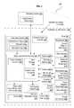
- FIG. 3is a schematic block diagram of a medical support system.
- FIG. 4is an illustration of the medical equipment case of FIG. 2 with medical equipment and two-way audio-visual system removed.
- FIG. 5is an illustration of medical support system including a medical equipment case and a two-way audio-visual system, where the two-way audio-visual system is in a transport position.
- FIG. 6is an illustration of medical support system of FIG. 5 , with the two-way audio-visual system in a use position.
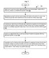
- FIG. 7is a flow diagram of a method of controlling a medical support system.
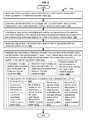
- FIG. 8is a flow diagram of a method of controlling a medical support system.
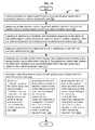
- FIG. 9is a flow diagram of a method of controlling a medical support system.
- FIG. 10is a flow diagram of a method of controlling a medical support system.
- FIG. 11is a flow diagram of a method of controlling a medical support system.
- FIG. 12is a flow diagram of a method of controlling a medical support system.
- FIG. 13is a flow diagram of a method of controlling a medical support system.
- FIG. 1depicts a medical equipment case 100 for transporting at least one article of medical equipment.
- medical equipment case 100is used by a user (e.g. a medical patient) who requires medical monitoring, but is sufficiently healthy to stay at home. For example, if a patient has been discharged from the hospital but requires further medical monitoring until completely recovered, the patient is discharged from the hospital with medical equipment in medical equipment case 100 .
- the medical equipment caseis designed for use in connection with systems in which information is communicated between the medical equipment case and/or equipment stored therein and a central location such as a hospital, for example.
- medical equipment case 100includes a number of security features designed to protect the contents of medical equipment case 100 , including protecting the medical equipment contained therein as well as protecting the privacy/security of patient information or data which may be stored therein.
- medical equipment case 100includes a shell 102 , with at least one cover 104 (depicted in a closed configuration in FIG. 1 ).
- shell 102is sized and configured for transport by a human.
- shell 102can take the form of a suitcase-style luggage container.
- medical equipment case 100includes a handle 106 .
- medical equipment case 100can include one or more fixed handles, extendable handles, wheels, straps, etc. to facilitate transport.
- Medical equipment case 100includes at least one electrically controllable lock mechanism 108 .
- medical equipment case 100also includes user input device 110 , a notification system 112 for providing a notification to a user, and machine-readable indicia 114 .
- machine-readable indicia 114is accessible from outside case 100 when cover 104 is in a closed configuration, and encodes information for return of case 100 from a usage location to a return location.
- a usage locationmay be, for example, the patient's home, and the return location may be a hospital or other medical care facility, or medical equipment supply business, from which medical equipment case 100 and the medical equipment contained therein were obtained (e.g., through loan or rental).
- the user of the medical equipment casemay be the patient, or may be a family member or other caregiver, a medical care provider (e.g.
- Medical equipment case 100can be provided by, communicate with, and/or be controlled by a clinic, hospital, medical care provider, insurance company, or other organization or service provider, for example. Medical equipment case 100 can be provided to a user by loan or rental, for example.
- FIG. 2depicts medical equipment case 100 of FIG. 1 in an open configuration. Components 108 a and 108 b together form controllable lock mechanism 108 as depicted in FIG. 1 .
- Medical equipment case 100includes a first receptacle 200 and second receptacle 202 within the shell 102 .
- First receptacle 200is sized and shaped to receive at least one article of medical equipment 204 .
- Second receptacle 202is sized and shaped to receive a two-way audio-visual system 206 .
- Cover 104is adapted to allow access to the at least one article of medical equipment 204 received within first receptacle 200 when in an open configuration (as depicted in FIG.
- Medical equipment case 100also includes electrical control circuitry 210 , which is located within shell 102 and configured for communication with at least one article of medical equipment 204 and two-way audio-visual system 206 , and communication circuitry 212 , for providing wireless communication between the electrical control circuitry 210 and a remote location 214 .
- remote location 214is a hospital.
- a remote locationcan be a clinic, doctor's office, satellite office, or other location that forms a part of a medical care network.
- Communication between communication circuitry 212 and remote location 214occurs via one or more wireless signal 216 .
- communication circuitry 212provides for wireless communication with a remote location 214 via WiFi, cellular network, or other communication network or technology, including but not limited to satellite communication, microwave radio, broadcast radio, microwave radio, free-space optical link, LAN (Local Area Network), MAN (Metropolitan Area Network), WAN (Wide Area Network), infrared WiFi, and Bluetooth.
- FIG. 3is a generalized block diagram of a system 300 including a medical equipment case 302 .
- Medical equipment casemay include components as described in connection with FIGS. 1 and 2 , including, e.g., shell 304 , cover 306 , at least one receptacle 308 sized and shaped to receive an article of medical equipment 310 , and at least one receptacle 312 sized and shaped to receive at least one two-way audio-visual system 314 .
- Shell 304may be a box-like structure in which cover 306 is a lid, or may take other forms. Cover 306 opens to allow access to at least article of medical equipment 310 received within receptacle 308 .
- the covercan allow access not only to one (and potentially more) articles of medical equipment, but to a two-way audio-visual system and potentially other items contained within the medical equipment case, as well.
- Cover 306can be movably attached to shell 304 , and may pivot, slide, or be lifted away, for example.
- electrically controllable lock mechanism 316is configured to lock cover 306 in a closed configuration.
- medical equipment case 302includes electrical control circuitry 318 and communication circuitry 320 .
- a medical support systemcan be sent home with a patient who has been discharged from the hospital but would benefit from further medical monitoring.
- Medical equipment case 302can contain one or multiple articles of medical equipment 310 .
- Articles of medical equipmentinclude, but are not limited to, devices for sensing, measuring, collecting samples, and/or delivering treatments, for example.
- a single medical devicemay perform one or several such functions.
- an article of medical equipmentincludes, for example, a blood pressure cuff or other blood pressure sensor, stethoscope, bioelectromagnetic monitoring device (including a device for sensing EKG, EEG, EMG, EOG, and magnetic and/or electromagnetic correlates thereof, by contact or non-contact methods), bioelectromagnetic stimulation device (including a device for electrical, magnetic and/or electromagnetic stimulation of nerve, muscle and other excitable tissues, defibrillator, TENS unit, etc.), endoscopic device (e.g., a capsule endoscope), cardiac monitoring device (e.g., heart monitor, heart rate monitor, EKG, Holter monitor, etc.), pulse oximeter, touch probe, thermometer, chemical sensor, biosensor, ultrasound probe, blood
- a chemical sensorcan sense chemical(s) in fluid (gas or liquid) or solid/semi-solid samples, for example body fluid, blood, urine, feces, mucous, saliva, sweat, tears, or inspired/expired gas.
- Sensed chemicalsmay include, but are not limited to, hydrogen ions (pH), glucose, oxygen or carbon dioxide, hormones, proteins, etc.
- Biosensorsmay be used to sense biomolecules, cells, cellular components, and other biological materials or structures, for example, using chemical, immunochemical, and other technologies.
- Sensed parametersinclude but are not limited to temperature, pressure, force, electrical or magnetic field, electrical parameters (e.g.
- an article of medical equipmentincludes an imaging device, for example an ultrasonic, acoustic, electromagnetic, optical, visual, x-ray, or other imaging device.
- devices for delivering treatmentsinclude, but are not limited to drug delivery devices, e.g. a pre-stocked pill container, auto needle-based injector, or infusion system. Usage of such devices can be controlled remotely or locally.
- a drug delivery deviceis selectively unlocked based on a time schedule or control signal from remote location 324 . Usage of a drug delivery device by a user can be confirmed and reported to remote location 324 .
- Receptacle 308 of medical equipment case 302can include power adapter/recharger 326 for supplying power to article of medical equipment 310 during use and/or recharging a battery in article of medical equipment 310 between uses, and data adaptor 328 for transfer of data/instructions between article of medical equipment 310 and electrical control circuitry 318 in medical equipment case 302 .
- Medical support system 322can display prompts to user via notification system 330 or via two-way audio-visual system 314 , to inform user that it is time to make a measurement.
- Notification system 330may include one or more audio, visual, tactile, or other types of display device capable of communicating information to a user of the system.
- Notification system 330may include components that are detectible when medical equipment case 302 is closed, when it is open, or both.
- Notification system 330may include a speaker driven by a sound card to generate an alarm/notification sound or play a pre-recorded or synthesized voice message, or an electrically controlled beeper, buzzer, or bell, for example; one or more lights (e.g.
- a light emitting diodessegmented or pixelated electronic visual display (e.g., liquid crystal, electrophoretic, electroluminescent, electrochromic, photoluminescent, or electromechnical); a refreshable Braille display, or a haptic interface (based on vibratory motors, electroactive polymers, piezoelectric, electrostatic and subsonic audio wave surface actuation, audio haptics, electrostatic haptics, or electric fields, for example).
- a haptic interfacebased on vibratory motors, electroactive polymers, piezoelectric, electrostatic and subsonic audio wave surface actuation, audio haptics, electrostatic haptics, or electric fields, for example).
- Receptacle 312can include a power adaptor/recharger 332 for supplying power to two-way audio-visual system 314 during use and/or recharging a battery in two-way audio-visual system 314 between uses.
- Receptacle 312can include a data adaptor 334 to provide for transfer of data and/or instructions between audio-visual system 314 and electrical control circuitry 318 /audio-visual controller 336 .
- medical equipment caseincludes a shell 304 sized and configured for transport by a human; a first receptacle 308 within shell 304 sized and shaped to receive at least one article of medical equipment 310 ; a second receptacle 312 within shell 304 sized and shaped to receive a two-way audio-visual system 314 ; at least one cover 306 adapted to allow access to the at least one article of medical equipment 310 received within the first receptacle 308 when in an open configuration and to enclose and protect the at least one article of medical equipment 310 received within first receptacle 308 when in a closed configuration; electrical control circuitry 318 located within shell 304 and configured for communication with the at least one article of medical equipment 310 and the two-way audio-visual system 314 ; communication circuitry 320 for providing communication between electrical control circuitry 318 and remote location 324 ; and machine-readable indicia 370 accessible from outside case 302 when cover 306 is in a closed configuration, the machine-readable in
- Machine-readable indicia 370may include, for example, a bar code (including linear or two-dimensional bar codes, e.g. a QR code), data tag, (radio frequency identification) RFID, magnetic strip, or various other types of optically, electrically or magnetically detectable code or text.
- Machine-readable indiciamay provide information regarding a return address to which the medical equipment case is to be shipped when the user is done with using it; the address at which the medical equipment case contents are to be used; the contents of the medical equipment case; an identity of one or more owner or user of the medical equipment case, or an identification code associated therewith; pre-paid pickup and delivery arrangements for a shipping service (e.g. UPS or FedEx); etc.
- Machine-readable indiciamay be printed, embossed, or otherwise formed directly on the medical equipment case or applied as an adhesive label or attached to the case in some other manner, for example.
- medical equipment case 302includes power source 338 mounted within shell 304 and configured to supply power to at least one of article of medical equipment 310 , two-way audio-visual system 314 , electrical control circuitry 318 , and communication circuitry 320 .
- Power source 338may be a battery, solar cell, fuel cell, or energy harvesting device, for example.
- medical equipment case 302can be provided with a power connection 340 for plugging the medical equipment case 302 into a wall outlet or other power source to supply power to some or all components within the case.
- Two-way audio-visual system 314may be mounted in the receptacle 312 , either permanently or temporary. In some cases the two-way audio-visual system 314 is mounted in such a manner that it can be removed prior to use.
- Two-way audio-visual system 314may include, for example, one or more camera, video display, microphone, or speaker.
- Two-way audio-visual system 314may take the form of an off-the-shelf commercially available device that provides two-way audio-visual capability (e.g., a smart phone or tablet computer), or may be assembled from system components as known to those skilled in the art. In an aspect, two-way audio-visual system 314 is a hand-held device.
- Two-way audio-visual system 314may include or be used in combination with an illumination source 366 , which may be a component of two-way audio-visual system 314 , a component of article of medical equipment 310 , a component of medical equipment case 302 , or a separate illumination source.
- illumination source 366is controllable by electrical control circuitry 318 .
- illumination source 366is a component of medical support system 322 .
- two-way audio-visual system 314is configured to be removed from receptacle 312 and placed on a mounting or stand 342 connected to medical equipment case 302 , on the interior or exterior of the medical equipment case 302 .
- mounting or stand 342is pre-attached to one or both of two-way audio-visual system 314 and medical equipment case 302 .
- a mounting or stand 342 connected to medical equipment case 302can be extendable and/or include mechanical linkages, hinges, ball joints, etc. that can be adjusted to permit the position of the two-way audio-visual system to be controlled manually by the user or in automated fashion by a remote operator or by a local or remote control system.
- Control of the position of two-way audio-visual system 314can be controlled audio-visual controller 336 .
- Audio-visual controller 336may also control other aspects of operation of two-way audio-visual system 314 , including pan, tilt, zoom, recording of audio-visual information, presentation of audio-visual information, etc.
- two-way audio-visual system 314is configured to be placed on a mounting or stand that is separate from medical equipment case, or to be placed on any available surface (e.g. a table, a lap of a user, etc.).
- two-way audio-visual system 314is fixedly mounted in the second receptacle, during manufacture or system configuration, so that it is typically removable only when the system is repaired or serviced, or not at all. Mounting of the two-way audio-visual system may be done with a pressure or friction fit, clamps, latches, straps, elastic, screws, rivets, etc., as is known in the art. In an aspect, two-way audio-visual system is movably mounted in the second receptacle, and wherein the two-way audio-visual system is movable between a transport position and a use position, as will be described below in connection with FIGS. 5 and 6 .
- electrical control circuitry 318is mounted within shell 304 .
- electrical control circuitrymay be packaged as a unit that is mounted in the shell but is removable from the shell (e.g., as part of a computing device mounted in a receptacle in the shell), or it may be installed within the shell such that it is not readily accessible by the user, though it may be accessible for repair, maintenance, or reconfiguration.
- electrical control circuitry 318is connected to or incorporated with two-way audio-visual system 314 or with an article of medical equipment 310 .
- electrical control circuitry 318is configured for wireless communication with at least one of the article of medical equipment 310 and the audio-visual system 314 , e.g. via communication circuitry 320 in FIG. 3 .
- Communication between electrical control circuitry 318 and remote location 324 , via communication circuitry 320can be via a wireless communication link (e.g. 4G, WiFi, and various communication technologies described elsewhere herein, e.g. in connection with communication circuitry 212 ).
- Electrical control circuitry 318 and/or communication circuitry 320can be preconfigured for communication with remote location 324 such that when the system is turned on by the user it automatically establishes a connection with the remote location, without instruction by the user.
- Communication between electrical control circuitry 318 and article of medical equipment 310 and two-way audio-visual system 314can be via wired connection, or via a wireless connection, e.g. radiofrequency or other electromagnetic signal, infrared or other optical signal, using communication technologies such as BlueTooth, ZigBee, local area network (LAN), wireless local area network (WLAN), Body Area Network (BAN), cellular network, or WiFi.
- electrical control circuitry 318can be configured for either wired or wireless communication in a switchable manner (e.g. through the use of software and/or switchable hardware).
- electrical control circuitry 318can be configured for only wired or only wireless communication.
- medical equipment case 302controls access to its contents (e.g., article of medical equipment 310 and/or two-way audio-visual system 314 ) such that they are not readily accessible to unauthorized parties. For example, controlling access may prevent loss or theft of valuable medical equipment, unauthorized access to patient medical data, or improper use of equipment. Controlling access may also facilitate communication of data and instructions between the authorized user of the medical equipment and personnel at a remote location. Medical equipment case 302 may be openable only by a specific, authorized person (or by a person in possession of authorization information such as a password).
- medical equipment case 302may be openable only in a specific location, as determined by a global positioning system (GPS) or other localization system.
- GPSglobal positioning system
- a location stored in a memory on the equipment casee.g. data storage 344 in electrical circuitry 318
- a remote location 324it is possible to control access to the contents of medical equipment case 302 to permit the case to be opened only when it is at the home of the user, for example.
- medical equipment case 302includes at least one electrically controllable lock mechanism 316 configured to lock the cover in the closed configuration.
- electrical control circuitry 318is configured to control electrically controllable lock mechanism 316 responsive to receipt of an authorization signal 346 from the remote location 324 by the communication circuitry 320 .
- medical equipment case 302may include a key lock or a combination lock.
- medical equipment caseincludes a position sensing system 348 in communication with the electrical control circuitry 318 .
- electrical control circuitry 318is configured to control the at least one electrically controllable lock mechanism 316 responsive to receipt of a signal from the position sensing system 348 indicative of the medical equipment case being in an authorized location.
- Position sensing system 348may be a global positioning system (GPS) or other localization system for example.
- GPSglobal positioning system
- medical equipment case 302includes user input device 350 mounted on an exterior portion of shell 304 .
- electrical control circuitry 318is configured to control electrically controllable lock mechanism 316 responsive to receipt of an authorization signal 352 from a user via the user input device 350 .
- user input device 350may be adapted to receive a password 354 from the user (for example, user input device 350 may be a keyboard, keypad, other touch sensitive or touch operated device, or a voice interface adapted for entry of an alphanumeric sequence representing a password, which may include, but is not limited to, an identity or access code).
- user input device 350is a digital data reader, which may be, for example, a bar code reader, magnetic strip reader, data tag reader, RFID reader, near field communication (NFC) device or the like, adapted to read a stored password, identity or access code from a linear or two-dimensional bar code, magnetic strip, data tag, RFID, NFC device or chip or the like.
- user input device 350may be adapted to receive a biometric input 356 indicative of user identification from the user (for example, a voice signal for voice pattern recognition, image or other data signal for fingerprint recognition, retinal vascularization recognition, facial recognition, or other types of biometric identification signals).
- medical equipment case 302includes at least one sensor 358 for sensing whether the at least one article of medical equipment 310 is present in the first receptacle 308 .
- Medical equipment case 302includes at least one notification system 330 to provide a notification to a user responsive to sensing that the at least one article of medical equipment 310 is not present in the first receptacle.
- medical equipment case 302also include at least one sensor 360 for sensing whether the two-way audio-visual system 314 is present in the second receptacle 312 .
- medical equipment case 302can include at least one notification system 330 that is configured to provide a notification to a user responsive to sensing that the two-way audio-visual system 314 is not present in second receptacle 312 .
- medical equipment case 302includes a proximity sensor 362 for determining proximity of the at least one article of medical equipment 310 to medical equipment case 302 .
- Proximity sensor 362may be a wireless proximity sensor, for example.
- a proximity sensormay be, for example, an infrared sensor, an optical sensor, an electromagnetic sensor, an acoustic sensor, or any other type of sensor suitable for detecting the proximity of the article of medical equipment to the medical equipment case 302 .
- proximitycan be determined based on the strength of a signal transmitted from the medical equipment case 302 to the article of medical equipment 310 , or vice versa.
- the proximity of the article of medical equipment to the medical equipment casecan be determined based on the strength of a signal transmitted from the medical equipment case, reflected from the article of medical equipment, and detected by proximity sensor 362 .
- medical equipment case 302includes at least one notification system 330 configured to provide a notification to a user responsive to sensing that the at least one article of medical equipment 310 is not in proximity to the medical equipment case 302 .
- medical equipment case 302includes proximity sensor 364 for determining proximity of two-way audio-visual system 314 to medical equipment case 302 .
- Proximity sensor 364may be a wireless proximity sensor, or other type of proximity sensor as discussed herein above with regard to proximity sensor 362 .
- medical equipment case 302includes at least one notification system 330 configured to provide a notification to a user responsive to sensing that the two-way audio-visual system 314 is not in proximity to medical equipment case 302 .
- the notification systemmay provide an audible notification (e.g., generate a beep or squeal, or play a recorded or synthesized voice message) or visible notification (e.g. a flashing light, a text display, etc.) or other detectable notification signal to notify the user that the medical device or two-way audio-visual system is not contained in or in proximity to the medical equipment case.
- audible notificatione.g., generate a beep or squeal, or play a recorded or synthesized voice message
- visible notificatione.g. a flashing light, a text display, etc.
- a voice or text messagemay instruct the user to replace the medical device or two-way audio-visual system in the medical equipment case.
- the casemay be controlled such that it cannot be locked and/or returned until the medical equipment and/or two-way audio-visual system has been returned to the medical equipment case.
- FIG. 4depicts a system generally as depicted in FIGS. 1 and 2 , with the article of medical equipment 204 and two-way audio-visual system 206 removed from medical equipment case 400 for use.
- data, instructions, and other informationare transmitted between article of medical equipment 204 and electrical control circuitry 210 via wireless link 402 , and between two-way audio-visual system 206 and electrical control circuitry 210 via wireless link 404 .
- medical equipment case 400includes shell 102 , cover 104 , handle 106 , electrically controllable lock mechanism including components 108 a and 108 b , user input device 110 , notification system 112 , and machine-readable indicia 114 .
- Two-way audio-visual system 206is configured to be removed from receptacle 202 and placed on a mounting or stand 406 connected to medical equipment case 400 (here shown in the interior of the medical equipment case 402 ; alternatively, mounting or stand 406 could be located on the exterior of the medical equipment case).
- Mounting or stand 406 connected to medical equipment case 400is depicted as including mechanical linkages joined by hinges and/or ball joints to allow for the position of the two-way audio-visual system to be adjusted.
- Medical equipment case 400also includes illumination source 408 on mounting or stand 410 , which provides for adjustable positioning and aiming of illumination source 408 .
- mounting or stand 406 and mounting or stand 410can be folded into medical equipment case 400 when not in use.
- receptacle 200includes sensor 412 for detecting whether article of medical equipment 204 is present in receptacle 200 .
- Medical equipment case 400includes notification system 112 (for example, a light configured to flash, and or a small speaker configured to beep under control of electrical control circuitry 210 ) to provide a notification to a user responsive to sensing that the at least one article of medical equipment 204 is not present in the first receptacle 200 .
- sensor 400is an electrical, optical, magnetic, electromagnetic, or electro-mechanical sensor, for example.
- Medical equipment case 400also includes at least one sensor 414 for sensing whether the two-way audio-visual system 206 is present in the second receptacle 202 .
- medical equipment case 100can include at least one notification system (e.g. notification system 112 ) that is configured to provide a notification to a user responsive to sensing that the two-way audio-visual system 206 is not present in second receptacle 202 .
- a common notification systemcan be used to provide notification to a user regarding presence of medical equipment 204 and two-way audio-visual system 206 , as depicted in FIG. 4 , or, separate notification systems can be used (e.g., separate LEDs that are illuminated to provide notification regarding the two-way audio-visual system and each of one or more articles of medical equipment, respectively).
- FIGS. 5 and 6depict a medical equipment case 500 , which together with two-way audio-visual system 502 and article of medical equipment 504 comprise medical support system 506 .
- Two-way audio-visual system 502is movably mounted in medical equipment case 500 , by means of hinge 508 .
- FIG. 5shows two-way audio-visual system 502 folded down into a transport position such that case 500 can be closed for transport
- FIG. 6shows two-way audio-visual system 502 folded up into a use position.
- a movable mountinge.g. hinge 508 in FIGS. 5 and 6 , or mounting or stand 406 in FIG.
- a movable mountingmay provide for the two-way audio-visual system to be moved by rotation and/or translation in one or more dimensions.
- a movable mountingmay include one or more hinge, sliding mount, ball joint, linkage, and so forth, without limitation.
- medical support system 506which includes medical equipment case 500 , one or more article of medical equipment 504 , and two-way audio-visual system 502 , includes illumination sources 510 and 512 .
- illumination sources 510 and 512are controllable by electrical control circuitry 514 .
- illumination sources 510 and 512are components of two-way audio-visual system 502 . In other aspects, only a single illumination source or a larger number of illumination sources may be used.
- electrical circuitry having at least one discrete electrical circuitincludes electrical circuitry having at least one discrete electrical circuit, electrical circuitry having at least one integrated circuit, electrical circuitry having at least one application specific integrated circuit, electrical circuitry forming a general purpose computing device configured by a computer program (e.g., a general purpose computer configured by a computer program which at least partially carries out processes and/or devices described herein, or a microprocessor configured by a computer program which at least partially carries out processes and/or devices described herein), electrical circuitry forming a memory device (e.g., forms of memory (e.g., random access, flash, read only, etc.)), electrical circuitry forming a communications device (e.g., a modem, communications switch, optical-electrical equipment, etc), and/or any non-electrical analog thereto, such as optical or other analogs (e.g., graphene based circuitry).
- a computer programe.g., a general purpose computer configured by a computer program which at least partially carries out
- a data processing systemgenerally includes one or more of a system unit housing, a video display, memory such as volatile or non-volatile memory, processors such as microprocessors or digital signal processors, computational entities such as operating systems, drivers, graphical user interfaces, and applications programs, one or more interaction devices (e.g., a touch pad, a touch screen, an antenna, etc.), and/or control systems including feedback loops and control motors (e.g., feedback for sensing position and/or velocity; control motors for moving and/or adjusting components and/or quantities).
- a data processing systemmay be implemented utilizing suitable commercially available components, such as those typically found in data computing/communication and/or network computing/communication systems.
- FIG. 7depicts a method of controlling a medical support system.
- Method 700includes receiving at least one status signal indicative of an authorization status with a receiving means in a medical equipment case, at 702 ; generating an electrical lock control signal with electrical control circuitry in the medical equipment case responsive to the at least one status signal, at 704 ; unlocking an electrically controllable lock mechanism responsive to the electrical lock control signal to allow access to at least one article of medical equipment within the medical equipment case responsive to the electrical lock control signal, at 706 ; receiving a signal from the at least one article of medical equipment with the electrical control circuitry, at 708 ; and wirelessly communicating information between the electrical control circuitry and a remote location via communication circuitry in the medical equipment case, wherein the information includes audio-visual information from a two-way audio-visual system in the medical equipment case, at 710 .
- FIGS. 8-13depict variations and expansions of method 700 as shown in FIG. 7 .
- steps 702 - 710are as described generally in connection with FIG. 7 .
- Method steps outlined with dashed linesrepresent steps that are included in some, but not all method aspects, and combinations of steps other than those specifically depicted in the figures are possible as would be known by those having ordinary skill in the relevant art.
- FIG. 8depicts a method 800 , which is an expansion of method 700 shown in FIG. 7 .
- the informationincludes medical data acquired with the at least one article of medical equipment, as indicated at 802 .
- the informationincludes at least one instruction for controlling the at least one article of medical equipment, as indicated at 804 .
- at least a portion of the informationis indicative of an identity of a user of the medical support system, as indicated at 806 .
- at least a portion of the informationis indicative of an operational status of the medical support system, as indicated at 808 .
- the at least a portion of the informationmay be indicative of an unactivated operational status of the medical support system, as indicated at 810 , an activated operational status of the medical support system, as indicated at 812 , a completion-of-use operational status of the medical support system, as indicated at 814 , or a malfunctioning operational status of the medical support system, as indicated at 816 .
- FIG. 9depicts a method 900 , including expansions of step 702 relating to the status signal indicative of an authorization status with a receiving means in the medical equipment case.
- the at least one status signalis a signal from a position sensing system
- generating the electrical lock control signal responsive to the at least one status signalincludes generating the electrical lock control signal to cause unlocking of the electrically controllable lock mechanism responsive to receiving a signal from the position sensing system indicative of the medical equipment case being in an authorized location, as indicated at 902 .
- an authorized locationmay be the home of the patient, another location frequented by the patient (e.g., the home of a friend or relative, a medical clinic, etc.).
- the at least one status signalis an authorization signal from a remote location
- generating the electrical lock control signal responsive to the at least one status signalincludes generating the electrical lock control signal to cause unlocking of the electrically controllable lock mechanism responsive to receiving an authorization signal from a remote location, as indicated at 904 .
- the at least one status signalis a user-generated signal from a user input device, and generating the electrical lock control signal responsive to the at least one status signal includes generating the electrical lock control signal to cause unlocking of the electrically controllable lock mechanism responsive to receiving a user-generated signal indicative of the medical equipment case being used by an authorized user, as indicated at 906 .
- the at least one status signalmay be a biometric input indicative of user identity, indicated at 908 , or a password, as indicated at 910 .
- FIG. 10depicts a method 1000 , which includes steps 702 , 704 , 706 , 708 , and 710 as described in connection with FIG. 7 .
- method 1000includes detecting whether the at least one article of medical equipment is located within the medical equipment case, as indicated at 1002 .
- method 1000also includes activating a notification system in the medical equipment case to provide a notification to a user responsive to sensing that the at least one article of medical equipment is not located within the medical equipment case, as indicated at 1004 , generating the electrical lock control signal with the electrical control circuitry in the medical equipment case to cause locking of the electrically controllable lock mechanism responsive to sensing that the at least one article of medical equipment is located within the medical equipment case, as indicated at 1006 , or generating the electrical lock control signal with the electrical control circuitry in the medical equipment case to prevent locking of the electrically controllable lock mechanism responsive to sensing that the at least one article of medical equipment is not located within the medical equipment case, as indicated at 1008 .
- the casewill be permitted to lock so that the user can return it to the hospital or other return location, whereas if the user has failed to return the article of medical equipment to the medical equipment case, the user will not be able to lock the case in and return it to the hospital or other return location until the equipment has been return to the case.
- the risk of the medical equipment case being returned to with one or more article of medical equipment missingis reduced.
- FIG. 11depicts a method 1100 , which includes steps 702 , 704 , 706 , 708 , and 710 as described in connection with FIG. 7 , and which also includes detecting whether the two-way audio-visual system is located within the medical equipment case, as indicated at 1102 .
- method 1100also includes activating a notification system in the medical equipment case to provide a notification to a user responsive to sensing that the two-way audio-visual system is not located within the medical equipment case, as indicated at 1104 , generating the electrical lock control signal with the electrical control circuitry in the medical equipment case to cause locking of the electrically controllable lock mechanism responsive to sensing that the two-way audio-visual system is located within the medical equipment case, as indicated at 1106 , or generating the electrical lock control signal with the electrical control circuitry in the medical equipment case to prevent locking of the electrically controllable lock mechanism responsive to sensing that the two-way audio-visual system is not located within the medical equipment case, as indicated at 1108 .
- the casewill be permitted to lock so that the user can return it to the hospital or other return location, whereas if the user has failed to return the two-way audio-visual system to the medical equipment case, the user will not be able to lock the case in and return it to the hospital or other return location until the equipment has been return to the case. Thus, the risk of the medical equipment case being returned to without two-way audio-visual system is reduced.
- FIG. 12depicts a method 1200 , which includes steps 702 , 704 , 706 , 708 , and 710 as described in connection with FIG. 7 , and which also includes sensing proximity of the at least one article of medical equipment to the medical equipment case, as indicated at 1202 .
- method 1200includes activating a notification system in the medical equipment case to provide a notification to a user responsive to sensing that the at least one article of medical equipment is not within a specified proximity to the medical equipment case, as indicated at 1204 , generating the electrical lock control signal with the electrical control circuitry in the medical equipment case to cause locking of the electrically controllable lock mechanism responsive to sensing that the at least one article of medical equipment is within a specified proximity to the medical equipment case, as indicated at 1206 , or generating the electrical lock control signal with the electrical control circuitry in the medical equipment case to prevent locking of the electrically controllable lock mechanism responsive to sensing that the at least one article of medical equipment is not within a specified proximity to the medical equipment case, as indicated at 1208 .
- FIG. 13depicts a method 1300 , which includes steps 702 , 704 , 706 , 708 , and 710 as described in connection with FIG. 7 , and which also includes sensing proximity of the two-way audio-visual system to the medical equipment case, as indicated at 1302 .
- method 1300also includes activating a notification system in the medical equipment case to provide a notification to a user responsive to sensing that the two-way audio-visual system is not within a specified proximity to the medical equipment case, as indicated at 1304 , generating the electrical lock control signal with the electrical control circuitry in the medical equipment case to cause locking of the electrically controllable lock mechanism responsive to sensing that the two-way audio-visual system is within a specified proximity to the medical equipment case, as indicated at 1306 , or generating the electrical lock control signal with the electrical control circuitry in the medical equipment case to prevent locking of the electrically controllable lock mechanism responsive to sensing that the two-way audio-visual system is not within a specified proximity to the medical equipment case, as indicated at 1308 .
- methods as described hereinmay be performed according to instructions implementable in hardware, software, and/or firmware. Such instructions may be stored in non-transitory machine-readable data storage media, for example.
- Such instructionsmay be stored in non-transitory machine-readable data storage media, for example.
- logic and similar implementationsmay include software or other control structures.
- Electrical circuitrymay have one or more paths of electrical current constructed and arranged to implement various functions as described herein.
- one or more mediamay be configured to bear a device-detectable implementation when such media hold or transmit device detectable instructions operable to perform as described herein.
- implementationsmay include an update or modification of existing software or firmware, or of gate arrays or programmable hardware, such as by performing a reception of or a transmission of one or more instructions in relation to one or more operations described herein.
- an implementationmay include special-purpose hardware, software, firmware components, and/or general-purpose components executing or otherwise invoking special-purpose components.
- Implementationsmay include executing a special-purpose instruction sequence or invoking circuitry for enabling, triggering, coordinating, requesting, or otherwise causing one or more occurrences of virtually any functional operations described herein.
- operational or other logical descriptions hereinmay be expressed as source code and compiled or otherwise invoked as an executable instruction sequence.
- implementationsmay be provided, in whole or in part, by source code, such as C++, or other code sequences.
- source or other code implementationmay be compiled//implemented/translated/converted into a high-level descriptor language (e.g., initially implementing described technologies in C or C++ programming language and thereafter converting the programming language implementation into a logic-synthesizable language implementation, a hardware description language implementation, a hardware design simulation implementation, and/or other such similar mode(s) of expression).
- a high-level descriptor languagee.g., initially implementing described technologies in C or C++ programming language and thereafter converting the programming language implementation into a logic-synthesizable language implementation, a hardware description language implementation, a hardware design simulation implementation, and/or other such similar mode(s) of expression.
- a logical expressione.g., computer programming language implementation
- a Verilog-type hardware descriptione.g., via Hardware Description Language (HDL) and/or Very High Speed Integrated Circuit Hardware Descriptor Language (VHDL)
- VHDLVery High Speed Integrated Circuit Hardware Descriptor Language
- Those skilled in the artwill recognize how to obtain, configure, and optimize suitable transmission or computational elements, material supplies, actuators, or other structures in light of these teachings.
- a signal bearing mediuminclude, but are not limited to non-transitory machine-readable data storage media such as a recordable type medium such as a floppy disk, a hard disk drive, a Compact Disc (CD), a Digital Video Disk (DVD), a digital tape, a computer memory, etc.
- a signal bearing mediummay also include transmission type medium such as a digital and/or an analog communication medium (e.g., a fiber optic cable, a waveguide, a wired communications link, a wireless communication link (e.g., transmitter, receiver, transmission logic, reception logic, etc) and so forth).
- transmission type mediumsuch as a digital and/or an analog communication medium (e.g., a fiber optic cable, a waveguide, a wired communications link, a wireless communication link (e.g., transmitter, receiver, transmission logic, reception logic, etc) and so forth).
- any two components so associatedcan also be viewed as being “operably connected”, or “operably coupled,” to each other to achieve the desired functionality, and any two components capable of being so associated can also be viewed as being “operably couplable,” to each other to achieve the desired functionality.
- operably couplableinclude but are not limited to physically mateable and/or physically interacting components, and/or wirelessly interactable, and/or wirelessly interacting components, and/or logically interacting, and/or logically interactable components.
- one or more componentsmay be referred to herein as “configured to,” “configured by,” “configurable to,” “operable/operative to,” “adapted/adaptable,” “able to,” “conformable/conformed to,” etc.
- configured togenerally encompass active-state components and/or inactive-state components and/or standby-state components, unless context requires otherwise.
Landscapes
- Engineering & Computer Science (AREA)
- Health & Medical Sciences (AREA)
- Biomedical Technology (AREA)
- General Business, Economics & Management (AREA)
- Business, Economics & Management (AREA)
- Medical Informatics (AREA)
- General Health & Medical Sciences (AREA)
- Epidemiology (AREA)
- Primary Health Care (AREA)
- Public Health (AREA)
- Signal Processing (AREA)
- Multimedia (AREA)
- Automation & Control Theory (AREA)
- General Physics & Mathematics (AREA)
- Physics & Mathematics (AREA)
- General Engineering & Computer Science (AREA)
- Measuring And Recording Apparatus For Diagnosis (AREA)
Abstract
Description
Claims (32)
Priority Applications (5)
| Application Number | Priority Date | Filing Date | Title |
|---|---|---|---|
| US13/930,928US9075906B2 (en) | 2013-06-28 | 2013-06-28 | Medical support system including medical equipment case |
| US14/752,138US9846763B2 (en) | 2013-06-28 | 2015-06-26 | Medical support system including medical equipment case |
| US15/830,155US20180160073A1 (en) | 2013-06-28 | 2017-12-04 | Remote monitoring of telemedicine device |
| US15/838,831US10236080B2 (en) | 2013-06-28 | 2017-12-12 | Patient medical support system and related method |
| US16/296,415US10692599B2 (en) | 2013-06-28 | 2019-03-08 | Patient medical support system and related method |
Applications Claiming Priority (1)
| Application Number | Priority Date | Filing Date | Title |
|---|---|---|---|
| US13/930,928US9075906B2 (en) | 2013-06-28 | 2013-06-28 | Medical support system including medical equipment case |
Related Parent Applications (1)
| Application Number | Title | Priority Date | Filing Date |
|---|---|---|---|
| US15/830,155Continuation-In-PartUS20180160073A1 (en) | 2013-06-28 | 2017-12-04 | Remote monitoring of telemedicine device |
Related Child Applications (1)
| Application Number | Title | Priority Date | Filing Date |
|---|---|---|---|
| US14/752,138ContinuationUS9846763B2 (en) | 2013-06-28 | 2015-06-26 | Medical support system including medical equipment case |
Publications (2)
| Publication Number | Publication Date |
|---|---|
| US20150002606A1 US20150002606A1 (en) | 2015-01-01 |
| US9075906B2true US9075906B2 (en) | 2015-07-07 |
Family
ID=52115198
Family Applications (4)
| Application Number | Title | Priority Date | Filing Date |
|---|---|---|---|
| US13/930,928Expired - Fee RelatedUS9075906B2 (en) | 2013-06-28 | 2013-06-28 | Medical support system including medical equipment case |
| US14/752,138Expired - Fee RelatedUS9846763B2 (en) | 2013-06-28 | 2015-06-26 | Medical support system including medical equipment case |
| US15/838,831Expired - Fee RelatedUS10236080B2 (en) | 2013-06-28 | 2017-12-12 | Patient medical support system and related method |
| US16/296,415Expired - Fee RelatedUS10692599B2 (en) | 2013-06-28 | 2019-03-08 | Patient medical support system and related method |
Family Applications After (3)
| Application Number | Title | Priority Date | Filing Date |
|---|---|---|---|
| US14/752,138Expired - Fee RelatedUS9846763B2 (en) | 2013-06-28 | 2015-06-26 | Medical support system including medical equipment case |
| US15/838,831Expired - Fee RelatedUS10236080B2 (en) | 2013-06-28 | 2017-12-12 | Patient medical support system and related method |
| US16/296,415Expired - Fee RelatedUS10692599B2 (en) | 2013-06-28 | 2019-03-08 | Patient medical support system and related method |
Country Status (1)
| Country | Link |
|---|---|
| US (4) | US9075906B2 (en) |
Cited By (3)
| Publication number | Priority date | Publication date | Assignee | Title |
|---|---|---|---|---|
| US10236080B2 (en)* | 2013-06-28 | 2019-03-19 | Elwha Llc | Patient medical support system and related method |
| US10335045B2 (en) | 2016-06-24 | 2019-07-02 | Universita Degli Studi Di Trento | Self-adaptive matrix completion for heart rate estimation from face videos under realistic conditions |
| US20220045869A1 (en)* | 2018-11-29 | 2022-02-10 | Leica Biosystems Melbourne Pty Ltd | Blockchain-based consumables management with support for offline instruments |
Families Citing this family (30)
| Publication number | Priority date | Publication date | Assignee | Title |
|---|---|---|---|---|
| US20130023741A1 (en)* | 2011-07-20 | 2013-01-24 | Stephen Teni Ayanruoh | Integrated Portable Medical Diagnostic System |
| US9838645B2 (en) | 2013-10-31 | 2017-12-05 | Elwha Llc | Remote monitoring of telemedicine device |
| EP3097245B1 (en) | 2014-01-22 | 2019-10-16 | InVue Security Products, Inc. | Systems and methods for remotely controlling security devices |
| US9572748B2 (en)* | 2014-03-28 | 2017-02-21 | Celico Partnership | Prescription container and service for monitoring patients |
| WO2015175578A1 (en)* | 2014-05-12 | 2015-11-19 | Michael Shen | Directing treatment of cardiovascular events by non-specialty caregivers |
| WO2015191954A1 (en) | 2014-06-12 | 2015-12-17 | Endoluxe Inc. | Encasement platform for smartdevice for attachment to endoscope |
| US10478261B2 (en)* | 2015-05-29 | 2019-11-19 | Deka Products Limited Partnership | System, method, and apparatus for remote patient care |
| DE102016111971A1 (en)* | 2016-06-30 | 2018-01-04 | Fresenius Medical Care Deutschland Gmbh | Dedicated remote control of several dialysis machines |
| US20180039752A1 (en)* | 2016-08-05 | 2018-02-08 | Italo Subbarao | Portable emergency telehealth system and method |
| US20190043615A1 (en)* | 2016-08-05 | 2019-02-07 | Italo Ramachandra Subbarao | Portable emergency telehealth system and method |
| DE102017107513A1 (en) | 2017-04-07 | 2018-10-11 | M.Doc Gmbh | Release of medical modules of a medical equipment |
| US10242557B2 (en)* | 2017-06-20 | 2019-03-26 | Erik Ward | User-responsive medical trauma treatment device |
| WO2019023055A1 (en)* | 2017-07-28 | 2019-01-31 | Lifelens Technologies, Llc | Physiologic monitoring kits |
| IT201700087541A1 (en)* | 2017-07-31 | 2019-01-31 | Cooperativa Samidad Soc Cooperativa Sociale Per Azioni O N L U S | REMOTE ASSISTANCE KIT FOR A PATIENT |
| CN107340831A (en)* | 2017-09-13 | 2017-11-10 | 北京默辰信息科技有限公司 | A kind of Mobile office equipment box based on communication network |
| US10772488B2 (en) | 2017-11-10 | 2020-09-15 | Endoluxe Inc. | System and methods for endoscopic imaging |
| CN110554611A (en)* | 2018-06-04 | 2019-12-10 | 珠海格力电器股份有限公司 | Intelligent household control method and device and intelligent household system |
| US10838050B2 (en) | 2018-06-18 | 2020-11-17 | Fujifilm Sonosite, Inc. | Ultrasound imaging system including wireless probe tracking |
| US10354058B1 (en) | 2018-11-21 | 2019-07-16 | Capital One Services, Llc | Systems and methods for safely storing an object |
| US12014500B2 (en) | 2019-04-14 | 2024-06-18 | Holovisions LLC | Healthy-Selfie(TM): methods for remote medical imaging using a conventional smart phone or augmented reality eyewear |
| US11308618B2 (en) | 2019-04-14 | 2022-04-19 | Holovisions LLC | Healthy-Selfie(TM): a portable phone-moving device for telemedicine imaging using a mobile phone |
| US12434866B2 (en)* | 2020-06-02 | 2025-10-07 | University Of Cincinnati | Care delivery telehealth drone |
| US11394695B2 (en)* | 2020-07-02 | 2022-07-19 | Kpn Innovations, Llc. | Methods and systems for generating a secure communication channel interface for video streaming of sensitive content |
| US11706265B2 (en) | 2021-01-14 | 2023-07-18 | Arris Enterprises Llc | Companion camera and microphone |
| KR20240024856A (en)* | 2021-05-27 | 2024-02-26 | 조지아 테크 리서치 코포레이션 | Wireless soft scalp electronics and virtual reality systems for brain-device interfaces |
| US11657779B2 (en) | 2021-08-03 | 2023-05-23 | Avaya Management L.P. | Transmission of solid color images over a communication session for illumination at an endpoint |
| US12296184B2 (en)* | 2021-09-22 | 2025-05-13 | West Affum Holdings Dac | Providing wearable device information to rescuers |
| US12376731B2 (en) | 2022-01-10 | 2025-08-05 | Endoluxe Inc. | Systems, apparatuses, and methods for endoscopy |
| WO2023150575A2 (en)* | 2022-02-01 | 2023-08-10 | The George Washington University | Cyber-physical system to enhance usability and quality of telehealth consultation |
| CN115240806B (en)* | 2022-07-25 | 2023-03-21 | 南通大学 | High safe type hospital information system inquiry unit |
Citations (53)
| Publication number | Priority date | Publication date | Assignee | Title |
|---|---|---|---|---|
| US4843373A (en)* | 1987-12-10 | 1989-06-27 | Rite-Hite Corporation | Loading dock signal and control system |
| US5014875A (en)* | 1989-03-01 | 1991-05-14 | Pyxis Corporation | Medication dispenser station |
| US5164707A (en)* | 1990-02-28 | 1992-11-17 | Cabot Safety Corporation | Detection system for safety equipment |
| US5694919A (en)* | 1993-01-29 | 1997-12-09 | Aradigm Corporation | Lockout device for controlled release of drug from patient-activated dispenser |
| US6056716A (en) | 1987-06-08 | 2000-05-02 | D'antonio Consultants International Inc. | Hypodermic fluid dispenser |
| US6169707B1 (en)* | 1998-11-30 | 2001-01-02 | Douglas A. Newland | Medication storage and reminder device |
| US6398727B1 (en) | 1998-12-23 | 2002-06-04 | Baxter International Inc. | Method and apparatus for providing patient care |
| DE10240904A1 (en) | 2002-09-04 | 2004-03-11 | Teachscreen Software Gmbh | Device for uniform illumination of object surfaces in close up photography for skin studies, has diffuser and spacer between flash lamp and object |
| US20050060198A1 (en) | 2000-07-06 | 2005-03-17 | Bayne Cary Gresham | Method for clinician house calls utilizing portable computing and communications equipment |
| US6925357B2 (en) | 2002-07-25 | 2005-08-02 | Intouch Health, Inc. | Medical tele-robotic system |
| US20050256392A1 (en) | 2004-05-12 | 2005-11-17 | Yvedt Matory | Systems and methods for remote body imaging evaluation |
| US7044744B2 (en)* | 2003-08-12 | 2006-05-16 | Tyco Electronics Amp Gmbh | Electrical vehicle door handle plug connection system |
| US7158860B2 (en) | 2003-02-24 | 2007-01-02 | Intouch Technologies, Inc. | Healthcare tele-robotic system which allows parallel remote station observation |
| US7161322B2 (en) | 2003-11-18 | 2007-01-09 | Intouch Technologies, Inc. | Robot with a manipulator arm |
| US7171286B2 (en) | 2003-02-24 | 2007-01-30 | Intouch Technologies, Inc. | Healthcare tele-robotic system with a robot that also functions as a remote station |
| US20070055166A1 (en) | 2005-09-02 | 2007-03-08 | Chandrashekhar Patil | Method and system for recording and transmitting data from biometric sensors |
| US7289211B1 (en) | 2004-04-09 | 2007-10-30 | Walsh Jr Joseph T | System and method for imaging sub-surface polarization-sensitive material structures |
| US20080275315A1 (en) | 2004-01-09 | 2008-11-06 | Hiroshi Oka | Pigmentary Deposition Portion Remote Diagnosis System |
| US20080309487A1 (en)* | 2007-06-12 | 2008-12-18 | Trade-Van Information Services Co. | Container monitoring system and an electronic container lock |
| US20090043253A1 (en)* | 2005-10-11 | 2009-02-12 | Blake Podaima | Smart medical compliance method and system |
| US20090093688A1 (en) | 2003-05-30 | 2009-04-09 | Michael Mathur | System, Device, and Method for Remote Monitoring and Servicing |
| US20090154781A1 (en) | 2007-12-14 | 2009-06-18 | Electro-Optical Sciences, Inc. | Characterizing a Texture of an Image |
| US20090182582A1 (en)* | 2008-01-15 | 2009-07-16 | Hawkeye Production Llc | System and portable apparatus for securely dispensing and maintaining accurate inventory of controlled substances in a hospital setting |
| US20090227877A1 (en) | 2006-05-12 | 2009-09-10 | Bao Tran | Health monitoring appliance |
| US20090236954A1 (en)* | 2008-03-24 | 2009-09-24 | Sanyo Electric Co., Ltd. | Medication Storage |
| US20090276090A1 (en)* | 2002-02-22 | 2009-11-05 | Gw Phama Limited | Dose dispensing system and apparatus |
| US20090292552A1 (en) | 2008-05-20 | 2009-11-26 | Chen Jiunn-Rong | Integrated and interactive health-management system |
| US20090301925A1 (en)* | 2006-07-05 | 2009-12-10 | Alloro Michael Cohen | Medication Dispenser |
| US20090306487A1 (en) | 2006-04-11 | 2009-12-10 | The University Of Nottingham | Photoplethysmography |
| US7894651B2 (en) | 2007-03-02 | 2011-02-22 | Mela Sciences, Inc. | Quantitative analysis of skin characteristics |
| US20110064287A1 (en) | 2009-09-14 | 2011-03-17 | Alexandru Bogdan | Characterizing a texture of an image |
| US20110105853A1 (en) | 2009-09-11 | 2011-05-05 | Rakowski Richard R | Systems and methods for healthcare delivery, observation, and communication between a de-centralized healthcare system and a patient living at home |
| US20110144455A1 (en) | 2007-08-31 | 2011-06-16 | Bam Labs, Inc. | Systems and methods for monitoring a subject at rest |
| US8074273B2 (en)* | 2004-11-19 | 2011-12-06 | Kabushiki Kaisha Toshiba | Security management system, medical device and method for managing security |
| US20120041275A1 (en) | 2009-04-22 | 2012-02-16 | Mitaka Kohki Co., Ltd. | Derivation method of discrimination threshold of nail apparatus melanoma |
| US8125549B2 (en) | 2008-09-02 | 2012-02-28 | General Electric Company | Methods and apparatus to capture compressed images |
| US20120095352A1 (en) | 2006-05-16 | 2012-04-19 | Bao Tran | Health monitoring appliance |
| US20120101371A1 (en) | 2010-10-25 | 2012-04-26 | Steven Roger Verdooner | Apparatus and Method For Detecting Amyloid In A Retina in a Diagnosis, Advancement, and Prognosing Of Alzheimer's disease, traumatic brain injury, macular degeneration and a plurality of Neurodegenerative dissorders, and Ocular Diseases |
| US8199244B2 (en) | 2005-04-21 | 2012-06-12 | William Marsh Rice University | Method and apparatus for compressive imaging device |
| US20120157800A1 (en) | 2010-12-17 | 2012-06-21 | Tschen Jaime A | Dermatology imaging device and method |
| US20120197464A1 (en) | 2011-01-28 | 2012-08-02 | Intouch Health | Interfacing with a mobile telepresence robot |
| USD669587S1 (en) | 2010-09-06 | 2012-10-23 | FotoFinder Systems GmbH | External lens for cell phones |
| US20120268462A1 (en) | 2009-12-24 | 2012-10-25 | Mitaka Kohki Co., Ltd. | Method of discriminating longitudinal melanonychia and visualizing malignancy thereof |
| US20120307056A1 (en) | 2011-06-01 | 2012-12-06 | Zuzak Karel J | System and method for hyperspectral imaging |
| US8348885B2 (en) | 2006-04-28 | 2013-01-08 | Medtronic Minimed, Inc. | Remote monitoring for networked fluid infusion systems |
| US20130083185A1 (en) | 2011-09-30 | 2013-04-04 | Intuitive Medical Technologies, Llc | Optical adapter for ophthalmological imaging apparatus |
| US20130128223A1 (en) | 2011-11-09 | 2013-05-23 | Wetch Allyn, Inc. | Digital-based medical devices |
| US8452446B1 (en) | 2012-04-19 | 2013-05-28 | Innovative Dispensing, LLC | Automatic pill dispenser |
| US8544645B2 (en) | 2005-02-01 | 2013-10-01 | Intelliject, Inc. | Devices, systems and methods for medicament delivery |
| US8544646B2 (en)* | 2011-06-06 | 2013-10-01 | King Fahd University Of Petroleum And Minerals | Medical safety box |
| US20130278067A1 (en)* | 2010-07-28 | 2013-10-24 | James Andrew Poss | Electrically-powered programmable waste enclosure |
| US8648269B2 (en)* | 2010-03-17 | 2014-02-11 | Mitsubishi Electric Power Products, Inc. | Keyless solenoid release unit |
| US20150002606A1 (en)* | 2013-06-28 | 2015-01-01 | Elwha Llc | Medical support system including medical equipment case |
Family Cites Families (105)
| Publication number | Priority date | Publication date | Assignee | Title |
|---|---|---|---|---|
| US3974363A (en) | 1973-04-06 | 1976-08-10 | Xerox Corporation | Programmable billing system |
| US4763810A (en)* | 1986-12-19 | 1988-08-16 | Christiansen Lee T | Medication dispenser |
| KR930018124A (en)* | 1992-02-25 | 1993-09-21 | 미다무라 유끼히로 | Safe Deposit Box System |
| US5993046A (en)* | 1993-01-25 | 1999-11-30 | Diebold, Incorporated | System for dispensing medical items by brand or generic name |
| US5790409A (en)* | 1993-01-25 | 1998-08-04 | Medselect Systems, Inc. | Inventory monitoring and dispensing system for medical items |
| US5533079A (en)* | 1993-01-25 | 1996-07-02 | Medselect Systems, Inc. | Inventory monitoring apparatus |
| US6027217A (en)* | 1996-07-31 | 2000-02-22 | Virtual-Eye.Com, Inc. | Automated visual function testing via telemedicine |
| US5987519A (en)* | 1996-09-20 | 1999-11-16 | Georgia Tech Research Corporation | Telemedicine system using voice video and data encapsulation and de-encapsulation for communicating medical information between central monitoring stations and remote patient monitoring stations |
| US6095661A (en) | 1998-03-19 | 2000-08-01 | Ppt Vision, Inc. | Method and apparatus for an L.E.D. flashlight |
| US6007459A (en) | 1998-04-14 | 1999-12-28 | Burgess; Barry | Method and system for providing physical therapy services |
| US7256708B2 (en)* | 1999-06-23 | 2007-08-14 | Visicu, Inc. | Telecommunications network for remote patient monitoring |
| US6577899B2 (en)* | 2000-01-21 | 2003-06-10 | Medtronic Minimed, Inc. | Microprocessor controlled ambulatory medical apparatus with hand held communication device |
| US6450955B1 (en) | 2000-04-28 | 2002-09-17 | International Business Machines Corporation | Monitoring user health as measured by multiple diverse health measurement devices at a portable computer system |
| CA2325205A1 (en)* | 2000-11-02 | 2002-05-02 | The Sullivan Group | Computerized risk management module for medical diagnosis |
| US20020186243A1 (en)* | 2001-06-06 | 2002-12-12 | Robert Ellis | Method and system for providing combined video and physiological data over a communication network for patient monitoring |
| US7865380B2 (en) | 2001-11-08 | 2011-01-04 | International Business Machines Corporation | Automated information technology management system |
| US20030093301A1 (en) | 2001-11-13 | 2003-05-15 | Hypertension Diagnostics, Inc. | Centralized clinical data management system process for analysis and billing |
| ATE445354T1 (en)* | 2001-12-10 | 2009-10-15 | Medic4All Ag | VISUAL MEDICAL MONITORING SYSTEM FOR A REMOTE PERSON |
| US20040070615A1 (en)* | 2002-05-31 | 2004-04-15 | Ewing Richard E. | Communicating medical information in a communication network |
| US8988599B2 (en) | 2010-08-31 | 2015-03-24 | University Of Southern California | Illumination sphere with intelligent LED lighting units in scalable daisy chain with interchangeable filters |
| US10009577B2 (en)* | 2002-08-29 | 2018-06-26 | Comcast Cable Communications, Llc | Communication systems |
| US20040119814A1 (en) | 2002-12-20 | 2004-06-24 | Clisham Allister B. | Video conferencing system and method |
| EP1618736A2 (en) | 2003-01-29 | 2006-01-25 | Everest-VIT, Inc. | Remote video inspection system |
| US20060173355A1 (en) | 2003-04-17 | 2006-08-03 | Alfano Robert R | Detecting human cancer through spectral optical imaging using key water absorption wavelengths |
| KR20060039900A (en)* | 2003-07-16 | 2006-05-09 | 코닌클리케 필립스 일렉트로닉스 엔.브이. | Health care systems arranged to monitor the physiological conditions of portable electronic devices and individuals |
| US20050196023A1 (en)* | 2004-03-01 | 2005-09-08 | Eastman Kodak Company | Method for real-time remote diagnosis of in vivo images |
| US20050285145A1 (en) | 2004-06-23 | 2005-12-29 | Nadarajah Narendran | Web image transfer system using LED based lighting systems |
| US7747491B2 (en) | 2004-11-19 | 2010-06-29 | Panasonic Corporation | Anonymous information system, information registering device and information storing device |
| US9043015B2 (en)* | 2004-12-11 | 2015-05-26 | Nitesh Ratnakar | Smart medicine container assembly |
| US20060173267A1 (en)* | 2004-12-27 | 2006-08-03 | Aprius Medical Service, Inc. | Method and device for administering health care remotely |
| JP5138384B2 (en) | 2005-01-10 | 2013-02-06 | サイトリ セラピューティクス インコーポレイテッド | Apparatus and method for monitoring, managing and servicing medical devices |
| US8206360B2 (en)* | 2005-02-01 | 2012-06-26 | Intelliject, Inc. | Devices, systems and methods for medicament delivery |
| US9198608B2 (en)* | 2005-04-28 | 2015-12-01 | Proteus Digital Health, Inc. | Communication system incorporated in a container |
| US7907164B2 (en) | 2005-05-02 | 2011-03-15 | Lifesize Communications, Inc. | Integrated videoconferencing system |
| JP2009500803A (en) | 2005-07-08 | 2009-01-08 | コーニンクレッカ フィリップス エレクトロニクス エヌ ヴィ | Lighting device for illuminating an object |
| US20110010087A1 (en)* | 2005-10-24 | 2011-01-13 | CellTrak Technologies, Inc. | Home Health Point-of-Care and Administration System |
| EP1968691A4 (en)* | 2005-12-14 | 2012-01-25 | Welch Allyn Inc | WIRELESS ADAPTER FOR MEDICAL DEVICE |
| JP2007181030A (en) | 2005-12-28 | 2007-07-12 | Funai Electric Co Ltd | Image display device |
| US8125508B2 (en) | 2006-01-24 | 2012-02-28 | Lifesize Communications, Inc. | Sharing participant information in a videoconference |
| ATE506811T1 (en)* | 2006-02-06 | 2011-05-15 | Koninkl Philips Electronics Nv | AUDIO-VIDEO SWITCH |
| US7607573B1 (en)* | 2007-01-03 | 2009-10-27 | Diebold, Incorporated | Banking system operated responsive to data bearing records |
| CN101595486A (en)* | 2007-02-02 | 2009-12-02 | 皇家飞利浦电子股份有限公司 | Interactive patient forums |
| WO2009023634A2 (en) | 2007-08-10 | 2009-02-19 | Smiths Medical Md, Inc. | System for controlling medical devices |
| US7933783B2 (en)* | 2007-10-01 | 2011-04-26 | American Well Corporation | Medical listener |
| US10007761B2 (en)* | 2008-03-20 | 2018-06-26 | 3 Net Wise, Inc. | Method and apparatus for sharing medical information |
| US20090318815A1 (en) | 2008-05-23 | 2009-12-24 | Michael Barnes | Systems and methods for hyperspectral medical imaging |
| US8414043B2 (en) | 2008-10-21 | 2013-04-09 | Foster-Miller, Inc. | End effector for mobile remotely controlled robot |
| US8305423B2 (en)* | 2008-11-24 | 2012-11-06 | Innovatec, S.L. | Communication system for remote patient visits and clinical status monitoring |
| US20100217618A1 (en) | 2009-02-25 | 2010-08-26 | Piccirillo Charles J | Event Detection Based on Location Observations and Status Conditions of Healthcare Resources |
| US20100222649A1 (en)* | 2009-03-02 | 2010-09-02 | American Well Systems | Remote medical servicing |
| US20100228825A1 (en)* | 2009-03-06 | 2010-09-09 | Microsoft Corporation | Smart meeting room |
| US20100280350A1 (en)* | 2009-05-02 | 2010-11-04 | Xinyu Zhang | Chinese medicine tele-diagnostics and triage system |
| JP2010275074A (en)* | 2009-05-29 | 2010-12-09 | Casio Computer Co Ltd | Information transmitter |
| WO2011044399A2 (en)* | 2009-10-07 | 2011-04-14 | Mcelveen John T | System for remote monitoring and modulation of medical apparatus |
| US9974485B2 (en)* | 2009-12-11 | 2018-05-22 | Verizon Patent And Licensing Inc. | Method and system for providing remote healthcare services |
| TW201122890A (en)* | 2009-12-18 | 2011-07-01 | Best Solution Technology Inc | Touch-control lock operated according to gesture or figure. |
| US20110184249A1 (en) | 2010-01-27 | 2011-07-28 | Davis Jr Daniel C | Remote patient monitoring system |
| US20110267418A1 (en)* | 2010-04-30 | 2011-11-03 | Alejandro Javier Patron Galindo | Telemedicine system |
| US20110270631A1 (en)* | 2010-05-03 | 2011-11-03 | AMD Global Telemedicine, Inc. | Remote healthcare data-gathering and viewing system and method |
| US20110282168A1 (en)* | 2010-05-14 | 2011-11-17 | Waldo Networks | Health monitoring device and methods thereof |
| US8553067B2 (en)* | 2010-07-01 | 2013-10-08 | Cisco Technology, Inc. | Capturing and controlling access to muted content from a conference session |
| DE102010026478A1 (en)* | 2010-07-07 | 2012-01-12 | Tammo Bialas | System for displaying a medical diagnosis result |
| WO2012015543A2 (en)* | 2010-07-30 | 2012-02-02 | Fawzi Shaya | System, method and apparatus for performing real-time virtual medical examinations |
| WO2012028999A2 (en) | 2010-08-31 | 2012-03-08 | Koninklijke Philips Electronics N.V. | Patient monitoring |
| US20120056060A1 (en) | 2010-09-07 | 2012-03-08 | Greg Parton | Antler rack assembly |
| US9717412B2 (en)* | 2010-11-05 | 2017-08-01 | Gary And Mary West Health Institute | Wireless fetal monitoring system |
| US20120130739A1 (en)* | 2010-11-21 | 2012-05-24 | David Crane | Unsupervised Telemedical Office for Remote &/or Autonomous & Automated Medical Care of Patients |
| KR20120066286A (en) | 2010-12-14 | 2012-06-22 | 한국전자통신연구원 | Phototherapy device and method |
| WO2012081194A1 (en)* | 2010-12-17 | 2012-06-21 | パナソニック株式会社 | Medical-treatment assisting apparatus, medical-treatment assisting method, and medical-treatment assisting system |
| US8635084B2 (en)* | 2010-12-23 | 2014-01-21 | Innovation Specialists Llc | System and method of conducting telemedicine sessions across different geopolitical zones |
| US20120179479A1 (en)* | 2011-01-10 | 2012-07-12 | Vincent Waterson | Method and System for Remote Tele-Health Services |
| JP5830254B2 (en)* | 2011-03-02 | 2015-12-09 | Dtエンジニアリング株式会社 | Safety box |
| WO2012126324A1 (en) | 2011-03-21 | 2012-09-27 | Carestream Health, Inc. | Autofocus method using liquid lens |
| US8996392B2 (en)* | 2011-03-31 | 2015-03-31 | Healthspot, Inc. | Medical kiosk and method of use |
| US9043217B2 (en) | 2011-03-31 | 2015-05-26 | HealthSpot Inc. | Medical kiosk and method of use |
| US9098611B2 (en)* | 2012-11-26 | 2015-08-04 | Intouch Technologies, Inc. | Enhanced video interaction for a user interface of a telepresence network |
| DE102011107795A1 (en)* | 2011-07-15 | 2013-01-17 | Fresenius Medical Care Deutschland Gmbh | Method and device for remote monitoring and control of medical fluid management devices |
| US8771206B2 (en)* | 2011-08-19 | 2014-07-08 | Accenture Global Services Limited | Interactive virtual care |
| US20130060576A1 (en)* | 2011-08-29 | 2013-03-07 | Kevin Hamm | Systems and Methods For Enabling Telemedicine Consultations and Patient Referrals |
| US20130151274A1 (en)* | 2011-11-04 | 2013-06-13 | Michael D. Bage | Method and apparatus for enhancing home healthcare |
| US20140278475A1 (en)* | 2013-03-15 | 2014-09-18 | Bao Tran | Tele-analytics based treatment recommendations |
| EP2822472B1 (en)* | 2012-03-07 | 2022-09-28 | Ziteo, Inc. | Systems for tracking and guiding sensors and instruments |
| US20130253339A1 (en)* | 2012-03-22 | 2013-09-26 | David Reyes | Network-Based Medical Patient Servicing System |
| US8902278B2 (en)* | 2012-04-11 | 2014-12-02 | Intouch Technologies, Inc. | Systems and methods for visualizing and managing telepresence devices in healthcare networks |
| WO2013176760A1 (en) | 2012-05-22 | 2013-11-28 | Intouch Technologies, Inc. | Graphical user interfaces including touchpad driving interfaces for telemedicine devices |
| US20140018779A1 (en)* | 2012-07-12 | 2014-01-16 | Worrell, Inc. | Telemedicine care system |
| JP6004875B2 (en)* | 2012-10-02 | 2016-10-12 | キヤノン株式会社 | MEDICAL IMAGE DISPLAY DEVICE, MEDICAL IMAGE DISPLAY METHOD, AND PROGRAM |
| WO2014059222A2 (en)* | 2012-10-11 | 2014-04-17 | Jobathco Enterprises, Inc. | System and method for medical services through mobile and wireless devices |
| US20150248536A1 (en)* | 2012-10-19 | 2015-09-03 | Jack Tawil | Modular telemedicine enabled clinic |
| US20140114678A1 (en)* | 2012-10-24 | 2014-04-24 | Eric P. Moyer | Secure delivery of personalized neuromodulation treatment protocols across the internet to a stimulator device |
| US9830423B2 (en)* | 2013-03-13 | 2017-11-28 | Abhishek Biswas | Virtual communication platform for healthcare |
| US20140129248A1 (en) | 2012-11-07 | 2014-05-08 | Sven Zuehlsdorff | Usage based system for monitoring a medical imaging device |
| US20140136223A1 (en)* | 2012-11-15 | 2014-05-15 | Rachel Phillips | Systems and methods for automated repatriation of a patient from an out-of-network admitting hospital to an in-network destination hospital |
| US9372960B2 (en)* | 2012-12-11 | 2016-06-21 | ViewSend ICT Co., Ltd. | Medical support system and method thereof |
| US8948935B1 (en)* | 2013-01-02 | 2015-02-03 | Google Inc. | Providing a medical support device via an unmanned aerial vehicle |
| BR112015017352A2 (en)* | 2013-01-21 | 2017-12-12 | Humetrix Com Inc | secure and real-time exchange of health records |
| US20140222465A1 (en)* | 2013-02-05 | 2014-08-07 | Steven Juliver | Bedside patient interaction system and method |
| US20140222462A1 (en)* | 2013-02-07 | 2014-08-07 | Ian Shakil | System and Method for Augmenting Healthcare Provider Performance |
| US20160012198A1 (en)* | 2013-03-05 | 2016-01-14 | Vtm, Llc | Medical Telecommunications System |
| MX340745B (en)* | 2013-04-02 | 2016-07-22 | Pablo Jose Espinosa Escalona Fernando | Telemedicine system for remote consultation, diagnosis and medical treatment services. |
| US9898659B2 (en)* | 2013-05-19 | 2018-02-20 | Commonwealth Scientific And Industrial Research Organisation | System and method for remote medical diagnosis |
| US9838645B2 (en)* | 2013-10-31 | 2017-12-05 | Elwha Llc | Remote monitoring of telemedicine device |
| US20150119652A1 (en)* | 2013-10-31 | 2015-04-30 | Elwha LLC, a limited liability company of the State of Delaware | Telemedicine visual monitoring device with structured illumination |
| JP6113093B2 (en)* | 2013-09-17 | 2017-04-12 | 富士フイルム株式会社 | Portable radiography apparatus and portable radiography system |
| US20150120312A1 (en)* | 2013-10-31 | 2015-04-30 | Elwha Llc | Telemedicine device with usage monitoring |
- 2013
- 2013-06-28USUS13/930,928patent/US9075906B2/ennot_activeExpired - Fee Related
- 2015
- 2015-06-26USUS14/752,138patent/US9846763B2/ennot_activeExpired - Fee Related
- 2017
- 2017-12-12USUS15/838,831patent/US10236080B2/ennot_activeExpired - Fee Related
- 2019
- 2019-03-08USUS16/296,415patent/US10692599B2/ennot_activeExpired - Fee Related
Patent Citations (71)
| Publication number | Priority date | Publication date | Assignee | Title |
|---|---|---|---|---|
| US6056716A (en) | 1987-06-08 | 2000-05-02 | D'antonio Consultants International Inc. | Hypodermic fluid dispenser |
| US4843373A (en)* | 1987-12-10 | 1989-06-27 | Rite-Hite Corporation | Loading dock signal and control system |
| US5014875A (en)* | 1989-03-01 | 1991-05-14 | Pyxis Corporation | Medication dispenser station |
| US5164707A (en)* | 1990-02-28 | 1992-11-17 | Cabot Safety Corporation | Detection system for safety equipment |
| US5694919A (en)* | 1993-01-29 | 1997-12-09 | Aradigm Corporation | Lockout device for controlled release of drug from patient-activated dispenser |
| US6169707B1 (en)* | 1998-11-30 | 2001-01-02 | Douglas A. Newland | Medication storage and reminder device |
| US6830549B2 (en) | 1998-12-23 | 2004-12-14 | Baxter International Inc. | Method and apparatus for providing patient care |
| US6398727B1 (en) | 1998-12-23 | 2002-06-04 | Baxter International Inc. | Method and apparatus for providing patient care |
| US20020138017A1 (en) | 1998-12-23 | 2002-09-26 | Tuan Bui | Method and apparatus for providing patient care |
| US6579242B2 (en) | 1998-12-23 | 2003-06-17 | Tuan Bui | Method and apparatus for providing patient care |
| US20030130590A1 (en) | 1998-12-23 | 2003-07-10 | Tuan Bui | Method and apparatus for providing patient care |
| US8117046B2 (en) | 2000-07-06 | 2012-02-14 | Cary Gresham Bayne | Method for clinician house calls utilizing portable computing and communications equipment |
| US20050060198A1 (en) | 2000-07-06 | 2005-03-17 | Bayne Cary Gresham | Method for clinician house calls utilizing portable computing and communications equipment |
| US20080004907A1 (en) | 2000-07-06 | 2008-01-03 | C. Gresham Bayne | Method for clinician house calls utilizing portable computing and communications equipment |
| US7249036B2 (en) | 2000-07-06 | 2007-07-24 | Cary Gresham Bayne | Method for clinician house calls utilizing portable computing and communications equipment |
| US20090276090A1 (en)* | 2002-02-22 | 2009-11-05 | Gw Phama Limited | Dose dispensing system and apparatus |
| US6925357B2 (en) | 2002-07-25 | 2005-08-02 | Intouch Health, Inc. | Medical tele-robotic system |
| US7218992B2 (en) | 2002-07-25 | 2007-05-15 | Intouch Technologies, Inc. | Medical tele-robotic system |
| US7142947B2 (en) | 2002-07-25 | 2006-11-28 | Intouch Technologies, Inc. | Medical tele-robotic method |
| US7142945B2 (en) | 2002-07-25 | 2006-11-28 | Intouch Technologies, Inc. | Medical tele-robotic system |
| US7164970B2 (en) | 2002-07-25 | 2007-01-16 | Intouch Technologies, Inc. | Medical tele-robotic system |
| US7164969B2 (en) | 2002-07-25 | 2007-01-16 | Intouch Technologies, Inc. | Apparatus and method for patient rounding with a remote controlled robot |
| US20070112464A1 (en) | 2002-07-25 | 2007-05-17 | Yulun Wang | Apparatus and method for patient rounding with a remote controlled robot |
| DE10240904A1 (en) | 2002-09-04 | 2004-03-11 | Teachscreen Software Gmbh | Device for uniform illumination of object surfaces in close up photography for skin studies, has diffuser and spacer between flash lamp and object |
| US7158860B2 (en) | 2003-02-24 | 2007-01-02 | Intouch Technologies, Inc. | Healthcare tele-robotic system which allows parallel remote station observation |
| US7171286B2 (en) | 2003-02-24 | 2007-01-30 | Intouch Technologies, Inc. | Healthcare tele-robotic system with a robot that also functions as a remote station |
| US20090093688A1 (en) | 2003-05-30 | 2009-04-09 | Michael Mathur | System, Device, and Method for Remote Monitoring and Servicing |
| US7044744B2 (en)* | 2003-08-12 | 2006-05-16 | Tyco Electronics Amp Gmbh | Electrical vehicle door handle plug connection system |
| US7161322B2 (en) | 2003-11-18 | 2007-01-09 | Intouch Technologies, Inc. | Robot with a manipulator arm |
| US20080275315A1 (en) | 2004-01-09 | 2008-11-06 | Hiroshi Oka | Pigmentary Deposition Portion Remote Diagnosis System |
| US7289211B1 (en) | 2004-04-09 | 2007-10-30 | Walsh Jr Joseph T | System and method for imaging sub-surface polarization-sensitive material structures |
| US20050256392A1 (en) | 2004-05-12 | 2005-11-17 | Yvedt Matory | Systems and methods for remote body imaging evaluation |
| US8074273B2 (en)* | 2004-11-19 | 2011-12-06 | Kabushiki Kaisha Toshiba | Security management system, medical device and method for managing security |
| US8544645B2 (en) | 2005-02-01 | 2013-10-01 | Intelliject, Inc. | Devices, systems and methods for medicament delivery |
| US8199244B2 (en) | 2005-04-21 | 2012-06-12 | William Marsh Rice University | Method and apparatus for compressive imaging device |
| US20070055166A1 (en) | 2005-09-02 | 2007-03-08 | Chandrashekhar Patil | Method and system for recording and transmitting data from biometric sensors |
| US20090043253A1 (en)* | 2005-10-11 | 2009-02-12 | Blake Podaima | Smart medical compliance method and system |
| US20090306487A1 (en) | 2006-04-11 | 2009-12-10 | The University Of Nottingham | Photoplethysmography |
| US8348885B2 (en) | 2006-04-28 | 2013-01-08 | Medtronic Minimed, Inc. | Remote monitoring for networked fluid infusion systems |
| US8121673B2 (en) | 2006-05-12 | 2012-02-21 | Bao Tran | Health monitoring appliance |
| US20120095357A1 (en) | 2006-05-12 | 2012-04-19 | Bao Tran | Health monitoring appliance |
| US20090227877A1 (en) | 2006-05-12 | 2009-09-10 | Bao Tran | Health monitoring appliance |
| US20120095352A1 (en) | 2006-05-16 | 2012-04-19 | Bao Tran | Health monitoring appliance |
| US20090301925A1 (en)* | 2006-07-05 | 2009-12-10 | Alloro Michael Cohen | Medication Dispenser |
| US7894651B2 (en) | 2007-03-02 | 2011-02-22 | Mela Sciences, Inc. | Quantitative analysis of skin characteristics |
| US20080309487A1 (en)* | 2007-06-12 | 2008-12-18 | Trade-Van Information Services Co. | Container monitoring system and an electronic container lock |
| US20110144455A1 (en) | 2007-08-31 | 2011-06-16 | Bam Labs, Inc. | Systems and methods for monitoring a subject at rest |
| US20120224753A1 (en) | 2007-12-14 | 2012-09-06 | MELA SCIENCES, Inc., a Delaware corporation | Characterizing a texture of an image |
| US8208698B2 (en) | 2007-12-14 | 2012-06-26 | Mela Sciences, Inc. | Characterizing a texture of an image |
| US20090154781A1 (en) | 2007-12-14 | 2009-06-18 | Electro-Optical Sciences, Inc. | Characterizing a Texture of an Image |
| US20090182582A1 (en)* | 2008-01-15 | 2009-07-16 | Hawkeye Production Llc | System and portable apparatus for securely dispensing and maintaining accurate inventory of controlled substances in a hospital setting |
| US20090236954A1 (en)* | 2008-03-24 | 2009-09-24 | Sanyo Electric Co., Ltd. | Medication Storage |
| US20090292552A1 (en) | 2008-05-20 | 2009-11-26 | Chen Jiunn-Rong | Integrated and interactive health-management system |
| US8125549B2 (en) | 2008-09-02 | 2012-02-28 | General Electric Company | Methods and apparatus to capture compressed images |
| US20120041275A1 (en) | 2009-04-22 | 2012-02-16 | Mitaka Kohki Co., Ltd. | Derivation method of discrimination threshold of nail apparatus melanoma |
| US20110105853A1 (en) | 2009-09-11 | 2011-05-05 | Rakowski Richard R | Systems and methods for healthcare delivery, observation, and communication between a de-centralized healthcare system and a patient living at home |
| US20110064287A1 (en) | 2009-09-14 | 2011-03-17 | Alexandru Bogdan | Characterizing a texture of an image |
| US20120268462A1 (en) | 2009-12-24 | 2012-10-25 | Mitaka Kohki Co., Ltd. | Method of discriminating longitudinal melanonychia and visualizing malignancy thereof |
| US8648269B2 (en)* | 2010-03-17 | 2014-02-11 | Mitsubishi Electric Power Products, Inc. | Keyless solenoid release unit |
| US20130278067A1 (en)* | 2010-07-28 | 2013-10-24 | James Andrew Poss | Electrically-powered programmable waste enclosure |
| USD669587S1 (en) | 2010-09-06 | 2012-10-23 | FotoFinder Systems GmbH | External lens for cell phones |
| US20120101371A1 (en) | 2010-10-25 | 2012-04-26 | Steven Roger Verdooner | Apparatus and Method For Detecting Amyloid In A Retina in a Diagnosis, Advancement, and Prognosing Of Alzheimer's disease, traumatic brain injury, macular degeneration and a plurality of Neurodegenerative dissorders, and Ocular Diseases |
| US20120157800A1 (en) | 2010-12-17 | 2012-06-21 | Tschen Jaime A | Dermatology imaging device and method |
| US20120197439A1 (en) | 2011-01-28 | 2012-08-02 | Intouch Health | Interfacing with a mobile telepresence robot |
| US20120197464A1 (en) | 2011-01-28 | 2012-08-02 | Intouch Health | Interfacing with a mobile telepresence robot |
| US20120307056A1 (en) | 2011-06-01 | 2012-12-06 | Zuzak Karel J | System and method for hyperspectral imaging |
| US8544646B2 (en)* | 2011-06-06 | 2013-10-01 | King Fahd University Of Petroleum And Minerals | Medical safety box |
| US20130083185A1 (en) | 2011-09-30 | 2013-04-04 | Intuitive Medical Technologies, Llc | Optical adapter for ophthalmological imaging apparatus |
| US20130128223A1 (en) | 2011-11-09 | 2013-05-23 | Wetch Allyn, Inc. | Digital-based medical devices |
| US8452446B1 (en) | 2012-04-19 | 2013-05-28 | Innovative Dispensing, LLC | Automatic pill dispenser |
| US20150002606A1 (en)* | 2013-06-28 | 2015-01-01 | Elwha Llc | Medical support system including medical equipment case |
Non-Patent Citations (16)
| Title |
|---|
| "Cisco TelePresence VX Clinical Assistant(TM)" Installation and User Guide, Jun. 2012, pp. 1-33, Cisco Systems, Inc. |
| "Cisco TelePresence VX Clinical Assistant™" Installation and User Guide, Jun. 2012, pp. 1-33, Cisco Systems, Inc. |
| "FacileCare for Home", SoftPro Telemedicine and Healthcare, printed on May 23, 2013, pp. 1-2, http://www.softpro.it/telemedicine/home-care.aspx, SoftPro. |
| "Making Remote Presence Routine", InTouch Health, printed on May 23, 2013, pp. 1-2, http://www.intouchhealth.com/products-and-services/products/, InTouch Technologies, Inc. |
| "RP-Xpress", InTouch Health, printed on May 23, 2013, pp. 1-1, http://www.intouchhealth.com/products-and-services/products/rp-xpress/, InTouch Technologies, Inc. |
| "Transitional Care", InTouch Health, printed on May 23, 2013, pp. 1-1, http://www.intouchhealth.com/clinical-uses/transitional-care/, InTouch Technologies, Inc. |
| Feng et al., "Computer-assisted technique for the design and manufacture of realistic facial prostheses", British Journal of Oral and Maxillofacial Surgery, Accepted May 2010, pp. 105-109, vol. 48, Elsevier Ltd. |
| Lamonica, Martin, "iRobot Puts Telemedicine on Auto Pilot", MIT Technology Review, Jul. 26, 2012, pp. 1-4, http://www.technologyreview.com/view/428623/irobot-puts-telemedicine-on-auto-pilot/, MIT Technology Review. |
| Majid et al., "Integration of stereophotogrammetry and triangulation-based laser scanning system for precise mapping of craniofacial morphology", The International Archives of the Photogrammetry, Remote Sensing and Spatial Information Sciences, 2008, pp. 805-811, vol. XXXVII, Part B5. |
| Markiewicz et al., "The Use of 3D Imaging Tools in Facial Plastic Surgery"; Facial Plast Surg Clin N Am, 2011, pp. 655-682, vol. 19, Elsevier Inc. |
| Meier, Scott, "White Paper Connecting Patients and Physicians Reducing Health Care Costs", HealthNetConnect, Apr. 2012, pp. 1-17, Health Net Connect, Inc. |
| Shi et al., "Non-contact Reflection Photoplethysmography Towards Effective Human Physiological Monitoring", Journal of Medical and Biological Engineering, 2010, pp. 161-167, vol. 30, No. 3. |
| U.S. Appl. No. 14/068,188, Hyde et al. |
| U.S. Appl. No. 14/089,446, Hyde et al. |
| U.S. Appl. No. 14/089,478, Hyde et al. |
| Van Heerbeek et al., "Three dimensional measurement of rhinoplasty results", Rhinology, 2009, pp. 121-125, vol. 47. |
Cited By (5)
| Publication number | Priority date | Publication date | Assignee | Title |
|---|---|---|---|---|
| US10236080B2 (en)* | 2013-06-28 | 2019-03-19 | Elwha Llc | Patient medical support system and related method |
| US10692599B2 (en) | 2013-06-28 | 2020-06-23 | Elwha Llc | Patient medical support system and related method |
| US10335045B2 (en) | 2016-06-24 | 2019-07-02 | Universita Degli Studi Di Trento | Self-adaptive matrix completion for heart rate estimation from face videos under realistic conditions |
| US20220045869A1 (en)* | 2018-11-29 | 2022-02-10 | Leica Biosystems Melbourne Pty Ltd | Blockchain-based consumables management with support for offline instruments |
| US12063315B2 (en)* | 2018-11-29 | 2024-08-13 | Leica Biosystems Melbourne Pty Ltd | Blockchain-based consumables management with support for offline instruments |
Also Published As
| Publication number | Publication date |
|---|---|
| US10236080B2 (en) | 2019-03-19 |
| US20150002606A1 (en) | 2015-01-01 |
| US20180166168A1 (en) | 2018-06-14 |
| US10692599B2 (en) | 2020-06-23 |
| US20190206558A1 (en) | 2019-07-04 |
| US20150324538A1 (en) | 2015-11-12 |
| US9846763B2 (en) | 2017-12-19 |
Similar Documents
| Publication | Publication Date | Title |
|---|---|---|
| US10236080B2 (en) | Patient medical support system and related method | |
| US10037641B2 (en) | Systems and methods for individual identification and authorization utilizing conformable electronics | |
| US20200078127A1 (en) | System, Method, and Apparatus for Remote Patient Care | |
| US11056245B2 (en) | Systems and methods for transitions of care | |
| US8744876B2 (en) | Method and system for providing a patient identification beacon for patient worn sensors | |
| CN101912641B (en) | Drug delivery pen with event notification means | |
| US8308640B2 (en) | System for automatic continuous and reliable patient identification for association of wireless medical devices to patients | |
| US20150242812A1 (en) | Device and system for implementing advance directives | |
| Al Nahas et al. | Radio frequency identification applications in smart hospitals | |
| US20040150525A1 (en) | Material tracking, monitoring and management systems and methods | |
| US10452875B2 (en) | Using RFID devices integrated or included in the packaging of medical devices to facilitate a secure and authorized pairing with a host system | |
| US10424407B2 (en) | Systems and methods for individual identification and authorization utilizing conformable electronics | |
| US20210257068A1 (en) | Universal wireless medical access card, UW-MaC (Biometric Digital Wireless ID Card) | |
| US20150066532A1 (en) | Mobile information and control device, and method for use thereof | |
| US20080204236A1 (en) | Embedded medical data system and method | |
| US9905063B1 (en) | Systems and methods for individual identification and authorization utilizing conformable electronics | |
| Lin et al. | Development of an ease-of-use remote healthcare system architecture using RFID and networking technologies | |
| JP2023527749A (en) | Auxiliary Device Activation and Detection System Attached to Drug Delivery Device | |
| KR101534592B1 (en) | Business management system in hospital | |
| US10019859B2 (en) | Systems and methods for individual identification and authorization utilizing conformable electronics | |
| US10940262B2 (en) | Protective medical device faceplate | |
| US12426854B2 (en) | Coordinating scanners in an ultrasound cart | |
| WO2020009905A1 (en) | Systems and methods for individual identification and authorization utilizing conformable electronics | |
| Iadanza | RFID technologies for the hospital. How to choose the right one and plan the right solution? | |
| Parthiban et al. | The Internet of Things for Healthcare: uses, Particular Cases, and Difficulties |
Legal Events
| Date | Code | Title | Description |
|---|---|---|---|
| AS | Assignment | Owner name:ELWHA LLC, WASHINGTON Free format text:ASSIGNMENT OF ASSIGNORS INTEREST;ASSIGNORS:HYDE, RODERICK A.;KARE, JORDIN T.;SWEENEY, ELIZABETH A.;AND OTHERS;SIGNING DATES FROM 20130719 TO 20130828;REEL/FRAME:031388/0727 | |
| FEPP | Fee payment procedure | Free format text:PAYOR NUMBER ASSIGNED (ORIGINAL EVENT CODE: ASPN); ENTITY STATUS OF PATENT OWNER: LARGE ENTITY | |
| STCF | Information on status: patent grant | Free format text:PATENTED CASE | |
| FEPP | Fee payment procedure | Free format text:MAINTENANCE FEE REMINDER MAILED (ORIGINAL EVENT CODE: REM.); ENTITY STATUS OF PATENT OWNER: LARGE ENTITY | |
| FEPP | Fee payment procedure | Free format text:SURCHARGE FOR LATE PAYMENT, LARGE ENTITY (ORIGINAL EVENT CODE: M1554); ENTITY STATUS OF PATENT OWNER: LARGE ENTITY | |
| MAFP | Maintenance fee payment | Free format text:PAYMENT OF MAINTENANCE FEE, 4TH YEAR, LARGE ENTITY (ORIGINAL EVENT CODE: M1551); ENTITY STATUS OF PATENT OWNER: LARGE ENTITY Year of fee payment:4 | |
| AS | Assignment | Owner name:JUROSENSE, LLC, WASHINGTON Free format text:ASSIGNMENT OF ASSIGNORS INTEREST;ASSIGNOR:THE INVENTION SCIENCE FUND II, LLC;REEL/FRAME:057633/0502 Effective date:20210922 Owner name:THE INVENTION SCIENCE FUND II, LLC, WASHINGTON Free format text:ASSIGNMENT OF ASSIGNORS INTEREST;ASSIGNOR:ELWHA LLC;REEL/FRAME:057633/0138 Effective date:20210922 | |
| AS | Assignment | Owner name:THE INVENTION SCIENCE FUND II, LLC, WASHINGTON Free format text:ASSIGNMENT OF ASSIGNORS INTEREST;ASSIGNOR:JUROSENSE, LLC;REEL/FRAME:059357/0336 Effective date:20220308 | |
| FEPP | Fee payment procedure | Free format text:MAINTENANCE FEE REMINDER MAILED (ORIGINAL EVENT CODE: REM.); ENTITY STATUS OF PATENT OWNER: LARGE ENTITY | |
| LAPS | Lapse for failure to pay maintenance fees | Free format text:PATENT EXPIRED FOR FAILURE TO PAY MAINTENANCE FEES (ORIGINAL EVENT CODE: EXP.); ENTITY STATUS OF PATENT OWNER: LARGE ENTITY | |
| STCH | Information on status: patent discontinuation | Free format text:PATENT EXPIRED DUE TO NONPAYMENT OF MAINTENANCE FEES UNDER 37 CFR 1.362 | |
| FP | Lapsed due to failure to pay maintenance fee | Effective date:20230707 |