US9075205B2 - Connectors and adapters with auto-latching features - Google Patents
Connectors and adapters with auto-latching featuresDownload PDFInfo
- Publication number
- US9075205B2 US9075205B2US13/937,673US201313937673AUS9075205B2US 9075205 B2US9075205 B2US 9075205B2US 201313937673 AUS201313937673 AUS 201313937673AUS 9075205 B2US9075205 B2US 9075205B2
- Authority
- US
- United States
- Prior art keywords
- stop member
- plug
- connector
- port
- implementations
- Prior art date
- Legal status (The legal status is an assumption and is not a legal conclusion. Google has not performed a legal analysis and makes no representation as to the accuracy of the status listed.)
- Expired - Fee Related, expires
Links
Images


Classifications
- G—PHYSICS
- G02—OPTICS
- G02B—OPTICAL ELEMENTS, SYSTEMS OR APPARATUS
- G02B6/00—Light guides; Structural details of arrangements comprising light guides and other optical elements, e.g. couplings
- G02B6/24—Coupling light guides
- G02B6/36—Mechanical coupling means
- G02B6/38—Mechanical coupling means having fibre to fibre mating means
- G02B6/3807—Dismountable connectors, i.e. comprising plugs
- G02B6/389—Dismountable connectors, i.e. comprising plugs characterised by the method of fastening connecting plugs and sockets, e.g. screw- or nut-lock, snap-in, bayonet type
- G02B6/3893—Push-pull type, e.g. snap-in, push-on
- F—MECHANICAL ENGINEERING; LIGHTING; HEATING; WEAPONS; BLASTING
- F16—ENGINEERING ELEMENTS AND UNITS; GENERAL MEASURES FOR PRODUCING AND MAINTAINING EFFECTIVE FUNCTIONING OF MACHINES OR INSTALLATIONS; THERMAL INSULATION IN GENERAL
- F16B—DEVICES FOR FASTENING OR SECURING CONSTRUCTIONAL ELEMENTS OR MACHINE PARTS TOGETHER, e.g. NAILS, BOLTS, CIRCLIPS, CLAMPS, CLIPS OR WEDGES; JOINTS OR JOINTING
- F16B17/00—Connecting constructional elements or machine parts by a part of or on one member entering a hole in the other and involving plastic deformation
- G—PHYSICS
- G02—OPTICS
- G02B—OPTICAL ELEMENTS, SYSTEMS OR APPARATUS
- G02B6/00—Light guides; Structural details of arrangements comprising light guides and other optical elements, e.g. couplings
- G02B6/24—Coupling light guides
- G02B6/36—Mechanical coupling means
- G02B6/38—Mechanical coupling means having fibre to fibre mating means
- G02B6/3807—Dismountable connectors, i.e. comprising plugs
- G02B6/381—Dismountable connectors, i.e. comprising plugs of the ferrule type, e.g. fibre ends embedded in ferrules, connecting a pair of fibres
- G02B6/3825—Dismountable connectors, i.e. comprising plugs of the ferrule type, e.g. fibre ends embedded in ferrules, connecting a pair of fibres with an intermediate part, e.g. adapter, receptacle, linking two plugs
- G—PHYSICS
- G02—OPTICS
- G02B—OPTICAL ELEMENTS, SYSTEMS OR APPARATUS
- G02B6/00—Light guides; Structural details of arrangements comprising light guides and other optical elements, e.g. couplings
- G02B6/24—Coupling light guides
- G02B6/36—Mechanical coupling means
- G02B6/38—Mechanical coupling means having fibre to fibre mating means
- G02B6/3807—Dismountable connectors, i.e. comprising plugs
- G02B6/3895—Dismountable connectors, i.e. comprising plugs identification of connection, e.g. right plug to the right socket or full engagement of the mating parts
- H—ELECTRICITY
- H01—ELECTRIC ELEMENTS
- H01R—ELECTRICALLY-CONDUCTIVE CONNECTIONS; STRUCTURAL ASSOCIATIONS OF A PLURALITY OF MUTUALLY-INSULATED ELECTRICAL CONNECTING ELEMENTS; COUPLING DEVICES; CURRENT COLLECTORS
- H01R13/00—Details of coupling devices of the kinds covered by groups H01R12/70 or H01R24/00 - H01R33/00
- H01R13/62—Means for facilitating engagement or disengagement of coupling parts or for holding them in engagement
- H01R13/627—Snap or like fastening
- H01R13/6278—Snap or like fastening comprising a pin snapping into a recess
- H—ELECTRICITY
- H01—ELECTRIC ELEMENTS
- H01R—ELECTRICALLY-CONDUCTIVE CONNECTIONS; STRUCTURAL ASSOCIATIONS OF A PLURALITY OF MUTUALLY-INSULATED ELECTRICAL CONNECTING ELEMENTS; COUPLING DEVICES; CURRENT COLLECTORS
- H01R13/00—Details of coupling devices of the kinds covered by groups H01R12/70 or H01R24/00 - H01R33/00
- H01R13/62—Means for facilitating engagement or disengagement of coupling parts or for holding them in engagement
- H01R13/639—Additional means for holding or locking coupling parts together, after engagement, e.g. separate keylock, retainer strap
- H—ELECTRICITY
- H01—ELECTRIC ELEMENTS
- H01R—ELECTRICALLY-CONDUCTIVE CONNECTIONS; STRUCTURAL ASSOCIATIONS OF A PLURALITY OF MUTUALLY-INSULATED ELECTRICAL CONNECTING ELEMENTS; COUPLING DEVICES; CURRENT COLLECTORS
- H01R24/00—Two-part coupling devices, or either of their cooperating parts, characterised by their overall structure
- H01R24/60—Contacts spaced along planar side wall transverse to longitudinal axis of engagement
- H01R24/62—Sliding engagements with one side only, e.g. modular jack coupling devices
- H01R24/64—Sliding engagements with one side only, e.g. modular jack coupling devices for high frequency, e.g. RJ 45
- H—ELECTRICITY
- H01—ELECTRIC ELEMENTS
- H01R—ELECTRICALLY-CONDUCTIVE CONNECTIONS; STRUCTURAL ASSOCIATIONS OF A PLURALITY OF MUTUALLY-INSULATED ELECTRICAL CONNECTING ELEMENTS; COUPLING DEVICES; CURRENT COLLECTORS
- H01R2107/00—Four or more poles
- Y—GENERAL TAGGING OF NEW TECHNOLOGICAL DEVELOPMENTS; GENERAL TAGGING OF CROSS-SECTIONAL TECHNOLOGIES SPANNING OVER SEVERAL SECTIONS OF THE IPC; TECHNICAL SUBJECTS COVERED BY FORMER USPC CROSS-REFERENCE ART COLLECTIONS [XRACs] AND DIGESTS
- Y10—TECHNICAL SUBJECTS COVERED BY FORMER USPC
- Y10T—TECHNICAL SUBJECTS COVERED BY FORMER US CLASSIFICATION
- Y10T403/00—Joints and connections
- Y10T403/60—Biased catch or latch
- Y10T403/602—Biased catch or latch by separate spring
- Y—GENERAL TAGGING OF NEW TECHNOLOGICAL DEVELOPMENTS; GENERAL TAGGING OF CROSS-SECTIONAL TECHNOLOGIES SPANNING OVER SEVERAL SECTIONS OF THE IPC; TECHNICAL SUBJECTS COVERED BY FORMER USPC CROSS-REFERENCE ART COLLECTIONS [XRACs] AND DIGESTS
- Y10—TECHNICAL SUBJECTS COVERED BY FORMER USPC
- Y10T—TECHNICAL SUBJECTS COVERED BY FORMER US CLASSIFICATION
- Y10T403/00—Joints and connections
- Y10T403/70—Interfitted members
- Y10T403/7075—Interfitted members including discrete retainer
Definitions
- a variety of communications devicescan be used for switching, cross-connecting, and interconnecting communications signal transmission paths in a communications network.
- Some such communications devicesare installed in one or more equipment racks to permit organized, high-density installations to be achieved in limited space available for equipment.
- Some connectionsare made between plug connectors (e.g., optical plug connectors, electrical plug connectors, etc.) and adapters (e.g., optical adapters, electrical jacks, etc.) within the communications network.
- Manually actuated latch fingerscan be actuated accidentally by a user (e.g., when routing cables past a dense group of ports; when actuating an adjacent latch finger; etc.). Improvements in connection of fiber optic connectors are desired.
- a plug-type connectorincluding a plug body defining a notch arrangement; and a latching arm pivotally or flexibly coupled to the plug body to move between a deflected position and an undeflected position.
- the notch arrangementincludes a single notch extending laterally across one side of the plug body.
- the notch arrangementincludes a notch extending through less than a full width of one side of the plug body.
- the notch arrangementincludes at least one corner notch.
- a coupler assemblyfor receiving at least one plug-type connector
- a coupler bodydefining at least a first port.
- a first stop memberis disposed at least partially within the coupler body. The first stop member is configured to move relative to the coupler body between a locked position and an unlocked position.
- the coupler bodyalso may include an abutment surface at which a latch of a plug-type connector may be engaged when the connector is received at the first port.
- the first stop memberis spring-biased towards the locked position.
- an actuatore.g., a micro-actuator
- the actuatorselectively retains the first stop member against a spring-bias.
- the first stop memberis raised and lowered between the unlocked and locked positions. In certain implementations, the first stop member is pivoted between the unlocked and locked positions.
- the plug-type connectorincludes a plug body defining a notch arrangement and a latch arm coupled to the plug body.
- the latch armincludes a latch lug that is moveable between undeflected and deflected positions.
- the coupler assemblydefines at least one port and includes a first stop member at the port. An abutment surface of the coupler assembly is configured to engage with the latch lug of the latch arm when the plug-type connector is received at the port of the coupler assembly.
- the first stop memberis configured to move between an unlocked position and a locked position. The first stop member allows the plug-type connector to be removed from the port when the first stop member is disposed in the unlocked position. The first stop member inhibits the plug-type connector from being removed from the port when the first stop member is disposed in the locked position.
- plug-type connectorsterminate optical fibers. Certain types of plug-type connectors terminate conductive wires.
- inventive aspectscan relate to individual features and combinations of features. It is to be understood that both the foregoing general description and the following detailed description are exemplary and explanatory only and are not restrictive of the broad inventive concepts upon which the embodiments disclosed herein are based.
- FIG. 1is an axial cross-sectional view of a plug-type connector being inserted into a port or socket of a coupler assembly, which has a stop member disposed in an unlocked position;
- FIG. 2is an axial cross-sectional view of the plug-type connector of FIG. 1 locked in the coupler assembly port by the stop member;
- FIG. 3is an axial cross-sectional view of a coupler assembly including a spring-biased stop member disposed in the unlocked position;
- FIG. 4is an axial cross-sectional view of the coupler assembly of FIG. 3 in which the stop member is locking the plug-type connector;
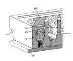
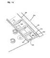
- FIG. 5is a front perspective view of an example implementation of a connector system including an optical connector being inserted into an optical adapter having movable stop members;
- FIG. 5Ais an enlarged view of a section of FIG. 5 ;
- FIG. 6is a perspective view of the optical connector of FIG. 5 in which the notch arrangement is visible;
- FIG. 7is a lateral cross-sectional view of the connector of FIG. 5 in which the cross-section is taken through the notch arrangement;
- FIG. 8is a perspective view of an example implementation of a stop member suitable for use in the coupler assemblies disclosed herein;
- FIG. 9is an axial cross-sectional view of the optical adapter of FIG. 5 with the optical connector plugged into one of the ports and the stop members in the unlocked position;
- FIG. 10is a lateral cross-sectional view of the optical adapter and optical connector of FIG. 9 ;
- FIG. 11is an axial cross-sectional view of the optical adapter of FIG. 5 with the optical connector plugged into one of the ports and the stop members in the locked position;
- FIG. 12is a lateral cross-sectional view of the optical adapter and optical connector of FIG. 11 ;
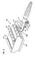
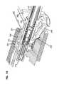
- FIG. 13is a front perspective view of another example implementation of a connector system including an optical connector being inserted into an optical adapter having movable stop members;
- FIG. 14is an enlarged top view of a section of the adapter shown in FIG. 13 ;
- FIG. 15is a perspective view of the stop member shown in FIG. 13 ;
- FIG. 16is an enlarged view of a section of the plug shown in FIG. 13 ;
- FIG. 17is a perspective view of the plug of FIG. 13 showing a transverse cross-sectional profile of the plug;
- FIG. 18is a perspective view of a plug inserted at an adapter port shown in cross-section so that a stop member is shown in an unlocked position;
- FIG. 19is a perspective view of a plug inserted at an adapter port shown in cross-section so that a stop member is shown in a locking position;
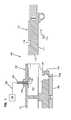
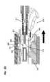
- FIG. 20is a longitudinal cross-sectional view of the adapter of FIG. 13 with the stop member in the locking position and the plug aligned for insertion into a port;
- FIG. 21is a longitudinal cross-sectional view of the adapter of FIG. 13 with the plug disposed in the port and the stop member engaged with the notches in the locking position;
- FIG. 22is a perspective view of the adapter and plug of FIG. 21 shown in transverse cross-section to that legs of the stop member are visible;
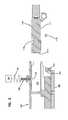
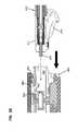
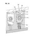
- FIG. 23is a longitudinal cross-sectional view of the adapter of FIG. 13 with the plug disposed in the port and the stop member in the unlocked position;
- FIG. 24is a perspective view of the adapter and plug of FIG. 23 shown in transverse cross-section to that legs of the stop member are visible;
- FIG. 25is a schematic block diagram of an example management system that is operationally coupled to equipment including one or more optical adapters that are configured in accordance with the principles of the present disclosure
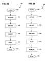
- FIG. 26is a flowchart illustrating an insertion process by which a user may securely plug a connector into an optical adapter
- FIG. 27is a flowchart illustrating an insertion authorization process by which the management system may decide whether or not to latch a connector within an optical adapter
- FIG. 28is a flowchart illustrating a removal process by which a user may remove a connector from an optical adapter
- FIG. 29is a flowchart illustrating a removal authorization process by which the management system may decide whether or not to unlatch a connector within an optical adapter.
- the present disclosurerelates to plug connectors and adapters that may be automatically secured and released via a management system.
- Such automationmay inhibit accidental and/or unauthorized insertion of plug connectors into adapter ports.
- the automationalso may inhibit accidental and/or unauthorized removal of the plug connectors from the ports.
- the plug connectorsare optical plug connectors (e.g., LC-type connectors, MPO-type connectors, SC-type connectors, LX.5-type connectors, etc.).
- the plug connectorsare electrical plug connectors (e.g., RJ45-type plugs, RJpoint5-type plugs, etc.).
- RJ45-type plugse.g., RJpoint5-type plugs, etc.
- the concepts disclosed hereinmay be applied to other types of plug connectors (e.g., MPO-type connectors, RJ45-type connectors, etc.) without deviating from the scope of the disclosure.
- FIGS. 1 and 2are schematic diagrams showing a connector system 100 including at least one plug-type connector plug 110 configured to be secured in a port 122 or socket of a connector assembly (e.g., optical adapter, electrical jack, etc.) 120 .
- the plug-type connector 110includes an optical connector that terminates one or more optical fibers.
- the plug-type connector 110may include an electrical plug that terminates one or more conductive wires. Signals from the terminated fibers or wires are accessible towards a front end 112 of the plug-type connector 110 .
- the connector 110includes a connector body 111 and a pivoting or flexible latching member that moves between an undeflected position and a deflected position.
- the latching memberincludes latching lugs 113 that define abutment surfaces 114 .
- the latching lugs 113also define a contoured (e.g., curved or ramped) surface that faces towards the front end 112 of the plug 110 .
- FIGS. 1 and 2one of the latching lugs 113 of the latching member is visible. It will be understood that lug 113 in FIGS. 1 and 2 is formed on a latching member that connects to the connector body 111 .
- the connector assembly 120includes an end section 123 defining a recess 123 .
- One side of the end section 123defines an abutment surface 123 a within the recess 124 .
- the abutment surface 123 afaces towards an interior of the connector assembly 120 .
- the latching member(and hence the latching lug 113 ) are biased towards the undeflected position. Accordingly, the latching member is disposed in the undeflected position when external of the coupler 120 (see FIG. 1 ).
- the contoured surface of the latching lug 113cams over the end section 123 to move the latching member to the deflected position.
- the latching lug 113clears the end section 123 and drops into the recess 124 when the latching member moves back to the undeflected position.
- the abutment surface 114 of the latching lug 113faces and engages the abutment surface 123 a of the coupler 120 to retain the plug 110 in the coupler 120 (see FIG. 2 ).
- the latching memberis flexed towards the deflected position until the abutment surface 114 clears the abutment surface 123 a of the coupler 120 .
- the coupler assembly 120includes a stop member 140 that is configured to selectively engage and disengage with the plug-type connector 110 by moving between an unlocked position and a locked position.
- the plug 110can be removed from the coupler 120 .
- the stop member 140is disposed in the locked position, the plug 110 cannot be removed from the coupler 120 .
- the plug 110cannot be inserted into the coupler 120 when the stop member 140 is disposed in the locked position. In other implementations, insertion of the plug 110 moves the stop member 140 to the unlocked position.
- the stop member 140is configured to move relative to the coupler 120 between a raised (i.e., unlocked) position and a lowered (i.e., locked) position.
- the coupler 120includes a support section 125 defining a passage 126 in which the stop member 140 may be disposed.
- the engagement end 145 of the stop member 140is disposed within the port 122 .
- an engagement end 145 of the stop member 140is disposed within the passage 126 when the stop member 140 is in the unlocked position.
- an engagement end 145 of the stop member 140is disposed partially within the port 122 when the stop member 140 is in the unlocked position, but not as far into the port 122 as when the stop member 140 is in the locked position.
- the body 111 of the plug-type connector 110defines at least one notch 115 sized to receive the lock member 140 .
- the notch 115is disposed at an opposite side of the plug 110 from the latching member.
- the notch 115can be disposed at any desired side of the plug 110 .
- a single notch 115extends across at least a portion of one side of the plug body 111 .
- a single notch 115extends completely across one side of the plug 110 .
- the plug body 111defines multiple notches 115 .
- one implementation of a plug body 111may define notches at corners on opposite ends of one side of the plug 110 (see FIG. 6 ).
- a notch 115may be defined at one corner or at only one end of one side of the plug 110 .
- other notch patternsare viable.
- the plug 110is releasably locked to the coupler 120 by lowering the stop member 140 into the notch or notches 115 defined in the plug body 111 .
- the lock member 140inhibits removal of the plug 110 while at least a portion of the stop member 140 is disposed in the notch or notches 115 .
- the plug 110is released by raising the stop member 140 out of the notch or notches 115 .
- the lock member 140is operationally coupled to (see connection 152 in FIGS. 1 and 2 ) and controlled by an actuator 150 .
- the actuator 150is a mechanical actuator that pulls and/or pushes the stop member 140 relative to the coupler 120 .
- the actuator 150otherwise controls (e.g., electrically, magnetically, etc.) movement of the stop member 140 between the locked and unlocked positions.
- the actuator 150will retain the stop feature 140 in the unlocked position before a plug 110 is inserted into the respective port 122 . Accordingly, a user is free to attempt insertion of the plug 110 when desired. In other implementations, however, the actuator 150 will retain the stop feature 140 in the locked position when the adapter port 122 is empty. In such implementations, the stop member 140 inhibits insertion of a plug 110 until the actuator 150 releases the stop member 140 .
- FIGS. 3 and 4illustrate one example implementation of the coupler 120 having a spring-biased stop member 140 .
- a coil spring 154 or other resilient memberis coupled to the stop member 140 to bias the engagement end 145 of the stop member 140 into the port 122 .
- the spring 154is controlled (e.g., selectively retained and released) by the actuator 150 .
- the actuator 150may retainer the stop member 140 in the unlocked position ( FIG. 3 ) against the bias of the spring 154 and selectively release the spring 154 to allow the spring 154 to move the stop member 140 to the locked position ( FIG. 4 ).
- the spring 154constantly biases the stop member 140 towards the locked position.
- the stop member 140 , the front end 112 of the plug body 111 , or bothmay define a contoured (e.g., curved or ramped) surface that would enable the stop feature 140 to cam over the plug body 111 against the bias of the spring 154 during insertion of the plug 110 into the coupler port 122 .
- the spring 154would push the stop member 140 into the notch 115 of the plug 110 when the plug 110 was sufficiently inserted to align the stop feature 140 with the notch 115 .
- a printed circuit board 130is mounted to the coupler assembly 120 to perform presence detection. Insertion of the plug 110 into the adapter port 122 may be detected by a processor coupled to the circuit board 130 . For example, insertion of the plug 110 may complete an electrical circuit at the circuit board 130 . In other implementations, insertion of the plug 110 may stop short-circuiting an electrical connection at the board 130 . In still other implementations, insertion of the plug 110 may actuate a pressure sensor or other sensing device mounted to the board 130 . In certain implementations, the actuator 150 is coupled to the sensing device or processor via the board 130 so that the detection of the plug 110 within the port 122 triggers the actuator 150 .
- the plug 110is configured to store information (e.g., physical layer information) and the coupler assembly 120 is configured to read information from the plug 110 when the plug 110 is inserted into the connector port 122 .
- the plug 110may include an EEPROM, an RFID tag, or other memory storage device.
- the printed circuit board 130couples an information reader at the coupler assembly 120 to a data management system.
- the readerincludes electrical contacts that physically touch electrical contacts on the plug 110 .
- the readerincludes an antenna coil and transceiver to read the RFID tag on the plug 110 .
- FIGS. 5-12illustrate one example implementation of a connector system 200 including at least one optical connector 210 configured to be secured in a port 222 of an optical adapter 220 .
- the optical adapter 220includes an adapter body 221 defining at least one port 222 .
- the adapter body 221defines four ports 222 at a front side and four ports 222 at a rear side. In other implementations, however, the adapter body 221 may define two ports, three ports, eight ports, twelve ports, or any desired number of ports 222 .
- the optical connector 210includes a connector body 211 holding a ferrule 212 at which an optical fiber is terminated.
- a latch arm 216extends from the connector body 211 and defines lug 213 having abutment surfaces 214 as described above.
- the optical connector 210also includes a notch arrangement 215 .
- the notch arrangement 215includes a first corner notch 215 a and a second corner notch 215 b that are located at opposite ends of one side 211 a of the connector 210 (see FIG. 6 ).
- the notch arrangement 215may include a greater or lesser number of notches 215 defined in any desired surface of the connector 210 .
- At least one stop member 240is moveable coupled to the optical adapter 220 to selectively lock the connector 210 within an adapter port 222 .
- the adapter 220includes a stop member 240 for each port 222 .
- the adapter 220includes a stop member 240 for each port 222 at only one side (e.g., the front or the rear) of the adapter 220 .
- the adapter 220includes four stop members 240 that are associated with the front ports 222 of the adapter 220 .
- a support region 225defines one or more passages 226 ( FIG. 9 ) in which the stop members 240 may be disposed.
- each stop member 240is disposed in its own passage 226 .
- the top of the support region 225forms a support wall 227 .
- each stop member 240includes a stop body 241 having an engagement end 245 and an actuation end 248 .
- the actuation end 248includes arms 246 extend laterally outwardly from the stop body 241 .
- the arms 248inhibit the stop member 240 from passing completely through the passage 226 .
- each arm 248defines an abutment surface 247 that seats on the support wall 227 when the stop member 240 is disposed in the locked position (see FIG. 12 ).
- the engagement end 245 of the stop member 240is sized and shaped to extend into the notch arrangement 215 of the plug 210 .
- the engagement end 245 of the stop member 240includes two legs 242 that extend downwardly from a plug-facing surface 243 .
- the plug-facing surface 243seats on the first side 211 a of the plug body 211 when the plug 210 is locked.
- the plug-facing surface 243is spaced from the plug body 211 even when the legs 242 extend into the plug notches 215 .
- contours 244are cut into inner sides of the legs 242 to match the contours of the corner notches 215 a , 215 b (see FIGS. 7 and 8 ).
- FIGS. 9 and 10illustrate the optical connector 210 inserted within an adapter port 222 with the stop members 240 disposed in the unlocked position.
- Each of the stop members 240is raised so that the arms 248 are spaced from the support wall 227 of the support region 225 .
- the engagement end 245 of the stop members 240is spaced from the notches 215 of the plug 210 .
- FIGS. 11 and 12illustrate the connector 210 locked in the adapter port 222 by a stop member 240 .
- the legs 242 a , 242 b( FIG. 12 ) are disposed in the corner notches 215 a , 215 b .
- the plug-facing surface 243seats on the first side 211 a of the plug body 211 .
- the arms 248 of the stop member 240seat on the support wall 227 of the support region 225 .
- one or more of the connectors 210may include a storage device 217 that stores information (e.g., physical layer information).
- the storage device 217includes conductive contacts that engage electrical contacts 229 disposed in the adapter 220 .
- the storage device 217may include or form part of an RFID tag that communicates with an RFID reader in the adapter 220 . The information is communicated from the reader to a data management system via a circuit board 230 .
- FIGS. 13-24illustrate another example of a connector system 300 including an optical connector 310 being inserted into an optical adapter 320 having movable stop members 340 .
- the optical adapter 320includes an adapter body 321 defining at least one port 322 that extends into the adapter body 321 .
- the adapter body 321defines four ports 322 at a front side and four ports 322 at a rear side. In other implementations, however, the adapter body 321 may define two ports, three ports, eight ports, twelve ports, or any desired number of ports 322 .
- the optical connector 310includes a connector body 311 holding a ferrule 312 at which an optical fiber is terminated.
- a latch arm 316extends from the connector body 311 and defines lug 313 having abutment surfaces 314 as described above.
- the optical connector 310also includes a notch arrangement 315 .
- the notch arrangement 315includes a first corner notch 315 a and a second corner notch 315 b that are located at opposite ends of one side 311 a of the connector 310 (see FIG. 17 ).
- each notch 315may define a locking surface 318 and a ramped or otherwise contoured surface 319 .
- the notch arrangement 315may include a greater or lesser number of notches 315 defined in any desired surface of the connector 310 .
- At least one stop member 340is moveable coupled to the optical adapter 320 to selectively lock the connector 310 within an adapter port 322 .
- the adapter 320includes a stop member 340 for each port 322 (e.g., see FIG. 14 ).
- the adapter 320includes a stop member 340 for each port 322 at only one side (e.g., the front or the rear) of the adapter 320 .
- the adapter 320includes four stop members 340 that are associated with the front ports 322 of the adapter 320 .
- a support region 325defines one or more cavities 323 in which the stop members 340 may be disposed.
- the cavities 323are recessed into the adapter 320 .
- each stop member 340is disposed in a corresponding cavity 323 .
- the stop members 340are disposed in one large cavity 323 .
- Each cavity 323defines a through-opening 329 that connect the cavity 323 with at least one of the ports 322 .
- Support surfaces 324are disposed within the passages 323 and extend across portions of the passages 323 to retain the stop members 340 .
- Lugs 326extend laterally into each passage 323 towards the respective support surface 324 .
- the top of the support region 325forms a support wall 327 around a perimeter of the support region 325 .
- the stop members 340are disposed within the passages 323 .
- Each stop member 340includes a stop body 341 having an engagement end 345 and an actuation end 348 .
- An actuation end 348 of each stop member 340seats on the support surface 324 within the passage 323 .
- the actuation end 348includes arms 346 that extend laterally outwardly from the stop body 341 .
- Each arm 348defines an abutment surface 347 that abuts a lug 326 extending laterally into the passage 323 to maintain the stop member 340 at the support surface 324 .
- the engagement end 345extends towards the passage 323 .
- the stop members 340are configured to move (e.g., pivot) relative to the adapter housing 321 between a locking position ( FIG. 19 ) and an unlocked position ( FIG. 18 ).
- the engagement end 345 of the stop member 340does not extend sufficiently into the adapter port 322 to interface with a plug connector 310 received at the adapter port 322 .
- the engagement end 345does not enter the port 322 when the stop member 340 is in the unlocked position.
- the stop member 340may extend generally horizontal to an insertion axis of the connector 310 within the port 322 .
- an engagement end 345 of the stop member 340extends through the passage 323 and into one of the ports 322 .
- the engagement end 345 of the stop member 340is sized and shaped to extend into the notch arrangement 315 of the plug 310 when the stop member 340 is in the locking position.
- the engagement end 345 of the stop member 340includes two legs 342 that extend downwardly from a plug-facing surface 343 .
- the plug-facing surface 343seats on the first side 311 a of the plug body 311 when the plug 310 is locked.
- the plug-facing surface 343is spaced from the plug body 311 even when the legs 342 extend into the plug notches 315 .
- contours 344are cut into inner sides of the legs 342 to match the contours of the corner notches 315 a , 315 b (see FIGS. 22 and 24 ).
- the stop members 340are controlled by actuators 350 ( FIGS. 20 , 21 , and 23 ).
- suitable actuators 350include mechanical actuators, electrical actuators, electro-magnetic actuators, electro-static actuators, thermal actuators, etc.
- the stop members 340may be spring-biased towards the locked position.
- an actuator (e.g., a micro-actuator) 350may releasably retain the stop member 340 against the bias of the spring until triggered.
- FIGS. 20-24illustrate the insertion and removal of the plug 310 into and from a port 322 of the adapter 320 .
- the plug 310is disposed outside of the port 322 and is moving towards the port 322 along an insertion axis I.
- the stop member 340 disposed at the port 322is in the locking position.
- the engagement end 345 of the stop member 340extends from the passage 323 sufficiently into the port 322 to interact with the plug body 311 when the plug body 311 is inserted at the port 322 .
- an actuator 350positions the stop member in the locking position.
- the stop member 340is spring-biased into the locking position.
- the stop member 340may be disposed in the unlocked position prior to insertion of the plug 310 at the port 322 .
- the plug body 311slides past the stop member 340 when the plug 310 is inserted at the port 322 .
- the plug body 311engages the engagement end 345 of the stop member 340 and pushes (e.g., cams) the stop member 340 towards the unlocked position sufficient to enable the plug body 311 to enter the port 322 .
- the stop member 340is spring biased towards the locking position. The plug body 311 overcomes the bias of the spring to move the stop member 340 towards the unlocked position.
- the actuator 350applies a force (e.g., magnetic, electrical, thermal, mechanical) to the stop member 340 that is overcome by the insertion movement of the plug body 311 .
- the stop member 340is moved to the locking position by gravity.
- the engagement end 345 of the stop member 340rides of the front of the plug 310 until snapping, falling, or otherwise entering the notch arrangement 315 defined in the plug 310 .
- the legs 342 of the stop member 340each enter one of the notches 315 of the plug 310 so that end surfaces of the legs 342 engage the locking surfaces 318 defined by the notches 315 . If a removal force is applied to the plug 310 (and the plug latch 316 is depressed), then the engagement between the legs 342 and the locking surfaces 318 maintain the plug 310 within the port 322 .
- the locking surfaces 318are shaped and oriented to not cause movement of the stop member 340 towards the unlocked position. In the example shown, the locking surfaces 318 are generally flat and oriented transverse to the insertion axis I of the plug 310 . In certain implementations, the legs 342 can rest against the ramped surfaces 319 of the notches 315 .
- the stop member 340is moved to the unlocked position to enable removal of the plug 310 .
- the actuator 350moves the stop member 340 to the unlocked position.
- the actuator 350moves the stop members 340 in response to a request made by a user through a data management network as will be described in more detail herein.
- the legs 342 of the stop member 340clear the notches 315 of the plug 310 and no longer engage with the locking surfaces 318 . Accordingly, if a removal force is applied to the plug 310 and the plug latch 316 is depressed, then the plug 310 is moved out of the port 322 .
- a pluge.g., a conventional plug
- the plug bodywill push/cam the stop member 340 towards the unlocked position to enable the plug 310 to enter the port 322 .
- the stop member 340will not engage the plug 310 . Accordingly, the stop member 340 will not retain such a plug within the port 322 . Rather, a plug latch will retain the plug within the port 322 until the latch is manually depressed.
- one or more adapters 120may be coupled together to form communications equipment 160 (e.g., a blade, a panel, etc.).
- the actuators 150are controlled by a management system 180 .
- the management system 180determines when the stop member 140 is moved to the locked position and when the stop member 140 is moved to the unlocked position. Accordingly, the management system 180 determines when the connector 110 is secured to the adapter 120 and when the connector 110 is releasable from the adapter 120 .
- the management system 180includes a local processor coupled to the adapter 120 or equipment including the adapter. In other implementations, the management system 180 includes a remote processor 182 coupled to the adapter 120 or equipment including the adapter 120 .
- the management system 180also includes memory 184 that may store processes or operation implemented by the processor 182 .
- the management system 180also may include a user interface module 186 with which one or more users communicate with the management system 180 . Additional details regarding example management systems suitable for use in controlling the actuator 150 as described in more detail below are disclosed in U.S. patent application Ser. No. 13/025,841, filed Feb. 11, 2011, and titled “Managed Fiber Connectivity Systems,” the disclosures of which are hereby incorporated herein by reference.
- the management system 180determines whether to authorize the insertion. If the insertion is authorized, then the connector 110 is latched in the adapter port. If the insertion is not authorized, then the connector 110 is not latched within the port. In some implementations, authorization is granted if the management system 180 expected a connection to be made at the port and the connector 110 matches predetermined criteria. In other implementations, a connector 110 need not be authorized and is automatically locked to the port when inserted into the port.
- the management system 180also controls an indicator arrangement mounted to the adapters 120 or to equipment including the adapters 120 .
- each adapter 120 of the equipment 160includes an indicator (e.g., an LED) with which the user's attention may be drawn to a particular adapter 120 on the equipment 160 .
- the equipment 160may include a display screen on which port identification (e.g., labels) may be listed.
- the communications equipment 160may be configured to otherwise identify a selected one of the adapters 120 .
- the management system 180determines when the indicator for each adapter 120 is activated (e.g., lit) and deactivated.
- FIG. 26is a flowchart illustrating an operational flow for an example insertion process 500 by which a user may plug a fiber optic connector 110 , 210 into an adapter 120 , 220 .
- the process stepsmay be implemented by one or more users. In certain implementations, the process steps herein described may occur at different times and/or locations.
- the insertion process 500begins at a start module 502 and proceeds to an access operation 504 .
- the usercommunicates with the management system 180 .
- the usermay communicate with the management system 180 via a direct connection to the user interface module 186 .
- the usermay communicate with the management system 180 via a networked computer or handheld processing device (e.g., smart phone, PDA, etc.) that is remotely connected (e.g., via a LAN, a WAN, the Internet, or another network) to the management system 180 .
- a networked computer or handheld processing devicee.g., smart phone, PDA, etc.
- the useridentifies the adapter port 122 , 222 at which the user wants to insert the connector 110 , 210 .
- the usermay view a port map and identify the port at which the connection should be made.
- the port mapis graphically displayed and the user selects an area on the graphic display.
- the usermay type or otherwise provide a port identification (e.g., a unique identification number) to the management system 180 .
- the useralso may provide the management system 180 with identifying characteristics of the connector 110 , 210 to be inserted. For example, the user may provide a unique identification number associated with the connector 110 , 210 . In other implementations, the user may provide a cable type, connector type, or other physical feature associated with the connector 110 , 210 . In still other implementations, the user may indicate that the connector 110 , 210 to be received is a managed connector (i.e., a connector 110 , 210 that includes memory storing physical layer information thereabout).
- a managed connectori.e., a connector 110 , 210 that includes memory storing physical layer information thereabout.
- the userpushes the connector 110 , 210 into an adapter port 122 , 222 .
- the userholds the connector 110 , 210 in the adapter port 122 , 222 (see hold operation 510 ) until the management system 180 indicates that an action has been taken.
- the actionincludes latching the connector 110 , 210 into the adapter port 122 , 222 if the management system 180 determines that insertion is authorized as disclosed in more detail below.
- the actionincludes issuing an alarm or error if the management system 180 determines that insertion is not authorized as disclosed in more detail below.
- the insertion operation 500performs any appropriate completion procedures and ends at a stop module 512 .
- FIG. 27is a flowchart illustrating an operational flow for an authorization process 520 by which the management system 180 determines whether or not a connector insertion is appropriate.
- the process stepsmay be implemented by one or more processors associated with the management system 180 . In certain implementations, the process steps are implemented locally at the adapter 120 , 220 or adapter equipment. In other implementations, the process steps are implemented at a location remote from the adapters 120 , 220 .
- the insertion authorization process 520begins at a start module 522 and proceeds to a determine operation 524 .
- the determine operation 524determines that a connector 110 , 210 has been or is being inserted into one of the adapters 120 , 220 associated with the management system 180 .
- the management system 180may determine that a switch has been opened or closed, thereby indicating that a connector 110 , 210 has been inserted into the adapter 120 , 220 .
- the determine operation 524may be implemented during or after insertion of the connector 110 , 210 into the adapter 120 , 220 .
- the connector 210pushes against electrical contacts 229 when inserted, thereby completing a circuit between the contacts 229 and a printed circuit board 230 associated with the adapter 220 .
- other types of presence sensorse.g., pressure sensors, light sensors, etc. may be utilized.
- An obtain operation 526reads or attempts to read data stored in the memory of the connector 110 , 210 . If the connector 110 , 210 being inserted includes memory 217 , then the obtain operation 526 retrieves some or all of the data stored in the memory and sends the data to the management system 180 for processing. In some implementations, the data is sent to a local processor at the adapter equipment. In other implementations, the data is sent to a remote processor. In some implementations, the obtain operation 526 retrieves a unique identifier associated with the connector 110 , 210 . In other implementations, the obtain operation 526 retrieves physical layer information (e.g., cable type, cable length, connector type, insertion count, security clearance, etc.) pertaining to the connector 110 , 210 or cable terminated thereat.
- physical layer informatione.g., cable type, cable length, connector type, insertion count, security clearance, etc.
- a determination module 528 implemented by the management system 180determines whether the insertion of the connector 110 , 210 at the adapter port 122 , 222 should be allowed. For example, in some implementations, the management system 180 determines whether a unique identifier read from the connector memory 217 matches an expected unique identifier provided by a user prior to the insertion. In other implementations, the management system 180 determines whether other types of data read from the memory 217 matches the expected data (e.g., whether the connector 110 , 210 is the expected connector type, whether the connector 110 , 210 terminates a cable of the expected cable type, whether the connector 110 , 210 is associated with the expected security clearance, etc.).
- the management system 180determines that authorization should be provided, then the management system 180 temporarily triggers the actuator 150 , 250 to move the stop member 140 , 240 at an actuate operation 530 .
- the management system 180may trigger the actuator 150 , 250 to lower the stop member 140 , 240 into the notch arrangement 115 , 215 of the connector 110 , 210 .
- the management system 180also may activates an indicator associated with the adapter port 122 , 222 or adapter equipment at an indicate operation 532 .
- the management system 180may light an LED or other light source associated with the port 122 , 222 . Activating the indicator tells the user that the connector 110 , 210 has been latched.
- the management system 180determines that authorization should not be provided, then the management system 180 implements an error operation 534 at which the user is informed that authorization is not granted.
- the error operation 534does not light an indicator light (e.g., LED) associated with the port.
- the error operation 534activates the indicator light with a warning color (e.g., red) or pattern (e.g., flashing).
- the error operation 534sounds an auditory alarm.
- the error operation 534sends an alert message to the user or to an administrator of the management network or security personnel.
- the management system 180implements an eject operation 536 at which the management system 180 instructs the adapter 120 , 220 to physically push or otherwise attempt to force the connector 110 , 210 out of the port 122 , 222 .
- An ejectorapplies a pressure to the connector 110 , 210 to push the connector 110 , 210 sufficiently out of the port 122 , 222 to prevent transmission of a signal from or to the connector 110 , 210 .
- the ejectorpushes the connector 110 , 210 completely outside of the adapter port 122 , 222 .
- the insertion authorization operation 520performs any appropriate completion procedures and ends at a stop module 538 .
- a connector 110 , 210may be removed from an adapter port 122 , 222 when the management system 180 determines that such a removal is authorized.
- a userprovides a request to the management system 180 that a particular connector 110 , 210 be unlatched to facilitate removal of the connector 110 , 210 from the port 122 , 222 .
- the usersignals the management system to unlatch the connector 110 , 210 .
- the management system 380unlatches the requested connector 110 , 210 .
- FIG. 28is a flowchart illustrating an operational flow for an example removal process 550 by which a user may pull or otherwise remove a fiber optic connector 110 , 210 from an adapter port 122 , 222 .
- the process stepsmay be implemented by one or more users. In certain implementations, the process steps herein described may occur at different times and/or locations.
- the removal process 550begins at a start module 552 and proceeds to an access operation 554 .
- the usercommunicates with the management system 180 .
- the usermay communicate with the management system 180 via a direct connection to the user interface module 186 .
- the usermay communicate with the management system 180 via a networked computer or handheld processing device (e.g., smart phone, PDA, etc.) that is remotely connected (e.g., via a LAN, a WAN, the Internet, or another network) to the management system 180 .
- a networked computer or handheld processing devicee.g., smart phone, PDA, etc.
- the useridentifies the adapter port 122 , 222 from which the user wants to remove the connector 110 , 210 and/or the user identifies the connector 110 , 210 that the user wants to remove.
- the usermay view a port map and identify the port at which the disconnection should be made.
- the port mapis graphically displayed and the user selects an area on the graphic display.
- the usermay type or otherwise provide a port identification (e.g., a unique identification number) and/or a connector identification to the management system 180 .
- the userpushes a button or otherwise actuates an input member to provide an indication to the management system 180 that the user is ready to remove a connector.
- the userpushes a button that is associated with multiple adapters 120 , 220 on a piece of adapter equipment.
- the userpushes a button associated with a particular adapter port 122 , 222 .
- the userdirectly depresses the button with a finger of the user.
- the userindirectly actuates the button as will be described in more detail herein.
- the userindicates readiness using a biometric device (e.g., a fingerprint scanner).
- the biometric deviceanalyzes biometric data (e.g., a scanned fingerprint) to identify the user.
- the management system 180may check whether the identified user is authorized to remove the connector 110 , 210 or otherwise modify the connections of the system.
- the userpushes the connector 110 , 210 forwardly into the adapter port 122 , 222 (see push operation 560 ) until the management system 180 indicates (e.g., via indicator) that an action has been taken.
- the userremoves stress on the latch 116 , 216 .
- the actionincludes unlatching the connector 110 , 210 .
- the actionmay include ejecting the connector 110 , 210 from the port 122 , 222 .
- the actionmay include issuing an alarm or error.
- the userimplements the push operation 560 before the indicate operation 558 .
- an internal input membermay be disposed within an adapter port 122 , 222 .
- the internal input memberis a micro-switch that is electrically connected to the circuit board 130 , 230 .
- pushing the connector 110 , 210 into the port 122 , 222actuates the internal input member, which triggers the management system 180 to act (e.g., trigger the actuator 150 , 250 to raise the stop member 140 , 240 ).
- the usermay pull the connector 110 , 210 out of the port 122 , 222 at a remove operation 362 .
- the removalmay be assisted by an ejector.
- the removal operation 550performs any appropriate completion procedures and ends at a stop module 564 .
- FIG. 29is a flowchart illustrating an operational flow for an authorization process 570 by which the management system 180 determines whether or not removal of a connector from an adapter port is appropriate.
- the process stepsmay be implemented by one or more processors associated with the management system 180 . In certain implementations, the process steps are implemented locally at the adapter 120 , 220 or adapter equipment. In other implementations, the process steps are implemented at a location remote from the adapters 120 , 220 .
- the removal authorization process 570begins at a start module 572 and proceeds to a receive operation 574 .
- the receive operation 574obtains a selection of a desired connector 120 , 220 to be removed (i.e., or an adapter port 122 , 222 from which a connector 120 , 220 is desired to be removed).
- the receive operation 574obtains a connector selection or port selection from a user via the user interface 186 of the management system 180 ( FIG. 25 ).
- the selectionis obtained using a graphic interface.
- the selectionis obtained via a port identification number (or alphanumeric code) or connector identification number (or alphanumeric code).
- the receiver operation 574obtains multiple selections from the user.
- a determine operation 576receives an indication from a user that the user is ready to disconnect the selected connector 120 , 220 (i.e., to disconnect the connector 120 , 220 plugged into the selected port 122 , 222 ).
- the determine operation 576may receive and process a signal from a push button or other input member actuated manually by the user.
- the input memberis located at the adapter 120 , 220 or adapter equipment.
- one input memberis associated with all ports 122 , 222 defined by the adapter equipment.
- each adapter port 122 , 222is associated with its own input member.
- a first determination module 578determines whether the readiness indication received in the determine operation 576 identifies a particular port 122 , 222 from which a connector 120 , 220 is to be removed (i.e., or a particular connector 300 to be removed). If the readiness indication does not identify a particular port 122 , 222 or connector 120 , 220 , then the management system 180 implements a trigger operation 580 to cause the actuator 150 , 150 associated with the port 122 , 222 identified in the receive operation 572 to raise the stop member 140 , 240 to release the connector 120 , 220 .
- the management system 180actuates an indicator to denote the connector 120 , 220 being unlatched from the port 122 , 222 .
- the indicatorvisually denotes unlatching (e.g., lights an LED, flashes an LED, changes the color of an LED).
- the indicatoraudibly denotes unlatching.
- the management system 180may actuate an ejection member during an eject operation 584 to aid in removing the unlatched connector 120 , 220 from the port 122 , 222 .
- the management system 180may release an ejector spring 358 to bias the connector 120 , 220 out of the port 122 , 222 .
- the management system 180implements a compare operation 586 that determines whether the user has identified the connector 120 , 220 preselected for removal. If the readiness indication identifies the preselected connector 120 , 220 or port 122 , 222 (see the second determination module 588 ), then the management system 180 implements the trigger operation 580 and proceeds as described above.
- the management system 180implements an error operation 590 .
- the second determination module 588determines that no connector 120 , 220 or port 122 , 222 has been preselected, then the management system 180 will proceed to the error operation 590 .
- the error operation 590provides an indication to the user that the user is attempting an unauthorized removal of a connector.
- the error operation 590may generate or trigger a visual alarm (e.g., a flashing LED), an audible alarm, or some other type of alert.
- the error operation 590will identify (e.g., flash an LED located at) the connector 120 , 220 preselected for removal.
- the removal authorization operation 570performs any appropriate completion procedures and ends at a stop module 592 .
- latching techniques and management systemcan be applied to other types of optical connectors (e.g., MPO connectors, LX.5 connectors, etc.), to electrical connectors (e.g., RJ45 connectors, RJpoint5 connectors, USB connectors, etc.) and sockets, or to hybrid or mixed media connectors and adapters.
- optical connectorse.g., MPO connectors, LX.5 connectors, etc.
- electrical connectorse.g., RJ45 connectors, RJpoint5 connectors, USB connectors, etc.
- socketse.g., RJ45 connectors, RJpoint5 connectors, USB connectors, etc.
Landscapes
- Physics & Mathematics (AREA)
- General Physics & Mathematics (AREA)
- Optics & Photonics (AREA)
- Mechanical Coupling Of Light Guides (AREA)
- Engineering & Computer Science (AREA)
- General Engineering & Computer Science (AREA)
- Mechanical Engineering (AREA)
- Details Of Connecting Devices For Male And Female Coupling (AREA)
Abstract
Description
Claims (10)
Priority Applications (3)
| Application Number | Priority Date | Filing Date | Title |
|---|---|---|---|
| US13/937,673US9075205B2 (en) | 2012-07-11 | 2013-07-09 | Connectors and adapters with auto-latching features |
| US14/749,315US9885841B2 (en) | 2012-07-11 | 2015-06-24 | Connectors and adapters with auto-latching features |
| US15/888,951US10761274B2 (en) | 2012-07-11 | 2018-02-05 | Connectors and adapters with auto-latching features |
Applications Claiming Priority (3)
| Application Number | Priority Date | Filing Date | Title |
|---|---|---|---|
| US201261670412P | 2012-07-11 | 2012-07-11 | |
| US201261707274P | 2012-09-28 | 2012-09-28 | |
| US13/937,673US9075205B2 (en) | 2012-07-11 | 2013-07-09 | Connectors and adapters with auto-latching features |
Related Child Applications (1)
| Application Number | Title | Priority Date | Filing Date |
|---|---|---|---|
| US14/749,315ContinuationUS9885841B2 (en) | 2012-07-11 | 2015-06-24 | Connectors and adapters with auto-latching features |
Publications (2)
| Publication Number | Publication Date |
|---|---|
| US20140016902A1 US20140016902A1 (en) | 2014-01-16 |
| US9075205B2true US9075205B2 (en) | 2015-07-07 |
Family
ID=49914059
Family Applications (3)
| Application Number | Title | Priority Date | Filing Date |
|---|---|---|---|
| US13/937,673Expired - Fee RelatedUS9075205B2 (en) | 2012-07-11 | 2013-07-09 | Connectors and adapters with auto-latching features |
| US14/749,315Active2033-07-20US9885841B2 (en) | 2012-07-11 | 2015-06-24 | Connectors and adapters with auto-latching features |
| US15/888,951ActiveUS10761274B2 (en) | 2012-07-11 | 2018-02-05 | Connectors and adapters with auto-latching features |
Family Applications After (2)
| Application Number | Title | Priority Date | Filing Date |
|---|---|---|---|
| US14/749,315Active2033-07-20US9885841B2 (en) | 2012-07-11 | 2015-06-24 | Connectors and adapters with auto-latching features |
| US15/888,951ActiveUS10761274B2 (en) | 2012-07-11 | 2018-02-05 | Connectors and adapters with auto-latching features |
Country Status (12)
| Country | Link |
|---|---|
| US (3) | US9075205B2 (en) |
| EP (1) | EP2872939A4 (en) |
| JP (1) | JP2015528185A (en) |
| KR (1) | KR20150032720A (en) |
| CN (2) | CN104603656B (en) |
| AU (1) | AU2013290212A1 (en) |
| BR (1) | BR112015000421A2 (en) |
| CA (1) | CA2878389A1 (en) |
| CL (1) | CL2015000070A1 (en) |
| IN (1) | IN2015DN00166A (en) |
| MX (1) | MX2015000036A (en) |
| WO (1) | WO2014011774A2 (en) |
Cited By (27)
| Publication number | Priority date | Publication date | Assignee | Title |
|---|---|---|---|---|
| JP6436376B1 (en)* | 2018-02-06 | 2018-12-12 | 広州市漫教雲境文化伝播有限公司 | Intelligent robot |
| US20190211536A1 (en)* | 2014-01-17 | 2019-07-11 | Gojo Industries, Inc. | Powered communication connection |
| US10359578B2 (en)* | 2015-07-01 | 2019-07-23 | Go!Foton Holdings, Inc. | Connector engagement sensing mechanism |
| JP2019138890A (en)* | 2018-02-06 | 2019-08-22 | 広州市漫教雲境文化伝播有限公司 | Intelligence detection robot |
| US10545299B2 (en) | 2015-07-01 | 2020-01-28 | Go!Foton Holdings, Inc. | Connector engagement sensing mechanism |
| US10761274B2 (en) | 2012-07-11 | 2020-09-01 | Commscope Technologies Llc | Connectors and adapters with auto-latching features |
| US10845548B2 (en) | 2015-07-01 | 2020-11-24 | Go!Foton Holdings, Inc. | Connector engagement sensing mechanism |
| US10985500B2 (en)* | 2017-03-15 | 2021-04-20 | Nicomatic | Connector assembly |
| US11112034B2 (en)* | 2019-06-18 | 2021-09-07 | Globalmedia Group, Llc | Cable keeper |
| US11215768B2 (en) | 2017-06-28 | 2022-01-04 | Corning Research & Development Corporation | Fiber optic connectors and connectorization employing adhesive admitting adapters |
| US11215769B2 (en) | 2019-03-07 | 2022-01-04 | Mellanox Technologies, Ltd. | MPO locking |
| US11300746B2 (en) | 2017-06-28 | 2022-04-12 | Corning Research & Development Corporation | Fiber optic port module inserts, assemblies and methods of making the same |
| US11372178B2 (en)* | 2015-09-10 | 2022-06-28 | Samtec, Inc. | Rack-mountable equipment with a high-heat-dissipation module, and transceiver receptacle with increased cooling |
| US11604320B2 (en) | 2020-09-30 | 2023-03-14 | Corning Research & Development Corporation | Connector assemblies for telecommunication enclosures |
| US11650388B2 (en) | 2019-11-14 | 2023-05-16 | Corning Research & Development Corporation | Fiber optic networks having a self-supporting optical terminal and methods of installing the optical terminal |
| US11668890B2 (en) | 2017-06-28 | 2023-06-06 | Corning Research & Development Corporation | Multiports and other devices having optical connection ports with securing features and methods of making the same |
| US11686913B2 (en) | 2020-11-30 | 2023-06-27 | Corning Research & Development Corporation | Fiber optic cable assemblies and connector assemblies having a crimp ring and crimp body and methods of fabricating the same |
| US11703646B2 (en) | 2017-06-28 | 2023-07-18 | Corning Research & Development Corporation | Multiports and optical connectors with rotationally discrete locking and keying features |
| US11880076B2 (en) | 2020-11-30 | 2024-01-23 | Corning Research & Development Corporation | Fiber optic adapter assemblies including a conversion housing and a release housing |
| US11886010B2 (en) | 2019-10-07 | 2024-01-30 | Corning Research & Development Corporation | Fiber optic terminals and fiber optic networks having variable ratio couplers |
| US11927810B2 (en) | 2020-11-30 | 2024-03-12 | Corning Research & Development Corporation | Fiber optic adapter assemblies including a conversion housing and a release member |
| US11947167B2 (en) | 2021-05-26 | 2024-04-02 | Corning Research & Development Corporation | Fiber optic terminals and tools and methods for adjusting a split ratio of a fiber optic terminal |
| US11994722B2 (en) | 2020-11-30 | 2024-05-28 | Corning Research & Development Corporation | Fiber optic adapter assemblies including an adapter housing and a locking housing |
| US12019279B2 (en) | 2019-05-31 | 2024-06-25 | Corning Research & Development Corporation | Multiports and other devices having optical connection ports with sliding actuators and methods of making the same |
| US20240210640A1 (en)* | 2022-12-27 | 2024-06-27 | Fujin Precision Industrial (Jincheng)Co.,Ltd. | Adapter, connector, and opto-electric transmission assembly |
| US12271040B2 (en) | 2017-06-28 | 2025-04-08 | Corning Research & Development Corporation | Fiber optic extender ports, assemblies and methods of making the same |
| US12372727B2 (en) | 2020-10-30 | 2025-07-29 | Corning Research & Development Corporation | Female fiber optic connectors having a rocker latch arm and methods of making the same |
Families Citing this family (59)
| Publication number | Priority date | Publication date | Assignee | Title |
|---|---|---|---|---|
| CA2873866A1 (en) | 2012-05-18 | 2013-11-21 | Adc Telecommunications, Inc. | Connectors and adapters with auto-latching features |
| WO2014009463A1 (en) | 2012-07-11 | 2014-01-16 | Tyco Electronics Uk Ltd. | Rfid-enabled optical adapter for use with a patch panel |
| ES2597840B1 (en)* | 2015-07-21 | 2017-12-13 | Ride On Consulting, S.L. | Anchoring system for electric bicycles |
| CN105353473B (en)* | 2015-09-29 | 2017-09-29 | 烽火通信科技股份有限公司 | A kind of electric connector for being installed on horizontal duplex LC type fiber adapter |
| EP3376271B1 (en)* | 2015-12-17 | 2021-09-01 | Huawei Technologies Co., Ltd. | Optical fibre adapter |
| CN106959491B (en)* | 2016-01-08 | 2019-07-26 | 菲尼萨公司 | Wire and cable connector |
| JP2017151338A (en)* | 2016-02-26 | 2017-08-31 | 三和電気工業株式会社 | Holder device for optical adapter |
| DE202016103178U1 (en)* | 2016-06-16 | 2016-07-07 | Reichle & De-Massari Ag | Connectors |
| CN107544116B (en)* | 2016-06-23 | 2021-11-23 | 中兴通讯股份有限公司 | Optical interface protection device, optical interface apparatus, and optical fiber apparatus |
| TW201820723A (en)* | 2016-11-23 | 2018-06-01 | 宇紘國際有限公司 | Micro embedded hole of network plug suitable for a micro buckle method of the lock body having an axial through hole just embedded in a predetermined position of the plug so that a micro buckle is also embedded into the micro embedded hole |
| CN108123303B (en)* | 2016-11-29 | 2020-08-18 | 宇纮国际有限公司 | The method that the micro-embedded hole of the network plug is suitable for the micro-buckle of the lock body |
| US10146014B2 (en)* | 2017-01-23 | 2018-12-04 | Corning Optical Communications LLC | Fiber optic assembly and method including pin section(s) for retaining fiber optic connector |
| US10185100B2 (en)* | 2017-01-30 | 2019-01-22 | Senko Advanced Components, Inc | Modular connector and adapter assembly using a removable anchor device |
| US10725248B2 (en) | 2017-01-30 | 2020-07-28 | Senko Advanced Components, Inc. | Fiber optic receptacle with integrated device therein incorporating a behind-the-wall fiber optic receptacle |
| US10871619B2 (en)* | 2017-01-30 | 2020-12-22 | Senko Advanced Components, Inc. | Cassette assembly for a plural of fiber optic receptacles |
| ES2999134T3 (en)* | 2017-02-01 | 2025-02-24 | Go Foton Holdings Inc | Connector engagement sensing mechanism |
| US9989712B1 (en)* | 2017-03-20 | 2018-06-05 | Senko Advanced Components, Inc | MPO connector assembly with push-pull tab |
| EP3382792B1 (en)* | 2017-03-30 | 2021-06-09 | TE Connectivity Germany GmbH | Microwave connector assembly |
| US9965655B1 (en)* | 2017-04-18 | 2018-05-08 | Erkios Systems, Inc. | Port security device for computing devices and methods of operating such |
| JP2020118700A (en)* | 2017-05-23 | 2020-08-06 | 住友電気工業株式会社 | Optical connector |
| JP1601196S (en)* | 2017-06-13 | 2018-04-09 | ||
| JP1601643S (en)* | 2017-06-13 | 2018-04-09 | ||
| JP1601645S (en)* | 2017-06-13 | 2018-04-09 | ||
| JP1601644S (en)* | 2017-06-13 | 2018-04-09 | ||
| JP1601642S (en)* | 2017-06-13 | 2018-04-09 | ||
| JP1601197S (en)* | 2017-06-13 | 2018-04-09 | ||
| CN109116475A (en)* | 2017-06-22 | 2019-01-01 | 中兴通讯股份有限公司 | The managing device and system of fiber active linker |
| CN110998398B (en)* | 2017-06-28 | 2022-09-06 | 康宁研究与开发公司 | Fiber extender port, assembly and method of making same |
| WO2019006191A1 (en)* | 2017-06-28 | 2019-01-03 | Corning Research & Development Corporation | Fiber optic port module inserts, assemblies and methods of making the same |
| US20230305257A1 (en)* | 2017-06-28 | 2023-09-28 | Corning Research & Development Corporation | Multiports and other devices having optical connection ports with securing features and methods of making the same |
| EP3646086A1 (en)* | 2017-06-28 | 2020-05-06 | Corning Research & Development Corporation | Fiber optic connectors |
| US11187859B2 (en) | 2017-06-28 | 2021-11-30 | Corning Research & Development Corporation | Fiber optic connectors and methods of making the same |
| US11226453B2 (en) | 2017-08-09 | 2022-01-18 | Commscope Technologies Llc | Board mounted active component assembly |
| JP7084263B2 (en)* | 2018-09-14 | 2022-06-14 | 三和電気工業株式会社 | Optical connector plug connection detection mechanism |
| US10641967B1 (en) | 2018-11-16 | 2020-05-05 | Corning Research & Development Corporation | Multiport assemblies including a modular adapter support array |
| US10768382B2 (en) | 2018-11-29 | 2020-09-08 | Corning Research & Development Corporation | Multiport assemblies including access apertures and a release tool |
| PT3903136T (en) | 2018-12-28 | 2024-12-05 | Corning Res & Dev Corp | Multiport assemblies including mounting features or dust plugs |
| CN113296198A (en)* | 2020-02-21 | 2021-08-24 | 佑胜光电股份有限公司 | Optical transmission assembly, optical transceiver module and optical fiber cable module |
| US10916889B1 (en)* | 2019-07-29 | 2021-02-09 | International Business Machines Corporation | Management of securable computing resources |
| US11341278B2 (en) | 2019-07-29 | 2022-05-24 | International Business Machines Corporation | Management of securable computing resources |
| US11669602B2 (en) | 2019-07-29 | 2023-06-06 | International Business Machines Corporation | Management of securable computing resources |
| US11531787B2 (en) | 2019-07-29 | 2022-12-20 | International Business Machines Corporation | Management of securable computing resources |
| US11341279B2 (en) | 2019-07-29 | 2022-05-24 | International Business Machines Corporation | Management of securable computing resources |
| US11210427B2 (en) | 2019-07-29 | 2021-12-28 | International Business Machines Corporation | Management of securable computing resources |
| US11294133B2 (en) | 2019-07-31 | 2022-04-05 | Corning Research & Development Corporation | Fiber optic networks using multiports and cable assemblies with cable-to-connector orientation |
| CN112510407B (en)* | 2019-09-16 | 2022-09-30 | 北京小米移动软件有限公司 | Female seat of Type-C, electronic system and adapter |
| US11487073B2 (en) | 2019-09-30 | 2022-11-01 | Corning Research & Development Corporation | Cable input devices having an integrated locking feature and assemblies using the cable input devices |
| US11289852B2 (en)* | 2020-02-07 | 2022-03-29 | International Business Machines Corporation | Detecting cable movement in physical ports |
| US11536921B2 (en) | 2020-02-11 | 2022-12-27 | Corning Research & Development Corporation | Fiber optic terminals having one or more loopback assemblies |
| US11682859B2 (en)* | 2020-02-24 | 2023-06-20 | Canon U.S.A., Inc. | Connector or bayonet style connector and methods for incorporating or using connector |
| CN112886295B (en)* | 2021-01-13 | 2023-01-10 | 珠海云鹤智能科技有限公司 | Wiring mechanism applied to circuit board |
| US11527851B2 (en)* | 2021-03-26 | 2022-12-13 | Hewlett Packard Enterprise Development Lp | Electronic port having a locking assembly for securing an electronic plug |
| CN113009643B (en)* | 2021-05-26 | 2021-08-20 | 中天宽带技术有限公司 | Prefabricated connector, coupler and prefabricated connector assembly |
| US12057659B2 (en)* | 2021-07-29 | 2024-08-06 | Hewlett Packard Enterprise Development Lp | Electronic port having a locking assembly for securing an electronic plug |
| US12368267B2 (en)* | 2021-09-15 | 2025-07-22 | Apple Inc. | Connector having a release button |
| CN113571957B (en)* | 2021-09-27 | 2021-12-10 | 山东渤海方略网络科技有限公司 | Network terminal communication connector |
| EP4599508A1 (en)* | 2022-10-07 | 2025-08-13 | Samtec Inc. | Method and apparatus for securing data communication devices |
| US12092701B2 (en)* | 2022-10-24 | 2024-09-17 | Dell Products L.P. | Connector seating detection system |
| US12386124B2 (en)* | 2022-11-30 | 2025-08-12 | Mellanox Technologies, Ltd. | Device for holding a plurality of ferrules against a respective plurality of receptacles |
Citations (20)
| Publication number | Priority date | Publication date | Assignee | Title |
|---|---|---|---|---|
| US6511231B2 (en) | 2000-12-27 | 2003-01-28 | Fitel Usa Corp. | Optical connector receptacle having switching capability |
| US20040101250A1 (en)* | 1996-06-28 | 2004-05-27 | Vergeest Henricus Jozef | Optical connector |
| US20040151464A1 (en)* | 2003-01-30 | 2004-08-05 | Marrs Samuel M. | Tuning tool for tunable fiber optic connector |
| JP2005115324A (en) | 2003-05-30 | 2005-04-28 | Sumitomo Electric Ind Ltd | Optical module |
| US6966788B1 (en) | 2005-03-15 | 2005-11-22 | Ruhl Jr Harold John | Anti-decoupling mechanism for solid or tubular circular cross section assemblies having a rotating coupling nut or nuts |
| US7128471B2 (en)* | 2004-05-06 | 2006-10-31 | Avago Technologies Fiber Ip (Singapore) Pte. Ltd. | Single-use fiber optic cable |
| US7226217B1 (en) | 2005-11-18 | 2007-06-05 | Stratos International, Inc. | Transceiver/fiber optic connector adaptor with patch cord ID reading capability |
| US7229220B2 (en) | 2003-12-06 | 2007-06-12 | Hon Hai Precision Ind. Co., Ltd. | Optical fiber connector |
| WO2007103689A2 (en) | 2006-03-01 | 2007-09-13 | Panduit Corp. | Plug locking assembly |
| US20080116678A1 (en) | 2005-02-08 | 2008-05-22 | Polycontact Ag | Insertion Part for a Seat Belt Lock, a Lock Provided with Said Insertion Part |
| WO2009006400A1 (en) | 2007-07-03 | 2009-01-08 | Panduit Corp. | Plug locking assembly and system |
| US7494363B1 (en) | 2008-06-27 | 2009-02-24 | Hon Hai Precision Ind. Co., Ltd. | Plug connector having a latching mechanism |
| US20090269943A1 (en) | 2007-12-24 | 2009-10-29 | Craig Palli | Magnetic and Locking Cable Connectors |
| US20100029117A1 (en) | 2008-08-01 | 2010-02-04 | Verizon Corporate Services Group Inc. | Computer-controlled connector-panel system |
| US20100233889A1 (en) | 2009-03-11 | 2010-09-16 | Kiani Massi Joe E | Magnetic connector |
| US20110222819A1 (en) | 2010-02-12 | 2011-09-15 | John Anderson | Managed fiber connectivity systems |
| US20110317976A1 (en) | 2008-12-01 | 2011-12-29 | Reichle & De-Massari Ag | Security system for optical plug-in connector |
| US20120148195A1 (en) | 2010-12-09 | 2012-06-14 | Microsoft Corporation | Power and data connector |
| US20120155803A1 (en) | 2010-12-07 | 2012-06-21 | Benjamin Seldon D | Ferrule assemblies, connector assemblies, and optical couplings having coded magnetic arrays |
| US20130323940A1 (en) | 2012-05-18 | 2013-12-05 | Tyco Electronics Corporation | Connectors and adapters with auto-latching features |
Family Cites Families (11)
| Publication number | Priority date | Publication date | Assignee | Title |
|---|---|---|---|---|
| US6375362B1 (en)* | 1999-05-04 | 2002-04-23 | Siemens Aktiengesellschaft | Optical plug-type connection |
| US6304436B1 (en)* | 1999-12-03 | 2001-10-16 | International Business Machines Corporation | Connector system with outwardly opening door for a removable transceiver module |
| US7073953B2 (en)* | 2001-08-31 | 2006-07-11 | Amphenol Corporation | Modular fiber optic connection system |
| US6808116B1 (en)* | 2002-05-29 | 2004-10-26 | At&T Corp. | Fiber jumpers with data storage method and apparatus |
| JP2005084162A (en)* | 2003-09-05 | 2005-03-31 | Tokyo Tsushinki Kogyo Kk | Wiring management apparatus |
| US7878667B2 (en)* | 2007-11-09 | 2011-02-01 | Mario Rabinowitz | Latching solar concentrator pivoted mirrors during off-power period |
| US8267594B2 (en)* | 2008-02-01 | 2012-09-18 | Applied Optical Systems, Inc. | Quick release connection |
| US7787740B2 (en)* | 2008-06-12 | 2010-08-31 | Corning Cable Systems Llc | Universal cable bracket |
| DE102009016504A1 (en)* | 2009-04-08 | 2011-04-21 | Rwe Ag | Charging cable locking device and method for locking a cable |
| WO2011047288A1 (en)* | 2009-10-16 | 2011-04-21 | Adc Telecommunications, Inc. | Managed connectivity in fiber optic systems and methods thereof |
| US9075205B2 (en) | 2012-07-11 | 2015-07-07 | Tyco Electronics Corporation | Connectors and adapters with auto-latching features |
- 2013
- 2013-07-09USUS13/937,673patent/US9075205B2/ennot_activeExpired - Fee Related
- 2013-07-10ININ166DEN2015patent/IN2015DN00166A/enunknown
- 2013-07-10JPJP2015521777Apatent/JP2015528185A/ennot_activeWithdrawn
- 2013-07-10CNCN201380036830.3Apatent/CN104603656B/ennot_activeExpired - Fee Related
- 2013-07-10KRKR20157001581Apatent/KR20150032720A/ennot_activeWithdrawn
- 2013-07-10BRBR112015000421Apatent/BR112015000421A2/ennot_activeIP Right Cessation
- 2013-07-10MXMX2015000036Apatent/MX2015000036A/ennot_activeApplication Discontinuation
- 2013-07-10WOPCT/US2013/049928patent/WO2014011774A2/enactiveApplication Filing
- 2013-07-10CACA2878389Apatent/CA2878389A1/ennot_activeAbandoned
- 2013-07-10AUAU2013290212Apatent/AU2013290212A1/ennot_activeAbandoned
- 2013-07-10CNCN201610890520.3Apatent/CN106886073A/enactivePending
- 2013-07-10EPEP13816261.5Apatent/EP2872939A4/ennot_activeWithdrawn
- 2015
- 2015-01-09CLCL2015000070Apatent/CL2015000070A1/enunknown
- 2015-06-24USUS14/749,315patent/US9885841B2/enactiveActive
- 2018
- 2018-02-05USUS15/888,951patent/US10761274B2/enactiveActive
Patent Citations (23)
| Publication number | Priority date | Publication date | Assignee | Title |
|---|---|---|---|---|
| US20040101250A1 (en)* | 1996-06-28 | 2004-05-27 | Vergeest Henricus Jozef | Optical connector |
| US6511231B2 (en) | 2000-12-27 | 2003-01-28 | Fitel Usa Corp. | Optical connector receptacle having switching capability |
| US20040151464A1 (en)* | 2003-01-30 | 2004-08-05 | Marrs Samuel M. | Tuning tool for tunable fiber optic connector |
| JP2005115324A (en) | 2003-05-30 | 2005-04-28 | Sumitomo Electric Ind Ltd | Optical module |
| US7229220B2 (en) | 2003-12-06 | 2007-06-12 | Hon Hai Precision Ind. Co., Ltd. | Optical fiber connector |
| US7128471B2 (en)* | 2004-05-06 | 2006-10-31 | Avago Technologies Fiber Ip (Singapore) Pte. Ltd. | Single-use fiber optic cable |
| US20080116678A1 (en) | 2005-02-08 | 2008-05-22 | Polycontact Ag | Insertion Part for a Seat Belt Lock, a Lock Provided with Said Insertion Part |
| US6966788B1 (en) | 2005-03-15 | 2005-11-22 | Ruhl Jr Harold John | Anti-decoupling mechanism for solid or tubular circular cross section assemblies having a rotating coupling nut or nuts |
| US7226217B1 (en) | 2005-11-18 | 2007-06-05 | Stratos International, Inc. | Transceiver/fiber optic connector adaptor with patch cord ID reading capability |
| WO2007103689A2 (en) | 2006-03-01 | 2007-09-13 | Panduit Corp. | Plug locking assembly |
| WO2009006400A1 (en) | 2007-07-03 | 2009-01-08 | Panduit Corp. | Plug locking assembly and system |
| US20090269943A1 (en) | 2007-12-24 | 2009-10-29 | Craig Palli | Magnetic and Locking Cable Connectors |
| US7494363B1 (en) | 2008-06-27 | 2009-02-24 | Hon Hai Precision Ind. Co., Ltd. | Plug connector having a latching mechanism |
| US20100029117A1 (en) | 2008-08-01 | 2010-02-04 | Verizon Corporate Services Group Inc. | Computer-controlled connector-panel system |
| US20110317976A1 (en) | 2008-12-01 | 2011-12-29 | Reichle & De-Massari Ag | Security system for optical plug-in connector |
| US20100233889A1 (en) | 2009-03-11 | 2010-09-16 | Kiani Massi Joe E | Magnetic connector |
| US20110222819A1 (en) | 2010-02-12 | 2011-09-15 | John Anderson | Managed fiber connectivity systems |
| US20110235979A1 (en) | 2010-02-12 | 2011-09-29 | John Anderson | Managed fiber connectivity systems |
| US20110255829A1 (en) | 2010-02-12 | 2011-10-20 | John Anderson | Managed fiber connectivity systems |
| US20110262077A1 (en) | 2010-02-12 | 2011-10-27 | John Anderson | Managed fiber connectivity systems |
| US20120155803A1 (en) | 2010-12-07 | 2012-06-21 | Benjamin Seldon D | Ferrule assemblies, connector assemblies, and optical couplings having coded magnetic arrays |
| US20120148195A1 (en) | 2010-12-09 | 2012-06-14 | Microsoft Corporation | Power and data connector |
| US20130323940A1 (en) | 2012-05-18 | 2013-12-05 | Tyco Electronics Corporation | Connectors and adapters with auto-latching features |
Non-Patent Citations (2)
| Title |
|---|
| International Search Report and Written Opinion for PCT/US2013/041612 mailed Aug. 27, 2013. |
| International Search Report and Written Opinion for PCT/US2013/049928 mailed Oct. 22, 2013. |
Cited By (57)
| Publication number | Priority date | Publication date | Assignee | Title |
|---|---|---|---|---|
| US10761274B2 (en) | 2012-07-11 | 2020-09-01 | Commscope Technologies Llc | Connectors and adapters with auto-latching features |
| US20190211536A1 (en)* | 2014-01-17 | 2019-07-11 | Gojo Industries, Inc. | Powered communication connection |
| US10359578B2 (en)* | 2015-07-01 | 2019-07-23 | Go!Foton Holdings, Inc. | Connector engagement sensing mechanism |
| US11391893B2 (en) | 2015-07-01 | 2022-07-19 | Go!Foton Holdings, Inc. | Connector engagement sensing mechanism |
| US10545299B2 (en) | 2015-07-01 | 2020-01-28 | Go!Foton Holdings, Inc. | Connector engagement sensing mechanism |
| US10690862B2 (en) | 2015-07-01 | 2020-06-23 | Go!Foton Holdings, Inc. | Connector engagement sensing mechanism |
| US10845548B2 (en) | 2015-07-01 | 2020-11-24 | Go!Foton Holdings, Inc. | Connector engagement sensing mechanism |
| US11372178B2 (en)* | 2015-09-10 | 2022-06-28 | Samtec, Inc. | Rack-mountable equipment with a high-heat-dissipation module, and transceiver receptacle with increased cooling |
| US10985500B2 (en)* | 2017-03-15 | 2021-04-20 | Nicomatic | Connector assembly |
| US11789214B2 (en) | 2017-06-28 | 2023-10-17 | Corning Research & Development Corporation | Multiports and other devices having keyed connection ports and securing features and methods of making the same |
| US11668890B2 (en) | 2017-06-28 | 2023-06-06 | Corning Research & Development Corporation | Multiports and other devices having optical connection ports with securing features and methods of making the same |
| US12092878B2 (en) | 2017-06-28 | 2024-09-17 | Corning Research & Development Corporation | Fiber optic connectors having a keying structure and methods of making the same |
| US11287581B2 (en)* | 2017-06-28 | 2022-03-29 | Corning Research & Development Corporation | Compact fiber optic connectors, cable assemblies and methods of making the same |
| US11300746B2 (en) | 2017-06-28 | 2022-04-12 | Corning Research & Development Corporation | Fiber optic port module inserts, assemblies and methods of making the same |
| US12429655B2 (en) | 2017-06-28 | 2025-09-30 | Corning Optical Communications LLC | Multiports having connection ports with associated securing features and methods of making the same |
| US12013578B2 (en) | 2017-06-28 | 2024-06-18 | Corning Research & Development Corporation | Multifiber fiber optic connectors, cable assemblies and methods of making the same |
| US11409055B2 (en) | 2017-06-28 | 2022-08-09 | Corning Optical Communications LLC | Multiports having connection ports with associated securing features and methods of making the same |
| US11415759B2 (en) | 2017-06-28 | 2022-08-16 | Corning Optical Communications LLC | Multiports having a connection port insert and methods of making the same |
| US11460646B2 (en) | 2017-06-28 | 2022-10-04 | Corning Research & Development Corporation | Fiber optic connectors and multiport assemblies including retention features |
| US11487065B2 (en) | 2017-06-28 | 2022-11-01 | Corning Research & Development Corporation | Multiports and devices having a connector port with a rotating securing feature |
| US11536913B2 (en) | 2017-06-28 | 2022-12-27 | Corning Research & Development Corporation | Fiber optic connectors and connectorization employing adhesive admitting adapters |
| US11579377B2 (en) | 2017-06-28 | 2023-02-14 | Corning Research & Development Corporation | Compact fiber optic connectors, cable assemblies and methods of making the same with alignment elements |
| US12379552B2 (en) | 2017-06-28 | 2025-08-05 | Corning Research & Development Corporation | Compact fiber optic connectors, cable assemblies and methods of making the same |
| US11624877B2 (en) | 2017-06-28 | 2023-04-11 | Corning Research & Development Corporation | Multiports having connection ports with securing features that actuate flexures and methods of making the same |
| US12379551B2 (en) | 2017-06-28 | 2025-08-05 | Corning Optical Communications LLC | Multiports having connection ports formed in the shell and associated securing features |
| US11656414B2 (en) | 2017-06-28 | 2023-05-23 | Corning Research & Development Corporation | Multiports and other devices having connection ports with securing features and methods of making the same |
| US11215768B2 (en) | 2017-06-28 | 2022-01-04 | Corning Research & Development Corporation | Fiber optic connectors and connectorization employing adhesive admitting adapters |
| US12353024B2 (en) | 2017-06-28 | 2025-07-08 | Corning Research & Development Corporation | Multiports and optical connectors with rotationally discrete locking and keying features |
| US11703646B2 (en) | 2017-06-28 | 2023-07-18 | Corning Research & Development Corporation | Multiports and optical connectors with rotationally discrete locking and keying features |
| US12174432B2 (en) | 2017-06-28 | 2024-12-24 | Corning Research & Development Corporation | Fiber optic connectors and connectorization employing adhesive admitting adapters |
| US12353025B2 (en) | 2017-06-28 | 2025-07-08 | Corning Optical Communications LLC | Multiports having a connection port insert and methods of making the same |
| US11886017B2 (en) | 2017-06-28 | 2024-01-30 | Corning Research & Development Corporation | Multiports and other devices having connection ports with securing features and methods of making the same |
| US12298568B2 (en) | 2017-06-28 | 2025-05-13 | Corning Research & Development Corporation | Fiber optic connectors and multiport assemblies including retention features |
| US11906792B2 (en) | 2017-06-28 | 2024-02-20 | Corning Research & Development Corporation | Compact fiber optic connectors having multiple connector footprints, along with cable assemblies and methods of making the same |
| US11914197B2 (en) | 2017-06-28 | 2024-02-27 | Corning Research & Development Corporation | Compact fiber optic connectors having multiple connector footprints, along with cable assemblies and methods of making the same |
| US11914198B2 (en) | 2017-06-28 | 2024-02-27 | Corning Research & Development Corporation | Compact fiber optic connectors having multiple connector footprints, along with cable assemblies and methods of making the same |
| US12276846B2 (en) | 2017-06-28 | 2025-04-15 | Corning Research & Development Corporation | Compact fiber optic connectors, cable assemblies and methods of making the same |
| US11940656B2 (en) | 2017-06-28 | 2024-03-26 | Corning Research & Development Corporation | Compact fiber optic connectors, cable assemblies and methods of making the same |
| US12271040B2 (en) | 2017-06-28 | 2025-04-08 | Corning Research & Development Corporation | Fiber optic extender ports, assemblies and methods of making the same |
| US11966089B2 (en) | 2017-06-28 | 2024-04-23 | Corning Optical Communications, Llc | Multiports having connection ports formed in the shell and associated securing features |
| JP6436376B1 (en)* | 2018-02-06 | 2018-12-12 | 広州市漫教雲境文化伝播有限公司 | Intelligent robot |
| JP2019138890A (en)* | 2018-02-06 | 2019-08-22 | 広州市漫教雲境文化伝播有限公司 | Intelligence detection robot |
| US11215769B2 (en) | 2019-03-07 | 2022-01-04 | Mellanox Technologies, Ltd. | MPO locking |
| US12019279B2 (en) | 2019-05-31 | 2024-06-25 | Corning Research & Development Corporation | Multiports and other devices having optical connection ports with sliding actuators and methods of making the same |
| US11112034B2 (en)* | 2019-06-18 | 2021-09-07 | Globalmedia Group, Llc | Cable keeper |
| US11886010B2 (en) | 2019-10-07 | 2024-01-30 | Corning Research & Development Corporation | Fiber optic terminals and fiber optic networks having variable ratio couplers |
| US11650388B2 (en) | 2019-11-14 | 2023-05-16 | Corning Research & Development Corporation | Fiber optic networks having a self-supporting optical terminal and methods of installing the optical terminal |
| US12019285B2 (en) | 2020-09-30 | 2024-06-25 | Corning Research & Development Corporation | Connector assemblies for telecommunication enclosures |
| US11604320B2 (en) | 2020-09-30 | 2023-03-14 | Corning Research & Development Corporation | Connector assemblies for telecommunication enclosures |
| US12372727B2 (en) | 2020-10-30 | 2025-07-29 | Corning Research & Development Corporation | Female fiber optic connectors having a rocker latch arm and methods of making the same |
| US12345927B2 (en) | 2020-11-30 | 2025-07-01 | Corning Research & Development Corporation | Fiber optic adapter assemblies including a conversion housing and a release housing |
| US11880076B2 (en) | 2020-11-30 | 2024-01-23 | Corning Research & Development Corporation | Fiber optic adapter assemblies including a conversion housing and a release housing |
| US11686913B2 (en) | 2020-11-30 | 2023-06-27 | Corning Research & Development Corporation | Fiber optic cable assemblies and connector assemblies having a crimp ring and crimp body and methods of fabricating the same |
| US11927810B2 (en) | 2020-11-30 | 2024-03-12 | Corning Research & Development Corporation | Fiber optic adapter assemblies including a conversion housing and a release member |
| US11994722B2 (en) | 2020-11-30 | 2024-05-28 | Corning Research & Development Corporation | Fiber optic adapter assemblies including an adapter housing and a locking housing |
| US11947167B2 (en) | 2021-05-26 | 2024-04-02 | Corning Research & Development Corporation | Fiber optic terminals and tools and methods for adjusting a split ratio of a fiber optic terminal |
| US20240210640A1 (en)* | 2022-12-27 | 2024-06-27 | Fujin Precision Industrial (Jincheng)Co.,Ltd. | Adapter, connector, and opto-electric transmission assembly |
Also Published As
| Publication number | Publication date |
|---|---|
| US20140016902A1 (en) | 2014-01-16 |
| CN104603656B (en) | 2016-11-09 |
| BR112015000421A2 (en) | 2017-06-27 |
| KR20150032720A (en) | 2015-03-27 |
| CN104603656A (en) | 2015-05-06 |
| AU2013290212A1 (en) | 2015-01-29 |
| CL2015000070A1 (en) | 2015-08-07 |
| CN106886073A (en) | 2017-06-23 |
| EP2872939A4 (en) | 2016-03-02 |
| MX2015000036A (en) | 2015-06-04 |
| WO2014011774A2 (en) | 2014-01-16 |
| CA2878389A1 (en) | 2014-01-16 |
| US10761274B2 (en) | 2020-09-01 |
| EP2872939A2 (en) | 2015-05-20 |
| JP2015528185A (en) | 2015-09-24 |
| US9885841B2 (en) | 2018-02-06 |
| US20180246283A1 (en) | 2018-08-30 |
| IN2015DN00166A (en) | 2015-06-12 |
| US20150346436A1 (en) | 2015-12-03 |
| WO2014011774A3 (en) | 2014-04-10 |
Similar Documents
| Publication | Publication Date | Title |
|---|---|---|
| US10761274B2 (en) | Connectors and adapters with auto-latching features | |
| US9063298B2 (en) | Connectors and adapters with auto-latching features | |
| US12306444B2 (en) | Managed fiber connectivity systems | |
| US20170108653A1 (en) | Managed fiber connectivity systems | |
| US9946037B2 (en) | RFID-enabled optical adapter for use with a patch panel | |
| CN107111801B (en) | Multi-tier intelligent infrastructure management system for communication systems and related apparatus and methods | |
| US8421626B2 (en) | Radio frequency identification transponder for communicating condition of a component | |
| US6652155B2 (en) | Optical connector plug | |
| WO2015023768A1 (en) | Inferring physical layer connection status of generic cables from planned single-end connection events | |
| US20140223587A1 (en) | Transceiver locking assembly | |
| JP4209208B2 (en) | Data tag for optical connector and optical connector with attached data tag |
Legal Events
| Date | Code | Title | Description |
|---|---|---|---|
| AS | Assignment | Owner name:TYCO ELECTRONICS CORPORATION, PENNSYLVANIA Free format text:ASSIGNMENT OF ASSIGNORS INTEREST;ASSIGNOR:PEPE, PAUL JOHN;REEL/FRAME:030889/0601 Effective date:20130715 Owner name:ADC TELECOMMUNICATIONS, INC., PENNSYLVANIA Free format text:ASSIGNMENT OF ASSIGNORS INTEREST;ASSIGNOR:COFFEY, JOSEPH CHRISTOPHER;REEL/FRAME:030878/0522 Effective date:20130715 | |
| AS | Assignment | Owner name:TYCO ELECTRONICS CORPORATION, PENNSYLVANIA Free format text:CORRECTIVE ASSIGNMENT TO CORRECT THE ASSIGNEE ADDRESS PREVIOUSLY RECORDED ON REEL 030889 FRAME 0601. ASSIGNOR(S) HEREBY CONFIRMS THE WESLAKES SHOULD BE WESTLAKES;ASSIGNOR:PEPE, PAUL JOHN;REEL/FRAME:030911/0105 Effective date:20130715 Owner name:ADC TELECOMMUNICATIONS, INC., PENNSYLVANIA Free format text:CORRECTIVE ASSIGNMENT TO CORRECT THE ASSIGNEE ADDRESS PREVIOUSLY RECORDED ON REEL 030878 FRAME 0522. ASSIGNOR(S) HEREBY CONFIRMS THE WESLAKES SHOULD BE WESTLAKES;ASSIGNOR:COFFEY, JOSEPH CHRISTOPHER;REEL/FRAME:030911/0129 Effective date:20130715 | |
| STCF | Information on status: patent grant | Free format text:PATENTED CASE | |
| AS | Assignment | Owner name:ADC TELECOMMUNICATIONS, INC., PENNSYLVANIA Free format text:ASSIGNMENT OF ASSIGNORS INTEREST;ASSIGNOR:TYCO ELECTRONICS CORPORATION;REEL/FRAME:036907/0571 Effective date:20150824 | |
| AS | Assignment | Owner name:TYCO ELECTRONICS SERVICES GMBH, SWITZERLAND Free format text:ASSIGNMENT OF ASSIGNORS INTEREST;ASSIGNORS:ADC TELECOMMUNICATIONS, INC.;TE CONNECTIVITY SOLUTIONS GMBH;REEL/FRAME:036908/0443 Effective date:20150825 | |
| AS | Assignment | Owner name:COMMSCOPE EMEA LIMITED, IRELAND Free format text:ASSIGNMENT OF ASSIGNORS INTEREST;ASSIGNOR:TYCO ELECTRONICS SERVICES GMBH;REEL/FRAME:036956/0001 Effective date:20150828 | |
| AS | Assignment | Owner name:COMMSCOPE TECHNOLOGIES LLC, NORTH CAROLINA Free format text:ASSIGNMENT OF ASSIGNORS INTEREST;ASSIGNOR:COMMSCOPE EMEA LIMITED;REEL/FRAME:037012/0001 Effective date:20150828 | |
| AS | Assignment | Owner name:JPMORGAN CHASE BANK, N.A., AS COLLATERAL AGENT, ILLINOIS Free format text:PATENT SECURITY AGREEMENT (TERM);ASSIGNOR:COMMSCOPE TECHNOLOGIES LLC;REEL/FRAME:037513/0709 Effective date:20151220 Owner name:JPMORGAN CHASE BANK, N.A., AS COLLATERAL AGENT, ILLINOIS Free format text:PATENT SECURITY AGREEMENT (ABL);ASSIGNOR:COMMSCOPE TECHNOLOGIES LLC;REEL/FRAME:037514/0196 Effective date:20151220 Owner name:JPMORGAN CHASE BANK, N.A., AS COLLATERAL AGENT, IL Free format text:PATENT SECURITY AGREEMENT (TERM);ASSIGNOR:COMMSCOPE TECHNOLOGIES LLC;REEL/FRAME:037513/0709 Effective date:20151220 Owner name:JPMORGAN CHASE BANK, N.A., AS COLLATERAL AGENT, IL Free format text:PATENT SECURITY AGREEMENT (ABL);ASSIGNOR:COMMSCOPE TECHNOLOGIES LLC;REEL/FRAME:037514/0196 Effective date:20151220 | |
| CC | Certificate of correction | ||
| FEPP | Fee payment procedure | Free format text:MAINTENANCE FEE REMINDER MAILED (ORIGINAL EVENT CODE: REM.); ENTITY STATUS OF PATENT OWNER: LARGE ENTITY | |
| AS | Assignment | Owner name:REDWOOD SYSTEMS, INC., NORTH CAROLINA Free format text:RELEASE BY SECURED PARTY;ASSIGNOR:JPMORGAN CHASE BANK, N.A.;REEL/FRAME:048840/0001 Effective date:20190404 Owner name:ALLEN TELECOM LLC, ILLINOIS Free format text:RELEASE BY SECURED PARTY;ASSIGNOR:JPMORGAN CHASE BANK, N.A.;REEL/FRAME:048840/0001 Effective date:20190404 Owner name:COMMSCOPE, INC. OF NORTH CAROLINA, NORTH CAROLINA Free format text:RELEASE BY SECURED PARTY;ASSIGNOR:JPMORGAN CHASE BANK, N.A.;REEL/FRAME:048840/0001 Effective date:20190404 Owner name:ANDREW LLC, NORTH CAROLINA Free format text:RELEASE BY SECURED PARTY;ASSIGNOR:JPMORGAN CHASE BANK, N.A.;REEL/FRAME:048840/0001 Effective date:20190404 Owner name:COMMSCOPE TECHNOLOGIES LLC, NORTH CAROLINA Free format text:RELEASE BY SECURED PARTY;ASSIGNOR:JPMORGAN CHASE BANK, N.A.;REEL/FRAME:048840/0001 Effective date:20190404 Owner name:COMMSCOPE TECHNOLOGIES LLC, NORTH CAROLINA Free format text:RELEASE BY SECURED PARTY;ASSIGNOR:JPMORGAN CHASE BANK, N.A.;REEL/FRAME:049260/0001 Effective date:20190404 Owner name:COMMSCOPE, INC. OF NORTH CAROLINA, NORTH CAROLINA Free format text:RELEASE BY SECURED PARTY;ASSIGNOR:JPMORGAN CHASE BANK, N.A.;REEL/FRAME:049260/0001 Effective date:20190404 Owner name:REDWOOD SYSTEMS, INC., NORTH CAROLINA Free format text:RELEASE BY SECURED PARTY;ASSIGNOR:JPMORGAN CHASE BANK, N.A.;REEL/FRAME:049260/0001 Effective date:20190404 Owner name:ANDREW LLC, NORTH CAROLINA Free format text:RELEASE BY SECURED PARTY;ASSIGNOR:JPMORGAN CHASE BANK, N.A.;REEL/FRAME:049260/0001 Effective date:20190404 Owner name:ALLEN TELECOM LLC, ILLINOIS Free format text:RELEASE BY SECURED PARTY;ASSIGNOR:JPMORGAN CHASE BANK, N.A.;REEL/FRAME:049260/0001 Effective date:20190404 | |
| AS | Assignment | Owner name:WILMINGTON TRUST, NATIONAL ASSOCIATION, AS COLLATE Free format text:PATENT SECURITY AGREEMENT;ASSIGNOR:COMMSCOPE TECHNOLOGIES LLC;REEL/FRAME:049892/0051 Effective date:20190404 Owner name:JPMORGAN CHASE BANK, N.A., NEW YORK Free format text:ABL SECURITY AGREEMENT;ASSIGNORS:COMMSCOPE, INC. OF NORTH CAROLINA;COMMSCOPE TECHNOLOGIES LLC;ARRIS ENTERPRISES LLC;AND OTHERS;REEL/FRAME:049892/0396 Effective date:20190404 Owner name:JPMORGAN CHASE BANK, N.A., NEW YORK Free format text:TERM LOAN SECURITY AGREEMENT;ASSIGNORS:COMMSCOPE, INC. OF NORTH CAROLINA;COMMSCOPE TECHNOLOGIES LLC;ARRIS ENTERPRISES LLC;AND OTHERS;REEL/FRAME:049905/0504 Effective date:20190404 Owner name:WILMINGTON TRUST, NATIONAL ASSOCIATION, AS COLLATERAL AGENT, CONNECTICUT Free format text:PATENT SECURITY AGREEMENT;ASSIGNOR:COMMSCOPE TECHNOLOGIES LLC;REEL/FRAME:049892/0051 Effective date:20190404 | |
| LAPS | Lapse for failure to pay maintenance fees | Free format text:PATENT EXPIRED FOR FAILURE TO PAY MAINTENANCE FEES (ORIGINAL EVENT CODE: EXP.); ENTITY STATUS OF PATENT OWNER: LARGE ENTITY | |
| STCH | Information on status: patent discontinuation | Free format text:PATENT EXPIRED DUE TO NONPAYMENT OF MAINTENANCE FEES UNDER 37 CFR 1.362 | |
| FP | Lapsed due to failure to pay maintenance fee | Effective date:20190707 | |
| AS | Assignment | Owner name:RUCKUS WIRELESS, LLC (F/K/A RUCKUS WIRELESS, INC.), NORTH CAROLINA Free format text:RELEASE OF SECURITY INTEREST AT REEL/FRAME 049905/0504;ASSIGNOR:JPMORGAN CHASE BANK, N.A., AS COLLATERAL AGENT;REEL/FRAME:071477/0255 Effective date:20241217 Owner name:COMMSCOPE TECHNOLOGIES LLC, NORTH CAROLINA Free format text:RELEASE OF SECURITY INTEREST AT REEL/FRAME 049905/0504;ASSIGNOR:JPMORGAN CHASE BANK, N.A., AS COLLATERAL AGENT;REEL/FRAME:071477/0255 Effective date:20241217 Owner name:COMMSCOPE, INC. OF NORTH CAROLINA, NORTH CAROLINA Free format text:RELEASE OF SECURITY INTEREST AT REEL/FRAME 049905/0504;ASSIGNOR:JPMORGAN CHASE BANK, N.A., AS COLLATERAL AGENT;REEL/FRAME:071477/0255 Effective date:20241217 Owner name:ARRIS SOLUTIONS, INC., NORTH CAROLINA Free format text:RELEASE OF SECURITY INTEREST AT REEL/FRAME 049905/0504;ASSIGNOR:JPMORGAN CHASE BANK, N.A., AS COLLATERAL AGENT;REEL/FRAME:071477/0255 Effective date:20241217 Owner name:ARRIS TECHNOLOGY, INC., NORTH CAROLINA Free format text:RELEASE OF SECURITY INTEREST AT REEL/FRAME 049905/0504;ASSIGNOR:JPMORGAN CHASE BANK, N.A., AS COLLATERAL AGENT;REEL/FRAME:071477/0255 Effective date:20241217 Owner name:ARRIS ENTERPRISES LLC (F/K/A ARRIS ENTERPRISES, INC.), NORTH CAROLINA Free format text:RELEASE OF SECURITY INTEREST AT REEL/FRAME 049905/0504;ASSIGNOR:JPMORGAN CHASE BANK, N.A., AS COLLATERAL AGENT;REEL/FRAME:071477/0255 Effective date:20241217 |