US9074721B2 - Support system - Google Patents
Support systemDownload PDFInfo
- Publication number
- US9074721B2 US9074721B2US13/702,180US201113702180AUS9074721B2US 9074721 B2US9074721 B2US 9074721B2US 201113702180 AUS201113702180 AUS 201113702180AUS 9074721 B2US9074721 B2US 9074721B2
- Authority
- US
- United States
- Prior art keywords
- curved member
- motion joint
- axis
- support arm
- support
- Prior art date
- Legal status (The legal status is an assumption and is not a legal conclusion. Google has not performed a legal analysis and makes no representation as to the accuracy of the status listed.)
- Active, expires
Links
- 230000033001locomotionEffects0.000claimsabstractdescription107
- 230000005484gravityEffects0.000claimsdescription5
- 230000006835compressionEffects0.000abstractdescription12
- 238000007906compressionMethods0.000abstractdescription12
- 230000005540biological transmissionEffects0.000description12
- 238000000465mouldingMethods0.000description11
- 230000007246mechanismEffects0.000description5
- 238000005266castingMethods0.000description3
- 230000008878couplingEffects0.000description3
- 238000010168coupling processMethods0.000description3
- 238000005859coupling reactionMethods0.000description3
- 238000000034methodMethods0.000description3
- 239000004033plasticSubstances0.000description2
- 229920003023plasticPolymers0.000description2
- 238000000926separation methodMethods0.000description2
- 229910000831SteelInorganic materials0.000description1
- 230000009471actionEffects0.000description1
- 238000004026adhesive bondingMethods0.000description1
- 238000010276constructionMethods0.000description1
- 230000006870functionEffects0.000description1
- 238000012804iterative processMethods0.000description1
- 239000004973liquid crystal related substanceSubstances0.000description1
- 238000004519manufacturing processMethods0.000description1
- 238000005058metal castingMethods0.000description1
- 230000004048modificationEffects0.000description1
- 238000012986modificationMethods0.000description1
- 230000008447perceptionEffects0.000description1
- 230000008569processEffects0.000description1
- 239000010959steelSubstances0.000description1
Images


Classifications
- H—ELECTRICITY
- H05—ELECTRIC TECHNIQUES NOT OTHERWISE PROVIDED FOR
- H05K—PRINTED CIRCUITS; CASINGS OR CONSTRUCTIONAL DETAILS OF ELECTRIC APPARATUS; MANUFACTURE OF ASSEMBLAGES OF ELECTRICAL COMPONENTS
- H05K5/00—Casings, cabinets or drawers for electric apparatus
- H05K5/02—Details
- H05K5/0204—Mounting supporting structures on the outside of casings
- F—MECHANICAL ENGINEERING; LIGHTING; HEATING; WEAPONS; BLASTING
- F16—ENGINEERING ELEMENTS AND UNITS; GENERAL MEASURES FOR PRODUCING AND MAINTAINING EFFECTIVE FUNCTIONING OF MACHINES OR INSTALLATIONS; THERMAL INSULATION IN GENERAL
- F16B—DEVICES FOR FASTENING OR SECURING CONSTRUCTIONAL ELEMENTS OR MACHINE PARTS TOGETHER, e.g. NAILS, BOLTS, CIRCLIPS, CLAMPS, CLIPS OR WEDGES; JOINTS OR JOINTING
- F16B7/00—Connections of rods or tubes, e.g. of non-circular section, mutually, including resilient connections
- F16B7/10—Telescoping systems
- F—MECHANICAL ENGINEERING; LIGHTING; HEATING; WEAPONS; BLASTING
- F16—ENGINEERING ELEMENTS AND UNITS; GENERAL MEASURES FOR PRODUCING AND MAINTAINING EFFECTIVE FUNCTIONING OF MACHINES OR INSTALLATIONS; THERMAL INSULATION IN GENERAL
- F16C—SHAFTS; FLEXIBLE SHAFTS; ELEMENTS OR CRANKSHAFT MECHANISMS; ROTARY BODIES OTHER THAN GEARING ELEMENTS; BEARINGS
- F16C11/00—Pivots; Pivotal connections
- F16C11/04—Pivotal connections
- F—MECHANICAL ENGINEERING; LIGHTING; HEATING; WEAPONS; BLASTING
- F16—ENGINEERING ELEMENTS AND UNITS; GENERAL MEASURES FOR PRODUCING AND MAINTAINING EFFECTIVE FUNCTIONING OF MACHINES OR INSTALLATIONS; THERMAL INSULATION IN GENERAL
- F16M—FRAMES, CASINGS OR BEDS OF ENGINES, MACHINES OR APPARATUS, NOT SPECIFIC TO ENGINES, MACHINES OR APPARATUS PROVIDED FOR ELSEWHERE; STANDS; SUPPORTS
- F16M11/00—Stands or trestles as supports for apparatus or articles placed thereon ; Stands for scientific apparatus such as gravitational force meters
- F16M11/02—Heads
- F16M11/04—Means for attachment of apparatus; Means allowing adjustment of the apparatus relatively to the stand
- F16M11/06—Means for attachment of apparatus; Means allowing adjustment of the apparatus relatively to the stand allowing pivoting
- F16M11/12—Means for attachment of apparatus; Means allowing adjustment of the apparatus relatively to the stand allowing pivoting in more than one direction
- F16M11/126—Means for attachment of apparatus; Means allowing adjustment of the apparatus relatively to the stand allowing pivoting in more than one direction for tilting and panning
- F—MECHANICAL ENGINEERING; LIGHTING; HEATING; WEAPONS; BLASTING
- F16—ENGINEERING ELEMENTS AND UNITS; GENERAL MEASURES FOR PRODUCING AND MAINTAINING EFFECTIVE FUNCTIONING OF MACHINES OR INSTALLATIONS; THERMAL INSULATION IN GENERAL
- F16M—FRAMES, CASINGS OR BEDS OF ENGINES, MACHINES OR APPARATUS, NOT SPECIFIC TO ENGINES, MACHINES OR APPARATUS PROVIDED FOR ELSEWHERE; STANDS; SUPPORTS
- F16M11/00—Stands or trestles as supports for apparatus or articles placed thereon ; Stands for scientific apparatus such as gravitational force meters
- F16M11/20—Undercarriages with or without wheels
- F16M11/2007—Undercarriages with or without wheels comprising means allowing pivoting adjustment
- F16M11/2035—Undercarriages with or without wheels comprising means allowing pivoting adjustment in more than one direction
- F16M11/2064—Undercarriages with or without wheels comprising means allowing pivoting adjustment in more than one direction for tilting and panning
- F—MECHANICAL ENGINEERING; LIGHTING; HEATING; WEAPONS; BLASTING
- F16—ENGINEERING ELEMENTS AND UNITS; GENERAL MEASURES FOR PRODUCING AND MAINTAINING EFFECTIVE FUNCTIONING OF MACHINES OR INSTALLATIONS; THERMAL INSULATION IN GENERAL
- F16M—FRAMES, CASINGS OR BEDS OF ENGINES, MACHINES OR APPARATUS, NOT SPECIFIC TO ENGINES, MACHINES OR APPARATUS PROVIDED FOR ELSEWHERE; STANDS; SUPPORTS
- F16M11/00—Stands or trestles as supports for apparatus or articles placed thereon ; Stands for scientific apparatus such as gravitational force meters
- F16M11/20—Undercarriages with or without wheels
- F16M11/2092—Undercarriages with or without wheels comprising means allowing depth adjustment, i.e. forward-backward translation of the head relatively to the undercarriage
- F—MECHANICAL ENGINEERING; LIGHTING; HEATING; WEAPONS; BLASTING
- F16—ENGINEERING ELEMENTS AND UNITS; GENERAL MEASURES FOR PRODUCING AND MAINTAINING EFFECTIVE FUNCTIONING OF MACHINES OR INSTALLATIONS; THERMAL INSULATION IN GENERAL
- F16M—FRAMES, CASINGS OR BEDS OF ENGINES, MACHINES OR APPARATUS, NOT SPECIFIC TO ENGINES, MACHINES OR APPARATUS PROVIDED FOR ELSEWHERE; STANDS; SUPPORTS
- F16M11/00—Stands or trestles as supports for apparatus or articles placed thereon ; Stands for scientific apparatus such as gravitational force meters
- F16M11/20—Undercarriages with or without wheels
- F16M11/24—Undercarriages with or without wheels changeable in height or length of legs, also for transport only, e.g. by means of tubes screwed into each other
- F—MECHANICAL ENGINEERING; LIGHTING; HEATING; WEAPONS; BLASTING
- F16—ENGINEERING ELEMENTS AND UNITS; GENERAL MEASURES FOR PRODUCING AND MAINTAINING EFFECTIVE FUNCTIONING OF MACHINES OR INSTALLATIONS; THERMAL INSULATION IN GENERAL
- F16M—FRAMES, CASINGS OR BEDS OF ENGINES, MACHINES OR APPARATUS, NOT SPECIFIC TO ENGINES, MACHINES OR APPARATUS PROVIDED FOR ELSEWHERE; STANDS; SUPPORTS
- F16M13/00—Other supports for positioning apparatus or articles; Means for steadying hand-held apparatus or articles
- F16M13/02—Other supports for positioning apparatus or articles; Means for steadying hand-held apparatus or articles for supporting on, or attaching to, an object, e.g. tree, gate, window-frame, cycle
- F16M13/022—Other supports for positioning apparatus or articles; Means for steadying hand-held apparatus or articles for supporting on, or attaching to, an object, e.g. tree, gate, window-frame, cycle repositionable
- F—MECHANICAL ENGINEERING; LIGHTING; HEATING; WEAPONS; BLASTING
- F16—ENGINEERING ELEMENTS AND UNITS; GENERAL MEASURES FOR PRODUCING AND MAINTAINING EFFECTIVE FUNCTIONING OF MACHINES OR INSTALLATIONS; THERMAL INSULATION IN GENERAL
- F16M—FRAMES, CASINGS OR BEDS OF ENGINES, MACHINES OR APPARATUS, NOT SPECIFIC TO ENGINES, MACHINES OR APPARATUS PROVIDED FOR ELSEWHERE; STANDS; SUPPORTS
- F16M2200/00—Details of stands or supports
- F16M2200/02—Locking means
- F16M2200/021—Locking means for rotational movement
- F16M2200/022—Locking means for rotational movement by friction
- F—MECHANICAL ENGINEERING; LIGHTING; HEATING; WEAPONS; BLASTING
- F16—ENGINEERING ELEMENTS AND UNITS; GENERAL MEASURES FOR PRODUCING AND MAINTAINING EFFECTIVE FUNCTIONING OF MACHINES OR INSTALLATIONS; THERMAL INSULATION IN GENERAL
- F16M—FRAMES, CASINGS OR BEDS OF ENGINES, MACHINES OR APPARATUS, NOT SPECIFIC TO ENGINES, MACHINES OR APPARATUS PROVIDED FOR ELSEWHERE; STANDS; SUPPORTS
- F16M2200/00—Details of stands or supports
- F16M2200/04—Balancing means
- F16M2200/041—Balancing means for balancing rotational movement of the head
- F—MECHANICAL ENGINEERING; LIGHTING; HEATING; WEAPONS; BLASTING
- F16—ENGINEERING ELEMENTS AND UNITS; GENERAL MEASURES FOR PRODUCING AND MAINTAINING EFFECTIVE FUNCTIONING OF MACHINES OR INSTALLATIONS; THERMAL INSULATION IN GENERAL
- F16M—FRAMES, CASINGS OR BEDS OF ENGINES, MACHINES OR APPARATUS, NOT SPECIFIC TO ENGINES, MACHINES OR APPARATUS PROVIDED FOR ELSEWHERE; STANDS; SUPPORTS
- F16M2200/00—Details of stands or supports
- F16M2200/04—Balancing means
- F16M2200/044—Balancing means for balancing rotational movement of the undercarriage
Definitions
- the present inventionis concerned with a support system.
- Particular embodiments of the inventionare concerned with a moveable support arm for a monitor or display device.
- Modern screen-based display devicesare typically flat-screen monitors such as liquid crystal display (LCD) or plasma screen displays. Such devices can be mounted on elevated support devices such as a support arm which can then be secured to a surface such that the flat-screen monitor is held above or in front of the surface.
- LCDliquid crystal display
- plasma screen displaysSuch devices can be mounted on elevated support devices such as a support arm which can then be secured to a surface such that the flat-screen monitor is held above or in front of the surface.
- known arrangementssuch as those disclosed in GB 2 438 581 and U.S. Pat. No. 7,438,269 have a second pivoting mechanism entirely separate from the first.
- the second pivotis a separate vertical rod-like element defining a vertical axis. This second pivot is distinct and separated from the pivot of the arcuate connector.
- the present inventionin its first aspect, provides a single simple mechanism which allows a full range of adjustment of a load in three orthogonal directions (i.e. about orthogonal X, Y and Z axes). This mechanism is easier and cheaper to make than the know arrangements and is aesthetically more pleasing.
- Support systems for monitorscomprising an articulated arm arrangement for raising and lowering a monitor are known with tiltable mount or bracket mechanisms which keep the monitor in the same plane as the arm moves up and down.
- the known arrangementssuch as those disclosed in US 2004/0245419 have a four bar linkage or parallelogram arrangement in which there is a second link or arm below (or above) and parallel to the main support arm and pivotally coupled to the tiltable mount or bracket on which a monitor is mounted.
- the second link or armis pivotally coupled to the mount or bracket below (or above) the pivot between the main support arm and the mount, and also pivotally coupled to the base or support element to which the other end of the main support arm is pivotally coupled at a point below (or above) the pivot between the main support arm and the base or support element.
- the main support arm and the second link armare parallel to each other and the linkage (which can be considered to be a line drawn between) the pairs of pivots on each of the base element and mount are also parallel to each other.
- This parallelogram four-bar linkagemeans that as the support arm is moved up and down the linkage between the two pivots on the tilt mount remains in the same plane parallel to the linkage between the two pivots on the base element.
- a disadvantage of the known four-bar parallelogram linkage arrangementsis the need to provide a second link parallel to and separate from the support arm. Such arrangements therefore must have a second visible (and therefore unsightly) link or arm parallel to the main support arm.
- Such parallelogram arrangementshave a large deep casing which can house the main support arm, the second parallel link and the space therebetween. This is bulky and therefore also unsightly.
- the support system of the present inventionin its second aspect eliminates the need for a second parallel link separated from the first and a vertical separation between the two parallel links.
- the present invention in its second aspecttherefore allows for a more compact and aesthetically pleasing support arm which keeps its load mount in the same plane as the support arm moves up and down.
- the maximum distance and hence torqueis when the arm is horizontal (see FIGS. 12 b and 14 b ) and at its minimum when in its uppermost (see FIGS. 12 a and 14 a ) and lowermost (see FIGS. 12 c and 14 c ) positions.
- the present inventionin its third aspect provides an arrangement for varying the torque applied to oppose the variations in torque resulting as the support arm is pivoted about a horizontal axis.
- the inventionin its third aspect provides a mechanism which allows the variations in torque provided by the force generating member as the support arm pivots and which opposes the weight of a load on the support arm to better match the variations in torque provided by the weight as the support arm pivots.
- the inventors of the subject applicationare the first to realise that taking the step of moving the proximal force transmission link pivot away from its usual position on the line vertically through the proximal support arm pivot and substantially orthogonal to the longitudinal axis of the support arm when this is at the mid-point of its range of movement about the proximal support arm pivot allows one to better match the shape of the graphs of variation in supporting torque and load weight torque with support arm movement to each other and hence better support a load on the support arm.
- the inventorsare the first to appreciate that the counter-intuitive step of moving away from the essentially symmetrical proximal support arm pivot and proximal force transmission pivot arrangement of the prior art actually allows one to produce a more symmetrical variation in supporting torque to better match load weight torque.
- the invention in its fourth aspectprovides a method of designing a support system.
- the inventorshave appreciated that it is possible to provide an aesthetically pleasing support system which does not require a complicated arrangement to match its variations in torque caused by a load on the system as it moves through its range of movement by careful selection of the dimensions and geometry of that system.
- Preferred embodiments of the present inventionwill now be described, by way of non-limiting example only, with reference to the attached figures. The figures are only for the purposes of explaining and illustrating preferred embodiments of the invention and are not to be construed as limiting the claims. The skilled man will readily and easily envisage alternative embodiments of the invention in its various aspects.
- FIG. 1is a perspective view of a support device embodying the present invention
- FIG. 2is a side view of the support device of FIG. 1 ;
- FIG. 3is a top view of the support device of FIG. 1 ;
- FIG. 4is a partially exploded view of the support device of FIGS. 1 to 3 ;
- FIG. 5is an exploded view of the upper arm of the support device of FIGS. 1 to 4 ;
- FIG. 6is a perspective view of the mounting and movement head of the device of FIGS. 1 to 5 ;
- FIG. 7is a partially exploded view of portions of the mounting and movement head of FIG. 6 ;
- FIG. 8is an exploded view of the upper end of the upper arm and the mounting and movement head of FIGS. 1 to 6 ;
- FIG. 9is a cross-sectional view of aspects of the mounting and movement head along section IX-IX in FIG. 2 ;
- FIGS. 10 a and 10 bare cross-sectional views along part of section X-X in FIG. 3 illustrating adjustment of the mounting and movement head in a first plane;
- FIGS. 11 a to 11 care top views of the mounting and movement head illustrating adjustment of the mounting and movement head in a second plane orthogonal to the plane of the section of FIGS. 10 a and 10 b;
- FIGS. 12 a to 12 care cross-sectional views along part of section X-X of FIG. 3 which illustrate the invention in its second aspect as the upper support arm pivots;
- FIGS. 13 a to 13 gare schematic views of the geometric relationship between the different components of the device of FIG. 1 and wherein FIG. 13 a is an exploded side view of the arm 4 , FIG. 13 b is a side cross-sectional view through the mounting head, FIG. 13 c is a side cross-sectional view through the mid-joint 31 , FIG. 13 d illustrates the geometry at the proximal end of the support arm, FIG. 13 e illustrates the geometry of the support arm and its pivots, and FIG. 13 g illustrates the geometry at the distal end of the support arm;
- FIGS. 14 and 15illustrate the variation in torque created about the pivot on the bottom end of the upper arm of FIGS. 1 to 12 by the weight of, for example, a monitor mounted at its upper end, as the support arm pivots about that pivot at its bottom end;
- FIGS. 16 to 18illustrate how the torque of FIGS. 13 and 14 is opposed in known support device arrangements
- FIGS. 19 a to 19 care cross-sectional views similar to those of FIGS. 12 a to 12 c illustrating the invention in its third aspect;
- FIGS. 20 and 21illustrate how the torque created at the pivot by the weight of a load on the lower end of the upper support arm is opposed in the arrangement of FIGS. 1 to 12 , and 18 ;
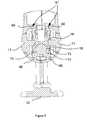
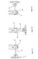
- FIG. 22is a schematic side view of a further embodiment of a support system in accordance with the invention.
- FIG. 23shows the support system of FIG. 22 from the front
- FIG. 24is a schematic side cross-sectional view of the devices of FIGS. 22 and 23 .
- a support device 1includes a table securing element 2 , a lower arm 3 , upper arm 4 , monitor mounting head and pivot 5 , and a monitor plate 6 for securing to the back of a monitor to be supported (not shown).
- the table securing element 2has a screw or clamp arrangement for removably securing the element 2 to a table or other surface and an upstanding pin 7 received within a corresponding hole 8 in the end of the lower arm 3 such that the lower arm 3 can rotate about a vertical Y′ axis (see FIG. 1 ) relative to the table securing element 2 .
- the lower arm 3then has a hole or female coupling 9 at its upper end to receive a pin or male coupling 10 at the bottom end of the upper arm 4 .
- the upper arm 4can rotate about a vertical axis Y′′ (see FIG. 1 ) relative to the lower arm 3 by virtue of this pin and hole engagement.
- the lower arm 3can rotate relative to the table securing element 2 about a vertical axis Y′
- the upper arm 4can rotate relative to the lower arm 3 about a vertical axis Y′′ and a horizontal axis X′′
- the mounting head 5can rotate relative to the distal end of the upper support arm 4 about two orthogonal axes (one substantially horizontal axis X′′′ and the other substantially vertical axis Y′′′).
- the monitor supporting head 5can also rotate about a horizontal axis Z′′′ orthogonal to the X′′′ and Y′′′ axes.
- the mounting head 5comprises a movement joint hoop 11 with a fixing portion 12 for slidable engagement with the monitor supporting plate 6 , and an elongate curved member, arc or hoop segment 13 of substantially circular cross-section.
- a motion joint 14 with an internal circular bearing surface 15 corresponding to the circumference of the curved member 13is positioned on the curved member 13 and can move along the hoop segment or curved member 13 and rotate around the hoop segment.
- the motion joint 14is a two-part plastics moulding. The plastics moulding is held between two projecting portions 16 at the distal end of the upper support arm 4 . Slotted screws 17 apply pressure to the outside of each side of the moulding via rectangular nuts and Belleville washers 18 so that the motion joint is frictionally engaged on the hoop.
- the projecting arms 16can rotate relative to the motion joint 14 such that the support arm can rotate about horizontal axis X′′′. Projecting portions 60 on the inside of the upper arm projections 16 engage a track 61 on the motion joint 14 to allow this relative rotation about axis X′′′.
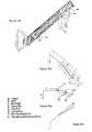
- the support device 1includes movement joint hoop 11 , distal front link pivot pin 19 , proximal front link pivot pin 42 , motion joint moulding left half 20 , motion joint adjustment screws 17 , Belleville washers 18 , front link 21 , thin hex nut 22 , mid joint button screws 23 , upper arm casting left half 24 , spring slider moulding left half 25 , friction pad 26 , anti-finger trap moulding 27 , power link 28 , mid joint pivot pin 29 , force adjustment screw 30 , mid joint 31 , steel washer 32 , spring slider moulding right half 34 , compression spring 35 , head screw 36 , upper arm casting right half 37 , rectangular nuts 38 , motion joint moulding right half 39 , spring nut plate 40 and cable management clip 41 .
- the motion joint 14can move relative to the curved member 13 .
- This expressionrefers to relative movement in a direction along the curvature of the curved member 13 and includes movement of the motion joint with the hoop remaining still, movement of the hoop with the motion joint remaining still and movement of both the motion joint and hoop.
- the curved member 13lies on the circumference of a circle whose centre lies at or near the centre of gravity of the monitor or other element being supported on the mounting head. This reduces the magnitude of the frictional force which the bearing surfaces 15 of the motion joint must apply to the surface of the curved member 13 in order to hold its position on the hoop.
- the motion joint 14can also rotate relative to the curved member 13 and a combination of the movement along and about the curved member 13 means that, for example, a monitor (not shown) on the mounting head 5 , can be rotated about orthogonal X′′′ and Y′′′ axes.
- the mount fixing portion 12is held in a turntable like portion of the monitor supporting plate 6 such that the monitor supporting plate 6 can rotate relative to the mount fixing portion 12 about axis Z′′ (see FIG. 1 ).
- the upper support arm 4is a two-part metal casting whose two halves 24 , 37 are held together by a screw and nut coupling 36 , 22 towards the distal end of the upper support arm and a pair of proximal mid-joint button screws 23 which each pass through a pair of holes in the upper end of the mid joint 31 and engage opposite ends of the mid joint pivot pin 29 so that the upper support arm 4 can pivot about that mid joint pivot pin 29 and hence about horizontal axis X′′ (see FIG. 1 ).
- the distal end of each half of the upper support end casingforms one half 16 of a U-shaped motion joint fixing portion so that together the two halves of the casting capture the motion joint 14 as described above (see FIGS. 8 and 9 ).
- An upper support arm front link 21is mounted at its distal end on the distal front link pivot 19 held between the two halves 20 , 39 of the motion joint 14 and at its proximal end on a proximal front link pivot pin 42 pivotally mounted on the distal end of a sliding carriageway or spring slider 43 supported within the upper arm casing.
- the spring slider 43is a two-part moulding 25 , 34 and the proximal front link pivot pin 42 is held between the distal ends of the two halves to support the front link 21 .
- the slider 43moves along the longitudinal axis L of the support arm 4 without a component of movement perpendicular thereto.
- the described embodimentshave the spring slider 43 inside the support arm; it could also be arranged around or alongside the upper support arm 4 provided that it moves along or parallel to the longitudinal axis L of the upper support arm 4 with no significant component of movement perpendicular thereto.
- the spring slider 43has a compression spring 35 (not shown in FIGS. 12 a to 12 c ) inside it which engages at its distal end with a spring nut plate 40 mounted on the distal end of a force adjusting screw 30 .
- the force adjustment screwis set to define a particular separation between the spring nut plate 40 and the proximal end of the spring slider 43 . This defines the length of the space for the compression spring 35 and hence determines the force supplied by the spring 35 .
- the force adjusting screw 30can adjust the position of the spring nut plate 40 within the spring slider moulding and thereby increase or decrease the length of the compression spring and hence, respectively, decrease or increase the force that spring will apply to the spring slider and spring nut plate, and hence to the rear power link 28 pivotally connected to the proximal end of the spring slider 43 against which the proximal end of the spring 35 acts.
- the rear power link 28is arranged between the proximal end of the spring slider 43 and the mid-joint 31 so as to transmit the force from the compression spring 35 to the mid-joint 31 .
- the rear power link 28is connected to the spring slider 43 at the rear power link's distal end by a distal rear link pivot pin 44 held between the two moulding halves 25 , 34 of the spring slider 43 and is connected to the mid-joint 31 by a proximal rear link pivot pin 45 held between two upstanding portions 46 of the U-shaped mid-joint 31 .
- the rear power link proximal pivot 45is located on the mid-joint below the upper arm pivot point 29 and at a position forward or distal from the vertical axis passing through that support arm pivot point 29 .
- the combination of the support arm outer casing 47 pivotally coupled at its proximal end to the mid-joint 31 and at its distal end to the motion joint 14 , combined with the internal slider 43 coupled at its distal end via the front link 21 and at its proximal end via the rear power link 28means that a monitor supported on the mounting head remains in substantially the same plane as the upper support arm 4 pivots about the mid-joint 31 in the manner shown in FIGS. 12 a , 12 b and 12 c.
- the rear power link 28pushes the slider 43 in the support arm casing 47 towards the motion joint 14 . This then causes the front link 21 to push its pivot point on the motion joint forward.
- Slider 43can slide freely along support arm casing 47 , along the centre or longitudinal axis L of the bar or force adjustment screw 30 .
- the slider 43is inside the support arm casing 47 but it is also possible to have the slider 43 and associated links and pivots arranged outside and around the casing 47 .
- the upper support armmoves through its range of motion (for example, in direction A from about 40° above the horizontal, as shown in FIG. 2 a to about 40° below the horizontal as shown in FIG. 12 c )
- slider 43slides along and relative to the arm casing 47 at a certain rate (i.e. distance along arm casing per degree of rotation).
- This sliding rateis defined by the geometry of the rear power link 28 , the position of the proximal rear link pivot pin 45 relative to the mid-joint pivot pin 29 , and the position of distal rear link pivot 44 relative to the centre longitudinal axis of the bar 30 .
- the rotation in direction Bis at a defined rate (i.e. angle of rotation per measure of distance moved by slider 43 along the central axis of the arm).
- This rate of rotationis defined by the geometry of the front link 21 , the front link distal pivot 19 , the pivot X′′′ (see FIG. 1 ) and the front link proximal pivot 42 relative to the centre axis L.
- ddistance between mid-joint pivot 29 and proximal force transmission link pivot 45
- zangle to vertical of the straight line between mid-joint pivot 29 and proximal force transmission link pivot 45
- edistance along perpendicular line from (longitudinal axis of support arm) to distal pivot 44 of proximal link 28
- glength of proximal force transmission link 28 between its respective pivots
- Idistance between proximal and distal support arm pivots 29 , X′′′
- ncomponent along support arm longitudinal axis between proximal pivot 42 of distal link 21 and distal pivot 44 of proximal link 28
- odistance along perpendicular line from (longitudinal axis of
- Kspring constant, are all constant as the upper support arm 4 pivots about pivot pin 29 ; the values of x, y, a, Spring D, p, f, B 1 , B 2 , angle C and (not shown in FIGS.
- pivots 42 and 44will move at the same rate which, as discussed above, is defined by the geometry of the rear power link 28 , proximal rear link pivot 45 , mid-joint pivot 29 , distal rear link pivot 44 and the centre line through the slider 43 , support arm casing 47 and axis L of the bar 30 (along which all three move relative to each other).
- front link 21converts this sliding action to a rotation in direct B about axis X′′′ (see FIGS. 1 and 12 a to 12 c ).
- the aimis to keep angle T (see FIGS. 13 e and 13 f ) constant or almost constant so that, for example, a monitor on the mounting head is at the same angle as the arm is rotated.
- angle Tis selected so that the monitor tilts 5 degrees upwards as this allows for any tolerances/variations in the assembly of the support arm.
- the market perception of a monitor armis better if the screen points up slightly rather than points down (as this gives the impression of drooping).
- the upper support arm 4in order to raise and/or lower a monitor (not shown) fixed to the mounting head 14 relative to the lower arm 3 and hence the table surface on which the support device 1 is mounted, the upper support arm 4 can be rotated from its highest position (see FIG. 12 a ), approximately 45 degrees above the horizontal down to its lowest position (see FIG. 11 c ), approximately 45 degrees below the horizontal.
- the spring 35 inside the support arm 4acts on the mid-joint 31 via the rear link 28 to produce a torque which counter-acts the torque produced by the weight of the monitor.
- the distance of the monitor from its centre of gravity to the mid-joint pivot Pis at its greatest when the upper support arm is horizontal ( FIG. 14 b ) and at its lowest when the monitor is in either its uppermost ( FIG. 14 a ) or lowermost ( FIG. 14 c ) positions.
- the torque at the mid joint pivot 29 (P in FIGS. 14 and 16 ) created by the monitor weightis at a maximum when the arm angle to the horizontal is 0° and at a minimum at the ends of its range of movement which are +45° and ⁇ 45° in the illustrated example.
- the graph of FIG. 15is an illustration of the magnitude of the torque at P (i.e. pivot point 29 ) created by a monitor weight which assumes a monitor weight of 40N, an arm length of 265 mm and a range of movement of +/ ⁇ 45° from the horizontal.
- the known arrangements (see FIG. 16 ) for opposing the torque created at the pivot point 29 by the load at the distal end of the support armuse a spring force G created by either a mechanical spring or gas spring inside the upper support arm 4 .
- This spring force Gis transmitted via a rear power link 51 of length f which acts through proximal rear link pivot point 52 at a distance d vertically below the main support arm pivot point P (or 29 ).
- the torque T at P generated by the spring force Gis the product of the force S in the rear link 51 and the distance d. Force S is equal to the component of spring force G along the direction of the rear power link.
- the variation in Tis as shown in FIG. 17 by the constant force line 65 .
- the torque Tvaries as the support arm pivots because the component of the spring force G along the direction of the rear power link 51 varies as this pivots relative to the upper support and the direction of the spring force G.
- the torque created by the constant spring force in the known arrangement of FIG. 16does not vary in the same way as the torque created by the weight of the load W (line 66 in graph).
- the peak weight opposing torque 62i.e.
- the torque produced by the spring force Gis not at the same position as the peak torque created by the load weight. Furthermore, if the spring force is created by a mechanical spring such as a compression spring, the differences are even greater (see FIG. 18 wherein the variation in torque from a compression spring is line 67 )). This is because the magnitude of the spring force G varies as the spring is compressed to varying degrees as the upper support arm rotates.
- the torque produced by the weight of the monitor(see FIGS. 19 and 20 ) is opposed by a torque which is the product of the spring force created by the compression spring 35 in the rear power link 28 and the perpendicular distance e between the line of that force and the proximal power link pivot 45 .
- FIGS. 13 a to 13 g and 20 a to 20 care identical to FIGS. 13 a to 13 g and 20 a to 20 c :
- Kspring constant
- Frictionacts at two main points: between the slider 43 and outer casing 47 and also at the mid-joint 29 . Increased spring load leads to increased friction but it is not necessary to precisely determine the exact friction levels as frication is used as an aid to provide a degree of tolerances to the functioning system.
- the inventors of the subject inventionhave appreciated that it is possible to match the torque created by the spring force of a spring within the support arm to the torque created by a load weight without the use of a cam such as used in the prior art by careful selection of the arm geometry and that a support arm with a slider moveable along its centre axis with rear and front link pivots combined with the freedom to locate the rear link proximal pivot 45 of a point other than vertically below the support arm proximal pivot 29 allows for the selection of a geometry loading to a sufficiently close match.
- frictional forcesmeans that a perfect match is not necessary and that the standard construction with a rear link power pivot vertically underneath the main support arm proximal pivot was sub-optimal.
- the selection of the support arm geometryis done by a targeted graphical method.
- the torque about pivot 29is determined for different support arm positions and plotted as a graph similar to that of FIG. 15 .
- the counter-balancing torqueis given by equation 11. Values for each of the relevant constant (i.e. constant as the arm rotates) parameters are selected iteratively limited by the range of values of each which are possible and appropriate for the arm's function and aesthetics. Each set of those selected values is input into equations 7 to 11 for a series of different values of the angle x (and hence of other variable angles and lengths which vary as the arm rotates) to generate a graph similar to that of FIG. 21 .
- the fixed or constant valuesi.e.
- the illustrated embodiment of the inventionhas a force adjustment screw 30 which can pre-stress the spring 30 which can pre-stress the spring 35 to a different extent and thereby also affect the torque about pivot 29 resulting from the spring force.
- the matching exercise described aboveis therefore repeated for a number (say 4) of different pre-stresses which would correspond to different monitor weights or loads as a check that a selected geometry can also match different loads and degrees of appropriate pre-stressing of the spring 35 .
- equations 1 to 6are used to plot a graph of T and the same iterative process is used to find geometry values for which T remains roughly constant during the range of movement of the arm. This may require some modification of the values determined by the first stage of iteration so it may be necessary to repeat that first process of matching torque lines or a graph until a geometry which best matches the twin requirements of constant T and matching torque w is achieved.
- the proximal rear power link pivot pin 44 of the described embodiment of the inventionis located forward (or distal) from the axis W (see FIG. 19 b ) through the mid-joint pivot 29 which is orthogonal to the longitudinal axis of the upper support arm at the mid point of range of movement of the upper support arm; i.e. the proximal rear link pivot 44 is forward of a vertical axis through the mid-joint pivot 29 when the upper support arm can move between +/ ⁇ 45° to the horizontal.
- the inventorshave determined that locating the rear power link pivot pin 44 forward or back from the vertical through the mid-joint pivot 29 allows for a better match of the torque exerted by the spring force about the pivot 29 to the torque exerted by the weight of a load on the mounting head 14 as the support arm moves through its range of motion.
- proximal pivot 45 for the rear linkat a position forward or distal from the vertical line through the proximal support arm pivot 29 (i.e. forward or distal from the line or axis along which gravity acts means that the perpendicular distance e varies in a manner which is closer to the variation in the torque caused by the weight of the monitor than is the case in the known arrangements which have the rear link pivot point in line with a vertical line through the proximal support arm pivot.
- FIGS. 19 a to 19 cas the support arm 4 rotates from its uppermost position (see FIG. 19 a ), through the mid-position (see FIG. 19 b ) down to its lowermost position ( 19 c ), the rear power link 28 progressively compresses the spring 35 by pushing it against the fixed spring nut plate 40 . This means that the force provided by the spring 35 progressively increases as the support arm 4 is lowered in a manner similar to that discussed above in connection with FIG. 18 .
- FIGS. 22 to 24A support system utilising the invention intended for these circumstance is shown schematically in FIGS. 22 to 24 .
- FIGS. 22 to 24differs from those described above in that the support arm and hoop element are replaced by a single curved arm 100 which is of circular cross-section along its entire operative length.
- the curved arm 100cooperates with a motion joint 102 generally similar to motion joint 14 described above.
- motion joint 102in particular, the internal bearing surface which engages the external surface of the curved arm 100 , are the same as those of motion joint 14 , but the external casing 104 of the motion joint 102 is designed to allow it to be mounted securely in a through opening formed in, as shown in the drawings, a generally horizontal surface such as a tabletop 106 .
- the outer casing 104may be formed in two parts, each provided with an outwardly-extending annular flange, so that when the two parts of the casing 104 are secured together, the margin of the tabletop 106 around the through opening is trapped between the flanges to secure the casing 104 in the through opening.
- the casing 104may be secured by other means such as gluing.
- FIGS. 22 to 24show the support system being used to mount a display device 101 relative to a generally horizontal surface, it will be understood that a similar arrangement may be used in respect of generally vertical surfaces such as walls or, indeed, in relation to inclined surfaces.
- the display device 101is secured to the curved arm 100 by means of a suitable mounting plate 108 . Whilst this may serve simply to hold the display device 101 on the end of the curved arm 100 in a fixed position, the mounting plate 108 preferably includes a bearing 110 so that the display device 101 can be rotated at will about the end of the circular-section curved arm 100 . This not only allows fine adjustment of the viewing position of the display device 101 in use but also facilitates stowing of the display device 101 neatly against the tabletop 106 or in a recess, where one is provided, when it is no longer needed.
- the end of the curved arm 100 remote from the display device 101is provided with an end cap 112 of larger diameter than the curved arm 100 which acts as a stop to prevent the curved arm 100 being drawn all the way through and removed from the motion joint 102 .
- the curved arm 100can be moved through the motion joint 102 , overcoming the friction exerted by the internal bearing surface, until the display device 101 is a suitable distance from the surface of the tabletop 106 .
- the frictional engagement of the internal bearing surface with the cylindrical surface of the curved arm 100will then prevent the arm 100 sliding back through the motion joint 102 .
- the position and orientation of the display devicecan then be adjusted further either by rotation of the curved arm 100 about its axis within the internal bearing surface of the motion joint 102 or by rotation mounting plate 108 of the display device 101 about the central axis of the end of the curved arm 100 , or both.
- the curved arm 100can be hollow so that cables can be fed through it.
Landscapes
- Engineering & Computer Science (AREA)
- General Engineering & Computer Science (AREA)
- Mechanical Engineering (AREA)
- Microelectronics & Electronic Packaging (AREA)
- Manipulator (AREA)
- Transmission Devices (AREA)
Abstract
Description
This application is the National Stage of International Application PCT/GB2011/000874, filed Jun. 9, 2011, which was a continuation-in-part of U.S. patent application Ser. No. 13/024,685, filed Feb. 10, 2011, the entire disclosure of which is hereby incorporated herein by reference.
The present invention is concerned with a support system. Particular embodiments of the invention are concerned with a moveable support arm for a monitor or display device.
Modern screen-based display devices are typically flat-screen monitors such as liquid crystal display (LCD) or plasma screen displays. Such devices can be mounted on elevated support devices such as a support arm which can then be secured to a surface such that the flat-screen monitor is held above or in front of the surface.
Support systems for monitors are known which allow for movement in three dimensions of the head, mount or bracket on which the monitor is mounted. This is so as to allow for a full range of adjustment of the monitor.GB 2 438 581 and U.S. Pat. No. 7,438,269 both disclose mounts or brackets including an arcuate connection which allows a monitor to be pivoted about a substantially horizontal virtual pivot axis. In U.S. Pat. No. 7,438,260 the virtual pivot axis passes through the centre of gravity of a monitor or display so as to reduce the forces necessary to hold the mount in place at a selected position on the arcuate connection.
In order to allow for adjustment about a substantially vertical axis (or an axis orthogonal to the axis of the arcuate connection), known arrangements such as those disclosed inGB 2 438 581 and U.S. Pat. No. 7,438,269 have a second pivoting mechanism entirely separate from the first. The second pivot is a separate vertical rod-like element defining a vertical axis. This second pivot is distinct and separated from the pivot of the arcuate connector.
These prior art arrangements require two separate and distinct pivot arrangements. They are therefore relatively complicated and expensive to build, have two pivots (and therefore more moving parts) which can fail and are relatively unsightly.
The present invention, in its first aspect, provides a single simple mechanism which allows a full range of adjustment of a load in three orthogonal directions (i.e. about orthogonal X, Y and Z axes). This mechanism is easier and cheaper to make than the know arrangements and is aesthetically more pleasing.
Support systems for monitors comprising an articulated arm arrangement for raising and lowering a monitor are known with tiltable mount or bracket mechanisms which keep the monitor in the same plane as the arm moves up and down. The known arrangements such as those disclosed in US 2004/0245419 have a four bar linkage or parallelogram arrangement in which there is a second link or arm below (or above) and parallel to the main support arm and pivotally coupled to the tiltable mount or bracket on which a monitor is mounted. The second link or arm is pivotally coupled to the mount or bracket below (or above) the pivot between the main support arm and the mount, and also pivotally coupled to the base or support element to which the other end of the main support arm is pivotally coupled at a point below (or above) the pivot between the main support arm and the base or support element. The main support arm and the second link arm are parallel to each other and the linkage (which can be considered to be a line drawn between) the pairs of pivots on each of the base element and mount are also parallel to each other.
This parallelogram four-bar linkage means that as the support arm is moved up and down the linkage between the two pivots on the tilt mount remains in the same plane parallel to the linkage between the two pivots on the base element.
A disadvantage of the known four-bar parallelogram linkage arrangements is the need to provide a second link parallel to and separate from the support arm. Such arrangements therefore must have a second visible (and therefore unsightly) link or arm parallel to the main support arm. Alternatively, such parallelogram arrangements have a large deep casing which can house the main support arm, the second parallel link and the space therebetween. This is bulky and therefore also unsightly.
The support system of the present invention in its second aspect eliminates the need for a second parallel link separated from the first and a vertical separation between the two parallel links. The present invention in its second aspect therefore allows for a more compact and aesthetically pleasing support arm which keeps its load mount in the same plane as the support arm moves up and down.
The use of a slider element moveable along the longitudinal axis of the support arm (without a component of movement orthogonal or perpendicular thereto) allows for an aesthetically pleasing structure without a second visible arm with a component of movement both along and perpendicular to the support arm.
A problem with articulated support arms for loads such as monitors or display devices which move up and down as they pivot about a horizontal axis, is the varying torque created by the constant weight of the monitor applied about the horizontal axis. As the arm moves up and down the distance from the load at the end of the support arm to the other end of the support arm and the pivot between the support arm and its base varies. The maximum distance and hence torque is when the arm is horizontal (seeFIGS. 12 band14b) and at its minimum when in its uppermost (seeFIGS. 12 aand14a) and lowermost (seeFIGS. 12 cand14c) positions.
In order to oppose this varying torque it is known (see, for example, US 2004/0245419) to provide a compression spring which provides a variable force to create a torque to oppose and match the torque created by the weight of the load. The spring is subject to a cam arrangement which controls the degree of compression of the spring and hence the force it applies.
Cam arrangements of the type disclosed in US 2004/0245419 are relatively complex and hence expensive to make.
The present invention in its third aspect provides an arrangement for varying the torque applied to oppose the variations in torque resulting as the support arm is pivoted about a horizontal axis.
The invention in its third aspect provides a mechanism which allows the variations in torque provided by the force generating member as the support arm pivots and which opposes the weight of a load on the support arm to better match the variations in torque provided by the weight as the support arm pivots. The inventors of the subject application are the first to realise that taking the step of moving the proximal force transmission link pivot away from its usual position on the line vertically through the proximal support arm pivot and substantially orthogonal to the longitudinal axis of the support arm when this is at the mid-point of its range of movement about the proximal support arm pivot allows one to better match the shape of the graphs of variation in supporting torque and load weight torque with support arm movement to each other and hence better support a load on the support arm. The inventors are the first to appreciate that the counter-intuitive step of moving away from the essentially symmetrical proximal support arm pivot and proximal force transmission pivot arrangement of the prior art actually allows one to produce a more symmetrical variation in supporting torque to better match load weight torque.
The invention in its fourth aspect provides a method of designing a support system. The inventors have appreciated that it is possible to provide an aesthetically pleasing support system which does not require a complicated arrangement to match its variations in torque caused by a load on the system as it moves through its range of movement by careful selection of the dimensions and geometry of that system. Preferred embodiments of the present invention will now be described, by way of non-limiting example only, with reference to the attached figures. The figures are only for the purposes of explaining and illustrating preferred embodiments of the invention and are not to be construed as limiting the claims. The skilled man will readily and easily envisage alternative embodiments of the invention in its various aspects.
In the figures:
Referring toFIGS. 1 to 3 , asupport device 1 includes atable securing element 2, alower arm 3,upper arm 4, monitor mounting head andpivot 5, and amonitor plate 6 for securing to the back of a monitor to be supported (not shown). Thetable securing element 2 has a screw or clamp arrangement for removably securing theelement 2 to a table or other surface and an upstanding pin7 received within acorresponding hole 8 in the end of thelower arm 3 such that thelower arm 3 can rotate about a vertical Y′ axis (seeFIG. 1 ) relative to thetable securing element 2. Thelower arm 3 then has a hole orfemale coupling 9 at its upper end to receive a pin ormale coupling 10 at the bottom end of theupper arm 4. Theupper arm 4 can rotate about a vertical axis Y″ (seeFIG. 1 ) relative to thelower arm 3 by virtue of this pin and hole engagement.
Referring toFIG. 1 , thelower arm 3 can rotate relative to thetable securing element 2 about a vertical axis Y′, theupper arm 4 can rotate relative to thelower arm 3 about a vertical axis Y″ and a horizontal axis X″, and (as discussed in more detail below) the mountinghead 5 can rotate relative to the distal end of theupper support arm 4 about two orthogonal axes (one substantially horizontal axis X′″ and the other substantially vertical axis Y′″). Themonitor supporting head 5 can also rotate about a horizontal axis Z′″ orthogonal to the X′″ and Y′″ axes.
Referring toFIGS. 5 to 8 , the mountinghead 5 comprises a movementjoint hoop 11 with a fixingportion 12 for slidable engagement with themonitor supporting plate 6, and an elongate curved member, arc orhoop segment 13 of substantially circular cross-section. A motion joint14 with an internalcircular bearing surface 15 corresponding to the circumference of thecurved member 13 is positioned on thecurved member 13 and can move along the hoop segment orcurved member 13 and rotate around the hoop segment. The motion joint14 is a two-part plastics moulding. The plastics moulding is held between two projectingportions 16 at the distal end of theupper support arm 4. Slotted screws17 apply pressure to the outside of each side of the moulding via rectangular nuts andBelleville washers 18 so that the motion joint is frictionally engaged on the hoop.
The projectingarms 16 can rotate relative to the motion joint14 such that the support arm can rotate about horizontal axis X′″. Projectingportions 60 on the inside of theupper arm projections 16 engage atrack 61 on the motion joint14 to allow this relative rotation about axis X′″.
Referring toFIG. 5 , thesupport device 1 includes movementjoint hoop 11, distal frontlink pivot pin 19, proximal frontlink pivot pin 42, motion joint moulding lefthalf 20, motion joint adjustment screws17,Belleville washers 18,front link 21,thin hex nut 22, mid joint button screws23, upper arm casting lefthalf 24, spring slider moulding lefthalf 25,friction pad 26,anti-finger trap moulding 27,power link 28, midjoint pivot pin 29,force adjustment screw 30, mid joint31,steel washer 32, spring slider moulding righthalf 34,compression spring 35,head screw 36, upper arm castingright half 37,rectangular nuts 38, motion joint mouldingright half 39,spring nut plate 40 andcable management clip 41.
As illustrated inFIGS. 10 aand10b, the motion joint14 can move relative to thecurved member 13. In this application we will usually refer to movement of the motion joint along the hoop or hoop segment. This expression refers to relative movement in a direction along the curvature of thecurved member 13 and includes movement of the motion joint with the hoop remaining still, movement of the hoop with the motion joint remaining still and movement of both the motion joint and hoop.
In a particularly preferred embodiment of the invention, thecurved member 13 lies on the circumference of a circle whose centre lies at or near the centre of gravity of the monitor or other element being supported on the mounting head. This reduces the magnitude of the frictional force which the bearing surfaces15 of the motion joint must apply to the surface of thecurved member 13 in order to hold its position on the hoop. As illustrated inFIGS. 11 ato11c, the motion joint14 can also rotate relative to thecurved member 13 and a combination of the movement along and about thecurved member 13 means that, for example, a monitor (not shown) on the mountinghead 5, can be rotated about orthogonal X′″ and Y′″ axes. In this application we usually refer to rotation of the motion joint about the hoop. This expression refers to relative rotation about a curved axis running down the middle of thecurved member 13 and includes rotation of the motion joint with the hoop remaining still, rotation of the hoop with the motion joint remaining still and rotation of both the motion joint and hoop.
Themount fixing portion 12 is held in a turntable like portion of themonitor supporting plate 6 such that themonitor supporting plate 6 can rotate relative to themount fixing portion 12 about axis Z″ (seeFIG. 1 ).
Theupper support arm 4 is a two-part metal casting whose twohalves nut coupling joint pivot pin 29 so that theupper support arm 4 can pivot about that midjoint pivot pin 29 and hence about horizontal axis X″ (seeFIG. 1 ). The distal end of each half of the upper support end casing forms onehalf 16 of a U-shaped motion joint fixing portion so that together the two halves of the casting capture the motion joint14 as described above (seeFIGS. 8 and 9 ). An upper supportarm front link 21 is mounted at its distal end on the distalfront link pivot 19 held between the twohalves link pivot pin 42 pivotally mounted on the distal end of a sliding carriageway orspring slider 43 supported within the upper arm casing. Thespring slider 43 is a two-part moulding link pivot pin 42 is held between the distal ends of the two halves to support thefront link 21. When the device is assembled, theslider 43 moves along the longitudinal axis L of thesupport arm 4 without a component of movement perpendicular thereto. The described embodiments have thespring slider 43 inside the support arm; it could also be arranged around or alongside theupper support arm 4 provided that it moves along or parallel to the longitudinal axis L of theupper support arm 4 with no significant component of movement perpendicular thereto.
Thespring slider 43 has a compression spring35 (not shown inFIGS. 12 ato12c) inside it which engages at its distal end with aspring nut plate 40 mounted on the distal end of aforce adjusting screw 30. At initial set up or final manufacture of thesupport device 1, the force adjustment screw is set to define a particular separation between thespring nut plate 40 and the proximal end of thespring slider 43. This defines the length of the space for thecompression spring 35 and hence determines the force supplied by thespring 35. Theforce adjusting screw 30 can adjust the position of thespring nut plate 40 within the spring slider moulding and thereby increase or decrease the length of the compression spring and hence, respectively, decrease or increase the force that spring will apply to the spring slider and spring nut plate, and hence to therear power link 28 pivotally connected to the proximal end of thespring slider 43 against which the proximal end of thespring 35 acts.
Therear power link 28 is arranged between the proximal end of thespring slider 43 and the mid-joint31 so as to transmit the force from thecompression spring 35 to the mid-joint31. Therear power link 28 is connected to thespring slider 43 at the rear power link's distal end by a distal rearlink pivot pin 44 held between the twomoulding halves spring slider 43 and is connected to the mid-joint31 by a proximal rearlink pivot pin 45 held between twoupstanding portions 46 of theU-shaped mid-joint 31. The rear power linkproximal pivot 45 is located on the mid-joint below the upperarm pivot point 29 and at a position forward or distal from the vertical axis passing through that supportarm pivot point 29.
As will be discussed in more detail below, the combination of the support armouter casing 47 pivotally coupled at its proximal end to the mid-joint31 and at its distal end to the motion joint14, combined with theinternal slider 43 coupled at its distal end via thefront link 21 and at its proximal end via therear power link 28 means that a monitor supported on the mounting head remains in substantially the same plane as theupper support arm 4 pivots about the mid-joint31 in the manner shown inFIGS. 12 a,12band12c.
Referring toFIGS. 12 ato12c, as the upper support arm pivots about the mid-joint pivot pin in direction A from, for example, the position shown inFIG. 12 ato the position shown inFIG. 12 b(or, for example, the position shown inFIG. 12 bto the position inFIG. 12 c), therear power link 28 pushes theslider 43 in thesupport arm casing 47 towards the motion joint14. This then causes thefront link 21 to push its pivot point on the motion joint forward. As the distal frontlink pivot pin 19 is located on the motion joint14 at a point below the pivot or axis of rotation X′″ between the motion joint14 and the support armouter casing 47, this causes the motion joint14 to rotate in direction B relative to thesupport arm casing 47 and thereby reduce or prevent tilting of the monitor relative to its original plane. If there were no movement of the motion joint in direction B relative to the support casing, a monitor held on the mounting head would tilt in direction C as the support arm was rotated in direction A.
Referring toFIGS. 13 ato13g, the distances or values d, z, e, g, I, n, o, offset, m, j. In length and k, d—distance between mid-joint pivot29 and proximal force transmission link pivot45; z—angle to vertical of the straight line between mid-joint pivot29 and proximal force transmission link pivot45; e—distance along perpendicular line from (longitudinal axis of support arm) to distal pivot44 of proximal link28; g—length of proximal force transmission link28 between its respective pivots; I—distance between proximal and distal support arm pivots29, X′″; n—component along support arm longitudinal axis between proximal pivot42 of distal link21 and distal pivot44 of proximal link28; o—distance along perpendicular line from (longitudinal axis of support arm) to proximal pivot42 of distal link21; offset—the perpendicular distance of the pivot point of the motion head from the longitudinal axis; m—the parallel distance between the pivot point of the motion head and the pivot point19; j—length of distal link21 between its respective pivots19,42; In length—free spring length (i.e. length of unloaded spring); K—spring constant, are all constant as the upper support arm4 pivots about pivot pin29; the values of x, y, a, Spring D, p, f, B1, B2, angle C and (not shown inFIGS. 13 ato13g) Spring force W, x—angle between longitudinal axis of arm and vertical; y—angle between longitudinal axis of arm and line between the pivots of the force transmission link28; a—distance along longitudinal axis of arm between link distal pivot44 and mid-joint pivot29; Spring D—stressed spring length; p—distance along longitudinal axis of arm between distal link proximal pivot44 and mounting head pivot X′″; f—parallel distance between pivot42 and cross-section between centre line of motion joint surface15 and vertical line motion head; B1—angle between longitudinal axis of arm and line between mounting head pivot X′″ and distal link proximal pivot43; B2—angle between line between mounting head pivot X′″ and distal link proximal pivot43, and line between mounting head pivot X′″ and distal link distal pivot19; T—tilt angle (angle between line between vertical and line between mounting head pivot X′″ and distal link distal pivot19; angle C—angle between line between mounting head pivot X′″ and distal link distal pivot19, and line between the pivots19,42 of the distal link21), however vary as the arm47 rotates or pivots about pivot29, thorough angle x.
As theslider 43 holds distalrear link pivot 44 and proximal front link pivot42 a fixed distance or apart, pivots42 and44 will move at the same rate which, as discussed above, is defined by the geometry of therear power link 28, proximalrear link pivot 45,mid-joint pivot 29, distalrear link pivot 44 and the centre line through theslider 43,support arm casing 47 and axis L of the bar30 (along which all three move relative to each other).
Aspivot 42 moves forward at the defined rate set by the geometry of the various elements at the proximal end of theslider 43 andsupport arm casing 47,front link 21 converts this sliding action to a rotation in direct B about axis X′″ (seeFIGS. 1 and 12 ato12c).
As thearm 4 rotates, the aim is to keep angle T (seeFIGS. 13 eand13f) constant or almost constant so that, for example, a monitor on the mounting head is at the same angle as the arm is rotated. In practice the angle T is selected so that the monitor tilts 5 degrees upwards as this allows for any tolerances/variations in the assembly of the support arm. Experience also suggests that the market perception of a monitor arm is better if the screen points up slightly rather than points down (as this gives the impression of drooping).
The inter-relationship between the various parameters illustrated inFIGS. 13 ato13gis defined by the following equations;
As shown in, for example,FIGS. 1 ,12a,12band12c, in order to raise and/or lower a monitor (not shown) fixed to the mountinghead 14 relative to thelower arm 3 and hence the table surface on which thesupport device 1 is mounted, theupper support arm 4 can be rotated from its highest position (seeFIG. 12 a), approximately 45 degrees above the horizontal down to its lowest position (seeFIG. 11 c), approximately 45 degrees below the horizontal. Thespring 35 inside thesupport arm 4 acts on the mid-joint31 via therear link 28 to produce a torque which counter-acts the torque produced by the weight of the monitor.
As can be seen fromFIG. 14 , the distance of the monitor from its centre of gravity to the mid-joint pivot P, is at its greatest when the upper support arm is horizontal (FIG. 14 b) and at its lowest when the monitor is in either its uppermost (FIG. 14 a) or lowermost (FIG. 14 c) positions.
This means that (as shown inFIG. 15 ) the torque at the mid joint pivot29 (P inFIGS. 14 and 16 ) created by the monitor weight is at a maximum when the arm angle to the horizontal is 0° and at a minimum at the ends of its range of movement which are +45° and −45° in the illustrated example. The graph ofFIG. 15 is an illustration of the magnitude of the torque at P (i.e. pivot point29) created by a monitor weight which assumes a monitor weight of 40N, an arm length of 265 mm and a range of movement of +/−45° from the horizontal.
The known arrangements (seeFIG. 16 ) for opposing the torque created at thepivot point 29 by the load at the distal end of the support arm use a spring force G created by either a mechanical spring or gas spring inside theupper support arm 4. This spring force G is transmitted via arear power link 51 of length f which acts through proximal rearlink pivot point 52 at a distance d vertically below the main support arm pivot point P (or29). The torque T at P generated by the spring force G is the product of the force S in therear link 51 and the distance d. Force S is equal to the component of spring force G along the direction of the rear power link.
Referring toFIG. 17 , if the spring force G is constant and the range of movement of the support arm is +/−45° from the horizontal, then the variation in T is as shown inFIG. 17 by theconstant force line 65. The torque T varies as the support arm pivots because the component of the spring force G along the direction of therear power link 51 varies as this pivots relative to the upper support and the direction of the spring force G. As can be seen inFIG. 17 , the torque created by the constant spring force in the known arrangement ofFIG. 16 does not vary in the same way as the torque created by the weight of the load W (line 66 in graph). In particular, the peak weight opposing torque62 (i.e. the torque produced by the spring force G) is not at the same position as the peak torque created by the load weight. Furthermore, if the spring force is created by a mechanical spring such as a compression spring, the differences are even greater (seeFIG. 18 wherein the variation in torque from a compression spring is line67)). This is because the magnitude of the spring force G varies as the spring is compressed to varying degrees as the upper support arm rotates.
In the embodiment of the invention shown inFIGS. 1 to 11 and18, the torque produced by the weight of the monitor (seeFIGS. 19 and 20 ) is opposed by a torque which is the product of the spring force created by thecompression spring 35 in therear power link 28 and the perpendicular distance e between the line of that force and the proximalpower link pivot 45.
Referring toFIGS. 13 ato13gand20ato20c:
- where: In length=unstressed spring length (i.e. free/initial spring length)
- Spring D=stressed spring length (this is an instantaneous value as can be taken at any point in the movement)
- K=Spring constant
The torque ω at thepivot 29 resulting from that spring force is then given by
The dimensions of the support arm and its associated elements, (i.e. d—distance between mid-joint pivot29 and proximal force transmission link pivot45; z—angle to vertical of the straight line between mid-joint pivot29 and proximal force transmission link pivot45; e—distance along perpendicular line from longitudinal axis of support arm to distal pivot44 of proximal link28; g—length of proximal force transmission link28 between its respective pivots; I—distance between proximal and distal support arm pivots29, X′″; n—component along support arm longitudinal axis between proximal pivot42 of distal link21 and distal pivot44 of proximal link28; o—distance along perpendicular line from longitudinal axis of support arm to proximal pivot42 of distal link21; offset—the perpendicular distance of the pivot point of the motion head from the longitudinal axis; m—the parallel distance between the pivot point of the motion head and the pivot point19; j—length of distal link21 between its respective pivots19,42′; In length—free spring length (i.e. length of unloaded spring); K—spring constant) are selected so as to try and best match the twin objectives of keeping angle T roughly constant through the range of motion of the support arm, and of closely matching the torques about the pivot49 exerted by the weight of a load such as a monitor on the mounting head14 and that exerted by the spring force through the range of motion of the support arm. Friction acts at two main points: between theslider 43 andouter casing 47 and also at the mid-joint29. Increased spring load leads to increased friction but it is not necessary to precisely determine the exact friction levels as frication is used as an aid to provide a degree of tolerances to the functioning system.
The inventors of the subject invention have appreciated that it is possible to match the torque created by the spring force of a spring within the support arm to the torque created by a load weight without the use of a cam such as used in the prior art by careful selection of the arm geometry and that a support arm with a slider moveable along its centre axis with rear and front link pivots combined with the freedom to locate the rear linkproximal pivot 45 of a point other than vertically below the support armproximal pivot 29 allows for the selection of a geometry loading to a sufficiently close match. The inventors have appreciated that frictional forces means that a perfect match is not necessary and that the standard construction with a rear link power pivot vertically underneath the main support arm proximal pivot was sub-optimal.
The selection of the support arm geometry is done by a targeted graphical method. For a live load the torque aboutpivot 29 is determined for different support arm positions and plotted as a graph similar to that ofFIG. 15 .
The counter-balancing torque is given byequation 11. Values for each of the relevant constant (i.e. constant as the arm rotates) parameters are selected iteratively limited by the range of values of each which are possible and appropriate for the arm's function and aesthetics. Each set of those selected values is input into equations 7 to 11 for a series of different values of the angle x (and hence of other variable angles and lengths which vary as the arm rotates) to generate a graph similar to that ofFIG. 21 . The fixed or constant values (i.e. d—distance between mid-joint pivot29 and proximal force transmission link pivot45; z—angle to vertical of the straight line between mid-joint pivot29 and proximal force transmission link pivot45; e—distance along perpendicular line from longitudinal axis of support arm to distal pivot44 of proximal link28; g—length of proximal force transmission link28 between its respective pivots; I—distance between proximal and distal support arm pivots29, X′″; n—component along support arm longitudinal axis between proximal pivot42 of distal link21 and distal pivot44 of proximal link28; o—distance along perpendicular line from longitudinal axis of support arm to proximal pivot42 of distal link21; offset—the perpendicular distance of the pivot point of the motion head from the longitudinal axis; m—the parallel distance between the pivot point of the motion head and the pivot point19; j—length of distal link21 between its respective pivots19,42′; In length—free spring length (i.e. length of unloaded spring); K—spring constant) are then varied iteratively until the line on the graph of the torque generated by the spring force ofFIG. 21 closely matches the line on the graph of the torque generated by the load ofFIG. 15 .
The illustrated embodiment of the invention has aforce adjustment screw 30 which can pre-stress thespring 30 which can pre-stress thespring 35 to a different extent and thereby also affect the torque aboutpivot 29 resulting from the spring force. The matching exercise described above is therefore repeated for a number (say 4) of different pre-stresses which would correspond to different monitor weights or loads as a check that a selected geometry can also match different loads and degrees of appropriate pre-stressing of thespring 35.
Once a geometry which closely matches torque is achieved,equations 1 to 6 are used to plot a graph of T and the same iterative process is used to find geometry values for which T remains roughly constant during the range of movement of the arm. This may require some modification of the values determined by the first stage of iteration so it may be necessary to repeat that first process of matching torque lines or a graph until a geometry which best matches the twin requirements of constant T and matching torque w is achieved.
As shown inFIGS. 19 ato19c, in the described embodiment, the proximal rear powerlink pivot pin 44 of the described embodiment of the invention is located forward (or distal) from the axis W (seeFIG. 19 b) through themid-joint pivot 29 which is orthogonal to the longitudinal axis of the upper support arm at the mid point of range of movement of the upper support arm; i.e. the proximalrear link pivot 44 is forward of a vertical axis through themid-joint pivot 29 when the upper support arm can move between +/−45° to the horizontal. The inventors have determined that locating the rear powerlink pivot pin 44 forward or back from the vertical through themid-joint pivot 29 allows for a better match of the torque exerted by the spring force about thepivot 29 to the torque exerted by the weight of a load on the mountinghead 14 as the support arm moves through its range of motion.
As illustrated inFIGS. 20 and 21 whereline 68 illustrates the variation in torque created about thepivot pin 29 by thecompression spring 35 acting via therear power link 28, this position of the proximal rear powerlink pivot pin 4 moves the peak torque aboutmid-joint pivot 29 created by thespring 35 acting through therear power link 28. Careful selection of the geometry and/or dimensions of the element (and their relative geometry and dimensions) making up the proximal end of the upper support arm4 (including therear link 28; pivots29,44,45), the spring properties and the load weight allow one to move the position of peak opposing torque64 (seeFIG. 21 ) to a position closer to the position of the peak load weight torque ofline 66.
The placing of theproximal pivot 45 for the rear link at a position forward or distal from the vertical line through the proximal support arm pivot29 (i.e. forward or distal from the line or axis along which gravity acts means that the perpendicular distance e varies in a manner which is closer to the variation in the torque caused by the weight of the monitor than is the case in the known arrangements which have the rear link pivot point in line with a vertical line through the proximal support arm pivot.
Referring toFIGS. 19 ato19c, as thesupport arm 4 rotates from its uppermost position (seeFIG. 19 a), through the mid-position (seeFIG. 19 b) down to its lowermost position (19c), therear power link 28 progressively compresses thespring 35 by pushing it against the fixedspring nut plate 40. This means that the force provided by thespring 35 progressively increases as thesupport arm 4 is lowered in a manner similar to that discussed above in connection withFIG. 18 .
A further embodiment is shown inFIGS. 22-24 of the drawings.
Whilst it is usual to mount the display device on a support arm, there are some situations in which it may be desirable for the display device to be stored flat against, or in a recess so that it flush with, a surface such as a wall or table-top when it is out of use, but to be movable away from the surface to a more comfortable position for viewing when in use. A support system utilising the invention intended for these circumstance is shown schematically inFIGS. 22 to 24 .
The embodiment ofFIGS. 22 to 24 differs from those described above in that the support arm and hoop element are replaced by a singlecurved arm 100 which is of circular cross-section along its entire operative length. Thecurved arm 100 cooperates with a motion joint102 generally similar to motion joint14 described above.
The internal features of motion joint102, in particular, the internal bearing surface which engages the external surface of thecurved arm 100, are the same as those of motion joint14, but theexternal casing 104 of the motion joint102 is designed to allow it to be mounted securely in a through opening formed in, as shown in the drawings, a generally horizontal surface such as atabletop 106. For example, theouter casing 104 may be formed in two parts, each provided with an outwardly-extending annular flange, so that when the two parts of thecasing 104 are secured together, the margin of thetabletop 106 around the through opening is trapped between the flanges to secure thecasing 104 in the through opening. Alternatively, thecasing 104 may be secured by other means such as gluing.
AlthoughFIGS. 22 to 24 show the support system being used to mount adisplay device 101 relative to a generally horizontal surface, it will be understood that a similar arrangement may be used in respect of generally vertical surfaces such as walls or, indeed, in relation to inclined surfaces.
Thedisplay device 101 is secured to thecurved arm 100 by means of a suitable mountingplate 108. Whilst this may serve simply to hold thedisplay device 101 on the end of thecurved arm 100 in a fixed position, the mountingplate 108 preferably includes abearing 110 so that thedisplay device 101 can be rotated at will about the end of the circular-sectioncurved arm 100. This not only allows fine adjustment of the viewing position of thedisplay device 101 in use but also facilitates stowing of thedisplay device 101 neatly against thetabletop 106 or in a recess, where one is provided, when it is no longer needed.
The end of thecurved arm 100 remote from thedisplay device 101 is provided with anend cap 112 of larger diameter than thecurved arm 100 which acts as a stop to prevent thecurved arm 100 being drawn all the way through and removed from themotion joint 102.
In use, thecurved arm 100 can be moved through the motion joint102, overcoming the friction exerted by the internal bearing surface, until thedisplay device 101 is a suitable distance from the surface of thetabletop 106. The frictional engagement of the internal bearing surface with the cylindrical surface of thecurved arm 100 will then prevent thearm 100 sliding back through themotion joint 102. The position and orientation of the display device can then be adjusted further either by rotation of thecurved arm 100 about its axis within the internal bearing surface of the motion joint102 or byrotation mounting plate 108 of thedisplay device 101 about the central axis of the end of thecurved arm 100, or both.
When the display device is no longer needed, it can simply be returned to its original position against, or housed in a recess formed in, thetabletop 106. Thecurved arm 100 can be hollow so that cables can be fed through it.
Claims (16)
1. A support system for pivotably supporting a load comprising:
a curved member having a circular cross section; and
a motion joint slidable and rotatable relative to the curved member, wherein an outer surface of the curved member matches a bearing surface of the motion joint, wherein the motion joint and the curved member are rotatable relative to each other about a first axis extending through the curved member perpendicular to the circular cross section, and wherein the motion joint and the curved member are rotatable relative to each other about a second axis perpendicular to the first axis, the second axis located at a center of curvature of the curved member.
2. A support system according toclaim 1 wherein the curved member is provided with a mount for securing a load to the curved member.
3. A support system according toclaim 2 wherein the mount comprises a mounting plate and a joint rotatably joining the mounting plate and the curved member.
4. A support system according toclaim 1 , wherein:
the curvature of the curved member relative to the second axis is defined by a portion of the circumference of a circle; and
the motion joint further includes a support arm-mount, wherein a support arm mounted on the support arm mount is slidable along and rotatable about the first axis of the curved member.
5. A system according toclaim 4 wherein the support arm is pivotally connected to the motion joint.
6. A system according toclaim 5 further comprising a display device coupled to the curved member, the display device having a center of gravity at or near the second axis.
7. A support system according toclaim 1 having stop means provided at at least one end of the curved member to prevent complete withdrawal of the curved member through the motion joint.
8. A support system comprising:
a motion joint having an internal bearing surface; and
an elongate curved member provided with at least one axially-extending, at least part cylindrical operative surface for engaging with the internal bearing surface of the motion joint;
the internal bearing surface of the motion joint being at least part cylindrical and being adapted to frictionally engage the curved member or each operative surface of the curved member so as to allow a load secured to the curved member to be supported in a selected longitudinal position of the curved member relative to the motion joint;
the curved member being rotatable about a first axis of the operative surface within the internal bearing surface to further adjust the position and/or orientation of the load relative to the motion joint, and the curved member being rotatable relative to the internal bearing surface about a second axis perpendicular to the first axis.
9. A support system according toclaim 8 wherein the motion joint is provided with means for securing the motion joint in a through opening formed in a wall or surface so that the curved member extends through said wall or surface, in use.
10. A support system according toclaim 9 further comprising the wall or surface, wherein the means for securing the motion joint is secured in the wall or surface, and wherein the curved member is moveable through the motion joint and wall or surface.
11. A support system for pivotably supporting a load comprising:
a motion joint comprising a casing shaped and dimensioned to be received through an opening formed in a support member, wherein the motion joint comprises an internal bearing surface;
an elongate curved member having a circular cross section and comprising an outer surface frictionally engaging the internal bearing surface of the motion joint, wherein the curved member is moveable through and relative to the motion joint, wherein the motion joint and the curved member are rotatable relative to each other about a first axis extending through the curved member perpendicular to the circular cross section, and wherein the motion joint and the curved member are rotatable relative to each other about a second axis perpendicular to the first axis, the second axis located at a center of curvature of the curved member;
a mounting plate rotatably joined to a first end of the curved member on first side of the motion joint, wherein the mounting plate is rotatable relative to the first end of the curved member about at least one axis, and wherein the mounting plate is adapted to support a display device; and
a stop member joined to a second end of the curved member opposite the first end and on an opposite second side of the motion joint, the stop member sized to prevent complete withdrawal of the curved member through the motion joint.
12. A support system according toclaim 11 further comprising the support member having the opening, wherein the casing is disposed in the opening of the support member, and wherein the curved member is moveable through the motion joint and the support member.
13. A support system according toclaim 12 wherein the support member has a horizontal surface.
14. A support system according toclaim 12 wherein the support member has a vertical surface.
15. A support system according toclaim 12 wherein the casing comprises at least one flange engaging the support member.
16. A support system according toclaim 11 further comprising the display device, wherein the display device is coupled to the mounting plate.
Priority Applications (2)
| Application Number | Priority Date | Filing Date | Title |
|---|---|---|---|
| US13/702,180US9074721B2 (en) | 2010-06-09 | 2011-06-09 | Support system |
| US14/792,318US9572269B2 (en) | 2010-06-09 | 2015-07-06 | Support system |
Applications Claiming Priority (6)
| Application Number | Priority Date | Filing Date | Title |
|---|---|---|---|
| GB1009680.8AGB2481047A (en) | 2010-06-09 | 2010-06-09 | A mounting system for pivotally mounting a flat screen display |
| GBGB1009680.8 | 2010-06-09 | ||
| GB1009680.8 | 2010-06-09 | ||
| US13/024,685US9316346B2 (en) | 2010-06-09 | 2011-02-10 | Support system |
| US13/702,180US9074721B2 (en) | 2010-06-09 | 2011-06-09 | Support system |
| PCT/GB2011/000874WO2011154703A2 (en) | 2010-06-09 | 2011-06-09 | Support system |
Related Parent Applications (2)
| Application Number | Title | Priority Date | Filing Date |
|---|---|---|---|
| US13/024,685Continuation-In-PartUS9316346B2 (en) | 2010-06-09 | 2011-02-10 | Support system |
| PCT/GB2011/000874A-371-Of-InternationalWO2011154703A2 (en) | 2010-06-09 | 2011-06-09 | Support system |
Related Child Applications (1)
| Application Number | Title | Priority Date | Filing Date |
|---|---|---|---|
| US14/792,318DivisionUS9572269B2 (en) | 2010-06-09 | 2015-07-06 | Support system |
Publications (2)
| Publication Number | Publication Date |
|---|---|
| US20130161466A1 US20130161466A1 (en) | 2013-06-27 |
| US9074721B2true US9074721B2 (en) | 2015-07-07 |
Family
ID=48653571
Family Applications (2)
| Application Number | Title | Priority Date | Filing Date |
|---|---|---|---|
| US13/702,180Active2031-05-03US9074721B2 (en) | 2010-06-09 | 2011-06-09 | Support system |
| US14/792,318ActiveUS9572269B2 (en) | 2010-06-09 | 2015-07-06 | Support system |
Family Applications After (1)
| Application Number | Title | Priority Date | Filing Date |
|---|---|---|---|
| US14/792,318ActiveUS9572269B2 (en) | 2010-06-09 | 2015-07-06 | Support system |
Country Status (1)
| Country | Link |
|---|---|
| US (2) | US9074721B2 (en) |
Cited By (28)
| Publication number | Priority date | Publication date | Assignee | Title |
|---|---|---|---|---|
| US20140192504A1 (en)* | 2011-08-31 | 2014-07-10 | Hewlett-Packard Development Company L.P. | Display stand with latching mechanism |
| US20150090055A1 (en)* | 2013-09-30 | 2015-04-02 | GOJO Industries, Inc., | Universal mounting assembly for sensing device |
| USD758474S1 (en)* | 2015-05-07 | 2016-06-07 | Gopro, Inc. | Camera mount |
| USD798848S1 (en)* | 2016-02-09 | 2017-10-03 | Alicia S. Frank | Digital menu support device |
| USD822671S1 (en)* | 2014-12-03 | 2018-07-10 | Eastern Global Corporation | Monitor arm |
| USD830371S1 (en) | 2016-10-21 | 2018-10-09 | Colebrook Bosson & Saunders (Products) Limited | Support arm |
| US10122127B2 (en)* | 2016-02-29 | 2018-11-06 | Masterbrand Cabinets, Inc. | Compact drawer outlet |
| USD834031S1 (en) | 2016-03-04 | 2018-11-20 | Southco, Inc. | Rear knuckle of articulating arm |
| USD847823S1 (en) | 2018-03-30 | 2019-05-07 | Humanscale Corporation | Monitor arm |
| USD849013S1 (en)* | 2018-03-30 | 2019-05-21 | Humanscale Corporation | Monitor arm |
| USD879793S1 (en) | 2018-10-29 | 2020-03-31 | Humanscale Corporation | Monitor support |
| USD879792S1 (en) | 2018-10-29 | 2020-03-31 | Humanscale Corporation | Monitor support |
| USD900297S1 (en)* | 2018-06-11 | 2020-10-27 | Fumex Ab | Combined ventilation hood and arm |
| USD900298S1 (en)* | 2018-06-11 | 2020-10-27 | Fumex Ab | Combined ventilation hood and arm |
| US10845000B2 (en) | 2016-10-21 | 2020-11-24 | Colebrook Bosson Saunders (Products) Limited | Display support system |
| USD907050S1 (en) | 2018-04-25 | 2021-01-05 | Humanscale Corporation | Monitor support |
| CN112879758A (en)* | 2021-02-02 | 2021-06-01 | 王波 | Wide highway traffic accident of application range in time monitors early warning device |
| USD931865S1 (en)* | 2018-09-07 | 2021-09-28 | CKnapp Sales, Inc. | Display mount |
| WO2022177575A1 (en)* | 2021-02-22 | 2022-08-25 | Ideal Industries, Inc. | Support system for computing device displays |
| US20220356986A1 (en)* | 2020-04-20 | 2022-11-10 | Ningbo Tuotuo River Design Company | Display Support Having Freely Adjustable Height |
| USD991940S1 (en)* | 2018-03-30 | 2023-07-11 | Humanscale Corporation | Monitor arm |
| USD998622S1 (en)* | 2022-01-14 | 2023-09-12 | Ningbo Tuotuo River Design Company | Monitor arm |
| USD1005995S1 (en)* | 2022-02-14 | 2023-11-28 | Syncmold Enterprise Corp. | Supporting frame |
| USD1013699S1 (en)* | 2021-08-20 | 2024-02-06 | Ningbo Kaisheng Metal Manufacturing Co., Ltd. | Computer LCD monitor stand |
| US11933450B2 (en) | 2021-05-12 | 2024-03-19 | Colebrook Bosson & Saunders (Products) Limited | Tilt head for high load display support system |
| USD1060368S1 (en)* | 2022-06-30 | 2025-02-04 | Lg Electronics Inc. | Stand for display screen |
| USD1060365S1 (en)* | 2022-06-30 | 2025-02-04 | Lg Electronics Inc. | Stand for display screen |
| USD1085098S1 (en)* | 2022-05-12 | 2025-07-22 | Colebrook Bosson & Saunders (Products) Limited | High load display support system |
Families Citing this family (27)
| Publication number | Priority date | Publication date | Assignee | Title |
|---|---|---|---|---|
| US9228696B2 (en)* | 2011-03-18 | 2016-01-05 | GCX Corporation | Variable height arm structures, systems, and methods |
| US9449591B2 (en) | 2012-10-25 | 2016-09-20 | Domash Design Source LLC | Visual and/or acoustic privacy features |
| US8845016B2 (en)* | 2012-10-25 | 2014-09-30 | Domash Design Source LLC | Visual and/or acoustic privacy features |
| US9930434B2 (en) | 2012-10-25 | 2018-03-27 | Domash Design Source LLC | Visual and/or acoustic privacy features |
| KR101528873B1 (en)* | 2013-12-31 | 2015-06-16 | (주)에이스 힌지텍 | Articulation type supporter |
| WO2015164835A1 (en)* | 2014-04-24 | 2015-10-29 | Avigilon Corporation | Spring-loaded mounting housing for a camera |
| TWM494780U (en)* | 2014-09-23 | 2015-02-01 | Kelly Internat Corp | Lifting device with support |
| US20160120720A1 (en)* | 2014-10-31 | 2016-05-05 | Children's Hospital Medical Center | Patient support coupled medical accessory support |
| CN105650427B (en)* | 2014-11-10 | 2018-11-23 | 鸿富锦精密工业(深圳)有限公司 | Support device |
| TWM520210U (en)* | 2015-12-01 | 2016-04-11 | Modernsolid Ind Co Ltd | Screen support device with rotary joint fastening function |
| US10208891B2 (en)* | 2016-05-25 | 2019-02-19 | Myerchin Enterprises, Inc. | Multi-arm display anti-toppling mechanism |
| CN106322082A (en)* | 2016-11-10 | 2017-01-11 | 大道网络(上海)股份有限公司 | Console wall-mounted system |
| TWM552239U (en)* | 2017-06-30 | 2017-11-21 | Modernsolid industrial co ltd | Supporting device |
| EP3449886A1 (en)* | 2017-09-01 | 2019-03-06 | Ondal Medical Systems GmbH | Support system |
| CN107509345A (en)* | 2017-09-29 | 2017-12-22 | 苏州诺浩众创信息科技研发有限公司 | A kind of intelligent switch mounting bracket |
| CN110375169B (en)* | 2019-06-23 | 2024-05-03 | 泰州市创新电子有限公司 | Display screen support frame |
| US10955873B1 (en)* | 2019-11-06 | 2021-03-23 | Lenovo (Singapore) Pte. Ltd. | Display device |
| CN111379942A (en)* | 2020-03-18 | 2020-07-07 | 江苏陛歌智能科技有限公司 | Angle-adjustable display support |
| DE102020131595A1 (en)* | 2020-11-30 | 2022-06-02 | Blazejewski Medi-Tech Gmbh | 3D output device for stereoscopic image reproduction |
| USD962903S1 (en)* | 2021-04-29 | 2022-09-06 | Ningbo Tuotuo River Design Company | Microphone stand |
| CN216009239U (en)* | 2021-06-24 | 2022-03-11 | 华为技术有限公司 | A rotating shaft device and electronic equipment |
| CN113777444B (en)* | 2021-10-22 | 2024-02-13 | 山东联合电力产业发展有限公司 | Overhead line fault monitoring device |
| TWI767871B (en)* | 2021-12-13 | 2022-06-11 | 佳世達科技股份有限公司 | Display device and its fixing module |
| USD1021889S1 (en) | 2022-01-13 | 2024-04-09 | Ningbo Tuotuo River Design Company | Microphone holder |
| USD1043629S1 (en)* | 2022-06-21 | 2024-09-24 | Ningbo Tuotuo River Design Company | Microphone stand |
| USD1030725S1 (en)* | 2022-08-03 | 2024-06-11 | Ningbo Tuotuo River Design Company | Support arm |
| CN117838323B (en)* | 2024-02-05 | 2024-06-18 | 武汉联影智融医疗科技有限公司 | Support arm, mechanical arm and surgical robot |
Citations (316)
| Publication number | Priority date | Publication date | Assignee | Title |
|---|---|---|---|---|
| US406534A (en)* | 1889-07-09 | Adjustable support for mirrors or similar objects | ||
| US1078577A (en) | 1909-07-01 | 1913-11-11 | Farnham Fox | Telephone-bracket. |
| US1863163A (en)* | 1931-04-14 | 1932-06-14 | Rosario Dallura | Bottle support |
| US2562979A (en)* | 1947-07-25 | 1951-08-07 | Clinton R Yingling | Slidable lamp support |
| US2986366A (en) | 1959-06-18 | 1961-05-30 | George T Wesson | Support for television cabinets and the like |
| US3199824A (en) | 1964-04-09 | 1965-08-10 | Matthew F Chapps | Mounting bracket |
| US3291432A (en) | 1965-01-22 | 1966-12-13 | Joseph A Lucasey | Mounting arrangement for television receivers and the like |
| US3311340A (en) | 1965-07-23 | 1967-03-28 | Luxo Lamp Corp | Equipoise mechanism particularly for supporting lamps and small television sets |
| US3358957A (en) | 1965-05-26 | 1967-12-19 | Wells Television Inc | Bedstead television support |
| US3462112A (en) | 1967-08-04 | 1969-08-19 | Warwick Electronics Inc | Connector assembly for pivotally mounted display tube |
| US3559942A (en) | 1968-02-29 | 1971-02-02 | Joseph A Lucasey | Article mounting means |
| US3662981A (en) | 1969-10-24 | 1972-05-16 | Dazor Mfg Corp | Articulated carrying frame |
| US3774873A (en) | 1971-11-24 | 1973-11-27 | Jacobsen As J | Equipoised arm assembly |
| US3784135A (en) | 1972-03-07 | 1974-01-08 | Eastman Kodak Co | Elevation mechanism |
| US3813491A (en) | 1972-09-21 | 1974-05-28 | L Pennar | Means for moving a television screen |
| US3856251A (en) | 1972-10-24 | 1974-12-24 | Nouveau Prod Corp | Self-compensating extensible beam |
| US3889910A (en) | 1973-03-08 | 1975-06-17 | Ratus W Walters | Floor stand support and bracing system |
| US3950086A (en) | 1975-01-22 | 1976-04-13 | Herbert Schulman | Dental light reflector and visual-audio analgesic assembly |
| US3981340A (en) | 1975-03-26 | 1976-09-21 | Gte Sylvania Incorporated | Cover |
| US4025017A (en) | 1975-10-14 | 1977-05-24 | Electronic Sheetmetal Craftsmen Of Florida, Inc. | Wall mounted lift for a television receiver or the like |
| US4160536A (en) | 1976-10-27 | 1979-07-10 | Jac. Jacobsen A/S | Counterbalanced arm |
| US4226390A (en) | 1977-11-07 | 1980-10-07 | Medishield Corporation Limited | Mounting device |
| US4298893A (en) | 1980-08-29 | 1981-11-03 | Holmes James H | T.V. Energized by exercise cycle |
| US4310136A (en) | 1979-11-13 | 1982-01-12 | Quick-Set, Incorporated | Backlash-free swivel and tilt mounting |
| US4366741A (en) | 1980-09-08 | 1983-01-04 | Musitronic, Inc. | Method and apparatus for displaying musical notations |
| US4437638A (en) | 1980-04-15 | 1984-03-20 | Siemens Aktiengesellschaft | Arrangement for fastening a monitor to a text station |
| US4438458A (en) | 1981-02-16 | 1984-03-20 | Siemens Aktiengesellschaft | Data display device |
| US4447031A (en) | 1981-04-13 | 1984-05-08 | Positioning Devices, Inc. | Spring counterbalanced support arm system |
| USD275284S (en) | 1981-06-08 | 1984-08-28 | Bell & Howell Company | Terminal |
| US4487389A (en) | 1982-11-17 | 1984-12-11 | Ziegler Donald H | Wall mounted device for supporting articles |
| US4516751A (en) | 1982-09-17 | 1985-05-14 | Charles Westbrook | Wall bracket system |
| US4546708A (en) | 1983-08-01 | 1985-10-15 | Wilburth Daniel N | Desk top organizer |
| USD281502S (en) | 1982-09-30 | 1985-11-26 | General Electric Company | Videoconferencing console with multiple video transmitting and receiving devices |
| US4562987A (en) | 1984-05-14 | 1986-01-07 | Global Equipment Company | Computer terminal support with five degrees of freedom |
| US4565343A (en) | 1983-08-18 | 1986-01-21 | Burroughs Corporation | Terminal elevating mechanism |
| US4566663A (en) | 1984-03-29 | 1986-01-28 | David Duane Barchus | Overhead pivotal mounting assembly for television set |
| US4616218A (en) | 1983-01-03 | 1986-10-07 | International Business Machines Corporation | Adjustable CRT display |
| US4620808A (en) | 1984-04-09 | 1986-11-04 | Protype Corporation | Display typewriter |
| US4638969A (en) | 1984-12-24 | 1987-01-27 | Milliken Research Corporation | Video display arrangement |
| US4669694A (en) | 1985-12-23 | 1987-06-02 | American Telephone And Telegraph Company, At&T Bell Laboratories | Tilt adjusting mechanism |
| US4682749A (en) | 1984-10-11 | 1987-07-28 | Straeter Fritz | Adjustable copyholder with articulated arms |
| US4687167A (en) | 1985-10-23 | 1987-08-18 | Skalka Gerald P | Multi-position computer support |
| US4691886A (en) | 1985-04-18 | 1987-09-08 | Texas Instruments Incorporated | Adjustable display stand |
| US4703909A (en) | 1982-10-04 | 1987-11-03 | Wang Laboratories, Inc. | Ergonomic equipment arm |
| US4708312A (en) | 1985-10-23 | 1987-11-24 | Ncr Corporation | Extensible height-adjustable swivel arm for supporting a display or the like |
| US4725106A (en) | 1985-12-05 | 1988-02-16 | The United States Of America As Represented By The Administrator Of The National Aeronautics And Space Administration | Reconfigurable work station for a video display unit and keyboard |
| US4729533A (en) | 1986-04-19 | 1988-03-08 | International Business Machines Corporation | Support apparatus |
| US4735467A (en) | 1986-05-23 | 1988-04-05 | Westinghouse Electric Corp. | Stow away flat screen mechanism |
| US4762378A (en) | 1986-03-17 | 1988-08-09 | Sanyo Electric Co., Ltd. | Display apparatus |
| US4768744A (en) | 1986-08-27 | 1988-09-06 | Richard Leeds | Apparatus for supporting a load in a dynamically balanced condition |
| US4779922A (en) | 1986-11-25 | 1988-10-25 | Cooper Lloyd G B | Work station system |
| US4783036A (en) | 1987-04-16 | 1988-11-08 | Anthro Corporation | Adjustable support |
| US4817903A (en) | 1986-01-29 | 1989-04-04 | Wella Aktiengesellschaft | Arrangement for carrying horizontally and vertically adjustable data processing devices |
| US4834329A (en) | 1987-05-29 | 1989-05-30 | Michael Delapp | Monitor support for a terminal |
| US4836486A (en) | 1987-04-16 | 1989-06-06 | Anthro Corporation | Adjustable support |
| US4844387A (en) | 1986-12-31 | 1989-07-04 | Hunt Holdings, Inc. | Monitor arm apparatus |
| US4852500A (en) | 1987-03-18 | 1989-08-01 | Herman Miller, Inc. | Integrated computer implement work area |
| US4863140A (en) | 1988-08-15 | 1989-09-05 | Microvision, Inc. | Load-bearing unit for use in sets |
| US4915450A (en) | 1986-11-25 | 1990-04-10 | Cooper Lloyd G B | Work station system |
| US4944481A (en) | 1988-06-30 | 1990-07-31 | Next, Inc. | Balanced monitor stand |
| US4964606A (en) | 1989-10-26 | 1990-10-23 | Ncr Corporation | Overhead mount for a CRT |
| US4986501A (en) | 1988-03-11 | 1991-01-22 | Knurr-Mechanik Fur Die Elektronik Aktiengesellschaft | Equipment carrier |
| US4989813A (en) | 1989-11-29 | 1991-02-05 | Samsung Electron Devices Co., Ltd. | Supporting base for controlling height, swivel and inclination of display means |
| US4993676A (en) | 1990-01-16 | 1991-02-19 | Fitts William E | Apparatus for supporting a television set from a ceiling |
| US5000608A (en) | 1989-12-05 | 1991-03-19 | Schmidt Theodore E | Adjustable mechanism |
| US5007608A (en) | 1989-08-28 | 1991-04-16 | Kim Manufacturing Company | Television wall bracket |
| US5039044A (en) | 1988-10-20 | 1991-08-13 | Sher Joseph M | Vertically adjustable holder |
| US5064161A (en) | 1991-01-10 | 1991-11-12 | Anderson Timothy W | Universal ceiling mount assembly for television monitor |
| US5086476A (en) | 1985-11-04 | 1992-02-04 | Cell Analysis Systems, Inc. | Method and apparatus for determining a proliferation index of a cell sample |
| US5088676A (en) | 1988-06-30 | 1992-02-18 | Ncr Corporation | Compact height adjustable base for a display |
| US5092552A (en) | 1982-10-04 | 1992-03-03 | Wang Laboratories, Inc. | Ergonomic equipment arm |
| US5108063A (en) | 1990-11-01 | 1992-04-28 | Hill-Rom Company, Inc. | Hospital room computer mounting arm |
| US5122941A (en) | 1990-09-24 | 1992-06-16 | Biomechanics Corporation Of America | Video terminal accessory |
| US5125610A (en) | 1989-03-31 | 1992-06-30 | Telemecanique | Portable information processing device with adjustable screen |
| US5127617A (en) | 1991-05-30 | 1992-07-07 | Peerless Industries, Inc. | Swivel mounting assembly for television and the like |
| US5139223A (en) | 1991-04-09 | 1992-08-18 | Marty Sedighzadeh | Wall/ceiling support for television monitor |
| US5165644A (en) | 1991-07-25 | 1992-11-24 | Thomas Allen | Mounting apparatus for a video display |
| US5177616A (en) | 1991-12-02 | 1993-01-05 | Matsushita Avionics Systems | Stowable video display assembly |
| US5179447A (en) | 1991-04-16 | 1993-01-12 | Hughes-Avicom International, Inc. | Personal video player and monitor assembly for airline passenger seat console |
| US5187641A (en) | 1991-10-24 | 1993-02-16 | Critikon, Inc. | Patient monitoring unit and care station |
| US5195709A (en) | 1989-03-10 | 1993-03-23 | Koito Industries, Ltd. | Television receiver supporting structure of arm rest |
| USD337333S (en) | 1991-09-18 | 1993-07-13 | The Cellular Connection Ltd. | Extension mount for cellular phone |
| USD340235S (en) | 1991-02-21 | 1993-10-12 | Sony Trans Com, Inc. | Monitor pop-up display unit for a seat in the passenger compartment of an aircraft |
| CZ1666U1 (en) | 1993-11-10 | 1994-03-21 | Karol Ing. Gogola | Adjustable arm with turning joint and adapter |
| US5340072A (en) | 1993-02-02 | 1994-08-23 | A-Dec, Inc. | Linkage assembly for mechanical arm |
| US5348260A (en) | 1993-02-08 | 1994-09-20 | Hughes Aircraft Company | Movable supporting arm |
| US5374104A (en) | 1992-05-21 | 1994-12-20 | Weber Aircraft, Inc. | Armrest with video deployment system |
| US5501420A (en) | 1994-06-17 | 1996-03-26 | Weber-Knapp Company | Counterbalance mechanism |
| US5537290A (en) | 1991-07-19 | 1996-07-16 | Teknion Furniture Systems (A Partnership Of Teknion Holdings Inc. And Birchgrove Investments Inc. | Work station with adjustable flat electronic display screen |
| US5646818A (en) | 1993-08-19 | 1997-07-08 | Siemens Aktiengesellschaft | Electronic appliance with lateral support for display unit and keyboard |
| US5667179A (en) | 1994-09-30 | 1997-09-16 | Rosen; John B. | Ratcheting articulable monitor support and presentation device |
| US5673170A (en) | 1993-07-16 | 1997-09-30 | Dell U.S.A., L.P. | Secondary display system for computer |
| US5687939A (en) | 1996-04-26 | 1997-11-18 | Moscovitch; Jerry | Dual display system |
| US5805415A (en) | 1996-10-03 | 1998-09-08 | Hewlett-Packard Company | Detachable flat panel computer display and support |
| US5826846A (en) | 1996-06-28 | 1998-10-27 | Hill-Rom, Inc. | Monitor arm with constant counterbalance |
| US5842672A (en) | 1996-06-07 | 1998-12-01 | Ergotron, Inc. | Mounting system for flat panel display, keyboard and stand |
| US5884880A (en) | 1997-07-07 | 1999-03-23 | Dci International | Flex arm linkage assembly |
| US5904328A (en) | 1997-06-23 | 1999-05-18 | Stb Systems, Inc. | Articulating computer monitor |
| US5975472A (en) | 1998-11-19 | 1999-11-02 | Hung; Chin-Jui | Video display support having angle adjustment |
| US6012693A (en) | 1998-02-19 | 2000-01-11 | Ergotron, Inc. | Multi-function display mounting system |
| US6061104A (en) | 1998-07-22 | 2000-05-09 | Silicon Graphics, Inc. | Flat panel display and stand with vertical adjustment and tilt adjustment |
| US6062148A (en) | 1997-08-01 | 2000-05-16 | Steelcase Development Inc. | Height adjustable support for computer equipment and the like |
| US6126128A (en) | 1998-11-20 | 2000-10-03 | Lucent Technologies Inc. | Adjustable mounting bracket |
| US6134103A (en) | 1998-10-30 | 2000-10-17 | Ghanma; Tony | Flat panel display with adjustable height for a portable computer |
| DE10013445A1 (en) | 1999-04-14 | 2000-10-19 | Merten Gmbh & Co Kg | Remote control instrument for electric appliance, includes switch panel mounted on base, which is formed in such way, that it is diagonally adjustable in opposed directions |
| US6164612A (en) | 1997-11-19 | 2000-12-26 | Wella Aktiengesellschaft | Support with a compression spring arranged in a tubular arm |
| USD435852S1 (en) | 1999-11-01 | 2001-01-02 | Innovative Office Products, Inc. | Extension arm |
| US6173933B1 (en) | 1998-12-09 | 2001-01-16 | Garmin Corporation | Multi-position articulating mounting apparatus for an electronic device |
| US6179263B1 (en) | 1997-10-14 | 2001-01-30 | Rosen Products Llc | Stowable support apparatus |
| US6186459B1 (en) | 1998-11-12 | 2001-02-13 | His-Kuang Ma | Angle/direction adjustable display device |
| US6189842B1 (en) | 1999-06-21 | 2001-02-20 | Palo Alto Design Group | Tilt and swivel adjustment of flat panel display having detents for landscape and portrait positions and kickout for preventing contact between flat panel display and base |
| US6216989B1 (en) | 1995-03-22 | 2001-04-17 | Canon Kabushiki Kaisha | Support structure and display apparatus equipped with the support structure |
| US6261023B1 (en) | 1997-11-19 | 2001-07-17 | Wella Aktiengesellschaft | Articulated element for a support |
| GB2366083A (en) | 2000-07-17 | 2002-02-27 | Agilent Technologies Inc | Flat panel display rack mount |
| US6394403B1 (en) | 2000-10-26 | 2002-05-28 | Ray Hung | Supporting device for a liquid crystal display |
| US6398172B1 (en) | 1997-11-19 | 2002-06-04 | Wella Aktiengesellschaft | Support for a load, especially an electric light, with a standardized vertically adjustable spring-loaded arm |
| US6418010B1 (en) | 2000-08-11 | 2002-07-09 | Gateway, Inc. | Convertible flat panel display hanging support |
| US6431511B1 (en) | 2001-02-05 | 2002-08-13 | The United States Of America As Represented By The Secretary Of The Army | Multiple position display mount for a computer or the like |
| US6476884B1 (en) | 2001-11-02 | 2002-11-05 | Yu-Hsuan Shao | Support structure for liquid crystal display screen |
| US20020162921A1 (en) | 2001-05-01 | 2002-11-07 | Vito Rotondi | Telescope support stand system |
| US6478275B1 (en) | 2001-08-31 | 2002-11-12 | Min Hwa Huang | Support device for monitor, displayer or other object |
| US6481688B1 (en) | 1992-11-30 | 2002-11-19 | Hill-Rom Services, Inc. | Hospital bed communication and control device |
| US6484994B2 (en) | 2000-11-08 | 2002-11-26 | Fujitsu Limited | Support device of a display |
| US6517040B1 (en) | 2001-12-20 | 2003-02-11 | Mitac International Corp. | Support unit for a display device |
| US6543734B2 (en) | 2000-12-01 | 2003-04-08 | Acer Inc. | Flat panel display apparatus and mounting apparatus therein |
| US20030075653A1 (en) | 2001-10-19 | 2003-04-24 | Chin-Chu Li | Liquid crystal display support |
| US6554238B1 (en) | 1999-11-18 | 2003-04-29 | Claiteal Pty. Limited | Support arm for visual display unit |
| US6575419B1 (en) | 2002-03-12 | 2003-06-10 | Sun Microsystems, Inc. | Universal support system for displays |
| US6585201B1 (en) | 2002-03-08 | 2003-07-01 | Gregory Reed | Detachable universal display mount |
| USD477606S1 (en) | 2002-04-24 | 2003-07-22 | Ergotron, Inc. | Support for flat panel monitor display unit |
| US6604722B1 (en) | 2002-06-10 | 2003-08-12 | Seng-Ling Tan | Display support |
| US6665645B1 (en) | 1999-07-28 | 2003-12-16 | Matsushita Electric Industrial Co., Ltd. | Speech recognition apparatus for AV equipment |
| US6672553B1 (en) | 2002-08-26 | 2004-01-06 | Chin-Chih Lin | Suspension arm |
| US6676098B2 (en) | 2002-04-18 | 2004-01-13 | Quanta Computer, Inc. | Plane display with a foldable support |
| US20040011938A1 (en) | 2002-04-24 | 2004-01-22 | Innovative Office Products, Inc. | Multiple electronic device reorienting support |
| US20040011932A1 (en) | 2002-06-07 | 2004-01-22 | Simon Duff | Stand for flat panel display |
| US6688572B2 (en) | 2002-04-18 | 2004-02-10 | Quanta Computer, Inc. | Plane display with foldable support |
| US6695270B1 (en) | 2002-08-15 | 2004-02-24 | Ole Falk Smed | Flat panel display system |
| US6712321B1 (en) | 2003-05-21 | 2004-03-30 | Compal Electronics, Inc. | Adjustable supporting device for a display panel |
| US6766994B2 (en)* | 2002-04-05 | 2004-07-27 | 3M Innovative Properties Company | Stabilized flat panel touch monitor |
| US6769657B1 (en) | 2003-04-09 | 2004-08-03 | Min Hwa Huang | Support device for monitor, display or objects |
| USD494183S1 (en) | 2003-07-14 | 2004-08-10 | Colebrook Bosson Saunders Products Limited | Monitor support arm |
| US6796541B2 (en) | 2002-08-29 | 2004-09-28 | Shin Zu Shing Co., Ltd. | Support for an LCD monitor |
| US6796537B1 (en) | 2004-01-13 | 2004-09-28 | Pei-Ching Lin | Lifting base for a LCD monitor |
| US20040189890A1 (en) | 2003-03-27 | 2004-09-30 | Benq Corporation | Liquid crystal display |
| US20040188578A1 (en) | 2001-09-14 | 2004-09-30 | Turner Jonathan D | Support arm for a surgical theater system |
| US20040195471A1 (en) | 2003-01-09 | 2004-10-07 | Sachen Richard John | Dual flat panel monitor stand |
| EP1471300A2 (en) | 2003-03-31 | 2004-10-27 | Vogel's Holding B.V. | Device suitable for supporting a component |
| US20040245419A1 (en) | 2003-01-17 | 2004-12-09 | Sweere Harry C. | Support arm |
| US20040262474A1 (en) | 2003-04-22 | 2004-12-30 | Boks Michael J. | Flat screen monitor support system |
| US20050001122A1 (en) | 2003-07-03 | 2005-01-06 | E-Lead Electronics Co., Ltd. | Adjustable support apparatus for monitor in the car |
| US20050035252A1 (en) | 2003-08-13 | 2005-02-17 | E-Lead Electronic Co., Ltd. | Structure for an adjustable support of monitor |
| US6857610B1 (en) | 2001-12-10 | 2005-02-22 | John P. Conner | Position adjustable load support mechanism |
| US6863252B2 (en) | 2000-03-30 | 2005-03-08 | Peter Thomas Bosson | Display device support system |
| US6874743B2 (en) | 2001-12-13 | 2005-04-05 | Murakami Corporation | Direction regulator of display |
| US6892650B2 (en) | 2001-06-22 | 2005-05-17 | Steelcase Development Corporation | Movable display support system |
| US6896230B2 (en) | 2002-12-30 | 2005-05-24 | Sava Cvek | Equipoise arm assembly |
| US6905101B1 (en) | 2002-06-11 | 2005-06-14 | Chief Manufacturing Inc. | Adjustable, self-balancing flat panel display mounting system |
| US6912120B2 (en) | 2002-06-07 | 2005-06-28 | Samsung Electronics Co., Ltd. | Tilting and shielding apparatus of monitor |
| US6947211B2 (en) | 2001-11-13 | 2005-09-20 | Leica Microsystems (Schweiz) Ag | Surgical microscope |
| US20050205734A1 (en) | 2004-03-19 | 2005-09-22 | Chia-Ming Wang | Self-locking support arm |
| US6961234B2 (en) | 2003-09-04 | 2005-11-01 | Kabushiki Kaisha Toshiba | Display support mechanism |
| US6962312B2 (en) | 2004-01-06 | 2005-11-08 | Amtran Technology Co., Ltd. | Display apparatus with adjustable supporting device |
| US20050252336A1 (en) | 2002-05-23 | 2005-11-17 | Coral S.P.A. | Device for balancing an arm pivoting about an axis of rotation, for example, an arm supporting a work station all-purpose fume or gas exhaust conduit |
| US6987666B2 (en) | 2003-03-26 | 2006-01-17 | Dell Products L.P. | Flat panel monitor stand |
| US20060060735A1 (en) | 2004-09-23 | 2006-03-23 | Oddsen Odd N Jr | Tilter apparatus having bias assembly |
| USD518063S1 (en) | 2005-02-14 | 2006-03-28 | Steelcase Development Corporation | Support arm for a display |
| US7028961B1 (en) | 2003-05-30 | 2006-04-18 | Csav, Inc. | Self-balancing adjustable flat panel mounting system |
| US20060084913A1 (en) | 2004-07-06 | 2006-04-20 | Jui-Chung Lo | Safety syringe with needle orienting mechanism |
| USD520017S1 (en) | 2003-04-18 | 2006-05-02 | Vogel's Holding B.V. | Support for flat screens |
| USD522009S1 (en) | 2005-02-14 | 2006-05-30 | Hoolin Research Company Limited | Bracing frame |
| USD522010S1 (en) | 2005-02-14 | 2006-05-30 | Steelcase Development Corporation | Support arm for a display |
| US7061754B2 (en) | 2002-06-13 | 2006-06-13 | Gerald Moscovitch | LCD system having integrated CPU |
| US20060157627A1 (en) | 2005-01-19 | 2006-07-20 | Ray Hung | Portable support arm |
| US20060175499A1 (en) | 2002-07-16 | 2006-08-10 | Oliver Price | Support for electrical display device |
| US20060187625A1 (en) | 2005-02-22 | 2006-08-24 | Samsung Electronics Co., Ltd. | Monitor apparatus |
| US7104511B2 (en) | 2004-09-22 | 2006-09-12 | Hewlett-Packard Development Company, L.P. | Adjustable support for multimedia display device |
| USD529033S1 (en) | 2005-04-11 | 2006-09-26 | Chin-Jui Hung | Extension mount for a flat panel monitor |
| US7114688B2 (en) | 2001-03-12 | 2006-10-03 | Id-Industrie + Design | Support device for a liquid crystal flat screen |
| US20060219849A1 (en) | 2005-04-04 | 2006-10-05 | Fulfil Tech. Co., Ltd. | Height-adjustable support for a display device |
| US20060226326A1 (en) | 2004-10-19 | 2006-10-12 | Saeb Asamarai | Display mounting system and method |
| US7124989B1 (en) | 2003-09-17 | 2006-10-24 | Ktv Usa, Inc. | Latch system for video monitor |
| US20060238967A1 (en) | 2005-03-29 | 2006-10-26 | Xybix Systems, Inc. | Apparatus for mounting a plurality of monitors having adjustable distance to a viewer |
| US20060266903A1 (en) | 2005-05-31 | 2006-11-30 | Innovative Office Products, Inc. | Tapered mini arm having an anti-loosening mechanism |
| US7145767B2 (en) | 2002-11-14 | 2006-12-05 | Hewlett-Packard Development Company, L.P. | Support |
| US7143478B2 (en) | 2003-10-13 | 2006-12-05 | Hewlett-Packard Development Company, L.P. | Computer display device and method of operation |
| US20060274487A1 (en) | 2005-06-03 | 2006-12-07 | Innolux Display Corp. | Flat panel display with pivot mechanism |
| DE202006010262U1 (en) | 2006-06-28 | 2006-12-07 | Maus, Roland | Suspension system for flat screen displays and projection walls has upper part fixed to wall with opening for connecting part with sufficient play that when pivoting circular movement of rotation axis does not cause jamming |
| US7150440B2 (en) | 2004-12-23 | 2006-12-19 | Coretronic Corporation | Adjustable support frame for a display screen |
| US7152836B2 (en) | 2003-01-09 | 2006-12-26 | Csav, Inc. | Adjustable tilt mount |
| US20060291151A1 (en) | 2005-06-27 | 2006-12-28 | Ching-Hui Chen | Display device with a supporter |
| US7178774B2 (en) | 2003-12-12 | 2007-02-20 | Lg Electronics Inc. | Mount apparatus for image displaying device |
| USD537323S1 (en) | 2005-06-10 | 2007-02-27 | Humanscale Corporation | Device support arm |
| US7198237B2 (en) | 2004-05-06 | 2007-04-03 | Lg Electronics Inc. | Stand assembly for monitor |
| US7207537B2 (en) | 2004-04-19 | 2007-04-24 | Chin-Jui Hung | Support apparatus for suspending a display |
| US7215538B1 (en) | 2005-10-18 | 2007-05-08 | Shaofen Chen | Portable computer with multi-sectioned arms to support display position adjustment and multiple configurations |
| US20070102596A1 (en) | 2005-11-08 | 2007-05-10 | Roger Sung | Tension adjusting device of support assembly for liquid crystal display |
| US7227598B2 (en) | 2003-08-21 | 2007-06-05 | Benq Corporation | Liquid crystal display and adjustable support thereof |
| US20070125914A1 (en) | 2005-12-06 | 2007-06-07 | Hannspree, Inc. | Display with multiple adjustable positions and angles |
| USD544489S1 (en) | 2005-05-31 | 2007-06-12 | Innovative Office Products, Inc. | Angled mini arm |
| US7233344B2 (en) | 2005-08-19 | 2007-06-19 | General Instrument Corporation | Videophone housing assembly having a foldable display support |
| US20070139870A1 (en) | 2005-12-19 | 2007-06-21 | Christina Lin | Monitor display carrier |
| US7243892B2 (en) | 2003-01-09 | 2007-07-17 | Csav, Inc. | Articulated mount |
| US7246780B2 (en) | 2002-05-01 | 2007-07-24 | Innovative Office Products, Inc. | Stackable multiple support arm for electronic devices |
| US20070181755A1 (en)* | 2006-01-12 | 2007-08-09 | Oh Sung I | Stand system for adjusting viewing angle of monitor |
| US7261266B2 (en) | 2005-03-31 | 2007-08-28 | Satterfield Johnny A | Deployable video arm |
| US7264212B2 (en) | 2005-05-20 | 2007-09-04 | Chin-Jui Hung | Monitor-holding device |
| US20070205340A1 (en) | 2006-03-06 | 2007-09-06 | Samsung Electronics Co., Ltd. | Supporting device for display units |
| US7267312B2 (en) | 2003-10-17 | 2007-09-11 | Samsung Electronics Co., Ltd. | Display apparatus |
| USD553135S1 (en) | 2006-08-31 | 2007-10-16 | Omnimount Systems, Inc. | Cantilevered workspace mount for flat panel displays |
| US7289315B2 (en) | 2001-11-08 | 2007-10-30 | Apple Inc. | Computer controlled display device |
| US20070262215A1 (en) | 2006-05-12 | 2007-11-15 | Seng-Ling Tan | Flat panel mount |
| USD556205S1 (en) | 2006-01-04 | 2007-11-27 | Csav, Inc. | Support arm for flat panel electronic display |
| GB2438581A (en) | 2006-05-31 | 2007-12-05 | Colebrook Bosson Saunders Prod | Adjustable support bracket for a flat-screen monitor |
| US7316377B2 (en) | 2006-01-24 | 2008-01-08 | Ole Falk Smed | Flat panel monitor mount with low profile ball and socket swivel and tilter mount |
| US20080023599A1 (en) | 2006-07-25 | 2008-01-31 | Benq Corporation | Video display |
| US20080029669A1 (en) | 2006-08-01 | 2008-02-07 | Rbw Industries, Inc. | Flat Screen TV Bracket For A Vehicle |
| US20080029661A1 (en) | 2006-07-19 | 2008-02-07 | Hoolin Research Company Limited | Monitor support structure |
| USD562114S1 (en) | 2007-01-19 | 2008-02-19 | Po-Sen Chiu | Sustain frame |
| US7338022B2 (en) | 2006-08-04 | 2008-03-04 | Chin-Jui Hung | Support apparatus for suspending a monitor |
| USD563399S1 (en) | 2006-01-04 | 2008-03-04 | Csav, Inc. | Table mount for flat panel electronic display |
| EP1895225A1 (en) | 2006-08-31 | 2008-03-05 | Vogel's Holding B.V. | Device comprising a holder, a guide located within said holder and an element which is movable with respect to said guide |
| US20080054133A1 (en) | 2006-09-04 | 2008-03-06 | Yuan-Hsiang Huang | Supporting arm for a monitor screen |
| US7345870B2 (en) | 2004-01-09 | 2008-03-18 | Samsung Electronics Co., Ltd. | Display and display mounting apparatus |
| USD566531S1 (en) | 2007-06-12 | 2008-04-15 | Reza Massoumi | Mount |
| US7361046B2 (en) | 2005-07-01 | 2008-04-22 | Hewlett-Packard Development Company, L.P. | Display assembly |
| US20080100996A1 (en) | 2006-10-13 | 2008-05-01 | Ceramate Technical Co., Ltd. | Shrinkable & adjustable multi-functional TV |
| USD568135S1 (en) | 2005-09-09 | 2008-05-06 | Csav, Inc. | Table clamp for electronic display mount |
| USD568325S1 (en) | 2006-08-31 | 2008-05-06 | Omnimount Systems, Inc. | Cantilevered desktop mount for flat panel displays |
| US20080116318A1 (en) | 2006-11-22 | 2008-05-22 | B/E Aerospace, Inc. | Galley controller panel unit |
| US7380760B2 (en) | 2003-05-30 | 2008-06-03 | Csav, Inc. | Self-balancing adjustable mounting system with friction adjustment |
| USD570853S1 (en) | 2006-09-15 | 2008-06-10 | Innovative Office Products, Inc. | Boom extension arm |
| US7384019B2 (en) | 2004-08-17 | 2008-06-10 | Lg Electronics Inc. | Flat panel display |
| US20080156953A1 (en) | 2006-10-23 | 2008-07-03 | Oh Sung I | Mounting System Adapted To Extend and Retract To Pivot A Monitor |
| US7396233B2 (en) | 2005-12-14 | 2008-07-08 | Qisda Corporation | Display |
| US20080164395A1 (en) | 2007-01-08 | 2008-07-10 | Chih-Ching Chang | Support frame structure for electronic device |
| US7399033B2 (en) | 2006-05-22 | 2008-07-15 | Rader Electronics Co., Ltd. | Vehicle video display device on armrest |
| US7404535B2 (en) | 2005-03-18 | 2008-07-29 | Elexa Consumer Products, Inc. | Video monitor unit |
| WO2008092457A1 (en) | 2007-02-02 | 2008-08-07 | Bang & Olufsen A/S | Support for multimedia units |
| US7410138B2 (en) | 2003-03-14 | 2008-08-12 | Tgr Intellectual Properties, Llc | Display adjustably positionable about swivel and pivot axes |
| US7413152B1 (en) | 2007-02-06 | 2008-08-19 | Kernan Technology Co., Ltd. | Carrier device for monitor |
| WO2008098378A1 (en) | 2007-02-15 | 2008-08-21 | Lovro Gotovac | Stand apparatus |
| US7424991B2 (en) | 2002-09-27 | 2008-09-16 | Samsung Electronics Co., Ltd. | Display apparatus |
| US7424994B2 (en) | 2003-08-06 | 2008-09-16 | Samsung Electronics Co., Ltd. | Monitor and a monitor supporting apparatus |
| GB2447623A (en) | 2007-03-22 | 2008-09-24 | Colebrook Bosson Saunders Prod | Flat screen monitor support |
| USD577731S1 (en) | 2006-09-15 | 2008-09-30 | Innovative Office Products, Inc. | Boom extension arm |
| US7434774B1 (en) | 2004-05-14 | 2008-10-14 | Engineered Network Systems, Inc. | Monitor mounting apparatus |
| US7448584B2 (en) | 2006-07-10 | 2008-11-11 | Hoolin Research Company Limited | Wall mounting monitor bracket |
| US7460186B2 (en) | 2004-04-28 | 2008-12-02 | Mitsubishi Denki Kabushiki Kaisha | On-vehicle display device |
| US7467773B2 (en) | 2004-12-14 | 2008-12-23 | Funai Electric Co., Ltd. | Support structure for liquid crystal television receiver and support structure for display device |
| US20090008518A1 (en) | 2007-07-04 | 2009-01-08 | Hszu-Mei Shen | Monitor with adjustable screen in highness and inclination |
| USD584734S1 (en) | 2007-11-30 | 2009-01-13 | Eastern Global Corporation | LCD holder |
| US7487943B1 (en) | 2006-01-05 | 2009-02-10 | Peerless Industries, Inc. | Dual arm mounting system with vertical adjustment feature |
| US7490796B2 (en) | 2004-08-12 | 2009-02-17 | Lg Electronics Inc. | Mount for image display apparatus |
| US7494104B2 (en) | 2005-08-04 | 2009-02-24 | Lg Electronics Inc. | Stand of display device |
| US20090050760A1 (en) | 2004-07-30 | 2009-02-26 | Atdec Pty Limited | Adjustable mounting for flat panel displays |
| US7497408B2 (en) | 2003-04-09 | 2009-03-03 | Samsung Electronics Co., Ltd. | Monitor apparatus |
| US7503538B2 (en) | 2005-09-15 | 2009-03-17 | Hannspree, Inc. | Flat panel display with angle adjuster |
| US7510154B2 (en) | 2005-11-17 | 2009-03-31 | Innovative Office Products, Inc. | Cabinet mount arm |
| US7510155B2 (en) | 2007-07-02 | 2009-03-31 | Shian-Nung Huang | Single spring supporting device |
| US7510241B2 (en) | 2006-06-20 | 2009-03-31 | Lear Corporation | Pop-up display |
| US20090084913A1 (en) | 2007-04-30 | 2009-04-02 | Bogdan Grabania | Automated mounting arm for electronic display |
| US7513469B1 (en) | 2006-01-05 | 2009-04-07 | Peerless Industries, Inc. | Mounting system with vertical adjustment feature |
| US7515402B2 (en) | 2005-01-14 | 2009-04-07 | Qisda Corporation | Liquid crystal display and support thereof |
| US20090090831A1 (en) | 2003-07-11 | 2009-04-09 | Henning Gerald W | Flat panel monitor support arm |
| US7516924B2 (en) | 2005-03-28 | 2009-04-14 | Compview Corporation | Articulated boom for positioning video and medical equipment in hospital operating rooms |
| US7516925B2 (en) | 2006-03-03 | 2009-04-14 | Funai Electric Co., Ltd. | Display support mechanism |
| US7520480B2 (en) | 2005-07-29 | 2009-04-21 | Lg Electronics Inc. | Stand for flat-panel display |
| US7529083B2 (en) | 2004-05-21 | 2009-05-05 | Samsung Electronics Co., Ltd | Supporting apparatus and monitor apparatus with the same |
| US7537189B2 (en) | 2005-07-08 | 2009-05-26 | Lg Electronics Inc. | Supporting apparatus for display device |
| US20090146024A1 (en) | 2007-12-07 | 2009-06-11 | Hong Fu Jin Precision Industry (Shenzhen) Co., Ltd. | Support stand for flat-panel display monitor and elevating support used for support stand |
| US20090166501A1 (en) | 2007-12-28 | 2009-07-02 | Hong Fu Jin Precision Industry (Shenzhen) Co., Ltd. | Support stand for flat-panel display monitor |
| USD596188S1 (en) | 2007-03-19 | 2009-07-14 | Colebrok Bosson Sanders Products Limited | Monitor support apparatus |
| US7573711B2 (en) | 2002-11-11 | 2009-08-11 | Samsung Electronics Co., Ltd. | Monitor having a moving member counterbalancing weight of display |
| US7575265B2 (en) | 2005-06-16 | 2009-08-18 | Vitito Christopher J | Vehicle entertainment system with rotation control mechanism |
| USD598917S1 (en) | 2007-12-19 | 2009-08-25 | Swiss Medical Technology, Gmbh | Display monitor with support arm |
| US7578490B2 (en) | 2006-02-17 | 2009-08-25 | Lg Electronics Inc. | Stand of display device |
| US20090212184A1 (en) | 2005-01-20 | 2009-08-27 | Hensley Kim & Edgington, LLC | Articulated Mounting Systems And Bearings For Joints Thereof |
| US20090224122A1 (en) | 2008-03-10 | 2009-09-10 | Liao Chin-Hui | Universal support for connecting to a base of a vehicle seat |
| US7593218B2 (en) | 2007-02-13 | 2009-09-22 | Samsung Electronics Co., Ltd. | Supporting device for display apparatus and display apparatus having the same |
| US7593219B2 (en) | 2007-04-26 | 2009-09-22 | Hewlett-Packard Development Company, L.P. | Display support system and method |
| US7600728B2 (en) | 2005-04-28 | 2009-10-13 | Bretford Manufacturing, Inc. | Universal mounting system for a flat panel display |
| US7607620B2 (en) | 2002-09-03 | 2009-10-27 | Bloomberg Finance L.P. | Support for one or more flat panel displays |
| TWM368005U (en) | 2009-06-25 | 2009-11-01 | Chen Source Inc | Swing arm structure for support rack |
| US7621500B2 (en) | 2004-04-09 | 2009-11-24 | Murakami Corporation | Display holding device |
| US7623342B2 (en) | 2006-08-16 | 2009-11-24 | Bloomberg Finance L.P. | Support structure for two or more flat panel display devices |
| US7628361B2 (en) | 2007-12-20 | 2009-12-08 | Hong Fu Jin Precision Industry (Shenzhen) Co., Ltd. | Adjustable support mechanism for display devices |
| US7630193B2 (en) | 2005-09-09 | 2009-12-08 | Microsoft Corporation | Multiple position computer display arm |
| US7634127B1 (en) | 2004-07-01 | 2009-12-15 | Advanced Micro Devices, Inc. | Efficient storage of fail data to aid in fault isolation |
| US20090308990A1 (en) | 2008-06-11 | 2009-12-17 | Ching-Hui Yen | Bracket with a horizontal displacement compensation capacity |
| US7636133B1 (en) | 2008-09-16 | 2009-12-22 | Shin Zu Shing Co., Ltd. | Flat panel display support |
| US7643276B2 (en) | 2005-09-22 | 2010-01-05 | Samsung Electronics Co., Ltd | Display apparatus |
| US20100001563A1 (en) | 2006-01-03 | 2010-01-07 | Ema Innovation Llc. | Computer display viewing support |
| US7645870B2 (en) | 2002-11-14 | 2010-01-12 | Dharmacon, Inc. | siRNA targeting proteasome 26S subunit, non-ATPase, 10 (Gankyrin or PSMD10) |
| US7644898B2 (en) | 2005-03-28 | 2010-01-12 | Compview Medical, Llc | Medical boom with articulated arms and a base with preconfigured removable modular racks used for storing electronic and utility equipment |
| US7648112B2 (en) | 2007-09-10 | 2010-01-19 | Andrew H. Lew | Flat panel display mounting device |
| US7663699B2 (en) | 2005-11-17 | 2010-02-16 | Sony Corporation | Television unit |
| US7661643B2 (en) | 2008-02-04 | 2010-02-16 | Clo Systems | Swivel mount system for a monitor |
| US7661642B2 (en) | 2007-10-11 | 2010-02-16 | Clo Systems | Motorized mount to pivot a monitor |
| US7669808B2 (en) | 2003-05-13 | 2010-03-02 | Tpo Displays Corp. | Display module exhibition station |
| US7694927B2 (en) | 2007-07-24 | 2010-04-13 | Kelly International Corp. | Screen suspension connecting means |
| US20100214469A1 (en) | 2009-02-26 | 2010-08-26 | Keith Brent Duncan | System, components, and methods for viewing documents and objects using a webcam |
| USD631052S1 (en) | 2010-05-10 | 2011-01-18 | Modernsolid Industrial Co., Ltd. | Supporting arm for a screen |
| USRE42581E1 (en) | 1993-12-14 | 2011-08-02 | National Products, Inc. | Universally positionable mounting device |
| USD645868S1 (en) | 2010-06-09 | 2011-09-27 | Colebrook Bosson Saunders (Products) Limited | Display support |
| US20110303805A1 (en) | 2010-06-09 | 2011-12-15 | Alex Lau | Support system |
| USD654503S1 (en) | 2011-06-08 | 2012-02-21 | Knoll, Inc. | Support arm |
| USD660845S1 (en) | 2011-04-13 | 2012-05-29 | GCX Corporation | Wall mounted extension arm |
| USD668256S1 (en) | 2010-02-03 | 2012-10-02 | Salvatore Matteo | Convertible workstation |
| US20120267497A1 (en) | 2010-06-09 | 2012-10-25 | Innovative Office Products, Inc. | Articulating monitor arm with cable and spring |
| USD670554S1 (en) | 2011-09-13 | 2012-11-13 | Innovative Office Products, Inc. | Articulating arm |
| US20120292463A1 (en) | 2011-05-20 | 2012-11-22 | Salih Maurice Burns | Apparatus for holding a portable electronic device |
| US8366060B2 (en) | 2010-06-24 | 2013-02-05 | Modernsolid Industrial Co., Ltd. | Supporting arm assembly for a display |
| US20130314890A1 (en)* | 2010-11-30 | 2013-11-28 | Milestone Av Technologies Llc | Electronic display mount with extreme tilt feature |
| US8708298B2 (en)* | 2011-07-27 | 2014-04-29 | Syncmold Enterprise Corp. | Supporting apparatus |
| US8827227B2 (en)* | 2008-04-17 | 2014-09-09 | Mitsubishi Electric Corporation | Display device turning base |
Family Cites Families (8)
| Publication number | Priority date | Publication date | Assignee | Title |
|---|---|---|---|---|
| US1389700A (en) | 1920-07-23 | 1921-09-06 | Rodow Abraham | Book-support |
| US1719190A (en) | 1924-12-15 | 1929-07-02 | Chester N Morgan | Reading rest |
| US3574340A (en) | 1969-02-27 | 1971-04-13 | Kenneth A Busche | Television receiver adjustable tilt suspension |
| US4082244A (en) | 1976-11-01 | 1978-04-04 | Groff Leroy K | Counterbalancing supporting device |
| US4570892A (en) | 1984-12-11 | 1986-02-18 | Zenith Electronics Corporation | Tiltable rotating display monitor mount |
| US4953822A (en) | 1987-05-26 | 1990-09-04 | Eldon Industries, Inc. | Adjustable arm structures |
| US5791609A (en) | 1996-04-12 | 1998-08-11 | Trimble Navigation Limited | Range pole data collector holder |
| US7441981B2 (en) | 2005-04-15 | 2008-10-28 | Crain Enterprises, Inc. | Coupler for a mount system |
- 2011
- 2011-06-09USUS13/702,180patent/US9074721B2/enactiveActive
- 2015
- 2015-07-06USUS14/792,318patent/US9572269B2/enactiveActive
Patent Citations (345)
| Publication number | Priority date | Publication date | Assignee | Title |
|---|---|---|---|---|
| US406534A (en)* | 1889-07-09 | Adjustable support for mirrors or similar objects | ||
| US1078577A (en) | 1909-07-01 | 1913-11-11 | Farnham Fox | Telephone-bracket. |
| US1863163A (en)* | 1931-04-14 | 1932-06-14 | Rosario Dallura | Bottle support |
| US2562979A (en)* | 1947-07-25 | 1951-08-07 | Clinton R Yingling | Slidable lamp support |
| US2986366A (en) | 1959-06-18 | 1961-05-30 | George T Wesson | Support for television cabinets and the like |
| US3199824A (en) | 1964-04-09 | 1965-08-10 | Matthew F Chapps | Mounting bracket |
| US3291432A (en) | 1965-01-22 | 1966-12-13 | Joseph A Lucasey | Mounting arrangement for television receivers and the like |
| US3358957A (en) | 1965-05-26 | 1967-12-19 | Wells Television Inc | Bedstead television support |
| US3311340A (en) | 1965-07-23 | 1967-03-28 | Luxo Lamp Corp | Equipoise mechanism particularly for supporting lamps and small television sets |
| US3462112A (en) | 1967-08-04 | 1969-08-19 | Warwick Electronics Inc | Connector assembly for pivotally mounted display tube |
| US3559942A (en) | 1968-02-29 | 1971-02-02 | Joseph A Lucasey | Article mounting means |
| US3662981A (en) | 1969-10-24 | 1972-05-16 | Dazor Mfg Corp | Articulated carrying frame |
| US3774873A (en) | 1971-11-24 | 1973-11-27 | Jacobsen As J | Equipoised arm assembly |
| US3784135A (en) | 1972-03-07 | 1974-01-08 | Eastman Kodak Co | Elevation mechanism |
| US3813491A (en) | 1972-09-21 | 1974-05-28 | L Pennar | Means for moving a television screen |
| US3856251A (en) | 1972-10-24 | 1974-12-24 | Nouveau Prod Corp | Self-compensating extensible beam |
| US3889910A (en) | 1973-03-08 | 1975-06-17 | Ratus W Walters | Floor stand support and bracing system |
| US3950086A (en) | 1975-01-22 | 1976-04-13 | Herbert Schulman | Dental light reflector and visual-audio analgesic assembly |
| US3981340A (en) | 1975-03-26 | 1976-09-21 | Gte Sylvania Incorporated | Cover |
| US4025017A (en) | 1975-10-14 | 1977-05-24 | Electronic Sheetmetal Craftsmen Of Florida, Inc. | Wall mounted lift for a television receiver or the like |
| US4160536A (en) | 1976-10-27 | 1979-07-10 | Jac. Jacobsen A/S | Counterbalanced arm |
| US4226390A (en) | 1977-11-07 | 1980-10-07 | Medishield Corporation Limited | Mounting device |
| US4310136A (en) | 1979-11-13 | 1982-01-12 | Quick-Set, Incorporated | Backlash-free swivel and tilt mounting |
| US4437638A (en) | 1980-04-15 | 1984-03-20 | Siemens Aktiengesellschaft | Arrangement for fastening a monitor to a text station |
| US4298893A (en) | 1980-08-29 | 1981-11-03 | Holmes James H | T.V. Energized by exercise cycle |
| US4366741A (en) | 1980-09-08 | 1983-01-04 | Musitronic, Inc. | Method and apparatus for displaying musical notations |
| US4438458A (en) | 1981-02-16 | 1984-03-20 | Siemens Aktiengesellschaft | Data display device |
| US4447031A (en) | 1981-04-13 | 1984-05-08 | Positioning Devices, Inc. | Spring counterbalanced support arm system |
| USD275284S (en) | 1981-06-08 | 1984-08-28 | Bell & Howell Company | Terminal |
| US4516751A (en) | 1982-09-17 | 1985-05-14 | Charles Westbrook | Wall bracket system |
| USD281502S (en) | 1982-09-30 | 1985-11-26 | General Electric Company | Videoconferencing console with multiple video transmitting and receiving devices |
| US5092552A (en) | 1982-10-04 | 1992-03-03 | Wang Laboratories, Inc. | Ergonomic equipment arm |
| US4703909A (en) | 1982-10-04 | 1987-11-03 | Wang Laboratories, Inc. | Ergonomic equipment arm |
| US4487389A (en) | 1982-11-17 | 1984-12-11 | Ziegler Donald H | Wall mounted device for supporting articles |
| US4616218A (en) | 1983-01-03 | 1986-10-07 | International Business Machines Corporation | Adjustable CRT display |
| US4546708A (en) | 1983-08-01 | 1985-10-15 | Wilburth Daniel N | Desk top organizer |
| US4565343A (en) | 1983-08-18 | 1986-01-21 | Burroughs Corporation | Terminal elevating mechanism |
| US4566663A (en) | 1984-03-29 | 1986-01-28 | David Duane Barchus | Overhead pivotal mounting assembly for television set |
| US4620808A (en) | 1984-04-09 | 1986-11-04 | Protype Corporation | Display typewriter |
| US4562987A (en) | 1984-05-14 | 1986-01-07 | Global Equipment Company | Computer terminal support with five degrees of freedom |
| US4682749A (en) | 1984-10-11 | 1987-07-28 | Straeter Fritz | Adjustable copyholder with articulated arms |
| US4638969A (en) | 1984-12-24 | 1987-01-27 | Milliken Research Corporation | Video display arrangement |
| US4691886A (en) | 1985-04-18 | 1987-09-08 | Texas Instruments Incorporated | Adjustable display stand |
| US4708312A (en) | 1985-10-23 | 1987-11-24 | Ncr Corporation | Extensible height-adjustable swivel arm for supporting a display or the like |
| US4687167A (en) | 1985-10-23 | 1987-08-18 | Skalka Gerald P | Multi-position computer support |
| US5086476A (en) | 1985-11-04 | 1992-02-04 | Cell Analysis Systems, Inc. | Method and apparatus for determining a proliferation index of a cell sample |
| US4725106A (en) | 1985-12-05 | 1988-02-16 | The United States Of America As Represented By The Administrator Of The National Aeronautics And Space Administration | Reconfigurable work station for a video display unit and keyboard |
| US4669694A (en) | 1985-12-23 | 1987-06-02 | American Telephone And Telegraph Company, At&T Bell Laboratories | Tilt adjusting mechanism |
| US4817903A (en) | 1986-01-29 | 1989-04-04 | Wella Aktiengesellschaft | Arrangement for carrying horizontally and vertically adjustable data processing devices |
| US4762378A (en) | 1986-03-17 | 1988-08-09 | Sanyo Electric Co., Ltd. | Display apparatus |
| US4729533A (en) | 1986-04-19 | 1988-03-08 | International Business Machines Corporation | Support apparatus |
| US4735467A (en) | 1986-05-23 | 1988-04-05 | Westinghouse Electric Corp. | Stow away flat screen mechanism |
| US4768744A (en) | 1986-08-27 | 1988-09-06 | Richard Leeds | Apparatus for supporting a load in a dynamically balanced condition |
| US4779922A (en) | 1986-11-25 | 1988-10-25 | Cooper Lloyd G B | Work station system |
| US4915450A (en) | 1986-11-25 | 1990-04-10 | Cooper Lloyd G B | Work station system |
| US4880270A (en) | 1986-11-25 | 1989-11-14 | Cooper Lloyd G B | Work station system |
| US4844387A (en) | 1986-12-31 | 1989-07-04 | Hunt Holdings, Inc. | Monitor arm apparatus |
| US4852500A (en) | 1987-03-18 | 1989-08-01 | Herman Miller, Inc. | Integrated computer implement work area |
| US4836486A (en) | 1987-04-16 | 1989-06-06 | Anthro Corporation | Adjustable support |
| US4783036A (en) | 1987-04-16 | 1988-11-08 | Anthro Corporation | Adjustable support |
| US4834329A (en) | 1987-05-29 | 1989-05-30 | Michael Delapp | Monitor support for a terminal |
| US4986501A (en) | 1988-03-11 | 1991-01-22 | Knurr-Mechanik Fur Die Elektronik Aktiengesellschaft | Equipment carrier |
| US4944481A (en) | 1988-06-30 | 1990-07-31 | Next, Inc. | Balanced monitor stand |
| US5088676A (en) | 1988-06-30 | 1992-02-18 | Ncr Corporation | Compact height adjustable base for a display |
| US4863140A (en) | 1988-08-15 | 1989-09-05 | Microvision, Inc. | Load-bearing unit for use in sets |
| US5039044A (en) | 1988-10-20 | 1991-08-13 | Sher Joseph M | Vertically adjustable holder |
| US5195709A (en) | 1989-03-10 | 1993-03-23 | Koito Industries, Ltd. | Television receiver supporting structure of arm rest |
| US5125610A (en) | 1989-03-31 | 1992-06-30 | Telemecanique | Portable information processing device with adjustable screen |
| US5007608A (en) | 1989-08-28 | 1991-04-16 | Kim Manufacturing Company | Television wall bracket |
| US4964606A (en) | 1989-10-26 | 1990-10-23 | Ncr Corporation | Overhead mount for a CRT |
| US4989813A (en) | 1989-11-29 | 1991-02-05 | Samsung Electron Devices Co., Ltd. | Supporting base for controlling height, swivel and inclination of display means |
| US5000608A (en) | 1989-12-05 | 1991-03-19 | Schmidt Theodore E | Adjustable mechanism |
| US4993676A (en) | 1990-01-16 | 1991-02-19 | Fitts William E | Apparatus for supporting a television set from a ceiling |
| US5122941A (en) | 1990-09-24 | 1992-06-16 | Biomechanics Corporation Of America | Video terminal accessory |
| US5108063A (en) | 1990-11-01 | 1992-04-28 | Hill-Rom Company, Inc. | Hospital room computer mounting arm |
| US5064161A (en) | 1991-01-10 | 1991-11-12 | Anderson Timothy W | Universal ceiling mount assembly for television monitor |
| USD340235S (en) | 1991-02-21 | 1993-10-12 | Sony Trans Com, Inc. | Monitor pop-up display unit for a seat in the passenger compartment of an aircraft |
| US5139223A (en) | 1991-04-09 | 1992-08-18 | Marty Sedighzadeh | Wall/ceiling support for television monitor |
| US5179447A (en) | 1991-04-16 | 1993-01-12 | Hughes-Avicom International, Inc. | Personal video player and monitor assembly for airline passenger seat console |
| US5127617A (en) | 1991-05-30 | 1992-07-07 | Peerless Industries, Inc. | Swivel mounting assembly for television and the like |
| US5537290A (en) | 1991-07-19 | 1996-07-16 | Teknion Furniture Systems (A Partnership Of Teknion Holdings Inc. And Birchgrove Investments Inc. | Work station with adjustable flat electronic display screen |
| US5165644A (en) | 1991-07-25 | 1992-11-24 | Thomas Allen | Mounting apparatus for a video display |
| USD337333S (en) | 1991-09-18 | 1993-07-13 | The Cellular Connection Ltd. | Extension mount for cellular phone |
| US5187641A (en) | 1991-10-24 | 1993-02-16 | Critikon, Inc. | Patient monitoring unit and care station |
| US5177616A (en) | 1991-12-02 | 1993-01-05 | Matsushita Avionics Systems | Stowable video display assembly |
| US5374104A (en) | 1992-05-21 | 1994-12-20 | Weber Aircraft, Inc. | Armrest with video deployment system |
| US6481688B1 (en) | 1992-11-30 | 2002-11-19 | Hill-Rom Services, Inc. | Hospital bed communication and control device |
| US5340072A (en) | 1993-02-02 | 1994-08-23 | A-Dec, Inc. | Linkage assembly for mechanical arm |
| US5348260A (en) | 1993-02-08 | 1994-09-20 | Hughes Aircraft Company | Movable supporting arm |
| US5673170A (en) | 1993-07-16 | 1997-09-30 | Dell U.S.A., L.P. | Secondary display system for computer |
| US5646818A (en) | 1993-08-19 | 1997-07-08 | Siemens Aktiengesellschaft | Electronic appliance with lateral support for display unit and keyboard |
| CZ1666U1 (en) | 1993-11-10 | 1994-03-21 | Karol Ing. Gogola | Adjustable arm with turning joint and adapter |
| USRE42581E1 (en) | 1993-12-14 | 2011-08-02 | National Products, Inc. | Universally positionable mounting device |
| US5501420A (en) | 1994-06-17 | 1996-03-26 | Weber-Knapp Company | Counterbalance mechanism |
| US5667179A (en) | 1994-09-30 | 1997-09-16 | Rosen; John B. | Ratcheting articulable monitor support and presentation device |
| US6216989B1 (en) | 1995-03-22 | 2001-04-17 | Canon Kabushiki Kaisha | Support structure and display apparatus equipped with the support structure |
| USRE36978E (en) | 1996-04-26 | 2000-12-05 | Moscovitch; Jerry | Dual display system |
| US5687939A (en) | 1996-04-26 | 1997-11-18 | Moscovitch; Jerry | Dual display system |
| US5992809A (en) | 1996-06-07 | 1999-11-30 | Ergotron, Inc. | Mounting system for flat panel display, keyboard, and stand |
| US6015120A (en) | 1996-06-07 | 2000-01-18 | Ergotron, Inc. | Desktop flat panel display support system |
| US5842672A (en) | 1996-06-07 | 1998-12-01 | Ergotron, Inc. | Mounting system for flat panel display, keyboard and stand |
| US6419196B1 (en) | 1996-06-07 | 2002-07-16 | Ergotron, Inc. | Pivot assembly and support system |
| US5826846A (en) | 1996-06-28 | 1998-10-27 | Hill-Rom, Inc. | Monitor arm with constant counterbalance |
| US5805415A (en) | 1996-10-03 | 1998-09-08 | Hewlett-Packard Company | Detachable flat panel computer display and support |
| US5904328A (en) | 1997-06-23 | 1999-05-18 | Stb Systems, Inc. | Articulating computer monitor |
| US5884880A (en) | 1997-07-07 | 1999-03-23 | Dci International | Flex arm linkage assembly |
| US6062148A (en) | 1997-08-01 | 2000-05-16 | Steelcase Development Inc. | Height adjustable support for computer equipment and the like |
| US6179263B1 (en) | 1997-10-14 | 2001-01-30 | Rosen Products Llc | Stowable support apparatus |
| US6164612A (en) | 1997-11-19 | 2000-12-26 | Wella Aktiengesellschaft | Support with a compression spring arranged in a tubular arm |
| US6261023B1 (en) | 1997-11-19 | 2001-07-17 | Wella Aktiengesellschaft | Articulated element for a support |
| US6398172B1 (en) | 1997-11-19 | 2002-06-04 | Wella Aktiengesellschaft | Support for a load, especially an electric light, with a standardized vertically adjustable spring-loaded arm |
| US6012693A (en) | 1998-02-19 | 2000-01-11 | Ergotron, Inc. | Multi-function display mounting system |
| US6061104A (en) | 1998-07-22 | 2000-05-09 | Silicon Graphics, Inc. | Flat panel display and stand with vertical adjustment and tilt adjustment |
| US6134103A (en) | 1998-10-30 | 2000-10-17 | Ghanma; Tony | Flat panel display with adjustable height for a portable computer |
| US6186459B1 (en) | 1998-11-12 | 2001-02-13 | His-Kuang Ma | Angle/direction adjustable display device |
| US6464185B1 (en) | 1998-11-16 | 2002-10-15 | Garmin Corporation | Multi-position articulating mounting apparatus for an electronic device |
| US5975472A (en) | 1998-11-19 | 1999-11-02 | Hung; Chin-Jui | Video display support having angle adjustment |
| US6126128A (en) | 1998-11-20 | 2000-10-03 | Lucent Technologies Inc. | Adjustable mounting bracket |
| US6173933B1 (en) | 1998-12-09 | 2001-01-16 | Garmin Corporation | Multi-position articulating mounting apparatus for an electronic device |
| DE10013445A1 (en) | 1999-04-14 | 2000-10-19 | Merten Gmbh & Co Kg | Remote control instrument for electric appliance, includes switch panel mounted on base, which is formed in such way, that it is diagonally adjustable in opposed directions |
| US6189842B1 (en) | 1999-06-21 | 2001-02-20 | Palo Alto Design Group | Tilt and swivel adjustment of flat panel display having detents for landscape and portrait positions and kickout for preventing contact between flat panel display and base |
| US6665645B1 (en) | 1999-07-28 | 2003-12-16 | Matsushita Electric Industrial Co., Ltd. | Speech recognition apparatus for AV equipment |
| USD435852S1 (en) | 1999-11-01 | 2001-01-02 | Innovative Office Products, Inc. | Extension arm |
| US6554238B1 (en) | 1999-11-18 | 2003-04-29 | Claiteal Pty. Limited | Support arm for visual display unit |
| US6863252B2 (en) | 2000-03-30 | 2005-03-08 | Peter Thomas Bosson | Display device support system |
| GB2366083A (en) | 2000-07-17 | 2002-02-27 | Agilent Technologies Inc | Flat panel display rack mount |
| US6418010B1 (en) | 2000-08-11 | 2002-07-09 | Gateway, Inc. | Convertible flat panel display hanging support |
| US6394403B1 (en) | 2000-10-26 | 2002-05-28 | Ray Hung | Supporting device for a liquid crystal display |
| US6484994B2 (en) | 2000-11-08 | 2002-11-26 | Fujitsu Limited | Support device of a display |
| US6543734B2 (en) | 2000-12-01 | 2003-04-08 | Acer Inc. | Flat panel display apparatus and mounting apparatus therein |
| US6431511B1 (en) | 2001-02-05 | 2002-08-13 | The United States Of America As Represented By The Secretary Of The Army | Multiple position display mount for a computer or the like |
| US7114688B2 (en) | 2001-03-12 | 2006-10-03 | Id-Industrie + Design | Support device for a liquid crystal flat screen |
| US20020162921A1 (en) | 2001-05-01 | 2002-11-07 | Vito Rotondi | Telescope support stand system |
| US6892650B2 (en) | 2001-06-22 | 2005-05-17 | Steelcase Development Corporation | Movable display support system |
| US6478275B1 (en) | 2001-08-31 | 2002-11-12 | Min Hwa Huang | Support device for monitor, displayer or other object |
| US20040188578A1 (en) | 2001-09-14 | 2004-09-30 | Turner Jonathan D | Support arm for a surgical theater system |
| US20030075653A1 (en) | 2001-10-19 | 2003-04-24 | Chin-Chu Li | Liquid crystal display support |
| US6476884B1 (en) | 2001-11-02 | 2002-11-05 | Yu-Hsuan Shao | Support structure for liquid crystal display screen |
| US7289315B2 (en) | 2001-11-08 | 2007-10-30 | Apple Inc. | Computer controlled display device |
| US6947211B2 (en) | 2001-11-13 | 2005-09-20 | Leica Microsystems (Schweiz) Ag | Surgical microscope |
| US6857610B1 (en) | 2001-12-10 | 2005-02-22 | John P. Conner | Position adjustable load support mechanism |
| US6874743B2 (en) | 2001-12-13 | 2005-04-05 | Murakami Corporation | Direction regulator of display |
| US6517040B1 (en) | 2001-12-20 | 2003-02-11 | Mitac International Corp. | Support unit for a display device |
| US6585201B1 (en) | 2002-03-08 | 2003-07-01 | Gregory Reed | Detachable universal display mount |
| US6575419B1 (en) | 2002-03-12 | 2003-06-10 | Sun Microsystems, Inc. | Universal support system for displays |
| US6766994B2 (en)* | 2002-04-05 | 2004-07-27 | 3M Innovative Properties Company | Stabilized flat panel touch monitor |
| US6676098B2 (en) | 2002-04-18 | 2004-01-13 | Quanta Computer, Inc. | Plane display with a foldable support |
| US6688572B2 (en) | 2002-04-18 | 2004-02-10 | Quanta Computer, Inc. | Plane display with foldable support |
| USD477606S1 (en) | 2002-04-24 | 2003-07-22 | Ergotron, Inc. | Support for flat panel monitor display unit |
| US7331551B2 (en) | 2002-04-24 | 2008-02-19 | Innovative Office Products, Inc. | Multiple electronic device reorienting support |
| US20040011938A1 (en) | 2002-04-24 | 2004-01-22 | Innovative Office Products, Inc. | Multiple electronic device reorienting support |
| US7246780B2 (en) | 2002-05-01 | 2007-07-24 | Innovative Office Products, Inc. | Stackable multiple support arm for electronic devices |
| US20050252336A1 (en) | 2002-05-23 | 2005-11-17 | Coral S.P.A. | Device for balancing an arm pivoting about an axis of rotation, for example, an arm supporting a work station all-purpose fume or gas exhaust conduit |
| US20040011932A1 (en) | 2002-06-07 | 2004-01-22 | Simon Duff | Stand for flat panel display |
| US6912120B2 (en) | 2002-06-07 | 2005-06-28 | Samsung Electronics Co., Ltd. | Tilting and shielding apparatus of monitor |
| US6604722B1 (en) | 2002-06-10 | 2003-08-12 | Seng-Ling Tan | Display support |
| US20070181762A1 (en) | 2002-06-11 | 2007-08-09 | Jay Dittmer | Adjustable self-balancing flat panel display mounting system |
| US20090020673A1 (en) | 2002-06-11 | 2009-01-22 | Jay Dittmer | Adjustable, self-balancing flat panel display mounting system |
| US7395996B2 (en) | 2002-06-11 | 2008-07-08 | Csav, Inc. | Adjustable, self-balancing flat panel display mounting system |
| US6905101B1 (en) | 2002-06-11 | 2005-06-14 | Chief Manufacturing Inc. | Adjustable, self-balancing flat panel display mounting system |
| US7061754B2 (en) | 2002-06-13 | 2006-06-13 | Gerald Moscovitch | LCD system having integrated CPU |
| US7703733B2 (en) | 2002-07-16 | 2010-04-27 | Colebrook Bosson Saunders Products Ltd | Support for electrical display device |
| US20060175499A1 (en) | 2002-07-16 | 2006-08-10 | Oliver Price | Support for electrical display device |
| US6758454B2 (en) | 2002-08-15 | 2004-07-06 | Ole Falk Smed | Flat panel display system |
| US6695270B1 (en) | 2002-08-15 | 2004-02-24 | Ole Falk Smed | Flat panel display system |
| US6672553B1 (en) | 2002-08-26 | 2004-01-06 | Chin-Chih Lin | Suspension arm |
| US6796541B2 (en) | 2002-08-29 | 2004-09-28 | Shin Zu Shing Co., Ltd. | Support for an LCD monitor |
| US7607620B2 (en) | 2002-09-03 | 2009-10-27 | Bloomberg Finance L.P. | Support for one or more flat panel displays |
| US7424991B2 (en) | 2002-09-27 | 2008-09-16 | Samsung Electronics Co., Ltd. | Display apparatus |
| US7573711B2 (en) | 2002-11-11 | 2009-08-11 | Samsung Electronics Co., Ltd. | Monitor having a moving member counterbalancing weight of display |
| US7145767B2 (en) | 2002-11-14 | 2006-12-05 | Hewlett-Packard Development Company, L.P. | Support |
| US7645870B2 (en) | 2002-11-14 | 2010-01-12 | Dharmacon, Inc. | siRNA targeting proteasome 26S subunit, non-ATPase, 10 (Gankyrin or PSMD10) |
| US6896230B2 (en) | 2002-12-30 | 2005-05-24 | Sava Cvek | Equipoise arm assembly |
| US7152836B2 (en) | 2003-01-09 | 2006-12-26 | Csav, Inc. | Adjustable tilt mount |
| US20070194196A1 (en) | 2003-01-09 | 2007-08-23 | Csav, Inc. | Adjustable tilt mount |
| US7243892B2 (en) | 2003-01-09 | 2007-07-17 | Csav, Inc. | Articulated mount |
| US20040195471A1 (en) | 2003-01-09 | 2004-10-07 | Sachen Richard John | Dual flat panel monitor stand |
| US7438269B2 (en) | 2003-01-09 | 2008-10-21 | Csav, Inc. | Adjustable tilt mount |
| US7252277B2 (en) | 2003-01-17 | 2007-08-07 | Ergotron, Inc. | Support arm |
| US20040245419A1 (en) | 2003-01-17 | 2004-12-09 | Sweere Harry C. | Support arm |
| US7410138B2 (en) | 2003-03-14 | 2008-08-12 | Tgr Intellectual Properties, Llc | Display adjustably positionable about swivel and pivot axes |
| US6987666B2 (en) | 2003-03-26 | 2006-01-17 | Dell Products L.P. | Flat panel monitor stand |
| US20040189890A1 (en) | 2003-03-27 | 2004-09-30 | Benq Corporation | Liquid crystal display |
| US7258311B2 (en) | 2003-03-27 | 2007-08-21 | Benq Corporation | Liquid crystal display |
| EP1471300A2 (en) | 2003-03-31 | 2004-10-27 | Vogel's Holding B.V. | Device suitable for supporting a component |
| EP1471300A3 (en) | 2003-03-31 | 2005-04-13 | Vogel's Holding B.V. | Device suitable for supporting a component |
| US6769657B1 (en) | 2003-04-09 | 2004-08-03 | Min Hwa Huang | Support device for monitor, display or objects |
| US7497408B2 (en) | 2003-04-09 | 2009-03-03 | Samsung Electronics Co., Ltd. | Monitor apparatus |
| USD520017S1 (en) | 2003-04-18 | 2006-05-02 | Vogel's Holding B.V. | Support for flat screens |
| US20040262474A1 (en) | 2003-04-22 | 2004-12-30 | Boks Michael J. | Flat screen monitor support system |
| US7669808B2 (en) | 2003-05-13 | 2010-03-02 | Tpo Displays Corp. | Display module exhibition station |
| US6712321B1 (en) | 2003-05-21 | 2004-03-30 | Compal Electronics, Inc. | Adjustable supporting device for a display panel |
| US7387286B2 (en) | 2003-05-30 | 2008-06-17 | Csav, Inc. | Self-balancing adjustable flat panel mounting system |
| US20060186295A1 (en) | 2003-05-30 | 2006-08-24 | Chief Manufacturing Inc. | Self-balancing adjustable flat panel mounting system |
| US7380760B2 (en) | 2003-05-30 | 2008-06-03 | Csav, Inc. | Self-balancing adjustable mounting system with friction adjustment |
| US7028961B1 (en) | 2003-05-30 | 2006-04-18 | Csav, Inc. | Self-balancing adjustable flat panel mounting system |
| US20050001122A1 (en) | 2003-07-03 | 2005-01-06 | E-Lead Electronics Co., Ltd. | Adjustable support apparatus for monitor in the car |
| US20090090831A1 (en) | 2003-07-11 | 2009-04-09 | Henning Gerald W | Flat panel monitor support arm |
| USD494183S1 (en) | 2003-07-14 | 2004-08-10 | Colebrook Bosson Saunders Products Limited | Monitor support arm |
| US7424994B2 (en) | 2003-08-06 | 2008-09-16 | Samsung Electronics Co., Ltd. | Monitor and a monitor supporting apparatus |
| US20050035252A1 (en) | 2003-08-13 | 2005-02-17 | E-Lead Electronic Co., Ltd. | Structure for an adjustable support of monitor |
| US7198240B2 (en) | 2003-08-13 | 2007-04-03 | E-Lead Electronic Co., Ltd. | Structure for an adjustable support of monitor |
| US7227598B2 (en) | 2003-08-21 | 2007-06-05 | Benq Corporation | Liquid crystal display and adjustable support thereof |
| US6961234B2 (en) | 2003-09-04 | 2005-11-01 | Kabushiki Kaisha Toshiba | Display support mechanism |
| US7124989B1 (en) | 2003-09-17 | 2006-10-24 | Ktv Usa, Inc. | Latch system for video monitor |
| US7143478B2 (en) | 2003-10-13 | 2006-12-05 | Hewlett-Packard Development Company, L.P. | Computer display device and method of operation |
| US7267312B2 (en) | 2003-10-17 | 2007-09-11 | Samsung Electronics Co., Ltd. | Display apparatus |
| US7178774B2 (en) | 2003-12-12 | 2007-02-20 | Lg Electronics Inc. | Mount apparatus for image displaying device |
| US6962312B2 (en) | 2004-01-06 | 2005-11-08 | Amtran Technology Co., Ltd. | Display apparatus with adjustable supporting device |
| US7345870B2 (en) | 2004-01-09 | 2008-03-18 | Samsung Electronics Co., Ltd. | Display and display mounting apparatus |
| US6796537B1 (en) | 2004-01-13 | 2004-09-28 | Pei-Ching Lin | Lifting base for a LCD monitor |
| US20050205734A1 (en) | 2004-03-19 | 2005-09-22 | Chia-Ming Wang | Self-locking support arm |
| US7621500B2 (en) | 2004-04-09 | 2009-11-24 | Murakami Corporation | Display holding device |
| US7207537B2 (en) | 2004-04-19 | 2007-04-24 | Chin-Jui Hung | Support apparatus for suspending a display |
| US7460186B2 (en) | 2004-04-28 | 2008-12-02 | Mitsubishi Denki Kabushiki Kaisha | On-vehicle display device |
| US7198237B2 (en) | 2004-05-06 | 2007-04-03 | Lg Electronics Inc. | Stand assembly for monitor |
| US7651058B2 (en) | 2004-05-06 | 2010-01-26 | Lg Electronics Inc. | Stand assembly for monitor |
| US7434774B1 (en) | 2004-05-14 | 2008-10-14 | Engineered Network Systems, Inc. | Monitor mounting apparatus |
| US7529083B2 (en) | 2004-05-21 | 2009-05-05 | Samsung Electronics Co., Ltd | Supporting apparatus and monitor apparatus with the same |
| US7634127B1 (en) | 2004-07-01 | 2009-12-15 | Advanced Micro Devices, Inc. | Efficient storage of fail data to aid in fault isolation |
| US20060084913A1 (en) | 2004-07-06 | 2006-04-20 | Jui-Chung Lo | Safety syringe with needle orienting mechanism |
| US20090050760A1 (en) | 2004-07-30 | 2009-02-26 | Atdec Pty Limited | Adjustable mounting for flat panel displays |
| US7490796B2 (en) | 2004-08-12 | 2009-02-17 | Lg Electronics Inc. | Mount for image display apparatus |
| US7384019B2 (en) | 2004-08-17 | 2008-06-10 | Lg Electronics Inc. | Flat panel display |
| US7104511B2 (en) | 2004-09-22 | 2006-09-12 | Hewlett-Packard Development Company, L.P. | Adjustable support for multimedia display device |
| US20060060735A1 (en) | 2004-09-23 | 2006-03-23 | Oddsen Odd N Jr | Tilter apparatus having bias assembly |
| US7604210B2 (en) | 2004-09-23 | 2009-10-20 | Innovative Office Products, Inc. | Tilter apparatus having bias assembly |
| US20060226326A1 (en) | 2004-10-19 | 2006-10-12 | Saeb Asamarai | Display mounting system and method |
| US7467773B2 (en) | 2004-12-14 | 2008-12-23 | Funai Electric Co., Ltd. | Support structure for liquid crystal television receiver and support structure for display device |
| US7150440B2 (en) | 2004-12-23 | 2006-12-19 | Coretronic Corporation | Adjustable support frame for a display screen |
| US7515402B2 (en) | 2005-01-14 | 2009-04-07 | Qisda Corporation | Liquid crystal display and support thereof |
| US20060157627A1 (en) | 2005-01-19 | 2006-07-20 | Ray Hung | Portable support arm |
| US20090212184A1 (en) | 2005-01-20 | 2009-08-27 | Hensley Kim & Edgington, LLC | Articulated Mounting Systems And Bearings For Joints Thereof |
| USD522010S1 (en) | 2005-02-14 | 2006-05-30 | Steelcase Development Corporation | Support arm for a display |
| USD518063S1 (en) | 2005-02-14 | 2006-03-28 | Steelcase Development Corporation | Support arm for a display |
| USD522009S1 (en) | 2005-02-14 | 2006-05-30 | Hoolin Research Company Limited | Bracing frame |
| US20060187625A1 (en) | 2005-02-22 | 2006-08-24 | Samsung Electronics Co., Ltd. | Monitor apparatus |
| US7404535B2 (en) | 2005-03-18 | 2008-07-29 | Elexa Consumer Products, Inc. | Video monitor unit |
| US7516924B2 (en) | 2005-03-28 | 2009-04-14 | Compview Corporation | Articulated boom for positioning video and medical equipment in hospital operating rooms |
| US7644898B2 (en) | 2005-03-28 | 2010-01-12 | Compview Medical, Llc | Medical boom with articulated arms and a base with preconfigured removable modular racks used for storing electronic and utility equipment |
| US20060238967A1 (en) | 2005-03-29 | 2006-10-26 | Xybix Systems, Inc. | Apparatus for mounting a plurality of monitors having adjustable distance to a viewer |
| US7261266B2 (en) | 2005-03-31 | 2007-08-28 | Satterfield Johnny A | Deployable video arm |
| US20060219849A1 (en) | 2005-04-04 | 2006-10-05 | Fulfil Tech. Co., Ltd. | Height-adjustable support for a display device |
| USD529033S1 (en) | 2005-04-11 | 2006-09-26 | Chin-Jui Hung | Extension mount for a flat panel monitor |
| US7600728B2 (en) | 2005-04-28 | 2009-10-13 | Bretford Manufacturing, Inc. | Universal mounting system for a flat panel display |
| US7264212B2 (en) | 2005-05-20 | 2007-09-04 | Chin-Jui Hung | Monitor-holding device |
| USD544489S1 (en) | 2005-05-31 | 2007-06-12 | Innovative Office Products, Inc. | Angled mini arm |
| US20060266903A1 (en) | 2005-05-31 | 2006-11-30 | Innovative Office Products, Inc. | Tapered mini arm having an anti-loosening mechanism |
| US20060274487A1 (en) | 2005-06-03 | 2006-12-07 | Innolux Display Corp. | Flat panel display with pivot mechanism |
| USD537323S1 (en) | 2005-06-10 | 2007-02-27 | Humanscale Corporation | Device support arm |
| US7575265B2 (en) | 2005-06-16 | 2009-08-18 | Vitito Christopher J | Vehicle entertainment system with rotation control mechanism |
| US20060291151A1 (en) | 2005-06-27 | 2006-12-28 | Ching-Hui Chen | Display device with a supporter |
| US7361046B2 (en) | 2005-07-01 | 2008-04-22 | Hewlett-Packard Development Company, L.P. | Display assembly |
| US7537189B2 (en) | 2005-07-08 | 2009-05-26 | Lg Electronics Inc. | Supporting apparatus for display device |
| US7520480B2 (en) | 2005-07-29 | 2009-04-21 | Lg Electronics Inc. | Stand for flat-panel display |
| US7494104B2 (en) | 2005-08-04 | 2009-02-24 | Lg Electronics Inc. | Stand of display device |
| US7233344B2 (en) | 2005-08-19 | 2007-06-19 | General Instrument Corporation | Videophone housing assembly having a foldable display support |
| US7630193B2 (en) | 2005-09-09 | 2009-12-08 | Microsoft Corporation | Multiple position computer display arm |
| USD568135S1 (en) | 2005-09-09 | 2008-05-06 | Csav, Inc. | Table clamp for electronic display mount |
| US7503538B2 (en) | 2005-09-15 | 2009-03-17 | Hannspree, Inc. | Flat panel display with angle adjuster |
| US7643276B2 (en) | 2005-09-22 | 2010-01-05 | Samsung Electronics Co., Ltd | Display apparatus |
| US7215538B1 (en) | 2005-10-18 | 2007-05-08 | Shaofen Chen | Portable computer with multi-sectioned arms to support display position adjustment and multiple configurations |
| US20070102596A1 (en) | 2005-11-08 | 2007-05-10 | Roger Sung | Tension adjusting device of support assembly for liquid crystal display |
| US7663699B2 (en) | 2005-11-17 | 2010-02-16 | Sony Corporation | Television unit |
| US7510154B2 (en) | 2005-11-17 | 2009-03-31 | Innovative Office Products, Inc. | Cabinet mount arm |
| US7564682B2 (en) | 2005-12-06 | 2009-07-21 | Hannspree, Inc. | Display with multiple adjustable positions and angles |
| US20070125914A1 (en) | 2005-12-06 | 2007-06-07 | Hannspree, Inc. | Display with multiple adjustable positions and angles |
| US7396233B2 (en) | 2005-12-14 | 2008-07-08 | Qisda Corporation | Display |
| US20070139870A1 (en) | 2005-12-19 | 2007-06-21 | Christina Lin | Monitor display carrier |
| US20100001563A1 (en) | 2006-01-03 | 2010-01-07 | Ema Innovation Llc. | Computer display viewing support |
| USD556205S1 (en) | 2006-01-04 | 2007-11-27 | Csav, Inc. | Support arm for flat panel electronic display |
| USD563399S1 (en) | 2006-01-04 | 2008-03-04 | Csav, Inc. | Table mount for flat panel electronic display |
| US7513469B1 (en) | 2006-01-05 | 2009-04-07 | Peerless Industries, Inc. | Mounting system with vertical adjustment feature |
| US7487943B1 (en) | 2006-01-05 | 2009-02-10 | Peerless Industries, Inc. | Dual arm mounting system with vertical adjustment feature |
| US20070181755A1 (en)* | 2006-01-12 | 2007-08-09 | Oh Sung I | Stand system for adjusting viewing angle of monitor |
| US7316377B2 (en) | 2006-01-24 | 2008-01-08 | Ole Falk Smed | Flat panel monitor mount with low profile ball and socket swivel and tilter mount |
| US7578490B2 (en) | 2006-02-17 | 2009-08-25 | Lg Electronics Inc. | Stand of display device |
| US7516925B2 (en) | 2006-03-03 | 2009-04-14 | Funai Electric Co., Ltd. | Display support mechanism |
| US20070205340A1 (en) | 2006-03-06 | 2007-09-06 | Samsung Electronics Co., Ltd. | Supporting device for display units |
| US20070262215A1 (en) | 2006-05-12 | 2007-11-15 | Seng-Ling Tan | Flat panel mount |
| US7399033B2 (en) | 2006-05-22 | 2008-07-15 | Rader Electronics Co., Ltd. | Vehicle video display device on armrest |
| GB2438581A (en) | 2006-05-31 | 2007-12-05 | Colebrook Bosson Saunders Prod | Adjustable support bracket for a flat-screen monitor |
| WO2007137905A1 (en) | 2006-05-31 | 2007-12-06 | Colebrook Bosson Saunders Products Limited | Flat-screen monitor support |
| US7510241B2 (en) | 2006-06-20 | 2009-03-31 | Lear Corporation | Pop-up display |
| DE202006010262U1 (en) | 2006-06-28 | 2006-12-07 | Maus, Roland | Suspension system for flat screen displays and projection walls has upper part fixed to wall with opening for connecting part with sufficient play that when pivoting circular movement of rotation axis does not cause jamming |
| US7448584B2 (en) | 2006-07-10 | 2008-11-11 | Hoolin Research Company Limited | Wall mounting monitor bracket |
| US7395995B2 (en) | 2006-07-19 | 2008-07-08 | Hoolin Research Company Limited | Monitor support structure |
| US20080029661A1 (en) | 2006-07-19 | 2008-02-07 | Hoolin Research Company Limited | Monitor support structure |
| US20080023599A1 (en) | 2006-07-25 | 2008-01-31 | Benq Corporation | Video display |
| US20080029669A1 (en) | 2006-08-01 | 2008-02-07 | Rbw Industries, Inc. | Flat Screen TV Bracket For A Vehicle |
| US7338022B2 (en) | 2006-08-04 | 2008-03-04 | Chin-Jui Hung | Support apparatus for suspending a monitor |
| US7623342B2 (en) | 2006-08-16 | 2009-11-24 | Bloomberg Finance L.P. | Support structure for two or more flat panel display devices |
| USD568325S1 (en) | 2006-08-31 | 2008-05-06 | Omnimount Systems, Inc. | Cantilevered desktop mount for flat panel displays |
| EP1895225A1 (en) | 2006-08-31 | 2008-03-05 | Vogel's Holding B.V. | Device comprising a holder, a guide located within said holder and an element which is movable with respect to said guide |
| USD553135S1 (en) | 2006-08-31 | 2007-10-16 | Omnimount Systems, Inc. | Cantilevered workspace mount for flat panel displays |
| US20080054133A1 (en) | 2006-09-04 | 2008-03-06 | Yuan-Hsiang Huang | Supporting arm for a monitor screen |
| USD577731S1 (en) | 2006-09-15 | 2008-09-30 | Innovative Office Products, Inc. | Boom extension arm |
| USD570853S1 (en) | 2006-09-15 | 2008-06-10 | Innovative Office Products, Inc. | Boom extension arm |
| US20080100996A1 (en) | 2006-10-13 | 2008-05-01 | Ceramate Technical Co., Ltd. | Shrinkable & adjustable multi-functional TV |
| US20080156953A1 (en) | 2006-10-23 | 2008-07-03 | Oh Sung I | Mounting System Adapted To Extend and Retract To Pivot A Monitor |
| US20080116318A1 (en) | 2006-11-22 | 2008-05-22 | B/E Aerospace, Inc. | Galley controller panel unit |
| US20080164395A1 (en) | 2007-01-08 | 2008-07-10 | Chih-Ching Chang | Support frame structure for electronic device |
| USD562114S1 (en) | 2007-01-19 | 2008-02-19 | Po-Sen Chiu | Sustain frame |
| WO2008092457A1 (en) | 2007-02-02 | 2008-08-07 | Bang & Olufsen A/S | Support for multimedia units |
| US7413152B1 (en) | 2007-02-06 | 2008-08-19 | Kernan Technology Co., Ltd. | Carrier device for monitor |
| US7593218B2 (en) | 2007-02-13 | 2009-09-22 | Samsung Electronics Co., Ltd. | Supporting device for display apparatus and display apparatus having the same |
| WO2008098378A1 (en) | 2007-02-15 | 2008-08-21 | Lovro Gotovac | Stand apparatus |
| USD596188S1 (en) | 2007-03-19 | 2009-07-14 | Colebrok Bosson Sanders Products Limited | Monitor support apparatus |
| GB2447623A (en) | 2007-03-22 | 2008-09-24 | Colebrook Bosson Saunders Prod | Flat screen monitor support |
| US8066232B2 (en)* | 2007-03-22 | 2011-11-29 | Colebrook Bosson Saunders Products Ltd. | Flat-screen monitor support |
| US20100148020A1 (en)* | 2007-03-22 | 2010-06-17 | Colebrook Bosson Saunders Products Ltd. | Flat-screen monitor support |
| US7593219B2 (en) | 2007-04-26 | 2009-09-22 | Hewlett-Packard Development Company, L.P. | Display support system and method |
| US20090084913A1 (en) | 2007-04-30 | 2009-04-02 | Bogdan Grabania | Automated mounting arm for electronic display |
| USD566531S1 (en) | 2007-06-12 | 2008-04-15 | Reza Massoumi | Mount |
| US7510155B2 (en) | 2007-07-02 | 2009-03-31 | Shian-Nung Huang | Single spring supporting device |
| US20090008518A1 (en) | 2007-07-04 | 2009-01-08 | Hszu-Mei Shen | Monitor with adjustable screen in highness and inclination |
| US7694927B2 (en) | 2007-07-24 | 2010-04-13 | Kelly International Corp. | Screen suspension connecting means |
| US7648112B2 (en) | 2007-09-10 | 2010-01-19 | Andrew H. Lew | Flat panel display mounting device |
| US7661642B2 (en) | 2007-10-11 | 2010-02-16 | Clo Systems | Motorized mount to pivot a monitor |
| USD584734S1 (en) | 2007-11-30 | 2009-01-13 | Eastern Global Corporation | LCD holder |
| US20090146024A1 (en) | 2007-12-07 | 2009-06-11 | Hong Fu Jin Precision Industry (Shenzhen) Co., Ltd. | Support stand for flat-panel display monitor and elevating support used for support stand |
| USD598917S1 (en) | 2007-12-19 | 2009-08-25 | Swiss Medical Technology, Gmbh | Display monitor with support arm |
| US7628361B2 (en) | 2007-12-20 | 2009-12-08 | Hong Fu Jin Precision Industry (Shenzhen) Co., Ltd. | Adjustable support mechanism for display devices |
| US20090166501A1 (en) | 2007-12-28 | 2009-07-02 | Hong Fu Jin Precision Industry (Shenzhen) Co., Ltd. | Support stand for flat-panel display monitor |
| US7661643B2 (en) | 2008-02-04 | 2010-02-16 | Clo Systems | Swivel mount system for a monitor |
| US20090224122A1 (en) | 2008-03-10 | 2009-09-10 | Liao Chin-Hui | Universal support for connecting to a base of a vehicle seat |
| US8827227B2 (en)* | 2008-04-17 | 2014-09-09 | Mitsubishi Electric Corporation | Display device turning base |
| US20090308990A1 (en) | 2008-06-11 | 2009-12-17 | Ching-Hui Yen | Bracket with a horizontal displacement compensation capacity |
| US7636133B1 (en) | 2008-09-16 | 2009-12-22 | Shin Zu Shing Co., Ltd. | Flat panel display support |
| US20100214469A1 (en) | 2009-02-26 | 2010-08-26 | Keith Brent Duncan | System, components, and methods for viewing documents and objects using a webcam |
| TWM368005U (en) | 2009-06-25 | 2009-11-01 | Chen Source Inc | Swing arm structure for support rack |
| US20100327129A1 (en) | 2009-06-25 | 2010-12-30 | Hong-Jen Chen | Support stand |
| USD668256S1 (en) | 2010-02-03 | 2012-10-02 | Salvatore Matteo | Convertible workstation |
| USD631052S1 (en) | 2010-05-10 | 2011-01-18 | Modernsolid Industrial Co., Ltd. | Supporting arm for a screen |
| USD645868S1 (en) | 2010-06-09 | 2011-09-27 | Colebrook Bosson Saunders (Products) Limited | Display support |
| US20110303805A1 (en) | 2010-06-09 | 2011-12-15 | Alex Lau | Support system |
| US20120267497A1 (en) | 2010-06-09 | 2012-10-25 | Innovative Office Products, Inc. | Articulating monitor arm with cable and spring |
| US8366060B2 (en) | 2010-06-24 | 2013-02-05 | Modernsolid Industrial Co., Ltd. | Supporting arm assembly for a display |
| US20130314890A1 (en)* | 2010-11-30 | 2013-11-28 | Milestone Av Technologies Llc | Electronic display mount with extreme tilt feature |
| USD660845S1 (en) | 2011-04-13 | 2012-05-29 | GCX Corporation | Wall mounted extension arm |
| US20120292463A1 (en) | 2011-05-20 | 2012-11-22 | Salih Maurice Burns | Apparatus for holding a portable electronic device |
| USD654503S1 (en) | 2011-06-08 | 2012-02-21 | Knoll, Inc. | Support arm |
| US8708298B2 (en)* | 2011-07-27 | 2014-04-29 | Syncmold Enterprise Corp. | Supporting apparatus |
| USD675905S1 (en) | 2011-09-13 | 2013-02-12 | Innovative Office Products, Inc. | Articulating arm |
| USD670554S1 (en) | 2011-09-13 | 2012-11-13 | Innovative Office Products, Inc. | Articulating arm |
Non-Patent Citations (36)
| Title |
|---|
| Colebrook Bosson Saunders line drawing and pricing sheet entitled "Daisyone arms on 500 mm post," dated May 17, 2010, 1 page. |
| Colebrook Bosson Saunders line drawing and pricing sheet entitled "Gissele gas lift arms on 200mm post with Back to back bracket," dated May 17, 2010, 1 page. |
| Colebrook Bosson Saunders line drawing and pricing sheet entitled "Two sets of Rodney arm," dated May 17, 2010, 1 page. |
| Colebrook Bosson Saunders line drawing and pricing sheet entitled "Two sets of Wishbone arm on 400mm post," dated May 17, 2010, 1 page. |
| Colebrook Bosson Saunders line drawing and pricing sheet entitled "Wishbone arms mounted to 1000mm toolbar on 400mm posts," dated May 17, 2010, 1 page. |
| Colebrook Bosson Saunders line drawing and pricing sheet entitled "Wishbone arms on 400 mm post with Back to back bracket," dated May 17, 2010, 1 page. |
| Colebrook Bosson Saunders line drawing and pricing sheet entitled "Wishbone Plus on 500mm post with SP1320 dual monitor mount," dated May 17, 2010, 1 page. |
| Colebrook Bosson Saunders line drawing and pricing sheet entitled "Wishbone Rotation arms on 400 mm post with Back to back bracket," dated May 17, 2010, 1 page. |
| Colebrook Bosson Saunders line drawing and pricing sheet entitled "Zorro arms on 300mm post with Back to back bracket," dated May 17, 2010, 1 page. |
| DPG, Cygnus Gas Lift Arm (Silver) up to 10kg, � 2008, 1 page. |
| DPG, Cygnus Gas Lift Arm (Silver) up to 10kg, © 2008, 1 page. |
| Ergotron, 33-310-060 Neo Flex� LCD Stand, � 2011, 2 pages. |
| Ergotron, 33-310-060 Neo Flex® LCD Stand, © 2011, 2 pages. |
| Ergotron, 45-174-300 Neo Flex� LCD Arm, � 2011, 2 pages. |
| Ergotron, 45-174-300 Neo Flex® LCD Arm, © 2011, 2 pages. |
| Ergotron, 45-214-026 MX Desk Mount LCD Arm, � 2011, 2 pages. |
| Ergotron, 45-214-026 MX Desk Mount LCD Arm, © 2011, 2 pages. |
| Ergotron, 45-241-026 LX Desk Mount LCD Arm, � 2011, 3 pages. |
| Ergotron, 45-241-026 LX Desk Mount LCD Arm, © 2011, 3 pages. |
| Hafele UK Ltd., Heavy Duty Spring/Long Arm, � 2011, 2 pages. |
| Hafele UK Ltd., Heavy Duty Spring/Long Arm, © 2011, 2 pages. |
| Humanscale, M2 Articulating Monitor Arm, available prior to at least Jun. 9, 2011, 1 page. |
| Humanscale, M4 Articulating Monitor Arm, available prior to at least Jun. 9, 2011, 1 page. |
| Humanscale, M7 Articulating Monitor Arm, available prior to at least Jun. 9, 2011, 1 page. |
| Innovative Office Products, 7Flex� LCD Arm (24''), available prior to at least Jun. 9, 2011, 1 page. |
| Innovative Office Products, 7Flex® LCD Arm (24″), available prior to at least Jun. 9, 2011, 1 page. |
| Innovative Office Products, EVO� LCD Arm 5545, available prior to at least Jun. 9, 2011, 1 page. |
| Innovative Office Products, EVO® LCD Arm 5545, available prior to at least Jun. 9, 2011, 1 page. |
| International Preliminary Report on Patentability for International Application No. PCT/GB2011/000874, dated Dec. 10, 2012, 15 pages. |
| International Search Report for International Application No. PCT/GB2011/000874, dated Dec. 15, 2011, 4 pages. |
| Notice of Abandonment from U.S. Appl. No. 11/270,026, dated May 30, 2008, 2 pages. |
| Office Action from U.S. Appl. No. 11/270,026, dated Nov. 16, 2007, 10 pages. |
| Partial International Search Report for International Application No. PCT/GB2011/000874, dated Oct. 31, 2011, 2 pages. |
| Search Report for Great Britain Application No. 1009680.8, dated Feb. 17, 2011, 3 pages. |
| Search Report for Great Britain Application No. 1009680.8, dated Sep. 15, 2010, 1 page. |
| Written Opinion of the International Searching Authority for International Application No. PCT/GB2011/000874, dated Dec. 15, 2011, 14 pages. |
Cited By (40)
| Publication number | Priority date | Publication date | Assignee | Title |
|---|---|---|---|---|
| US20140192504A1 (en)* | 2011-08-31 | 2014-07-10 | Hewlett-Packard Development Company L.P. | Display stand with latching mechanism |
| US9291299B2 (en)* | 2011-08-31 | 2016-03-22 | Hewlett-Packard Development Company, L.P. | Display stand with latching mechanism |
| US20150090055A1 (en)* | 2013-09-30 | 2015-04-02 | GOJO Industries, Inc., | Universal mounting assembly for sensing device |
| USD822671S1 (en)* | 2014-12-03 | 2018-07-10 | Eastern Global Corporation | Monitor arm |
| USD758474S1 (en)* | 2015-05-07 | 2016-06-07 | Gopro, Inc. | Camera mount |
| USD800207S1 (en) | 2015-05-07 | 2017-10-17 | Gopro, Inc. | Camera mount |
| USD798848S1 (en)* | 2016-02-09 | 2017-10-03 | Alicia S. Frank | Digital menu support device |
| US10122127B2 (en)* | 2016-02-29 | 2018-11-06 | Masterbrand Cabinets, Inc. | Compact drawer outlet |
| USD834031S1 (en) | 2016-03-04 | 2018-11-20 | Southco, Inc. | Rear knuckle of articulating arm |
| USD834030S1 (en)* | 2016-03-04 | 2018-11-20 | Southco, Inc. | Articulating arm |
| USD834032S1 (en) | 2016-03-04 | 2018-11-20 | Southco, Inc. | Top knuckle of articulating arm |
| USD834585S1 (en) | 2016-03-04 | 2018-11-27 | Southco, Inc. | Locking loop of articulating arm |
| USD842306S1 (en)* | 2016-03-04 | 2019-03-05 | Southco, Inc. | Articulating arm |
| USD842863S1 (en) | 2016-03-04 | 2019-03-12 | Southco, Inc. | Locking loop receptacle of articulating arm |
| USD843379S1 (en) | 2016-03-04 | 2019-03-19 | Southco, Inc. | Articulating arm |
| USD843380S1 (en) | 2016-03-04 | 2019-03-19 | Southco, Inc. | Articulating arm |
| USD845963S1 (en) | 2016-03-04 | 2019-04-16 | Southco, Inc. | Articulating arm |
| US10845000B2 (en) | 2016-10-21 | 2020-11-24 | Colebrook Bosson Saunders (Products) Limited | Display support system |
| USD830371S1 (en) | 2016-10-21 | 2018-10-09 | Colebrook Bosson & Saunders (Products) Limited | Support arm |
| USD991940S1 (en)* | 2018-03-30 | 2023-07-11 | Humanscale Corporation | Monitor arm |
| USD1055076S1 (en) | 2018-03-30 | 2024-12-24 | Humanscale Corporation | Mount head and monitor arm including a mount head |
| USD1091558S1 (en) | 2018-03-30 | 2025-09-02 | Humanscale Corporation | Mount head and monitor arm including the same |
| USD847823S1 (en) | 2018-03-30 | 2019-05-07 | Humanscale Corporation | Monitor arm |
| USD849013S1 (en)* | 2018-03-30 | 2019-05-21 | Humanscale Corporation | Monitor arm |
| USD907050S1 (en) | 2018-04-25 | 2021-01-05 | Humanscale Corporation | Monitor support |
| USD900297S1 (en)* | 2018-06-11 | 2020-10-27 | Fumex Ab | Combined ventilation hood and arm |
| USD900298S1 (en)* | 2018-06-11 | 2020-10-27 | Fumex Ab | Combined ventilation hood and arm |
| USD931865S1 (en)* | 2018-09-07 | 2021-09-28 | CKnapp Sales, Inc. | Display mount |
| USD879792S1 (en) | 2018-10-29 | 2020-03-31 | Humanscale Corporation | Monitor support |
| USD879793S1 (en) | 2018-10-29 | 2020-03-31 | Humanscale Corporation | Monitor support |
| US20220356986A1 (en)* | 2020-04-20 | 2022-11-10 | Ningbo Tuotuo River Design Company | Display Support Having Freely Adjustable Height |
| CN112879758A (en)* | 2021-02-02 | 2021-06-01 | 王波 | Wide highway traffic accident of application range in time monitors early warning device |
| WO2022177575A1 (en)* | 2021-02-22 | 2022-08-25 | Ideal Industries, Inc. | Support system for computing device displays |
| US11933450B2 (en) | 2021-05-12 | 2024-03-19 | Colebrook Bosson & Saunders (Products) Limited | Tilt head for high load display support system |
| USD1013699S1 (en)* | 2021-08-20 | 2024-02-06 | Ningbo Kaisheng Metal Manufacturing Co., Ltd. | Computer LCD monitor stand |
| USD998622S1 (en)* | 2022-01-14 | 2023-09-12 | Ningbo Tuotuo River Design Company | Monitor arm |
| USD1005995S1 (en)* | 2022-02-14 | 2023-11-28 | Syncmold Enterprise Corp. | Supporting frame |
| USD1085098S1 (en)* | 2022-05-12 | 2025-07-22 | Colebrook Bosson & Saunders (Products) Limited | High load display support system |
| USD1060365S1 (en)* | 2022-06-30 | 2025-02-04 | Lg Electronics Inc. | Stand for display screen |
| USD1060368S1 (en)* | 2022-06-30 | 2025-02-04 | Lg Electronics Inc. | Stand for display screen |
Also Published As
| Publication number | Publication date |
|---|---|
| US9572269B2 (en) | 2017-02-14 |
| US20130161466A1 (en) | 2013-06-27 |
| US20160037663A1 (en) | 2016-02-04 |
Similar Documents
| Publication | Publication Date | Title |
|---|---|---|
| US9074721B2 (en) | Support system | |
| EP3364094B1 (en) | Support system | |
| US9316346B2 (en) | Support system | |
| US20070001076A1 (en) | Support arm and method with variable counterbalance | |
| US7032870B2 (en) | Methods and apparatus for generating force and torque | |
| CA2826701C (en) | Bifocal display positioning apparatus and method | |
| US7421812B2 (en) | Display device having an adjustable counterweight structure | |
| AU2012214183A1 (en) | Bifocal display positioning apparatus and method | |
| EP2238749A1 (en) | Flat panel display mount | |
| WO2007118862A1 (en) | Monitor support arm | |
| US11828406B2 (en) | High load display support system | |
| US20240143023A1 (en) | Support structure for display | |
| WO2008014705A1 (en) | An angle-adjusting device for wall rack |
Legal Events
| Date | Code | Title | Description |
|---|---|---|---|
| STCF | Information on status: patent grant | Free format text:PATENTED CASE | |
| FEPP | Fee payment procedure | Free format text:PAYOR NUMBER ASSIGNED (ORIGINAL EVENT CODE: ASPN); ENTITY STATUS OF PATENT OWNER: LARGE ENTITY | |
| AS | Assignment | Owner name:COLEBROOK BOSSON SAUNDERS (PRODUCTS) LIMITED, UNIT Free format text:ASSIGNMENT OF ASSIGNORS INTEREST;ASSIGNORS:LAU, ALEX;WILLS, ANDREW;REEL/FRAME:039166/0884 Effective date:20160609 | |
| MAFP | Maintenance fee payment | Free format text:PAYMENT OF MAINTENANCE FEE, 4TH YEAR, LARGE ENTITY (ORIGINAL EVENT CODE: M1551); ENTITY STATUS OF PATENT OWNER: LARGE ENTITY Year of fee payment:4 | |
| MAFP | Maintenance fee payment | Free format text:PAYMENT OF MAINTENANCE FEE, 8TH YEAR, LARGE ENTITY (ORIGINAL EVENT CODE: M1552); ENTITY STATUS OF PATENT OWNER: LARGE ENTITY Year of fee payment:8 |