US9074429B2 - Drill bits with axially-tapered waterways - Google Patents
Drill bits with axially-tapered waterwaysDownload PDFInfo
- Publication number
- US9074429B2 US9074429B2US13/914,233US201313914233AUS9074429B2US 9074429 B2US9074429 B2US 9074429B2US 201313914233 AUS201313914233 AUS 201313914233AUS 9074429 B2US9074429 B2US 9074429B2
- Authority
- US
- United States
- Prior art keywords
- waterway
- waterways
- crown
- core
- enclosed
- Prior art date
- Legal status (The legal status is an assumption and is not a legal conclusion. Google has not performed a legal analysis and makes no representation as to the accuracy of the status listed.)
- Expired - Fee Related, expires
Links
Images


Classifications
- E—FIXED CONSTRUCTIONS
- E21—EARTH OR ROCK DRILLING; MINING
- E21B—EARTH OR ROCK DRILLING; OBTAINING OIL, GAS, WATER, SOLUBLE OR MELTABLE MATERIALS OR A SLURRY OF MINERALS FROM WELLS
- E21B10/00—Drill bits
- E21B10/60—Drill bits characterised by conduits or nozzles for drilling fluids
- E21B10/605—Drill bits characterised by conduits or nozzles for drilling fluids the bit being a core-bit
- E—FIXED CONSTRUCTIONS
- E21—EARTH OR ROCK DRILLING; MINING
- E21B—EARTH OR ROCK DRILLING; OBTAINING OIL, GAS, WATER, SOLUBLE OR MELTABLE MATERIALS OR A SLURRY OF MINERALS FROM WELLS
- E21B10/00—Drill bits
- E21B10/02—Core bits
- E—FIXED CONSTRUCTIONS
- E21—EARTH OR ROCK DRILLING; MINING
- E21B—EARTH OR ROCK DRILLING; OBTAINING OIL, GAS, WATER, SOLUBLE OR MELTABLE MATERIALS OR A SLURRY OF MINERALS FROM WELLS
- E21B10/00—Drill bits
- E21B10/46—Drill bits characterised by wear resisting parts, e.g. diamond inserts
- E21B10/48—Drill bits characterised by wear resisting parts, e.g. diamond inserts the bit being of core type
- Y—GENERAL TAGGING OF NEW TECHNOLOGICAL DEVELOPMENTS; GENERAL TAGGING OF CROSS-SECTIONAL TECHNOLOGIES SPANNING OVER SEVERAL SECTIONS OF THE IPC; TECHNICAL SUBJECTS COVERED BY FORMER USPC CROSS-REFERENCE ART COLLECTIONS [XRACs] AND DIGESTS
- Y10—TECHNICAL SUBJECTS COVERED BY FORMER USPC
- Y10T—TECHNICAL SUBJECTS COVERED BY FORMER US CLASSIFICATION
- Y10T408/00—Cutting by use of rotating axially moving tool
- Y10T408/89—Tool or Tool with support
- Y10T408/895—Having axial, core-receiving central portion
Definitions
- the present inventiongenerally relates to drilling tools that may be used to drill geological and/or manmade formations and to methods of manufacturing and using such drilling tools.
- Impregnated drill bitsinclude a cutting portion or crown that may be formed of a matrix that contains a powdered hard particulate material, such as tungsten carbide.
- the hard particulate materialmay be sintered and/or infiltrated with a binder, such as a copper alloy.
- the cutting portion of impregnated drill bitsmay also be impregnated with an abrasive cutting media, such as natural or synthetic diamonds.
- the abrasive cutting mediais gradually exposed as the supporting matrix material is worn away.
- the continuous exposure of new abrasive cutting media by wear of the supporting matrix forming the cutting portioncan help provide a continually sharp cutting surface.
- Impregnated drilling toolsmay continue to cut efficiently until the cutting portion of the tool is consumed. Once the cutting portion of the tool is consumed, the tool becomes dull and typically requires replacement.
- Impregnated drill bits, and most other types of drilling toolsusually require the use of drilling fluid or air during drilling operations.
- drilling fluid or airis pumped from the surface through the drill string and across the bit face.
- the drilling fluidmay then return to the surface through a gap between the drill string and the bore-hole wall.
- the drilling fluidmay be pumped down the annulus formed between the drill string and the formation, across the bit face and return through the drill string.
- Drilling fluidcan serve several important functions including flushing cuttings up and out of the bore hole, clearing cuttings from the bit face so that the abrasive cutting media cause excessive bit wear, lubricating and cooling the bit face during drilling, and reducing the friction of the rotating drill string.
- drill bitswill often include waterways or passages near the cutting face that pass through the drill bit from the inside diameter to the outside diameter.
- waterwayscan aid in both cooling the bit face and flushing cuttings away.
- debriscan clog the waterways, thereby impeding the flow of drilling fluid.
- the decrease in drilling fluid traveling from the inside to the outside of the drill bitmay cause insufficient removal of cuttings, uneven wear of the drill bit, generation of large frictional forces, burning of the drill bit, or other problems that may eventually lead to failure of the drill bit.
- loose materialdoes not feed smoothly into the drill string or core barrel.
- deeper waterwaysmay decrease the strength of the drill bit, reduce the velocity of the drilling fluid at the waterway entrance, and therefore, the flushing capabilities of the drilling fluid, and increase manufacturing costs due to the additional machining involved in cutting the waterways into the blank of the drill bit.
- Wider waterwaysmay reduce the cutting surface of the bit face, and therefore, reduce the drilling performance of the drill bit and reduce the velocity of the drilling fluid at the waterway entrance.
- radially tapered waterwaysmay reduce the cutting surface of the bit face and reduce the velocity of the drilling fluid at the waterway entrance.
- Implementations of the present inventionovercome one or more problems in the art with drilling tools, systems, and methods that can provide improved flow of drilling fluid about the cutting face of a drilling tool.
- one or more implementations of the present inventioninclude drilling tools having waterways that can increase the velocity of drilling fluid at the waterway entrance, and thereby, provide improved flushing of cuttings.
- one or more implementations of the present inventioninclude drilling tools having axially-tapered waterways.
- a core-sampling drill bitcan include a shank and an annular crown.
- the annular crowncan include a longitudinal axis, a cutting face, an inner surface, and an outer surface.
- the annular crowncan define an interior space about the longitudinal axis for receiving a core sample.
- the drill bitcan further include at least one waterway extending from the inner surface to the outer surface of the annular crown.
- the at least one waterwaycan be axially tapered whereby the longitudinal dimension of the at least one waterway at the outer surface of the annular crown is greater than the longitudinal dimension of the at least one waterway at the inner surface of the annular crown.
- an implementation of a drilling toolcan include a shank and a cutting portion secured to the shank.
- the cutting portioncan include a cutting face, an inner surface, and an outer surface.
- the drilling toolcan also include one or more waterways defined by a first side surface extending from the inner surface to the outer surface of the cutting portion, an opposing second side surface extending from the inner surface to the outer surface of the cutting portion, and a top surface extending between the first side surface and second side surface and from the inner surface to the outer surface of the cutting portion.
- the top surfacecan taper from the inner surface to the outer surface of the cutting portion in a direction generally from the cutting face toward the shank.
- an implementation of an earth-boring drill bitcan include a shank and a crown secured to and extending away from the shank.
- the crowncan include a cutting face, an inner surface, and an outer surface.
- the drill bitcan further include a plurality of notches extending into the cutting face a first distance at the inner surface and extending into the cutting face a second distance at the outer surface. The second distance can be greater than said first distance, and the plurality of notches can extend from the inner surface to the outer surface of the crown.
- An implementation of a method of forming a drill bit having axially-tapered waterwayscan involve forming an annular crown comprised of a hard particulate material and a plurality of abrasive cutting media.
- the methodcan also involve placing a plurality of plugs within the annular crown. Each plug of the plurality of plugs can increase in longitudinal dimension along the length thereof from a first end to a second opposing end.
- the methodcan additionally involve infiltrating the annular crown with a binder material configured to bond to the hard particulate material and the plurality of abrasive cutting media.
- the methodcan involve removing the plurality of plugs from the infiltrated annular crown to expose a plurality of axially-tapered waterways.
- a drilling systemcan include a drill rig, a drill string adapted to be secured to and rotated by the drill rig, and a drill bit adapted to be secured to the drill string.
- the drill bitcan include a shank and an annular crown.
- the annular crowncan include a longitudinal axis, a cutting face, an inner surface, and an outer surface.
- the annular crowncan define an interior space about the longitudinal axis for receiving a core sample.
- the annular crowncan also include at least one waterway extending from the inner surface to the outer surface.
- the at least one waterwaycan be axially tapered whereby the longitudinal dimension of the at least one waterway at the outer surface of the annular crown is greater than the longitudinal dimension of the at least one waterway at the inner surface of the annular crown.
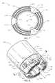
- FIG. 1illustrates a perspective view of a drilling tool including axially-tapered waterways according to an implementation of the present invention
- FIG. 2illustrates a bottom view of the drilling tool of FIG. 1 ;
- FIG. 3illustrates a partial cross-sectional view of the drilling tool of FIG. 2 taken along the section line 3 - 3 of FIG. 2 ;
- FIG. 4illustrates a perspective view of a drilling tool including axially-tapered and radially-tapered waterways according to an implementation of the present invention
- FIG. 5illustrates a bottom view of the drilling tool of FIG. 4 ;
- FIG. 6illustrates a partial cross-sectional view of the drilling tool of FIG. 5 taken along the section line 6 - 6 of FIG. 5 ;
- FIG. 7illustrates a bottom view of a drilling tool including axially-tapered and double radially-tapered waterways according to another implementation of the present invention
- FIG. 8illustrates a perspective view of a drilling tool including axially-tapered notches and axially-tapered enclosed slots according to an implementation of the present invention
- FIG. 9illustrates a cross-sectional view of the drilling tool of FIG. 8 taken along the section line 9 - 9 of FIG. 8 ;
- FIG. 10illustrates a partial cross-sectional view of the drilling tool of FIG. 9 taken along the section line 10 - 10 of FIG. 9 ;
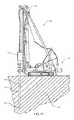
- FIG. 11illustrates a schematic view a drilling system including a drilling tool having axially-tapered waterways in accordance with an implementation of the present invention
- FIG. 12illustrates a perspective view of plug for use in forming drilling tools having axially-tapered waterways in accordance with an implementation of the present invention
- FIG. 13illustrates a side view of the plug of FIG. 11 ;
- FIG. 14illustrates a top view of the plug of FIG. 11 .
- Implementations of the present inventionare directed towards drilling tools, systems, and methods that can provide improved flow of drilling fluid about the cutting face of a drilling tool.
- one or more implementations of the present inventioninclude drilling tools having waterways that can increase the velocity of drilling fluid at the waterway entrance, and thereby, provide improved flushing of cuttings.
- one or more implementations of the present inventioninclude drilling tools having axially-tapered waterways.
- axially-tapered waterwayscan ensure that the opening of the waterway in the inner surface of the drilling tool can is smaller than the opening of the waterway in the outer surface of the drilling tool.
- the waterwaycan act like a nozzle by increasing the velocity of the drilling fluid at the waterway entrance in the inner surface of the drilling tool.
- the capability of axially-tapered waterways to increase the velocity of the drilling fluid at the waterway entrancecan provide increased flushing of cuttings, and can help prevent clogging of the waterways.
- axially-tapered waterwayscan provide improved flow of drilling fluid without significantly sacrificing bit body volume at the inside diameter or reducing the cutting surface of the bit face.
- the axially-tapered waterways of one or more implementations of the present inventioncan provide for increased drilling performance and increased drilling life.
- the drilling toolscan include axially and radially-tapered waterways, or in other words, double-tapered waterways.
- double-tapered waterwayscan help ensure that the waterway increases in dimensions in each axis as it extends from the inner surface of the drilling tool to the outer surface of the drilling tool.
- the increasing size of a double-tapered waterwaycan reduce the likelihood of debris lodging within the waterway, and thus, increase the drilling performance of the drilling tool.
- double-tapered waterwayscan also allow for a smaller waterway opening at the inside diameter, while still allowing for a large waterway opening at the outside diameter.
- one or more implementations of the present inventioncan increase the amount of matrix material at the inside diameter, and thus, help increase the life of the drill bit while also providing effective flushing.
- the increased life of such drill bitscan reduce drilling costs by reducing the need to trip a drill string from the bore hole to replace a prematurely worn drill bit.
- the drilling tools described hereincan be used to cut stone, subterranean mineral formations, ceramics, asphalt, concrete, and other hard materials.
- These drilling toolscan include, for example, core-sampling drill bits, drag-type drill bits, roller-cone drill bits, reamers, stabilizers, casing or rod shoes, and the like.
- core-sampling drill bitsdrag-type drill bits, roller-cone drill bits, reamers, stabilizers, casing or rod shoes, and the like.
- Figures and corresponding text included hereafterillustrate examples of impregnated, core-sampling drill bits, and methods of forming and using such drill bits.
- the systems, methods, and apparatus of the present inventioncan be used with other drilling tools, such as those mentioned hereinabove.
- FIGS. 1 and 2illustrate a perspective view and a top view, respectively, of a drilling tool 100 . More particularly, FIGS. 1 and 2 illustrate an impregnated, core-sampling drill bit 100 with axially-tapered waterways according to an implementation of the present invention.
- the drill bit 100can include a shank or blank 102 , which can be configured to connect the drill bit 100 to a component of a drill string.
- the drill bit 100can also include a cutting portion or crown 104 .
- FIGS. 1 and 2also illustrate that the drill bit 100 can define an interior space about its central axis 106 for receiving a core sample.
- both the shank 102 and crown 104can have a generally annular shape defined by an inner surface 107 and outer surface 108 .
- pieces of the material being drilledcan pass through the interior space of the drill bit 100 and up through an attached drill string.
- the drill bit 100may be any size, and therefore, may be used to collect core samples of any size. While the drill bit 100 may have any diameter and may be used to remove and collect core samples with any desired diameter, the diameter of the drill bit 100 can range in some implementations from about 1 inch to about 12 inches.
- the kerf of the drill bit 100i.e., the radius of the outer surface minus the radius of the inner surface
- the kerfcan range from about 1 ⁇ 4 inches to about 6 inches.
- the crown 104can be configured to cut or drill the desired materials during the drilling process.
- the crown 104 of the drill bit 100can include a cutting face 109 .
- the cutting face 109can be configured to drill or cut material as the drill bit 100 is rotated and advanced into a formation.
- the cutting face 109can include a plurality of grooves 110 extending generally axially into the cutting face 109 .
- the grooves 110can help allow for a quick start-up of a new drill bit 100 .
- the cutting face 109may not include grooves 110 or may include other features for aiding in the drilling process.
- the cutting face 109can also include waterways that may allow drilling fluid or other lubricants to flow across the cutting face 109 to help provide cooling during drilling.
- FIG. 1illustrates that the crown 104 can include a plurality of notches 112 that extend from the cutting face 109 in a generally axial direction into the crown 104 of the drill bit 100 . Additionally, the notches 112 can extend from the inner surface 107 of the crown 104 to the outer surface 108 of the crown 104 . As waterways, the notches 112 can allow drilling fluid to flow from the inner surface 107 of the crown 104 to the outer surface 108 of the crown 104 . Thus, the notches 112 can allow drilling fluid to flush cuttings and debris from the inner surface 107 to the outer surface 108 of the drill bit 100 , and also provide cooling to the cutting face 109 .
- the crown 104may have any number of notches that provides the desired amount of fluid/debris flow and also allows the crown 104 to maintain the structural integrity needed.
- FIGS. 1 and 2illustrate that the drill bit 100 includes nine notches 112 .
- the drill bit 100can include as few as one notch or as many 20 or more notches, depending on the desired configuration and the formation to be drilled.
- the notches 112may be evenly or unevenly spaced around the circumference of the crown 104 .
- FIG. 2depicts nine notches 112 evenly spaced from each other about the circumference of the crown 104 . In alternative implementations, however, the notches 112 can be staggered or otherwise not evenly spaced.
- each notch 112can be defined by at least three surfaces 112 a , 112 b , 112 c .
- each notch 112can be defined by a first side surface 112 a , an opposing side surface 112 b , and a top surface 112 c .
- each of the sides surfaces 112 a , 112 bcan extend from the inner surface 107 of the crown 104 to the outer surface 108 of the crown 104 in a direction generally normal to the inner surface of the crown 104 as illustrated by FIG. 2 .
- the width 114 of each notch 112 at the outer surface 108 of the crown 104can be approximately equal to the width 116 of each notch 112 at the inner surface 107 of the crown 104 .
- the circumferential distance 114 between the first side surface 112 a and the second side surface 112 b of each notch 112 at the outer surface 108can be approximately equal to the circumferential distance 116 between the first side surface 112 a and the second side surface 112 b of each notch 112 at the inner surface 107 .
- one or more of the side surfaces 112 a , 112 bmay include a radial and/or a circumferential taper.
- the notches 112can have any shape that allows them to operate as intended.
- the shape and configuration of the notches 112can be altered depending upon the characteristics desired for the drill bit 100 or the characteristics of the formation to be drilled.
- the FIG. 2illustrates that the notches can have a rectangular shape when viewed from cutting face 109 .
- the notchescan have square, triangular, circular, trapezoidal, polygonal, elliptical shape or any combination thereof.
- the notches 112may have any width or length that allows them to operate as intended.
- FIG. 2illustrates that the notches 112 can have a length (i.e., distance from the inside surface 107 to the outside surface 108 ) that is greater than their width (i.e., distance between opposing side surfaces 112 a and 112 b ).
- the notches 112can have a width greater than their length, or a width that is approximately equal to their length.
- the individual notches 112 in the crown 104can be configured uniformly with the same size and shape, or alternatively with different sizes and shapes.
- FIGS. 1-3illustrate all of the notches 112 in the crown 104 have the same size and configuration.
- the various notches 112 of the crown 104can include different sizes and configurations.
- the drill bit 100can include two different sizes of notches 112 that alternate around the circumference of the crown 104 .
- the waterwaysi.e., notches 112
- the top surface 112 c of each notch 112can taper from the inner surface 107 to the outer surface 108 in a direction generally from the cutting face 109 toward the shank 102 .
- the height or longitudinal dimension of each notch 112can increase as the notch 112 extends from the inner surface 107 to the outer surface 108 of the crown 104 .
- the longitudinal dimension 124 of each notch 112 at the outer surface 108can be greater than the longitudinal dimension 120 of each notch 112 at the inner surface 107 .
- each notch 112can extend into the cutting face 109 a first distance 120 at the inner surface 107 and extend into the cutting face 109 a second distance 124 at the outer surface 120 , where the second distance 124 is greater than the first distance 120 .
- the axial-taper of the notches 112can help ensure that the opening of each notch 112 at the inner surface 107 is smaller than the opening of each notch 112 at the outer surface 108 of the crown 104 . This difference in opening sizes can increase the velocity of drilling fluid at the inside surface 107 as it passes to the outside surface 108 of the crown 104 .
- the axial-taper of the notches 112can provide for more efficient flushing of cuttings and cooling of the cutting face 109 .
- the increasing size of the notches 112can also help ensure that debris does not jam or clog in the notch 112 as drilling fluid forces it from the inner surface 107 to the outer surface 108 .
- the axial-taper of the notches 112can provide the notches 112 with increasing size without reducing the size of the cutting face 109 .
- an increased surface area of the cutting face 109can provide for more efficient drilling.
- the axial-taper of the notches 112can provide for increased flushing and cooling, while also not decreasing the volume of crown material at the inside surface 107 .
- the increased volume of crown material at the inside surface 107can help increase the drilling life of the drill bit 100 .
- the crown 104can include additional features that can further aid in directing drilling fluid or other lubricants to the cutting face 109 or from the inside surface 107 to the outside surface 108 of the crown 104 .
- FIGS. 1-3illustrate that the drill bit 110 can include a plurality of flutes 122 , 124 extending radially into the crown 104 .
- the drill bit 100can include a plurality of inner flutes 122 that extend radially from the inner surface 107 toward the outer surface 108 .
- the plurality of inner flutes 122can help direct drilling fluid along the inner surface 107 of the drill bit 100 from the shank 102 toward the cutting face 109 . As shown in FIG.
- the inner flutes 122can extend from the shank 102 axially along the inner surface 107 of the crown 104 to the notches 112 .
- the inner flutes 122can help direct drilling fluid to the notches 112 .
- the inner flutes 122can extend from the shank 102 to the cutting face 109 , or even along the shank 102 .
- FIGS. 1-3additionally illustrate that in some implementations, the drill bit 100 can include a plurality of outer flutes 124 .
- the outer flutes 124can extend radially from the outer surface 108 toward the inner surface 107 of the crown 104 .
- the plurality of outer flutes 124can help direct drilling fluid along the outer surface 108 of the drill bit 100 from the notches 112 toward the shank 102 .
- the outer flutes 124can extend from the notches 112 axially along the outer surface 108 to the shank 102 .
- the outer flutes 124can extend from the cutting face 109 to the shank 102 , or even along the shank 102 .
- FIGS. 4-6illustrate various view of a drilling tool 200 including double-tapered waterways.
- FIG. 4illustrates a perspective view
- FIG. 5illustrates a bottom view
- FIG. 6illustrates a partial cross-sectional view of a core-sampling drill bit 200 having double-taped notches.
- the drill bit 200can include a shank 202 and a crown 204 .
- the crown 204can have a generally annular shape defined by an inner surface 207 and an outer surface 208 .
- the crown 204can additionally extend from the shank 202 and terminate in a cutting face 209 .
- the cutting face 209may extend from the inner surface 207 to the outer surface 208 in a direction generally normal to the longitudinal axis 206 of the drill bit 200 .
- the cutting face 209can include a plurality of grooves 210 .
- the crown 204can further include a plurality of double-tapered waterways 212 as explained in greater detail below.
- each of the notches 212can include a radial taper in addition to an axial taper. More specifically, each notch 212 can be defined by at least three surfaces 212 a , 212 b , 212 c . In particular, each notch 212 can be defined by a first side surface 212 a , an opposing side surface 212 b , and a top surface 212 c . In some implementations of the present invention, the first sides surface 212 a can extend from the inner surface 207 of the crown 204 to the outer surface 208 of the crown 204 in a direction generally normal to the inner surface of the crown 204 as illustrated by FIG. 5 .
- each notch 212can be radially tapered.
- the second side surface 212 b of each notch 212can taper from the inner surface 207 to the outer surface 208 in a direction generally clockwise around the circumference of the cutting face 209 .
- the terms “clockwise” and “counterclockwise”refer to directions relative to the longitudinal axis of a drill bit when viewing the cutting face of the drill bit.
- the width of each notch 212can increase as the notch 212 extends from the inner surface 207 to the outer surface 208 of the crown 204 .
- the width 214 of each notch 212 at the outer surface 208can be greater than the width 216 of each notch 212 at the inner surface 207 .
- the circumferential distance 214 between the first side surface 212 a and the second side surface 212 b of each notch 212 at the outer surface 208can be greater than the circumferential distance 216 between the first side surface 212 a and the second side surface 212 b of each notch 212 at the inner surface 207 .
- the radial taper of the notches 212can ensure that the opening of each notch 212 at the inner surface 207 is smaller than the opening of each notch 212 at the outer surface 208 of the crown 204 . This difference in opening sizes can increase the velocity of drilling fluid at the inside surface 207 as it passes to the outside surface 208 of the crown 204 .
- the radial taper of the notches 212can provide for more efficient flushing of cuttings and cooling of the cutting face 209 .
- the increasing width of the notches 212can also help ensure that debris does not jam or clog in the notch 212 as drilling fluid forces it from the inner surface 207 to the outer surface 208 .
- FIGS. 4-6illustrate that the radial taper of the notches 212 can be formed by a tapered second side surface 212 b .
- the first side surface 212 acan include a taper.
- the first side surface 212 acan taper from the inner surface 207 to the outer surface 208 in a direction generally counter-clockwise around the circumference of the cutting face 209 .
- the first side surface 212 a and the second side surface 212 bcan both include a taper extending from the inner surface 207 to the outer surface 208 in a direction generally clockwise around the circumference of the cutting face 209 .
- the radial taper of the second side surface 212 bcan have a larger taper than the first side surface 212 a in a manner that the width of the notch 212 increases as the notch 212 extends from the inner surface 207 to the outer surface 208 .
- the waterwaysi.e., notches 212
- the top surface 212 c of each notch 212can taper from the inner surface 207 to the outer surface 208 in a direction generally from the cutting face 209 toward the shank 202 .
- the longitudinal dimension of each notch 212can increase as the notch 212 extends from the inner surface 207 to the outer surface 208 of the crown 204 .
- the longitudinal dimension 224 of each notch 212 at the outer surface 208can be greater than the longitudinal dimension 220 of each notch 212 at the inner surface 207 .
- each notch 212can extend into the cutting face 209 a first distance 220 at the inner surface 207 and extend into the cutting face 209 a second distance 224 at the outer surface 208 , where the second distance 224 is greater than the first distance 220 .
- the axial taper of the notches 212can help ensure that the opening of each notch 212 at the inner surface 207 is smaller than the opening of each notch 212 at the outer surface 208 of the crown 204 . This difference in opening sizes can increase the velocity of drilling fluid at the inside surface 207 as it passes to the outside surface 208 of the crown 204 .
- the axial-taper of the notches 212can provide for more efficient flushing of cuttings and cooling of the cutting face 209 .
- the increasing size of the notches 212can also help ensure that debris does not jam or clog in the notch 212 as drilling fluid forces it from the inner surface 207 to the outer surface 208 .
- the double-tapered notches 212can ensure that the notches 212 increase in dimension in each axis (i.e., both radially and axially) as they extend from the inner surface 207 of the drill bit 200 to the outer surface 208 .
- the increasing size of the double-tapered notches 212can reduce the likelihood of debris lodging within the notches 212 , and thus, increase the drilling performance of the drill bit 200 .
- the increasing size of the double-tapered notches 212can help maximize the volume of matrix material at the inner surface 107 , and thereby can increase the life of the drill bit 200 by reducing premature drill bit wear at the inner surface 207 .
- the crown 204can include a plurality of flutes for directing drilling fluid, similar to the flutes described herein above in relation to the drill bit 100 .
- the drill bit 200can include a plurality of inner flutes 222 that can extend radially from the inner surface 207 toward the outer surface 208 .
- the plurality of inner flutes 222can help direct drilling fluid along the inner surface 207 of the drill bit 200 from the shank 202 toward the cutting face 209 .
- the inner flutes 222can extend from the shank 202 axially along the inner surface 207 to the notches 212 .
- the inner flutes 222can help direct drilling fluid to the notches 212 .
- the crown 204can include full inner flutes 222 a .
- the full inner flutes 222 acan extend from the shank 202 to the cutting face 209 without intersecting a notch 212 .
- the drill bit 200can include outer flutes 224 and full outer flutes 224 a .
- the outer flutes 224can extend from the shank 202 to a notch 212
- the full outer flutes 224 acan extend from the shank 202 to the cutting face 209 without intersecting a notch 212 .
- the full inner flutes 222 a and/or the full outer flutes 224 acan extend from the shank 202 to the cutting face 209 and also run along the a side surface 212 a , 212 b of a notch 212 .
- the waterways of the drilling toolscan include a radial taper.
- FIGS. 4-6illustrate notches 212 having a second side surface 212 b including a radial taper.
- both side surfacescan include a radial taper.
- FIG. 7illustrates a bottom view of a core-sampling drill bit 300 including double-tapered notches 312 where both of the side surfaces 312 a , 312 b include a radial taper.
- the drill bit 300can include a shank 302 and a crown 304 .
- the crown 304can have a generally annular shape defined by an inner surface 307 and an outer surface 308 .
- the crown 304can thus define a space about a central axis 306 for receiving a core sample.
- the crown 304can additionally extend from the shank 302 and terminate in a cutting face 309 .
- the cutting face 309can include a plurality of grooves 310 extending therein.
- the drill bit 300can include inner flutes 322 and outer flutes 324 for directing drilling fluid about the drill bit 300 .
- each notch 312can taper from the inner surface 307 to the outer surface 308 of the crown 304 in a direction generally clockwise around the circumference of the cutting face 309 .
- the first side surface 312 a of each notch 312can taper from the inner surface 307 to the outer surface 308 of the crown 304 in a direction generally counter-clockwise around the circumference of the cutting face 309 .
- the width of each notch 312can increase as the notch 312 extends from the inner surface 307 to the outer surface 308 of the crown 304 .
- the width 314 of each notch 312 at the outer surface 308can be greater than the width 316 of each notch 312 at the inner surface 307 .
- the circumferential distance 314 between the first side surface 312 a and the second side surface 312 b of each notch 312 at the outer surface 308can be greater than the circumferential distance 316 between the first side surface 312 a and the second side surface 312 b of each notch 312 at the inner surface 307 .
- each of the axially-tapered waterways described herein abovehave been notches extending into a cutting face of a crown.
- the present inventioncan include various other or additional waterways having an axial taper.
- the drilling tools of one or more implementations of the present inventioncan include one or more enclosed fluid slots having an axial taper, such as the enclosed fluid slots described in U.S. patent application Ser. No. 11/610,680, filed Dec. 14, 2006, entitled “Core Drill Bit with Extended Crown Longitudinal dimension,” the content of which is hereby incorporated herein by reference in its entirety.
- FIGS. 8-10illustrate various views of a core-sampling drill bit 400 that includes both axially-taper notches and axially-tapered enclosed slots.
- the drill bit 400can include a shank 402 and a crown 404 .
- the crown 404can have a generally annular shape defined by an inner surface 407 and an outer surface 408 .
- the crown 404can additionally extend from the shank 402 and terminate in a cutting face 409 .
- the cutting face 409can include a plurality of grooves 410 extending therein as shown in FIGS. 8-10 .
- the drill bit 400can include double-tapered notches 412 similar in configuration to double-taped notches 212 described above in relation to FIGS. 4-6 .
- notches 412can a top surface 412 c that can taper from the inner surface 407 to the outer surface 408 in a direction generally from the cutting face 409 toward the shank 402 .
- a first side surface 412 a of each notch 412can extend from the inner surface 407 of the crown 404 to the outer surface 408 of the crown 404 in a direction generally normal to the inner surface of the crown 404 .
- a second side surface 412 b of each notch 412can taper from the inner surface 407 to the outer surface 408 in a direction generally clockwise around the circumference of the cutting face 409 .
- the drill bitcan include a plurality of enclosed slots 430 .
- the enclosed slots 430can include an axial and/or a radial taper as explained in greater detail below.
- the crown 404erodes through drilling, the notches 412 can wear away. As the erosion progresses, the enclosed slots 430 can become exposed at the cutting face 409 and then thus become notches.
- the configuration of drill bit 400can thus allow the longitudinal dimension of the crown 404 to be extended and lengthened without substantially reducing the structural integrity of the drill bit 400 .
- the extended longitudinal dimension of the crown 404can in turn allow the drill bit 400 to last longer and require less tripping in and out of the borehole to replace the drill bit 400 .
- FIG. 8illustrates that the crown 404 can include a plurality of enclosed slots 430 that extend a distance from the cutting face 409 toward the shank 402 of the drill bit 400 .
- the enclosed slots 430can extend from the inner surface 407 of the crown 404 to the outer surface 408 of the crown 404 .
- the enclosed slots 430can allow drilling fluid to flow from the inner surface 407 of the crown 404 to the outer surface 408 of the crown 404 .
- the enclosed slots 430can allow drilling fluid to flush cuttings and debris from the inner surface 407 to the outer surface 408 of the drill bit 400 , and also provide cooling to the cutting face 409 .
- the crown 404may have any number of enclosed slots 430 that provides the desired amount of fluid/debris flow or crown longitudinal dimension, while also allowing the crown 404 to maintain the structural integrity needed.
- FIGS. 8 and 10illustrate that the drill bit 400 can include six enclosed slots 430 .
- the drill bit 400can include as few as one enclosed slot or as many 20 or more enclosed slots, depending on the desired configuration and the formation to be drilled.
- the enclosed slots 430may be evenly or unevenly spaced around the circumference of the crown 404 .
- FIGS. 8-10depict enclosed slots 430 evenly spaced from each other about the circumference of the crown 404 . In alternative implementations, however, the enclosed slots 430 can be staggered or otherwise not evenly spaced.
- each enclosed slot 430can be defined by four surfaces 430 a , 430 b , 430 c , 430 d .
- each enclosed slot 430can be defined by a first side surface 430 a , an opposing side surface 430 b , a top surface 430 c , and an opposing bottom surface 430 d .
- each of the sides surfaces 430 a , 430 bcan extend from the inner surface 407 of the crown 404 to the outer surface 408 of the crown 404 in a direction generally normal to the inner surface of the crown 404 .
- one or more of the side surfaces 430 a , 430 bmay include a radial and/or a circumferential taper.
- the enclosed slots 430can have any shape that allows them to operate as intended, and the shape can be altered depending upon the characteristics desired for the drill bit 400 or the characteristics of the formation to be drilled.
- the FIG. 9illustrates that the enclosed slots can have a trapezoidal shape.
- the enclosed slots 430can have square, triangular, circular, rectangular, polygonal, or elliptical shapes, or any combination thereof.
- the enclosed slots 430may have any width or length that allows them to operate as intended.
- FIG. 9illustrates that the enclosed slots 430 have a length (i.e., distance from the inside surface 407 to the outside surface 408 ) that is greater than their width (i.e., distance between opposing side surfaces 430 a and 430 b ).
- the individual enclosed slots 430 in the crown 404can be configured uniformly with the same size and shape, or alternatively with different sizes and shapes.
- FIGS. 8-10illustrate all of the enclosed slots 430 in the crown 404 can have the same size and configuration.
- the various enclosed slots 430 of the crown 404can include different sizes and configurations.
- the crown 404can include various rows of waterways.
- FIG. 8illustrates that the crown 404 can include a row of notches 412 that extend a first distance 432 from the cutting face 409 into the crown 404 .
- FIG. 8illustrates that the crown 404 can include a first row of enclosed slots 430 commencing in the crown 404 a second distance 434 from the cutting face 409 , and a second row of enclosed slots 430 commencing in the crown 404 a third distance 436 from the cutting face 409 .
- the crown 404can include a single row of enclosed slots 430 or multiple rows of enclosed slots 430 each axially staggered from the other.
- a portion of the notches 412can axially overlap the first row of enclosed slots 430 .
- the first distance 432can be greater than the second distance 434 .
- a portion of the enclosed slots 430 in the first rowcan axially overlap the enclosed slots in the second row.
- the axially overlap of the waterways 412 , 430can help ensure that before notches 412 have completely eroded away during drilling, the first row of enclosed slots 430 will open to become notches 412 , allowing the drill bit 400 to continue to cut efficiently as the drill bit 400 erodes.
- the enclosed slots 430 in the first rowcan be circumferentially offset from the notches 412 .
- the enclosed slots 430 in the second rowcan be circumferentially offset from the enclosed slots 430 in the first row and the notches 412 .
- one or more of the enclosed slots 430 in the first and second rowcan be circumferentially aligned with each other or the notches 412 .
- the enclosed slots 430can include a double-taper.
- FIG. 9illustrates that each of the enclosed slots 430 can include a radial taper.
- the first side surface 430 acan extend from the inner surface 407 of the crown 404 to the outer surface 408 of the crown 404 in a direction generally normal to the inner surface 407 of the crown 404 as illustrated by FIG. 9 .
- each enclosed slot 430can taper from the inner surface 407 to the outer surface 408 in a direction generally clockwise around the circumference of the crown 404 .
- the width of each enclosed slot 430can increase as the enclosed slot 430 extends from the inner surface 407 to the outer surface 408 of the crown 404 .
- the width 414 of each enclosed slot 430 at the outer surface 408can be greater than the width 416 of each enclosed slot 430 at the inner surface 407 .
- the circumferential distance 414 between the first side surface 430 a and the second side surface 430 b of each enclosed slot 430 at the outer surface 408can be greater than the circumferential distance 416 between the first side surface 430 a and the second side surface 430 b of each enclosed slot 430 at the inner surface 407 .
- the radial taper of the enclosed slots 430can ensure that the opening of each enclosed slot 430 at the inner surface 407 is smaller than the opening of each enclosed slot 430 at the outer surface 408 of the crown 404 . This difference in opening sizes can increase the velocity of drilling fluid at the inside surface 407 as it passes to the outside surface 408 of the crown 404 .
- the radial-taper of the enclosed slots 430can provide for more efficient flushing of cuttings and cooling of the drill bit 400 .
- the increasing width of the enclosed slots 430can also help ensure that debris does not jam or clog in the enclosed slot 430 as drilling fluid forces it from the inner surface 407 to the outer surface 408 .
- FIGS. 8-10also illustrate that the radial taper of the enclosed slots 430 can be formed by a tapered second side surface 430 b .
- the first side surface 430 acan include a taper.
- the first side surface 430 acan taper from the inner surface 407 to the outer surface 408 in a direction generally counter-clockwise around the circumference of the crown 404 .
- the waterwaysi.e., enclosed slots 430
- the top surface 430 c of each enclosed slot 430can taper from the inner surface 407 to the outer surface 408 in a direction generally from the cutting face 409 toward the shank 402 .
- the longitudinal dimension of each enclosed slot 430can increase as the enclosed slot 430 extends from the inner surface 407 to the outer surface 408 of the crown 404 .
- the longitudinal dimension 444 of each enclosed slot 430 at the outer surface 408can be greater than the longitudinal dimension 442 of each enclosed slot 430 at the inner surface 407 .
- the top surface 430 c of each enclosed slot 430 at the outer surface 408can be farther from the cutting face 409 than the top surface 430 c of each enclosed slot 430 at the inner surface 407 .
- each enclosed slot 430can taper from the inner surface 407 to the outer surface 408 in a direction generally from the shank 402 toward the cutting face 409 .
- the longitudinal dimension of each enclosed slot 430can increase as the enclosed slot 430 extends from the inner surface 407 to the outer surface 408 of the crown 404 .
- the bottom surface 430 d of each enclosed slot 430 at the outer surface 408can be closer to the cutting face 409 than the bottom surface 430 d of each enclosed slot 430 at the inner surface 407 .
- the enclosed slots 430can include a double-axial taper where both the top surface 430 c and the bottom surface 430 d include a taper.
- the axial-taper of the enclosed slots 430can ensure that the opening of each enclosed slot 430 at the inner surface 407 is smaller than the opening of each enclosed slot 430 at the outer surface 408 of the crown 404 . This difference in opening sizes can increase the velocity of drilling fluid at the inside surface 407 as it passes to the outside surface 408 of the crown.
- the axial-taper of the enclosed slots 430can provide for more efficient flushing of cuttings and cooling of the drill bit 404 .
- the increasing size of the enclosed slots 430can also help ensure that debris does not jam or clog in the enclosed slots 430 as drilling fluid forces it from the inner surface 407 to the outer surface 408 .
- the double-.sub.tapered enclosed slots 430can ensure that the enclosed slots 430 increase in dimension in each axis as they extend from the inner surface 407 of the drill bit 400 to the outer surface 408 .
- the increasing size of the double-tapered enclosed slots 430can reduce the likelihood of debris lodging within the enclosed slots 430 , and thus, increase the drilling performance of the drill bit 400 .
- the double-tapered enclosed slots 430can provide efficient flushing while also reducing the removal of material at the inner surface 407 of the drill bit 400 .
- the double-tapered enclosed slots 430can help increase the drilling life of the drill bit by helping to reduce premature wear of the drill bit 400 near the inner surface 407 .
- FIGS. 8-10further illustrate that the corners of the waterways 412 , 430 can include a rounded surface or chamfer.
- the rounded surface of the corners of the waterways 412 , 430can help reduce the concentration of stresses, and thus can help increase the strength of the drill bit 400 .
- the crown 404can include a plurality of flutes for directing drilling fluid, similar to the flutes described herein above in relation to the drill bit 200 .
- the drill bit 400can include a plurality of inner flutes 422 that extend radially from the inner surface 407 toward the outer surface 408 .
- the plurality of inner flutes 422can help direct drilling fluid along the inner surface 407 of the drill bit 400 from the shank 402 toward the cutting face 409 .
- the inner flutes 422can extend from the shank 402 axially along the inner surface 407 to the notches 412 .
- the inner flutes 422can help direct drilling fluid to the notches 412 .
- the crown 404can include full inner flutes 422 b that intersect an enclosed slot 430 .
- the full inner flutes 422 bcan extend from the shank 402 to the cutting face 409 .
- the full inner flutes 422 bcan intersect one or more enclosed slots 430 as illustrated by FIG. 10 .
- the drill bit 400can include outer flutes 424 and full outer flutes 424 a .
- the outer flutes 424can extend from the shank 402 to a notch 412
- the full outer flutes 424 acan extend from the shank 402 to the cutting face 409 while also intersecting an enclosed slot 430 .
- the drill bit 400can further includes enclosed fluid channels 440 .
- the enclosed fluid channels 440can be enclosed within the drill bit 400 between the inner surface 407 and the outer surface 408 .
- the enclosed fluid channels 440can extend from the shank 402 to a waterway 412 , 430 , or to the cutting face 409 .
- the enclosed fluid channels 440can thus direct drilling fluid to the cutting face 409 without having to flow across the inner surface 407 of the crown 404 .
- the enclosed fluid channels 440can help ensure that a core sample is not flushed out of the drill bit 400 by the drilling fluid.
- the drill bit 400can include additional or alternative features to the enclosed fluid channels 440 that can help prevent washing away of a core sample.
- the drill bit 400can include a thin wall along the inner surface 407 of the crown 404 .
- the thin wallcan close off the waterways 412 , 430 so they do not extend radially to the interior of the crown 404 .
- the thin wallcan help reduce any fluid flowing to the interior of the crown 404 , and thus, help prevent a sandy or fragmented core sample from washing away.
- the drill bit 400may not include inner flutes 422 .
- drilling fluidcan flow into the enclosed fluid channels 440 , axially within the crown 404 to a waterway 412 , 430 , and then out of the waterway 412 , 430 to the cutting face 409 or outer surface 408 .
- the shanks 102 , 202 , 302 , 402 of the various drilling tools of the present inventioncan be configured to secure the drill bit to a drill string component.
- the shank 102 , 202 , 302 , 402can include an American Petroleum Institute (API) threaded connection portion or other features to aid in attachment to a drill string component.
- APIAmerican Petroleum Institute
- the shank portion 102 , 202 , 302 , 402may be formed from steel, another iron-based alloy, or any other material that exhibits acceptable physical properties.
- the crown 104 , 204 , 304 , 404 of the drill tools of the present inventioncan be made of one or more layers.
- the crown 104 , 204 , 304 , 404can include two layers.
- the crown 104 , 204 , 304 , 404can include a matrix layer, which performs the drilling operation, and a backing layer, which connects the matrix layer to the shank 102 , 202 , 302 , 402 .
- the matrix layercan contain the abrasive cutting media that abrades and erodes the material being drilled.
- the crown 104 , 204 , 304 , 404can be formed from a matrix of hard particulate material, such as for example, a metal.
- the hard particular materialmay include a powered material, such as for example, a powered metal or alloy, as well as ceramic compounds.
- the hard particulate materialcan include tungsten carbide.
- tungsten carbidemeans any material composition that contains chemical compounds of tungsten and carbon, such as, for example, WC, W2C, and combinations of WC and W2C.
- tungsten carbideincludes, for example, cast tungsten carbide, sintered tungsten carbide, and macrocrystalline tungsten.
- the hard particulate materialcan include carbide, tungsten, iron, cobalt, and/or molybdenum and carbides, borides, alloys thereof, or any other suitable material.
- the crown 104 , 204 , 304 , 404can also include a plurality of abrasive cutting media dispersed throughout the hard particulate material.
- the abrasive cutting mediacan include one or more of natural diamonds, synthetic diamonds, polycrystalline diamond or thermally stable diamond products, aluminum oxide, silicon carbide, silicon nitride, tungsten carbide, cubic boron nitride, alumina, seeded or unseeded sol-gel alumina, or other suitable materials.
- the abrasive cutting media used in the drilling tools of one or more implementations of the present inventioncan have any desired characteristic or combination of characteristics.
- the abrasive cutting mediacan be of any size, shape, grain, quality, grit, concentration, etc.
- the abrasive cutting mediacan be very small and substantially round in order to leave a smooth finish on the material being cut by the core-sampling drill bit 100 , 200 , 300 , 400 .
- the cutting mediacan be larger to cut aggressively into the material or formation being drill.
- the abrasive cutting mediacan be dispersed homogeneously or heterogeneously throughout the crown 104 , 204 , 304 , 404 .
- the abrasive cutting mediacan be aligned in a particular manner so that the drilling properties of the media are presented in an advantageous position with respect to the crown 104 , 204 , 304 , 404 .
- the abrasive cutting mediacan be contained in the crown 104 , 204 , 304 , 404 in a variety of densities as desired for a particular use. For example, large abrasive cutting media spaced further apart can cut material more quickly than small abrasive cutting media packed tightly together.
- the size, density, and shape of the abrasive cutting mediacan be provided in a variety of combinations depending on desired cost and performance of the drill bit 100 , 200 , 300 , 400 .
- the crown 104 , 204 , 304 , 404may be manufactured to any desired specification or given any desired characteristic(s). In this way, the crown 104 , 204 , 304 , 404 may be custom-engineered to possess optimal characteristics for drilling specific materials. For example, a hard, abrasion resistant matrix may be made to drill soft, abrasive, unconsolidated formations, while a soft ductile matrix may be made to drill an extremely hard, non-abrasive, consolidated formation. In this way, the matrix hardness may be matched to particular formations, allowing the matrix layer to erode at a controlled, desired rate.
- FIG. 11illustrate or describe one such drilling system with which drilling tools of the present invention can be used.
- FIG. 11illustrates or describes one such drilling system with which drilling tools of the present invention can be used.
- the drilling system shown and described in FIG. 11is only one example of a system with which drilling tools of the present invention can be used.
- FIG. 11illustrates a drilling system 500 that includes a drill head 510 .
- the drill head 510can be coupled to a mast 520 that in turn is coupled to a drill rig 530 .
- the drill head 510can be configured to have one or more tubular members 540 coupled thereto.
- Tubular memberscan include, without limitation, drill rods, casings, and down-the-hole hammers.
- the tubular members 540will be described herein after as drill string components.
- the drill string component 540can in turn be coupled to additional drill string components 540 to form a drill or tool string 550 .
- the drill string 550can be coupled to drilling tool 560 including axially-tapered waterways, such as the core-sampling drill bits 100 , 200 , 300 , 400 described hereinabove.
- the drilling tool 560can be configured to interface with the material 570 , or formation, to be drilled.
- the drill head 510 illustrated in FIG. 11can be configured rotate the drill string 550 during a drilling process.
- the drill head 510can vary the speed at which the drill head 510 rotates.
- the rotational rate of the drill head and/or the torque the drill head 510 transmits to the drill string 550can be selected as desired according to the drilling process.
- the drilling system 500can be configured to apply a generally longitudinal downward force to the drill string 550 to urge the drilling tool 560 into the formation 570 during a drilling operation.
- the drilling system 500can include a chain-drive assembly that is configured to move a sled assembly relative to the mast 520 to apply the generally longitudinal force to the drilling tool bit 560 as described above.
- the term “longitudinal”means along the length of the drill string 550 . Additionally, as used herein the terms “upper,” “top,” and “above” and “lower” and “below” refer to longitudinal positions on the drill string 550 . The terms “upper,” “top,” and “above” refer to positions nearer the drill head 510 and “lower” and “below” refer to positions nearer the drilling tool 560 .
- a diamond-impregnated core sampling drill bit 100 , 200 , 300 , 400can be attached to the end of the drill string 550 , which is in turn connected to a drilling machine or rig 530 .
- the drill bit 560can grind away the materials in the subterranean formations 570 that are being drilled.
- the core samples that are drilled awaycan be withdrawn from the drill string 550 .
- the cutting portion of the drill bit 560can erode over time because of the grinding action. This process can continue until the cutting portion of a drill bit 560 has been consumed and the drilling string 550 can then be tripped out of the borehole and the drill bit 560 replaced.
- Implementations of the present inventionalso include methods of forming drilling tools having axially-tapered waterways.
- the followingdescribes at least one method of forming drilling tools having axially-tapered waterways.
- one of ordinary skill in the artwill recognize that the methods explained in detail can be modified to install a wide variety of configurations using one or more components of the present invention.
- the term “infiltration” or “infiltrating” as used hereininvolves melting a binder material and causing the molten binder to penetrate into and fill the spaces or pores of a matrix. Upon cooling, the binder can solidify, binding the particles of the matrix together.
- the term “sintering” as used hereinmeans the removal of at least a portion of the pores between the particles (which can be accompanied by shrinkage) combined with coalescence and bonding between adjacent particles.
- FIGS. 12-14illustrate various views of a plug 600 that can be used to form an axially-tapered waterway, such as the notches 212 of drill bit 200 or slots 430 of drill bit 400 .
- the plug 600can include surfaces corresponding to the surfaces of an axially-tapered waterway.
- the plug 600can include a top surface 602 , a bottom surface 604 , a first side surface 608 , and a second side surface 606 .
- the plug 600can include chamfers 610 connecting the surfaces 602 , 604 , 606 , 608 of the plug 600 .
- the top surface 602 of the plug 600can include a taper such that a first end of the plug 600 can have a first longitudinal dimension 612 and a second end of the plug 600 can have a second longitudinal dimension 614 that is greater than the first longitudinal dimension 612 .
- the taper of the top surface 602can help form the axial taper of a waterway.
- FIG. 14illustrates that the second side surface 606 can include a taper such that the first end of the plug 600 can have a first width 616 and the second end of the plug 600 can have a second width 618 that is greater than the first width 616 .
- the taper of the second side surface 606can help form the radial taper of a waterway.
- the shape and configuration of the plug 600can vary depending upon the desired shape and configuration of a waterway to be formed with the plug 600 .
- the plug 600can be formed from graphite, carbon, or other material with suitable material characteristics.
- the plug 600can be formed from a material which will not significantly melt or decay during infiltration or sintering. As explained in greater detail below, by using a plug 600 formed from a material that does not significantly melt, the plug 600 can be relatively easily removed from an infiltrated drilling tool.
- One method of the present inventioncan include providing a matrix of hard particulate material and abrasive cutting media, such as the previously described hard particulate materials and abrasive cutting media materials.
- the hard particulate materialcan comprise a power mixture.
- the methodcan also involve pressing or otherwise shaping the matrix into a desired form.
- the methodcan involve forming the matrix into the shape of an annular crown.
- the methodcan then involve placing a plurality of plugs into the matrix.
- the methodcan involve placing the bottom surface 602 into a surface of the annular crown that corresponds to a cutting face in order to form a notch 112 , 212 , 312 , 412 .
- the methodcan involve placing a plug 600 into the body of the annular crown a distance from the surface of the annular crown that corresponds to a cutting face to form an enclosed slot 430 .
- the methodcan then infiltrating the matrix with a binder.
- the bindercan comprise copper, zinc, silver, molybdenum, nickel, cobalt, or mixture and alloys thereof.
- the bindercan cool thereby bonding to the matrix (hard particulate material and abrasive cutting media), thereby binding the matrix together.
- the bindermay not significantly bond to the plug 600 , thereby allowing removal of the plug 600 to expose an axially or double tapered waterway.
- Another, method of the present inventiongenerally includes providing a matrix and filling a mold having plugs 600 placed therein with the matrix.
- the moldcan be formed from a material to which a binder material may not significantly bond to, such as for example, graphite or carbon.
- the methodcan then involve densification of the matrix by gravity and/or vibration.
- the methodcan then involve infiltrating matrix with a binder comprising one or more of the materials previously mentioned.
- the bindercan cool thereby bonding to the matrix (hard particulate material and abrasive cutting media), thereby binding the matrix together.
- the bindermay not significantly bond to the plug 600 or the mold, thereby allowing removal of the plug 600 to expose an axially or double tapered waterway.
- one or more methods of the present inventioncan include sintering the matrix to a desired density.
- sinteringinvolves densification and removal of porosity within a structure
- the structure being sinteredcan shrink during the sintering process.
- a structurecan experience linear shrinkage of between 1% and 40% during sintering.
- the time and/or temperature of the infiltration processcan be increased to allow the binder to fill-up a great number and greater amount of the pores of the matrix. This can both reduce the shrinkage during sintering, and increase the strength of the resulting drilling tool.
- the present inventioncan thus be embodied in other specific forms without departing from its spirit or essential characteristics.
- the described embodimentsare to be considered in all respects only as illustrative and not restrictive.
- the axially-tapered waterwayscan be formed by removing material from the crown instead of using plugs.
- the axially-tapered waterwayscan be formed by machining or cutting the waterways into the crown using water jets, lasers, Electrical Discharge Machining (EDM), or other techniques.
- EDMElectrical Discharge Machining
Landscapes
- Engineering & Computer Science (AREA)
- Geology (AREA)
- Life Sciences & Earth Sciences (AREA)
- Mining & Mineral Resources (AREA)
- Physics & Mathematics (AREA)
- Environmental & Geological Engineering (AREA)
- Fluid Mechanics (AREA)
- Mechanical Engineering (AREA)
- General Life Sciences & Earth Sciences (AREA)
- Geochemistry & Mineralogy (AREA)
- Processing Of Stones Or Stones Resemblance Materials (AREA)
- Earth Drilling (AREA)
- Drilling Tools (AREA)
Abstract
Description
Claims (34)
Priority Applications (3)
| Application Number | Priority Date | Filing Date | Title |
|---|---|---|---|
| US13/914,233US9074429B2 (en) | 2006-12-14 | 2013-06-10 | Drill bits with axially-tapered waterways |
| US14/246,888US9500036B2 (en) | 2006-12-14 | 2014-04-07 | Single-waterway drill bits and systems for using same |
| US14/753,853US9903165B2 (en) | 2009-09-22 | 2015-06-29 | Drill bits with axially-tapered waterways |
Applications Claiming Priority (8)
| Application Number | Priority Date | Filing Date | Title |
|---|---|---|---|
| US11/610,680US7628228B2 (en) | 2006-12-14 | 2006-12-14 | Core drill bit with extended crown height |
| US12/564,779US7918288B2 (en) | 2006-12-14 | 2009-09-22 | Drill bits with enclosed fluid slots and method |
| US12/564,540US7828090B2 (en) | 2006-12-14 | 2009-09-22 | Drill bits with enclosed fluid slots and internal flutes |
| US12/567,477US7958954B2 (en) | 2006-12-14 | 2009-09-25 | Drill bits with enclosed slots |
| US12/568,231US7874384B2 (en) | 2006-12-14 | 2009-09-28 | Drill bits with increased crown height |
| US12/568,204US7909119B2 (en) | 2006-12-14 | 2009-09-28 | Drill bits with notches and enclosed slots |
| US12/638,229US8459381B2 (en) | 2006-12-14 | 2009-12-15 | Drill bits with axially-tapered waterways |
| US13/914,233US9074429B2 (en) | 2006-12-14 | 2013-06-10 | Drill bits with axially-tapered waterways |
Related Parent Applications (1)
| Application Number | Title | Priority Date | Filing Date |
|---|---|---|---|
| US12/638,229ContinuationUS8459381B2 (en) | 2006-12-14 | 2009-12-15 | Drill bits with axially-tapered waterways |
Related Child Applications (2)
| Application Number | Title | Priority Date | Filing Date |
|---|---|---|---|
| US14/246,888Continuation-In-PartUS9500036B2 (en) | 2006-12-14 | 2014-04-07 | Single-waterway drill bits and systems for using same |
| US14/753,853ContinuationUS9903165B2 (en) | 2009-09-22 | 2015-06-29 | Drill bits with axially-tapered waterways |
Publications (2)
| Publication Number | Publication Date |
|---|---|
| US20130313026A1 US20130313026A1 (en) | 2013-11-28 |
| US9074429B2true US9074429B2 (en) | 2015-07-07 |
Family
ID=44226751
Family Applications (3)
| Application Number | Title | Priority Date | Filing Date |
|---|---|---|---|
| US12/638,229Expired - Fee RelatedUS8459381B2 (en) | 2006-12-14 | 2009-12-15 | Drill bits with axially-tapered waterways |
| US13/914,233Expired - Fee RelatedUS9074429B2 (en) | 2006-12-14 | 2013-06-10 | Drill bits with axially-tapered waterways |
| US14/753,853Active2027-11-11US9903165B2 (en) | 2009-09-22 | 2015-06-29 | Drill bits with axially-tapered waterways |
Family Applications Before (1)
| Application Number | Title | Priority Date | Filing Date |
|---|---|---|---|
| US12/638,229Expired - Fee RelatedUS8459381B2 (en) | 2006-12-14 | 2009-12-15 | Drill bits with axially-tapered waterways |
Family Applications After (1)
| Application Number | Title | Priority Date | Filing Date |
|---|---|---|---|
| US14/753,853Active2027-11-11US9903165B2 (en) | 2009-09-22 | 2015-06-29 | Drill bits with axially-tapered waterways |
Country Status (12)
| Country | Link |
|---|---|
| US (3) | US8459381B2 (en) |
| EP (1) | EP2513405B1 (en) |
| CN (2) | CN106884617B (en) |
| AU (1) | AU2010337217B2 (en) |
| BR (1) | BRPI1011892A2 (en) |
| CA (1) | CA2784465C (en) |
| CL (1) | CL2011003228A1 (en) |
| ES (1) | ES2710550T3 (en) |
| PE (2) | PE20121057A1 (en) |
| TR (1) | TR201902237T4 (en) |
| WO (1) | WO2011081775A1 (en) |
| ZA (2) | ZA201205225B (en) |
Cited By (6)
| Publication number | Priority date | Publication date | Assignee | Title |
|---|---|---|---|---|
| US9279292B2 (en) | 2013-11-20 | 2016-03-08 | Longyear Tm, Inc. | Drill bits having flushing and systems for using same |
| US9500036B2 (en) | 2006-12-14 | 2016-11-22 | Longyear Tm, Inc. | Single-waterway drill bits and systems for using same |
| US9506298B2 (en) | 2013-11-20 | 2016-11-29 | Longyear Tm, Inc. | Drill bits having blind-hole flushing and systems for using same |
| US9903165B2 (en) | 2009-09-22 | 2018-02-27 | Longyear Tm, Inc. | Drill bits with axially-tapered waterways |
| USD873373S1 (en)* | 2018-07-23 | 2020-01-21 | Oso Perforating, Llc | Perforating gun contact device |
| USD877286S1 (en)* | 2018-07-23 | 2020-03-03 | Oso Perforating, Llc | Perforating gun contact ring |
Families Citing this family (28)
| Publication number | Priority date | Publication date | Assignee | Title |
|---|---|---|---|---|
| US9267332B2 (en) | 2006-11-30 | 2016-02-23 | Longyear Tm, Inc. | Impregnated drilling tools including elongated structures |
| MX2010002236A (en)* | 2007-09-05 | 2010-03-25 | Groupe Fordia Inc | Drill bit. |
| US9884374B2 (en)* | 2015-09-03 | 2018-02-06 | Irwin Industrial Tool Company | Hole cutter with multiple fulcrums |
| US9808869B2 (en) | 2010-01-13 | 2017-11-07 | Irwin Industrial Tool Company | Hole cutter with chip egress aperture |
| US10137507B2 (en) | 2010-01-13 | 2018-11-27 | Irwin Industrial Tool Company | Hole cutter with multiple fulcrums |
| US8991524B2 (en) | 2010-09-13 | 2015-03-31 | Longyear Tm, Inc. | Impregnated drill bits with integrated reamers |
| US20130098691A1 (en) | 2011-10-25 | 2013-04-25 | Longyear Tm, Inc. | High-strength, high-hardness binders and drilling tools formed using the same |
| DE102013204421B4 (en)* | 2013-03-14 | 2019-07-11 | Robert Bosch Gmbh | Cylindrical drill body for a hole saw |
| CN103437713B (en)* | 2013-08-07 | 2015-11-04 | 中国地质大学(武汉) | A self-sharpening ring tooth impregnated diamond drill bit |
| CA154829S (en) | 2013-08-09 | 2014-10-06 | Hilti Ag | Cutting head for a drilling core bit |
| EP3309302A1 (en) | 2013-09-05 | 2018-04-18 | Geopier Foundation Company, Inc. | Apparatuses for constructing displacement aggregate piers |
| CN103670285B (en)* | 2013-12-16 | 2016-06-01 | 江西坚德实业有限公司 | A kind of high-efficiency broad spectrum geology drill bit and manufacture method |
| BR112016015209A2 (en)* | 2013-12-30 | 2017-08-08 | Longyear Tm Inc | DRILL AND DRILLING SYSTEM |
| PE20161426A1 (en)* | 2014-04-07 | 2017-01-06 | Longyear Tm Inc | SINGLE WATER TRAIL DRILL BITS AND SYSTEMS TO USE THEM |
| US9598911B2 (en)* | 2014-05-09 | 2017-03-21 | Baker Hughes Incorporated | Coring tools and related methods |
| EP3037201A1 (en)* | 2014-12-22 | 2016-06-29 | HILTI Aktiengesellschaft | Method for producing a closed drill ring for a core drill bit |
| PE20171508A1 (en)* | 2015-03-05 | 2017-10-20 | Longyear Tm Inc | DISCHARGE DRILL HOLES |
| US10125553B2 (en) | 2015-03-06 | 2018-11-13 | Baker Hughes Incorporated | Coring tools for managing hydraulic properties of drilling fluid and related methods |
| CN105545214B (en)* | 2016-02-03 | 2017-11-03 | 中国有色桂林矿产地质研究院有限公司 | Major-minor bottom spray type laser welding diamond bit and its manufacture method |
| CN106050149B (en)* | 2016-07-27 | 2019-01-04 | 安徽省地质矿产勘查局313地质队 | Spiral tooth step bottom spraying type diamond drill bit |
| USD845362S1 (en) | 2017-12-04 | 2019-04-09 | Black & Decker Inc. | Holesaw |
| US10648146B1 (en)* | 2017-12-22 | 2020-05-12 | Martin Reulet | Precast concrete screw cylinder system and method for soil stabilization and erosion control |
| NO20181642A1 (en)* | 2018-01-12 | 2019-07-15 | Comrod As | Slotted drill with interchangeable tooth ring |
| CN110145241B (en)* | 2018-02-10 | 2024-11-12 | 西南石油大学 | A low torque diamond drill bit suitable for drilling in hard formations |
| CA3135423A1 (en) | 2019-03-29 | 2020-10-08 | Bly Ip Inc. | Underground drill rig and systems and methods of using same |
| KR102230524B1 (en)* | 2019-11-11 | 2021-03-22 | 동신다이아몬드공업 주식회사 | Core drill with diamond segment |
| PE20231259A1 (en)* | 2020-12-29 | 2023-08-22 | Longyear Tm Inc | DRILLING BIT WITH REINFORCED FACE |
| CN113622827B (en)* | 2021-08-31 | 2022-05-17 | 中国地质大学(武汉) | A diamond drill bit for drilling into fractured hard rock layers |
Citations (55)
| Publication number | Priority date | Publication date | Assignee | Title |
|---|---|---|---|---|
| US367956A (en) | 1887-08-09 | Hoeatio j | ||
| US774384A (en) | 1903-12-22 | 1904-11-08 | Philip E Fisher | Water-conducting pipe or the like. |
| US1572386A (en) | 1923-07-16 | 1926-02-09 | Leroy G Gates | Rotary drill bit |
| US2046400A (en)* | 1934-07-20 | 1936-07-07 | Chicago Pneumatic Tool Co | Rotary face bit |
| US2147849A (en) | 1937-08-23 | 1939-02-21 | Leo William Dominic | Tobacco container |
| US2147843A (en) | 1938-03-18 | 1939-02-21 | R S Patrick Duluth | Method of casting diamond core drill bits |
| US2495400A (en) | 1946-06-03 | 1950-01-24 | Jr Edward B Williams | Core bit |
| US2644672A (en) | 1951-01-29 | 1953-07-07 | Ted C Mathews | Diamond bit protector |
| US2966949A (en) | 1958-07-16 | 1961-01-03 | Jersey Prod Res Co | Full hole permanent drill bit |
| US2969122A (en) | 1955-03-31 | 1961-01-24 | Norman Ind Inc Van | Hollow drill |
| US3095935A (en) | 1958-09-25 | 1963-07-02 | Jersey Prod Res Co | Coring bit |
| US3215215A (en) | 1962-08-27 | 1965-11-02 | Exxon Production Research Co | Diamond bit |
| USRE26669E (en) | 1968-05-09 | 1969-09-30 | Drilling bit | |
| US3495359A (en) | 1968-10-10 | 1970-02-17 | Norton Co | Core drill |
| US3692127A (en) | 1971-05-10 | 1972-09-19 | Walter R Hampe | Rotary diamond core bit |
| US3860354A (en) | 1971-12-29 | 1975-01-14 | Everett D Hougen | Annular hole cutter |
| US4128136A (en) | 1977-12-09 | 1978-12-05 | Lamage Limited | Drill bit |
| US4186628A (en)* | 1976-11-30 | 1980-02-05 | General Electric Company | Rotary drill bit and method for making same |
| US4189015A (en) | 1978-08-21 | 1980-02-19 | Acker Drill Company, Inc. | Drill bits for obtaining core samples |
| US4190126A (en) | 1976-12-28 | 1980-02-26 | Tokiwa Industrial Co., Ltd. | Rotary abrasive drilling bit |
| US4208154A (en) | 1978-03-21 | 1980-06-17 | Gundy William P | Core drill |
| US4452554A (en) | 1981-09-21 | 1984-06-05 | Hougen Everett D | Annular hole cutter |
| US4499959A (en) | 1983-03-14 | 1985-02-19 | Christensen, Inc. | Tooth configuration for an earth boring bit |
| US4538944A (en) | 1981-09-21 | 1985-09-03 | Hougen Everett D | Annular cutter |
| US4822757A (en) | 1987-11-10 | 1989-04-18 | Mitsubishi Denki Kabushiki Kaisha | Semiconductor device and method of manufacturing the same |
| SU1571209A1 (en) | 1988-07-20 | 1990-06-15 | Государственный Научно-Исследовательский И Проектный Институт Нефтяной Промышленности | Double core dredger |
| US5025871A (en) | 1989-04-05 | 1991-06-25 | Aulette Stewart | Drilling method and rotary drill bit crown |
| US5069584A (en) | 1989-01-20 | 1991-12-03 | Hilti Aktiengesellschaft | Hollow drilling tool |
| USD342270S (en) | 1992-09-29 | 1993-12-14 | Ehwa Diamond Ind. Co., Ltd. | Core drill for perforating stone |
| US5316416A (en) | 1992-09-29 | 1994-05-31 | Ehwa Diamond Ind. Co., Ltd. | Diamond cutting tool for hard articles |
| US5628376A (en) | 1994-10-15 | 1997-05-13 | Hilti Aktiengesellschaft | Drilling tool bit with a carrier member and cutter members |
| US5823276A (en) | 1996-12-24 | 1998-10-20 | Beck, Iii; August H. | Diamond-tipped core barrel and method of using same |
| US5836409A (en) | 1994-09-07 | 1998-11-17 | Vail, Iii; William Banning | Monolithic self sharpening rotary drill bit having tungsten carbide rods cast in steel alloys |
| US5932508A (en) | 1996-09-04 | 1999-08-03 | Armstrong; Caoimhin Padraig | Manufacture of a metal bonded abrasive product |
| CN2386178Y (en) | 1999-03-23 | 2000-07-05 | 江汉石油钻头股份有限公司 | Mixed drilling bit |
| US6123490A (en) | 1998-05-22 | 2000-09-26 | Halliburton Energy Services, Inc. | Apparatus for machining round holes |
| WO2001092677A1 (en) | 2000-05-31 | 2001-12-06 | Boart Longyear Pty Ltd | Improved core sampling drill bit |
| US6595844B1 (en) | 1998-09-10 | 2003-07-22 | Atock Co., Ltd. | Outer-diameter blade, inner-diameter blade, core drill and processing machines using same ones |
| US6675919B2 (en)* | 2000-02-04 | 2004-01-13 | Frank's Casing Crew And Rental Tools, Inc. | Tubular piling apparatus and method |
| WO2004108333A1 (en) | 2003-06-05 | 2004-12-16 | Kabushiki Kaisha Miyanaga | Core cutter |
| US6945339B2 (en) | 2002-01-18 | 2005-09-20 | Max Co., Ltd. | Core drill |
| WO2006004494A1 (en) | 2004-07-01 | 2006-01-12 | Atlas Copco Craelius Ab | A drill bit |
| US7055626B2 (en)* | 2002-03-15 | 2006-06-06 | Baker Hughes Incorporated | Core bit having features for controlling flow split |
| WO2006076795A1 (en) | 2005-01-18 | 2006-07-27 | Groupe Fordia Inc | Bit for drilling a hole |
| US7189036B1 (en) | 2005-04-29 | 2007-03-13 | Forest City Tool, Inc. | Coring bit |
| US7341118B2 (en) | 2005-06-20 | 2008-03-11 | Northern Centre For Advanced Technology Inc. | Rotating dry drilling bit |
| WO2008076908A2 (en) | 2006-12-14 | 2008-06-26 | Boart Longyear | Core drill bit with extended matrix height |
| USD622745S1 (en) | 2006-12-14 | 2010-08-31 | Longyear Tm, Inc. | Drill bit with tapered waterway |
| US7793716B2 (en) | 2006-04-21 | 2010-09-14 | Bj Services Company, U.S.A. | Apparatus and methods for limiting debris flow back into an underground base pipe of an injection well |
| US7874284B2 (en) | 2007-12-05 | 2011-01-25 | Denso Corporation | Fuel supply system having fuel filter installed downstream of feed pump |
| CA2785465A1 (en) | 2009-12-24 | 2011-06-30 | Clariant Finance (Bvi) Limited | Multifunctional additives having an improved flow capability |
| WO2011081775A1 (en) | 2009-12-15 | 2011-07-07 | Longyear Tm, Inc. | Drill bits with axially-tapered waterways |
| US7984773B2 (en) | 2008-05-13 | 2011-07-26 | Longyear Tm, Inc. | Sonic drill bit for core sampling |
| AU2011201711B1 (en) | 2006-12-14 | 2011-07-28 | Boart Longyear Manufacturing And Distribution Inc. | Core drill bit with extended matrix height |
| US20140216826A1 (en) | 2006-12-14 | 2014-08-07 | Longyear Tm, Inc. | Single-waterway drill bits and systems for using same |
Family Cites Families (45)
| Publication number | Priority date | Publication date | Assignee | Title |
|---|---|---|---|---|
| US367946A (en) | 1887-08-09 | Advertising device | ||
| US2493178A (en) | 1946-06-03 | 1950-01-03 | Jr Edward B Williams | Drill bit |
| US2931630A (en) | 1957-12-30 | 1960-04-05 | Hycalog Inc | Drill bit |
| US3175629A (en) | 1962-11-01 | 1965-03-30 | Jersey Prod Res Co | Jet bit |
| US3384192A (en) | 1965-12-27 | 1968-05-21 | Gulf Research Development Co | Hydraulic jet bit |
| US3831753A (en) | 1972-12-18 | 1974-08-27 | Gulf Research Development Co | Slotted in-line screen |
| US3981371A (en)* | 1975-06-06 | 1976-09-21 | Jamie Malcolm Wallis | Core sampling drill |
| US4494618A (en) | 1982-09-30 | 1985-01-22 | Strata Bit Corporation | Drill bit with self cleaning nozzle |
| US4538691A (en) | 1984-01-30 | 1985-09-03 | Strata Bit Corporation | Rotary drill bit |
| US4640374A (en)* | 1984-01-30 | 1987-02-03 | Strata Bit Corporation | Rotary drill bit |
| US4739844A (en)* | 1984-04-02 | 1988-04-26 | Becker Drills, Inc. | Hammer drill bit and sub-assembly |
| US4776411A (en) | 1987-03-23 | 1988-10-11 | Smith International, Inc. | Fluid flow control for drag bits |
| US4869330A (en) | 1988-01-20 | 1989-09-26 | Eastman Christensen Company | Apparatus for establishing hydraulic flow regime in drill bits |
| US5025875A (en) | 1990-05-07 | 1991-06-25 | Ingersoll-Rand Company | Rock bit for a down-the-hole drill |
| SE503323C2 (en) | 1990-12-21 | 1996-05-28 | Sandvik Ab | Drill bit, preferably lower drill bit |
| US6454030B1 (en) | 1999-01-25 | 2002-09-24 | Baker Hughes Incorporated | Drill bits and other articles of manufacture including a layer-manufactured shell integrally secured to a cast structure and methods of fabricating same |
| EP1165929A1 (en) | 1999-03-03 | 2002-01-02 | Earth Tool Company L.L.C. | Method and apparatus for directional boring |
| CN2410409Y (en) | 2000-01-22 | 2000-12-13 | 卢元宝 | PDC drill bit capable of complete drilling bending passway |
| AUPQ639900A0 (en)* | 2000-03-21 | 2000-04-15 | Dht Technologies Limited | Segment for a core drill bit and method of manufacture |
| US20020011356A1 (en) | 2000-03-29 | 2002-01-31 | Hill John L. | Drilling equipment and method |
| US6800610B2 (en) | 2000-06-19 | 2004-10-05 | The Uab Research Foundation | Osteoclast secreted chemokine and uses thereof |
| US6474425B1 (en) | 2000-07-19 | 2002-11-05 | Smith International, Inc. | Asymmetric diamond impregnated drill bit |
| US7182156B2 (en) | 2003-06-12 | 2007-02-27 | Luc Charland | System for overburden drilling |
| JP2005145041A (en) | 2003-10-23 | 2005-06-09 | Ishihara Kikai Kogyo Kk | Non-core type bit, non-core drill device and cooling water supplying/discharging method therefor |
| SE526344C2 (en) | 2003-12-09 | 2005-08-30 | Sandvik Intellectual Property | Rock drill bit |
| GB2415208B (en) | 2004-06-18 | 2008-12-24 | Statoil Asa | Drag bit |
| CA2509854C (en) | 2005-06-13 | 2009-11-17 | Northern Centre For Advanced Technology Inc. | A rotating dry drilling bit |
| WO2008073307A2 (en) | 2006-12-11 | 2008-06-19 | Baker Hughes Incorporated | Impregnated bit with changeable hydraulic nozzles |
| US9279292B2 (en) | 2013-11-20 | 2016-03-08 | Longyear Tm, Inc. | Drill bits having flushing and systems for using same |
| US9506298B2 (en) | 2013-11-20 | 2016-11-29 | Longyear Tm, Inc. | Drill bits having blind-hole flushing and systems for using same |
| MX2010002236A (en) | 2007-09-05 | 2010-03-25 | Groupe Fordia Inc | Drill bit. |
| CN201258693Y (en) | 2008-06-17 | 2009-06-17 | 王海 | Diamond compact deflecting bit |
| US8590646B2 (en) | 2009-09-22 | 2013-11-26 | Longyear Tm, Inc. | Impregnated cutting elements with large abrasive cutting media and methods of making and using the same |
| US8839886B2 (en) | 2009-11-09 | 2014-09-23 | Atlas Copco Secoroc Llc | Drill bit with recessed center |
| CN102078224B (en) | 2009-11-26 | 2012-11-28 | 东莞宝钰精瓷工业有限公司 | Design method of implant prosthesis |
| US8215449B2 (en) | 2009-12-02 | 2012-07-10 | Longyear Tm, Inc. | Muffler system for noise abatement and ice control |
| AU2015203268B2 (en) | 2009-12-15 | 2017-01-12 | Boart Longyear Manufacturing And Distribution Inc. | Core-sampling drill bit |
| US8991524B2 (en) | 2010-09-13 | 2015-03-31 | Longyear Tm, Inc. | Impregnated drill bits with integrated reamers |
| US20130186693A1 (en) | 2010-09-21 | 2013-07-25 | Flexidrill Limited | Hybrid drill bit |
| US20120125687A1 (en) | 2010-11-24 | 2012-05-24 | Tiger 19 Partners, Ltd. | Hard Rock Rotary Drill Bit and Method of Drilling Using Crowned Cutter Elements |
| USD656167S1 (en) | 2011-08-08 | 2012-03-20 | Dunnahoe Duane C | Mill |
| BR112015000409A2 (en) | 2012-07-09 | 2017-06-27 | Adc Czech Republic Sro | cable management system including a dividing / filtering tray |
| CN102852462B (en) | 2012-08-24 | 2015-04-29 | 北京探矿工程研究所 | Composite inserted tooth blade type diamond comprehensive drill bit |
| BR112016015209A2 (en) | 2013-12-30 | 2017-08-08 | Longyear Tm Inc | DRILL AND DRILLING SYSTEM |
| PE20171508A1 (en) | 2015-03-05 | 2017-10-20 | Longyear Tm Inc | DISCHARGE DRILL HOLES |
- 2009
- 2009-12-15USUS12/638,229patent/US8459381B2/ennot_activeExpired - Fee Related
- 2010
- 2010-12-03WOPCT/US2010/058871patent/WO2011081775A1/enactiveApplication Filing
- 2010-12-03ESES10841452Tpatent/ES2710550T3/enactiveActive
- 2010-12-03TRTR2019/02237Tpatent/TR201902237T4/enunknown
- 2010-12-03BRBRPI1011892Apatent/BRPI1011892A2/ennot_activeIP Right Cessation
- 2010-12-03EPEP10841452.5Apatent/EP2513405B1/enactiveActive
- 2010-12-03PEPE2011002055Apatent/PE20121057A1/ennot_activeApplication Discontinuation
- 2010-12-03CNCN201710075295.2Apatent/CN106884617B/ennot_activeExpired - Fee Related
- 2010-12-03CNCN201080057021.7Apatent/CN102782243B/ennot_activeExpired - Fee Related
- 2010-12-03PEPE2015000664Apatent/PE20150992A1/enactiveIP Right Grant
- 2010-12-03CACA2784465Apatent/CA2784465C/enactiveActive
- 2010-12-03AUAU2010337217Apatent/AU2010337217B2/ennot_activeCeased
- 2011
- 2011-12-20CLCL2011003228Apatent/CL2011003228A1/enunknown
- 2012
- 2012-07-13ZAZA2012/05225Apatent/ZA201205225B/enunknown
- 2013
- 2013-06-10USUS13/914,233patent/US9074429B2/ennot_activeExpired - Fee Related
- 2013-10-22ZAZA2013/07869Apatent/ZA201307869B/enunknown
- 2015
- 2015-06-29USUS14/753,853patent/US9903165B2/enactiveActive
Patent Citations (84)
| Publication number | Priority date | Publication date | Assignee | Title |
|---|---|---|---|---|
| US367956A (en) | 1887-08-09 | Hoeatio j | ||
| US774384A (en) | 1903-12-22 | 1904-11-08 | Philip E Fisher | Water-conducting pipe or the like. |
| US1572386A (en) | 1923-07-16 | 1926-02-09 | Leroy G Gates | Rotary drill bit |
| US2046400A (en)* | 1934-07-20 | 1936-07-07 | Chicago Pneumatic Tool Co | Rotary face bit |
| US2147849A (en) | 1937-08-23 | 1939-02-21 | Leo William Dominic | Tobacco container |
| US2147843A (en) | 1938-03-18 | 1939-02-21 | R S Patrick Duluth | Method of casting diamond core drill bits |
| US2495400A (en) | 1946-06-03 | 1950-01-24 | Jr Edward B Williams | Core bit |
| US2644672A (en) | 1951-01-29 | 1953-07-07 | Ted C Mathews | Diamond bit protector |
| US2969122A (en) | 1955-03-31 | 1961-01-24 | Norman Ind Inc Van | Hollow drill |
| US2966949A (en) | 1958-07-16 | 1961-01-03 | Jersey Prod Res Co | Full hole permanent drill bit |
| US3095935A (en) | 1958-09-25 | 1963-07-02 | Jersey Prod Res Co | Coring bit |
| US3215215A (en) | 1962-08-27 | 1965-11-02 | Exxon Production Research Co | Diamond bit |
| USRE26669E (en) | 1968-05-09 | 1969-09-30 | Drilling bit | |
| US3495359A (en) | 1968-10-10 | 1970-02-17 | Norton Co | Core drill |
| US3692127A (en) | 1971-05-10 | 1972-09-19 | Walter R Hampe | Rotary diamond core bit |
| US3860354A (en) | 1971-12-29 | 1975-01-14 | Everett D Hougen | Annular hole cutter |
| US4186628A (en)* | 1976-11-30 | 1980-02-05 | General Electric Company | Rotary drill bit and method for making same |
| US4190126A (en) | 1976-12-28 | 1980-02-26 | Tokiwa Industrial Co., Ltd. | Rotary abrasive drilling bit |
| US4128136A (en) | 1977-12-09 | 1978-12-05 | Lamage Limited | Drill bit |
| US4208154A (en) | 1978-03-21 | 1980-06-17 | Gundy William P | Core drill |
| US4189015A (en) | 1978-08-21 | 1980-02-19 | Acker Drill Company, Inc. | Drill bits for obtaining core samples |
| US4452554A (en) | 1981-09-21 | 1984-06-05 | Hougen Everett D | Annular hole cutter |
| US4538944A (en) | 1981-09-21 | 1985-09-03 | Hougen Everett D | Annular cutter |
| US4499959A (en) | 1983-03-14 | 1985-02-19 | Christensen, Inc. | Tooth configuration for an earth boring bit |
| US4822757A (en) | 1987-11-10 | 1989-04-18 | Mitsubishi Denki Kabushiki Kaisha | Semiconductor device and method of manufacturing the same |
| SU1571209A1 (en) | 1988-07-20 | 1990-06-15 | Государственный Научно-Исследовательский И Проектный Институт Нефтяной Промышленности | Double core dredger |
| US5069584A (en) | 1989-01-20 | 1991-12-03 | Hilti Aktiengesellschaft | Hollow drilling tool |
| US5025871A (en) | 1989-04-05 | 1991-06-25 | Aulette Stewart | Drilling method and rotary drill bit crown |
| USD342270S (en) | 1992-09-29 | 1993-12-14 | Ehwa Diamond Ind. Co., Ltd. | Core drill for perforating stone |
| US5316416A (en) | 1992-09-29 | 1994-05-31 | Ehwa Diamond Ind. Co., Ltd. | Diamond cutting tool for hard articles |
| US5836409A (en) | 1994-09-07 | 1998-11-17 | Vail, Iii; William Banning | Monolithic self sharpening rotary drill bit having tungsten carbide rods cast in steel alloys |
| US5628376A (en) | 1994-10-15 | 1997-05-13 | Hilti Aktiengesellschaft | Drilling tool bit with a carrier member and cutter members |
| US5932508A (en) | 1996-09-04 | 1999-08-03 | Armstrong; Caoimhin Padraig | Manufacture of a metal bonded abrasive product |
| US5823276A (en) | 1996-12-24 | 1998-10-20 | Beck, Iii; August H. | Diamond-tipped core barrel and method of using same |
| US6123490A (en) | 1998-05-22 | 2000-09-26 | Halliburton Energy Services, Inc. | Apparatus for machining round holes |
| US6595844B1 (en) | 1998-09-10 | 2003-07-22 | Atock Co., Ltd. | Outer-diameter blade, inner-diameter blade, core drill and processing machines using same ones |
| CN2386178Y (en) | 1999-03-23 | 2000-07-05 | 江汉石油钻头股份有限公司 | Mixed drilling bit |
| US6675919B2 (en)* | 2000-02-04 | 2004-01-13 | Frank's Casing Crew And Rental Tools, Inc. | Tubular piling apparatus and method |
| WO2001092677A1 (en) | 2000-05-31 | 2001-12-06 | Boart Longyear Pty Ltd | Improved core sampling drill bit |
| US6945339B2 (en) | 2002-01-18 | 2005-09-20 | Max Co., Ltd. | Core drill |
| US7055626B2 (en)* | 2002-03-15 | 2006-06-06 | Baker Hughes Incorporated | Core bit having features for controlling flow split |
| CN1798624A (en) | 2003-06-05 | 2006-07-05 | 株式会社宫永 | Core cutter |
| US7611312B2 (en)* | 2003-06-05 | 2009-11-03 | Kabushiki Kaisha Miyanaga | Core cutter |
| WO2004108333A1 (en) | 2003-06-05 | 2004-12-16 | Kabushiki Kaisha Miyanaga | Core cutter |
| WO2006004494A1 (en) | 2004-07-01 | 2006-01-12 | Atlas Copco Craelius Ab | A drill bit |
| WO2006076795A1 (en) | 2005-01-18 | 2006-07-27 | Groupe Fordia Inc | Bit for drilling a hole |
| US7641004B2 (en) | 2005-01-18 | 2010-01-05 | Groupe Fordia Inc. | Drill bit |
| US7189036B1 (en) | 2005-04-29 | 2007-03-13 | Forest City Tool, Inc. | Coring bit |
| US7341118B2 (en) | 2005-06-20 | 2008-03-11 | Northern Centre For Advanced Technology Inc. | Rotating dry drilling bit |
| US7793716B2 (en) | 2006-04-21 | 2010-09-14 | Bj Services Company, U.S.A. | Apparatus and methods for limiting debris flow back into an underground base pipe of an injection well |
| US7909119B2 (en) | 2006-12-14 | 2011-03-22 | Longyear Tm, Inc. | Drill bits with notches and enclosed slots |
| AU2011201713A1 (en) | 2006-12-14 | 2011-05-12 | Longyear Tm, Inc. | Core drill bit with extended matrix height |
| EP2122111A2 (en) | 2006-12-14 | 2009-11-25 | Boart Longyear | Core drill bit with extended matrix height |
| US7628228B2 (en) | 2006-12-14 | 2009-12-08 | Longyear Tm, Inc. | Core drill bit with extended crown height |
| CA2826590A1 (en) | 2006-12-14 | 2008-06-26 | Longyear Tm, Inc. | Core drill bit with extended matrix height |
| CN101652532A (en) | 2006-12-14 | 2010-02-17 | 宝长年公司 | Coring bit with matrix height of prolongation |
| ZA200903801B (en) | 2006-12-14 | 2010-08-25 | Boart Longyear | Core drill bit with extended matrix height |
| USD622745S1 (en) | 2006-12-14 | 2010-08-31 | Longyear Tm, Inc. | Drill bit with tapered waterway |
| AU2007333850A1 (en) | 2006-12-14 | 2008-06-26 | Boart Longyear Manufacturing And Distribution Inc. | Core drill bit with extended matrix height |
| US7828090B2 (en) | 2006-12-14 | 2010-11-09 | Longyear Tm, Inc. | Drill bits with enclosed fluid slots and internal flutes |
| US7874384B2 (en) | 2006-12-14 | 2011-01-25 | Longyear Tm, Inc. | Drill bits with increased crown height |
| US20140216826A1 (en) | 2006-12-14 | 2014-08-07 | Longyear Tm, Inc. | Single-waterway drill bits and systems for using same |
| WO2008076908A2 (en) | 2006-12-14 | 2008-06-26 | Boart Longyear | Core drill bit with extended matrix height |
| US7918288B2 (en) | 2006-12-14 | 2011-04-05 | Longyear Tm, Inc. | Drill bits with enclosed fluid slots and method |
| AU2011201709A1 (en) | 2006-12-14 | 2011-05-12 | Boart Longyear Manufacturing And Distribution Inc. | Core drill bit with extended matrix height |
| AU2011201710A1 (en) | 2006-12-14 | 2011-05-12 | Boart Longyear Manufacturing And Distribution Inc. | Core drill bit with extended matrix height |
| AU2011201707A1 (en) | 2006-12-14 | 2011-05-12 | Longyear Tm, Inc. | Core drill bit with extended matrix height |
| CA2671061A1 (en) | 2006-12-14 | 2008-06-26 | Kristian Shayne Drivdahl | Core drill bit with extended matrix height |
| AU2011201706A1 (en) | 2006-12-14 | 2011-05-12 | Longyear Tm, Inc. | Core drill bit with extended matrix height |
| US7958954B2 (en) | 2006-12-14 | 2011-06-14 | Longyear Tm, Inc. | Drill bits with enclosed slots |
| US8459381B2 (en)* | 2006-12-14 | 2013-06-11 | Longyear Tm, Inc. | Drill bits with axially-tapered waterways |
| US8051929B2 (en) | 2006-12-14 | 2011-11-08 | Longyear Tm, Inc. | Core drill bits with enclosed fluid slots |
| USD647114S1 (en) | 2006-12-14 | 2011-10-18 | Longyear Tm, Inc. | Drill bit with tapered waterway |
| USD647115S1 (en) | 2006-12-14 | 2011-10-18 | Longyear Tm, Inc. | Drill bit waterway |
| AU2011201711B1 (en) | 2006-12-14 | 2011-07-28 | Boart Longyear Manufacturing And Distribution Inc. | Core drill bit with extended matrix height |
| US7874284B2 (en) | 2007-12-05 | 2011-01-25 | Denso Corporation | Fuel supply system having fuel filter installed downstream of feed pump |
| US7984773B2 (en) | 2008-05-13 | 2011-07-26 | Longyear Tm, Inc. | Sonic drill bit for core sampling |
| CA2784465A1 (en) | 2009-12-15 | 2011-07-07 | Longyear Tm, Inc. | Drill bits with axially-tapered waterways |
| WO2011081775A1 (en) | 2009-12-15 | 2011-07-07 | Longyear Tm, Inc. | Drill bits with axially-tapered waterways |
| AU2010337217A1 (en) | 2009-12-15 | 2012-07-05 | Longyear Tm, Inc. | Drill bits with axially-tapered waterways |
| PE20121057A1 (en) | 2009-12-15 | 2012-08-09 | Longyear Tm Inc | DRILLING HOLES WITH WATER PATHWAYS OF AXIALLY DECREASING SECTION |
| EP2513405A1 (en) | 2009-12-15 | 2012-10-24 | Longyear TM, Inc. | Drill bits with axially-tapered waterways |
| CN102782243A (en) | 2009-12-15 | 2012-11-14 | 长年Tm公司 | Drill bits with axially tapered channels |
| CA2785465A1 (en) | 2009-12-24 | 2011-06-30 | Clariant Finance (Bvi) Limited | Multifunctional additives having an improved flow capability |
Non-Patent Citations (80)
| Title |
|---|
| Amendment after Non-Final Office Action dated Nov. 24, 2008 for U.S. Appl. No. 11/610,680, filed May 29, 2000, issued as US 7,628,228 (Inventor: Drivdahl// Applicant: Boart Longyear) (20 pages). |
| Amendment and Response to Final Office action dated Oct. 27, 2010 for U.S. Appl. No. 12/568,204, filed Sep. 28, 2009, issued as 7,909,119 (Inventor: Drivdahl// Applicant: Boart Longyear) (13 pages). |
| Amendment and Response to Non-Final Office Action dated Dec. 21, 2010 for U.S. Appl. No. 12/567,477, filed Sep. 25, 2009 and issued as US 7,958,954 (Inventor: Drivdahl//Applicant: Boart Longyear) (12 pages). |
| Amendment and Response to Non-Final Office Action dated Jul. 8, 2010 for U.S. Appl. No. 12/568,204, filed Sep. 28, 2009, issued as 7,909,119 (Inventor: Drivdahl//Applicant: Boart Longyear) (14 pages). |
| Amendment and Response to Non-Final Office Action dated Mar. 28, 2011 for U.S. Appl. No. 12/909,187, filed Oct. 21, 2010 and issued as US 8,051,929 (Inventor: Drivdahl//Applicant: Boart Longyear) (12 pages). |
| Amendment and Response to Non-Final Office Action dated Sep. 1, 2010 U.S. Appl. No. 12/567,477, filed Sep. 25, 2009 and issued as US 7,958,954 (Inventor: Drivdahl//Applicant: Boart Longyear) (5 pages). |
| Amendment and Response to Office Action dated Dec. 7, 2010 for U.S. Appl. No. 12/564,779, filed May 29, 2000, issued as US 7,918,288 (Inventor:Drivdahl// Applicant: Boart Longyear) (14 pages). |
| Amendment and Response to Office Action dated Jul. 26, 2010 from U.S. Appl. No. 12/564,540, filed Sep. 22, 2009, issued as U.S. 7,828,090 (Inventor: Drivdahl// Applicant: Boart Longyear) (12 pages). |
| Amendment and Response to Office Action dated Jun. 23, 2010 for U.S. Appl. No. 12/564,779, filed May 29, 2000, issued as US 7,918,288 (Inventor:Drivdahl// Applicant: Boart Longyear) (13 pages). |
| Amendment and Response to Office Action dated Sep. 3, 2010 for U.S. Appl. No. 12/568,231, filed Sep. 28, 2009 and issued as US 7,674,384 (Inventor: Drivdahl//Applicant: Boart Longyear) (11 pages). |
| Examiner Interview Summary dated Aug. 13, 2010 for U.S. Appl. No. 12/567,477, filed Sep. 25, 2009 and issued as US 7,958,954 (Inventor: Drivdahl//Applicant: Boart Longyear) (2 pages). |
| Examiner Interview Summary dated Aug. 13, 2010 for U.S. Appl. No. 12/568,231, filed Sep. 28, 2009 and issued as US 7,674,384 (Inventor: Drivdahl//Applicant: Boart Longyear) (2 pages). |
| Examiner Interview Summary dated Jan. 20, 2011 for for U.S. Appl. No. 12/909,187, filed Oct. 21, 2010 and issued as US 8,051,929 (Inventor: Drivdahl//Applicant: Boart Longyear) (3 pages). |
| Examiner Interview Summary dated Jun. 10, 2010 for U.S. Appl. No. 12/564,540, filed Sep. 22, 2009, issued as U.S. 7,828,090 (Inventor: Drivdahl// Applicant: Boart Longyear) (1 page). |
| Examiner interview Summary dated Jun. 10, 2010 for U.S. Appl. No. 12/564,779, filed May 29, 2000, issued as US 7,918,288 (Inventor: Drivdahl//Applicant: Boart Longyear) (3 pages). |
| Examiner Interview Summary dated Jun. 10, 2010 for U.S. Appl. No. 12/568,204, filed Sep. 28, 2009, issued as 7,909,119 (Inventor: Drivdahl//Applicant: Boart Longyear) (1 page). |
| Examiner Interview Summary dated Nov. 13, 2008 for U.S. Appl. No. 11/610,680, filed May 29, 2000, issued as US 7,628,228 (Inventor: Drivdahl// Applicant: Boart Longyear) (1 page). |
| Examiner Interview Summary dated Nov. 26, 2011 for U.S. Appl. No. 12/568,204, filed Sep. 28, 2009, issued as 7,909,119 (Inventor: Drivdahl// Applicant: Boart Longyear) (1 page). |
| Examiner Interview Summary dated Oct. 19, 2010 for U.S. Appl. No. 12/564,779, filed May 29, 2000, issued as US 7,918,288 (Inventor: Drivdahl//Applicant: Boart Longyear) (1 page). |
| Examiner Interview Summary dated Oct. 19, 2010 for U.S. Appl. No. 12/567,477 filed Sep. 25, 2009 and issued as US 7,958,954 (Inventor: Drivdahl//Applicant: Boart Longyear) (2 pages). |
| Examiner Interview Summary dated Oct. 19, 2010 for U.S. Appl. No. 12/568,204, filed Sep. 28, 2009, issued as 7,909,119 (Inventor: Drivdahl//Applicant: Boart Longyear) (2 pages). |
| Final Office Action dated Aug. 23, 2010 U.S. Appl. No. 12/568,204, filed Sep. 28, 2009, issued as 7,909,119 (Inventor: Drivdahl//Applicant: Boart Longyear) (9 pages). |
| Final Rejection issued Sep. 7, 2009 for U.S. Appl. No. 11/610,680, filed May 29, 2000, issued as US 7,628,228 (Inventor: Drivdahl// Applicant: Boart Longyear) (6 pages). |
| International Preliminary Report on Patentability issued Jun. 16, 2009 for International Patent Application PCT/US2007/087619 which was filed Dec. 14, 2007 and published as WO 2008/076908 (Applicant: Boart Longyear// Inventor: Drivdahl) (1 page). |
| International Preliminary Report on Patentability issued Jun. 19 2012 for International patent Application PCT/US2010/058871 and published as WO2011/081775 on Jul. 7, 2011 (Applicant: Longyear// Inventor: Cory Pearce) (4 pages.). |
| International Search Report issued Jun. 7, 2011 for International patent Application PCT/US2010/058871 and published as WO2011/081775 on Jul. 7, 2011 (Applicant: Longyear// Inventor: Cory Pearce) (3 pages). |
| International Search Report mailed Aug. 1, 2008 for International Patent Application PCT/US2007/087619 which was filed Dec. 14, 2007 and published as WO 2008/076908 (Applicant: Boart Longyear// Inventor: Drivdahl) (3 pages). |
| Issue Notification dated Apr. 5, 2011 for U.S. Appl. No. 12/564,779, filed May 29, 2000, issued as US 7,918,288 (Inventor: Drivdahl// Applicant: Boart Longyear) (1 page). |
| Issue Notification dated Aug. 11, 2010 from U.S. Appl. No. 29/354,579, filed Jan. 26, 2010 (1 page). |
| Issue Notification dated Dec. 8, 2009 for U.S. Appl. No. 11/610,680, filed May 29, 2000 and issued as US 7,628,228 (Inventor: Drivdahl// Applicant: Boart Longyear) (1 page). |
| Issue Notification dated Jan. 5, 2011 for U.S. Appl. No. 12/568,231, filed Sep. 28, 2009 and issued as US 7,674,384 (Inventor: Drivdahl// Applicant: Boart Longyear) (1 page). |
| Issue Notification dated Mar. 2, 2011 from U.S. Appl. No. 12/568,204, filed Sep. 28, 2009 and issued as 7,909,119 (Inventor: Drivdahl// Applicant: Boart Longyear) (1 page). |
| Issue Notification dated May 22, 2013 for U.S. Appl. No. 12/638,229, filed Dec. 15, 2009 and issued as US 8,459,381 (Applicant: Boart Longyear// Inventor: Cody Pearce ) (1 page). |
| Issue Notification dated May 25, 2011 for U.S. Appl. No. 12/567,477, filed Sep. 25, 2009 and issued as US 7,958,954 (Inventor: Drivdahl//Applicant: Boart Longyear) (1 page). |
| Issue Notification dated Novemeber 9, 2010 from U.S. Appl. No. 12/564,540, filed Sep. 22, 2009, issued as U.S. 7,828,090 (Inventor: Drivdahl// Applicant: Boart Longyear) (1 page). |
| Issue Notification dated Oct. 19, 2011 for U.S. Appl. No. 12/909,187, filed Oct. 21, 2010 and issued as US 8,051,929 (Inventor: Drivdahl//Applicant: Boart Longyear) (1 page). |
| Issue Notification dated Sep. 28, 2011 from U.S. Appl. No. 29/354,586, filed Jan. 26, 2010 and issued as D647114 (Inventor: Rupp// (1 page). |
| Non-Final Office Action dated Apr. 26, 2010 for U.S. Appl. No. 12/564,540, filed Sep. 22, 2009, issued as U.S. 7,828,090 (Inventor: Drivdahl// Applicant: Boart Longyear) (7 pages). |
| Non-Final Office Action dated Dec. 27, 2010 for U.S. Appl. No. 12/909,187, filed Oct. 21, 2010 and issued as US 8,051,929 (Inventor: Drivdahl//Applicant: Boart Longyear) (14 pages). |
| Non-Final Office Action dated Feb. 25, 2010 for U.S. Appl. No. 12/564,779, filed May 29, 2000, issued as US 7,918,288 (Inventor: Drivdahl//Applicant: Boart Longyear) (10 pages). |
| Non-Final Office Action dated Jul. 28, 2008 for U.S. Appl. No. 11/610,680, filed May 29, 2000, issued as US 7,628,228 (Inventor: Drivdahl// Applicant: Boart Longyear) (7 pages). |
| Non-Final Office Action dated Jun. 1, 2010 for U.S. Appl. No. 12/567,477, filed Sep. 25, 2009 and issued as US 7,958,954 (Inventor: Drivdahl//Applicant: Boart Longyear) (9 pages). |
| Non-Final Office Action dated Jun. 3, 2010 for U.S. Appl. No. 12/568,231, filed Sep. 28, 2009 and issued as US 7,674,384 (Inventor: Drivdahl// Applicant: Boart Longyear) (7 pages). |
| Non-Final Office Action dated Mar. 8, 2010 for U.S. Appl. No. 12/568,204, filed Sep. 28, 2009, issued as 7,909,119 (Inventor: Drivdahl// Applicant: Boart Longyear) (10 pages). |
| Non-Final Office Action dated Sep. 21, 2010 for U.S. Appl. No. 12/567,477, filed Sep. 25, 2009 and issued as US 7,958,954 (Inventor: Drivdahl//Applicant: Boart Longyear) (8 pages). |
| Non-Final Office Action dated Sep. 7, 2010 for U.S. Appl. No. 12/564,779, filed May 29, 2000, issued as US 7,918,288 (Inventor: Drivdahl// Applicant: Boart Longyear) (10 pages). |
| Non-Final Office Action issued Jul. 18, 2012 for U.S. Appl. No. 12/638,299, filed Dec. 15, 2009 (Applicant: Boart Longyear// Inventor: Cody A. Pearce) (8 pages). |
| Notice of Allowance dated Apr. 5, 2010 from U.S. Appl. No. 29/354,579, filed Jan. 26, 2010 (10 Pages). |
| Notice of Allowance dated Aug. 4, 2011 from U.S. Appl. No. 29/354,586, filed Jan. 26, 2010 (8 pages). |
| Notice of Allowance dated Aug. 4, 2011 from U.S. Appl. No. 29/354,592, filed Jan. 26, 2010 (8 pages). |
| Notice of Allowance dated Feb. 9, 2011 for U.S. Appl. No. 12/567,477, filed Sep. 25, 2009 and issued as US 7,958,954 (Inventor: Drivdahl//Applicant: Boart Longyear) (6 pages). |
| Notice of Allowance dated Jan. 21, 2011 for U.S. Appl. No. 12/564,779, filed May 29, 2000, issued as US 7,918,288 (Inventor: Drivdahl// Applicant: Boart Longyear) (4 pages). |
| Notice of Allowance dated Jul. 19, 2010 for U.S. Appl. No. 12/564,779, filed May 29, 2000, issued as US 7,918,288 (Inventor: Drivdahl// Applicant: Boart Longyear) (4 pages). |
| Notice of Allowance dated Jul. 19, 2011 from U.S. Appl. No. 29/354,592, filed Jan. 26, 2010 (8 pages). |
| Notice of Allowance dated Jun. 1, 2010 from U.S. Appl. No. 29/354,579, filed Jan. 26, 2010 (8 pages). |
| Notice of Allowance dated Jun. 2, 2011 for U.S. Appl. No. 12/909,187, filed Oct. 21, 2010 and issued as US 8,051,929 (Inventor: Drivdahl// Applicant: Boart Longyear) (5 pages). |
| Notice of Allowance dated Nov. 26, 2011 for U.S. Appl. No. 12/568,204, filed Sep. 28, 2009, issued as 7,909,119 (Inventor: Drivdahl// Applicant: Boart Longyear) (3 pages). |
| Notice of Allowance dated Sep. 1, 2010 from U.S. Appl. No. 12/564,540, filed Sep. 22, 2009, issued as U.S. 7,828,090 (Inventor: Drivdahl// Applicant: Boart Longyear) (4 pages). |
| Notice of Allowance dated Sep. 30, 2009 for U.S. Appl. No. 11/610,680, filed May 29, 2000, issued as US 7,628,228 (Inventor: Drivdahl// Applicant: Boart Longyear) (4 pages). |
| Notice of Allowance dated Sep. 30, 2010 for U.S. Appl. No. 12/568,231, filed Sep. 28, 2009 and issued as US 7,674,384 (Inventor: Drivdahl//Applicant: Boart Longyear) (4 pages). |
| Notice of Allowance mailed Feb. 14, 2013 for U.S. Appl. No. 12/638,299, filed Dec. 15, 2009 (Applicant: Boart Longyear// Inventor: Cody A. Pearce) (7 pages). |
| Office Action dated Oct. 13, 2010 from U.S. Appl. No. 29/354,586, filed Jan. 26, 2010 (19 pages). |
| Preliminary Amendment dated May 23, 2009 for U.S. Appl. No. 11/610,680, filed May 29, 2000, issued as US 7,628,228 (Inventor: Drivdahl// Applicant: Boart Longyear) (6 pages). |
| Response and Amendment to Final Office Action dated Sep. 22, 2009 for U.S. Appl. No. 11/610,680, filed May 29, 2000, issued as US 7,628,228 (Inventor: Drivdahl// Applicant: Boart Longyear) (7 pages). |
| Response to Non-Final Office Action mailed Oct. 18, 2012 for U.S. Appl. No. 12/638,299, filed Dec. 15, 2009 (Applicant: Boart Longyear//Inventor: Cody A. Pearce) (11 pages). |
| Response to Restriction Requirement dated Apr. 16, 2009 for U.S. Appl. No. 11/610,680, filed May 29, 2000, issued as US 7,628,228 (Inventor: Drivdahl// Applicant: Boart Longyear) (3 pages). |
| Response to Restriction Requirement mailed Apr. 23, 2012 for U.S. Appl. No. 12/638,299, filed Dec. 15, 2009 (Applicant: Boart Longyear//Inventor: Cody A. Pearce) (11 pages). |
| Restriction Requirement dated Mar. 18, 2009 for U.S. Appl. No. 11/610,680, filed May 29, 2000, issued as US 7,628,228 (Inventor: Drivdahl// Applicant: Boart Longyear) (7 pages.). |
| Restriction Requirement mailed Mar. 23, 2912 for U.S. Appl. No. 12/638,299, filed Dec. 15, 2009 (Applicant: Boart Longyear// Inventor: Cody A. Pearce) (8 pages). |
| Supplemental Notice of Allowance dated Aug. 10, 2011 for U.S. Appl. No. 12/909,187, filed Oct. 21, 2010 and issued as US 8,051,929 (Inventor: Drivdahl//Applicant: Boart Longyear) (5 pages). |
| Supplemental Notice of Allowance dated Feb. 23, 2011 for U.S. Appl. No. 12/564,779, filed May 29, 2000, issued as US 7,918,288 (Inventor: Drivdahl//Applicant: Boart Longyear) (2 pages). |
| Supplemental Notice of Allowance dated Feb. 23, 2011 for U.S. Appl. No. 12/568,204, filed Sep. 28, 2009, issued as 7,909,119 (Inventor: Drivdahl//Applicant: Boart Longyear) (2 pages). |
| Supplemental Notice of Allowance dated Mar. 25, 2011 for U.S. Appl. No. 12/567,477, filed Sep. 25, 2009 and issued as US 7,958,954 (Inventor: Drivdahl//Applicant: Boart Longyear) (2 pages). |
| Supplemental Notice of Allowance dated May 10, 2011 for U.S. Appl. No. 12/567,477, filed Sep. 25, 2009 and issued as US 7,958,954 (Inventor: Drivdahl//Applicant: Boart Longyear) (2 pages). |
| Supplemental Notice of Allowance dated Nov. 10, 2011 for U.S. Appl. No. 12/568,231, filed Sep. 28, 2009 and issued as US 7,674,384 (Inventor: Drivdahl//Applicant: Boart Longyear) (2 pages). |
| Supplemental Notice of Allowance dated Nov. 26, 2011 or U.S. Appl. No. 12/568,204, filed Sep. 28, 2009, issued as 7,909,119 (Inventor: Drivdahl//Applicant: Boart Longyear) (2 pages). |
| Supplemental Notice of Allowance dated Sep. 28, 2011 for U.S. Appl. No. 12/909,187, filed Oct. 21, 2010 and issued as US 8,051,929 (Inventor: Drivdahl//Applicant: Boart Longyear) (2 pages). |
| Supplemental Notice of Allowance dated Sep. 29, 2010 from U.S. Appl. No. 12/564,540, filed Sep. 22, 2009, issued as U.S. 7,828,090 (Inventor: Drivdahl// Applicant: Boart Longyear) (2 pages). |
| Written Opinion issued Aug. 1, 2008 for International Patent Application PCT/US2007/087619 which was filed Dec. 14, 2007 and published as WO 2008/076908 (Applicant: Boart Longyear// Inventor: Drivdahl) (4 pages). |
| Written Opinion of the International Search Authority mailed Jun. 7, 2011 for International patent Application PCT/US2010/058871 and published as WO2011/081775 on Jul. 7, 2011 (Applicant: Longyear// Inventor: Cory Pearce) (3 pages). |
Cited By (7)
| Publication number | Priority date | Publication date | Assignee | Title |
|---|---|---|---|---|
| US9500036B2 (en) | 2006-12-14 | 2016-11-22 | Longyear Tm, Inc. | Single-waterway drill bits and systems for using same |
| US9903165B2 (en) | 2009-09-22 | 2018-02-27 | Longyear Tm, Inc. | Drill bits with axially-tapered waterways |
| US9279292B2 (en) | 2013-11-20 | 2016-03-08 | Longyear Tm, Inc. | Drill bits having flushing and systems for using same |
| US9506298B2 (en) | 2013-11-20 | 2016-11-29 | Longyear Tm, Inc. | Drill bits having blind-hole flushing and systems for using same |
| USD873373S1 (en)* | 2018-07-23 | 2020-01-21 | Oso Perforating, Llc | Perforating gun contact device |
| USD877286S1 (en)* | 2018-07-23 | 2020-03-03 | Oso Perforating, Llc | Perforating gun contact ring |
| USD971372S1 (en) | 2018-07-23 | 2022-11-29 | Oso Perforating, Llc | Perforating gun contact device |
Also Published As
| Publication number | Publication date |
|---|---|
| CL2011003228A1 (en) | 2012-04-27 |
| BRPI1011892A2 (en) | 2016-04-12 |
| WO2011081775A1 (en) | 2011-07-07 |
| CN102782243A (en) | 2012-11-14 |
| CA2784465C (en) | 2014-10-07 |
| CN102782243B (en) | 2017-03-08 |
| AU2010337217A1 (en) | 2012-07-05 |
| CN106884617B (en) | 2019-05-07 |
| CA2784465A1 (en) | 2011-07-07 |
| AU2010337217B2 (en) | 2015-03-05 |
| US20150300096A1 (en) | 2015-10-22 |
| US8459381B2 (en) | 2013-06-11 |
| EP2513405A4 (en) | 2017-03-29 |
| PE20121057A1 (en) | 2012-08-09 |
| US9903165B2 (en) | 2018-02-27 |
| US20100089660A1 (en) | 2010-04-15 |
| ES2710550T3 (en) | 2019-04-25 |
| TR201902237T4 (en) | 2019-03-21 |
| EP2513405B1 (en) | 2018-11-14 |
| US20130313026A1 (en) | 2013-11-28 |
| ZA201205225B (en) | 2014-01-29 |
| ZA201307869B (en) | 2015-09-30 |
| EP2513405A1 (en) | 2012-10-24 |
| CN106884617A (en) | 2017-06-23 |
| PE20150992A1 (en) | 2015-06-29 |
Similar Documents
| Publication | Publication Date | Title |
|---|---|---|
| US9903165B2 (en) | Drill bits with axially-tapered waterways | |
| US9234399B2 (en) | Impregnated drill bits with integrated reamers | |
| US9500036B2 (en) | Single-waterway drill bits and systems for using same | |
| US8590646B2 (en) | Impregnated cutting elements with large abrasive cutting media and methods of making and using the same | |
| US9421671B2 (en) | Infiltrated diamond wear resistant bodies and tools | |
| AU2015203268B2 (en) | Core-sampling drill bit | |
| AU2015244141B2 (en) | Single-waterway drill bits and systems for using same | |
| AU2015200315B2 (en) | Impregnated drill bits with integrated reamers |
Legal Events
| Date | Code | Title | Description |
|---|---|---|---|
| AS | Assignment | Owner name:LONGYEAR TM, INC., UTAH Free format text:ASSIGNMENT OF ASSIGNORS INTEREST;ASSIGNORS:PEARCE, CODY A.;RUPP, MICHAEL D.;LAMBERT, CHRISTIAN M.;SIGNING DATES FROM 20130617 TO 20130624;REEL/FRAME:030990/0072 | |
| AS | Assignment | Owner name:U.S. BANK NATIONAL ASSOCIATION, AS COLLATERAL AGEN Free format text:SECURITY AGREEMENT;ASSIGNOR:LONGYEAR TM, INC.;REEL/FRAME:031306/0193 Effective date:20130927 | |
| AS | Assignment | Owner name:BANK OF AMERICA, N.A., AS AGENT, TEXAS Free format text:NOTICE OF GRANT OF SECURITY INTEREST IN PATENTS;ASSIGNOR:LONGYEAR TM, INC.;REEL/FRAME:033712/0615 Effective date:20140628 | |
| AS | Assignment | Owner name:WILMINGTON TRUST, N.A., MINNESOTA Free format text:SECURITY INTEREST (TERM LOAN A);ASSIGNOR:LONGYEAR TM, INC.;REEL/FRAME:034085/0704 Effective date:20141022 Owner name:WILMINGTON TRUST, N.A., MINNESOTA Free format text:SECURITY INTEREST (TERM LOAN B);ASSIGNOR:LONGYEAR TM, INC.;REEL/FRAME:034085/0775 Effective date:20141022 | |
| AS | Assignment | Owner name:LONGYEAR TM, INC., UTAH Free format text:RELEASE OF SECURITY INTEREST RECORDED AT REEL/FRAME 033712-0615;ASSIGNOR:BANK OF AMERICA, N.A.;REEL/FRAME:034150/0865 Effective date:20141020 | |
| STCF | Information on status: patent grant | Free format text:PATENTED CASE | |
| AS | Assignment | Owner name:WILMINGTON TRUST, NATIONAL ASSOCIATION, MINNESOTA Free format text:SECURITY INTEREST;ASSIGNOR:LONGYEAR TM, INC.;REEL/FRAME:036435/0401 Effective date:20150814 Owner name:WILMINGTON TRUST, NATIONAL ASSOCIATION, MINNESOTA Free format text:SECURITY INTEREST;ASSIGNOR:LONGYEAR TM, INC.;REEL/FRAME:036435/0652 Effective date:20150814 | |
| AS | Assignment | Owner name:U.S. BANK NATIONAL ASSOCIATION, UTAH Free format text:SECURITY INTEREST;ASSIGNOR:LONGYEAR TM, INC.;REEL/FRAME:036515/0435 Effective date:20150814 | |
| AS | Assignment | Owner name:WILMINGTON TRUST, NATIONAL ASSOCIATION, DELAWARE Free format text:SECURITY INTEREST;ASSIGNOR:LONGYEAR TM, INC.;REEL/FRAME:043790/0390 Effective date:20170901 | |
| AS | Assignment | Owner name:WILMINGTON TRUST, NATIONAL ASSOCIATION, DELAWARE Free format text:SECURITY INTEREST;ASSIGNOR:LONGYEAR TM, INC.;REEL/FRAME:047995/0550 Effective date:20181231 Owner name:WILMINGTON TRUST, NATIONAL ASSOCIATION, DELAWARE Free format text:SECURITY INTEREST;ASSIGNOR:LONGYEAR TM, INC.;REEL/FRAME:047995/0475 Effective date:20181231 | |
| FEPP | Fee payment procedure | Free format text:MAINTENANCE FEE REMINDER MAILED (ORIGINAL EVENT CODE: REM.); ENTITY STATUS OF PATENT OWNER: LARGE ENTITY | |
| LAPS | Lapse for failure to pay maintenance fees | Free format text:PATENT EXPIRED FOR FAILURE TO PAY MAINTENANCE FEES (ORIGINAL EVENT CODE: EXP.); ENTITY STATUS OF PATENT OWNER: LARGE ENTITY | |
| STCH | Information on status: patent discontinuation | Free format text:PATENT EXPIRED DUE TO NONPAYMENT OF MAINTENANCE FEES UNDER 37 CFR 1.362 | |
| FP | Lapsed due to failure to pay maintenance fee | Effective date:20190707 | |
| AS | Assignment | Owner name:LONGYEAR TM, INC., UTAH Free format text:RELEASE BY SECURED PARTY;ASSIGNOR:U.S. BANK NATIONAL ASSOCIATION, AS COLLATERAL AGENT;REEL/FRAME:057878/0718 Effective date:20210923 Owner name:LONGYEAR TM, INC., UTAH Free format text:RELEASE BY SECURED PARTY;ASSIGNOR:WILMINGTON TRUST, NATIONAL ASSOCIATION, AS COLLATERAL AGENT;REEL/FRAME:057676/0056 Effective date:20210923 Owner name:LONGYEAR TM, INC., UTAH Free format text:RELEASE BY SECURED PARTY;ASSIGNOR:WILMINGTON TRUST, NATIONAL ASSOCIATION, AS COLLATERAL AGENT;REEL/FRAME:057675/0705 Effective date:20210923 Owner name:LONGYEAR TM, INC., UTAH Free format text:RELEASE BY SECURED PARTY;ASSIGNOR:WILMINGTON TRUST, NATIONAL ASSOCIATION, AS COLLATERAL AGENT;REEL/FRAME:057675/0461 Effective date:20190118 Owner name:LONGYEAR TM, INC., UTAH Free format text:RELEASE BY SECURED PARTY;ASSIGNOR:WILMINGTON TRUST, NATIONAL ASSOCIATION, AS COLLATERAL AGENT;REEL/FRAME:057675/0405 Effective date:20190118 Owner name:LONGYEAR TM, INC., UTAH Free format text:RELEASE BY SECURED PARTY;ASSIGNOR:WILMINGTON TRUST, NATIONAL ASSOCIATION, AS COLLATERAL AGENT;REEL/FRAME:057687/0001 Effective date:20210923 | |
| AS | Assignment | Owner name:BOART LONGYEAR COMPANY, UTAH Free format text:ASSIGNMENT OF ASSIGNORS INTEREST;ASSIGNOR:LONGYEAR TM, INC.;REEL/FRAME:065708/0633 Effective date:20230901 | |
| AS | Assignment | Owner name:BOART LONGYEAR MANUFACTURING AND DISTRIBUTION INC., UTAH Free format text:ASSIGNMENT OF ASSIGNORS INTEREST;ASSIGNOR:BOART LONGYEAR COMPANY;REEL/FRAME:070480/0001 Effective date:20241101 |