US9072572B2 - Dental light device - Google Patents
Dental light deviceDownload PDFInfo
- Publication number
- US9072572B2 US9072572B2US13/924,439US201313924439AUS9072572B2US 9072572 B2US9072572 B2US 9072572B2US 201313924439 AUS201313924439 AUS 201313924439AUS 9072572 B2US9072572 B2US 9072572B2
- Authority
- US
- United States
- Prior art keywords
- tip
- light
- light device
- curing
- socket
- Prior art date
- Legal status (The legal status is an assumption and is not a legal conclusion. Google has not performed a legal analysis and makes no representation as to the accuracy of the status listed.)
- Active
Links
- 238000003384imaging methodMethods0.000claimsabstractdescription9
- 229910052751metalInorganic materials0.000claimsdescription23
- 239000002184metalSubstances0.000claimsdescription23
- 239000007787solidSubstances0.000claimsdescription11
- 239000004020conductorSubstances0.000claimsdescription7
- 239000012212insulatorSubstances0.000claimsdescription7
- 230000007246mechanismEffects0.000claimsdescription6
- 230000005484gravityEffects0.000claimsdescription3
- 229910052761rare earth metalInorganic materials0.000claimsdescription3
- 150000002910rare earth metalsChemical class0.000claimsdescription3
- 239000000463materialSubstances0.000description22
- 208000028659dischargeDiseases0.000description21
- 239000003990capacitorSubstances0.000description15
- 150000001875compoundsChemical class0.000description13
- 239000012782phase change materialSubstances0.000description10
- 239000004033plasticSubstances0.000description10
- 229920003023plasticPolymers0.000description10
- 230000006870functionEffects0.000description9
- 239000000758substrateSubstances0.000description9
- 239000000919ceramicSubstances0.000description8
- 238000005286illuminationMethods0.000description8
- HBBGRARXTFLTSG-UHFFFAOYSA-NLithium ionChemical compound[Li+]HBBGRARXTFLTSG-UHFFFAOYSA-N0.000description6
- 230000008859changeEffects0.000description6
- 230000008878couplingEffects0.000description6
- 238000010168coupling processMethods0.000description6
- 238000005859coupling reactionMethods0.000description6
- 239000011521glassSubstances0.000description6
- 229910001416lithium ionInorganic materials0.000description6
- 238000000034methodMethods0.000description6
- 239000000853adhesiveSubstances0.000description5
- 230000001070adhesive effectEffects0.000description5
- PXHVJJICTQNCMI-UHFFFAOYSA-NnickelSubstances[Ni]PXHVJJICTQNCMI-UHFFFAOYSA-N0.000description5
- 230000008569processEffects0.000description5
- 239000013464silicone adhesiveSubstances0.000description5
- SYJPAKDNFZLSMV-HYXAFXHYSA-N(Z)-2-methylpropanal oximeChemical compoundCC(C)\C=N/OSYJPAKDNFZLSMV-HYXAFXHYSA-N0.000description4
- 230000008901benefitEffects0.000description4
- 239000011347resinSubstances0.000description4
- 229920005989resinPolymers0.000description4
- OKTJSMMVPCPJKN-UHFFFAOYSA-NCarbonChemical compound[C]OKTJSMMVPCPJKN-UHFFFAOYSA-N0.000description3
- RYGMFSIKBFXOCR-UHFFFAOYSA-NCopperChemical compound[Cu]RYGMFSIKBFXOCR-UHFFFAOYSA-N0.000description3
- 229910000831SteelInorganic materials0.000description3
- 229910052782aluminiumInorganic materials0.000description3
- XAGFODPZIPBFFR-UHFFFAOYSA-NaluminiumChemical compound[Al]XAGFODPZIPBFFR-UHFFFAOYSA-N0.000description3
- 238000006243chemical reactionMethods0.000description3
- 229910052802copperInorganic materials0.000description3
- 239000010949copperSubstances0.000description3
- 238000007599dischargingMethods0.000description3
- 239000012774insulation materialSubstances0.000description3
- 229910052759nickelInorganic materials0.000description3
- 230000000737periodic effectEffects0.000description3
- 239000012071phaseSubstances0.000description3
- 238000007789sealingMethods0.000description3
- 239000010959steelSubstances0.000description3
- 230000001954sterilising effectEffects0.000description3
- 238000004659sterilization and disinfectionMethods0.000description3
- 239000012815thermoplastic materialSubstances0.000description3
- 238000012546transferMethods0.000description3
- 238000010521absorption reactionMethods0.000description2
- 244000052616bacterial pathogenSpecies0.000description2
- -1dental compoundsChemical class0.000description2
- 238000004146energy storageMethods0.000description2
- 238000005516engineering processMethods0.000description2
- 238000012053enzymatic serum creatinine assayMethods0.000description2
- 238000007373indentationMethods0.000description2
- 238000009413insulationMethods0.000description2
- 229910001172neodymium magnetInorganic materials0.000description2
- 230000003287optical effectEffects0.000description2
- 239000012188paraffin waxSubstances0.000description2
- 238000007747platingMethods0.000description2
- 229910052573porcelainInorganic materials0.000description2
- 238000012216screeningMethods0.000description2
- 239000004065semiconductorSubstances0.000description2
- 238000005476solderingMethods0.000description2
- 125000006850spacer groupChemical group0.000description2
- 229920001169thermoplasticPolymers0.000description2
- 239000004416thermosoftening plasticSubstances0.000description2
- 230000000007visual effectEffects0.000description2
- 230000002087whitening effectEffects0.000description2
- 241000894006BacteriaSpecies0.000description1
- 239000004966Carbon aerogelSubstances0.000description1
- 229920004142LEXAN™Polymers0.000description1
- 239000004418LexanSubstances0.000description1
- 241000530268Lycaena heteroneaSpecies0.000description1
- 206010028980NeoplasmDiseases0.000description1
- 229910001297Zn alloyInorganic materials0.000description1
- 230000003466anti-cipated effectEffects0.000description1
- 230000005540biological transmissionEffects0.000description1
- 230000004397blinkingEffects0.000description1
- 201000011510cancerDiseases0.000description1
- 229910052799carbonInorganic materials0.000description1
- 239000002041carbon nanotubeSubstances0.000description1
- 229910021393carbon nanotubeInorganic materials0.000description1
- 239000004568cementSubstances0.000description1
- 229910010293ceramic materialInorganic materials0.000description1
- 239000011248coating agentSubstances0.000description1
- 238000000576coating methodMethods0.000description1
- 239000003086colorantSubstances0.000description1
- PMHQVHHXPFUNSP-UHFFFAOYSA-Mcopper(1+);methylsulfanylmethane;bromideChemical compoundBr[Cu].CSCPMHQVHHXPFUNSP-UHFFFAOYSA-M0.000description1
- 238000013036cure processMethods0.000description1
- 230000001351cycling effectEffects0.000description1
- 208000002925dental cariesDiseases0.000description1
- 239000011350dental composite resinSubstances0.000description1
- 238000013461designMethods0.000description1
- 238000001514detection methodMethods0.000description1
- 230000000694effectsEffects0.000description1
- 230000004907fluxEffects0.000description1
- 229910002804graphiteInorganic materials0.000description1
- 239000010439graphiteSubstances0.000description1
- 239000002920hazardous wasteSubstances0.000description1
- 229910001385heavy metalInorganic materials0.000description1
- 208000015181infectious diseaseDiseases0.000description1
- 238000002955isolationMethods0.000description1
- 238000012886linear functionMethods0.000description1
- 239000007791liquid phaseSubstances0.000description1
- 239000000696magnetic materialSubstances0.000description1
- 239000000155meltSubstances0.000description1
- 238000002844meltingMethods0.000description1
- 230000008018meltingEffects0.000description1
- 229910052987metal hydrideInorganic materials0.000description1
- 239000007769metal materialSubstances0.000description1
- 238000001465metallisationMethods0.000description1
- 238000012986modificationMethods0.000description1
- 230000004048modificationEffects0.000description1
- TWNQGVIAIRXVLR-UHFFFAOYSA-Noxo(oxoalumanyloxy)alumaneChemical compoundO=[Al]O[Al]=OTWNQGVIAIRXVLR-UHFFFAOYSA-N0.000description1
- 239000004417polycarbonateSubstances0.000description1
- 229920000515polycarbonatePolymers0.000description1
- 238000003825pressingMethods0.000description1
- 238000012545processingMethods0.000description1
- 230000001681protective effectEffects0.000description1
- 229910000679solderInorganic materials0.000description1
- 239000010935stainless steelSubstances0.000description1
- 229910001220stainless steelInorganic materials0.000description1
- 239000002470thermal conductorSubstances0.000description1
- 238000004804windingMethods0.000description1
Images


Classifications
- A—HUMAN NECESSITIES
- A61—MEDICAL OR VETERINARY SCIENCE; HYGIENE
- A61C—DENTISTRY; APPARATUS OR METHODS FOR ORAL OR DENTAL HYGIENE
- A61C19/00—Dental auxiliary appliances
- A61C19/003—Apparatus for curing resins by radiation
- A61C19/004—Hand-held apparatus, e.g. guns
- H05B37/02—
- H—ELECTRICITY
- H05—ELECTRIC TECHNIQUES NOT OTHERWISE PROVIDED FOR
- H05B—ELECTRIC HEATING; ELECTRIC LIGHT SOURCES NOT OTHERWISE PROVIDED FOR; CIRCUIT ARRANGEMENTS FOR ELECTRIC LIGHT SOURCES, IN GENERAL
- H05B45/00—Circuit arrangements for operating light-emitting diodes [LED]
- H05B45/30—Driver circuits
- H05B45/37—Converter circuits
- H05B45/3725—Switched mode power supply [SMPS]
- H—ELECTRICITY
- H05—ELECTRIC TECHNIQUES NOT OTHERWISE PROVIDED FOR
- H05B—ELECTRIC HEATING; ELECTRIC LIGHT SOURCES NOT OTHERWISE PROVIDED FOR; CIRCUIT ARRANGEMENTS FOR ELECTRIC LIGHT SOURCES, IN GENERAL
- H05B45/00—Circuit arrangements for operating light-emitting diodes [LED]
- H05B45/30—Driver circuits
- H05B45/395—Linear regulators
- H05B45/397—Current mirror circuits
- H—ELECTRICITY
- H05—ELECTRIC TECHNIQUES NOT OTHERWISE PROVIDED FOR
- H05B—ELECTRIC HEATING; ELECTRIC LIGHT SOURCES NOT OTHERWISE PROVIDED FOR; CIRCUIT ARRANGEMENTS FOR ELECTRIC LIGHT SOURCES, IN GENERAL
- H05B47/00—Circuit arrangements for operating light sources in general, i.e. where the type of light source is not relevant
- H05B47/10—Controlling the light source
- A—HUMAN NECESSITIES
- A61—MEDICAL OR VETERINARY SCIENCE; HYGIENE
- A61C—DENTISTRY; APPARATUS OR METHODS FOR ORAL OR DENTAL HYGIENE
- A61C2204/00—Features not otherwise provided for
- A61C2204/002—Features not otherwise provided for using batteries
- H—ELECTRICITY
- H05—ELECTRIC TECHNIQUES NOT OTHERWISE PROVIDED FOR
- H05B—ELECTRIC HEATING; ELECTRIC LIGHT SOURCES NOT OTHERWISE PROVIDED FOR; CIRCUIT ARRANGEMENTS FOR ELECTRIC LIGHT SOURCES, IN GENERAL
- H05B45/00—Circuit arrangements for operating light-emitting diodes [LED]
- H05B45/30—Driver circuits
- H05B45/37—Converter circuits
- H05B45/3725—Switched mode power supply [SMPS]
- H05B45/375—Switched mode power supply [SMPS] using buck topology
- H—ELECTRICITY
- H05—ELECTRIC TECHNIQUES NOT OTHERWISE PROVIDED FOR
- H05B—ELECTRIC HEATING; ELECTRIC LIGHT SOURCES NOT OTHERWISE PROVIDED FOR; CIRCUIT ARRANGEMENTS FOR ELECTRIC LIGHT SOURCES, IN GENERAL
- H05B45/00—Circuit arrangements for operating light-emitting diodes [LED]
- H05B45/30—Driver circuits
- H05B45/37—Converter circuits
- H05B45/3725—Switched mode power supply [SMPS]
- H05B45/38—Switched mode power supply [SMPS] using boost topology
- H—ELECTRICITY
- H05—ELECTRIC TECHNIQUES NOT OTHERWISE PROVIDED FOR
- H05B—ELECTRIC HEATING; ELECTRIC LIGHT SOURCES NOT OTHERWISE PROVIDED FOR; CIRCUIT ARRANGEMENTS FOR ELECTRIC LIGHT SOURCES, IN GENERAL
- H05B45/00—Circuit arrangements for operating light-emitting diodes [LED]
- H05B45/30—Driver circuits
- H05B45/37—Converter circuits
- H05B45/3725—Switched mode power supply [SMPS]
- H05B45/385—Switched mode power supply [SMPS] using flyback topology
- Y—GENERAL TAGGING OF NEW TECHNOLOGICAL DEVELOPMENTS; GENERAL TAGGING OF CROSS-SECTIONAL TECHNOLOGIES SPANNING OVER SEVERAL SECTIONS OF THE IPC; TECHNICAL SUBJECTS COVERED BY FORMER USPC CROSS-REFERENCE ART COLLECTIONS [XRACs] AND DIGESTS
- Y02—TECHNOLOGIES OR APPLICATIONS FOR MITIGATION OR ADAPTATION AGAINST CLIMATE CHANGE
- Y02B—CLIMATE CHANGE MITIGATION TECHNOLOGIES RELATED TO BUILDINGS, e.g. HOUSING, HOUSE APPLIANCES OR RELATED END-USER APPLICATIONS
- Y02B20/00—Energy efficient lighting technologies, e.g. halogen lamps or gas discharge lamps
- Y02B20/30—Semiconductor lamps, e.g. solid state lamps [SSL] light emitting diodes [LED] or organic LED [OLED]
Definitions
- This inventionrelates to illumination or light devices, and more specifically to an illumination device that is used for oral and dental applications and provides light to illuminate and to cure light-curable compounds in dental applications
- dental illumination devicesMany illumination devices or light devices exist for use in dental and oral applications.
- One specific category of dental illumination devicesis directed to hand-held devices that are held in proximity to the mouth of the patient to illuminate an area within the patient's mouth for various reasons.
- One particular usageis directed to curing light-curable compounds in the mouth.
- suitable hand-held light devicesexist for dental applications, there are often various drawbacks associated with such light devices, particularly with respect to dental curing lights.
- Many such dental lightshave a body, which contains the light elements, such as light-emitting diodes (LED).
- a tapered and curved light guidethen interfaces with the end of the body and the light-emitting elements to capture the light and direct it where desired.
- such light guidesare bundles of fiber-optic elements, which operate to capture the light in the device, away from the patient's mouth, and then forward that light to a tip that may be placed at the area of interest within a patient's mouth. While such light guides operate in a suitable manner, they are also very inefficient. Almost half of the light generated in the device is lost in the transmission from its source down to the tip, through the light guide.
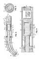
- FIG. 1is a side view of a light device incorporating features of the present invention.
- FIG. 1Ais a perspective view of a light device in a charging base.
- FIG. 2is an exploded cross-sectional view of the light device of FIG. 1 .
- FIG. 2Ais an enlarged view of a portion of FIG. 2 .
- FIG. 3is a side cross-sectional view of the light device of FIG. 1 showing the tip structure engaging the housing.
- FIG. 4is a partial cross-sectional view of an alternative embodiment of the light device of the invention.
- FIG. 5is a plan view of an end cap structure for a tip structure of the invention.
- FIG. 6is a circuit schematic for a charging circuit to be used to charge the invented light device.
- FIG. 7is a graphical depiction of the curve for operation of the circuit of FIG. 7 .
- FIG. 8is a graphical depiction of the charging of the ultracapacitors according to an embodiment of the invention.
- FIG. 9Ais a graphical depiction of a capacitor charging curve.
- FIG. 9Bis a graphical depiction of a capacitor discharging curve.
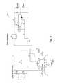
- FIG. 10is a circuit schematic showing a power supply current source circuit for one embodiment of the invention.
- FIG. 11is a circuit schematic showing a power supply current source circuit for another embodiment of the invention.
- FIG. 12is a circuit schematic showing a power supply current source circuit for another embodiment of the invention.
- FIG. 13is a circuit schematic showing a power supply current source circuit for another embodiment of the invention.
- FIG. 14is a graphical depiction of a discharge function according to an embodiment of the invention.
- FIG. 15is a circuit schematic showing a power supply current source circuit for another embodiment of the invention.
- FIG. 16is a circuit schematic showing a power supply current source circuit for another embodiment of the invention.
- FIG. 17is a perspective view of an alternative embodiment of a light device in a charger base.
- FIG. 18is an exploded view of a charger base in accordance with the embodiment of FIG. 17 .
- FIG. 19is a perspective view of a plug of the charger base in accordance with the embodiment of FIG. 17 .
- FIG. 20is an exploded view of a light device in accordance with the embodiment of FIG. 17 .
- FIG. 21is a sectional view of the light device in accordance with the embodiment of FIG. 20 .
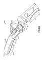
- FIG. 22is an exploded view of a removable tip for a light device in accordance with the embodiment of FIG. 20 .
- FIG. 23is an exploded view of a socket for a light device in accordance with the embodiment of FIG. 20 .
- FIG. 24is a partial cross-sectional view of the socket for a light device in accordance with the embodiment of FIG. 20 .
- FIG. 25is a cross-sectional view of the light device in accordance with the embodiment of FIG. 20 .
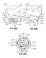
- FIG. 26is a partial cross-sectional view of a light engine for a light device in accordance with the embodiment of FIG. 20 .
- FIG. 26Ais a perspective view of the light engine for a light device in accordance with the embodiment of FIG. 20 .
- FIG. 26Bis a side view of the light engine for a light device in accordance with the embodiment of FIG. 20 .
- FIG. 26Cis a top view of the light engine for a light device in accordance with the embodiment of FIG. 20 .
- FIGS. 27-27Gare circuit schematics for a charging circuit in the charger base in accordance with the embodiment of FIG. 17 .
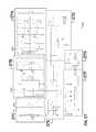
- FIGS. 28-28Care circuit schematics for a main control circuit for a light device in accordance with the embodiment of FIG. 20 .
- FIGS. 29-29Dare circuit schematics for a discharge circuit for a light device in accordance with the embodiment of FIG. 20 .
- FIG. 1illustrates one embodiment of a light device 10 of the present invention. While one embodiment of light device 10 might be used for curing, other uses are also anticipated, such as illumination, tooth whitening, or other treatment applications. Thus, the present invention is not limited to the particular use described herein for an exemplary embodiment.
- Curing device 10includes the housing 12 and a tip structure 14 that is removably coupled to the housing 12 . In accordance with one aspect of the invention, as discussed further hereinbelow, the tip structure 14 may be removed so that it may be separately autoclaved from the overall device.
- Device 10also includes suitable control electronics 16 (See FIG. 2 ) with external controls 18 that may include buttons, switches, or other suitable manual controls for controlling device 10 .
- a display device 20might also be utilized and may include a screen, individual light elements, or other graphical elements for providing a visual display of the operation of device 10 .
- the operational mode or setting of the device, the selectable curing times, the remaining curing time, the charging or power status, and diagnostic graphicsmight also be illustrated utilizing a visual display 20 .
- the tip structure 14includes a proximal end 22 that is removably coupled with housing 12 , and a distal end 24 , which is placed within the mouth of a patient for curing a light-curable compound, in accordance with the invention.
- the base 26 of housing 12might be coupled to a suitable external power supply, such as an AC or DC source in the form of a charging base or dock 27 , as shown in FIG.
- Base 26might also be configured to fit within a suitable structure, such as a standalone, table-mounted base, a mounting structure for mounting it on a wall, pole, or chair, or might be incorporated in a portion of a dental chair for holding and charging the curing device 10 .
- FIGS. 2 and 2Aillustrate cross-sectional views of device 10 , showing the interface between the tip structure 14 and housing 12 .
- FIG. 3illustrates the tip structure 14 engaging the housing.
- section lines 30are shown indicating a removable portion of the housing 12 for illustrative purposes.
- the housing 12as well as the tip structure 14 , may be sized as appropriate for a hand-held curing device that may be manipulated to position the distal end 24 of the device in the mouth of a patient, or otherwise proximate to light-curable material and compounds.
- Tip structure 14includes a heat sink structure or element 32 that extends in the tip structure from the proximal end 22 to the distal end 24 .
- the heat sink 32extends past the proximal end 22 of the tip structure 14 to engage the housing 12 for appropriate thermal transfer of heat from a curing light device.
- the heat sinkmay be made from a suitable heat-transfer or heat-conducting material, such as a metal (e.g. copper) or aluminum.
- a high thermal conductivity materialsuch as Pyrolytic Graphite sheets (PGS) might be used for heat sink 32 .
- the heat sink 32is an elongated copper tube formed in an appropriate shape for positioning inside the tip structure 14 .
- Suitable thermal insulation material 34surrounds the heat sink 32 .
- Tip structure 14includes a body 36 that houses the elements of the tip structure, and is appropriately sealed at its proximal and distal ends 22 and 24 , as discussed further hereinbelow.
- the body 36is made from an autoclavable material in accordance with one aspect of the invention. As noted above, it is desirable to sterilize certain reusable dental elements, such as those that are used in or inserted into or onto or proximate to the mouth of a patient. Past curing light devices have not been autoclavable to the degree desired by dental professionals.
- the present inventionprovides the tip structure enclosed within a sealed body 36 made from an autoclavable material that is able to withstand high temperature autoclaving, such as above 121° C., thus making the entire tip structure, including the light-emitting device or engine therein, autoclavable as well.
- the autoclavable body 36is formed of a suitable metal, such as stainless steel.
- the body 36might be formed of a ceramic, glass, or porcelain material that is able to withstand the temperatures associated with autoclaving.
- the body 36will be formed to a suitable shape in conjunction with the heat sink 32 and insulation material 34 .
- the heat sink 32 and insulation material 34might be formed and the body 36 then formed by coating with the ceramic, glass porcelain, polymeric, or other autoclavable material.
- the tip structure 14is appropriately curved from manipulation at a curing site, such as the mouth of a patient, and thus, the body 36 is formed in a curved fashion as well.
- a light-emitting devicemay include one or more LED elements that are known for curing light-curable compounds, such as dental compounds, and are available from various manufacturers.
- High power LED elementsare one suitable type of elements for the inventive device.
- a high-power dental LEDmight be used.
- the light-emitting enginemight use a single LED element or a plurality of elements in an array.
- the light-emitting devicewill emit a light in a particular desired wavelength for curing a light-curable compound.
- a suitable lightis in the wavelength range of 370-500 nanometers, or the blue light range.
- other uses of the inventive lightsuch as for examination of the oral regions to detect caries, illuminate areas, and provide cancer screening, other wavelengths might be used.
- various different tip structures 14may be readily removed and inserted into the housing 12 so that multiple different tip structures might be utilized with a single housing 12 .
- the light-emitting devices of the various tip structuresmight be directed to other applications, such as to whiten teeth, or for illumination within the mouth of a patient, but would still be operated with the same housing 12 and its controls.
- the present inventionis not limited to a specific type of lighting device or use, and various different tip structures 14 might be utilized with light-emitting devices that emit light in an appropriate range of wavelengths for different uses, such as curing, whitening, illuminating, screening, etc.
- Such light-emitting devices or light engine 40generally include a base or substrate 42 that supports one or more light-emitting structures, or semi-conductor junctions, such as in the form of light-emitting diodes or LEDs.
- a single light-emitting structuremight be utilized or an array of structures might be arranged on substrate 42 for providing device 40 , depending upon the power of the structures or elements.
- High power LED elementsmay be used for example.
- the light-emitting device 40is able to withstand high temperatures, and thus, utilizes high-temperature structures, or LED's.
- Substrate 42is adhered directly to the distal end of heat sink 32 utilizing a high-temperature adhesive or cement. The direct coupling of the light-emitting device 40 to the heat sink 32 provides optimum thermal coupling for removal of the heat generated by the light-emitting structures 44 or substrate 42 .
- a glass window 46 or other transparent elementis solder-sealed around its periphery to housing 36 , as shown in FIGS. 2 and 3 .
- the transparent elementis configured to allow light to pass out of the distal end of the housing.
- the glass window 46might include metalized portions around its periphery for proper solder-sealing to the housing 36 utilizing a high-temperature solder, or other appropriate high-temperature adhesive.
- the light-emitting device 40operates with a lens 48 over the LEDs or other light-emitting structures in order to focus the light from those structures.
- a window 46is illustrated in FIG. 2 .
- a separate lens 48might be sealed to the end of the housing 36 instead of a window 46 .
- the lens 48may be appropriately shaped for focusing light from light-emitting device 40 .
- a total internal reflective (TIR) lensmight be used, as discussed further hereinbelow for the lens 48 .
- the present inventionutilizes high-temperature flexible circuits, or flex circuits 50 , 52 .
- the flex circuitsextend generally along the inside of the tip structure proximate the heat sink 32 .
- the flex circuitsare flexible, and thus, may follow the contour or shape of the heat sink 32 .
- suitable traces or channelsmight be formed in the heat sink 32 for placement of the flex circuits 50 , 52 .
- the flex circuits 50 , 52couple to a ceramic end cap 54 , with suitable electrically-conductive elements, such as traces, thereon for coupling to the flex circuits, and ultimately to a power supply and control circuits, as discussed further below.
- the proximal end 22 of the tip structure 14is sealed utilizing a ceramic end cap 54 that has rotational circuit traces 56 , 58 formed therein, as illustrated in FIG. 5 .
- the tip structure 14is rotatably coupled with housing 12 .
- device 10 of the inventionincorporates circular electrically-conductive elements or circuit traces 56 , 58 formed on or in the end cap 54 .
- the circuit traces 56 , 58generally follow the shape of the end cap, and have a generally circular shape.
- end cap 54has an appropriate center opening 60 formed therein for passage of the heat sink 32 , as illustrated in FIG. 2A .
- the innermost circuit trace 56is illustrated is being electrically-coupled to the flex circuit 50 .
- the outer circuit trace 58 on the end cap 54is coupled with flex circuit 52 .
- End cap 54may be a ceramic end cap of a suitable ceramic material, such as aluminum oxide. The ceramic cap may be adhered to the body 36 . If the body is metal, the edge of ceramic cap 54 may be metalized for soldering the cap to the end of the body. Alternatively, if the body is made from glass, a suitable high-temperature adhesive might be utilized to couple the end cap to the glass body.
- the metal traces 56 , 58are formed through end cap 54 to present a connection for the flex circuits at the distal end of the tip structure.
- the flex circuits 50 , 52 via the ceramic end cap 54are coupled to a suitable power supply circuit and controls.
- spring contacts 62 , 64are mounted at the end of housing 12 that interfaces with tip structure 14 .
- Those spring contacts 62 , 64are coupled through appropriate connections or circuits 66 , 68 back to a suitable power supply circuit 28 .
- the supplied powermay then be controlled via suitable control circuit 16 , such as to control the intensity of the light-emitting device, the duration of its illumination, and various other parameters associated with the operational modes of device 10 .
- Housing 12contains suitable control circuitry 16 and a power supply circuit 28 , along with the various electrical connections/circuits 66 , 68 for powering the tip structure 14 and the light-emitting device 40 at its distal end.
- Power supply circuit 28through contacts 70 may be coupled to an external supply of power, such as an AC source or a DC source, for charging elements of the power supply.
- a base 27might hold or dock device 10 for recharging purposes.
- the power supply circuitincludes rechargeable supply elements, such as a battery, which may be charged and removed from the external power source to be manipulated by an operator.
- rechargeable supply elementssuch as a battery
- an ultracapacitor element or circuitmight be utilized to provide the desired power for the light-emitting device 40 .
- Housing 12may be formed of any suitable material, such as plastic or metal, or some other rigid material.
- the contacts 62 , 64engage the circuit elements or traces 56 , 58 respectively in the end of the tip structure. This electronically couples the light-emitting device with the power supply circuit. Because of the unique circular pattern of the traces, the tip structure 14 may be rotated in a range of 0°-360°, while the contacts 62 , 64 still maintain connection to the traces 56 , 58 . Alternatively, the circular conductive element might only be contacted over some circular range less than 360°, but still allow at least partial rotation. In that way, the tip structure may be rotated without jeopardizing the electrical connection between the housing 12 and the tip structure 14 .
- the electrically-conductive elements 56 , 58are illustrated as formed on the tip structure and the contact elements 62 , 64 , as positioned on the housing, their relative position might be reversed with elements 56 , 58 on housing 12 and elements 62 , 64 on tip structure 14 . That is, the electrically-conductive elements or traces 56 , 58 and contact elements 62 , 64 may be positioned on either of the opposing housing and tip structure to pass power between the two. In an alternative embodiment, alternate pins and sockets might be used between the housing and tip structure to electrically couple the light-emitting device and power supply circuit.
- the proximal end of the heat sink 32engages a suitable channel 80 formed in housing 12 .
- the channel 80is formed by an additional or secondary heat sink structure or element 82 , which is preferably formed of a suitable metal, such as aluminum.
- the heat sink 82includes a reservoir portion 84 , which contains additional heat sink material. That reservoir portion might be all metal to form a metal heat sink.
- the reservoir portion 84might be made of metal, but then contains an amount of phase change material 86 .
- Phase change materialabsorbs the heat from the secondary heat sink structure 82 , and changes phase upon such absorption.
- one suitable phase change materialmight be a paraffin wax that melts as it absorbs heat.
- phase change material 86might also be contained within the reservoir portion 84 of the secondary heat sink structure 82 , and thus, the present invention is not limited to a particular phase change material 86 .
- the heat sink 32engages the secondary heat sink structure 82 such that the end of the heat sink 32 is inserted into channel 80 to provide direct thermal connection or coupling between the heat sink 32 and the secondary heat sink structure 82 .
- the metal of the secondary heat sink structure 82may absorb the heat conducted by heat sink 32 . If the reservoir portion 84 is simply solid metal or filled with a metal material, that metal would absorb heat, and thus, keep the temperature of the light-emitting device at a suitable operating point.
- phase change material 86fills reservoir 84 , the phase change material may melt in its absorption of heat, and thus, change phase to keep the operating point at a suitably low temperature.
- the circuits 66 , 68are high temperature circuits, and thus, will be suitable in their proximity to the secondary heat sink structure 82 .
- a jacket of insulation 88might surround a proportion of the secondary heat sink structure 82 , such as the reservoir portion 84 , and may also surround suitable electronic elements, such as the power supply circuit 28 , and portions of the contacts 70 in order to protect them from the heat of the second heat sink structure 82 .
- Solid-liquid phase change materialsabsorb heat, and their temperature rises to a point where they change phase (their melting point). The materials then absorb additional amounts of heat without getting significantly hotter.
- the phase change material 86solidifies, and thus, releases its stored heat. Therefore, the phase change material absorbs and emits heat while maintaining a generally constant temperature, which is desirable for the hand-held housing 12 .
- phase change materialis paraffin wax loaded with carbon.
- the spring-loaded nature of the spring contacts 62 , 64provides a consistent and robust electrical connection between housing 12 and the tip structure 14 .
- the power supply circuit 28incorporates one or more ultracapacitors or super capacitors to provide the power for supplying the light-emitting device in the tip structure 14 .
- the one or more ultracapacitors 90could be utilized to replace batteries in the power supply circuit 28 .
- the ultracapacitorsprovide high-energy storage, and are able to deliver power instantly when called upon, such as to power the light-emitting device.
- the ultracapacitorsalso charge very rapidly, sometimes in seconds, using the charging or charger circuits described herein in accordance with aspects of the invention. They can also be used to provide a necessary sudden burst of energy for applications of the device 10 of the invention.
- the rapid charging time provided by the power supply circuit 28 of the inventionprovides quick-charge applications, and eliminates the need for rechargeable batteries, which may require hours to fully charge. Furthermore, ultracapacitors have greater useful life. While a NiMH battery might be charged 500 cycles, or a Li-Ion battery 300 cycles, the present invention uses ultracapacitors that might be charged 500,000 cycles. Furthermore, such ultracapacitors that are charged and discharged as described herein do not have a memory (like battery units), have a reduced weight and cost, and do not yield hazardous waste upon disposal. For example, NiMH and Li-Ion batteries weigh significantly more on average than ultracapacitors.
- a device 10may be coupled to a suitable external power source, such as in a power base or dock 27 with sufficient contacts to engage the contacts 70 of device 10 ( FIG. 1A ).
- the ultracapacitors 90may be charged and then discharged over a series of use cycles, such as curing cycles, for the device 10 .
- the devicemay then be replaced into its charging base, or dock, to recharge the ultracapacitor.
- the ultracapacitor elementswill not need replacement during the lifetime of the device 10 , as would batteries. Since the ultracapacitors 90 charge very rapidly, the down time between charging cycles for a device 10 is very short. For example, while a NiMH battery or Li-Ion battery might take around 2.5 hours to charge fully, an ultracapacitor, as charged in accordance with the circuits of the invention, might be fully charged in 15 seconds.
- FIG. 6is a circuit schematic of one possible charging or charger circuit to be utilized within the base unit or dock 27 for charging device 10 and particularly for charging the ultracapacitors that would be provided in one such embodiment of the invention.
- Charger circuit 100includes a power supply circuit/component 102 that provides suitable DC power to the circuit.
- the power supply 102may be coupled with an appropriate AC power cord 104 for plugging into an AC outlet, and provides DC power within the range of 5-24 Volts, for example.
- An indicator LED 106might be used to provide an indication that the base 27 has power. (See FIG. 1A .)
- base 27might also include indicators 111 , 113 for indicating that device 10 is charging or fully charged.
- Circuit 100is configured to operate as a current source in the form of a current foldback circuit, in accordance with one embodiment of the present invention.
- the current foldback circuit 100is utilized to charge the ultracapacitor power supply circuit 28 of the invention, and provides a desirable rapid charge of the ultracapacitor elements 90 that differs from over how the capacitor might be charged generally.
- a current sourceis utilized to charge the ultracapacitor elements 90 .
- FIGS. 9A and 9Billustrate typical charge and discharge curves for a regular capacitor.
- FIG. 9Ashows a charge curve
- FIG. 9Bshows a discharge curve.
- the charge and discharge curves of a capacitorare considered to be exponential, as illustrated in FIGS. 9A and 9B .
- a single time constant, or 1Tindicates the amount of time that it takes for a capacitor to charge generally to around 63% of its full charge.
- the time for a full chargeis expressed as 5T, as may be seen in FIG. 9A .
- FIG. 9Bshows the discharge curve that is also exponential, wherein the time constant 1T is indicative of the time it takes to discharge to about 37% of its full charge.
- a current source power supply circuit 100is used to charge the ultracapacitor at the desired rate.
- the inventionprovides a rapid, generally non-exponential charge function for the ultracapacitor.
- FIG. 8illustrates a charging ultracapacitor voltage versus time for the charger circuit of FIG. 6 , and it may be seen that a very steep linear slope and charging is provided by the invention for providing a linear change function, as shown in FIG. 6 . This provides significant advantages for the invention.
- circuit 100acts as a linear power supply with a current foldback function.
- FIG. 7illustrates a curve associated with the operation of a current foldback supply, as illustrated in FIG. 6 .
- Charger circuit 100utilizes a linear adjustable voltage regulator 108 , such as an LM1084IT regulator available from National Semi-Conductor.
- regulator 108is a standard linear regulator where the control feedback signal is controlled by the transistor Q 1 voltage Vbe.
- the currentthrough the charging ultracapacitor elements coupled to a connector 109 , develops a voltage across sensing resistors (R 3 /R 4 ).
- the currentis generally or effectively 0 Amps.
- the constant power charging topologygenerally transfers all the available power from the charging source or base into the energy storage ultracapacitors.
- the straight linear constant current or power deliverycan generally provide a recharge of the power supply of the invention faster than 1T versus having to wait up to 5T, as with conventional charging of a capacitor. Effectively, the practical charge time will be set by the maximum peak current that the ultracapacitors can accept.
- FIG. 6illustrates a charger circuit 100 that is a linear constant current foldback power supply
- another alternative embodiment of the invention for fast ultracapacitor chargingis to use a switched mode current mode power supply with pulse limit and pulse-by-pulse limit.
- a lithium Ion (Li-Ion) battery chargermight be utilized.
- a nickel metal hydride (NiMH) battery chargermight also be utilized for the purposes of charging the ultracapacitors.
- the ultracapacitor element or elementshas a capacity of around 150 Farad. A range of 50-1,000 Farad might be suitable for the purposes of the invention.
- a multi-layer ultracapacitormight be utilized, such as one from Illinois Capacitor.
- ultracapacitors made from carbon nanotubesmight also be utilized.
- an ultracapacitor made from carbon aerogelmight be used.
- Lithium Ion ultracapacitorsmight also be utilized and provide significant cycling (e.g., 100,000 cycles) with a very low self-discharge characteristic. Another desirable feature of ultracapacitors is that they may be smaller, thinner, and lighter than conventional power supplies, such as rechargeable batteries.
- the device 10is utilized for curing dental compounds.
- the LEDs that are used for the light device or engine 40are generally high-power blue LEDs, such as an array of such LEDs.
- Such devicesare generally current devices, and the light output from the LEDs is a direct function of the current provided from the power supply.
- the current to the LED elements or array 40should be constant.
- FIG. 10illustrates one embodiment of a suitable buck-boost converter 200 for use in an embodiment of the invention.
- the embodiment illustrated in FIG. 10illustrates two ultracapacitors C 1 , C 2 .
- a single ultracapacitormight be utilized.
- more than two ultracapacitorsmight be utilized to realize the invention, as discussed below.
- the present inventionis not limited to any particular number of ultracapacitors that might be utilized in the power supply.
- Power supply circuit 200utilizes a PWM integrated circuit U 1 .
- U 1is coupled with inductor L 1 and provides power to one or more LEDs.
- FIG. 10illustrates symbolically a single LED 1 , however, such a symbol also covers an array of multiple LEDs.
- PWM circuit U 1provides power through a current sensing resistor R 3 .
- the power supplymight be controlled through an ON/OFF switch S 1 coupled with a suitable control circuit U 3 , which provides ON/OFF control and timing functionality for the operation of the LEDs and the light device.
- Circuit U 4provides a local power supply for the U 3 control circuit.
- circuit U 2In order to control U 1 as a current source in the present invention, circuit U 2 , such as an operational amplifier, converts the current through the LED, sensed by resistor R 3 , into a feedback voltage. The feedback voltage is used to control the U 1 circuit as a current source, as desired. Resistors R 1 and R 2 set the voltage feedback level to the U 2 circuit.
- a buck converter power supply 300might be utilized to provide a constant power load on the ultracapacitors and provide a constant current to any LED element.
- a buck converter topologyas illustrated in FIG. 11 , somewhat resembles the buck-boost topology, as set forth in FIG. 10 with like elements sharing like reference numerals.
- the power path from the PWM circuit U 1includes a Schottky diode element D 1 and inductor L 1 , as illustrated.
- the buck converter circuit 300might be utilized if the LED light engine voltage requirement is less than the ultracapacitor stack voltage.
- a boost converter topologymight be utilized.
- the boost converter circuit 400as illustrated in FIG. 12 , might be used to drive the LED light engine.
- FIG. 12resembles FIG. 10 , with like reference numerals being utilized for like elements.
- a solid state switch Q 1provides the functionality to turn the power supply ON/OFF based on the control of switch S 1 .
- Such a switch Q 1might also be desirable for circuits 200 and 300 as well.
- Schottky diode D 1 and inductor element L 1are coupled appropriately for the boost converter operation.
- PWM circuit U 1can be a standard buck, boost, or buck-boost PWM circuit that can operate at low voltages, such as from 1.5 Volts to 12 Volts.
- the U 2 circuit elementis utilized to control the voltage feedback to the PWM U 1 to provide the current source function.
- the voltage across the R 3 elementis directly proportional to the current through the LED, and the error amplifier amplifies the small voltage drop across the low Ohm sensing resister R 3 to equal the internal PWM reference voltage.
- the U 3 circuitis a control circuit that controls the ON time of the light engine and the shutdown when the ultracapacitor has discharged to a point that is too low for use by the PWM circuit U 1 .
- the U 3 circuitcould be a microprocessor, microcontroller, complex programmable logic device (CPLD), or a simple analog timer, such as a ZSCT1555.
- the U 4 circuitis a charge pump power supply that acts as a low power buck-boost controller, and provides a stable, constant supply voltage to the control circuit during the discharge of the ultracapacitor.
- the Q 1 circuitacts as a solid state switch to disconnect the LED power supply from the ultracapacitors when the power supply is turned OFF.
- the power circuit 400 illustrated in FIG. 12utilizes the Q 1 element.
- Such a solid state switch Q 1may or may not be necessary with the buck converter of FIG. 11 or the buck-boost converter of FIG. 10 .
- Inductor element L 1is an electronic element required for the switched power mode power supply (SMPS). The value of L 1 could range generally from 1 ⁇ H up to 300 ⁇ H.
- the D 1 elementas noted above, is a Schottky diode that generally would be utilized for the buck or boost converter configurations of FIGS. 11 and 12 .
- FIG. 15illustrates and alternative current source for powering the LED light engine in accordance with an embodiment of the invention.
- FIG. 15illustrates a flyback current source 600 , wherein similar elements are used, as noted above, with respect to other embodiments.
- T 1indicates a flyback transformer and element Q 2 illustrates a flyback switch, wherein resistor R 4 is a current limit sensing resistor for switch Q 2 .
- resistor R 4is a current limit sensing resistor for switch Q 2 .
- the switch Q 2when the switch Q 2 is ON, the primary of the transformer T 1 is directly connected to the input voltage source. The voltage across the secondary winding is negative, so the diode D 1 is reverse-biased (i.e., blocked).
- the output capacitorsupplies energy to the output load, such as LED 1 .
- the switchis OFF, the energy stored in the transformer is transferred to the output of the converter.
- the feedback signal from the current sensing resistor R 3is sent back to the PWM circuit U 1 to control the LED current
- FIG. 16illustrates another alternative current source in the form of a “single-ended primary inductor converter” (SEPIC) converter 700 .
- SEPICsingle-ended primary inductor converter
- a SEPIC converteris a type of DC-DC converter that allows the electrical voltage at its output to be greater than, less than, or equal to, that of its input.
- the output of the SEPIC converteris controlled by the duty cycle of the U 1 circuit from the feedback signal from current sense resistor R 3 that is sent back to the U 1 PWM circuit to control the LED current. Similar references are used in FIG. 16 as used in FIGS. 10-13 and 15 .
- Q 1is a solid state switch that turns the power supply ON/OFF.
- the split inductors L 1 and L 2provide the boost function (L 1 ) and the buck function (L 2 ).
- Capacitor C 4provides AC coupling in the circuit of FIG. 16 .
- FIGS. 10-13 , 15 , 16illustrate two ultracapacitors C 1 and C 2 in series
- a single ultracapacitormight be utilized, as noted above.
- the ultracapacitors C 1 , C 2might be connected together in parallel.
- more than two ultracapacitorsmight be utilized, and they might be coupled together in a series-parallel arrangement to provide the required voltage and power for the light device 10 .
- Circuit 500 in FIG. 13is in the form of a boost converter, which is powered by ultracapacitors C 1 , C 2 .
- a voltage detector portion of the circuitprovides power to a “Ready” LED (See FIG. 1A ) to indicate that the light device 10 is fully charged.
- An ON/OFF switch portionpowers a timer circuit, which drives a solid state switch Q 2 to turn the power supply ON and OFF after a selected period of time (e.g., 5-40 seconds).
- a boost converterthen provides the necessary power to an LED or LED array as shown.
- FIG. 17illustrates another embodiment of the invention incorporating various of the features and aspects disclosed here.
- Curing light system 1000incorporates a curing light device 1002 that is shown plugged in a charger dock or base 1004 .
- Charger base 1004and the charger electronics therein, are coupled by a power connector cord (not shown) to an AC power supply, such as a wall outlet.
- the power connector cordincludes an AC-to-DC converter, including appropriate transformer and inverter circuitry that provides a suitable and usable DC signal, such as a 12-Volt DC signal, to the charger base 1004 .
- Charger base 1004has an appropriate opening 1006 therein to hold an end of the light device 1002 , as shown in FIG. 17 .
- Charger base 1004is configured to sit on a flat table or countertop surface.
- the charger baseincludes an appropriate indicator 1008 that is illuminated for indicating the charging status of a light device.
- Charger base 1004also includes a radiometer sensor for measuring the light output of the light device 1002 .
- the radiometer sensoras shown in FIG. 17 , includes an input port 1010 , and a plurality of indicator lights 1012 .
- the output end of the light device 1002may be placed adjacent to the input port 1010 , and operated to output a beam of light.
- a reading by the indicators 1012provides an indication of the power level of the output of the light device.
- light device 1002will output a power level in the range of 1,100-1,800 mW/cm 2 .
- the multiple indicatorsare illuminated in a graded fashion to provide a relative indication of that light output, as discussed below.
- a radiometer sensor 1010has a plurality of indicator lights 1012 that provide a graded indication of the power of the light generated.
- five indicators lightsare used as shown in FIG. 17 .
- the lightshave different colors, and are illuminated in sequence to indicate the intensity of the light generated.
- the curing time interval for the lightis set to a 10 second cycle, as discussed below. Holding the tip over the radiometer sensor 1010 during the curing cycle, the indicator lights will illuminate from the bottom up, providing a reading of the light intensity.
- the radiometer sensorshould be illuminated until the curing cycle is complete.
- the bottom two lightsare amber in color
- the top three lightsare blue in color.
- the indication lightshave a minimum number that must be illuminated to indicate the light device is operational for a curing cycle.
- at least one blue light(3 lights total) must be illuminated for a proper cure.
- the first lightis illuminated with an intensity of 750 mW/cm 2 and above.
- the second lightis illuminated at 850 mW/cm 2 and above.
- the third light(the first blue light) is illuminated at 950 mW/cm 2 and above.
- the fourth lightis illuminated at 1,050 mW/cm 2 and above, and the fifth light is illuminated at 1,250 mW/cm 2 and above.
- the top indicator lightis sensitive to the Periodic Level Shifting (PLS) of the light device, as noted below, and that will cause a blinking or flickering effect for the fifth light.
- PLSPeriodic Level Shifting
- Charger base 1004includes a center portion 1020 formed out of a suitable thermoplastic, such as a Valox resin, available from SABIC Innovative Plastics of Pittsfield, Massachusetts. Center portion 1020 sits on a metal base 1022 .
- the metal baseis made of a suitable metal, such as a zinc alloy, and weighs 300-320 grams, and in one embodiment, approximately 313 grams.
- the center portion 1020is coupled to the various 1022 by appropriate fasteners, such as screws. Captured between the center portion and base are charger electronics 1024 , which are positioned on an appropriate printed circuit board 1026 .
- the charger electronicsincludes an upstanding charger plug 1028 , which is captured in a suitable upstanding section 1030 of the center portion. Together, the plug and section provide an upstanding charger plug 1028 to be received into the end of the light device 1002 when the light device is seated into the charger base and plugged in, as shown in FIG. 17 .
- an insulator tray 1032is positioned beneath the circuit board 1026 .
- the charger electronicsinclude a suitable outlet 1034 for receiving the plug of an AC/DC power cord, and delivering 12 Volts to the charger electronics 1024 .
- a cover 1036is then placed and appropriately secured to the center portion 1020 to provide the completed charger base 1004 . Screw-in rubber feet 1038 , which are secured with the metal base 1022 , provide suitable engagement with a flat support surface.
- a heavy metal base 1022provides desirable weight to the charger base 1004 to hold the charger base down onto the support surface when the light device 1002 is inserted into and removed from the charger base. This provides the user the ability to readily remove the light device with a single hand, without having to hold down the charger base. The single-handed removal provides a desirable advantage and benefit, and allows the user to readily grab the light device for use with a single hand without upsetting the charger base, or otherwise securing the charger base with the other hand.
- the center portion 1020 and the covermay be formed of a suitable thermoplastic, such as Valox resin.
- Other portions, such as indicator section 1040might be formed of other materials, such as Lexan, a polycarbonate material.
- suitable materialsare used for durability, aesthetics, and other purposes in forming the charger base, as well as the light device.
- FIG. 19illustrates the upstanding charger plug 1028 , which includes suitable charging contacts, such as metal spring-loaded fingers 1042 , for providing suitable electrical contact with the light device 1002 when it is plugged in.
- suitable charging contactssuch as metal spring-loaded fingers 1042
- a socket in the end of the light devicereceives the upstanding charge plug 1028 , as discussed below.
- the spring-loaded charger contactsexert a force on the counterpart contacts of the plug socket 1081 in the body 150 to hold the device in the charger base and provide a robust and positive electrical contact between the device and charger base.
- indicator 1008is illuminated to indicate the charging status of the light device. Different color lights indicate different status. If the light is illuminated in one color, the light device is currently charging.
- indicator light 1008When the indicator light changes to another color, the light device is fully charged.
- indicator light 1008will illuminate in an amber color when the light device is charging, and will illuminate in a green color when the light device is fully charged.
- the light devicewhen the light device is recharged regularly, it will require only 40 seconds of charging for a full recharge. If the power source is fully drained after several days of inactivity, the unit may require up to 70 seconds for a full recharge, but then will again only require around 40 seconds for subsequent recharges.
- the charger baseIn addition to the holding force of the spring-loaded contacts 1042 , the charger base also provides a friction fit of the device 1002 , when it is plugged in for charging. Specifically, a friction fit is presented between the plastic of the upstanding section 1030 , and the plastic material of the plug socket 1086 at the base of device body 1050 . A 4 to 5 Newton point force will be exerted by the charger base contacts 1042 on the body socket contacts (not shown) of socket 1086 at the contact points. However, the additional friction fit presented by the plastic material of section 1030 and plug socket 1086 adds an additional force on the body for a required manual removal force of approximately 7.8 Newtons.
- the charger base 1004provides a weight of approximately 456 grams.
- the metal base 1022weighs around 313 grams, and the other parts and plastic portions provide the rest.
- a charger base weight in the range of 425-475 gramsmight be suitable to provide a one-handed removal. This ensures the removal force required to remove the curing light is less than the downward gravity force provided by the charger base.
- the curing light device 1002includes a hand piece or body 1050 , and a removable LED light attachment referred to herein as tip 1052 .
- the bodyis manually manipulated by a user, such as a dentist.
- the tipis plugged into the body, as illustrated in FIG. 20 , and may be readily removed for changing or replacing the tip.
- Tip 1052may also be rotated as appropriate for positioning the tip and the light therefrom at the curing site or other site.
- the light devicealso includes a light shield 1054 that is held onto the body 1050 by a rubber grommet 1056 .
- the light shieldis made of a suitable plastic material, such as an orange plastic, and is optically clear.
- the rubber grommetprovides an easy removal of the shield, as desired from the body 1050 , and also facilitates easy rotation of the shield as desired, such as when the tip is rotated.
- the hand piece or body 1050has a handle section 1058 to be grasped by a user, and a suitable control and indicator section 1060 that may be manually manipulated, such as by the fingers of a user, when they are holding the light device body at the handle section.
- the curing light device bodyincludes a proximal end 1062 , which includes a socket for plugging into the charger base, and a distal end 1064 , which also includes a socket 1066 for receiving the removable tip 1052 .
- FIG. 25illustrates a cross-sectional view of curing light device 1002 showing the various components of the light device, as well as sections of the body 1050 .
- Body 1050encloses a power supply for the light device in the form of a plurality of ultracapacitors 1068 .
- Light device body 1050also encloses suitable power discharge electronics and control electronics that are positioned appropriately on a pair of printed circuit boards 1070 , 1072 .
- the ultracapacitors 1068are contained in the handle section 1058 , while the electronics 1070 , 1072 , are proximate the control section 1060 , so that individual control buttons 1074 can interface with the electronics, and may be used to control the light device, such as to start a curing cycle.
- body 1050forms a housing for components of the device and includes an internal frame 1080 , which forms a rigid structure and base for the body.
- the framealso provides a suitable structure for holding the socket 1066 that receives tip 1052 .
- Frame 1080is made of a suitable rigid material, such as aluminum.
- the bodyalso includes an upper subsupport 1082 that cooperates with the frame, and provides structure for securing the boards of circuits 1070 , 1072 , such as with screws 1084 .
- the sub support 1082also supports a plug socket 1086 at the proximal end 1062 of the body, as illustrated in FIG. 25 .
- the socket 1086receives the upstanding plug 1028 and contacts 1042 , when the curing light device is plugged into the base charger, and the socket includes appropriate metal contacts (not shown) to interface with the spring contacts 1042 of the plug in the charger base to deliver power to the ultracapacitors and light device.
- An upper cover 1090 and a lower cover 1092operate with the frame and upper subsupport 1082 for forming the hand piece body 1050 .
- the upper subsupport 1082 and covers 1090 , 1092may be formed of a suitable thermoplastic material, such a Valox resin and/or GLSVersaFlex TPE Alloy, available from PolyOne GLS of Avon Lake, Ohio.
- a suitable thermoplastic materialsuch as Valox resin and/or GLSVersaFlex TPE Alloy, available from PolyOne GLS of Avon Lake, Ohio.
- the body 1050might be formed in various different ways, and thus, the invention is not limited specifically to the materials or arrangement of the various sections and body elements.
- the subsupport 1082 that couples with frame 1080defines the control section 1060 , as illustrated in FIG. 21 .
- the control sectionincludes operational buttons 1074 a , 1074 b for turning the device ON and selecting an operational mode, as well as indicator lights 1094 , such as for indicating the length of the cure process that has been selected, as discussed further hereinbelow.
- FIG. 22illustrates one embodiment of the removable tip 1052 shown in the exploded view. Specifically, FIG. 22 illustrates the structure of removable tip that holds, cools, and supports the LED light engine on the distal end 2000 of the tip. The proximal end 2002 of the tip then plugs into an appropriate socket 1066 , as illustrated in FIG. 20 .
- Tip 1052includes two core or body elements 2004 a , 2004 b , which fit together in a clam-shell fashion, as illustrated.
- the body elementsare formed of an electrically and thermally conductive material.
- the elements 2004 a , 2004 bare formed of copper to provide both the conduction of electrical energy to the light engine at the distal end 2000 , and to also provide thermal conduction for removing and dissipating heat that is generated when the light engine is operated.
- an insulator plate or element 2006is positioned between the conductive body elements 2004 a , 2004 b . Therefore, the body elements are electrically isolated, and may act as the positive and negative conductors, as desired below, to deliver power to the light engine of the device.
- the insulator elementis in the form of a plate structure, and generally has the same cross-sectional shape as the body elements, as shown in FIG. 22 . That insulator element incorporates alignment structures 2007 that cooperate with alignment apertures 2008 in the body elements 2004 a , 2004 b for proper alignment to form the finished tip 1052 , as illustrated in FIG. 20 , for example.
- the core or body elements as shownare solid out near the distal end 2000 , but are also hollowed out along portions of their length, as illustrated.
- the proximal endseach include integral electrical contact structures 2010 , 2012 that are formed with the body elements and are positioned along the length of the tip to be longitudinally offset from each other.
- the electrical contact structures 2010 , 2012provide electrical contact with a power source (ultracapacitors) for the tip, in order to provide electrical power out to the light engine on the distal end 2000 of the tip, as discussed further hereinbelow.
- a power sourceultracapacitors
- the offset contact structures 2010 , 2012provide longitudinally separated and electrically isolated contact points, so that positive and negative contacts presented in the socket 1066 , and coupled with the power supply, may make appropriate electrical contact for providing power to the light engine.
- the insulator element 2006keeps the body elements 2004 a , 2004 b electrically insulated from each other, so that both the positive and negative positions of the signals from the power supply may be delivered from the body 1050 out to the distal end of the tip and the light engine.
- the insulator elementincludes a flat base 2014 that abuts with the ends of the body elements 2004 a , 2004 b .
- Copper body elements 2004 a , 2004 bmight be appropriately plated, such as with a nickel plating.
- a steel disk 2016is also abutted against the base 2014 .
- the steel disk 2016might also be plated with the nickel plating, and provides part of the securement apparatus for the tip 1052 , to secure the tip in socket 1066 , as discussed below.
- thermoplastic material 2018such as Valox resin.
- a plastic material layer 2018will generally follow the surface contours of the elements making up the tip, while still leaving the contact structures 2010 , 2012 exposed for proper electrical contact, as shown in FIG. 20 .
- the light engine utilized in the curing light device 1002is coupled to the distal end 2000 of the tip 1052 .
- the tip 1052might be dimensioned for a length X end to end of approximately 4.10 inches, a length Y of approximately 3.22 inches, and a length Z of approximately 2.58 inches.
- the width of the plug end of the tip Wmight be approximately 0.34 inches, and the width W 2 approximately 0.94 inches, as shown in FIG. 20 .
- Thisprovides a stable base 2013 to tip 1052 that is wider than the proximal end 2002 .
- the distal end 2000 of the tipmight be angled approximately 60° from a longitudinal axis L of the tip.
- FIG. 23an exploded view of the socket 1066 that is positioned at the distal end 1064 of body 1050 is shown.
- the socketincorporates a housing 2020 , a cap 2022 that engages the housing and holds a plurality of spacers 2024 , 2026 therebetween.
- Electrical spring contacts 2028are appropriately held between the spacers and are aligned to physically contact the contact structures 2010 , 2012 in the tip 1052 when the tip is plugged into and secured in the socket 1066 .
- the electrical contactsare in the form of shaped spring contacts that generally surround the inside of the socket roughly 360°.
- the shaped spring contactscreate a plurality of shoulders 2032 that provide desirable physical and electrical contact with the contact structures 2010 , 2012 of the tip. As illustrated in FIG.
- the contacts 2028 and 2030are spaced along the length of the socket to coincide with the longitudinal offset spacing of the contact structures 2010 and 2012 at the proximal end 2002 of the tip.
- a gasket 2023 positioned at an end of the socketengages the subsupport 1080 , as shown in FIG. 24 .
- the tip 1052is secured in socket 1066 with a magnetic mechanism.
- the contact structures 2010 and 2012each are seated to press against their respective electrical contacts 2028 , 2030 . More specifically, the contact structures 2010 , 2012 abut against the shoulders 2032 of those electrical spring contacts.
- the contacts 2028 , 2030 and structures 2010 , 2102are dimensioned to provide a solid electrical contact all the way around the socket.
- a magnetsuch as a magnetic disk 2027
- the magnetic diskmagnetically attracts the steel disk 2016 in the tip proximal end. In that way, the tip is securely yet removably held in the socket 1066 of body 1050 .
- the magnet or magnetic disk 2027is made of a rare earth magnetic material, such as, for example, a Neodymium Iron Boron magnet (NdFeB) that is rated N52.
- a Neodymium Iron Boron magnetNdFeB
- other suitable rare earth magnets rated N28-N52 in their magnetic scale, or 28 MGO e -52 MGO emust be used
- the N52 magnetic diskprovides a strong securement of tip 1052 in the body 1050 . This strong magnetic engagement not only physically secures the tip, but also maintains a strong and robust electrical contact between the proximal end of the tip and the contacts 2028 , 2030 of the socket 1066 .
- the magnetic securement of tip 1052also allows the tip to be freely rotated around the socket, while staying secured in the socket. This provides greater flexibility to the user.
- the magnetic disk 2027creates a pull force in the range of 0.5-6 pounds to secure the tip, and, in one embodiment, a pull force of approximately 2 pounds is provided for securing the tip in the socket.
- the tipcan be readily rotated, but also may be readily removed when desired by manually overcoming the magnetic force.
- the magnetic mechanismis illustrated with the magnetic disk in the socket and the disk is on the tip, the arrangement might be reversed with the magnetic disk on the tip and the disk in the socket.
- the spring contactsextend back from socket 1066 , and contact the appropriate circuits 1070 and 1072 for providing the control for the light device and electrical power to the tip and the LED light engine.
- the body elements of the tip 2004 a and 2004 bwhich are copper in an exemplary embodiment, provide the electrical connection from the electrical spring contacts 2028 , 2030 to the light engine at the distal end 2000 of the tip. That is, electrical current is conducted down the length of the tip and the elements 2004 a , 2004 b .
- the body elements 2004 a , 2004 bare also thermally conductive, and are thermally coupled with the light engine so as to draw heat away from the light engine, and away from the distal end of the tip.
- the heatis conducted away along the length of the tip through the body elements, and is appropriately dissipated through those body elements and through the thermoplastic material layer 2018 .
- the light device 1002 of the inventionremoves the heat and provides a desirable long operating life for the light engine and the LED emitters.
- light engine 2050utilizes a substrate base 2052 with one or more LED emitter devices 2054 positioned thereon.
- an exemplary illustrated embodimentutilizes three LED emitters that form an array.
- the present inventionimplements a light engine with this number of LED emitters in order to provide the curing light output power in the range of 1100-1800 mW/cm 2 , as noted, while at the same time, controlling the heat generated by the light engine.
- the body elements 2004 a , 2004 b of the tipare configured and dimensioned to draw heat away to prevent a significant rise of tooth pulp temperature.
- the three (3) LED emittersensure that the heat generated during a curing cycle does not overheat or burn up the LED emitters, and does not provide heat at the distal end of the light tip that would damage the tissue of a tooth being cured. More specifically, the combination of the three LED emitters and the configurations and dimensions of the body element 2004 a , 2004 b are their thermal properties ensures that temperature is controlled, and the pulp temperature of a tooth being curing is not raised more than 5 degrees Centigrade.
- LED emitters from CREE, Inc. of Durham, N.C.are utilized. Specifically, suitable CREE LED's in the EZ-900 Series might be utilized.
- C470 EZ-900 emittersare utilized, which have a dominant wavelength 464-468.5 nm, and a radiated flux of 400 mW-420 mW.
- the LED emitters 2054are appropriately physically and electrically secured to base 2052 .
- Base 2052might be an aluminum nitride substrate that provides electrical isolation, as well as good thermal conductivity.
- Base 2052is then electrically adhered to the distal end 2000 of the tip 1052 .
- Suitable positive and negative electrical connectionsare provided through the body elements 2004 a , 2004 b of the tip, and thus, suitable electrical connections are provided to the light engine 2050 .
- the base 2052includes contacts 2056 that connect with the two respective body elements 2004 a , 2004 b of the tip.
- the contacts 2056are in the form of tabs that fit into slots 2057 found in the elements 2004 a , 2004 b , as shown in FIG. 22 .
- Such a direct connectionprovides a robust electrical connection, and eliminates the need for any wiring between the tip elements 2004 a , 2004 b , and the substrate.
- the top layer of the substrateincludes suitable microstrip conductors and patterns 2058 , and jumper wires 2060 for coupling the LED emitters 2054 together in a series electrical connection.
- a protective circuit componentsuch as a zener diode 2062 might be utilized between the contacts 2056 on the bottom of base 2052 for protection of the LED emitter elements 2054 , as shown in FIG. 26B .
- the base and LED emitters comprising the light engineare coupled to the distal end 2000 of the tip to provide light directly to the curing site. The light does not have to pass through a long light guide, and thus, the proper amount of light can be provided while generating less heat than curing lights that implement the light engine inside the body of the device and rely upon an elongated light guide.
- the unique tip designwherein the elements 2004 a , 2004 b act as both electrical conductors, as well as thermal conductors, also ensures that sufficient power if delivered to the light engine, while the generated heat is directed away from the light engine, and away from the distal end of the tip.
- a non-imaging lens element 2070is coupled with the light engine. More specifically, the lens element is positioned over the light engine 2050 , and particularly over the LED emitters 2054 , at the distal end of the tip. Lens element 2070 , as illustrated in FIGS. 26 and 26A , has a frustoconical section 2072 and a cylindrical section 2074 . One end of the frustoconical section, and particularly the small diameter end 2076 , is positioned over the LED emitters.
- the frustoconical section 2072then tapers outwardly in diameter along its length to a larger diameter end 2078 , where it continues, at that diameter, as the cylindrical section 2074 .
- the lenshas lengths L of approximately 0.279 inches, and L 2 of approximately 0.219 inches, and a diameter D of approximately 0.320 inches.
- the frustoconical sectionhas a taper angle ⁇ of approximately 42 degrees.
- Lens element 2070is a non-imaging lens element, which collimates the light generated from LED emitters 2054 , and directs that light out of a distal end 2080 of the lens element.
- the lens distal end or face surface 2080generally represents the distal end of the tip 1052 , and ultimately the distal end of the curing light device.
- the distal end 2080is positioned proximate to a work site, such as a site containing dental composite material that is to be cured. Light generated from the LED emitters 2054 is captured and collimated and effectively reflected in the body of the lens element 2070 to be directed out of the distal end 2080 .
- the lens element 2070is a total internal reflector (TIR) lens element that is configured for capturing, collimating, and efficiently directing the light out to the end of the lens element for less optical loss and greater delivery of light energy to the curing cite.
- TIRtotal internal reflector
- a suitable non-imaging lens elementwould be available from Schott North America, Inc. of Elmsford, N.Y.
- the small diameter end 2076might be coated to have a metalized body surface along its periphery, as illustrated in FIG. 26A by circular metal pattern 2081 .
- the substrate forming base 2052includes a metallization pattern 2082 thereon for abutting metal pattern 2081 and the lens element and sealing the light engine 2050 (See FIG. 26C ).
- the small diameter end 2076 of the lens elementalso incorporates a convex indentation 2084 , as illustrated in FIG. 26B .
- the convex indentation at the small diameter end 2076 of the lens elementoverlies the LED emitters 2054 .
- a silicone adhesiveis injected into the convex cavity 2084 , such as through openings or holes 2086 in the base 2052 . More specifically, a suitable silicone adhesive might be injected into one hole, filling the cavity, while air is directed out of the other hole 2086 .
- a suitable silicone adhesivemight be available from Schott North America, Inc. as a UV-200 index matching silicone adhesive. After the silicone adhesive is injected, the holes are then sealed, such as by soldering. Thus, the LED emitters are sealed from the environment, while allowing the radiant energy therefrom to pass through the interface to lens element 2070 .
- the lensmay be further secured in the tip 1052 using an adhesive around the periphery of the lens proximate the distal end 2080 .
- a gap 2083is provided in the tip for such adhesive.
- the end of plastic material 2018is generally flush with the face or distal surface 2080 .
- the light system 1000includes the curing light device 1002 , and charger base 1004 , as discussed herein.
- Appropriate circuitry contained in both the curing light device 1002 and the charger base 1004provides the desirable charging, discharging, and operation of the system.
- the light device 1002incorporates a plurality of ultracapacitors for storing energy to power a light device.
- two ultracapacitors 1068(sometimes called supercapacitors) are charged through charger base 1004 and the circuitry therein, and are discharged to operate the light device 1002 and power the light engine at the distal end of the tip 1052 .
- the appropriate charger circuitryis contained on the circuit board 1026 in the charger base, as illustrated in FIG. 18 .
- the circuitry for turning on the curing light device, changing the operational mode to the curing light device, and other operational featuresare contained on the appropriate circuit boards 1070 and 1072 , as illustrated in FIG. 25 .
- the curing light devicehas several operational curing modes.
- the light devicemay be operated to provide several different curing cycles, including a five-second (5) cycle, a ten-second (10) cycle, and a twenty-second (20) cycle.
- suitable indicator lights 1094as shown in FIG. 21 , provide an indication of the curing light cycle or mode that has been selected.
- Appropriate controls, such as push buttons 1074 a , 1074 bmay be used to turn the curing light device ON and OFF, to select the operational mode and curing cycle, and to begin the curing cycle. When a particular cycle is selected, the curing light will output a light beam for the selected amount of time.
- light device 1002incorporates periodic level shifting (PLS).
- PLSperiodic level shifting
- Such periodic level shiftingprovides an increased light output, while maintaining desirable heat characteristics.
- PLS featureis disclosed further in U.S. Pat. No. 8,113,830, which is commonly owned with the present application, and which is incorporated by reference herein in its entirety.
- the control circuitryprovides the several curing modes of five, ten, and twenty second, with the PLS feature, or without the PLS feature. Accordingly, six operational modes might be selected.
- button 1074 aturns the unit ON and OFF, and also selects or deselects the PLS feature.
- Button 1074 bcontrols the operating mode, and also controls an audible beeper.
- a charge indicator light 1094 aindicates the amount of time for curing that may be provided with the current charge. When there are 40 seconds or less of curing time left, the charge indicator light 1094 a glows amber, warning the user that the charge is almost depleted. The charge indicator light turns red when there is not enough charge to complete the selected curing cycle duration. If the curing cycle duration is reduced, the light may change back to amber, indicating there is enough charge for a shorter curing cycle.
- the three top-most indicator lights 1094indicate the time interval or operational cycle that is selected.
- the selector button 1074 bis pressed until a desired time interval is indicated by a respective illuminated light. That is, curing cycles of 5, 10, and 20 seconds may be selected.
- button 1074 ais engaged to start the curing cycle.
- the PLS featurewill be automatically engaged. With the PLS feature, the LED emitters will appear to be flickering at the end of the tip. If button 1074 a is pressed at any time during the curing cycle, it will stop the curing cycle.
- the PLS featuremay be disabled by pressing and holding button 1074 a , when starting the curing cycle.
- the PLS featurewill be disabled until the button is released.
- the curing lightwill maintain a steady light output of around 1,100 mW/cm 2 , and the unit will beep once per second.
- the curing lightemits a short, audible beep when button 1074 a is pressed.
- the beepindicates that the curing cycle has begun. A slightly longer, audible beep will sound at the end of the curing cycle.
- a beepis sounded every 5 seconds, as well as at the end of the cycle.
- the curing light devicemight also be placed into silent mode by essentially holding down button 1074 b when the curing cycle is being selected.
- the processing circuitryis appropriately configured and programmed for providing the noted operational features and curing cycles.
- FIG. 27a main charger circuit is shown for charging the power supply and ultracapacitors of a light device.
- various circuits and their locationswill be indicated in particular locations, such as either in the charger base 1004 , or in the light device 1002 .
- the main charger circuit of FIG. 27is shown broken up into several sections for the purposes of illustrating greater detail, such as in FIGS. 27A-27G .
- the circuitry of FIG. 27is generally contained on board 1026 , as illustrated in FIG. 18 .
- the charger circuit 2100provides individual charging of two ultracapacitors in a three-point connection charging circuit for more rapid charging. Furthermore, charger circuit 2100 incorporates trickle charge sections for maximum charging. Therefore, the invention provides a very rapid charge of the light device in the order of less than, or around 40 second, so that the light device may be repeatedly used without significant downtime for the purposes of charging.
- the curing light devicebegins immediately charging upon being engaged with the charger base. That is, when the light device is put into the appropriate opening 1006 , and the upstanding plug 1028 is plugged into socket 1086 , the ultracapacitors will begin to charge. Indicator 1008 on the charger base provides an indication that the charge process is ongoing, and when the device is completely charged.
- the ultracapacitorseach have a capacitance value of 100 Farads, and will provide a desirable number of operational cycles when they are fully charged.
- One suitable ultracapacitor for the inventionis available from Maxwell Technologies of San Diego, Calif.
- the power supplyincorporates two 100 Farad capacitors to provide the user with a desirable run time, and desirable large number of operational cycles while still maintaining a rapid charging time.
- the two ultracapacitors, operating together, when fully chargedwill provide a working time or operational run time of at least 1 minute.
- the two ultracapacitors, when fully chargedwill provide an operational run time of up to 10 minutes.
- approximately 250 seconds of run timeare provided by a full charge of the two capacitors. For example, that would provide around 25 individual 10-second curing cycles.
- the inventorshave determined that the two 100-Farad ultracapacitors, that are charged utilizing the unique charging circuit as noted below, will provide a rapid charge of the light device of around 40 seconds, while providing a desirable amount of run time, such as the 250 seconds of run time noted. Therefore, that unique combination of the multiple ultracapacitors and the unique charging circuitry provides desirable features for the curing light device.
- the ultracapacitorsdo not heat up significantly when they are being charged, or when they are being discharged, and thus, do not generate a significant amount of heat that affects their operational life like batteries do. Therefore, a consistent amount of run time may be achieved with each full recharge. Furthermore, the ultracapacitors will last up to 500,000 charging cycles, which provides a significant life to the power supply of the curing light device of the invention.
- the charger circuit 2100includes an input section 2102 , as illustrated in FIG. 27C .
- Input circuit section 2102includes an appropriate DC jack 2104 for plugging into a DC power supply to provide the twelve-volt DC signal.
- a DC power supply(not shown) will generally include an AC plug and suitable converter circuitry to convert AC to DC to the desirable level, such as twelve volts DC.
- the input sectiondelivers twelve volts DC to the main power supply section 2106 , as illustrated in FIG. 27B .
- the main power supply section 2106provides further DC signal conversion, such as down to a level of 5.4 volts DC.
- the main power supply sectionincorporates a suitable converter circuit 2108 to provide the step-down conversion.
- converter circuit 2108may be a 10V/20A constant current, constant voltage step-down converter.
- the main power supply sectionprovides a suitable DC voltage signal to the current source circuit 2120 , which is coupled to the ultracapacitors to charge the ultracapacitors.
- the current source circuit 2120includes sub-circuits 2122 , 2124 , which act as current sources. There is one current source circuit for each ultracapacitor to be charged (two ultracapacitors in the exemplary embodiment).
- the current source circuit 2122 , 2124are then coupled to trickle charge circuits 2126 and 2128 , respectively, for each current source circuit.
- Each of the trickle charge circuits 2126 and 2128provide a top-off of the charge for each of the respective ultracapacitors.
- the current source circuit 2120provides a three-point connection to the series connected ultracapacitors.
- two series connected ultracapacitorshave a top point of connection to the first one of the ultracapacitors, a middle point of connection where each of the ultracapacitors connect to each other, and then a bottom or ground point of connection at the second ultracapacitor.
- the connector 2130as illustrated in FIG. 27A , the top point of connection to a first ultracapacitor is illustrated by circuit trace 2132 .
- Circuit trace 2134is the mid-point connection between the two ultracapacitors.
- circuit trace 2136provides the ground connection to the second ultracapacitor.
- the various current source circuits 2122 , 2124 , and respective trickle charge circuits 2126 , 2128are coupled to each of the ultracapacitors in a three-point connection of traces 2132 , 2134 , 2136 .
- Such a three-point connectionprovides rapid and efficient charging of the ultracapacitors, and also provides a complete charge that is generally equally distributed across the ultracapacitors.
- FIGS. 27D and 27Eillustrate additional operational circuitry that provides the detection of the charging process, as well as an indication of the charging by a photodiode, such as to provide illumination of the indicator 1008 .
- FIGS. 27F and 27Gillustrate control circuitry for providing the desired control of the charging process, including a microprocessor or controller element 2140 , as illustrated in FIG. 27F , and a register circuit 2142 , as illustrated in FIG. 27G .
- FIG. 28illustrates a main control circuit 2200 for a light device 1002 .
- the main control circuitwill be on board 1072 , in the control section 1060 of the light device body 1050 .
- the main control circuit 2200incorporates a control section, which includes a suitable processor or controller 2202 for controlling the operation of the light device.
- the controller 2202interfaces with one or more switches 2204 , 2206 , which are actuated, such as by the buttons 1074 , as illustrated in FIG. 25 .
- the switchescontrol the ON/OFF characteristics of the light device, as well as the modes that are selected for curing.
- the main control circuitfurther includes an indicator section, as illustrated in FIG.
- the LEDsprovide a desirable indication, such as through indicators 1094 to indicate the length of the cutting cycle (e.g. 5, 10, 20 seconds) as well as the particular mode, such as a PLS mode or a non-PLS mode.
- the main control circuitwill also include an appropriate connector 2216 for connecting to a discharge circuit for discharging the ultracapacitors and driving the light engine for a curing process.
- Discharge circuit 2220provides an input section, as illustrated in FIG. 29B , that couples appropriately with ultracapacitors 1068 .
- the ultracapacitorsas illustrated, are discharged in series and generally 5.2 volts DC is provided across the ultracapacitors, which is converted by an appropriate converter circuit component 2222 , to around 3.3 volts.
- the input circuitmay also provide an appropriate audio element, such as a buzzer or beeper 2224 , for indicating the operation of the light device, such as the completion of a curing cycle.
- the appropriate control of the dischargeis provided through a connector section 29 D, which corresponds to the connector section 28 C of the main control circuit 2200 (See FIG. 28 ).
- the output voltage signal from the input section of FIG. 29Bis provided to discharge circuit sections 23 A, 23 C, which are coupled directly to the light engine LED emitters, as illustrated in FIG. 29 .
- the circuit section illustrated in FIG. 29Aincludes a boost converter circuit 2226 to drive the LED emitters of the light engine.
- the boost converter circuit 2226includes an FET driver component 2228 , which drives FET 2230 .
- a solid state switch component 2232as illustrated in FIG. 29C , provides switch control to turn the curing light device ON and OFF.
- a solid state switch component 2232as illustrated in FIG. 29C , provides switch control to turn the curing light device ON and OFF.
Landscapes
- Health & Medical Sciences (AREA)
- Oral & Maxillofacial Surgery (AREA)
- Dentistry (AREA)
- Epidemiology (AREA)
- Life Sciences & Earth Sciences (AREA)
- Animal Behavior & Ethology (AREA)
- General Health & Medical Sciences (AREA)
- Public Health (AREA)
- Veterinary Medicine (AREA)
- Dental Tools And Instruments Or Auxiliary Dental Instruments (AREA)
- Arrangement Of Elements, Cooling, Sealing, Or The Like Of Lighting Devices (AREA)
Abstract
Description
Tdischarge=C(V1−V2)/I
- Where V1 is the full charge voltage and V2 is the lowest operating voltage.
In one embodiment of the invention, the power supply to drive the one or more LED elements or an array making uplight engine 40 could be a boost pulse width modulated (PWM) current source, or a buck PWM current source. Alternatively, a buck-boost PWM current source might be utilized. Also, a flyback current source or SEPIC current source might be used as discussed below. A buck-boost topology would provide a desirable long run time (discharge time) fordevice 10 by providing power to the one or more LED elements when the ultracapacitors are fully charged and the voltage may be higher than the forward voltage necessary for the LED. Such a topology then also provides power to the LED when the charge on the ultracapacitors due to discharge is lower than the forward voltage for the LED. In one embodiment, using two 100 F ultracapacitors, 30-40 discharge curing cycles of 10 second each might be achieved on a single charge, for example.
- Where V1 is the full charge voltage and V2 is the lowest operating voltage.
Claims (19)
Priority Applications (6)
| Application Number | Priority Date | Filing Date | Title |
|---|---|---|---|
| US13/924,439US9072572B2 (en) | 2009-04-02 | 2013-06-21 | Dental light device |
| EP14172118.3AEP2815719B1 (en) | 2013-06-21 | 2014-06-12 | Dental light curing device |
| CN201410277368.2ACN104224349B (en) | 2013-06-21 | 2014-06-20 | Dental light emitting device |
| JP2014127054AJP6407579B2 (en) | 2013-06-21 | 2014-06-20 | Dental optical device |
| US14/790,666US9693846B2 (en) | 2009-04-02 | 2015-07-02 | Dental light device |
| US15/605,270US9987110B2 (en) | 2009-04-02 | 2017-05-25 | Dental light device |
Applications Claiming Priority (3)
| Application Number | Priority Date | Filing Date | Title |
|---|---|---|---|
| US16613009P | 2009-04-02 | 2009-04-02 | |
| US12/752,335US9066777B2 (en) | 2009-04-02 | 2010-04-01 | Curing light device |
| US13/924,439US9072572B2 (en) | 2009-04-02 | 2013-06-21 | Dental light device |
Related Parent Applications (1)
| Application Number | Title | Priority Date | Filing Date |
|---|---|---|---|
| US12/752,335Continuation-In-PartUS9066777B2 (en) | 2009-04-02 | 2010-04-01 | Curing light device |
Related Child Applications (1)
| Application Number | Title | Priority Date | Filing Date |
|---|---|---|---|
| US14/790,666ContinuationUS9693846B2 (en) | 2009-04-02 | 2015-07-02 | Dental light device |
Publications (2)
| Publication Number | Publication Date |
|---|---|
| US20140038124A1 US20140038124A1 (en) | 2014-02-06 |
| US9072572B2true US9072572B2 (en) | 2015-07-07 |
Family
ID=50025831
Family Applications (3)
| Application Number | Title | Priority Date | Filing Date |
|---|---|---|---|
| US13/924,439ActiveUS9072572B2 (en) | 2009-04-02 | 2013-06-21 | Dental light device |
| US14/790,666Expired - Fee RelatedUS9693846B2 (en) | 2009-04-02 | 2015-07-02 | Dental light device |
| US15/605,270ActiveUS9987110B2 (en) | 2009-04-02 | 2017-05-25 | Dental light device |
Family Applications After (2)
| Application Number | Title | Priority Date | Filing Date |
|---|---|---|---|
| US14/790,666Expired - Fee RelatedUS9693846B2 (en) | 2009-04-02 | 2015-07-02 | Dental light device |
| US15/605,270ActiveUS9987110B2 (en) | 2009-04-02 | 2017-05-25 | Dental light device |
Country Status (1)
| Country | Link |
|---|---|
| US (3) | US9072572B2 (en) |
Cited By (13)
| Publication number | Priority date | Publication date | Assignee | Title |
|---|---|---|---|---|
| US20140113243A1 (en)* | 2012-10-24 | 2014-04-24 | Biolase, Inc. | Handpiece Assembly for Laser Treatment Device |
| US20150202032A1 (en)* | 2013-07-23 | 2015-07-23 | Ivoclar Vivadent Ag | Light curing device for dental restoration materials and method of curing dental restoration materials |
| US20150320530A1 (en)* | 2009-04-02 | 2015-11-12 | Kerr Corporation | Dental light device |
| US20170215698A1 (en)* | 2016-01-28 | 2017-08-03 | Dental Wings Inc. | System and method for providing user feedback indications during intra-oral scanning process |
| US9730778B2 (en) | 2009-04-02 | 2017-08-15 | Kerr Corporation | Curing light device |
| USD810293S1 (en)* | 2017-01-20 | 2018-02-13 | Garrison Dental Solutions, Llc | Dental instrument |
| WO2019157327A1 (en) | 2018-02-09 | 2019-08-15 | Ormco Corporation | Orthodontic devices and methods for using those devices |
| US10568726B2 (en) | 2015-08-06 | 2020-02-25 | Transparent Materials, Llc | Photocomposite, light source and thermal detector |
| US20210030518A1 (en)* | 2018-04-13 | 2021-02-04 | Xing Zhou | Oral irrigator with water volume stepless adjustment device |
| USD916658S1 (en) | 2019-04-26 | 2021-04-20 | Shenzhen Chifrog Technology Co., Ltd | Power pack station |
| US11153995B2 (en)* | 2019-04-26 | 2021-10-19 | Shenzhen Chifrog Technology Co., Ltd. | Powerpack station |
| US11490999B2 (en) | 2013-07-23 | 2022-11-08 | Ivoclar Vivadent Ag | Light curing device for dental restoration materials and method of curing dental restoration materials |
| EP4450024A1 (en) | 2023-04-18 | 2024-10-23 | Kulzer GmbH | Radiation device for activating polymerisable dental materials |
Families Citing this family (9)
| Publication number | Priority date | Publication date | Assignee | Title |
|---|---|---|---|---|
| EP2386263B1 (en)* | 2010-05-11 | 2014-02-26 | Bien-Air Holding SA | Lighting module with light-emitting diodes for a surgical or dental handpiece |
| JP5914485B2 (en)* | 2010-09-16 | 2016-05-11 | オゾン・テクノロジーズ・リミテッド | Electronic devices for dentists |
| US9398649B2 (en)* | 2013-04-19 | 2016-07-19 | Iota Engineering Llc | Constant power supply for LED emergency lighting using smart output resetting circuit for no load conditions |
| JP2017533058A (en) | 2014-09-17 | 2017-11-09 | ギャリソン デンタル ソリューションズ,リミティド ライアビリティ カンパニー | Dental curing light |
| KR101535441B1 (en)* | 2014-12-18 | 2015-07-13 | (주)휴레이저 | Laser treatment apparatus with tips |
| EP3106849B1 (en)* | 2015-06-17 | 2018-05-23 | Ivoclar Vivadent AG | Light hardening device |
| US10897150B2 (en)* | 2018-01-12 | 2021-01-19 | Hand Held Products, Inc. | Indicating charge status |
| EP4210626A4 (en)* | 2020-09-10 | 2024-10-09 | Solventum Intellectual Properties Company | AUTOMATIC DENTAL EQUIPMENT MANAGEMENT SYSTEM |
| KR20250071949A (en)* | 2022-09-21 | 2025-05-22 | 쓰리세이프 에이/에스 | Intraoral scanning device having a supply assembly unit |
Citations (592)
| Publication number | Priority date | Publication date | Assignee | Title |
|---|---|---|---|---|
| US2218678A (en) | 1938-05-06 | 1940-10-22 | Scovill Manufacturing Co | Double reflector flashlight |
| US3310358A (en) | 1963-05-01 | 1967-03-21 | Bell Telephone Labor Inc | Conical lens focusing means for tmon modes |
| US3638013A (en) | 1969-04-02 | 1972-01-25 | Fiber Photics Inc | Dental apparatus utilizing fiber optics |
| US3666180A (en) | 1970-09-02 | 1972-05-30 | Sylvania Electric Prod | Dental light |
| US3704928A (en) | 1970-11-09 | 1972-12-05 | Sylvania Electric Prod | Dental light with dichroic and infrared filters |
| US3712984A (en) | 1971-03-15 | 1973-01-23 | Canrad Precision Ind Inc | Instrument for transmitting ultraviolet radiation to a limited area |
| US3733481A (en) | 1970-06-11 | 1973-05-15 | Bausch & Lomb | Fiber optics light source |
| US3755900A (en) | 1972-03-03 | 1973-09-04 | J Friedman | Dental pulp tester |
| US3787678A (en) | 1972-12-13 | 1974-01-22 | R Rainer | Rechargeable battery powered light |
| US3829676A (en) | 1973-08-07 | 1974-08-13 | Kel Lite Industries | Rechargeable flashlight |
| DE2315709A1 (en) | 1973-03-29 | 1974-10-10 | Licentia Gmbh | RADIATION-EMISSING SEMI-CONDUCTOR ARRANGEMENT WITH HIGH RADIATION POWER |
| US3868513A (en) | 1972-12-26 | 1975-02-25 | Dentsply Res & Dev | Ultraviolet radiation projector |
| US3930149A (en) | 1974-05-28 | 1975-12-30 | Sterndent Corp | Variable intensity dental light |
| US3970856A (en) | 1975-05-16 | 1976-07-20 | Cavitron Corporation | Ultraviolet light applicator |
| US4032773A (en) | 1975-12-18 | 1977-06-28 | Halliday & Co., Inc. | Flashlight |
| US4041304A (en) | 1976-01-22 | 1977-08-09 | Samuel Spector | Flashlight |
| US4045663A (en) | 1976-06-16 | 1977-08-30 | James W. Fair | Rechargeable flashlight assembly |
| US4048490A (en) | 1976-06-11 | 1977-09-13 | Union Carbide Corporation | Apparatus for delivering relatively cold UV to a substrate |
| USRE29421E (en) | 1971-05-26 | 1977-09-27 | Texas Instruments Incorporated | Laser system having electronically selectable gain |
| US4080737A (en) | 1975-11-03 | 1978-03-28 | Siemens Aktiengesellschaft | Coupling device for dental handpieces |
| US4112335A (en) | 1975-03-20 | 1978-09-05 | Dentsply Research & Development Corp. | Rapid pulse ultraviolet light apparatus |
| US4114946A (en) | 1976-05-28 | 1978-09-19 | Kaltenbach & Voigt Gmbh & Co. | Medical treatment chair |
| US4114274A (en) | 1976-11-12 | 1978-09-19 | Pelton & Crane Company | Movable power-operated instrument console and treatment chair apparatus |
| US4149086A (en) | 1976-02-23 | 1979-04-10 | Guenther Nath | UV irradiation device |
| US4151583A (en) | 1976-02-05 | 1979-04-24 | Miller Jack V | Flashlight |
| US4184196A (en) | 1975-11-28 | 1980-01-15 | Moret Michel A | Diagnostic lamp, particularly for checking teeth |
| US4185891A (en) | 1977-11-30 | 1980-01-29 | Grumman Aerospace Corporation | Laser diode collimation optics |
| US4186748A (en) | 1978-02-06 | 1980-02-05 | Schlager Kenneth J | Thermographic apparatus for physical examination of patients |
| DE2842938A1 (en) | 1978-10-02 | 1980-04-17 | Roehm Gmbh | METHOD FOR POLYMERIZING BY UV LIGHT |
| US4209907A (en) | 1977-02-01 | 1980-07-01 | Kabushiki Kaisha Morita Seisakusho | Dental treatment chair assembly |
| US4221994A (en) | 1978-11-09 | 1980-09-09 | Demetron Research Corporation | Photo curing light source |
| US4229658A (en) | 1978-08-18 | 1980-10-21 | Dentsply Research & Development Corp. | Xenon light apparatus for supplying ultraviolet and visible spectra |
| US4230453A (en) | 1979-04-11 | 1980-10-28 | Litton Industrial Products Inc. | Light assembly for use with a dental handpiece |
| US4233649A (en) | 1977-09-27 | 1980-11-11 | Peter Scheer | Treatment chair with cool-light lamp for dental medicinal purposes |
| US4245890A (en) | 1979-01-02 | 1981-01-20 | The United States Of America As Represented By The Secretary Of The Army | Gradient index of refraction for missile seekers |
| US4266535A (en) | 1978-04-14 | 1981-05-12 | Les Produits Associes Bpa Sa | Diagnostic lamp |
| US4281366A (en) | 1979-03-08 | 1981-07-28 | Richard Wolf Gmbh | Lighting systems for surgical operations |
| US4280273A (en) | 1978-11-20 | 1981-07-28 | The General Electric Company Limited | Manufacture of monolithic LED arrays for electroluminescent display devices |
| US4298806A (en) | 1978-01-23 | 1981-11-03 | Espe Fabrik Pharmazeutischer Praparate Gmbh | Apparatus for irradiating substances curable by radiation |
| US4309617A (en) | 1979-03-05 | 1982-01-05 | Minnesota Mining And Manufacturing Company | Pulsed radiation source adapted for curing dental restoratives |
| US4325107A (en) | 1980-01-29 | 1982-04-13 | Macleod Richard H | Rechargeable flashlight |
| US4337759A (en) | 1979-10-10 | 1982-07-06 | John M. Popovich | Radiant energy concentration by optical total internal reflection |
| US4348180A (en) | 1979-11-29 | 1982-09-07 | Siemens Aktiengesellschaft | Device for releasably connecting a head part to a handle part of a dental handpiece |
| US4357648A (en) | 1980-02-08 | 1982-11-02 | Kel-Lite Industries, Inc. | Rechargeable flashlight |
| US4360860A (en) | 1977-03-07 | 1982-11-23 | Johnson Hugh G | Self-contained hand held portable lantern-flashlight consisting of a manually operated generator and rechargeable batteries |
| WO1983001311A1 (en) | 1981-10-08 | 1983-04-14 | Chapman, John, Gerald | Improvements relating to light delivery for tumour treatment |
| US4385344A (en) | 1980-08-29 | 1983-05-24 | Dentsply Research & Development Corp. | Visible light apparatus for curing photo-curable compositions |
| USRE31279E (en) | 1972-09-26 | 1983-06-14 | Laser optical resonator | |
| US4391588A (en) | 1980-11-07 | 1983-07-05 | Kabushiki Kaisha Morita Seisakusho | Dental treatment chair |
| US4392827A (en) | 1981-11-04 | 1983-07-12 | Howard Martin | Self-contained root canal heated condenser dental instrument |
| US4398885A (en) | 1981-02-06 | 1983-08-16 | Kaltenbach & Voigt Gmbh & Co. | Dental handpiece |
| US4402524A (en) | 1979-06-07 | 1983-09-06 | Marker-Patentverwertungsgesellschaft Mbh | Battery-charging generator for electronic ski binding |
| US4412134A (en) | 1981-07-15 | 1983-10-25 | Espe Fabrik Pharmazeutischer Praeparate Gmbh | Apparatus for irradiating dental objects |
| US4445858A (en) | 1982-02-19 | 1984-05-01 | American Hospital Supply Corporation | Apparatus for photo-curing of dental restorative materials |
| US4450139A (en) | 1982-05-03 | 1984-05-22 | Solid State Systems, Corporation | Light generating apparatus for curing dental restorative composites |
| WO1984004463A1 (en) | 1983-05-11 | 1984-11-22 | Mta Koezponti Fiz Kutato Intez | Method and device for stimulating biological processes |
| US4522594A (en) | 1983-01-21 | 1985-06-11 | Marvin M. Stark Research Foundation | Light shield for a dental handpiece |
| DE3411996A1 (en) | 1984-03-31 | 1985-10-03 | Kulzer & Co GmbH, 6393 Wehrheim | Irradiation unit, such as a polymerisation apparatus preferably for curing dental plastics |
| US4610630A (en) | 1985-07-17 | 1986-09-09 | Progressive Machine Products, Inc. | Dental instrument stand |
| US4611992A (en) | 1984-11-02 | 1986-09-16 | Oddvin Lokken | Spray guard for dental tool |
| US4634953A (en) | 1984-04-27 | 1987-01-06 | Casio Computer Co., Ltd. | Electronic equipment with solar cell |
| US4666405A (en) | 1983-02-21 | 1987-05-19 | Ericson Dan V | Method and apparatus for polymerising light-hardening dental fillings of class II type composite material |
| US4666406A (en) | 1984-01-13 | 1987-05-19 | Kanca Iii John | Photocuring device and method |
| US4673353A (en) | 1986-05-30 | 1987-06-16 | Nevin Donald M | Apparatus for applying a light-curable dental composition |
| US4682950A (en) | 1985-10-30 | 1987-07-28 | Dragan William B | Device and method of bonding and veneering dental material to a tooth |
| US4698730A (en) | 1986-08-01 | 1987-10-06 | Stanley Electric Co., Ltd. | Light-emitting diode |
| DE3706852A1 (en) | 1986-04-04 | 1987-10-08 | Dai Ichi Kogyo Seiyaku Co Ltd | METHOD FOR PRODUCING ACRYLIC POLYMERS WITH A HIGH MOLECULAR WEIGHT |
| US4716296A (en) | 1982-04-26 | 1987-12-29 | Surgicorp | Apparatus for curing dental restorative composites |
| US4725231A (en)* | 1985-03-27 | 1988-02-16 | Micro-Mega S.A. | Dental-surgeon handpiece with battery lighting |
| US4729076A (en) | 1984-11-15 | 1988-03-01 | Tsuzawa Masami | Signal light unit having heat dissipating function |
| US4733937A (en) | 1986-10-17 | 1988-03-29 | Welch Allyn, Inc. | Illuminating system for endoscope or borescope |
| EP0266038A2 (en) | 1986-10-29 | 1988-05-04 | Kureha Kagaku Kogyo Kabushiki Kaisha | Apparatus for treatment of cancer with photodiode |
| US4757381A (en) | 1987-03-05 | 1988-07-12 | Fuji Optical Systems, Inc. | Means and structure for prevention of cross contamination during use of dental camera |
| US4792692A (en) | 1986-04-03 | 1988-12-20 | Espe Stiftung & Co. Produktions-Und Vertriebs Kg | Dental irradiation apparatus |
| US4794315A (en) | 1988-01-11 | 1988-12-27 | Pittway Corporation | Rechargeable battery-powered device |
| US4810194A (en) | 1987-11-04 | 1989-03-07 | Snedden John E | Disposable antiseptic dental shield |
| US4819139A (en) | 1988-01-04 | 1989-04-04 | Thomas Jack L | Rechargeable flashlight assembly for automotive vehicles |
| US4826431A (en) | 1986-06-12 | 1989-05-02 | Kabushiki Kaisha Morita Seisakusho | Medical laser handpiece |
| US4835344A (en) | 1987-02-10 | 1989-05-30 | Kabushiki Kaisha Toshiba | Electronic component parts and method for manufacturing the same |
| US4836782A (en) | 1983-05-06 | 1989-06-06 | Dentsply Research & Development Corp. | Method for providing direct cool beam incident light on dental target |
| US4839566A (en) | 1986-02-19 | 1989-06-13 | Espe Stiftung And Co. Produktions-Und Vertriebs Kg | Circuit for supplying power to a dental photopolymerizing apparatus |
| EP0320080A1 (en) | 1987-11-13 | 1989-06-14 | Omega Universal Limited | Device for biostimulation of tissue |
| US4846546A (en) | 1988-05-10 | 1989-07-11 | Joseph Cuda | Fiber optic light carrying curing probe |
| US4857801A (en) | 1983-04-18 | 1989-08-15 | Litton Systems Canada Limited | Dense LED matrix for high resolution full color video |
| US4888489A (en) | 1988-05-09 | 1989-12-19 | Minnesota Mining And Manufacturing Company | Hand-held device for curing a dental restorative material |
| US4935665A (en) | 1987-12-24 | 1990-06-19 | Mitsubishi Cable Industries Ltd. | Light emitting diode lamp |
| US4936808A (en) | 1988-12-12 | 1990-06-26 | Samsung Electronics Co., Ltd. | Method of making an LED array head |
| US4948215A (en) | 1989-08-10 | 1990-08-14 | Joshua Friedman | Dental light-curing lamp unit with interchangeable autofocus light guides |
| US4963798A (en) | 1989-02-21 | 1990-10-16 | Mcdermott Kevin | Synthesized lighting device |
| US4992045A (en) | 1987-04-01 | 1991-02-12 | Dentsply Research & Development Corp. | Battery powered condenser for root canals |
| US4999310A (en) | 1988-12-17 | 1991-03-12 | Samsung Electronics Co., Ltd. | Method of making an LED array |
| US5003434A (en) | 1988-09-30 | 1991-03-26 | Den-Tal-Ez, Inc. | Miniature hand-held spot source of illumination |
| US5007837A (en) | 1987-03-26 | 1991-04-16 | Ellena | Differential photopolymerization process used for filling a dental cavity and a tool intended for its implementation |
| US5013144A (en) | 1988-10-15 | 1991-05-07 | Hewlett-Packard Company | Light source having a multiply conic lens |
| US5013240A (en) | 1990-06-19 | 1991-05-07 | International Equipment & Supply Corp. | Portable dental apparatus |
| US5017140A (en) | 1989-05-15 | 1991-05-21 | Jay Ascher | Removable and disposable extension for a light guide of a dental curing light and its method of use |
| US5029957A (en) | 1990-01-16 | 1991-07-09 | Efos Inc | Light guide coupling apparatus |
| US5043634A (en) | 1988-06-27 | 1991-08-27 | Gte Products Corporation | Pulsed light source |
| US5046810A (en) | 1989-07-25 | 1991-09-10 | Richard Wolf Gmbh | Laser light applicator |
| US5063255A (en) | 1988-11-18 | 1991-11-05 | G-C Toshi Kogyo Corporation | Photopolymerizable type resin compositions for dental purposes |
| US5070258A (en) | 1989-09-07 | 1991-12-03 | Mazda Motor Corporation | Integrated circuit having metal substrate used to provide electrical indication of operation mode of circuits |
| US5071222A (en) | 1987-12-29 | 1991-12-10 | Luxar Corporation | Lightpipe tip for contact laser surgery |
| WO1992002275A1 (en) | 1990-08-06 | 1992-02-20 | Roller, Iris | Medical irradiation device |
| DE9017070U1 (en) | 1990-12-18 | 1992-04-16 | Sirona Dental Systems GmbH, 64625 Bensheim | Adjustable light emitting device, especially for curing light-sensitive dental materials |
| US5115761A (en) | 1990-10-09 | 1992-05-26 | Efos Inc. | Light curing apparatus for a continuous linear product |
| US5123845A (en) | 1988-08-25 | 1992-06-23 | American Dental Laser, Inc. | Dental laser assembly |
| US5139495A (en) | 1989-01-17 | 1992-08-18 | S. L. T. Japan Co., Ltd. | Bent and tapered laser light emitting probe |
| US5147204A (en) | 1991-08-08 | 1992-09-15 | Minnesota Mining And Manufacturing Co. | Dental material curing apparatus |
| US5150016A (en) | 1990-09-21 | 1992-09-22 | Rohm Co., Ltd. | LED light source with easily adjustable luminous energy |
| US5161879A (en) | 1991-04-10 | 1992-11-10 | Mcdermott Kevin | Flashlight for covert applications |
| US5162696A (en) | 1990-11-07 | 1992-11-10 | Goodrich Frederick S | Flexible incasements for LED display panels |
| US5173810A (en) | 1991-08-21 | 1992-12-22 | Aisens Co., Ltd. | Light transmitting lens for use with a photoelectric sensor |
| US5189751A (en) | 1991-03-21 | 1993-03-02 | Gemtech, Inc. | Vibrating toothbrush using a magnetic driver |
| USRE34196E (en) | 1988-08-23 | 1993-03-16 | Dunhall Pharmaceuticals, Inc. | Method and material for brightening teeth |
| EP0531438A1 (en) | 1990-05-30 | 1993-03-17 | Solar Wide Ind Ltd | Solar lamp. |
| US5198678A (en) | 1990-09-08 | 1993-03-30 | Heraeus Kulzer Gmbh | Dental photopolymerization device |
| US5201655A (en) | 1988-12-21 | 1993-04-13 | Joshua Friedman | Optical light guide for controlling the irradiation of a dental restorative material |
| US5209169A (en) | 1982-03-29 | 1993-05-11 | Basic J N Sen | Incinerator improvements |
| WO1993009847A1 (en) | 1991-11-20 | 1993-05-27 | Erik Larsen | Photodynamic stimulation device |
| US5233283A (en) | 1991-12-04 | 1993-08-03 | John Kennedy | Light curing device power control system |
| DE4211233A1 (en) | 1992-01-29 | 1993-08-05 | Kaltenbach & Voigt | DENTAL LASER TREATMENT DEVICE |
| US5242602A (en) | 1992-03-04 | 1993-09-07 | W. R. Grace & Co.-Conn. | Spectrophotometric monitoring of multiple water treatment performance indicators using chemometrics |
| WO1993021842A1 (en) | 1992-04-30 | 1993-11-11 | Quadra Logic Technologies, Inc. | High-power light-emitting diodes for photodynamic therapy |
| US5265792A (en) | 1992-08-20 | 1993-11-30 | Hewlett-Packard Company | Light source and technique for mounting light emitting diodes |
| US5275564A (en) | 1988-08-25 | 1994-01-04 | American Dental Laser, Inc. | Dental laser assembly |
| US5278629A (en) | 1991-07-12 | 1994-01-11 | Biotronics Technologies, Inc. | Atomic emission spectrometry |
| US5283425A (en) | 1992-02-06 | 1994-02-01 | Rohm Co., Ltd. | Light emitting element array substrate with reflecting means |
| US5285318A (en) | 1992-06-22 | 1994-02-08 | Nioptics Corporation | Illumination system having an aspherical lens |
| US5288231A (en) | 1993-03-08 | 1994-02-22 | Pinnacle Products, Inc. | Light shield for dental apparatus |
| US5290169A (en) | 1992-11-02 | 1994-03-01 | Joshua Friedman | Optical light guide for dental light-curing lamps |
| US5302124A (en) | 1993-03-25 | 1994-04-12 | Pinnacle Products, Inc. | Disposable protective sleeve for dental apparatus such as light curing guns |
| EP0591613A1 (en) | 1992-10-08 | 1994-04-13 | Heraeus Kulzer GmbH | Protective device for a medical radiation apparatus |
| US5312249A (en) | 1992-10-02 | 1994-05-17 | John Kennedy | Unbreakable disposable photocuring guide |
| US5316473A (en) | 1988-06-17 | 1994-05-31 | Dentsply Research & Development Corp. | Light curing apparatus and method |
| US5328368A (en) | 1992-04-20 | 1994-07-12 | Pinnacle Products | Dental cure light cover |
| US5346489A (en) | 1992-11-18 | 1994-09-13 | Luxar Corporation | Medical laser delivery system |
| US5348552A (en) | 1991-08-30 | 1994-09-20 | Hoya Corporation | Laser surgical unit |
| JPH06285508A (en) | 1993-04-02 | 1994-10-11 | Kawasaki Steel Corp | Method for producing stainless cold-rolled steel strip |
| US5371826A (en) | 1993-08-27 | 1994-12-06 | Demetron Research Corp. | Dental fiber optic light bundle with uniform taper |
| US5373114A (en) | 1992-05-08 | 1994-12-13 | Stanley Electric Co., Ltd. | Circuit substrate |
| US5382799A (en) | 1993-12-14 | 1995-01-17 | Electronic Instrumentation And Technology, Inc. | Ultraviolet intensity meter |
| US5388988A (en) | 1992-08-10 | 1995-02-14 | Siemens Aktiengesellschaft | Dental instrument for treating teeth with a laser beam |
| US5395490A (en) | 1993-05-14 | 1995-03-07 | Intertec, Ltd. | Method for treating materials by the application of electromagnetic energy at resonant absorption frequencies |
| US5397892A (en) | 1994-01-07 | 1995-03-14 | Coltene/Whaledent, Inc. | Fiber optic light source for a dental curing lamp with two pegs for removably aligning the source with an intensity detector |
| WO1995007731A1 (en) | 1993-09-13 | 1995-03-23 | Efos Canada Inc. | A portable light emitting apparatus with a semiconductor emitter array |
| US5415543A (en) | 1993-12-20 | 1995-05-16 | Rozmajzl, Jr.; William F. | Dental composite curing apparatus and method |
| US5418384A (en) | 1992-03-11 | 1995-05-23 | Sharp Kabushiki Kaisha | Light-source device including a linear array of LEDs |
| WO1995019810A1 (en) | 1994-01-20 | 1995-07-27 | Biolight Patent Holding Ab | Device for medical external treatment by means of light |
| US5448323A (en) | 1993-12-23 | 1995-09-05 | Polaroid Corporation | Close-up lens assembly incorporating a photo-ranging system |
| EP0672435A1 (en) | 1994-02-24 | 1995-09-20 | Amron Ltd. | Apparatus for treatment of rhinitis by biostimulative illumination |
| WO1995026217A1 (en) | 1994-03-29 | 1995-10-05 | Maef S.R.L. | A led diode apparatus for colour therapy |
| US5457611A (en) | 1993-07-09 | 1995-10-10 | Gregg Laboratories, Inc. | Ambient air cooled light emitting instrument |
| EP0678282A2 (en) | 1994-03-22 | 1995-10-25 | Minnesota Mining And Manufacturing Company | Dental impression tray for photocurable impression material |
| US5471129A (en)* | 1992-04-03 | 1995-11-28 | Ivoclar Ag | Rechargeable light curing apparatus |
| US5475417A (en) | 1991-10-25 | 1995-12-12 | Rohm Co., Ltd. | LED array printhead and method of adjusting light luminance of same |
| US5485317A (en) | 1993-07-23 | 1996-01-16 | Solari Udine S.P.A. | Optical system for light emitting diodes |
| EP0709698A1 (en) | 1994-10-28 | 1996-05-01 | Demetron Research Corp. | Dental fiber optic light guide |
| US5521392A (en) | 1994-04-29 | 1996-05-28 | Efos Canada Inc. | Light cure system with closed loop control and work piece recording |
| US5527261A (en) | 1994-08-18 | 1996-06-18 | Welch Allyn, Inc. | Remote hand-held diagnostic instrument with video imaging |
| US5530632A (en) | 1993-09-14 | 1996-06-25 | Moritex Corporation | Cordless light source |
| US5535230A (en) | 1994-04-06 | 1996-07-09 | Shogo Tzuzuki | Illuminating light source device using semiconductor laser element |
| EP0736307A2 (en) | 1995-03-23 | 1996-10-09 | Tsutomu Kamei | Method of noninvasively enhancing immunosurveillance capacity and apparatus for applying pulsed light to at least forehead |
| EP0740567A1 (en) | 1994-01-20 | 1996-11-06 | Biolight Patent Holding Ab | Device for wound healing by means of light |
| EP0750889A1 (en) | 1995-06-29 | 1997-01-02 | CASTELLINI S.p.A. | A control device for polymerising lamps |
| DE29511927U1 (en) | 1995-07-24 | 1997-01-09 | THERA Patent GmbH & Co. KG Gesellschaft für industrielle Schutzrechte, 82229 Seefeld | Light curing unit |
| US5598005A (en) | 1995-02-15 | 1997-01-28 | The United States Of America As Represented By The Secretary Of The Commerce | Non-destructive method for determining the extent of cure of a polymerizing material and the solidification of a thermoplastic polymer based on wavelength shift of fluroescence |
| US5613751A (en) | 1995-06-27 | 1997-03-25 | Lumitex, Inc. | Light emitting panel assemblies |
| US5616141A (en) | 1993-04-09 | 1997-04-01 | Ion Laser Technology | Laser system for use in dental procedures |
| US5617492A (en) | 1996-02-06 | 1997-04-01 | The Regents Of The University Of California | Fiber optic coupling of a microlens conditioned, stacked semiconductor laser diode array |
| US5621303A (en) | 1995-06-01 | 1997-04-15 | Solar Wide Industrial Ltd. | Drive circuit for a lamp |
| US5639158A (en) | 1994-08-19 | 1997-06-17 | Nec Corporation | Led-array light source |
| CA2190225A1 (en) | 1995-12-22 | 1997-06-23 | Uwe Breuer | Irradiation device |
| EP0780101A2 (en) | 1995-12-19 | 1997-06-25 | Minnesota Mining And Manufacturing Company | Orthodontic bracket and mating curing light assembly |
| US5660461A (en) | 1994-12-08 | 1997-08-26 | Quantum Devices, Inc. | Arrays of optoelectronic devices and method of making same |
| US5664042A (en) | 1995-05-02 | 1997-09-02 | Kennedy; John | Universal chuck |
| US5669769A (en) | 1993-11-04 | 1997-09-23 | Aerotech Dental Systems, Inc. | Illumination and connector dental handpiece assembly |
| WO1997036552A1 (en) | 1996-03-28 | 1997-10-09 | Nulite Systems International Pty. Ltd. | Apparatus and method for polymerising dental photopolymerisable compositions |
| WO1997037722A1 (en) | 1996-04-11 | 1997-10-16 | Nikolai Taimourasovich Bagraev | Method for treating pathological conditions of tissues with non-coherent radiation and device therefor |
| US5678998A (en) | 1995-03-20 | 1997-10-21 | Aichi Steel Works, Ltd. | Dental magnetic attachment |
| WO1997039880A2 (en) | 1996-04-19 | 1997-10-30 | Q2100, Inc. | Methods and apparatus for eyeglass lens curing using ultraviolet light and improved cooling |
| US5688042A (en) | 1995-11-17 | 1997-11-18 | Lumacell, Inc. | LED lamp |
| US5689866A (en) | 1995-05-30 | 1997-11-25 | Showa Highpolymer Co., Ltd. | Plastic zipper |
| WO1997046279A1 (en) | 1996-06-07 | 1997-12-11 | Biolight Patent Holding Ab | A device for external medical treatment with monochromatic light |
| WO1997046280A1 (en) | 1996-06-07 | 1997-12-11 | Biolight Patent Holding Ab | Device for external treatment with pulsating light of high duty cycle |
| US5698866A (en) | 1994-09-19 | 1997-12-16 | Pdt Systems, Inc. | Uniform illuminator for phototherapy |
| DE19624087A1 (en) | 1996-06-17 | 1997-12-18 | Wendelin Pimpl | LED illumination apparatus for colour system |
| US5702250A (en) | 1996-07-19 | 1997-12-30 | Minnesota Mining And Manufacturing Co. | Compact dental impression tray for photocurable impression material |
| US5707139A (en) | 1995-11-01 | 1998-01-13 | Hewlett-Packard Company | Vertical cavity surface emitting laser arrays for illumination |
| WO1998003132A1 (en) | 1996-07-17 | 1998-01-29 | Efraim Tsimerman | Curing light |
| WO1998004317A1 (en) | 1996-07-29 | 1998-02-05 | Light Sciences Limited Partnership | Method and device for applying hyperthermia to enhance drug perfusion and efficacy of subsequent light therapy |
| EP0830852A1 (en) | 1993-09-30 | 1998-03-25 | Cedars-Sinai Medical Center | Fiber-optic endodontic apparatus and method |
| EP0830850A1 (en) | 1996-09-20 | 1998-03-25 | Kuraray Co., Ltd. | Method of polymerizing photo-polymerizable composition for dental use and dental light-curing apparatus for use therewith |
| US5733029A (en) | 1995-09-22 | 1998-03-31 | Welch Allyn, Inc. | Fiberoptic conversion apparatus for use with illuminated medical instruments |
| US5741132A (en) | 1996-03-13 | 1998-04-21 | Usui Kokusai Sangyo Kaisha Ltd. | Mirror for dental examination |
| US5747363A (en) | 1996-06-10 | 1998-05-05 | Motorola, Inc. | Method of manufacturing an integrated electro-optical package |
| US5749724A (en) | 1997-05-12 | 1998-05-12 | Cheng; Sterling | Dental light curing device |
| US5759032A (en) | 1996-07-24 | 1998-06-02 | Bartel; William B. | Device for applying pressure to photocurable materials during polymerization |
| US5762605A (en) | 1991-11-25 | 1998-06-09 | Cane; Richard M. | Ergonomic hand-held optical diagnostic instrument |
| US5768458A (en) | 1995-11-10 | 1998-06-16 | Samsung Electronics Co., Ltd. | Optical coupling device with ball lens and method for manufacturing the same |
| US5766012A (en) | 1997-04-28 | 1998-06-16 | Rosenbaum; Michael | Dental etchant and process of using |
| US5772643A (en) | 1996-02-29 | 1998-06-30 | Becton Dickinson And Company | Barbed luer adapter |
| US5782553A (en) | 1993-10-28 | 1998-07-21 | Mcdermott; Kevin | Multiple lamp lighting device |
| US5782552A (en) | 1995-07-26 | 1998-07-21 | Green; David R. | Light assembly |
| US5791898A (en) | 1997-06-23 | 1998-08-11 | Denbur, Inc. | Light prism for apparatus dental filling |
| US5797740A (en) | 1996-04-17 | 1998-08-25 | Develodent Gmbh | Dental instrument |
| WO1998036703A1 (en) | 1997-02-18 | 1998-08-27 | Klaus Walkhoff | Automatic apparatus for cleaning interdental spaces |
| US5803579A (en) | 1996-06-13 | 1998-09-08 | Gentex Corporation | Illuminator assembly incorporating light emitting diodes |
| JPH10245245A (en) | 1997-01-15 | 1998-09-14 | Lucent Technol Inc | Hardening of coated glass fiber |
| US5807397A (en) | 1995-01-04 | 1998-09-15 | Plexus, Inc. | Implantable stimulator with replenishable, high value capacitive power source and method therefor |
| EP0879582A2 (en) | 1997-05-21 | 1998-11-25 | EKA Gesellschaft für medizinisch-technische Geräte mbH | Light radiation device for hardening of light-curing resins |
| EP0880945A2 (en) | 1997-05-26 | 1998-12-02 | ESPE Dental AG | Photopolymerization device |
| EP0884025A1 (en) | 1997-06-09 | 1998-12-16 | Nakanishi Inc. | Dental handpiece with lighting means |
| EP0885025A1 (en) | 1996-09-27 | 1998-12-23 | Baxter International Inc. | System, method and container for holding and delivering a solution |
| US5857767A (en) | 1996-09-23 | 1999-01-12 | Relume Corporation | Thermal management system for L.E.D. arrays |
| WO1999009071A1 (en) | 1997-08-15 | 1999-02-25 | Ultradent Products, Inc. | System and method for controlling a light actuator to achieve partial polymerization |
| US5880839A (en) | 1994-10-12 | 1999-03-09 | Canon Kabushiki Kaisha | Optical displacement measuring apparatus including a light-emitting element and an adjacent ball lens |
| WO1999011324A1 (en) | 1997-08-29 | 1999-03-11 | Asah Medico A/S | An apparatus for tissue treatment |
| US5882082A (en) | 1998-01-07 | 1999-03-16 | Moore; Robert C. | Adjustable foot rest |
| US5886401A (en) | 1997-09-02 | 1999-03-23 | General Electric Company | Structure and fabrication method for interconnecting light emitting diodes with metallization extending through vias in a polymer film overlying the light emitting diodes |
| US5885082A (en) | 1988-12-21 | 1999-03-23 | Endo Technic International Corporation | Dental and medical procedures employing laser radiation |
| WO1999016136A1 (en) | 1997-09-25 | 1999-04-01 | University Of Bristol | Optical irradiation device |
| US5897314A (en) | 1996-09-06 | 1999-04-27 | Kaltenbach & Voigt Gmbh & Co. | Medical or dental laser instrument, especially for dental root canal treatments |
| WO1999020346A1 (en) | 1997-10-22 | 1999-04-29 | Light Sciences Limited Partnership | Enhancement of light activation effect by immune augmentation |
| US5905268A (en) | 1997-04-21 | 1999-05-18 | Spectronics Corporation | Inspection lamp with thin-film dichroic filter |
| US5908294A (en) | 1997-06-12 | 1999-06-01 | Schick Technologies, Inc | Dental imaging system with lamps and method |
| US5912470A (en) | 1996-09-06 | 1999-06-15 | Kaltenbach & Voigt Gmbh & Co. | Process and an apparatus for the curing of light-sensitive polymeric compositions |
| US5921777A (en) | 1995-12-05 | 1999-07-13 | Healthpoint, Ltd. | Dental and surgical handpiece with disposable cartridge |
| WO1999035995A1 (en) | 1998-01-20 | 1999-07-22 | Kerr Corporation | Apparatus and method for curing materials with radiation |
| US5928505A (en) | 1996-11-26 | 1999-07-27 | Matsushita Electric Works, Ltd. | Device for purifying and dispensing water |
| US5928220A (en) | 1997-06-10 | 1999-07-27 | Shimoji; Yutaka | Cordless dental and surgical laser |
| WO1999037239A1 (en) | 1998-01-27 | 1999-07-29 | Dmds Ltd. | Device for hardening composite materials used in the dental field |
| US5931676A (en) | 1994-12-27 | 1999-08-03 | Aichi Steel Works, Ltd. | Dental attachment |
| US5936353A (en) | 1996-04-03 | 1999-08-10 | Pressco Technology Inc. | High-density solid-state lighting array for machine vision applications |
| DE19803755A1 (en) | 1998-01-30 | 1999-08-12 | Ivoclar Ag | Light curing device |
| CA2266845A1 (en) | 1998-04-08 | 1999-10-08 | Ivoclar Ag | Mains-operated device for curing by light a polymerizable dental material |
| US5971755A (en) | 1996-09-06 | 1999-10-26 | Kaltenbach & Voigt Gmbh & Co. | Laser instrument |
| US5975714A (en) | 1997-06-03 | 1999-11-02 | Applied Innovative Technologies, Incorporated | Renewable energy flashlight |
| US5975895A (en) | 1997-11-12 | 1999-11-02 | Coltene/Whaledent | Strobe light curing apparatus and method |
| US6001058A (en) | 1994-07-11 | 1999-12-14 | Asahi Kogaku Kogyo Kabushiki Kaisha | Portable endoscope system |
| US6008264A (en) | 1997-04-30 | 1999-12-28 | Laser Med, Inc. | Method for curing polymeric materials, such as those used in dentistry, and for tailoring the post-cure properties of polymeric materials through the use of light source power modulation |
| WO2000002491A1 (en) | 1998-07-09 | 2000-01-20 | Curelight Ltd. | Apparatus and method for efficient high energy photodynamic therapy of acne vulgaris and seborrhea |
| US6019599A (en) | 1997-08-08 | 2000-02-01 | Degussa-Huls Aktiengesellschaft | Suction system for the laser processing of work pieces in dental technology |
| US6019482A (en) | 1998-10-15 | 2000-02-01 | Everett; Randall L. | Polychromatic body surface irradiator |
| US6019493A (en) | 1998-03-13 | 2000-02-01 | Kuo; Jeffrey | High efficiency light for use in a traffic signal light, using LED's |
| US6028694A (en) | 1997-05-22 | 2000-02-22 | Schmidt; Gregory W. | Illumination device using pulse width modulation of a LED |
| US6028788A (en) | 1996-08-30 | 2000-02-22 | Samsung Electronics, Co., Ltd. | Flash memory device |
| US6033087A (en) | 1996-12-26 | 2000-03-07 | Patlite Corporation | LED illuminating device for providing a uniform light spot |
| US6036336A (en) | 1998-05-08 | 2000-03-14 | Wu; Chen H. | Light emitting diode retrofitting lamps for illuminated traffic signs |
| WO2000013608A1 (en) | 1998-09-08 | 2000-03-16 | Akeda Dental A/S | Irradiation apparatus for light curing of composites, in particular for dental use |
| WO2000014012A1 (en) | 1998-09-09 | 2000-03-16 | Fulltechnology, Ltd. | Method and device for producing microclusters from atoms of different elements |
| WO2000015296A1 (en) | 1998-09-11 | 2000-03-23 | Light Sciences Corporation | Conformal patch for administering light therapy to subcutaneous tumors |
| US6046460A (en) | 1995-11-17 | 2000-04-04 | Ivoclar Ag | Light curing device |
| US6045240A (en) | 1996-06-27 | 2000-04-04 | Relume Corporation | LED lamp assembly with means to conduct heat away from the LEDS |
| US6059421A (en) | 1996-10-22 | 2000-05-09 | Northeast Robotics Llc | Hockey puck shaped continuous diffuse illumination apparatus and method |
| EP0998880A2 (en) | 1998-11-04 | 2000-05-10 | Sirona Dental Systems GmbH | Dental preparation instrument |
| US6065965A (en) | 1996-04-04 | 2000-05-23 | Rechmann; Peter | Device and process for curing a photocurable plastic filler |
| US6068474A (en) | 1998-01-30 | 2000-05-30 | Ivoclar Ag | Light curing device |
| US6072576A (en) | 1996-12-31 | 2000-06-06 | Exxon Chemical Patents Inc. | On-line control of a chemical process plant |
| US6077073A (en) | 1998-09-15 | 2000-06-20 | Jacob; Gregory S. | Light emitting diode-array light apparatus |
| US6079861A (en) | 1997-02-13 | 2000-06-27 | Lares Research | Optical switch for dental/medical light guide |
| US6086366A (en) | 1995-09-11 | 2000-07-11 | Clinicon Corporation | Device for removing material from a workpiece by laser radiation |
| US6089740A (en) | 1997-08-28 | 2000-07-18 | Kreativ, Inc. | Multipurpose dental lamp apparatus |
| WO2000041726A2 (en) | 1999-01-15 | 2000-07-20 | Light Sciences Corporation | Noninvasive vascular therapy |
| WO2000041768A1 (en) | 1999-01-15 | 2000-07-20 | Light Sciences Corporation | Patient portable device for photodynamic therapy |
| WO2000041767A1 (en) | 1999-01-13 | 2000-07-20 | Biolight Patent Holding Ab | Apparatus for administering external treatment with the aid of light |
| WO2000043068A1 (en) | 1999-01-20 | 2000-07-27 | Biolight Patent Holding Ab | Means for external medical treatment by means of light |
| WO2000043069A1 (en) | 1999-01-13 | 2000-07-27 | Biolight Patent Holding Ab | Device for external treatment of the oral cavity by means of light and method for medical treatment |
| WO2000043067A1 (en) | 1999-01-20 | 2000-07-27 | Biolight Patent Holding Ab | Light emitting means for external medical treatment with light |
| US6095812A (en) | 1998-03-11 | 2000-08-01 | Ivoclar Ag | Device for curing with light |
| US6095661A (en) | 1998-03-19 | 2000-08-01 | Ppt Vision, Inc. | Method and apparatus for an L.E.D. flashlight |
| US6099520A (en) | 1997-06-10 | 2000-08-08 | Shimoji; Yutaka | Method of using a cordless medical laser to cure composites and sterilize living tissue |
| WO2000045733A1 (en) | 1999-02-05 | 2000-08-10 | Decaudin Jean Michel | Apparatus for light-activating photosensitive materials used particularly in dentistry |
| US6102696A (en) | 1999-04-30 | 2000-08-15 | Osterwalder; J. Martin | Apparatus for curing resin in dentistry |
| CA2298993A1 (en) | 1999-03-26 | 2000-09-26 | Ivoclar Ag | Light curing device |
| US6123545A (en) | 1998-04-08 | 2000-09-26 | Ivoclar A.G. | Mains-operated device for curing by light a polymerizable dental material |
| US6132213A (en) | 1996-10-25 | 2000-10-17 | Kaltenbach & Voigt Gmbh & Co. | Dental tool holder |
| WO2000067048A2 (en) | 1999-05-03 | 2000-11-09 | Premier Laser Systems, Inc. | Optical source and method |
| WO2000067660A1 (en) | 1999-05-06 | 2000-11-16 | Martin Geoffrey Young | Curing device and method |
| US6157661A (en) | 1999-05-12 | 2000-12-05 | Laserphysics, Inc. | System for producing a pulsed, varied and modulated laser output |
| US6155823A (en) | 1999-06-18 | 2000-12-05 | Bisco Inc. | Snap-on light shield for a dental composite light curing gun |
| US6161937A (en) | 1996-12-29 | 2000-12-19 | Rosenstatter; Otto | Dental handpiece |
| US6171105B1 (en) | 1999-09-21 | 2001-01-09 | Eg&G Ilc Technology, Inc. | Dental-restoration light-curing system |
| WO2001003770A1 (en) | 1999-07-08 | 2001-01-18 | Light Sciences Corporation | Combined imaging and pdt delivery system |
| US6186786B1 (en) | 1999-12-02 | 2001-02-13 | Addent Inc. | Dental instrument |
| US6190020B1 (en) | 1999-06-23 | 2001-02-20 | Fred Jack Hartley | Light producing assembly for a flashlight |
| US6193510B1 (en) | 1999-07-28 | 2001-02-27 | Efraim Tsimerman | Medical device with time-out feature |
| US6203325B1 (en) | 1998-02-05 | 2001-03-20 | Aichi Steel Works, Ltd. | Dental magnetic attachment and its fixing method including spacer |
| WO2001019280A1 (en) | 1999-09-10 | 2001-03-22 | 3M Espe Ag | Irradiation unit |
| US6208788B1 (en) | 1998-07-29 | 2001-03-27 | Ultradent Products, Inc. | Apparatus and methods for concentrating light through fiber optic funnels coupled to dental light guides |
| US6210042B1 (en) | 1997-06-19 | 2001-04-03 | Qian Wang | Isothermal journal bearing |
| EP1090608A1 (en) | 1999-10-08 | 2001-04-11 | Mectron S.R.L. | A dental handpiece for the polymerization of photosetting compounds or resins |
| EP1090607A1 (en) | 1999-10-08 | 2001-04-11 | Mectron S.R.L. | A dental handpiece for the polymerization of photosetting compounds or resins |
| WO2001024724A1 (en) | 1999-10-05 | 2001-04-12 | New Photonics, Llc | Method for curing a dental composition using a light emitting diode |
| US6220722B1 (en) | 1998-09-17 | 2001-04-24 | U.S. Philips Corporation | Led lamp |
| EP1093765A2 (en) | 1999-10-20 | 2001-04-25 | Nakanishi Inc. | Lighting device for dental or medical instrument |
| EP1103232A1 (en) | 1999-11-29 | 2001-05-30 | Mectron S.R.L. | A dental handpiece for the photopolymerization compatible with the power supply of other handpieces |
| EP1112721A1 (en) | 1999-12-29 | 2001-07-04 | Kaltenbach & Voigt Gmbh & Co. | Lighting fixture for medical or dental handpiece |
| US6257883B1 (en) | 1994-03-07 | 2001-07-10 | John C. Voudouris | Orthodontic bracket |
| US6266576B1 (en) | 1998-05-11 | 2001-07-24 | Honda Giken Kogyo Kabushiki Kaisha | Legged moving robot |
| WO2001054770A1 (en) | 1997-01-06 | 2001-08-02 | Norman Salansky | Method and apparatus for localized low energy photon therapy (lept) |
| US6270343B1 (en) | 2000-01-07 | 2001-08-07 | Howard Martin | Endodontic thermal condenser dental instrument |
| WO2001060280A1 (en) | 2000-02-17 | 2001-08-23 | Duret Francois | Photopolymerisation device for dental use |
| US6280188B1 (en) | 2000-04-04 | 2001-08-28 | Gilbert J. Ross | Dental light filter |
| US6282013B1 (en) | 1997-04-30 | 2001-08-28 | Lasermed, Inc. | System for curing polymeric materials, such as those used in dentistry, and for tailoring the post-cure properties of polymeric materials through the use of light source power modulation |
| US6280187B1 (en) | 2000-02-11 | 2001-08-28 | Charles E. Slone | Dental hand tool for interproximal dental restorations |
| WO2001064129A1 (en) | 2000-03-01 | 2001-09-07 | 3M Innovative Properties Company | Method and apparatus for curing light-curable dental materials |
| WO2001068035A2 (en) | 2000-03-15 | 2001-09-20 | Dentsply International Inc. | Reducing polymerization stress by controlled segmental curing |
| WO2001069691A1 (en) | 2000-03-14 | 2001-09-20 | Reipur Technology A/S | A light transmitting device and methods for producing and operating the same |
| EP1138349A2 (en) | 2000-03-23 | 2001-10-04 | Photo Therapeutics Limited | Therapeutic light source |
| EP1138276A1 (en) | 2000-03-29 | 2001-10-04 | CMS-Dental ApS | Dental material curing apparatus |
| US6299450B1 (en) | 1998-04-23 | 2001-10-09 | Aichi Steel Corporation | Dental magnetic attachment |
| US6322358B1 (en) | 1998-03-09 | 2001-11-27 | Ivoclar Ag | Curing device for light-induced curing of dental materials |
| US6325623B1 (en) | 2000-03-31 | 2001-12-04 | Ivan Melnyk | Dental light curing and diagnosing device |
| US6328456B1 (en) | 2000-03-24 | 2001-12-11 | Ledcorp | Illuminating apparatus and light emitting diode |
| US6331111B1 (en) | 1999-09-24 | 2001-12-18 | Cao Group, Inc. | Curing light system useful for curing light activated composite materials |
| WO2002006723A1 (en) | 2000-07-14 | 2002-01-24 | Sirona Dental Systems Gmbh | Dental treatment lamp |
| WO2002009610A1 (en) | 2000-07-31 | 2002-02-07 | Epicor, Inc. | Procedures for photodynamic cardiac ablation therapy and devices for those procedures |
| US6345982B1 (en) | 1999-09-01 | 2002-02-12 | Darcy M. Dunaway | Dental light controller and concentrator |
| WO2002011640A2 (en) | 2000-08-04 | 2002-02-14 | Kerr Corporation | Apparatus and method for curing materials with light radiation |
| US6361192B1 (en) | 1999-10-25 | 2002-03-26 | Global Research & Development Corp | Lens system for enhancing LED light output |
| US6361489B1 (en) | 1998-11-25 | 2002-03-26 | Jory Tsai | Medical inspection device |
| US6371826B1 (en) | 2000-08-04 | 2002-04-16 | Mattel, Inc. | Plush animal figure having moving ears and nose |
| WO2002033312A2 (en) | 2000-10-19 | 2002-04-25 | Reipur Technology A/S | A light-emitting assembly |
| WO2002032505A1 (en) | 2000-10-18 | 2002-04-25 | Icn Photonics Limited | Illumination radiation treatment of skin conditions |
| US6379149B1 (en) | 1999-05-21 | 2002-04-30 | Manfred Franetzki | Dental treatment area |
| US6382967B1 (en) | 1999-06-23 | 2002-05-07 | Ivoclar Ag. | Dental apparatus with display |
| JP2002125984A (en) | 2000-09-13 | 2002-05-08 | Kaltenbach & Voigt Gmbh & Co | Medical or dental treatment hand piece |
| EP1206923A1 (en) | 2000-11-20 | 2002-05-22 | AdDent Inc. | Dental device |
| US6398398B1 (en) | 1998-02-27 | 2002-06-04 | Jpm | Lighting device for operative site without cast shadow |
| US6402511B1 (en) | 1995-07-17 | 2002-06-11 | Mitchell C. Calderwood | Pathogen barrier with optically transparent end |
| WO2002049721A1 (en) | 2000-12-21 | 2002-06-27 | Diverse Technologies And Systems Limited | Apparatus and method for alleviation of symptoms by application of tinted light |
| US6417917B1 (en) | 1996-01-02 | 2002-07-09 | Lj Laboratories, Llc | Apparatus and method for measuring optical characteristics of an object |
| JP2002200100A (en) | 2000-12-27 | 2002-07-16 | Dental Systems Kk | Projector |
| US20020093833A1 (en) | 2000-11-28 | 2002-07-18 | John West | Optically enhanced halogen curing light |
| US6425761B1 (en) | 1998-05-26 | 2002-07-30 | Kaltenbach & Voigt Gmbh Co. | Drive system for dental handpiece |
| EP1228738A1 (en) | 2001-02-01 | 2002-08-07 | Firma Ivoclar Vivadent AG | Light curing apparatus with semiconductor light source connected to a base body via thermal conductor |
| US6444725B1 (en) | 2000-01-21 | 2002-09-03 | 3M Innovative Properties Company | Color-changing dental compositions |
| WO2002069839A1 (en) | 2001-03-02 | 2002-09-12 | Design Rite, Llc | Photopolymerization apparatus |
| US6465961B1 (en) | 2001-08-24 | 2002-10-15 | Cao Group, Inc. | Semiconductor light source using a heat sink with a plurality of panels |
| WO2002080808A1 (en) | 2001-03-27 | 2002-10-17 | Planmeca Oy | Light curer and method for curing substances with light |
| US6468077B1 (en) | 2001-04-26 | 2002-10-22 | New Photonics, Llc | Compact device for curing dental compositions and method of curing |
| EP1253547A2 (en) | 2001-04-25 | 2002-10-30 | Xybernaut Corporation | A wireless pen-type input device for computers |
| JP2002320683A (en) | 2001-04-26 | 2002-11-05 | Takashi Yamada | Optical medical treatment machine using polarization |
| US6478447B2 (en) | 1999-11-23 | 2002-11-12 | George Yen | Device arrangement of LED lighting units |
| US20020168607A1 (en) | 2001-07-10 | 2002-11-14 | Densen Cao | Curing light |
| US6482004B1 (en) | 1999-03-26 | 2002-11-19 | Ivoclar Ag | Light curing device and method for curing light-polymerizable dental material |
| US6485301B1 (en) | 2000-01-24 | 2002-11-26 | Air Techniques, Inc. | Photo-curing light assembly having calibratable light intensity control |
| US6498108B2 (en) | 2001-02-12 | 2002-12-24 | Fairchild Semiconductor Corporation | Method for removing surface contamination on semiconductor substrates |
| US20030015667A1 (en) | 1999-05-12 | 2003-01-23 | Macdougald Joseph A. | Curing unit |
| US6511317B2 (en) | 2001-04-26 | 2003-01-28 | New Photonic, Llc | Device for curing photosensitive dental compositions with off-axis lens and method of curing |
| US6514075B1 (en) | 1998-09-15 | 2003-02-04 | Gregory S. Jacob | Dental curing apparatus for light-sensitive materials |
| US6522086B2 (en) | 2000-05-25 | 2003-02-18 | Air Techniques, Inc. | Photo curing light system having modulated light intensity control |
| US20030036031A1 (en) | 2001-08-20 | 2003-02-20 | Lieb Joseph Alexander | Light-emitting handpiece for curing photopolymerizable resins |
| US6528555B1 (en) | 2000-10-12 | 2003-03-04 | 3M Innovative Properties Company | Adhesive for use in the oral environment having color-changing capabilities |
| US20030060013A1 (en) | 1999-09-24 | 2003-03-27 | Bruce D. Marchant | Method of manufacturing trench field effect transistors with trenched heavy body |
| JP2003093405A (en) | 2001-06-06 | 2003-04-02 | Ivoclar Vivadent Ag | Photo-curing device and light source |
| US6554463B2 (en) | 2000-05-19 | 2003-04-29 | Addent Inc. | Optical waveguide concentrator and illuminating device |
| US20030081430A1 (en) | 2001-10-30 | 2003-05-01 | William Becker | L.E.D. curing light for dental composite |
| US6558048B2 (en) | 2000-05-19 | 2003-05-06 | Sumitomo Electric Industries, Ltd. | LD module |
| US6558829B1 (en) | 1997-10-06 | 2003-05-06 | Reveo, Inc. | Appliance with refuelable and rechargeable metal-air fuel cell battery power supply unit integrated therein |
| US6563269B2 (en) | 1999-12-06 | 2003-05-13 | Mark I. Robinett | Rechargeable portable light with multiple charging systems |
| US6561802B2 (en) | 2000-03-17 | 2003-05-13 | Kaltenbach & Voigt Gmbh & Co. | Device for identifying caries, plaque, bacterial infection, concretions, tartar and other fluorescent substances on teeth |
| US6561806B2 (en) | 2000-12-20 | 2003-05-13 | Gc Corporation | Dental magnetic attachment |
| US20030148242A1 (en) | 2002-02-05 | 2003-08-07 | Fischer Dan E. | Lightweight hand held dental curing device |
| US20030147258A1 (en) | 2002-02-05 | 2003-08-07 | Fischer Dan E. | Curing light with plurality of LEDs and corrresponding lenses configured to focus light |
| US6604847B2 (en) | 2000-12-28 | 2003-08-12 | Robert A. Lehrer | Portable reading light device |
| US20030152885A1 (en) | 2001-11-26 | 2003-08-14 | Dinh Viet Hung | Dental curing device with blue light emitting diodes |
| US20030186195A1 (en) | 2002-04-02 | 2003-10-02 | Comfort Biomedical, Inc. | Hand-held medical/dental tool |
| WO2003083364A1 (en) | 2002-03-25 | 2003-10-09 | Ocumed, Inc. | Curing system |
| JP2003288201A (en) | 2002-03-27 | 2003-10-10 | Toshiba Corp | Information display correction device and information display correction method |
| US6635363B1 (en) | 2000-08-21 | 2003-10-21 | General Electric Company | Phosphor coating with self-adjusting distance from LED chip |
| US6634771B2 (en) | 2001-08-24 | 2003-10-21 | Densen Cao | Semiconductor light source using a primary and secondary heat sink combination |
| US6634770B2 (en) | 2001-08-24 | 2003-10-21 | Densen Cao | Light source using semiconductor devices mounted on a heat sink |
| US6638063B2 (en) | 2000-05-02 | 2003-10-28 | Toei Electric Co., Ltd. | Optical apparatus and resin curing apparatus |
| US20030215766A1 (en) | 2002-01-11 | 2003-11-20 | Ultradent Products, Inc. | Light emitting systems and kits that include a light emitting device and one or more removable lenses |
| US6666612B2 (en) | 1999-08-31 | 2003-12-23 | Centre National D'etudes Spatiales | Flexural pivot |
| US20030235800A1 (en) | 2002-06-24 | 2003-12-25 | Qadar Steven Abdel | LED curing light |
| JP2004040998A (en) | 2002-07-02 | 2004-02-05 | Hewlett-Packard Development Co Lp | Battery charging using portable energy storage device |
| US20040029069A1 (en)* | 2002-08-08 | 2004-02-12 | Kerr Corporation | Curing light instrument |
| US6692525B2 (en) | 1992-02-28 | 2004-02-17 | Advanced Medical Optics, Inc. | Intraocular lens |
| US6692252B2 (en) | 2001-12-17 | 2004-02-17 | Ultradent Products, Inc. | Heat sink with geometric arrangement of LED surfaces |
| US6695614B2 (en) | 2001-02-01 | 2004-02-24 | Ivoclar Vivadent Ag | Light beam hardening apparatus for curing material |
| US6700158B1 (en) | 2000-08-18 | 2004-03-02 | Fairchild Semiconductor Corporation | Trench corner protection for trench MOSFET |
| US6702576B2 (en) | 2002-02-22 | 2004-03-09 | Ultradent Products, Inc. | Light-curing device with detachably interconnecting light applicator |
| US20040054386A1 (en) | 2002-09-04 | 2004-03-18 | Todd Martin | Device for the treatment of muscle or joint pain |
| US6709270B2 (en) | 2001-12-27 | 2004-03-23 | Aichi Steel Corporation | Dental magnetic attachment |
| US6719559B2 (en) | 1999-09-24 | 2004-04-13 | Densen Cao | Curing light |
| US6719446B2 (en) | 2001-08-24 | 2004-04-13 | Densen Cao | Semiconductor light source for providing visible light to illuminate a physical space |
| US6719558B2 (en) | 1999-09-24 | 2004-04-13 | Densen Cao | Curing light |
| US20040101802A1 (en) | 2002-11-21 | 2004-05-27 | Scott Robert R. | Wide bandwidth led curing light |
| US6746885B2 (en) | 2001-08-24 | 2004-06-08 | Densen Cao | Method for making a semiconductor light source |
| US20040120146A1 (en) | 2002-12-20 | 2004-06-24 | Cao Group, Inc | Forensic light kit using semiconductor light source |
| US20040117930A1 (en) | 2002-12-19 | 2004-06-24 | 3M Innovative Properties Company | Toothbrush |
| US6755647B2 (en) | 2001-04-26 | 2004-06-29 | New Photonics, Llc | Photocuring device with axial array of light emitting diodes and method of curing |
| US6755649B2 (en) | 1999-09-24 | 2004-06-29 | Cao Group, Inc. | Curing light |
| US6755648B2 (en) | 1999-09-24 | 2004-06-29 | Cao Group, Inc. | Curing light |
| US6764719B2 (en) | 2000-09-18 | 2004-07-20 | Ecolab Inc. | Portable radiation cure device |
| US6767109B2 (en) | 2001-06-06 | 2004-07-27 | Ivoclar Vivadent Ag | Light hardening device and a light source suitable for use in a light hardening device |
| US20040152038A1 (en) | 2003-02-05 | 2004-08-05 | Gc Corporation | Light irradiation apparatus for dental photo polymerization composite resin |
| US6780010B2 (en) | 1999-09-24 | 2004-08-24 | Cao Group, Inc. | Curing light |
| US6783362B2 (en) | 1999-09-24 | 2004-08-31 | Cao Group, Inc. | Dental curing light using primary and secondary heat sink combination |
| US20040181154A1 (en) | 2003-03-13 | 2004-09-16 | Roy Peterson | Ultrasonic diagnostic imaging devices with fuel cell energy source |
| US20040185413A1 (en)* | 2003-03-21 | 2004-09-23 | Kerr Corporation | Light-generating instrument |
| US6799967B2 (en) | 2001-07-10 | 2004-10-05 | Cao Group, Inc. | Light for use in activating light-activated materials, the light having a plurality of light emitting single chip arrays |
| US20040214131A1 (en) | 2003-04-25 | 2004-10-28 | Ultradent Products, Inc., | Spot curing lens used to spot cure a dental appliance adhesive and systems and methods employing such lenses |
| US6815241B2 (en) | 2002-09-25 | 2004-11-09 | Cao Group, Inc. | GaN structures having low dislocation density and methods of manufacture |
| US6821119B2 (en) | 2001-07-12 | 2004-11-23 | Water Pik, Inc. | Dual motor oral hygiene device |
| US6824294B2 (en) | 1999-09-24 | 2004-11-30 | Cao Group, Inc. | Light for use in activating light-activated materials, the light having a plurality of chips mounted in a gross well of a heat sink, and a dome covering the chips |
| US6829260B2 (en) | 1999-12-06 | 2004-12-07 | Candela Corporation | Multipulse dye laser |
| JP2004355852A (en) | 2003-05-27 | 2004-12-16 | Morita Mfg Co Ltd | Medical light irradiation device |
| US6832849B2 (en) | 2001-12-04 | 2004-12-21 | Ccs, Inc. | Light radiation device, light source device, light radiation unit, and light connection mechanism |
| US20040256630A1 (en) | 2001-08-24 | 2004-12-23 | Densen Cao | Illuminating light |
| US6835219B2 (en) | 2001-05-14 | 2004-12-28 | General Motors Corporation | Rapid startup of fuel processor using water adsorption |
| US20050002975A1 (en) | 2003-06-06 | 2005-01-06 | Densen Cao | Structures and methods for delivering topical compositions |
| WO2005006818A1 (en) | 2003-06-27 | 2005-01-20 | Planmeca Oy | Led operation light |
| US20050033119A1 (en) | 2001-04-16 | 2005-02-10 | J. Morita Manufacturing Corporation | Medical illuminator, and medical apparatus having the medical illuminator |
| US6857873B2 (en) | 2001-11-22 | 2005-02-22 | Mectron S.R.L. | Optical system for a dental handpiece for polymerization of photosetting compounds or resins |
| US6873111B2 (en) | 2002-10-08 | 2005-03-29 | Koito Manufacturing Co., Ltd. | Vehicular lamp |
| US20050074723A1 (en) | 2003-03-10 | 2005-04-07 | Ostler Calvin D. | Systems and methods for utilizing ultrasonic energy to activate tooth whitening substances |
| US20050077865A1 (en) | 2003-08-26 | 2005-04-14 | Intermec Ip Corp. | Portable computing device peripheral employing fuel cell to recharge battery |
| US6880985B2 (en) | 2002-06-14 | 2005-04-19 | Hamamatsu Photonics K.K. | Optical module |
| US6880954B2 (en) | 2002-11-08 | 2005-04-19 | Smd Software, Inc. | High intensity photocuring system |
| US20050082989A1 (en) | 2003-09-22 | 2005-04-21 | Jones Dale G. | Process and apparatus for improving LED performance |
| US20050096661A1 (en) | 2003-10-31 | 2005-05-05 | Medtronic, Inc. | Insulated battery pack and method of manufacturing same |
| US6890234B2 (en) | 2000-08-07 | 2005-05-10 | General Electric Company | LED cross-linkable phosphor coating |
| US6890175B2 (en) | 2002-12-18 | 2005-05-10 | Ultradent Products, Inc. | Cooling system for hand-held curing light |
| US20050099824A1 (en) | 2000-08-04 | 2005-05-12 | Color Kinetics, Inc. | Methods and systems for medical lighting |
| WO2005043709A1 (en) | 2003-11-04 | 2005-05-12 | Glaxo Group Limited | Toothbrush |
| JP2005168231A (en) | 2003-12-04 | 2005-06-23 | Kitakyushu Foundation For The Advancement Of Industry Science & Technology | Charging circuit for electric double layer capacitor with parallel monitor |
| US6910886B2 (en) | 1999-09-24 | 2005-06-28 | Cao Group, Inc. | Curing light |
| US20050154081A1 (en) | 2004-01-09 | 2005-07-14 | Bisco, Inc. | Opacity and color change polymerizable dental materials |
| US20050158687A1 (en) | 2002-07-25 | 2005-07-21 | Dahm Jonathan S. | Method and apparatus for using light emitting diodes for curing |
| US20050171408A1 (en) | 1997-07-02 | 2005-08-04 | Parker Jeffery R. | Light delivery systems and applications thereof |
| US6926524B2 (en) | 1999-09-24 | 2005-08-09 | Cao Group, Inc. | Curing light |
| US20050174753A1 (en) | 2004-02-06 | 2005-08-11 | Densen Cao | Mining light |
| US20050174801A1 (en) | 2004-02-05 | 2005-08-11 | Densen Cao | Backlight |
| US6929472B2 (en) | 1999-09-24 | 2005-08-16 | Cao Group, Inc. | Curing light |
| US6933702B2 (en) | 2002-10-15 | 2005-08-23 | National Kaohsiung University Of Applied Sciences | Control method and system for motor |
| US6932600B2 (en) | 1999-09-24 | 2005-08-23 | Cao Group, Inc. | Curing light |
| US6940659B2 (en) | 2002-01-11 | 2005-09-06 | Ultradent Products, Inc. | Cone-shaped lens having increased forward light intensity and kits incorporating such lenses |
| US20050196721A1 (en) | 2004-02-18 | 2005-09-08 | Jackson David Iii | Portable LED curing light |
| US6951623B2 (en) | 2001-11-02 | 2005-10-04 | The Boeing Company | Radiation curable maskant and line sealer for protecting metal substrates |
| US6953340B2 (en) | 1999-09-24 | 2005-10-11 | Cao Group, Inc. | Light for use in activating light-activated materials, the light having a detachable light module containing a heat sink and a semiconductor chip |
| US6954270B2 (en) | 2002-12-20 | 2005-10-11 | Cao Group, Inc. | Method for detecting forensic evidence |
| US6957907B2 (en) | 2003-04-11 | 2005-10-25 | Ultradent Products, Inc. | Illumination apparatus having a light-converting lens for increasing visual contrast between different oral tissues |
| US6971876B2 (en) | 1999-09-24 | 2005-12-06 | Cao Group, Inc. | Curing light |
| US6974319B2 (en) | 1999-09-24 | 2005-12-13 | Cao Group, Inc. | Curing light |
| US6976841B1 (en) | 2002-02-21 | 2005-12-20 | Nova Ranger, Inc. | Intra oral dental irradiation device for material curing and dental imaging |
| US20050282102A1 (en) | 2004-06-16 | 2005-12-22 | Cms-Dental Aps | Kit for use by dental professionals |
| US6979193B2 (en) | 1999-09-24 | 2005-12-27 | Cao Group, Inc. | Curing light |
| US6981876B2 (en) | 2002-03-01 | 2006-01-03 | Accelerized Golf, Llc | Ergonomic motion and athletic activity monitoring and training system and method |
| US6981867B2 (en) | 1999-09-24 | 2006-01-03 | Cao Group, Inc. | Curing light |
| US6988890B2 (en) | 1999-09-24 | 2006-01-24 | Cao Group, Inc. | Curing light |
| US6988891B2 (en) | 1999-09-24 | 2006-01-24 | Cao Group, Inc. | Curing light |
| US6991356B2 (en) | 2002-12-20 | 2006-01-31 | Efraim Tsimerman | LED curing light |
| US6991456B2 (en) | 2002-09-12 | 2006-01-31 | Ivoclar Vivadent Ag | Light hardening apparatus |
| US6994546B2 (en) | 2002-12-18 | 2006-02-07 | Ultradent Products, Inc. | Light curing device with detachable power supply |
| US6994551B2 (en) | 2002-02-14 | 2006-02-07 | Bisco, Inc. | Stable self-etching primer and adhesive bonding resin compositions, systems, and methods |
| WO2006014363A2 (en) | 2004-07-02 | 2006-02-09 | Discus Dental Impressions, Inc. | Curing light |
| WO2006014597A1 (en) | 2004-07-08 | 2006-02-09 | 3M Innovative Properties Company | Dental methods, compositions, and kits including acid-sensitive dyes |
| US20060033052A1 (en) | 2004-08-11 | 2006-02-16 | Scott Robert R | Curing light with ramped or pulsed leds |
| US7001057B2 (en) | 2001-05-23 | 2006-02-21 | Ivoclar Vivadent A.G. | Lighting apparatus for guiding light onto a light polymerizable piece to effect hardening thereof |
| US7011519B2 (en) | 2001-10-10 | 2006-03-14 | Casteleini S.P.A. | Dental unit |
| US7029277B2 (en) | 2002-10-17 | 2006-04-18 | Coltene / Whaledent Inc. | Curing light with engineered spectrum and power compressor guide |
| US20060084028A1 (en) | 2004-10-15 | 2006-04-20 | Cheetham Joshua J | Dental curing light |
| US20060084717A1 (en) | 2004-10-20 | 2006-04-20 | Cohen Gordon S | Dental self-etching composition and method of use |
| US20060095095A1 (en) | 2004-11-03 | 2006-05-04 | Cao Group, Inc. | Cancer treatment using laser |
| US7056116B2 (en) | 2004-10-26 | 2006-06-06 | Ultradent Products, Inc. | Heat sink for dental curing light comprising a plurality of different materials |
| JP2006149190A (en) | 2004-11-22 | 2006-06-08 | Inventio Ag | Integrity test of separating means for uninterruptible power supply |
| US7066732B2 (en) | 1999-09-24 | 2006-06-27 | Cao Group, Inc. | Method for curing light-curable materials |
| US7074040B2 (en) | 2004-03-30 | 2006-07-11 | Ultradent Products, Inc. | Ball lens for use with a dental curing light |
| US7077648B2 (en) | 1999-09-24 | 2006-07-18 | Cao Group, Inc. | Curing light |
| US7086111B2 (en) | 2001-03-16 | 2006-08-08 | Braun Gmbh | Electric dental cleaning device |
| US7086858B2 (en) | 1999-09-24 | 2006-08-08 | Cao Group, Inc. | Semiconductor curing light system useful for curing light activated composite materials |
| US7094054B2 (en) | 1999-09-24 | 2006-08-22 | Cao Group, Inc. | Dental curing light |
| US20060188835A1 (en) | 2005-02-22 | 2006-08-24 | Rich Nagel | Multi-wavelength dental light curing gun |
| US7097364B2 (en) | 2004-06-03 | 2006-08-29 | Shu-Lung Wang | Optical curing apparatus |
| US7101072B2 (en) | 2003-03-13 | 2006-09-05 | Gc Corporation | Photoirradiation device and fiber rod |
| US20060199144A1 (en) | 2005-03-05 | 2006-09-07 | Yongqian Liu | High Efficiency LED Curing Light System |
| US7104793B2 (en)* | 2003-05-06 | 2006-09-12 | Ivoclar Vivadent Ag | Light polymerization device |
| US7106523B2 (en) | 2002-01-11 | 2006-09-12 | Ultradent Products, Inc. | Optical lens used to focus led light |
| US7108504B2 (en) | 2001-07-10 | 2006-09-19 | Cao Group, Inc. | Light for use in activating light-activated materials, the light having insulators and an air jacket |
| US7118563B2 (en) | 2003-02-25 | 2006-10-10 | Spectragenics, Inc. | Self-contained, diode-laser-based dermatologic treatment apparatus |
| US7119515B2 (en) | 2003-04-25 | 2006-10-10 | Ivoclar Vivadent Ag | Light polymerization device |
| US20060240375A1 (en) | 2003-07-21 | 2006-10-26 | Soukos Nikos S | Method and device for improving oral health |
| US20060252005A1 (en) | 2005-05-06 | 2006-11-09 | Feinbloom Richard E | Apparatus for providing radiation at multiple wavelengths and method of operating same |
| US7134875B2 (en) | 2002-06-28 | 2006-11-14 | 3M Innovative Properties Company | Processes for forming dental materials and device |
| US7139580B2 (en) | 2001-04-24 | 2006-11-21 | Qualcomm Incorporated | Method and apparatus for estimating the position of a terminal based on identification codes for transmission sources |
| US20060271068A1 (en) | 2005-04-25 | 2006-11-30 | Cao Group, Inc. | Flexible tips for delivering materials and guiding fibers |
| US7144250B2 (en) | 2003-12-17 | 2006-12-05 | Ultradent Products, Inc. | Rechargeable dental curing light |
| US20060274529A1 (en) | 2005-06-01 | 2006-12-07 | Cao Group, Inc. | LED light bulb |
| US20060275733A1 (en) | 2005-06-01 | 2006-12-07 | Cao Group, Inc. | Three-dimensional curing light |
| US20060275732A1 (en) | 2005-06-01 | 2006-12-07 | Cao Group, Inc. | Curing light |
| US7153015B2 (en) | 2001-12-31 | 2006-12-26 | Innovations In Optics, Inc. | Led white light optical system |
| US7163318B2 (en) | 2002-09-30 | 2007-01-16 | Teledyne Lighting And Display Products, Inc. | Illuminator assembly |
| US7163181B2 (en) | 2002-12-18 | 2007-01-16 | Omps Justin T | Magnetic mounting assembly |
| US7167824B2 (en) | 2002-02-14 | 2007-01-23 | Sail Labs Technology Ag | Method for generating natural language in computer-based dialog systems |
| US20070020578A1 (en) | 2005-07-19 | 2007-01-25 | Scott Robert R | Dental curing light having a short wavelength LED and a fluorescing lens for converting wavelength light to curing wavelengths and related method |
| US20070025658A1 (en) | 2005-08-01 | 2007-02-01 | Sharp Kabushiki Kaisha | Planar Waveguide device |
| US20070031777A1 (en) | 2005-08-03 | 2007-02-08 | Bwt Property, Inc. | Multifunctional Dental Apparatus |
| US20070037113A1 (en) | 2005-08-10 | 2007-02-15 | Scott Robert R | Dental curing light including a light integrator for providing substantially equal distribution of each emitted wavelength |
| US7179860B2 (en) | 2001-03-13 | 2007-02-20 | Liwei Cao | Crosslinked polymer electrolyte membranes for heat, ion and moisture exchange devices |
| US7178941B2 (en) | 2003-05-05 | 2007-02-20 | Color Kinetics Incorporated | Lighting methods and systems |
| US20070054232A1 (en) | 2005-09-06 | 2007-03-08 | Stephan Rauchenzauner | Adapter for a medical handpiece, medical handpiece and medical supply unit |
| US7189983B2 (en) | 2003-12-02 | 2007-03-13 | 3M Innovative Properties Company | LED modifying apparatus and method |
| US7192276B2 (en) | 2003-08-20 | 2007-03-20 | Ultradent Products, Inc. | Dental curing light adapted to emit light at a desired angle |
| US7195482B2 (en) | 2003-12-30 | 2007-03-27 | Ultradent Products, Inc. | Dental curing device having a heat sink for dissipating heat |
| US7207694B1 (en) | 2004-08-20 | 2007-04-24 | Boyd Industries, Inc. | Light emitting diode operating and examination light system |
| US7210814B2 (en) | 2005-04-29 | 2007-05-01 | Ultradent Products, Inc. | Dental curing light with specially arranged LEDs |
| JP2007128667A (en) | 2005-11-01 | 2007-05-24 | Nippon Seigyo:Kk | Safety lamp device |
| US7223270B2 (en) | 2001-11-29 | 2007-05-29 | Altshuler Gregory B | Light emitting toothbrush for oral phototherapy |
| US7224001B2 (en) | 2001-08-24 | 2007-05-29 | Densen Cao | Semiconductor light source |
| US20070128577A1 (en) | 2005-12-05 | 2007-06-07 | Ultradent Products, Inc. | Dental curing lights including a capacitor power source |
| JP2007516689A (en) | 2003-12-17 | 2007-06-21 | コーニンクレッカ フィリップス エレクトロニクス エヌ ヴィ | Emergency light device and emergency light system |
| US20070170444A1 (en) | 2004-07-07 | 2007-07-26 | Cao Group, Inc. | Integrated LED Chip to Emit Multiple Colors and Method of Manufacturing the Same |
| US7252678B2 (en) | 1999-09-24 | 2007-08-07 | Ostler Calvin D | Forensic light using semiconductor light source |
| US7267457B2 (en) | 1999-09-24 | 2007-09-11 | Cao Group, Inc. | Method for detecting forensic evidence |
| US7267546B2 (en) | 2004-08-09 | 2007-09-11 | Ultradent Products, Inc. | Light meter for detecting and measuring intensity of two or more wavelengths of light |
| US7271420B2 (en) | 2004-07-07 | 2007-09-18 | Cao Group, Inc. | Monolitholic LED chip to emit multiple colors |
| US20070224570A1 (en) | 2004-12-21 | 2007-09-27 | Den-Mat Corporation | Dental illumination device with single or multiple total internal reflectors (tir) |
| US20070228392A1 (en) | 2006-04-03 | 2007-10-04 | Ivoclar Vivadent Ag | Semiconductor radiation source and light curing device |
| US7283230B2 (en) | 1999-09-24 | 2007-10-16 | Cao Group, Inc | Semiconductor forensic light kit |
| US7294364B2 (en) | 1999-09-24 | 2007-11-13 | Cao Group, Inc. | Method for curing composite materials |
| US20070265607A1 (en) | 2005-08-23 | 2007-11-15 | Densen Cao | Cancer treatment using low energy lasers |
| US20070279011A1 (en) | 2004-02-11 | 2007-12-06 | Pa Consulting Services Limited | Power Supply Systems For Electrical Devices |
| US7320593B2 (en) | 2000-03-08 | 2008-01-22 | Tir Systems Ltd. | Light emitting diode light source for curing dental composites |
| US7323849B1 (en) | 2004-10-22 | 2008-01-29 | Robinett Mark I | Rechargeable portable light with multiple charging systems |
| US20080027518A1 (en) | 2003-02-25 | 2008-01-31 | Spectragenics, Inc. | Self-contained, eye-safe hair-regrowth-inhibition apparatus and method |
| US20080026103A1 (en) | 2005-07-01 | 2008-01-31 | Martek Biosciences Corporation | Polyunsaturated Fatty Acid-Containing Oil Product and Uses and Production Thereof |
| US7329887B2 (en) | 2003-12-02 | 2008-02-12 | 3M Innovative Properties Company | Solid state light device |
| US20080071256A1 (en) | 2005-08-23 | 2008-03-20 | Densen Cao | Cancer treatment using low energy lasers |
| US20080080184A1 (en) | 2006-10-03 | 2008-04-03 | Cao Group Inc. | Pixilated LED Light Source for Channel Letter Illumination |
| US20080086117A1 (en) | 2004-09-22 | 2008-04-10 | Cao Group, Inc. | Modular Surgical Laser Systems |
| US20080154249A1 (en) | 2004-09-22 | 2008-06-26 | Cao Group, Inc. | Modular Surgical Laser Systems |
| US7410283B2 (en) | 2002-11-19 | 2008-08-12 | Den-Mat Holdings Llc | Dental light guide |
| US20080191941A1 (en) | 2007-02-12 | 2008-08-14 | Mobileaccess Networks Ltd. | Indoor location determination |
| US20080225019A1 (en) | 2007-03-14 | 2008-09-18 | Bear Hsiung | Electronic ink pen structure with an immediate charging function |
| US7443133B2 (en) | 2003-09-04 | 2008-10-28 | Matsushita Electric Industrial Co., Ltd. | Fuel cell management system and audio system provided with the management system |
| US7452924B2 (en) | 2003-08-12 | 2008-11-18 | 3M Espe Ag | Self-etching emulsion dental compositions and methods |
| US20080311545A1 (en) | 2004-08-06 | 2008-12-18 | Cao Group, Inc. | Systems and Methods for Utilizing Ultrasonic Energy to Activate Tooth Whitening Substances |
| US20080315829A1 (en) | 2005-02-11 | 2008-12-25 | Stuart Micheal Ruan Jones | Power Supply Systems for Electrical Devices |
| US7471068B2 (en) | 2006-11-03 | 2008-12-30 | Ivus Industries, Llc | Ultra-fast ultracapacitor charging method and charger |
| US20090011385A1 (en) | 2004-08-06 | 2009-01-08 | Cao Group, Inc. | Non-invasive method for treating periodontal disease |
| US7483504B2 (en) | 2007-02-12 | 2009-01-27 | Mobile Access Networks Ltd. | MIMO-adapted distributed antenna system |
| US7485116B2 (en) | 2004-09-22 | 2009-02-03 | Densen Cao | Laser systems, with a fiber storage and dispensing unit, useful in medicine and dentistry |
| US7507491B2 (en) | 2003-03-11 | 2009-03-24 | More Energy Ltd. | Self-contained fuel cell and cartridge therefor |
| US20090087393A1 (en) | 2006-02-08 | 2009-04-02 | Cao Group, Inc. | Dental Treatment Compositions and Conformable Dental Treatment Trays Using the Same |
| US20090092947A1 (en) | 2005-06-10 | 2009-04-09 | Densen Cao | Laser curettage |
| US7530707B2 (en) | 2006-04-03 | 2009-05-12 | Ivoclar Vivadent Ag | Semiconductor radiation source |
| US7530808B2 (en) | 2004-03-10 | 2009-05-12 | Cao Group, Inc | Binary dental bleaching using switch-closable double barrel syringe |
| EP2058636A2 (en) | 2007-11-05 | 2009-05-13 | Ivoclar Vivadent AG | Light measuring device |
| US20090143842A1 (en) | 2007-11-02 | 2009-06-04 | Cumbie William E | Phototherapy Treatment and Device for Infections, Diseases, and Disorders |
| US20090147505A1 (en) | 2007-12-05 | 2009-06-11 | Mark Robinett | Rechargeable portable Light with Multiple Charging Systems |
| US20090155740A1 (en) | 2004-08-06 | 2009-06-18 | Cao Group, Inc. | Ultrasonic Dental Treatment System |
| US20090208894A1 (en)* | 2008-02-18 | 2009-08-20 | Discus Dental, Llc | Curing Light |
| US20090227875A1 (en) | 2008-03-04 | 2009-09-10 | Cao Group, Inc. | Three-dimensional Imaging System |
| WO2009134885A1 (en) | 2008-04-29 | 2009-11-05 | Ivus Industries, Inc. | Wide voltage, high efficiency led driver circuit |
| US20090271936A1 (en) | 2008-05-02 | 2009-11-05 | Amy Ann Walanski | Products And Methods For Disclosing Conditions In The Oral Cavity |
| US20100004640A1 (en) | 2005-08-23 | 2010-01-07 | Cao Group, Inc. | Cancer Treatment Using Lasers |
| US7645056B1 (en) | 1997-09-25 | 2010-01-12 | Koninklijke Philips Electronics N V | Optical irradiation device having LED and heat pipe |
| US7645086B2 (en) | 2006-12-06 | 2010-01-12 | Cao Group, Inc. | Delivery tip for flowable materials |
| US7651268B2 (en) | 2007-02-23 | 2010-01-26 | Cao Group, Inc. | Method and testing equipment for LEDs and laser diodes |
| US7654086B2 (en) | 2005-06-30 | 2010-02-02 | Caterpillar Inc. | Air induction system having bypass flow control |
| US7661172B2 (en) | 2001-03-14 | 2010-02-16 | Braun Gmbh | Dental cleaning device |
| US7677888B1 (en) | 2005-07-05 | 2010-03-16 | Halm Gary V | Combination placement tool and light |
| US7677890B2 (en) | 2002-12-20 | 2010-03-16 | Tti Turner Technology Instruments Inc. | Dental handpiece |
| WO2010029519A2 (en) | 2008-09-15 | 2010-03-18 | Trd Instrum Ltd. | A curing light device |
| US7704074B2 (en) | 2005-08-25 | 2010-04-27 | Cao Group, Inc | Two piece dental anatomical form and holder |
| US7712468B2 (en) | 2007-02-21 | 2010-05-11 | Hargadon Paul K | Magnetic dental appliance |
| US7728345B2 (en) | 2001-08-24 | 2010-06-01 | Cao Group, Inc. | Semiconductor light source for illuminating a physical space including a 3-dimensional lead frame |
| US7733056B2 (en) | 2003-04-29 | 2010-06-08 | 3M Innovative Properties Company | Prevention of electro-chemical corrosion at charging contacts of a battery-powered handpiece and its charger device |
| US20100173267A1 (en) | 2009-01-06 | 2010-07-08 | Cao Group, Inc. | Method for producing restorative tooth preparation and treatment compositions and product |
| US7758204B2 (en) | 2006-01-26 | 2010-07-20 | Brasscorp Limited | LED spotlight |
| US20100207502A1 (en) | 2009-02-17 | 2010-08-19 | Densen Cao | LED Light Bulbs for Space Lighting |
| WO2010115082A1 (en) | 2009-04-02 | 2010-10-07 | Kerr Corporation | Dental light device |
| US20100273123A1 (en) | 2007-10-16 | 2010-10-28 | Erwin Mecher | Light-curing device |
| US7861363B2 (en) | 2006-02-02 | 2011-01-04 | Trico Products Corporation | Beam blade windshield wiper assembly having an airfoil |
| US20110070553A1 (en)* | 2008-03-14 | 2011-03-24 | Kaltenbach & Voigt Gmbh | Light Source for a Dental Device |
| US20110143304A1 (en) | 2009-12-11 | 2011-06-16 | Hu-Friedy Mfg. Co., Inc. | Adaptor for Lighted Dental Device |
| US7976211B2 (en) | 2001-08-24 | 2011-07-12 | Densen Cao | Light bulb utilizing a replaceable LED light source |
| JP2011135973A (en) | 2009-12-28 | 2011-07-14 | Morita Mfg Co Ltd | Light irradiation chip, light irradiation head and light irradiator |
| US7989839B2 (en) | 2002-08-23 | 2011-08-02 | Koninklijke Philips Electronics, N.V. | Method and apparatus for using light emitting diodes |
| US7995882B2 (en) | 2004-12-30 | 2011-08-09 | Osram Opto Semiconductors Gmbh | Lighting device comprising a plurality of semiconductor light sources |
| US8019405B2 (en) | 2001-04-04 | 2011-09-13 | Richard Wolf Gmbh | Device for the picture-providing diagnosis of tissue using one of at least two diagnosis modes |
| US8113830B2 (en) | 2005-05-27 | 2012-02-14 | Kerr Corporation | Curing light instrument |
| US8174209B2 (en) | 2008-01-30 | 2012-05-08 | Texas Instruments Deutschland Gmbh | DC-DC converter and method for minimizing battery peak pulse loading |
| US20120230017A1 (en) | 2011-03-11 | 2012-09-13 | Scholt Corporation | Light-emitting wand with electrically-conductive heat sinks |
| US8269469B2 (en) | 2008-08-12 | 2012-09-18 | Ivus Industries, Llc | Equalizing method and circuit for ultracapacitors |
| US8333588B2 (en) | 2007-01-24 | 2012-12-18 | W&H Dentalwerk Bürmoos GmbH | Medical or dental hand-piece element |
| US8337097B2 (en) | 2004-09-22 | 2012-12-25 | Densen Cao | Modular surgical laser systems |
| US8569785B2 (en) | 2001-08-24 | 2013-10-29 | Cao Group, Inc. | Semiconductor light source for illuminating a physical space including a 3-dimensional lead frame |
| US8602774B2 (en) | 2002-12-04 | 2013-12-10 | Bryan Wasylucha | Process of tooth whitening and apparatus therefor |
Family Cites Families (216)
| Publication number | Priority date | Publication date | Assignee | Title |
|---|---|---|---|---|
| US687738A (en) | 1900-12-08 | 1901-12-03 | John C Fleming | Lantern for electric or other lights. |
| US4053845A (en) | 1967-03-06 | 1977-10-11 | Gordon Gould | Optically pumped laser amplifiers |
| US4161436A (en) | 1967-03-06 | 1979-07-17 | Gordon Gould | Method of energizing a material |
| US3666645A (en) | 1967-06-01 | 1972-05-30 | Neutron Products Inc | Multistage polymerization process with independently adjustable radiation sources |
| FR2045640A1 (en) | 1969-06-12 | 1971-03-05 | Progil | |
| US4007430A (en) | 1969-10-14 | 1977-02-08 | Nasa | Continuous plasma laser |
| US3605039A (en) | 1969-11-20 | 1971-09-14 | Ibm | Multicolor laser frequency selector |
| US3850675A (en) | 1970-11-30 | 1974-11-26 | Weyerhaeuser Co | Use of ultraviolet light to cure uncured surface layer resulting from air inhibition in preceding high energy ionizing radiation curing process |
| US3801202A (en) | 1971-04-11 | 1974-04-02 | Us Air Force | Stabilized, optimizable, gaseous electrical discharge |
| US3763442A (en) | 1972-07-07 | 1973-10-02 | American Laser Corp | Ion laser plasma tube cooling device and method |
| US3943046A (en) | 1973-06-25 | 1976-03-09 | Scm Corporation | UV curing process employing flash photolysis |
| US4165265A (en) | 1973-07-17 | 1979-08-21 | Nippon Paint Co., Ltd. | Multi-stage irradiation method of curing a photocurable coating composition |
| US3931589A (en) | 1974-03-21 | 1976-01-06 | The United States Of America As Represented By The Secretary Of The Navy | Perforated wall hollow-cathode ion laser |
| US4182665A (en) | 1974-04-01 | 1980-01-08 | Japan Storage Battery Co., Ltd. | Method for curing photo-curable composition |
| US4704583A (en) | 1974-08-16 | 1987-11-03 | Gordon Gould | Light amplifiers employing collisions to produce a population inversion |
| US3962657A (en) | 1974-10-22 | 1976-06-08 | The United States Of America As Represented By The Secretary Of The Army | Broadband data modulation system |
| US3962656A (en) | 1974-11-07 | 1976-06-08 | Hughes Aircraft Company | High power flowing gas laser with profiled electron beam excitation |
| US3970962A (en) | 1974-11-07 | 1976-07-20 | Hughes Aircraft Company | High power electrically excited flowing gas laser |
| US3967214A (en) | 1975-01-29 | 1976-06-29 | Holosonics, Inc. | Stabilizing electrode for cold cathode gas-ion laser |
| US4092580A (en) | 1975-03-12 | 1978-05-30 | Prinsze Onno M | Energizer apparatus for rechargeable flashlight batteries |
| US4191622A (en) | 1975-07-28 | 1980-03-04 | Westinghouse Electric Corp. | Apparatus and method for producing stereo-regular polymers |
| DE2557020C3 (en) | 1975-12-18 | 1980-10-30 | Original Hanau Heraeus Gmbh, 6450 Hanau | Dental treatment device for curing photopolymerizable dental treatment agents |
| US4061986A (en) | 1976-01-02 | 1977-12-06 | Coherent Radiation | Soft power supply for pulsed laser |
| DE2609273A1 (en) | 1976-03-05 | 1977-09-08 | Mutzhas Maximilian F | IRRADIATION DEVICE WITH ULTRAVIOLET RADIATION SOURCE |
| FR2348227A1 (en) | 1976-04-14 | 1977-11-10 | Rhone Poulenc Ind | IMPROVEMENT IN PROCESSES FOR THE PREPARATION OF WATER-SOLUBLE ACRYLIC POLYMERS BY PHOTOPOLYMERIZATION |
| US4203080A (en) | 1976-05-24 | 1980-05-13 | Spectra Physics, Inc. | Method and apparatus for producing laser plasma tube and product |
| FR2403364A1 (en) | 1977-09-16 | 1979-04-13 | Commissariat Energie Atomique | COMPOSITE MATERIAL BASED ON FIBERS PRESENTING A HIGH TRACTION MODULE |
| US4224525A (en) | 1978-11-06 | 1980-09-23 | Westinghouse Electric Corp. | Apparatus for producing stereo-regular polymers |
| US4941873A (en) | 1979-07-25 | 1990-07-17 | Ultradent Products, Inc. | Controlled diffusion medicament applicator |
| US4578055A (en) | 1979-07-25 | 1986-03-25 | Fischer Dan E | Controlled diffusion medicament applicator |
| US4313969A (en) | 1979-09-10 | 1982-02-02 | Fusion Systems Corporation | Method and apparatus for providing low gloss and gloss controlled radiation-cured coatings |
| US4329421A (en) | 1980-01-07 | 1982-05-11 | Armstrong Cork Company | Use of flashed radiant energy in producing relief images in resinous coating |
| DE3001616A1 (en) | 1980-01-17 | 1981-07-23 | ESPE Fabrik pharmazeutischer Präparate GmbH, 8031 Seefeld | METHOD FOR PRODUCING DENTAL SPARE PARTS BY PHOTOPOLYMERIZING A DEFORMABLE DIMENSION |
| US4504231A (en) | 1981-02-17 | 1985-03-12 | Dentsply Research & Development Corp. | Process for filling teeth |
| JPS6037631B2 (en) | 1981-06-08 | 1985-08-27 | 株式会社東芝 | Argon ion laser device |
| US4447151A (en) | 1981-06-18 | 1984-05-08 | The United States Of America As Represented By The Department Of Energy | Method and apparatus for fast laser pulse detection using gaseous plasmas |
| EP0078540B1 (en) | 1981-11-04 | 1985-05-22 | Kimmon Electric Co., Ltd. | Laser discharge tube |
| US4477901A (en) | 1981-11-23 | 1984-10-16 | Xerox Corporation | Directive diagnostics |
| US4421784A (en) | 1982-02-12 | 1983-12-20 | Union Carbide Corporation | Process for producing textured coatings |
| US4551100A (en) | 1982-06-07 | 1985-11-05 | Ultradent, Inc. | Method of preparing gingival area for dental crowns |
| US4479225A (en) | 1982-06-28 | 1984-10-23 | Mohler Galen E | Combined laser resonator structure |
| JPS5943584A (en) | 1982-09-03 | 1984-03-10 | Fuji Photo Film Co Ltd | Laser device |
| US4411931A (en) | 1982-09-29 | 1983-10-25 | Armstrong World Industries, Inc. | Multiple step UV curing process for providing accurately controlled surface texture |
| FR2536654B1 (en) | 1982-11-30 | 1987-01-09 | Duret Francois | METHOD FOR PRODUCING A DENTAL PROSTHESIS |
| US4784135A (en) | 1982-12-09 | 1988-11-15 | International Business Machines Corporation | Far ultraviolet surgical and dental procedures |
| US4687663B1 (en) | 1983-03-01 | 1997-10-07 | Chesebrough Ponds Usa Co | Dental preparation article and method for storage and delivery thereof |
| US4544467A (en) | 1983-06-28 | 1985-10-01 | Minnesota Mining And Manufacturing Company | Light-curable dentin and enamel adhesive |
| US4522593A (en) | 1983-07-07 | 1985-06-11 | Fischer Dan E | Knitted gingival retraction cord |
| JPS6021582A (en) | 1983-07-15 | 1985-02-02 | Fuji Photo Film Co Ltd | Device for laser temperature adjustment |
| US4611327A (en) | 1983-11-25 | 1986-09-09 | Amoco Corporation | Gas transport laser system |
| US4571377A (en) | 1984-01-23 | 1986-02-18 | Battelle Memorial Institute | Photopolymerizable composition containing a photosensitive donor and photoinitiating acceptor |
| US4615034A (en) | 1984-03-30 | 1986-09-30 | Spectra-Physics, Inc. | Ultra-narrow bandwidth optical thin film interference coatings for single wavelength lasers |
| US4625317A (en) | 1984-04-12 | 1986-11-25 | Cyonics, Ltd. | Internal mirror laser |
| US4613972A (en) | 1984-05-09 | 1986-09-23 | Spectra-Physics, Inc. | Resonant cavity structure for ion laser with floating plate for mirror adjustment |
| US4582701A (en) | 1984-05-11 | 1986-04-15 | Colgate-Palmolive Company | Anhydrous dentifrice |
| JPS60260666A (en) | 1984-05-16 | 1985-12-23 | メルク・パテント・ゲゼルシヤフト・ミツト・ベシユレンクテル・ハフツング | Radiation curable adhesive |
| GB8413502D0 (en) | 1984-05-25 | 1984-07-04 | British Telecomm | Mode locked laser light sources |
| US4698835A (en) | 1984-05-31 | 1987-10-06 | Kabushiki Kaisha Toshiba | X-ray tube apparatus |
| US5137448A (en) | 1984-07-31 | 1992-08-11 | Dentsply Research & Development Corp. | Dental impression method with photocuring of impression material in light transmissive tray |
| US4746685A (en) | 1984-08-31 | 1988-05-24 | Nippon Oil And Fats Co., Ltd. | Light curable dental composition |
| JPS61189658A (en) | 1985-02-18 | 1986-08-23 | Fuji Photo Film Co Ltd | Semiconductor element temperature controller |
| US4674092A (en) | 1985-03-25 | 1987-06-16 | Coherent, Inc. | Miniature cryogenic pump method and apparatus for ion lasers |
| US5276068A (en) | 1985-03-29 | 1994-01-04 | Jeneric/Pentron, Inc. | Dental resin materials |
| US4656635A (en) | 1985-05-01 | 1987-04-07 | Spectra-Physics, Inc. | Laser diode pumped solid state laser |
| JPS6261907A (en) | 1985-09-11 | 1987-03-18 | G C Dental Ind Corp | Photopolymerizable composition for dental restoration |
| DE3536076A1 (en) | 1985-10-09 | 1987-04-09 | Muehlbauer Ernst Kg | POLYMERIZABLE CEMENT MIXTURES |
| US5151520A (en) | 1985-11-20 | 1992-09-29 | The Mead Corporation | Cationic dye-triarylmonoalkylorate anion complexes |
| ES8800832A1 (en) | 1985-12-30 | 1987-12-01 | Torres Zaragoza Vicente M | Method and device for producing the whitening of live teeth with pathological and normal colorations. |
| US4661070A (en) | 1986-03-17 | 1987-04-28 | Joshua Friedman | Method for bleaching discolored teeth |
| US4817096A (en) | 1986-03-26 | 1989-03-28 | United Technologies Corporation | Multiple wavelength excimer laser |
| JP2512137Y2 (en) | 1986-03-28 | 1996-09-25 | 日本電気株式会社 | Gas laser oscillator |
| US4716569A (en) | 1986-04-09 | 1987-12-29 | A.L.E. Systems, Inc. | Power supply for negative impedance gas discharge lasers |
| JPH0653647B2 (en) | 1986-04-18 | 1994-07-20 | 而至歯科工業株式会社 | Dental restoration composition |
| US4849320A (en) | 1986-05-10 | 1989-07-18 | Ciba-Geigy Corporation | Method of forming images |
| US4723257A (en) | 1986-05-19 | 1988-02-02 | Spectra-Physics, Inc. | Laser diode pumped solid state laser with miniaturized laser head |
| US4713825A (en) | 1986-07-02 | 1987-12-15 | Litton Systems, Inc. | Gas laser and method of making a gas laser |
| JPS6320375A (en) | 1986-07-14 | 1988-01-28 | Kansai Paint Co Ltd | Water paint for room temperature drying electrodeposition coating |
| US4696010A (en) | 1986-07-16 | 1987-09-22 | Thermacore, Inc. | Thermally stabilized laser cavity |
| US4862469A (en) | 1986-10-10 | 1989-08-29 | Coherent, Inc. | Suppression of the second intracavity pulse in a synchronously pumped dye laser |
| US5033650A (en) | 1987-03-09 | 1991-07-23 | Laurence Colin | Multiple barrel dispensing device |
| US4995540A (en) | 1987-12-07 | 1991-02-26 | Laurence Colin | Unit dosage dispenser for dental impression materials |
| US4895517A (en) | 1987-04-14 | 1990-01-23 | Ultradent Products, Inc. | Methods for performing vital dental pulpotomy |
| DE3718244A1 (en) | 1987-05-30 | 1988-12-08 | Grix Raimund | STORAGE ION SOURCE FOR FLIGHT-TIME MASS SPECTROMETERS |
| US4762962A (en) | 1987-06-08 | 1988-08-09 | The Goodyear Tire & Rubber Company | Process for the isomerization of branched dienes |
| DE3719745A1 (en) | 1987-06-12 | 1988-12-29 | Siemens Ag | GAS LASER WITH A HOUSING TUBE AND A CAPILLARY OUTSTANDING THIS |
| IT1211650B (en) | 1987-07-10 | 1989-11-03 | Riitano Francesco | SET OF ENDODONTIC INSTRUMENTS FOR THE PREPARATION OF ROOT CANALS USING SONIC, ULTRASONIC, OR MECHANICAL VIBRATION HANDPIECES |
| GB2208962B (en) | 1987-08-19 | 1991-05-08 | Plessey Co Plc | Power supply |
| US4933381A (en) | 1987-08-27 | 1990-06-12 | Owens-Corning Fiberglas Corporation | Resin compatible size composition for small diameter glass fibers |
| US5041280A (en) | 1987-10-01 | 1991-08-20 | Epilady Usa, Inc. | Toothpaste composition for stain removal |
| IL84367A (en) | 1987-11-04 | 1994-02-27 | Amcor Ltd | Apparatus for use in radiation therapy |
| AU618772B2 (en) | 1987-12-30 | 1992-01-09 | Minnesota Mining And Manufacturing Company | Photocurable ionomer cement systems |
| DE3801511C2 (en) | 1988-01-20 | 1996-11-14 | Espe Stiftung | Use of photoinitiators for the production of dental materials that can be hardened in two steps |
| US4877401A (en) | 1988-03-09 | 1989-10-31 | University Of Utah | Method of preventing tooth decay by laser beam irradiation and chemical treatment |
| IT1229210B (en) | 1988-03-31 | 1991-07-25 | Central Glass Co Ltd | METHOD AND DEVICE FOR ANALYZING GASES CONTAINING FLUORINE. |
| FR2629999A1 (en) | 1988-04-19 | 1989-10-20 | Hoummada Jamal | Lamp for polymerizing photopolymerisable composites |
| GB2218636B (en) | 1988-05-04 | 1992-01-02 | Rhys Ap Delwyn Phillips | Hygienic protection devices |
| US4936776A (en) | 1988-07-05 | 1990-06-26 | Kwiatkowski Stephen J | Dental product and method utilizing translucent material |
| US4990089A (en) | 1988-08-23 | 1991-02-05 | Dunhall Pharmaceuticals, Inc. | Method and material for brightening teeth |
| US5324200A (en) | 1988-08-25 | 1994-06-28 | American Dental Technologies, Inc. | Method for enlarging and shaping a root canal |
| JPH02112292A (en) | 1988-10-20 | 1990-04-24 | Mitsubishi Electric Corp | Gas control device for halogen gas laser |
| US5007737A (en) | 1988-11-01 | 1991-04-16 | The United States Of America As Represented By The Secretary Of The Air Force | Programmable detector configuration for Fraunhofer diffraction particle sizing instruments |
| US5002855A (en) | 1989-04-21 | 1991-03-26 | E. I. Du Pont De Nemours And Company | Solid imaging method using multiphasic photohardenable compositions |
| US5002854A (en) | 1989-04-21 | 1991-03-26 | E. I. Du Pont De Nemours And Company | Solid imaging method using compositions containing core-shell polymers |
| US5055743A (en) | 1989-05-02 | 1991-10-08 | Spectra Physics, Inc. | Induction heated cathode |
| US4968251A (en) | 1989-07-03 | 1990-11-06 | Darnell Daniel H | Treatment of a tooth |
| US5356291A (en) | 1989-07-03 | 1994-10-18 | Dunhall Pharmaceuticals, Inc. | Treatment of a tooth |
| US5098299A (en) | 1989-07-11 | 1992-03-24 | Ultradent Products, Inc. | Compositions and methods for repairing and sealing rubber dams and isolating tissue |
| US5360834A (en) | 1989-08-01 | 1994-11-01 | Fraunhofer-Gesellschaft Zur Forderung Der Angewandten Forschung E.V. | Process for photoinitiated control of inorganic network formation in the sol-gel process |
| US5009885A (en) | 1989-09-11 | 1991-04-23 | Yarborough David K | Method of protecting the mucous membranes of the mouth while treating teeth |
| US4983380A (en) | 1989-09-11 | 1991-01-08 | Yarborough David K | Composition for treatment of teeth and method of use |
| US5350834A (en) | 1989-11-06 | 1994-09-27 | Phillips Petroleum Company | Treatment of polyarylene sulfide/sulfone polymers |
| DE69006472T2 (en) | 1989-12-21 | 1994-09-01 | Minnesota Mining & Mfg | Dental compositions, processes for the production of molded dental articles via "photo-inferred polymerization" of dental compositions and molded dental articles produced thereby. |
| US5093385A (en) | 1989-12-21 | 1992-03-03 | Minnesota Mining And Manufacturing Company | Method of accelerating photoiniferter polymerization, polymer produced thereby, and product produced therewith |
| US5032178A (en) | 1990-02-02 | 1991-07-16 | Demetron Research Corporation | Dental composition system and method for bleaching teeth |
| US4989217A (en) | 1990-02-12 | 1991-01-29 | Ion Laser Technology | Laser resonator |
| IE65863B1 (en) | 1990-03-13 | 1995-11-29 | Werner Blau | Laser curing of contact lens |
| US5851512A (en) | 1990-03-22 | 1998-12-22 | Ultradent Products, Inc. | Dental compositions having a sticky matrix material for treating sensitive teeth |
| US5855870A (en) | 1990-03-22 | 1999-01-05 | Ultradent Products, Inc. | Method for treating sensitive teeth |
| US5098303A (en) | 1990-03-22 | 1992-03-24 | Ultradent Products, Inc. | Method for bleaching teeth |
| US5376006A (en) | 1990-03-22 | 1994-12-27 | Ultradent Products, Inc. | Dental bleaching compositions and methods for bleaching teeth surfaces |
| US5985249A (en) | 1990-03-22 | 1999-11-16 | Ultradent Products, Inc. | Sticky dental compositions for adhering a passive-type dental tray over a person's teeth |
| JPH0777081B2 (en) | 1990-03-26 | 1995-08-16 | 株式会社ゼニライトブイ | Lantern and lantern lens |
| US5031768A (en) | 1990-04-09 | 1991-07-16 | Ultradent Products, Inc. | Instrument tray and disposable receptacle having alternative locking means |
| EP0526463B1 (en) | 1990-04-23 | 1996-05-22 | Minnesota Mining And Manufacturing Company | Energy curable cationically and free-radically polymerizable pressure-sensitive compositions |
| US5040182A (en) | 1990-04-24 | 1991-08-13 | Coherent, Inc. | Mode-locked laser |
| US5501599A (en) | 1990-05-04 | 1996-03-26 | Rechmann; Peter | Device for removing carious tooth material by laser light and use of a laser light source |
| US5240415A (en) | 1990-06-07 | 1993-08-31 | Haynie Michel B | Dental bleach system having separately compartmented fumed silica and hydrogen peroxide and method of using |
| US5175077A (en) | 1990-07-05 | 1992-12-29 | E. I. Du Pont De Nemours And Company | Solid imaging system using photohardening inhibition |
| US5214658A (en) | 1990-07-27 | 1993-05-25 | Ion Laser Technology | Mixed gas ion laser |
| US5127730A (en) | 1990-08-10 | 1992-07-07 | Regents Of The University Of Minnesota | Multi-color laser scanning confocal imaging system |
| US5238744A (en) | 1990-08-16 | 1993-08-24 | Minnesota Mining And Manufacturing Company | Tough polymeric mixtures |
| IL97930A (en) | 1991-04-23 | 1996-06-18 | Perio Prod Ltd | Sustained-release toothbleaching preparations containing a peroxy agent |
| US5105347A (en) | 1991-05-02 | 1992-04-14 | Ruud Lighting, Inc. | Bollard luminaire |
| US5254114A (en) | 1991-08-14 | 1993-10-19 | Coherent, Inc. | Medical laser delivery system with internally reflecting probe and method |
| US5300331A (en) | 1991-09-27 | 1994-04-05 | Fusion Systems Corporation | Method and apparatus for UV curing thick pigmented coatings |
| US5280536A (en) | 1991-10-11 | 1994-01-18 | Coherent, Inc. | Method and apparatus for supplying pulsed power to an ophthalmic laser system |
| US5181214A (en) | 1991-11-18 | 1993-01-19 | Harmonic Lightwaves, Inc. | Temperature stable solid-state laser package |
| US5181215A (en) | 1991-11-22 | 1993-01-19 | Sam Richard C | Heated solid state laser |
| US5217654A (en) | 1992-01-30 | 1993-06-08 | The C. A. Lawton Company | Two-stage mat forming preforming and molding process |
| US5318562A (en) | 1992-03-10 | 1994-06-07 | Laser Endo Technic Corporation | Handpiece for delivering laser radiation |
| CA2089996C (en) | 1992-04-13 | 2004-04-27 | Brent R. Boldt | Ultraviolet radiation curable gasket coating |
| US5246371A (en) | 1992-08-31 | 1993-09-21 | Ultradent Products, Inc. | Method and apparatus for delivery of highly filled, thixotropic sealant to teeth |
| US5269684A (en) | 1992-08-31 | 1993-12-14 | Ultradent Products, Inc. | Adjustable brush delivery tip with secondary flow path |
| US5420758A (en) | 1992-09-10 | 1995-05-30 | Vlsi Technology, Inc. | Integrated circuit package using a multi-layer PCB in a plastic package |
| JP3080279B2 (en) | 1992-10-05 | 2000-08-21 | 株式会社豊田自動織機製作所 | Reciprocating compressor |
| US5306143A (en) | 1992-10-15 | 1994-04-26 | Laser Medical Technology, Inc. | Dental hygiene appliance |
| US5286257A (en) | 1992-11-18 | 1994-02-15 | Ultradent Products, Inc. | Syringe apparatus with detachable mixing and delivery tip |
| US5289919A (en) | 1993-02-16 | 1994-03-01 | Ultradent Products, Inc. | Endodontic dental kit with color-coding means |
| US5364267A (en) | 1993-02-16 | 1994-11-15 | Ultradent Products, Inc. | Syringe system for matching tooth composite colors |
| US5332092A (en) | 1993-02-16 | 1994-07-26 | Ultradent Products, Inc. | Protective syringe sheath and method of use |
| US5387103A (en) | 1993-02-16 | 1995-02-07 | Ultradent Products, Inc. | Syringe apparatus for delivering tooth composites and other solid yet pliable materials |
| US5464348A (en) | 1993-02-16 | 1995-11-07 | Ultradent Products, Inc. | Syringe system for matching tooth composite colors |
| US5290259A (en) | 1993-02-18 | 1994-03-01 | Ultradent Products, Inc. | Double syringe delivery system |
| ZA941879B (en) | 1993-03-18 | 1994-09-19 | Ciba Geigy | Curing compositions containing bisacylphosphine oxide photoinitiators |
| US5349591A (en) | 1993-04-26 | 1994-09-20 | Positive Light, Inc. | Laser pulse stretcher and compressor with single parameter wavelength tunability |
| US5321715A (en) | 1993-05-04 | 1994-06-14 | Coherent, Inc. | Laser pulse format for penetrating an absorbing fluid |
| US5425641A (en) | 1993-07-27 | 1995-06-20 | Ultradent Products, Inc. | Dental kit and process for sealing pits and fissures in enamel |
| US5328462A (en) | 1993-09-03 | 1994-07-12 | Ultradent Products, Inc. | Methods and apparatus for mixing and dispensing multi-part compositions |
| US5445523A (en) | 1993-09-03 | 1995-08-29 | Ultradent Products, Inc. | Syringe apparatus and methods for dispensing viscous materials |
| US5665066A (en) | 1993-09-03 | 1997-09-09 | Ultradent Products, Inc. | Methods and apparatus for mixing and dispensing multi-part compositions |
| US5478235A (en) | 1993-11-05 | 1995-12-26 | Harry J. Schuldt | Dental impression tray |
| JPH07201210A (en) | 1993-12-29 | 1995-08-04 | Patoraito:Kk | Light source structure of signal display lamp |
| GB2285855B (en) | 1994-01-24 | 1997-08-20 | John Mfg Ltd | A dual-purpose torch for projecting ordinary and hazard warning light |
| JP2979522B2 (en) | 1994-02-28 | 1999-11-15 | 株式会社島津製作所 | Light source device for curing photo-curable resin |
| US5467362A (en) | 1994-08-03 | 1995-11-14 | Murray; Gordon A. | Pulsed gas discharge Xray laser |
| US5632739A (en) | 1994-10-13 | 1997-05-27 | The General Hospital Corporation | Two-pulse, lateral tissue illuminator |
| US5856373A (en) | 1994-10-31 | 1999-01-05 | Minnesota Mining And Manufacturing Company | Dental visible light curable epoxy system with enhanced depth of cure |
| JP3270269B2 (en) | 1994-11-18 | 2002-04-02 | 株式会社長田中央研究所 | Light irradiator |
| US5550853A (en) | 1994-12-21 | 1996-08-27 | Laser Physics, Inc. | Integral laser head and power supply |
| US5608290A (en) | 1995-01-26 | 1997-03-04 | Dominion Automotive Group, Inc. | LED flashing lantern |
| US5635162A (en) | 1995-02-23 | 1997-06-03 | Ultradent Products, Inc. | Hemostatic composition for treating gingival area |
| US5697918A (en) | 1995-02-23 | 1997-12-16 | Ultradent Products, Inc. | Systems for storing and dispensing dental compositions |
| US5722829A (en) | 1995-02-27 | 1998-03-03 | Minnesota Mining & Manufacturing Co. | Cartridge dispensing system for dental material |
| US5722833A (en) | 1995-03-21 | 1998-03-03 | Ultradent Products, Inc. | Viscous neutralizing barrier |
| US5700148A (en) | 1995-03-21 | 1997-12-23 | Ultradent Products? Inc. | Syringe-deliverable neutralizing barrier |
| US5603701A (en) | 1995-03-27 | 1997-02-18 | Ultradent Products, Inc. | Syringe apparatus with threaded plunger for delivering tooth composites and other solid yet pliable materials |
| US5618273A (en) | 1995-03-27 | 1997-04-08 | Ultradent Product, Inc. | Syringe apparatus with threaded plunger for delivering tooth composites and other solid yet pliable materials |
| US5534562A (en) | 1995-04-07 | 1996-07-09 | Ultradent Products, Inc. | Compositions and methods for priming and sealing dental and biological substrates |
| IT1278092B1 (en) | 1995-06-06 | 1997-11-17 | Francesco Riitano | ENDODONTIC INSTRUMENT FOR RAPID MECHANICAL ENLARGEMENT OF THE CANAL ENTRY AND TARGETED RECTIFICATION OF THE FIRST TWO THIRD THIRD PARTIES. |
| US5667386A (en) | 1995-06-07 | 1997-09-16 | Ultradent Products, Inc. | Apparatus, system, and method for readapting a dental appliance |
| US5558230A (en) | 1995-06-07 | 1996-09-24 | Ultradent Products | Dental implant container with cap for holding a dental implant and healing screw |
| US5685712A (en) | 1995-06-07 | 1997-11-11 | Ultradent Products, Inc. | Patient dentist whitening guide |
| JP3283727B2 (en) | 1995-06-29 | 2002-05-20 | 株式会社長田中央研究所 | Dental light irradiator |
| WO1997002328A1 (en) | 1995-07-05 | 1997-01-23 | Den-Mat Corporation | Novel dental adhesive |
| US5790794A (en) | 1995-08-11 | 1998-08-04 | Symbios, Inc. | Video storage unit architecture |
| AU7245596A (en) | 1995-09-25 | 1997-04-17 | Robert Eric Montgomery | Tooth bleaching compositions |
| US5611687A (en) | 1995-11-06 | 1997-03-18 | Dental Concepts Inc. | Oral hygiene delivery system |
| US5645428A (en) | 1995-12-12 | 1997-07-08 | Britesmile, Inc. | Method for whitening teeth |
| US5713738A (en) | 1995-12-12 | 1998-02-03 | Britesmile, Inc. | Method for whitening teeth |
| US5816804A (en) | 1996-01-19 | 1998-10-06 | Ultradent Products, Inc. | Fiber-ended open orifice delivery tip |
| US5697903A (en) | 1996-02-22 | 1997-12-16 | Ultradent Products, Inc. | Methods and apparatus for dispensing compositions |
| GB9606695D0 (en) | 1996-03-29 | 1996-06-05 | Rolls Royce Power Eng | Display sign and an optical element for use with the same |
| JPH1033573A (en) | 1996-07-19 | 1998-02-10 | Tokyo Gijutsu Kenkyusho:Kk | Dental light source unit |
| TW308368U (en) | 1996-10-18 | 1997-06-11 | Hon Hai Prec Ind Co Ltd | Improved structure of LED lamp set |
| US5766011A (en) | 1996-11-27 | 1998-06-16 | Sibner; Jeffrey A. | Dental bleaching composition and method |
| US5860806A (en) | 1996-11-29 | 1999-01-19 | The Kerr Corporation | Single dose dental adhesive delivery system and method and adhesive therefor |
| US5803734A (en) | 1996-12-23 | 1998-09-08 | Knutson; Eric J. | Dental dam support and method of use |
| US5858332A (en) | 1997-01-10 | 1999-01-12 | Ultradent Products, Inc. | Dental bleaching compositions with high concentrations of hydrogen peroxide |
| US5882201A (en) | 1997-01-21 | 1999-03-16 | Salem; George | Dental debridement method and tool therefor |
| US5865529A (en) | 1997-03-10 | 1999-02-02 | Yan; Ellis | Light emitting diode lamp having a spherical radiating pattern |
| US5865623A (en) | 1997-03-12 | 1999-02-02 | Bisco, Inc. | Flexible dental composite compositions and restorative methods using flexible dental compositions |
| US5800163A (en) | 1997-03-13 | 1998-09-01 | Mcg Research Institute | Method and apparatus for light-curing resin adhesives for orthodontic brackets |
| US5838247A (en) | 1997-04-01 | 1998-11-17 | Bladowski; Witold S. | Solid state light system |
| US5868769A (en) | 1997-08-25 | 1999-02-09 | Discus Dental Impressions, Inc. | Tongue Scraper |
| AU1198199A (en) | 1997-10-29 | 1999-05-17 | Bisco, Inc. | Dental composite light curing system |
| US5947278A (en) | 1997-11-18 | 1999-09-07 | Discus Dental Impressions, Inc. | Single-dose double-cup package and method |
| US5990900A (en) | 1997-12-24 | 1999-11-23 | Be There Now, Inc. | Two-dimensional to three-dimensional image converting system |
| US5929788A (en) | 1997-12-30 | 1999-07-27 | Star Headlight & Lantern Co. | Warning beacon |
| US5967778A (en) | 1998-01-28 | 1999-10-19 | Ultradent Products, Inc. | Apparatus and method for disinfecting endodontic instruments during use and storage |
| US5890901A (en) | 1998-04-22 | 1999-04-06 | Ultradent Products, Inc. | Dental wedge with neck |
| US5890900A (en) | 1998-04-22 | 1999-04-06 | Ultradent Products, Inc. | Dental wedge with non-slip head |
| US6364506B1 (en) | 2000-02-03 | 2002-04-02 | Julian A. Mcdermott Corporation | Adjustable up-angle led lantern utilizing a minimal number of light emitting diodes |
| US6560038B1 (en) | 2001-12-10 | 2003-05-06 | Teledyne Lighting And Display Products, Inc. | Light extraction from LEDs with light pipes |
| GB0202977D0 (en) | 2002-02-08 | 2002-03-27 | Univ Dundee | Device and apparatus for applying electrical stimulus to a system and acquiring a system response |
| US20070225658A1 (en) | 2006-03-21 | 2007-09-27 | Jensen Steven D | Unit Dose Delivery Systems |
| US9072572B2 (en)* | 2009-04-02 | 2015-07-07 | Kerr Corporation | Dental light device |
- 2013
- 2013-06-21USUS13/924,439patent/US9072572B2/enactiveActive
- 2015
- 2015-07-02USUS14/790,666patent/US9693846B2/ennot_activeExpired - Fee Related
- 2017
- 2017-05-25USUS15/605,270patent/US9987110B2/enactiveActive
Patent Citations (666)
| Publication number | Priority date | Publication date | Assignee | Title |
|---|---|---|---|---|
| US2218678A (en) | 1938-05-06 | 1940-10-22 | Scovill Manufacturing Co | Double reflector flashlight |
| US3310358A (en) | 1963-05-01 | 1967-03-21 | Bell Telephone Labor Inc | Conical lens focusing means for tmon modes |
| US3638013A (en) | 1969-04-02 | 1972-01-25 | Fiber Photics Inc | Dental apparatus utilizing fiber optics |
| US3733481A (en) | 1970-06-11 | 1973-05-15 | Bausch & Lomb | Fiber optics light source |
| US3666180A (en) | 1970-09-02 | 1972-05-30 | Sylvania Electric Prod | Dental light |
| US3704928A (en) | 1970-11-09 | 1972-12-05 | Sylvania Electric Prod | Dental light with dichroic and infrared filters |
| US3712984A (en) | 1971-03-15 | 1973-01-23 | Canrad Precision Ind Inc | Instrument for transmitting ultraviolet radiation to a limited area |
| USRE29421E (en) | 1971-05-26 | 1977-09-27 | Texas Instruments Incorporated | Laser system having electronically selectable gain |
| US3755900A (en) | 1972-03-03 | 1973-09-04 | J Friedman | Dental pulp tester |
| USRE31279E (en) | 1972-09-26 | 1983-06-14 | Laser optical resonator | |
| US3787678A (en) | 1972-12-13 | 1974-01-22 | R Rainer | Rechargeable battery powered light |
| US3868513A (en) | 1972-12-26 | 1975-02-25 | Dentsply Res & Dev | Ultraviolet radiation projector |
| DE2315709A1 (en) | 1973-03-29 | 1974-10-10 | Licentia Gmbh | RADIATION-EMISSING SEMI-CONDUCTOR ARRANGEMENT WITH HIGH RADIATION POWER |
| US3829676A (en) | 1973-08-07 | 1974-08-13 | Kel Lite Industries | Rechargeable flashlight |
| US3930149A (en) | 1974-05-28 | 1975-12-30 | Sterndent Corp | Variable intensity dental light |
| US4112335A (en) | 1975-03-20 | 1978-09-05 | Dentsply Research & Development Corp. | Rapid pulse ultraviolet light apparatus |
| US3970856A (en) | 1975-05-16 | 1976-07-20 | Cavitron Corporation | Ultraviolet light applicator |
| US4080737A (en) | 1975-11-03 | 1978-03-28 | Siemens Aktiengesellschaft | Coupling device for dental handpieces |
| US4184196A (en) | 1975-11-28 | 1980-01-15 | Moret Michel A | Diagnostic lamp, particularly for checking teeth |
| US4032773A (en) | 1975-12-18 | 1977-06-28 | Halliday & Co., Inc. | Flashlight |
| US4041304A (en) | 1976-01-22 | 1977-08-09 | Samuel Spector | Flashlight |
| US4151583A (en) | 1976-02-05 | 1979-04-24 | Miller Jack V | Flashlight |
| US4149086A (en) | 1976-02-23 | 1979-04-10 | Guenther Nath | UV irradiation device |
| US4114946A (en) | 1976-05-28 | 1978-09-19 | Kaltenbach & Voigt Gmbh & Co. | Medical treatment chair |
| US4048490A (en) | 1976-06-11 | 1977-09-13 | Union Carbide Corporation | Apparatus for delivering relatively cold UV to a substrate |
| US4045663A (en) | 1976-06-16 | 1977-08-30 | James W. Fair | Rechargeable flashlight assembly |
| US4114274A (en) | 1976-11-12 | 1978-09-19 | Pelton & Crane Company | Movable power-operated instrument console and treatment chair apparatus |
| US4209907A (en) | 1977-02-01 | 1980-07-01 | Kabushiki Kaisha Morita Seisakusho | Dental treatment chair assembly |
| US4360860A (en) | 1977-03-07 | 1982-11-23 | Johnson Hugh G | Self-contained hand held portable lantern-flashlight consisting of a manually operated generator and rechargeable batteries |
| US4233649A (en) | 1977-09-27 | 1980-11-11 | Peter Scheer | Treatment chair with cool-light lamp for dental medicinal purposes |
| US4185891A (en) | 1977-11-30 | 1980-01-29 | Grumman Aerospace Corporation | Laser diode collimation optics |
| US4298806A (en) | 1978-01-23 | 1981-11-03 | Espe Fabrik Pharmazeutischer Praparate Gmbh | Apparatus for irradiating substances curable by radiation |
| US4186748A (en) | 1978-02-06 | 1980-02-05 | Schlager Kenneth J | Thermographic apparatus for physical examination of patients |
| US4266535A (en) | 1978-04-14 | 1981-05-12 | Les Produits Associes Bpa Sa | Diagnostic lamp |
| US4229658A (en) | 1978-08-18 | 1980-10-21 | Dentsply Research & Development Corp. | Xenon light apparatus for supplying ultraviolet and visible spectra |
| DE2842938A1 (en) | 1978-10-02 | 1980-04-17 | Roehm Gmbh | METHOD FOR POLYMERIZING BY UV LIGHT |
| US4308120A (en) | 1978-10-02 | 1981-12-29 | Rohm Gmbh | Polymerization method using ultraviolet light |
| US4221994A (en) | 1978-11-09 | 1980-09-09 | Demetron Research Corporation | Photo curing light source |
| US4280273A (en) | 1978-11-20 | 1981-07-28 | The General Electric Company Limited | Manufacture of monolithic LED arrays for electroluminescent display devices |
| US4245890A (en) | 1979-01-02 | 1981-01-20 | The United States Of America As Represented By The Secretary Of The Army | Gradient index of refraction for missile seekers |
| US4309617A (en) | 1979-03-05 | 1982-01-05 | Minnesota Mining And Manufacturing Company | Pulsed radiation source adapted for curing dental restoratives |
| US4281366A (en) | 1979-03-08 | 1981-07-28 | Richard Wolf Gmbh | Lighting systems for surgical operations |
| US4230453A (en) | 1979-04-11 | 1980-10-28 | Litton Industrial Products Inc. | Light assembly for use with a dental handpiece |
| US4402524A (en) | 1979-06-07 | 1983-09-06 | Marker-Patentverwertungsgesellschaft Mbh | Battery-charging generator for electronic ski binding |
| US4337759A (en) | 1979-10-10 | 1982-07-06 | John M. Popovich | Radiant energy concentration by optical total internal reflection |
| US4348180A (en) | 1979-11-29 | 1982-09-07 | Siemens Aktiengesellschaft | Device for releasably connecting a head part to a handle part of a dental handpiece |
| US4325107A (en) | 1980-01-29 | 1982-04-13 | Macleod Richard H | Rechargeable flashlight |
| US4357648A (en) | 1980-02-08 | 1982-11-02 | Kel-Lite Industries, Inc. | Rechargeable flashlight |
| US4385344A (en) | 1980-08-29 | 1983-05-24 | Dentsply Research & Development Corp. | Visible light apparatus for curing photo-curable compositions |
| US4391588A (en) | 1980-11-07 | 1983-07-05 | Kabushiki Kaisha Morita Seisakusho | Dental treatment chair |
| US4398885A (en) | 1981-02-06 | 1983-08-16 | Kaltenbach & Voigt Gmbh & Co. | Dental handpiece |
| US4412134A (en) | 1981-07-15 | 1983-10-25 | Espe Fabrik Pharmazeutischer Praeparate Gmbh | Apparatus for irradiating dental objects |
| WO1983001311A1 (en) | 1981-10-08 | 1983-04-14 | Chapman, John, Gerald | Improvements relating to light delivery for tumour treatment |
| US4392827A (en) | 1981-11-04 | 1983-07-12 | Howard Martin | Self-contained root canal heated condenser dental instrument |
| US4445858A (en) | 1982-02-19 | 1984-05-01 | American Hospital Supply Corporation | Apparatus for photo-curing of dental restorative materials |
| US5209169A (en) | 1982-03-29 | 1993-05-11 | Basic J N Sen | Incinerator improvements |
| US4716296A (en) | 1982-04-26 | 1987-12-29 | Surgicorp | Apparatus for curing dental restorative composites |
| US4450139A (en) | 1982-05-03 | 1984-05-22 | Solid State Systems, Corporation | Light generating apparatus for curing dental restorative composites |
| US4522594A (en) | 1983-01-21 | 1985-06-11 | Marvin M. Stark Research Foundation | Light shield for a dental handpiece |
| US4666405A (en) | 1983-02-21 | 1987-05-19 | Ericson Dan V | Method and apparatus for polymerising light-hardening dental fillings of class II type composite material |
| US4857801A (en) | 1983-04-18 | 1989-08-15 | Litton Systems Canada Limited | Dense LED matrix for high resolution full color video |
| US4836782A (en) | 1983-05-06 | 1989-06-06 | Dentsply Research & Development Corp. | Method for providing direct cool beam incident light on dental target |
| WO1984004463A1 (en) | 1983-05-11 | 1984-11-22 | Mta Koezponti Fiz Kutato Intez | Method and device for stimulating biological processes |
| US4666406A (en) | 1984-01-13 | 1987-05-19 | Kanca Iii John | Photocuring device and method |
| DE3411996A1 (en) | 1984-03-31 | 1985-10-03 | Kulzer & Co GmbH, 6393 Wehrheim | Irradiation unit, such as a polymerisation apparatus preferably for curing dental plastics |
| US4634953A (en) | 1984-04-27 | 1987-01-06 | Casio Computer Co., Ltd. | Electronic equipment with solar cell |
| US4611992A (en) | 1984-11-02 | 1986-09-16 | Oddvin Lokken | Spray guard for dental tool |
| US4729076A (en) | 1984-11-15 | 1988-03-01 | Tsuzawa Masami | Signal light unit having heat dissipating function |
| US4725231A (en)* | 1985-03-27 | 1988-02-16 | Micro-Mega S.A. | Dental-surgeon handpiece with battery lighting |
| US4610630A (en) | 1985-07-17 | 1986-09-09 | Progressive Machine Products, Inc. | Dental instrument stand |
| US4682950A (en) | 1985-10-30 | 1987-07-28 | Dragan William B | Device and method of bonding and veneering dental material to a tooth |
| US4839566A (en) | 1986-02-19 | 1989-06-13 | Espe Stiftung And Co. Produktions-Und Vertriebs Kg | Circuit for supplying power to a dental photopolymerizing apparatus |
| US4792692A (en) | 1986-04-03 | 1988-12-20 | Espe Stiftung & Co. Produktions-Und Vertriebs Kg | Dental irradiation apparatus |
| US4762862A (en) | 1986-04-04 | 1988-08-09 | Dai-Ichi Kogyo Seiyaku Co. Ltd. | Process for preparing high molecular weight acrylic polymers |
| DE3706852A1 (en) | 1986-04-04 | 1987-10-08 | Dai Ichi Kogyo Seiyaku Co Ltd | METHOD FOR PRODUCING ACRYLIC POLYMERS WITH A HIGH MOLECULAR WEIGHT |
| US4673353A (en) | 1986-05-30 | 1987-06-16 | Nevin Donald M | Apparatus for applying a light-curable dental composition |
| US4826431A (en) | 1986-06-12 | 1989-05-02 | Kabushiki Kaisha Morita Seisakusho | Medical laser handpiece |
| US4698730A (en) | 1986-08-01 | 1987-10-06 | Stanley Electric Co., Ltd. | Light-emitting diode |
| US4733937A (en) | 1986-10-17 | 1988-03-29 | Welch Allyn, Inc. | Illuminating system for endoscope or borescope |
| EP0266038A2 (en) | 1986-10-29 | 1988-05-04 | Kureha Kagaku Kogyo Kabushiki Kaisha | Apparatus for treatment of cancer with photodiode |
| US4835344A (en) | 1987-02-10 | 1989-05-30 | Kabushiki Kaisha Toshiba | Electronic component parts and method for manufacturing the same |
| US4757381A (en) | 1987-03-05 | 1988-07-12 | Fuji Optical Systems, Inc. | Means and structure for prevention of cross contamination during use of dental camera |
| US5007837A (en) | 1987-03-26 | 1991-04-16 | Ellena | Differential photopolymerization process used for filling a dental cavity and a tool intended for its implementation |
| US4992045A (en) | 1987-04-01 | 1991-02-12 | Dentsply Research & Development Corp. | Battery powered condenser for root canals |
| US4810194A (en) | 1987-11-04 | 1989-03-07 | Snedden John E | Disposable antiseptic dental shield |
| EP0320080A1 (en) | 1987-11-13 | 1989-06-14 | Omega Universal Limited | Device for biostimulation of tissue |
| US4935665A (en) | 1987-12-24 | 1990-06-19 | Mitsubishi Cable Industries Ltd. | Light emitting diode lamp |
| US5071222A (en) | 1987-12-29 | 1991-12-10 | Luxar Corporation | Lightpipe tip for contact laser surgery |
| US4819139A (en) | 1988-01-04 | 1989-04-04 | Thomas Jack L | Rechargeable flashlight assembly for automotive vehicles |
| US4794315A (en) | 1988-01-11 | 1988-12-27 | Pittway Corporation | Rechargeable battery-powered device |
| US4888489A (en) | 1988-05-09 | 1989-12-19 | Minnesota Mining And Manufacturing Company | Hand-held device for curing a dental restorative material |
| US4846546A (en) | 1988-05-10 | 1989-07-11 | Joseph Cuda | Fiber optic light carrying curing probe |
| US5316473A (en) | 1988-06-17 | 1994-05-31 | Dentsply Research & Development Corp. | Light curing apparatus and method |
| US5043634A (en) | 1988-06-27 | 1991-08-27 | Gte Products Corporation | Pulsed light source |
| USRE34196E (en) | 1988-08-23 | 1993-03-16 | Dunhall Pharmaceuticals, Inc. | Method and material for brightening teeth |
| US5275564A (en) | 1988-08-25 | 1994-01-04 | American Dental Laser, Inc. | Dental laser assembly |
| US5123845A (en) | 1988-08-25 | 1992-06-23 | American Dental Laser, Inc. | Dental laser assembly |
| US5003434A (en) | 1988-09-30 | 1991-03-26 | Den-Tal-Ez, Inc. | Miniature hand-held spot source of illumination |
| US5013144A (en) | 1988-10-15 | 1991-05-07 | Hewlett-Packard Company | Light source having a multiply conic lens |
| US5063255A (en) | 1988-11-18 | 1991-11-05 | G-C Toshi Kogyo Corporation | Photopolymerizable type resin compositions for dental purposes |
| US6086367A (en) | 1988-12-12 | 2000-07-11 | Biolase Technology, Inc. | Dental and medical procedures employing laser radiation |
| US4936808A (en) | 1988-12-12 | 1990-06-26 | Samsung Electronics Co., Ltd. | Method of making an LED array head |
| US4999310A (en) | 1988-12-17 | 1991-03-12 | Samsung Electronics Co., Ltd. | Method of making an LED array |
| US5885082A (en) | 1988-12-21 | 1999-03-23 | Endo Technic International Corporation | Dental and medical procedures employing laser radiation |
| US5201655A (en) | 1988-12-21 | 1993-04-13 | Joshua Friedman | Optical light guide for controlling the irradiation of a dental restorative material |
| US5139495A (en) | 1989-01-17 | 1992-08-18 | S. L. T. Japan Co., Ltd. | Bent and tapered laser light emitting probe |
| US4963798A (en) | 1989-02-21 | 1990-10-16 | Mcdermott Kevin | Synthesized lighting device |
| US5017140A (en) | 1989-05-15 | 1991-05-21 | Jay Ascher | Removable and disposable extension for a light guide of a dental curing light and its method of use |
| US5046810A (en) | 1989-07-25 | 1991-09-10 | Richard Wolf Gmbh | Laser light applicator |
| US4948215A (en) | 1989-08-10 | 1990-08-14 | Joshua Friedman | Dental light-curing lamp unit with interchangeable autofocus light guides |
| US5070258A (en) | 1989-09-07 | 1991-12-03 | Mazda Motor Corporation | Integrated circuit having metal substrate used to provide electrical indication of operation mode of circuits |
| US5029957A (en) | 1990-01-16 | 1991-07-09 | Efos Inc | Light guide coupling apparatus |
| EP0531438A1 (en) | 1990-05-30 | 1993-03-17 | Solar Wide Ind Ltd | Solar lamp. |
| US5013240A (en) | 1990-06-19 | 1991-05-07 | International Equipment & Supply Corp. | Portable dental apparatus |
| WO1992002275A1 (en) | 1990-08-06 | 1992-02-20 | Roller, Iris | Medical irradiation device |
| US5198678A (en) | 1990-09-08 | 1993-03-30 | Heraeus Kulzer Gmbh | Dental photopolymerization device |
| US5150016A (en) | 1990-09-21 | 1992-09-22 | Rohm Co., Ltd. | LED light source with easily adjustable luminous energy |
| US5115761A (en) | 1990-10-09 | 1992-05-26 | Efos Inc. | Light curing apparatus for a continuous linear product |
| US5162696A (en) | 1990-11-07 | 1992-11-10 | Goodrich Frederick S | Flexible incasements for LED display panels |
| DE9017070U1 (en) | 1990-12-18 | 1992-04-16 | Sirona Dental Systems GmbH, 64625 Bensheim | Adjustable light emitting device, especially for curing light-sensitive dental materials |
| US5189751A (en) | 1991-03-21 | 1993-03-02 | Gemtech, Inc. | Vibrating toothbrush using a magnetic driver |
| US5161879A (en) | 1991-04-10 | 1992-11-10 | Mcdermott Kevin | Flashlight for covert applications |
| US5278629A (en) | 1991-07-12 | 1994-01-11 | Biotronics Technologies, Inc. | Atomic emission spectrometry |
| US5147204A (en) | 1991-08-08 | 1992-09-15 | Minnesota Mining And Manufacturing Co. | Dental material curing apparatus |
| US5173810A (en) | 1991-08-21 | 1992-12-22 | Aisens Co., Ltd. | Light transmitting lens for use with a photoelectric sensor |
| US5348552A (en) | 1991-08-30 | 1994-09-20 | Hoya Corporation | Laser surgical unit |
| US5475417A (en) | 1991-10-25 | 1995-12-12 | Rohm Co., Ltd. | LED array printhead and method of adjusting light luminance of same |
| EP0568666A1 (en) | 1991-11-20 | 1993-11-10 | LARSEN, Erik | Photodynamic stimulation device |
| WO1993009847A1 (en) | 1991-11-20 | 1993-05-27 | Erik Larsen | Photodynamic stimulation device |
| US5762605A (en) | 1991-11-25 | 1998-06-09 | Cane; Richard M. | Ergonomic hand-held optical diagnostic instrument |
| US5233283A (en) | 1991-12-04 | 1993-08-03 | John Kennedy | Light curing device power control system |
| DE4211233A1 (en) | 1992-01-29 | 1993-08-05 | Kaltenbach & Voigt | DENTAL LASER TREATMENT DEVICE |
| US5283425A (en) | 1992-02-06 | 1994-02-01 | Rohm Co., Ltd. | Light emitting element array substrate with reflecting means |
| US6692525B2 (en) | 1992-02-28 | 2004-02-17 | Advanced Medical Optics, Inc. | Intraocular lens |
| US5242602A (en) | 1992-03-04 | 1993-09-07 | W. R. Grace & Co.-Conn. | Spectrophotometric monitoring of multiple water treatment performance indicators using chemometrics |
| US5418384A (en) | 1992-03-11 | 1995-05-23 | Sharp Kabushiki Kaisha | Light-source device including a linear array of LEDs |
| US5471129A (en)* | 1992-04-03 | 1995-11-28 | Ivoclar Ag | Rechargeable light curing apparatus |
| US5328368A (en) | 1992-04-20 | 1994-07-12 | Pinnacle Products | Dental cure light cover |
| WO1993021842A1 (en) | 1992-04-30 | 1993-11-11 | Quadra Logic Technologies, Inc. | High-power light-emitting diodes for photodynamic therapy |
| US5373114A (en) | 1992-05-08 | 1994-12-13 | Stanley Electric Co., Ltd. | Circuit substrate |
| US5285318A (en) | 1992-06-22 | 1994-02-08 | Nioptics Corporation | Illumination system having an aspherical lens |
| US5388988A (en) | 1992-08-10 | 1995-02-14 | Siemens Aktiengesellschaft | Dental instrument for treating teeth with a laser beam |
| US5265792A (en) | 1992-08-20 | 1993-11-30 | Hewlett-Packard Company | Light source and technique for mounting light emitting diodes |
| US5312249A (en) | 1992-10-02 | 1994-05-17 | John Kennedy | Unbreakable disposable photocuring guide |
| EP0591613A1 (en) | 1992-10-08 | 1994-04-13 | Heraeus Kulzer GmbH | Protective device for a medical radiation apparatus |
| US5290169A (en) | 1992-11-02 | 1994-03-01 | Joshua Friedman | Optical light guide for dental light-curing lamps |
| US5346489A (en) | 1992-11-18 | 1994-09-13 | Luxar Corporation | Medical laser delivery system |
| US5288231A (en) | 1993-03-08 | 1994-02-22 | Pinnacle Products, Inc. | Light shield for dental apparatus |
| US5302124A (en) | 1993-03-25 | 1994-04-12 | Pinnacle Products, Inc. | Disposable protective sleeve for dental apparatus such as light curing guns |
| JPH06285508A (en) | 1993-04-02 | 1994-10-11 | Kawasaki Steel Corp | Method for producing stainless cold-rolled steel strip |
| US5616141A (en) | 1993-04-09 | 1997-04-01 | Ion Laser Technology | Laser system for use in dental procedures |
| US5395490A (en) | 1993-05-14 | 1995-03-07 | Intertec, Ltd. | Method for treating materials by the application of electromagnetic energy at resonant absorption frequencies |
| US5457611A (en) | 1993-07-09 | 1995-10-10 | Gregg Laboratories, Inc. | Ambient air cooled light emitting instrument |
| US5485317A (en) | 1993-07-23 | 1996-01-16 | Solari Udine S.P.A. | Optical system for light emitting diodes |
| US5371826A (en) | 1993-08-27 | 1994-12-06 | Demetron Research Corp. | Dental fiber optic light bundle with uniform taper |
| US5634711A (en)* | 1993-09-13 | 1997-06-03 | Kennedy; John | Portable light emitting apparatus with a semiconductor emitter array |
| WO1995007731A1 (en) | 1993-09-13 | 1995-03-23 | Efos Canada Inc. | A portable light emitting apparatus with a semiconductor emitter array |
| US5420768A (en) | 1993-09-13 | 1995-05-30 | Kennedy; John | Portable led photocuring device |
| US5530632A (en) | 1993-09-14 | 1996-06-25 | Moritex Corporation | Cordless light source |
| EP0830852A1 (en) | 1993-09-30 | 1998-03-25 | Cedars-Sinai Medical Center | Fiber-optic endodontic apparatus and method |
| EP0830851A1 (en) | 1993-09-30 | 1998-03-25 | Cedars-Sinai Medical Center | Fiber-optic endodontic apparatus and method |
| US5782553A (en) | 1993-10-28 | 1998-07-21 | Mcdermott; Kevin | Multiple lamp lighting device |
| US5669769A (en) | 1993-11-04 | 1997-09-23 | Aerotech Dental Systems, Inc. | Illumination and connector dental handpiece assembly |
| US5382799A (en) | 1993-12-14 | 1995-01-17 | Electronic Instrumentation And Technology, Inc. | Ultraviolet intensity meter |
| US5415543A (en) | 1993-12-20 | 1995-05-16 | Rozmajzl, Jr.; William F. | Dental composite curing apparatus and method |
| US5448323A (en) | 1993-12-23 | 1995-09-05 | Polaroid Corporation | Close-up lens assembly incorporating a photo-ranging system |
| US5397892A (en) | 1994-01-07 | 1995-03-14 | Coltene/Whaledent, Inc. | Fiber optic light source for a dental curing lamp with two pegs for removably aligning the source with an intensity detector |
| WO1995019810A1 (en) | 1994-01-20 | 1995-07-27 | Biolight Patent Holding Ab | Device for medical external treatment by means of light |
| EP0740567A1 (en) | 1994-01-20 | 1996-11-06 | Biolight Patent Holding Ab | Device for wound healing by means of light |
| EP0672435A1 (en) | 1994-02-24 | 1995-09-20 | Amron Ltd. | Apparatus for treatment of rhinitis by biostimulative illumination |
| US6257883B1 (en) | 1994-03-07 | 2001-07-10 | John C. Voudouris | Orthodontic bracket |
| EP0678282A2 (en) | 1994-03-22 | 1995-10-25 | Minnesota Mining And Manufacturing Company | Dental impression tray for photocurable impression material |
| US5487662A (en) | 1994-03-22 | 1996-01-30 | Minnesota Mining And Manufacturing Company | Dental impression tray for photocurable impression material |
| WO1995026217A1 (en) | 1994-03-29 | 1995-10-05 | Maef S.R.L. | A led diode apparatus for colour therapy |
| US5535230A (en) | 1994-04-06 | 1996-07-09 | Shogo Tzuzuki | Illuminating light source device using semiconductor laser element |
| US5521392A (en) | 1994-04-29 | 1996-05-28 | Efos Canada Inc. | Light cure system with closed loop control and work piece recording |
| US6001058A (en) | 1994-07-11 | 1999-12-14 | Asahi Kogaku Kogyo Kabushiki Kaisha | Portable endoscope system |
| US5527261A (en) | 1994-08-18 | 1996-06-18 | Welch Allyn, Inc. | Remote hand-held diagnostic instrument with video imaging |
| US5639158A (en) | 1994-08-19 | 1997-06-17 | Nec Corporation | Led-array light source |
| US5698866A (en) | 1994-09-19 | 1997-12-16 | Pdt Systems, Inc. | Uniform illuminator for phototherapy |
| US5880839A (en) | 1994-10-12 | 1999-03-09 | Canon Kabushiki Kaisha | Optical displacement measuring apparatus including a light-emitting element and an adjacent ball lens |
| EP0709698A1 (en) | 1994-10-28 | 1996-05-01 | Demetron Research Corp. | Dental fiber optic light guide |
| US5660461A (en) | 1994-12-08 | 1997-08-26 | Quantum Devices, Inc. | Arrays of optoelectronic devices and method of making same |
| US5931676A (en) | 1994-12-27 | 1999-08-03 | Aichi Steel Works, Ltd. | Dental attachment |
| US5807397A (en) | 1995-01-04 | 1998-09-15 | Plexus, Inc. | Implantable stimulator with replenishable, high value capacitive power source and method therefor |
| US5598005A (en) | 1995-02-15 | 1997-01-28 | The United States Of America As Represented By The Secretary Of The Commerce | Non-destructive method for determining the extent of cure of a polymerizing material and the solidification of a thermoplastic polymer based on wavelength shift of fluroescence |
| US5678998A (en) | 1995-03-20 | 1997-10-21 | Aichi Steel Works, Ltd. | Dental magnetic attachment |
| EP0736307A2 (en) | 1995-03-23 | 1996-10-09 | Tsutomu Kamei | Method of noninvasively enhancing immunosurveillance capacity and apparatus for applying pulsed light to at least forehead |
| US5664042A (en) | 1995-05-02 | 1997-09-02 | Kennedy; John | Universal chuck |
| US5689866A (en) | 1995-05-30 | 1997-11-25 | Showa Highpolymer Co., Ltd. | Plastic zipper |
| US5621303A (en) | 1995-06-01 | 1997-04-15 | Solar Wide Industrial Ltd. | Drive circuit for a lamp |
| US5613751A (en) | 1995-06-27 | 1997-03-25 | Lumitex, Inc. | Light emitting panel assemblies |
| US5921652A (en) | 1995-06-27 | 1999-07-13 | Lumitex, Inc. | Light emitting panel assemblies |
| EP0750889A1 (en) | 1995-06-29 | 1997-01-02 | CASTELLINI S.p.A. | A control device for polymerising lamps |
| US6402511B1 (en) | 1995-07-17 | 2002-06-11 | Mitchell C. Calderwood | Pathogen barrier with optically transparent end |
| DE29511927U1 (en) | 1995-07-24 | 1997-01-09 | THERA Patent GmbH & Co. KG Gesellschaft für industrielle Schutzrechte, 82229 Seefeld | Light curing unit |
| EP0755662A1 (en) | 1995-07-24 | 1997-01-29 | THERA Patent GmbH & Co. KG Gesellschaft für industrielle Schutzrechte | Photopolymerization device |
| US5782552A (en) | 1995-07-26 | 1998-07-21 | Green; David R. | Light assembly |
| US6086366A (en) | 1995-09-11 | 2000-07-11 | Clinicon Corporation | Device for removing material from a workpiece by laser radiation |
| US5733029A (en) | 1995-09-22 | 1998-03-31 | Welch Allyn, Inc. | Fiberoptic conversion apparatus for use with illuminated medical instruments |
| US5707139A (en) | 1995-11-01 | 1998-01-13 | Hewlett-Packard Company | Vertical cavity surface emitting laser arrays for illumination |
| US5768458A (en) | 1995-11-10 | 1998-06-16 | Samsung Electronics Co., Ltd. | Optical coupling device with ball lens and method for manufacturing the same |
| US5688042A (en) | 1995-11-17 | 1997-11-18 | Lumacell, Inc. | LED lamp |
| US6046460A (en) | 1995-11-17 | 2000-04-04 | Ivoclar Ag | Light curing device |
| US5921777A (en) | 1995-12-05 | 1999-07-13 | Healthpoint, Ltd. | Dental and surgical handpiece with disposable cartridge |
| US5711665A (en) | 1995-12-19 | 1998-01-27 | Minnesota Mining & Manufacturing | Method and apparatus for bonding orthodontic brackets to teeth |
| EP0780101A2 (en) | 1995-12-19 | 1997-06-25 | Minnesota Mining And Manufacturing Company | Orthodontic bracket and mating curing light assembly |
| CA2190225A1 (en) | 1995-12-22 | 1997-06-23 | Uwe Breuer | Irradiation device |
| EP0780103A2 (en) | 1995-12-22 | 1997-06-25 | Heraeus Kulzer GmbH | Irradiation apparatus |
| US6417917B1 (en) | 1996-01-02 | 2002-07-09 | Lj Laboratories, Llc | Apparatus and method for measuring optical characteristics of an object |
| US5617492A (en) | 1996-02-06 | 1997-04-01 | The Regents Of The University Of California | Fiber optic coupling of a microlens conditioned, stacked semiconductor laser diode array |
| US5772643A (en) | 1996-02-29 | 1998-06-30 | Becton Dickinson And Company | Barbed luer adapter |
| US5741132A (en) | 1996-03-13 | 1998-04-21 | Usui Kokusai Sangyo Kaisha Ltd. | Mirror for dental examination |
| WO1997036552A1 (en) | 1996-03-28 | 1997-10-09 | Nulite Systems International Pty. Ltd. | Apparatus and method for polymerising dental photopolymerisable compositions |
| US5936353A (en) | 1996-04-03 | 1999-08-10 | Pressco Technology Inc. | High-density solid-state lighting array for machine vision applications |
| US6065965A (en) | 1996-04-04 | 2000-05-23 | Rechmann; Peter | Device and process for curing a photocurable plastic filler |
| WO1997037722A1 (en) | 1996-04-11 | 1997-10-16 | Nikolai Taimourasovich Bagraev | Method for treating pathological conditions of tissues with non-coherent radiation and device therefor |
| US5797740A (en) | 1996-04-17 | 1998-08-25 | Develodent Gmbh | Dental instrument |
| WO1997039880A2 (en) | 1996-04-19 | 1997-10-30 | Q2100, Inc. | Methods and apparatus for eyeglass lens curing using ultraviolet light and improved cooling |
| WO1997046280A1 (en) | 1996-06-07 | 1997-12-11 | Biolight Patent Holding Ab | Device for external treatment with pulsating light of high duty cycle |
| WO1997046279A1 (en) | 1996-06-07 | 1997-12-11 | Biolight Patent Holding Ab | A device for external medical treatment with monochromatic light |
| US5747363A (en) | 1996-06-10 | 1998-05-05 | Motorola, Inc. | Method of manufacturing an integrated electro-optical package |
| US5803579A (en) | 1996-06-13 | 1998-09-08 | Gentex Corporation | Illuminator assembly incorporating light emitting diodes |
| DE19624087A1 (en) | 1996-06-17 | 1997-12-18 | Wendelin Pimpl | LED illumination apparatus for colour system |
| US6045240A (en) | 1996-06-27 | 2000-04-04 | Relume Corporation | LED lamp assembly with means to conduct heat away from the LEDS |
| EP0959803A1 (en) | 1996-07-17 | 1999-12-01 | Efraim Tsimerman | Curing light |
| WO1998003132A1 (en) | 1996-07-17 | 1998-01-29 | Efraim Tsimerman | Curing light |
| US5803729A (en) | 1996-07-17 | 1998-09-08 | Efraim Tsimerman | Curing light |
| US5702250A (en) | 1996-07-19 | 1997-12-30 | Minnesota Mining And Manufacturing Co. | Compact dental impression tray for photocurable impression material |
| WO1998003131A1 (en) | 1996-07-19 | 1998-01-29 | Minnesota Mining And Manufacturing Company | Compact dental impression tray for photocurable impression material |
| US5759032A (en) | 1996-07-24 | 1998-06-02 | Bartel; William B. | Device for applying pressure to photocurable materials during polymerization |
| WO1998004317A1 (en) | 1996-07-29 | 1998-02-05 | Light Sciences Limited Partnership | Method and device for applying hyperthermia to enhance drug perfusion and efficacy of subsequent light therapy |
| US6028788A (en) | 1996-08-30 | 2000-02-22 | Samsung Electronics, Co., Ltd. | Flash memory device |
| US5912470A (en) | 1996-09-06 | 1999-06-15 | Kaltenbach & Voigt Gmbh & Co. | Process and an apparatus for the curing of light-sensitive polymeric compositions |
| US5897314A (en) | 1996-09-06 | 1999-04-27 | Kaltenbach & Voigt Gmbh & Co. | Medical or dental laser instrument, especially for dental root canal treatments |
| US5971755A (en) | 1996-09-06 | 1999-10-26 | Kaltenbach & Voigt Gmbh & Co. | Laser instrument |
| US6033223A (en) | 1996-09-20 | 2000-03-07 | Kuraray Co., Ltd. | Method of polymerizing photo-polymerizable composition for dental use and dental light-curing apparatus for use therewith |
| US6168431B1 (en) | 1996-09-20 | 2001-01-02 | Kuraray Co., Ltd. | Method of polymerizing photo-polymerizable composition for dental use and dental light-curing apparatus for use therewith |
| EP0830850A1 (en) | 1996-09-20 | 1998-03-25 | Kuraray Co., Ltd. | Method of polymerizing photo-polymerizable composition for dental use and dental light-curing apparatus for use therewith |
| US5857767A (en) | 1996-09-23 | 1999-01-12 | Relume Corporation | Thermal management system for L.E.D. arrays |
| EP0885025A1 (en) | 1996-09-27 | 1998-12-23 | Baxter International Inc. | System, method and container for holding and delivering a solution |
| US6059421A (en) | 1996-10-22 | 2000-05-09 | Northeast Robotics Llc | Hockey puck shaped continuous diffuse illumination apparatus and method |
| US6132213A (en) | 1996-10-25 | 2000-10-17 | Kaltenbach & Voigt Gmbh & Co. | Dental tool holder |
| US5928505A (en) | 1996-11-26 | 1999-07-27 | Matsushita Electric Works, Ltd. | Device for purifying and dispensing water |
| US6033087A (en) | 1996-12-26 | 2000-03-07 | Patlite Corporation | LED illuminating device for providing a uniform light spot |
| US6161937A (en) | 1996-12-29 | 2000-12-19 | Rosenstatter; Otto | Dental handpiece |
| US6072576A (en) | 1996-12-31 | 2000-06-06 | Exxon Chemical Patents Inc. | On-line control of a chemical process plant |
| WO2001054770A1 (en) | 1997-01-06 | 2001-08-02 | Norman Salansky | Method and apparatus for localized low energy photon therapy (lept) |
| JPH10245245A (en) | 1997-01-15 | 1998-09-14 | Lucent Technol Inc | Hardening of coated glass fiber |
| US6079861A (en) | 1997-02-13 | 2000-06-27 | Lares Research | Optical switch for dental/medical light guide |
| WO1998036703A1 (en) | 1997-02-18 | 1998-08-27 | Klaus Walkhoff | Automatic apparatus for cleaning interdental spaces |
| US5905268A (en) | 1997-04-21 | 1999-05-18 | Spectronics Corporation | Inspection lamp with thin-film dichroic filter |
| US5766012A (en) | 1997-04-28 | 1998-06-16 | Rosenbaum; Michael | Dental etchant and process of using |
| US6282013B1 (en) | 1997-04-30 | 2001-08-28 | Lasermed, Inc. | System for curing polymeric materials, such as those used in dentistry, and for tailoring the post-cure properties of polymeric materials through the use of light source power modulation |
| US6384099B1 (en) | 1997-04-30 | 2002-05-07 | Laser Med. Inc. | Method for curing polymeric materials, such as those used in dentistry, and for tailoring the post-cure properties of polymeric materials through the use of light source power modulation |
| US6008264A (en) | 1997-04-30 | 1999-12-28 | Laser Med, Inc. | Method for curing polymeric materials, such as those used in dentistry, and for tailoring the post-cure properties of polymeric materials through the use of light source power modulation |
| US5749724A (en) | 1997-05-12 | 1998-05-12 | Cheng; Sterling | Dental light curing device |
| EP0879582A2 (en) | 1997-05-21 | 1998-11-25 | EKA Gesellschaft für medizinisch-technische Geräte mbH | Light radiation device for hardening of light-curing resins |
| US6028694A (en) | 1997-05-22 | 2000-02-22 | Schmidt; Gregory W. | Illumination device using pulse width modulation of a LED |
| US6159005A (en) | 1997-05-26 | 2000-12-12 | Espe Dental Ag | Photopolymerization apparatus |
| EP0880945A2 (en) | 1997-05-26 | 1998-12-02 | ESPE Dental AG | Photopolymerization device |
| US5975714A (en) | 1997-06-03 | 1999-11-02 | Applied Innovative Technologies, Incorporated | Renewable energy flashlight |
| US5908295A (en) | 1997-06-09 | 1999-06-01 | Nakanishi Inc. | Dental handpiece with lighting means |
| EP0884025A1 (en) | 1997-06-09 | 1998-12-16 | Nakanishi Inc. | Dental handpiece with lighting means |
| US6099520A (en) | 1997-06-10 | 2000-08-08 | Shimoji; Yutaka | Method of using a cordless medical laser to cure composites and sterilize living tissue |
| US5928220A (en) | 1997-06-10 | 1999-07-27 | Shimoji; Yutaka | Cordless dental and surgical laser |
| US5908294A (en) | 1997-06-12 | 1999-06-01 | Schick Technologies, Inc | Dental imaging system with lamps and method |
| US6210042B1 (en) | 1997-06-19 | 2001-04-03 | Qian Wang | Isothermal journal bearing |
| US5791898A (en) | 1997-06-23 | 1998-08-11 | Denbur, Inc. | Light prism for apparatus dental filling |
| US20050171408A1 (en) | 1997-07-02 | 2005-08-04 | Parker Jeffery R. | Light delivery systems and applications thereof |
| US6019599A (en) | 1997-08-08 | 2000-02-01 | Degussa-Huls Aktiengesellschaft | Suction system for the laser processing of work pieces in dental technology |
| US6103203A (en) | 1997-08-15 | 2000-08-15 | Ultradent Products, Inc. | System and method for controlling a light actuator to achieve partial polymerization |
| WO1999009071A1 (en) | 1997-08-15 | 1999-02-25 | Ultradent Products, Inc. | System and method for controlling a light actuator to achieve partial polymerization |
| US6089740A (en) | 1997-08-28 | 2000-07-18 | Kreativ, Inc. | Multipurpose dental lamp apparatus |
| WO1999011324A1 (en) | 1997-08-29 | 1999-03-11 | Asah Medico A/S | An apparatus for tissue treatment |
| US5886401A (en) | 1997-09-02 | 1999-03-23 | General Electric Company | Structure and fabrication method for interconnecting light emitting diodes with metallization extending through vias in a polymer film overlying the light emitting diodes |
| US8096691B2 (en) | 1997-09-25 | 2012-01-17 | Koninklijke Philips Electronics N V | Optical irradiation device |
| WO1999016136A1 (en) | 1997-09-25 | 1999-04-01 | University Of Bristol | Optical irradiation device |
| US7645056B1 (en) | 1997-09-25 | 2010-01-12 | Koninklijke Philips Electronics N V | Optical irradiation device having LED and heat pipe |
| US6558829B1 (en) | 1997-10-06 | 2003-05-06 | Reveo, Inc. | Appliance with refuelable and rechargeable metal-air fuel cell battery power supply unit integrated therein |
| WO1999020346A1 (en) | 1997-10-22 | 1999-04-29 | Light Sciences Limited Partnership | Enhancement of light activation effect by immune augmentation |
| US5975895A (en) | 1997-11-12 | 1999-11-02 | Coltene/Whaledent | Strobe light curing apparatus and method |
| JP2001522635A (en) | 1997-11-12 | 2001-11-20 | コールテン/ホエールデント,インコーポレイテッド | Strobe light curing apparatus and method |
| US5882082A (en) | 1998-01-07 | 1999-03-16 | Moore; Robert C. | Adjustable foot rest |
| US7210930B2 (en) | 1998-01-20 | 2007-05-01 | Kerr Corporation | Apparatus and method for curing materials with radiation |
| US7066733B2 (en) | 1998-01-20 | 2006-06-27 | Kerr Corporation | Apparatus and method for curing materials with light radiation |
| US6200134B1 (en) | 1998-01-20 | 2001-03-13 | Kerr Corporation | Apparatus and method for curing materials with radiation |
| US20140038125A1 (en) | 1998-01-20 | 2014-02-06 | Kerr Corporation | Apparatus and method for curing materials with radiation |
| WO1999035995A1 (en) | 1998-01-20 | 1999-07-22 | Kerr Corporation | Apparatus and method for curing materials with radiation |
| US6692251B1 (en) | 1998-01-20 | 2004-02-17 | Kerr Corporation | Apparatus and method for curing materials with light radiation |
| US8568140B2 (en) | 1998-01-20 | 2013-10-29 | Jozef Kovac | Apparatus and method for curing materials with radiation |
| US20140051031A1 (en) | 1998-01-20 | 2014-02-20 | Kerr Corporation | Apparatus and method for curing materials with radiation |
| US20060188836A1 (en) | 1998-01-20 | 2006-08-24 | Kerr Corporation | Apparatus and method for curing materials with light radiation |
| WO1999037239A1 (en) | 1998-01-27 | 1999-07-29 | Dmds Ltd. | Device for hardening composite materials used in the dental field |
| JPH11267140A (en) | 1998-01-30 | 1999-10-05 | Ivoclar Ag | Photo-curing device |
| DE19803755A1 (en) | 1998-01-30 | 1999-08-12 | Ivoclar Ag | Light curing device |
| US6068474A (en) | 1998-01-30 | 2000-05-30 | Ivoclar Ag | Light curing device |
| US6203325B1 (en) | 1998-02-05 | 2001-03-20 | Aichi Steel Works, Ltd. | Dental magnetic attachment and its fixing method including spacer |
| US6398398B1 (en) | 1998-02-27 | 2002-06-04 | Jpm | Lighting device for operative site without cast shadow |
| US6322358B1 (en) | 1998-03-09 | 2001-11-27 | Ivoclar Ag | Curing device for light-induced curing of dental materials |
| US6095812A (en) | 1998-03-11 | 2000-08-01 | Ivoclar Ag | Device for curing with light |
| US6019493A (en) | 1998-03-13 | 2000-02-01 | Kuo; Jeffrey | High efficiency light for use in a traffic signal light, using LED's |
| US6095661A (en) | 1998-03-19 | 2000-08-01 | Ppt Vision, Inc. | Method and apparatus for an L.E.D. flashlight |
| US6123545A (en) | 1998-04-08 | 2000-09-26 | Ivoclar A.G. | Mains-operated device for curing by light a polymerizable dental material |
| CA2266845A1 (en) | 1998-04-08 | 1999-10-08 | Ivoclar Ag | Mains-operated device for curing by light a polymerizable dental material |
| US6299450B1 (en) | 1998-04-23 | 2001-10-09 | Aichi Steel Corporation | Dental magnetic attachment |
| US6036336A (en) | 1998-05-08 | 2000-03-14 | Wu; Chen H. | Light emitting diode retrofitting lamps for illuminated traffic signs |
| US6266576B1 (en) | 1998-05-11 | 2001-07-24 | Honda Giken Kogyo Kabushiki Kaisha | Legged moving robot |
| US6425761B1 (en) | 1998-05-26 | 2002-07-30 | Kaltenbach & Voigt Gmbh Co. | Drive system for dental handpiece |
| WO2000002491A1 (en) | 1998-07-09 | 2000-01-20 | Curelight Ltd. | Apparatus and method for efficient high energy photodynamic therapy of acne vulgaris and seborrhea |
| US6208788B1 (en) | 1998-07-29 | 2001-03-27 | Ultradent Products, Inc. | Apparatus and methods for concentrating light through fiber optic funnels coupled to dental light guides |
| WO2000013608A1 (en) | 1998-09-08 | 2000-03-16 | Akeda Dental A/S | Irradiation apparatus for light curing of composites, in particular for dental use |
| WO2000014012A1 (en) | 1998-09-09 | 2000-03-16 | Fulltechnology, Ltd. | Method and device for producing microclusters from atoms of different elements |
| WO2000015296A1 (en) | 1998-09-11 | 2000-03-23 | Light Sciences Corporation | Conformal patch for administering light therapy to subcutaneous tumors |
| US6514075B1 (en) | 1998-09-15 | 2003-02-04 | Gregory S. Jacob | Dental curing apparatus for light-sensitive materials |
| US6077073A (en) | 1998-09-15 | 2000-06-20 | Jacob; Gregory S. | Light emitting diode-array light apparatus |
| US6220722B1 (en) | 1998-09-17 | 2001-04-24 | U.S. Philips Corporation | Led lamp |
| US6019482A (en) | 1998-10-15 | 2000-02-01 | Everett; Randall L. | Polychromatic body surface irradiator |
| EP0998880A2 (en) | 1998-11-04 | 2000-05-10 | Sirona Dental Systems GmbH | Dental preparation instrument |
| US6361489B1 (en) | 1998-11-25 | 2002-03-26 | Jory Tsai | Medical inspection device |
| WO2000043069A1 (en) | 1999-01-13 | 2000-07-27 | Biolight Patent Holding Ab | Device for external treatment of the oral cavity by means of light and method for medical treatment |
| WO2000041767A1 (en) | 1999-01-13 | 2000-07-20 | Biolight Patent Holding Ab | Apparatus for administering external treatment with the aid of light |
| US6986782B2 (en) | 1999-01-15 | 2006-01-17 | Light Sciences Corporation | Ambulatory photodynamic therapy |
| WO2000041726A2 (en) | 1999-01-15 | 2000-07-20 | Light Sciences Corporation | Noninvasive vascular therapy |
| WO2000041768A1 (en) | 1999-01-15 | 2000-07-20 | Light Sciences Corporation | Patient portable device for photodynamic therapy |
| US6454789B1 (en) | 1999-01-15 | 2002-09-24 | Light Science Corporation | Patient portable device for photodynamic therapy |
| WO2000043068A1 (en) | 1999-01-20 | 2000-07-27 | Biolight Patent Holding Ab | Means for external medical treatment by means of light |
| WO2000043067A1 (en) | 1999-01-20 | 2000-07-27 | Biolight Patent Holding Ab | Light emitting means for external medical treatment with light |
| EP1031326A1 (en) | 1999-02-05 | 2000-08-30 | Jean-Michel Decaudin | Device for photo-activation of photosensitive composite materials especially in dentistry |
| WO2000045733A1 (en) | 1999-02-05 | 2000-08-10 | Decaudin Jean Michel | Apparatus for light-activating photosensitive materials used particularly in dentistry |
| US6482004B1 (en) | 1999-03-26 | 2002-11-19 | Ivoclar Ag | Light curing device and method for curing light-polymerizable dental material |
| JP2000312688A (en) | 1999-03-26 | 2000-11-14 | Ivoclar Ag | Photosetting device |
| CA2298993A1 (en) | 1999-03-26 | 2000-09-26 | Ivoclar Ag | Light curing device |
| US6102696A (en) | 1999-04-30 | 2000-08-15 | Osterwalder; J. Martin | Apparatus for curing resin in dentistry |
| WO2000067048A2 (en) | 1999-05-03 | 2000-11-09 | Premier Laser Systems, Inc. | Optical source and method |
| US6439888B1 (en) | 1999-05-03 | 2002-08-27 | Pls Liquidating Llc | Optical source and method |
| WO2000067660A1 (en) | 1999-05-06 | 2000-11-16 | Martin Geoffrey Young | Curing device and method |
| US20030015667A1 (en) | 1999-05-12 | 2003-01-23 | Macdougald Joseph A. | Curing unit |
| US6157661A (en) | 1999-05-12 | 2000-12-05 | Laserphysics, Inc. | System for producing a pulsed, varied and modulated laser output |
| US6379149B1 (en) | 1999-05-21 | 2002-04-30 | Manfred Franetzki | Dental treatment area |
| US6155823A (en) | 1999-06-18 | 2000-12-05 | Bisco Inc. | Snap-on light shield for a dental composite light curing gun |
| US6190020B1 (en) | 1999-06-23 | 2001-02-20 | Fred Jack Hartley | Light producing assembly for a flashlight |
| US6382967B1 (en) | 1999-06-23 | 2002-05-07 | Ivoclar Ag. | Dental apparatus with display |
| WO2001003770A1 (en) | 1999-07-08 | 2001-01-18 | Light Sciences Corporation | Combined imaging and pdt delivery system |
| US6193510B1 (en) | 1999-07-28 | 2001-02-27 | Efraim Tsimerman | Medical device with time-out feature |
| US6666612B2 (en) | 1999-08-31 | 2003-12-23 | Centre National D'etudes Spatiales | Flexural pivot |
| US6345982B1 (en) | 1999-09-01 | 2002-02-12 | Darcy M. Dunaway | Dental light controller and concentrator |
| WO2001019280A1 (en) | 1999-09-10 | 2001-03-22 | 3M Espe Ag | Irradiation unit |
| US6171105B1 (en) | 1999-09-21 | 2001-01-09 | Eg&G Ilc Technology, Inc. | Dental-restoration light-curing system |
| US6988890B2 (en) | 1999-09-24 | 2006-01-24 | Cao Group, Inc. | Curing light |
| US7094054B2 (en) | 1999-09-24 | 2006-08-22 | Cao Group, Inc. | Dental curing light |
| US6755648B2 (en) | 1999-09-24 | 2004-06-29 | Cao Group, Inc. | Curing light |
| US6719558B2 (en) | 1999-09-24 | 2004-04-13 | Densen Cao | Curing light |
| US6719559B2 (en) | 1999-09-24 | 2004-04-13 | Densen Cao | Curing light |
| US6780010B2 (en) | 1999-09-24 | 2004-08-24 | Cao Group, Inc. | Curing light |
| US6981867B2 (en) | 1999-09-24 | 2006-01-03 | Cao Group, Inc. | Curing light |
| US7294364B2 (en) | 1999-09-24 | 2007-11-13 | Cao Group, Inc. | Method for curing composite materials |
| US6783362B2 (en) | 1999-09-24 | 2004-08-31 | Cao Group, Inc. | Dental curing light using primary and secondary heat sink combination |
| US6979193B2 (en) | 1999-09-24 | 2005-12-27 | Cao Group, Inc. | Curing light |
| US6824294B2 (en) | 1999-09-24 | 2004-11-30 | Cao Group, Inc. | Light for use in activating light-activated materials, the light having a plurality of chips mounted in a gross well of a heat sink, and a dome covering the chips |
| US6979194B2 (en) | 1999-09-24 | 2005-12-27 | Cao Group, Inc. | Light for activating light-activated materials, the light including a plurality of individual chips and providing a particular spectral profile |
| US7283230B2 (en) | 1999-09-24 | 2007-10-16 | Cao Group, Inc | Semiconductor forensic light kit |
| US6988891B2 (en) | 1999-09-24 | 2006-01-24 | Cao Group, Inc. | Curing light |
| US6974319B2 (en) | 1999-09-24 | 2005-12-13 | Cao Group, Inc. | Curing light |
| US6331111B1 (en) | 1999-09-24 | 2001-12-18 | Cao Group, Inc. | Curing light system useful for curing light activated composite materials |
| US6971876B2 (en) | 1999-09-24 | 2005-12-06 | Cao Group, Inc. | Curing light |
| US7267457B2 (en) | 1999-09-24 | 2007-09-11 | Cao Group, Inc. | Method for detecting forensic evidence |
| US7252678B2 (en) | 1999-09-24 | 2007-08-07 | Ostler Calvin D | Forensic light using semiconductor light source |
| US6971875B2 (en) | 1999-09-24 | 2005-12-06 | Cao Group, Inc. | Dental curing light |
| US6755649B2 (en) | 1999-09-24 | 2004-06-29 | Cao Group, Inc. | Curing light |
| US6969253B2 (en) | 1999-09-24 | 2005-11-29 | Cao Group, Inc. | Light for use in activating light-activated materials, the light having at least one light emitting semiconductor chip, the chip being attached to a primary heat sink that is attached to a secondary heat sink using heat conductive and electrically insulative adhesive |
| US6955537B2 (en) | 1999-09-24 | 2005-10-18 | Cao Group, Inc. | Light for use in activating light-activated materials, the light having a plurality of light emitting semiconductor chips emitting light of differing peak wavelengths to provide a wide light spectrum profile |
| US7086858B2 (en) | 1999-09-24 | 2006-08-08 | Cao Group, Inc. | Semiconductor curing light system useful for curing light activated composite materials |
| US6953340B2 (en) | 1999-09-24 | 2005-10-11 | Cao Group, Inc. | Light for use in activating light-activated materials, the light having a detachable light module containing a heat sink and a semiconductor chip |
| US6932600B2 (en) | 1999-09-24 | 2005-08-23 | Cao Group, Inc. | Curing light |
| US7077648B2 (en) | 1999-09-24 | 2006-07-18 | Cao Group, Inc. | Curing light |
| US6929472B2 (en) | 1999-09-24 | 2005-08-16 | Cao Group, Inc. | Curing light |
| US7066732B2 (en) | 1999-09-24 | 2006-06-27 | Cao Group, Inc. | Method for curing light-curable materials |
| US6910886B2 (en) | 1999-09-24 | 2005-06-28 | Cao Group, Inc. | Curing light |
| US20030060013A1 (en) | 1999-09-24 | 2003-03-27 | Bruce D. Marchant | Method of manufacturing trench field effect transistors with trenched heavy body |
| US6926524B2 (en) | 1999-09-24 | 2005-08-09 | Cao Group, Inc. | Curing light |
| WO2001024724A1 (en) | 1999-10-05 | 2001-04-12 | New Photonics, Llc | Method for curing a dental composition using a light emitting diode |
| US6318996B1 (en) | 1999-10-05 | 2001-11-20 | Noureddine Melikechi | Method for curing a dental composition using a light emitting diode |
| EP1090607A1 (en) | 1999-10-08 | 2001-04-11 | Mectron S.R.L. | A dental handpiece for the polymerization of photosetting compounds or resins |
| EP1090608A1 (en) | 1999-10-08 | 2001-04-11 | Mectron S.R.L. | A dental handpiece for the polymerization of photosetting compounds or resins |
| EP1093765A2 (en) | 1999-10-20 | 2001-04-25 | Nakanishi Inc. | Lighting device for dental or medical instrument |
| US6361192B1 (en) | 1999-10-25 | 2002-03-26 | Global Research & Development Corp | Lens system for enhancing LED light output |
| US6478447B2 (en) | 1999-11-23 | 2002-11-12 | George Yen | Device arrangement of LED lighting units |
| US6793490B2 (en) | 1999-11-29 | 2004-09-21 | Mectron S.R.L. | Dental handpiece for the polymerization of photosetting compounds or resins, compatible with the power supply of other handpieces |
| EP1103232A1 (en) | 1999-11-29 | 2001-05-30 | Mectron S.R.L. | A dental handpiece for the photopolymerization compatible with the power supply of other handpieces |
| US6511321B1 (en) | 1999-12-02 | 2003-01-28 | Ad Dent Inc. | Dental adaptor device |
| US6186786B1 (en) | 1999-12-02 | 2001-02-13 | Addent Inc. | Dental instrument |
| US6563269B2 (en) | 1999-12-06 | 2003-05-13 | Mark I. Robinett | Rechargeable portable light with multiple charging systems |
| US6829260B2 (en) | 1999-12-06 | 2004-12-07 | Candela Corporation | Multipulse dye laser |
| EP1112721A1 (en) | 1999-12-29 | 2001-07-04 | Kaltenbach & Voigt Gmbh & Co. | Lighting fixture for medical or dental handpiece |
| US20010007739A1 (en) | 1999-12-29 | 2001-07-12 | Eugen Eibofner | Lighting fixture for a medical or dental handpiece |
| US6270343B1 (en) | 2000-01-07 | 2001-08-07 | Howard Martin | Endodontic thermal condenser dental instrument |
| US6444725B1 (en) | 2000-01-21 | 2002-09-03 | 3M Innovative Properties Company | Color-changing dental compositions |
| US6485301B1 (en) | 2000-01-24 | 2002-11-26 | Air Techniques, Inc. | Photo-curing light assembly having calibratable light intensity control |
| US6280187B1 (en) | 2000-02-11 | 2001-08-28 | Charles E. Slone | Dental hand tool for interproximal dental restorations |
| WO2001060280A1 (en) | 2000-02-17 | 2001-08-23 | Duret Francois | Photopolymerisation device for dental use |
| US6419483B1 (en) | 2000-03-01 | 2002-07-16 | 3M Innovative Properties Company | Method and apparatus for curling light-curable dental materials |
| WO2001064129A1 (en) | 2000-03-01 | 2001-09-07 | 3M Innovative Properties Company | Method and apparatus for curing light-curable dental materials |
| JP2003524501A (en) | 2000-03-01 | 2003-08-19 | スリーエム イノベイティブ プロパティズ カンパニー | Method and apparatus for curing light-curable dental materials |
| US7320593B2 (en) | 2000-03-08 | 2008-01-22 | Tir Systems Ltd. | Light emitting diode light source for curing dental composites |
| WO2001069691A1 (en) | 2000-03-14 | 2001-09-20 | Reipur Technology A/S | A light transmitting device and methods for producing and operating the same |
| US6783810B2 (en) | 2000-03-15 | 2004-08-31 | Dentsply Research & Development Corp. | Reducing polymerization stress by controlled segmental curing |
| WO2001068035A2 (en) | 2000-03-15 | 2001-09-20 | Dentsply International Inc. | Reducing polymerization stress by controlled segmental curing |
| US7624467B2 (en) | 2000-03-17 | 2009-12-01 | Braun Gmbh | Dental cleaning device |
| US6561802B2 (en) | 2000-03-17 | 2003-05-13 | Kaltenbach & Voigt Gmbh & Co. | Device for identifying caries, plaque, bacterial infection, concretions, tartar and other fluorescent substances on teeth |
| EP1138349A2 (en) | 2000-03-23 | 2001-10-04 | Photo Therapeutics Limited | Therapeutic light source |
| US6328456B1 (en) | 2000-03-24 | 2001-12-11 | Ledcorp | Illuminating apparatus and light emitting diode |
| EP1138276A1 (en) | 2000-03-29 | 2001-10-04 | CMS-Dental ApS | Dental material curing apparatus |
| US6325623B1 (en) | 2000-03-31 | 2001-12-04 | Ivan Melnyk | Dental light curing and diagnosing device |
| US6280188B1 (en) | 2000-04-04 | 2001-08-28 | Gilbert J. Ross | Dental light filter |
| US6638063B2 (en) | 2000-05-02 | 2003-10-28 | Toei Electric Co., Ltd. | Optical apparatus and resin curing apparatus |
| US6554463B2 (en) | 2000-05-19 | 2003-04-29 | Addent Inc. | Optical waveguide concentrator and illuminating device |
| US6558048B2 (en) | 2000-05-19 | 2003-05-06 | Sumitomo Electric Industries, Ltd. | LD module |
| US6522086B2 (en) | 2000-05-25 | 2003-02-18 | Air Techniques, Inc. | Photo curing light system having modulated light intensity control |
| WO2002006723A1 (en) | 2000-07-14 | 2002-01-24 | Sirona Dental Systems Gmbh | Dental treatment lamp |
| WO2002009610A1 (en) | 2000-07-31 | 2002-02-07 | Epicor, Inc. | Procedures for photodynamic cardiac ablation therapy and devices for those procedures |
| WO2002011640A2 (en) | 2000-08-04 | 2002-02-14 | Kerr Corporation | Apparatus and method for curing materials with light radiation |
| US20050099824A1 (en) | 2000-08-04 | 2005-05-12 | Color Kinetics, Inc. | Methods and systems for medical lighting |
| US6371826B1 (en) | 2000-08-04 | 2002-04-16 | Mattel, Inc. | Plush animal figure having moving ears and nose |
| US6890234B2 (en) | 2000-08-07 | 2005-05-10 | General Electric Company | LED cross-linkable phosphor coating |
| US6700158B1 (en) | 2000-08-18 | 2004-03-02 | Fairchild Semiconductor Corporation | Trench corner protection for trench MOSFET |
| US6635363B1 (en) | 2000-08-21 | 2003-10-21 | General Electric Company | Phosphor coating with self-adjusting distance from LED chip |
| JP2002125984A (en) | 2000-09-13 | 2002-05-08 | Kaltenbach & Voigt Gmbh & Co | Medical or dental treatment hand piece |
| US6764719B2 (en) | 2000-09-18 | 2004-07-20 | Ecolab Inc. | Portable radiation cure device |
| US6528555B1 (en) | 2000-10-12 | 2003-03-04 | 3M Innovative Properties Company | Adhesive for use in the oral environment having color-changing capabilities |
| WO2002032505A1 (en) | 2000-10-18 | 2002-04-25 | Icn Photonics Limited | Illumination radiation treatment of skin conditions |
| WO2002033312A2 (en) | 2000-10-19 | 2002-04-25 | Reipur Technology A/S | A light-emitting assembly |
| EP1206923A1 (en) | 2000-11-20 | 2002-05-22 | AdDent Inc. | Dental device |
| WO2002056787A2 (en) | 2000-11-28 | 2002-07-25 | Den-Mat Corporation | Optically-enhanced halogen curing light |
| US20020093833A1 (en) | 2000-11-28 | 2002-07-18 | John West | Optically enhanced halogen curing light |
| US6561806B2 (en) | 2000-12-20 | 2003-05-13 | Gc Corporation | Dental magnetic attachment |
| WO2002049721A1 (en) | 2000-12-21 | 2002-06-27 | Diverse Technologies And Systems Limited | Apparatus and method for alleviation of symptoms by application of tinted light |
| JP2002200100A (en) | 2000-12-27 | 2002-07-16 | Dental Systems Kk | Projector |
| US6604847B2 (en) | 2000-12-28 | 2003-08-12 | Robert A. Lehrer | Portable reading light device |
| US6611110B1 (en) | 2001-01-16 | 2003-08-26 | Design Rite, Llc | Photopolymerization apparatus |
| US6695614B2 (en) | 2001-02-01 | 2004-02-24 | Ivoclar Vivadent Ag | Light beam hardening apparatus for curing material |
| EP1228738A1 (en) | 2001-02-01 | 2002-08-07 | Firma Ivoclar Vivadent AG | Light curing apparatus with semiconductor light source connected to a base body via thermal conductor |
| US6498108B2 (en) | 2001-02-12 | 2002-12-24 | Fairchild Semiconductor Corporation | Method for removing surface contamination on semiconductor substrates |
| WO2002069839A1 (en) | 2001-03-02 | 2002-09-12 | Design Rite, Llc | Photopolymerization apparatus |
| US7179860B2 (en) | 2001-03-13 | 2007-02-20 | Liwei Cao | Crosslinked polymer electrolyte membranes for heat, ion and moisture exchange devices |
| US7661172B2 (en) | 2001-03-14 | 2010-02-16 | Braun Gmbh | Dental cleaning device |
| US7086111B2 (en) | 2001-03-16 | 2006-08-08 | Braun Gmbh | Electric dental cleaning device |
| US6709128B2 (en) | 2001-03-26 | 2004-03-23 | Ocumed, Inc. | Curing system |
| WO2002080808A1 (en) | 2001-03-27 | 2002-10-17 | Planmeca Oy | Light curer and method for curing substances with light |
| US8019405B2 (en) | 2001-04-04 | 2011-09-13 | Richard Wolf Gmbh | Device for the picture-providing diagnosis of tissue using one of at least two diagnosis modes |
| US20050033119A1 (en) | 2001-04-16 | 2005-02-10 | J. Morita Manufacturing Corporation | Medical illuminator, and medical apparatus having the medical illuminator |
| US7139580B2 (en) | 2001-04-24 | 2006-11-21 | Qualcomm Incorporated | Method and apparatus for estimating the position of a terminal based on identification codes for transmission sources |
| EP1253547A2 (en) | 2001-04-25 | 2002-10-30 | Xybernaut Corporation | A wireless pen-type input device for computers |
| US6511317B2 (en) | 2001-04-26 | 2003-01-28 | New Photonic, Llc | Device for curing photosensitive dental compositions with off-axis lens and method of curing |
| JP2002320683A (en) | 2001-04-26 | 2002-11-05 | Takashi Yamada | Optical medical treatment machine using polarization |
| US6468077B1 (en) | 2001-04-26 | 2002-10-22 | New Photonics, Llc | Compact device for curing dental compositions and method of curing |
| US6755647B2 (en) | 2001-04-26 | 2004-06-29 | New Photonics, Llc | Photocuring device with axial array of light emitting diodes and method of curing |
| US6835219B2 (en) | 2001-05-14 | 2004-12-28 | General Motors Corporation | Rapid startup of fuel processor using water adsorption |
| US7001057B2 (en) | 2001-05-23 | 2006-02-21 | Ivoclar Vivadent A.G. | Lighting apparatus for guiding light onto a light polymerizable piece to effect hardening thereof |
| JP2003093405A (en) | 2001-06-06 | 2003-04-02 | Ivoclar Vivadent Ag | Photo-curing device and light source |
| US6767109B2 (en) | 2001-06-06 | 2004-07-27 | Ivoclar Vivadent Ag | Light hardening device and a light source suitable for use in a light hardening device |
| US20020168607A1 (en) | 2001-07-10 | 2002-11-14 | Densen Cao | Curing light |
| US6799967B2 (en) | 2001-07-10 | 2004-10-05 | Cao Group, Inc. | Light for use in activating light-activated materials, the light having a plurality of light emitting single chip arrays |
| US7108504B2 (en) | 2001-07-10 | 2006-09-19 | Cao Group, Inc. | Light for use in activating light-activated materials, the light having insulators and an air jacket |
| US6821119B2 (en) | 2001-07-12 | 2004-11-23 | Water Pik, Inc. | Dual motor oral hygiene device |
| US20030036031A1 (en) | 2001-08-20 | 2003-02-20 | Lieb Joseph Alexander | Light-emitting handpiece for curing photopolymerizable resins |
| US8569785B2 (en) | 2001-08-24 | 2013-10-29 | Cao Group, Inc. | Semiconductor light source for illuminating a physical space including a 3-dimensional lead frame |
| US20040256630A1 (en) | 2001-08-24 | 2004-12-23 | Densen Cao | Illuminating light |
| US7224001B2 (en) | 2001-08-24 | 2007-05-29 | Densen Cao | Semiconductor light source |
| US7728345B2 (en) | 2001-08-24 | 2010-06-01 | Cao Group, Inc. | Semiconductor light source for illuminating a physical space including a 3-dimensional lead frame |
| US6465961B1 (en) | 2001-08-24 | 2002-10-15 | Cao Group, Inc. | Semiconductor light source using a heat sink with a plurality of panels |
| US6719446B2 (en) | 2001-08-24 | 2004-04-13 | Densen Cao | Semiconductor light source for providing visible light to illuminate a physical space |
| US7976211B2 (en) | 2001-08-24 | 2011-07-12 | Densen Cao | Light bulb utilizing a replaceable LED light source |
| US6746885B2 (en) | 2001-08-24 | 2004-06-08 | Densen Cao | Method for making a semiconductor light source |
| US6634770B2 (en) | 2001-08-24 | 2003-10-21 | Densen Cao | Light source using semiconductor devices mounted on a heat sink |
| US6634771B2 (en) | 2001-08-24 | 2003-10-21 | Densen Cao | Semiconductor light source using a primary and secondary heat sink combination |
| US7011519B2 (en) | 2001-10-10 | 2006-03-14 | Casteleini S.P.A. | Dental unit |
| US20030081430A1 (en) | 2001-10-30 | 2003-05-01 | William Becker | L.E.D. curing light for dental composite |
| US6951623B2 (en) | 2001-11-02 | 2005-10-04 | The Boeing Company | Radiation curable maskant and line sealer for protecting metal substrates |
| US6857873B2 (en) | 2001-11-22 | 2005-02-22 | Mectron S.R.L. | Optical system for a dental handpiece for polymerization of photosetting compounds or resins |
| US20030152885A1 (en) | 2001-11-26 | 2003-08-14 | Dinh Viet Hung | Dental curing device with blue light emitting diodes |
| US7223270B2 (en) | 2001-11-29 | 2007-05-29 | Altshuler Gregory B | Light emitting toothbrush for oral phototherapy |
| US7422598B2 (en) | 2001-11-29 | 2008-09-09 | Palomar Medical Technologies, Inc. | Multi-wavelength oral phototherapy applicator |
| US6832849B2 (en) | 2001-12-04 | 2004-12-21 | Ccs, Inc. | Light radiation device, light source device, light radiation unit, and light connection mechanism |
| US6692252B2 (en) | 2001-12-17 | 2004-02-17 | Ultradent Products, Inc. | Heat sink with geometric arrangement of LED surfaces |
| US6709270B2 (en) | 2001-12-27 | 2004-03-23 | Aichi Steel Corporation | Dental magnetic attachment |
| US7300175B2 (en) | 2001-12-31 | 2007-11-27 | Innovations In Optics, Inc. | LED illuminator with retro reflector |
| US7153015B2 (en) | 2001-12-31 | 2006-12-26 | Innovations In Optics, Inc. | Led white light optical system |
| US7106523B2 (en) | 2002-01-11 | 2006-09-12 | Ultradent Products, Inc. | Optical lens used to focus led light |
| US6940659B2 (en) | 2002-01-11 | 2005-09-06 | Ultradent Products, Inc. | Cone-shaped lens having increased forward light intensity and kits incorporating such lenses |
| US20030215766A1 (en) | 2002-01-11 | 2003-11-20 | Ultradent Products, Inc. | Light emitting systems and kits that include a light emitting device and one or more removable lenses |
| US20030147258A1 (en) | 2002-02-05 | 2003-08-07 | Fischer Dan E. | Curing light with plurality of LEDs and corrresponding lenses configured to focus light |
| US20030148242A1 (en) | 2002-02-05 | 2003-08-07 | Fischer Dan E. | Lightweight hand held dental curing device |
| US6994551B2 (en) | 2002-02-14 | 2006-02-07 | Bisco, Inc. | Stable self-etching primer and adhesive bonding resin compositions, systems, and methods |
| US7167824B2 (en) | 2002-02-14 | 2007-01-23 | Sail Labs Technology Ag | Method for generating natural language in computer-based dialog systems |
| US6976841B1 (en) | 2002-02-21 | 2005-12-20 | Nova Ranger, Inc. | Intra oral dental irradiation device for material curing and dental imaging |
| US6702576B2 (en) | 2002-02-22 | 2004-03-09 | Ultradent Products, Inc. | Light-curing device with detachably interconnecting light applicator |
| US6981876B2 (en) | 2002-03-01 | 2006-01-03 | Accelerized Golf, Llc | Ergonomic motion and athletic activity monitoring and training system and method |
| WO2003083364A1 (en) | 2002-03-25 | 2003-10-09 | Ocumed, Inc. | Curing system |
| JP2003288201A (en) | 2002-03-27 | 2003-10-10 | Toshiba Corp | Information display correction device and information display correction method |
| US20030186195A1 (en) | 2002-04-02 | 2003-10-02 | Comfort Biomedical, Inc. | Hand-held medical/dental tool |
| US6880985B2 (en) | 2002-06-14 | 2005-04-19 | Hamamatsu Photonics K.K. | Optical module |
| EP1374797A1 (en) | 2002-06-24 | 2004-01-02 | Coltene/Whaledent, Inc. | LED curing light |
| US20030235800A1 (en) | 2002-06-24 | 2003-12-25 | Qadar Steven Abdel | LED curing light |
| US7134875B2 (en) | 2002-06-28 | 2006-11-14 | 3M Innovative Properties Company | Processes for forming dental materials and device |
| JP2004040998A (en) | 2002-07-02 | 2004-02-05 | Hewlett-Packard Development Co Lp | Battery charging using portable energy storage device |
| US20050158687A1 (en) | 2002-07-25 | 2005-07-21 | Dahm Jonathan S. | Method and apparatus for using light emitting diodes for curing |
| US8231383B2 (en) | 2002-08-08 | 2012-07-31 | Kerr Corporation | Curing light instrument |
| US20040029069A1 (en)* | 2002-08-08 | 2004-02-12 | Kerr Corporation | Curing light instrument |
| US7182597B2 (en) | 2002-08-08 | 2007-02-27 | Kerr Corporation | Curing light instrument |
| US7989839B2 (en) | 2002-08-23 | 2011-08-02 | Koninklijke Philips Electronics, N.V. | Method and apparatus for using light emitting diodes |
| US20040054386A1 (en) | 2002-09-04 | 2004-03-18 | Todd Martin | Device for the treatment of muscle or joint pain |
| US6991456B2 (en) | 2002-09-12 | 2006-01-31 | Ivoclar Vivadent Ag | Light hardening apparatus |
| US6815241B2 (en) | 2002-09-25 | 2004-11-09 | Cao Group, Inc. | GaN structures having low dislocation density and methods of manufacture |
| US7163318B2 (en) | 2002-09-30 | 2007-01-16 | Teledyne Lighting And Display Products, Inc. | Illuminator assembly |
| US6873111B2 (en) | 2002-10-08 | 2005-03-29 | Koito Manufacturing Co., Ltd. | Vehicular lamp |
| US6933702B2 (en) | 2002-10-15 | 2005-08-23 | National Kaohsiung University Of Applied Sciences | Control method and system for motor |
| US7029277B2 (en) | 2002-10-17 | 2006-04-18 | Coltene / Whaledent Inc. | Curing light with engineered spectrum and power compressor guide |
| US6880954B2 (en) | 2002-11-08 | 2005-04-19 | Smd Software, Inc. | High intensity photocuring system |
| US7410283B2 (en) | 2002-11-19 | 2008-08-12 | Den-Mat Holdings Llc | Dental light guide |
| US20040101802A1 (en) | 2002-11-21 | 2004-05-27 | Scott Robert R. | Wide bandwidth led curing light |
| US8602774B2 (en) | 2002-12-04 | 2013-12-10 | Bryan Wasylucha | Process of tooth whitening and apparatus therefor |
| US7163181B2 (en) | 2002-12-18 | 2007-01-16 | Omps Justin T | Magnetic mounting assembly |
| US6890175B2 (en) | 2002-12-18 | 2005-05-10 | Ultradent Products, Inc. | Cooling system for hand-held curing light |
| US6994546B2 (en) | 2002-12-18 | 2006-02-07 | Ultradent Products, Inc. | Light curing device with detachable power supply |
| US20040117930A1 (en) | 2002-12-19 | 2004-06-24 | 3M Innovative Properties Company | Toothbrush |
| US7677890B2 (en) | 2002-12-20 | 2010-03-16 | Tti Turner Technology Instruments Inc. | Dental handpiece |
| US6954270B2 (en) | 2002-12-20 | 2005-10-11 | Cao Group, Inc. | Method for detecting forensic evidence |
| US6991356B2 (en) | 2002-12-20 | 2006-01-31 | Efraim Tsimerman | LED curing light |
| US20040120146A1 (en) | 2002-12-20 | 2004-06-24 | Cao Group, Inc | Forensic light kit using semiconductor light source |
| US20040152038A1 (en) | 2003-02-05 | 2004-08-05 | Gc Corporation | Light irradiation apparatus for dental photo polymerization composite resin |
| US7118563B2 (en) | 2003-02-25 | 2006-10-10 | Spectragenics, Inc. | Self-contained, diode-laser-based dermatologic treatment apparatus |
| US20080027518A1 (en) | 2003-02-25 | 2008-01-31 | Spectragenics, Inc. | Self-contained, eye-safe hair-regrowth-inhibition apparatus and method |
| US20050074723A1 (en) | 2003-03-10 | 2005-04-07 | Ostler Calvin D. | Systems and methods for utilizing ultrasonic energy to activate tooth whitening substances |
| US7507491B2 (en) | 2003-03-11 | 2009-03-24 | More Energy Ltd. | Self-contained fuel cell and cartridge therefor |
| US20040181154A1 (en) | 2003-03-13 | 2004-09-16 | Roy Peterson | Ultrasonic diagnostic imaging devices with fuel cell energy source |
| US7101072B2 (en) | 2003-03-13 | 2006-09-05 | Gc Corporation | Photoirradiation device and fiber rod |
| US6918762B2 (en) | 2003-03-21 | 2005-07-19 | Kerr Corporation | Light-generating instrument |
| US20040185413A1 (en)* | 2003-03-21 | 2004-09-23 | Kerr Corporation | Light-generating instrument |
| US6957907B2 (en) | 2003-04-11 | 2005-10-25 | Ultradent Products, Inc. | Illumination apparatus having a light-converting lens for increasing visual contrast between different oral tissues |
| US20080285302A1 (en) | 2003-04-11 | 2008-11-20 | Ultradent Products, Inc. | Dental curing light having a short wavelength led and a fluorescing lens for converting short wavelength light to curing wavelengths and related method |
| US20040214131A1 (en) | 2003-04-25 | 2004-10-28 | Ultradent Products, Inc., | Spot curing lens used to spot cure a dental appliance adhesive and systems and methods employing such lenses |
| US7119515B2 (en) | 2003-04-25 | 2006-10-10 | Ivoclar Vivadent Ag | Light polymerization device |
| US7733056B2 (en) | 2003-04-29 | 2010-06-08 | 3M Innovative Properties Company | Prevention of electro-chemical corrosion at charging contacts of a battery-powered handpiece and its charger device |
| US7178941B2 (en) | 2003-05-05 | 2007-02-20 | Color Kinetics Incorporated | Lighting methods and systems |
| US7104793B2 (en)* | 2003-05-06 | 2006-09-12 | Ivoclar Vivadent Ag | Light polymerization device |
| JP2004355852A (en) | 2003-05-27 | 2004-12-16 | Morita Mfg Co Ltd | Medical light irradiation device |
| US20050002975A1 (en) | 2003-06-06 | 2005-01-06 | Densen Cao | Structures and methods for delivering topical compositions |
| WO2005006818A1 (en) | 2003-06-27 | 2005-01-20 | Planmeca Oy | Led operation light |
| US20060240375A1 (en) | 2003-07-21 | 2006-10-26 | Soukos Nikos S | Method and device for improving oral health |
| US7452924B2 (en) | 2003-08-12 | 2008-11-18 | 3M Espe Ag | Self-etching emulsion dental compositions and methods |
| US7192276B2 (en) | 2003-08-20 | 2007-03-20 | Ultradent Products, Inc. | Dental curing light adapted to emit light at a desired angle |
| US20050077865A1 (en) | 2003-08-26 | 2005-04-14 | Intermec Ip Corp. | Portable computing device peripheral employing fuel cell to recharge battery |
| US7443133B2 (en) | 2003-09-04 | 2008-10-28 | Matsushita Electric Industrial Co., Ltd. | Fuel cell management system and audio system provided with the management system |
| US20050082989A1 (en) | 2003-09-22 | 2005-04-21 | Jones Dale G. | Process and apparatus for improving LED performance |
| US20050096661A1 (en) | 2003-10-31 | 2005-05-05 | Medtronic, Inc. | Insulated battery pack and method of manufacturing same |
| US7696728B2 (en) | 2003-11-04 | 2010-04-13 | Glaxo Group Limited | Toothbrush |
| WO2005043709A1 (en) | 2003-11-04 | 2005-05-12 | Glaxo Group Limited | Toothbrush |
| JP2007509669A (en) | 2003-11-04 | 2007-04-19 | グラクソ グループ リミテッド | toothbrush |
| US7329887B2 (en) | 2003-12-02 | 2008-02-12 | 3M Innovative Properties Company | Solid state light device |
| US7202489B2 (en) | 2003-12-02 | 2007-04-10 | 3M Innovative Properties Company | LED modifying apparatus and method |
| US7202490B2 (en) | 2003-12-02 | 2007-04-10 | 3M Innovative Properties Company | LED modifying apparatus and method |
| US7250611B2 (en) | 2003-12-02 | 2007-07-31 | 3M Innovative Properties Company | LED curing apparatus and method |
| US7189983B2 (en) | 2003-12-02 | 2007-03-13 | 3M Innovative Properties Company | LED modifying apparatus and method |
| JP2005168231A (en) | 2003-12-04 | 2005-06-23 | Kitakyushu Foundation For The Advancement Of Industry Science & Technology | Charging circuit for electric double layer capacitor with parallel monitor |
| US7144250B2 (en) | 2003-12-17 | 2006-12-05 | Ultradent Products, Inc. | Rechargeable dental curing light |
| JP2007516689A (en) | 2003-12-17 | 2007-06-21 | コーニンクレッカ フィリップス エレクトロニクス エヌ ヴィ | Emergency light device and emergency light system |
| US7195482B2 (en) | 2003-12-30 | 2007-03-27 | Ultradent Products, Inc. | Dental curing device having a heat sink for dissipating heat |
| US20050154081A1 (en) | 2004-01-09 | 2005-07-14 | Bisco, Inc. | Opacity and color change polymerizable dental materials |
| US20050174801A1 (en) | 2004-02-05 | 2005-08-11 | Densen Cao | Backlight |
| US20050174753A1 (en) | 2004-02-06 | 2005-08-11 | Densen Cao | Mining light |
| US20070279011A1 (en) | 2004-02-11 | 2007-12-06 | Pa Consulting Services Limited | Power Supply Systems For Electrical Devices |
| US20050196721A1 (en) | 2004-02-18 | 2005-09-08 | Jackson David Iii | Portable LED curing light |
| US7530808B2 (en) | 2004-03-10 | 2009-05-12 | Cao Group, Inc | Binary dental bleaching using switch-closable double barrel syringe |
| US7074040B2 (en) | 2004-03-30 | 2006-07-11 | Ultradent Products, Inc. | Ball lens for use with a dental curing light |
| US7097364B2 (en) | 2004-06-03 | 2006-08-29 | Shu-Lung Wang | Optical curing apparatus |
| US20050282102A1 (en) | 2004-06-16 | 2005-12-22 | Cms-Dental Aps | Kit for use by dental professionals |
| WO2006014363A2 (en) | 2004-07-02 | 2006-02-09 | Discus Dental Impressions, Inc. | Curing light |
| US20060040231A1 (en) | 2004-07-02 | 2006-02-23 | Discus Dental Impressions, Inc. | Curing light capable of multiple wavelengths |
| US7273369B2 (en) | 2004-07-02 | 2007-09-25 | Discus Dental, Llc | Curing light |
| US20060044823A1 (en) | 2004-07-02 | 2006-03-02 | Discus Dental Impressions, Inc. | Curing light having a detachable tip |
| US7271420B2 (en) | 2004-07-07 | 2007-09-18 | Cao Group, Inc. | Monolitholic LED chip to emit multiple colors |
| US20070170444A1 (en) | 2004-07-07 | 2007-07-26 | Cao Group, Inc. | Integrated LED Chip to Emit Multiple Colors and Method of Manufacturing the Same |
| WO2006014597A1 (en) | 2004-07-08 | 2006-02-09 | 3M Innovative Properties Company | Dental methods, compositions, and kits including acid-sensitive dyes |
| US20090155740A1 (en) | 2004-08-06 | 2009-06-18 | Cao Group, Inc. | Ultrasonic Dental Treatment System |
| US20090011385A1 (en) | 2004-08-06 | 2009-01-08 | Cao Group, Inc. | Non-invasive method for treating periodontal disease |
| US20080311545A1 (en) | 2004-08-06 | 2008-12-18 | Cao Group, Inc. | Systems and Methods for Utilizing Ultrasonic Energy to Activate Tooth Whitening Substances |
| US7267546B2 (en) | 2004-08-09 | 2007-09-11 | Ultradent Products, Inc. | Light meter for detecting and measuring intensity of two or more wavelengths of light |
| US20060033052A1 (en) | 2004-08-11 | 2006-02-16 | Scott Robert R | Curing light with ramped or pulsed leds |
| US7207694B1 (en) | 2004-08-20 | 2007-04-24 | Boyd Industries, Inc. | Light emitting diode operating and examination light system |
| US8337097B2 (en) | 2004-09-22 | 2012-12-25 | Densen Cao | Modular surgical laser systems |
| US20080086117A1 (en) | 2004-09-22 | 2008-04-10 | Cao Group, Inc. | Modular Surgical Laser Systems |
| US20080154249A1 (en) | 2004-09-22 | 2008-06-26 | Cao Group, Inc. | Modular Surgical Laser Systems |
| US7485116B2 (en) | 2004-09-22 | 2009-02-03 | Densen Cao | Laser systems, with a fiber storage and dispensing unit, useful in medicine and dentistry |
| US20060084028A1 (en) | 2004-10-15 | 2006-04-20 | Cheetham Joshua J | Dental curing light |
| US20060084717A1 (en) | 2004-10-20 | 2006-04-20 | Cohen Gordon S | Dental self-etching composition and method of use |
| US7323849B1 (en) | 2004-10-22 | 2008-01-29 | Robinett Mark I | Rechargeable portable light with multiple charging systems |
| US7056116B2 (en) | 2004-10-26 | 2006-06-06 | Ultradent Products, Inc. | Heat sink for dental curing light comprising a plurality of different materials |
| US20060095095A1 (en) | 2004-11-03 | 2006-05-04 | Cao Group, Inc. | Cancer treatment using laser |
| JP2006149190A (en) | 2004-11-22 | 2006-06-08 | Inventio Ag | Integrity test of separating means for uninterruptible power supply |
| US20070224570A1 (en) | 2004-12-21 | 2007-09-27 | Den-Mat Corporation | Dental illumination device with single or multiple total internal reflectors (tir) |
| US7995882B2 (en) | 2004-12-30 | 2011-08-09 | Osram Opto Semiconductors Gmbh | Lighting device comprising a plurality of semiconductor light sources |
| US20080315829A1 (en) | 2005-02-11 | 2008-12-25 | Stuart Micheal Ruan Jones | Power Supply Systems for Electrical Devices |
| US20060188835A1 (en) | 2005-02-22 | 2006-08-24 | Rich Nagel | Multi-wavelength dental light curing gun |
| US20060199144A1 (en) | 2005-03-05 | 2006-09-07 | Yongqian Liu | High Efficiency LED Curing Light System |
| US20060271068A1 (en) | 2005-04-25 | 2006-11-30 | Cao Group, Inc. | Flexible tips for delivering materials and guiding fibers |
| US7210814B2 (en) | 2005-04-29 | 2007-05-01 | Ultradent Products, Inc. | Dental curing light with specially arranged LEDs |
| US20060252005A1 (en) | 2005-05-06 | 2006-11-09 | Feinbloom Richard E | Apparatus for providing radiation at multiple wavelengths and method of operating same |
| US8113830B2 (en) | 2005-05-27 | 2012-02-14 | Kerr Corporation | Curing light instrument |
| US20060275733A1 (en) | 2005-06-01 | 2006-12-07 | Cao Group, Inc. | Three-dimensional curing light |
| US20060274529A1 (en) | 2005-06-01 | 2006-12-07 | Cao Group, Inc. | LED light bulb |
| US20060275732A1 (en) | 2005-06-01 | 2006-12-07 | Cao Group, Inc. | Curing light |
| US20090092947A1 (en) | 2005-06-10 | 2009-04-09 | Densen Cao | Laser curettage |
| US7654086B2 (en) | 2005-06-30 | 2010-02-02 | Caterpillar Inc. | Air induction system having bypass flow control |
| US20080026103A1 (en) | 2005-07-01 | 2008-01-31 | Martek Biosciences Corporation | Polyunsaturated Fatty Acid-Containing Oil Product and Uses and Production Thereof |
| US7677888B1 (en) | 2005-07-05 | 2010-03-16 | Halm Gary V | Combination placement tool and light |
| US20070020578A1 (en) | 2005-07-19 | 2007-01-25 | Scott Robert R | Dental curing light having a short wavelength LED and a fluorescing lens for converting wavelength light to curing wavelengths and related method |
| US20070025658A1 (en) | 2005-08-01 | 2007-02-01 | Sharp Kabushiki Kaisha | Planar Waveguide device |
| US20070031777A1 (en) | 2005-08-03 | 2007-02-08 | Bwt Property, Inc. | Multifunctional Dental Apparatus |
| US20070037113A1 (en) | 2005-08-10 | 2007-02-15 | Scott Robert R | Dental curing light including a light integrator for providing substantially equal distribution of each emitted wavelength |
| US20100004640A1 (en) | 2005-08-23 | 2010-01-07 | Cao Group, Inc. | Cancer Treatment Using Lasers |
| US20080071256A1 (en) | 2005-08-23 | 2008-03-20 | Densen Cao | Cancer treatment using low energy lasers |
| US20070265607A1 (en) | 2005-08-23 | 2007-11-15 | Densen Cao | Cancer treatment using low energy lasers |
| US7704074B2 (en) | 2005-08-25 | 2010-04-27 | Cao Group, Inc | Two piece dental anatomical form and holder |
| US20070054232A1 (en) | 2005-09-06 | 2007-03-08 | Stephan Rauchenzauner | Adapter for a medical handpiece, medical handpiece and medical supply unit |
| JP2007128667A (en) | 2005-11-01 | 2007-05-24 | Nippon Seigyo:Kk | Safety lamp device |
| US20070128577A1 (en) | 2005-12-05 | 2007-06-07 | Ultradent Products, Inc. | Dental curing lights including a capacitor power source |
| US7758204B2 (en) | 2006-01-26 | 2010-07-20 | Brasscorp Limited | LED spotlight |
| US7861363B2 (en) | 2006-02-02 | 2011-01-04 | Trico Products Corporation | Beam blade windshield wiper assembly having an airfoil |
| US20090238779A1 (en) | 2006-02-08 | 2009-09-24 | Cao Group, Inc. | Dental Treatment Compositions and Conformable Dental Treatment Trays Using the Same |
| US20090087393A1 (en) | 2006-02-08 | 2009-04-02 | Cao Group, Inc. | Dental Treatment Compositions and Conformable Dental Treatment Trays Using the Same |
| US20070228392A1 (en) | 2006-04-03 | 2007-10-04 | Ivoclar Vivadent Ag | Semiconductor radiation source and light curing device |
| EP1843079A2 (en) | 2006-04-03 | 2007-10-10 | Firma Ivoclar Vivadent AG | Semiconductor light source and light curing apparatus |
| US7530707B2 (en) | 2006-04-03 | 2009-05-12 | Ivoclar Vivadent Ag | Semiconductor radiation source |
| US7786499B2 (en) | 2006-04-04 | 2010-08-31 | Cao Group, Inc. | Replaceable through-hole high flux LED lamp |
| US20100117560A1 (en) | 2006-10-03 | 2010-05-13 | Cao Group, Inc. | Pixilated LED Light Source for Channel Letter Illumination |
| US20080080184A1 (en) | 2006-10-03 | 2008-04-03 | Cao Group Inc. | Pixilated LED Light Source for Channel Letter Illumination |
| US7471068B2 (en) | 2006-11-03 | 2008-12-30 | Ivus Industries, Llc | Ultra-fast ultracapacitor charging method and charger |
| US7645086B2 (en) | 2006-12-06 | 2010-01-12 | Cao Group, Inc. | Delivery tip for flowable materials |
| US8333588B2 (en) | 2007-01-24 | 2012-12-18 | W&H Dentalwerk Bürmoos GmbH | Medical or dental hand-piece element |
| US20080191941A1 (en) | 2007-02-12 | 2008-08-14 | Mobileaccess Networks Ltd. | Indoor location determination |
| US7483504B2 (en) | 2007-02-12 | 2009-01-27 | Mobile Access Networks Ltd. | MIMO-adapted distributed antenna system |
| US7712468B2 (en) | 2007-02-21 | 2010-05-11 | Hargadon Paul K | Magnetic dental appliance |
| US7651268B2 (en) | 2007-02-23 | 2010-01-26 | Cao Group, Inc. | Method and testing equipment for LEDs and laser diodes |
| US20080225019A1 (en) | 2007-03-14 | 2008-09-18 | Bear Hsiung | Electronic ink pen structure with an immediate charging function |
| US20100273123A1 (en) | 2007-10-16 | 2010-10-28 | Erwin Mecher | Light-curing device |
| US20090143842A1 (en) | 2007-11-02 | 2009-06-04 | Cumbie William E | Phototherapy Treatment and Device for Infections, Diseases, and Disorders |
| EP2058636A2 (en) | 2007-11-05 | 2009-05-13 | Ivoclar Vivadent AG | Light measuring device |
| US20090147505A1 (en) | 2007-12-05 | 2009-06-11 | Mark Robinett | Rechargeable portable Light with Multiple Charging Systems |
| US8174209B2 (en) | 2008-01-30 | 2012-05-08 | Texas Instruments Deutschland Gmbh | DC-DC converter and method for minimizing battery peak pulse loading |
| US20090208894A1 (en)* | 2008-02-18 | 2009-08-20 | Discus Dental, Llc | Curing Light |
| US20090227875A1 (en) | 2008-03-04 | 2009-09-10 | Cao Group, Inc. | Three-dimensional Imaging System |
| US20110070553A1 (en)* | 2008-03-14 | 2011-03-24 | Kaltenbach & Voigt Gmbh | Light Source for a Dental Device |
| US8203281B2 (en) | 2008-04-29 | 2012-06-19 | Ivus Industries, Llc | Wide voltage, high efficiency LED driver circuit |
| WO2009134885A1 (en) | 2008-04-29 | 2009-11-05 | Ivus Industries, Inc. | Wide voltage, high efficiency led driver circuit |
| US20090315484A1 (en)* | 2008-04-29 | 2009-12-24 | Cegnar Erik J | Wide voltage, high efficiency led driver circuit |
| US20090271936A1 (en) | 2008-05-02 | 2009-11-05 | Amy Ann Walanski | Products And Methods For Disclosing Conditions In The Oral Cavity |
| US8269469B2 (en) | 2008-08-12 | 2012-09-18 | Ivus Industries, Llc | Equalizing method and circuit for ultracapacitors |
| WO2010029519A2 (en) | 2008-09-15 | 2010-03-18 | Trd Instrum Ltd. | A curing light device |
| US20100173267A1 (en) | 2009-01-06 | 2010-07-08 | Cao Group, Inc. | Method for producing restorative tooth preparation and treatment compositions and product |
| US20100207502A1 (en) | 2009-02-17 | 2010-08-19 | Densen Cao | LED Light Bulbs for Space Lighting |
| US8653723B2 (en) | 2009-02-17 | 2014-02-18 | Cao Group, Inc. | LED light bulbs for space lighting |
| WO2010115082A1 (en) | 2009-04-02 | 2010-10-07 | Kerr Corporation | Dental light device |
| US20110143304A1 (en) | 2009-12-11 | 2011-06-16 | Hu-Friedy Mfg. Co., Inc. | Adaptor for Lighted Dental Device |
| JP2011135973A (en) | 2009-12-28 | 2011-07-14 | Morita Mfg Co Ltd | Light irradiation chip, light irradiation head and light irradiator |
| US20120230017A1 (en) | 2011-03-11 | 2012-09-13 | Scholt Corporation | Light-emitting wand with electrically-conductive heat sinks |
Non-Patent Citations (35)
| Title |
|---|
| Burgess, John O. et al., An Evaluation of Four Light-Curing Units Comparing Soft and Hard Curing, ; Pract. Periodont Aesthet. Dent. 11(1), 125-132, 1999. |
| Davidson-Kaban, Saliha S. et al., The Effect of Curing Light Variations on Bulk Curing and Wall-to-Wall Quality of Two Types and Various Shades of Resin Composites, ; Dent. Mater. 13: 344-352, Nov. 1997. |
| Feltzer, A. J. et al., Influence of Light Intensity on Polymerization Shrinkage and Integrity of Restoration-Cavity Interface, Eur. J. Oral Sciences, 103: 322-326, 1995. |
| George W. Gaines, Lieutenant Colonel, USAF, DC & Curtis D. Wyrauch, Major, USAG, DC, A New Generation of Visible-Light Curing Units, USAF School of Aerospace Medicine, Final Report for Period Oct. 1987-Sep. 1988. |
| Kanca, III, John and Suh, Byoung I., Pulse Activation: Reducing Resin-Based Composite Contraction Stresses at the Enamel Cavosurface Margins, Am. J. of Dentistry, 12(3), 107-112, 1999. |
| Kato, Hiromasa, Relationship Between the Velocity of Polymerization and Adaptation to Dentin Cavity Wall of Light-Cured Composite, Dental Materials J. 6(1): 32-37, 1987. |
| Koran, Peter and Kurschner, Ralf, Effect of Sequential versus Continuous Irradiation of a Light-Cured Resin Composite on Shsrinkage, Viscosity, Adhesion, and Degree of Polymerization, Am. J. of Dentistry, 11, No. 1, 17-22, 1998. |
| LumiLeds Lighting LLC, Application Bulletin AB XXX, Luxeon(TM) Data Sheet, Publication No. xxxx-xxxx. |
| LumiLeds Lighting LLC, Application Bulletin AB XXX, Luxeon™ Data Sheet, Publication No. xxxx-xxxx. |
| LumiLeds Lighting LLC, Application Note 1149-5, Secondary Optics Design Considerations for Super Flux LEDs, Copyright© 2000 LumiLeds Lighting, Obsoletes Publication No. 5968-1215E, Publication No. ANO6 (3/O0). |
| LumiLeds Lighting LLC, Concept Evaluation Data Luxeon(TM) Star 5-Watt, Luxeon(TM) 5-Watt Prelminary Target Data Sheet, Publication No. JP10 (Jan. 2002). |
| LumiLeds Lighting LLC, Concept Evaluation Data Luxeon™ Star 5-Watt, Luxeon™ 5-Watt Prelminary Target Data Sheet, Publication No. JP10 (Jan. 2002). |
| LumiLeds Lighting LLC, LED Application Note Dental Light Curing, LumiLeds Lighting Publication No. XXX(03.01), Copyright© 2000. |
| LumiLeds Lighting LLC, Lumen Maintenance of White Luxeon(TM) Power Light Sources, Application Brief AB07, LumiLeds Lighting, US LLC. |
| LumiLeds Lighting LLC, Lumen Maintenance of White Luxeon™ Power Light Sources, Application Brief AB07, LumiLeds Lighting, US LLC. |
| LumiLeds Lighting LLC, Luxeon(TM) Power Light Sources of the Future, Jan. 2001-Mike Holt. |
| LumiLeds Lighting LLC, Luxeon™ Power Light Sources of the Future, Jan. 2001-Mike Holt. |
| Luxeon Dental Technical Data, Power Light Source, ; Apr. 2002. |
| Mayes, Joe H., Curing Lights: An Overview, Unknown, p. 15-17. |
| Mehl, A. et al., Physical Properties and Gap Formation of Light-Cured Composites With and Without 'Softstart-Polymerization', J. of Dentistry, 25, 321-330, 1997. |
| Mehl, et al., 496 The Influence of Pre-Curing on the Material Properties of Composite Resins, Journal of Dental Research, vol. 74, 1995, Special Issues S.462 (abstract). |
| Mehl, et al., Soft Start Polymerization of Composites in Class V Cavities, Dtsch Zhnarztl Z. 52/1997, pp. 824-827. |
| Mehl, et al., Softstartpolymerisation von Kompositen in Klasse-V-Kavitatent, Dtsch Zhnarzl Z. 52/1997, pp. 824-827 (in German). |
| Mills, R. W., et al., Optical Power Outputs, Spectra and Dental Composite Depths of Cure, Obtained with Blue Light Emitting Diode (LED and Halogen Light Curing Units (LCU's), Oct. 26, 2002. |
| Mills, Robin W., et al., Blue LED's for Curing Polymer-Based Dental Filling Materials, LEO's Newsletter, Jun. 1998. |
| Reinhardt, et al, Uncertaintaies ini the Testing of Photopolymers, Dtsch zahnarzl Z. 635-640, 1981 (English Translation of cite No. 5 above). |
| Reinhardt, et al., Unischerheiten bei der Prufung von Photopolymerisation, Dtsch zahnarzl Z. 36,635-640, 1981 (in German). |
| Sakaguchi, Ronald L. and Berge, Hong Xu, ; Sakaguchi & Berge, Reduced Light Energy Density Decreases Post-Gel Contraction While Maintaining Degree of Conversion in Composites, J. of Dentistry, 26, 695-700, 1998. |
| Schlager, Kenneth J., Ignatius, Ronald W., ; An LED-Array Light Source for Medical Therapy, ; SPIE vol. 1892 Medical Lasers and Systems II (1993) p. 26-35. |
| Seventeen-Page International Search Report mailed Sep. 20, 2010 for International Application No. PCT/US2010/029756. |
| Swift Jr., Edward J. et al., Ed., Contemporary Photocuring Issues, Part II, J. Esthetic Dentistry, 12 (1), 50-57, 2000. |
| Tarle, Z. et al., The Effect of the Photopolymerization Method on the Quality of Composite Resin Samples, ; J. of Oral Rehab. 25: 436-442, 1998. |
| Thirteen-Page European Search Report mailed Nov. 21, 2014 for European Patent Application No. EP14172118. |
| TIR Technologies, Inc., Miniaturized TIR lenses for Light Emitting Diodes, TIR Technical Publication, pp. 1-14, 1992. |
| Uno, Shigeru and Asmussen, Erik, Marginal Adaptation of a Restorative Resin Polymerized at Reduced Rate, ; Scand J. Dent. Res. 1991; 99: 440-4. |
Cited By (18)
| Publication number | Priority date | Publication date | Assignee | Title |
|---|---|---|---|---|
| US20150320530A1 (en)* | 2009-04-02 | 2015-11-12 | Kerr Corporation | Dental light device |
| US9693846B2 (en)* | 2009-04-02 | 2017-07-04 | Kerr Corporation | Dental light device |
| US9730778B2 (en) | 2009-04-02 | 2017-08-15 | Kerr Corporation | Curing light device |
| US9987110B2 (en) | 2009-04-02 | 2018-06-05 | Kerr Corporation | Dental light device |
| US20140113243A1 (en)* | 2012-10-24 | 2014-04-24 | Biolase, Inc. | Handpiece Assembly for Laser Treatment Device |
| US9867997B2 (en)* | 2012-10-24 | 2018-01-16 | Biolase, Inc. | Handpiece assembly for laser treatment device |
| US20150202032A1 (en)* | 2013-07-23 | 2015-07-23 | Ivoclar Vivadent Ag | Light curing device for dental restoration materials and method of curing dental restoration materials |
| US11490999B2 (en) | 2013-07-23 | 2022-11-08 | Ivoclar Vivadent Ag | Light curing device for dental restoration materials and method of curing dental restoration materials |
| US10568726B2 (en) | 2015-08-06 | 2020-02-25 | Transparent Materials, Llc | Photocomposite, light source and thermal detector |
| US20170215698A1 (en)* | 2016-01-28 | 2017-08-03 | Dental Wings Inc. | System and method for providing user feedback indications during intra-oral scanning process |
| USD810293S1 (en)* | 2017-01-20 | 2018-02-13 | Garrison Dental Solutions, Llc | Dental instrument |
| WO2019157327A1 (en) | 2018-02-09 | 2019-08-15 | Ormco Corporation | Orthodontic devices and methods for using those devices |
| US20210030518A1 (en)* | 2018-04-13 | 2021-02-04 | Xing Zhou | Oral irrigator with water volume stepless adjustment device |
| USD916658S1 (en) | 2019-04-26 | 2021-04-20 | Shenzhen Chifrog Technology Co., Ltd | Power pack station |
| US11153995B2 (en)* | 2019-04-26 | 2021-10-19 | Shenzhen Chifrog Technology Co., Ltd. | Powerpack station |
| EP4450024A1 (en) | 2023-04-18 | 2024-10-23 | Kulzer GmbH | Radiation device for activating polymerisable dental materials |
| DE102023109682A1 (en) | 2023-04-18 | 2024-10-24 | Kulzer Gmbh | radiation device for activating polymerizable dental materials |
| DE102023109682B4 (en) | 2023-04-18 | 2024-12-05 | Kulzer Gmbh | radiation device for activating polymerizable dental materials |
Also Published As
| Publication number | Publication date |
|---|---|
| US20170258566A1 (en) | 2017-09-14 |
| US9693846B2 (en) | 2017-07-04 |
| US20150320530A1 (en) | 2015-11-12 |
| US20140038124A1 (en) | 2014-02-06 |
| US9987110B2 (en) | 2018-06-05 |
Similar Documents
| Publication | Publication Date | Title |
|---|---|---|
| US9987110B2 (en) | Dental light device | |
| US9730778B2 (en) | Curing light device | |
| EP2815719B1 (en) | Dental light curing device | |
| US7195482B2 (en) | Dental curing device having a heat sink for dissipating heat | |
| EP1462069B1 (en) | Light-generating instrument | |
| US6331111B1 (en) | Curing light system useful for curing light activated composite materials | |
| CN101217911B (en) | Colposcope | |
| US20030148242A1 (en) | Lightweight hand held dental curing device | |
| US20130052607A1 (en) | Dental light device with identification means | |
| AU2004304862A1 (en) | Rechargeable dental curing light | |
| US20050239018A1 (en) | Intraoral bite spacer and illumination apparatus | |
| WO2007067241A2 (en) | Dental curing lights including a capacitor power source | |
| JP2004323832A (en) | Photopolymerization apparatus | |
| US20060057536A1 (en) | Illuminated dental examination instrument | |
| WO2010029519A2 (en) | A curing light device | |
| WO2021056119A1 (en) | Work light | |
| US11406252B2 (en) | Portable and sterilizable light source | |
| WO2003065920A1 (en) | Lightweight hand held dental curing device | |
| KR20080032269A (en) | Retractor Lighting |
Legal Events
| Date | Code | Title | Description |
|---|---|---|---|
| AS | Assignment | Owner name:KERR CORPORATION, CALIFORNIA Free format text:ASSIGNMENT OF ASSIGNORS INTEREST;ASSIGNORS:GILL, OWEN J.;BARRY, RUTH;WYATT, STACY L.;AND OTHERS;SIGNING DATES FROM 20140114 TO 20140130;REEL/FRAME:032157/0971 | |
| STCF | Information on status: patent grant | Free format text:PATENTED CASE | |
| MAFP | Maintenance fee payment | Free format text:PAYMENT OF MAINTENANCE FEE, 4TH YEAR, LARGE ENTITY (ORIGINAL EVENT CODE: M1551); ENTITY STATUS OF PATENT OWNER: LARGE ENTITY Year of fee payment:4 | |
| AS | Assignment | Owner name:BANK OF AMERICA, N.A., AS ADMINISTRATIVE AGENT, NORTH CAROLINA Free format text:SECURITY INTEREST;ASSIGNOR:KERR CORPORATION;REEL/FRAME:052611/0362 Effective date:20200506 | |
| AS | Assignment | Owner name:KERR CORPORATION, CALIFORNIA Free format text:RELEASE BY SECURED PARTY;ASSIGNOR:BANK OF AMERICA, N.A., AS ADMINISTRATIVE AGENT;REEL/FRAME:055886/0185 Effective date:20210408 | |
| MAFP | Maintenance fee payment | Free format text:PAYMENT OF MAINTENANCE FEE, 8TH YEAR, LARGE ENTITY (ORIGINAL EVENT CODE: M1552); ENTITY STATUS OF PATENT OWNER: LARGE ENTITY Year of fee payment:8 |