US9072564B2 - Hammer toe implant and method - Google Patents
Hammer toe implant and methodDownload PDFInfo
- Publication number
- US9072564B2 US9072564B2US13/086,136US201113086136AUS9072564B2US 9072564 B2US9072564 B2US 9072564B2US 201113086136 AUS201113086136 AUS 201113086136AUS 9072564 B2US9072564 B2US 9072564B2
- Authority
- US
- United States
- Prior art keywords
- blade portion
- implant
- width
- blade
- longitudinal axis
- Prior art date
- Legal status (The legal status is an assumption and is not a legal conclusion. Google has not performed a legal analysis and makes no representation as to the accuracy of the status listed.)
- Active, expires
Links
- 239000007943implantSubstances0.000titleclaimsabstractdescription105
- 206010061159Foot deformityDiseases0.000titledescription22
- 208000000013Hammer Toe SyndromeDiseases0.000titledescription22
- 238000000034methodMethods0.000titledescription6
- 238000010079rubber tappingMethods0.000claims1
- 210000000988bone and boneAnatomy0.000description13
- 230000008878couplingEffects0.000description3
- 238000010168coupling processMethods0.000description3
- 238000005859coupling reactionMethods0.000description3
- 238000001356surgical procedureMethods0.000description2
- 206010017577Gait disturbanceDiseases0.000description1
- 238000011065in-situ storageMethods0.000description1
- 239000000463materialSubstances0.000description1
- HLXZNVUGXRDIFK-UHFFFAOYSA-Nnickel titaniumChemical compound[Ti].[Ti].[Ti].[Ti].[Ti].[Ti].[Ti].[Ti].[Ti].[Ti].[Ti].[Ni].[Ni].[Ni].[Ni].[Ni].[Ni].[Ni].[Ni].[Ni].[Ni].[Ni].[Ni].[Ni].[Ni]HLXZNVUGXRDIFK-UHFFFAOYSA-N0.000description1
- 229910001000nickel titaniumInorganic materials0.000description1
- 230000000630rising effectEffects0.000description1
- 239000007787solidSubstances0.000description1
Images


Classifications
- A—HUMAN NECESSITIES
- A61—MEDICAL OR VETERINARY SCIENCE; HYGIENE
- A61B—DIAGNOSIS; SURGERY; IDENTIFICATION
- A61B17/00—Surgical instruments, devices or methods
- A61B17/56—Surgical instruments or methods for treatment of bones or joints; Devices specially adapted therefor
- A61B17/58—Surgical instruments or methods for treatment of bones or joints; Devices specially adapted therefor for osteosynthesis, e.g. bone plates, screws or setting implements
- A61B17/88—Osteosynthesis instruments; Methods or means for implanting or extracting internal or external fixation devices
- A61B17/8875—Screwdrivers, spanners or wrenches
- A61B17/8886—Screwdrivers, spanners or wrenches holding the screw head
- A61B17/8891—Screwdrivers, spanners or wrenches holding the screw head at its periphery
- A—HUMAN NECESSITIES
- A61—MEDICAL OR VETERINARY SCIENCE; HYGIENE
- A61B—DIAGNOSIS; SURGERY; IDENTIFICATION
- A61B17/00—Surgical instruments, devices or methods
- A61B17/56—Surgical instruments or methods for treatment of bones or joints; Devices specially adapted therefor
- A61B17/58—Surgical instruments or methods for treatment of bones or joints; Devices specially adapted therefor for osteosynthesis, e.g. bone plates, screws or setting implements
- A61B17/68—Internal fixation devices, including fasteners and spinal fixators, even if a part thereof projects from the skin
- A61B17/72—Intramedullary devices, e.g. pins or nails
- A61B17/7291—Intramedullary devices, e.g. pins or nails for small bones, e.g. in the foot, ankle, hand or wrist
- A—HUMAN NECESSITIES
- A61—MEDICAL OR VETERINARY SCIENCE; HYGIENE
- A61B—DIAGNOSIS; SURGERY; IDENTIFICATION
- A61B17/00—Surgical instruments, devices or methods
- A61B17/56—Surgical instruments or methods for treatment of bones or joints; Devices specially adapted therefor
- A61B17/58—Surgical instruments or methods for treatment of bones or joints; Devices specially adapted therefor for osteosynthesis, e.g. bone plates, screws or setting implements
- A61B17/68—Internal fixation devices, including fasteners and spinal fixators, even if a part thereof projects from the skin
- A61B17/84—Fasteners therefor or fasteners being internal fixation devices
- A61B17/86—Pins or screws or threaded wires; nuts therefor
- A61B17/8605—Heads, i.e. proximal ends projecting from bone
- A61B17/861—Heads, i.e. proximal ends projecting from bone specially shaped for gripping driver
- A61B17/862—Heads, i.e. proximal ends projecting from bone specially shaped for gripping driver at the periphery of the screw head
- A—HUMAN NECESSITIES
- A61—MEDICAL OR VETERINARY SCIENCE; HYGIENE
- A61B—DIAGNOSIS; SURGERY; IDENTIFICATION
- A61B17/00—Surgical instruments, devices or methods
- A61B17/56—Surgical instruments or methods for treatment of bones or joints; Devices specially adapted therefor
- A61B17/58—Surgical instruments or methods for treatment of bones or joints; Devices specially adapted therefor for osteosynthesis, e.g. bone plates, screws or setting implements
- A61B17/88—Osteosynthesis instruments; Methods or means for implanting or extracting internal or external fixation devices
- A61B17/8875—Screwdrivers, spanners or wrenches
- A61B17/8877—Screwdrivers, spanners or wrenches characterised by the cross-section of the driver bit
- A61B17/8883—Screwdrivers, spanners or wrenches characterised by the cross-section of the driver bit the driver bit acting on the periphery of the screw head
- A—HUMAN NECESSITIES
- A61—MEDICAL OR VETERINARY SCIENCE; HYGIENE
- A61F—FILTERS IMPLANTABLE INTO BLOOD VESSELS; PROSTHESES; DEVICES PROVIDING PATENCY TO, OR PREVENTING COLLAPSING OF, TUBULAR STRUCTURES OF THE BODY, e.g. STENTS; ORTHOPAEDIC, NURSING OR CONTRACEPTIVE DEVICES; FOMENTATION; TREATMENT OR PROTECTION OF EYES OR EARS; BANDAGES, DRESSINGS OR ABSORBENT PADS; FIRST-AID KITS
- A61F2/00—Filters implantable into blood vessels; Prostheses, i.e. artificial substitutes or replacements for parts of the body; Appliances for connecting them with the body; Devices providing patency to, or preventing collapsing of, tubular structures of the body, e.g. stents
- A61F2/02—Prostheses implantable into the body
- A61F2/30—Joints
- A61F2/42—Joints for wrists or ankles; for hands, e.g. fingers; for feet, e.g. toes
- A61F2/4225—Joints for wrists or ankles; for hands, e.g. fingers; for feet, e.g. toes for feet, e.g. toes
- A—HUMAN NECESSITIES
- A61—MEDICAL OR VETERINARY SCIENCE; HYGIENE
- A61F—FILTERS IMPLANTABLE INTO BLOOD VESSELS; PROSTHESES; DEVICES PROVIDING PATENCY TO, OR PREVENTING COLLAPSING OF, TUBULAR STRUCTURES OF THE BODY, e.g. STENTS; ORTHOPAEDIC, NURSING OR CONTRACEPTIVE DEVICES; FOMENTATION; TREATMENT OR PROTECTION OF EYES OR EARS; BANDAGES, DRESSINGS OR ABSORBENT PADS; FIRST-AID KITS
- A61F2/00—Filters implantable into blood vessels; Prostheses, i.e. artificial substitutes or replacements for parts of the body; Appliances for connecting them with the body; Devices providing patency to, or preventing collapsing of, tubular structures of the body, e.g. stents
- A61F2/02—Prostheses implantable into the body
- A61F2/30—Joints
- A61F2002/30001—Additional features of subject-matter classified in A61F2/28, A61F2/30 and subgroups thereof
- A61F2002/30621—Features concerning the anatomical functioning or articulation of the prosthetic joint
- A61F2002/30622—Implant for fusing a joint or bone material
- A—HUMAN NECESSITIES
- A61—MEDICAL OR VETERINARY SCIENCE; HYGIENE
- A61F—FILTERS IMPLANTABLE INTO BLOOD VESSELS; PROSTHESES; DEVICES PROVIDING PATENCY TO, OR PREVENTING COLLAPSING OF, TUBULAR STRUCTURES OF THE BODY, e.g. STENTS; ORTHOPAEDIC, NURSING OR CONTRACEPTIVE DEVICES; FOMENTATION; TREATMENT OR PROTECTION OF EYES OR EARS; BANDAGES, DRESSINGS OR ABSORBENT PADS; FIRST-AID KITS
- A61F2/00—Filters implantable into blood vessels; Prostheses, i.e. artificial substitutes or replacements for parts of the body; Appliances for connecting them with the body; Devices providing patency to, or preventing collapsing of, tubular structures of the body, e.g. stents
- A61F2/02—Prostheses implantable into the body
- A61F2/30—Joints
- A61F2/42—Joints for wrists or ankles; for hands, e.g. fingers; for feet, e.g. toes
- A61F2/4225—Joints for wrists or ankles; for hands, e.g. fingers; for feet, e.g. toes for feet, e.g. toes
- A61F2002/4228—Joints for wrists or ankles; for hands, e.g. fingers; for feet, e.g. toes for feet, e.g. toes for interphalangeal joints, i.e. IP joints
- A61F2002/423—
- A—HUMAN NECESSITIES
- A61—MEDICAL OR VETERINARY SCIENCE; HYGIENE
- A61F—FILTERS IMPLANTABLE INTO BLOOD VESSELS; PROSTHESES; DEVICES PROVIDING PATENCY TO, OR PREVENTING COLLAPSING OF, TUBULAR STRUCTURES OF THE BODY, e.g. STENTS; ORTHOPAEDIC, NURSING OR CONTRACEPTIVE DEVICES; FOMENTATION; TREATMENT OR PROTECTION OF EYES OR EARS; BANDAGES, DRESSINGS OR ABSORBENT PADS; FIRST-AID KITS
- A61F2/00—Filters implantable into blood vessels; Prostheses, i.e. artificial substitutes or replacements for parts of the body; Appliances for connecting them with the body; Devices providing patency to, or preventing collapsing of, tubular structures of the body, e.g. stents
- A61F2/02—Prostheses implantable into the body
- A61F2/30—Joints
- A61F2/42—Joints for wrists or ankles; for hands, e.g. fingers; for feet, e.g. toes
- A61F2/4225—Joints for wrists or ankles; for hands, e.g. fingers; for feet, e.g. toes for feet, e.g. toes
- A61F2002/4233—Joints for wrists or ankles; for hands, e.g. fingers; for feet, e.g. toes for feet, e.g. toes for metatarso-phalangeal joints, i.e. MTP joints
- A61F2002/4235—
Definitions
- the disclosed system and methodrelate implants. More specifically, the disclosed system and method relate to installing an implant for treating hammer toe.
- Hammer toeis a deformity of the toe that affects the alignment of the bones adjacent to the proximal interphalangeal (PIP) joint.
- Hammer toecan cause pain and can lead to difficulty in walking or wearing shoes.
- a hammer toecan often result in an open sore or wound on the foot.
- surgerymay be required to correct the deformity by fusing one or both of the PIP and distal interphalangeal (DIP) joints.
- the most common corrective surgeryincludes the placement of a pin or rod in the distal, middle, and proximal phalanxes of the foot to fuse the PIP and DIP joints.
- the pin or rodis cut at the tip of the toe, externally of the body.
- a plastic or polymeric ballis placed over the exposed end of the rod, which remains in the foot of the patient until the PIP and/or DIP joints are fused in approximately 6 to 12 weeks.
- This conventional treatmenthas several drawbacks such as preventing the patient from wearing closed toe shoes while the rod or pin is in place, and the plastic or polymeric ball may snag a bed sheet or other object due to it extending from the tip of the toe resulting in substantial pain for the patient.
- Another conventional implantincludes a pair of threaded members that are disposed within adjacent bones of a patient's foot. The implants are then coupled to one another through male-female connection mechanism, which is difficult to install in situ and has a tendency to separate.
- Yet another conventional implanthas body including an oval head and a pair of feet, which are initially compressed.
- the implantis formed from nitinol and is refrigerated until it is ready to be installed.
- the head and feet of the implantexpand due to the rising temperature of the implant to provide an outward force on the surrounding bone when installed.
- the temperature sensitive materialmay result in the implant deploying or expanding prior to being installed, which requires a new implant to be used.
- an improved implant for treating hammer toeis desirable.
- An implantincluding an elongate threaded portion and a blade portion extending from the elongate threaded portion.
- the blade portionhas a taper terminating at a point.
- a methodis also disclosed in which an incision is formed to gain access to a joint between first and second bones.
- the first and second bonesare flexed such that the bones are disposed at an angle from one another.
- a threaded portion of an implantis advanced into the first bone.
- the implantincludes a blade portion extending from the elongate threaded portion.
- the second boneis repositioned such that a middle of the second bone is approximately aligned with the blade portion of the implant. The second bone is forced into engagement with the blade portion of the implant.
- a surgical assemblycomprising an implant having an elongate body and a driving assembly.
- the implantincludes a threaded end and a blade end extending from the threaded end.
- the blade endtapers along its thickness and its width to a point and includes a plurality of serrated edges.
- the driving assemblyincludes a handle, a driving rod extending from the handle, and an adapter coupled to an end of the driving rod.
- the adapterhas a body defining a slot at one end that is sized and configured to receive the blade end of the implant.
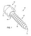
- FIG. 1is an isometric view of one example of an improved hammer toe implant
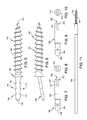
- FIG. 2is a top side view of the hammer toe implant illustrated in FIG. 1 ;
- FIG. 3is a sectional view of the hammer toe implant taken along line 3 - 3 in FIG. 2 ;
- FIG. 4is an end on view of the hammer toe implant taken along line 4 - 4 in FIG. 2 ;
- FIG. 5is a side view of another example of a hammer toe implant
- FIG. 6is a top side view of the hammer toe implant illustrated in FIG. 5 ;
- FIG. 7is a side view of one example of a driving adapter for use with the hammer toe implants illustrated in FIGS. 1 and 6 ;
- FIG. 8is an end view of the driving adapter illustrated in FIG. 7 ;
- FIG. 9is a side view of another example of a driving adapter for use with the hammer toe implants illustrated in FIGS. 1 and 6 ;
- FIG. 10is an end view of the driving adapter illustrated in FIG. 9 ;
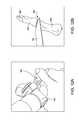
- FIG. 11is an assembly view of a hammer toe implant engaged by a driving adapter
- FIGS. 12A and 12Billustrate the middle and proximal phalanxes of a foot being resected
- FIG. 13illustrates a hammer toe implant being driven into a proximal phalanx
- FIG. 14illustrates a middle phalanx being drilled or broached
- FIG. 15illustrates a blade of a hammer toe implant extending from the proximal phalanx with the middle phalanx having been drilled or broached;
- FIG. 16illustrates a hammer toe implant installed in the middle and proximal phalanxes
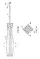
- FIG. 17illustrates another example of a driving assembly for installing an implant
- FIG. 18illustrates side view of the driving assembly illustrated in FIG. 17 ;
- FIG. 19is an isometric view of an adapter of the driving assembly illustrated in FIG. 17 ;
- FIG. 20is an end view of the adapter illustrated in FIG. 19 ;
- FIG. 21is a cross-sectional view of the adapter taken along line 21 - 21 in FIG. 20 ;
- FIG. 22is a cross-sectional view of the adapter taken along line 22 - 22 in FIG. 20 ;
- FIG. 23is a plan view of the driving rod of the driving assembly illustrated in FIG. 17 ;
- FIG. 24is a cross-sectional view of the driving rod taken along line 24 - 24 in FIG. 23 ;
- FIG. 25is a cross-sectional view of the fin of the driving rod taken along line 25 - 25 in FIG. 23 ;
- FIG. 26is a plan view of driving assembly illustrated in FIG. 17 without the o-ring;
- FIG. 27is a cross-sectional view of the handle taken along line 27 - 27 in FIG. 26 ;
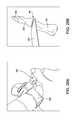
- FIGS. 28A and 28Billustrate the middle and proximal phalanxes of a foot being resected
- FIGS. 29A and 29Billustrate an implant coupled to the adapter of the driving assembly illustrated in FIG. 17 ;
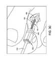
- FIG. 30illustrates a hammer toe implant being driven into a proximal phalanx
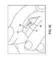
- FIG. 31illustrates a middle phalanx being drilled or broached
- FIG. 32illustrates a blade of a hammer toe implant extending from the proximal phalanx with the middle phalanx having been drilled or broached;
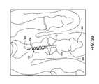
- FIG. 33illustrates a hammer toe implant installed in the middle and proximal phalanxes.
- FIG. 1illustrates one example of an improved implant 100 for treating hammer toe.
- implant 100includes a threaded portion 102 and a blade portion 104 , which are connected together at an engagement portion 106 .
- Implant 100may have a substantially linear geometry having an overall length of approximately 19 mm (approximately 0.75 inches).
- blade portion 104may be disposed at angle with respect to a longitudinal axis defined by the threaded portion 102 . The angle may be between zero and 45 degrees, and more particularly between approximately five and fifteen degrees, although one skilled in the art will understand that implant 100 may have other dimensions and be provided in different sizes.
- implant 100may be provided in lengths of 16 mm and 22 mm, to name a few potential lengths.
- Threaded portion 102may include a plurality of threads 108 disposed along its entire length, which may be approximately 13 mm (approximately 0.5 inches). The tip 110 of threaded portion 102 may be pointed to facilitate the advancement of threads 108 into bone. Threads 108 may have a maximum outer diameter of approximately 2 mm (approximately 0.08 inches), although one skilled in the art will understand that thread portion 102 may have other dimensions and be configured to be received within a phalanx bone of a person. For example, threads may have an outer diameter of approximately 2.4 mm and 1.6 mm, to name a few potential possibilities.
- blade portion 104includes a plurality of serrated edges 112 on its top and bottom sides 114 , 116 .
- Blade portion 104may have a width that is greater than its thickness as best seen in FIGS. 2 and 4 .
- blade portion 104may have a width of approximately 0.4 centimeters (approximately 0.16 inches) and a thickness of approximately 0.1 centimeters (approximately 0.04 inches) each of which taper to point 118 .
- Blade portion 104may have a substantially rectangular cross-sectional area as illustrated in FIG. 4 , although one skilled in the art will understand that blade portion 104 may have other cross-sectional geometries.
- Engagement portion 106may include a pair of protrusions 120 extending from opposite sides of implant 100 and having rounded outer edges 122 .
- the sides 124 of protrusions 120may be substantially parallel with each other as shown in FIG. 4 .
- Implant 100is configured to be installed using a driving adapter 200 such as the one illustrated in FIGS. 7-10 .
- the driving adapter 200has an elongate body 202 having a proximal end 204 and a distal end 206 .
- Body 202 of driving adapter 200may have a circular cross-sectional geometry, although one skilled in the art will understand that body 202 may have other cross-sectional geometries including, but not limited to, triangular, rectangular, pentagonal, and hexagonal to name a few.
- Proximal end 204may be substantially solid and have a rounded tip 208 .
- Distal end 206may define a slot 210 sized and configured to receive blade portion 104 of implant 100 therein.
- Slot 210may have a rectangular cross-sectional geometry and have a depth that is sufficient to receive the entire blade portion 104 of implant 100 such that distal edges 212 of slot 210 contact protrusions 120 of engagement portion 106 .
- slot 210may have other cross-sectional geometries and dimensions.
- Slot 210may extend through side walls 214 of body 202 as shown in FIGS. 7 and 8 , or side walls 214 may completely enclose slot 210 as shown in FIGS. 9 and 10 .
- slot 210may extend in a direction that is substantially parallel to an axis defined by body 202 of driving adapter 200 . If driving adapter 200 is to be used with an implant 100 having a blade portion 104 that extends at an angle with respect to an axis defined by elongate threaded portion 102 such as the implant illustrated in FIGS. 5 and 6 , then slot 210 may extend from distal edges 212 at an angle with respect to an axis defined by the length of body 202 such that elongate threaded portion 102 of implant 100 is linearly aligned with body 202 of driving adapter 200 as shown in FIG.
- slot 210 of driving adapter 200may extend at a ten degree angle with respect to a longitudinal axis defined by body 202 such that threaded portion 102 of implant 100 and body 202 of driving adapter 200 are substantially linearly aligned.
- a method of installing implant 100 in the proximal interphelangeal joint (PIP) 300is described with reference to FIGS. 12A-16 .
- the technique for installing the implant 100may be applied to other joints such as, for example, the distal interphelangeal (DIP) joint between middle phalanx 304 and distal phalanx 306 .
- DIPdistal interphelangeal
- FIGS. 12A and 12Ban incision is made to open the PIP joint 300 and a cutting tool 400 having a blade 402 may be used to resect adjacent faces of proximal phalanx 302 and middle phalanx 304 .
- the resected surfaces of proximal phalanx 302 and middle phalanx 304may be debrided as understood by one skilled in the art.
- Blade portion 104 of implant 100may be disposed within slot 210 of driving adapter 200 as shown in FIG. 11 , and the body 202 of driving adapter 200 may be secured in a chuck 412 of a drill 410 or other driving instrument as shown in FIG. 13 .
- Drill 410 or other driving instrumentis used to drive the threaded portion 102 of implant 100 into the resected surface of proximal phalanx 302 .
- driving adapter 200may be disengaged from blade portion 104 of implant 100 .
- Middle phalanx 304may be predrilled or broached using drill 410 to create a hole 308 as shown in FIGS. 14 and 15 .
- the predrilled or broached middle phalanx 304is then repositioned such that the predrilled hole or broach 308 aligns with the blade portion 104 of implant 100 .
- the middle phalanx 304is then pressed into engagement with the blade portion 104 as shown in FIG. 16 . Serrated edges 112 of blade portion 104 help to maintain the engagement between middle phalanx 304 and blade portion 104 of implant 100 .
- FIGS. 17-27illustrate another embodiment of a driver assembly 500 for installing an implant into bone.
- driver assembly 500includes an adapter 502 coupled to a driving rod 516 onto which a handle 534 is over-molded or otherwise coupled.
- Adapter 502includes a body 504 with a substantially rectangular side profile comprising side walls 506 - 1 , 506 - 2 , 506 - 3 , and 506 - 4 (collectively referred to as “side walls 506 ”) and a pair of end walls 508 - 1 , 508 - 2 (collectively referred to as “end walls 508 ”) having a substantially square geometry as best seen in FIGS. 19-22 .
- Body 504defines a recess 510 along the length of side walls 506 .
- Recess 510is dimensioned such that an o-ring 544 ( FIGS. 17 and 18 ) may be received therein. Additionally, recess 510 is located along side walls 506 at a distance from end walls 508 such that recess 510 is aligned with a valley 126 of serrated edges 112 along the top and bottom sides 114 , 116 of blade portion 104 .
- End wall 508 - 1defines an aperture 512 having a geometry that complements the cross-sectional geometry of blade portion 104 of implant 100 .
- aperture 512may extend approximately parallel to the lengthwise direction of side walls 506 . If the blade portion 104 of implant 100 is angled as illustrated in FIG. 6 , then aperture 512 may extend from wall 508 - 1 at an angle relative to the plane defined by side wall 506 - 2 or 506 - 4 as will be understood by one skilled in the art.
- aperture 512has a depth that is greater than or equal to a length of blade portion 104 such that blade portion 104 may be received within body 504 and engagement portion 106 abuts end wall 508 - 1 .
- end wall 508 - 2defines an aperture 514 that is sized and configured to receive an end of elongate driving rod 516 therein.
- driving rod 516includes a fin 518 disposed at a first end 520 .
- Fin 518 disposed at end 20 of driving rod 516has a rectangular shape and is sized and configured to be received within aperture 512 of adapter 502 .
- Fin 518defines a slot 522 , which is sized and configured to receive a pin (not shown) for cross-pinning driving rod 516 to adapter 502 .
- end 520may have other cross-sectional geometries including, but not limited to, triangular, square, and pentagonal, to name a few possibilities, that are configured to be received within aperture 512 .
- Adapter 502may be over-molded onto the end of driving rod 516 . However, one skilled in the art will understand that adapter 502 may be cross-pinned or otherwise coupled to driving rod 516 .
- the opposite end 524 of driving rod 516defines a pair of flats 526 , 528 , which are disposed on opposite sides of driving rod 516 .
- flat 526extends from tip 530 and is linearly spaced from flat 528 , which is disposed at a greater distance from tip 530 than flat 526 .
- flats 526 , 528may be disposed at other positions along driving rod 516 .
- Flats 526 , 528are configured to provide a contact surface for coupling to handle 532 , which may be over-molded onto driving rod 516 , such that rotation of handle 532 is translated to driving rod 516 .
- handle 532has an elongate body 534 that includes a plurality of ribs 536 that extend in a longitudinal direction along body 534 to provide a gripping surface for a user.
- a smooth surface 538interrupts circumferential ridges 540 , which are disposed adjacent to proximal end 542 also for providing a gripping surface for a user.
- Driver assembly 500may be provided in a kit with a first adapter 502 for use with a straight implant 100 and a second adapter for use with an angled implant 100 .
- a plurality of implants 100 of different sizesmay also be provided in the kit.
- the kitmay be used in an operation similar to the operation described above with respect to FIGS. 12A-16 .
- a cutting tool 400 having a blade 402may be used to resect adjacent faces of proximal phalanx 302 and middle phalanx 304 as illustrated in FIGS. 28A and 28B .
- the resected surfaces of proximal phalanx 302 and middle phalanx 304may be debrided as understood by one skilled in the art.
- Blade portion 104 of implant 100is disposed within aperture 512 of adapter 502 as shown in FIGS. 29A and 29B .
- an o-ring 544( FIGS. 17 and 18 ) is placed in recess 510 defined by adapter 502 and within a valley 126 of serrated edges 112 along the top and bottom sides 114 , 116 of blade portion 104 .
- O-ring 544secures implant 100 to adapter 502 such that implant does not move axially out of aperture 512 .
- Implant 100is secured to adapter 502 , the surgeon uses handle 534 to manually drive threaded portion 102 of implant 100 into the resected surface of proximal phalanx 302 as illustrated in FIG. 30 .
- Implant 100is driven into proximal phalanx 302 until engagement portion 106 abuts proximal phalanx 302 .
- Implant 100is decoupled from adapter 502 by axially pulling handle 534 away from implant 100 with sufficient force to flex o-ring 544 and separate adapter 502 from implant 100 .
- Middle phalanx 304may be predrilled or broached using drill 410 to create a hole 308 as shown in FIGS. 31 and 32 .
- the predrilled or broached middle phalanx 304is then repositioned such that the predrilled hole or broach 308 aligns with the blade portion 104 of implant 100 .
- the middle phalanx 304is then pressed into engagement with the blade portion 104 as shown in FIG. 33 . Serrated edges 112 of blade portion 104 help to maintain the engagement between middle phalanx 304 and blade portion 104 of implant 100 .
- the implant described abovemay advantageously be installed through a small incision as described above. Additionally, the improved implant is completely disposed within a toe of a patient, which prevents the implant from being caught on bed sheets or other objects like the conventional pins.
Landscapes
- Health & Medical Sciences (AREA)
- Orthopedic Medicine & Surgery (AREA)
- Surgery (AREA)
- Life Sciences & Earth Sciences (AREA)
- Heart & Thoracic Surgery (AREA)
- Nuclear Medicine, Radiotherapy & Molecular Imaging (AREA)
- Engineering & Computer Science (AREA)
- Biomedical Technology (AREA)
- Medical Informatics (AREA)
- Molecular Biology (AREA)
- Animal Behavior & Ethology (AREA)
- General Health & Medical Sciences (AREA)
- Public Health (AREA)
- Veterinary Medicine (AREA)
- Neurology (AREA)
- Prostheses (AREA)
Abstract
Description
Claims (22)
Priority Applications (8)
| Application Number | Priority Date | Filing Date | Title |
|---|---|---|---|
| US13/086,136US9072564B2 (en) | 2010-06-02 | 2011-04-13 | Hammer toe implant and method |
| US13/660,522US9044287B2 (en) | 2010-06-02 | 2012-10-25 | Hammer toe implant method |
| US13/660,495US20130060295A1 (en) | 2010-06-02 | 2012-10-25 | Hammer toe implant |
| US13/804,228US9498273B2 (en) | 2010-06-02 | 2013-03-14 | Orthopedic implant kit |
| US14/052,046US9724140B2 (en) | 2010-06-02 | 2013-10-11 | Tapered, cylindrical cruciform hammer toe implant and method |
| US14/067,096US20140052196A1 (en) | 2011-04-13 | 2013-10-30 | Hammer toe implant with living hinge and method |
| US15/299,862US9877753B2 (en) | 2010-06-02 | 2016-10-21 | Orthopedic implant kit |
| US15/878,889US10736676B2 (en) | 2010-06-02 | 2018-01-24 | Orthopedic implant kit |
Applications Claiming Priority (2)
| Application Number | Priority Date | Filing Date | Title |
|---|---|---|---|
| US35066510P | 2010-06-02 | 2010-06-02 | |
| US13/086,136US9072564B2 (en) | 2010-06-02 | 2011-04-13 | Hammer toe implant and method |
Related Parent Applications (1)
| Application Number | Title | Priority Date | Filing Date |
|---|---|---|---|
| US13/804,228Continuation-In-PartUS9498273B2 (en) | 2010-06-02 | 2013-03-14 | Orthopedic implant kit |
Related Child Applications (4)
| Application Number | Title | Priority Date | Filing Date |
|---|---|---|---|
| US13/660,522ContinuationUS9044287B2 (en) | 2010-06-02 | 2012-10-25 | Hammer toe implant method |
| US13/660,495ContinuationUS20130060295A1 (en) | 2010-06-02 | 2012-10-25 | Hammer toe implant |
| US13/804,228Continuation-In-PartUS9498273B2 (en) | 2010-06-02 | 2013-03-14 | Orthopedic implant kit |
| US14/067,096Continuation-In-PartUS20140052196A1 (en) | 2011-04-13 | 2013-10-30 | Hammer toe implant with living hinge and method |
Publications (2)
| Publication Number | Publication Date |
|---|---|
| US20110301652A1 US20110301652A1 (en) | 2011-12-08 |
| US9072564B2true US9072564B2 (en) | 2015-07-07 |
Family
ID=45065050
Family Applications (3)
| Application Number | Title | Priority Date | Filing Date |
|---|---|---|---|
| US13/086,136Active2031-04-21US9072564B2 (en) | 2010-06-02 | 2011-04-13 | Hammer toe implant and method |
| US13/660,522ActiveUS9044287B2 (en) | 2010-06-02 | 2012-10-25 | Hammer toe implant method |
| US13/660,495AbandonedUS20130060295A1 (en) | 2010-06-02 | 2012-10-25 | Hammer toe implant |
Family Applications After (2)
| Application Number | Title | Priority Date | Filing Date |
|---|---|---|---|
| US13/660,522ActiveUS9044287B2 (en) | 2010-06-02 | 2012-10-25 | Hammer toe implant method |
| US13/660,495AbandonedUS20130060295A1 (en) | 2010-06-02 | 2012-10-25 | Hammer toe implant |
Country Status (1)
| Country | Link |
|---|---|
| US (3) | US9072564B2 (en) |
Cited By (10)
| Publication number | Priority date | Publication date | Assignee | Title |
|---|---|---|---|---|
| US20170100172A1 (en)* | 2011-12-12 | 2017-04-13 | Wright Medical Technology, Inc. | Fusion implant |
| US10383671B2 (en) | 2008-09-09 | 2019-08-20 | Stryker European Holdings I, Llc | Resorptive intramedullary implant between two bones or two bone fragments |
| US20190301510A1 (en)* | 2018-04-03 | 2019-10-03 | Michael J. Mollo | Hanging Device |
| US10470807B2 (en) | 2016-06-03 | 2019-11-12 | Stryker European Holdings I, Llc | Intramedullary implant and method of use |
| USD874896S1 (en)* | 2018-06-19 | 2020-02-11 | Leatherman Tool Group, Inc. | Corkscrew |
| US10582957B2 (en) | 2014-09-19 | 2020-03-10 | Crossroads Extremity Systems, Llc | Bone fixation implant and means of fixation |
| US10660676B2 (en) | 2017-02-20 | 2020-05-26 | Paragon 28, Inc. | Implants, devices, instruments, systems and methods of forming and implanting |
| US10702318B2 (en) | 2015-03-03 | 2020-07-07 | Howmedica Osteonics Corp. | Orthopedic implant and methods of implanting and removing same |
| US11478285B2 (en) | 2005-04-14 | 2022-10-25 | Stryker European Operations Holdings Llc | Device for osteosyntheses or arthrodesis of two-bone parts, in particular of the hand and/or foot |
| US12207827B2 (en) | 2019-11-15 | 2025-01-28 | Paragon 28, Inc. | Instruments, systems, and methods of using |
Families Citing this family (52)
| Publication number | Priority date | Publication date | Assignee | Title |
|---|---|---|---|---|
| FR2913876B1 (en) | 2007-03-20 | 2009-06-05 | Memometal Technologies Soc Par | OSTEOSYNTHESIS DEVICE |
| US8377034B2 (en) | 2009-12-04 | 2013-02-19 | Std Med, Inc. | Vascular access port |
| US10349987B2 (en) | 2010-04-14 | 2019-07-16 | Arrowhead Medical Device Technologies, Llc | Intramedullary fixation devices |
| WO2014165123A1 (en) | 2013-03-13 | 2014-10-09 | Arrowhead Medical Device Technologies Llc | Hammertoe implant with enhanced gripping surfaces |
| US8685024B2 (en) | 2010-04-14 | 2014-04-01 | Arrowhead Medical Device Technologies, Llc | Intramedullary fixation device and methods for bone fixation and stabilization |
| US9724140B2 (en) | 2010-06-02 | 2017-08-08 | Wright Medical Technology, Inc. | Tapered, cylindrical cruciform hammer toe implant and method |
| US9498273B2 (en) | 2010-06-02 | 2016-11-22 | Wright Medical Technology, Inc. | Orthopedic implant kit |
| US8608785B2 (en) | 2010-06-02 | 2013-12-17 | Wright Medical Technology, Inc. | Hammer toe implant with expansion portion for retrograde approach |
| US9072564B2 (en) | 2010-06-02 | 2015-07-07 | Wright Medical Technology, Inc. | Hammer toe implant and method |
| US20130123862A1 (en)* | 2010-10-10 | 2013-05-16 | Gregory Anderson | Arthrodesis implant and buttressing apparatus and method |
| US20120089197A1 (en)* | 2010-10-10 | 2012-04-12 | Anderson Gregory S | Arthrodesis implant apparatus and method |
| US10111690B2 (en)* | 2010-10-10 | 2018-10-30 | Orthopro Llc | Arthrodesis implant and buttressing apparatus and method |
| US8998999B2 (en) | 2011-11-17 | 2015-04-07 | Orthohelix Surgical Designs, Inc. | Hammertoe implant |
| US9750553B1 (en)* | 2012-02-02 | 2017-09-05 | Ascension Orthopedics, Inc. | Interphalangeal fusion implant |
| WO2013177252A1 (en) | 2012-05-22 | 2013-11-28 | Lifenet Health | Cortical bone pin |
| US9775630B2 (en) | 2012-05-24 | 2017-10-03 | Orthopro Llc | Systems and methods for implanting surgical implants |
| US10058431B2 (en)* | 2012-10-19 | 2018-08-28 | Tyber Medical, LLC | Small joint fixation |
| US9056014B2 (en)* | 2012-12-27 | 2015-06-16 | Wright Medical Technology, Inc. | Device and method for fixation for bone or soft tissue deformity of digits |
| US8945232B2 (en) | 2012-12-31 | 2015-02-03 | Wright Medical Technology, Inc. | Ball and socket implants for correction of hammer toes and claw toes |
| US9974580B2 (en)* | 2013-03-13 | 2018-05-22 | Arrowhead Medical Device Technologies Llc | Hammertoe implant with asymmetrical head |
| WO2014159125A1 (en) | 2013-03-13 | 2014-10-02 | Arrowhead Medical Device Technologies Llc | Methods and implants for treating hammertoe and other deformities |
| US9517098B2 (en)* | 2013-07-03 | 2016-12-13 | Biomet Manufacturing, Llc | Bone fusion device |
| US9724139B2 (en)* | 2013-10-01 | 2017-08-08 | Wright Medical Technology, Inc. | Hammer toe implant and method |
| AU2014340051A1 (en) | 2013-10-23 | 2016-06-09 | Extremity Medical Llc | Devices and methods for bone fixation using an intramedullary fixation implant |
| US9474561B2 (en)* | 2013-11-19 | 2016-10-25 | Wright Medical Technology, Inc. | Two-wire technique for installing hammertoe implant |
| US9545274B2 (en)* | 2014-02-12 | 2017-01-17 | Wright Medical Technology, Inc. | Intramedullary implant, system, and method for inserting an implant into a bone |
| US9498266B2 (en) | 2014-02-12 | 2016-11-22 | Wright Medical Technology, Inc. | Intramedullary implant, system, and method for inserting an implant into a bone |
| AU2014203105B1 (en)* | 2014-03-28 | 2015-03-12 | Wright Medical Technology, Inc. | Hammer toe implant |
| US20170007416A1 (en)* | 2014-03-28 | 2017-01-12 | Wright Medical Technollogy, Inc. | Hammer toe implant |
| US10369345B2 (en) | 2014-03-31 | 2019-08-06 | Versago Vascular Access, Inc. | Medical access port, systems and methods of use thereof |
| WO2015153976A1 (en)* | 2014-04-03 | 2015-10-08 | Versago Vascular Access, Inc. | Devices and methods for installation and removal of a needle tip of a needle |
| US10716604B2 (en) | 2014-07-21 | 2020-07-21 | Maurho Medical, Inc. | Bone fusing device for fusing phalanges |
| AU2014331633B2 (en) | 2014-09-18 | 2017-06-22 | Wright Medical Technology, Inc | Hammertoe implant and instrument |
| US11154687B2 (en) | 2014-12-18 | 2021-10-26 | Versago Vascular Access, Inc. | Catheter patency systems and methods |
| CA2971434A1 (en) | 2014-12-18 | 2016-06-23 | Versago Vascular Access, Inc. | Devices, systems and methods for removal and replacement of a catheter for an implanted access port |
| CN105960211B (en) | 2014-12-19 | 2019-01-11 | 瑞特医疗技术公司 | Intramedullary Anchors for Interphalangeal Arthrodesis |
| USD773926S1 (en)* | 2015-06-01 | 2016-12-13 | Spinal Generations, Llc | Screw |
| EP3322460B1 (en) | 2015-07-14 | 2022-09-07 | Versago Vascular Access, Inc. | Medical access ports and transfer devices |
| US20170151061A1 (en)* | 2015-09-10 | 2017-06-01 | Vilex In Tennessee, Inc. | Arthrodesis Implant and System Therefor |
| USD846973S1 (en)* | 2015-09-17 | 2019-04-30 | Columbia Insurance Company | High-strength partition top anchor |
| US10407892B2 (en) | 2015-09-17 | 2019-09-10 | Columbia Insurance Company | High-strength partition top anchor and anchoring system utilizing the same |
| FR3048871A1 (en)* | 2016-03-16 | 2017-09-22 | Neosteo | MEDICAL IMPLANT AND ASSEMBLY COMPRISING SUCH A MEDICAL IMPLANT AND A PREHENDER OF SAID IMPLANT |
| US9949774B2 (en) | 2016-05-26 | 2018-04-24 | Timothy Chen | Axial compression implant |
| EP3727558A4 (en) | 2017-12-21 | 2022-01-19 | Versago Vascular Access, Inc. | MEDICAL ACCESS PORTS, TRANSFER DEVICES AND METHODS OF USE THEREOF |
| WO2019169319A1 (en)* | 2018-03-01 | 2019-09-06 | Paragon 28, Inc. | Implants and methods of use and assembly |
| US11246712B2 (en)* | 2018-03-01 | 2022-02-15 | Paragon 28, Inc. | Implants, systems, and methods of use and assembly |
| US10653432B2 (en) | 2018-08-10 | 2020-05-19 | Wright Medical Technology, Inc. | Osteotomy guide |
| JP7270063B2 (en)* | 2019-05-14 | 2023-05-09 | ローサイ・オーソペディックス・リミテッド | A set of tools for introducing implants |
| USD968608S1 (en) | 2019-08-12 | 2022-11-01 | Lifenet Health | Medical implant device |
| USD968609S1 (en) | 2019-09-12 | 2022-11-01 | Lifenet Health | Medical implant device |
| WO2021231329A1 (en) | 2020-05-11 | 2021-11-18 | Gensano Llc | Cannulated bone implant |
| US12310603B2 (en) | 2021-02-18 | 2025-05-27 | Treace Medical Concepts, Inc. | System and technique for metatarsal realignment with reduced incision length |
Citations (147)
| Publication number | Priority date | Publication date | Assignee | Title |
|---|---|---|---|---|
| US321389A (en)* | 1885-06-30 | Combined nail and screw | ||
| US346148A (en)* | 1886-07-27 | Daniel p | ||
| US348589A (en) | 1886-09-07 | sloan | ||
| US373074A (en) | 1887-11-15 | Wood-screw | ||
| US430236A (en) | 1890-06-17 | Island | ||
| US561968A (en) | 1896-06-16 | Georges cotjlon | ||
| US736121A (en)* | 1902-04-21 | 1903-08-11 | Abraham B Lipscomb | Boot-calk. |
| US821025A (en) | 1903-01-27 | 1906-05-22 | Joseph Bartlett Davies | Nail or screw for securing corrugated iron. |
| GB140983A (en) | 1919-10-27 | 1920-04-08 | Charles Louis Basham | Improvements in wood screws |
| FR736058A (en) | 1932-04-28 | 1932-11-18 | Improvements made to bolts to ensure the safety of assemblies | |
| US1966835A (en) | 1932-01-28 | 1934-07-17 | Dardelet Threadlock Corp | Fastening means |
| US2140749A (en) | 1936-08-05 | 1938-12-20 | Filshie Lead Head Nail Company | Capped nail |
| US2361107A (en) | 1944-03-08 | 1944-10-24 | Charles E Johnson | Self-locking valve tappet screw |
| US2451747A (en)* | 1945-03-23 | 1948-10-19 | Ernest T Kindt | Doweled structure |
| US2600517A (en) | 1948-09-29 | 1952-06-17 | Herschel L Rushing | Tell-tale screw spike |
| FR1036978A (en) | 1951-05-11 | 1953-09-14 | Karcher Schraubenwerke G M B H | Bolt |
| US2895368A (en) | 1955-01-21 | 1959-07-21 | Jr Paul R Trigg | Bolt having rolled grooves and recessed head to enhance uniform elongation |
| US3466669A (en)* | 1966-09-20 | 1969-09-16 | Univ Iowa | Intramedullary finger joint prosthesis |
| US3681786A (en) | 1970-07-13 | 1972-08-08 | Medical Eng Corp | Solid human prosthesis of varying consistency |
| US4156296A (en) | 1977-04-08 | 1979-05-29 | Bio-Dynamics, Inc. | Great (large) toe prosthesis and method of implanting |
| US4204284A (en) | 1977-11-16 | 1980-05-27 | Lord Corporation | Joint prosthesis with contoured pin |
| US4213208A (en) | 1977-12-05 | 1980-07-22 | Sheldon Marne | Metatarso-phalangeal joint implant |
| US4262665A (en) | 1979-06-27 | 1981-04-21 | Roalstad W L | Intramedullary compression device |
| US4275717A (en) | 1979-07-27 | 1981-06-30 | Zimmer Usa, Inc. | Intramedullary fixation device for fractured tubular bones |
| US4276660A (en) | 1979-05-25 | 1981-07-07 | Laure Prosthetics, Inc. | Carpometacarpal thumb joint |
| US4304011A (en) | 1980-08-25 | 1981-12-08 | Whelan Iii Edward J | Semi-constrained metacarpophalangeal prosthesis |
| US4367562A (en) | 1980-06-19 | 1983-01-11 | Georges Gauthier | Joint prosthesis |
| US4516569A (en) | 1982-05-06 | 1985-05-14 | National Research Development Corporation | Intramedullary orthopaedic devices |
| GB2119655B (en) | 1982-05-06 | 1985-05-15 | Nat Res Dev | Endoprosthesis] |
| US4590928A (en) | 1980-09-25 | 1986-05-27 | South African Invention Development Corporation | Surgical implant |
| US4642122A (en) | 1986-04-02 | 1987-02-10 | Laure Prosthetics, Inc. | Toe implant |
| US4655661A (en) | 1983-12-23 | 1987-04-07 | Richter-System Gmbh & Co. Kg | Self-cutting fast construction screw |
| US4731087A (en) | 1987-01-06 | 1988-03-15 | New York Society For The Relief Of The Ruptured And Crippled | Metatarsal-phalangeal prosthesis |
| FR2605878A1 (en) | 1986-10-30 | 1988-05-06 | Landos Applic Orthopediques Fs | Prosthesis for small joints, in particular metacarpophalangial and interphalangial joints |
| US4865606A (en)* | 1987-08-13 | 1989-09-12 | Friedrichsfeld Gmbh Keramik Und Kunststoffwerke | Endoprosthesis for a knee-joint |
| US4908031A (en) | 1989-07-27 | 1990-03-13 | Dow Corning Wright | Toe implant |
| US4932974A (en) | 1989-07-06 | 1990-06-12 | Pappas Michael J | Prosthetic device with predetermined crystal orientation |
| GB2227540A (en) | 1989-01-27 | 1990-08-01 | David Ian Quarmby | Self-countersinking screws |
| US4955916A (en) | 1989-05-01 | 1990-09-11 | Techmedica, Inc. | Thumb joint prosthesis |
| US4963144A (en) | 1989-03-17 | 1990-10-16 | Huene Donald R | Bone screw fixation assembly, bone screw therefor and method of fixation |
| FR2651119A1 (en) | 1989-08-23 | 1991-03-01 | Felman Daniel | Phalangeal articular prosthesis |
| US5007932A (en) | 1985-01-08 | 1991-04-16 | Ngk Spark Plug Co., Ltd. | Artificial bone joint |
| US5037440A (en) | 1989-06-06 | 1991-08-06 | Koenig Implant, Inc. | Orthopedic toe implant |
| US5047059A (en) | 1987-09-28 | 1991-09-10 | Philippe Saffar | Prosthesis for metacarpopealangeal or interphalangeal articulation of the fingers |
| US5092896A (en) | 1989-09-28 | 1992-03-03 | Protek Ag | Finger joint prosthesis |
| US5133761A (en) | 1991-06-12 | 1992-07-28 | Research Development Foundation | Finger joint prosthesis |
| US5147363A (en)* | 1989-12-21 | 1992-09-15 | Haerle Anton | Screw for use in osteosynthesis |
| US5179915A (en) | 1992-01-06 | 1993-01-19 | Osteonics Corporation | Anatomically matching intramedullary alignment rod |
| EP0340159B1 (en) | 1988-04-27 | 1993-01-20 | GebràDer Sulzer Aktiengesellschaft | Dowel pin for cementless bone implants |
| FR2645735B1 (en) | 1989-04-14 | 1993-02-05 | Diebold Patrice | PROSTHESIS OF METATARSO-PHALANGIAN JOINT OF THE FIRST RAY OF THE FOOT |
| US5199839A (en) | 1991-10-09 | 1993-04-06 | Abbott-Interfast Corporation | Fastener screw having improved installation and self-locking characteristics |
| US5207712A (en) | 1992-05-07 | 1993-05-04 | Michael Cohen | Absorbable joint implants for the lesser digits and metatarsal phalangeal joints in the surgical correction of the foot |
| US5326366A (en) | 1993-02-16 | 1994-07-05 | Wright Medical Technology, Inc. | Biomechanical great toe implant |
| US5330476A (en) | 1991-11-18 | 1994-07-19 | Christophe Obry | Protective cap for an osteosynthesis pin and assembly including this cap as well as an instrument for fixing it on the pin |
| EP0409364B1 (en) | 1989-07-13 | 1994-09-28 | ARTOS Medizinische Produkte GmbH | Junction element for osteosynthesis |
| US5354301A (en) | 1993-03-19 | 1994-10-11 | Castellano Bradley D | Hammer toe operation tool system and method |
| US5417692A (en) | 1994-01-04 | 1995-05-23 | Goble; E. Marlowe | Bone fixation and fusion system |
| US5425776A (en) | 1992-05-07 | 1995-06-20 | Cohen; Michael | Method of using absorbable joint implants for the lesser digits and metatarsal phalangeal joints in the surgical correction of the foot |
| US5425777A (en) | 1992-12-23 | 1995-06-20 | Sarkisian; James S. | Artificial finger joint |
| US5458648A (en) | 1994-02-24 | 1995-10-17 | Kinetikos Medical, Inc. | Great toe joint implant and method of implantation |
| US5480447A (en) | 1992-12-15 | 1996-01-02 | International Polymer Engineering, Inc. | Joint implant |
| US5484443A (en) | 1992-01-03 | 1996-01-16 | Wright Medical Technology, Inc. | Instrument for inserting a protective sleeve into the medullary canal of a bone |
| US5498265A (en) | 1991-03-05 | 1996-03-12 | Howmedica Inc. | Screw and driver |
| US5516248A (en) | 1994-09-07 | 1996-05-14 | Abbott-Interfast Corporation | Low torque wood screw |
| US5522903A (en) | 1993-11-10 | 1996-06-04 | Jbs S.A. | Finger prosthesis |
| US5529075A (en) | 1994-09-12 | 1996-06-25 | Clark; David | Fixation device and method for repair of pronounced hallux valgus |
| US5595563A (en) | 1995-09-05 | 1997-01-21 | Moisdon; Roger G. F. | Method and apparatus for maintaining the position of body parts |
| US5601558A (en) | 1993-02-17 | 1997-02-11 | Smith & Nephew Endoscopy, Inc. | Soft tissue anchors and systems for implantation |
| US5634925A (en) | 1993-02-19 | 1997-06-03 | Alphatec Manufacturing, Inc. | Apparatus and method for spinal fixation system |
| US5669913A (en) | 1995-12-22 | 1997-09-23 | Zobel; Robert A. | Method and apparatus for smoothing an anatomical joint bearing surface during hemi-joint replacement |
| US5674297A (en) | 1995-12-08 | 1997-10-07 | Lane; Lewis B. | Metacarpophalangeal prosthesis |
| US5683466A (en) | 1996-03-26 | 1997-11-04 | Vitale; Glenn C. | Joint surface replacement system |
| US5713904A (en) | 1997-02-12 | 1998-02-03 | Third Millennium Engineering, Llc | Selectively expandable sacral fixation screw-sleeve device |
| US5725585A (en) | 1997-02-27 | 1998-03-10 | Zobel; Robert A. | Anatomically correct great toe implant and surgical procedure for implanting the same |
| US5776202A (en) | 1993-09-07 | 1998-07-07 | Copf; Franz | Joint prosthesis |
| US5919193A (en) | 1996-03-14 | 1999-07-06 | Slavitt; Jerome A. | Method and kit for surgically correcting malformations in digits of a finger or toe |
| US5928236A (en)* | 1994-07-04 | 1999-07-27 | Depuy France | Locking pin or screw device for an osteosynthesis plate or for the coaptation of bone fragments |
| US5951288A (en) | 1998-07-03 | 1999-09-14 | Sawa; Shlaimon T. | Self expanding dental implant and method for using the same |
| GB2336415A (en) | 1998-04-14 | 1999-10-20 | Kenneth Williams | Self countersinking screw |
| US5984971A (en) | 1995-02-17 | 1999-11-16 | Tecres S.P.A. | Prosthesis for metacarpal-phalangeal and interphalangeal joints in hands or feet |
| US6030162A (en) | 1998-12-18 | 2000-02-29 | Acumed, Inc. | Axial tension screw |
| US6048343A (en) | 1999-06-02 | 2000-04-11 | Mathis; John M. | Bone screw system |
| US6099571A (en) | 1997-07-16 | 2000-08-08 | Knapp; John G. | Joint prosthesis |
| US6102642A (en)* | 1997-02-20 | 2000-08-15 | Yamahiro Co., Ltd. | Screw head |
| FR2783702B1 (en) | 1998-09-29 | 2001-01-19 | Maurice Bertholet | SELF-LOCKING DEVICE FOR PROSTHESES |
| US6200345B1 (en) | 1997-01-18 | 2001-03-13 | Diro, Inc. | Locking taper attachment system having improved bacterial seal |
| FR2787313B1 (en) | 1998-12-17 | 2001-05-04 | Orsco Internat | OSTEOSYNTHESIS IMPLANT |
| US6248109B1 (en) | 1998-07-30 | 2001-06-19 | Waldemar Link (Gmbh & Co.) | Implant for interconnecting two bone fragments |
| FR2794019B1 (en) | 1999-05-26 | 2001-08-24 | Orsco Internat | OSTEOSYNTHESIS IMPLANT |
| US20010028836A1 (en)* | 2000-04-11 | 2001-10-11 | Jk Kabushiki Kaisha | Pull stud bolt |
| US6319284B1 (en) | 2000-05-31 | 2001-11-20 | Futura Biomedical Llc | Toe implant |
| US6352560B1 (en) | 1998-07-03 | 2002-03-05 | Van Straten Beheer B.V. | Joint prosthesis |
| US6383223B1 (en) | 1997-06-18 | 2002-05-07 | BAEHLER ANDRé | Endoprosthesis for a joint, especially a finger, toe or wrist joint |
| US6386877B1 (en) | 1998-07-30 | 2002-05-14 | Franz Sutter | Implant for holding and/or forming a dental prosthesis or artificial finger joint |
| US20020072803A1 (en) | 2000-11-29 | 2002-06-13 | Saunders Gerald Anthony Briden | Metatarsophalangeal resurfacing joint |
| US6413260B1 (en) | 1999-08-17 | 2002-07-02 | Pioneer Laboratories, Inc. | Bone connector system |
| US6423097B2 (en) | 2000-03-21 | 2002-07-23 | Sulzer Orthopedics Ltd. | Artificial finger joint |
| US20020111690A1 (en) | 2001-01-16 | 2002-08-15 | Hyde Edward R. | Joint prosthesis and method of implantation |
| US6454808B1 (en) | 1998-01-28 | 2002-09-24 | M-E-System Inc. | Finger joint prosthesis |
| US6458134B1 (en) | 1999-08-17 | 2002-10-01 | Pioneer Laboratories, Inc. | Bone connector system with anti-rotational feature |
| US6517543B1 (en) | 1999-08-17 | 2003-02-11 | Pioneer Laboratories, Inc. | Bone connector system with anti-rotational feature |
| US6551343B1 (en) | 1998-04-01 | 2003-04-22 | Bionx Implants, Oy | Bioabsorbable surgical fastener for tissue treatment |
| US20030191422A1 (en) | 2002-04-03 | 2003-10-09 | Sossong Charles E. | Claw toe straightening clamp |
| US6679668B2 (en)* | 2000-12-07 | 2004-01-20 | Bell South Intellectual Property Corporation | Double-ended fastener |
| US20040097941A1 (en) | 2002-11-20 | 2004-05-20 | Millennium Medical Technologies Inc. | Compression bone fragment wire |
| US20040220574A1 (en)* | 2001-07-16 | 2004-11-04 | Pelo Mark Joseph | Device from naturally occuring biologically derived materials |
| US20040230313A1 (en) | 2001-11-29 | 2004-11-18 | Saunders Gerald A.B. | Metatarsophalangeal resurfacing joint |
| US20050123672A1 (en) | 2003-12-03 | 2005-06-09 | Justin Daniel F. | Laser based metal deposition of implant structures |
| US20050187636A1 (en) | 2004-02-19 | 2005-08-25 | Graham Michael E. | Sinus tarsi implant |
| FR2846545B1 (en) | 2002-10-30 | 2005-09-09 | Bouali Amara | INTRAMEDULAR OSTEOSYNTHESIS IMPLANT |
| US20050283159A1 (en) | 2004-06-17 | 2005-12-22 | Bouali Amara | Intramedullary osteosynthesis implant |
| US20060074492A1 (en) | 2004-09-09 | 2006-04-06 | Theo Frey | Endoprosthesis for a metatarsophalangeal joint |
| US7041106B1 (en)* | 2001-06-15 | 2006-05-09 | Biomet, Inc. | Interphalangeal fusion pin |
| US20060100715A1 (en) | 2002-09-19 | 2006-05-11 | De Villiers Malan | Arthroplasty implant |
| US20060129153A1 (en) | 2003-04-10 | 2006-06-15 | Kaj Klaue | Device for temporarily splinting toes |
| WO2006109004A1 (en) | 2005-04-14 | 2006-10-19 | Memometal Technologies | Intramedullar osteosynthetic device of two bone parts, in particular of the hand and/or foot |
| US7192445B2 (en) | 2000-12-06 | 2007-03-20 | Astra Tech Ab | Medical prosthetic devices and implants having improved biocompatibility |
| GB2430625A (en) | 2005-09-30 | 2007-04-04 | Andrew Malcolm Jackson | Joint fusion peg |
| US20070078518A1 (en) | 2005-08-22 | 2007-04-05 | Vilex, Inc. | Cannulated hemi-implant and methods of use thereof |
| US7207994B2 (en) | 2002-02-12 | 2007-04-24 | Pioneer Laboratories, Inc. | Cannulated bone screw |
| US20070142920A1 (en) | 2005-12-20 | 2007-06-21 | Niemi Willard J | Metatarsal implant |
| US20070177959A1 (en)* | 2006-01-27 | 2007-08-02 | Panduit Corp. | Data center cabinet bonding stud |
| US20070213831A1 (en) | 2004-07-09 | 2007-09-13 | De Cubber Jan | Finger or toe prosthesis |
| US7291175B1 (en) | 2005-01-06 | 2007-11-06 | David J Gordon | Metatarsal phalangeal implant with locking screw |
| US20080051912A1 (en) | 2004-11-08 | 2008-02-28 | Small Bone Innovations, Inc. | Metatarsal implant |
| US20080086139A1 (en) | 2006-10-04 | 2008-04-10 | Gerard Bourke | Toe deformity repair using bioabsorbable pin |
| US20080195215A1 (en) | 2007-02-09 | 2008-08-14 | Morton Troy N | Artificial toe joint |
| US20080221697A1 (en) | 2007-03-06 | 2008-09-11 | Robert Graser | Hemi-implant for first metatarsophalangeal joint |
| US20100061825A1 (en)* | 2008-09-05 | 2010-03-11 | Lisong Liu | Two-way nails, two-way screws and their mounting tools |
| US20100131072A1 (en) | 2008-11-25 | 2010-05-27 | Schulte Robert C | Intra-osseus fusion system |
| US20100185295A1 (en) | 2006-06-23 | 2010-07-22 | Implants International Limited | Articulation prosthesis for small bones, in particular for phalangeal, metacarpo-phalangeal or metatarso-phalangeal articulations |
| US20100249942A1 (en) | 2009-03-27 | 2010-09-30 | Wright State University | Toe joint replacement models |
| US20100262254A1 (en) | 2009-04-09 | 2010-10-14 | Solana Surgical LLC | Metatarsal bone implant |
| US7837738B2 (en) | 2005-02-16 | 2010-11-23 | Swemac Orthopaedics Ab | Joint prosthesis and use of screw tool for positioning members thereof |
| US20110004255A1 (en) | 2009-02-19 | 2011-01-06 | Nextremity Solutions, Llc | Bone joining apparatus and method |
| US7909880B1 (en) | 2007-06-04 | 2011-03-22 | Grant William P | Toe cap implant |
| US20110082508A1 (en) | 2009-10-02 | 2011-04-07 | Jason M. Hiatt | Apparatus and Method for Use in the Treatment of Hammertoe |
| US20110082507A1 (en) | 2005-05-13 | 2011-04-07 | Kaj Klaue | Osteosynthesis Device |
| US20110093085A1 (en) | 2007-02-09 | 2011-04-21 | Morton Troy N | Artificial joint and insert |
| US20110144644A1 (en)* | 2008-09-09 | 2011-06-16 | Memometal Technologies | Resorptive intramedullary implant between two bones or two bone fragments |
| US20110257652A1 (en) | 2010-04-14 | 2011-10-20 | Arrowhead Medical Device Technologies, LLC. | Intramedullary fixation device and methods for bone fixation and stabilization |
| US20110301653A1 (en) | 2010-06-02 | 2011-12-08 | Wright Medical Technology, Inc. | Hammer toe implant with expansion portion for retrograde approach |
| US20110301652A1 (en) | 2010-06-02 | 2011-12-08 | Wright Medical Technology, Inc. | Hammer toe implant and method |
| US20120065692A1 (en) | 2010-09-10 | 2012-03-15 | Lloyd Champagne | Proximal interphalangeal fusion device |
| US8262712B2 (en) | 2006-11-16 | 2012-09-11 | New Deal | Phalangeal arthrodesis implant, surgical kit and method for manufacturing same |
| US8616091B2 (en)* | 2008-02-06 | 2013-12-31 | Process Displays | Peg board display fastener and connector |
| US8636457B2 (en)* | 2009-06-25 | 2014-01-28 | Robert W. Connors | Two-way fastener |
Family Cites Families (66)
| Publication number | Priority date | Publication date | Assignee | Title |
|---|---|---|---|---|
| US882937A (en)* | 1908-03-24 | North Bros M F G Co | Screw-eye driver. | |
| US2697370A (en)* | 1951-09-04 | 1954-12-21 | Linzy W Brooks | Ratchet type socket wrench |
| US2832245A (en)* | 1956-02-15 | 1958-04-29 | Burrows Allen | Sponge-rubber liner for socket wrench |
| DE3016932C2 (en)* | 1980-05-02 | 1985-11-28 | Hermann Werner Gmbh & Co, 5600 Wuppertal | Screwdriver with an exchangeable blade with a multi-edged shaft cross-section |
| RO89820B1 (en) | 1985-11-05 | 2002-06-28 | îNTREPRINDEREA INDUSTRIA TEHNICO MEDICALA | Elastic implants for a stable elastic osteorrhaphy of femoral and tibial fractures, respectively, as well as corresponding instrumentation |
| FR2622100B1 (en) | 1987-10-27 | 1991-02-15 | Barouk Louis | JOINT PROSTHETIC IMPLANT WITH TEMPORARY FIXING |
| SE466732B (en) | 1987-10-29 | 1992-03-30 | Atos Medical Ab | LED PROTES, INCLUDING A LED BODY BETWEEN ONE COUPLE OF TAPS FOR INSTALLATION |
| SE466936B (en) | 1989-04-25 | 1992-05-04 | Branemark Per Ingvar | ANCHORING ELEMENT FOR PROCESSING |
| FR2668361A1 (en) | 1990-10-30 | 1992-04-30 | Mai Christian | OSTEOSYNTHESIS CLIP AND PLATE WITH SELF-RETENTIVE DYNAMIC COMPRESSION. |
| US5171252A (en) | 1991-02-05 | 1992-12-15 | Friedland Thomas W | Surgical fastening clip formed of a shape memory alloy, a method of making such a clip and a method of using such a clip |
| US5213347A (en)* | 1991-04-29 | 1993-05-25 | Lisle Corporation | Socket driveable tap apparatus |
| JPH0671467B2 (en) | 1991-06-05 | 1994-09-14 | 有限会社大元産業 | Tooth fixing member |
| IT1257628B (en) | 1992-01-14 | 1996-02-01 | ENDOMIDOLLAR NAIL FOR DYNAMIC OSTEOSYNTHESIS WITH A DISTAL SELF-LOCKING END FOR FRACTURES OF THE FEMORAL TROCANTERIC REGION | |
| IT228979Y1 (en) | 1992-03-09 | 1998-06-05 | Giannini Sandro | BIODEGRADABLE PROSTHESIS FOR READY FOOT CORRECTION. |
| FR2695026B1 (en) | 1992-08-25 | 1994-10-28 | Alexandre Worcel | Device for maintaining compression of a fractured bone. |
| FR2697743B1 (en) | 1992-11-09 | 1995-01-27 | Fabrication Mat Orthopedique S | Spinal osteosynthesis device applicable in particular to degenerative vertebrae. |
| FR2700464B1 (en) | 1992-11-13 | 1995-04-14 | Maurice Bertholet | Connecting piece for bone elements. |
| US6197065B1 (en) | 1993-11-01 | 2001-03-06 | Biomet, Inc. | Method and apparatus for segmental bone replacement |
| US5470230A (en) | 1994-09-30 | 1995-11-28 | Daftary; Fereidoun | Anatomical dental implant with expandable root |
| GB2299941A (en) | 1995-04-20 | 1996-10-23 | Halifax Orthopaedic Research L | Securing means for an intramedullary rod |
| GR1003032B (en) | 1996-07-10 | 1998-12-16 | Intramedullary, flexible fracture fixation device, using bi-axial pre-stressing. | |
| US6984241B2 (en) | 1996-09-13 | 2006-01-10 | Tendon Technology, Ltd. | Apparatus and methods for tendon or ligament repair |
| FR2754702B1 (en) | 1996-10-18 | 1999-01-08 | Medinov Amp | DEVICE FOR SOLIDARIZING AT LEAST TWO VERTEBRAL BODIES |
| US6632224B2 (en) | 1996-11-12 | 2003-10-14 | Triage Medical, Inc. | Bone fixation system |
| US5707395A (en) | 1997-01-16 | 1998-01-13 | Li Medical Technologies, Inc. | Surgical fastener and method and apparatus for ligament repair |
| US6332885B1 (en) | 1998-05-07 | 2001-12-25 | Pasquale Martella | Synthesis device for orthopaedia and traumatology |
| US6200321B1 (en) | 1998-09-10 | 2001-03-13 | Hand Innovations, Inc. | Fracture fixation system |
| US6045573A (en) | 1999-01-21 | 2000-04-04 | Ethicon, Inc. | Suture anchor having multiple sutures |
| US6875235B2 (en) | 1999-10-08 | 2005-04-05 | Bret A. Ferree | Prosthetic joints with contained compressible resilient members |
| US6575976B2 (en) | 2000-06-12 | 2003-06-10 | Arthrex, Inc. | Expandable tissue anchor |
| CA2390912C (en) | 2001-07-05 | 2008-01-29 | Depuy France | Self-tapping screw for small-bone surgery |
| US6533788B1 (en) | 2001-11-01 | 2003-03-18 | Hand Innovations, Inc. | Locking device for intramedullary pin fixation |
| CA2476731C (en) | 2002-02-25 | 2007-07-03 | Jeffrey E. Yeung | Expandable fastener with compressive grips |
| US7695471B2 (en) | 2003-04-18 | 2010-04-13 | The University Of Hong Kong | Fixation device |
| US7670362B2 (en) | 2003-06-13 | 2010-03-02 | Tyco Healthcare Group Lp | Multiple member interconnect for surgical instrument and absorbable screw fastener |
| WO2005016174A2 (en) | 2003-06-27 | 2005-02-24 | Advanced Bio Surfaces, Inc. | Method and system for toe arthroplasty |
| FR2861577B1 (en) | 2003-11-05 | 2006-02-10 | Ceravic | IMPLANTABLE ORTHESIS AND SURGICAL KIT FOR ARTHRODESIS OF THE KNEE |
| US7766920B2 (en) | 2003-11-26 | 2010-08-03 | Synthes Usa, Llc | Cannulated fastener system |
| FR2863867B1 (en) | 2003-12-22 | 2007-05-04 | Memometal Technologies | INTERPHALANGIAN AND / OR METACARPOPHALANGIAN PROSTHESIS |
| US8162942B2 (en) | 2004-03-31 | 2012-04-24 | Orthofix S.R.L. | Intramedullary nail comprising elements of shape-memory material |
| US7585316B2 (en) | 2004-05-21 | 2009-09-08 | Warsaw Orthopedic, Inc. | Interspinous spacer |
| SE528323C2 (en) | 2004-06-01 | 2006-10-17 | Medvelop Ab | Joint prosthesis |
| US7887589B2 (en) | 2004-11-23 | 2011-02-15 | Glenn Bradley J | Minimally invasive spinal disc stabilizer and insertion tool |
| US20060200151A1 (en) | 2005-01-28 | 2006-09-07 | Dustin Ducharme | Orthopedic screw for use in repairing small bones |
| US8197509B2 (en) | 2005-06-29 | 2012-06-12 | Depuy Mitek, Inc. | Suture anchor with improved torsional drive head |
| US7727235B2 (en) | 2005-06-29 | 2010-06-01 | Ethicon, Inc. | Medical fixation devices with improved torsional drive head |
| US8118849B2 (en) | 2006-03-17 | 2012-02-21 | Tornier, Inc. | Bone screw with selectively securable washer |
| FR2901119B1 (en) | 2006-05-19 | 2008-12-12 | Memometal Technologies Soc Par | DEVICE FOR SUPPORTING A SURGICAL IMPLANT WITH SHAPE MEMORY |
| FR2908035B1 (en) | 2006-11-08 | 2009-05-01 | Jean Taylor | INTEREPINE IMPLANT |
| DE102006056950B4 (en) | 2006-11-30 | 2013-07-25 | Normed Medizin-Technik Gmbh | Orthopedic lag screw for osteosynthesis and / or fixation of bone segments |
| US8317845B2 (en) | 2007-01-19 | 2012-11-27 | Alexa Medical, Llc | Screw and method of use |
| FR2913876B1 (en) | 2007-03-20 | 2009-06-05 | Memometal Technologies Soc Par | OSTEOSYNTHESIS DEVICE |
| US8043334B2 (en) | 2007-04-13 | 2011-10-25 | Depuy Spine, Inc. | Articulating facet fusion screw |
| US8696716B2 (en) | 2007-08-02 | 2014-04-15 | Proactive Orthopedics, Llc | Fixation and alignment device and method used in orthopaedic surgery |
| US8394132B2 (en) | 2008-09-16 | 2013-03-12 | Orthohelix Surgical Designs, Inc. | Orthopedic compression screw |
| US9468465B2 (en) | 2009-02-19 | 2016-10-18 | Nextremity Solutions, Inc. | Reversible bone coupling device and method |
| US8529608B2 (en) | 2009-04-28 | 2013-09-10 | Osteomed Llc | Bone plate with a transfixation screw hole |
| US20130079776A1 (en) | 2009-08-25 | 2013-03-28 | Paul Zwirkoski | Bone compression system |
| US8535355B2 (en) | 2009-10-15 | 2013-09-17 | Biomet C.V. | Dorsal midfoot bone plate system and method |
| FR2957244B1 (en) | 2010-03-09 | 2012-04-13 | Synchro Medical | ARTHRODESE IMPLANT |
| US20120016428A1 (en) | 2010-06-28 | 2012-01-19 | Mtp Solutions, Llc | Bunion correction method and device |
| US20120089197A1 (en) | 2010-10-10 | 2012-04-12 | Anderson Gregory S | Arthrodesis implant apparatus and method |
| US10111690B2 (en) | 2010-10-10 | 2018-10-30 | Orthopro Llc | Arthrodesis implant and buttressing apparatus and method |
| US20120259419A1 (en) | 2011-04-05 | 2012-10-11 | Michael Glyn Brown | Method and apparatus for the treatment of metatarsophalangeal joint degenerative arthritis |
| US8998999B2 (en) | 2011-11-17 | 2015-04-07 | Orthohelix Surgical Designs, Inc. | Hammertoe implant |
| US20130150965A1 (en) | 2011-12-12 | 2013-06-13 | Alan G. Taylor | Fusion implant |
- 2011
- 2011-04-13USUS13/086,136patent/US9072564B2/enactiveActive
- 2012
- 2012-10-25USUS13/660,522patent/US9044287B2/enactiveActive
- 2012-10-25USUS13/660,495patent/US20130060295A1/ennot_activeAbandoned
Patent Citations (148)
| Publication number | Priority date | Publication date | Assignee | Title |
|---|---|---|---|---|
| US321389A (en)* | 1885-06-30 | Combined nail and screw | ||
| US346148A (en)* | 1886-07-27 | Daniel p | ||
| US348589A (en) | 1886-09-07 | sloan | ||
| US373074A (en) | 1887-11-15 | Wood-screw | ||
| US430236A (en) | 1890-06-17 | Island | ||
| US561968A (en) | 1896-06-16 | Georges cotjlon | ||
| US736121A (en)* | 1902-04-21 | 1903-08-11 | Abraham B Lipscomb | Boot-calk. |
| US821025A (en) | 1903-01-27 | 1906-05-22 | Joseph Bartlett Davies | Nail or screw for securing corrugated iron. |
| GB140983A (en) | 1919-10-27 | 1920-04-08 | Charles Louis Basham | Improvements in wood screws |
| US1966835A (en) | 1932-01-28 | 1934-07-17 | Dardelet Threadlock Corp | Fastening means |
| FR736058A (en) | 1932-04-28 | 1932-11-18 | Improvements made to bolts to ensure the safety of assemblies | |
| US2140749A (en) | 1936-08-05 | 1938-12-20 | Filshie Lead Head Nail Company | Capped nail |
| US2361107A (en) | 1944-03-08 | 1944-10-24 | Charles E Johnson | Self-locking valve tappet screw |
| US2451747A (en)* | 1945-03-23 | 1948-10-19 | Ernest T Kindt | Doweled structure |
| US2600517A (en) | 1948-09-29 | 1952-06-17 | Herschel L Rushing | Tell-tale screw spike |
| FR1036978A (en) | 1951-05-11 | 1953-09-14 | Karcher Schraubenwerke G M B H | Bolt |
| US2895368A (en) | 1955-01-21 | 1959-07-21 | Jr Paul R Trigg | Bolt having rolled grooves and recessed head to enhance uniform elongation |
| US3466669A (en)* | 1966-09-20 | 1969-09-16 | Univ Iowa | Intramedullary finger joint prosthesis |
| US3681786A (en) | 1970-07-13 | 1972-08-08 | Medical Eng Corp | Solid human prosthesis of varying consistency |
| US4156296A (en) | 1977-04-08 | 1979-05-29 | Bio-Dynamics, Inc. | Great (large) toe prosthesis and method of implanting |
| US4204284A (en) | 1977-11-16 | 1980-05-27 | Lord Corporation | Joint prosthesis with contoured pin |
| US4213208A (en) | 1977-12-05 | 1980-07-22 | Sheldon Marne | Metatarso-phalangeal joint implant |
| US4276660A (en) | 1979-05-25 | 1981-07-07 | Laure Prosthetics, Inc. | Carpometacarpal thumb joint |
| US4262665A (en) | 1979-06-27 | 1981-04-21 | Roalstad W L | Intramedullary compression device |
| US4275717A (en) | 1979-07-27 | 1981-06-30 | Zimmer Usa, Inc. | Intramedullary fixation device for fractured tubular bones |
| US4367562A (en) | 1980-06-19 | 1983-01-11 | Georges Gauthier | Joint prosthesis |
| US4304011A (en) | 1980-08-25 | 1981-12-08 | Whelan Iii Edward J | Semi-constrained metacarpophalangeal prosthesis |
| US4590928A (en) | 1980-09-25 | 1986-05-27 | South African Invention Development Corporation | Surgical implant |
| US4516569A (en) | 1982-05-06 | 1985-05-14 | National Research Development Corporation | Intramedullary orthopaedic devices |
| GB2119655B (en) | 1982-05-06 | 1985-05-15 | Nat Res Dev | Endoprosthesis] |
| US4655661A (en) | 1983-12-23 | 1987-04-07 | Richter-System Gmbh & Co. Kg | Self-cutting fast construction screw |
| US5007932A (en) | 1985-01-08 | 1991-04-16 | Ngk Spark Plug Co., Ltd. | Artificial bone joint |
| US4642122A (en) | 1986-04-02 | 1987-02-10 | Laure Prosthetics, Inc. | Toe implant |
| FR2605878A1 (en) | 1986-10-30 | 1988-05-06 | Landos Applic Orthopediques Fs | Prosthesis for small joints, in particular metacarpophalangial and interphalangial joints |
| US4731087A (en) | 1987-01-06 | 1988-03-15 | New York Society For The Relief Of The Ruptured And Crippled | Metatarsal-phalangeal prosthesis |
| US4865606A (en)* | 1987-08-13 | 1989-09-12 | Friedrichsfeld Gmbh Keramik Und Kunststoffwerke | Endoprosthesis for a knee-joint |
| US5047059A (en) | 1987-09-28 | 1991-09-10 | Philippe Saffar | Prosthesis for metacarpopealangeal or interphalangeal articulation of the fingers |
| EP0340159B1 (en) | 1988-04-27 | 1993-01-20 | GebràDer Sulzer Aktiengesellschaft | Dowel pin for cementless bone implants |
| GB2227540A (en) | 1989-01-27 | 1990-08-01 | David Ian Quarmby | Self-countersinking screws |
| US4963144A (en) | 1989-03-17 | 1990-10-16 | Huene Donald R | Bone screw fixation assembly, bone screw therefor and method of fixation |
| FR2645735B1 (en) | 1989-04-14 | 1993-02-05 | Diebold Patrice | PROSTHESIS OF METATARSO-PHALANGIAN JOINT OF THE FIRST RAY OF THE FOOT |
| US4955916A (en) | 1989-05-01 | 1990-09-11 | Techmedica, Inc. | Thumb joint prosthesis |
| US5037440A (en) | 1989-06-06 | 1991-08-06 | Koenig Implant, Inc. | Orthopedic toe implant |
| US4932974A (en) | 1989-07-06 | 1990-06-12 | Pappas Michael J | Prosthetic device with predetermined crystal orientation |
| EP0409364B1 (en) | 1989-07-13 | 1994-09-28 | ARTOS Medizinische Produkte GmbH | Junction element for osteosynthesis |
| US4908031A (en) | 1989-07-27 | 1990-03-13 | Dow Corning Wright | Toe implant |
| FR2651119A1 (en) | 1989-08-23 | 1991-03-01 | Felman Daniel | Phalangeal articular prosthesis |
| US5092896A (en) | 1989-09-28 | 1992-03-03 | Protek Ag | Finger joint prosthesis |
| US5147363A (en)* | 1989-12-21 | 1992-09-15 | Haerle Anton | Screw for use in osteosynthesis |
| US5498265A (en) | 1991-03-05 | 1996-03-12 | Howmedica Inc. | Screw and driver |
| US5133761A (en) | 1991-06-12 | 1992-07-28 | Research Development Foundation | Finger joint prosthesis |
| US5199839A (en) | 1991-10-09 | 1993-04-06 | Abbott-Interfast Corporation | Fastener screw having improved installation and self-locking characteristics |
| US5330476A (en) | 1991-11-18 | 1994-07-19 | Christophe Obry | Protective cap for an osteosynthesis pin and assembly including this cap as well as an instrument for fixing it on the pin |
| US5484443A (en) | 1992-01-03 | 1996-01-16 | Wright Medical Technology, Inc. | Instrument for inserting a protective sleeve into the medullary canal of a bone |
| US5179915A (en) | 1992-01-06 | 1993-01-19 | Osteonics Corporation | Anatomically matching intramedullary alignment rod |
| US5207712A (en) | 1992-05-07 | 1993-05-04 | Michael Cohen | Absorbable joint implants for the lesser digits and metatarsal phalangeal joints in the surgical correction of the foot |
| US5425776A (en) | 1992-05-07 | 1995-06-20 | Cohen; Michael | Method of using absorbable joint implants for the lesser digits and metatarsal phalangeal joints in the surgical correction of the foot |
| US5480447A (en) | 1992-12-15 | 1996-01-02 | International Polymer Engineering, Inc. | Joint implant |
| US5425777A (en) | 1992-12-23 | 1995-06-20 | Sarkisian; James S. | Artificial finger joint |
| US5326366A (en) | 1993-02-16 | 1994-07-05 | Wright Medical Technology, Inc. | Biomechanical great toe implant |
| US5601558A (en) | 1993-02-17 | 1997-02-11 | Smith & Nephew Endoscopy, Inc. | Soft tissue anchors and systems for implantation |
| EP0611557B1 (en) | 1993-02-17 | 1999-04-21 | Smith & Nephew, Inc. | Surgical implant & surgical kit |
| US5634925A (en) | 1993-02-19 | 1997-06-03 | Alphatec Manufacturing, Inc. | Apparatus and method for spinal fixation system |
| US5354301A (en) | 1993-03-19 | 1994-10-11 | Castellano Bradley D | Hammer toe operation tool system and method |
| US5776202A (en) | 1993-09-07 | 1998-07-07 | Copf; Franz | Joint prosthesis |
| US5522903A (en) | 1993-11-10 | 1996-06-04 | Jbs S.A. | Finger prosthesis |
| US5417692A (en) | 1994-01-04 | 1995-05-23 | Goble; E. Marlowe | Bone fixation and fusion system |
| US5458648A (en) | 1994-02-24 | 1995-10-17 | Kinetikos Medical, Inc. | Great toe joint implant and method of implantation |
| US5928236A (en)* | 1994-07-04 | 1999-07-27 | Depuy France | Locking pin or screw device for an osteosynthesis plate or for the coaptation of bone fragments |
| US5516248A (en) | 1994-09-07 | 1996-05-14 | Abbott-Interfast Corporation | Low torque wood screw |
| US5529075A (en) | 1994-09-12 | 1996-06-25 | Clark; David | Fixation device and method for repair of pronounced hallux valgus |
| US5984971A (en) | 1995-02-17 | 1999-11-16 | Tecres S.P.A. | Prosthesis for metacarpal-phalangeal and interphalangeal joints in hands or feet |
| US5595563A (en) | 1995-09-05 | 1997-01-21 | Moisdon; Roger G. F. | Method and apparatus for maintaining the position of body parts |
| US5674297A (en) | 1995-12-08 | 1997-10-07 | Lane; Lewis B. | Metacarpophalangeal prosthesis |
| US5669913A (en) | 1995-12-22 | 1997-09-23 | Zobel; Robert A. | Method and apparatus for smoothing an anatomical joint bearing surface during hemi-joint replacement |
| US5919193A (en) | 1996-03-14 | 1999-07-06 | Slavitt; Jerome A. | Method and kit for surgically correcting malformations in digits of a finger or toe |
| US5683466A (en) | 1996-03-26 | 1997-11-04 | Vitale; Glenn C. | Joint surface replacement system |
| US6200345B1 (en) | 1997-01-18 | 2001-03-13 | Diro, Inc. | Locking taper attachment system having improved bacterial seal |
| US5713904A (en) | 1997-02-12 | 1998-02-03 | Third Millennium Engineering, Llc | Selectively expandable sacral fixation screw-sleeve device |
| US6102642A (en)* | 1997-02-20 | 2000-08-15 | Yamahiro Co., Ltd. | Screw head |
| US5725585A (en) | 1997-02-27 | 1998-03-10 | Zobel; Robert A. | Anatomically correct great toe implant and surgical procedure for implanting the same |
| US6383223B1 (en) | 1997-06-18 | 2002-05-07 | BAEHLER ANDRé | Endoprosthesis for a joint, especially a finger, toe or wrist joint |
| US6099571A (en) | 1997-07-16 | 2000-08-08 | Knapp; John G. | Joint prosthesis |
| US6454808B1 (en) | 1998-01-28 | 2002-09-24 | M-E-System Inc. | Finger joint prosthesis |
| US6551343B1 (en) | 1998-04-01 | 2003-04-22 | Bionx Implants, Oy | Bioabsorbable surgical fastener for tissue treatment |
| GB2336415A (en) | 1998-04-14 | 1999-10-20 | Kenneth Williams | Self countersinking screw |
| US6352560B1 (en) | 1998-07-03 | 2002-03-05 | Van Straten Beheer B.V. | Joint prosthesis |
| US5951288A (en) | 1998-07-03 | 1999-09-14 | Sawa; Shlaimon T. | Self expanding dental implant and method for using the same |
| US6386877B1 (en) | 1998-07-30 | 2002-05-14 | Franz Sutter | Implant for holding and/or forming a dental prosthesis or artificial finger joint |
| US6248109B1 (en) | 1998-07-30 | 2001-06-19 | Waldemar Link (Gmbh & Co.) | Implant for interconnecting two bone fragments |
| FR2783702B1 (en) | 1998-09-29 | 2001-01-19 | Maurice Bertholet | SELF-LOCKING DEVICE FOR PROSTHESES |
| FR2787313B1 (en) | 1998-12-17 | 2001-05-04 | Orsco Internat | OSTEOSYNTHESIS IMPLANT |
| US6030162A (en) | 1998-12-18 | 2000-02-29 | Acumed, Inc. | Axial tension screw |
| FR2794019B1 (en) | 1999-05-26 | 2001-08-24 | Orsco Internat | OSTEOSYNTHESIS IMPLANT |
| US6048343A (en) | 1999-06-02 | 2000-04-11 | Mathis; John M. | Bone screw system |
| US6458134B1 (en) | 1999-08-17 | 2002-10-01 | Pioneer Laboratories, Inc. | Bone connector system with anti-rotational feature |
| US6413260B1 (en) | 1999-08-17 | 2002-07-02 | Pioneer Laboratories, Inc. | Bone connector system |
| US6517543B1 (en) | 1999-08-17 | 2003-02-11 | Pioneer Laboratories, Inc. | Bone connector system with anti-rotational feature |
| US6423097B2 (en) | 2000-03-21 | 2002-07-23 | Sulzer Orthopedics Ltd. | Artificial finger joint |
| US20010028836A1 (en)* | 2000-04-11 | 2001-10-11 | Jk Kabushiki Kaisha | Pull stud bolt |
| US6319284B1 (en) | 2000-05-31 | 2001-11-20 | Futura Biomedical Llc | Toe implant |
| US20020072803A1 (en) | 2000-11-29 | 2002-06-13 | Saunders Gerald Anthony Briden | Metatarsophalangeal resurfacing joint |
| US7192445B2 (en) | 2000-12-06 | 2007-03-20 | Astra Tech Ab | Medical prosthetic devices and implants having improved biocompatibility |
| US6679668B2 (en)* | 2000-12-07 | 2004-01-20 | Bell South Intellectual Property Corporation | Double-ended fastener |
| US20020111690A1 (en) | 2001-01-16 | 2002-08-15 | Hyde Edward R. | Joint prosthesis and method of implantation |
| US7041106B1 (en)* | 2001-06-15 | 2006-05-09 | Biomet, Inc. | Interphalangeal fusion pin |
| US20040220574A1 (en)* | 2001-07-16 | 2004-11-04 | Pelo Mark Joseph | Device from naturally occuring biologically derived materials |
| US20040230313A1 (en) | 2001-11-29 | 2004-11-18 | Saunders Gerald A.B. | Metatarsophalangeal resurfacing joint |
| US7207994B2 (en) | 2002-02-12 | 2007-04-24 | Pioneer Laboratories, Inc. | Cannulated bone screw |
| US20030191422A1 (en) | 2002-04-03 | 2003-10-09 | Sossong Charles E. | Claw toe straightening clamp |
| US20060100715A1 (en) | 2002-09-19 | 2006-05-11 | De Villiers Malan | Arthroplasty implant |
| FR2846545B1 (en) | 2002-10-30 | 2005-09-09 | Bouali Amara | INTRAMEDULAR OSTEOSYNTHESIS IMPLANT |
| US20040097941A1 (en) | 2002-11-20 | 2004-05-20 | Millennium Medical Technologies Inc. | Compression bone fragment wire |
| US20060129153A1 (en) | 2003-04-10 | 2006-06-15 | Kaj Klaue | Device for temporarily splinting toes |
| US20050123672A1 (en) | 2003-12-03 | 2005-06-09 | Justin Daniel F. | Laser based metal deposition of implant structures |
| US20050187636A1 (en) | 2004-02-19 | 2005-08-25 | Graham Michael E. | Sinus tarsi implant |
| US20050283159A1 (en) | 2004-06-17 | 2005-12-22 | Bouali Amara | Intramedullary osteosynthesis implant |
| US20070213831A1 (en) | 2004-07-09 | 2007-09-13 | De Cubber Jan | Finger or toe prosthesis |
| US20060074492A1 (en) | 2004-09-09 | 2006-04-06 | Theo Frey | Endoprosthesis for a metatarsophalangeal joint |
| US20080051912A1 (en) | 2004-11-08 | 2008-02-28 | Small Bone Innovations, Inc. | Metatarsal implant |
| US7291175B1 (en) | 2005-01-06 | 2007-11-06 | David J Gordon | Metatarsal phalangeal implant with locking screw |
| US7837738B2 (en) | 2005-02-16 | 2010-11-23 | Swemac Orthopaedics Ab | Joint prosthesis and use of screw tool for positioning members thereof |
| WO2006109004A1 (en) | 2005-04-14 | 2006-10-19 | Memometal Technologies | Intramedullar osteosynthetic device of two bone parts, in particular of the hand and/or foot |
| US20110082507A1 (en) | 2005-05-13 | 2011-04-07 | Kaj Klaue | Osteosynthesis Device |
| US20070078518A1 (en) | 2005-08-22 | 2007-04-05 | Vilex, Inc. | Cannulated hemi-implant and methods of use thereof |
| GB2430625A (en) | 2005-09-30 | 2007-04-04 | Andrew Malcolm Jackson | Joint fusion peg |
| US20070142920A1 (en) | 2005-12-20 | 2007-06-21 | Niemi Willard J | Metatarsal implant |
| US20070177959A1 (en)* | 2006-01-27 | 2007-08-02 | Panduit Corp. | Data center cabinet bonding stud |
| US20100185295A1 (en) | 2006-06-23 | 2010-07-22 | Implants International Limited | Articulation prosthesis for small bones, in particular for phalangeal, metacarpo-phalangeal or metatarso-phalangeal articulations |
| US20080086139A1 (en) | 2006-10-04 | 2008-04-10 | Gerard Bourke | Toe deformity repair using bioabsorbable pin |
| US8262712B2 (en) | 2006-11-16 | 2012-09-11 | New Deal | Phalangeal arthrodesis implant, surgical kit and method for manufacturing same |
| US20080195215A1 (en) | 2007-02-09 | 2008-08-14 | Morton Troy N | Artificial toe joint |
| US20110093085A1 (en) | 2007-02-09 | 2011-04-21 | Morton Troy N | Artificial joint and insert |
| US20080221697A1 (en) | 2007-03-06 | 2008-09-11 | Robert Graser | Hemi-implant for first metatarsophalangeal joint |
| US7909880B1 (en) | 2007-06-04 | 2011-03-22 | Grant William P | Toe cap implant |
| US8616091B2 (en)* | 2008-02-06 | 2013-12-31 | Process Displays | Peg board display fastener and connector |
| US20100061825A1 (en)* | 2008-09-05 | 2010-03-11 | Lisong Liu | Two-way nails, two-way screws and their mounting tools |
| US20110144644A1 (en)* | 2008-09-09 | 2011-06-16 | Memometal Technologies | Resorptive intramedullary implant between two bones or two bone fragments |
| US20100131072A1 (en) | 2008-11-25 | 2010-05-27 | Schulte Robert C | Intra-osseus fusion system |
| US20110004255A1 (en) | 2009-02-19 | 2011-01-06 | Nextremity Solutions, Llc | Bone joining apparatus and method |
| US20100249942A1 (en) | 2009-03-27 | 2010-09-30 | Wright State University | Toe joint replacement models |
| US20100262254A1 (en) | 2009-04-09 | 2010-10-14 | Solana Surgical LLC | Metatarsal bone implant |
| US8636457B2 (en)* | 2009-06-25 | 2014-01-28 | Robert W. Connors | Two-way fastener |
| US20110082508A1 (en) | 2009-10-02 | 2011-04-07 | Jason M. Hiatt | Apparatus and Method for Use in the Treatment of Hammertoe |
| US20110257652A1 (en) | 2010-04-14 | 2011-10-20 | Arrowhead Medical Device Technologies, LLC. | Intramedullary fixation device and methods for bone fixation and stabilization |
| US20110301653A1 (en) | 2010-06-02 | 2011-12-08 | Wright Medical Technology, Inc. | Hammer toe implant with expansion portion for retrograde approach |
| US20110301652A1 (en) | 2010-06-02 | 2011-12-08 | Wright Medical Technology, Inc. | Hammer toe implant and method |
| US20120065692A1 (en) | 2010-09-10 | 2012-03-15 | Lloyd Champagne | Proximal interphalangeal fusion device |
Cited By (18)
| Publication number | Priority date | Publication date | Assignee | Title |
|---|---|---|---|---|
| US11478285B2 (en) | 2005-04-14 | 2022-10-25 | Stryker European Operations Holdings Llc | Device for osteosyntheses or arthrodesis of two-bone parts, in particular of the hand and/or foot |
| US10383671B2 (en) | 2008-09-09 | 2019-08-20 | Stryker European Holdings I, Llc | Resorptive intramedullary implant between two bones or two bone fragments |
| US12390255B2 (en) | 2008-09-09 | 2025-08-19 | Stryker European Operations Holdings Llc | Resorptive intramedullary implant between two bones or two bone fragments |
| US12383319B2 (en) | 2008-09-09 | 2025-08-12 | Stryker European Operations Holdings Llc | Resorptive intramedullary implant between two bones or two bone fragments |
| US12059186B2 (en) | 2008-09-09 | 2024-08-13 | Stryker European Operations Holdings Llc | Resorptive intramedullary implant between two bones or two bone fragments |
| US10463407B2 (en)* | 2011-12-12 | 2019-11-05 | Wright Medical Technology, Inc. | Fusion implant |
| US20170100172A1 (en)* | 2011-12-12 | 2017-04-13 | Wright Medical Technology, Inc. | Fusion implant |
| US10582957B2 (en) | 2014-09-19 | 2020-03-10 | Crossroads Extremity Systems, Llc | Bone fixation implant and means of fixation |
| US11672576B2 (en) | 2015-03-03 | 2023-06-13 | Howmedica Osteonics Corp. | Orthopedic implant and methods of implanting and removing same |
| US12383318B2 (en) | 2015-03-03 | 2025-08-12 | Howmedica Osteonics Corp. | Orthopedic implant and methods of implanting and removing same |
| US10702318B2 (en) | 2015-03-03 | 2020-07-07 | Howmedica Osteonics Corp. | Orthopedic implant and methods of implanting and removing same |
| US10470807B2 (en) | 2016-06-03 | 2019-11-12 | Stryker European Holdings I, Llc | Intramedullary implant and method of use |
| US11992248B2 (en) | 2016-06-03 | 2024-05-28 | Stryker European Operations Holdings Llc | Intramedullary implant and method of use |
| US11272966B2 (en) | 2016-06-03 | 2022-03-15 | Stryker European Operations Holdings Llc | Intramedullary implant and method of use |
| US10660676B2 (en) | 2017-02-20 | 2020-05-26 | Paragon 28, Inc. | Implants, devices, instruments, systems and methods of forming and implanting |
| US20190301510A1 (en)* | 2018-04-03 | 2019-10-03 | Michael J. Mollo | Hanging Device |
| USD874896S1 (en)* | 2018-06-19 | 2020-02-11 | Leatherman Tool Group, Inc. | Corkscrew |
| US12207827B2 (en) | 2019-11-15 | 2025-01-28 | Paragon 28, Inc. | Instruments, systems, and methods of using |
Also Published As
| Publication number | Publication date |
|---|---|
| US9044287B2 (en) | 2015-06-02 |
| US20110301652A1 (en) | 2011-12-08 |
| US20130053975A1 (en) | 2013-02-28 |
| US20130060295A1 (en) | 2013-03-07 |
Similar Documents
| Publication | Publication Date | Title |
|---|---|---|
| US9072564B2 (en) | Hammer toe implant and method | |
| US20140052196A1 (en) | Hammer toe implant with living hinge and method | |
| CA2864697C (en) | Hammer toe implant and method | |
| US9675392B2 (en) | Two-wire technique for installing hammertoe implant | |
| US9724140B2 (en) | Tapered, cylindrical cruciform hammer toe implant and method | |
| US10736676B2 (en) | Orthopedic implant kit | |
| US10786291B2 (en) | Proximal bunion resection guides and plates and methods of use | |
| US9615873B2 (en) | Bone joining apparatus and method | |
| US20170156877A1 (en) | Hammer toe implant with expansion portion for retrograde approach | |
| AU2017200430B2 (en) | Tapered, cylindrical cruciform hammer toe implant and method |
Legal Events
| Date | Code | Title | Description |
|---|---|---|---|
| AS | Assignment | Owner name:WRIGHT MEDICAL TECHNOLOGY, INC., TENNESSEE Free format text:ASSIGNMENT OF ASSIGNORS INTEREST;ASSIGNORS:REED, WESLEY;KOKA, DINESH V.;SIGNING DATES FROM 20110412 TO 20110413;REEL/FRAME:026142/0610 | |
| STCF | Information on status: patent grant | Free format text:PATENTED CASE | |
| AS | Assignment | Owner name:MIDCAP FINANCIAL TRUST, AS AGENT, MARYLAND Free format text:SECURITY INTEREST;ASSIGNOR:WRIGHT MEDICAL TECHNOLOGY, INC.;REEL/FRAME:041257/0126 Effective date:20161223 | |
| MAFP | Maintenance fee payment | Free format text:PAYMENT OF MAINTENANCE FEE, 4TH YEAR, LARGE ENTITY (ORIGINAL EVENT CODE: M1551); ENTITY STATUS OF PATENT OWNER: LARGE ENTITY Year of fee payment:4 | |
| AS | Assignment | Owner name:BIOMIMETIC THERAPEUTICS, LLC, TENNESSEE Free format text:RELEASE BY SECURED PARTY;ASSIGNOR:MIDCAP FUNDING IV TRUST;REEL/FRAME:054480/0001 Effective date:20201112 Owner name:WHITE BOX ORTHOPEDICS, LLC, TENNESSEE Free format text:RELEASE BY SECURED PARTY;ASSIGNOR:MIDCAP FUNDING IV TRUST;REEL/FRAME:054480/0001 Effective date:20201112 Owner name:TORNIER, INC., MINNESOTA Free format text:RELEASE BY SECURED PARTY;ASSIGNOR:MIDCAP FUNDING IV TRUST;REEL/FRAME:054480/0001 Effective date:20201112 Owner name:INBONE TECHNOLOGIES, INC., TENNESSEE Free format text:RELEASE BY SECURED PARTY;ASSIGNOR:MIDCAP FUNDING IV TRUST;REEL/FRAME:054480/0001 Effective date:20201112 Owner name:SOLANA SURGICAL, LLC, TENNESSEE Free format text:RELEASE BY SECURED PARTY;ASSIGNOR:MIDCAP FUNDING IV TRUST;REEL/FRAME:054480/0001 Effective date:20201112 Owner name:BIOMIMETIC THERAPEUTICS USA, INC., TENNESSEE Free format text:RELEASE BY SECURED PARTY;ASSIGNOR:MIDCAP FUNDING IV TRUST;REEL/FRAME:054480/0001 Effective date:20201112 Owner name:TROOPER HOLDINGS INC., MINNESOTA Free format text:RELEASE BY SECURED PARTY;ASSIGNOR:MIDCAP FUNDING IV TRUST;REEL/FRAME:054480/0001 Effective date:20201112 Owner name:WRIGHT MEDICAL GROUP N.V., NETHERLANDS Free format text:RELEASE BY SECURED PARTY;ASSIGNOR:MIDCAP FUNDING IV TRUST;REEL/FRAME:054480/0001 Effective date:20201112 Owner name:WRIGHT MEDICAL GROUP, INC., TENNESSEE Free format text:RELEASE BY SECURED PARTY;ASSIGNOR:MIDCAP FUNDING IV TRUST;REEL/FRAME:054480/0001 Effective date:20201112 Owner name:ORTHOPRO, L.L.C., TENNESSEE Free format text:RELEASE BY SECURED PARTY;ASSIGNOR:MIDCAP FUNDING IV TRUST;REEL/FRAME:054480/0001 Effective date:20201112 Owner name:ORTHOHELIX SURGICAL DESIGNS, INC., MINNESOTA Free format text:RELEASE BY SECURED PARTY;ASSIGNOR:MIDCAP FUNDING IV TRUST;REEL/FRAME:054480/0001 Effective date:20201112 Owner name:WRIGHT MEDICAL CAPITAL, INC., TENNESSEE Free format text:RELEASE BY SECURED PARTY;ASSIGNOR:MIDCAP FUNDING IV TRUST;REEL/FRAME:054480/0001 Effective date:20201112 Owner name:WRIGHT MEDICAL GROUP INTELLECTUAL PROPERTY, INC., TENNESSEE Free format text:RELEASE BY SECURED PARTY;ASSIGNOR:MIDCAP FUNDING IV TRUST;REEL/FRAME:054480/0001 Effective date:20201112 Owner name:WRIGHT MEDICAL TECHNOLOGY, INC., TENNESSEE Free format text:RELEASE BY SECURED PARTY;ASSIGNOR:MIDCAP FUNDING IV TRUST;REEL/FRAME:054480/0001 Effective date:20201112 Owner name:BIOMIMETIC THERAPEUTICS CANADA, INC., TENNESSEE Free format text:RELEASE BY SECURED PARTY;ASSIGNOR:MIDCAP FUNDING IV TRUST;REEL/FRAME:054480/0001 Effective date:20201112 Owner name:TORNIER US HOLDINGS, INC., MINNESOTA Free format text:RELEASE BY SECURED PARTY;ASSIGNOR:MIDCAP FUNDING IV TRUST;REEL/FRAME:054480/0001 Effective date:20201112 | |
| MAFP | Maintenance fee payment | Free format text:PAYMENT OF MAINTENANCE FEE, 8TH YEAR, LARGE ENTITY (ORIGINAL EVENT CODE: M1552); ENTITY STATUS OF PATENT OWNER: LARGE ENTITY Year of fee payment:8 |