US9072552B2 - Intramedullary nail and implant system comprising the nail - Google Patents
Intramedullary nail and implant system comprising the nailDownload PDFInfo
- Publication number
- US9072552B2 US9072552B2US13/763,858US201313763858AUS9072552B2US 9072552 B2US9072552 B2US 9072552B2US 201313763858 AUS201313763858 AUS 201313763858AUS 9072552 B2US9072552 B2US 9072552B2
- Authority
- US
- United States
- Prior art keywords
- bore
- intramedullary nail
- axis
- transverse bore
- proximal portion
- Prior art date
- Legal status (The legal status is an assumption and is not a legal conclusion. Google has not performed a legal analysis and makes no representation as to the accuracy of the status listed.)
- Active, expires
Links
Images


Classifications
- A—HUMAN NECESSITIES
- A61—MEDICAL OR VETERINARY SCIENCE; HYGIENE
- A61B—DIAGNOSIS; SURGERY; IDENTIFICATION
- A61B17/00—Surgical instruments, devices or methods
- A61B17/56—Surgical instruments or methods for treatment of bones or joints; Devices specially adapted therefor
- A61B17/58—Surgical instruments or methods for treatment of bones or joints; Devices specially adapted therefor for osteosynthesis, e.g. bone plates, screws or setting implements
- A61B17/68—Internal fixation devices, including fasteners and spinal fixators, even if a part thereof projects from the skin
- A61B17/72—Intramedullary devices, e.g. pins or nails
- A61B17/7233—Intramedullary devices, e.g. pins or nails with special means of locking the nail to the bone
- A—HUMAN NECESSITIES
- A61—MEDICAL OR VETERINARY SCIENCE; HYGIENE
- A61B—DIAGNOSIS; SURGERY; IDENTIFICATION
- A61B17/00—Surgical instruments, devices or methods
- A61B17/56—Surgical instruments or methods for treatment of bones or joints; Devices specially adapted therefor
- A61B17/58—Surgical instruments or methods for treatment of bones or joints; Devices specially adapted therefor for osteosynthesis, e.g. bone plates, screws or setting implements
- A61B17/68—Internal fixation devices, including fasteners and spinal fixators, even if a part thereof projects from the skin
- A61B17/74—Devices for the head or neck or trochanter of the femur
- A61B17/742—Devices for the head or neck or trochanter of the femur having one or more longitudinal elements oriented along or parallel to the axis of the neck
- A—HUMAN NECESSITIES
- A61—MEDICAL OR VETERINARY SCIENCE; HYGIENE
- A61B—DIAGNOSIS; SURGERY; IDENTIFICATION
- A61B17/00—Surgical instruments, devices or methods
- A61B17/56—Surgical instruments or methods for treatment of bones or joints; Devices specially adapted therefor
- A61B17/58—Surgical instruments or methods for treatment of bones or joints; Devices specially adapted therefor for osteosynthesis, e.g. bone plates, screws or setting implements
- A61B17/68—Internal fixation devices, including fasteners and spinal fixators, even if a part thereof projects from the skin
- A61B17/72—Intramedullary devices, e.g. pins or nails
- A61B17/7233—Intramedullary devices, e.g. pins or nails with special means of locking the nail to the bone
- A61B17/7241—Intramedullary devices, e.g. pins or nails with special means of locking the nail to the bone the nail having separate elements through which screws pass
- A—HUMAN NECESSITIES
- A61—MEDICAL OR VETERINARY SCIENCE; HYGIENE
- A61B—DIAGNOSIS; SURGERY; IDENTIFICATION
- A61B17/00—Surgical instruments, devices or methods
- A61B17/56—Surgical instruments or methods for treatment of bones or joints; Devices specially adapted therefor
- A61B17/58—Surgical instruments or methods for treatment of bones or joints; Devices specially adapted therefor for osteosynthesis, e.g. bone plates, screws or setting implements
- A61B17/68—Internal fixation devices, including fasteners and spinal fixators, even if a part thereof projects from the skin
- A61B17/74—Devices for the head or neck or trochanter of the femur
- A61B17/742—Devices for the head or neck or trochanter of the femur having one or more longitudinal elements oriented along or parallel to the axis of the neck
- A61B17/744—Devices for the head or neck or trochanter of the femur having one or more longitudinal elements oriented along or parallel to the axis of the neck the longitudinal elements coupled to an intramedullary nail
- A—HUMAN NECESSITIES
- A61—MEDICAL OR VETERINARY SCIENCE; HYGIENE
- A61B—DIAGNOSIS; SURGERY; IDENTIFICATION
- A61B17/00—Surgical instruments, devices or methods
- A61B17/56—Surgical instruments or methods for treatment of bones or joints; Devices specially adapted therefor
- A61B17/58—Surgical instruments or methods for treatment of bones or joints; Devices specially adapted therefor for osteosynthesis, e.g. bone plates, screws or setting implements
- A61B17/88—Osteosynthesis instruments; Methods or means for implanting or extracting internal or external fixation devices
- B—PERFORMING OPERATIONS; TRANSPORTING
- B23—MACHINE TOOLS; METAL-WORKING NOT OTHERWISE PROVIDED FOR
- B23C—MILLING
- B23C3/00—Milling particular work; Special milling operations; Machines therefor
- B23C3/28—Grooving workpieces
- A—HUMAN NECESSITIES
- A61—MEDICAL OR VETERINARY SCIENCE; HYGIENE
- A61B—DIAGNOSIS; SURGERY; IDENTIFICATION
- A61B17/00—Surgical instruments, devices or methods
- A61B2017/00526—Methods of manufacturing
- A—HUMAN NECESSITIES
- A61—MEDICAL OR VETERINARY SCIENCE; HYGIENE
- A61B—DIAGNOSIS; SURGERY; IDENTIFICATION
- A61B17/00—Surgical instruments, devices or methods
- A61B17/56—Surgical instruments or methods for treatment of bones or joints; Devices specially adapted therefor
- A61B2017/564—Methods for bone or joint treatment
- Y—GENERAL TAGGING OF NEW TECHNOLOGICAL DEVELOPMENTS; GENERAL TAGGING OF CROSS-SECTIONAL TECHNOLOGIES SPANNING OVER SEVERAL SECTIONS OF THE IPC; TECHNICAL SUBJECTS COVERED BY FORMER USPC CROSS-REFERENCE ART COLLECTIONS [XRACs] AND DIGESTS
- Y10—TECHNICAL SUBJECTS COVERED BY FORMER USPC
- Y10T—TECHNICAL SUBJECTS COVERED BY FORMER US CLASSIFICATION
- Y10T409/00—Gear cutting, milling, or planing
- Y10T409/30—Milling
- Y10T409/303752—Process
- Y10T409/303808—Process including infeeding
Definitions
- the present disclosuregenerally relates to an intramedullary nail for internal fixation of a bone, such as a femur.
- the disclosurefurther relates to an implant system for use in orthopaedic surgery and to a method of manufacturing an intramedullary nail.
- Femur fracturescommonly occur in the femoral neck and the trochanteric regions.
- trochanteric and sub-trochanteric femur fracturesare treated with an intramedullary nail having a transverse bore in a proximal portion to receive a femoral neck screw usually provided in the form of a lag screw.
- Such a nailis shown in U.S. Pat. Nos. 5,176,681 and 5,454,813, the disclosures of which are incorporated herein by reference.
- the intramedullary nailis, in a first step, fitted in the intramedullary canal of the femur. Then the lag screw is passed through the transverse bore of the intramedullary nail, through the neck of the femur and into the femoral head.
- a connecting fasteneris inserted through a bore in a distal portion of the intramedullary nail to fasten the intramedullary nail to bone.
- the lag screwis designed to transfer the load from the femoral head into a shaft of the nail while bridging the fracture line to allow fast and secure fracture healing. Further, the lag screw is allowed to slide in the intramedullary nail in accordance with the sintering of the femoral fracture.
- U.S. Pat. No. 7,763,022 B2relates to an intramedullary nail having a transverse bore for receiving a femoral lag screw at the proximal portion.
- the transverse borehas at an inlet opening a notch in form of an outer rounded edge. The notch ensures reduction of stress peaks in the end portions of the bore when the femoral lag screw is loaded (e.g., by the force of the patient's weight), specifically at the inlet opening.
- U.S. 201000174284relates to an intramedullary nail with a proximal portion including a cutout positioned adjacent to a transverse bore on the lateral side of the intramedullary nail.
- U.S. Pat. Nos. 7,527,627 and 7,780,667relate to an implant system with an intramedullary nail having a proximal transverse bore formed by two overlapping circular holes, wherein the proximal circular hole is smaller in diameter than a distal circular hole.
- the resulting 8-shaped transverse borereceives a fastener assembly comprising a lag screw used in conjunction with a compression screw.
- the stability between the intramedullary nail and the femoral lag screwis decreased in such a situation and the implant system may fail to hold the fracture in a stable configuration, such that a well-defined compressive sliding of the femoral lag screw can no longer be guaranteed.
- aspects of the present disclosureare directed to the provision of an intramedullary nail and an implant system that facilitate a rapid healing of a femur fracture and results in a stable configuration of both the implant system and the fracture.
- an intramedullary nailcomprising, when implanted in the femur, a posterior side, an anterior side, a proximal portion, a distal portion and a transverse bore arranged in the proximal portion and configured to receive a bone engagement member.
- the transverse boreincludes at least two recesses formed on an inner wall of the transverse bore, wherein one recess is arranged on the posterior side and the other recess is arranged on the anterior side of the transverse bore of the implanted intramedullary nail.
- each of the at least two recessesmay define a length along the inner wall in a direction of a bore axis of the transverse bore.
- the length of each recessmay be less than a length of the transverse bore along the bore axis.
- the transverse borehas an inlet opening, wherein each of the at least two recesses may open out into the inlet opening of the transverse bore.
- Each of the at least two recessesmay substantially extend in a direction of the bore axis of the transverse bore.
- Each of the at least two recessesmay substantially extend from a lateral side towards a medial side of the intramedullary nail.
- Each of the at least two recessescan have an oblique extension relative to an extension of the bore axis of the transverse bore. Further, each of the at least two recesses may be formed as a groove. In one implementation, each of the at least two recesses may be concave (e.g., V- or C-shaped) in cross-section. Moreover, each recess can have a crescent shape in cross section.
- Each of the at least two recessesmay define an arc segment in cross-section which extends over an angle with respect to the bore axis of the transverse bore.
- the anglecan lie between 5° and 175°.
- the anglemay specifically lie between 20° and 100°.
- each of the at least two recessesmay define an arc segment in cross-section, wherein each recess has a width along the arc segment which lie between 1 mm and 10 mm.
- the width along the arc segmentmay lie between 3 mm and 8 mm.
- the transverse boremay define a first diameter which is oriented substantially parallel to a longitudinal axis of the proximal portion and a second diameter which is oriented substantially perpendicular to the longitudinal axis of the proximal portion, wherein the second diameter is greater than the first diameter in at least a portion of the transverse bore. Further, the transverse bore may define a bore axis which is oriented obliquely with respect to the longitudinal axis of the proximal portion.
- the at least two recesses of the transverse boremay be arranged adjacent to each other on opposite sides of the bore axis of the transverse bore.
- the transverse borecan have one of flattened and rounded edge portions in a region of at least one of an inlet opening and an outlet opening.
- the intramedullary nailcan include a cannulation or channel substantially along a longitudinal axis of the intramedullary nail.
- an implant systemfor use in orthopaedic surgery for fixation of bone.
- the implant systemcomprises an intramedullary nail as generally configured and described above and hereinafter, and a bone fastener configured to penetrate the transverse bore of the intramedullary nail.
- the transverse bore of the intramedullary nailmay define a bore axis which is substantially parallel to or congruent with a longitudinal axis of the bone fastener.
- the bone fastenercan be a sliding screw (e.g., a lag screw or femoral neck screw) configured to be slidably received within the transverse bore of the intramedullary nail.
- a method of manufacturing an intramedullary nailhaving a posterior side, an anterior side, a proximal portion, a distal portion and a transverse bore arranged in the proximal portion and configured to receive a bone engagement member.
- the methodcomprises the step of guiding a milling tool for producing at least two recesses formed at an inner wall of the transverse bore in such a way that one recess is arranged on the posterior side and the other recess is arranged on the anterior side of the transverse bore of the intramedullary nail.
- proximalmeans close to the heart and the term “distal” means more distant from the heart.
- distalmeans more distant from the heart.
- anteriormeans toward the feet and the term “superior” means toward the head.
- anteriormeans toward the front part or the face and the term “posterior” means toward the back of the body.
- medialmeans toward the midline of the body and the term “lateral” means away from the midline of the body.
- FIG. 1is a lateral side perspective view of an intramedullary nail embodiment showing the transverse bore inlet;
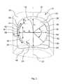
- FIG. 2is a cross-sectional view of the intramedullary nail embodiment taken along line A-A in FIG. 1
- FIG. 3is an enlarged view of detail Y of the intramedullary nail embodiment shown in FIG. 1 ;
- FIG. 4is a perspective side view of the proximal portion of the intramedullary nail embodiment shown in FIG. 1 ;
- FIG. 5is a view of detail Z of the intramedullary nail embodiment shown in FIG. 2 ;
- FIG. 6is a cross-sectional view of the intramedullary nail embodiment taken along line C-C in FIG. 1 ;
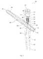
- FIG. 7is a cross-sectional view of an implant system embodiment that is based on the intramedullary nail embodiment shown in FIGS. 1 and 2 .
- FIG. 1there is shown a lateral side view of an embodiment of an intramedullary nail 10 for use in orthopaedic surgery for fixation of bone, such as a femur (not shown in FIG. 1 ).
- the intramedullary nail 10is made of a biocompatible material such as stainless steel, titanium or a titanium alloy.
- the intramedullary nail 10includes a rod-shaped body insertable into the inner cavity of a bone (marrow cavity), e.g., into the intramedullary canal of a femur.
- the intramedullary nail 10includes a proximal portion 12 , a distal portion 14 and an intermediate portion 16 therebetween.
- the intermediate portion 16connects the proximal portion 12 with the distal portion 14 .
- the intramedullary nail 10tapers in a direction from the proximal portion 12 to the distal portion 14 .
- the distal portionis longer than the proximal portion 12 .
- the intermediate portion 16 located between the proximal portion 12 and the distal portion 14is bent for anatomical reasons.
- the intramedullary nail 10has a substantially circular cross-section over its entire length.
- the proximal portion 12 and the distal portion 14 of the intramedullary nail 10have a substantially cylindrical shape.
- the proximal portion 12 of the intramedullary nail 10has a diameter sufficient to accommodate a transverse bore 20 therein. While in the present embodiment only a single transverse bore 20 is present, in other embodiments multiple (e.g., two or more) similar transverse bores may be provided in the proximal portion 12 .
- the distal portion 14has a smaller diameter than the proximal portion 12 , adapted to the shape of the marrow cavity of the femur in order to facilitate the insertion of the distal portion 14 into the intramedullary canal.
- the distal portion 14has a conical tip portion 18 at its distal end.
- the intermediate portion 16 connecting the proximal portion 12 and the distal portion 14substantially tapers in a direction from the proximal portion 12 to the distal portion 14 .
- the proximal portion 12 of the intramedullary nail 10defines a longitudinal axis 22 and includes a connecting portion in form of a recess 24 for receiving an end cap or a surgical tool, such as a holding instrument or targeting instrument (not shown in FIG. 1 ) at the upper rim of the proximal portion 12 .
- the distal portion 14likewise defines a longitudinal axis 26 which is angled with respect to the longitudinal axis 22 of the proximal portion 12 . Further, the distal portion 14 includes an opening 28 in form of an elongated through hole.
- the elongated through hole 28is formed at an end of the distal portion 14 of the intramedullary nail 10 for receiving a bone fastener, such as a connecting fastener (e.g., a locking screw).
- a bone fastenersuch as a connecting fastener (e.g., a locking screw).
- the bone fasteneris used to fasten and securely fix the intramedullary nail 10 to bone.
- the intramedullary nail 10has a cannulation channel 30 axially extending through the intramedullary nail 10 .
- the channel 30may receive a surgical wire (not shown in FIG. 1 ), such as a Kirschner wire, for guiding the intramedullary nail 10 to and through the bone.
- the transverse bore 20 located at the proximal portion 12has flattened and rounded edge portions 32 and 34 .
- the transverse bore 20includes two recesses 36 , or pockets, formed at an inner wall 38 of the transverse bore 20 .
- Each of the two recesses 36substantially extends along the transverse bore 20 .
- each of the two recessessubstantially extends from a lateral side towards a medial side of the intramedullary nail 10 and may extend completely through the bore.
- medial and lateralare standard anatomical terms of direction and denote a direction toward the center of a median plane of a body and the opposite direction from the center to the side, respectively.
- the medial and lateral directionsmay generally lie within a plane including the longitudinal axis 22 of the proximal portion 12 (or the longitudinal axis of the intramedullary nail 10 ) and an axis of the transverse bore 20 .
- the medial side of the intramedullary nail 10may be a side facing towards the outgoing side of the transverse bore 20 (e.g., towards a tip of a bone engagement member penetrating the transverse bore 20 ), whereas the lateral side may be a side facing towards the ingoing side of the transverse bore 20 (e.g., towards a head of the bone engagement member).
- the intramedullary nail 10is anatomically shaped so that the intramedullary nail 10 inherently defines the medial and lateral sides, for example with respect to its bent portion (e.g., as embodied by the bent intermediate portion 16 of the intramedullary nail 10 ) resulting in an inclination of the transverse bore 20 .
- FIG. 2shows a cross-sectional view of the intramedullary nail embodiment shown in FIG. 1 along the line A-A, i.e., along an imaginary longitudinal axis of the intramedullary nail 10 .
- the proximal portion 12 of the intramedullary nail 10includes a compartment 40 for reception of an interlocking pin or set screw (both not shown in FIG. 2 ) that engages a bone engagement member received by the transverse bore 20 .
- the compartment 40 of the proximal portion 12is co-axial with the longitudinal axis 22 of the proximal portion 12 .
- the compartment 40may include an internal thread which mates with a corresponding thread of a set screw.
- the compartment 40opens out in a distal direction into the transverse bore 20 of the proximal portion 12 .
- a bore axis 42 of the transverse bore 20is angled with respect to the longitudinal axis 22 of the proximal portion 12 , such that the longitudinal axis 22 of the transverse bore 20 has an oblique extension relative to an axial extension of the proximal portion 12 .
- the bore axisis oriented obliquely with respect to the longitudinal axis 22 of the proximal portion 12 .
- the bore axis 42 of the transverse bore 20is inclined at an angle ⁇ with respect to the longitudinal axis 22 of the proximal portion 12 .
- the bore axis 42 of the transverse bone 20is further inclined at an angle ⁇ with respect to the longitudinal axis 26 of the distal portion 14 .
- These angles ⁇ and ⁇may lie between 50° and 150°.
- the angle ⁇ of the bore axis 42 of the transverse bore 20 with respect to the longitudinal axis 22 of the proximal portion 12may lie between 90° and 140°.
- the angle ⁇ of the bore axis 42 of the transverse bore 20 with respect to the longitudinal axis 26 of the distal portion 26may lie between 90° and 140° as well.
- the angle ⁇is approximately 126° and the angle ⁇ is approximately 130°.
- the transverse bone 20 of the proximal portion 12substantially extends in a direction from a lateral side to a medial side of the intramedullary nail 10 .
- the transverse bore 20has an inlet opening 44 and an outlet opening 46 for the bone engagement member (not shown in FIG. 2 ).
- the inlet opening 44faces away from the head of the femur when the intramedullary nail 10 has been driven into the bone canal.
- each of the two recesses 36opens out into the inlet opening 44 of the transverse bore 20 .
- FIG. 3illustrates a detailed side view of the transverse bore 20 of the proximal portion 12 denoted by Y in FIG. 1 .
- FIG. 4illustrates a perspective view thereof.
- the inlet opening 44opens out into a notch, or depression, defined by the outer rounded edge 32 and the flattened edge 34 .
- the depressionhas an approximately square contour with rounded corners.
- An outer edge of the depressionis located in the outer contour of the proximal portion 12 .
- An inner edge 50 of the depressionis located within the outer edge 48 and defines the inlet opening 44 .
- surface portions which partially are beveled or chamferedare formed between the outer edge 48 and the inner edge 50 of the notch.
- each of the recesses 36has generally a concave shape in cross-section. Further, one of the two recesses 36 is arranged on the posterior side (e.g., the left side in FIG. 3 ) and the other recess 36 is arranged on the anterior side (e.g., the right side in FIG. 3 ) of the intramedullary nail 10 , i.e., on the posterior side and the anterior side of the transverse bore 20 , respectively. In other words, the two recesses 36 of the transverse bore 20 are arranged across from each other on opposite sides of the bore axis 42 of the transverse bore 20 .
- anterior and posteriorare standard anatomical terms of direction and denote a direction toward the front of a body (ventral) and the opposite direction toward the back of the body (dorsal), respectively.
- the anterior and posterior directionsmay generally lie within a plane including the longitudinal axis 22 of the proximal portion 12 and a diameter of the transverse bore 20 .
- an intramedullary nailwill be anatomically configured so that the intramedullary nail inherently defines the anterior and posterior sides.
- each recess 36 formed at the inner wall 38 of the transverse bore 20defines an arc segment 52 in cross-section.
- the arc segment 52 of each recess 36extends over an angle ⁇ with respect to the bore axis 42 of the transverse bore 20 .
- the angle ⁇ of the arc segment 52can lie between 5° and 175°.
- the angle ⁇ of the arc segmentmay lie between 45° and 120°, and is in the present embodiment approximately 80°.
- each of the two recesses 36has a width wr along the arc segment 52 .
- the width wr along the arc segment 52 of each recess 36may between 2 mm and 14 mm. In the present embodiment, the width wr is approximately 8 mm.
- each arc segment 52is defined by three (or, in other embodiments, more or less) radii R 1 , R 2 and R 3 which define the concave shape of the recess 36 .
- the cross-section of each recess 36can be divided into three regions separated from each other along the arc segment.
- each recess 36has an intermediate region 54 and two outer regions 56 adjacent thereto.
- the intermediate region 54 of the recess 36is defined by a circle which has a radius R 1 .
- the radius R 1can lie between 1.0 mm and 20.0 mm, preferably between 3.0 mm and 10.0 mm, and is in the present embodiment approximately 5.2 mm.
- each recess 36are defined by a radius R 2 and radius R 3 respectively.
- the radii R 2 and R 3can be different from each other or, as in the present embodiment, equal.
- the radii R 2 and R 3can lie between 1.0 mm and 20.0 mm, preferably between 1.0 mm and 7.0 mm, and are both in the present embodiment approximately 2.0 mm.
- the transverse bore 20defines a first diameter d 1 which is oriented substantially parallel to the longitudinal axis 22 of the proximal portion 12 (i.e., the first diameter d 1 is oriented in a direction from the proximal side to the distal side of the intramedullary nail 10 ).
- the transverse bore 20further defines a second diameter d 2 which is oriented substantially perpendicular to the longitudinal axis 22 of the proximal portion 12 (i.e., the second diameter d 2 is oriented in a direction from a posterior side to the anterior side of the intramedullary nail 10 ). As shown in FIGS.
- the second diameter d 2is greater than the first diameter d 1 in at least a portion of the transverse bore 20 .
- the second diameter d 2is greater than the first diameter d 1 (i.e., in the lateral/medical plane of the intramedullary nail 10 ).
- FIG. 5shows a detailed cross-sectional view of the transverse bore 20 of the proximal portion 12 denoted by Z in FIG. 2 .
- the lateral side of the intramedullary nail 10is on the right side and the medial side of the intramedullary nail 10 is on the left side of the drawing.
- each of the two recesses 36defines a length lr along the inner wall 38 in a direction of the bore axis 42 of the transverse bore 20 .
- the length lr of each recess 36is less than the length of the transverse bore 20 along the bore axis 42 .
- the length lr of each recess 36may lie between 1 mm and 10 mm, preferably between 2 mm and 7 mm, and is approximately 5.3 mm in the present embodiment.
- the intermediate region 54 of each recess 36defines a width wi which is oriented in a direction substantially perpendicular to the bore axis 42 .
- the width wi of the intermediate region 54 of the recess 36is oriented substantially parallel to the longitudinal axis 22 of the proximal portion 12 .
- the width wi of each recess 36may lie between 2 mm and 9 mm, preferably between 3 mm and 5 mm. In the present embodiment, the width wi of the intermediate region 54 of each recess 36 is approximately 4.4 mm.
- each of the two recesses 36has an oblique extension relative to an extension of the bore axis 42 of the transverse bore 20 .
- the outer regions 56 of the recess 36taper towards the center line of the bore in a direction from the inlet opening 44 toward the outlet opening 46 of the transverse bore 20 (in this case, in the plane of the drawing of FIG. 5 ).
- FIG. 6illustrates a cross sectional view of the transverse bore 20 of the proximal portion 12 along line C-C shown in FIG. 1 .
- each recess 36has a conical shape in the direction of the bore axis 42 of the transverse bore 20 (in this case, in the plane of the drawing of FIG. 6 ).
- Each recess 36defines a taper with a cone angle c with respect to the inner wall 38 of the transverse bore 20 .
- the cone angle ccan lie between 1° and 10°, preferably between 2° and 5°.In the present embodiment, the cone angle c of each recess 36 is approximately 3.8°.
- the cone angle clies within a plane including the bore axis 42 of the transverse bore 20 and the diameter d 2 of the transverse bore 20 (i.e., a plane which is perpendicular to the longitudinal axis 22 of the proximal portion 12 ).
- Each recess 36tapes substantially in a direction from the inlet opening 44 toward the outlet opening 46 of the transverse bore 20 .
- the recesses 36widen in a direction toward the inlet opening 44 of the transverse bore 20 .
- the two recesses 36widen the transverse bore 20 , on the one hand, in a direction of the bore axis 42 of the transverse bore 20 and, on the other hand, in a direction of the longitudinal axis 22 of the proximal portion 12 , in both cases, toward the inlet opening 44 of the transverse bore 20 .
- the recesses 36help to reduce the probability of nail breakage in the region of the transverse bore 20 . Especially in cases in which the inner wall 38 of the transverse bore 20 gets damaged (e.g., by a drill operation through the transverse bore 20 ) the rate of nail breakages can be reduced. This reduction can be attributed to smaller material tensions in a region of the intramedullary nail 10 around the transverse bore 20 due to the presence of recesses 36 .
- FIG. 7there is shown a cross-sectional view of an embodiment of an implant system 58 for use in orthopaedic surgery for fixation of bone, such as a femur (not shown in FIG. 7 ).
- the implant system 58comprises the intramedullary nail 10 as described above with reference to FIGS. 1 to 6 .
- the implant system 58further includes a bone fastener 60 (that forms a bone engagement member) and a coupling unit 62 which may be an anti-rotation screw which permits compressive sliding.
- the bone fastener 60is configured to penetrate the transverse bore 20 of the intramedullary nail 10 from the inlet opening 44 to the outlet opening 46 .
- the coupling unit 62couples the bone fastener 60 to the intramedullary nail 10 .
- the bone fastener 60is a sliding screw (e.g., femoral neck screw or lag screw), with a front portion 64 including a thread, for example a coarse thread, and a rear portion 66 .
- the rear portion 66is provided with a plurality of longitudinally extending grooves 68 (two are shown in FIG. 7 ) arranged on the peripheral surface of the rear portion 66 along a longitudinal axis of the sliding screw 60 .
- four grooves 68are disposed on the peripheral surface of the sliding screw 60 at intervals of 90° around the longitudinal axis of the sliding screw 60 .
- Each groove 68defines a ramp having a shallow end and a deeper end. The rising ramp extends from the end of the rear portion 66 towards the threaded front portion.
- the sliding screw 60includes a central cannulation 70 along the longitudinal axis of the sliding screw 60 .
- the rear portion 66 of the sliding screw 60includes at its free end a co-axial bore 72 and a recess 74 (e.g., a hexalobular internal driving feature) for receiving a tool tip (e.g., of screw driver or a wrench).
- the unthreaded rear portion 66 of the sliding screw 60is slidably received in the transverse bore of the proximal portion 12 of the intramedullary nail 10 .
- the bore axis 42 of the transverse bore 20is substantially parallel to the longitudinal axis of the sliding screw 60 .
- the bore axis 42is congruent with the longitudinal axis of the sliding screw 60 . The sliding screw 60 can thus transfer the load of the femoral head into the intramedullary nail 10 and at the same time bridges the fracture line to allow fast and secure fracture healing.
- the coupling unit 62is realized as a set screw which is preassembled and movably arranged within the proximal portion 12 of the intramedullary nail 10 .
- the coupling unit 62includes one bone fastener engagement member 76 and a drive member 78 .
- the engagement member 76 of the coupling unit 62is centrally positioned within the bore 40 of the proximal portion 12 .
- the engagement member 76is realized in the exemplary form of a substantially cylindrical bolt, pin or protrusion.
- the drive member 78 of the coupling unit 62is connected to the engagement member 76 and includes an external thread for threadable engagement with the intramedullary nail 10 (e.g., with the proximal portion 12 as shown in FIG. 7 ).
- the bore 40 of the proximal portion 12includes an internal thread which mates with the external thread of the drive member 78 of the coupling unit 62 .
- the drive member 76 of the coupling unit 62is movably arranged within the bore 40 of the proximal portion 12 of the intramedullary nail 10 .
- the coupling unit 62is captively held within the proximal portion 12 of the intramedullary nail 10 . As illustrated in FIG.
- the engagement member 76 of the coupling unit 62can engage within a groove 68 of the sliding screw 60 .
- the engagement member 76can exert pressure on the sliding screw 60 for stabilization purposes.
- the pressureis initially zero or low enough to still permit a sliding movement of the sliding screw 60 relative to the intramedullary nail 10 .
- the pressurewill change (and typically increase) as the sliding screw 60 slides due to the depth profile (i.e., the lateral and medial ramps) of the grooves 68 .
- Rotation of the drive member 78 of the coupling unit 62causes movement of the engagement member 76 along the longitudinal axis 22 of the proximal portion 12 .
- the drive member 78 of the coupling unit 62has a receiving portion 80 in form of a recess (e.g., realized as a hexalobular internal driving feature) for receiving a tool such as a screw driver or wrench.
- a toolsuch as a screw driver or wrench.
- the position of the coupling unit 62 , and thus the position of its engagement member 76 , within the proximal portion 12 of the intramedullary nail 10can be adjusted by screwing the drive member 78 of the coupling unit 62 along the longitudinal axis 22 of the proximal portion 12 .
- a manufacturing process for modifying a notch (or depression) formed around the neck screw borei.e., the transverse bore arranged in the proximal portion of the intramedullary nail
- the processmay be performed before or after the notch is formed around the predrilled femoral neck screw bore in accordance with, for example, the aforementioned U.S. Pat. No. 7,763,022 B2.
- the processmay also be performed without formation of such a notch.
- a cone shaped pocket, i.e., a recess 36is formed on both the anterior and posterior side of the bore although the formation of only one cone-shaped pocket will be described.
- a central axis of a mill cutter headis aligned with the axis 42 of the neck screw bore 20 (i.e., the transverse bore 20 of the proximal portion 12 of the nail 10 ).
- the bore 20may be angled at about 126° to the longitudinal axis 22 of the proximal portion 12 of the intramedullary nail 10 .
- the mill cutter axisis placed at the neck screw entry side (i.e., the lateral side) of the intramedullary nail 10 and is then angled in at least one plane, for example at an angle of about 3.8° to a first plane containing both the proximal nail axis 22 and the neck screw bore axis 42 .
- the cutter headis then moved in two elliptical paths to form a conically tapered recess 36 having a curved inwardly facing surface.
- the curved surfaceextends proximally and distally of a second plane containing the axis 42 of the screw bore 20 and perpendicular to the first plane.
- the proximal and distal foci of the two ellipsesare located, for example, about 1.2 mm proximal and about 2.2 mm distal of the second plane.
- the curved surfaceis formed by moving the mill head along a spline connecting end portions of the two ellipses since the foci are spaced at different distances from the first plane.
- the mill head cutting pathforms a tangent with each ellipse end portion.
- the rod-shaped body of the intramedullary nailincludes a distal portion, a proximal portion and an intermediate (bent) portion therebetween
- the nail bodycan be adapted as needed (e.g., in terms of shape, length, width, thickness, etc.) for use in orthopaedic surgery for fixation of bone and for insertion into an intramedullary canal of, e.g., a femur.
- the shape of the intramedullary nailcan be adapted to different applications.
- the bone engagement member(bone fastener) described herein is formed as a sliding screw or a lag screw
- the bone engagement membercan be of any type (e.g., a femoral neck screw or any kind of blade) and can be adapted to different applications as needed.
- one or more bone engagement memberse.g., two, three or more bone fasteners
- the implantmay have two or more transverse openings and two or more sliding screws arranged therein in a manner as shown in FIG. 7 .
- the bone engagement members as well as the connecting fastener(s)may have different diameters, lengths, shapes or threads.
Landscapes
- Health & Medical Sciences (AREA)
- Orthopedic Medicine & Surgery (AREA)
- Life Sciences & Earth Sciences (AREA)
- Surgery (AREA)
- Engineering & Computer Science (AREA)
- Heart & Thoracic Surgery (AREA)
- Nuclear Medicine, Radiotherapy & Molecular Imaging (AREA)
- Biomedical Technology (AREA)
- Medical Informatics (AREA)
- Molecular Biology (AREA)
- Animal Behavior & Ethology (AREA)
- General Health & Medical Sciences (AREA)
- Public Health (AREA)
- Veterinary Medicine (AREA)
- Neurology (AREA)
- Mechanical Engineering (AREA)
- Surgical Instruments (AREA)
Abstract
Description
Claims (20)
Priority Applications (1)
| Application Number | Priority Date | Filing Date | Title |
|---|---|---|---|
| US14/682,457US9358049B2 (en) | 2012-10-01 | 2015-04-09 | Intramedullary nail and implant system comprising the nail |
Applications Claiming Priority (3)
| Application Number | Priority Date | Filing Date | Title |
|---|---|---|---|
| EP12006837.4AEP2712562B1 (en) | 2012-10-01 | 2012-10-01 | Intramedullary nail and implant system comprising the nail |
| EP12006837 | 2012-10-01 | ||
| EP12006837.4 | 2012-10-01 |
Related Child Applications (1)
| Application Number | Title | Priority Date | Filing Date |
|---|---|---|---|
| US14/682,457DivisionUS9358049B2 (en) | 2012-10-01 | 2015-04-09 | Intramedullary nail and implant system comprising the nail |
Publications (2)
| Publication Number | Publication Date |
|---|---|
| US20140094802A1 US20140094802A1 (en) | 2014-04-03 |
| US9072552B2true US9072552B2 (en) | 2015-07-07 |
Family
ID=47080135
Family Applications (2)
| Application Number | Title | Priority Date | Filing Date |
|---|---|---|---|
| US13/763,858Active2033-07-01US9072552B2 (en) | 2012-10-01 | 2013-02-11 | Intramedullary nail and implant system comprising the nail |
| US14/682,457ActiveUS9358049B2 (en) | 2012-10-01 | 2015-04-09 | Intramedullary nail and implant system comprising the nail |
Family Applications After (1)
| Application Number | Title | Priority Date | Filing Date |
|---|---|---|---|
| US14/682,457ActiveUS9358049B2 (en) | 2012-10-01 | 2015-04-09 | Intramedullary nail and implant system comprising the nail |
Country Status (6)
| Country | Link |
|---|---|
| US (2) | US9072552B2 (en) |
| EP (1) | EP2712562B1 (en) |
| JP (1) | JP6235025B2 (en) |
| CN (1) | CN104736079B (en) |
| ES (1) | ES2548045T3 (en) |
| WO (1) | WO2014053438A1 (en) |
Cited By (14)
| Publication number | Priority date | Publication date | Assignee | Title |
|---|---|---|---|---|
| US20170333096A1 (en)* | 2014-11-25 | 2017-11-23 | Swemac Innovation Ab | Intramedullary nail |
| US9895177B2 (en) | 2016-01-15 | 2018-02-20 | ARTHREX, GmbH | Bone fixation device for treatment of femoral fractures |
| US20180146992A1 (en)* | 2015-05-22 | 2018-05-31 | Stryker European Holdings l, LLC | Implant system for bone fixation |
| US20180250041A1 (en)* | 2016-09-22 | 2018-09-06 | Globus Medical, Inc. | Systems and methods for intramedullary nail implantation |
| US10492803B2 (en) | 2016-09-22 | 2019-12-03 | Globus Medical, Inc. | Systems and methods for intramedullary nail implantation |
| US10758280B2 (en) | 2017-10-09 | 2020-09-01 | Acumed Llc | System and method for bone fixation using a nail locked to an encircling anchor |
| WO2021176272A1 (en) | 2020-03-06 | 2021-09-10 | Stryker European Operations Limited | Set screw for femoral nail |
| US20220151664A1 (en)* | 2015-04-16 | 2022-05-19 | Texas Tech University System | Ankle (Tibio-Talar) Fusion Nail |
| US11446072B2 (en) | 2017-10-10 | 2022-09-20 | DePuy Synthes Products, Inc. | Self-retaining nail to insertion handle interface |
| US11633219B2 (en) | 2019-06-26 | 2023-04-25 | Globus Medical, Inc. | Fenestrated pedicle nail |
| US11819253B2 (en) | 2020-05-29 | 2023-11-21 | Stryker European Operations Limited | Funnel hole for intramedullary nail |
| EP4311509A1 (en)* | 2022-07-28 | 2024-01-31 | Globus Medical, Inc. | Retrograde femoral nail system |
| US12004785B2 (en) | 2022-04-21 | 2024-06-11 | DePuy Synthes Products, Inc. | Retrograde femoral intramedullary nail, and related systems and methods |
| US12207849B2 (en) | 2020-03-06 | 2025-01-28 | Stryker European Operations Limited | Set screw for femoral nail |
Families Citing this family (15)
| Publication number | Priority date | Publication date | Assignee | Title |
|---|---|---|---|---|
| CA2825444C (en) | 2011-02-08 | 2016-01-12 | Stryker Trauma Gmbh | Implant system for bone fixation |
| DE102013005414A1 (en)* | 2013-03-28 | 2014-10-02 | Dietmar Wolter | Osteosynthesis system for the multidirectional, angularly stable treatment of fractures of long bones including an intramedullary nail and bone screws |
| US9526542B2 (en)* | 2014-05-07 | 2016-12-27 | Acumed Llc | Hip fixation with load-controlled dynamization |
| US9433451B2 (en) | 2013-12-09 | 2016-09-06 | Acumed Llc | Hip fixation system with a compliant fixation element |
| US10080596B2 (en) | 2013-12-09 | 2018-09-25 | Acumed Llc | Hip fixation with load-controlled dynamization |
| US9463055B2 (en) | 2013-12-09 | 2016-10-11 | Acumed Llc | Plate-based compliant hip fixation system |
| ES2805053T3 (en) | 2013-12-09 | 2021-02-10 | Acumed Llc | Nail-based elastic hip fixation system |
| DE102014113556A1 (en)* | 2014-09-19 | 2016-03-24 | Königsee Implantate GmbH | Osteosynthesis aids for the treatment of subtrochanteric fractures and / or pertrochanteric fractures and / or femoral neck fractures |
| BR112018007347A2 (en)* | 2015-10-16 | 2018-10-23 | Nuvasive Specialized Orthopedics, Inc. | adjustable devices for the treatment of knee arthritis |
| US10299847B2 (en)* | 2016-09-22 | 2019-05-28 | Globus Medical, Inc. | Systems and methods for intramedullary nail implantation |
| CN106618710A (en)* | 2017-02-20 | 2017-05-10 | 广东工业大学 | Proximal fixation intramedullary nail matched with femur medullary cavity in shape |
| CN112353475B (en)* | 2020-11-06 | 2025-03-07 | 陈聚伍 | Femoral trochanteric fracture fixation device |
| CN113229915B (en)* | 2021-04-21 | 2022-12-13 | 天津市金兴达实业有限公司 | Intramedullary pin |
| CN113146164B (en)* | 2021-04-30 | 2022-12-02 | 宁波兆盈医疗器械有限公司 | Tibial intramedullary nail machining process |
| CN116000673B (en)* | 2023-02-01 | 2023-09-19 | 常州健力邦德医疗器械有限公司 | Intramedullary nail processing equipment and method |
Citations (31)
| Publication number | Priority date | Publication date | Assignee | Title |
|---|---|---|---|---|
| US3433220A (en)* | 1966-12-30 | 1969-03-18 | Robert E Zickel | Intramedullary rod and cross-nail assembly for treating femur fractures |
| US5176681A (en) | 1987-12-14 | 1993-01-05 | Howmedica International Inc. | Intramedullary intertrochanteric fracture fixation appliance and fitting device |
| US5454813A (en) | 1991-06-24 | 1995-10-03 | Howmedica International Inc. | Intramedullary intertrochanteric fracture fixation appliance |
| US5733287A (en) | 1994-05-24 | 1998-03-31 | Synthes (U.S.A.) | Bone plate |
| US6123708A (en)* | 1999-02-03 | 2000-09-26 | Pioneer Laboratories, Inc. | Intramedullary bone fixation rod |
| US20030171819A1 (en)* | 2002-03-11 | 2003-09-11 | Sotereanos Nicholas G. | Modular hip implants |
| US20040172027A1 (en)* | 2003-02-07 | 2004-09-02 | Stryker Trauma Gmbh | Locking nail for treating fractures of the proximal femur |
| US20060084999A1 (en) | 2003-04-09 | 2006-04-20 | Felix Aschmann | Intramedullary nail for femur fracture fixation |
| US20060095039A1 (en)* | 2004-01-20 | 2006-05-04 | Mutchler Austin W | Intramedullary nail and associated method |
| US20060200160A1 (en)* | 2005-02-18 | 2006-09-07 | Ebi, L.P. | Internal fixation assemblies and associated instruments |
| US20060241604A1 (en) | 2003-09-18 | 2006-10-26 | Robert Frigg | Device for the treatment of femoral fractures |
| WO2007038560A1 (en) | 2005-09-28 | 2007-04-05 | Smith & Nephew, Inc. | Instrumentation for reducing fractures , particularly femoral neck |
| WO2007048038A2 (en) | 2005-10-21 | 2007-04-26 | Acumed Llc | Orthopedic rod with locking aperture |
| US20080195098A1 (en)* | 2007-02-09 | 2008-08-14 | Yechiel Gotfried | Intramedullary nail system and method for fixation of a fractured bone |
| US20080221574A1 (en)* | 2007-03-05 | 2008-09-11 | Cesare Cavallazzi | Method of Treating a Clavicle Fracture |
| US7527627B2 (en) | 2003-09-08 | 2009-05-05 | Smith & Nephew, Inc. | Orthopaedic implant and screw assembly |
| US20090222049A1 (en)* | 2005-11-16 | 2009-09-03 | Robert Frigg | Device for Bone Fixation with at least one Through Hole |
| US20100174284A1 (en) | 2008-10-15 | 2010-07-08 | Zimmer, Gmbh | Intramedullary nail |
| US20100179551A1 (en)* | 2007-05-25 | 2010-07-15 | Zimmer, Gmbh | Reinforced intramedullary nail |
| US7780667B2 (en) | 2003-09-08 | 2010-08-24 | Smith & Nephew, Inc. | Orthopaedic plate and screw assembly |
| WO2011044917A1 (en) | 2009-10-13 | 2011-04-21 | Zimmer Gmbh | An orthopedic nail and an orthopedic nail system |
| USD638125S1 (en)* | 2010-04-13 | 2011-05-17 | Zimmer, Gmbh | Intramedullary nail |
| USD638126S1 (en)* | 2010-04-13 | 2011-05-17 | Zimmer, Gmbh | Intramedullary nail |
| US20110160729A1 (en)* | 2009-07-01 | 2011-06-30 | Tom Overes | Intramedullary Nail and Protruding Screw Locking Mechanism |
| US8034056B2 (en)* | 2004-07-15 | 2011-10-11 | Wright Medical Technology, Inc. | Guide assembly for intramedullary fixation and method of using the same |
| US20120197255A1 (en)* | 2007-01-26 | 2012-08-02 | Biomet Manufacturing Corp. | Lockable Intramedullary Fixation Device |
| US8313487B2 (en)* | 2008-06-24 | 2012-11-20 | Extremity Medical Llc | Fixation system, an intramedullary fixation assembly and method of use |
| US8328806B2 (en)* | 2008-06-24 | 2012-12-11 | Extremity Medical, Llc | Fixation system, an intramedullary fixation assembly and method of use |
| US8449544B2 (en)* | 2009-06-30 | 2013-05-28 | Smith & Nephew, Inc. | Orthopaedic implant and fastener assembly |
| US20130274745A1 (en)* | 2012-04-16 | 2013-10-17 | DePuy Synthes Products, LLC | Bump cut on hole edge |
| US20140012259A1 (en)* | 2011-12-15 | 2014-01-09 | Anthem Orthopaedics Van, Llc | Implantable device with locking adjustment mechanism and method for using same |
Family Cites Families (3)
| Publication number | Priority date | Publication date | Assignee | Title |
|---|---|---|---|---|
| WO2004039270A1 (en)* | 2002-10-29 | 2004-05-13 | Mathys Medizinaltechnik Ag | Device for the treatment of fractures of the femur |
| CN101601605B (en)* | 2009-07-14 | 2011-01-05 | 常州市康辉医疗器械有限公司 | Intramedullary nail fixation device for fractured near end of thighbone |
| EP2926750B1 (en)* | 2014-03-31 | 2017-04-26 | Zimmer GmbH | Intramedullary nail assembly |
- 2012
- 2012-10-01EPEP12006837.4Apatent/EP2712562B1/enactiveActive
- 2012-10-01ESES12006837.4Tpatent/ES2548045T3/enactiveActive
- 2013
- 2013-02-11USUS13/763,858patent/US9072552B2/enactiveActive
- 2013-09-30WOPCT/EP2013/070332patent/WO2014053438A1/enactiveApplication Filing
- 2013-09-30JPJP2015533626Apatent/JP6235025B2/enactiveActive
- 2013-09-30CNCN201380049425.5Apatent/CN104736079B/enactiveActive
- 2015
- 2015-04-09USUS14/682,457patent/US9358049B2/enactiveActive
Patent Citations (35)
| Publication number | Priority date | Publication date | Assignee | Title |
|---|---|---|---|---|
| US3433220A (en)* | 1966-12-30 | 1969-03-18 | Robert E Zickel | Intramedullary rod and cross-nail assembly for treating femur fractures |
| US5176681A (en) | 1987-12-14 | 1993-01-05 | Howmedica International Inc. | Intramedullary intertrochanteric fracture fixation appliance and fitting device |
| US5454813A (en) | 1991-06-24 | 1995-10-03 | Howmedica International Inc. | Intramedullary intertrochanteric fracture fixation appliance |
| US5733287A (en) | 1994-05-24 | 1998-03-31 | Synthes (U.S.A.) | Bone plate |
| US6123708A (en)* | 1999-02-03 | 2000-09-26 | Pioneer Laboratories, Inc. | Intramedullary bone fixation rod |
| US20030171819A1 (en)* | 2002-03-11 | 2003-09-11 | Sotereanos Nicholas G. | Modular hip implants |
| US20040172027A1 (en)* | 2003-02-07 | 2004-09-02 | Stryker Trauma Gmbh | Locking nail for treating fractures of the proximal femur |
| US7763022B2 (en) | 2003-02-07 | 2010-07-27 | Stryker Trauma Gmbh | Locking nail for treating fractures of the proximal femur |
| US20060084999A1 (en) | 2003-04-09 | 2006-04-20 | Felix Aschmann | Intramedullary nail for femur fracture fixation |
| US7527627B2 (en) | 2003-09-08 | 2009-05-05 | Smith & Nephew, Inc. | Orthopaedic implant and screw assembly |
| US7780667B2 (en) | 2003-09-08 | 2010-08-24 | Smith & Nephew, Inc. | Orthopaedic plate and screw assembly |
| US20060241604A1 (en) | 2003-09-18 | 2006-10-26 | Robert Frigg | Device for the treatment of femoral fractures |
| US20060095039A1 (en)* | 2004-01-20 | 2006-05-04 | Mutchler Austin W | Intramedullary nail and associated method |
| US8034056B2 (en)* | 2004-07-15 | 2011-10-11 | Wright Medical Technology, Inc. | Guide assembly for intramedullary fixation and method of using the same |
| US20060200160A1 (en)* | 2005-02-18 | 2006-09-07 | Ebi, L.P. | Internal fixation assemblies and associated instruments |
| WO2007038560A1 (en) | 2005-09-28 | 2007-04-05 | Smith & Nephew, Inc. | Instrumentation for reducing fractures , particularly femoral neck |
| US20080249580A1 (en)* | 2005-09-28 | 2008-10-09 | Smith & Nephew, Inc. | Methods and Instruments of Reducing a Fracture |
| WO2007048038A2 (en) | 2005-10-21 | 2007-04-26 | Acumed Llc | Orthopedic rod with locking aperture |
| US20090222049A1 (en)* | 2005-11-16 | 2009-09-03 | Robert Frigg | Device for Bone Fixation with at least one Through Hole |
| US20120197255A1 (en)* | 2007-01-26 | 2012-08-02 | Biomet Manufacturing Corp. | Lockable Intramedullary Fixation Device |
| US20080195098A1 (en)* | 2007-02-09 | 2008-08-14 | Yechiel Gotfried | Intramedullary nail system and method for fixation of a fractured bone |
| US20080221574A1 (en)* | 2007-03-05 | 2008-09-11 | Cesare Cavallazzi | Method of Treating a Clavicle Fracture |
| US20100179551A1 (en)* | 2007-05-25 | 2010-07-15 | Zimmer, Gmbh | Reinforced intramedullary nail |
| US8313487B2 (en)* | 2008-06-24 | 2012-11-20 | Extremity Medical Llc | Fixation system, an intramedullary fixation assembly and method of use |
| US8328806B2 (en)* | 2008-06-24 | 2012-12-11 | Extremity Medical, Llc | Fixation system, an intramedullary fixation assembly and method of use |
| US20100174284A1 (en) | 2008-10-15 | 2010-07-08 | Zimmer, Gmbh | Intramedullary nail |
| US8668695B2 (en)* | 2008-10-15 | 2014-03-11 | Zimmer Gmbh | Intramedullary nail |
| US8449544B2 (en)* | 2009-06-30 | 2013-05-28 | Smith & Nephew, Inc. | Orthopaedic implant and fastener assembly |
| US20110160729A1 (en)* | 2009-07-01 | 2011-06-30 | Tom Overes | Intramedullary Nail and Protruding Screw Locking Mechanism |
| US20120265202A1 (en)* | 2009-10-13 | 2012-10-18 | Zimmer Gmbh | Orthopedic nail and an orthopedic nail system |
| WO2011044917A1 (en) | 2009-10-13 | 2011-04-21 | Zimmer Gmbh | An orthopedic nail and an orthopedic nail system |
| USD638126S1 (en)* | 2010-04-13 | 2011-05-17 | Zimmer, Gmbh | Intramedullary nail |
| USD638125S1 (en)* | 2010-04-13 | 2011-05-17 | Zimmer, Gmbh | Intramedullary nail |
| US20140012259A1 (en)* | 2011-12-15 | 2014-01-09 | Anthem Orthopaedics Van, Llc | Implantable device with locking adjustment mechanism and method for using same |
| US20130274745A1 (en)* | 2012-04-16 | 2013-10-17 | DePuy Synthes Products, LLC | Bump cut on hole edge |
Non-Patent Citations (2)
| Title |
|---|
| Extended European Search Report for Application No. EP12006837 dated Feb. 8, 2013. |
| Orthopaedic Biomechanics Laboratory, Biomechanical Testing of Femoral Intramedullary Devices, pp. 1-14, Jun. 1996. |
Cited By (23)
| Publication number | Priority date | Publication date | Assignee | Title |
|---|---|---|---|---|
| US10398482B2 (en)* | 2014-11-25 | 2019-09-03 | Swemac Innovation Ab | Intramedullary nail |
| US20170333096A1 (en)* | 2014-11-25 | 2017-11-23 | Swemac Innovation Ab | Intramedullary nail |
| US20220151664A1 (en)* | 2015-04-16 | 2022-05-19 | Texas Tech University System | Ankle (Tibio-Talar) Fusion Nail |
| US11197699B2 (en) | 2015-05-22 | 2021-12-14 | Stryker European Operations Holdings Llc | Implant system for bone fixation |
| US20180146992A1 (en)* | 2015-05-22 | 2018-05-31 | Stryker European Holdings l, LLC | Implant system for bone fixation |
| US11253298B2 (en)* | 2015-05-22 | 2022-02-22 | Stryker European Operations Holdings Llc | Implant system for bone fixation |
| US9895177B2 (en) | 2016-01-15 | 2018-02-20 | ARTHREX, GmbH | Bone fixation device for treatment of femoral fractures |
| US10492803B2 (en) | 2016-09-22 | 2019-12-03 | Globus Medical, Inc. | Systems and methods for intramedullary nail implantation |
| US12285178B2 (en) | 2016-09-22 | 2025-04-29 | Globus Medical, Inc. | Systems and methods for intramedullary nail implantation |
| US11083503B2 (en)* | 2016-09-22 | 2021-08-10 | Globus Medical, Inc. | Systems and methods for intramedullary nail implantation |
| US20180250041A1 (en)* | 2016-09-22 | 2018-09-06 | Globus Medical, Inc. | Systems and methods for intramedullary nail implantation |
| US11490905B2 (en) | 2016-09-22 | 2022-11-08 | Globus Medical, Inc. | Systems and methods for intramedullary nail implantation |
| US10758280B2 (en) | 2017-10-09 | 2020-09-01 | Acumed Llc | System and method for bone fixation using a nail locked to an encircling anchor |
| US11446072B2 (en) | 2017-10-10 | 2022-09-20 | DePuy Synthes Products, Inc. | Self-retaining nail to insertion handle interface |
| US11633219B2 (en) | 2019-06-26 | 2023-04-25 | Globus Medical, Inc. | Fenestrated pedicle nail |
| US11857228B2 (en) | 2020-03-06 | 2024-01-02 | Stryker European Operations Limited | Set screw for femoral nail |
| US12207849B2 (en) | 2020-03-06 | 2025-01-28 | Stryker European Operations Limited | Set screw for femoral nail |
| WO2021176272A1 (en) | 2020-03-06 | 2021-09-10 | Stryker European Operations Limited | Set screw for femoral nail |
| US12349948B2 (en) | 2020-03-06 | 2025-07-08 | Stryker European Operations Limited | Set screw for femoral nail |
| US11819253B2 (en) | 2020-05-29 | 2023-11-21 | Stryker European Operations Limited | Funnel hole for intramedullary nail |
| US12251143B2 (en) | 2020-05-29 | 2025-03-18 | Stryker European Operations Limited | Funnel hole for intramedullary nail |
| US12004785B2 (en) | 2022-04-21 | 2024-06-11 | DePuy Synthes Products, Inc. | Retrograde femoral intramedullary nail, and related systems and methods |
| EP4311509A1 (en)* | 2022-07-28 | 2024-01-31 | Globus Medical, Inc. | Retrograde femoral nail system |
Also Published As
| Publication number | Publication date |
|---|---|
| CN104736079B (en) | 2017-09-05 |
| WO2014053438A1 (en) | 2014-04-10 |
| EP2712562A1 (en) | 2014-04-02 |
| EP2712562B1 (en) | 2015-07-29 |
| US20140094802A1 (en) | 2014-04-03 |
| US9358049B2 (en) | 2016-06-07 |
| JP6235025B2 (en) | 2017-11-22 |
| US20150209090A1 (en) | 2015-07-30 |
| CN104736079A (en) | 2015-06-24 |
| ES2548045T3 (en) | 2015-10-13 |
| JP2015530169A (en) | 2015-10-15 |
Similar Documents
| Publication | Publication Date | Title |
|---|---|---|
| US9358049B2 (en) | Intramedullary nail and implant system comprising the nail | |
| US11197699B2 (en) | Implant system for bone fixation | |
| EP2389884B1 (en) | Implant for bone fixation | |
| US10357293B2 (en) | Bone plate with alternating chamfers | |
| US9463054B2 (en) | Implant system for bone fixation | |
| US10034696B2 (en) | Implant system for bone fixation | |
| AU775910B2 (en) | Bone plate | |
| US10799270B2 (en) | Conical end cap for intramedullary nail | |
| US20200390481A1 (en) | Femoral Fracture Fixation System |
Legal Events
| Date | Code | Title | Description |
|---|---|---|---|
| AS | Assignment | Owner name:STRYKER TRAUMA GMBH, GERMANY Free format text:ASSIGNMENT OF ASSIGNORS INTEREST;ASSIGNORS:SIMON, BERND;KLUEVER, HENDRIK;PAULSEN, MARTJE;REEL/FRAME:029848/0786 Effective date:20130212 | |
| STCF | Information on status: patent grant | Free format text:PATENTED CASE | |
| AS | Assignment | Owner name:STRYKER EUROPEAN HOLDINGS I, LLC, MICHIGAN Free format text:NUNC PRO TUNC ASSIGNMENT;ASSIGNOR:STRYKER EUROPEAN HOLDINGS VI, LLC;REEL/FRAME:037153/0391 Effective date:20151008 Owner name:STRYKER EUROPEAN HOLDINGS VI, LLC, MICHIGAN Free format text:NUNC PRO TUNC ASSIGNMENT;ASSIGNOR:STRYKER TRAUMA GMBH;REEL/FRAME:037152/0863 Effective date:20151008 | |
| MAFP | Maintenance fee payment | Free format text:PAYMENT OF MAINTENANCE FEE, 4TH YEAR, LARGE ENTITY (ORIGINAL EVENT CODE: M1551); ENTITY STATUS OF PATENT OWNER: LARGE ENTITY Year of fee payment:4 | |
| AS | Assignment | Owner name:STRYKER EUROPEAN OPERATIONS HOLDINGS LLC, MICHIGAN Free format text:CHANGE OF NAME;ASSIGNOR:STRYKER EUROPEAN HOLDINGS III, LLC;REEL/FRAME:052860/0716 Effective date:20190226 Owner name:STRYKER EUROPEAN HOLDINGS III, LLC, DELAWARE Free format text:NUNC PRO TUNC ASSIGNMENT;ASSIGNOR:STRYKER EUROPEAN HOLDINGS I, LLC;REEL/FRAME:052861/0001 Effective date:20200519 | |
| MAFP | Maintenance fee payment | Free format text:PAYMENT OF MAINTENANCE FEE, 8TH YEAR, LARGE ENTITY (ORIGINAL EVENT CODE: M1552); ENTITY STATUS OF PATENT OWNER: LARGE ENTITY Year of fee payment:8 | |
| AS | Assignment | Owner name:STRYKER EUROPEAN OPERATIONS HOLDINGS LLC, MICHIGAN Free format text:CHANGE OF ADDRESS;ASSIGNOR:STRYKER EUROPEAN OPERATIONS HOLDINGS LLC;REEL/FRAME:069730/0754 Effective date:20241217 |