US9071888B2 - Instrumented component for wireless telemetry - Google Patents
Instrumented component for wireless telemetryDownload PDFInfo
- Publication number
- US9071888B2 US9071888B2US13/015,782US201113015782AUS9071888B2US 9071888 B2US9071888 B2US 9071888B2US 201113015782 AUS201113015782 AUS 201113015782AUS 9071888 B2US9071888 B2US 9071888B2
- Authority
- US
- United States
- Prior art keywords
- transmitter circuit
- telemetry
- turbine
- antenna
- telemetry transmitter
- Prior art date
- Legal status (The legal status is an assumption and is not a legal conclusion. Google has not performed a legal analysis and makes no representation as to the accuracy of the status listed.)
- Expired - Fee Related, expires
Links
- 238000002485combustion reactionMethods0.000claimsabstractdescription45
- 239000000463materialSubstances0.000claimsabstractdescription45
- 239000000758substrateSubstances0.000claimsabstractdescription26
- 238000012546transferMethods0.000claimsabstractdescription13
- 239000000919ceramicSubstances0.000claimsdescription19
- 238000004891communicationMethods0.000claimsdescription12
- 239000000835fiberSubstances0.000claimsdescription5
- 238000012544monitoring processMethods0.000claimsdescription5
- 239000004020conductorSubstances0.000claimsdescription4
- 239000002759woven fabricSubstances0.000claimsdescription3
- 230000006698inductionEffects0.000description33
- 239000011162core materialSubstances0.000description23
- 230000005540biological transmissionEffects0.000description19
- 230000003068static effectEffects0.000description18
- 238000004804windingMethods0.000description15
- 239000000956alloySubstances0.000description14
- 230000000712assemblyEffects0.000description11
- 238000000429assemblyMethods0.000description11
- PXHVJJICTQNCMI-UHFFFAOYSA-NNickelChemical compound[Ni]PXHVJJICTQNCMI-UHFFFAOYSA-N0.000description10
- 238000000034methodMethods0.000description10
- 229910045601alloyInorganic materials0.000description9
- 230000036961partial effectEffects0.000description8
- 229910010293ceramic materialInorganic materials0.000description7
- TWNQGVIAIRXVLR-UHFFFAOYSA-Noxo(oxoalumanyloxy)alumaneChemical compoundO=[Al]O[Al]=OTWNQGVIAIRXVLR-UHFFFAOYSA-N0.000description7
- 229910000640Fe alloyInorganic materials0.000description6
- 239000003570airSubstances0.000description6
- 239000003990capacitorSubstances0.000description6
- 239000004568cementSubstances0.000description6
- 238000011068loading methodMethods0.000description6
- 230000014759maintenance of locationEffects0.000description6
- 238000000151depositionMethods0.000description5
- 230000004907fluxEffects0.000description5
- 239000012720thermal barrier coatingSubstances0.000description5
- 230000004888barrier functionEffects0.000description4
- 239000011248coating agentSubstances0.000description4
- 238000000576coating methodMethods0.000description4
- 239000011888foilSubstances0.000description4
- 238000009434installationMethods0.000description4
- 238000005259measurementMethods0.000description4
- 229910052751metalInorganic materials0.000description4
- 239000002184metalSubstances0.000description4
- 238000007750plasma sprayingMethods0.000description4
- 230000008569processEffects0.000description4
- 238000012545processingMethods0.000description4
- 229910052710siliconInorganic materials0.000description4
- 229910010271silicon carbideInorganic materials0.000description4
- HBMJWWWQQXIZIP-UHFFFAOYSA-Nsilicon carbideChemical compound[Si+]#[C-]HBMJWWWQQXIZIP-UHFFFAOYSA-N0.000description4
- 229910001233yttria-stabilized zirconiaInorganic materials0.000description4
- RYGMFSIKBFXOCR-UHFFFAOYSA-NCopperChemical compound[Cu]RYGMFSIKBFXOCR-UHFFFAOYSA-N0.000description3
- 229910018967Pt—RhInorganic materials0.000description3
- 229910052581Si3N4Inorganic materials0.000description3
- XUIMIQQOPSSXEZ-UHFFFAOYSA-NSiliconChemical compound[Si]XUIMIQQOPSSXEZ-UHFFFAOYSA-N0.000description3
- PNEYBMLMFCGWSK-UHFFFAOYSA-Naluminium oxideInorganic materials[O-2].[O-2].[O-2].[Al+3].[Al+3]PNEYBMLMFCGWSK-UHFFFAOYSA-N0.000description3
- 229910052796boronInorganic materials0.000description3
- 230000008859changeEffects0.000description3
- VNNRSPGTAMTISX-UHFFFAOYSA-Nchromium nickelChemical compound[Cr].[Ni]VNNRSPGTAMTISX-UHFFFAOYSA-N0.000description3
- 229910052802copperInorganic materials0.000description3
- 239000010949copperSubstances0.000description3
- 230000005611electricityEffects0.000description3
- 238000005516engineering processMethods0.000description3
- 239000004744fabricSubstances0.000description3
- 239000012212insulatorSubstances0.000description3
- WABPQHHGFIMREM-UHFFFAOYSA-Nlead(0)Chemical compound[Pb]WABPQHHGFIMREM-UHFFFAOYSA-N0.000description3
- 239000000203mixtureSubstances0.000description3
- 229910001120nichromeInorganic materials0.000description3
- 229910052759nickelInorganic materials0.000description3
- 238000004382pottingMethods0.000description3
- 239000000523sampleSubstances0.000description3
- 239000004065semiconductorSubstances0.000description3
- 239000011540sensing materialSubstances0.000description3
- 239000010703siliconSubstances0.000description3
- 229910002704AlGaNInorganic materials0.000description2
- 229910017083AlNInorganic materials0.000description2
- 229910000980Aluminium gallium arsenideInorganic materials0.000description2
- 239000004593EpoxySubstances0.000description2
- 229910002601GaNInorganic materials0.000description2
- 229910005540GaPInorganic materials0.000description2
- 229910001218Gallium arsenideInorganic materials0.000description2
- 229910006091NiCrSiInorganic materials0.000description2
- 229910005883NiSiInorganic materials0.000description2
- MCMNRKCIXSYSNV-UHFFFAOYSA-NZirconium dioxideChemical compoundO=[Zr]=OMCMNRKCIXSYSNV-UHFFFAOYSA-N0.000description2
- 230000001133accelerationEffects0.000description2
- 238000005452bendingMethods0.000description2
- 238000009530blood pressure measurementMethods0.000description2
- 238000005219brazingMethods0.000description2
- 239000011153ceramic matrix compositeSubstances0.000description2
- 230000006835compressionEffects0.000description2
- 238000007906compressionMethods0.000description2
- 238000010276constructionMethods0.000description2
- 230000008878couplingEffects0.000description2
- 238000010168coupling processMethods0.000description2
- 238000005859coupling reactionMethods0.000description2
- 238000005137deposition processMethods0.000description2
- 230000005670electromagnetic radiationEffects0.000description2
- -1for exampleInorganic materials0.000description2
- 238000007749high velocity oxygen fuel sprayingMethods0.000description2
- 238000009413insulationMethods0.000description2
- 229910000833kovarInorganic materials0.000description2
- 239000000696magnetic materialSubstances0.000description2
- 230000013011matingEffects0.000description2
- 238000003801millingMethods0.000description2
- 229910003465moissaniteInorganic materials0.000description2
- 230000003647oxidationEffects0.000description2
- 238000007254oxidation reactionMethods0.000description2
- RVTZCBVAJQQJTK-UHFFFAOYSA-Noxygen(2-);zirconium(4+)Chemical compound[O-2].[O-2].[Zr+4]RVTZCBVAJQQJTK-UHFFFAOYSA-N0.000description2
- 230000002093peripheral effectEffects0.000description2
- 238000005240physical vapour depositionMethods0.000description2
- BASFCYQUMIYNBI-UHFFFAOYSA-NplatinumChemical compound[Pt]BASFCYQUMIYNBI-UHFFFAOYSA-N0.000description2
- 230000001681protective effectEffects0.000description2
- 238000004549pulsed laser depositionMethods0.000description2
- WOCIAKWEIIZHES-UHFFFAOYSA-Nruthenium(iv) oxideChemical compoundO=[Ru]=OWOCIAKWEIIZHES-UHFFFAOYSA-N0.000description2
- HQVNEWCFYHHQES-UHFFFAOYSA-Nsilicon nitrideChemical compoundN12[Si]34N5[Si]62N3[Si]51N64HQVNEWCFYHHQES-UHFFFAOYSA-N0.000description2
- 229910000601superalloyInorganic materials0.000description2
- XOLBLPGZBRYERU-UHFFFAOYSA-Ntin dioxideChemical compoundO=[Sn]=OXOLBLPGZBRYERU-UHFFFAOYSA-N0.000description2
- 238000003466weldingMethods0.000description2
- 229910001928zirconium oxideInorganic materials0.000description2
- ZOXJGFHDIHLPTG-UHFFFAOYSA-NBoronChemical compound[B]ZOXJGFHDIHLPTG-UHFFFAOYSA-N0.000description1
- OKTJSMMVPCPJKN-UHFFFAOYSA-NCarbonChemical compound[C]OKTJSMMVPCPJKN-UHFFFAOYSA-N0.000description1
- 229910019819Cr—SiInorganic materials0.000description1
- ZOKXTWBITQBERF-UHFFFAOYSA-NMolybdenumChemical compound[Mo]ZOKXTWBITQBERF-UHFFFAOYSA-N0.000description1
- 229910017709Ni CoInorganic materials0.000description1
- 229910000990Ni alloyInorganic materials0.000description1
- 229910003267Ni-CoInorganic materials0.000description1
- 229910000943NiAlInorganic materials0.000description1
- 229910003262Ni‐CoInorganic materials0.000description1
- 229910018487Ni—CrInorganic materials0.000description1
- 229920000784NomexPolymers0.000description1
- 239000004813Perfluoroalkoxy alkaneSubstances0.000description1
- 239000004642PolyimideSubstances0.000description1
- NPXOKRUENSOPAO-UHFFFAOYSA-NRaney nickelChemical compound[Al].[Ni]NPXOKRUENSOPAO-UHFFFAOYSA-N0.000description1
- 239000000853adhesiveSubstances0.000description1
- 230000001070adhesive effectEffects0.000description1
- 230000002411adverseEffects0.000description1
- 229910052782aluminiumInorganic materials0.000description1
- XAGFODPZIPBFFR-UHFFFAOYSA-NaluminiumChemical compound[Al]XAGFODPZIPBFFR-UHFFFAOYSA-N0.000description1
- 239000012080ambient airSubstances0.000description1
- 238000013459approachMethods0.000description1
- 238000000149argon plasma sinteringMethods0.000description1
- 229910002113barium titanateInorganic materials0.000description1
- 230000008901benefitEffects0.000description1
- 239000011230binding agentSubstances0.000description1
- 229910052799carbonInorganic materials0.000description1
- 239000003985ceramic capacitorSubstances0.000description1
- 238000005524ceramic coatingMethods0.000description1
- 150000001875compoundsChemical class0.000description1
- 239000000470constituentSubstances0.000description1
- 239000002826coolantSubstances0.000description1
- 238000001816coolingMethods0.000description1
- 238000005336crackingMethods0.000description1
- 238000001723curingMethods0.000description1
- 238000013461designMethods0.000description1
- 230000006866deteriorationEffects0.000description1
- 238000010586diagramMethods0.000description1
- 239000003989dielectric materialSubstances0.000description1
- 230000000694effectsEffects0.000description1
- 238000011049fillingMethods0.000description1
- 239000000446fuelSubstances0.000description1
- PCHJSUWPFVWCPO-UHFFFAOYSA-NgoldChemical compound[Au]PCHJSUWPFVWCPO-UHFFFAOYSA-N0.000description1
- 229910052737goldInorganic materials0.000description1
- 239000010931goldSubstances0.000description1
- 229910052735hafniumInorganic materials0.000description1
- 238000003306harvestingMethods0.000description1
- 229910001119inconels 625Inorganic materials0.000description1
- 229910052742ironInorganic materials0.000description1
- XEEYBQQBJWHFJM-UHFFFAOYSA-NironSubstances[Fe]XEEYBQQBJWHFJM-UHFFFAOYSA-N0.000description1
- 238000003475laminationMethods0.000description1
- 239000007791liquid phaseSubstances0.000description1
- 238000004519manufacturing processMethods0.000description1
- 230000007246mechanismEffects0.000description1
- 229910052750molybdenumInorganic materials0.000description1
- 239000011733molybdenumSubstances0.000description1
- 230000005404monopoleEffects0.000description1
- 229910052758niobiumInorganic materials0.000description1
- 239000010955niobiumSubstances0.000description1
- GUCVJGMIXFAOAE-UHFFFAOYSA-Nniobium atomChemical compound[Nb]GUCVJGMIXFAOAE-UHFFFAOYSA-N0.000description1
- 239000004763nomexSubstances0.000description1
- 230000001590oxidative effectEffects0.000description1
- 239000002245particleSubstances0.000description1
- 238000000059patterningMethods0.000description1
- 229920011301perfluoro alkoxyl alkanePolymers0.000description1
- 230000035699permeabilityEffects0.000description1
- 229910052697platinumInorganic materials0.000description1
- 229920003253poly(benzobisoxazole)Polymers0.000description1
- 229920003254poly(benzobisthiazole)Polymers0.000description1
- 229920002480polybenzimidazolePolymers0.000description1
- 229920001721polyimidePolymers0.000description1
- 238000010248power generationMethods0.000description1
- 238000012797qualificationMethods0.000description1
- 230000005855radiationEffects0.000description1
- 230000000717retained effectEffects0.000description1
- 238000007789sealingMethods0.000description1
- 229910052709silverInorganic materials0.000description1
- 239000004332silverSubstances0.000description1
- 238000006467substitution reactionMethods0.000description1
- 229910052715tantalumInorganic materials0.000description1
- PBCFLUZVCVVTBY-UHFFFAOYSA-Ntantalum pentoxideInorganic materialsO=[Ta](=O)O[Ta](=O)=OPBCFLUZVCVVTBY-UHFFFAOYSA-N0.000description1
- 238000007751thermal sprayingMethods0.000description1
- 229910052719titaniumInorganic materials0.000description1
- 230000009466transformationEffects0.000description1
- 230000001052transient effectEffects0.000description1
- 230000007704transitionEffects0.000description1
- 239000011882ultra-fine particleSubstances0.000description1
- 238000007740vapor depositionMethods0.000description1
- 229910052727yttriumInorganic materials0.000description1
Images


Classifications
- H—ELECTRICITY
- H04—ELECTRIC COMMUNICATION TECHNIQUE
- H04Q—SELECTING
- H04Q9/00—Arrangements in telecontrol or telemetry systems for selectively calling a substation from a main station, in which substation desired apparatus is selected for applying a control signal thereto or for obtaining measured values therefrom
- F—MECHANICAL ENGINEERING; LIGHTING; HEATING; WEAPONS; BLASTING
- F01—MACHINES OR ENGINES IN GENERAL; ENGINE PLANTS IN GENERAL; STEAM ENGINES
- F01D—NON-POSITIVE DISPLACEMENT MACHINES OR ENGINES, e.g. STEAM TURBINES
- F01D17/00—Regulating or controlling by varying flow
- F01D17/02—Arrangement of sensing elements
- F—MECHANICAL ENGINEERING; LIGHTING; HEATING; WEAPONS; BLASTING
- F01—MACHINES OR ENGINES IN GENERAL; ENGINE PLANTS IN GENERAL; STEAM ENGINES
- F01D—NON-POSITIVE DISPLACEMENT MACHINES OR ENGINES, e.g. STEAM TURBINES
- F01D21/00—Shutting-down of machines or engines, e.g. in emergency; Regulating, controlling, or safety means not otherwise provided for
- F01D21/003—Arrangements for testing or measuring
- F—MECHANICAL ENGINEERING; LIGHTING; HEATING; WEAPONS; BLASTING
- F01—MACHINES OR ENGINES IN GENERAL; ENGINE PLANTS IN GENERAL; STEAM ENGINES
- F01D—NON-POSITIVE DISPLACEMENT MACHINES OR ENGINES, e.g. STEAM TURBINES
- F01D5/00—Blades; Blade-carrying members; Heating, heat-insulating, cooling or antivibration means on the blades or the members
- F01D5/12—Blades
- F—MECHANICAL ENGINEERING; LIGHTING; HEATING; WEAPONS; BLASTING
- F23—COMBUSTION APPARATUS; COMBUSTION PROCESSES
- F23R—GENERATING COMBUSTION PRODUCTS OF HIGH PRESSURE OR HIGH VELOCITY, e.g. GAS-TURBINE COMBUSTION CHAMBERS
- F23R3/00—Continuous combustion chambers using liquid or gaseous fuel
- G—PHYSICS
- G01—MEASURING; TESTING
- G01K—MEASURING TEMPERATURE; MEASURING QUANTITY OF HEAT; THERMALLY-SENSITIVE ELEMENTS NOT OTHERWISE PROVIDED FOR
- G01K1/00—Details of thermometers not specially adapted for particular types of thermometer
- G01K1/02—Means for indicating or recording specially adapted for thermometers
- G01K1/024—Means for indicating or recording specially adapted for thermometers for remote indication
- H—ELECTRICITY
- H01—ELECTRIC ELEMENTS
- H01F—MAGNETS; INDUCTANCES; TRANSFORMERS; SELECTION OF MATERIALS FOR THEIR MAGNETIC PROPERTIES
- H01F38/00—Adaptations of transformers or inductances for specific applications or functions
- H01F38/14—Inductive couplings
- F—MECHANICAL ENGINEERING; LIGHTING; HEATING; WEAPONS; BLASTING
- F05—INDEXING SCHEMES RELATING TO ENGINES OR PUMPS IN VARIOUS SUBCLASSES OF CLASSES F01-F04
- F05D—INDEXING SCHEME FOR ASPECTS RELATING TO NON-POSITIVE-DISPLACEMENT MACHINES OR ENGINES, GAS-TURBINES OR JET-PROPULSION PLANTS
- F05D2260/00—Function
- F05D2260/80—Diagnostics
- F—MECHANICAL ENGINEERING; LIGHTING; HEATING; WEAPONS; BLASTING
- F05—INDEXING SCHEMES RELATING TO ENGINES OR PUMPS IN VARIOUS SUBCLASSES OF CLASSES F01-F04
- F05D—INDEXING SCHEME FOR ASPECTS RELATING TO NON-POSITIVE-DISPLACEMENT MACHINES OR ENGINES, GAS-TURBINES OR JET-PROPULSION PLANTS
- F05D2260/00—Function
- F05D2260/96—Preventing, counteracting or reducing vibration or noise
- F23N2023/38—
- F23N2031/10—
- F—MECHANICAL ENGINEERING; LIGHTING; HEATING; WEAPONS; BLASTING
- F23—COMBUSTION APPARATUS; COMBUSTION PROCESSES
- F23N—REGULATING OR CONTROLLING COMBUSTION
- F23N2223/00—Signal processing; Details thereof
- F23N2223/38—Remote control
- F—MECHANICAL ENGINEERING; LIGHTING; HEATING; WEAPONS; BLASTING
- F23—COMBUSTION APPARATUS; COMBUSTION PROCESSES
- F23N—REGULATING OR CONTROLLING COMBUSTION
- F23N2231/00—Fail safe
- F23N2231/10—Fail safe for component failures
- H—ELECTRICITY
- H01—ELECTRIC ELEMENTS
- H01F—MAGNETS; INDUCTANCES; TRANSFORMERS; SELECTION OF MATERIALS FOR THEIR MAGNETIC PROPERTIES
- H01F38/00—Adaptations of transformers or inductances for specific applications or functions
- H01F38/18—Rotary transformers
- H—ELECTRICITY
- H04—ELECTRIC COMMUNICATION TECHNIQUE
- H04Q—SELECTING
- H04Q2209/00—Arrangements in telecontrol or telemetry systems
- H04Q2209/40—Arrangements in telecontrol or telemetry systems using a wireless architecture
- H—ELECTRICITY
- H04—ELECTRIC COMMUNICATION TECHNIQUE
- H04Q—SELECTING
- H04Q2209/00—Arrangements in telecontrol or telemetry systems
- H04Q2209/80—Arrangements in the sub-station, i.e. sensing device
- H04Q2209/88—Providing power supply at the sub-station
- H04Q2209/886—Providing power supply at the sub-station using energy harvesting, e.g. solar, wind or mechanical
Definitions
- the present inventionrelates generally to monitoring operating environments and, in particular, to instrumented components and telemetry systems enabled for wirelessly transmitting electronic data indicative of individual component condition within an operating environment such as that of a combustion turbine engine.
- Embodiments of the present inventionprovide high temperature wireless telemetry systems configured for operation on rotating or stationary components within an operating environment having an operating temperature up to approximately 450° C. or greater, such as within certain sections of a combustion turbine engine.
- An exemplary high temperature telemetry system for use in a combustion turbine enginemay include at least one sensor deposited on a component such as a turbine blade.
- a telemetry transmitter circuitmay be affixed to the turbine blade and a connecting material may be attached or deposited on the turbine blade for routing electronic data signals from the sensor to the telemetry transmitter circuit, the electronic data signals indicative of a condition of the turbine blade.
- An induction power systemis provided for powering the telemetry transmitter circuit with a rotating data antenna affixed to the component, such as the turbine blade; and a stationary data antenna affixed to a static seal segment adjacent to the turbine blade.
- a resonant energy systemis used in conjunction with the rotating data antenna and the stationary data antenna. More specifically, a primary coil (which may in the form of a probe or antenna), or power/energy transmitting device, is positioned at a stationary location in the turbine or compressor proximate to a secondary coil or power/energy receiving device that is affixed to the rotating components.
- the primary coil or antennatransmits an oscillating current signal and the secondary coil is in resonance at generally the same frequency as a transmitting frequency of the oscillating current signal.
- the secondary coil and the rotating data antennaare fabricated on a same substrate on which the telemetry transmitter circuit is fabricated.
- one or both of the secondary coil and/or the rotating data antennamay be disposed on an airfoil portion of a turbine or compressor blade.
- the primary coilmay be mounted to a casing or stationary component for the compressor or turbine proximate to and in spaced relation to a tip of the blade.
- Sensors in connection with a rotating componentsuch as a compressor or turbine blade are electrically linked to the telemetry transmitter circuit which processes and routes electronic data signals indicative of a condition of the rotating component to the rotating data antenna.
- the rotating data antennathen transmits the electronic data signals to the stationary antenna which then transmits signals to a receiver and/or processor.
- a stationary telemetry transmitter circuitis disposed within the compressor and turbine, and used in conjunction with the above-referenced rotating telemetry transmitter circuit mounted to a blade.
- One or more sensors in connection with stationary componentstransmit electronic data signals indicative of the stationary component to the stationary transmitter circuit, which in turn processes and routes the electronic data signals to the stationary data antenna.
- the stationary data antennais configured to transmit electronic data signals indicative of operating conditions of the stationary and rotating components to a receiver for processing.
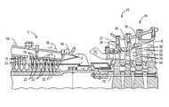
- FIG. 1is a cross sectional view of an exemplary combustion turbine.
- FIG. 2is a perspective view of an exemplary combustion turbine vane.
- FIG. 3is a side view of the vane of FIG. 2 .
- FIG. 4is an exemplary heat flux sensor deposited on a substrate.
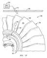
- FIG. 5is a perspective view of an exemplary turbine blade, sensor and wireless telemetry device.
- FIG. 6is a schematic of an exemplary wireless telemetry device.
- FIG. 7is a partial perspective view of an exemplary compressor blade.
- FIG. 8is a partial side view of the exemplary compressor blade of FIG. 7 .
- FIG. 9is a partial cross sectional view of the exemplary turbine blade of FIG. 5 .
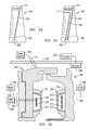
- FIG. 10is a perspective view of the exemplary turbine blade of FIG. 9 , an exploded view of a telemetry transmitter housing and an exemplary rotating antenna assembly mounted to the turbine blade.
- FIG. 11is an exploded view of an exemplary embodiment of the telemetry transmitter housing of FIG. 10 .
- FIG. 12illustrates components of an exemplary rotating antenna assembly.
- FIG. 13is a partial perspective view on a turbine static seal having an exemplary embodiment of a stationary antenna assembly mounted thereto.
- FIG. 14is a partial cross sectional view of the turbine static seal of FIG. 12 and a turbine blade assembly having an exemplary rotating power and antenna assembly mounted thereto.
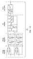
- FIG. 15is a block diagram of an exemplary telemetry transmitter circuit.
- FIG. 16is a schematic of an exemplary induction power driver circuit.
- FIG. 17is a partial perspective view of a blisk having thereon wireless telemetry components including a sensor and a telemetry device.
- FIG. 18is a schematic illustration of a telemetry device linked to a sensor.
- FIG. 19is a schematic illustration of circuits for a resonant energy transfer system.
- FIG. 20is a schematic representation of a rotating data antenna.
- FIG. 21is a sectional schematic illustration of a telemetry device on a rotor of a blisk including a rotating data antenna on the blisk and a stationary antenna on a stator.
- FIG. 22illustrates a transmitter device housed within an RF transparent cover.
- FIG. 23is an embodiment of the wireless telemetry system wherein an energy receiving coil is on a blade for a blisk.
- FIG. 24is an embodiment of the wireless telemetry system wherein an energy receiving coil and the rotating data antenna are on a blade for a blisk.
- FIG. 25is an embodiment of the wireless telemetry system wherein a stationary telemetry circuit and stationary antenna are used to transmit data relating to stationary components and rotating components.
- FIG. 1illustrates an exemplary combustion turbine 10 such as a gas turbine used for generating electricity. Embodiments of the invention may be used with combustion turbine 10 or in numerous other operating environments and for various purposes.
- Combustion turbine 10includes a compressor 12 , at least one combustor 14 (broken away) and a turbine 16 .
- Compressor 12 , combustor 14 and turbine 16are sometimes referred to collectively as a gas or combustion turbine engine 10 .
- Turbine 16includes a plurality of rotating blades 18 , secured to a rotatable central shaft 20 .
- a plurality of stationary vanes 22are positioned between blades 18 , with vanes 22 being dimensioned and configured to guide air over blades 18 .
- Blades 18 and vanes 22will typically be made from nickel-based alloys, and may be coated with a thermal barrier coating (“TBC”) 26 , such as yttria-stabilized zirconia.
- TBCthermal barrier coating
- compressor 12includes a plurality of rotating blades 19 positioned between respective vanes 23 .
- Combustor 14mixes the air with fuel and ignites it thereby forming a working gas.
- This working gas temperaturewill typically be above about 1300° C.
- This gasexpands through turbine 16 , being guided across blades 18 by vanes 22 .
- As the gas passes through turbine 16it rotates blades 18 and shaft 20 , thereby transmitting usable mechanical work through shaft 20 .
- Combustion turbine 10may also include a cooling system (not shown), dimensioned and configured to supply a coolant, for example, steam or compressed air, to blades 18 and vanes 22 .
- Embodiments of the inventionare advantageous because components may transmit real time or near real time data indicative of a component's condition during operation of combustion turbine 10 .
- U.S. Pat. No. 6,576,861discloses a method and apparatus that may be used to deposit embodiments of sensors and connectors for connecting sensors with transmitters or otherwise routing data signals.
- methods and apparatus disclosed thereinmay be used for the patterning of fine sensor and/or connector features of between about 100 microns and 500 microns without the need of using masks.
- Multilayer electrical circuits and sensorsmay be formed by depositing features using conductive materials, resistive materials, dielectric materials, insulative materials and other application specific materials. Alternate methods may be used to deposit multilayer electrical circuits, sensors and connectors such as thermal spraying, vapor deposition, laser sintering and curing deposits of material sprayed at lower temperatures may be used as well as other suitable techniques.
- FIG. 2illustrates a pair of adjacent vanes 23 removed from compressor 12 with one vane 23 having a sensor 50 mounted or connected thereto for detecting a condition of the vane.
- a lead line or connector 52may be deposited as a means for routing a data signal from sensor 50 to a transmitter 54 configured for wirelessly transmitting the data signal to a transceiver 56 .
- Connector 52may be one or a plurality of electrical leads for conducting a signal from sensor 50 to transmitter 54 . Alternate embodiments allow for various types of connectors 52 to be used as a means for routing a data signal from sensor 50 to transmitter 54 , depending on the specific application.
- Transmitters 54may be multi-channel and have various specifications depending on their location within a casing of combustion turbine 10 . Transmitters 54 may be configured to function within the early stages of compressor 12 , which are subject to operating temperatures of between about 80° C. to 120° C. Transmitters 54 may be configured to function within later stages of compressor 12 and/or stages of turbine 16 subject to operating temperatures of greater than about 120° C. and up to about 300° C. Transmitters 54 may be fabricated using silicon-on-insulator (SOI) technology and other materials capable of operating in regions with temperatures greater than about 120° C.
- SOIsilicon-on-insulator
- FIG. 3illustrates a schematic plan view of compressor vane 23 having sensor 50 connected therewith and connector 52 connecting sensor 50 with transmitter 54 .
- a power source 51may be provided, such as an appropriately sized battery for powering transmitter 54 .
- Transmitter 54may receive signals from sensor 50 via connector 52 that are subsequently wirelessly transmitted to transceiver 56 .
- Transceiver 56may be mounted on hub 58 or on a surface external to compressor 12 such as the exemplary locations shown in FIG. 1 .
- Transceiver 56may be mounted in various locations provided it is within sufficient proximity to transmitter 54 to receive a wireless data transmission, such as an RF signal from transmitter 54 .
- One or more sensors 50may be connected with one or more compressor vanes 23 by fabricating or depositing sensors 50 and connectors 52 directly onto a surface of vane 23 .
- Connector 52may extend from sensor 50 to a termination location, such as the peripheral edge of vane 23 so that a distal end 53 of connector 52 is exposed for connection to transmitter 54 .
- Sensor 50 and connector 52may be positioned on vane 23 to minimize any adverse affect on the aerodynamics of vane 23 .
- Embodimentsallow for a distal end 53 of connectors 52 to be exposed at a termination location, which may be proximate a peripheral edge of a component or other suitable location. This allows a field technician to quickly and easily connect connector 52 to a transmitter 54 regardless of its location.
- FIG. 4illustrates an exemplary sensor 61 that may be deposited within a barrier coating such as TBC 60 , which may be yttria-stabilized zirconia.
- TBC 60may be deposited on a bond coat 62 , which may be deposited on a substrate 64 .
- Substrate 64may be various components such as a superalloy suitable for use in turbine 16 such as a turbine blade 18 .
- Sensor 61may be formed for various purposes and may include thermocouples 66 deposited using conventional K, N, S, B and R-type thermocouple material, or any combination of their respective constituent elements provided that the combination generates an acceptable thermoelectric voltage for a particular application within combustion turbine 10 .
- Type K thermocouple materials NiCr or NiAlmay be used in sections of compressor 12 having an operating environment up to approximately 800° C.
- NiCr(20)may be used to deposit a strain gage in compressor 12 .
- Type N thermocouple materialsuch as alloys of NiCrSi and NiSi, for example, may be used for depositing sensors in sections of turbine 16 having an operating environment between approximately 800° C. to 1150° C.
- Type S, B and R thermocouple materialsmay be used for depositing sensors in sections of turbine 16 having an operating environment between approximately 1150° C. to 1350° C.
- Pt—Rh, Pt—Rh(10) and Pt—Rh(13)may be deposited to form sensors 50 within turbine 16 provided that the material generates an acceptable thermoelectric voltage for a particular application within combustion turbine 10 .
- Ni alloysfor example, NiCr, NiCrSi, NiSi and other oxidation-resistant Ni-based alloys such as MCrAlX, where M may be Fe, Ni or Co, and X may be Y, Ta, Si, Hf, Ti, and combinations thereof, may be used as sensing materials for high temperature applications in deeper sections of compressor 12 and throughout turbine 16 .
- These alloysmay be used as sensing material deposited in various sensing configurations to form sensors such as heat flux sensors, strain sensors and wear sensors.
- FIG. 5shows an exemplary turbine blade 70 , which may be a blade from row 1 of turbine 16 , having high temperature resistant lead wires, such as connectors 72 deposited to connect an embedded or surface mounted sensor 74 with a wireless telemetry device 76 .
- Device 76may be mounted in a location where the telemetry components are exposed to relatively lower temperatures, such as proximate the root 78 of blade 70 where the operating temperature is typically about 150° C.-250° C. and higher.
- Silicon-based electronic semiconductorssuch as those that may be used for transmitting data, may have limited applications due to their operational temperature constraints. Temperature and performance properties of silicon and silicon-on-insulator (SOI) electronic chip technologies may limit their applications to operating environments of less than about 200° C. Aspects of the invention allow for such electronic systems to be deployed for wireless telemetry device 76 within compressor 12 , which typically has an operating temperature of about 100° C.-150° C.
- Embodiments of wireless telemetry sensor systemsmay be configured to operate within higher temperature regions present in later stages of compressor 12 , and within turbine 16 . These regions may have operating temperatures of about 150° C.-250° C. and higher. Materials having temperature and electrical properties capable of operation in these higher temperature regions may be used for depositing sensors 50 , 74 , connectors 52 , 72 and fabricating wireless telemetry devices 76 .
- Sensors 50 , 74 and high temperature interconnect lines or connectors 52 , 72may be deposited using known deposition processes such as plasma spraying, EB PVD, CVD, pulsed laser deposition, mini-plasma, direct-write, mini-HVOF or solution plasma spraying.
- plasma sprayingEB PVD, CVD, pulsed laser deposition
- mini-plasmamini-plasma
- direct-writemini-HVOF or solution plasma spraying.
- dynamic pressure measurements, dynamic and static strain, and dynamic acceleration measurementsare desired on both stationary and rotating components of combustion turbine 10 together with component surface temperature and heat flux measurements.
- embedded or surface mounted sensors 50 , 74may be configured as strain gages, thermocouples, heat-flux sensors, pressure transducers, micro-accelerometers as well as other desired sensors.
- FIG. 6is a schematic of a representative embodiment of a wireless telemetry device 76 .
- Device 76may be formed as a circuit board or integrated chip that includes a plurality of electronic components such as resistors, capacitors, inductors, transistors, transducers, modulators, oscillators, transmitters, amplifiers, and diodes either embossed, surface mounted or otherwise deposited thereon with or without an integral antenna and/or power source.
- Embodiments of wireless telemetry device 76may be fabricated for use in compressor 12 and/or turbine 16 .
- Wireless telemetry device 76may include a board 80 , an electronic circuit 90 , an operational amplifier 92 , a modulator 94 and an RF oscillator/transmitter 96 electrically connected with each other via interconnects 98 .
- the embodiment of FIG. 6is an exemplary embodiment and other embodiments of device 76 are contemplated depending on performance specifications and operating environments.
- Embodiments of device 76allow for a power source 100 , and a transmitting and receiving antenna 102 to be fabricated on board 80 thereby forming a transmitter such as transmitter 54 shown in FIGS. 2 and 3 , or wireless telemetry device 76 , shown in FIG. 5 .
- FIG. 7illustrates a partial perspective view of an exemplary blade, such as a blade 110 having a blade root 112 , which may be a compressor blade within compressor 12 .
- One or more recesses or trenches 114may be formed within root 112 such as within the bottom of blade root 112 .
- Recesses 114may be formed in various shapes or dimensions and located within blade root 112 at various places along its length.
- One or more recesses or trenches 116may be formed in one or more faces 118 of blade root 112 .
- Recesses 116may be formed in various shapes or dimensions and located within blade root 112 at various places within a face 118 .
- Recesses 114 , 116may be formed using various methods such as by milling them out after blade 110 is cast or by forming them as part of the blade 110 mold.
- FIG. 8illustrates compressor blade 110 instrumented with components of wireless telemetry device 76 affixed within blade root 112 .
- alternate embodiments of wireless telemetry device 76allow for one or more electrical components 90 , 92 , 94 , 96 , 100 , 102 , shown in FIG. 6 , to be mounted separately or contained on discrete boards 80 that are electrically connected and affixed with an instrumented component such as blade root 112 .
- a transmitting and receiving antenna 102 shown in FIG. 6may be mounted separately from and electrically connected with board 80 having a transmitter 122 formed thereon and being electrically connected with antenna 102 .
- Antenna 120may be seated within recess 116 and transmitter 122 may be seated within recess 114 .
- antenna 120 and transmitter 122are not mounted/embossed or deposited onto a board 80 .
- antenna 120may be deposited on a wireless telemetry board 80 , as shown in FIG. 6 , and the data may be transmitted using wireless telemetry to a receiver such as a stationary mounted transceiver 56 .
- Power source 100may be integral with board 80 or located separately from the board and mounted as a discrete component.
- FIG. 9illustrates a partial view of an exemplary blade 130 , which may be a turbine blade such as one of the turbine blades 18 .
- Turbine blade 130includes a root portion 132 defining an outer mold line for mating with a rotor disk of turbine 16 within which blade 130 may be secured for operation of combustion turbine 10 .
- Sensing materialmay be deposited on blade 130 or within a barrier coating deposited on the blade's surface to form a sensor 134 .
- Connecting materialmay be deposited to form connectors 140 so that data signals from sensor 134 may be communicated to a transmitter 138 and subsequently to a rotating antenna assembly 142 .
- a recess 136may be formed within a portion of blade 130 so that one or more connectors 140 are seated below an outer surface of blade 130 .
- Transmitter 138 and antenna assembly 142may be integrally secured with blade 130 so that the outer mold line defined by root 132 is not altered.
- transmitter 138may be affixed to a transition area, or platform, above the fir tree portion of root 132 and antenna assembly 142 may be affixed to a face of root 132 .
- recessesmay be formed within the platform and face so that all or a portion of transmitter 138 and/or antenna assembly 142 are seated below the surface of the outer mold line of blade root 172 .
- Transmitter 138 and antenna assembly 142may be secured within respective recesses using an epoxy or adhesive and a backfill material may be placed over them for protection from high temperatures or particulates.
- wireless telemetry device 76may be affixed to blade root 78 externally or embedded in such a way so that an outer mold line of the blade root is not significantly altered.
- Device 76may be affixed proximate blade root 78 so that it is contained within a cavity that is created between the blade root 78 and a rotor disk of turbine 16 when blade root 78 is inserted within the rotor disk. This enables a turbine blade 70 instrumented with sensor 74 , connectors 72 and device 76 to be installed into a mating segment of a rotor disk of turbine 16 in the same manner as a turbine blade that is not instrumented.
- instrumented blade 70may be manufactured having all components necessary for wirelessly extracting data indicative of various operating parameters or conditions of blade 70 and/or a barrier coating deposited thereon and transmitting that data to a receiving device.
- one or more recesses or trenchesmay be formed into a portion of the substrate of blade 70 , such as blade root 78 , within which one or more wireless telemetry devices 76 may be contained.
- Trenchesmay be formed by milling out desired regions of blade root 78 and securing device 76 within the trench with an epoxy or other suitable binder.
- the trenchesmay be back filled with a suitably high temperature cement or ceramic paste to protect device 76 .
- Embodiments of the present inventionallow for transmitting sensor data from a rotating component, such as a turbine engine blade 130 having certain electronic components located on root 132 of the blade, which operates in an environment having a temperature of between about 300° C.-500° C.
- a rotating componentsuch as a turbine engine blade 130 having certain electronic components located on root 132 of the blade
- the term “high temperature” without additional qualificationwill refer to any operating environment, such as that within portions of combustion turbine 10 , having a maximum operating temperature of between about 300° C.-500° C.
- Embodiments of the present inventionprovide components for use in combustion turbine 10 instrumented with telemetry systems that may include one or more sensors, lead lines connecting sensors with at least one telemetry transmitter circuit, at least one transmitting antenna, a power source and at least one receiving antenna.
- FIG. 10illustrates turbine blade 130 , a wireless telemetry transmitter assembly 150 and rotating antenna assembly 142 .
- Lead lines or connectors 152may extend from one or more sensors, such as sensors 70 , 134 to telemetry transmitter assembly 150 when mounted proximate blade root 132 .
- Lead lines 152may route electronic data signals from sensor 70 , 134 to telemetry transmitter assembly 150 where the signals are processed by a telemetry transmitter circuit formed on a circuit board contained within an electronics package 154 shown in FIG. 11 .
- Lead lines or connectors 140may be deposited for routing electronic data signals from a telemetry transmitter circuit to rotating antenna assembly 142 .
- FIG. 11illustrates a high temperature electronics package 154 that may contain a high temperature circuit board and form part of telemetry transmitter assembly 150 .
- the main body of electronics package 154may be fabricated from alloys such as Kovar, an alloy of Fe—Ni—Co.
- the thermal expansion coefficient of Kovarranges from about 4.5 ⁇ 6.5 ⁇ 10 ⁇ 6 /° C., depending on exact composition.
- the Ni-based alloys typically used for high temperature turbine components, such as turbine blade 130have thermal expansion coefficients in the range of about 15.9 ⁇ 16.4 ⁇ 10 ⁇ 6 /° C.
- Electronics package 154may be affixed securely in place while allowing for relative movement between electronics package 154 and turbine blade 130 . This relative movement may result from their different thermal expansion rates, which occur over time during the high number of thermal cycles between ambient air temperature and the >450° C. operating temperature typically experienced proximate blade root 132 .
- the telemetry transmitter assembly 150may include a mounting bracket 156 and a lid or cover plate 158 with electronics package 154 positioned therebetween.
- a plurality of connecting pins 155enable connection between an electronic circuit board contained within package 154 , such as one having a wireless telemetry circuit fabricated thereon, and various external devices such as lead lines from sensors, induction coil assemblies and/or data transmission antennae.
- Mounting bracket 156 , cover plate 158 and retention screws 159 connecting them togethermay all be fabricated from the same material as is turbine blade 130 . This ensures there is no difference in thermal expansion between turbine blade 130 and mounting bracket 156 . Consequently, no stresses are generated in mounting bracket 156 and/or turbine blade 130 during thermal transients.
- the thermal expansion coefficient of electronics package 154may be less than that of mounting bracket 156 when the operating system within which these components reside is at a high temperature. Consequently, electronics package 154 , including any circuit board contained therein, would expand less than mounting bracket 156 , which may lead to damage caused by vibrational energy in the system.
- a layer of ceramic fiber woven fabric 160may be placed between the electronic package 154 and the inside surface of mounting bracket 156 .
- Fabric 160may be fabricated from suitable ceramic fiber, including such fibers as silicon carbide, silicon nitride or aluminum oxide. For example, a quantity of NextelTM aluminum oxide based fabric, manufactured by 3M, may be used for fabric 160 .
- mounting bracket 156may be attached to turbine blade 130 by a suitable means for attaching such as bolting, welding, brazing or via transient liquid phase bonding.
- FIG. 10illustrates a recess or flat pocket 162 that may be milled or otherwise formed within turbine blade 130 proximate blade root 132 for receiving assembly 150 .
- Cover plate 158may be formed with a flange 164 oriented perpendicular to the direction of G-forces, to add structural support to the cover plate, which counters the G-load forces occurring when rotating turbine blade 130 is operating at full speed. This relieves retention screws 159 from carry the load applied to cover plate 158 via G-forces, and allows them to be made sufficiently small so that the telemetry transmitter assembly 150 fits in the relatively small recess 162 with no interference with any adjacent components. If retention screws 159 were required to carry the load applied by the G-forces, their required size would be too large to fit in the available space.
- FIG. 10shows that rotating antenna assembly 142 may be affixed to the end face or neck of root 132 .
- Assembly 142may be an electronic assembly having thermal expansion coefficients different than those of the Ni-based alloys used for turbine hot gas path components such as turbine blade 130 including its root 132 .
- One or more rotating antenna assemblies 142may be protected from windage during rotation of turbine blade 130 at near the speed of sound.
- the windage protection materialis transparent to RF radiation frequencies in order to enable transmission of power and data through the material.
- Embodiments of rotatable antenna assembly 142may include a durable, protective, RF transparent cover 170 shown in FIGS. 10 and 12 , which is essentially a hollow fixture within which a data antenna and induction power components are contained.
- RF transparent cover 170protects its contents from windage and hot gas ingress during operation of combustion turbine 10 .
- Certain ceramicsare suitable for protecting RF transmission equipment from the elements at elevated temperatures. However, many ceramics and ceramic matrix composites are prone to chipping and cracking under the vibrational, impact and G-loading that a rotating turbine blade 130 experiences during operation of combustion turbine 10 .
- RF transparent cover 170may be fabricated from an RF transparent, high toughness, structural ceramic materials. Ceramic matrix composites may be used to fabricate housing 170 as well as material selected from a family of materials known as toughened ceramics. Materials such as silicon carbide, silicon nitride, zirconia and alumina are available with increased toughness due to doping with additional elements and/or designed microstructures resulting from specific processing approaches.
- ZTAzirconia-toughened alumina
- RF transparent cover 170is designed so that the tensile stresses in the ceramic material are minimized during operation of combustion turbine 10 . This is accomplished by designing and fabricating such that (1) all corners, edges and bends of the ZTA components are machined to eliminate sharp corners and edges, in order to reduce the stress concentration factor at these locations, and (2) the orientation and fit of the ZTA component in a rotating antennae mounting bracket 174 is such that during operation the G-forces applied to the ZTA box do not generate significant bending stresses in the attachment flanges. This is accomplished by orienting the flanges parallel with the G-loading direction, rather than perpendicular to the G-loading direction, so the ZTA flange is loaded in compression and not in bending.
- FIG. 12illustrates that a rotating antennae mounting bracket 174 may be assembled with RF transparent cover 170 to form rotating antenna assembly 142 , as shown affixed to turbine blade 130 in FIG. 10 .
- the interface loading between the rotating antennae mounting bracket 174 and the RF transparent cover 170minimizes the tensile stresses that occur in RF transparent cover 170 .
- the designis such that the tensile stresses that occur in the RF transparent cover 170 are less than the minimum stress for fracture, resulting in long life for the structural component.
- Mounting bracket 174may be made of the same metal as turbine blade 130 because the uniform thermal expansion coefficient between them will result in minimal stresses being generated in the attachment region during heat-up and cool-down cycles.
- Mounting bracket 174may be designed so that all the G-loading experienced by rotating antenna assembly 142 during operation of combustion turbine 10 is absorbed in a direction extending toward upper end 178 of bracket 174 , as indicated by arrow G in FIG. 12 . No portion of mounting bracket 174 extends far enough past an antenna contained therein to attenuate the RF transmission data signal.
- RF transparent cover 170is secured in place so its internal stress field is primarily compressive and may be retained using threaded pins (not shown) through semicircular divots on its flanges.
- Mounting bracket 174may be attached to a face of turbine blade root 132 via conventional means such as welding, brazing, bonding, bolting or screwing.
- An embodiment of rotating antenna assembly 142may be assembled by placing desired antennae into the hollow body of RF transparent cover 170 , feeding lead wires 171 from the antennae out through holes formed within cover 170 and then filling the hollow body of cover 170 containing the antennae with a ceramic potting material. The potted RF transparent cover 170 containing the antennae may then be slid into mounting bracket 174 , which may have been previously affixed to turbine blade root 132 . Cover 170 may be secured to mounting bracket 174 via pins inserted in holes in mounting bracket 174 and divots in cover 170 .
- Embodiments of the present inventionmay be powered by various means such as induced RF energy and/or by harvesting thermal or vibrational power within the combustion turbine engine 16 .
- thermoelectric or vibro-electric powercould be generated from the energy available in an operating combustion turbine engine 16 .
- Thermopilesmay be used to generate electricity from thermal energy, or piezoelectric materials may generate electricity from vibration of combustion turbine engine 16 . Examples of these forms of power sources are described in the patent application having application Ser. No. 11/516,338 filed Sep. 6, 2006, the entire disclosure of which is incorporated herein by reference.
- Embodiments of the present inventionprovide induced power modes for powering components of wireless high temperature telemetry systems.
- Such systemsmay be configured as air-gap transformers where the transformer primary induction coil assembly 186 is stationary and the secondary induction coil assembly 195 rotates.
- an induced RF power configurationis provided for powering a rotating telemetry transmitter contained within telemetry transmitter assembly 150 .
- FIG. 13illustrates a portion of a static seal segment 180 such as one that may be used within the turbine engine 16 of combustion turbine 10 .
- a plurality of static seal segments 180may encircle turbine engine 16 adjacent to a plurality of turbine blades 130 .
- Static seal segments 180may cooperate with turbine blades 130 for sealing hot gas within a hot gas path through turbine engine 16 as recognized by those skilled in the art.
- FIG. 13shows an arcuate bracket 182 having respective channels or grooves formed therein within which a stationary data transmission antenna 184 and a stationary primary induction coil assembly 186 may be secured.
- Data transmission antenna 184may be inserted into a non-conducting holder 185 for securing data transmission antenna 184 with bracket 182 .
- Non-conducting holder 185ensures that data transmission antenna 184 does not contact bracket 182 , which may be fabricated of metal, thereby ensuring correct operation.
- Non-conducting holder 185may be fabricated from the same ZTA toughened ceramic material used for the RF transparent cover 170 .
- holder 185may be segmented to provide flexibility, which allows for installation in curved bracket 182 . The same segmented configuration may be applied to the induction coil assembly 186 to enable installation in a curved bracket 182 .
- Primary induction coil assembly 186 and data transmission antenna holder 185may be formed with lobes in the region of attachment to bracket 182 .
- the associated regions of material in the bracket 182are removed in the same lobe shape, with slightly larger size to accommodate installation.
- the lobe shapedefines a radius of curvature that enables positive retention of induction coil assembly 186 and antenna and holder 184 , 185 , which may be placed into bracket 182 from an end and slid into position.
- the lobe shapeenables positive retention to be maintained while simultaneously ensuring that tensile stresses are not generated in induction coil assembly 186 and antenna holder 185 , both of which may be fabricated of relatively brittle materials subject to structural failure under tensile stresses.
- the lobesmay be positioned far enough from the front of induction coil assembly 186 and data transmission antenna 184 to ensure that metal bracket 182 does not interfere with functionality.
- Ceramic cementmay be applied between the surfaces of induction coil assembly 186 and antenna holder 185 , and their respective pockets in bracket 182 , in order to provide a secure fit and accommodate thermal expansion differences during heat up and cool down.
- a thin plate(not shown) may be attached on each end of bracket 182 that covers the lobed regions of the induction coil assembly 186 and the data antenna 184 , ensuring retention during operation.
- Bracket 182may be fabricated of the same alloy as static seal segment 180 , such as Inconel 625 , and have an arcuate shape to conform to the interior surface of static seal segment 180 . Bracket 182 may be affixed to the interior surface of static seal segment 180 using an interrupted weld 188 to minimize distortion of static seal segment 180 .
- Induction coil assembly 186may include at least one stationary core 190 and at least one stationary primary winding 192 with ‘H Cement’ 194 sold by JP Technologies encasing portions of stationary core 190 .
- FIG. 14illustrates an embodiment having a rotating secondary induction coil assembly 195 contained within RF transparent cover 170 , which may be mounted proximate turbine engine blade root 132 .
- the rotating induction coil assembly 195may be fabricated from a core 200 and winding 201 , similar to the stationary induction coil assembly 186 .
- a rotating data transmission antenna 202may be provided for communication with stationary data transmission antenna 184 .
- Data transmission antenna 202may be encased within a non-conducting holder 203 , which may be similar in construction as non-conducting holder 185 .
- data transmission antenna 202may be contained in RF transparent cover 170 , without use of non-conducting holder 203 , in which case it may be held in place with a high temperature capable potting material.
- Single or multiple stationary primary induction coils 186may be arranged on the interior surface of one or more static seal segments 180 to form an arc that is circumscribed by rotating secondary induction coil assembly 195 and antenna 202 when combustion turbine 10 is in operation.
- One or more stationary primary winding 192may be energized by high frequency, high current power sources.
- the powercan be supplied to each stationary induction coil assembly 186 individually, or a series of stationary induction coil assemblies 186 may be electrically connected and driven by a single power supply. In an exemplary embodiment there may be five adjacent, stationary induction coil assemblies 186 with each driven by its own power supply.
- the current flowing through each stationary primary winding 192creates a magnetic field in the rotating secondary induction coil assembly 195 that in turn creates a current in the rotating secondary winding 201 .
- the current from rotating secondary winding 201supplies power to a wireless telemetry transmitter circuit contained within wireless telemetry transmitter assembly 150 as described more fully herein below.
- FIG. 14illustrates that an initial gap “A” may exist between RF transparent cover 170 and stationary core 190 prior to startup of combustion turbine 10 .
- Initial gap “A”may be about 13 mm at startup of combustion turbine 10 and reduce to about 4 mm at baseload when turbine blade 130 and static seal segment 180 are closer together.
- Magnetic core materialsmay be used to fabricate stationary core 190 and rotating core 200 .
- a magnetic materialmay be used as a core material in order to couple the required power to a telemetry transmitter circuit contained within telemetry transmitter assembly 150 over the required gap “A”.
- the selected magnetic materialacts to focus the magnetic field produced by the stationary primary windings 192 and received by one or more rotating secondary windings 201 . This effect increases the coupling efficiency between the stationary and rotating elements.
- Embodiments of induced power systems disclosed hereinmay employ multiple individual primary and secondary induction coil assemblies 186 , 195 to accommodate various geometries with combustion turbine 10 .
- stationary induction coil assembly 186 and data transmission primary antenna 184may need to span a certain distance of static seal segment 180 in order to induce enough power to the system components and transmit the required data.
- An embodiment of induction coil assembly 186 and data transmission antenna 184may need to be approximately four feet in length.
- four individual power/antenna assemblies each with a length of approximately one footmay be fabricated with respective brackets 182 and installed adjacent to one another on one or more static seal segments 180 .
- antenna assemblywill function as if it were a single, four-foot long antenna.
- Such antenna assembliesmay be formed from straight or curved elements thereby providing assemblies of varying lengths that are straight, curved or otherwise configured as required by the specific application.
- a plurality of such antenna assembliesmay span an arc of approximately 112 degrees in the top half of one or more static seal segments 180 within turbine 16 .
- the inventors of the present inventionhave determined that a particular class of magnetic core materials meets or exceeds the performance requirements of embodiments of the present invention.
- the general term for this class of materialsis a nanocrystalline iron alloy.
- One composition of this class of materialis sold under the trade name NAMGLASS® and has a composition of approximately 82% iron—with the balance being silicon, niobium, boron, copper, carbon, nickel and molybdenum. It has been determined that such nanocrystalline iron alloy material exhibits desirable characteristics such as a Curie temperature greater than 500° C., very low coercivity, low eddy-current loss, high saturation flux density and the permeability is very stable over the entire high temperature operating range.
- This nanocrystalline iron alloy materialis commercially available in tape-wound configurations in the form of toroids, or “C” core transformer cores.
- Embodiments of the present inventionutilize this nanocrystalline iron alloy material to form an “I” core shape, which was used for the primary stationary core 190 .
- the “I” shapewas selected because this shape holds itself in place in the channel on stationary mounting bracket 182 .
- the induction core 190 of each induction coil assembly 186consists of a plurality of 0.007′′ thick laminations of nanocrystalline iron alloy material built up into an arc of approximately eleven inches in length. The same nanocrystalline iron alloy material may be used for the rotating antenna 200 transformer core.
- the strength of the magnetic field used to couple power between the stationary and rotating elementsmay be increased by increasing the frequency of the driving signal, i.e. the high frequency AC signal produced by an exemplary induction power driver circuit illustrated in FIG. 16 .
- the driving signali.e. the high frequency AC signal produced by an exemplary induction power driver circuit illustrated in FIG. 16 .
- embodiments of the present inventionmay employ a high frequency to drive the stationary primary windings 192 , such as frequencies greater than approximately 200 kHz. Alternate embodiments may achieve an operating frequency of at least one megahertz with a power driver designed to operate at such frequencies.
- the wire used for winding cores 190 , 200may be made of a 27% nickel-clad copper with ceramic insulation in order to reduce oxidation and failure at high temperatures.
- the handling characteristics of this wireare significantly more challenging than standard organic-insulated bare copper, as a result of the protective, ceramic coating, and special techniques were developed for the processes of winding both the primary and rotating elements.
- Other wiresmay be insulated silver or anodized aluminum.
- Two types of ceramic materialsmay be used in the construction of both the primary and rotating induction coil assemblies 186 , 195 . It is important to ensure the windings 192 , 201 do not short (conduct) to the core elements 190 , 200 .
- a compoundsuch as H cement, a ceramic cement with ultra fine particle size, may be used as an insulating base coat on the winding cores 190 , 200 .
- the winding cores 190 , 200may be potted with Cotronics 940 , an aluminum oxide based ceramic cement.
- the voltage regulator of transmitter circuit 210maintains a constant DC voltage output, even though the AC input voltage may vary. A constant voltage output is required to achieve better accuracy and stable operating frequency for the signal output.
- the voltage regulatoralso supplies a constant voltage a strain gauge sensor 134 and a ballast resistor (not shown).
- the strain gauge sensor 134 and ballast resistorprovide the sensor signal input to the transmitter circuit 210 . As the surface where the strain gauge sensor 134 is mounted deflects, the strain gauge changes resistance, which causes the voltage at the transmitter circuit 210 input to change.
- the varying voltage provided by the signal from the strain gauge sensor 134is amplified first by a differential amplifier and then by a high gain AC amplifier.
- the resulting signalis applied to a varactor diode in the voltage controlled oscillator (VCO) section of transmitter circuit 210 .
- the VCOoscillates at a high carrier frequency. This carrier frequency may be set in the band of 125 to 155 MHz with respect to transmitter circuit 210 .
- the fixed carrier frequencyis changed slightly by the changing voltage on the varactor. This change in frequency or deviation is directly related to the deflection or strain undergone by strain gauge sensor 134 .
- the VCO carrier outputis fed to a buffer stage and the buffer output connects to a transmitting antenna contained in the rotating antenna assembly 142 via lead wires 140 of FIG. 10 .
- a receiving devicesuch as transceiver 56 in FIG. 1 or other devices located in high temperature or other areas within combustion turbine 10
- the carrier signalis removed and the deviation becomes the amplified output that is proportional to strain.
- the transistors used in such a transmitter circuit 210 designed for high temperature usemay be fabricated from a high temperature capable material, such as wide band gap semiconductor materials including SiC, AlN, GaN, AlGaN, GaAs, GaP, InP, AlGaAs, AlGaP, AlInGaP, and GaAsAlN, or other high temperature capable transistor material may be used up to about 500-600° C.
- wireless telemetry transmitter circuit 210fabricated on a circuit board may be adapted for use within combustion turbine 10 at varying operating temperatures and with a range of sensor types.
- Elements of transmitter circuit 210 and alternate embodiments thereofmay be fabricated using various temperature sensitive materials such as silicon-on-insulator (SOI) integrated circuits up to approximately 350° C.; polysilseqioxane, PFA, polyimide, Nomex, PBZT, PBO, PBI, and Voltex wound capacitors from approximately 300-350° C.; and PLZT, NPO, Ta 2 O 5 , BaTiO 3 multilayer ceramic capacitors from approximately 450-500° C.
- SOIsilicon-on-insulator
- resistorsmay be fabricated of Ta, TaN, Ti, SnO 2 , Ni—Cr, Cr—Si and Pd—Ag for operating environments of approximately up to 350° C. and Ru, RuO 2 , Ru—Ag and Si 3 N 4 for operating environments of approximately 350° C. and greater.
- Individual high temperature electronic componentssuch as discrete transistor, diode or capacitor die made from SiC, AlN, GaN, AlGaN, GaAs, GaP, InP, AlGaAs, AlGaP, AlInGaP, and GaAsAIN, or other high temperature capable semiconducting material, may be replaced by a single SOI CMOS device for operation at temperatures not exceeding approximately 350° C.
- the antenna 102which may be a transceiver to receive and/or transmit electrical signals, is fabricated on the same board as a telemetry transmitter circuit.
- the telemetry transmitter circuitmay include the electronic circuit 90 , a multivibrator circuit (not shown), an operational amplifier 92 , an RF modulator 94 and an RF oscillator/transmitter 96 electrically connected with each other via interconnects 98 .
- the device 76may include the power source 110 in electrical communication with the electrical circuit 90 and antenna 102 .
- the above-described electrical components 90 , 92 , 94 and 96are formed on a board or substrate 80 in the form of a circuit board or an integrated chip.
- the power source 110may be mounted off the substrate proximate a blade or vane, or both the antenna 102 and power source are off the board but remain in electrical communication with the telemetry transmitter circuit.
- FIG. 6 and the embodiments shown in FIGS. 17-23may employ a resonant energy transfer assembly in which magnetic cores with windings are eliminated.
- These embodimentsmay be especially advantageous for use with smaller modular combustion turbine engines that are used in aeronautics. More specifically, such modular turbine systems for example incorporate a blisk that includes blades 301 integrally formed with a rotor disc 302 that are significantly smaller than for example compressor or turbine blade stages used in power generation plants. Accordingly, the blisk may not have sufficient surface area available for supporting the power induction coil assemblies 186 and 195 including the magnetic cores 190 and 200 shown in FIG. 14 .
- FIG. 17Components of the wireless telemetry system are shown in FIG. 17 with respect to a blisk 300 which includes a plurality of blades 301 integrally formed with a rotor disc 302 .
- each blade 301includes a foil portion 303 over which hot expanding gas flows causing the blisk 300 to rotate in the case of a turbine.
- the rotation of a compressor bliskdraws ambient temperature gas from outside the turbine past the rotating blades, compressing the gas as it is directed through the later compressor stages, and to the turbine stage of a turbine engine.
- Each blade 301 or foil portion 303has a tip 304 adjacent and in spaced relation to a casing 305 within which rotating components such as the blades 301 and stationary components such as vanes (not shown) are positioned.
- the blisk 300may be positioned for operation in a power turbine or compressor for a turbine engine.
- the below-described resonant energy transfer assemblymay be used in connection with the monitoring of rotating components such as blades 301 or stationary components such as vanes.
- An embedded or surface mounted sensor 306is disposed on the blade 301 relative to an area for which operating conditions of the blade 301 are monitored. Temperature resistant lead lines or connectors 307 electrically link the sensor 306 with a wireless telemetry device 308 .
- the device 308is preferably mounted in a location where telemetry components are exposed to relatively lower temperatures such as the rotor 309 of the blisk 300 where the operating temperature is typically about 150° C. to about 250° C.
- the sensor 306 and interconnect lines 307may be deposited using known deposition processes such as plasma spraying, EB PVD, CVD, pulsed laser deposition, mini-plasma, direct-write, mini-HVOF or solution plasma spraying.
- plasma sprayingEB PVD, CVD, pulsed laser deposition
- mini-plasmamini-plasma
- direct-writemini-HVOF or solution plasma spraying
- embedded or surface mounted sensor 306may be configured as strain gages, thermocouples, heat-flux sensors, pressure transducers, micro-accelerometers as well as other desired sensors.
- the materials used to fabricate the sensormay include those thermocouple materials listed and described relative to the sensor 61 shown in FIG. 4 for both the compressor or turbine components.
- the embodiment of the wireless telemetry system shown in FIGS. 17-25includes a resonant energy transfer system having a primary coil or probe 310 mounted at a stationary location, within the compressor 12 or turbine 10 , relative to the rotating components of assembly including wireless telemetry device 308 and sensor 306 .
- the primary coil 310may be mounted to a casing 313 of the compressor or turbine and is linked to an RF power source 315 .
- the telemetry device 308includes a telemetry circuit 312 , such as that described relative to FIG. 15 , and a power source in the form secondary coil 311 .
- the transmitter device 308includes RF data antenna 314 that is in electrical communication with the telemetry transmitter circuit 312 .
- coilas used herein in reference to the primary coil and the below-described secondary coil is not necessarily an indication of a physical configuration of such a component. Indeed, one or both of the “coils” may be in the form of a probe.
- coilis intended to include a power transmitting and power receiving device that include the appropriately configured electrical components such as capacitors and inductors to generate an oscillating current from the primary device and induces power in the secondary device which is tuned to resonate that the same frequency as that of the oscillating current.
- the primary coil 310receiving power from the RF power source 315 , generates an oscillating electromagnetic radiation signal field, and energy is transferred to the secondary coil 311 which powers the telemetry transmitter circuit 312 .
- the sensor 306generates electronic data signals, indicative of an operating condition of a component such as blades 301 , and the electronic data signals are sent to the telemetry transmitter circuit 312 , which routes the electronic data signals to the data antenna 314 .
- the electronic data signalsare indicative of an operating condition of the component, such as the blade 301 .
- the device 308may be fabricated as a circuit board or as an integrated chip in which both the antenna 314 and the secondary coil 311 are deposited on a substrate with circuit 312 .
- FIG. 19An exemplary circuit for the primary coils 310 and secondary coil 311 for the transfer of energy is shown in FIG. 19 and includes primary coil 310 includes a transmitting coil or inductor L 1 linked to a source coil or inductor L 3 via an air core transformer. Similarly, the secondary coil includes a receiving coil or inductor L 2 linked to a source coil L 4 via an air core transformer.
- the transmitting coil L 1has a resistance Rc and a resonating capacitor C; and, the receiving coil L 2 also includes a coil resistance Rc and a resonating capacitor C.
- a source resistance Rs at the source coil L 3 and the load resistance RL at the load coil L 4do not contribute to the Q of the resonant system, thereby increasing the coupling between the primary coil 310 and the secondary coil 311 and therefore the distance that power can be transmitted.
- the respective RLC circuits for the primary coil 310 and secondary coil 311are tuned so that the coils 310 and 311 are resonant at the same or common frequency so that power may be transmitted from the primary coil 310 to the secondary coil 311 .
- the coils 310 and 311may be composed of temperature and oxidative resistant materials such as Ni, a Ni-based superalloy, Incanel®, gold, platinum or other materials that are operative at temperatures of about 250° C. or higher.
- an RF power drivermay serve as the power source to the primary coil so that coils are resonant at a common frequency between the Hz and GHz range, with an exemplary embodiment being one MHz to about 15 MHz, and preferably at about 10 MHz.
- the antenna 314is printed on the circuit board, and a desired length of the can be calculated as follows:
- cthe speed of light in free space
- fthe frequency of carrier signal
- ⁇ rthe dielectric constant of the substrate.
- an antenna length of 478 mmwhich is far beyond an allowable size for a circuit board. Accordingly, an antenna trace may be provided in a folded back and forth configuration.
- a layout of an exemplary monopole antennais shown in FIG. 20 .
- the secondary coil 311should be sufficiently separated from the telemetry circuit 312 except for a connecting signal path to avoid interference between the RF modulator and multivibrator circuit of the telemetry transmitter circuit 312 .
- FIG. 21illustrates a sectional view of a blisk 300 and stator 323 with an embodiment of the invention having a telemetry transmitter assembly 316 contained within an RF transparent cover 317 , which may be mounted proximate the rotor disc 302 of blisk 300 using bracket 318 .
- the assembly 316includes a telemetry circuit 312 , secondary coil 311 and data antenna 314 fabricated in on the same substrate as an integrated chip.
- connectors 319are provided to electrically connect the lead lines 307 and sensor 306 to the telemetry transmitter circuit 312 .
- telemetry transmitter circuit 312 , secondary coil 311 and antenna 314may secured within the RF transparent cover 317 with a high temperature capable non-conducting, high dielectric potting material.
- the rotating data antenna 314may be provided for communication with stationary data antenna 320 , which is inserted into a non-conducting holder 321 for securing data transmission antenna 320 with bracket 322 .
- the bracket 322is mounted to a stationary component as the stator 323 , or a static seal segment associated with the stator 323 .
- Non-conducting holder 321ensures that stationary data transmission antenna 320 does not contact bracket 322 , which may be fabricated of metal, thereby ensuring correct operation.
- Non-conducting holder 322may be fabricated from the same ZTA toughened ceramic or Yttria-stabilized zirconia (YSZ), alumina, or other high temperature ceramic material used for the RF transparent cover 317 .
- YSZYttria-stabilized zirconia
- holder 322may be segmented to provide flexibility, which allows for installation in a curved bracket.
- the stationary antenna 320may extend circumferentially on the stator 323 so that electronic data signals may be received from the rotating data antenna 314 at any point or time during operation of the turbine engine.
- an electrical lead wire 340electrically connects the stationary antenna 320 to a controller or processor 341 so that the electronic data signal received from the rotating data 314 are transmitted for processing to monitor the operating conditions of the blade 301 .
- the secondary coil 311may be deposited on the tip 304 of the foil portion 303 of blade 301 .
- an electrical lead line 324is also deposited on the blade 301 electrically connecting the coil 311 to the telemetry circuit 312 affixed to the rotor disc 302 in the manner described above.
- the rotating data antenna 314may be fabricated on the circuit board 80 with the telemetry circuit 312 , which eliminates the need for an antenna block in the area where the board 80 is located. This reduces the area required for locating the wireless telemetry system in the root section of a blade or blisk.
- both the secondary coil 311 and the rotating data antenna 314are deposited on the foil portion 303 of the blade 301 .
- the electrical lead line 324electrically connects the coil 311 to the telemetry transmitter circuit 312 thereby powering the circuit 312 .
- the electrical lead line 325routes electrical data signals from the transmitter circuit 312 to the rotating data antenna 314 .
- an RF transparent coveris not required.
- the telemetry circuit 312may be housed in an electronics package as shown in FIG. 11 , and mounted to the rotor disc 302 .
- FIG. 25there is illustrated an embodiment of a wireless telemetry system including a resonant energy transfer system that includes two telemetry transmitter devices 330 and 331 , each of which includes a telemetry transmitter circuit. More specifically, the system includes a first or rotating transmitter device 330 and a second or stationary transmitter device 331 .
- FIG. 25is a sectional view of a rotating component such as the above-described blisk 300 of a turbine or compressor, which may also represent a turbine blade stage of larger compressors and turbines.
- the blisk 300is positioned adjacent a stationary component such as a stator 323 .
- the first (or rotating) telemetry device 330may include a telemetry transmitter circuit 312 , a data antenna 314 and a secondary coil 311 fabricated as an integrated chip. Alternatively, either one or both of the data antenna 314 and/or secondary coil 311 are on the blade 301 or airfoil 303 . In addition, one or more sensors 306 are disposed on a portion of the blade 301 that is intended to be monitored during operation of the compressor 12 or turbine 10 . Electrical lead lines 307 connect the sensors 306 to the telemetry transmitter circuit 312 in order to route electric data signals, indicative of an operating condition of the blade 306 , to the telemetry transmitter circuit 312 . The transmitter circuit 312 is electrically connected to the first antenna 314 to route the electric data signals to the antenna 314 .
- the telemetry systemincludes a primary coil 310 that is linked to an RF power source 315 , supplies a current or power to the primary coil 310 .
- the primary coil 310is positioned at a stationary location relative to blisk 300 , such as a turbine or compressor casing 305 .
- blisk 300such as a turbine or compressor casing 305 .
- the primary coil 310receiving power from the RF power source 315 , generates an oscillating electromagnetic radiation signal field, and energy is transferred to the secondary coil 311 which powers the telemetry transmitter circuit 312 .
- the telemetry device 330includes an RF transparent cover 314 and bracket 318 to affix the circuit 312 to the rotor disc 302 of the blisk 300 .
- An RF transparent coveris not required if the antenna 314 is disposed on the blade 301 or some other location on the blisk 300 and off the substrate of the telemetry transmitter circuit 312 .
- the wireless telemetry systemalso includes a mechanism for acquiring and transmitting electronic data signals indicative of a condition of a stationary component within the turbine 10 or compressor 12 .
- a second or stationary telemetry device 331is affixed to the stator 323 .
- the second telemetry device 331includes a telemetry circuit 332 and antenna 333 (also referred to as a stationary antenna or second antenna), that are fabricated on a substrate in the form of an integrated chip; however, the antenna 333 may be affixed to the stator apart from telemetry circuit 333 as shown in FIG. 22 .
- one or more sensors 335are positioned at stationary locations in the compressor 12 or turbine 10 , to monitor conditions of the stator 323 or other stationary components.
- Electrical lead lines 334electrically connect the sensors 335 to the second or stationary telemetry circuit 332 to transmit electronic data signals indicative of the condition of a stationary component to the second telemetry circuit 332 .
- the telemetry circuit 332is in electrical communication with the second or stationary antenna 333 to route the signals to the antenna 333 .
- the stationary antenna 333may be fabricated on the same substrate as that of the telemetry circuit 332 , or may be separately mounted as shown in FIG. 21 .
- the RF transparent cover 317is not required for the second telemetry circuit 332 or antenna, as operating conditions such as windage and centrifugal loading may not be as extreme relative to the blade 301 and disc 302 .
- a power source 336is linked to the second telemetry circuit 332 via an electrical lead line 337 .
- This electrical connectionmay be necessary in order to provide sufficient power to the telemetry circuit 332 to route signals from the sensors 335 to the antenna 333 and further transmit the electronic data signals from the second or stationary antenna 333 to a receiver 338 .
- the receiver 338is mounted at a stationary location proximate the second antenna 333 and is linked to a controller or processor 339 for processing the electronic signals that are indicative of operating conditions of stationary and rotating components.
- the antenna 333is configured to transmit electronic data signals received from the stationary sensors 335 and telemetry circuit 332 as well as electronic data signals transmitted from the rotating antenna 314 .
- the electronic data signalsmay be transmitted from the stationary antenna 333 either wirelessly or via an electronic lead wire (not shown). In this manner, the stationary antenna 333 receives and transmits electronic data signals relative operating conditions of both stationary and rotating components of a turbine 10 or compressor 12 .
Landscapes
- Engineering & Computer Science (AREA)
- Mechanical Engineering (AREA)
- General Engineering & Computer Science (AREA)
- Power Engineering (AREA)
- Computer Networks & Wireless Communication (AREA)
- Chemical & Material Sciences (AREA)
- Combustion & Propulsion (AREA)
- Physics & Mathematics (AREA)
- General Physics & Mathematics (AREA)
- Arrangements For Transmission Of Measured Signals (AREA)
- Selective Calling Equipment (AREA)
Abstract
Description
wherein c is the speed of light in free space, f is the frequency of carrier signal and ∈ris the dielectric constant of the substrate. For example in connection with a LTCC (low temperature co-fired ceramic) substrate the f=80 MHz and ∈r=6.7, an antenna length of 478 mm, which is far beyond an allowable size for a circuit board. Accordingly, an antenna trace may be provided in a folded back and forth configuration. A layout of an exemplary monopole antenna is shown in
Claims (18)
Priority Applications (6)
| Application Number | Priority Date | Filing Date | Title |
|---|---|---|---|
| US13/015,782US9071888B2 (en) | 2007-11-08 | 2011-01-28 | Instrumented component for wireless telemetry |
| CN2011800079785ACN102792711A (en) | 2010-02-01 | 2011-01-31 | Instrumented component for wireless telemetry |
| EP11706974.0AEP2532174B1 (en) | 2010-02-01 | 2011-01-31 | Instrumented component for wireless telemetry |
| PCT/US2011/023165WO2011094682A1 (en) | 2010-02-01 | 2011-01-31 | Instrumented component for wireless telemetry |
| KR1020127022951AKR101493253B1 (en) | 2010-02-01 | 2011-01-31 | Instrumented component for wireless telemetry |
| JP2012551367AJP5662480B2 (en) | 2010-02-01 | 2011-01-31 | Instrumentation components for wireless telemetry |
Applications Claiming Priority (4)
| Application Number | Priority Date | Filing Date | Title |
|---|---|---|---|
| US11/936,936US8519866B2 (en) | 2007-11-08 | 2007-11-08 | Wireless telemetry for instrumented component |
| US30018410P | 2010-02-01 | 2010-02-01 | |
| US30018810P | 2010-02-01 | 2010-02-01 | |
| US13/015,782US9071888B2 (en) | 2007-11-08 | 2011-01-28 | Instrumented component for wireless telemetry |
Related Parent Applications (1)
| Application Number | Title | Priority Date | Filing Date |
|---|---|---|---|
| US11/936,936Continuation-In-PartUS8519866B2 (en) | 2007-11-08 | 2007-11-08 | Wireless telemetry for instrumented component |
Publications (2)
| Publication Number | Publication Date |
|---|---|
| US20110133950A1 US20110133950A1 (en) | 2011-06-09 |
| US9071888B2true US9071888B2 (en) | 2015-06-30 |
Family
ID=44319848
Family Applications (1)
| Application Number | Title | Priority Date | Filing Date |
|---|---|---|---|
| US13/015,782Expired - Fee RelatedUS9071888B2 (en) | 2007-11-08 | 2011-01-28 | Instrumented component for wireless telemetry |
Country Status (6)
| Country | Link |
|---|---|
| US (1) | US9071888B2 (en) |
| EP (1) | EP2532174B1 (en) |
| JP (1) | JP5662480B2 (en) |
| KR (1) | KR101493253B1 (en) |
| CN (1) | CN102792711A (en) |
| WO (1) | WO2011094682A1 (en) |
Cited By (10)
| Publication number | Priority date | Publication date | Assignee | Title |
|---|---|---|---|---|
| US9320181B1 (en)* | 2014-11-14 | 2016-04-19 | General Electric Company | System and method for dissipating thermal energy away from electronic components in a rotatable shaft |
| US20160209264A1 (en)* | 2015-01-16 | 2016-07-21 | General Electric Company | Passive wireless sensors for turbmomachines and method of operating the same |
| US20170342910A1 (en)* | 2016-05-25 | 2017-11-30 | General Electric Company | Attachment system for a gas turbine engine |
| US10408091B2 (en) | 2017-03-31 | 2019-09-10 | General Electric Company | Mounting apparatuses secured to turbine airfoils of turbine systems |
| US10663280B2 (en) | 2018-03-23 | 2020-05-26 | General Electric Company | System and method for measuring eccentricity of gas turbine casing relative to rotor |
| US10920605B2 (en) | 2017-12-21 | 2021-02-16 | General Electric Company | System and method for measuring eccentricity of turbine shell relative to turbine rotor |
| US11371383B2 (en)* | 2018-07-31 | 2022-06-28 | Safran Aircraft Engines | System for inspecting components of a turbojet engine using radio-frequency identification |
| US20230396099A1 (en)* | 2022-06-03 | 2023-12-07 | Deere & Company | Assembly for contactless transfer of electrical energy to a rotor |
| US11885228B2 (en) | 2022-02-09 | 2024-01-30 | General Electric Company | System and method for inspecting fan blade tip clearance relative to an abradable fan case |
| US20240271561A1 (en)* | 2023-02-13 | 2024-08-15 | Raytheon Technologies Corporation | Gas turbine engine component with integrated sensor bracket |
Families Citing this family (27)
| Publication number | Priority date | Publication date | Assignee | Title |
|---|---|---|---|---|
| US9134186B2 (en)* | 2011-02-03 | 2015-09-15 | Kla-Tencor Corporation | Process condition measuring device (PCMD) and method for measuring process conditions in a workpiece processing tool configured to process production workpieces |
| DE102011110666A1 (en)* | 2011-05-11 | 2012-11-15 | Micro-Epsilon Messtechnik Gmbh & Co. Kg | Sensor, system with a sensor and a measurement object and method for temperature measurement by means of a sensor |
| US9746388B2 (en)* | 2011-06-29 | 2017-08-29 | Honeywell International Inc. | Wireless telemetry using voltage and pulse intervals |
| ITTO20110578A1 (en)* | 2011-06-30 | 2012-12-31 | Ansaldo Energia Spa | GAS TURBINE ROTOR ASSEMBLY AND TELEMETRY SYSTEM AND METHOD FOR DETECTION OF MEASUREMENTS ON A GAS TURBINE ROTOR VIA TELEMETRY |
| US9129742B2 (en)* | 2011-07-06 | 2015-09-08 | Siemens Energy, Inc. | Gas turbine engine comprising an ultra high temperature circuit coupling open core transformer |
| EP2565605A1 (en)* | 2011-08-29 | 2013-03-06 | Siemens Aktiengesellschaft | Flow engine with a temperature sensor in a part of the rotor |
| US9097122B2 (en)* | 2012-01-30 | 2015-08-04 | United Technologies Corporation | Turbine engine monitoring system |
| RU2494849C1 (en)* | 2012-04-18 | 2013-10-10 | Открытое акционерное общество "Научно-производственное объединение "Сатурн" | Method of producing of distributor |
| KR101328520B1 (en)* | 2012-05-17 | 2013-11-20 | 한양대학교 산학협력단 | Plasma apparatus |
| FR2996875A1 (en)* | 2012-10-12 | 2014-04-18 | Snecma | INSTALLATION OF MEASUREMENTS FOR BREAKING TESTS ON A TURBOMACHINE |
| US9420356B2 (en) | 2013-08-27 | 2016-08-16 | Siemens Energy, Inc. | Wireless power-receiving assembly for a telemetry system in a high-temperature environment of a combustion turbine engine |
| EP3039433B1 (en) | 2013-08-29 | 2018-01-10 | Jaquet Technology Group AG | Sensor device for determining rotational speed of a rotatable object and turbocharger with such a sensor device |
| US9511855B2 (en)* | 2014-01-22 | 2016-12-06 | Sikorsky Aircraft Corporation | Power and data transfer to hub sensors |
| WO2015130563A1 (en) | 2014-02-28 | 2015-09-03 | United Technologies Corporation | Protected wireless network |
| US9194250B1 (en)* | 2014-05-07 | 2015-11-24 | General Electric Company | Embedded wireless sensors for turbomachine component defect monitoring |
| US10378994B2 (en)* | 2015-03-05 | 2019-08-13 | Ai Alpine Us Bidco Inc. | Wireless vibration monitoring of movable engine parts |
| US10107132B2 (en)* | 2015-05-05 | 2018-10-23 | United Technologies Corporation | Embedded sensor system |
| CN108431372A (en)* | 2015-12-30 | 2018-08-21 | 西门子股份公司 | Gas turbine, seal cover, seal telemetry assembly and method of manufacture |
| FI128674B (en)* | 2016-02-04 | 2020-10-15 | Rolls Royce Oy Ab | Apparatus for transferring electrical energy |
| US9972896B2 (en) | 2016-06-23 | 2018-05-15 | General Electric Company | Wireless aircraft engine monitoring system |
| KR101999432B1 (en)* | 2017-04-04 | 2019-07-11 | 두산중공업 주식회사 | System and Method for Magnetic Field to Flutter Measurement of A Turbine Blade |
| WO2019100082A1 (en)* | 2017-11-20 | 2019-05-23 | Sensatek Propulsion Technology, Inc. | Apparatus, systems, and methods for wireless monitoring of gas turbine engine temperature |
| CN113939956A (en)* | 2019-06-12 | 2022-01-14 | 3M创新有限公司 | Transparent Antenna Stacks and Components |
| FR3098848B1 (en)* | 2019-07-16 | 2021-06-18 | Safran Aircraft Engines | Turbomachine fan blade comprising an identification medium and method of reading such an identification medium |
| US11686208B2 (en) | 2020-02-06 | 2023-06-27 | Rolls-Royce Corporation | Abrasive coating for high-temperature mechanical systems |
| JP2023011278A (en) | 2021-07-12 | 2023-01-24 | トヨタ自動車株式会社 | Antennas, telemetry devices and telemetry measurement systems |
| CN116380295B (en)* | 2023-06-05 | 2023-09-01 | 中国航发四川燃气涡轮研究院 | Wiring method for high-temperature strain gauge of middle-stage blisk blade of air compressor |
Citations (92)
| Publication number | Priority date | Publication date | Assignee | Title |
|---|---|---|---|---|
| US3876998A (en) | 1972-09-28 | 1975-04-08 | Siemens Ag | Arrangement for the inductive transmission of signals between a stationary point and a rotating electric machine part |
| US3890456A (en) | 1973-08-06 | 1975-06-17 | United Aircraft Corp | Process of coating a gas turbine engine alloy substrate |
| US4339719A (en) | 1980-07-30 | 1982-07-13 | Electric Power Research Institute, Inc. | Conductivity sensor for monitoring corrodents being deposited in a steam turbine |
| US4446461A (en) | 1981-11-02 | 1984-05-01 | United Technologies Corporation | Instrumentation for a rotary machine |
| US4546652A (en) | 1981-12-22 | 1985-10-15 | Materials Research, Inc. | In-situ on-line structural failure detection system, its preparation and operation |
| US4578992A (en) | 1982-11-05 | 1986-04-01 | Philip E. Galasko | Detection of a low pressure condition of a vehicle tire |
| US4595298A (en) | 1985-05-01 | 1986-06-17 | The United States Of America As Represented By The Secretary Of The Air Force | Temperature detection system for use on film cooled turbine airfoils |
| US4703326A (en) | 1985-01-24 | 1987-10-27 | Mtu Motoren-Und Turbinen-Union Munchen Gmbh | Method and apparatus for measuring pressures in a rotor of a turbomachine |
| US4812050A (en) | 1985-05-28 | 1989-03-14 | The United States Of America As Represented By The Secretary Of The Navy | Method for calibrating a heat flux gauge |
| US4851300A (en) | 1988-05-09 | 1989-07-25 | United Technologies Corporation | Precoat for improving platinum thin film adhesion |
| US4860442A (en) | 1988-11-28 | 1989-08-29 | Kulite Semiconductor | Methods for mounting components on convoluted three-dimensional structures |
| US4916715A (en) | 1988-04-13 | 1990-04-10 | General Electric Company | Method and apparatus for measuring the distribution of heat flux and heat transfer coefficients on the surface of a cooled component used in a high temperature environment |
| US4969956A (en) | 1989-12-19 | 1990-11-13 | The United States Of America As Represented By The Secretary Of Commerce | Transparent thin film thermocouple |
| US4970670A (en) | 1988-11-30 | 1990-11-13 | Westinghouse Electric Corp. | Temperature compensated eddy current sensor temperature measurement in turbine blade shroud monitor |
| US4983034A (en) | 1987-12-10 | 1991-01-08 | Simmonds Precision Products, Inc. | Composite integrity monitoring |
| US5005353A (en) | 1986-04-28 | 1991-04-09 | Rolls-Royce Plc | Active control of unsteady motion phenomena in turbomachinery |
| US5144299A (en)* | 1990-05-29 | 1992-09-01 | United Technologies Corporation | Telemetry power carrier pulse encoder |
| US5197337A (en)* | 1991-04-03 | 1993-03-30 | Ametek | Low force flowmeter pick-off |
| US5268006A (en)* | 1989-03-15 | 1993-12-07 | Matsushita Electric Industrial Co., Ltd. | Ceramic capacitor with a grain boundary-insulated structure |
| US5306368A (en) | 1992-01-17 | 1994-04-26 | Ngk Insulators, Ltd. | Formation of ceramic thin film on ceramic body |
| US5318725A (en) | 1991-04-03 | 1994-06-07 | American Superconductor Corporation | Electroceramics and process for making the same |
| US5350279A (en)* | 1993-07-02 | 1994-09-27 | General Electric Company | Gas turbine engine blade retainer sub-assembly |
| US5416430A (en) | 1993-04-28 | 1995-05-16 | Electric Power Research Institute, Inc. | Apparatus and method for identification and location of internal arcing in dynamoelectric machines |
| US5440300A (en) | 1992-11-25 | 1995-08-08 | Simmonds Precision Products, Inc. | Smart structure with non-contact power and data interface |
| US5578877A (en) | 1994-06-13 | 1996-11-26 | General Electric Company | Apparatus for converting vibratory motion to electrical energy |
| US5952836A (en) | 1997-04-28 | 1999-09-14 | Mcdonnell Douglas Corporation | Device and method for detecting workpiece fractures |
| US5956073A (en)* | 1996-12-19 | 1999-09-21 | Lucent Technologies Inc. | Noise-limiting transformer apparatus and method for making |
| US5970393A (en) | 1997-02-25 | 1999-10-19 | Polytechnic University | Integrated micro-strip antenna apparatus and a system utilizing the same for wireless communications for sensing and actuation purposes |
| US5969260A (en) | 1998-03-30 | 1999-10-19 | Mcdonnell Douglas Corporation | Remotely interrogatable apparatus and method for detecting defects in structural members |
| US6000977A (en) | 1997-09-04 | 1999-12-14 | Mcdonnell Douglas Corporation | Electrical connection devices for composite structures having externally accessible ports |
| US6034296A (en) | 1997-03-11 | 2000-03-07 | Elvin; Niell | Implantable bone strain telemetry sensing system and method |
| US6072165A (en) | 1999-07-01 | 2000-06-06 | Thermo-Stone Usa, Llc | Thin film metal/metal oxide thermocouple |
| US6109783A (en) | 1997-08-21 | 2000-08-29 | Abb Research Ltd. | Optic pyrometer for gas turbines |
| US6127040A (en) | 1996-08-26 | 2000-10-03 | Siemens Matsushita Components Gmbh & Co. Kg | Electroceramic component and method of manufacture thereof |
| US6142665A (en) | 1996-07-18 | 2000-11-07 | Abb Alstom Power Ltd | Temperature sensor arrangement in combination with a gas turbine combustion chamber |
| US6197424B1 (en) | 1998-03-27 | 2001-03-06 | Siemens Westinghouse Power Corporation | Use of high temperature insulation for ceramic matrix composites in gas turbines |
| US6262550B1 (en) | 1999-12-17 | 2001-07-17 | General Electric Company | Electrical motor monitoring system and method |
| US6280083B2 (en) | 1998-01-12 | 2001-08-28 | Isuzu Ceramics Research Institute Co., Ltd. | Thermocouple lance with layered sheath for measuring temperature in molten metal |
| US6331823B1 (en) | 1995-11-06 | 2001-12-18 | Reliance Electric Technologies, Llc | Monitoring system for bearings |
| US6343251B1 (en) | 2000-10-20 | 2002-01-29 | General Electric Company | Method and system for monitoring the operation of and predicting part life consumption for turbomachinery |
| US6398503B1 (en) | 1998-04-27 | 2002-06-04 | Kabushiki Kaisha Toshiba | High temperature component, gas turbine high temperature component and manufacturing method thereof |
| US20020068488A1 (en)* | 2000-08-28 | 2002-06-06 | Boston Microsystems, Inc. | Stable electrical contact for silicon carbide devices |
| US20020083712A1 (en) | 2000-12-28 | 2002-07-04 | Tomlinson Leroy Omar | Control system and method for gas turbine inlet-air water-saturation and supersaturation system |
| US6437681B1 (en) | 1999-10-27 | 2002-08-20 | Cyntec Company | Structure and fabrication process for an improved high temperature sensor |
| US20020143477A1 (en) | 2001-02-19 | 2002-10-03 | Marc Antoine | Determination of a degradation of a gas turbine |
| US6512379B2 (en) | 2001-02-05 | 2003-01-28 | Siemens Westinghouse Power Corporation | Condition monitoring of turbine blades and vanes in service |
| US20030020480A1 (en) | 2001-07-25 | 2003-01-30 | Maylotte Donald Herbert | Wireless sensor assembly for circumferential monitoring of gas stream properties |
| US6523383B2 (en) | 2000-12-28 | 2003-02-25 | The Timken Company | Monitoring and controlling system with connectorless quick-change components |
| US20030038628A1 (en)* | 2001-08-27 | 2003-02-27 | Nath Shridhar Champaknath | Self reference eddy current probe, measurement system, and measurement method |
| US6532412B2 (en) | 2000-11-02 | 2003-03-11 | General Electric Co. | Apparatus for monitoring gas turbine engine operation |
| US20030049119A1 (en) | 2001-03-21 | 2003-03-13 | Johnson Neldon P. | Pressurized gas turbine engine |
| US6556956B1 (en) | 2000-06-30 | 2003-04-29 | General Electric Company | Data acquisition unit for remote monitoring system and method for remote monitoring |
| US6576861B2 (en) | 2000-07-25 | 2003-06-10 | The Research Foundation Of State University Of New York | Method and apparatus for fine feature spray deposition |
| US6591182B1 (en) | 2000-02-29 | 2003-07-08 | General Electric Company | Decision making process and manual for diagnostic trend analysis |
| US20030202876A1 (en)* | 2002-04-26 | 2003-10-30 | Christophe Jasklowski | Attachment of a ceramic shroud in a metal housing |
| US6667725B1 (en) | 2002-08-20 | 2003-12-23 | The United States Of America As Represented By The Administrator Of The National Aeronautics And Space Administration | Radio frequency telemetry system for sensors and actuators |
| US6677683B2 (en) | 2001-01-18 | 2004-01-13 | Eads Deutschland Gmbh | System for supplying power to ROSAR transponders, including transmitting and receiving antennas for ROSAR devices |
| US6729187B1 (en) | 1999-04-29 | 2004-05-04 | The Board Of Governors For Higher Education, State Of Rhode Island And Providence Plantations | Self-compensated ceramic strain gage for use at high temperatures |
| US6735549B2 (en) | 2001-03-28 | 2004-05-11 | Westinghouse Electric Co. Llc | Predictive maintenance display system |
| US20040101022A1 (en)* | 2002-11-22 | 2004-05-27 | General Electric Company | Systems and methods for determining conditions of articles and methods of making such systems |
| US20040114666A1 (en) | 2002-12-17 | 2004-06-17 | Hardwicke Canan Uslu | Temperature sensing structure, method of making the structure, gas turbine engine and method of controlling temperature |
| US6756908B2 (en) | 2001-12-28 | 2004-06-29 | United Technologies Corporation | Crack detection in fracture-critical machine parts |
| US6756131B2 (en) | 2001-12-17 | 2004-06-29 | Mitsubishi Heavy Industries, Ltd. | High temperature corrosion resistant alloy, thermal barrier coating material, and gas turbine using high temperature corrosion resistant alloy |
| US6760689B2 (en) | 2002-01-04 | 2004-07-06 | General Electric Co. | System and method for processing data obtained from turbine operations |
| US6796187B2 (en) | 2000-12-08 | 2004-09-28 | The Johns Hopkins University | Wireless multi-functional sensor platform, system containing same and method for its use |
| US6808813B2 (en) | 2000-07-14 | 2004-10-26 | Matsushita Electric Industrial Co., Ltd. | Ceramic electronic device and method of manufacturing the device |
| US6816817B1 (en) | 2000-09-28 | 2004-11-09 | Rockwell Automation Technologies, Inc. | Networked control system with real time monitoring |
| US6831555B1 (en) | 2002-03-05 | 2004-12-14 | Advanced Micro Devices, Inc. | Method and apparatus for dynamically monitoring system components in an advanced process control (APC) framework |
| US6838157B2 (en) | 2002-09-23 | 2005-01-04 | Siemens Westinghouse Power Corporation | Method and apparatus for instrumenting a gas turbine component having a barrier coating |
| US20050061058A1 (en) | 2003-09-24 | 2005-03-24 | Siemens Aktiengesellschaft | Method and apparatus of monitoring temperature and strain by using fiber bragg grating (FBG) sensors |
| US20050162164A1 (en)* | 2002-05-30 | 2005-07-28 | Keemilise Ja Bioogilise Fuusika Instituut | Probehead for nmr spectometer |
| US20050198967A1 (en) | 2002-09-23 | 2005-09-15 | Siemens Westinghouse Power Corp. | Smart component for use in an operating environment |
| US6979991B2 (en) | 2003-04-16 | 2005-12-27 | United Technologies, Corporation | Nondestructive, electrical impedance-based, thermal barrier coating inspection |
| US6979498B2 (en) | 2003-11-25 | 2005-12-27 | General Electric Company | Strengthened bond coats for thermal barrier coatings |
| US20050287386A1 (en)* | 2002-09-23 | 2005-12-29 | Siemens Westinghouse Power Corporation | Method of instrumenting a component |
| US20060020415A1 (en) | 2004-07-23 | 2006-01-26 | Hardwicke Canan U | Sensor and method for making same |
| US20060018361A1 (en) | 2004-07-23 | 2006-01-26 | Hardwicke Canan U | Sensor and method for making same |
| US7009310B2 (en) | 2004-01-12 | 2006-03-07 | Rockwell Scientific Licensing, Llc | Autonomous power source |
| DE102005040794A1 (en)* | 2004-09-09 | 2006-04-06 | Alstom Technology Ltd | Telemetry system for transferring data between stationary and rotating components of gas turbine, comprises transmitters arranged on moving component for transferring data to receiver arranged on the stationary component |
| US7208230B2 (en)* | 2003-08-29 | 2007-04-24 | General Electric Company | Optical reflector for reducing radiation heat transfer to hot engine parts |
| US7247004B2 (en)* | 2002-03-27 | 2007-07-24 | Hitachi, Ltd. | Electronically controlled actuator |
| JP2007278283A (en) | 2006-04-04 | 2007-10-25 | United Technol Corp <Utc> | Sensor assembly for gas turbine engine |
| US20080063514A1 (en)* | 2006-09-11 | 2008-03-13 | Eric Durocher | Seal system for an interturbine duct within a gas turbine engine |
| US7368827B2 (en) | 2006-09-06 | 2008-05-06 | Siemens Power Generation, Inc. | Electrical assembly for monitoring conditions in a combustion turbine operating environment |
| WO2008091289A2 (en) | 2006-09-14 | 2008-07-31 | Siemens Energy, Inc. | Instrumented component for use in an operating environment |
| US7423518B2 (en) | 2005-03-25 | 2008-09-09 | Seiko Epson Corporation | Reader/writer |
| US20090115627A1 (en) | 2007-11-06 | 2009-05-07 | Honeywell International Inc. | Moving and stationary body system using telemetry |
| US20090121896A1 (en) | 2007-11-08 | 2009-05-14 | Siemens Power Generation, Inc. | Instrumented Component for Wireless Telemetry |
| WO2010039319A2 (en) | 2008-08-15 | 2010-04-08 | Siemens Energy, Inc. | A wireless telemetry electronic circuit package for high temperature environments |
| US7712663B2 (en) | 2005-07-04 | 2010-05-11 | Sony Corporation | Communication board |
| US7908014B2 (en)* | 2006-05-05 | 2011-03-15 | Alfred E. Mann Foundation For Scientific Research | Antenna on ceramic case |
| US8011255B2 (en)* | 2003-03-05 | 2011-09-06 | Microstrain, Inc. | Shaft mounted energy harvesting for wireless sensor operation and data transmission |
Family Cites Families (1)
| Publication number | Priority date | Publication date | Assignee | Title |
|---|---|---|---|---|
| US6792187B2 (en)* | 2002-12-17 | 2004-09-14 | Corning Incorporated | Ca-Al-Si oxide glasses and optical components containing the same |
- 2011
- 2011-01-28USUS13/015,782patent/US9071888B2/ennot_activeExpired - Fee Related
- 2011-01-31WOPCT/US2011/023165patent/WO2011094682A1/enactiveApplication Filing
- 2011-01-31KRKR1020127022951Apatent/KR101493253B1/ennot_activeExpired - Fee Related
- 2011-01-31JPJP2012551367Apatent/JP5662480B2/ennot_activeExpired - Fee Related
- 2011-01-31CNCN2011800079785Apatent/CN102792711A/enactivePending
- 2011-01-31EPEP11706974.0Apatent/EP2532174B1/ennot_activeNot-in-force
Patent Citations (95)
| Publication number | Priority date | Publication date | Assignee | Title |
|---|---|---|---|---|
| US3876998A (en) | 1972-09-28 | 1975-04-08 | Siemens Ag | Arrangement for the inductive transmission of signals between a stationary point and a rotating electric machine part |
| US3890456A (en) | 1973-08-06 | 1975-06-17 | United Aircraft Corp | Process of coating a gas turbine engine alloy substrate |
| US4339719A (en) | 1980-07-30 | 1982-07-13 | Electric Power Research Institute, Inc. | Conductivity sensor for monitoring corrodents being deposited in a steam turbine |
| US4446461A (en) | 1981-11-02 | 1984-05-01 | United Technologies Corporation | Instrumentation for a rotary machine |
| US4546652A (en) | 1981-12-22 | 1985-10-15 | Materials Research, Inc. | In-situ on-line structural failure detection system, its preparation and operation |
| US4578992A (en) | 1982-11-05 | 1986-04-01 | Philip E. Galasko | Detection of a low pressure condition of a vehicle tire |
| US4703326A (en) | 1985-01-24 | 1987-10-27 | Mtu Motoren-Und Turbinen-Union Munchen Gmbh | Method and apparatus for measuring pressures in a rotor of a turbomachine |
| US4595298A (en) | 1985-05-01 | 1986-06-17 | The United States Of America As Represented By The Secretary Of The Air Force | Temperature detection system for use on film cooled turbine airfoils |
| US4812050A (en) | 1985-05-28 | 1989-03-14 | The United States Of America As Represented By The Secretary Of The Navy | Method for calibrating a heat flux gauge |
| US5005353A (en) | 1986-04-28 | 1991-04-09 | Rolls-Royce Plc | Active control of unsteady motion phenomena in turbomachinery |
| US4983034A (en) | 1987-12-10 | 1991-01-08 | Simmonds Precision Products, Inc. | Composite integrity monitoring |
| US4916715A (en) | 1988-04-13 | 1990-04-10 | General Electric Company | Method and apparatus for measuring the distribution of heat flux and heat transfer coefficients on the surface of a cooled component used in a high temperature environment |
| US4851300A (en) | 1988-05-09 | 1989-07-25 | United Technologies Corporation | Precoat for improving platinum thin film adhesion |
| US4860442A (en) | 1988-11-28 | 1989-08-29 | Kulite Semiconductor | Methods for mounting components on convoluted three-dimensional structures |
| US4970670A (en) | 1988-11-30 | 1990-11-13 | Westinghouse Electric Corp. | Temperature compensated eddy current sensor temperature measurement in turbine blade shroud monitor |
| US5268006A (en)* | 1989-03-15 | 1993-12-07 | Matsushita Electric Industrial Co., Ltd. | Ceramic capacitor with a grain boundary-insulated structure |
| US4969956A (en) | 1989-12-19 | 1990-11-13 | The United States Of America As Represented By The Secretary Of Commerce | Transparent thin film thermocouple |
| US5144299A (en)* | 1990-05-29 | 1992-09-01 | United Technologies Corporation | Telemetry power carrier pulse encoder |
| US5318725A (en) | 1991-04-03 | 1994-06-07 | American Superconductor Corporation | Electroceramics and process for making the same |
| US5197337A (en)* | 1991-04-03 | 1993-03-30 | Ametek | Low force flowmeter pick-off |
| US5306368A (en) | 1992-01-17 | 1994-04-26 | Ngk Insulators, Ltd. | Formation of ceramic thin film on ceramic body |
| US5440300A (en) | 1992-11-25 | 1995-08-08 | Simmonds Precision Products, Inc. | Smart structure with non-contact power and data interface |
| US5416430A (en) | 1993-04-28 | 1995-05-16 | Electric Power Research Institute, Inc. | Apparatus and method for identification and location of internal arcing in dynamoelectric machines |
| US5350279A (en)* | 1993-07-02 | 1994-09-27 | General Electric Company | Gas turbine engine blade retainer sub-assembly |
| US5578877A (en) | 1994-06-13 | 1996-11-26 | General Electric Company | Apparatus for converting vibratory motion to electrical energy |
| US6331823B1 (en) | 1995-11-06 | 2001-12-18 | Reliance Electric Technologies, Llc | Monitoring system for bearings |
| US6142665A (en) | 1996-07-18 | 2000-11-07 | Abb Alstom Power Ltd | Temperature sensor arrangement in combination with a gas turbine combustion chamber |
| US6127040A (en) | 1996-08-26 | 2000-10-03 | Siemens Matsushita Components Gmbh & Co. Kg | Electroceramic component and method of manufacture thereof |
| US5956073A (en)* | 1996-12-19 | 1999-09-21 | Lucent Technologies Inc. | Noise-limiting transformer apparatus and method for making |
| US5970393A (en) | 1997-02-25 | 1999-10-19 | Polytechnic University | Integrated micro-strip antenna apparatus and a system utilizing the same for wireless communications for sensing and actuation purposes |
| US6034296A (en) | 1997-03-11 | 2000-03-07 | Elvin; Niell | Implantable bone strain telemetry sensing system and method |
| US5952836A (en) | 1997-04-28 | 1999-09-14 | Mcdonnell Douglas Corporation | Device and method for detecting workpiece fractures |
| US6109783A (en) | 1997-08-21 | 2000-08-29 | Abb Research Ltd. | Optic pyrometer for gas turbines |
| US6000977A (en) | 1997-09-04 | 1999-12-14 | Mcdonnell Douglas Corporation | Electrical connection devices for composite structures having externally accessible ports |
| US6280083B2 (en) | 1998-01-12 | 2001-08-28 | Isuzu Ceramics Research Institute Co., Ltd. | Thermocouple lance with layered sheath for measuring temperature in molten metal |
| US6197424B1 (en) | 1998-03-27 | 2001-03-06 | Siemens Westinghouse Power Corporation | Use of high temperature insulation for ceramic matrix composites in gas turbines |
| US5969260A (en) | 1998-03-30 | 1999-10-19 | Mcdonnell Douglas Corporation | Remotely interrogatable apparatus and method for detecting defects in structural members |
| US6398503B1 (en) | 1998-04-27 | 2002-06-04 | Kabushiki Kaisha Toshiba | High temperature component, gas turbine high temperature component and manufacturing method thereof |
| US6729187B1 (en) | 1999-04-29 | 2004-05-04 | The Board Of Governors For Higher Education, State Of Rhode Island And Providence Plantations | Self-compensated ceramic strain gage for use at high temperatures |
| US6072165A (en) | 1999-07-01 | 2000-06-06 | Thermo-Stone Usa, Llc | Thin film metal/metal oxide thermocouple |
| US6437681B1 (en) | 1999-10-27 | 2002-08-20 | Cyntec Company | Structure and fabrication process for an improved high temperature sensor |
| US6262550B1 (en) | 1999-12-17 | 2001-07-17 | General Electric Company | Electrical motor monitoring system and method |
| US6591182B1 (en) | 2000-02-29 | 2003-07-08 | General Electric Company | Decision making process and manual for diagnostic trend analysis |
| US6556956B1 (en) | 2000-06-30 | 2003-04-29 | General Electric Company | Data acquisition unit for remote monitoring system and method for remote monitoring |
| US6808813B2 (en) | 2000-07-14 | 2004-10-26 | Matsushita Electric Industrial Co., Ltd. | Ceramic electronic device and method of manufacturing the device |
| US6576861B2 (en) | 2000-07-25 | 2003-06-10 | The Research Foundation Of State University Of New York | Method and apparatus for fine feature spray deposition |
| US20020068488A1 (en)* | 2000-08-28 | 2002-06-06 | Boston Microsystems, Inc. | Stable electrical contact for silicon carbide devices |
| US6816817B1 (en) | 2000-09-28 | 2004-11-09 | Rockwell Automation Technologies, Inc. | Networked control system with real time monitoring |
| US6343251B1 (en) | 2000-10-20 | 2002-01-29 | General Electric Company | Method and system for monitoring the operation of and predicting part life consumption for turbomachinery |
| US6532412B2 (en) | 2000-11-02 | 2003-03-11 | General Electric Co. | Apparatus for monitoring gas turbine engine operation |
| US6796187B2 (en) | 2000-12-08 | 2004-09-28 | The Johns Hopkins University | Wireless multi-functional sensor platform, system containing same and method for its use |
| US6523383B2 (en) | 2000-12-28 | 2003-02-25 | The Timken Company | Monitoring and controlling system with connectorless quick-change components |
| US20020083712A1 (en) | 2000-12-28 | 2002-07-04 | Tomlinson Leroy Omar | Control system and method for gas turbine inlet-air water-saturation and supersaturation system |
| US6677683B2 (en) | 2001-01-18 | 2004-01-13 | Eads Deutschland Gmbh | System for supplying power to ROSAR transponders, including transmitting and receiving antennas for ROSAR devices |
| US6512379B2 (en) | 2001-02-05 | 2003-01-28 | Siemens Westinghouse Power Corporation | Condition monitoring of turbine blades and vanes in service |
| US20020143477A1 (en) | 2001-02-19 | 2002-10-03 | Marc Antoine | Determination of a degradation of a gas turbine |
| US20030049119A1 (en) | 2001-03-21 | 2003-03-13 | Johnson Neldon P. | Pressurized gas turbine engine |
| US6735549B2 (en) | 2001-03-28 | 2004-05-11 | Westinghouse Electric Co. Llc | Predictive maintenance display system |
| US20030020480A1 (en) | 2001-07-25 | 2003-01-30 | Maylotte Donald Herbert | Wireless sensor assembly for circumferential monitoring of gas stream properties |
| US20030038628A1 (en)* | 2001-08-27 | 2003-02-27 | Nath Shridhar Champaknath | Self reference eddy current probe, measurement system, and measurement method |
| US6756131B2 (en) | 2001-12-17 | 2004-06-29 | Mitsubishi Heavy Industries, Ltd. | High temperature corrosion resistant alloy, thermal barrier coating material, and gas turbine using high temperature corrosion resistant alloy |
| US6756908B2 (en) | 2001-12-28 | 2004-06-29 | United Technologies Corporation | Crack detection in fracture-critical machine parts |
| US6760689B2 (en) | 2002-01-04 | 2004-07-06 | General Electric Co. | System and method for processing data obtained from turbine operations |
| US6831555B1 (en) | 2002-03-05 | 2004-12-14 | Advanced Micro Devices, Inc. | Method and apparatus for dynamically monitoring system components in an advanced process control (APC) framework |
| US7247004B2 (en)* | 2002-03-27 | 2007-07-24 | Hitachi, Ltd. | Electronically controlled actuator |
| US20030202876A1 (en)* | 2002-04-26 | 2003-10-30 | Christophe Jasklowski | Attachment of a ceramic shroud in a metal housing |
| US20050162164A1 (en)* | 2002-05-30 | 2005-07-28 | Keemilise Ja Bioogilise Fuusika Instituut | Probehead for nmr spectometer |
| US6667725B1 (en) | 2002-08-20 | 2003-12-23 | The United States Of America As Represented By The Administrator Of The National Aeronautics And Space Administration | Radio frequency telemetry system for sensors and actuators |
| US6838157B2 (en) | 2002-09-23 | 2005-01-04 | Siemens Westinghouse Power Corporation | Method and apparatus for instrumenting a gas turbine component having a barrier coating |
| US7572524B2 (en)* | 2002-09-23 | 2009-08-11 | Siemens Energy, Inc. | Method of instrumenting a component |
| US20050198967A1 (en) | 2002-09-23 | 2005-09-15 | Siemens Westinghouse Power Corp. | Smart component for use in an operating environment |
| US20050287386A1 (en)* | 2002-09-23 | 2005-12-29 | Siemens Westinghouse Power Corporation | Method of instrumenting a component |
| US20040101022A1 (en)* | 2002-11-22 | 2004-05-27 | General Electric Company | Systems and methods for determining conditions of articles and methods of making such systems |
| US7004622B2 (en) | 2002-11-22 | 2006-02-28 | General Electric Company | Systems and methods for determining conditions of articles and methods of making such systems |
| US20040114666A1 (en) | 2002-12-17 | 2004-06-17 | Hardwicke Canan Uslu | Temperature sensing structure, method of making the structure, gas turbine engine and method of controlling temperature |
| US8011255B2 (en)* | 2003-03-05 | 2011-09-06 | Microstrain, Inc. | Shaft mounted energy harvesting for wireless sensor operation and data transmission |
| US6979991B2 (en) | 2003-04-16 | 2005-12-27 | United Technologies, Corporation | Nondestructive, electrical impedance-based, thermal barrier coating inspection |
| US7208230B2 (en)* | 2003-08-29 | 2007-04-24 | General Electric Company | Optical reflector for reducing radiation heat transfer to hot engine parts |
| US20050061058A1 (en) | 2003-09-24 | 2005-03-24 | Siemens Aktiengesellschaft | Method and apparatus of monitoring temperature and strain by using fiber bragg grating (FBG) sensors |
| US6979498B2 (en) | 2003-11-25 | 2005-12-27 | General Electric Company | Strengthened bond coats for thermal barrier coatings |
| US7009310B2 (en) | 2004-01-12 | 2006-03-07 | Rockwell Scientific Licensing, Llc | Autonomous power source |
| US20060020415A1 (en) | 2004-07-23 | 2006-01-26 | Hardwicke Canan U | Sensor and method for making same |
| US20060018361A1 (en) | 2004-07-23 | 2006-01-26 | Hardwicke Canan U | Sensor and method for making same |
| DE102005040794A1 (en)* | 2004-09-09 | 2006-04-06 | Alstom Technology Ltd | Telemetry system for transferring data between stationary and rotating components of gas turbine, comprises transmitters arranged on moving component for transferring data to receiver arranged on the stationary component |
| US7423518B2 (en) | 2005-03-25 | 2008-09-09 | Seiko Epson Corporation | Reader/writer |
| US7712663B2 (en) | 2005-07-04 | 2010-05-11 | Sony Corporation | Communication board |
| JP2007278283A (en) | 2006-04-04 | 2007-10-25 | United Technol Corp <Utc> | Sensor assembly for gas turbine engine |
| US7908014B2 (en)* | 2006-05-05 | 2011-03-15 | Alfred E. Mann Foundation For Scientific Research | Antenna on ceramic case |
| US7368827B2 (en) | 2006-09-06 | 2008-05-06 | Siemens Power Generation, Inc. | Electrical assembly for monitoring conditions in a combustion turbine operating environment |
| US20080063514A1 (en)* | 2006-09-11 | 2008-03-13 | Eric Durocher | Seal system for an interturbine duct within a gas turbine engine |
| WO2008091289A2 (en) | 2006-09-14 | 2008-07-31 | Siemens Energy, Inc. | Instrumented component for use in an operating environment |
| US20090115627A1 (en) | 2007-11-06 | 2009-05-07 | Honeywell International Inc. | Moving and stationary body system using telemetry |
| US20090121896A1 (en) | 2007-11-08 | 2009-05-14 | Siemens Power Generation, Inc. | Instrumented Component for Wireless Telemetry |
| WO2009061467A2 (en) | 2007-11-08 | 2009-05-14 | Siemens Energy, Inc. | Instrumented component for wireless telemetry |
| WO2010039319A2 (en) | 2008-08-15 | 2010-04-08 | Siemens Energy, Inc. | A wireless telemetry electronic circuit package for high temperature environments |
Cited By (14)
| Publication number | Priority date | Publication date | Assignee | Title |
|---|---|---|---|---|
| US9320181B1 (en)* | 2014-11-14 | 2016-04-19 | General Electric Company | System and method for dissipating thermal energy away from electronic components in a rotatable shaft |
| US20160209264A1 (en)* | 2015-01-16 | 2016-07-21 | General Electric Company | Passive wireless sensors for turbmomachines and method of operating the same |
| US9909443B2 (en)* | 2015-01-16 | 2018-03-06 | General Electric Company | Passive wireless sensors for turbomachines and method of operating the same |
| US20170342910A1 (en)* | 2016-05-25 | 2017-11-30 | General Electric Company | Attachment system for a gas turbine engine |
| US10920620B2 (en) | 2017-03-31 | 2021-02-16 | General Electric Company | Mounting apparatuses secured to turbine airfoils of turbine systems |
| US10408091B2 (en) | 2017-03-31 | 2019-09-10 | General Electric Company | Mounting apparatuses secured to turbine airfoils of turbine systems |
| US10920605B2 (en) | 2017-12-21 | 2021-02-16 | General Electric Company | System and method for measuring eccentricity of turbine shell relative to turbine rotor |
| US10663280B2 (en) | 2018-03-23 | 2020-05-26 | General Electric Company | System and method for measuring eccentricity of gas turbine casing relative to rotor |
| US11371383B2 (en)* | 2018-07-31 | 2022-06-28 | Safran Aircraft Engines | System for inspecting components of a turbojet engine using radio-frequency identification |
| US11885228B2 (en) | 2022-02-09 | 2024-01-30 | General Electric Company | System and method for inspecting fan blade tip clearance relative to an abradable fan case |
| US20230396099A1 (en)* | 2022-06-03 | 2023-12-07 | Deere & Company | Assembly for contactless transfer of electrical energy to a rotor |
| US12230975B2 (en)* | 2022-06-03 | 2025-02-18 | Deere & Company | Assembly for contactless transfer of electrical energy to a rotor |
| US20240271561A1 (en)* | 2023-02-13 | 2024-08-15 | Raytheon Technologies Corporation | Gas turbine engine component with integrated sensor bracket |
| US12146438B2 (en)* | 2023-02-13 | 2024-11-19 | Rtx Corporation | Gas turbine engine component with integrated sensor bracket |
Also Published As
| Publication number | Publication date |
|---|---|
| US20110133950A1 (en) | 2011-06-09 |
| CN102792711A (en) | 2012-11-21 |
| KR20120123517A (en) | 2012-11-08 |
| EP2532174A1 (en) | 2012-12-12 |
| KR101493253B1 (en) | 2015-02-16 |
| JP5662480B2 (en) | 2015-01-28 |
| JP2013519017A (en) | 2013-05-23 |
| WO2011094682A1 (en) | 2011-08-04 |
| EP2532174B1 (en) | 2018-04-11 |
Similar Documents
| Publication | Publication Date | Title |
|---|---|---|
| US9071888B2 (en) | Instrumented component for wireless telemetry | |
| US8797179B2 (en) | Instrumented component for wireless telemetry | |
| US9325388B2 (en) | Wireless telemetry system including an induction power system | |
| US8519866B2 (en) | Wireless telemetry for instrumented component | |
| US8527241B2 (en) | Wireless telemetry system for a turbine engine | |
| US8599082B2 (en) | Bracket assembly for a wireless telemetry component | |
| US20130008179A1 (en) | Ultra high temperature circuit coupling |
Legal Events
| Date | Code | Title | Description |
|---|---|---|---|
| AS | Assignment | Owner name:SIEMENS ENERGY, INC, FLORIDA Free format text:ASSIGNMENT OF ASSIGNORS INTEREST;ASSIGNORS:SUBRAMANIAN, RAMESH;KULKARNI, ANAND A.;MITCHELL, DAVID J.;AND OTHERS;SIGNING DATES FROM 20120626 TO 20120810;REEL/FRAME:028871/0101 | |
| AS | Assignment | Owner name:SIEMENS INDUSTRIAL TURBOMACHINERY A.B., SWEDEN Free format text:ASSIGNMENT OF ASSIGNORS INTEREST;ASSIGNOR:KARLSSON, BJOERN;REEL/FRAME:029932/0284 Effective date:20120625 Owner name:ARKANSAS POWER ELECTRONICS INTERNATIONAL, INC., AR Free format text:ASSIGNMENT OF ASSIGNORS INTEREST;ASSIGNOR:FRALEY, JOHN R.;REEL/FRAME:029931/0963 Effective date:20130226 | |
| AS | Assignment | Owner name:SIEMENS INDUSTRIAL TURBOMACHINERY AB, SWEDEN Free format text:ASSIGNMENT OF ASSIGNORS INTEREST;ASSIGNOR:SIEMENS ENERGY, INC.;REEL/FRAME:033014/0091 Effective date:20140522 Owner name:SIEMENS AKTIENGESELLSCHAFT, GERMANY Free format text:ASSIGNMENT OF ASSIGNORS INTEREST;ASSIGNOR:SIEMENS INDUSTRIAL TURBOMACHINERY AB;REEL/FRAME:033013/0945 Effective date:20140527 | |
| AS | Assignment | Owner name:SIEMENS AKTIENGESELLSCHAFT, GERMANY Free format text:CORRECTIVE ASSIGNMENT TO CORRECT THE DOCKET # FROM 2011P01674US PREVIOUSLY RECORDED ON REEL 033013 FRAME 0945. ASSIGNOR(S) HEREBY CONFIRMS THE ASSIGNMENT;ASSIGNOR:SIEMENS INDUSTRIAL TURBOMACHINERY AB;REEL/FRAME:033204/0829 Effective date:20140527 | |
| STCF | Information on status: patent grant | Free format text:PATENTED CASE | |
| AS | Assignment | Owner name:CREE FAYETTEVILLE, INC., ARKANSAS Free format text:MERGER AND CHANGE OF NAME;ASSIGNORS:ARKANSAS POWER ELECTRONICS INTERNATIONAL, INC.;CREE FAYETTEVILLE, INC.;REEL/FRAME:036522/0649 Effective date:20150708 | |
| MAFP | Maintenance fee payment | Free format text:PAYMENT OF MAINTENANCE FEE, 4TH YEAR, LARGE ENTITY (ORIGINAL EVENT CODE: M1551); ENTITY STATUS OF PATENT OWNER: LARGE ENTITY Year of fee payment:4 | |
| AS | Assignment | Owner name:CREE, INC., NORTH CAROLINA Free format text:MERGER;ASSIGNOR:CREE FAYETTEVILLE, INC.;REEL/FRAME:057291/0406 Effective date:20210624 | |
| AS | Assignment | Owner name:WOLFSPEED, INC., NORTH CAROLINA Free format text:CHANGE OF NAME;ASSIGNOR:CREE, INC.;REEL/FRAME:059085/0667 Effective date:20211004 | |
| FEPP | Fee payment procedure | Free format text:MAINTENANCE FEE REMINDER MAILED (ORIGINAL EVENT CODE: REM.); ENTITY STATUS OF PATENT OWNER: LARGE ENTITY | |
| AS | Assignment | Owner name:U.S. BANK TRUST COMPANY, NATIONAL ASSOCIATION, NORTH CAROLINA Free format text:SECURITY INTEREST;ASSIGNOR:WOLFSPEED, INC.;REEL/FRAME:064185/0755 Effective date:20230623 | |
| LAPS | Lapse for failure to pay maintenance fees | Free format text:PATENT EXPIRED FOR FAILURE TO PAY MAINTENANCE FEES (ORIGINAL EVENT CODE: EXP.); ENTITY STATUS OF PATENT OWNER: LARGE ENTITY | |
| STCH | Information on status: patent discontinuation | Free format text:PATENT EXPIRED DUE TO NONPAYMENT OF MAINTENANCE FEES UNDER 37 CFR 1.362 | |
| FP | Lapsed due to failure to pay maintenance fee | Effective date:20230630 |