US9071073B2 - Household device continuous battery charger utilizing a constant voltage regulator - Google Patents
Household device continuous battery charger utilizing a constant voltage regulatorDownload PDFInfo
- Publication number
- US9071073B2 US9071073B2US11/867,110US86711007AUS9071073B2US 9071073 B2US9071073 B2US 9071073B2US 86711007 AUS86711007 AUS 86711007AUS 9071073 B2US9071073 B2US 9071073B2
- Authority
- US
- United States
- Prior art keywords
- voltage
- rechargeable battery
- circuit
- charging current
- predetermined value
- Prior art date
- Legal status (The legal status is an assumption and is not a legal conclusion. Google has not performed a legal analysis and makes no representation as to the accuracy of the status listed.)
- Expired - Fee Related, expires
Links
- 230000001105regulatory effectEffects0.000claimsabstractdescription22
- 229910005580NiCdInorganic materials0.000claimsdescription12
- 229910005813NiMHInorganic materials0.000claimsdescription7
- 230000008878couplingEffects0.000abstract1
- 238000010168coupling processMethods0.000abstract1
- 238000005859coupling reactionMethods0.000abstract1
- 238000004804windingMethods0.000description9
- 239000003990capacitorSubstances0.000description6
- 230000006399behaviorEffects0.000description5
- PXHVJJICTQNCMI-UHFFFAOYSA-NNickelChemical compound[Ni]PXHVJJICTQNCMI-UHFFFAOYSA-N0.000description2
- 238000013459approachMethods0.000description2
- 230000005669field effectEffects0.000description2
- 239000000956alloySubstances0.000description1
- 229910045601alloyInorganic materials0.000description1
- 230000033228biological regulationEffects0.000description1
- 230000005540biological transmissionEffects0.000description1
- 229910052793cadmiumInorganic materials0.000description1
- BDOSMKKIYDKNTQ-UHFFFAOYSA-Ncadmium atomChemical compound[Cd]BDOSMKKIYDKNTQ-UHFFFAOYSA-N0.000description1
- 230000015556catabolic processEffects0.000description1
- 230000007423decreaseEffects0.000description1
- 238000012986modificationMethods0.000description1
- 230000004048modificationEffects0.000description1
- 229910052759nickelInorganic materials0.000description1
- 230000003287optical effectEffects0.000description1
- 239000004065semiconductorSubstances0.000description1
- 238000004904shorteningMethods0.000description1
Images


Classifications
- H—ELECTRICITY
- H02—GENERATION; CONVERSION OR DISTRIBUTION OF ELECTRIC POWER
- H02J—CIRCUIT ARRANGEMENTS OR SYSTEMS FOR SUPPLYING OR DISTRIBUTING ELECTRIC POWER; SYSTEMS FOR STORING ELECTRIC ENERGY
- H02J7/00—Circuit arrangements for charging or depolarising batteries or for supplying loads from batteries
- H02J7/007—Regulation of charging or discharging current or voltage
- H02J7/00712—Regulation of charging or discharging current or voltage the cycle being controlled or terminated in response to electric parameters
- H02J7/007182—Regulation of charging or discharging current or voltage the cycle being controlled or terminated in response to electric parameters in response to battery voltage
- H02J7/008—
- H—ELECTRICITY
- H02—GENERATION; CONVERSION OR DISTRIBUTION OF ELECTRIC POWER
- H02J—CIRCUIT ARRANGEMENTS OR SYSTEMS FOR SUPPLYING OR DISTRIBUTING ELECTRIC POWER; SYSTEMS FOR STORING ELECTRIC ENERGY
- H02J7/00—Circuit arrangements for charging or depolarising batteries or for supplying loads from batteries
- H02J7/02—Circuit arrangements for charging or depolarising batteries or for supplying loads from batteries for charging batteries from AC mains by converters
- H02J7/04—Regulation of charging current or voltage
- H02J7/045—
- H02J2007/10—
- H02J7/0072—
- H02J7/0077—
- H02J7/042—
Definitions
- Household devicesfor example, cordless vacuum cleaners, use embedded batteries and external AC/DC power supply/battery charger units.
- the input voltage to the battery chargeris not regulated and is higher than the battery charging voltage.
- the charging current in the battery chargerdeclines as the battery charging voltage increases.
- the battery chargercontinues to supply trickle charging current to the rechargeable battery.
- NiCd or NiMH batterieswhich can handle trickle charging current up to about C/50 (50 hours charge rate), where a 1 C rate is a charge rate that corresponds to a charging current that would result in a particular rechargeable battery becoming charged in 1 hour.
- a 1 C rateis a charge rate that corresponds to a charging current that would result in a particular rechargeable battery becoming charged in 1 hour.
- many battery chargersdo not comply with this requirement and overcharge the batteries when left on continuous charge, thus shortening the battery life. This results in significantly less runtime of the household device after only a short period of service.
- a battery charger devicefor charging at least one rechargeable battery, the battery charger device dropping the trickle charging current to be below a predetermined limit.
- a battery charger device to charge at least one rechargeable batteryincludes a voltage regulator circuit configured to receive a DC voltage and provide a substantially constant regulated voltage output at a predetermined charging current and at a trickle charging current, the trickle charging current to be below a first predetermined value, and a resistor coupled with an output of the voltage regulator circuit and the at least one rechargeable battery to limit the charging current to be below a first predetermined value.
- the battery charger devicesfurther includes an AC/DC adapter circuit to provide a DC voltage to the voltage regulator circuit.
- the AC/DC adapter circuitincludes a transformer having a secondary circuit and a primary circuit, and a rectifier circuit coupled to the secondary circuit of the transformer, the rectifier circuit to provide the DC voltage.
- the voltage regulator circuitincludes a transistor having a control terminal, a current source and a current sink terminal and a diode connected to the control terminal of the transistor, the diode having a voltage characteristic selected to limit the substantially constant regulated DC voltage to be below a third predetermined value.
- the second predetermined valueis lower than the first predetermined value, that is reached at the end of the charging cycle.
- the transistoris a bipolar junction transistor and the diode is a Zener diode.
- the resistance valueis related to an average difference between the value of the voltage across the at least one rechargeable battery and the substantially constant regulated DC voltage.
- the substantially constant regulated voltage outputis related to a maximum continuous charge voltage across the at least one rechargeable battery.
- the battery charger devicefurther includes a load connected to the at least one rechargeable battery.
- the loadis a DC motor of a portable electric device.
- the at least one rechargeable batteryfurther includes at least one or a plurality of NiCd or NiMH cells.
- a battery charger device to charge at least one rechargeable batteryincludes a transformer having a secondary circuit and a primary circuit, a rectifier circuit coupled to the secondary circuit of the transformer, the rectifier circuit to provide a DC voltage; a voltage regulator circuit coupled to the rectifier circuit to provide a substantially constant regulated DC voltage and a charging current to the at least one rechargeable battery, a value of the charging current related to the substantially constant regulated voltage output and a value of a voltage across the at least one rechargeable battery, and a resistor coupled between an output of the voltage regulator circuit and the at least one rechargeable battery, the resistor having a resistance value provided to limit the charging current to be below a first predetermined value.
- the voltage regulator circuitfurther limits a trickle charge current to be below a second predetermined value.
- the second predetermined valueis lower than the first predetermined value.
- the voltage regulator circuitcomprises a transistor having a control terminal, a current source and a current sink terminal; and a diode connected to the control terminal of the transistor, the diode having a voltage characteristic selected to limit the substantially constant regulated DC voltage to be below a third predetermined value.
- the transistoris a bipolar junction transistor and the diode is a Zener diode.
- the resistance valueis related to an average difference between the value of the voltage across the at least one rechargeable battery and the substantially constant regulated DC voltage.
- the substantially constant regulated voltage outputis related to a maximum continuous charge voltage across the at least one rechargeable battery.
- the battery charger devicefurther includes a load connected to the at least one rechargeable battery.
- the loadis a DC motor of a portable electric device.
- the at least one rechargeable batteryfurther includes at least one or a plurality of NiCd or NiMH cells.
- a battery charger device to charge at least one rechargeable batteryincludes a rectifier circuit to provide a DC voltage, circuitry coupled to the rectifier circuit to receive the DC voltage and provide to the at least one rechargeable battery a substantially constant regulated DC voltage at a predetermined value of a charging current, the predetermined value related to a value of a voltage across the at least one rechargeable battery and a predetermined value of a trickle charging current, the predetermined value to be below a predetermined limit.
- the circuitryis implemented by a switch-mode AC/DC adapter circuit.
- One or more aspectsmay provide one or more advantages.
- the details of one or more embodiments of the inventionare set forth in the accompanying drawings and the description below. Other features, objects, and advantages of the invention will be apparent from the description and drawings, and from the claims.
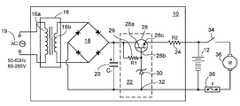
- FIG. 1is a circuit schematic of a household device battery charger.
- FIG. 2is a circuit schematic of an alternative household device battery charger implemented using a switch-mode AC/DC adapter circuit.
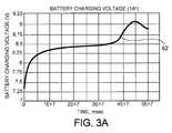
- FIGS. 3A-Care a series of plots that illustrate exemplary battery charging voltage, battery charging current, and trickle charging current behaviors, respectively, for a 7.2 V NiCd rechargeable battery using a conventional charger circuit.
- FIGS. 4A-Bare a series of plots that illustrate exemplary battery charging voltage and battery charging current behaviors using an exemplary embodiment of the household device battery charger and a conventional charger circuit respectively.
- an exemplary household device charger or rechargeable battery charger device 10 to charge at least one rechargeable battery 12 that has at least one rechargeable cellis shown.
- the rechargeable battery 12is typically used in household or portable electronic devices such as, for example, wireless vacuum cleaners, cordless telephones and rechargeable flashlights.
- the rechargeable battery 12includes NiCd or NiMH cells having cadmium or hydrogen-absorbing alloy for the anode and nickel for the cathode.
- FIG. 1shows a single rechargeable battery 12
- the rechargeable battery charger device 10may be adapted to receive and charge two or more rechargeable batteries at the same time. Further, the rechargeable battery charger device 10 may charge different battery types including, for example, cylindrical batteries or prismatic batteries.
- the rechargeable battery charger device 10is electrically coupled to an external AC power source 14 , such as a source providing power at a rating of 85V-265V and 50 Hz-60 Hz.
- the AC power source 14is coupled to a transformer 16 in the rechargeable battery device 10 .
- the transformer 16is a current-limited linear transformer having a primary winding 16 a and a secondary winding 16 b.
- the rechargeable battery charger device 10includes a rectifier circuit, e.g., a full wave rectifier circuit 18 coupled to the secondary winding 16 b of the transformer 16 .
- a stepped-down AC voltageis induced at the secondary winding 16 b from the AC power source 14 coupled to the primary winding 16 a of the transformer 16 .
- the full wave rectifier circuit 18converts the stepped-down AC voltage to a low DC voltage (e.g., 1.5-14V) that is at a level suitable for charging the rechargeable battery 12 , e.g., DC voltages at levels of approximately between 1.0-1.5 V for each NiCD or NiMH cell described above. Other types of cells may have different voltage levels.
- a low DC voltagee.g. 1.5-14V
- DC voltagesat levels of approximately between 1.0-1.5 V for each NiCD or NiMH cell described above.
- Other types of cellsmay have different voltage levels.
- a filter capacitor 20is coupled across the output of the full wave rectifier circuit 18 .
- An open circuit voltage across such a filter capacitor 20would be about 50% higher than the voltage across the rechargeable battery 12 .
- the voltage difference between the filter capacitor 20 and the rechargeable battery 12decreases, while supplying nominal charging current.
- the full wave rectifier circuit 18is coupled to a voltage regulator circuit 22 which, in turn, is connected to a current limiting resistor 24 .
- the voltage regulator circuit 22includes a resistor 26 , a transistor, e.g., bi-polar junction transistor 28 , having a current sink terminal, e.g., collector 28 a , a control terminal, e.g., base 28 b , and a current source terminal, e.g., emitter 28 c , and a diode, e.g. Zener diode 30 , coupled in reverse bias between the control terminal 28 b of the transistor 28 and a ground terminal 32 .
- the transistor 28is a field effect transistor.
- the voltage regulator circuit 22is implemented by an integrated voltage regulator chip, such as, for example, a three-terminal adjustable linear voltage regulator chip (LM 317).
- LM 317three-terminal adjustable linear voltage regulator chip
- a value of the output voltage of the voltage regulator circuit 22is a function of the maximum continuous charging voltage that is permissible across the rechargeable battery 12 .
- the maximum charging voltage across the rechargeable battery 12 and thus the value of the output voltage across the terminals of the voltage regulator circuit 22is selected to be higher than 7.2 V (e.g., 8.4 V).
- the voltage drop between the control 28 b and current source 28 c terminals for a bipolar junction transistor (transistor 28 )is typically around 0.6 V.
- a Zener diode having a reverse breakdown voltage characteristic at 9 V (0.6V plus 8.4V)is provided as the diode 30 to compensate for the voltage drop.
- the resistance value of the current limiting resistor 24is related to the desired charging current, the average difference between the charging voltage across the rechargeable battery 12 and the value of the output voltage of the voltage regulator circuit 22 .
- the value of the output voltage of the voltage regulator circuit 22is selected to be 8.4 V (the maximum charging voltage across the rechargeable battery 12 ) Accordingly, if the average battery charging voltage is 7.8 V, and the desired charging current is 150 mA, the resistance value of the current limiting resistor 24 is around (8.4 V-7.8 V)/0.15 A ⁇ 4 Ohms.
- the desired charging current for the rechargeable battery charger device 10is selected based on the time available for charging.
- the charging current to be used in the rechargeable battery charger device 10is selected to be an average of C/10 (10 hours charge rate).
- the resistance value of the current limiting resistor 24 in the rechargeable battery charger device 10is also selected to limit the trickle charging current to be below a predetermined limit.
- the voltage across the rechargeable battery 12approaches the value of the output voltage across the terminals of the voltage regulator circuit 22 , e.g., 8.4 V (1.4 V/rechargeable cell)
- the charging currentdrops to a trickle charge value that is below the predetermined limit.
- the charging current supplied by the rechargeable battery charger device 10automatically drops to C/50 or lower.
- the rechargeable battery 12is maintained in a healthy state regardless of the usage or charging pattern.
- the rechargeable battery 12is connected to a load, e.g., load motor 36 of a typical household device, e.g., a portable vacuum cleaner through a switch 34 .
- a fuse 38is typically included in the rechargeable battery charger device 10 to protect the rechargeable battery 12 and load motor 36 from load currents greater than a predetermined rated value (e.g., ⁇ 20 A).
- the transformer 16 and the full wave rectifier circuit 18are disposed within an AC power source adapter (not shown), rather than within the rechargeable battery charger device 10 ( FIG. 1 ). Accordingly, the AC/DC adapter would receive an AC voltage and provide a DC voltage. In other embodiments the transformer 16 is disposed in an AC power source adapter (not shown), and the full wave rectifier circuit 18 is part of the rechargeable battery charger device, similar to that shown in FIG. 1 .
- FIG. 2an alternative arrangement for the rechargeable battery charger device, is a switch-mode AC/DC adapter circuit 40 as shown.
- This arrangement 40includes a full wave rectifier 41 on the primary side of the transformer 42 and has the voltage regulator implemented using an integrated controller device.
- at least one rechargeable battery 12is connected across the output terminals of the switch-mode AC/DC adapter circuit 40 .
- the switch-mode AC/DC adapter circuit 40receives and charges more than one rechargeable battery at the same time.
- the switch-mode AC/DC adapter circuit 40may charge different battery types including, for example, cylindrical batteries or prismatic batteries.
- the rechargeable battery 12is connected to a load, e.g., load motor 36 of a vacuum cleaner, through switch 34 and fuse 38 .
- the switch-mode AC/DC adapter circuit 40includes the transformer 42 having a primary winding 42 a and a secondary winding 42 b . Accordingly, the switch-mode AC/DC adapter circuit 40 has a primary side 40 a and a secondary side 40 b.
- the primary side 40 a of the switch-mode AC/DC adapter circuit 40includes a full wave rectifier circuit 42 coupled to an AC power source 14 and a capacitor 44 coupled across the output terminals of the full wave rectifier circuit 42 .
- a switching transistor 46is also connected in series with the primary winding 42 a of the transformer 42 .
- the switching transistor 46is implemented using a metal-oxide-semiconductor field-effect transistor (MOSFET).
- MOSFETmetal-oxide-semiconductor field-effect transistor
- a primary controller 50controls the switching cycle of the switching transistor 46 . Accordingly, the primary controller 50 turns the switching transistor 46 on and off with a feedback-controlled duty cycle.
- the secondary side 40 b of the switch-mode AC/DC adapter circuit 40includes a rectifier diode 52 connected in series with the secondary winding 42 B of the transformer 42 and a filter capacitor 54 connected to the anode terminal of the rectifier diode 52 .
- the terminals of the filter capacitor 54are further coupled to a voltage divider circuit 56 having resistors 56 a and 56 b.
- a secondary side controller 58is coupled across resistor 56 b of the voltage divider circuit 56 .
- the secondary side controller 58has control loops to perform both current and voltage regulation.
- the secondary side controller 58is implemented by an integrated controller chip, such as, for example, TSM1052 from STMicroelectronics, Geneva, Switzerland.
- the secondary side controller 58further transmits the feedback signals, V out and I out to the primary controller 50 through an isolated optical transmission path 60 .
- FIGS. 3A-Cillustrate exemplary battery charging voltage 62 , battery charging current 64 , and trickle charging current 66 behaviors, respectively, for a 7.2 V NiCd rechargeable battery using a conventional charger circuit (not shown).
- the trickle charging current 66remains significant even after the rechargeable battery is fully charged (approximately 10 hours).
- the instantaneous trickle charging current 66 after 48 hours of chargefluctuates so that the peak value is around 330 mA.
- the recommended trickle charge limitis around 30 mA, e.g., C/50 or 6 ⁇ 1500/50 at a one hour charge rate. Consequently, overcharging the rechargeable battery 12 continuously in this manner shortens the life of the rechargeable battery 12 and reduces the runtime of the household device.
- FIGS. 4A-Billustrate exemplary battery charging voltage 68 (voltage across the at least one rechargeable battery 12 in FIG. 1 ) and battery charging current 70 behaviors, respectively, for six 1500 mAh NiCd cells in series subjected to over 24 hours of charge at a constant voltage of 8.4 V and current limited up to 500 mA using a rechargeable battery charger of the type shown in either of FIG. 1 or FIG. 2 .
- Exemplary battery charging voltage 72 , and the battery charging current 74 behaviors, respectively, for the six 1500 mAh NiCd cells in series subjected to the over 24 hours of charge at a constant voltage of 8.4 V using a conventional rechargeable battery charger circuitare also shown.
- a maximum charging current of about 500 mAthe NiCD batteries that were initially substantially entirely depleted, would become fully charged in approximately 10 hours.
- the battery charging voltagee.g., exemplary battery charging voltages 68 , 72
- the battery charging voltage 68at the output terminals of the rechargeable battery charger device 10 increases and reaches an average voltage level of 8.2-8.6 V (8.4V plus/minus 0.2V).
- the battery charging voltage 68corresponding to embodiments of the rechargeable battery charger device 10 , e.g., circuit shown in FIG. 1 , is maintained at a constant voltage level.
- the battery charging voltage 72 corresponding to a conventional rechargeable battery charger circuitis also shown in FIG. 4A .
- the conventional rechargeable battery charger circuitdepicts uneven output voltage.
- the rechargeable battery charger device 10causes the fluctuations, e.g., spikes appearing in the exemplary battery charging current 70 , to average to below a very low predetermined trickle charge value, e.g., lower than C/50.
- a very low predetermined trickle charge valuee.g., lower than C/50.
- the battery charging current 70continues to remain at the very low predetermined trickle charge value until the rechargeable battery 12 is removed from the rechargeable battery charger device 10 .
Landscapes
- Engineering & Computer Science (AREA)
- Power Engineering (AREA)
- Charge And Discharge Circuits For Batteries Or The Like (AREA)
- Secondary Cells (AREA)
Abstract
Description
Claims (20)
Priority Applications (7)
| Application Number | Priority Date | Filing Date | Title |
|---|---|---|---|
| US11/867,110US9071073B2 (en) | 2007-10-04 | 2007-10-04 | Household device continuous battery charger utilizing a constant voltage regulator |
| EP08835426.1AEP2206214B1 (en) | 2007-10-04 | 2008-10-01 | Household device battery charger |
| PCT/IB2008/053994WO2009044350A1 (en) | 2007-10-04 | 2008-10-01 | Household device battery charger |
| CN200880110013ACN101816111A (en) | 2007-10-04 | 2008-10-01 | Household device battery charger |
| JP2010526415AJP2010541527A (en) | 2007-10-04 | 2008-10-01 | Battery charger for household equipment |
| JP2014234414AJP6017517B2 (en) | 2007-10-04 | 2014-11-19 | Battery charger for household equipment |
| JP2016188495AJP2017034995A (en) | 2007-10-04 | 2016-09-27 | Battery charger for household equipment |
Applications Claiming Priority (1)
| Application Number | Priority Date | Filing Date | Title |
|---|---|---|---|
| US11/867,110US9071073B2 (en) | 2007-10-04 | 2007-10-04 | Household device continuous battery charger utilizing a constant voltage regulator |
Publications (2)
| Publication Number | Publication Date |
|---|---|
| US20090091298A1 US20090091298A1 (en) | 2009-04-09 |
| US9071073B2true US9071073B2 (en) | 2015-06-30 |
Family
ID=40202151
Family Applications (1)
| Application Number | Title | Priority Date | Filing Date |
|---|---|---|---|
| US11/867,110Expired - Fee RelatedUS9071073B2 (en) | 2007-10-04 | 2007-10-04 | Household device continuous battery charger utilizing a constant voltage regulator |
Country Status (5)
| Country | Link |
|---|---|
| US (1) | US9071073B2 (en) |
| EP (1) | EP2206214B1 (en) |
| JP (3) | JP2010541527A (en) |
| CN (1) | CN101816111A (en) |
| WO (1) | WO2009044350A1 (en) |
Cited By (18)
| Publication number | Priority date | Publication date | Assignee | Title |
|---|---|---|---|---|
| US10578674B2 (en) | 2016-06-22 | 2020-03-03 | The Gillette Company Llc | Personal consumer product with thermal control circuitry diagnostics and methods thereof |
| US10652956B2 (en) | 2016-06-22 | 2020-05-12 | The Gillette Company Llc | Personal consumer product with thermal control circuitry and methods thereof |
| US11233392B2 (en)* | 2017-10-26 | 2022-01-25 | Endress+Hauser Se+ Co. Kg | Electronic field device with transceiver protecting circuit |
| US11247357B2 (en) | 2017-01-20 | 2022-02-15 | The Gillette Company Llc | Heating delivery element for a shaving razor |
| US11571828B2 (en) | 2018-03-30 | 2023-02-07 | The Gillette Company Llc | Shaving razor handle |
| US11577417B2 (en) | 2018-03-30 | 2023-02-14 | The Gillette Company Llc | Razor handle with a pivoting portion |
| US11590669B2 (en) | 2018-03-30 | 2023-02-28 | The Gillette Company Llc | Razor handle with movable members |
| US11607820B2 (en) | 2018-03-30 | 2023-03-21 | The Gillette Company Llc | Razor handle with movable members |
| US11691307B2 (en) | 2018-03-30 | 2023-07-04 | The Gillette Company Llc | Razor handle with a pivoting portion |
| US11766795B2 (en) | 2018-03-30 | 2023-09-26 | The Gillette Company Llc | Razor handle with a pivoting portion |
| US11780105B2 (en) | 2018-03-30 | 2023-10-10 | The Gillette Company Llc | Razor handle with a pivoting portion |
| US11806885B2 (en) | 2018-03-30 | 2023-11-07 | The Gillette Company Llc | Razor handle with movable members |
| US11945128B2 (en) | 2018-03-30 | 2024-04-02 | The Gillette Company Llc | Razor handle with a pivoting portion |
| USD1021248S1 (en) | 2018-03-30 | 2024-04-02 | The Gillette Company Llc | Shaving razor cartridge |
| US12208531B2 (en) | 2018-03-30 | 2025-01-28 | The Gillette Company Llc | Razor handle with a rigid member |
| US12226922B2 (en) | 2018-03-30 | 2025-02-18 | The Gillette Company Llc | Razor handle with a pivoting portion |
| US12240135B2 (en) | 2018-03-30 | 2025-03-04 | The Gillette Company Llc | Razor handle with a pivoting portion |
| US12280513B2 (en) | 2018-03-30 | 2025-04-22 | The Gillette Company Llc | Shaving razor system |
Families Citing this family (6)
| Publication number | Priority date | Publication date | Assignee | Title |
|---|---|---|---|---|
| CN102223084B (en)* | 2011-06-16 | 2012-11-07 | 湖北网安科技有限公司 | Alternating-current constant-current source circuit |
| CN103236568B (en)* | 2013-05-03 | 2016-03-30 | 努比亚技术有限公司 | Charging method and charging system |
| US20140362608A1 (en)* | 2013-06-11 | 2014-12-11 | System General Corp. | Method for programmable primary-side-regulated power converter |
| CN106104964A (en)* | 2015-02-10 | 2016-11-09 | 存点有限公司 | For the high power charging device that energy storing device is charged |
| EP3282550B1 (en) | 2016-02-05 | 2020-04-15 | Guangdong Oppo Mobile Telecommunications Corp., Ltd. | Adapter and charging control method |
| CN111711254B (en) | 2020-08-06 | 2020-11-24 | 苏州明纬科技有限公司 | Universal charging device and charging method thereof |
Citations (23)
| Publication number | Priority date | Publication date | Assignee | Title |
|---|---|---|---|---|
| US3214668A (en)* | 1962-12-04 | 1965-10-26 | Gen Devices Inc | Transistorized voltage regulator |
| US3327198A (en)* | 1964-12-15 | 1967-06-20 | Benjamin Electronic Sound Corp | Battery charging system and indicator |
| US3336521A (en)* | 1964-09-09 | 1967-08-15 | Electro Optical Systems Inc | Converter/regulator feedback reference |
| US3678363A (en)* | 1970-04-06 | 1972-07-18 | Globe Union Inc | Automatic battery charger with multiple rate charging |
| US3735233A (en)* | 1970-08-24 | 1973-05-22 | Globe Union Inc | Battery charger apparatus having multiple modes of operation and automatic switching therebetween |
| US3947752A (en)* | 1974-06-04 | 1976-03-30 | Motorola, Inc. | Circuit for converting alternating current voltages to a constant magnitude direct current voltage |
| US4034281A (en)* | 1974-07-25 | 1977-07-05 | Sanken Electric Company Limited | Direct current power supply with a transistor chopper |
| US4233553A (en) | 1978-05-10 | 1980-11-11 | Ault, Inc. | Automatic dual mode battery charger |
| US4412265A (en)* | 1981-11-27 | 1983-10-25 | Tokheim Corporation | Intrinsic barrier |
| US4631468A (en) | 1983-04-30 | 1986-12-23 | Sharp Kabushiki Kaisha | Battery charging circuit for electronic apparatus |
| US4636709A (en)* | 1983-07-29 | 1987-01-13 | Sony Corporation | Regulated DC power supply |
| US4965506A (en)* | 1989-02-14 | 1990-10-23 | U.S. Philips Corporation | Power-supply circuit having circuitry for switching from a battery charging mode to a battery trickle-charging mode |
| US5028860A (en) | 1989-01-20 | 1991-07-02 | Sony Corporation | Battery charge apparatus controlled by detecting charge current with constant charge voltage |
| US5532524A (en)* | 1994-05-11 | 1996-07-02 | Apple Computer, Inc. | Distributed power regulation in a portable computer to optimize heat dissipation and maximize battery run-time for various power modes |
| US5592069A (en)* | 1992-10-07 | 1997-01-07 | Dallas Semiconductor Corporation | Battery charger |
| US5604425A (en)* | 1994-08-08 | 1997-02-18 | Thomson Consumer Electronics, Inc. | Power limiting regulator |
| US5969506A (en) | 1997-08-11 | 1999-10-19 | C & K Systems, Inc. | Apparatus and method for rapid bulk charging of a lead acid battery |
| US6094040A (en)* | 1998-03-20 | 2000-07-25 | Endress + Hauser Gmbh + Co. | Voltage regulator circuit |
| US6184664B1 (en)* | 1997-05-12 | 2001-02-06 | Em Microelectronics-Marin Sa | Voltage regulator circuit for suppressing latch-up phenomenon |
| US20020171405A1 (en)* | 2000-02-08 | 2002-11-21 | Yuichi Watanabe | Apparatus and circuit for power supply, and apparatus for controlling large current load Apparatus and circuit for power supply,and apparatus for controlling large current load |
| US7261979B2 (en) | 2004-02-06 | 2007-08-28 | A123 Systems, Inc. | Lithium secondary cell with high charge and discharge rate capability |
| EP1865272A1 (en) | 2006-06-09 | 2007-12-12 | Honeywell Technologies Sarl | Water boiler |
| US7489109B1 (en)* | 2004-06-23 | 2009-02-10 | Intersil Americas Inc. | Integrated battery charger and system regulator circuit |
Family Cites Families (14)
| Publication number | Priority date | Publication date | Assignee | Title |
|---|---|---|---|---|
| JPS5948110B2 (en)* | 1980-10-11 | 1984-11-24 | 松下電工株式会社 | rechargeable electrical equipment |
| JPS61132046A (en)* | 1984-11-30 | 1986-06-19 | 新電元工業株式会社 | Atmospheric pressure adjustor for magnet type ac generator |
| JP3456710B2 (en)* | 1992-02-26 | 2003-10-14 | 松下電器産業株式会社 | Power system |
| JPH07222375A (en) | 1994-01-31 | 1995-08-18 | Tec Corp | Emergency lighting unit |
| JPH0837738A (en) | 1994-07-26 | 1996-02-06 | Oki Electric Ind Co Ltd | Battery charging circuit |
| JPH09121467A (en)* | 1995-10-24 | 1997-05-06 | Rohm Co Ltd | Secondary battery charger and electric machine employing it |
| JP3620118B2 (en)* | 1995-10-24 | 2005-02-16 | 松下電器産業株式会社 | Constant current / constant voltage charger |
| JP2000134816A (en)* | 1998-10-27 | 2000-05-12 | Toshiba Corp | Electronic equipment and AC adapter |
| JP2002199613A (en)* | 2000-12-26 | 2002-07-12 | Sony Corp | Charging circuit for secondary battery |
| SE0200546D0 (en)* | 2002-02-22 | 2002-02-22 | Creator Teknisk Utveckling Ab | Device for a battery charger |
| JP2003264933A (en)* | 2002-03-11 | 2003-09-19 | Orion Denki Kk | Input protection circuit, unit of electrical apparatus, and system of electrical apparatuses |
| JP2004328934A (en)* | 2003-04-25 | 2004-11-18 | Japan Storage Battery Co Ltd | Battery charge control device |
| JP2005204365A (en)* | 2004-01-13 | 2005-07-28 | Japan Storage Battery Co Ltd | Battery pack |
| JP4406932B2 (en)* | 2005-09-13 | 2010-02-03 | 日立工機株式会社 | Charger |
- 2007
- 2007-10-04USUS11/867,110patent/US9071073B2/ennot_activeExpired - Fee Related
- 2008
- 2008-10-01EPEP08835426.1Apatent/EP2206214B1/enactiveActive
- 2008-10-01JPJP2010526415Apatent/JP2010541527A/enactivePending
- 2008-10-01WOPCT/IB2008/053994patent/WO2009044350A1/enactiveApplication Filing
- 2008-10-01CNCN200880110013Apatent/CN101816111A/enactivePending
- 2014
- 2014-11-19JPJP2014234414Apatent/JP6017517B2/ennot_activeExpired - Fee Related
- 2016
- 2016-09-27JPJP2016188495Apatent/JP2017034995A/enactivePending
Patent Citations (23)
| Publication number | Priority date | Publication date | Assignee | Title |
|---|---|---|---|---|
| US3214668A (en)* | 1962-12-04 | 1965-10-26 | Gen Devices Inc | Transistorized voltage regulator |
| US3336521A (en)* | 1964-09-09 | 1967-08-15 | Electro Optical Systems Inc | Converter/regulator feedback reference |
| US3327198A (en)* | 1964-12-15 | 1967-06-20 | Benjamin Electronic Sound Corp | Battery charging system and indicator |
| US3678363A (en)* | 1970-04-06 | 1972-07-18 | Globe Union Inc | Automatic battery charger with multiple rate charging |
| US3735233A (en)* | 1970-08-24 | 1973-05-22 | Globe Union Inc | Battery charger apparatus having multiple modes of operation and automatic switching therebetween |
| US3947752A (en)* | 1974-06-04 | 1976-03-30 | Motorola, Inc. | Circuit for converting alternating current voltages to a constant magnitude direct current voltage |
| US4034281A (en)* | 1974-07-25 | 1977-07-05 | Sanken Electric Company Limited | Direct current power supply with a transistor chopper |
| US4233553A (en) | 1978-05-10 | 1980-11-11 | Ault, Inc. | Automatic dual mode battery charger |
| US4412265A (en)* | 1981-11-27 | 1983-10-25 | Tokheim Corporation | Intrinsic barrier |
| US4631468A (en) | 1983-04-30 | 1986-12-23 | Sharp Kabushiki Kaisha | Battery charging circuit for electronic apparatus |
| US4636709A (en)* | 1983-07-29 | 1987-01-13 | Sony Corporation | Regulated DC power supply |
| US5028860A (en) | 1989-01-20 | 1991-07-02 | Sony Corporation | Battery charge apparatus controlled by detecting charge current with constant charge voltage |
| US4965506A (en)* | 1989-02-14 | 1990-10-23 | U.S. Philips Corporation | Power-supply circuit having circuitry for switching from a battery charging mode to a battery trickle-charging mode |
| US5592069A (en)* | 1992-10-07 | 1997-01-07 | Dallas Semiconductor Corporation | Battery charger |
| US5532524A (en)* | 1994-05-11 | 1996-07-02 | Apple Computer, Inc. | Distributed power regulation in a portable computer to optimize heat dissipation and maximize battery run-time for various power modes |
| US5604425A (en)* | 1994-08-08 | 1997-02-18 | Thomson Consumer Electronics, Inc. | Power limiting regulator |
| US6184664B1 (en)* | 1997-05-12 | 2001-02-06 | Em Microelectronics-Marin Sa | Voltage regulator circuit for suppressing latch-up phenomenon |
| US5969506A (en) | 1997-08-11 | 1999-10-19 | C & K Systems, Inc. | Apparatus and method for rapid bulk charging of a lead acid battery |
| US6094040A (en)* | 1998-03-20 | 2000-07-25 | Endress + Hauser Gmbh + Co. | Voltage regulator circuit |
| US20020171405A1 (en)* | 2000-02-08 | 2002-11-21 | Yuichi Watanabe | Apparatus and circuit for power supply, and apparatus for controlling large current load Apparatus and circuit for power supply,and apparatus for controlling large current load |
| US7261979B2 (en) | 2004-02-06 | 2007-08-28 | A123 Systems, Inc. | Lithium secondary cell with high charge and discharge rate capability |
| US7489109B1 (en)* | 2004-06-23 | 2009-02-10 | Intersil Americas Inc. | Integrated battery charger and system regulator circuit |
| EP1865272A1 (en) | 2006-06-09 | 2007-12-12 | Honeywell Technologies Sarl | Water boiler |
Non-Patent Citations (3)
| Title |
|---|
| LinkSwitch-XT. Design Guide, Application Note AN-40. Power Integrations. Nov. 2005. |
| Swiffer Sweep and Vac Instruction Manual (Two Pages). |
| TSM1052: CC/CV controller for chargers and adapters. www.st.com/powermanagement. |
Cited By (19)
| Publication number | Priority date | Publication date | Assignee | Title |
|---|---|---|---|---|
| US10578674B2 (en) | 2016-06-22 | 2020-03-03 | The Gillette Company Llc | Personal consumer product with thermal control circuitry diagnostics and methods thereof |
| US10652956B2 (en) | 2016-06-22 | 2020-05-12 | The Gillette Company Llc | Personal consumer product with thermal control circuitry and methods thereof |
| US11558931B2 (en) | 2016-06-22 | 2023-01-17 | The Gillette Company Llc | Personal consumer product with thermal control circuitry |
| US11247357B2 (en) | 2017-01-20 | 2022-02-15 | The Gillette Company Llc | Heating delivery element for a shaving razor |
| US11233392B2 (en)* | 2017-10-26 | 2022-01-25 | Endress+Hauser Se+ Co. Kg | Electronic field device with transceiver protecting circuit |
| US11607820B2 (en) | 2018-03-30 | 2023-03-21 | The Gillette Company Llc | Razor handle with movable members |
| US11806885B2 (en) | 2018-03-30 | 2023-11-07 | The Gillette Company Llc | Razor handle with movable members |
| US11590669B2 (en) | 2018-03-30 | 2023-02-28 | The Gillette Company Llc | Razor handle with movable members |
| US11571828B2 (en) | 2018-03-30 | 2023-02-07 | The Gillette Company Llc | Shaving razor handle |
| US11691307B2 (en) | 2018-03-30 | 2023-07-04 | The Gillette Company Llc | Razor handle with a pivoting portion |
| US11766795B2 (en) | 2018-03-30 | 2023-09-26 | The Gillette Company Llc | Razor handle with a pivoting portion |
| US11780105B2 (en) | 2018-03-30 | 2023-10-10 | The Gillette Company Llc | Razor handle with a pivoting portion |
| US11577417B2 (en) | 2018-03-30 | 2023-02-14 | The Gillette Company Llc | Razor handle with a pivoting portion |
| US11945128B2 (en) | 2018-03-30 | 2024-04-02 | The Gillette Company Llc | Razor handle with a pivoting portion |
| USD1021248S1 (en) | 2018-03-30 | 2024-04-02 | The Gillette Company Llc | Shaving razor cartridge |
| US12208531B2 (en) | 2018-03-30 | 2025-01-28 | The Gillette Company Llc | Razor handle with a rigid member |
| US12226922B2 (en) | 2018-03-30 | 2025-02-18 | The Gillette Company Llc | Razor handle with a pivoting portion |
| US12240135B2 (en) | 2018-03-30 | 2025-03-04 | The Gillette Company Llc | Razor handle with a pivoting portion |
| US12280513B2 (en) | 2018-03-30 | 2025-04-22 | The Gillette Company Llc | Shaving razor system |
Also Published As
| Publication number | Publication date |
|---|---|
| JP2017034995A (en) | 2017-02-09 |
| JP2010541527A (en) | 2010-12-24 |
| EP2206214A1 (en) | 2010-07-14 |
| EP2206214B1 (en) | 2020-01-22 |
| JP6017517B2 (en) | 2016-11-02 |
| WO2009044350A1 (en) | 2009-04-09 |
| JP2015062334A (en) | 2015-04-02 |
| US20090091298A1 (en) | 2009-04-09 |
| CN101816111A (en) | 2010-08-25 |
Similar Documents
| Publication | Publication Date | Title |
|---|---|---|
| US9071073B2 (en) | Household device continuous battery charger utilizing a constant voltage regulator | |
| CN100461582C (en) | Battery | |
| US9077198B2 (en) | Battery charging method and circuit | |
| US8860372B2 (en) | Multiple cell battery charger configured with a parallel topology | |
| US8378632B2 (en) | Circuit arrangement with multiple batteries | |
| US8368346B2 (en) | Portable energy storage and charging device | |
| CN101345432B (en) | How to charge the battery pack | |
| EP0752748B1 (en) | Multiple function battery charger, self-configuring as supply voltage regulator for battery powered apparatuses | |
| US7394225B2 (en) | Pseudo constant current multiple cell battery charger configured with a parallel topology | |
| JPS58224529A (en) | Electronic power source circuit | |
| US4460863A (en) | Battery charging flashlight circuit | |
| US8093865B2 (en) | Charging device with backflow prevention | |
| CN216451158U (en) | Power supply circuit of cooking utensil and cooking utensil | |
| US12322993B2 (en) | Battery charger with a plurality of secondary transformer circuits | |
| US11095133B2 (en) | Simple battery and charger system | |
| CN209860651U (en) | Lithium battery charger circuit | |
| Kester et al. | SECTION 5 BATTERY CHARGERS | |
| JPS638708B2 (en) | ||
| JP2007089309A (en) | Charger for portable electronic devices | |
| JP2006320185A (en) | Charging circuit for storage battery |
Legal Events
| Date | Code | Title | Description |
|---|---|---|---|
| AS | Assignment | Owner name:GILLETTE COMPANY, THE, MASSACHUSETTS Free format text:ASSIGNMENT OF ASSIGNORS INTEREST;ASSIGNORS:BOURILKOV, JORDAN T.;KLEIN, DAVID N.;BAE, IN TAE;AND OTHERS;REEL/FRAME:020228/0589;SIGNING DATES FROM 20071026 TO 20071203 Owner name:GILLETTE COMPANY, THE, MASSACHUSETTS Free format text:ASSIGNMENT OF ASSIGNORS INTEREST;ASSIGNORS:BOURILKOV, JORDAN T.;KLEIN, DAVID N.;BAE, IN TAE;AND OTHERS;SIGNING DATES FROM 20071026 TO 20071203;REEL/FRAME:020228/0589 | |
| FEPP | Fee payment procedure | Free format text:PAYOR NUMBER ASSIGNED (ORIGINAL EVENT CODE: ASPN); ENTITY STATUS OF PATENT OWNER: LARGE ENTITY | |
| STCF | Information on status: patent grant | Free format text:PATENTED CASE | |
| AS | Assignment | Owner name:DURACELL U.S. OPERATIONS, INC., DELAWARE Free format text:ASSIGNMENT OF ASSIGNORS INTEREST;ASSIGNOR:THE GILLETTE COMPANY;REEL/FRAME:037931/0489 Effective date:20160225 | |
| MAFP | Maintenance fee payment | Free format text:PAYMENT OF MAINTENANCE FEE, 4TH YEAR, LARGE ENTITY (ORIGINAL EVENT CODE: M1551); ENTITY STATUS OF PATENT OWNER: LARGE ENTITY Year of fee payment:4 | |
| FEPP | Fee payment procedure | Free format text:MAINTENANCE FEE REMINDER MAILED (ORIGINAL EVENT CODE: REM.); ENTITY STATUS OF PATENT OWNER: LARGE ENTITY | |
| LAPS | Lapse for failure to pay maintenance fees | Free format text:PATENT EXPIRED FOR FAILURE TO PAY MAINTENANCE FEES (ORIGINAL EVENT CODE: EXP.); ENTITY STATUS OF PATENT OWNER: LARGE ENTITY | |
| STCH | Information on status: patent discontinuation | Free format text:PATENT EXPIRED DUE TO NONPAYMENT OF MAINTENANCE FEES UNDER 37 CFR 1.362 | |
| FP | Lapsed due to failure to pay maintenance fee | Effective date:20230630 |