US9070669B2 - Wettable lead ends on a flat-pack no-lead microelectronic package - Google Patents
Wettable lead ends on a flat-pack no-lead microelectronic packageDownload PDFInfo
- Publication number
- US9070669B2 US9070669B2US13/673,212US201213673212AUS9070669B2US 9070669 B2US9070669 B2US 9070669B2US 201213673212 AUS201213673212 AUS 201213673212AUS 9070669 B2US9070669 B2US 9070669B2
- Authority
- US
- United States
- Prior art keywords
- solder
- package
- lead
- lead frame
- manufacturing
- Prior art date
- Legal status (The legal status is an assumption and is not a legal conclusion. Google has not performed a legal analysis and makes no representation as to the accuracy of the status listed.)
- Active, expires
Links
Images


Classifications
- H—ELECTRICITY
- H01—ELECTRIC ELEMENTS
- H01L—SEMICONDUCTOR DEVICES NOT COVERED BY CLASS H10
- H01L21/00—Processes or apparatus adapted for the manufacture or treatment of semiconductor or solid state devices or of parts thereof
- H01L21/02—Manufacture or treatment of semiconductor devices or of parts thereof
- H01L21/04—Manufacture or treatment of semiconductor devices or of parts thereof the devices having potential barriers, e.g. a PN junction, depletion layer or carrier concentration layer
- H01L21/48—Manufacture or treatment of parts, e.g. containers, prior to assembly of the devices, using processes not provided for in a single one of the groups H01L21/18 - H01L21/326 or H10D48/04 - H10D48/07
- H01L21/4814—Conductive parts
- H01L21/4821—Flat leads, e.g. lead frames with or without insulating supports
- H—ELECTRICITY
- H01—ELECTRIC ELEMENTS
- H01L—SEMICONDUCTOR DEVICES NOT COVERED BY CLASS H10
- H01L23/00—Details of semiconductor or other solid state devices
- H01L23/48—Arrangements for conducting electric current to or from the solid state body in operation, e.g. leads, terminal arrangements ; Selection of materials therefor
- H01L23/488—Arrangements for conducting electric current to or from the solid state body in operation, e.g. leads, terminal arrangements ; Selection of materials therefor consisting of soldered or bonded constructions
- H01L23/495—Lead-frames or other flat leads
- H01L23/49579—Lead-frames or other flat leads characterised by the materials of the lead frames or layers thereon
- H01L23/49582—Metallic layers on lead frames
- H—ELECTRICITY
- H01—ELECTRIC ELEMENTS
- H01L—SEMICONDUCTOR DEVICES NOT COVERED BY CLASS H10
- H01L24/00—Arrangements for connecting or disconnecting semiconductor or solid-state bodies; Methods or apparatus related thereto
- H01L24/93—Batch processes
- H01L24/95—Batch processes at chip-level, i.e. with connecting carried out on a plurality of singulated devices, i.e. on diced chips
- H01L24/97—Batch processes at chip-level, i.e. with connecting carried out on a plurality of singulated devices, i.e. on diced chips the devices being connected to a common substrate, e.g. interposer, said common substrate being separable into individual assemblies after connecting
- H—ELECTRICITY
- H01—ELECTRIC ELEMENTS
- H01L—SEMICONDUCTOR DEVICES NOT COVERED BY CLASS H10
- H01L2924/00—Indexing scheme for arrangements or methods for connecting or disconnecting semiconductor or solid-state bodies as covered by H01L24/00
- H01L2924/15—Details of package parts other than the semiconductor or other solid state devices to be connected
- H01L2924/181—Encapsulation
Definitions
- This inventionrelates generally to semiconductor device manufacturing, and more specifically to treatment of lead ends of flat-pack no-lead semiconductor device packages.
- a lead frame strip(hereinafter “strip”) is populated with a plurality of lead frames.
- a semiconductor or microelectronic deviceis mounted on each lead frame and encapsulated with a mold compound. Lead frames are separated during singulation of the strip to create individual semiconductor or microelectronic packages (hereinafter “package(s)”).
- a packageutilizes leads for externally providing and receiving signals and power.
- One type of packageis a flat-pack no-lead package where each lead, or terminal, is exposed at a bottom and at a side of the package.
- the base metal of the lead frame of a flat-pack no-lead packageis copper (Cu), and the oxide is a copper oxide, for example, Cu 2 O, CuO and CuO 2 .
- Soldertends to adhere to a surface that is solder wettable; however, copper oxide is not solder wettable.
- Solder pasteincludes solder and flux.
- a purpose of fluxis to clean and activate a surface of a base metal.
- FIG. 1is a flow diagram illustrating steps of a method of manufacturing a flat-pack no-lead package prior to singulation of a strip, in accordance with several embodiments of the invention.
- FIG. 2is plan view of a representative strip.
- FIG. 3is a corner of another representative strip showing one entire lead frame and portions of adjacent lead frames.
- FIG. 4is corner of a stencil that may be used with one method of manufacturing a flat-pack no-lead package in accordance with one embodiment of the invention.
- FIG. 5is a cut view of a four lead frame portion of a partially singulated strip on a work holder, a stencil, solder paste, and a wiper blade, prior to stencil printing.
- FIG. 6is a cut view of the four lead frame portion of the partially singulated strip on the work holder and the stencil of FIG. 5 , subsequent to stencil printing the solder paste on the lead frames of the strip.
- FIG. 7is a cut view of a four lead frame portion of a strip, a work holder, a stencil, and solder paste, prior to stencil printing.
- FIG. 8is a cut view of the four lead frame portion of the strip, the work holder and the stencil of FIG. 7 , subsequent to stencil printing the solder paste on the lead frames of the strip, wherein the solder paste is not printed on cut lanes.
- FIG. 9is a cut view of a two lead frame portion of a strip and showing solder paste on the two lead frame portion of the strip.
- FIG. 10is a cut view of the two lead frame portion of a strip of FIG. 9 , after reflow.
- FIG. 11is a cut view of the two lead frame portion of the strip of FIG. 10 after partial singulation.
- FIG. 12is a cut view of the two lead frame portion of the strip of FIG. 11 , after reflow.
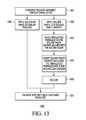
- FIG. 13is a flow diagram illustrating steps of a method of manufacturing a flat-pack no-lead package subsequent to singulation of a strip, in accordance with several other embodiments of the invention.
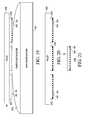
- FIG. 14is a cut view of solder paste, a stencil, and a solder paste carrier on a work holder, prior to stencil printing.
- FIG. 15is a cut view of the stencil, the solder paste carrier and the work holder of FIG. 14 , subsequent to stencil printing.
- FIG. 16is a cut view of the solder paste carrier of FIG. 15 showing solder paste on the solder paste carrier and showing three singulated packages in contact with the solder paste.
- FIG. 17is a cut view of the solder paste carrier, the solder paste on the solder paste carrier and the three singulated packages of FIG. 16 , in an upside-down position relative to FIG. 16 , on a reflow carrier prior to reflow.
- FIG. 18is a cut view of the solder paste carrier and three singulated flat-pack no-lead packages in accordance with the invention, on the reflow carrier, subsequent to reflow.
- FIG. 19is a cut view of three packages held by a pallet, wherein the bottom of the packages move into contact with molten solder as the pallet moves, thereby applying solder to cut ends of the lead frame of the package by solder wave.
- FIG. 20is a cut view of the three packages held by the pallet after solder was applied to the cut ends of the lead frame of the packages by solder wave.
- FIG. 21is a side view of a flat-pack no-lead package manufactured in accordance with one of the methods of FIGS. 1 and 13 , showing solder on the cut ends of the lead frame.
- One known method of manufacturing flat-pack no-lead packagespre-applies solder in a region of the lead end.
- This known methodincludes forming a through-hole feature, which is a hole that goes completely through a thickness of the lead frame metal, and requires solder (or another wettable material) to be applied prior to the molding process of assembly.
- solderor another wettable material
- This known methodalso requires that the pre-applied solder completely close off the through-hole feature.
- this known methodresults in solder on only a portion of the end of leads and not on the entire end of the leads.
- the lead frame of most known flat-pack no-lead packageshave at least one surface of exposed base metal, which occurs after, and as a result of, singulation. Such surface is in a plane approximately orthogonal to a plane of a bottom of the flat-pack no-lead package.
- Such exposed base metalis not considered a solder wettable (hereinafter “wettable”) surface.
- a solder filletis an extension of the solder joint at a side of a flat-pack no-lead package.
- a presence or absence of a solder filletcan be evidence of the quality of electrical connection between a lead of a flat-pack no-lead package and a PCB.
- Solderis not apt to wick up a side, or flank, of a lead of most known flat-pack no-lead packages because the solder is not likely to wet to an oxide on exposed metal at a cut end of the lead. Consequently, a solder fillet may not be seen during visual inspection because it does not exist or because it is very small.
- Some embodiments in accordance with the inventioncoat the exposed base metal at the cut end of the lead frame of a flat-pack no-lead package with solder to promote wetting during board mount.
- a flat-pack no-lead packagehereinafter “package”
- all portions of leads that are expected to receive solder during mounting to a printed circuit board (“PCB”)are advantageously wettable.
- a wettable cut end of the leads of a packagefacilitates formation of a solder fillet.
- solderadheres to the cut end of the lead at the sides of the package just as well as solder adheres to plated surfaces at the bottom of the package.
- the coating of solderencourages wicking of solder up the cut end of the leads at the sides of the package so that evidence of a solder joint is readily inspectable by a person or by an automated inspection device.
- the methods in accordance with the inventioneliminate, or at least greatly reduce, an area of the surface of base metal of the lead frame that remains exposed (and therefore not wettable) after package singulation.
- the methodsadvantageously provide that a surface of the lead frame located in a plane approximately orthogonal to a plane of a bottom of a package is wettable.
- a packagehas solder joints that are concealed under the package, after it is soldered, or mounted, to a PCB or another mounting surface. To properly perform visual inspection, it is desirable that at least some solder should be visible beyond a perimeter of the package after the package is mounted to a PCB.
- a package made in accordance with the inventionpromotes formation of inspectable solder joints of a package after it is mounted to a PCB.
- a package made in accordance with at least some embodiments of the inventionproduces a consistent solder joint that meets requirements of automated solder joint inspection systems.
- a package made in accordance with the inventionis more likely to result in inspectable solder joints after it is mounted to a PCB because no portion of leads that might be expected to receive solder during mounting to a PCB is exposed base metal.
- solderto the base metal of the lead frame that disadvantageously becomes exposed during singulation creates a feature that promotes wetting during board mount. This is sometimes called “pre-tinning” because tin (Sn) is a major component of solder, and to distinguish such application of solder from a later application of solder at the time of mounting the package to a PCB.
- the methods in accordance with some embodiments of the inventionpre-apply solder to up to 100% of the surface of each lead end. As a result, some embodiments provide a lead end that is wettable over a full width, i.e., cross-section, of the lead.
- FIG. 1is a flow diagram 100 illustrating steps of a method of manufacturing the package 2100 (see FIG. 21 ) in accordance with several embodiments of the invention.
- FIG. 2is plan view of a representative strip 200 .
- the representative strip 200can have three arrays 201 , 202 and 203 , each array having a plurality of lead frames 204 .
- FIG. 3is a corner of an array of another representative strip 300 showing one entire lead frame 301 and portions of adjacent lead frames 302 , 303 and 304 .
- the strip 300has a saw lane 305 between lead frames.
- FIG. 4is corner of a stencil 400 that may be used with the strip 300 during one of the methods of manufacturing the package 2100 illustrated by the flow diagram 100 .
- FIG. 5is a cut view of a four lead frame portion 500 of a partially singulated strip, such as strip 200 or 300 .
- the four lead frame portion 500includes mold compound 501 and base metal 503 .
- the exposed base metal 503has a plating 509 on it.
- platingmeans a coating of some material, other than solder or an organic surface protectant, on a surface of a lead frame to protect the lead frame from oxidation.
- the strip 300is plated while still in strip form with, for example, matte tin, nickel palladium, nickel palladium gold, or another wettable composition, using wet chemistry.
- FIG. 5is a cut view of a four lead frame portion 500 of a partially singulated strip, such as strip 200 or 300 .
- the four lead frame portion 500includes mold compound 501 and base metal 503 .
- the exposed base metal 503has a plating 509 on it.
- the term “plating” as used hereinmeans a coating of some material, other
- FIG. 5shows the four lead frame portion 500 on a work holder 502 ; a stencil, such as stencil 400 ; solder cream or solder paste (hereinafter “paste”) 506 ; and a squeegee, or wiper blade, 508 , prior to stencil printing.
- a size of a work holderis much larger than a size of a strip; therefore, more than one strip can be stencil printed in a single operation.
- FIG. 1describes steps for applying solder to the cut ends 504 (see FIG. 5 ) of the strip 300 prior to singulation of the strip. After singulation, the cut ends of the strip 300 will become the ends of the leads of a package.
- Manufacturing, or assembly, of the package 2100begins after step 101 which is standard assembly up to and including mold process. Typically, during standard assembly, step 101 , the exposed portion of the strip 300 was plated, and is therefore wettable. There is a left branch and a right branch in the flow diagram 100 . Each branch of the flow diagram 100 represents different embodiments.
- a first step 102comprises performing partial singulation of the strip 300 along the saw lanes 305 by sawing or by etching.
- all the base metal 503 of the lead frameis removed along each saw lane 305 of the strip 300 , thereby forming a trench, or channel, 510 , but the mold compound 501 along the saw lanes 305 is not completely removed.
- the phrase “partial singulation”means removing the entire cross-section of each lead along the saw lanes 305 , but not removing most, if any at all, of the mold compound 501 along the saw lanes.
- a width 306 of each saw lane 305 of strip 300is approximately 300 microns wide.
- a blade used for performing the partial singulation of step 102is at least 350 microns wide, in one embodiment.
- base metal 503 of the lead frame at the cut ends 504 of the lead framebecomes exposed along the saw lanes 305 of the strip 300 .
- paste 506is applied to the lead frame and to an area slightly beyond the cut end of the lead frame, i.e., slightly over the edges of the channels 510 produced in step 102 , but the paste is not applied over an entire width of the channel 510 .
- a stencil 400is used for applying paste 506 to the strip 300 .
- a distance 402 between some of the openings 401 in the stencil 400is about 100 microns in one embodiment, when the stencil is used with the strip 300 .
- FIG. 6is a cut view of the four lead frame portion 500 of the partially singulated strip 300 subsequent to step 103 .
- a reason for applying paste 506 to the entire lead frame of the strip 300is that the plated surface of the lead frame wets much more easily than does bare base metal 503 at the cut ends 504 of the lead frame. Therefore, if a small volume of paste 506 were applied only near, or at, the bare metal at the cut end of the lead frame, the paste may preferentially wet to the plated area and may “rob” solder from areas of bare base metal 503 , possibly leaving portion(s) of the cut end 504 of the lead frame without a coating of solder 1001 (see FIG.
- paste 506By applying paste 506 to the whole lead frame and beyond, there is ample paste to ensure that the cut ends 504 of the lead frame are coated with solder 1001 after reflow. In another embodiment, applying paste 506 only near the cut end of the lead frame of the strip 300 may be sufficient.
- the paste 506is Indalloy® with NC-SMQ90 flux vehicle, manufactured by The Indium Corporation of America, of Utica, N.Y. However, any alloy that is considered “solder” can be used.
- FIG. 6shows that paste 506 advantageously covers the formerly bare base metal 503 at the cut ends 504 of the lead frame.
- a first step 104comprises applying paste 506 to the lead frame of the strip 300 , prior to partial singulation.
- the step of applying paste 506in some embodiments includes a step of applying solder 1001 by one of: screen printing, solder performs, solder balls, using solder jetting, and using nanoparticle printing/spraying.
- FIG. 7is a cut view of a four lead frame portion 700 of a strip, such as strip 200 or 300 ; the work holder 502 ; a stencil, such as stencil 300 or 400 ; and paste 506 , prior to stencil printing. There are two choices in applying the paste 506 prior to singulation. Each of these two choices uses a different stencil 400 of its own design.
- the paste 506is applied over the entire portion of the lead frame that is not covered with mold compound 501 , except over the saw lanes 305 .
- An advantage of not applying paste 506 over the saw lanes 305is a reduction in a possibility that solder 1001 (see FIG. 10 ) will load the blade that will be used in step 106 for performing the partial singulation.
- FIG. 8is a cut view of the four lead frame portion 700 of the strip shown in FIG. 7 , subsequent to step 104 .
- FIG. 8shows that the paste 506 is not printed over the saw lanes 305 pursuant to the first choice.
- step 105is performed next.
- the paste 506is reflowed.
- the paste 506is reflowed at a temperature above the melting point of solder for approximately 45-90 seconds, but a time and a peak temperature depends on the type of paste.
- the paste 506is reflowed at a temperature of approximately 215° C. for 50-70 seconds for NC-SMC90 paste.
- FIG. 10is a cut view of a two lead frame portion 1000 after reflow of the strip shown in FIG. 9 .
- FIG. 10shows that there is now a layer, or coating, of solder 1001 on the base metal 503 of the lead frame. Regarding the thickness of the coating of solder: thinner is better. Excessive solder 1001 may result in a co-planarity issue. If there are two leads with excessive solder that are located on either side of a lead with little solder, the middle lead may not properly contact the PCB at final assembly.
- step 106the metal of the lead frame is removed along saw lanes 305 by sawing or by etching, similar to step 102 .
- FIG. 11is a cut view of a two lead frame portion 1100 showing solder 1001 on the lead frame, after partial singulation of the strip shown in FIG. 10 .
- step 107flux (not shown) is added to the exposed base metal 503 at the cut ends 504 of the lead frame. The addition of flux at this juncture will improve flow of the solder 1001 during step 108 . The flux helps ensure that the solder 1001 will cover the exposed base metal 503 at the cut ends 504 during step 108 .
- Step 108is the next step for both the left and right branches of the flow diagram 100 .
- the strip 300is reflowed, and solder 1001 goes in the channel 510 and on the cut ends 504 of the lead frame.
- FIG. 12is a cut view of a two lead frame portion 1200 after reflow of the strip shown in FIG. 11 .
- the paste 506is reflowed at a temperature above the melting point of solder for approximately 45-90 seconds, but a time and a peak temperature depends on the type of paste. As a result, the base metal 503 at the cut ends 504 of the lead frame is no longer exposed to air. Consequently, the cut ends of the lead frame are now wettable.
- step 109the strip 300 is completely singulated using a blade narrower than the blade used in the steps of partial singulation, steps 102 and 106 , so as to avoid removing any of the solder 1001 that was just applied to the cut ends 504 of the lead frame.
- the narrower blade used to perform the complete singulation of step 109is approximately 300 microns wide, in one embodiment.
- packages 2100 that have wettable lead endshave been produced.
- An advantage of the method set forth in the left branch of the flow diagram 100is that only one reflow step (step 108 ) is performed.
- An advantage of the method set forth in the right branch of the flow diagram 100is better control of solder application.
- solder 1001can be applied to a strip, such as strip 200 or 300 , using any method that meets the desired conditions below.
- a methodwould be to apply paste 506 using a stencil, such as stencil 400 , as shown in FIGS. 5 , 6 , 7 and 8 .
- the amount of paste 506 appliedis controlled by a size of openings 401 in the stencil 400 and by a thickness of the stencil.
- the stencil 400has a thickness of 4 mil.
- Various embodiments of the stencil 400are described as follows.
- the stencil 400is designed with openings 401 sized and aligned such that paste 506 is applied to all of the lead areas and such that solder 1001 is prevented from contacting exposed ground plane that does not have exposed base metal.
- the stencil 400is designed with openings 401 sized and aligned such that paste 506 is applied to all of the lead areas except over the saw lanes 305 , and such that solder 1001 is prevented from contacting exposed ground plane that does not have exposed base metal.
- the stencil 400is designed with openings 401 sized and aligned such that paste 506 is applied to all of the lead areas and to some of the area over the channels 510 .
- the methodprints a pattern of paste 506 on a solder paste carrier 1401 (see FIGS. 14-18 ), wherein the paste extends beyond where the location of the cut end of each lead. This added volume of paste 506 enables wetting of the exposed base metal at the reflow step.
- the stencil 400is also designed with openings 401 sized and aligned such that solder 1001 is prevented from contacting exposed ground plane that does not have exposed base metal 503 .
- FIG. 13is a flow diagram 1300 illustrating steps of a method of manufacturing the package 2100 in accordance with several other embodiments of the invention.
- FIG. 13describes steps for applying solder 1001 to the exposed base metal of the cut ends 504 of the lead frame of a package 1601 (see FIG. 16 ).
- Manufacturing, or assembly, of the package 2100 in accordance with the inventionbegins at step 1301 with standard assembly up to and including singulation. Standard assembly has produced a package 1601 that disadvantageously has a non-wettable surface on the lead ends.
- Standard assemblyhas produced a package 1601 that disadvantageously has a non-wettable surface on the lead ends.
- There are two alternate variations in the flow of the flow diagram 1300There are two alternate variations in the flow of the flow diagram 1300 .
- FIG. 14is a cut view of paste 506 , a stencil such as stencil 400 , and the solder paste carrier 1401 on a work holder 1403 , prior to stencil printing paste on the carrier.
- the solder paste carrier 1401is a flat piece of ceramic or another material to which solder does not adhere, i.e., a non-wettable material.
- a first step 1302comprises applying paste 506 to the solder paste carrier 1401 .
- the paste 506is applied to areas on the solder paste carrier 1401 that correspond to the area of each lead of the package 1601 and a little beyond each lead in the direction of the cut end 504 of each lead.
- a size of a solder paste carrieris much larger than a size of a package; therefore, the paste 506 that is applied to the solder paste carrier 1401 at step 1302 is paste for a plurality of packages 1601 .
- FIG. 15is a cut view of a stencil such as stencil 400 , the solder paste carrier 1401 and the work holder 1403 , subsequent to stencil printing the paste 506 on the solder paste carrier.
- a stencilsuch as stencil 400
- the solder paste carrier 1401the solder paste carrier 1401
- the work holder 1403subsequent to stencil printing the paste 506 on the solder paste carrier.
- one or more singulated, packages 1601are placed on the paste 506 which is on the solder paste carrier 1401 , such that the leads of the packages are aligned with the paste on the carrier.
- step 1303is accomplished with a “pick and place” tool.
- FIG. 16is a cut view of the solder paste carrier 1401 which shows paste 506 that has been stencil printed on the carrier, and showing the three packages 1601 in contact with the paste.
- the packages, paste and carrier combinationis flipped.
- the packages 1601remain in contact with the solder paste carrier 1401 due to surface tension of the paste 506 .
- the packages, paste and carrier combinationis placed on the reflow carrier 1702 .
- FIG. 17is a cut view of the solder paste carrier 1401 , the solder paste 506 on the solder paste carrier and the three packages 1601 , in an upside-down position relative to FIG. 16 , on a reflow carrier 1702 prior to reflow.
- the reflow carrier 1702is typically a flat piece of graphite.
- the methodincludes placing the packages, paste, carrier and reflow carrier combination in an oven, and reflowing the solder when the packages 1601 are in an inverted (i.e., upside down or “dead bug”) orientation.
- the ovenmay be a standard reflow oven such as an oven used for attaching a surface mount package to a PCB.
- the pasteis reflowed. Reflow is performed in the inverted orientation to promote and maximize coverage of the lead ends with solder 1001 , and so that gravity assists the solder to flow over the cut ends 504 of the lead frame.
- FIG. 18is a cut view of the solder paste carrier 1401 and three packages 2100 , on the reflow carrier 1702 , after reflow. FIG. 18 shows that almost all of the paste 506 is gone from the solder paste carrier 1401 and that the solder paste carrier has collapsed upon the three packages 2100 . FIG. 18 also shows that a coating of solder 1001 is on the cut ends 1002 of the packages 2100 .
- step 1305the packages, paste, carrier and reflow carrier combination is in the reflow oven at a temperature above the melting point of solder for approximately 45-90 seconds, but a time and a peak temperature depends on the type of paste.
- step 1304is not performed, and the flow goes from step 1303 directly to step 1305 .
- FIG. 19is a cut view of three packages held by a pallet 1905 , wherein the bottom of the lead side of the packages come into contact with flowing molten solder 1910 of a wave solder machine 1901 as the pallet moves, thereby applying solder to cut ends of the lead frame of the package by a solder wave process.
- the arrowindicates that the direction of travel of the pallet 1905 is from left to right.
- a step 1306comprises affixing packages 1601 to the pallet 1905 , which may be attached to a belt (not shown) that moves the packages over the flowing molten solder 1910 .
- the bottom of the package 1601 at the left side of FIG. 19is not yet in contact with the flowing molten solder 1910 .
- the bottom of the package at the center of FIG. 19is in contact with the flowing molten solder 1910 , and, as a result, solder is being applied to all portions of the leads including the cut ends 504 of the leads of the package at the center of FIG. 19 .
- FIG. 19has been in contact with the flowing molten solder 1910 , resulting in manufacture of the package 2100 .
- the entire bottom side and edges of the package 1601go through a tin plating bath by the solder wave process of FIG. 19 .
- the solderis SAC305 or SAC405.
- FIG. 20is a cut view of the three packages shown in FIG. 19 after applying solder 1001 to the cut ends 504 of the lead frame by the solder wave process, wherein, the three packages are now manufactured in accordance with the invention.
- Step 1307is the next step for both the first alternate variation and the second alternate variation of the flow diagram 1300 .
- assemblyis completed, and one or more packages 2100 have been produced which have cut ends 504 of lead frames that are wettable.
- FIG. 21is a side view of a package 2100 manufactured in accordance with one of the methods illustrated by the flow diagrams of FIGS. 1 and 13 , showing solder 1001 on the cut ends 504 of the lead frame.
- a lead frame of bare base metalwhich has been neither plated nor tinned prior to singulation, also can be used with the methods in accordance with the invention.
- solderis additionally applied to the bottom of lead frame to eliminate the wet chemistry required for tin plating.
- Some embodimentsdo not require a recess at the end of a lead; the methods are also compatible with leads that do have a recess at the end of a lead. Some embodiments are compatible with standard industry assembly practices.
- the methods in accordance with some embodimentsadvantageously employ standard solder material (such as paste) and standard reflow methods to achieve a wettable lead end.
- Some embodimentsdo not require any particular angle of cutting the lead during the step of partial singulation. In one embodiment, the angle of cut is approximately perpendicular to the bottom of the package.
- solder 1001can be used, such as strip 200 or 300 , include screen printing, solder performs, solder balls, using solder jetting, and using nanoparticle printing/spraying.
- the methods in accordance with the inventionare applicable to any microelectronic package that has at least one lead exposed both at the bottom and at a side of the package, i.e., the base lead frame metal of the at least one lead exists continuously at and around a corner of the package.
- the package 2100is a quad, flat-pack no-lead (QFN) package (hereinafter “QFN-style package”).
- QFN-style packagesare: a power quad flat-pack no-lead (PQFN) package, an extremely-thin quad flat-pack no-lead (XQFN) package, a depopulated very-thin quad flat-pack no-lead (DQFN) package, and a heatsink very-thin quad flat-pack no-lead (HVQFN) package.
- QFN-style packagesmay also include other types of flat-pack no-lead packages.
- the package 2100is a dual flat-pack no-lead (DFN) package.
Landscapes
- Engineering & Computer Science (AREA)
- Computer Hardware Design (AREA)
- Microelectronics & Electronic Packaging (AREA)
- Power Engineering (AREA)
- Physics & Mathematics (AREA)
- Condensed Matter Physics & Semiconductors (AREA)
- General Physics & Mathematics (AREA)
- Manufacturing & Machinery (AREA)
- Lead Frames For Integrated Circuits (AREA)
- Electric Connection Of Electric Components To Printed Circuits (AREA)
Abstract
Description
Claims (20)
Priority Applications (3)
| Application Number | Priority Date | Filing Date | Title |
|---|---|---|---|
| US13/673,212US9070669B2 (en) | 2012-11-09 | 2012-11-09 | Wettable lead ends on a flat-pack no-lead microelectronic package |
| TW102139157ATW201428861A (en) | 2012-11-09 | 2013-10-29 | Wettable lead ends on a flat-pack no-lead microelectronic package |
| CN201310554032.1ACN103811453B (en) | 2012-11-09 | 2013-11-08 | Wettable lead end in the unleaded microelectronics Packaging of flat pack |
Applications Claiming Priority (1)
| Application Number | Priority Date | Filing Date | Title |
|---|---|---|---|
| US13/673,212US9070669B2 (en) | 2012-11-09 | 2012-11-09 | Wettable lead ends on a flat-pack no-lead microelectronic package |
Publications (2)
| Publication Number | Publication Date |
|---|---|
| US20140134799A1 US20140134799A1 (en) | 2014-05-15 |
| US9070669B2true US9070669B2 (en) | 2015-06-30 |
Family
ID=50682104
Family Applications (1)
| Application Number | Title | Priority Date | Filing Date |
|---|---|---|---|
| US13/673,212Active2033-07-09US9070669B2 (en) | 2012-11-09 | 2012-11-09 | Wettable lead ends on a flat-pack no-lead microelectronic package |
Country Status (3)
| Country | Link |
|---|---|
| US (1) | US9070669B2 (en) |
| CN (1) | CN103811453B (en) |
| TW (1) | TW201428861A (en) |
Cited By (4)
| Publication number | Priority date | Publication date | Assignee | Title |
|---|---|---|---|---|
| US11393699B2 (en) | 2019-12-24 | 2022-07-19 | Vishay General Semiconductor, Llc | Packaging process for plating with selective molding |
| US11450534B2 (en) | 2019-12-24 | 2022-09-20 | Vishay General Semiconductor, Llc | Packaging process for side-wall plating with a conductive film |
| US12211704B2 (en) | 2019-03-08 | 2025-01-28 | Siliconix Incorporated | Semiconductor package having side wall plating |
| US12224232B2 (en) | 2019-03-08 | 2025-02-11 | Siliconix Incorporated | Semiconductor package having side wall plating |
Families Citing this family (3)
| Publication number | Priority date | Publication date | Assignee | Title |
|---|---|---|---|---|
| US9967984B1 (en) | 2015-01-14 | 2018-05-08 | Vlt, Inc. | Power adapter packaging |
| US10264664B1 (en) | 2015-06-04 | 2019-04-16 | Vlt, Inc. | Method of electrically interconnecting circuit assemblies |
| US10930581B2 (en)* | 2016-05-19 | 2021-02-23 | Stmicroelectronics S.R.L. | Semiconductor package with wettable flank |
Citations (14)
| Publication number | Priority date | Publication date | Assignee | Title |
|---|---|---|---|---|
| US4776508A (en) | 1985-06-28 | 1988-10-11 | Unit Design Inc. | Electronic component lead tinning device |
| US6608366B1 (en) | 2002-04-15 | 2003-08-19 | Harry J. Fogelson | Lead frame with plated end leads |
| US6709892B2 (en) | 2001-09-11 | 2004-03-23 | Rohm Co., Ltd. | Electronic device fabrication method comprising twofold cutting of conductor member |
| US7023074B2 (en) | 2002-12-10 | 2006-04-04 | National Semiconductor Corporation | Enhanced solder joint strength and ease of inspection of leadless leadframe package (LLP) |
| US7105383B2 (en) | 2002-08-29 | 2006-09-12 | Freescale Semiconductor, Inc. | Packaged semiconductor with coated leads and method therefore |
| US7397112B2 (en) | 2004-12-24 | 2008-07-08 | Yamaha Corporation | Semiconductor package and lead frame therefor |
| US7410834B2 (en) | 2003-12-25 | 2008-08-12 | Renesas Technology Corp. | Method of manufacturing a semiconductor device |
| US7443043B2 (en) | 2002-12-20 | 2008-10-28 | Sanyo Electric Co., Ltd. | Circuit device and method of manufacture thereof |
| US20100052192A1 (en)* | 2008-08-26 | 2010-03-04 | Sharp Kabushiki Kaisha | Electronic element wafer module and method for manufacturing electronic element wafer module, electronic element module and method for manufacturing electronic element module, and electronic information device |
| US20110033977A1 (en) | 2009-08-06 | 2011-02-10 | Maxim Integrated Products, Inc. | Method of forming solderable side-surface terminals of quad no-lead frame (qfn) integrated circuit packages |
| US7932587B2 (en) | 2007-09-07 | 2011-04-26 | Infineon Technologies Ag | Singulated semiconductor package |
| US20110108965A1 (en) | 2009-11-12 | 2011-05-12 | Hess Kevin J | Semiconductor device package |
| US8017447B1 (en) | 2010-08-03 | 2011-09-13 | Linear Technology Corporation | Laser process for side plating of terminals |
| US20110263077A1 (en) | 2010-04-23 | 2011-10-27 | Freescale Semiconductor, Inc | Method of assembling semiconductor devices including saw singulation |
Family Cites Families (2)
| Publication number | Priority date | Publication date | Assignee | Title |
|---|---|---|---|---|
| US7030469B2 (en)* | 2003-09-25 | 2006-04-18 | Freescale Semiconductor, Inc. | Method of forming a semiconductor package and structure thereof |
| JP2007214185A (en)* | 2006-02-07 | 2007-08-23 | Denso Corp | Lead frame |
- 2012
- 2012-11-09USUS13/673,212patent/US9070669B2/enactiveActive
- 2013
- 2013-10-29TWTW102139157Apatent/TW201428861A/enunknown
- 2013-11-08CNCN201310554032.1Apatent/CN103811453B/enactiveActive
Patent Citations (15)
| Publication number | Priority date | Publication date | Assignee | Title |
|---|---|---|---|---|
| US4776508A (en) | 1985-06-28 | 1988-10-11 | Unit Design Inc. | Electronic component lead tinning device |
| US6709892B2 (en) | 2001-09-11 | 2004-03-23 | Rohm Co., Ltd. | Electronic device fabrication method comprising twofold cutting of conductor member |
| US6608366B1 (en) | 2002-04-15 | 2003-08-19 | Harry J. Fogelson | Lead frame with plated end leads |
| US7183630B1 (en) | 2002-04-15 | 2007-02-27 | Amkor Technology, Inc. | Lead frame with plated end leads |
| US7105383B2 (en) | 2002-08-29 | 2006-09-12 | Freescale Semiconductor, Inc. | Packaged semiconductor with coated leads and method therefore |
| US7023074B2 (en) | 2002-12-10 | 2006-04-04 | National Semiconductor Corporation | Enhanced solder joint strength and ease of inspection of leadless leadframe package (LLP) |
| US7443043B2 (en) | 2002-12-20 | 2008-10-28 | Sanyo Electric Co., Ltd. | Circuit device and method of manufacture thereof |
| US7410834B2 (en) | 2003-12-25 | 2008-08-12 | Renesas Technology Corp. | Method of manufacturing a semiconductor device |
| US7397112B2 (en) | 2004-12-24 | 2008-07-08 | Yamaha Corporation | Semiconductor package and lead frame therefor |
| US7932587B2 (en) | 2007-09-07 | 2011-04-26 | Infineon Technologies Ag | Singulated semiconductor package |
| US20100052192A1 (en)* | 2008-08-26 | 2010-03-04 | Sharp Kabushiki Kaisha | Electronic element wafer module and method for manufacturing electronic element wafer module, electronic element module and method for manufacturing electronic element module, and electronic information device |
| US20110033977A1 (en) | 2009-08-06 | 2011-02-10 | Maxim Integrated Products, Inc. | Method of forming solderable side-surface terminals of quad no-lead frame (qfn) integrated circuit packages |
| US20110108965A1 (en) | 2009-11-12 | 2011-05-12 | Hess Kevin J | Semiconductor device package |
| US20110263077A1 (en) | 2010-04-23 | 2011-10-27 | Freescale Semiconductor, Inc | Method of assembling semiconductor devices including saw singulation |
| US8017447B1 (en) | 2010-08-03 | 2011-09-13 | Linear Technology Corporation | Laser process for side plating of terminals |
Non-Patent Citations (2)
| Title |
|---|
| Koschmieder et al., "Soldering the QFN Stacked Die Sensors to a PC Board", Application Note AN1902 Rev 5, Apr. 2010, 9 pages, Freescale Semiconductor, Inc., US. |
| Xia et al., "QFN (Quad Flat Pack No-Lead)", Application Note AN4530 Rev 0, May 2012, 37 pages, Freescale Semiconductor, Inc., US. |
Cited By (6)
| Publication number | Priority date | Publication date | Assignee | Title |
|---|---|---|---|---|
| US12211704B2 (en) | 2019-03-08 | 2025-01-28 | Siliconix Incorporated | Semiconductor package having side wall plating |
| US12224232B2 (en) | 2019-03-08 | 2025-02-11 | Siliconix Incorporated | Semiconductor package having side wall plating |
| US11393699B2 (en) | 2019-12-24 | 2022-07-19 | Vishay General Semiconductor, Llc | Packaging process for plating with selective molding |
| US11450534B2 (en) | 2019-12-24 | 2022-09-20 | Vishay General Semiconductor, Llc | Packaging process for side-wall plating with a conductive film |
| US11764075B2 (en) | 2019-12-24 | 2023-09-19 | Vishay General Semiconductor, Llc | Package assembly for plating with selective molding |
| US11876003B2 (en) | 2019-12-24 | 2024-01-16 | Vishay General Semiconductor, Llc | Semiconductor package and packaging process for side-wall plating with a conductive film |
Also Published As
| Publication number | Publication date |
|---|---|
| CN103811453B (en) | 2018-03-06 |
| CN103811453A (en) | 2014-05-21 |
| TW201428861A (en) | 2014-07-16 |
| US20140134799A1 (en) | 2014-05-15 |
Similar Documents
| Publication | Publication Date | Title |
|---|---|---|
| US9070669B2 (en) | Wettable lead ends on a flat-pack no-lead microelectronic package | |
| US8361899B2 (en) | Microelectronic flip chip packages with solder wetting pads and associated methods of manufacturing | |
| US7608930B2 (en) | Semiconductor device and method of manufacturing semiconductor device | |
| US6550666B2 (en) | Method for forming a flip chip on leadframe semiconductor package | |
| US8022530B2 (en) | Package substrate having electrically connecting structure | |
| JP7505145B2 (en) | Integrated circuit package with pre-wetted contact sidewall surfaces - Patents.com | |
| US8129229B1 (en) | Method of manufacturing semiconductor package containing flip-chip arrangement | |
| US20160126169A1 (en) | Leadless semiconductor device and method of making thereof | |
| US20230411258A1 (en) | Semiconductor device and corresponding method | |
| US20190252347A1 (en) | Trace Design for Bump-on-Trace (BOT) Assembly | |
| US9741642B1 (en) | Semiconductor package with partial plating on contact side surfaces | |
| US8159826B2 (en) | Surface treatments for contact pads used in semiconductor chip packagages and methods of providing such surface treatments | |
| US20160126166A1 (en) | Flip-chip on leadframe semiconductor packaging structure and fabrication method thereof | |
| JP4547252B2 (en) | System and method for improving solder joint reliability in integrated circuit packages | |
| US10204850B1 (en) | Semiconductor package with partial plating on contact side surfaces | |
| US20180269135A1 (en) | Methods and apparatus for an improved integrated circuit package | |
| US20080006937A1 (en) | Solderability Improvement Method for Leaded Semiconductor Package | |
| KR20060030356A (en) | A semiconductor lead frame, a semiconductor package comprising the same, and a method of plating the same | |
| CN119170511B (en) | Packaging structure and manufacturing method thereof, and electronic device using the packaging structure | |
| JP2009105327A (en) | Semiconductor device with heat sink and manufacturing method thereof | |
| KR100230751B1 (en) | Manufacturing method of semiconductor package | |
| KR100878947B1 (en) | Solder bumps and their formation method |
Legal Events
| Date | Code | Title | Description |
|---|---|---|---|
| AS | Assignment | Owner name:FREESCALE SEMICONDUCTOR, INC., TEXAS Free format text:ASSIGNMENT OF ASSIGNORS INTEREST;ASSIGNORS:DANIELS, DWIGHT L.;MAGNUS, ALAN J.;O'BRIEN, PAMELA A.;SIGNING DATES FROM 20121106 TO 20121107;REEL/FRAME:029271/0877 | |
| AS | Assignment | Owner name:CITIBANK, N.A., AS NOTES COLLATERAL AGENT, NEW YORK Free format text:SUPPLEMENT TO IP SECURITY AGREEMENT;ASSIGNOR:FREESCALE SEMICONDUCTOR, INC.;REEL/FRAME:030258/0558 Effective date:20130214 Owner name:CITIBANK, N.A., AS NOTES COLLATERAL AGENT, NEW YORK Free format text:SUPPLEMENT TO IP SECURITY AGREEMENT;ASSIGNOR:FREESCALE SEMICONDUCTOR, INC.;REEL/FRAME:030258/0523 Effective date:20130214 Owner name:CITIBANK, N.A., AS NOTES COLLATERAL AGENT, NEW YOR Free format text:SUPPLEMENT TO IP SECURITY AGREEMENT;ASSIGNOR:FREESCALE SEMICONDUCTOR, INC.;REEL/FRAME:030258/0523 Effective date:20130214 Owner name:CITIBANK, N.A., AS NOTES COLLATERAL AGENT, NEW YOR Free format text:SUPPLEMENT TO IP SECURITY AGREEMENT;ASSIGNOR:FREESCALE SEMICONDUCTOR, INC.;REEL/FRAME:030258/0558 Effective date:20130214 Owner name:CITIBANK, N.A., AS COLLATERAL AGENT, NEW YORK Free format text:SUPPLEMENT TO IP SECURITY AGREEMENT;ASSIGNOR:FREESCALE SEMICONDUCTOR, INC.;REEL/FRAME:030258/0540 Effective date:20130214 | |
| AS | Assignment | Owner name:CITIBANK, N.A., AS NOTES COLLATERAL AGENT, NEW YORK Free format text:SECURITY AGREEMENT;ASSIGNOR:FREESCALE SEMICONDUCTOR, INC.;REEL/FRAME:030633/0424 Effective date:20130521 Owner name:CITIBANK, N.A., AS NOTES COLLATERAL AGENT, NEW YOR Free format text:SECURITY AGREEMENT;ASSIGNOR:FREESCALE SEMICONDUCTOR, INC.;REEL/FRAME:030633/0424 Effective date:20130521 | |
| AS | Assignment | Owner name:CITIBANK, N.A., AS NOTES COLLATERAL AGENT, NEW YORK Free format text:SECURITY AGREEMENT;ASSIGNOR:FREESCALE SEMICONDUCTOR, INC.;REEL/FRAME:031591/0266 Effective date:20131101 Owner name:CITIBANK, N.A., AS NOTES COLLATERAL AGENT, NEW YOR Free format text:SECURITY AGREEMENT;ASSIGNOR:FREESCALE SEMICONDUCTOR, INC.;REEL/FRAME:031591/0266 Effective date:20131101 | |
| STCF | Information on status: patent grant | Free format text:PATENTED CASE | |
| AS | Assignment | Owner name:FREESCALE SEMICONDUCTOR, INC., TEXAS Free format text:PATENT RELEASE;ASSIGNOR:CITIBANK, N.A., AS COLLATERAL AGENT;REEL/FRAME:037357/0685 Effective date:20151207 Owner name:FREESCALE SEMICONDUCTOR, INC., TEXAS Free format text:PATENT RELEASE;ASSIGNOR:CITIBANK, N.A., AS COLLATERAL AGENT;REEL/FRAME:037357/0671 Effective date:20151207 | |
| AS | Assignment | Owner name:MORGAN STANLEY SENIOR FUNDING, INC., MARYLAND Free format text:ASSIGNMENT AND ASSUMPTION OF SECURITY INTEREST IN PATENTS;ASSIGNOR:CITIBANK, N.A.;REEL/FRAME:037486/0517 Effective date:20151207 | |
| AS | Assignment | Owner name:MORGAN STANLEY SENIOR FUNDING, INC., MARYLAND Free format text:ASSIGNMENT AND ASSUMPTION OF SECURITY INTEREST IN PATENTS;ASSIGNOR:CITIBANK, N.A.;REEL/FRAME:037518/0292 Effective date:20151207 | |
| AS | Assignment | Owner name:FREESCALE SEMICONDUCTOR, INC., TEXAS Free format text:PATENT RELEASE;ASSIGNOR:CITIBANK, N.A., AS COLLATERAL AGENT;REEL/FRAME:037494/0312 Effective date:20151207 | |
| AS | Assignment | Owner name:MORGAN STANLEY SENIOR FUNDING, INC., MARYLAND Free format text:SECURITY AGREEMENT SUPPLEMENT;ASSIGNOR:NXP B.V.;REEL/FRAME:038017/0058 Effective date:20160218 | |
| AS | Assignment | Owner name:MORGAN STANLEY SENIOR FUNDING, INC., MARYLAND Free format text:SUPPLEMENT TO THE SECURITY AGREEMENT;ASSIGNOR:FREESCALE SEMICONDUCTOR, INC.;REEL/FRAME:039138/0001 Effective date:20160525 | |
| AS | Assignment | Owner name:MORGAN STANLEY SENIOR FUNDING, INC., MARYLAND Free format text:CORRECTIVE ASSIGNMENT TO CORRECT THE REMOVE APPLICATION 12092129 PREVIOUSLY RECORDED ON REEL 038017 FRAME 0058. ASSIGNOR(S) HEREBY CONFIRMS THE SECURITY AGREEMENT SUPPLEMENT;ASSIGNOR:NXP B.V.;REEL/FRAME:039361/0212 Effective date:20160218 | |
| AS | Assignment | Owner name:NXP, B.V., F/K/A FREESCALE SEMICONDUCTOR, INC., NETHERLANDS Free format text:RELEASE BY SECURED PARTY;ASSIGNOR:MORGAN STANLEY SENIOR FUNDING, INC.;REEL/FRAME:040925/0001 Effective date:20160912 Owner name:NXP, B.V., F/K/A FREESCALE SEMICONDUCTOR, INC., NE Free format text:RELEASE BY SECURED PARTY;ASSIGNOR:MORGAN STANLEY SENIOR FUNDING, INC.;REEL/FRAME:040925/0001 Effective date:20160912 | |
| AS | Assignment | Owner name:NXP B.V., NETHERLANDS Free format text:RELEASE BY SECURED PARTY;ASSIGNOR:MORGAN STANLEY SENIOR FUNDING, INC.;REEL/FRAME:040928/0001 Effective date:20160622 | |
| AS | Assignment | Owner name:NXP USA, INC., TEXAS Free format text:CHANGE OF NAME;ASSIGNOR:FREESCALE SEMICONDUCTOR, INC.;REEL/FRAME:040632/0001 Effective date:20161107 | |
| AS | Assignment | Owner name:MORGAN STANLEY SENIOR FUNDING, INC., MARYLAND Free format text:CORRECTIVE ASSIGNMENT TO CORRECT THE REMOVE PATENTS 8108266 AND 8062324 AND REPLACE THEM WITH 6108266 AND 8060324 PREVIOUSLY RECORDED ON REEL 037518 FRAME 0292. ASSIGNOR(S) HEREBY CONFIRMS THE ASSIGNMENT AND ASSUMPTION OF SECURITY INTEREST IN PATENTS;ASSIGNOR:CITIBANK, N.A.;REEL/FRAME:041703/0536 Effective date:20151207 | |
| AS | Assignment | Owner name:MORGAN STANLEY SENIOR FUNDING, INC., MARYLAND Free format text:CORRECTIVE ASSIGNMENT TO CORRECT THE REMOVE APPLICATION 12681366 PREVIOUSLY RECORDED ON REEL 039361 FRAME 0212. ASSIGNOR(S) HEREBY CONFIRMS THE SECURITY AGREEMENT SUPPLEMENT;ASSIGNOR:NXP B.V.;REEL/FRAME:042762/0145 Effective date:20160218 Owner name:MORGAN STANLEY SENIOR FUNDING, INC., MARYLAND Free format text:CORRECTIVE ASSIGNMENT TO CORRECT THE REMOVE APPLICATION 12681366 PREVIOUSLY RECORDED ON REEL 038017 FRAME 0058. ASSIGNOR(S) HEREBY CONFIRMS THE SECURITY AGREEMENT SUPPLEMENT;ASSIGNOR:NXP B.V.;REEL/FRAME:042985/0001 Effective date:20160218 | |
| AS | Assignment | Owner name:NXP USA, INC., TEXAS Free format text:CORRECTIVE ASSIGNMENT TO CORRECT THE NATURE OF CONVEYANCE PREVIOUSLY RECORDED AT REEL: 040632 FRAME: 0001. ASSIGNOR(S) HEREBY CONFIRMS THE MERGER AND CHANGE OF NAME;ASSIGNOR:FREESCALE SEMICONDUCTOR INC.;REEL/FRAME:044209/0047 Effective date:20161107 | |
| MAFP | Maintenance fee payment | Free format text:PAYMENT OF MAINTENANCE FEE, 4TH YEAR, LARGE ENTITY (ORIGINAL EVENT CODE: M1551); ENTITY STATUS OF PATENT OWNER: LARGE ENTITY Year of fee payment:4 | |
| AS | Assignment | Owner name:SHENZHEN XINGUODU TECHNOLOGY CO., LTD., CHINA Free format text:CORRECTIVE ASSIGNMENT TO CORRECT THE TO CORRECT THE APPLICATION NO. FROM 13,883,290 TO 13,833,290 PREVIOUSLY RECORDED ON REEL 041703 FRAME 0536. ASSIGNOR(S) HEREBY CONFIRMS THE THE ASSIGNMENT AND ASSUMPTION OF SECURITYINTEREST IN PATENTS.;ASSIGNOR:MORGAN STANLEY SENIOR FUNDING, INC.;REEL/FRAME:048734/0001 Effective date:20190217 | |
| AS | Assignment | Owner name:NXP B.V., NETHERLANDS Free format text:RELEASE BY SECURED PARTY;ASSIGNOR:MORGAN STANLEY SENIOR FUNDING, INC.;REEL/FRAME:050745/0001 Effective date:20190903 Owner name:NXP B.V., NETHERLANDS Free format text:RELEASE BY SECURED PARTY;ASSIGNOR:MORGAN STANLEY SENIOR FUNDING, INC.;REEL/FRAME:050744/0097 Effective date:20190903 | |
| AS | Assignment | Owner name:MORGAN STANLEY SENIOR FUNDING, INC., MARYLAND Free format text:CORRECTIVE ASSIGNMENT TO CORRECT THE REMOVE APPLICATION 12298143 PREVIOUSLY RECORDED ON REEL 042762 FRAME 0145. ASSIGNOR(S) HEREBY CONFIRMS THE SECURITY AGREEMENT SUPPLEMENT;ASSIGNOR:NXP B.V.;REEL/FRAME:051145/0184 Effective date:20160218 Owner name:MORGAN STANLEY SENIOR FUNDING, INC., MARYLAND Free format text:CORRECTIVE ASSIGNMENT TO CORRECT THE REMOVE APPLICATION 12298143 PREVIOUSLY RECORDED ON REEL 039361 FRAME 0212. ASSIGNOR(S) HEREBY CONFIRMS THE SECURITY AGREEMENT SUPPLEMENT;ASSIGNOR:NXP B.V.;REEL/FRAME:051029/0387 Effective date:20160218 Owner name:MORGAN STANLEY SENIOR FUNDING, INC., MARYLAND Free format text:CORRECTIVE ASSIGNMENT TO CORRECT THE REMOVE APPLICATION 12298143 PREVIOUSLY RECORDED ON REEL 042985 FRAME 0001. ASSIGNOR(S) HEREBY CONFIRMS THE SECURITY AGREEMENT SUPPLEMENT;ASSIGNOR:NXP B.V.;REEL/FRAME:051029/0001 Effective date:20160218 Owner name:MORGAN STANLEY SENIOR FUNDING, INC., MARYLAND Free format text:CORRECTIVE ASSIGNMENT TO CORRECT THE REMOVE APPLICATION12298143 PREVIOUSLY RECORDED ON REEL 042985 FRAME 0001. ASSIGNOR(S) HEREBY CONFIRMS THE SECURITY AGREEMENT SUPPLEMENT;ASSIGNOR:NXP B.V.;REEL/FRAME:051029/0001 Effective date:20160218 Owner name:MORGAN STANLEY SENIOR FUNDING, INC., MARYLAND Free format text:CORRECTIVE ASSIGNMENT TO CORRECT THE REMOVE APPLICATION 12298143 PREVIOUSLY RECORDED ON REEL 038017 FRAME 0058. ASSIGNOR(S) HEREBY CONFIRMS THE SECURITY AGREEMENT SUPPLEMENT;ASSIGNOR:NXP B.V.;REEL/FRAME:051030/0001 Effective date:20160218 Owner name:MORGAN STANLEY SENIOR FUNDING, INC., MARYLAND Free format text:CORRECTIVE ASSIGNMENT TO CORRECT THE REMOVE APPLICATION12298143 PREVIOUSLY RECORDED ON REEL 039361 FRAME 0212. ASSIGNOR(S) HEREBY CONFIRMS THE SECURITY AGREEMENT SUPPLEMENT;ASSIGNOR:NXP B.V.;REEL/FRAME:051029/0387 Effective date:20160218 Owner name:MORGAN STANLEY SENIOR FUNDING, INC., MARYLAND Free format text:CORRECTIVE ASSIGNMENT TO CORRECT THE REMOVE APPLICATION12298143 PREVIOUSLY RECORDED ON REEL 042762 FRAME 0145. ASSIGNOR(S) HEREBY CONFIRMS THE SECURITY AGREEMENT SUPPLEMENT;ASSIGNOR:NXP B.V.;REEL/FRAME:051145/0184 Effective date:20160218 | |
| AS | Assignment | Owner name:MORGAN STANLEY SENIOR FUNDING, INC., MARYLAND Free format text:CORRECTIVE ASSIGNMENT TO CORRECT THE REMOVE APPLICATION11759915 AND REPLACE IT WITH APPLICATION 11759935 PREVIOUSLY RECORDED ON REEL 037486 FRAME 0517. ASSIGNOR(S) HEREBY CONFIRMS THE ASSIGNMENT AND ASSUMPTION OF SECURITYINTEREST IN PATENTS;ASSIGNOR:CITIBANK, N.A.;REEL/FRAME:053547/0421 Effective date:20151207 | |
| AS | Assignment | Owner name:NXP B.V., NETHERLANDS Free format text:CORRECTIVE ASSIGNMENT TO CORRECT THE REMOVEAPPLICATION 11759915 AND REPLACE IT WITH APPLICATION11759935 PREVIOUSLY RECORDED ON REEL 040928 FRAME 0001. ASSIGNOR(S) HEREBY CONFIRMS THE RELEASE OF SECURITYINTEREST;ASSIGNOR:MORGAN STANLEY SENIOR FUNDING, INC.;REEL/FRAME:052915/0001 Effective date:20160622 | |
| AS | Assignment | Owner name:NXP, B.V. F/K/A FREESCALE SEMICONDUCTOR, INC., NETHERLANDS Free format text:CORRECTIVE ASSIGNMENT TO CORRECT THE REMOVEAPPLICATION 11759915 AND REPLACE IT WITH APPLICATION11759935 PREVIOUSLY RECORDED ON REEL 040925 FRAME 0001. ASSIGNOR(S) HEREBY CONFIRMS THE RELEASE OF SECURITYINTEREST;ASSIGNOR:MORGAN STANLEY SENIOR FUNDING, INC.;REEL/FRAME:052917/0001 Effective date:20160912 | |
| MAFP | Maintenance fee payment | Free format text:PAYMENT OF MAINTENANCE FEE, 8TH YEAR, LARGE ENTITY (ORIGINAL EVENT CODE: M1552); ENTITY STATUS OF PATENT OWNER: LARGE ENTITY Year of fee payment:8 |