US9070361B2 - Method and apparatus for encoding a wideband speech signal utilizing downmixing of a highband component - Google Patents
Method and apparatus for encoding a wideband speech signal utilizing downmixing of a highband componentDownload PDFInfo
- Publication number
- US9070361B2 US9070361B2US13/157,371US201113157371AUS9070361B2US 9070361 B2US9070361 B2US 9070361B2US 201113157371 AUS201113157371 AUS 201113157371AUS 9070361 B2US9070361 B2US 9070361B2
- Authority
- US
- United States
- Prior art keywords
- signal
- produce
- highband
- preprocessed
- circuitry
- Prior art date
- Legal status (The legal status is an assumption and is not a legal conclusion. Google has not performed a legal analysis and makes no representation as to the accuracy of the status listed.)
- Active, expires
Links
- 238000000034methodMethods0.000titleclaimsabstractdescription28
- 238000007781pre-processingMethods0.000claimsabstractdescription19
- 230000003595spectral effectEffects0.000claimsdescription24
- 238000001914filtrationMethods0.000claimsdescription18
- 238000007493shaping processMethods0.000claimsdescription7
- 238000012545processingMethods0.000abstractdescription8
- 238000004519manufacturing processMethods0.000abstractdescription2
- 238000010586diagramMethods0.000description13
- 230000005284excitationEffects0.000description5
- 238000005070samplingMethods0.000description5
- 238000001228spectrumMethods0.000description3
- 238000013459approachMethods0.000description2
- 230000006870functionEffects0.000description2
- 230000014509gene expressionEffects0.000description2
- 230000008569processEffects0.000description2
- 230000004044responseEffects0.000description2
- 238000013519translationMethods0.000description2
- 238000012952ResamplingMethods0.000description1
- 238000006243chemical reactionMethods0.000description1
- 238000013461designMethods0.000description1
- 238000005516engineering processMethods0.000description1
- 238000005215recombinationMethods0.000description1
- 230000006798recombinationEffects0.000description1
- 230000005236sound signalEffects0.000description1
- 230000009466transformationEffects0.000description1
Images


Classifications
- G—PHYSICS
- G10—MUSICAL INSTRUMENTS; ACOUSTICS
- G10L—SPEECH ANALYSIS TECHNIQUES OR SPEECH SYNTHESIS; SPEECH RECOGNITION; SPEECH OR VOICE PROCESSING TECHNIQUES; SPEECH OR AUDIO CODING OR DECODING
- G10L19/00—Speech or audio signals analysis-synthesis techniques for redundancy reduction, e.g. in vocoders; Coding or decoding of speech or audio signals, using source filter models or psychoacoustic analysis
- G10L19/005—Correction of errors induced by the transmission channel, if related to the coding algorithm
- G—PHYSICS
- G10—MUSICAL INSTRUMENTS; ACOUSTICS
- G10L—SPEECH ANALYSIS TECHNIQUES OR SPEECH SYNTHESIS; SPEECH RECOGNITION; SPEECH OR VOICE PROCESSING TECHNIQUES; SPEECH OR AUDIO CODING OR DECODING
- G10L19/00—Speech or audio signals analysis-synthesis techniques for redundancy reduction, e.g. in vocoders; Coding or decoding of speech or audio signals, using source filter models or psychoacoustic analysis
- G10L19/02—Speech or audio signals analysis-synthesis techniques for redundancy reduction, e.g. in vocoders; Coding or decoding of speech or audio signals, using source filter models or psychoacoustic analysis using spectral analysis, e.g. transform vocoders or subband vocoders
- G10L19/0204—Speech or audio signals analysis-synthesis techniques for redundancy reduction, e.g. in vocoders; Coding or decoding of speech or audio signals, using source filter models or psychoacoustic analysis using spectral analysis, e.g. transform vocoders or subband vocoders using subband decomposition
- G10L19/0208—Subband vocoders
- G—PHYSICS
- G10—MUSICAL INSTRUMENTS; ACOUSTICS
- G10L—SPEECH ANALYSIS TECHNIQUES OR SPEECH SYNTHESIS; SPEECH RECOGNITION; SPEECH OR VOICE PROCESSING TECHNIQUES; SPEECH OR AUDIO CODING OR DECODING
- G10L19/00—Speech or audio signals analysis-synthesis techniques for redundancy reduction, e.g. in vocoders; Coding or decoding of speech or audio signals, using source filter models or psychoacoustic analysis
- G—PHYSICS
- G10—MUSICAL INSTRUMENTS; ACOUSTICS
- G10L—SPEECH ANALYSIS TECHNIQUES OR SPEECH SYNTHESIS; SPEECH RECOGNITION; SPEECH OR VOICE PROCESSING TECHNIQUES; SPEECH OR AUDIO CODING OR DECODING
- G10L21/00—Speech or voice signal processing techniques to produce another audible or non-audible signal, e.g. visual or tactile, in order to modify its quality or its intelligibility
- G10L21/02—Speech enhancement, e.g. noise reduction or echo cancellation
- G10L21/038—Speech enhancement, e.g. noise reduction or echo cancellation using band spreading techniques
- G—PHYSICS
- G10—MUSICAL INSTRUMENTS; ACOUSTICS
- G10L—SPEECH ANALYSIS TECHNIQUES OR SPEECH SYNTHESIS; SPEECH RECOGNITION; SPEECH OR VOICE PROCESSING TECHNIQUES; SPEECH OR AUDIO CODING OR DECODING
- G10L19/00—Speech or audio signals analysis-synthesis techniques for redundancy reduction, e.g. in vocoders; Coding or decoding of speech or audio signals, using source filter models or psychoacoustic analysis
- G10L19/04—Speech or audio signals analysis-synthesis techniques for redundancy reduction, e.g. in vocoders; Coding or decoding of speech or audio signals, using source filter models or psychoacoustic analysis using predictive techniques
- G10L19/16—Vocoder architecture
- G10L19/18—Vocoders using multiple modes
- G10L19/24—Variable rate codecs, e.g. for generating different qualities using a scalable representation such as hierarchical encoding or layered encoding
Definitions
- the present inventionrelates generally to encoding signals and in particular, to a method and apparatus for encoding speech signals.
- One approach to wideband speech codinginvolves scaling a narrowband speech coding technique to cover the wideband spectrum. For example, a speech signal may be sampled at a higher rate to include components at high frequencies, and a narrowband coding technique may be reconfigured to use more filter coefficients to represent this wideband signal.
- Narrowband coding techniquessuch as CELP (codebook excited linear prediction) are computationally intensive, however, and a wideband CELP coder may consume too many processing cycles to be practical for many mobile and other embedded applications. Encoding the entire spectrum of a wideband signal to a desired quality using such a technique may also lead to an unacceptably large increase in bandwidth.
- transcoding of such an encoded signalwould be required before even its narrowband portion could be transmitted into and/or decoded by a system that only supports narrowband coding.
- FIG. 1shows a block diagram of a prior art wideband speech encoder 100 .
- Filter bank 101is configured to filter a wideband speech signal to produce a lowband signal at a lower bandwidth and a highband signal.
- Narrowband encoder 102is configured to encode the lowband signal to produce narrowband filter parameters and a narrowband residual signal.
- Narrowband encoder 102is typically configured to produce narrowband filter parameters and an encoded narrowband excitation signal as codebook indices or in another quantized form.
- Highband encoder 103is configured to encode the highband signal according to information in the encoded narrowband excitation signal to produce highband coding parameters.
- Highband encoder 103is typically configured to produce highband coding parameters as codebook indices or in another quantized form.
- wideband speech encoder 100is configured to encode wideband speech signal at a rate of about 8.55 kbps (kilobits per second), with about 7.55 kbps being used for narrowband filter parameters and encoded narrowband excitation signal, and about 1 kbps being used for highband coding parameters.
- filter bank 101comprises a low pass filter and a high pass filter.
- FIG. 2 and FIG. 3show relative bandwidths of a wideband speech signal, lowband signal, and a highband signal in two different implementation examples.
- the wideband speech signalhas a sampling rate of 32 kHz (representing frequency components within the range of 0 to 16 kHz)
- the lowband signalhas a sampling rate of 16 kHz (representing frequency components within the range of 0 to 8 kHz).
- a highband signal as shown in this examplemay be obtained using a high pass filter with a passband of 8-16 kHz. In such a case, it may be desirable to reduce the sampling rate to 16 kHz by downsampling the filtered signal by a factor of two. Such an operation, which may be expected to significantly reduce the computational complexity of further processing operations on the signal, involves moving the passband energy down to the range of 0 to 8 kHz to prevent loss of information.
- the upper and lower sub-bandshave an appreciable overlap, such that the region of 7 to 8 kHz is described by both subband signals.
- Such an overlapmay be expected to account for non-ideal filtering during the recombination of the upper and lower sub-bands after decoding of the lowband and highband parameters.
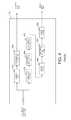
- FIG. 4shows a block diagram of a prior-art implementation of filter bank 101 that performs a functional equivalent of highpass filtering and downsampling operations using a series of interpolation, resampling, decimation, and other operations.
- lowpass filter 401 and downsampler 402serve to generate the lowband speech signal
- interpolator 403 , resampler 404 , decimater 405 , spectral reversal circuitry 406 , decimator 407 , and spectral shaping circuitry 408server to generate highband speech signals.
- Such an implementationmay be easier to design and/or may allow reuse of functional blocks of logic and/or code.
- the same functional blockmay be used to perform the operations of decimation by 2 ⁇ 5 to 12.8 kHz ( 402 ) and decimation by 5/11 to 16 kHz ( 407 ) as shown in FIG. 4 .
- the spectral reversal operationmay be implemented by multiplying the signal with the function e jn ⁇ or the sequence ( ⁇ 1)n, whose values alternate between ⁇ 1 and ⁇ 1.
- the spectral shaping operationmay be implemented as a lowpass filter configured to shape the signal to obtain a desired overall filter response.
- highband excitation generatoras described herein may be configured to produce a highband excitation signal that also has a spectrally reversed form.
- the highest sample rate in the above implementationis 64 kHz and the number of processing steps required to obtain a critically sampled version of the highband speech signal is six, indicating a relatively high degree of complexity before encoding may commence.
- the flexibility of this approachis limited because of the need to achieve a critically sampled version of the highband speech signal, i.e. a sample rate which corresponds to precisely twice the upper frequency of the band to be coded. In this case the required sampling rate is 28.8 kHz to code the highband with an upper frequency of 14.4 kHz. Therefore a need exists for a method and apparatus for encoding signals that reduces the complexity with the above described encoder and enhances flexibility to code different highband configurations.
- FIG. 1is a block diagram of a prior-art encoder.
- FIG. 2illustrates wideband speech and its lowband and highband components.
- FIG. 3illustrates wideband speech and its lowband and highband components.
- FIG. 4is a block diagram of a prior art filter bank for the encoder of FIG. 1 .
- FIG. 5is a block diagram of a filter bank.
- FIG. 6is a block diagram of the downmixer of FIG. 5 .
- FIG. 7illustrates filtering with the filter bank of FIG. 5 .
- FIG. 8is a block diagram of a prior-art decoder.
- FIG. 9is a block diagram of decoder.
- FIG. 10illustrates decoding with the decoder of FIG. 9 .
- FIG. 11is a flow chart showing operation of an encoder.
- FIG. 12is a flow chart showing operation of a filter bank.
- FIG. 13is a flow chart showing the operation of a downmixer.
- FIG. 14is a flow chart showing the operation of the highband filter of FIG. 9 .
- FIG. 15is an alternative block diagram of a filter bank
- FIG. 16illustrates filtering with the filter bank of FIG. 15
- references to specific implementation embodiments such as “circuitry”may equally be accomplished via either on general purpose computing apparatus (e.g., CPU) or specialized processing apparatus (e.g., DSP) executing software instructions stored in non-transitory computer-readable memory.
- general purpose computing apparatuse.g., CPU
- specialized processing apparatuse.g., DSP
- DSPdigital signal processor
- a method and apparatus for encoding a signalis provided herein.
- a wideband signal that is to be encodedenters a filter bank.
- a highband signal and a lowband signalare output from the filter bank.
- Each signalis separately encoded.
- a downmixing operationis implemented after spectral reversal, and prior to decimating.
- the downmixing operationgreatly reduces system complexity. In fact, it will be observed that the highest sample rate in the prior-art implementation is 64 kHz whereas the sample rate in the system described above remains at 32 kHz or below. This represents a significant complexity saving, as do the reduced number of processing blocks.
- the present inventionencompasses a method for encoding a signal.
- the methodcomprises the steps of receiving a wideband signal at a filter bank, filtering the wideband signal to produce a lowband signal and a highband signal, encoding the lowband signal with a narrowband encoder, and encoding the highband signal with a highband encoder.
- the step of filtering the wideband signal to produce the highband signalcomprises the steps of spectrally reversing the wideband signal to produce a spectrally-reversed signal and downmixing the spectrally-reversed signal to produce a down mixed signal.
- the present inventionadditionally encompasses a method for decoding a signal.
- the methodcomprises the steps of decoding a first signal with a narrowband decoder to produce a lowband signal, decoding a second signal with a highband decoder to produce highband signal, and combining the lowband and the highband signals.
- the step of combining the lowband and the highband signalscomprises the steps of spectrally reversing the highband signal, downmixing the spectrally-reversed signal, and adding the down mixed signal with a narrowband speech signal.
- the present inventionadditionally encompasses an apparatus comprising a filter bank receiving a wideband signal and outputting a lowband signal and a highband signal, a narrowband encoder encoding the lowband signal, and a highband encoder encoding the highband signal.
- the filter bankcomprises spectral reversal circuitry spectrally reversing the wideband signal to produce a spectrally-reversed signal, downmixing circuitry downmixing the spectrally-reversed signal to produce a down mixed signal.
- the present inventionadditionally encompasses an apparatus comprising a first decoder decoding a first signal to produce a lowband signal, a second decoder decoding a second signal to produce highband signal, spectral reversal circuitry spectrally reversing the highband signal to produce a spectrally-reversed signal, downmixing circuitry downmixing the spectrally-reversed signal to produce a down mixed signal, and an adder adding the down mixed signal with a narrowband speech signal.
- FIG. 5is a block diagram of a filter bank.
- the filter of FIG. 5comprises downmixing circuitry 501 .
- Preprocessing prior to dowmixingtakes downmixing takes place by spectral reversing circuitry 406 .
- Downmixing circuitry 501serves to downmix the pre-processed (i.e., a spectrally reversed) signal output from spectral reversal circuitry 406 . More particularly, during downmixing a signal is shifted in frequency by a predetermined amount.
- FIG. 6A more-detailed block diagram of downmixer 501 is shown in FIG. 6 .
- downmixer 501comprises Hilbert transform circuitry 601 , mixers 602 and 603 , sine/cosine generator 604 , and summing circuitry 605 .
- Downmixingfor example, of a 1600 Hz signal is accomplished by represented the pre-processed input signal at 32 kHz as a sine wave of exactly 20 samples period.
- circuitry 601with a Hilbert Transformer which is an all-pass filter with phase response equal to a ⁇ /2 shift for all frequencies applied to the input signal only to derive the Imaginary output (Im).
- ImImaginary output
- H r ⁇ ( z )z - 1 ⁇ ( 0.409203611 - 2.149822809 ⁇ z - 2 + 4.070339174 ⁇ z - 4 - 3.329716205 ⁇ z - 6 + z - 8 ) ( 1.0 + 3.329716205 ⁇ z - 2 - 4.070339174 ⁇ z - 4 + 2.149822809 ⁇ z - 6 - 0.409203611 ⁇ z - 8 )
- H i ⁇ ( z )( 0.111039799 - 1.067487518 ⁇ fz - 2 + 2.787298979 ⁇ z - 4 - 2.830736288 ⁇ z - 6 + z - 8 ) ( 1.0 + 2.830736288 ⁇ z - 2 - 2.787298979 ⁇ z - 4 + 1.067487518 ⁇ z - 6 - 0.1110397
- each of the filtershave numerators and denominators of order 8, only even powers of z are non-zero and therefore the filters only require a total of 8 multiply-accumulates per sample. It is also evident that they have all-pass characteristics since the magnitudes of the numerator and denominator coefficients are time reversals of one another.
- quadrature versions of a ⁇ 1600 Hz tone signalIn order to downmix these two quadrature versions of the signal by 1600 Hz, quadrature versions of a ⁇ 1600 Hz tone signal, sampled at the same sample rate, must be complex multiplied by the quadrature input signal samples. This is accomplished by mixers 602 and 603 .
- the mixed toneis of the form e ⁇ jT 2 ⁇ f/f s where T is a sample index, f is the frequency translation in Hz and f s is the sample rate in Hz. Therefore for 1600 Hz sampled at 32 kHz is of the form e ⁇ jT 2 ⁇ 1600/32000 .
- the ⁇ 1600 Hz quadrature tone signal sampled at 32 kHzrequires just 25 words of storage in table 604 since the cosine and sine values overlap as shown below and repeat every 20 samples.
- the operations of a spectral-flip followed by 1600 Hz downmixrepresent a useful processing block. Particularly since this combination of operations are self-inverse for band-limited signals.
- the resulting signalsare summed by summer 605 and output to decimator 407 .
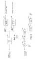
- FIG. 7illustrates filtering with the filter bank of FIG. 5 .
- the input signal 701is fed into preprocessing circuitry, which in this case comprises spectral reversal circuitry 406 .
- Circuitry 406comprises a 32 kHz sampled signal occupying a bandwidth of 14.4 kHz with a highband component and a lowband component (sometimes referred to as a narrowband component).
- the resulting signalexists between 1.6 kHz and 16 kHz, with the highband component lower in frequency than the lowband component.
- the lowband componentmay be filtered off ( 703 ) via a filter (not shown in FIG. 6 ).
- the resulting highband componentis shifted in frequency by 1600 Hz ( 704 ).
- the 16 kHz signalis decimated by 2 via decimator 407 , resulting in signal 705 .
- FIG. 8is a block diagram of a prior-art decoder.
- the decoder of FIG. 8comprises both narrowband decoder 802 and highband decoder 803 .
- filter bank 801is provided to properly combine the lowband and highband signals.
- complexity issuesexist with the prior-art filter banks.
- the filter described aboveis provided. This is illustrated in FIG. 9 .
- downmixer 902is provided. Downmixer 902 is similar to the downmixer described above, with its operation being described in FIG. 10 .
- FIG. 10illustrates decoding with the decoder of FIG. 9 .
- input signal 1001enters interpolator 904 where an interpolation takes place, expanding it in frequency. This is shown as signal 1002 .
- Spectral flip circuitry 903flips (reverses) the resulting signal to produce flipped signal 1003 (preprocessed signal).
- Downmixer 902then shifts the highband portion of signal 1003 by a predetermined amount to produce signal 1004 .
- the lowband signalis added by adder 901 resulting in signal 1005 .
- the steps of spectral flip and 1600 Hz downmixare employed in both the encoding process to derive the target signal in the encoder and in the decoder during the conversion of the critically sampled highband signal to the 32 kHz sampled synthetic speech at the output of the decoder.
- the order of the processing steps of spectral flipping and Hilbert transformation/linear frequency translationmay be interchanged.
- FIG. 11is a flow chart showing operation of an encoder.
- the logic flowbegins at step 1101 where a wideband signal (e.g., wideband speech) is received by filter bank 500 .
- filter bank 500filters the wideband signal to produce a lowband and a highband signal.
- the lowband signalis then encoded by narrowband encoder (step 1105 ) while the highband portion of the wideband signal is encoded by a highband encoder (step 1107 ).
- FIG. 12is a flow chart showing operation of a filter bank. In particular, FIG. 12 shows those steps performed at block 1103 for producing a highband signal.
- the logic flowbegins at step 1201 where spectral reversal circuitry 406 performs a spectral reversal on the wideband signal.
- downmixer 501then down mixes the spectrally-reversed signal.
- the logic flowcontinues to step 1205 where the down mixed signal is then decimated by decimator 407 .
- Spectral shapingthen takes place on the resulting signal at step 1207 by circuitry 408 .
- the resulting signalis then output to a highband encoder (step 1209 ).
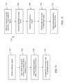
- FIG. 13is a flow chart showing the operation of downmixer 501 during step 1203 , above.
- the logic flowbegins at step 1301 where Hilbert Transform circuitry 601 performs a Hilbert transform on a preprocessed (e.g., spectrally-reversed) signal to produce two quadrature versions (real and imaginary) of the spectrally reversed signal.
- a preprocessede.g., spectrally-reversed
- the resulting real and imaginary signalsare mixed via mixers 602 and 603 with a cosine and sine function, respectively.
- the mixed signalsare added via circuitry 605 .
- the resulting signalis then output to decimator 407 .
- FIG. 14is a flow chart showing the operation of the highband filter of FIG. 9 .
- the logic flowbegins at step 1401 where spectral shaping is performed on a highband speech signal received from a highband encoder. This is accomplished via circuitry 905 .
- circuitry 904interpolates the spectrally-shaped signal.
- the resulting signalis spectrally reversed by circuitry 903 .
- the resulting signalis then sent to downmixer 902 where downmixing occurs (step 1407 ).
- the lowband signalis then added via adder 901 to the down mixed signal at step 1409 . It should be noted that the step of downmixing occurs as illustrated in FIG. 13 .
- FIG. 15is a block diagram of an alternative embodiment of the filter bank.
- the filter of FIG. 15comprises downmixing circuitry 1502 .
- downmixing circuitry 1502serves to downmix a highpass filtered version of the input signal; filtered by filter 1501 .
- the preprocessing of the signal that is fed into downmixer 1502comprises high-pass filtering.
- FIG. 16illustrates filtering with the filter bank of FIG. 15 .
- the input signal 701 into highpass filter 1501comprises a 32 kHz sampled signal occupying a bandwidth of 14.4 kHz with a highband component and a lowband component (sometimes referred to as a narrowband component).
- the resulting signalexists between 6.4 kHz and 14.4 kHz.
- the resulting highband componentis shifted in frequency by 6400 Hz ( 1603 ).
- the 16 kHz signalis decimated by 2 via decimator 407 , resulting in signal 1604 .
Landscapes
- Engineering & Computer Science (AREA)
- Physics & Mathematics (AREA)
- Computational Linguistics (AREA)
- Signal Processing (AREA)
- Health & Medical Sciences (AREA)
- Audiology, Speech & Language Pathology (AREA)
- Human Computer Interaction (AREA)
- Acoustics & Sound (AREA)
- Multimedia (AREA)
- Spectroscopy & Molecular Physics (AREA)
- Quality & Reliability (AREA)
- Compression, Expansion, Code Conversion, And Decoders (AREA)
Abstract
Description
These two filters, when applied to an input signal, will yield two quadrature versions of that input signal (real (Re) and imaginary (Im)). It will be observed that although each of the filters have numerators and denominators of
| cos(0) | = 1.0 | |||
| cos(π/10) | = 0.951056516 | |||
| cos(π/5) | = 0.809016994 | |||
| cos(3π/10) | = 0.587785252 | |||
| cos(2π/5) | = 0.309016994 | |||
| cos(π/2) | = −sin(0) | = 0.0 | ||
| cos(3π/5) | = −sin(π/10) | = −0.309016994 | ||
| cos(7π/10) | = −sin(π/5) | = −0.587785252 | ||
| cos(4π/5) | = −sin(3π/10) | = −0.809016994 | ||
| cos(9π/10) | = −sin(2π/5) | = −0.951056516 | ||
| cos(π) | = −sin(π/2) | = −1.0 | ||
| cos(11π/10) | = −sin(3π/5) | = −0.951056516 | ||
| cos(6π/5) | = −sin(7π/10) | = −0.809016994 | ||
| cos(13π/10) | = −sin(4π/5) | = −0.587785252 | ||
| cos(7π/5) | = −sin(9π/10) | = −0.309016994 | ||
| cos(3π/2) | = −sin(π) | = 0.0 | ||
| cos(8π/5) | = −sin(11π/10) | = 0.309016994 | ||
| cos(17π/10) | = −sin(6π/5) | = 0.587785252 | ||
| cos(9π/5) | = −sin(13π/10) | = 0.809016994 | ||
| cos(19π/10) | = −sin(7π/5) | = 0.951056516 | ||
| −sin(3π/2) | = 1.0 | |||
| −sin(8π/5) | = 0.951056516 | |||
| −sin(17π/10) | = 0.809016994 | |||
| −sin(9π/5) | = 0.587785252 | |||
| −sin(19π/10) | = 0.309016994 | |||
Only the real samples of this complex multiplication are required for storage which reduces the complex multiplication to the following;
output[i]=inputReal[i]·cos_table[j]+inputImage[i]·sine_table[j]
where the sample counter j is equal to counter i modulo 20 (i % 20).
In the context of generating the high band component of a super wideband signal using a 12.8 kHz sampled core, the operations of a spectral-flip followed by 1600 Hz downmix represent a useful processing block. Particularly since this combination of operations are self-inverse for band-limited signals. The resulting signals are summed by
Claims (17)
Priority Applications (8)
| Application Number | Priority Date | Filing Date | Title |
|---|---|---|---|
| US13/157,371US9070361B2 (en) | 2011-06-10 | 2011-06-10 | Method and apparatus for encoding a wideband speech signal utilizing downmixing of a highband component |
| PCT/US2012/040844WO2012170385A1 (en) | 2011-06-10 | 2012-06-05 | Method and apparatus for encoding a signal |
| MX2013014493AMX2013014493A (en) | 2011-06-10 | 2012-06-05 | Method and apparatus for encoding a signal. |
| CN201280028814.5ACN103608860B (en) | 2011-06-10 | 2012-06-05 | The method and apparatus that signal is encoded |
| BR112013031796-5ABR112013031796B1 (en) | 2011-06-10 | 2012-06-05 | method and equipment for encoding a signal |
| CA2838201ACA2838201C (en) | 2011-06-10 | 2012-06-05 | Method and apparatus for encoding a signal |
| KR1020137032837AKR101613345B1 (en) | 2011-06-10 | 2012-06-05 | Method and apparatus for encoding a signal |
| EP12727043.7AEP2718926B1 (en) | 2011-06-10 | 2012-06-05 | Methods and apparatuses for encoding and decoding a signal |
Applications Claiming Priority (1)
| Application Number | Priority Date | Filing Date | Title |
|---|---|---|---|
| US13/157,371US9070361B2 (en) | 2011-06-10 | 2011-06-10 | Method and apparatus for encoding a wideband speech signal utilizing downmixing of a highband component |
Publications (2)
| Publication Number | Publication Date |
|---|---|
| US20120316885A1 US20120316885A1 (en) | 2012-12-13 |
| US9070361B2true US9070361B2 (en) | 2015-06-30 |
Family
ID=46246278
Family Applications (1)
| Application Number | Title | Priority Date | Filing Date |
|---|---|---|---|
| US13/157,371Active2034-02-11US9070361B2 (en) | 2011-06-10 | 2011-06-10 | Method and apparatus for encoding a wideband speech signal utilizing downmixing of a highband component |
Country Status (8)
| Country | Link |
|---|---|
| US (1) | US9070361B2 (en) |
| EP (1) | EP2718926B1 (en) |
| KR (1) | KR101613345B1 (en) |
| CN (1) | CN103608860B (en) |
| BR (1) | BR112013031796B1 (en) |
| CA (1) | CA2838201C (en) |
| MX (1) | MX2013014493A (en) |
| WO (1) | WO2012170385A1 (en) |
Families Citing this family (8)
| Publication number | Priority date | Publication date | Assignee | Title |
|---|---|---|---|---|
| JP6179122B2 (en)* | 2013-02-20 | 2017-08-16 | 富士通株式会社 | Audio encoding apparatus, audio encoding method, and audio encoding program |
| EP2830052A1 (en) | 2013-07-22 | 2015-01-28 | Fraunhofer-Gesellschaft zur Förderung der angewandten Forschung e.V. | Audio decoder, audio encoder, method for providing at least four audio channel signals on the basis of an encoded representation, method for providing an encoded representation on the basis of at least four audio channel signals and computer program using a bandwidth extension |
| US10083708B2 (en) | 2013-10-11 | 2018-09-25 | Qualcomm Incorporated | Estimation of mixing factors to generate high-band excitation signal |
| US10803877B2 (en) | 2015-09-04 | 2020-10-13 | Samsung Electronics Co., Ltd. | Signal processing methods and apparatuses for enhancing sound quality |
| US10573326B2 (en)* | 2017-04-05 | 2020-02-25 | Qualcomm Incorporated | Inter-channel bandwidth extension |
| HUE070149T2 (en)* | 2018-12-03 | 2025-05-28 | Dolby Laboratories Licensing Corp | Interpolation of reshaping functions |
| BR112022002100A2 (en)* | 2019-08-08 | 2022-04-12 | Boomcloud 360 Inc | Adaptable non-linear filter banks for psychoacoustic frequency range extension |
| US11838732B2 (en) | 2021-07-15 | 2023-12-05 | Boomcloud 360 Inc. | Adaptive filterbanks using scale-dependent nonlinearity for psychoacoustic frequency range extension |
Citations (18)
| Publication number | Priority date | Publication date | Assignee | Title |
|---|---|---|---|---|
| US5818212A (en) | 1990-11-30 | 1998-10-06 | Samsung Electronics Co., Ltd. | Reference voltage generating circuit of a semiconductor memory device |
| US6104822A (en)* | 1995-10-10 | 2000-08-15 | Audiologic, Inc. | Digital signal processing hearing aid |
| US6182031B1 (en)* | 1998-09-15 | 2001-01-30 | Intel Corp. | Scalable audio coding system |
| WO2001050458A1 (en) | 1999-12-31 | 2001-07-12 | Thomson Licensing S.A. | Subband adpcm voice encoding and decoding |
| US6732070B1 (en)* | 2000-02-16 | 2004-05-04 | Nokia Mobile Phones, Ltd. | Wideband speech codec using a higher sampling rate in analysis and synthesis filtering than in excitation searching |
| US20040125878A1 (en)* | 1997-06-10 | 2004-07-01 | Coding Technologies Sweden Ab | Source coding enhancement using spectral-band replication |
| US6947509B1 (en) | 1999-11-30 | 2005-09-20 | Verance Corporation | Oversampled filter bank for subband processing |
| US20050276335A1 (en)* | 2004-06-09 | 2005-12-15 | Rajendra Kumar | Generalized polyphase channelization system |
| US20060277038A1 (en)* | 2005-04-01 | 2006-12-07 | Qualcomm Incorporated | Systems, methods, and apparatus for highband excitation generation |
| US20080140393A1 (en) | 2006-12-08 | 2008-06-12 | Electronics & Telecommunications Research Institute | Speech coding apparatus and method |
| US20080263285A1 (en)* | 2007-04-20 | 2008-10-23 | Siport, Inc. | Processor extensions for accelerating spectral band replication |
| US20080298517A1 (en)* | 2007-06-04 | 2008-12-04 | Seiichi Izumi | Receiving apparatus, program and receiving method |
| WO2009063728A1 (en) | 2007-11-15 | 2009-05-22 | National Institute Of Advanced Industrial Science And Technology | Frequency conversion device |
| CN101868821A (en) | 2007-11-21 | 2010-10-20 | Lg电子株式会社 | The method and apparatus that is used for processing signals |
| US20110057818A1 (en)* | 2006-01-18 | 2011-03-10 | Lg Electronics, Inc. | Apparatus and Method for Encoding and Decoding Signal |
| US20110295598A1 (en)* | 2010-06-01 | 2011-12-01 | Qualcomm Incorporated | Systems, methods, apparatus, and computer program products for wideband speech coding |
| US20120226496A1 (en)* | 2009-11-12 | 2012-09-06 | Lg Electronics Inc. | apparatus for processing a signal and method thereof |
| US20120275607A1 (en)* | 2009-12-16 | 2012-11-01 | Dolby International Ab | Sbr bitstream parameter downmix |
Family Cites Families (3)
| Publication number | Priority date | Publication date | Assignee | Title |
|---|---|---|---|---|
| TW321810B (en)* | 1995-10-26 | 1997-12-01 | Sony Co Ltd | |
| JP2005509928A (en)* | 2001-11-23 | 2005-04-14 | コーニンクレッカ フィリップス エレクトロニクス エヌ ヴィ | Audio signal bandwidth expansion |
| UA95776C2 (en)* | 2005-04-01 | 2011-09-12 | Квелкомм Инкорпорейтед | System, method and device for generation of excitation in high-frequency range |
- 2011
- 2011-06-10USUS13/157,371patent/US9070361B2/enactiveActive
- 2012
- 2012-06-05MXMX2013014493Apatent/MX2013014493A/enactiveIP Right Grant
- 2012-06-05WOPCT/US2012/040844patent/WO2012170385A1/enactiveApplication Filing
- 2012-06-05KRKR1020137032837Apatent/KR101613345B1/enactiveActive
- 2012-06-05EPEP12727043.7Apatent/EP2718926B1/enactiveActive
- 2012-06-05BRBR112013031796-5Apatent/BR112013031796B1/enactiveIP Right Grant
- 2012-06-05CACA2838201Apatent/CA2838201C/enactiveActive
- 2012-06-05CNCN201280028814.5Apatent/CN103608860B/enactiveActive
Patent Citations (22)
| Publication number | Priority date | Publication date | Assignee | Title |
|---|---|---|---|---|
| US5818212A (en) | 1990-11-30 | 1998-10-06 | Samsung Electronics Co., Ltd. | Reference voltage generating circuit of a semiconductor memory device |
| US6104822A (en)* | 1995-10-10 | 2000-08-15 | Audiologic, Inc. | Digital signal processing hearing aid |
| US7328162B2 (en) | 1997-06-10 | 2008-02-05 | Coding Technologies Ab | Source coding enhancement using spectral-band replication |
| US20040125878A1 (en)* | 1997-06-10 | 2004-07-01 | Coding Technologies Sweden Ab | Source coding enhancement using spectral-band replication |
| US6182031B1 (en)* | 1998-09-15 | 2001-01-30 | Intel Corp. | Scalable audio coding system |
| US6947509B1 (en) | 1999-11-30 | 2005-09-20 | Verance Corporation | Oversampled filter bank for subband processing |
| WO2001050458A1 (en) | 1999-12-31 | 2001-07-12 | Thomson Licensing S.A. | Subband adpcm voice encoding and decoding |
| US6732070B1 (en)* | 2000-02-16 | 2004-05-04 | Nokia Mobile Phones, Ltd. | Wideband speech codec using a higher sampling rate in analysis and synthesis filtering than in excitation searching |
| US20050276335A1 (en)* | 2004-06-09 | 2005-12-15 | Rajendra Kumar | Generalized polyphase channelization system |
| US20080126086A1 (en)* | 2005-04-01 | 2008-05-29 | Qualcomm Incorporated | Systems, methods, and apparatus for gain coding |
| US20060277038A1 (en)* | 2005-04-01 | 2006-12-07 | Qualcomm Incorporated | Systems, methods, and apparatus for highband excitation generation |
| US20110057818A1 (en)* | 2006-01-18 | 2011-03-10 | Lg Electronics, Inc. | Apparatus and Method for Encoding and Decoding Signal |
| US20080140393A1 (en) | 2006-12-08 | 2008-06-12 | Electronics & Telecommunications Research Institute | Speech coding apparatus and method |
| US20080263285A1 (en)* | 2007-04-20 | 2008-10-23 | Siport, Inc. | Processor extensions for accelerating spectral band replication |
| US20080298517A1 (en)* | 2007-06-04 | 2008-12-04 | Seiichi Izumi | Receiving apparatus, program and receiving method |
| WO2009063728A1 (en) | 2007-11-15 | 2009-05-22 | National Institute Of Advanced Industrial Science And Technology | Frequency conversion device |
| CN101868821A (en) | 2007-11-21 | 2010-10-20 | Lg电子株式会社 | The method and apparatus that is used for processing signals |
| US20100274557A1 (en)* | 2007-11-21 | 2010-10-28 | Hyen-O Oh | Method and an apparatus for processing a signal |
| US20100305956A1 (en) | 2007-11-21 | 2010-12-02 | Hyen-O Oh | Method and an apparatus for processing a signal |
| US20120226496A1 (en)* | 2009-11-12 | 2012-09-06 | Lg Electronics Inc. | apparatus for processing a signal and method thereof |
| US20120275607A1 (en)* | 2009-12-16 | 2012-11-01 | Dolby International Ab | Sbr bitstream parameter downmix |
| US20110295598A1 (en)* | 2010-06-01 | 2011-12-01 | Qualcomm Incorporated | Systems, methods, apparatus, and computer program products for wideband speech coding |
Non-Patent Citations (3)
| Title |
|---|
| Luo, et al. "Wideband audio over narrowband based on digital watermarking." Wireless Communications, Networking and Information Security (WCNIS), 2010 IEEE International Conference on. IEEE, Jun. 2010, pp. 697-701.* |
| Patent Cooperation Treaty, International Search Report and Written Opinion of the International Searching Authority for International Application No. PCT/US2012/040844, Aug. 23, 2012, 14 pages. |
| Qian, Yasheng et al: "Classified Highband Excitation for Bandwidth Extension of Telephony Signals", Proceedings of Eusipco2005, all pages. |
Also Published As
| Publication number | Publication date |
|---|---|
| US20120316885A1 (en) | 2012-12-13 |
| WO2012170385A1 (en) | 2012-12-13 |
| CA2838201A1 (en) | 2012-12-13 |
| EP2718926B1 (en) | 2017-09-13 |
| BR112013031796B1 (en) | 2021-03-09 |
| CN103608860A (en) | 2014-02-26 |
| EP2718926A1 (en) | 2014-04-16 |
| CN103608860B (en) | 2016-06-22 |
| KR20140009560A (en) | 2014-01-22 |
| KR101613345B1 (en) | 2016-04-18 |
| BR112013031796A2 (en) | 2016-12-20 |
| MX2013014493A (en) | 2014-03-27 |
| CA2838201C (en) | 2016-10-18 |
Similar Documents
| Publication | Publication Date | Title |
|---|---|---|
| US9070361B2 (en) | Method and apparatus for encoding a wideband speech signal utilizing downmixing of a highband component | |
| JP5722437B2 (en) | Method, apparatus, and computer readable storage medium for wideband speech coding | |
| CN101184979B (en) | Systems, methods and devices for high frequency band excitation generation | |
| JP5437067B2 (en) | System and method for including an identifier in a packet associated with a voice signal | |
| US11594236B2 (en) | Audio encoding/decoding based on an efficient representation of auto-regressive coefficients | |
| EP2628156B1 (en) | Audio signal bandwidth extension in celp-based speech coder | |
| NO340434B1 (en) | Høybåndeksiteringsgenerator | |
| EP1111589A1 (en) | Wideband speech coding with parametric coding of high frequency component | |
| CN103366751B (en) | A kind of sound codec devices and methods therefor | |
| CN103155035B (en) | Audio signal bandwidth extension in CELP-based speech coder | |
| US9236058B2 (en) | Systems and methods for quantizing and dequantizing phase information | |
| EP4553830A1 (en) | Audio processor for extended the audio bandwidth of band-limited audio signal | |
| US7848923B2 (en) | Method for reducing decoder complexity in waveform interpolation speech decoding by converting dimension of vector | |
| WO2025099288A1 (en) | Audio processor with a steered audio bandwidth extension | |
| HK1114940A (en) | Method and apparatus for split-band encoding of speech signals |
Legal Events
| Date | Code | Title | Description |
|---|---|---|---|
| AS | Assignment | Owner name:MOTOROLA MOBILITY, INC., ILLINOIS Free format text:ASSIGNMENT OF ASSIGNORS INTEREST;ASSIGNOR:GIBBS, JONATHAN A.;REEL/FRAME:026422/0229 Effective date:20110610 | |
| AS | Assignment | Owner name:MOTOROLA MOBILITY LLC, ILLINOIS Free format text:CHANGE OF NAME;ASSIGNOR:MOTOROLA MOBILITY, INC.;REEL/FRAME:028441/0265 Effective date:20120622 | |
| AS | Assignment | Owner name:GOOGLE TECHNOLOGY HOLDINGS LLC, CALIFORNIA Free format text:ASSIGNMENT OF ASSIGNORS INTEREST;ASSIGNOR:MOTOROLA MOBILITY LLC;REEL/FRAME:034286/0001 Effective date:20141028 | |
| AS | Assignment | Owner name:GOOGLE TECHNOLOGY HOLDINGS LLC, CALIFORNIA Free format text:CORRECTIVE ASSIGNMENT TO CORRECT THE REMOVE INCORRECT PATENT NO. 8577046 AND REPLACE WITH CORRECT PATENT NO. 8577045 PREVIOUSLY RECORDED ON REEL 034286 FRAME 0001. ASSIGNOR(S) HEREBY CONFIRMS THE ASSIGNMENT;ASSIGNOR:MOTOROLA MOBILITY LLC;REEL/FRAME:034538/0001 Effective date:20141028 | |
| STCF | Information on status: patent grant | Free format text:PATENTED CASE | |
| MAFP | Maintenance fee payment | Free format text:PAYMENT OF MAINTENANCE FEE, 4TH YEAR, LARGE ENTITY (ORIGINAL EVENT CODE: M1551); ENTITY STATUS OF PATENT OWNER: LARGE ENTITY Year of fee payment:4 | |
| MAFP | Maintenance fee payment | Free format text:PAYMENT OF MAINTENANCE FEE, 8TH YEAR, LARGE ENTITY (ORIGINAL EVENT CODE: M1552); ENTITY STATUS OF PATENT OWNER: LARGE ENTITY Year of fee payment:8 |