US9070214B1 - Systems and methods for data and model-driven image reconstruction and enhancement - Google Patents
Systems and methods for data and model-driven image reconstruction and enhancementDownload PDFInfo
- Publication number
- US9070214B1 US9070214B1US14/310,746US201414310746AUS9070214B1US 9070214 B1US9070214 B1US 9070214B1US 201414310746 AUS201414310746 AUS 201414310746AUS 9070214 B1US9070214 B1US 9070214B1
- Authority
- US
- United States
- Prior art keywords
- image
- anatomy
- images
- reconstruction
- enhancement
- Prior art date
- Legal status (The legal status is an assumption and is not a legal conclusion. Google has not performed a legal analysis and makes no representation as to the accuracy of the status listed.)
- Active
Links
Images


Classifications
- G—PHYSICS
- G06—COMPUTING OR CALCULATING; COUNTING
- G06T—IMAGE DATA PROCESSING OR GENERATION, IN GENERAL
- G06T11/00—2D [Two Dimensional] image generation
- G06T11/003—Reconstruction from projections, e.g. tomography
- G06T11/006—Inverse problem, transformation from projection-space into object-space, e.g. transform methods, back-projection, algebraic methods
- A—HUMAN NECESSITIES
- A61—MEDICAL OR VETERINARY SCIENCE; HYGIENE
- A61B—DIAGNOSIS; SURGERY; IDENTIFICATION
- A61B6/00—Apparatus or devices for radiation diagnosis; Apparatus or devices for radiation diagnosis combined with radiation therapy equipment
- A61B6/52—Devices using data or image processing specially adapted for radiation diagnosis
- A61B6/5205—Devices using data or image processing specially adapted for radiation diagnosis involving processing of raw data to produce diagnostic data
- G—PHYSICS
- G06—COMPUTING OR CALCULATING; COUNTING
- G06F—ELECTRIC DIGITAL DATA PROCESSING
- G06F18/00—Pattern recognition
- G06F18/20—Analysing
- G06F18/22—Matching criteria, e.g. proximity measures
- G—PHYSICS
- G06—COMPUTING OR CALCULATING; COUNTING
- G06T—IMAGE DATA PROCESSING OR GENERATION, IN GENERAL
- G06T11/00—2D [Two Dimensional] image generation
- G06T11/003—Reconstruction from projections, e.g. tomography
- G—PHYSICS
- G06—COMPUTING OR CALCULATING; COUNTING
- G06T—IMAGE DATA PROCESSING OR GENERATION, IN GENERAL
- G06T11/00—2D [Two Dimensional] image generation
- G06T11/003—Reconstruction from projections, e.g. tomography
- G06T11/005—Specific pre-processing for tomographic reconstruction, e.g. calibration, source positioning, rebinning, scatter correction, retrospective gating
- G06T5/001—
- G—PHYSICS
- G06—COMPUTING OR CALCULATING; COUNTING
- G06T—IMAGE DATA PROCESSING OR GENERATION, IN GENERAL
- G06T5/00—Image enhancement or restoration
- G06T5/50—Image enhancement or restoration using two or more images, e.g. averaging or subtraction
- G—PHYSICS
- G06—COMPUTING OR CALCULATING; COUNTING
- G06T—IMAGE DATA PROCESSING OR GENERATION, IN GENERAL
- G06T7/00—Image analysis
- G06T7/0002—Inspection of images, e.g. flaw detection
- G06T7/0012—Biomedical image inspection
- G—PHYSICS
- G06—COMPUTING OR CALCULATING; COUNTING
- G06T—IMAGE DATA PROCESSING OR GENERATION, IN GENERAL
- G06T7/00—Image analysis
- G06T7/0002—Inspection of images, e.g. flaw detection
- G06T7/0012—Biomedical image inspection
- G06T7/0014—Biomedical image inspection using an image reference approach
- G—PHYSICS
- G06—COMPUTING OR CALCULATING; COUNTING
- G06T—IMAGE DATA PROCESSING OR GENERATION, IN GENERAL
- G06T2207/00—Indexing scheme for image analysis or image enhancement
- G06T2207/10—Image acquisition modality
- G06T2207/10072—Tomographic images
- G—PHYSICS
- G06—COMPUTING OR CALCULATING; COUNTING
- G06T—IMAGE DATA PROCESSING OR GENERATION, IN GENERAL
- G06T2207/00—Indexing scheme for image analysis or image enhancement
- G06T2207/20—Special algorithmic details
- G06T2207/20081—Training; Learning
- G—PHYSICS
- G06—COMPUTING OR CALCULATING; COUNTING
- G06T—IMAGE DATA PROCESSING OR GENERATION, IN GENERAL
- G06T2207/00—Indexing scheme for image analysis or image enhancement
- G06T2207/30—Subject of image; Context of image processing
- G06T2207/30004—Biomedical image processing
- G—PHYSICS
- G06—COMPUTING OR CALCULATING; COUNTING
- G06T—IMAGE DATA PROCESSING OR GENERATION, IN GENERAL
- G06T2207/00—Indexing scheme for image analysis or image enhancement
- G06T2207/30—Subject of image; Context of image processing
- G06T2207/30004—Biomedical image processing
- G06T2207/30101—Blood vessel; Artery; Vein; Vascular
- G—PHYSICS
- G06—COMPUTING OR CALCULATING; COUNTING
- G06T—IMAGE DATA PROCESSING OR GENERATION, IN GENERAL
- G06T2211/00—Image generation
- G06T2211/40—Computed tomography
- G06T2211/404—Angiography
- G—PHYSICS
- G06—COMPUTING OR CALCULATING; COUNTING
- G06T—IMAGE DATA PROCESSING OR GENERATION, IN GENERAL
- G06T2211/00—Image generation
- G06T2211/40—Computed tomography
- G06T2211/424—Iterative
- G—PHYSICS
- G06—COMPUTING OR CALCULATING; COUNTING
- G06T—IMAGE DATA PROCESSING OR GENERATION, IN GENERAL
- G06T2211/00—Image generation
- G06T2211/40—Computed tomography
- G06T2211/436—Limited angle
Definitions
- Various embodiments of the present disclosurerelate generally to medical imaging and related methods. More specifically, particular embodiments of the present disclosure relate to systems and methods for data and model-driven image reconstruction and/or enhancement.
- Imaging and extraction of anatomy from imagingis important, as evidenced by the many means of medical imaging available.
- Several imaging techniquesinvolve reconstruction and image enhancement on raw acquired data in order to produce better images.
- Reconstruction and enhancementmay be used to decrease noise in an image, smooth the effects of incomplete data, and/or optimize imaging.
- Common forms of medical imaging that employ image reconstruction and/or enhancementinclude computed tomography (CT) scans, magnetic resonance imaging (MR), ultrasound, single positron emission computed tomography (SPECT), and positron emission tomography (PET).
- CTcomputed tomography
- MRmagnetic resonance imaging
- SPECTsingle positron emission computed tomography
- PETpositron emission tomography
- One mechanism used to achieve higher-quality reconstruction and enhancementis to use prior information about a target reconstructed/enhanced image. Typically, the prior information takes the form of assumptions about image smoothness or image patches from reference images.
- Reference imagesare often available and used to obtain the prior information.
- Reference imagesmay include at least a portion of a target anatomy, and portions of reference images may be used to render models of anatomy associated with the target anatomy.
- reference imagesmay be idealized images, images of a patient associated with a target anatomy (e.g., wherein a target anatomy may include an anatomical part of the patient), images of the anatomical part of other patients, etc.
- the imagesmay be collected at various times or conditions, and they may have various levels of relevance or resemblance to a specific target anatomy.
- reference images as image patchesmay mean that reference image use is piecemeal and/or may apply only to regions of an image identified as problematic. Evaluation of whether reference images are suitable for use as image patches may be lacking. In addition, use of reference images only as image patches may mean that unless portions of an image are identified as problematic, the image or various portions of the image may not have the opportunity to benefit from comparison to a reference image.
- One method of medical image reconstructionincludes: acquiring a plurality of images associated with a target anatomy; determining, using a processor, one or more associations between subdivisions of localized anatomy of the target anatomy identified from the plurality of images, and local image regions identified from the plurality of images; performing an initial image reconstruction based on image acquisition information of the target anatomy; and updating the initial image reconstruction or generating a new image reconstruction based on the image acquisition information and the one or more determined associations.
- a system for medical image reconstructioncomprises: a data storage device storing instructions for image reconstruction and enhancement; and a processor configured for: acquiring a plurality of images associated with a target anatomy; determining, using a processor, one or more associations between subdivisions of localized anatomy of the target anatomy identified from the plurality of images, and local image regions identified from the plurality of images; performing an initial image reconstruction based on image acquisition information of the target anatomy; and updating the initial image reconstruction or generating a new image reconstruction based on the image acquisition information and the one or more determined associations.
- a non-transitory computer readable mediumfor use on a computer system containing computer-executable programming instructions for medical image reconstruction.
- the methodincludes: acquiring a plurality of images associated with anatomy of a target anatomy; determining, using a processor, one or more associations between subdivisions of localized anatomy of the target anatomy identified from the plurality of images, and local image regions identified from the plurality of images; performing an initial image reconstruction based on image acquisition information of the target anatomy; and updating the initial image reconstruction or generating a new image reconstruction based on the image acquisition information and the one or more determined associations.
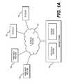
- FIG. 1Ais a block diagram of an exemplary system and network for image reconstruction and/or enhancement, according to an exemplary embodiment of the present disclosure.
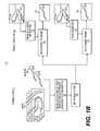
- FIG. 1Bis a block diagram of an exemplary overview of a training phase and production phase for image reconstruction and/or enhancement, according to an exemplary embodiment of the present disclosure.
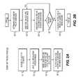
- FIG. 2Ais a block diagram of an exemplary method for a training phase of image reconstruction and/or enhancement, according to an exemplary embodiment of the present disclosure.
- FIG. 2Bis a block diagram of an exemplary method for building a model of image regions associated with a localized anatomy, for use in a training phase of reconstruction and/or enhancement of medical images, according to an exemplary embodiment of the present disclosure.
- FIG. 2Cis a block diagram of an exemplary method of a production phase of reconstruction of medical images, according to an exemplary embodiment of the present disclosure.
- FIG. 2Dis a block diagram of an exemplary method for producing a converged image reconstruction, for use in a production phase of reconstructing medical images, according to an exemplary embodiment of the present disclosure.
- FIG. 2Eis a block diagram of an exemplary method a production phase for producing an enhancement of medical images, according to an exemplary embodiment of the present disclosure.
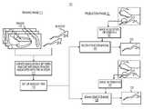
- FIG. 3A and FIG. 3Bare block diagrams of exemplary training methods for iterative reconstruction of images, according to an exemplary embodiment of the present disclosure.
- FIG. 4A and FIG. 4Bare block diagrams of exemplary methods for producing reconstructions, according to an exemplary embodiment of the present disclosure.
- the use of reference images as image patches for medical image reconstruction and/or enhancementmay involve using a portion of a reference image to compensate for deficits in a constructed image.
- the reference imagesmay have little or no impact on other parts of the constructed image.
- the present disclosureis directed to systems and methods for data and model-driven image reconstruction and enhancement using target anatomy reference images as more than image patches.
- the present disclosureis directed to improving image reconstruction and/or enhancement by incorporating into image reconstruction and/or enhancement, associations between anatomical subdivisions and image regions available from reference images.
- the present disclosureis directed to a new approach for reconstruction and/or enhancement of a target anatomy image using prior information about a target reconstructed/enhanced image, where the information includes associations between reference image regions and parts of the target anatomy, such as anatomical features extracted from or identified in the image regions.
- the present disclosuremay include both a training phase and a production (and/or usage phase) for use in a method of image reconstruction, as well as a method of enhancing images.
- the training phase for both image reconstruction and image enhancementmay include developing a set of known or knowable associations between anatomy and image renderings.
- the training phasemay involve receiving a collection of images, receiving or inputting information of an anatomical part or portion shown in each of the images (e.g., a localized anatomy for each of the images), and building a model of image regions associated with respective portions of the localized anatomy.
- An output from the training phasemay include a set of anatomical subdivisions associated with image regions.
- the production phase for reconstructionsmay include using the set of anatomical subdivisions associated with image regions (from the training phase) in conjunction with image acquisition information for a particular target anatomy, e.g., a particular patient or individual, in order to create a more accurate and/or better-informed image reconstruction.
- image reconstructionmay be based on acquired images and/or image acquisition information, and image enhancement may be based on any image information.
- the production phase for image enhancementmay then include using the set of anatomical subdivisions associated with image regions along with image information to output an enhanced image.
- FIG. 1Adepicts a block diagram of an exemplary environment of a system and network for data and model-driven image reconstruction and enhancement.
- FIG. 1Adepicts a plurality of physicians 102 and third party providers 104 , any of whom may be connected to an electronic network 100 , such as the Internet, through one or more computers, servers, and/or handheld mobile devices.
- Physicians 102 and/or third party providers 104may create or otherwise obtain images of one or more patients' cardiac, vascular, and/or organ systems.
- the physicians 102 and/or third party providers 104may also obtain any combination of patient-specific information, such as age, medical history, blood pressure, blood viscosity, etc.
- Physicians 102 and/or third party providers 104may transmit the cardiac/vascular/organ images and/or patient-specific information to server systems 106 over the electronic network 100 .
- Server systems 106may include storage devices for storing images and data received from physicians 102 and/or third party providers 104 .
- Server systems 106may also include processing devices for processing images and data stored in the storage devices.
- the data and model-driven image reconstruction and enhancement of the present disclosuremay be performed on a local processing device (e.g., a laptop), absent an external server or network.
- FIG. 1Bis a diagram of an overview 110 of an exemplary training phase and an exemplary production phase for image reconstruction and enhancement, according to an exemplary embodiment of the present disclosure.
- the systems and methods for image reconstruction and/or enhancementmay include a training phase 111 and a production phase 121 .
- the training phase 111may involve generating associations between anatomical subdivisions and image regions.
- the production phase 121may generally then use the associations to determine image priors for regions within a reconstruction or, in the case of an image enhancement, a previously provided image.
- the training phase 111may begin with receiving inputs of images 113 and known anatomy 115 .
- Images 113may include images from any known medical imaging modality (e.g., CT, MR, SPECT, etc.).
- Anatomy 115may be 2-D, 3-D, or other geometric models of human anatomy.
- images 113may include representations of anatomy 115 , and/or anatomy 115 may show or represent geometry of some portion of anatomy rendered in images 113 .
- anatomy 115may include models of anatomy, expected anatomy, etc. that are shown (or expected to be shown) in the images 113 .
- Models of common anatomy rendered between images 113 and anatomy 115 and/or a region of interest in both images 113 and anatomy 115may be referred to as “localized anatomy” within each of the images 113 .
- the associated images 113 and anatomy 115may be obtained from the same individual for whom images are to be reconstructed and/or enhanced in a production phase.
- one individual or patientmay be the source of multiple pairs or even all of the pairs of associated images 113 and anatomy 115 .
- each associated image 113 anatomy 115 pairmay be obtained from a different individual or patient.
- the training phase 111may then include step 117 of creating associations between portions of anatomy 115 and regions of images 113 .
- step 117may include identifying a region or subset of an image 113 , identifying a region or subset of a paired anatomy 115 , and associating the region or subset of the image 113 with the region or subset of the anatomy 115 .
- the training phase 111thus produces output 119 , which includes a set of associations between portions of anatomy 115 and regions of images 113 .
- Output 119may be used as an input to an exemplary production phase 121 , where reconstruction engine 123 and enhancement engine 125 may determine image priors based on output 119 for use in producing reconstructed and/or enhanced images of a particular individual or patient.
- reconstruction engine 123may receive image acquisition information 127 of an area of anatomy for a particular patient. Using image acquisition information 127 along with image priors determined from output 119 , reconstruction engine 123 may produce reconstruction 129 .
- enhancement engine 125may receive image information 131 . Enhancement engine 125 may then produce image enhancement 133 based on image information 131 and image enhancements determined from output 119 .
- FIGS. 2A and 2Bdepict flowcharts of exemplary embodiments of the training phase 111 of FIG. 1B .
- FIGS. 2C-2Edepict flowcharts of exemplary production phases for image reconstruction and image enhancement.
- FIGS. 3A and 3Bdepict flowcharts of exemplary embodiments of training phases as applied to cardiac and abdominal images, respectively.
- FIGS. 4A and 4Bdepict flowcharts of exemplary embodiments of production phases for cardiac and abdominal images, respectively, in which the training phase from FIG. 3A may provide an input for the production phase of FIG. 4A , and the training phase of FIG. 3B may be associated with the production phase of FIG. 4B .
- FIG. 2Ais a block diagram of an exemplary training phase for producing a model of image regions associated with anatomy portions for both reconstruction and enhancement of medical images, according to an exemplary embodiment.
- the procedures for production in image reconstruction and production in image enhancementmay differ in some respects, the procedure for a training phase may, in some cases, be the same for both image reconstruction and image enhancement.
- a model of image regions relied upon for the reconstruction and enhancementmay be generated the same way.
- models of image regions for image reconstruction and enhancementmay both include, or be based on, a set of known or created associations between anatomical subdivisions and corresponding image regions.
- the set of associationsmay represent an understanding of an image region being a representation of a portion of an anatomy, and in some embodiments, an understanding of the identity of the person having that portion of the anatomy.
- the training phasemay develop a model of relationships between images and anatomy, based on a collection of images. In this way, a model of image regions developed from the training phase may form a basis of expected image regions in relation to portions of anatomy, thus providing guidance for image reconstruction and enhancement.
- FIG. 2Bdepicts an embodiment of certain steps of the method of FIG. 2A , including exemplary detailed steps for building a model of associations between image regions and anatomy, according to one embodiment.
- FIG. 2Cdepicts steps of an exemplary production phase for an image reconstruction, according to an exemplary embodiment.
- FIG. 2Ddepicts an embodiment of certain exemplary steps of the method of FIG. 2C , including certain steps that may be repeated until convergence in order to produce the image reconstruction output by the method of FIG. 2C .
- FIG. 2Eincludes a production phase for an image enhancement.
- the steps in FIG. 2Cmay be similar to those of the method of FIG. 2E , except that the steps for FIG. 2E may not necessarily be based on an acquired image. Rather, since FIG. 2E addresses image enhancement, an image may be already available and need not be acquired and/or created in an independent step.
- FIG. 2Ais a block diagram of an exemplary method 200 of a training phase for reconstruction or enhancement of medical images, according to an exemplary embodiment of the present disclosure.
- Method 200may be performed by server systems 106 , based on information, images, and data received from physicians 102 and/or third party providers 104 over electronic network 100 .
- the method of FIG. 2Amay include receiving a collection of images (step 201 ).
- the collection of imagesmay include or be associated with a target anatomy, for example, an anatomical feature of one or more individuals.
- a target anatomymay be any image and/or portion of an image that may undergo analysis and/or be used for analysis.
- the imagesmay be stored, input, and/or received on an electronic storage device.
- method 200may further include receiving or inputting, for each image of the collection, a localized anatomy model of anatomy reflected within the image (step 203 ).
- the localized anatomymay include a portion of an anatomy to be reviewed or analyzed.
- a target anatomymay include a patient's heart, where a localized anatomy may include a localized model of a coronary artery vessel tree.
- the localized anatomy within the imagemay be received on an electronic storage device.
- step 205may include building a model of image regions associated with portions of the localized anatomy.
- the modelmay be built using a computational device. Exemplary methods of building the model are further described in FIG. 2B .
- Given the modela set of associated anatomical subdivisions and image regions may be produced. Such a set of associated anatomical subdivisions and image regions may be output to an electronic storage device (step 207 ).
- FIG. 2Bis a block diagram of an exemplary method 220 for building a model of image regions associated with respective/corresponding portions of localized anatomy in a training phase for reconstruction or enhancement of medical images, according to an exemplary embodiment of the present disclosure.
- method 220is one way of carrying out step 205 of modeling associations between image regions and portions (e.g., subdivisions) of localized anatomy.
- Method 220may be performed by server systems 106 , based on information, images, and data received from physicians 102 and/or third party providers 104 over electronic network 100 .
- the model of image regionsmay be built using a computational device.
- step 221may include determining a size and/or type of subdivision for a target anatomy in the images.
- a subdivisionmay be a single component encompassing an entire localized anatomy. Alternately, subdivisions may be very small relative to the image.
- Step 221may include determining a level of granularity in the size of the subdivisions.
- the size of subdivisionsmay be static or dynamic. For example, step 221 may include adjusting sizes of subdivisions in view of image resolution, sensitivity, etc.
- method 220may further include step 223 of subdividing the localized anatomy into one or more subdivisions, for each image and localized anatomy in the collection (e.g., the collection of images received at step 201 ).
- the subdivisionsmay be uniform across the entire image and localized anatomy, throughout the collection. In another example, the subdivisions may vary, depending on a local region of the anatomy.
- step 225may include associating a local region of an image with the one or more subdivisions of the anatomy. In other words, regions of the images may not be directly identified as being associated with a localized anatomy or one or more subdivisions of the localized anatomy. Step 225 may create associations between the regions of images and the one or more subdivisions, such that the local regions of the images may be recognized as being associated with subdivisions that correspond to the same localized anatomy. In one embodiment, step 227 may include an option to determine whether another image is available in the collection of images (e.g., from step 201 ).
- step 223may include combining or integrating a set of the local regions of the image that are associated with the one or more subdivisions. In integrating the set, step 229 may build a model of image regions associated with respective portions of an anatomy.
- FIG. 2Cis a block diagram of an exemplary method 240 for producing a reconstruction of medical images, according to an exemplary embodiment of the present disclosure.
- Method 240may be performed by server systems 106 , based on information, images, and data received from physicians 102 and/or third party providers 104 over electronic network 100 .
- method 240may be based on output from the training phase, for example, method 200 (including method 220 ).
- method 240may include step 241 of receiving image acquisition information, for instance, on an electronic storage device.
- step 243may include performing an initial image reconstruction based on the acquisition information from step 241 .
- the reconstructionmay be performed using any reconstruction method known in the art.
- Step 245may include receiving a set of associated anatomical subdivisions and associated image regions (e.g., from step 207 of the method 200 of a training phase). The set of associated anatomical subdivisions and associated image regions may be received on an electronic storage device.
- a converged reconstructionmay be created using the initial reconstruction, in conjunction with the set of anatomical subdivisions and associated image regions (e.g., from step 245 ). Exemplary steps for creating the converged reconstruction may be found at FIG. 2D . Then, method 240 may further include outputting the converged image reconstruction, for example, to an electronic storage device and/or display (step 249 ).
- FIG. 2Dis a block diagram of an exemplary method 260 for producing the converged image reconstruction (e.g., of step 247 ), according to an exemplary embodiment of the present disclosure.
- the steps of method 260may be repeated until images converge, thus forming an image reconstruction (e.g., the converged reconstruction).
- Method 260may be performed by server systems 106 , based on information, images, and data received from physicians 102 and/or third party providers 104 over electronic network 100 .
- method 260 of FIG. 2Dmay include localizing anatomy within an initial image reconstruction, subdividing the localized anatomy, and performing image reconstruction using the image acquisition information and image priors, where the reconstruction is based on expected associations between subdivisions and image regions developed from the training phase.
- step 261may include localizing anatomy within an image reconstruction, e.g., the initial image reconstruction from step 243 .
- step 261may include determining an anatomy that is part of the image and pinpointing the anatomy for analysis.
- step 263may include subdividing the localized anatomy into one or more subdivisions. In one embodiment, the subdivisions may be uniform, while in another embodiment, subdivisions may vary across the localized anatomy.
- subdivisions of the localized anatomy for step 263may differ from subdivisions defined in the training phase (e.g., step 223 ).
- Step 265may include determining image priors for one or more regions within the image reconstruction, wherein the image priors may be based on the set of associated anatomical subdivisions and image regions from the training phase (e.g., from step 207 ).
- the set from step 207may be the input from step 245 .
- step 267may then include performing an image reconstruction using acquisition information (e.g., from step 241 ) and image priors (e.g., from step 265 ).
- steps 261 - 267may then repeat until convergence.
- method 260may repeat such that the reconstruction of step 267 is used as input, wherein anatomy within the reconstruction from step 267 is localized (e.g., step 261 ), this anatomy is subdivided (e.g., step 263 ), image priors are found (and/or updated) from regions within the reconstruction (e.g., step 265 ), and a new (and/or updated) image reconstruction is produced from the acquisition information and found/updated image priors.
- method 260may provide one way of producing an image reconstruction from the inputs outlined in method 240 .
- step 247may register the convergence and determine and/or receive the converged reconstruction.
- method 240(and method 260 ) for producing a reconstruction may be analogous to a method for enhancing images. While the methods may be similar, deviations between the production phase for image enhancement versus the production phase of reconstructions are explained in more detail below.
- FIG. 2Eis a block diagram of an exemplary method 280 for producing an enhancement of medical images, according to an exemplary embodiment of the present disclosure.
- Method 280may be performed by server systems 106 , based on information, images, and data received from physicians 102 and/or third party providers 104 over electronic network 100 .
- method 280 of producing an enhancementmay differ from method 240 of producing a reconstruction in that an enhancement is an improvement of an available image. Therefore, in one embodiment, method 280 does not include steps of acquiring images or creating an initial image. Rather, step 281 may start at receiving image information, as opposed to step 241 of receiving image acquisition information.
- step 281may include receiving image information, for example, on an electronic storage device.
- Step 283may be similar to step 245 in that a set of associated anatomical subdivisions and associated image regions may be received, based on a training phase. Again, this set of associated anatomical subdivisions and associated image regions may be received from an electronic storage device.
- step 285 of performing image enhancementmay include localizing anatomy within the image being enhanced, subdividing the localized anatomy into one or more subdivisions, using the set of associated anatomical subdivisions and image regions (e.g., from step 283 ) as image priors for one or more regions within the image, and performing image enhancement using image information (e.g., from step 281 ) and the image priors (e.g., from step 283 ). Then, step 287 may include outputting an enhanced image, for example, to an electronic storage device and/or display.
- FIGS. 3A , 3 B, 4 A, and 4 Bare directed to specific embodiments or applications of the exemplary methods discussed in FIGS. 2A-2E .
- FIG. 3A and FIG. 3Bdepict exemplary training phase methods for iterative reconstruction of cardiac and abdominal images, respectively, according to various embodiments.
- FIG. 3Amay further provide the basis for a training phase method for cardiac image enhancement.
- FIGS. 4A and 4Brespectively, include exemplary production phase methods for iterative reconstruction of cardiac and abdominal images.
- FIG. 4Amay additionally provide a basis for a production phase method for cardiac image enhancement.
- the output of coronary artery models and associated image regions from the training phase of FIG. 3Amay serve as an input for a cardiac image reconstruction production phase as shown in FIG.
- FIG. 4Asurface mesh models and associated image regions output from FIG. 3B may be used toward a creating a converged image reconstruction from the production phase of FIG. 4B .
- FIG. 4BWhile the embodiments for cardiac and abdominal images are presented as separate embodiments, the methods applied may be combined into reconstructions and/or enhancements that simultaneously include various anatomical parts.
- FIG. 3Ais a block diagram of an exemplary method 300 for iterative reconstruction of, specifically, cardiac images, according to various embodiments.
- cardiac imagesmay include CT images and/or MR images.
- step 301 Amay include inputting or receiving a collection of cardiac CT images, for example, on an electronic storage device. Iterative reconstruction for producing a cardiac CT image may allow for producing a cardiac CT image with a lower radiation dose by acquiring fewer samples and using prior information to reconstruct a complete CT image.
- Another embodimentmay include step 301 B of inputting or receiving a collection of cardiac MR images, for example, on an electronic storage device.
- partial or parallel reconstructionallows for faster acquisition time by acquiring fewer samples and using prior information to reconstruct a complete MR image.
- step 303may include inputting or receiving, for each image, a localized model of a coronary artery vessel tree within that image, for example, on the electronic storage device.
- the coronary artery vessel tree modelmay include centerlines of vessels that are sampled at discrete points.
- Step 305may include building a model of image regions associated with one or more points along one or more centerlines. For example, for each image in the collection, a geometric (e.g., square or rectangular) region of the image may be associated with each centerline point in a model. In one case, the geometric region may be a 5 mm 3-D geometric region.
- the size of the image region for associating with a centerline point in a modelmay be static and/or dynamic, depending, at least, on the images, density of centerline points, processing power, etc.
- step 305 of building a modelmay be performed by a computational device.
- Final step 307may include outputting a set of coronary artery models and associated image regions, for example, to an electronic storage device.
- the training phase for image enhancement of a cardiac CT imagemay be similar to the training phase for iterative reconstruction of cardiac CT images.
- Image enhancementmay be a method for using prior information to produce cardiac CT images with improved image quality and interpretability.
- One possible distinctionmay be inputting a collection of good quality cardiac CT images (e.g., on an electronic storage device), rather than inputting any collection of cardiac CT images.
- the training phase for image enhancementmay focus on improving an image using the foundation of good quality cardiac images, whereas iterative reconstruction may provide a set of coronary artery models and associated image regions for a specific patient. Remaining steps for image enhancement of a cardiac CT image may include similarities to those for iterative reconstruction, in one exemplary embodiment.
- image enhancementmay also include inputting, for each image (of the collection of good quality cardiac CT images), a localized model of a coronary artery vessel tree within that image on an electronic storage device.
- the coronary artery vessel tree modelmay include centerlines of vessels sampled at discrete points.
- a computational devicemay then be used to build a model of image regions associated with the centerlines by, for example, associating a 5 mm 3-D geometric (e.g., rectangular) region of an image with each centerline point in a model.
- a set of coronary artery models and associated image regionsmay be output to an electronic storage device.
- FIG. 3Bis a block diagram of an exemplary method 320 for iterative reconstruction of abdominal CT images, according to one embodiment. Iterative reconstruction may permit production of an abdominal CT image with a lower radiation dose, for example, by acquiring fewer samples and using prior information to reconstruct a complete CT image.
- step 321 Amay include inputting or receiving a collection of abdominal CT images, for example, on an electronic storage device.
- step 321 Bmay include inputting or receiving abdominal MR images, perhaps also on an electronic storage device.
- step 323may include inputting a localized model of abdominal organs (e.g., liver, kidney, spleen, gall bladder, etc.) within that image (e.g., on the electronic storage device).
- abdominal organse.g., liver, kidney, spleen, gall bladder, etc.
- the organ modelsmay include surface meshes that are sampled at discrete points.
- step 325may include building a model of image regions associated with the surface mesh points. For example, for each image in the collection, step 325 may include associating a geometric region of the image with each surface mesh point in the model. In one case, the geometric region may be a 5 mm 3-D rectangular region of the model.
- a computational devicemay be used to perform step 325 .
- Step 327may include outputting a set of surface mesh models and associated regions, for example, to an electronic storage device.
- FIG. 4A and FIG. 4Binclude exemplary methods for producing reconstructions, according to an exemplary embodiment. With slight modifications, the method shown in FIG. 4A may serve as an exemplary method for producing image enhancement.
- FIG. 4Ais a block diagram of an exemplary method 400 for producing iterative reconstruction of cardiac images, according to one embodiment.
- step 401 Amay include inputting cardiac CT image acquisition information, for example, on an electronic storage device.
- an inputmay include inputting cardiac MR image acquisition information, for example, on an electronic storage device (step 401 B).
- acquisition informationmay include a set of lines in k-space acquired by one or more coils.
- step 403 Amay include performing an initial cardiac CT image reconstruction using the acquisition information (e.g., input from step 401 A) and any known iterative CT reconstruction technique.
- Analogous step 403 Bmay pertain to an input of cardiac MR image acquisition information (rather than cardiac CT image acquisition information), where step 403 B may include performing an initial cardiac MR image reconstruction using the acquisition information (e.g., from step 401 B) and any known parallel/partial MR reconstruction technique.
- step 405may include inputting a set of coronary artery models and associated image regions from the training phase (e.g., on an electronic storage device).
- step 407may include localizing the coronary artery vessel tree centerlines within the image reconstruction, for instance, using any technique known to one of ordinary skill in the art.
- Step 409may then include matching each coronary artery vessel tree centerline point found in the image to zero or more coronary artery vessel tree centerline points in the collection of coronary artery models input from step 403 .
- the matchingmay be performed using any graph matching technique to compute metric(s) that may describe similarity between the coronary artery vessel tree centerline point and each point in the collection.
- Exemplary metricsinclude spectral correspondence, minimum edit distance, etc.
- spectral correspondencemay include a spectral method for finding consistent, geometric matches or correspondence between two sets of features (e.g., meshes, shapes, numbers, points, vertices, etc.).
- Minimum edit distancemay include the lowest count of operations that would change one point to another, specifically, the coronary artery vessel tree centerline point to each point in the collection.
- step 407may further include determining a threshold value for the metric(s) that describe the similarity. In doing so, a collection of matched points may be created, where the matched points may contain zero or more matched points.
- step 411may include determining a local image prior for each centerline point.
- each centerline pointmay have an image prior that is local to that particular point.
- Local image priorsmay be image priors that include particular anatomical objects of interest.
- the local image priormay be determined by merging image regions associated with the zero or more matched points in the collection of matched points. If no matched points exist for a centerline point, the point may have no associated local image prior.
- mergingmay be achieved via several methods.
- mergingmay entail averaging associated image regions.
- Another method of mergingmay include performing weighted averaging of associated image regions. For example, weights may be determined by the similarity metric of the associated points or the predetermined image quality of the image, from which the associated image region was originally drawn.
- An additional method of mergingmay include choosing an associated image region with greatest similarity to an image region local to the centerline point in the current image reconstruction.
- Yet another method of mergingmay include a sparse linear combination of the associated image regions that best match the image region local to the centerline point in the current image reconstruction.
- step 413may include performing an image reconstruction using the acquisition information and image priors.
- step 413may include blending image priors within a current reconstruction.
- such blendingmay include applying an alpha compositing between the priors and the reconstructed image.
- step 413may include, for optimization-based iteration reconstruction methods, adding an extra term into the optimization that may penalize differences between the reconstructed image and local priors.
- Step 415may include determining convergence of the iterative process of steps 407 - 413 .
- step 415may include measuring the difference between a reconstructed image during two successive iterations (e.g., by computing a mean squared difference between the intensity values at all voxels) and converging if the difference is below a predetermined threshold. Then, step 417 may include outputting a converged image reconstruction, for example, to an electronic storage device and/or display. In one embodiment, steps 403 A and/or 403 B through step 415 may be performed using a computational device.
- Image enhancement of a cardiac CT imagemay be similar in certain respects to method 400 , except that in some cases the initial step includes inputting a cardiac CT image, rather than cardiac CT image acquisition information.
- the cardiac CT imagemay be input on an electronic storage device.
- the distinction between the input for enhancement versus reconstructionmay be because an image is already available to be enhanced.
- step 403 Amay be unnecessary for image enhancement, since an image and/or reconstruction may already be available.
- image enhancementmay not necessarily include performing an initial image reconstruction because image enhancement inherently already includes an available image.
- production of image enhancementmay include inputting or receiving a cardiac CT image on an electronic storage device and then inputting a set of coronary artery models and associated image regions from the training phase (e.g., on an electronic storage device), similar to step 403 .
- steps analogous to steps 407 - 415may be repeated until convergence, with the exception that the steps are performed on the input cardiac CT image, rather than an image reconstruction (e.g., from step 403 A).
- a step similar to step 407 for image enhancementmay include localizing the coronary artery vessel tree centerlines within the input cardiac CT image using any known technique.
- An enhancement step similar to step 409may include matching zero or more coronary artery vessel tree centerline points from the collection of coronary artery models, to each coronary artery vessel tree centerline point found in the image input for enhancement. A metric may then be computed to describe similarity between each coronary artery vessel tree centerline point in the image and each point in the collection of models. Such a computation may be performed using any known graph matching technique.
- Example metricsinclude spectral correspondence, minimum edit distance, etc.
- a threshold for the similarity metricmay be determined. Then, a collection of matched points may be created based on the similarity metric, where the collection of matched points may contain zero or more matched points.
- determining local image priors for each centerline point in an image enhancement processmay include merging image regions associated with zero or more matched points. If zero matched points exist for a centerline point, that point may have no associated local prior, at least based on the input CT image and input set of coronary artery models.
- Methods for merginginclude: averaging the associated image regions, performing a weighted averaging of the associated image regions (in which weights are determined by the similarity metric of the associated points and/or predetermined image quality of the image (e.g., the input cardiac CT image) from which the associated image region was originally drawn), choosing an associated image region with greatest similarity to an image region local to the centerline point in the current image (e.g., input or merged image), a sparse linear combination of the associated image regions to match image region local to the centerline point in the current image, etc.
- Performing image enhancementmay include using image information and image priors, for example, blending the image priors in the current image (e.g., by applying an alpha compositing between the priors and the image).
- image information and image priorsfor example, blending the image priors in the current image (e.g., by applying an alpha compositing between the priors and the image).
- an extra termmay be added into the optimization that penalizes the difference between the image and local priors.
- convergence of the iterative processmay be determined by measuring the difference between the enhanced image during two successive iterations (e.g., by computing a mean squared difference between intensity values at all voxels) and converging if the difference is below a predetermined threshold. Then, the method may include outputting a converged enhanced image (e.g., to an electronic storage device and/or display).
- FIG. 4Bis a block diagram of an exemplary method 420 for producing iterative reconstruction of abdominal images, according to one embodiment.
- step 421may include inputting abdominal CT image acquisition information, for example, on an electronic storage device.
- step 423may include inputting a set of organ models and associated image regions from the training phase (e.g., on an electronic storage device). Then, an initial abdominal CT image reconstruction may be performed, for instance, using acquisition information and any known iterative CT reconstruction technique (step 425 ).
- step 427may include localizing organs within the image reconstruction. This step may be performed using any known technique.
- step 429may include matching each organ surface mesh point found in the image to zero or more organ surface mesh points in the collection of organ mesh models. The matching may be performed using any graph matching technique to compute a metric describing similarity between the organ surface mesh point and each point in the collection. As previously described, example metrics include spectral correspondence, minimum edit distance, etc. Step 429 may further include determining a threshold of the similarity metric so that a collection of matched points is created, where the collection of matched points may contain zero or more matched points.
- Step 431may include determining a local image prior for each surface mesh point, for instance, by merging the image regions associated with the zero or more matched points. If a surface mesh point corresponds to zero matched points, step 431 may include determining that the mesh point may have no associated local prior.
- Methods of mergingmay include those discussed previously, such as, for example, averaging associated image regions, determining a weighted averaging of associated image regions, where the weights are based on the similarity metric of associated points or the predetermined image quality of the image that provided the associated image region, choosing an associated image region with the greatest similarity to the image region local to the organ surface mesh in the current image reconstruction, and/or a sparse linear combination of the associated image regions to best match the image region local to the surface mesh point in the current image reconstruction.
- Step 433may include performing an image reconstruction using the acquisition information and image priors (e.g., by blending the image priors with the current reconstruction, for instance, by applying an alpha compositing between the priors and the reconstructed image and/or for optimization-based iteration reconstruction methods, by adding an extra term into the optimization that penalizes the difference between the reconstructed image and the local priors).
- Step 435may include determining convergence of the iterative process. For example, step 435 may include measuring the difference between the reconstructed image during two successive iterations (e.g., by computing a mean squared difference between intensity values at all voxels) and converging if the difference is below a predetermined threshold.
- Step 437may include outputting the converged image reconstruction, for example, to an electronic storage device and/or display. In one embodiment, steps 427 - 433 may be repeated until convergence and steps 425 - 433 may be performed using a computational device.
- the methods described in preparing sets of image regions associated with anatomical subdivisions to produce image reconstructions and/or enhancementsmay be applied to various forms of medical imaging.
- the methodsmay comprise a training phase and a production phase.
- the training phasemay include creating a set of associations between image regions and anatomical subdivisions, which form an “expected” set of information against which patient-specific information may be assessed.
- the production phasemay include producing image reconstructions and/or enhancements based on the associations provided by the training phase.
Landscapes
- Engineering & Computer Science (AREA)
- Physics & Mathematics (AREA)
- Theoretical Computer Science (AREA)
- General Physics & Mathematics (AREA)
- Health & Medical Sciences (AREA)
- Medical Informatics (AREA)
- Computer Vision & Pattern Recognition (AREA)
- Life Sciences & Earth Sciences (AREA)
- Nuclear Medicine, Radiotherapy & Molecular Imaging (AREA)
- Radiology & Medical Imaging (AREA)
- General Health & Medical Sciences (AREA)
- Quality & Reliability (AREA)
- Mathematical Optimization (AREA)
- Algebra (AREA)
- Mathematical Analysis (AREA)
- Mathematical Physics (AREA)
- Pure & Applied Mathematics (AREA)
- Data Mining & Analysis (AREA)
- Optics & Photonics (AREA)
- Pathology (AREA)
- High Energy & Nuclear Physics (AREA)
- Biomedical Technology (AREA)
- Heart & Thoracic Surgery (AREA)
- Molecular Biology (AREA)
- Surgery (AREA)
- Animal Behavior & Ethology (AREA)
- Biophysics (AREA)
- Public Health (AREA)
- Veterinary Medicine (AREA)
- General Engineering & Computer Science (AREA)
- Evolutionary Computation (AREA)
- Evolutionary Biology (AREA)
- Bioinformatics & Computational Biology (AREA)
- Bioinformatics & Cheminformatics (AREA)
- Artificial Intelligence (AREA)
- Apparatus For Radiation Diagnosis (AREA)
- Magnetic Resonance Imaging Apparatus (AREA)
- Image Processing (AREA)
- Image Analysis (AREA)
Abstract
Description
Claims (20)
Priority Applications (1)
| Application Number | Priority Date | Filing Date | Title |
|---|---|---|---|
| US14/310,746US9070214B1 (en) | 2014-03-28 | 2014-06-20 | Systems and methods for data and model-driven image reconstruction and enhancement |
Applications Claiming Priority (3)
| Application Number | Priority Date | Filing Date | Title |
|---|---|---|---|
| US201461972056P | 2014-03-28 | 2014-03-28 | |
| US14/291,465US8917925B1 (en) | 2014-03-28 | 2014-05-30 | Systems and methods for data and model-driven image reconstruction and enhancement |
| US14/310,746US9070214B1 (en) | 2014-03-28 | 2014-06-20 | Systems and methods for data and model-driven image reconstruction and enhancement |
Related Parent Applications (1)
| Application Number | Title | Priority Date | Filing Date |
|---|---|---|---|
| US14/291,465ContinuationUS8917925B1 (en) | 2014-03-28 | 2014-05-30 | Systems and methods for data and model-driven image reconstruction and enhancement |
Publications (1)
| Publication Number | Publication Date |
|---|---|
| US9070214B1true US9070214B1 (en) | 2015-06-30 |
Family
ID=51493459
Family Applications (6)
| Application Number | Title | Priority Date | Filing Date |
|---|---|---|---|
| US14/291,465ActiveUS8917925B1 (en) | 2014-03-28 | 2014-05-30 | Systems and methods for data and model-driven image reconstruction and enhancement |
| US14/310,746ActiveUS9070214B1 (en) | 2014-03-28 | 2014-06-20 | Systems and methods for data and model-driven image reconstruction and enhancement |
| US14/310,650ActiveUS8837860B1 (en) | 2014-03-28 | 2014-06-20 | Systems and methods for data and model-driven image reconstruction and enhancement |
| US14/310,685ActiveUS9153047B1 (en) | 2014-03-28 | 2014-06-20 | Systems and methods for data and model-driven image reconstruction and enhancement |
| US14/835,032Active2035-03-08US9965873B2 (en) | 2014-03-28 | 2015-08-25 | Systems and methods for data and model-driven image reconstruction and enhancement |
| US15/944,172Active2035-04-07US10964071B2 (en) | 2014-03-28 | 2018-04-03 | Systems and methods for data and model-driven image reconstruction and enhancement |
Family Applications Before (1)
| Application Number | Title | Priority Date | Filing Date |
|---|---|---|---|
| US14/291,465ActiveUS8917925B1 (en) | 2014-03-28 | 2014-05-30 | Systems and methods for data and model-driven image reconstruction and enhancement |
Family Applications After (4)
| Application Number | Title | Priority Date | Filing Date |
|---|---|---|---|
| US14/310,650ActiveUS8837860B1 (en) | 2014-03-28 | 2014-06-20 | Systems and methods for data and model-driven image reconstruction and enhancement |
| US14/310,685ActiveUS9153047B1 (en) | 2014-03-28 | 2014-06-20 | Systems and methods for data and model-driven image reconstruction and enhancement |
| US14/835,032Active2035-03-08US9965873B2 (en) | 2014-03-28 | 2015-08-25 | Systems and methods for data and model-driven image reconstruction and enhancement |
| US15/944,172Active2035-04-07US10964071B2 (en) | 2014-03-28 | 2018-04-03 | Systems and methods for data and model-driven image reconstruction and enhancement |
Country Status (4)
| Country | Link |
|---|---|
| US (6) | US8917925B1 (en) |
| EP (2) | EP3123447B1 (en) |
| JP (2) | JP6581104B2 (en) |
| WO (1) | WO2015148616A1 (en) |
Cited By (20)
| Publication number | Priority date | Publication date | Assignee | Title |
|---|---|---|---|---|
| WO2017015062A1 (en) | 2015-07-17 | 2017-01-26 | Heartflow, Inc. | Systems and methods for assessing the severity of plaque and/or stenotic lesions using contrast distribution predictions and measurements |
| US9953272B2 (en) | 2013-10-23 | 2018-04-24 | Stenomics, Inc. | Machine learning system for assessing heart valves and surrounding cardiovascular tracts |
| US10497476B2 (en) | 2013-05-10 | 2019-12-03 | Stenomics, Inc. | Modeling and simulation system for optimizing prosthetic heart valve treatment |
| US11094061B1 (en) | 2020-01-07 | 2021-08-17 | Cleerly, Inc. | Systems, methods, and devices for medical image analysis, diagnosis, risk stratification, decision making and/or disease tracking |
| US11210786B2 (en) | 2020-01-07 | 2021-12-28 | Cleerly, Inc. | Systems, methods, and devices for medical image analysis, diagnosis, risk stratification, decision making and/or disease tracking |
| US11317883B2 (en) | 2019-01-25 | 2022-05-03 | Cleerly, Inc. | Systems and methods of characterizing high risk plaques |
| US11666236B2 (en) | 2016-05-16 | 2023-06-06 | Cathworks Ltd. | System for vascular assessment |
| US11813104B2 (en) | 2017-10-06 | 2023-11-14 | Emory University | Methods and systems for determining hemodynamic information for one or more arterial segments |
| US11861833B2 (en) | 2020-01-07 | 2024-01-02 | Cleerly, Inc. | Systems, methods, and devices for medical image analysis, diagnosis, risk stratification, decision making and/or disease tracking |
| US11871995B2 (en) | 2017-12-18 | 2024-01-16 | Hemolens Diagnostics Sp. Z O.O. | Patient-specific modeling of hemodynamic parameters in coronary arteries |
| US11922627B2 (en) | 2022-03-10 | 2024-03-05 | Cleerly, Inc. | Systems, devices, and methods for non-invasive image-based plaque analysis and risk determination |
| US11937963B2 (en) | 2016-05-16 | 2024-03-26 | Cathworks Ltd. | Vascular selection from images |
| US12039685B2 (en) | 2019-09-23 | 2024-07-16 | Cathworks Ltd. | Methods, apparatus, and system for synchronization between a three-dimensional vascular model and an imaging device |
| US12079994B2 (en) | 2019-04-01 | 2024-09-03 | Cathworks Ltd. | Methods and apparatus for angiographic image selection |
| US12144669B2 (en) | 2022-03-10 | 2024-11-19 | Cleerly, Inc. | Systems, devices, and methods for non-invasive image-based plaque analysis and risk determination |
| US12315076B1 (en) | 2021-09-22 | 2025-05-27 | Cathworks Ltd. | Four-dimensional motion analysis of a patient's coronary arteries and myocardial wall |
| US12354755B2 (en) | 2012-10-24 | 2025-07-08 | Cathworks Ltd | Creating a vascular tree model |
| US12380560B2 (en) | 2022-03-10 | 2025-08-05 | Cleerly, Inc. | Systems, methods, and devices for image-based plaque analysis and risk determination |
| US12387325B2 (en) | 2022-02-10 | 2025-08-12 | Cath Works Ltd. | System and method for machine-learning based sensor analysis and vascular tree segmentation |
| US12440180B2 (en) | 2024-02-29 | 2025-10-14 | Cleerly, Inc. | Systems, devices, and methods for non-invasive image-based plaque analysis and risk determination |
Families Citing this family (24)
| Publication number | Priority date | Publication date | Assignee | Title |
|---|---|---|---|---|
| US9336457B2 (en)* | 2012-12-06 | 2016-05-10 | Siemens Medical Solutions Usa, Inc. | Adaptive anatomical region prediction |
| US8917925B1 (en)* | 2014-03-28 | 2014-12-23 | Heartflow, Inc. | Systems and methods for data and model-driven image reconstruction and enhancement |
| WO2017060753A1 (en) | 2015-10-06 | 2017-04-13 | Synaptive Medical (Barbados) Inc. | Method, system and apparatus for image-guided insertion of implant devices |
| US10674986B2 (en) | 2016-05-13 | 2020-06-09 | General Electric Company | Methods for personalizing blood flow models |
| US11030779B2 (en) | 2016-05-24 | 2021-06-08 | Koninklijke Philips N.V. | Depth-enhanced tomosynthesis reconstruction |
| US10504621B2 (en)* | 2016-12-28 | 2019-12-10 | Canon Medical Systems Corporation | Medical image processing apparatus, medical imaging apparatus and image archiving apparatus |
| WO2018126396A1 (en)* | 2017-01-05 | 2018-07-12 | General Electric Company | Deep learning based estimation of data for use in tomographic reconstruction |
| US10559079B2 (en)* | 2017-05-19 | 2020-02-11 | Uih America, Inc. | System and method for image reconstruction |
| CN107392976A (en)* | 2017-07-31 | 2017-11-24 | 上海联影医疗科技有限公司 | Data processing method, device and equipment |
| CN107274428B (en)* | 2017-08-03 | 2020-06-30 | 汕头市超声仪器研究所有限公司 | Multi-objective 3D Ultrasound Image Segmentation Method Based on Simulation and Measured Data |
| EP3735177B1 (en)* | 2018-01-03 | 2025-03-19 | Koninklijke Philips N.V. | Full dose pet image estimation from low-dose pet imaging using deep learning |
| US10475216B2 (en) | 2018-02-26 | 2019-11-12 | General Electric Company | Imaging system and method using learned phase acquisition to acquire images |
| CA3095109A1 (en)* | 2018-03-23 | 2019-09-26 | Memorial Sloan Kettering Cancer Center | Deep encoder-decoder models for reconstructing biomedical images |
| US11170544B2 (en) | 2018-08-31 | 2021-11-09 | QT Imaging, Inc. | Application of machine learning to iterative and multimodality image reconstruction |
| CN109615674B (en)* | 2018-11-28 | 2020-09-18 | 浙江大学 | Dynamic double-tracing PET reconstruction method based on mixed loss function 3D CNN |
| CN110211111B (en)* | 2019-05-31 | 2024-08-30 | 上海联影医疗科技股份有限公司 | A method, device, image processing equipment and storage medium for extracting blood vessels |
| CN112184580B (en)* | 2020-09-27 | 2025-01-10 | 北京金山云网络技术有限公司 | A method, device, equipment and storage medium for enhancing face image |
| US20240127433A1 (en)* | 2021-02-22 | 2024-04-18 | The Johns Hopkins University | Methods and related aspects for classifying lesions in medical images |
| CN113256753B (en)* | 2021-06-30 | 2021-10-29 | 之江实验室 | Enhanced reconstruction of regions of interest in PET images based on multi-task learning constraints |
| CN113724177B (en)* | 2021-09-07 | 2023-12-15 | 北京大学深圳医院 | Pulmonary nodule information fusion method, device, equipment and storage medium |
| US20230165544A1 (en) | 2021-11-29 | 2023-06-01 | Heartflow, Inc. | Systems and methods for processing electronic images using user inputs |
| US20230169702A1 (en) | 2021-11-29 | 2023-06-01 | Heartflow, Inc. | Systems and methods for processing electronic images for physiology-compensated reconstruction |
| US12332333B2 (en)* | 2023-01-11 | 2025-06-17 | Neuro42, Inc. | Accelerating magnetic resonance imaging using parallel imaging and iterative image reconstruction |
| CN118000786B (en)* | 2024-04-10 | 2024-07-19 | 之江实验室 | An ultrasonic tomography method and system based on anatomical priors |
Citations (16)
| Publication number | Priority date | Publication date | Assignee | Title |
|---|---|---|---|---|
| US20080317194A1 (en)* | 2005-11-10 | 2008-12-25 | Koninklijke Philips Electronics N. V. | Pet Imaging Using Anatomic List Mode Mask |
| US7796790B2 (en)* | 2003-10-17 | 2010-09-14 | Koninklijke Philips Electronics N.V. | Manual tools for model based image segmentation |
| US7833061B2 (en)* | 2005-04-05 | 2010-11-16 | Molex Incorporated | Electronic part connector |
| US7840093B2 (en)* | 2004-06-30 | 2010-11-23 | Accuray, Inc. | Image enhancement method and system for fiducial-less tracking of treatment targets |
| US20100322489A1 (en)* | 2009-06-18 | 2010-12-23 | Omisa Inc. | System and method for image segmentation |
| US7933436B2 (en) | 2005-08-05 | 2011-04-26 | Siemens Aktiengesellschaft | Apparatus for automatically detecting salient features in medical image data |
| US8233691B2 (en) | 2006-08-29 | 2012-07-31 | Koninklijke Philips Electronics N.V. | Reduction of heart motion artifacts in thoracic CT imaging |
| US8520920B2 (en) | 2009-11-11 | 2013-08-27 | Siemens Corporation | System for dynamically improving medical image acquisition quality |
| US8526691B2 (en)* | 2010-06-09 | 2013-09-03 | Siemens Aktiengesellschaft | System and method for passive medical device navigation under real-time MRI guidance |
| US8583263B2 (en) | 1999-02-01 | 2013-11-12 | Steven M. Hoffberg | Internet appliance system and method |
| US8600131B2 (en) | 2008-07-07 | 2013-12-03 | The Johns Hopkins University | Advanced cost functions for image registration for automated image analysis: multi-channel, hypertemplate and atlas with built-in variability |
| US8700127B2 (en) | 2009-01-29 | 2014-04-15 | University Of Virginia Patent Foundation | Motion-attenuated contrast-enhanced cardiac magnetic resonance imaging system and method |
| US8712124B2 (en)* | 2011-06-21 | 2014-04-29 | General Electric Company | Artifact removal in nuclear images |
| US8761860B2 (en) | 2009-10-14 | 2014-06-24 | Nocimed, Llc | MR spectroscopy system and method for diagnosing painful and non-painful intervertebral discs |
| US8774460B2 (en) | 2009-09-30 | 2014-07-08 | Nuctech Company Limited | Method of processing body inspection image and body inspection apparatus |
| US8837860B1 (en) | 2014-03-28 | 2014-09-16 | Heartflow, Inc. | Systems and methods for data and model-driven image reconstruction and enhancement |
Family Cites Families (21)
| Publication number | Priority date | Publication date | Assignee | Title |
|---|---|---|---|---|
| US6106466A (en)* | 1997-04-24 | 2000-08-22 | University Of Washington | Automated delineation of heart contours from images using reconstruction-based modeling |
| US7346381B2 (en)* | 2002-11-01 | 2008-03-18 | Ge Medical Systems Global Technology Company Llc | Method and apparatus for medical intervention procedure planning |
| JP4421203B2 (en)* | 2003-03-20 | 2010-02-24 | 株式会社東芝 | Luminous structure analysis processing device |
| US7903849B2 (en)* | 2005-04-15 | 2011-03-08 | Kabushiki Kaisha Toshiba | Medical image processing apparatus |
| US7764817B2 (en)* | 2005-08-15 | 2010-07-27 | Siemens Medical Solutions Usa, Inc. | Method for database guided simultaneous multi slice object detection in three dimensional volumetric data |
| US7889898B2 (en)* | 2005-09-16 | 2011-02-15 | Siemens Medical Solutions Usa, Inc. | System and method for semantic indexing and navigation of volumetric images |
| JP5002599B2 (en)* | 2005-12-14 | 2012-08-15 | コーニンクレッカ フィリップス エレクトロニクス エヌ ヴィ | Method and apparatus for relating medical 3D data image display surfaces to each other |
| US9275190B2 (en)* | 2007-04-23 | 2016-03-01 | Siemens Aktiengesellschaft | Method and system for generating a four-chamber heart model |
| US9412044B2 (en)* | 2009-06-09 | 2016-08-09 | Siemens Aktiengesellschaft | Method of compensation of respiratory motion in cardiac imaging |
| GB0913930D0 (en)* | 2009-08-07 | 2009-09-16 | Ucl Business Plc | Apparatus and method for registering two medical images |
| US9087400B2 (en)* | 2009-12-17 | 2015-07-21 | Koninklijke Philips N.V. | Reconstructing an object of interest |
| JP5584006B2 (en)* | 2010-03-31 | 2014-09-03 | 富士フイルム株式会社 | Projection image generation apparatus, projection image generation program, and projection image generation method |
| JP5868052B2 (en)* | 2010-07-21 | 2016-02-24 | シーメンス アクチエンゲゼルシヤフトSiemens Aktiengesellschaft | Comprehensive patient-specific heart modeling method and system |
| US10210956B2 (en)* | 2012-10-24 | 2019-02-19 | Cathworks Ltd. | Diagnostically useful results in real time |
| US10595807B2 (en)* | 2012-10-24 | 2020-03-24 | Cathworks Ltd | Calculating a fractional flow reserve |
| US8949487B1 (en)* | 2013-07-29 | 2015-02-03 | Western Digital Technologies, Inc. | Data transmission from data storage device |
| US9471987B2 (en)* | 2013-08-09 | 2016-10-18 | Siemens Healthcare Gmbh | Automatic planning for medical imaging |
| US9934566B2 (en)* | 2015-07-14 | 2018-04-03 | Siemens Healthcare Gmbh | 3-D vessel tree surface reconstruction method |
| US10206646B2 (en)* | 2016-03-10 | 2019-02-19 | Siemens Healthcare Gmbh | Method and system for extracting centerline representation of vascular structures in medical images via optimal paths in computational flow fields |
| US9767557B1 (en)* | 2016-06-23 | 2017-09-19 | Siemens Healthcare Gmbh | Method and system for vascular disease detection using recurrent neural networks |
| US10140733B1 (en)* | 2017-09-13 | 2018-11-27 | Siemens Healthcare Gmbh | 3-D vessel tree surface reconstruction |
- 2014
- 2014-05-30USUS14/291,465patent/US8917925B1/enactiveActive
- 2014-06-20USUS14/310,746patent/US9070214B1/enactiveActive
- 2014-06-20USUS14/310,650patent/US8837860B1/enactiveActive
- 2014-06-20USUS14/310,685patent/US9153047B1/enactiveActive
- 2015
- 2015-03-25WOPCT/US2015/022410patent/WO2015148616A1/ennot_activeCeased
- 2015-03-25JPJP2016558722Apatent/JP6581104B2/enactiveActive
- 2015-03-25EPEP15717318.8Apatent/EP3123447B1/enactiveActive
- 2015-03-25EPEP18205784.4Apatent/EP3467779A1/ennot_activeWithdrawn
- 2015-08-25USUS14/835,032patent/US9965873B2/enactiveActive
- 2018
- 2018-04-03USUS15/944,172patent/US10964071B2/enactiveActive
- 2019
- 2019-07-04JPJP2019125125Apatent/JP6878509B2/enactiveActive
Patent Citations (17)
| Publication number | Priority date | Publication date | Assignee | Title |
|---|---|---|---|---|
| US8583263B2 (en) | 1999-02-01 | 2013-11-12 | Steven M. Hoffberg | Internet appliance system and method |
| US7796790B2 (en)* | 2003-10-17 | 2010-09-14 | Koninklijke Philips Electronics N.V. | Manual tools for model based image segmentation |
| US7840093B2 (en)* | 2004-06-30 | 2010-11-23 | Accuray, Inc. | Image enhancement method and system for fiducial-less tracking of treatment targets |
| US7833061B2 (en)* | 2005-04-05 | 2010-11-16 | Molex Incorporated | Electronic part connector |
| US7933436B2 (en) | 2005-08-05 | 2011-04-26 | Siemens Aktiengesellschaft | Apparatus for automatically detecting salient features in medical image data |
| US20080317194A1 (en)* | 2005-11-10 | 2008-12-25 | Koninklijke Philips Electronics N. V. | Pet Imaging Using Anatomic List Mode Mask |
| US8233691B2 (en) | 2006-08-29 | 2012-07-31 | Koninklijke Philips Electronics N.V. | Reduction of heart motion artifacts in thoracic CT imaging |
| US8600131B2 (en) | 2008-07-07 | 2013-12-03 | The Johns Hopkins University | Advanced cost functions for image registration for automated image analysis: multi-channel, hypertemplate and atlas with built-in variability |
| US8700127B2 (en) | 2009-01-29 | 2014-04-15 | University Of Virginia Patent Foundation | Motion-attenuated contrast-enhanced cardiac magnetic resonance imaging system and method |
| US20100322489A1 (en)* | 2009-06-18 | 2010-12-23 | Omisa Inc. | System and method for image segmentation |
| US8391603B2 (en)* | 2009-06-18 | 2013-03-05 | Omisa Inc. | System and method for image segmentation |
| US8774460B2 (en) | 2009-09-30 | 2014-07-08 | Nuctech Company Limited | Method of processing body inspection image and body inspection apparatus |
| US8761860B2 (en) | 2009-10-14 | 2014-06-24 | Nocimed, Llc | MR spectroscopy system and method for diagnosing painful and non-painful intervertebral discs |
| US8520920B2 (en) | 2009-11-11 | 2013-08-27 | Siemens Corporation | System for dynamically improving medical image acquisition quality |
| US8526691B2 (en)* | 2010-06-09 | 2013-09-03 | Siemens Aktiengesellschaft | System and method for passive medical device navigation under real-time MRI guidance |
| US8712124B2 (en)* | 2011-06-21 | 2014-04-29 | General Electric Company | Artifact removal in nuclear images |
| US8837860B1 (en) | 2014-03-28 | 2014-09-16 | Heartflow, Inc. | Systems and methods for data and model-driven image reconstruction and enhancement |
Cited By (83)
| Publication number | Priority date | Publication date | Assignee | Title |
|---|---|---|---|---|
| US12354755B2 (en) | 2012-10-24 | 2025-07-08 | Cathworks Ltd | Creating a vascular tree model |
| US11315690B2 (en) | 2013-05-10 | 2022-04-26 | Stenomics, Inc. | Modeling and simulation system for optimizing prosthetic heart valve treatment |
| US10497476B2 (en) | 2013-05-10 | 2019-12-03 | Stenomics, Inc. | Modeling and simulation system for optimizing prosthetic heart valve treatment |
| US9953272B2 (en) | 2013-10-23 | 2018-04-24 | Stenomics, Inc. | Machine learning system for assessing heart valves and surrounding cardiovascular tracts |
| US10762442B2 (en) | 2013-10-23 | 2020-09-01 | Stenomics, Inc. | Machine learning system for assessing heart valves and surrounding cardiovascular tracts |
| US10943698B2 (en) | 2013-10-23 | 2021-03-09 | Stenomics, Inc. | Machine learning system for assessing heart valves and surrounding cardiovascular tracts |
| US11024426B2 (en) | 2013-10-23 | 2021-06-01 | Stenomics, Inc. | Machine learning system for assessing heart valves and surrounding cardiovascular tracts |
| US11024425B2 (en) | 2013-10-23 | 2021-06-01 | Stenomics, Inc. | Machine learning system for assessing heart valves and surrounding cardiovascular tracts |
| US12059288B2 (en) | 2015-07-17 | 2024-08-13 | Heartflow, Inc. | Systems and methods for assessing the severity of plaque and/or stenotic lesions using contrast distribution predictions and measurements |
| US10307131B2 (en) | 2015-07-17 | 2019-06-04 | Heartflow, Inc. | Systems and methods for assessing the severity of plaque and/or stenotic lesions using contrast distribution predictions and measurements |
| US11357469B2 (en) | 2015-07-17 | 2022-06-14 | Heartflow, Inc. | Systems and methods for assessing the severity of plaque and/or stenotic lesions using contrast distribution predictions and measurements |
| WO2017015062A1 (en) | 2015-07-17 | 2017-01-26 | Heartflow, Inc. | Systems and methods for assessing the severity of plaque and/or stenotic lesions using contrast distribution predictions and measurements |
| US11666236B2 (en) | 2016-05-16 | 2023-06-06 | Cathworks Ltd. | System for vascular assessment |
| US12138027B2 (en) | 2016-05-16 | 2024-11-12 | Cath Works Ltd. | System for vascular assessment |
| US12408885B2 (en) | 2016-05-16 | 2025-09-09 | Cathworks Ltd. | Vascular selection from images |
| US11937963B2 (en) | 2016-05-16 | 2024-03-26 | Cathworks Ltd. | Vascular selection from images |
| US11813104B2 (en) | 2017-10-06 | 2023-11-14 | Emory University | Methods and systems for determining hemodynamic information for one or more arterial segments |
| US11871995B2 (en) | 2017-12-18 | 2024-01-16 | Hemolens Diagnostics Sp. Z O.O. | Patient-specific modeling of hemodynamic parameters in coronary arteries |
| US11642092B1 (en) | 2019-01-25 | 2023-05-09 | Cleerly, Inc. | Systems and methods for characterizing high risk plaques |
| US11751831B2 (en) | 2019-01-25 | 2023-09-12 | Cleerly, Inc. | Systems and methods for characterizing high risk plaques |
| US11759161B2 (en) | 2019-01-25 | 2023-09-19 | Cleerly, Inc. | Systems and methods of characterizing high risk plaques |
| US11317883B2 (en) | 2019-01-25 | 2022-05-03 | Cleerly, Inc. | Systems and methods of characterizing high risk plaques |
| US11350899B2 (en) | 2019-01-25 | 2022-06-07 | Cleerly, Inc. | Systems and methods for characterizing high risk plaques |
| US12079994B2 (en) | 2019-04-01 | 2024-09-03 | Cathworks Ltd. | Methods and apparatus for angiographic image selection |
| US12039685B2 (en) | 2019-09-23 | 2024-07-16 | Cathworks Ltd. | Methods, apparatus, and system for synchronization between a three-dimensional vascular model and an imaging device |
| US11302002B2 (en) | 2020-01-07 | 2022-04-12 | Cleerly, Inc. | Systems, methods, and devices for medical image analysis, diagnosis, risk stratification, decision making and/or disease tracking |
| US11967078B2 (en) | 2020-01-07 | 2024-04-23 | Cleerly, Inc. | Systems, methods, and devices for medical image analysis, diagnosis, risk stratification, decision making and/or disease tracking |
| US11341644B2 (en) | 2020-01-07 | 2022-05-24 | Cleerly, Inc. | Systems, methods, and devices for medical image analysis, diagnosis, risk stratification, decision making and/or disease tracking |
| US11315247B2 (en) | 2020-01-07 | 2022-04-26 | Cleerly, Inc. | Systems, methods, and devices for medical image analysis, diagnosis, risk stratification, decision making and/or disease tracking |
| US11308617B2 (en) | 2020-01-07 | 2022-04-19 | Cleerly, Inc. | Systems, methods, and devices for medical image analysis, diagnosis, risk stratification, decision making and/or disease tracking |
| US11367190B2 (en) | 2020-01-07 | 2022-06-21 | Cleerly, Inc. | Systems, methods, and devices for medical image analysis, diagnosis, risk stratification, decision making and/or disease tracking |
| US11501436B2 (en) | 2020-01-07 | 2022-11-15 | Cleerly, Inc. | Systems, methods, and devices for medical image analysis, diagnosis, risk stratification, decision making and/or disease tracking |
| US11302001B2 (en) | 2020-01-07 | 2022-04-12 | Cleerly, Inc. | Systems, methods, and devices for medical image analysis, diagnosis, risk stratification, decision making and/or disease tracking |
| US11660058B2 (en) | 2020-01-07 | 2023-05-30 | Cleerly, Inc. | Systems, methods, and devices for medical image analysis, diagnosis, risk stratification, decision making and/or disease tracking |
| US11288799B2 (en) | 2020-01-07 | 2022-03-29 | Cleerly, Inc. | Systems, methods, and devices for medical image analysis, diagnosis, risk stratification, decision making and/or disease tracking |
| US11672497B2 (en) | 2020-01-07 | 2023-06-13 | Cleerly. Inc. | Systems, methods, and devices for medical image analysis, diagnosis, risk stratification, decision making and/or disease tracking |
| US11690586B2 (en) | 2020-01-07 | 2023-07-04 | Cleerly, Inc. | Systems, methods, and devices for medical image analysis, diagnosis, risk stratification, decision making and/or disease tracking |
| US11730437B2 (en) | 2020-01-07 | 2023-08-22 | Cleerly, Inc. | Systems, methods, and devices for medical image analysis, diagnosis, risk stratification, decision making and/or disease tracking |
| US11737718B2 (en) | 2020-01-07 | 2023-08-29 | Cleerly, Inc. | Systems, methods, and devices for medical image analysis, diagnosis, risk stratification, decision making and/or disease tracking |
| US11751826B2 (en) | 2020-01-07 | 2023-09-12 | Cleerly, Inc. | Systems, methods, and devices for medical image analysis, diagnosis, risk stratification, decision making and/or disease tracking |
| US11751830B2 (en) | 2020-01-07 | 2023-09-12 | Cleerly, Inc. | Systems, methods, and devices for medical image analysis, diagnosis, risk stratification, decision making and/or disease tracking |
| US11276170B2 (en) | 2020-01-07 | 2022-03-15 | Cleerly, Inc. | Systems, methods, and devices for medical image analysis, diagnosis, risk stratification, decision making and/or disease tracking |
| US11751829B2 (en) | 2020-01-07 | 2023-09-12 | Cleerly, Inc. | Systems, methods, and devices for medical image analysis, diagnosis, risk stratification, decision making and/or disease tracking |
| US11244451B1 (en) | 2020-01-07 | 2022-02-08 | Cleerly, Inc. | Systems, methods, and devices for medical image analysis, diagnosis, risk stratification, decision making and/or disease tracking |
| US11766230B2 (en) | 2020-01-07 | 2023-09-26 | Cleerly, Inc. | Systems, methods, and devices for medical image analysis, diagnosis, risk stratification, decision making and/or disease tracking |
| US11766229B2 (en) | 2020-01-07 | 2023-09-26 | Cleerly, Inc. | Systems, methods, and devices for medical image analysis, diagnosis, risk stratification, decision making and/or disease tracking |
| US11779292B2 (en) | 2020-01-07 | 2023-10-10 | Cleerly, Inc. | Systems, methods, and devices for medical image analysis, diagnosis, risk stratification, decision making and/or disease tracking |
| US11238587B2 (en) | 2020-01-07 | 2022-02-01 | Cleerly, Inc. | Systems, methods, and devices for medical image analysis, diagnosis, risk stratification, decision making and/or disease tracking |
| US11832982B2 (en) | 2020-01-07 | 2023-12-05 | Cleerly, Inc. | Systems, methods, and devices for medical image analysis, diagnosis, risk stratification, decision making and/or disease tracking |
| US11861833B2 (en) | 2020-01-07 | 2024-01-02 | Cleerly, Inc. | Systems, methods, and devices for medical image analysis, diagnosis, risk stratification, decision making and/or disease tracking |
| US11232564B2 (en) | 2020-01-07 | 2022-01-25 | Cleerly, Inc. | Systems, methods, and devices for medical image analysis, diagnosis, risk stratification, decision making and/or disease tracking |
| US11896415B2 (en) | 2020-01-07 | 2024-02-13 | Cleerly, Inc. | Systems, methods, and devices for medical image analysis, diagnosis, risk stratification, decision making and/or disease tracking |
| US11094061B1 (en) | 2020-01-07 | 2021-08-17 | Cleerly, Inc. | Systems, methods, and devices for medical image analysis, diagnosis, risk stratification, decision making and/or disease tracking |
| US11210786B2 (en) | 2020-01-07 | 2021-12-28 | Cleerly, Inc. | Systems, methods, and devices for medical image analysis, diagnosis, risk stratification, decision making and/or disease tracking |
| US12396695B2 (en) | 2020-01-07 | 2025-08-26 | Cleerly, Inc. | Systems, methods, and devices for medical image analysis, diagnosis, risk stratification, decision making and/or disease tracking |
| US11321840B2 (en) | 2020-01-07 | 2022-05-03 | Cleerly, Inc. | Systems, methods, and devices for medical image analysis, diagnosis, risk stratification, decision making and/or disease tracking |
| US11969280B2 (en) | 2020-01-07 | 2024-04-30 | Cleerly, Inc. | Systems, methods, and devices for medical image analysis, diagnosis, risk stratification, decision making and/or disease tracking |
| US12023190B2 (en) | 2020-01-07 | 2024-07-02 | Cleerly, Inc. | Systems, methods, and devices for medical image analysis, diagnosis, risk stratification, decision making and/or disease tracking |
| US11132796B2 (en) | 2020-01-07 | 2021-09-28 | Cleerly, Inc. | Systems, methods, and devices for medical image analysis, diagnosis, risk stratification, decision making and/or disease tracking |
| US11120550B2 (en) | 2020-01-07 | 2021-09-14 | Cleerly, Inc. | Systems, methods, and devices for medical image analysis, diagnosis, risk stratification, decision making and/or disease tracking |
| US12076175B2 (en) | 2020-01-07 | 2024-09-03 | Cleerly, Inc. | Systems, methods, and devices for medical image analysis, diagnosis, risk stratification, decision making and/or disease tracking |
| US11120549B2 (en) | 2020-01-07 | 2021-09-14 | Cleerly, Inc. | Systems, methods, and devices for medical image analysis, diagnosis, risk stratification, decision making and/or disease tracking |
| US12097063B2 (en) | 2020-01-07 | 2024-09-24 | Cleerly, Inc. | Systems, methods, and devices for medical image analysis, diagnosis, risk stratification, decision making and/or disease tracking |
| US11113811B2 (en) | 2020-01-07 | 2021-09-07 | Cleerly, Inc. | Systems, methods, and devices for medical image analysis, diagnosis, risk stratification, decision making and/or disease tracking |
| US12141976B2 (en) | 2020-01-07 | 2024-11-12 | Cleerly, Inc. | Systems, methods, and devices for medical image analysis, diagnosis, risk stratification, decision making and/or disease tracking |
| US11094060B1 (en) | 2020-01-07 | 2021-08-17 | Cleerly, Inc. | Systems, methods, and devices for medical image analysis, diagnosis, risk stratification, decision making and/or disease tracking |
| US12156759B2 (en) | 2020-01-07 | 2024-12-03 | Cleerly, Inc. | Systems, methods, and devices for medical image analysis, diagnosis, risk stratification, decision making and/or disease tracking |
| US12171606B2 (en) | 2020-01-07 | 2024-12-24 | Cleerly, Inc. | Systems, methods, and devices for medical image analysis, diagnosis, risk stratification, decision making and/or disease tracking |
| US12178627B2 (en) | 2020-01-07 | 2024-12-31 | Cleerly, Inc. | Systems, methods, and devices for medical image analysis, diagnosis, risk stratification, decision making and/or disease tracking |
| US12245882B2 (en) | 2020-01-07 | 2025-03-11 | Cleerly, Inc. | Systems, methods, and devices for medical image analysis, diagnosis, risk stratification, decision making and/or disease tracking |
| US12283046B2 (en) | 2020-01-07 | 2025-04-22 | Cleerly, Inc. | Systems, methods, and devices for medical image analysis, diagnosis, risk stratification, decision making and/or disease tracking |
| US12324695B2 (en) | 2020-01-07 | 2025-06-10 | Cleerly, Inc. | Systems, methods, and devices for medical image analysis, diagnosis, risk stratification, decision making and/or disease tracking |
| US12315076B1 (en) | 2021-09-22 | 2025-05-27 | Cathworks Ltd. | Four-dimensional motion analysis of a patient's coronary arteries and myocardial wall |
| US12387325B2 (en) | 2022-02-10 | 2025-08-12 | Cath Works Ltd. | System and method for machine-learning based sensor analysis and vascular tree segmentation |
| US12423813B2 (en) | 2022-02-10 | 2025-09-23 | Cathworks Ltd. | System and method for machine-learning based sensor analysis and vascular tree segmentation |
| US12299885B2 (en) | 2022-03-10 | 2025-05-13 | Cleerly, Inc. | Systems, devices, and methods for non-invasive image-based plaque analysis and risk determination |
| US12324696B2 (en) | 2022-03-10 | 2025-06-10 | Cleerly, Inc. | Systems, devices, and methods for non-invasive image-based plaque analysis and risk determination |
| US12144669B2 (en) | 2022-03-10 | 2024-11-19 | Cleerly, Inc. | Systems, devices, and methods for non-invasive image-based plaque analysis and risk determination |
| US12380560B2 (en) | 2022-03-10 | 2025-08-05 | Cleerly, Inc. | Systems, methods, and devices for image-based plaque analysis and risk determination |
| US11948301B2 (en) | 2022-03-10 | 2024-04-02 | Cleerly, Inc. | Systems, devices, and methods for non-invasive image-based plaque analysis and risk determination |
| US12406365B2 (en) | 2022-03-10 | 2025-09-02 | Cleerly, Inc. | Systems, devices, and methods for non-invasive image-based plaque analysis and risk determination |
| US11922627B2 (en) | 2022-03-10 | 2024-03-05 | Cleerly, Inc. | Systems, devices, and methods for non-invasive image-based plaque analysis and risk determination |
| US12440180B2 (en) | 2024-02-29 | 2025-10-14 | Cleerly, Inc. | Systems, devices, and methods for non-invasive image-based plaque analysis and risk determination |
Also Published As
| Publication number | Publication date |
|---|---|
| JP6581104B2 (en) | 2019-09-25 |
| US10964071B2 (en) | 2021-03-30 |
| US9153047B1 (en) | 2015-10-06 |
| US9965873B2 (en) | 2018-05-08 |
| US20180225847A1 (en) | 2018-08-09 |
| JP2017509411A (en) | 2017-04-06 |
| US20150279060A1 (en) | 2015-10-01 |
| US8917925B1 (en) | 2014-12-23 |
| WO2015148616A1 (en) | 2015-10-01 |
| US20150363946A1 (en) | 2015-12-17 |
| EP3467779A1 (en) | 2019-04-10 |
| EP3123447B1 (en) | 2018-12-12 |
| EP3123447A1 (en) | 2017-02-01 |
| JP2019194906A (en) | 2019-11-07 |
| JP6878509B2 (en) | 2021-05-26 |
| US8837860B1 (en) | 2014-09-16 |
Similar Documents
| Publication | Publication Date | Title |
|---|---|---|
| US10964071B2 (en) | Systems and methods for data and model-driven image reconstruction and enhancement | |
| Fu et al. | LungRegNet: an unsupervised deformable image registration method for 4D‐CT lung | |
| US12223649B2 (en) | Systems and methods for medical acquisition processing and machine learning for anatomical assessment | |
| US11756160B2 (en) | ML-based methods for pseudo-CT and HR MR image estimation | |
| Wang et al. | 3D conditional generative adversarial networks for high-quality PET image estimation at low dose | |
| Wang et al. | 3D auto-context-based locality adaptive multi-modality GANs for PET synthesis | |
| Huo et al. | Synseg-net: Synthetic segmentation without target modality ground truth | |
| JP7245364B2 (en) | sCT Imaging Using CycleGAN with Deformable Layers | |
| US12254538B2 (en) | Devices and process for synthesizing images from a source nature to a target nature | |
| Kieselmann et al. | Cross‐modality deep learning: contouring of MRI data from annotated CT data only | |
| Tiago et al. | A data augmentation pipeline to generate synthetic labeled datasets of 3D echocardiography images using a GAN | |
| EP3555850A1 (en) | System and method for image segmentation using a joint deep learning model | |
| US20220215601A1 (en) | Image Reconstruction by Modeling Image Formation as One or More Neural Networks | |
| Xie et al. | Feature‐based rectal contour propagation from planning CT to cone beam CT | |
| Habijan et al. | Generation of artificial ct images using patch-based conditional generative adversarial networks | |
| WO2021116011A1 (en) | Medical image segmentation and atlas image selection | |
| Lei et al. | Generative adversarial network for image synthesis | |
| US20240346668A1 (en) | Method for generating a registered image | |
| Su et al. | CT-MR image registration in 3D K-space based on fourier moment matching | |
| McKenzie et al. | Using neural networks to extend cropped medical images for deformable registration among images with differing scan extents | |
| Guo et al. | Confidence-guided lesion mask-based simultaneous synthesis of anatomic and molecular mr images in patients with post-treatment malignant gliomas | |
| Marogna et al. | Generating Artificial PET Scans from Low Dose CT Scans with an Adapted Dual Diffusion Implicit Bridges (DDIBs) model | |
| Mekki et al. | Generative evidential synthesis with integrated segmentation framework for MR‐only radiation therapy treatment planning | |
| Lei et al. | image synthesis | |
| Chen | Synthesizing a complete tomographic study with nodules from multiple radiograph views via deep generative models |
Legal Events
| Date | Code | Title | Description |
|---|---|---|---|
| AS | Assignment | Owner name:HEARTFLOW, INC., CALIFORNIA Free format text:ASSIGNMENT OF ASSIGNORS INTEREST;ASSIGNORS:GRADY, LEO;SCHAAP, MICHIEL;REEL/FRAME:033412/0889 Effective date:20140527 | |
| FEPP | Fee payment procedure | Free format text:PAYOR NUMBER ASSIGNED (ORIGINAL EVENT CODE: ASPN); ENTITY STATUS OF PATENT OWNER: SMALL ENTITY | |
| STCF | Information on status: patent grant | Free format text:PATENTED CASE | |
| MAFP | Maintenance fee payment | Free format text:PAYMENT OF MAINTENANCE FEE, 4TH YR, SMALL ENTITY (ORIGINAL EVENT CODE: M2551); ENTITY STATUS OF PATENT OWNER: SMALL ENTITY Year of fee payment:4 | |
| AS | Assignment | Owner name:HAYFIN SERVICES LLP, UNITED KINGDOM Free format text:SECURITY INTEREST;ASSIGNOR:HEARTFLOW, INC.;REEL/FRAME:055037/0890 Effective date:20210119 | |
| MAFP | Maintenance fee payment | Free format text:PAYMENT OF MAINTENANCE FEE, 8TH YR, SMALL ENTITY (ORIGINAL EVENT CODE: M2552); ENTITY STATUS OF PATENT OWNER: SMALL ENTITY Year of fee payment:8 | |
| AS | Assignment | Owner name:HAYFIN SERVICES LLP, UNITED KINGDOM Free format text:SECURITY INTEREST;ASSIGNOR:HEARTFLOW, INC.;REEL/FRAME:067775/0966 Effective date:20240614 | |
| AS | Assignment | Owner name:HEARTFLOW, INC., CALIFORNIA Free format text:RELEASE BY SECURED PARTY;ASSIGNOR:HAYFIN SERVICES LLP;REEL/FRAME:067801/0032 Effective date:20240614 |