US9070019B2 - Systems and methods for capturing motion in three-dimensional space - Google Patents
Systems and methods for capturing motion in three-dimensional spaceDownload PDFInfo
- Publication number
- US9070019B2 US9070019B2US13/724,357US201213724357AUS9070019B2US 9070019 B2US9070019 B2US 9070019B2US 201213724357 AUS201213724357 AUS 201213724357AUS 9070019 B2US9070019 B2US 9070019B2
- Authority
- US
- United States
- Prior art keywords
- control object
- intersection
- appendage
- image
- images
- Prior art date
- Legal status (The legal status is an assumption and is not a legal conclusion. Google has not performed a legal analysis and makes no representation as to the accuracy of the status listed.)
- Active
Links
Images


Classifications
- G06K9/00711—
- G—PHYSICS
- G01—MEASURING; TESTING
- G01B—MEASURING LENGTH, THICKNESS OR SIMILAR LINEAR DIMENSIONS; MEASURING ANGLES; MEASURING AREAS; MEASURING IRREGULARITIES OF SURFACES OR CONTOURS
- G01B11/00—Measuring arrangements characterised by the use of optical techniques
- G01B11/24—Measuring arrangements characterised by the use of optical techniques for measuring contours or curvatures
- G01B11/2433—Measuring arrangements characterised by the use of optical techniques for measuring contours or curvatures for measuring outlines by shadow casting
- G06K9/00375—
- G06K9/2036—
- G—PHYSICS
- G06—COMPUTING OR CALCULATING; COUNTING
- G06T—IMAGE DATA PROCESSING OR GENERATION, IN GENERAL
- G06T17/00—Three dimensional [3D] modelling, e.g. data description of 3D objects
- G06T7/0053—
- G06T7/0073—
- G—PHYSICS
- G06—COMPUTING OR CALCULATING; COUNTING
- G06T—IMAGE DATA PROCESSING OR GENERATION, IN GENERAL
- G06T7/00—Image analysis
- G06T7/20—Analysis of motion
- G06T7/292—Multi-camera tracking
- G—PHYSICS
- G06—COMPUTING OR CALCULATING; COUNTING
- G06T—IMAGE DATA PROCESSING OR GENERATION, IN GENERAL
- G06T7/00—Image analysis
- G06T7/50—Depth or shape recovery
- G06T7/507—Depth or shape recovery from shading
- G—PHYSICS
- G06—COMPUTING OR CALCULATING; COUNTING
- G06T—IMAGE DATA PROCESSING OR GENERATION, IN GENERAL
- G06T7/00—Image analysis
- G06T7/50—Depth or shape recovery
- G06T7/55—Depth or shape recovery from multiple images
- G06T7/586—Depth or shape recovery from multiple images from multiple light sources, e.g. photometric stereo
- G—PHYSICS
- G06—COMPUTING OR CALCULATING; COUNTING
- G06T—IMAGE DATA PROCESSING OR GENERATION, IN GENERAL
- G06T7/00—Image analysis
- G06T7/50—Depth or shape recovery
- G06T7/55—Depth or shape recovery from multiple images
- G06T7/593—Depth or shape recovery from multiple images from stereo images
- G—PHYSICS
- G06—COMPUTING OR CALCULATING; COUNTING
- G06V—IMAGE OR VIDEO RECOGNITION OR UNDERSTANDING
- G06V10/00—Arrangements for image or video recognition or understanding
- G06V10/10—Image acquisition
- G06V10/12—Details of acquisition arrangements; Constructional details thereof
- G06V10/14—Optical characteristics of the device performing the acquisition or on the illumination arrangements
- G06V10/145—Illumination specially adapted for pattern recognition, e.g. using gratings
- G—PHYSICS
- G06—COMPUTING OR CALCULATING; COUNTING
- G06V—IMAGE OR VIDEO RECOGNITION OR UNDERSTANDING
- G06V20/00—Scenes; Scene-specific elements
- G06V20/40—Scenes; Scene-specific elements in video content
- G—PHYSICS
- G06—COMPUTING OR CALCULATING; COUNTING
- G06V—IMAGE OR VIDEO RECOGNITION OR UNDERSTANDING
- G06V20/00—Scenes; Scene-specific elements
- G06V20/60—Type of objects
- G06V20/64—Three-dimensional objects
- G—PHYSICS
- G06—COMPUTING OR CALCULATING; COUNTING
- G06V—IMAGE OR VIDEO RECOGNITION OR UNDERSTANDING
- G06V40/00—Recognition of biometric, human-related or animal-related patterns in image or video data
- G06V40/10—Human or animal bodies, e.g. vehicle occupants or pedestrians; Body parts, e.g. hands
- G06V40/107—Static hand or arm
- G—PHYSICS
- G06—COMPUTING OR CALCULATING; COUNTING
- G06V—IMAGE OR VIDEO RECOGNITION OR UNDERSTANDING
- G06V40/00—Recognition of biometric, human-related or animal-related patterns in image or video data
- G06V40/20—Movements or behaviour, e.g. gesture recognition
- G—PHYSICS
- G06—COMPUTING OR CALCULATING; COUNTING
- G06V—IMAGE OR VIDEO RECOGNITION OR UNDERSTANDING
- G06V40/00—Recognition of biometric, human-related or animal-related patterns in image or video data
- G06V40/20—Movements or behaviour, e.g. gesture recognition
- G06V40/28—Recognition of hand or arm movements, e.g. recognition of deaf sign language
- A—HUMAN NECESSITIES
- A61—MEDICAL OR VETERINARY SCIENCE; HYGIENE
- A61B—DIAGNOSIS; SURGERY; IDENTIFICATION
- A61B17/00—Surgical instruments, devices or methods
- A61B2017/00017—Electrical control of surgical instruments
- A61B2017/00207—Electrical control of surgical instruments with hand gesture control or hand gesture recognition
- G—PHYSICS
- G06—COMPUTING OR CALCULATING; COUNTING
- G06F—ELECTRIC DIGITAL DATA PROCESSING
- G06F3/00—Input arrangements for transferring data to be processed into a form capable of being handled by the computer; Output arrangements for transferring data from processing unit to output unit, e.g. interface arrangements
- G06F3/01—Input arrangements or combined input and output arrangements for interaction between user and computer
- G06F3/017—Gesture based interaction, e.g. based on a set of recognized hand gestures
- G—PHYSICS
- G06—COMPUTING OR CALCULATING; COUNTING
- G06T—IMAGE DATA PROCESSING OR GENERATION, IN GENERAL
- G06T17/00—Three dimensional [3D] modelling, e.g. data description of 3D objects
- G06T17/10—Constructive solid geometry [CSG] using solid primitives, e.g. cylinders, cubes
- G—PHYSICS
- G06—COMPUTING OR CALCULATING; COUNTING
- G06T—IMAGE DATA PROCESSING OR GENERATION, IN GENERAL
- G06T2207/00—Indexing scheme for image analysis or image enhancement
- G06T2207/10—Image acquisition modality
- G06T2207/10141—Special mode during image acquisition
- G06T2207/10152—Varying illumination
- G—PHYSICS
- G06—COMPUTING OR CALCULATING; COUNTING
- G06T—IMAGE DATA PROCESSING OR GENERATION, IN GENERAL
- G06T2207/00—Indexing scheme for image analysis or image enhancement
- G06T2207/30—Subject of image; Context of image processing
- G06T2207/30196—Human being; Person
- G—PHYSICS
- G06—COMPUTING OR CALCULATING; COUNTING
- G06V—IMAGE OR VIDEO RECOGNITION OR UNDERSTANDING
- G06V40/00—Recognition of biometric, human-related or animal-related patterns in image or video data
- G06V40/10—Human or animal bodies, e.g. vehicle occupants or pedestrians; Body parts, e.g. hands
- G06V40/107—Static hand or arm
- G06V40/11—Hand-related biometrics; Hand pose recognition
- G—PHYSICS
- G06—COMPUTING OR CALCULATING; COUNTING
- G06V—IMAGE OR VIDEO RECOGNITION OR UNDERSTANDING
- G06V40/00—Recognition of biometric, human-related or animal-related patterns in image or video data
- G06V40/10—Human or animal bodies, e.g. vehicle occupants or pedestrians; Body parts, e.g. hands
- G06V40/107—Static hand or arm
- G06V40/113—Recognition of static hand signs
Definitions
- the present inventionrelates, in general, to image analysis, and in particular embodiments to identifying shapes and capturing motions of objects in three-dimensional space.
- Motion capturehas numerous applications. For example, in filmmaking, digital models generated using motion capture can be used as the basis for the motion of computer-generated characters or objects. In sports, motion capture can be used by coaches to study an athlete's movements and guide the athlete toward improved body mechanics. In video games or virtual reality applications, motion capture can be used to allow a person to interact with a virtual environment in a natural way, e.g., by waving to a character, pointing at an object, or performing an action such as swinging a golf club or baseball bat.
- motion capturerefers generally to processes that capture movement of a subject in three-dimensional (3D) space and translate that movement into, for example, a digital model or other representation.
- Motion captureis typically used with complex subjects that have multiple separately articulating members whose spatial relationships change as the subject moves. For instance, if the subject is a walking person, not only does the whole body move across space, but the position of arms and legs relative to the person's core or trunk are constantly shifting. Motion capture systems are typically interested in modeling this articulation.
- Embodiments of the present inventionrelate to methods and systems for capturing motion and/or determining the shapes and positions of one or more objects in 3D space using at least one cross-section thereof; the cross-section(s) may be obtained from, for example, reflections from the object or shadows cast by the object.
- the 3D reflections or shadows captured using a cameraare first sliced into multiple two-dimensional (2D) cross-sectional images.
- the cross-sectional position and shape (or “intersection region”) of the 3D objects in each 2D slicemay be determined based on the positions of one or more light sources used to illuminate the objects and the captured reflections or shadows.
- the 3D structure of the objectmay then be reconstructed by assembling a collection of the intersection regions obtained in the 2D slices.
- the 2D intersection regionsare identified based on “true” intersection points—i.e., points within the volume defined by the intersection of all light beams, which volume includes the object. These true intersection points may determined by the light sources and reflections or shadows—e.g., based on the number of reflection or shadow regions that they lie within or the locations of the geometric projection points calculated based on the positions of the light sources.
- the light sourcesare arranged, for example, in a line or a plane such that the true intersection points are determined without identifying the actual locations thereof; this reduces the computational complexity, thereby increasing the processing speed.
- the intersection regionis split into a number of smaller intersection regions that can individually represent at least a portion of the reflections or shadows in the scene.
- the processing time for obtaining the entire intersection region assembled from the individual smaller intersection regionsis reduced (even if the smaller intersection regions are determined sequentially rather than in parallel).
- the number of small split intersection regions that need to be identifiedis reduced by setting a criteria number U equal to the greatest number of intersection points in any intersection region; only regions or combinations of regions having a number of intersection points exceeding the criteria number U are further processed to identify the intersection regions therein.
- an image coordinate system using, for example, an imaging gridis incorporated into the system to easily define locations of the reflections or shadows.
- the cameraincludes multiple color filters placed on the light sensors to generate multiple images, each corresponding to a different color filter. Application of the 2D approaches described above to the color-specific images may then determine both the locations and colors of the objects.
- the inventionpertains to a method of identifying a position and shape of an object (e.g., a human, a human body part, or a handheld object such as a pencil or a scalpel) in 3D space.
- an objecte.g., a human, a human body part, or a handheld object such as a pencil or a scalpel
- the methodincludes capturing an image generated by casting an output from one or more sources (e.g., a light source or a sonic source) onto the object; analyzing the image to computationally slice the object into multiple 2D slices, where each slice corresponds to a cross-section of the object; identifying shapes and positions of multiple cross-sections of the object based at least in part on the image and a location of the one or more sources; and reconstructing the position and shape of the object in 3D space based at least in part on the multiple identified cross-sectional shapes and positions of the object.
- the position and shape of the object in 3D spacemay be reconstructed based on correlations between the multiple 2D slices.
- the cross-sectional shape and position of the objectis identified by selecting a collection of intersection points generated by analyzing a location of the one or more sources and positions of points in the image (e.g., a shadow of the object) associated with the 2D slice.
- the intersection pointsmay be selected based on the total number source(s) employed.
- the intersection pointsmay be selected based on locations of projection points associated with the intersection points, where the projection points are projections from the intersection points onto the 2D slice (e.g., where the projection is dictated by the position(s) of the source(s)).
- the methodfurther includes splitting the cross-section of the object into multiple regions and using each region to generate one or more portions of the shadow image of the 2D slice, and identifying the regions based on the shadow image of the 2D slice and the location of the one or more sources.
- a regionmay be established or recognized if the number of the intersection points is equal to or greater than a predetermined criteria number. Additionally, the intersection points may be selected based on the location of the source(s) and the size of the image cross-section.
- the imagemay include reflections from the object and the intersection points may be selected based on time-of-flight data using a time-of-flight camera.
- the selected collection of intersection points in a first 2D sliceis reused in a second 2D slice.
- the imagemay be generated by casting light from multiple light sources, aligned in a line or in a plane, onto the object.
- the methodincludes defining a 3D model of the object and reconstructing the position and shape of the object in 3D space based on the 3D model.
- the methodincludes defining coordinates of the image.
- the imageis separated into multiple primary images each including a color; various colors on the object are identified based on the primary images.
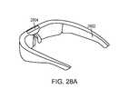
- the methodincludes manipulating one or more virtual objects displayed on a device based on the identified position and shape of the object.
- the devicemay be a head-mounted device or a TV.
- the identified position and shape of the objectis used to manipulate the virtual object via wireless cell phone communication.
- the methodfurther includes authenticating a user based on the detected shape of the object and/or the detected motion of the object and subsequent matching thereof to data in a database record corresponding to the user.
- the inventionin another aspect, relates to a system for identifying a position and shape of an object in 3D space.
- the systemincludes one or more cameras (e.g., a time-of-flight camera) oriented toward a field of view; one or more sources (e.g., a light source or a sonic source) to direct illumination onto the object in the field of view; and an image analyzer coupled to the camera and the source and configured to operate the camera to capture one or more images of the object and identify a position and shape of the object in 3D space based on the captured image and a location of the source.
- camerase.g., a time-of-flight camera
- sourcese.g., a light source or a sonic source
- the one or more light sourcesinclude multiple light sources each aligned in a line or in a plane. Additionally, the system may include multiple filters placed on light sensors of the camera to generate multiple images, each of which corresponds to a color filter.
- the image analyzeris further configured to (i) slice the object into multiple 2D slices each corresponding to a cross-section of the object, (ii) identify a shape and position of the object based at least in part on an image captured by the camera and a location of the one or more light source, and (iii) reconstruct the position and shape of the object in 3D space based at least in part on the multiple identified cross-sectional shapes and positions of the object.
- the image analyzeris further configured to define a 3D model of the object and reconstruct the position and shape of the object in 3D space based on the 3D model.
- the systemfurther includes a secondary device (e.g., a head-mounted device or a mobile device) operatively connected to the system.
- the secondary devicemay be an authentication server for authenticating a user based on a shape and/or a jitter of the user's hand detected by the image analyzer.
- FIG. 1is a simplified illustration of a motion capture system according to an embodiment of the present invention
- FIG. 2is a simplified block diagram of a computer system that can be used according to an embodiment of the present invention
- FIGS. 3A (top view) and 3 B (side view)are conceptual illustrations of how slices are defined in a field of view according to an embodiment of the present invention
- FIGS. 4A-4Care top views illustrating an analysis that can be performed on a given slice according to an embodiment of the present invention.
- FIG. 4Ais a top view of a slice.
- FIG. 4Billustrates projecting edge points from an image plane to a vantage point to define tangent lines.
- FIG. 4Cillustrates fitting an ellipse to tangent lines as defined in FIG. 4B ;
- FIG. 5graphically illustrates an ellipse in the xy plane characterized by five parameters
- FIGS. 6A and 6Bprovide a flow diagram of a motion-capture process according to an embodiment of the present invention
- FIG. 7graphically illustrates a family of ellipses that can be constructed from four tangent lines
- FIG. 8sets forth a general equation for an ellipse in the xy plane
- FIG. 9graphically illustrates how a centerline can be found for an intersection region with four tangent lines according to an embodiment of the present invention.
- FIGS. 10A-10Nset forth equations that can be solved to fit an ellipse to four tangent 15 lines according to an embodiment of the present invention
- FIGS. 11A-11Care top views illustrating instances of slices containing multiple disjoint cross-sections according to various embodiments of the present invention.
- FIG. 12graphically illustrates a model of a hand that can be generated using a motion capture system according to an embodiment of the present invention
- FIG. 13is a simplified system diagram for a motion-capture system with three cameras according to an embodiment of the present invention.
- FIG. 14illustrates a cross-section of an object as seen from three vantage points in the system of FIG. 13 ;
- FIG. 15graphically illustrates a technique that can be used to find an ellipse from at least five tangents according to an embodiment of the present invention
- FIG. 16schematically illustrates a system for capturing shadows of an object according to an embodiment of the present invention
- FIG. 17schematically illustrates an ambiguity that can occur in the system of FIG. 16 ;
- FIG. 18schematically illustrates another system for capturing shadows of an object according to another embodiment of the present invention.
- FIG. 19graphically depicts a collection of the intersection regions defined by a virtual rubber band stretched around multiple intersection regions in accordance with an embodiment of the invention
- FIG. 20schematically illustrates a simple intersection region constructed using two light sources in accordance with an embodiment of the invention
- FIGS. 21A , 21 B and 21 Cschematically depict determinations of true intersection points in accordance with various embodiments of the invention.
- FIG. 22schematically depicts an intersection region uniquely identified using a group of the intersection points
- FIG. 23illustrates an image coordinate system incorporated to define the locations of the shadows in accordance with an embodiment of the invention
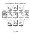
- FIG. 24Aillustrates separate color images captured using color filters in accordance with an embodiment of the invention
- FIG. 24Bdepicts a reconstructed 3D image of the object
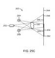
- FIGS. 25A , 25 B and 25 Cschematically illustrate a system for capturing an image of both the object and one or more shadows cast by the object from one or more light sources at known positions according to an embodiment of the present invention
- FIG. 26schematically illustrates a camera-and-beamsplitter setup for a motion capture system according to another embodiment of the present invention.
- FIG. 27schematically illustrates a camera-and-pinhole setup for a motion capture system according to another embodiment of the present invention.
- FIGS. 28A , 28 B, and 28 Cdepict a motion capture system operatively connected to a head-mounted device, a mobile device, and an authentication server, respectively.
- Embodiments of the present inventionrelate to methods and systems for capturing motion and/or determining position of an object using small amounts of information.
- an outline of an object's shape, or silhouette, as seen from a particular vantage pointcan be used to define tangent lines to the object from that vantage point in various planes, referred to herein as “slices.”
- tangent lines to the object from that vantage point in various planesreferred to herein as “slices.”
- four (or more) tangent lines from the vantage points to the objectcan be obtained in a given slice. From these four (or more) tangent lines, it is possible to determine the position of the object in the slice and to approximate its cross-section in the slice, e.g., using one or more ellipses or other simple closed curves.
- locations of points on an object's surface in a particular slicecan be determined directly (e.g., using a time-of-flight camera), and the position and shape of a cross-section of the object in the slice can be approximated by fitting an ellipse or other simple closed curve to the points.
- Positions and cross-sections determined for different slicescan be correlated to construct a 3D model of the object, including its position and shape.
- a succession of imagescan be analyzed using the same technique to model motion of the object.
- Motion of a complex object that has multiple separately articulating memberse.g., a human hand
- the silhouettes of an objectare extracted from one or more images of the object that reveal information about the object as seen from different vantage points. While silhouettes can be obtained using a number of different techniques, in some embodiments, the silhouettes are obtained by using cameras to capture images of the object and analyzing the images to detect object edges.
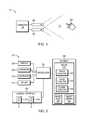
- FIG. 1is a simplified illustration of a motion capture system 100 according to an embodiment of the present invention.
- System 100includes two cameras 102 , 104 arranged such that their fields of view (indicated by broken lines) overlap in region 110 .
- Cameras 102 and 104are coupled to provide image data to a computer 106 .
- Computer 106analyzes the image data to determine the 3D position and motion of an object, e.g., a hand 108 , that moves in the field of view of cameras 102 , 104 .
- Cameras 102 , 104can be any type of camera, including visible-light cameras, infrared (IR) cameras, ultraviolet cameras or any other devices (or combination of devices) that are capable of capturing an image of an object and representing that image in the form of digital data. Cameras 102 , 104 are preferably capable of capturing video images (i.e., successive image frames at a constant rate of at least 15 frames per second), although no particular frame rate is required.
- the particular capabilities of cameras 102 , 104are not critical to the invention, and the cameras can vary as to frame rate, image resolution (e.g., pixels per image), color or intensity resolution (e.g., number of bits of intensity data per pixel), focal length of lenses, depth of field, etc.
- any cameras capable of focusing on objects within a spatial volume of interestcan be used.
- the volume of interestmight be a meter on a side.
- the volume of interestmight be tens of meters in order to observe several strides (or the person might run on a treadmill, in which case the volume of interest can be considerably smaller).
- the camerascan be oriented in any convenient manner.
- respective optical axes 112 , 114 of cameras 102 and 104are parallel, but this is not required.
- each camerais used to define a “vantage point” from which the object is seen, and it is required only that a location and view direction associated with each vantage point be known, so that the locus of points in space that project onto a particular position in the camera's image plane can be determined.
- motion captureis reliable only for objects in area 110 (where the fields of view of cameras 102 , 104 overlap), and cameras 102 , 104 may be arranged to provide overlapping fields of view throughout the area where motion of interest is expected to occur.
- FIG. 2is a simplified block diagram of computer system 200 implementing computer 106 according to an embodiment of the present invention.
- Computer system 200includes a processor 202 , a memory 204 , a camera interface 206 , a display 208 , speakers 209 , a keyboard 210 , and a mouse 211 .
- Processor 202can be of generally conventional design and can include, e.g., one or more programmable microprocessors capable of executing sequences of instructions.
- Memory 204can include volatile (e.g., DRAM) and nonvolatile (e.g., flash memory) storage in any combination. Other storage media (e.g., magnetic disk, optical disk) can also be provided.
- Memory 204can be used to store instructions to be executed by processor 202 as well as input and/or output data associated with execution of the instructions.
- Camera interface 206can include hardware and/or software that enables communication between computer system 200 and cameras such as cameras 102 , 104 of FIG. 1 .
- camera interface 206can include one or more data ports 216 , 218 to which cameras can be connected, as well as hardware and/or software signal processors to modify data signals received from the cameras (e.g., to reduce noise or reformat data) prior to providing the signals as inputs to a conventional motion-capture (“mocap”) program 214 executing on processor 202 .
- camera interface 206can also transmit signals to the cameras, e.g., to activate or deactivate the cameras, to control camera settings (frame rate, image quality, sensitivity, etc.), or the like. Such signals can be transmitted, e.g., in response to control signals from processor 202 , which may in turn be generated in response to user input or other detected events.
- memory 204can store mocap program 214 , which includes instructions for performing motion capture analysis on images supplied from cameras connected to camera interface 206 .
- mocap program 214includes various modules, such as an image analysis module 222 , a slice analysis module 224 , and a global analysis module 226 .
- Image analysis module 222can analyze images, e.g., images captured via camera interface 206 , to detect edges or other features of an object.
- Slice analysis module 224can analyze image data from a slice of an image as described below, to generate an approximate cross-section of the object in a particular plane.
- Global analysis module 226can correlate cross-sections across different slices and refine the analysis. Examples of operations that can be implemented in code modules of mocap program 214 are described below.
- Memory 204can also include other information used by mocap program 214 ; for example, memory 204 can store image data 228 and an object library 230 that can include canonical models of various objects of interest. As described below, an object being modeled can be identified by matching its shape to a model in object library 230 .
- Display 208 , speakers 209 , keyboard 210 , and mouse 211can be used to facilitate user interaction with computer system 200 . These components can be of generally conventional design or modified as desired to provide any type of user interaction.
- results of motion capture using camera interface 206 and mocap program 214can be interpreted as user input. For example, a user can perform hand gestures that are analyzed using mocap program 214 , and the results of this analysis can be interpreted as an instruction to some other program executing on processor 200 (e.g., a web browser, word processor or the like).
- a usermight be able to use upward or downward swiping gestures to “scroll” a webpage currently displayed on display 208 , to use rotating gestures to increase or decrease the volume of audio output from speakers 209 , and so on.
- Computer system 200is illustrative and that variations and modifications are possible.
- Computerscan be implemented in a variety of form factors, including server systems, desktop systems, laptop systems, tablets, smart phones or personal digital assistants, and so on.
- a particular implementationmay include other functionality not described herein, e.g., wired and/or wireless network interfaces, media playing and/or recording capability, etc.
- one or more camerasmay be built into the computer rather than being supplied as separate components.
- cameras 102 , 104are operated to collect a sequence of images of an object 108 .
- the imagesare time correlated such that an image from camera 102 can be paired with an image from camera 104 that was captured at the same time (within a few milliseconds).
- These imagesare then analyzed, e.g., using mocap program 214 , to determine the object's position and shape in 3D space.
- the analysisconsiders a stack of 2D cross-sections through the 3D spatial field of view of the cameras. These cross-sections are referred to herein as “slices.”
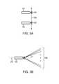
- FIGS. 3A and 3Bare conceptual illustrations of how slices are defined in a field of view according to an embodiment of the present invention.
- FIG. 3Ashows, in top view, cameras 102 and 104 of FIG. 1 .
- Camera 102defines a vantage point 302
- camera 104defines a vantage point 304 .
- Line 306joins vantage points 302 and 304 .
- FIG. 3Bshows a side view of cameras 102 and 104 ; in this view, camera 104 happens to be directly behind camera 102 and thus occluded; line 306 is perpendicular to the plane of the drawing.
- top and sideare arbitrary; regardless of how the cameras are actually oriented in a particular setup, the “top” view can be understood as a view looking along a direction normal to the plane of the cameras, while the “side” view is a view in the plane of the cameras.)
- a “slice”can be any one of those planes for which at least part of the plane is in the field of view of cameras 102 and 104 .
- Several slices 308are shown in FIG. 3B . (Slices 308 are seen edge-on; it is to be understood that they are 2D planes and not 1-D lines.)
- slicescan be selected at regular intervals in the field of view. For example, if the received images include a fixed number of rows of pixels (e.g., 1080 rows), each row can be a slice, or a subset of the rows can be used for faster processing. Where a subset of the rows is used, image data from adjacent rows can be averaged together, e.g., in groups of 2-3.
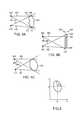
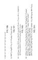
- FIGS. 4A-4Cillustrate an analysis that can be performed on a given slice.
- FIG. 4Ais a top view of a slice as defined above, corresponding to an arbitrary cross-section 402 of an object. Regardless of the particular shape of cross-section 402 , the object as seen from a first vantage point 404 has a “left edge” point 406 and a “right edge” point 408 . As seen from a second vantage point 410 , the same object has a “left edge” point 412 and a “right edge” point 414 . These are in general different points on the boundary of object 402 . A tangent line can be defined that connects each edge point and the associated vantage point. For example, FIG.
- tangent line 416can be defined through vantage point 404 and left edge point 406 ; tangent line 418 through vantage point 404 and right edge point 408 ; tangent line 420 through vantage point 410 and left edge point 412 ; and tangent line 422 through vantage point 410 and right edge point 414 .
- FIG. 4Bis another top view of a slice, showing the image plane for each vantage point.
- Image 440is obtained from vantage point 442 and shows left edge point 446 and right edge point 448 .
- Image 450is obtained from vantage point 452 and shows left edge point 456 and right edge point 458 .
- Tangent lines 462 , 464 , 466 , 468can be defined as shown.
- the location in the slice of an elliptical cross-sectioncan be determined, as illustrated in FIG. 4C , where ellipse 470 has been fit to tangent lines 462 , 464 , 466 , 468 of FIG. 4B .
- an ellipse in the xy planecan be characterized by five parameters: the x and y coordinates of the center (x C , y C ), the semimajor axis (a), the semiminor axis (b), and a rotation angle ( ⁇ ) (e.g., the angle of the semimajor axis relative to the x axis).
- ⁇rotation angle
- This additional informationcan include, for example, physical constraints based on properties of the cameras and/or the object.
- more than four tangents to an objectmay be available for some or all of the slices, e.g., because more than two vantage points are available.
- An elliptical cross-sectioncan still be determined, and the process in some instances is somewhat simplified as there is no need to assume a parameter value.
- the additional tangentsmay create additional complexity. Examples of processes for analysis using more than four tangents are described below and in the '554 application noted above.
- fewer than four tangents to an objectmay be available for some or all of the slices, e.g., because an edge of the object is out of range of the field of view of one camera or because an edge was not detected.
- a slice with three tangentscan be analyzed. For example, using two parameters from an ellipse fit to an adjacent slice (e.g., a slice that had at least four tangents), the system of equations for the ellipse and three tangents is sufficiently determined that it can be solved.
- a circlecan be fit to the three tangents; defining a circle in a plane requires only three parameters (the center coordinates and the radius), so three tangents suffice to fit a circle.
- Slices with fewer than three tangentscan be discarded or combined with adjacent slices.
- each of a number of slicesis analyzed separately to determine the size and location of an elliptical cross-section of the object in that slice.
- Thisprovides an initial 3D model (specifically, a stack of elliptical cross-sections), which can be refined by correlating the cross-sections across different slices. For example, it is expected that an object's surface will have continuity, and discontinuous ellipses can accordingly be discounted. Further refinement can be obtained by correlating the 3D model with itself across time, e.g., based on expectations related to continuity in motion and deformation.
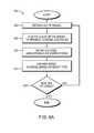
- FIGS. 6A-6Bprovide a flow diagram of a motion-capture process 600 according to an embodiment of the present invention.
- Process 600can be implemented, e.g., in mocap program 214 of FIG. 2 .
- a set of imagese.g., one image from each camera 102 , 104 of FIG. 1 —is obtained.
- the images in a setare all taken at the same time (or within a few milliseconds), although a precise timing is not required.
- the techniques described herein for constructing an object modelassume that the object is in the same place in all images in a set, which will be the case if images are taken at the same time. To the extent that the images in a set are taken at different times, motion of the object may degrade the quality of the result, but useful results can be obtained as long as the time between images in a set is small enough that the object does not move far, with the exact limits depending on the particular degree of precision desired.
- each sliceis analyzed.
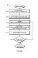
- FIG. 6Billustrates a per-slice analysis that can be performed at block 604 .
- edge points of the object in a given sliceare identified in each image in the set. For example, edges of an object in an image can be detected using conventional techniques, such as contrast between adjacent pixels or groups of pixels. In some embodiments, if no edge points are detected for a particular slice (or if only one edge point is detected), no further analysis is performed on that slice. In some embodiments, edge detection can be performed for the image as a whole rather than on a per-slice basis.
- an initial assumption as to the value of one of the parameters of an ellipseis made, to reduce the number of free parameters from five to four.
- the initial assumptioncan be, e.g., the semimajor axis (or width) of the ellipse.
- an assumptioncan be made as to eccentricity (ratio of semimajor axis to semiminor axis), and that assumption also reduces the number of free parameters from five to four.
- the assumed valuecan be based on prior information about the object.
- a parameter valuecan be assumed based on typical dimensions for objects of that type (e.g., an average cross-sectional dimension of a palm or finger).
- An arbitrary assumptioncan also be used, and any assumption can be refined through iterative analysis as described below.
- the tangent lines and the assumed parameter valueare used to compute the other four parameters of an ellipse in the plane.
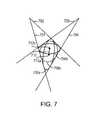
- four tangent lines 701 , 702 , 703 , 704define a family of inscribed ellipses 706 including ellipses 706 a , 706 b , and 706 c , where each inscribed ellipse 706 is tangent to all four of lines 701 - 704 .
- Ellipse 706 a and 706 brepresent the “extreme” cases (i.e., the most eccentric ellipses that are tangent to all four of lines 701 - 704 . Intermediate between these extremes are an infinite number of other possible ellipses, of which one example, ellipse 706 c , is shown (dashed line).
- the solution processselects one (or in some instances more than one) of the possible inscribed ellipses 706 . In one embodiment, this can be done with reference to the general equation for an ellipse shown in FIG. 8 .
- the notationfollows that shown in FIG. 5 , with (x, y) being the coordinates of a point on the ellipse, (x C , y C ) the center, a and b the axes, and ⁇ the rotation angle.
- the coefficients C 1 , C 2 and C 3are defined in terms of these parameters, as shown in FIG. 8 .
- the number of free parameterscan be reduced based on the observation that the centers (x C , y C ) of all the ellipses in family 706 line on a line segment 710 (also referred to herein as the “centerline”) between the center of ellipse 706 a (shown as point 712 a ) and the center of ellipse 706 b (shown as point 712 b ).
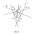
- FIG. 9illustrates how a centerline can be found for an intersection region.
- Region 902is a “closed” intersection region; that is, it is bounded by tangents 904 , 906 , 908 , 910 .
- the centerlinecan be found by identifying diagonal line segments 912 , 914 that connect the opposite corners of region 902 , identifying the midpoints 916 , 918 of these line segments, and identifying the line segment 920 joining the midpoints as the centerline.
- Region 930is an “open” intersection region; that is, it is only partially bounded by tangents 904 , 906 , 908 , 910 . In this case, only one diagonal, line segment 932 , can be defined.
- centerline 920 from closed intersection region 902can be extended into region 930 as shown. The portion of extended centerline 920 that is beyond line segment 932 is centerline 940 for region 930 .
- both region 902 and region 930can be considered during the solution process.
- the ellipse equation of FIG. 8is solved for ⁇ , subject to the constraints that: (1) (x C , y C ) must lie on the centerline determined from the four tangents (i.e., either centerline 920 or centerline 940 of FIG. 9 ); and (2) a is fixed at the assumed value a 0 .
- the ellipse equationcan either be solved for ⁇ analytically or solved using an iterative numerical solver (e.g., a Newtonian solver as is known in the art).
- FIGS. 10A-10DOne analytic solution is illustrated in the equations of FIGS. 10A-10D .
- FIG. 10Billustrates the definition of four column vectors r 12 , r 23 , r 14 and r 24 from the coefficients of FIG. 10A .
- FIG. 10Cillustrates the definition of G and H, which are four-component vectors from the vectors of tangent coefficients A, B and D and scalar quantities p and q, which are defined using the column vectors r 12 , r 23 , r 14 and r 24 from FIG. 10B .
- FIG. Dillustrates the definition of six scalar quantities v A2 , v AB , v B2 , w A2 , w AB , and w B2 in terms of the components of vectors G and H of FIG. 10C .
- the parameters A 1 , B 1 , G 1 , H 1 , v A2 , v AB , v B2 , w A2 , w AB , and w B2 used in FIGS. 10E-10Nare defined as shown in FIGS. 10A-10D .
- the solutionsare filtered by applying various constraints based on known (or inferred) physical properties of the system. For example, some solutions would place the object outside the field of view of the cameras, and such solutions can readily be rejected.
- the type of object being modeledis known (e.g., it can be known that the object is or is expected to be a human hand). Techniques for determining object type are described below; for now, it is noted that where the object type is known, properties of that object can be used to rule out solutions where the geometry is inconsistent with objects of that type.
- human handshave a certain range of sizes and expected eccentricities in various cross-sections, and such ranges can be used to filter the solutions in a particular slice.
- constraintscan be represented in any suitable format, e.g., a physical model (as described below), an ordered list of parameters based on such a model, etc.
- cross-slice correlationscan also be used to filter (or further filter) the solutions obtained at block 612 .
- constraints on the spatial relationship between various parts of the hande.g., fingers have a limited range of motion relative to each other and/or to the palm of the hand
- constraints on the spatial relationship between various parts of the hande.g., fingers have a limited range of motion relative to each other and/or to the palm of the hand
- constraints on the spatial relationship between various parts of the hande.g., fingers have a limited range of motion relative to each other and/or to the palm of the hand
- constraints on the spatial relationship between various parts of the hande.g., fingers have a limited range of motion relative to each other and/or to the palm of the hand
- constraints on the spatial relationship between various parts of the hande.g., fingers have a limited range of motion relative to each other and/or to the palm of the hand
- constraints on the spatial relationship between various parts of the hande.g., fingers have a limited range of motion
- process 600it is determined whether a satisfactory solution has been found. Various criteria can be used to assess whether a solution is satisfactory. For instance, if a unique solution is found (after filtering), that solution can be accepted, in which case process 600 proceeds to block 620 (described below). If multiple solutions remain or if all solutions were rejected in the filtering at block 614 , it may be desirable to retry the analysis. If so, process 600 can return to block 610 , allowing a change in the assumption used in computing the parameters of the ellipse.
- Retryingcan be triggered under various conditions.
- the analysiscan be retried with a different assumption.
- a small constant(which can be positive or negative) is added to the initial assumed parameter value (e.g., a 0 ) and the new value is used to generate a new set of solutions. This can be repeated until an acceptable solution is found (or until the parameter value reaches a limit).
- multiple elliptical cross-sectionsmay be found in some or all of the slices.
- a complex objecte.g., a hand
- may have a cross-section with multiple disjoint elementse.g., in a plane that intersects the fingers.
- Ellipse-based reconstruction techniques as described hereincan account for such complexity; examples are described below. Thus, it is generally not required that a single ellipse be found in a slice, and in some instances, solutions entailing multiple ellipses may be favored.
- FIG. 6BFor a given slice, the analysis of FIG. 6B yields zero or more elliptical cross-sections. In some instances, even after filtering at block 616 , there may still be two or more possible solutions. These ambiguities can be addressed in further processing as described below.
- the per-slice analysis of block 604can be performed for any number of slices, and different slices can be analyzed in parallel or sequentially, depending on available processing resources.
- the resultis a 3D model of the object, where the model is constructed by, in effect, stacking the slices.
- cross-slice correlationsare used to refine the model. For example, as noted above, in some instances, multiple solutions may have been found for a particular slice.
- block 620can be performed iteratively as each slice is analyzed.
- the 3D modelcan be further refined, e.g., based on an identification of the type of object being modeled.
- a library of object typescan be provided (e.g., as object library 230 of FIG. 2 ).
- the librarycan provide characteristic parameters for the object in a range of possible poses (e.g., in the case of a hand, the poses can include different finger positions, different orientations relative to the cameras, etc.).
- a reconstructed 3D modelcan be compared to various object types in the library. If a match is found, the matching object type is assigned to the model.
- block 622can include recomputing all or portions of the per-slice analysis (block 604 ) and/or cross-slice correlation analysis (block 620 ) subject to the type-based constraints.
- applying type-based constraintsmay cause deterioration in accuracy of reconstruction if the object is misidentified. (Whether this is a concern depends on implementation, and type-based constraints can be omitted if desired.)
- object library 230can be dynamically and/or iteratively updated. For example, based on characteristic parameters, an object being modeled can be identified as a hand. As the motion of the hand is modeled across time, information from the model can be used to revise the characteristic parameters and/or define additional characteristic parameters, e.g., additional poses that a hand may present.
- refinement at block 622can also include correlating results of analyzing images across time. It is contemplated that a series of images can be obtained as the object moves and/or articulates. Since the images are expected to include the same object, information about the object determined from one set of images at one time can be used to constrain the model of the object at a later time. (Temporal refinement can also be performed “backward” in time, with information from later images being used to refine analysis of images at earlier times.)
- a next set of imagescan be obtained, and process 600 can return to block 604 to analyze slices of the next set of images.
- analysis of the next set of imagescan be informed by results of analyzing previous sets. For example, if an object type was determined, type-based constraints can be applied in the initial per-slice analysis, on the assumption that successive images are of the same object.
- imagescan be correlated across time, and these correlations can be used to further refine the model, e.g., by rejecting discontinuous jumps in the object's position or ellipses that appear at one time point but completely disappear at the next.
- motion capture process described hereinis illustrative and that variations and modifications are possible. Steps described as sequential may be executed in parallel, order of steps may be varied, and steps may be modified, combined, added or omitted. Different mathematical formulations and/or solution procedures can be substituted for those shown herein. Various phases of the analysis can be iterated, as noted above, and the degree to which iterative improvement is used may be chosen based on a particular application of the technology. For example, if motion capture is being used to provide real-time interaction (e.g., to control a computer system), the data capture and analysis should be performed fast enough that the system response feels like real time to the user.
- an analysis with more iterations that produces a more refined (and accurate) modelmay be preferred.
- an object being modeledcan be a “complex” object and consequently may present multiple discrete ellipses in some cross-sections.
- a handhas fingers, and a cross-section through the fingers may include as many as five discrete elements.
- the analysis techniques described abovecan be used to model complex objects.
- FIGS. 11A-11Cillustrate some cases of interest.
- cross-sections 1102 , 1104would appear as distinct objects in images from both of vantage points 1106 , 1108 .
- objectit is possible to distinguish object from background; for example, in an infrared image, a heat-producing object (e.g., living organisms) may appear bright against a dark background.
- tangent lines 1110 and 1111can be identified as a pair of tangents associated with opposite edges of one apparent object while tangent lines 1112 and 1113 can be identified as a pair of tangents associated with opposite edges of another apparent object.
- tangent lines 1114 and 1115 , and tangent lines 1116 and 1117can be paired. If it is known that vantage points 1106 and 1108 are on the same side of the object to be modeled, it is possible to infer that tangent pairs 1110 , 1111 and 1116 , 1117 should be associated with the same apparent object, and similarly for tangent pairs 1112 , 1113 and 1114 , 1115 . This reduces the problem to two instances of the ellipse-fitting process described above. If less information is available, an optimum solution can be determined by iteratively trying different possible assignments of the tangents in the slice in question, rejecting non-physical solutions, and cross-correlating results from other slices to determine the most likely set of ellipses.
- ellipse 1120partially occludes ellipse 1122 from both vantage points.
- ellipse 1140fully occludes ellipse 1142 .
- the analysis described abovewould not show ellipse 1142 in this particular slice.
- spatial correlations across slices, temporal correlations across image sets, and/or physical constraints based on object typecan be used to infer the presence of ellipse 1142 , and its position can be further constrained by the fact that it is apparently occluded.
- multiple discrete cross-sectionse.g., in any of FIGS. 11A-11C
- a motion capture systemcan be used to detect the 3D position and movement of a human hand.
- two camerasare arranged as shown in FIG. 1 , with a spacing of about 1.5 cm between them.
- Each camerais an infrared camera with an image rate of about 60 frames per second and a resolution of 640 ⁇ 480 pixels per frame.
- An infrared light sourcee.g., an IR light-emitting diode
- An infrared light sourcethat approximates a point light source is placed between the cameras to create a strong contrast between the object of interest (in this case, a hand) and background. The falloff of light with distance creates a strong contrast if the object is a few inches away from the light source while the background is several feet away.
- the imageis analyzed using contrast between adjacent pixels to detect edges of the object.
- Bright pixels(detected illumination above a threshold) are assumed to be part of the object while dark pixels (detected illumination below a threshold) are assumed to be part of the background.
- Edge detectionmay take approximately 2 ms with conventional processing capability.
- the edges and the known camera positionsare used to define tangent lines in each of 480 slices (one slice per row of pixels), and ellipses are determined from the tangents using the analytical technique described above with reference to FIGS. 6A and 6B .
- roughly 800-1200 ellipsesare generated from a single pair of image frames (the number depends on the orientation and shape of the hand) within, in various embodiments, about 6 ms.
- the error in modeling finger positionin one embodiment is less than 0.1 mm.
- FIG. 12illustrates a model 1200 of a hand that can be generated using the system just described.
- the modeldoes not have the exact shape of a hand, but a palm 1202 , thumb 1204 and four fingers 1206 can be clearly recognized.
- Such modelscan be useful as the basis for constructing more realistic models.
- a skeleton model for a handcan be defined, and the positions of various joints in the skeleton model can be determined by reference to model 1200 .
- a more realistic image of a handcan be rendered.
- a more realistic modelmay not be needed.
- model 1200accurately indicates the position of thumb 1204 and fingers 1206 , and a sequence of models 1200 captured across time will indicate movement of these digits.
- gesturescan be recognized directly from model 1200 .
- the pointis that ellipses identified and tracked as described above can be used to drive visual representations of the object tracked by application to a physical model of the object.
- the modelmay be selected based on a desired degree of realism, the response time desired (or the latency that can be tolerated), and available computational resources.
- this example systemis illustrative and that variations and modifications are possible.
- Different types and arrangements of camerascan be used, and appropriate image analysis techniques can be used to distinguish object from background and thereby determine a silhouette (or a set of edge locations for the object) that can in turn be used to define tangent lines to the object in various 2D slices as described above.
- a variety of imaging systems and techniquescan be used to capture images of an object that can be used for edge detection. In some cases, more than four tangents can be determined in a given slice. For example, more than two vantage points can be provided.
- FIG. 13is a simplified system diagram for a system 1300 with three cameras 1302 , 1304 , 1306 according to an embodiment of the present invention.
- Each camera 1302 , 1304 , 1306provides a vantage point 1308 , 1310 , 1312 and is oriented toward an object of interest 1313 .
- cameras 1302 , 1304 , 1306are arranged such that vantage points 1308 , 1310 , 1312 lie in a single line 1314 in 3D space.
- Two-dimensional slicescan be defined as described above, except that all three vantage points 1308 , 1310 , 1312 are included in each slice.
- FIG. 14illustrates a cross-section 1402 of an object as seen from vantage points 1308 , 1310 , 1312 .
- Lines 1408 , 1410 , 1412 , 1414 , 1416 , 1418are tangent lines to cross-section 1402 from vantage points 1308 , 1310 , 1312 , respectively.
- FIG. 15illustrates one technique, relying on the “centerline” concept illustrated above in FIG. 9 . From a first set of four tangents 1502 , 1504 , 1506 , 1508 associated with a first pair of vantage points, a first intersection region 1510 and corresponding centerline 1512 can be determined. From a second set of four tangents 1504 , 1506 , 1514 , 1516 associated with a second pair of vantage points, a second intersection region 1518 and corresponding centerline 1520 can be determined.
- the ellipse of interest 1522should be inscribed in both intersection regions.
- the center of ellipse 1522is therefore the intersection point 1524 of centerlines 1512 and 1520 .
- one of the vantage points (and the corresponding two tangents 1504 , 1506 )are used for both sets of tangents. Given more than three vantage points, the two sets of tangents could be disjoint if desired.
- the elliptical cross-sectionis mathematically overdetermined.
- the extra informationcan be used to refine the elliptical parameters, e.g., using statistical criteria for a best fit.
- the extra informationcan be used to determine an ellipse for every combination of five tangents, then combine the elliptical contours in a piecewise fashion.
- the extra informationcan be used to weaken the assumption that the cross-section is an ellipse and allow for a more detailed contour. For example, a cubic closed curve can be fit to five or more tangents.
- data from three or more vantage pointsis used where available, and four-tangent techniques (e.g., as described above) can be used for areas that are within the field of view of only two of the vantage points, thereby expanding the spatial range of a motion-capture system.
- the objectis projected onto an image plane using two different cameras to provide the two different vantage points, and the edge points are defined in the image plane of each camera.
- the edge pointsare defined in the image plane of each camera.
- a light sourcecan create a shadow of an object on a target surface, and the shadow—captured as an image of the target surface—can provide a projection of the object that suffices for detecting edges and defining tangent lines.
- the light sourcecan produce light in any visible or non-visible portion of the electromagnetic spectrum. Any frequency (or range of frequencies) can be used, provided that the object of interest is opaque to such frequencies while the ambient environment in which the object moves is not.
- the light sources usedshould be bright enough to cast distinct shadows on the target surface. Point-like light sources provide sharper edges than diffuse light sources, but any type of light source can be used.
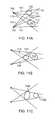
- FIG. 16illustrates a system 1600 for capturing shadows of an object according to an embodiment of the present invention.
- Light sources 1602 and 1604illuminate an object 1606 , casting shadows 1608 , 1610 onto a front side 1612 of a surface 1614 .
- Surface 1614can be translucent so that the shadows are also visible on its back side 1616 .
- a camera 1618can be oriented toward back side 1616 as shown and can capture images of shadows 1608 , 1610 . With this arrangement, object 1606 does not occlude the shadows captured by camera 1618 .
- Light sources 1602 and 1604define two vantage points, from which tangent lines 1620 , 1622 , 1624 , 1626 can be determined based on the edges of shadows 1608 , 1610 . These four tangents can be analyzed using techniques described above.
- Shadows created by different light sourcesmay partially overlap, depending on where the object is placed relative to the light source.
- an imagemay have shadows with penumbra regions (where only one light source is contributing to the shadow) and an umbra region (where the shadows from both light sources overlap).
- Detecting edgescan include detecting the transition from penumbra to umbra region (or vice versa) and inferring a shadow edge at that location. Since an umbra region will be darker than a penumbra region; contrast-based analysis can be used to detect these transitions.
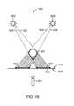
- Certain physical or object configurationsmay present ambiguities that are resolved in accordance with various embodiments we as now discussed.
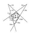
- the camera 1720may detect four shadows 1712 , 1714 , 1716 , 1718 and the tangent lines may create four intersection regions 1722 , 1724 , 1726 , 1728 that all lie within the shadow regions 1730 , 1732 , 1734 , 1736 . Because it is difficult to determine, from a single slice of the shadow image, which of these intersection regions contain portions of the object, an analysis of whether the intersection regions 1722 , 1724 , 1726 , 1728 are occupied by the objects may be ambiguous.
- shadows 1712 , 1714 , 1716 , 1718 that are generated when intersection regions 1722 and 1726 are occupiedare the same as those generated when regions 1724 and 1728 are occupied, or when all four intersection regions 1722 , 1724 , 1726 , 1728 are occupied.
- correlations across slicesare used to resolve the ambiguity in interpreting the intersection regions (or “visual hulls”) 1722 , 1724 , 1726 , 1728 .
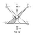
- a system 1800incorporates a large number of light sources (i.e., more than two light sources) to resolve the ambiguity of the intersection regions when there are multiple objects casting shadows.
- the system 1800includes three light sources 1802 , 1804 , 1806 to cast light onto a translucent surface 1810 and a camera 1812 positioned on the opposite side of surface 1810 to avoid occluding the shadows cast by an object 1814 .
- the ellipse-fitting techniques described abovemay be used to determine the cross-sections of the objects.
- a collection of the cross-sections of the objects in 2D slicesmay then determine the locations and/or movement of the objects.
- intersection regionsmay be too small to be analyzed based on a known or assumed size scale of the object. Additionally, the increased number of intersection regions may result in more ambiguity in distinguishing intersection regions that contain objects from intersection regions that do not contain objects (i.e., “blind spots”). In various embodiments, whether an intersection region contains an object is determined based on the properties of a collection of intersection points therein.
- an intersection pointis defined by at least two shadow lines, each connecting a shadow point of the shadow and a light source. If the intersection points in an intersection region satisfy certain criteria, the intersection region is considered to have the objects therein. A collection of the intersection regions may then be utilized to determine the shape and movement of the objects.
- a collection of the intersection regions (a visual hull) 1930is defined by a virtual rubber band 1932 stretched around multiple intersection regions 1931 (or “convex hulls”); each intersection region 1931 is defined by a smallest set of intersection points 1934 .
- the light source L 1 and shadow 2006 Adefine a shadow region, R 1,1 ; similarly, light source L 2 and the shadow 2006 B define a shadow region, R 2,1 ; in general, the shadow region is denoted as, R u,v , where u is the number of the corresponding light source and v is a number that denotes a left to right ordering in a scene within the set of all shadow regions from the light source u. Boundaries of the shadows (or “shadow points”) lie on an x axis and are denoted by S u,v .
- the shadow points and each light sourcemay then create shadow lines 2008 , 2010 , 2012 , 2014 ; the shadow lines are referenced by the two connecting points; for example, L 1 S 1,2 , (abbreviated S 1,2 , where the first subscript also refers to the light number).
- the convex hull 2030(or visual hull here since there is only one intersection region 2028 ) may then be defined by the four intersection points 2034 in the example of FIG. 20 .
- the intersection points 2034are determined based on the intersections of every pair of shadow lines, for example, S 1,1 , S 1,2 , S 2,1 , and S 2,2 . Because pairs of shadow lines from the same light source L 1 or L 2 do not intersect, the intersection of the pairs of lines from the same light source may then be neglected.
- intersection points 2134 A, 2134 B, 2134 C, 2134 D, 2134 E, 2134 Fmay result in “true” intersection points 2134 A, 2134 B, 2134 C, 2134 D, 2134 E, 2134 F that form the intersection region 2128 occupied by the object 2108 and “false” intersection points 2135 A, 2135 B, 2135 C, 2135 D, 2135 E, 2135 F that clearly do not form the intersection region 2128 .
- the false intersection point 2135 E created by a left shadow line 2124 of the shadow region 2118 A and a right shadow line 2126 of the shadow region 2118 Bis a false intersection point because it does not lie inside the intersection region 2128 .
- the intersection region 2128is an intersection of the shadow regions 2118 A, 2118 B, 2118 C created by the object 2108 and the light sources 2102 , 2104 , 2106 .
- the number of shadow regions in which each “true” intersection point liesis equal to the number of the light sources (i.e., three in FIG. 21A ).
- “False” intersection pointslie outside the intersection region 2128 even though they may lie inside an intersection region that includes fewer number of shadow regions compared to the total number of light sources.
- intersection point 2134 Ais a true intersection point because it lies inside three shadow regions 2118 A, 2118 B, 2118 C; whereas the intersection point 2135 F is a false intersection point because it lies inside only two shadow regions 2118 B, 2118 C.
- intersection regionsare defined by a collection of intersection points, excessive computational effort may be required to determine whether an intersection point is contained by a correct number of regions (i.e., the number of the light sources). In some embodiments, this computational complexity is reduced by assuming that each intersection point is not “false” and then determining whether the results are consistent with all of the shadows captured by the camera.
- intersection point 2135 Eis determined by the shadow lines 2124 and 2126 created by the light sources 2102 and 2106 . Projecting the intersection point 2135 E onto the x axis using the light source 2106 , which is not involved in determining the intersection point 2135 E, creates a projection point P 3 .
- the intersection point 2135 Eis considered to be a false intersection point; whereas the intersection point 2134 E is a true intersection point because the projection point P 1 thereof lies within the shadow region 2118 A.
- Nis the total number of light sources in the system.
- a projection checkmust be made for every light source other than the original two that are used to determine the tested intersection point. Because determining whether the intersection point is true or false based on the projections is simpler than checking the number of shadow regions in which each intersection point lies, the required computational requirements and processing time may be significantly reduced.
- the overall processmay still be time-consuming.
- the light sources L 1 , L 2 , and L 3are placed in a line parallel to the x axis, the location of the projection points can then be determined without finding the location of the intersection point for every pair of shadow lines. Accordingly, whether the intersection point 2134 is a true or false point may be determined without finding or locating the position thereof; this further reduces the processing time. For example, with reference to FIG.
- the location of any one of the projection points projected from the intersection point, I, and light sourcesmay be determined based on the other two shadow points and the distance ratios associated with light sources L 1 , L 2 and L 3 . Because the ratio of the distances between the light sources is predetermined, the complexity in determining the projection point P 2 is reduced to little more than calculating distances between the shadow points and multiplying these distances by the predetermined ratio.
- the intersection point, Iis a false point. If, on the other hand, the distance between the projection points S 2 and S 1 is smaller than the size of the shadow, the intersection point I is likely a true point. Although the location of the intersection point, I, may still be determined based on the shadow lines L 1 S 3 and L 3 S 1 , this determination may be skipped during the process. Accordingly, by aligning the light sources in a line, the false intersection points can be quickly determined without performing the complex computations, thereby saving a large amount of processing time and power.
- the distance ratios between light sourcesare predetermined, and as a result, only one operation (i.e., multiplication) is needed to determine which pairs of shadow points produce true intersection points; this reduces the number of total operations to 13,200.
- the computational load required to find the visual hulldepends on the quantity of the true intersection points, which may not be uniquely determined by the number of shadows.
- Nthe quantity of the true intersection points
- each objectis a circle that casts one shadow per light; this results in N intersection regions (or 6N intersection points) per object.
- the resulting number of intersection points that need to be checkedis 6Nn 2 (i.e., roughly 6,000 for 10 objects cast by 12 light sources).
- the number of operations required for the projection checkis 13,200; accordingly, a total number of operations 19,200 is necessary to determine the visual hull formed by the true intersection points. This is a 34-fold improvement in determining the solution for a single 2D scene compared to the previous estimate of 660,000 operations.
- the ratio of the required operations to the reduced operationsmay then be expressed as:
- T o T p2 ⁇ n ⁇ ( 2 ⁇ N + 1 ) ⁇ ( N - 1 ) nN - n + 6 ⁇ n ( Eq . ⁇ 6 )
- Eq. 6Based on Eq. 6, if the light sources lie along a line or lines parallel to the x axis, the improvement is around an order of magnitude for a small number of lights, whereas the improvement is nearly two orders of magnitude for a larger number of lights.
- the computational loadmay be increased by several orders of magnitude due to the additional complexity.
- the visual hullis split into a number of small intersection regions that can generate at least a portion of the shadows in the scene; the smallest cardinality of the set of small intersection regions is defined as a “minimal solution.”
- the number of the small intersection regions in the minimal solutionis equal to the largest number of shadows generated by any single light source.
- the computational complexity of obtaining the visual hullmay significantly be reduced by determining each of the small visual hulls prior to assembling them together into the visual hull.
- intersection points 1934may form an amorphous cloud that does not imply particular regions.
- this cloudis first split into a number of sets, each set determining an associated convex hull 1931 .
- a measureis utilized to determine the intersection region to which each intersection point belongs.
- the determined intersection regionmay then be assembled into an exact visual hull. In one implementation, the trivial case of a visual hull containing only one intersection region is ignored.
- every intersection region ⁇is assigned an N-dimensional subscript, where N is the number of light sources in the scene under consideration.
- FIG. 22depicts intersection regions ⁇ 1,1,1 , ⁇ 2,2,2 , ⁇ 3,3,3 resulting from casting light from three light sources onto three objects 2238 A, 2238 B, and 2238 C. Because the greatest number of shadows cast by any particular light source in this case is three and the number of intersection regions in the minimal solution is equal to the largest number of shadows generated by any single light source, every group that includes three intersection regions in the scene may be tested. If a group generates a complete set of shadows captured by the camera, this group is the minimum solution. The number of trios to test is equal to the binomial coefficient
- jis the total number of intersection regions.
- there are C 3 13286 combinations in FIG. 22 .
- the likelihood that a trio having larger intersection regions can generate all of the captured shadowsis higher than for a trio having smaller intersection regions; additionally, larger intersection regions usually have a greater number of intersection points.
- the number of trios testedis reduced by setting a criterion value U equal to the greatest number of intersection points in any intersection region. For example, only regions or combinations of regions having a number of intersection points exceeding the criteria number U are checked. If there are no solutions, U may be reset to U ⁇ 1 and the process may be repeated.
- each column of the minimal solution matrixhas the numbers 1, 2, 3 (in no particular order).
- the 6th combination above having ⁇ 1,1,1 , ⁇ 2,2,2 , and ⁇ 3,3,3is the minimal solution.
- This approachfinds the minimal solution by determining whether there is at least one intersection region in every shadow region. This approach, however, may be time-consuming upon reducing U to 3, as the regions that have three intersection point require a more complicated check. In some embodiments, the three-point regions are neglected since they are almost never a part of a minimal solution.
- the 3D scenesare decomposed into a number of 2D scenes that can be quickly solved by the approaches as described above to determine the 3D shape of the objects. Because many of these 2D scenes share the same properties (e.g., the shape or location of the intersection regions), the solution of one 2D slice may be used to determine the solution of the next 2D slice; this may improve the computational efficiency.
- the light sourcesmay be positioned to lie in a plane.
- a number of “bar” light sourcesare combined with “point” light sources to accomplish more complex lighting arrangements.
- multiple light arrays lying in a planeare combined with multiple outlier-resistant least squares fits to effectively reduce the computational complexity by incorporating previously known geometric parameters of the target object.
- a shadow 2312is cast on a translucent or imaginary surface 2340 such that the shadow 2312 can be viewed and captured by a camera 2338 .
- the camera 2338may take pictures with a number of light sensors (not shown in FIG. 23 ) arranged in a rectangular grid. In the camera 2338 , there may be three such grids interlaced at small distances that essentially lie directly on top of each other. Each grid has a different color filter on all of its light sensors (e.g., red, green, or blue). Together, these sensors output three images, each comprising A ⁇ B light brightness values in the form of a matrix of pixels. The three color images together form an A ⁇ B ⁇ 3 RGB image matrix.
- an “image row”is defined as all pixel values for a given constant coordinate value of ⁇ and an “image column” is defined as all pixel values for a given constant coordinate value of x.
- a color image 2450is split into images 2452 , 2454 , 2456 of three primary colors (i.e., red, green, and blue, respectively) by decomposing an A ⁇ B ⁇ 3 full color matrix in a memory into 3 different A ⁇ B matrices, one for each z value between 1 and 3. Pixels in each image 2452 , 2454 , 2456 are then compared to a brightness threshold value to determine which pixels represent shadow and which represent background to thereby generate three shadow images 2458 , 2460 , 2462 , respectively.
- the brightness threshold valuemay be determined by a number of statistical techniques.
- a mean pixel brightnessis determined for each image and the threshold is set by subtracting three times the standard deviation of the brightness of the same pixels in the same image.
- Edges of the shadow images 2458 , 2460 , 2462may then be determined to generate shadow point images 2464 , 2466 , 2468 , respectively, using a conventional edge-determining technique.
- the edge of each shadow imagemay be determined by subtracting the shadow image itself from an offset image created by offsetting a single pixel on the left (or right, top and/or bottom) side thereof.
- the 2D approaches described abovemay be applied to each of the shadow point images 2464 , 2466 , 2468 to determine the locations and colors of the objects.
- shadow points in images 2464 , 2466 , 2468are combined into a single A ⁇ B ⁇ 3 color matrix or image 2470 .
- Application of the 2D approaches described above to the combined shadow point image 2470can then reconstruct an image of the object 2472 (e.g., a hand, as shown in FIG. 24B ).
- Reconstructing an object (e.g., a hand) from shadows using various embodiments in the present inventionmay then be as simple as reconstructing a number of 2D ellipses. For example, fingers may be approximated by circles in 2D slices, and a palm may be approximated as an ellipse.
- This reconstructionis thereby converted into a practical number of simpler, more efficient reconstructions; the reconstructed 2D slices are then reassembled into the final 3D solution.
- These efficient reconstructionsmay be computed using a single processor or multiple processors operating in parallel to reduce the processing time.
- the image coordinate system(i.e., the “imaging grid” 2342 ) is imposed on the surface 2340 to form a standard Cartesian coordinate system thereon such that the shadow 2312 can be easily defined.
- each pixel (or light measurement value) in an imagemay be defined based on the coordinate integers x and y.
- the camera 2338is perpendicular to the surface 2340 on which shadows 2312 are cast and a point on a surface in the image grid is defined based on its coordinate inside an image taken by the camera 2338 .
- all light sourceslie along a line or lines on a plane perpendicular to one of the axes to reduce the computational complexity.
- the z axis of the coordinate systemuses the same distance units and is perpendicular to the x and y axes of image grid 2342 to capture the 3D images of the shadows.
- the light sourcesmay be placed parallel to the x or y axis and perpendicular to the z-axis; a 3D captured shadow structure in the image coordinate system may be split into multiple 2D image slices, where each slice is a plane defined by a given row on the imaging grid and the line of light sources.
- the 2D slicesmay or may not share similar shapes.
- the 2D intersection region of a 3D intersection region for a spherical objectis very similar, i.e., a circle; whereas the 2D intersection region of a 3D intersection region for a cone shape varies across the positions of the 2D slices.
- the shape of multiple objectsmay be discerned by determining a minimal solution of each 2D slice obtained from the 3D shadow. Since two slices next to each other are typically very similar, multiple slices often have the same minimal solution. In various embodiments, when two nearby slices have the same number of intersection regions, different combinations of the intersection regions are bypassed between the slices and the combination that works for a previous slice is reused on the next slice. If the old combination works for the new slice, this solution becomes a new minimal solution for the new slice and any further combinatorial checks are not performed. The reuse of old combinations thus greatly reduces computational time and complexity for complicated scenes.
- FIG. 25Aillustrates a system 2500 for capturing a single image of an object 2502 and its shadow 2504 on a surface 2506 according to an embodiment of the present invention.
- System 2500includes a camera 2508 and a light source 2512 at a known position relative to camera 2508 .
- Camera 2508is positioned such that object of interest 2502 and surface 2506 are both within its field of view.
- Light source 2512is positioned so that an object 2502 in the field of view of camera 2508 will cast a shadow onto surface 2506 .
- FIG. 25Aillustrates a system 2500 for capturing a single image of an object 2502 and its shadow 2504 on a surface 2506 according to an embodiment of the present invention.
- System 2500includes a camera 2508 and a light source 2512 at a known position relative to camera 2508 .
- Camera 2508is positioned such that object of interest 2502 and surface 2506 are both within its field of view.
- Light source 2512is positioned so that an object 2502 in the
- Image 25Billustrates an image 2520 captured by camera 2508 .
- Image 2520includes an image 2522 of object 2502 and an image 2524 of shadow 2504 .
- light source 2512brightly illuminates object 2502 .
- image 2520will include brighter-than-average pixels 2522 , which can be associated with illuminated object 2502 , and darker-than-average pixels 2524 , which can be associated with shadow 2504 .
- part of the shadow edgemay be occluded by the object.
- the objectcan be reconstructed with fewer than four tangents (e.g., using circular cross-sections), such occlusion is not a problem.
- occlusioncan be minimized or eliminated by placing the light source so that the shadow is projected in a different direction and using a camera with a wide field of view to capture both the object and the unoccluded shadow. For example, in FIG. 25A , the light source could be placed at position 2512 ′.
- FIG. 25Cillustrates a system 2530 with a camera 2532 and two light sources 2534 , 2536 , one on either side of camera 2532 .
- Light source 2534casts a shadow 2538
- light source 2536casts a shadow 2540 .
- object 2502may partially occlude each of shadows 2538 and 2540 .
- edge 2542 of shadow 2538 and edge 2544 of shadow 2540can both be detected, as can the edges of object 2502 .
- These pointsprovide four tangents to the object, two from the vantage point of camera 2532 and one each from the vantage point of light sources 2534 and 2536 .
- FIG. 26illustrates an image-capture setup 2600 for a motion capture system according to another embodiment of the present invention.
- a fully reflective front-surface mirror 2602is provided as a “ground plane.”
- a beamsplitter 2604e.g., a 50/50 or 70/30 beamsplitter
- a camera 2606is oriented toward beamsplitter 2604 . Due to the multiple reflections from different light paths, the image captured by the camera can include ghost silhouettes of the object from multiple perspectives. This is illustrated using representative rays.
- Rays 2606 a , 2606 bindicate the field of view of a first virtual camera 2608 ; rays 2610 a , 2610 b indicate a second virtual camera 2612 ; and rays 2614 a , 2614 b indicate a third virtual camera 2616 .
- Each virtual camera 2608 , 2612 , 2616defines a vantage point for the purpose of projecting tangent lines to an object 2618 .
- FIG. 27illustrates an image capture setup 2700 using pinholes according to an embodiment of the present invention.
- a camera sensor 2702is oriented toward an opaque screen 2704 in which are formed two pinholes 2706 , 2708 .
- An object of interest 2710is located in the space on the opposite side of screen 2704 from camera sensor 2702 .
- Pinholes 2706 , 2708can act as lenses, providing two effective vantage points for images of object 2710 .
- a single camera sensor 2702can capture images from both vantage points.
- any number of images of the object and/or shadows cast by the objectcan be used to provide image data for analysis using techniques described herein, as long as different images or shadows can be ascribed to different (known) vantage points.
- Those skilled in the artwill appreciate that any combination of cameras, beamsplitters, pinholes, and other optical devices can be used to capture images of an object and/or shadows cast by the object due to a light source at a known position.
- shadowis herein used broadly to connote light or sonic shadows or other occlusion of a disturbance by an object, and the term “light” means electromagnetic radiation of any suitable wavelength(s) or wavelength range.
- the general equation of an ellipseincludes five parameters; where only four tangents are available, the ellipse is underdetermined, and the analysis proceeds by assuming a value for one of the five parameters.
- Which parameter is assumedis a matter of design choice, and the optimum choice may depend on the type of object being modeled. It has been found that in the case where the object is a human hand, assuming a value for the semimajor axis is effective. For other types of objects, other parameters may be preferred.
- any simple closed curvecan be fit to a set of tangents in a slice.
- the term “simple closed curve”is used in its mathematical sense throughout this disclosure and refers generally to a closed curve that does not intersect itself with no limitations implied as to other properties of the shape, such as the number of straight edge sections and/or vertices, which can be zero or more as desired.
- the number of free parameterscan be limited based on the number of available tangents.
- a closed intersection region(a region fully bounded by tangent lines) can be used as the cross-section, without fitting a curve to the region. While this may be less accurate than ellipses or other curves, e.g., it can be useful in situations where high accuracy is not desired.
- cross-sections corresponding to the palm of the handcan be modeled as the intersection regions while fingers are modeled by fitting ellipses to the intersection regions.
- cross-slice correlationscan be used to model all or part of the object using 3D surfaces, such as ellipsoids or other quadratic surfaces.
- 3D surfacessuch as ellipsoids or other quadratic surfaces.
- elliptical (or other) cross-sections from several adjacent slicescan be used to define an ellipsoidal object that best fits the ellipses.
- ellipsoids or other surfacescan be determined directly from tangent lines in multiple slices from the same set of images.
- the general equation of an ellipsoidincludes nine free parameters; using nine (or more) tangents from two or three (or more) slices, an ellipsoid can be fit to the tangents.
- Ellipsoidscan be useful, e.g., for refining a model of fingertip (or thumb) position; the ellipsoid can roughly correspond to the last segment at the tip of a finger (or thumb).
- each segment of a fingercan be modeled as an ellipsoid.
- Other quadratic surfaces, such as hyperboloids or cylinders,can also be used to model an object or a portion thereof.
- an objectcan be reconstructed without tangent lines.
- time-of-flight camerait would be possible to directly detect the difference in distances between various points on the near surface of a finger (or other curved object).
- a number of points on the surfacecan be determined directly from the time-of-flight data, and an ellipse (or other shape) can be fit to the points within a particular image slice.
- Time-of-flight datacan also be combined with tangent-line information to provide a more detailed model of an object's shape.
- any type of objectcan be the subject of motion capture using these techniques, and various aspects of the implementation can be optimized for a particular object.
- the type and positions of cameras and/or light sourcescan be optimized based on the size of the object whose motion is to be captured and/or the space in which motion is to be captured.
- an object typecan be determined based on the 3D model, and the determined object type can be used to add type-based constraints in subsequent phases of the analysis.
- the motion capture algorithmcan be optimized for a particular type of object, and assumptions or constraints pertaining to that object type (e.g., constraints on the number and relative position of fingers and palm of a hand) can be built into the analysis algorithm.
- Analysis techniques in accordance with embodiments of the present inventioncan be implemented as algorithms in any suitable computer language and executed on programmable processors. Alternatively, some or all of the algorithms can be implemented in fixed-function logic circuits, and such circuits can be designed and fabricated using conventional or other tools.
- Computer programs incorporating various features of the present inventionmay be encoded on various computer readable storage media; suitable media include magnetic disk or tape, optical storage media such as compact disk (CD) or DVD (digital versatile disk), flash memory, and any other non-transitory medium capable of holding data in a computer-readable form.
- Computer readable storage media encoded with the program codemay be packaged with a compatible device or provided separately from other devices.
- program codemay be encoded and transmitted via wired optical, and/or wireless networks conforming to a variety of protocols, including the Internet, thereby allowing distribution, e.g., via Internet download.
- the motion of a handcan be captured and used to control a computer system or video game console or other equipment based on recognizing gestures made by the hand.
- Full-body motioncan be captured and used for similar purposes.
- the analysis and reconstructionadvantageously occurs in approximately real-time (e.g., times comparable to human reaction times), so that the user experiences a natural interaction with the equipment.
- motion capturecan be used for digital rendering that is not done in real time, e.g., for computer-animated movies or the like; in such cases, the analysis can take as long as desired.
- detected object shapes and motionscan be mapped to a physical model whose complexity is suited to the application—i.e., which provides a desired processing speed given available computational resources.
- the modelmay represent generic hands at a computationally tractable level of detail, or may incorporate the user's own hands by initial image capture thereof followed by texture mapping onto a generic hand model.
- the physical modelis manipulated (“morphed”) according to the detected object orientation and motion.
- a head-mounted device 2802typically includes an optical assembly that displays a surrounding environment or a virtual environment to the user; incorporation of the motion-capture system 2804 in the head-mounted device 2802 allows the user to interactively control the displayed environment.
- the virtual environmentmay include virtual objects that can be manipulated by the user's hand gestures, which are tracked by the motion-capture system 2804 .
- the motion-capture system 2804 integrated with the head-mounted device 2802detects a position and shape of user's hand and projects it on the display of the head-mounted device 2802 such that the user can see her gestures and interactively control the objects in the virtual environment. This may be applied in, for example, gaming or internet browsing.
- the motion-capture system 2804is employed in a mobile device 2806 that communicates with other devices 2810 .
- a television (TV) 2810may include an input that connects to a receiver (e.g., a wireless receiver, a cable network or an antenna) to enable communication with the mobile device 2806 .
- the mobile device 2806first uses the embedded motion-capture system 2804 to detect movement of the user's hands, and to remotely control the TV 2810 based on the detected hand movement.
- the usermay perform a sliding hand gesture, in response to which the mobile device 2806 transmits a signal to the TV 2810 ;
- the signalmay be a raw trajectory that circuitry associated with the TV interprets, or the mobile device 2806 may include programming that interprets the gesture and sends a signal (e.g., a code corresponding to “sliding hand”) to the TV 2810 .
- the TV 2810responds by activating and displaying a control panel on the TV screen, and the user makes selections thereon using further gestures.
- the usermay, for example, move his hand in an “up” or “down” direction, which the motion-capture system 2804 embedded in the mobile device 2806 converts to a signal that is transmitted to the TV 2810 , and in response, the user's selection of a channel of interest from the control panel is accepted.
- the TV 2810may connect to a source of video games (e.g., video game console or web-based video game).
- the mobile device 2806may capture the user's hand motion and transmit it to the TV for display thereon such that the user can remotely interact with the virtual objects in the video game.
- the motion-capture system 2804is integrated with a security system 2812 .
- the security system 2812may utilize the detected hand shape as well as hand jitter (detected as motion) in order to authenticate the user 2814 .
- an authentication server 2816may maintain a database of users and corresponding hand shapes and jitter patterns.
- the motion-capture system 2804 integrated with the resource 2812detects the user's hand shape and jitter pattern and then identifies the user 2814 by transmitting this data to the authentication server 2816 , which compares the detected data with the database record corresponding to the access-seeking user 2814 . If the user 2814 is authorized to access the secure resource 2812 , the server 2816 transmits an acknowledgment to the resource 2812 , which thereupon grants access. It should be stressed that the user 2814 may be authenticated to the secure system 2812 based on the shape of any part of a human body that may be detected and recognized using the motion-capture system 2804 .
Landscapes
- Engineering & Computer Science (AREA)
- Physics & Mathematics (AREA)
- General Physics & Mathematics (AREA)
- Theoretical Computer Science (AREA)
- Computer Vision & Pattern Recognition (AREA)
- Multimedia (AREA)
- Human Computer Interaction (AREA)
- Psychiatry (AREA)
- Social Psychology (AREA)
- Health & Medical Sciences (AREA)
- General Health & Medical Sciences (AREA)
- Artificial Intelligence (AREA)
- Computer Graphics (AREA)
- Geometry (AREA)
- Software Systems (AREA)
- Image Analysis (AREA)
- Length Measuring Devices By Optical Means (AREA)
Abstract
Description
If a projection point on the x axis lies inside a shadow region from the testing light source, it is likely that the projected intersection point is a true intersection point. For example, referring to
Thus, the location of any one of the projection points projected from the intersection point, I, and light sources may be determined based on the other two shadow points and the distance ratios associated with light sources L1, L2and L3. Because the ratio of the distances between the light sources is predetermined, the complexity in determining the projection point P2is reduced to little more than calculating distances between the shadow points and multiplying these distances by the predetermined ratio. If the distance between the projection point P2and the shadow point S1is larger than the size of the shadow, i.e.,
For example, if there are N light sources, each casting n shadows, the total number of intersection calculations M may then be given as
M=n2N(N−1). (Eq. 3)
Because each of these intersection calculations involves multiple operations (e.g., addition and multiplication), the total number of operations, To, may be given as
To=2n2N(2N+1)(N−1). (Eq. 4)
For example, a total number of operations To=2(1)23(2·3+1)(3−1)=84 is required to determine the simplest
TP=n2N(N−1)+6Nn2 (Eq. 5)
The ratio of the required operations to the reduced operations may then be expressed as:
Based on Eq. 6, if the light sources lie along a line or lines parallel to the x axis, the improvement is around an order of magnitude for a small number of lights, whereas the improvement is nearly two orders of magnitude for a larger number of lights.
where j is the total number of intersection regions. For example, there are C313=286 combinations in
There are nine additional combinations exist in
Because the minimal solution alone can generate all of the shadows in the scene, each column of the minimal solution matrix has the
Claims (10)
Priority Applications (41)
| Application Number | Priority Date | Filing Date | Title |
|---|---|---|---|
| US13/724,357US9070019B2 (en) | 2012-01-17 | 2012-12-21 | Systems and methods for capturing motion in three-dimensional space |
| CN201380012276.5ACN104145276B (en) | 2012-01-17 | 2013-01-16 | Enhanced contrast for object detection and characterization by optical imaging |
| DE112013000590.5TDE112013000590B4 (en) | 2012-01-17 | 2013-01-16 | Improved contrast for object detection and characterization by optical imaging |
| PCT/US2013/021713WO2013109609A2 (en) | 2012-01-17 | 2013-01-16 | Enhanced contrast for object detection and characterization by optical imaging |
| PCT/US2013/021709WO2013109608A2 (en) | 2012-01-17 | 2013-01-16 | Systems and methods for capturing motion in three-dimensional space |
| US13/742,953US8638989B2 (en) | 2012-01-17 | 2013-01-16 | Systems and methods for capturing motion in three-dimensional space |
| US13/742,845US8693731B2 (en) | 2012-01-17 | 2013-01-16 | Enhanced contrast for object detection and characterization by optical imaging |
| JP2014552391AJP2015510169A (en) | 2012-01-17 | 2013-01-16 | Feature improvement by contrast improvement and optical imaging for object detection |
| CN201710225106.5ACN107066962B (en) | 2012-01-17 | 2013-01-16 | Enhanced contrast for object detection and characterization by optical imaging |
| US14/106,148US9626591B2 (en) | 2012-01-17 | 2013-12-13 | Enhanced contrast for object detection and characterization by optical imaging |
| US14/106,140US9153028B2 (en) | 2012-01-17 | 2013-12-13 | Systems and methods for capturing motion in three-dimensional space |
| US14/280,018US9679215B2 (en) | 2012-01-17 | 2014-05-16 | Systems and methods for machine control |
| US14/710,499US9697643B2 (en) | 2012-01-17 | 2015-05-12 | Systems and methods of object shape and position determination in three-dimensional (3D) space |
| US14/710,512US9436998B2 (en) | 2012-01-17 | 2015-05-12 | Systems and methods of constructing three-dimensional (3D) model of an object using image cross-sections |
| US14/723,370US9945660B2 (en) | 2012-01-17 | 2015-05-27 | Systems and methods of locating a control object appendage in three dimensional (3D) space |
| US14/959,891US9672441B2 (en) | 2012-01-17 | 2015-12-04 | Enhanced contrast for object detection and characterization by optical imaging based on differences between images |
| US14/959,880US9495613B2 (en) | 2012-01-17 | 2015-12-04 | Enhanced contrast for object detection and characterization by optical imaging using formed difference images |
| JP2016104145AJP2016186793A (en) | 2012-01-17 | 2016-05-25 | Feature improvement by contrast improvement and optical imaging for object detection |
| US15/253,741US9767345B2 (en) | 2012-01-17 | 2016-08-31 | Systems and methods of constructing three-dimensional (3D) model of an object using image cross-sections |
| US15/349,864US9652668B2 (en) | 2012-01-17 | 2016-11-11 | Enhanced contrast for object detection and characterization by optical imaging based on differences between images |
| US15/387,353US9741136B2 (en) | 2012-01-17 | 2016-12-21 | Systems and methods of object shape and position determination in three-dimensional (3D) space |
| US15/392,920US9778752B2 (en) | 2012-01-17 | 2016-12-28 | Systems and methods for machine control |
| US15/586,048US9934580B2 (en) | 2012-01-17 | 2017-05-03 | Enhanced contrast for object detection and characterization by optical imaging based on differences between images |
| US15/681,279US9881386B1 (en) | 2012-01-17 | 2017-08-18 | Systems and methods of object shape and position determination in three-dimensional (3D) space |
| US15/696,086US10691219B2 (en) | 2012-01-17 | 2017-09-05 | Systems and methods for machine control |
| US15/862,545US10152824B2 (en) | 2012-01-17 | 2018-01-04 | Systems and methods of object shape and position determination in three-dimensional (3D) space |
| US15/937,717US10366308B2 (en) | 2012-01-17 | 2018-03-27 | Enhanced contrast for object detection and characterization by optical imaging based on differences between images |
| US15/953,320US10767982B2 (en) | 2012-01-17 | 2018-04-13 | Systems and methods of locating a control object appendage in three dimensional (3D) space |
| US16/213,841US10410411B2 (en) | 2012-01-17 | 2018-12-07 | Systems and methods of object shape and position determination in three-dimensional (3D) space |
| US16/525,475US10699155B2 (en) | 2012-01-17 | 2019-07-29 | Enhanced contrast for object detection and characterization by optical imaging based on differences between images |
| US16/566,569US10565784B2 (en) | 2012-01-17 | 2019-09-10 | Systems and methods for authenticating a user according to a hand of the user moving in a three-dimensional (3D) space |
| US16/908,643US11493998B2 (en) | 2012-01-17 | 2020-06-22 | Systems and methods for machine control |
| US16/916,034US11308711B2 (en) | 2012-01-17 | 2020-06-29 | Enhanced contrast for object detection and characterization by optical imaging based on differences between images |
| US17/010,531US11994377B2 (en) | 2012-01-17 | 2020-09-02 | Systems and methods of locating a control object appendage in three dimensional (3D) space |
| US17/693,200US11782516B2 (en) | 2012-01-17 | 2022-03-11 | Differentiating a detected object from a background using a gaussian brightness falloff pattern |
| US17/862,212US11720180B2 (en) | 2012-01-17 | 2022-07-11 | Systems and methods for machine control |
| US18/209,259US12260023B2 (en) | 2012-01-17 | 2023-06-13 | Systems and methods for machine control |
| US18/369,768US12086327B2 (en) | 2012-01-17 | 2023-09-18 | Differentiating a detected object from a background using a gaussian brightness falloff pattern |
| US18/664,251US20240302163A1 (en) | 2012-01-17 | 2024-05-14 | Systems and methods of locating a control object appendage in three dimensional (3d) space |
| US18/780,192US20250021169A1 (en) | 2012-01-17 | 2024-07-22 | Differentiating a detected object from a background using a gaussian brightness falloff pattern |
| US19/026,259US20250165079A1 (en) | 2012-01-17 | 2025-01-16 | Systems and methods for machine control |
Applications Claiming Priority (4)
| Application Number | Priority Date | Filing Date | Title |
|---|---|---|---|
| US201261587554P | 2012-01-17 | 2012-01-17 | |
| US13/414,485US20130182079A1 (en) | 2012-01-17 | 2012-03-07 | Motion capture using cross-sections of an object |
| US201261724091P | 2012-11-08 | 2012-11-08 | |
| US13/724,357US9070019B2 (en) | 2012-01-17 | 2012-12-21 | Systems and methods for capturing motion in three-dimensional space |
Related Parent Applications (3)
| Application Number | Title | Priority Date | Filing Date |
|---|---|---|---|
| US13/414,485Continuation-In-PartUS20130182079A1 (en) | 2012-01-17 | 2012-03-07 | Motion capture using cross-sections of an object |
| US13/414,485ContinuationUS20130182079A1 (en) | 2012-01-17 | 2012-03-07 | Motion capture using cross-sections of an object |
| US14/212,485Continuation-In-PartUS20150253428A1 (en) | 2012-01-17 | 2014-03-14 | Determining positional information for an object in space |
Related Child Applications (5)
| Application Number | Title | Priority Date | Filing Date |
|---|---|---|---|
| US13/414,485Continuation-In-PartUS20130182079A1 (en) | 2012-01-17 | 2012-03-07 | Motion capture using cross-sections of an object |
| US13/414,485ContinuationUS20130182079A1 (en) | 2012-01-17 | 2012-03-07 | Motion capture using cross-sections of an object |
| US13/742,845Continuation-In-PartUS8693731B2 (en) | 2012-01-17 | 2013-01-16 | Enhanced contrast for object detection and characterization by optical imaging |
| US13/742,953Continuation-In-PartUS8638989B2 (en) | 2012-01-17 | 2013-01-16 | Systems and methods for capturing motion in three-dimensional space |
| US14/723,370ContinuationUS9945660B2 (en) | 2012-01-17 | 2015-05-27 | Systems and methods of locating a control object appendage in three dimensional (3D) space |
Publications (2)
| Publication Number | Publication Date |
|---|---|
| US20130182897A1 US20130182897A1 (en) | 2013-07-18 |
| US9070019B2true US9070019B2 (en) | 2015-06-30 |
Family
ID=48779993
Family Applications (5)
| Application Number | Title | Priority Date | Filing Date |
|---|---|---|---|
| US13/724,357ActiveUS9070019B2 (en) | 2012-01-17 | 2012-12-21 | Systems and methods for capturing motion in three-dimensional space |
| US14/723,370Active2032-08-24US9945660B2 (en) | 2012-01-17 | 2015-05-27 | Systems and methods of locating a control object appendage in three dimensional (3D) space |
| US15/953,320Active2032-06-12US10767982B2 (en) | 2012-01-17 | 2018-04-13 | Systems and methods of locating a control object appendage in three dimensional (3D) space |
| US17/010,531Active2033-01-31US11994377B2 (en) | 2012-01-17 | 2020-09-02 | Systems and methods of locating a control object appendage in three dimensional (3D) space |
| US18/664,251PendingUS20240302163A1 (en) | 2012-01-17 | 2024-05-14 | Systems and methods of locating a control object appendage in three dimensional (3d) space |
Family Applications After (4)
| Application Number | Title | Priority Date | Filing Date |
|---|---|---|---|
| US14/723,370Active2032-08-24US9945660B2 (en) | 2012-01-17 | 2015-05-27 | Systems and methods of locating a control object appendage in three dimensional (3D) space |
| US15/953,320Active2032-06-12US10767982B2 (en) | 2012-01-17 | 2018-04-13 | Systems and methods of locating a control object appendage in three dimensional (3D) space |
| US17/010,531Active2033-01-31US11994377B2 (en) | 2012-01-17 | 2020-09-02 | Systems and methods of locating a control object appendage in three dimensional (3D) space |
| US18/664,251PendingUS20240302163A1 (en) | 2012-01-17 | 2024-05-14 | Systems and methods of locating a control object appendage in three dimensional (3d) space |
Country Status (2)
| Country | Link |
|---|---|
| US (5) | US9070019B2 (en) |
| WO (1) | WO2013109608A2 (en) |
Cited By (29)
| Publication number | Priority date | Publication date | Assignee | Title |
|---|---|---|---|---|
| US20150287204A1 (en)* | 2012-01-17 | 2015-10-08 | Leap Motion, Inc. | Systems and methods of locating a control object appendage in three dimensional (3d) space |
| US9285893B2 (en) | 2012-11-08 | 2016-03-15 | Leap Motion, Inc. | Object detection and tracking with variable-field illumination devices |
| US9436998B2 (en) | 2012-01-17 | 2016-09-06 | Leap Motion, Inc. | Systems and methods of constructing three-dimensional (3D) model of an object using image cross-sections |
| US9465461B2 (en) | 2013-01-08 | 2016-10-11 | Leap Motion, Inc. | Object detection and tracking with audio and optical signals |
| US9495613B2 (en) | 2012-01-17 | 2016-11-15 | Leap Motion, Inc. | Enhanced contrast for object detection and characterization by optical imaging using formed difference images |
| US9558555B2 (en) | 2013-02-22 | 2017-01-31 | Leap Motion, Inc. | Adjusting motion capture based on the distance between tracked objects |
| US9613262B2 (en) | 2014-01-15 | 2017-04-04 | Leap Motion, Inc. | Object detection and tracking for providing a virtual device experience |
| US9632572B2 (en) | 2013-10-03 | 2017-04-25 | Leap Motion, Inc. | Enhanced field of view to augment three-dimensional (3D) sensory space for free-space gesture interpretation |
| US9679215B2 (en) | 2012-01-17 | 2017-06-13 | Leap Motion, Inc. | Systems and methods for machine control |
| US9702977B2 (en) | 2013-03-15 | 2017-07-11 | Leap Motion, Inc. | Determining positional information of an object in space |
| US9996638B1 (en) | 2013-10-31 | 2018-06-12 | Leap Motion, Inc. | Predictive information for free space gesture control and communication |
| US10609285B2 (en) | 2013-01-07 | 2020-03-31 | Ultrahaptics IP Two Limited | Power consumption in motion-capture systems |
| US10691219B2 (en) | 2012-01-17 | 2020-06-23 | Ultrahaptics IP Two Limited | Systems and methods for machine control |
| US10750157B1 (en)* | 2015-07-08 | 2020-08-18 | Vuu Technologies Llc. | Methods and systems for creating real-time three-dimensional (3D) objects from two-dimensional (2D) images |
| US10846942B1 (en) | 2013-08-29 | 2020-11-24 | Ultrahaptics IP Two Limited | Predictive information for free space gesture control and communication |
| CN112339769A (en)* | 2019-08-08 | 2021-02-09 | 通用汽车环球科技运作有限责任公司 | Personalized settings based on body measurements |
| US11048329B1 (en) | 2017-07-27 | 2021-06-29 | Emerge Now Inc. | Mid-air ultrasonic haptic interface for immersive computing environments |
| US11099653B2 (en) | 2013-04-26 | 2021-08-24 | Ultrahaptics IP Two Limited | Machine responsiveness to dynamic user movements and gestures |
| US11353962B2 (en) | 2013-01-15 | 2022-06-07 | Ultrahaptics IP Two Limited | Free-space user interface and control using virtual constructs |
| US11460914B2 (en) | 2019-08-01 | 2022-10-04 | Brave Virtual Worlds, Inc. | Modular sensor apparatus and system to capture motion and location of a human body, body part, limb, or joint |
| US11567578B2 (en) | 2013-08-09 | 2023-01-31 | Ultrahaptics IP Two Limited | Systems and methods of free-space gestural interaction |
| US11720180B2 (en) | 2012-01-17 | 2023-08-08 | Ultrahaptics IP Two Limited | Systems and methods for machine control |
| US11740705B2 (en) | 2013-01-15 | 2023-08-29 | Ultrahaptics IP Two Limited | Method and system for controlling a machine according to a characteristic of a control object |
| US11775078B2 (en) | 2013-03-15 | 2023-10-03 | Ultrahaptics IP Two Limited | Resource-responsive motion capture |
| US11778159B2 (en) | 2014-08-08 | 2023-10-03 | Ultrahaptics IP Two Limited | Augmented reality with motion sensing |
| US12154238B2 (en) | 2014-05-20 | 2024-11-26 | Ultrahaptics IP Two Limited | Wearable augmented reality devices with object detection and tracking |
| US12260023B2 (en) | 2012-01-17 | 2025-03-25 | Ultrahaptics IP Two Limited | Systems and methods for machine control |
| US12299207B2 (en) | 2015-01-16 | 2025-05-13 | Ultrahaptics IP Two Limited | Mode switching for integrated gestural interaction and multi-user collaboration in immersive virtual reality environments |
| US12314478B2 (en) | 2014-05-14 | 2025-05-27 | Ultrahaptics IP Two Limited | Systems and methods of tracking moving hands and recognizing gestural interactions |
Families Citing this family (45)
| Publication number | Priority date | Publication date | Assignee | Title |
|---|---|---|---|---|
| EP2817693B1 (en) | 2012-02-24 | 2023-04-05 | Moscarillo, Thomas, J. | Gesture recognition device |
| US10150028B2 (en) | 2012-06-04 | 2018-12-11 | Sony Interactive Entertainment Inc. | Managing controller pairing in a multiplayer game |
| JP6037901B2 (en)* | 2013-03-11 | 2016-12-07 | 日立マクセル株式会社 | Operation detection device, operation detection method, and display control data generation method |
| US9625995B2 (en) | 2013-03-15 | 2017-04-18 | Leap Motion, Inc. | Identifying an object in a field of view |
| US8738523B1 (en) | 2013-03-15 | 2014-05-27 | State Farm Mutual Automobile Insurance Company | Systems and methods to identify and profile a vehicle operator |
| BR112015020989A2 (en)* | 2013-03-29 | 2017-07-18 | Nec Corp | target object identification device, target object identification method, and target object identification program |
| US20140354602A1 (en)* | 2013-04-12 | 2014-12-04 | Impression.Pi, Inc. | Interactive input system and method |
| US9323338B2 (en) | 2013-04-12 | 2016-04-26 | Usens, Inc. | Interactive input system and method |
| JP6581086B2 (en) | 2013-08-09 | 2019-09-25 | サーマル イメージング レーダ、エルエルシーThermal Imaging Radar, Llc | Method for analyzing thermal image data using multiple virtual devices and method for correlating depth values with image pixels |
| US9261966B2 (en)* | 2013-08-22 | 2016-02-16 | Sony Corporation | Close range natural user interface system and method of operation thereof |
| US9609858B2 (en) | 2013-09-13 | 2017-04-04 | Palo Alto Research Center Incorporated | Unwanted plant removal system having variable optics |
| US9609859B2 (en) | 2013-09-13 | 2017-04-04 | Palo Alto Research Center Incorporated | Unwanted plant removal system having a stabilization system |
| US9565848B2 (en) | 2013-09-13 | 2017-02-14 | Palo Alto Research Center Incorporated | Unwanted plant removal system |
| US10152136B2 (en)* | 2013-10-16 | 2018-12-11 | Leap Motion, Inc. | Velocity field interaction for free space gesture interface and control |
| US10168873B1 (en) | 2013-10-29 | 2019-01-01 | Leap Motion, Inc. | Virtual interactions for machine control |
| US9996797B1 (en) | 2013-10-31 | 2018-06-12 | Leap Motion, Inc. | Interactions with virtual objects for machine control |
| US10126822B2 (en) | 2013-12-16 | 2018-11-13 | Leap Motion, Inc. | User-defined virtual interaction space and manipulation of virtual configuration |
| WO2015119459A1 (en)* | 2014-02-07 | 2015-08-13 | 한국기계연구원 | Device and method for forming counterfeiting preventing pattern, and device and method for detecting counterfeiting preventing pattern |
| US10248200B2 (en) | 2014-03-02 | 2019-04-02 | Drexel University | Wearable devices, wearable robotic devices, gloves, and systems, methods, and computer program products interacting with the same |
| EP3120294A1 (en) | 2014-03-20 | 2017-01-25 | Telecom Italia S.p.A. | System and method for motion capture |
| CN106133738A (en)* | 2014-04-02 | 2016-11-16 | 索尼公司 | Information processing system and computer program |
| US9811650B2 (en)* | 2014-12-31 | 2017-11-07 | Hand Held Products, Inc. | User authentication system and method |
| US9696795B2 (en) | 2015-02-13 | 2017-07-04 | Leap Motion, Inc. | Systems and methods of creating a realistic grab experience in virtual reality/augmented reality environments |
| US10429923B1 (en) | 2015-02-13 | 2019-10-01 | Ultrahaptics IP Two Limited | Interaction engine for creating a realistic experience in virtual reality/augmented reality environments |
| US9945948B2 (en)* | 2015-06-18 | 2018-04-17 | Nokia Technologies Oy | Method and apparatus for providing time-of-flight calculations using distributed light sources |
| CN106469445A (en)* | 2015-08-18 | 2017-03-01 | 青岛海信医疗设备股份有限公司 | A kind of calibration steps of 3-D view, device and system |
| US20170307362A1 (en)* | 2016-04-22 | 2017-10-26 | Caterpillar Inc. | System and method for environment recognition |
| US10872418B2 (en)* | 2016-10-11 | 2020-12-22 | Kabushiki Kaisha Toshiba | Edge detection device, an edge detection method, and an object holding device |
| US10061441B2 (en)* | 2016-12-27 | 2018-08-28 | Microvision, Inc. | Touch interactivity with occlusions in returned illumination data |
| US10761188B2 (en) | 2016-12-27 | 2020-09-01 | Microvision, Inc. | Transmitter/receiver disparity for occlusion-based height estimation |
| US11002855B2 (en) | 2016-12-27 | 2021-05-11 | Microvision, Inc. | Occlusion-based height estimation |
| CN107507283B (en)* | 2017-08-21 | 2019-06-25 | 广州视源电子科技股份有限公司 | Expansion presentation method and device of three-dimensional graph, electronic equipment and storage medium |
| US10403030B2 (en)* | 2017-08-28 | 2019-09-03 | Microsoft Technology Licensing, Llc | Computing volumes of interest for photogrammetric 3D reconstruction |
| US10724853B2 (en)* | 2017-10-06 | 2020-07-28 | Advanced Scanners, Inc. | Generation of one or more edges of luminosity to form three-dimensional models of objects |
| US10574886B2 (en) | 2017-11-02 | 2020-02-25 | Thermal Imaging Radar, LLC | Generating panoramic video for video management systems |
| CN108174085A (en)* | 2017-12-19 | 2018-06-15 | 信利光电股份有限公司 | A kind of image pickup method of multi-cam, filming apparatus, mobile terminal and readable storage medium storing program for executing |
| KR102507745B1 (en)* | 2018-03-02 | 2023-03-09 | 삼성전자주식회사 | Method for connecting with external device and electronic device thereof |
| US11875012B2 (en) | 2018-05-25 | 2024-01-16 | Ultrahaptics IP Two Limited | Throwable interface for augmented reality and virtual reality environments |
| US20200117788A1 (en)* | 2018-10-11 | 2020-04-16 | Ncr Corporation | Gesture Based Authentication for Payment in Virtual Reality |
| US11601605B2 (en) | 2019-11-22 | 2023-03-07 | Thermal Imaging Radar, LLC | Thermal imaging camera device |
| US11126267B2 (en) | 2019-12-19 | 2021-09-21 | Giantplus Technology Co., Ltd | Tactile feedback device and operation method thereof |
| JP2022046063A (en)* | 2020-09-10 | 2022-03-23 | セイコーエプソン株式会社 | Three-dimensional shape measuring method and three-dimensional shape measuring device |
| CN112729167B (en)* | 2020-12-21 | 2022-10-25 | 福建汇川物联网技术科技股份有限公司 | Calculation method and device of plane equation |
| KR102736966B1 (en)* | 2021-12-09 | 2024-12-02 | (주)네오와인 | System and method for measuring location of moving object based on artificial intelligence |
| CN115830104B (en)* | 2022-12-14 | 2025-09-30 | 杭州海康威视数字技术股份有限公司 | A method and device for generating a moving path |
Citations (166)
| Publication number | Priority date | Publication date | Assignee | Title |
|---|---|---|---|---|
| US4175862A (en)* | 1975-08-27 | 1979-11-27 | Solid Photography Inc. | Arrangement for sensing the geometric characteristics of an object |
| US4879659A (en)* | 1987-11-24 | 1989-11-07 | Bowlin William P | Log processing systems |
| US5134661A (en) | 1991-03-04 | 1992-07-28 | Reinsch Roger A | Method of capture and analysis of digitized image data |
| US5282067A (en) | 1991-10-07 | 1994-01-25 | California Institute Of Technology | Self-amplified optical pattern recognition system |
| WO1994026057A1 (en) | 1993-04-29 | 1994-11-10 | Scientific Generics Limited | Background separation for still and moving images |
| US5454043A (en) | 1993-07-30 | 1995-09-26 | Mitsubishi Electric Research Laboratories, Inc. | Dynamic and static hand gesture recognition through low-level image analysis |
| US5574511A (en) | 1995-10-18 | 1996-11-12 | Polaroid Corporation | Background replacement for an image |
| US5581276A (en) | 1992-09-08 | 1996-12-03 | Kabushiki Kaisha Toshiba | 3D human interface apparatus using motion recognition based on dynamic image processing |
| US5594469A (en) | 1995-02-21 | 1997-01-14 | Mitsubishi Electric Information Technology Center America Inc. | Hand gesture machine control system |
| US5742263A (en) | 1995-12-18 | 1998-04-21 | Telxon Corporation | Head tracking system for a head mounted display system |
| US5900863A (en) | 1995-03-16 | 1999-05-04 | Kabushiki Kaisha Toshiba | Method and apparatus for controlling computer without touching input device |
| US6002808A (en) | 1996-07-26 | 1999-12-14 | Mitsubishi Electric Information Technology Center America, Inc. | Hand gesture control system |
| US6031661A (en)* | 1997-01-23 | 2000-02-29 | Yokogawa Electric Corporation | Confocal microscopic equipment |
| EP0999542A1 (en) | 1998-11-02 | 2000-05-10 | Ncr International Inc. | Methods of and apparatus for hands-free operation of a voice recognition system |
| US6072494A (en) | 1997-10-15 | 2000-06-06 | Electric Planet, Inc. | Method and apparatus for real-time gesture recognition |
| US6147678A (en) | 1998-12-09 | 2000-11-14 | Lucent Technologies Inc. | Video hand image-three-dimensional computer interface with multiple degrees of freedom |
| US6154558A (en) | 1998-04-22 | 2000-11-28 | Hsieh; Kuan-Hong | Intention identification method |
| US6181343B1 (en) | 1997-12-23 | 2001-01-30 | Philips Electronics North America Corp. | System and method for permitting three-dimensional navigation through a virtual reality environment using camera-based gesture inputs |
| US6184926B1 (en) | 1996-11-26 | 2001-02-06 | Ncr Corporation | System and method for detecting a human face in uncontrolled environments |
| US6195104B1 (en) | 1997-12-23 | 2001-02-27 | Philips Electronics North America Corp. | System and method for permitting three-dimensional navigation through a virtual reality environment using camera-based gesture inputs |
| US6204852B1 (en) | 1998-12-09 | 2001-03-20 | Lucent Technologies Inc. | Video hand image three-dimensional computer interface |
| US6252598B1 (en) | 1997-07-03 | 2001-06-26 | Lucent Technologies Inc. | Video hand image computer interface |
| US6263091B1 (en) | 1997-08-22 | 2001-07-17 | International Business Machines Corporation | System and method for identifying foreground and background portions of digitized images |
| US20020008211A1 (en) | 2000-02-10 | 2002-01-24 | Peet Kask | Fluorescence intensity multiple distributions analysis: concurrent determination of diffusion times and molecular brightness |
| US20020105484A1 (en) | 2000-09-25 | 2002-08-08 | Nassir Navab | System and method for calibrating a monocular optical see-through head-mounted display system for augmented reality |
| US6493041B1 (en) | 1998-06-30 | 2002-12-10 | Sun Microsystems, Inc. | Method and apparatus for the detection of motion in video |
| US6498628B2 (en) | 1998-10-13 | 2002-12-24 | Sony Corporation | Motion sensing interface |
| US20030053659A1 (en) | 2001-06-29 | 2003-03-20 | Honeywell International Inc. | Moving object assessment system and method |
| US20030053658A1 (en) | 2001-06-29 | 2003-03-20 | Honeywell International Inc. | Surveillance system and methods regarding same |
| US20030123703A1 (en) | 2001-06-29 | 2003-07-03 | Honeywell International Inc. | Method for monitoring a moving object and system regarding same |
| US6603867B1 (en) | 1998-09-08 | 2003-08-05 | Fuji Xerox Co., Ltd. | Three-dimensional object identifying system |
| US20030152289A1 (en) | 2002-02-13 | 2003-08-14 | Eastman Kodak Company | Method and system for determining image orientation |
| US20030202697A1 (en) | 2002-04-25 | 2003-10-30 | Simard Patrice Y. | Segmented layered image system |
| US6661918B1 (en) | 1998-12-04 | 2003-12-09 | Interval Research Corporation | Background estimation and segmentation based on range and color |
| US6702494B2 (en) | 2002-03-27 | 2004-03-09 | Geka Brush Gmbh | Cosmetic unit |
| US20040125228A1 (en) | 2001-07-25 | 2004-07-01 | Robert Dougherty | Apparatus and method for determining the range of remote objects |
| US20040145809A1 (en) | 2001-03-20 | 2004-07-29 | Karl-Heinz Brenner | Element for the combined symmetrization and homogenization of a bundle of beams |
| US6798628B1 (en) | 2000-11-17 | 2004-09-28 | Pass & Seymour, Inc. | Arc fault circuit detector having two arc fault detection levels |
| US6804656B1 (en) | 1999-06-23 | 2004-10-12 | Visicu, Inc. | System and method for providing continuous, expert network critical care services from a remote location(s) |
| US20040212725A1 (en) | 2003-03-19 | 2004-10-28 | Ramesh Raskar | Stylized rendering using a multi-flash camera |
| US6819796B2 (en) | 2000-01-06 | 2004-11-16 | Sharp Kabushiki Kaisha | Method of and apparatus for segmenting a pixellated image |
| WO2004114220A1 (en) | 2003-06-17 | 2004-12-29 | Brown University | Method and apparatus for model-based detection of structure in projection data |
| US20050131607A1 (en) | 1995-06-07 | 2005-06-16 | Automotive Technologies International Inc. | Method and arrangement for obtaining information about vehicle occupants |
| US6919880B2 (en) | 2001-06-01 | 2005-07-19 | Smart Technologies Inc. | Calibrating camera offsets to facilitate object position determination using triangulation |
| US20050168578A1 (en) | 2004-02-04 | 2005-08-04 | William Gobush | One camera stereo system |
| US6950534B2 (en) | 1998-08-10 | 2005-09-27 | Cybernet Systems Corporation | Gesture-controlled interfaces for self-service machines and other applications |
| US20050236558A1 (en) | 2004-04-22 | 2005-10-27 | Nobuo Nabeshima | Displacement detection apparatus |
| US20060017807A1 (en) | 2004-07-26 | 2006-01-26 | Silicon Optix, Inc. | Panoramic vision system and method |
| US6993157B1 (en) | 1999-05-18 | 2006-01-31 | Sanyo Electric Co., Ltd. | Dynamic image processing method and device and medium |
| WO2006020846A2 (en) | 2004-08-11 | 2006-02-23 | THE GOVERNMENT OF THE UNITED STATES OF AMERICA as represented by THE SECRETARY OF THE NAVY Naval Research Laboratory | Simulated locomotion method and apparatus |
| US20060072105A1 (en) | 2003-05-19 | 2006-04-06 | Micro-Epsilon Messtechnik Gmbh & Co. Kg | Method and apparatus for optically controlling the quality of objects having a circular edge |
| US20060210112A1 (en) | 1998-08-10 | 2006-09-21 | Cohen Charles J | Behavior recognition system |
| US20060290950A1 (en) | 2005-06-23 | 2006-12-28 | Microsoft Corporation | Image superresolution through edge extraction and contrast enhancement |
| US20070042346A1 (en) | 2004-11-24 | 2007-02-22 | Battelle Memorial Institute | Method and apparatus for detection of rare cells |
| US20070130547A1 (en) | 2005-12-01 | 2007-06-07 | Navisense, Llc | Method and system for touchless user interface control |
| US7257237B1 (en)* | 2003-03-07 | 2007-08-14 | Sandia Corporation | Real time markerless motion tracking using linked kinematic chains |
| US7259873B2 (en)* | 2004-03-25 | 2007-08-21 | Sikora, Ag | Method for measuring the dimension of a non-circular cross-section of an elongated article in particular of a flat cable or a sector cable |
| US20070206719A1 (en) | 2006-03-02 | 2007-09-06 | General Electric Company | Systems and methods for improving a resolution of an image |
| EP1837665A2 (en) | 2006-03-20 | 2007-09-26 | Tektronix, Inc. | Waveform compression and display |
| DE102007015495A1 (en) | 2006-03-31 | 2007-10-04 | Denso Corp., Kariya | Control object e.g. driver`s finger, detection device for e.g. vehicle navigation system, has illumination section to illuminate one surface of object, and controller to control illumination of illumination and image recording sections |
| US20070238956A1 (en) | 2005-12-22 | 2007-10-11 | Gabriel Haras | Imaging device and method for operating an imaging device |
| WO2007137093A2 (en) | 2006-05-16 | 2007-11-29 | Madentec | Systems and methods for a hands free mouse |
| US7308112B2 (en) | 2004-05-14 | 2007-12-11 | Honda Motor Co., Ltd. | Sign based human-machine interaction |
| US7340077B2 (en) | 2002-02-15 | 2008-03-04 | Canesta, Inc. | Gesture recognition system using depth perceptive sensors |
| US20080056752A1 (en) | 2006-05-22 | 2008-03-06 | Denton Gary A | Multipath Toner Patch Sensor for Use in an Image Forming Device |
| US20080064954A1 (en) | 2006-08-24 | 2008-03-13 | Baylor College Of Medicine | Method of measuring propulsion in lymphatic structures |
| US20080106746A1 (en) | 2005-10-11 | 2008-05-08 | Alexander Shpunt | Depth-varying light fields for three dimensional sensing |
| US20080273764A1 (en) | 2004-06-29 | 2008-11-06 | Koninklijke Philips Electronics, N.V. | Personal Gesture Signature |
| US20080278589A1 (en) | 2007-05-11 | 2008-11-13 | Karl Ola Thorn | Methods for identifying a target subject to automatically focus a digital camera and related systems, and computer program products |
| US20080304740A1 (en) | 2007-06-06 | 2008-12-11 | Microsoft Corporation | Salient Object Detection |
| US20080319356A1 (en) | 2005-09-22 | 2008-12-25 | Cain Charles A | Pulsed cavitational ultrasound therapy |
| US7519223B2 (en) | 2004-06-28 | 2009-04-14 | Microsoft Corporation | Recognizing gestures and using gestures for interacting with software applications |
| US20090102840A1 (en) | 2004-07-15 | 2009-04-23 | You Fu Li | System and method for 3d measurement and surface reconstruction |
| US20090103780A1 (en) | 2006-07-13 | 2009-04-23 | Nishihara H Keith | Hand-Gesture Recognition Method |
| US7532206B2 (en) | 2003-03-11 | 2009-05-12 | Smart Technologies Ulc | System and method for differentiating between pointers used to contact touch surface |
| US20090122146A1 (en) | 2002-07-27 | 2009-05-14 | Sony Computer Entertainment Inc. | Method and apparatus for tracking three-dimensional movements of an object using a depth sensing camera |
| US7536032B2 (en) | 2003-10-24 | 2009-05-19 | Reactrix Systems, Inc. | Method and system for processing captured image information in an interactive video display system |
| US7542586B2 (en) | 2001-03-13 | 2009-06-02 | Johnson Raymond C | Touchless identification system for monitoring hand washing or application of a disinfectant |
| US20090203994A1 (en) | 2005-04-26 | 2009-08-13 | Novadaq Technologies Inc. | Method and apparatus for vasculature visualization with applications in neurosurgery and neurology |
| US20090203993A1 (en) | 2005-04-26 | 2009-08-13 | Novadaq Technologies Inc. | Real time imagining during solid organ transplant |
| US20090217211A1 (en) | 2008-02-27 | 2009-08-27 | Gesturetek, Inc. | Enhanced input using recognized gestures |
| US7598942B2 (en) | 2005-02-08 | 2009-10-06 | Oblong Industries, Inc. | System and method for gesture based control system |
| US20090257623A1 (en) | 2008-04-15 | 2009-10-15 | Cyberlink Corporation | Generating effects in a webcam application |
| US7606417B2 (en) | 2004-08-16 | 2009-10-20 | Fotonation Vision Limited | Foreground/background segmentation in digital images with differential exposure calculations |
| US20090309710A1 (en) | 2005-04-28 | 2009-12-17 | Aisin Seiki Kabushiki Kaisha | Vehicle Vicinity Monitoring System |
| US7646372B2 (en) | 2003-09-15 | 2010-01-12 | Sony Computer Entertainment Inc. | Methods and systems for enabling direction detection when interfacing with a computer program |
| US20100023015A1 (en)* | 2008-07-23 | 2010-01-28 | Otismed Corporation | System and method for manufacturing arthroplasty jigs having improved mating accuracy |
| US7656372B2 (en) | 2004-02-25 | 2010-02-02 | Nec Corporation | Method for driving liquid crystal display device having a display pixel region and a dummy pixel region |
| US20100026963A1 (en) | 2008-08-01 | 2010-02-04 | Andreas Faulstich | Optical projection grid, scanning camera comprising an optical projection grid and method for generating an optical projection grid |
| US20100027845A1 (en) | 2008-07-31 | 2010-02-04 | Samsung Electronics Co., Ltd. | System and method for motion detection based on object trajectory |
| US7665041B2 (en) | 2003-03-25 | 2010-02-16 | Microsoft Corporation | Architecture for controlling a computer using hand gestures |
| US20100046842A1 (en) | 2008-08-19 | 2010-02-25 | Conwell William Y | Methods and Systems for Content Processing |
| US20100053164A1 (en) | 2008-09-02 | 2010-03-04 | Samsung Electronics Co., Ltd | Spatially correlated rendering of three-dimensional content on display components having arbitrary positions |
| US20100058252A1 (en) | 2008-08-28 | 2010-03-04 | Acer Incorporated | Gesture guide system and a method for controlling a computer system by a gesture |
| WO2010032268A2 (en) | 2008-09-19 | 2010-03-25 | Avinash Saxena | System and method for controlling graphical objects |
| US7692625B2 (en) | 2000-07-05 | 2010-04-06 | Smart Technologies Ulc | Camera-based touch system |
| US20100118123A1 (en) | 2007-04-02 | 2010-05-13 | Prime Sense Ltd | Depth mapping using projected patterns |
| US20100125815A1 (en) | 2008-11-19 | 2010-05-20 | Ming-Jen Wang | Gesture-based control method for interactive screen control |
| US20100158372A1 (en) | 2008-12-22 | 2010-06-24 | Electronics And Telecommunications Research Institute | Apparatus and method for separating foreground and background |
| WO2010076622A1 (en) | 2008-12-30 | 2010-07-08 | Nokia Corporation | Method, apparatus and computer program product for providing hand segmentation for gesture analysis |
| US20100177929A1 (en) | 2009-01-12 | 2010-07-15 | Kurtz Andrew F | Enhanced safety during laser projection |
| US20100201880A1 (en) | 2007-04-13 | 2010-08-12 | Pioneer Corporation | Shot size identifying apparatus and method, electronic apparatus, and computer program |
| US20100222102A1 (en) | 2009-02-05 | 2010-09-02 | Rodriguez Tony F | Second Screens and Widgets |
| US20100219934A1 (en) | 2009-02-27 | 2010-09-02 | Seiko Epson Corporation | System of controlling device in response to gesture |
| US20100277411A1 (en) | 2009-05-01 | 2010-11-04 | Microsoft Corporation | User tracking feedback |
| US7831932B2 (en) | 2002-03-08 | 2010-11-09 | Revelations in Design, Inc. | Electric device control apparatus and methods for making and using same |
| US7840031B2 (en) | 2007-01-12 | 2010-11-23 | International Business Machines Corporation | Tracking a range of body movement based on 3D captured image streams of a user |
| US20100296698A1 (en) | 2009-05-25 | 2010-11-25 | Visionatics Inc. | Motion object detection method using adaptive background model and computer-readable storage medium |
| US20100302357A1 (en) | 2009-05-26 | 2010-12-02 | Che-Hao Hsu | Gesture-based remote control system |
| US20100306712A1 (en) | 2009-05-29 | 2010-12-02 | Microsoft Corporation | Gesture Coach |
| US20100309097A1 (en) | 2009-06-04 | 2010-12-09 | Roni Raviv | Head mounted 3d display |
| US20110007072A1 (en) | 2009-07-09 | 2011-01-13 | University Of Central Florida Research Foundation, Inc. | Systems and methods for three-dimensionally modeling moving objects |
| US20110026765A1 (en) | 2009-07-31 | 2011-02-03 | Echostar Technologies L.L.C. | Systems and methods for hand gesture control of an electronic device |
| US20110057875A1 (en) | 2009-09-04 | 2011-03-10 | Sony Corporation | Display control apparatus, display control method, and display control program |
| WO2011036618A2 (en) | 2009-09-22 | 2011-03-31 | Pebblestech Ltd. | Remote control of computer devices |
| US20110080470A1 (en) | 2009-10-02 | 2011-04-07 | Kabushiki Kaisha Toshiba | Video reproduction apparatus and video reproduction method |
| WO2011044680A1 (en) | 2009-10-13 | 2011-04-21 | Recon Instruments Inc. | Control systems and methods for head-mounted information systems |
| WO2011045789A1 (en) | 2009-10-13 | 2011-04-21 | Pointgrab Ltd. | Computer vision gesture based control of a device |
| US20110093820A1 (en) | 2009-10-19 | 2011-04-21 | Microsoft Corporation | Gesture personalization and profile roaming |
| US20110107216A1 (en) | 2009-11-03 | 2011-05-05 | Qualcomm Incorporated | Gesture-based user interface |
| US7940885B2 (en) | 2005-11-09 | 2011-05-10 | Dexela Limited | Methods and apparatus for obtaining low-dose imaging |
| US20110119640A1 (en) | 2009-11-19 | 2011-05-19 | Microsoft Corporation | Distance scalable no touch computing |
| US20110115486A1 (en) | 2008-04-18 | 2011-05-19 | Universitat Zurich | Travelling-wave nuclear magnetic resonance method |
| US7948493B2 (en)* | 2005-09-30 | 2011-05-24 | Fraunhofer-Gesellschaft Zur Foerderung Der Angewandten Forschung E.V. | Apparatus, method and computer program for determining information about shape and/or location of an ellipse in a graphical image |
| US20110134112A1 (en) | 2009-12-08 | 2011-06-09 | Electronics And Telecommunications Research Institute | Mobile terminal having gesture recognition function and interface system using the same |
| US20110148875A1 (en) | 2009-12-18 | 2011-06-23 | Electronics And Telecommunications Research Institute | Method and apparatus for capturing motion of dynamic object |
| US7971156B2 (en) | 2007-01-12 | 2011-06-28 | International Business Machines Corporation | Controlling resource access based on user gesturing in a 3D captured image stream of the user |
| US20110169726A1 (en) | 2010-01-08 | 2011-07-14 | Microsoft Corporation | Evolving universal gesture sets |
| US20110173574A1 (en) | 2010-01-08 | 2011-07-14 | Microsoft Corporation | In application gesture interpretation |
| US20110181509A1 (en) | 2010-01-26 | 2011-07-28 | Nokia Corporation | Gesture Control |
| US20110205151A1 (en) | 2009-12-04 | 2011-08-25 | John David Newton | Methods and Systems for Position Detection |
| US20110213664A1 (en) | 2010-02-28 | 2011-09-01 | Osterhout Group, Inc. | Local advertising content on an interactive head-mounted eyepiece |
| US20110228978A1 (en) | 2010-03-18 | 2011-09-22 | Hon Hai Precision Industry Co., Ltd. | Foreground object detection system and method |
| US20110234840A1 (en) | 2008-10-23 | 2011-09-29 | Fraunhofer-Gesellschaft Zur Foerderung Der Angewandten Forschung E.V. | Apparatus, method and computer program for recognizing a gesture in a picture, and apparatus, method and computer program for controlling a device |
| WO2011119154A1 (en) | 2010-03-24 | 2011-09-29 | Hewlett-Packard Development Company, L.P. | Gesture mapping for display device |
| US20110267259A1 (en) | 2010-04-30 | 2011-11-03 | Microsoft Corporation | Reshapable connector with variable rigidity |
| CN102236412A (en) | 2010-04-30 | 2011-11-09 | 宏碁股份有限公司 | Three-dimensional gesture recognition system and vision-based gesture recognition method |
| US8064704B2 (en) | 2006-10-11 | 2011-11-22 | Samsung Electronics Co., Ltd. | Hand gesture recognition input system and method for a mobile phone |
| US20110289455A1 (en) | 2010-05-18 | 2011-11-24 | Microsoft Corporation | Gestures And Gesture Recognition For Manipulating A User-Interface |
| US20110289456A1 (en) | 2010-05-18 | 2011-11-24 | Microsoft Corporation | Gestures And Gesture Modifiers For Manipulating A User-Interface |
| US20110286676A1 (en) | 2010-05-20 | 2011-11-24 | Edge3 Technologies Llc | Systems and related methods for three dimensional gesture recognition in vehicles |
| US20110296353A1 (en) | 2009-05-29 | 2011-12-01 | Canesta, Inc. | Method and system implementing user-centric gesture control |
| US20110291988A1 (en) | 2009-09-22 | 2011-12-01 | Canesta, Inc. | Method and system for recognition of user gesture interaction with passive surface video displays |
| US20110291925A1 (en) | 2009-02-02 | 2011-12-01 | Eyesight Mobile Technologies Ltd. | System and method for object recognition and tracking in a video stream |
| US20110299737A1 (en) | 2010-06-04 | 2011-12-08 | Acer Incorporated | Vision-based hand movement recognition system and method thereof |
| KR101092909B1 (en) | 2009-11-27 | 2011-12-12 | (주)디스트릭트홀딩스 | Gesture Interactive Hologram Display Appatus and Method |
| US20110304650A1 (en) | 2010-06-09 | 2011-12-15 | The Boeing Company | Gesture-Based Human Machine Interface |
| US20110310007A1 (en) | 2010-06-22 | 2011-12-22 | Microsoft Corporation | Item navigation using motion-capture data |
| US8086971B2 (en) | 2006-06-28 | 2011-12-27 | Nokia Corporation | Apparatus, methods and computer program products providing finger-based and hand-based gesture commands for portable electronic device applications |
| US8085339B2 (en) | 2004-01-16 | 2011-12-27 | Sony Computer Entertainment Inc. | Method and apparatus for optimizing capture device settings through depth information |
| US8112719B2 (en) | 2009-05-26 | 2012-02-07 | Topseed Technology Corp. | Method for controlling gesture-based remote control system |
| US8111239B2 (en) | 1997-08-22 | 2012-02-07 | Motion Games, Llc | Man machine interfaces and applications |
| US20120038637A1 (en) | 2003-05-29 | 2012-02-16 | Sony Computer Entertainment Inc. | User-driven three-dimensional interactive gaming environment |
| WO2012027422A2 (en) | 2010-08-24 | 2012-03-01 | Qualcomm Incorporated | Methods and apparatus for interacting with an electronic device application by moving an object in the air over an electronic device display |
| US20120050157A1 (en) | 2009-01-30 | 2012-03-01 | Microsoft Corporation | Gesture recognizer system architecture |
| US20120065499A1 (en) | 2009-05-20 | 2012-03-15 | Hitachi Medical Corporation | Medical image diagnosis device and region-of-interest setting method therefore |
| US20120068914A1 (en) | 2010-09-20 | 2012-03-22 | Kopin Corporation | Miniature communications gateway for head mounted display |
| US8244233B2 (en) | 2009-02-23 | 2012-08-14 | Augusta Technology, Inc. | Systems and methods for operating a virtual whiteboard using a mobile phone device |
| US20120250936A1 (en) | 2011-03-31 | 2012-10-04 | Smart Technologies Ulc | Interactive input system and method |
| WO2013109609A2 (en) | 2012-01-17 | 2013-07-25 | Leap Motion, Inc. | Enhanced contrast for object detection and characterization by optical imaging |
| WO2013109608A2 (en) | 2012-01-17 | 2013-07-25 | Leap Motion, Inc. | Systems and methods for capturing motion in three-dimensional space |
| US8514221B2 (en) | 2010-01-05 | 2013-08-20 | Apple Inc. | Working with 3D objects |
| US8638989B2 (en) | 2012-01-17 | 2014-01-28 | Leap Motion, Inc. | Systems and methods for capturing motion in three-dimensional space |
| US8693731B2 (en) | 2012-01-17 | 2014-04-08 | Leap Motion, Inc. | Enhanced contrast for object detection and characterization by optical imaging |
| US20140222385A1 (en)* | 2011-02-25 | 2014-08-07 | Smith Heimann Gmbh | Image reconstruction based on parametric models |
| US20140307920A1 (en) | 2013-04-12 | 2014-10-16 | David Holz | Systems and methods for tracking occluded objects in three-dimensional space |
Family Cites Families (283)
| Publication number | Priority date | Publication date | Assignee | Title |
|---|---|---|---|---|
| US2665041A (en) | 1952-01-09 | 1954-01-05 | Daniel J Maffucci | Combination form for washing woolen socks |
| US4876455A (en) | 1988-02-25 | 1989-10-24 | Westinghouse Electric Corp. | Fiber optic solder joint inspection system |
| US4893223A (en) | 1989-01-10 | 1990-01-09 | Northern Telecom Limited | Illumination devices for inspection systems |
| DE8915535U1 (en) | 1989-03-02 | 1990-10-25 | Carl Zeiss, 89518 Heidenheim | Incident light object lighting device |
| JPH076782B2 (en) | 1989-03-10 | 1995-01-30 | 工業技術院長 | Object shape measuring method and apparatus |
| DE4201934A1 (en) | 1992-01-24 | 1993-07-29 | Siemens Ag | GESTIC COMPUTER |
| US6184326B1 (en) | 1992-03-20 | 2001-02-06 | Fina Technology, Inc. | Syndiotactic polypropylene |
| WO1994017636A1 (en) | 1993-01-29 | 1994-08-04 | Bell Communications Research, Inc. | Automatic tracking camera control system |
| JPH0795561A (en) | 1993-09-21 | 1995-04-07 | Sony Corp | Displayed object explanation system |
| US5659475A (en) | 1994-03-17 | 1997-08-19 | Brown; Daniel M. | Electronic air traffic control system for use in airport towers |
| JP3737537B2 (en) | 1995-03-22 | 2006-01-18 | 帝人ファイバー株式会社 | Deterioration detection method for illumination means for image processing |
| IL114838A0 (en) | 1995-08-04 | 1996-11-14 | Spiegel Ehud | Apparatus and method for object tracking |
| JPH09259278A (en) | 1996-03-25 | 1997-10-03 | Matsushita Electric Ind Co Ltd | Image processing device |
| US7472047B2 (en) | 1997-05-12 | 2008-12-30 | Immersion Corporation | System and method for constraining a graphical hand from penetrating simulated graphical objects |
| US6492986B1 (en) | 1997-06-02 | 2002-12-10 | The Trustees Of The University Of Pennsylvania | Method for human face shape and motion estimation based on integrating optical flow and deformable models |
| US6075895A (en) | 1997-06-20 | 2000-06-13 | Holoplex | Methods and apparatus for gesture recognition based on templates |
| US6031161A (en) | 1998-02-04 | 2000-02-29 | Dekalb Genetics Corporation | Inbred corn plant GM9215 and seeds thereof |
| JP2000023038A (en) | 1998-06-30 | 2000-01-21 | Toshiba Corp | Image extraction device |
| EP0991011B1 (en) | 1998-09-28 | 2007-07-25 | Matsushita Electric Industrial Co., Ltd. | Method and device for segmenting hand gestures |
| US7483049B2 (en) | 1998-11-20 | 2009-01-27 | Aman James A | Optimizations for live event, real-time, 3D object tracking |
| US6578203B1 (en) | 1999-03-08 | 2003-06-10 | Tazwell L. Anderson, Jr. | Audio/video signal distribution system for head mounted displays |
| US6597801B1 (en) | 1999-09-16 | 2003-07-22 | Hewlett-Packard Development Company L.P. | Method for object registration via selection of models with dynamically ordered features |
| US6346933B1 (en) | 1999-09-21 | 2002-02-12 | Seiko Epson Corporation | Interactive display presentation system |
| US6734911B1 (en) | 1999-09-30 | 2004-05-11 | Koninklijke Philips Electronics N.V. | Tracking camera using a lens that generates both wide-angle and narrow-angle views |
| US7333648B2 (en)* | 1999-11-19 | 2008-02-19 | General Electric Company | Feature quantification from multidimensional image data |
| JP4332964B2 (en) | 1999-12-21 | 2009-09-16 | ソニー株式会社 | Information input / output system and information input / output method |
| US6738424B1 (en) | 1999-12-27 | 2004-05-18 | Objectvideo, Inc. | Scene model generation from video for use in video processing |
| US6771294B1 (en) | 1999-12-29 | 2004-08-03 | Petri Pulli | User interface |
| US6674877B1 (en) | 2000-02-03 | 2004-01-06 | Microsoft Corporation | System and method for visually tracking occluded objects in real time |
| US6463402B1 (en)* | 2000-03-06 | 2002-10-08 | Ralph W. Bennett | Infeed log scanning for lumber optimization |
| US6980249B2 (en) | 2000-04-21 | 2005-12-27 | Lockheed Martin, Corporation | Wide-field extended-depth doubly telecentric catadioptric optical system for digital imaging |
| US6417970B1 (en) | 2000-06-08 | 2002-07-09 | Interactive Imaging Systems | Two stage optical system for head mounted display |
| JP4040825B2 (en) | 2000-06-12 | 2008-01-30 | 富士フイルム株式会社 | Image capturing apparatus and distance measuring method |
| US6296358B1 (en)* | 2000-07-14 | 2001-10-02 | Visual Pathways, Inc. | Ocular fundus auto imager |
| US7227526B2 (en) | 2000-07-24 | 2007-06-05 | Gesturetek, Inc. | Video-based image control system |
| US6850872B1 (en) | 2000-08-30 | 2005-02-01 | Microsoft Corporation | Facial image processing methods and systems |
| US6901170B1 (en) | 2000-09-05 | 2005-05-31 | Fuji Xerox Co., Ltd. | Image processing device and recording medium |
| JP4483067B2 (en) | 2000-10-24 | 2010-06-16 | 沖電気工業株式会社 | Target object extraction image processing device |
| US8042740B2 (en) | 2000-11-24 | 2011-10-25 | Metrologic Instruments, Inc. | Method of reading bar code symbols on objects at a point-of-sale station by passing said objects through a complex of stationary coplanar illumination and imaging planes projected into a 3D imaging volume |
| US6774869B2 (en) | 2000-12-22 | 2004-08-10 | Board Of Trustees Operating Michigan State University | Teleportal face-to-face system |
| AU2002235939A1 (en) | 2001-03-08 | 2002-09-19 | Universite Joseph Fourier | Quantitative analysis, visualization and movement correction in dynamic processes |
| US6814656B2 (en) | 2001-03-20 | 2004-11-09 | Luis J. Rodriguez | Surface treatment disks for rotary tools |
| US7009773B2 (en) | 2001-05-23 | 2006-03-07 | Research Foundation Of The University Of Central Florida, Inc. | Compact microlenslet arrays imager |
| US8035612B2 (en) | 2002-05-28 | 2011-10-11 | Intellectual Ventures Holding 67 Llc | Self-contained interactive video display system |
| US6999126B2 (en) | 2001-09-17 | 2006-02-14 | Mazzapica C Douglas | Method of eliminating hot spot in digital photograph |
| US7213707B2 (en) | 2001-12-11 | 2007-05-08 | Walgreen Co. | Product shipping and display carton |
| US6804654B2 (en) | 2002-02-11 | 2004-10-12 | Telemanager Technologies, Inc. | System and method for providing prescription services using voice recognition |
| JP2003256814A (en) | 2002-02-27 | 2003-09-12 | Olympus Optical Co Ltd | Substrate checking device |
| US7760248B2 (en) | 2002-07-27 | 2010-07-20 | Sony Computer Entertainment Inc. | Selective sound source listening in conjunction with computer interactive processing |
| US7046924B2 (en) | 2002-11-25 | 2006-05-16 | Eastman Kodak Company | Method and computer program product for determining an area of importance in an image using eye monitoring information |
| US7400344B2 (en) | 2002-12-19 | 2008-07-15 | Hitachi Kokusai Electric Inc. | Object tracking method and object tracking apparatus |
| GB2398469B (en) | 2003-02-12 | 2005-10-26 | Canon Europa Nv | Image processing apparatus |
| JP2004246252A (en) | 2003-02-17 | 2004-09-02 | Takenaka Komuten Co Ltd | Apparatus and method for collecting image information |
| EP1477924B1 (en) | 2003-03-31 | 2007-05-02 | HONDA MOTOR CO., Ltd. | Gesture recognition apparatus, method and program |
| WO2004107266A1 (en)* | 2003-05-29 | 2004-12-09 | Honda Motor Co., Ltd. | Visual tracking using depth data |
| DE10326035B4 (en) | 2003-06-10 | 2005-12-22 | Hema Electronic Gmbh | Method for adaptive error detection on a structured surface |
| US7244233B2 (en) | 2003-07-29 | 2007-07-17 | Ntd Laboratories, Inc. | System and method for utilizing shape analysis to assess fetal abnormality |
| US7769994B2 (en) | 2003-08-13 | 2010-08-03 | Radware Ltd. | Content inspection in secure networks |
| US7633633B2 (en) | 2003-08-29 | 2009-12-15 | Avago Technologies Ecbu Ip (Singapore) Pte. Ltd. | Position determination that is responsive to a retro-reflective object |
| GB2407635B (en) | 2003-10-31 | 2006-07-12 | Hewlett Packard Development Co | Improvements in and relating to camera control |
| WO2005060629A2 (en) | 2003-12-11 | 2005-07-07 | Strider Labs, Inc. | Probable reconstruction of surfaces in occluded regions by computed symmetry |
| US7217913B2 (en) | 2003-12-18 | 2007-05-15 | Micron Technology, Inc. | Method and system for wavelength-dependent imaging and detection using a hybrid filter |
| US7184022B2 (en) | 2004-01-16 | 2007-02-27 | Avago Technologies Ecbu Ip (Singapore) Pte. Ltd. | Position determination and motion tracking |
| US7707039B2 (en) | 2004-02-15 | 2010-04-27 | Exbiblio B.V. | Automatic modification of web pages |
| US7812860B2 (en) | 2004-04-01 | 2010-10-12 | Exbiblio B.V. | Handheld device for capturing text from both a document printed on paper and a document displayed on a dynamic display device |
| WO2005079059A1 (en) | 2004-02-18 | 2005-08-25 | Matsushita Electric Industrial Co., Ltd. | Image correction method and image correction apparatus |
| US7379563B2 (en) | 2004-04-15 | 2008-05-27 | Gesturetek, Inc. | Tracking bimanual movements |
| JP4916096B2 (en) | 2004-07-01 | 2012-04-11 | イビデン株式会社 | Optical communication device |
| EP1645944B1 (en) | 2004-10-05 | 2012-08-15 | Sony France S.A. | A content-management interface |
| US7706571B2 (en) | 2004-10-13 | 2010-04-27 | Sarnoff Corporation | Flexible layer tracking with weak online appearance model |
| GB2419433A (en) | 2004-10-20 | 2006-04-26 | Glasgow School Of Art | Automated Gesture Recognition |
| US7869981B2 (en) | 2004-11-19 | 2011-01-11 | Edgenet, Inc. | Automated method and system for object configuration |
| JP2008537190A (en) | 2005-01-07 | 2008-09-11 | ジェスチャー テック,インコーポレイテッド | Generation of three-dimensional image of object by irradiating with infrared pattern |
| WO2006089417A1 (en) | 2005-02-23 | 2006-08-31 | Craig Summers | Automatic scene modeling for the 3d camera and 3d video |
| US7715589B2 (en) | 2005-03-07 | 2010-05-11 | Massachusetts Institute Of Technology | Occluding contour detection and storage for digital photography |
| JP4678487B2 (en) | 2005-03-15 | 2011-04-27 | オムロン株式会社 | Image processing system, image processing apparatus and method, recording medium, and program |
| JP2006323212A (en) | 2005-05-19 | 2006-11-30 | Konica Minolta Photo Imaging Inc | Lens unit and imaging apparatus having the same |
| KR101334081B1 (en) | 2005-07-08 | 2013-11-29 | 일렉트로 싸이언티픽 인더스트리이즈 인코포레이티드 | Achieving convergent light rays emitted by planar array of light sources |
| JP2009515375A (en) | 2005-09-16 | 2009-04-09 | フリクサー,インコーポレーテッド | Operation to personalize video |
| US9046962B2 (en) | 2005-10-31 | 2015-06-02 | Extreme Reality Ltd. | Methods, systems, apparatuses, circuits and associated computer executable code for detecting motion, position and/or orientation of objects within a defined spatial region |
| CN100502463C (en) | 2005-12-14 | 2009-06-17 | 浙江工业大学 | A Feature Acquisition Method in Video Detection of Traffic Flow Information |
| JP2007271876A (en) | 2006-03-31 | 2007-10-18 | Denso Corp | Speech recognizer and program for speech recognition |
| EP2030171A1 (en) | 2006-04-10 | 2009-03-04 | Avaworks Incorporated | Do-it-yourself photo realistic talking head creation system and method |
| EP1879149B1 (en) | 2006-07-10 | 2016-03-16 | Fondazione Bruno Kessler | method and apparatus for tracking a number of objects or object parts in image sequences |
| US8180114B2 (en) | 2006-07-13 | 2012-05-15 | Northrop Grumman Systems Corporation | Gesture recognition interface system with vertical display |
| US8589824B2 (en) | 2006-07-13 | 2013-11-19 | Northrop Grumman Systems Corporation | Gesture recognition interface system |
| US20080030429A1 (en) | 2006-08-07 | 2008-02-07 | International Business Machines Corporation | System and method of enhanced virtual reality |
| US20110025818A1 (en) | 2006-11-07 | 2011-02-03 | Jonathan Gallmeier | System and Method for Controlling Presentations and Videoconferences Using Hand Motions |
| US8102465B2 (en) | 2006-11-07 | 2012-01-24 | Fujifilm Corporation | Photographing apparatus and photographing method for photographing an image by controlling light irradiation on a subject |
| EP2081494B1 (en) | 2006-11-16 | 2018-07-11 | Vanderbilt University | System and method of compensating for organ deformation |
| US7605686B2 (en) | 2006-11-16 | 2009-10-20 | Motorola, Inc. | Alerting system for a communication device |
| US8050206B2 (en) | 2006-11-20 | 2011-11-01 | Micropower Technologies, Inc. | Wireless network camera systems |
| SE0602545L (en) | 2006-11-29 | 2008-05-30 | Tobii Technology Ab | Eye tracking illumination |
| US8350847B2 (en) | 2007-01-21 | 2013-01-08 | Primesense Ltd | Depth mapping using multi-beam illumination |
| KR20080073933A (en) | 2007-02-07 | 2008-08-12 | 삼성전자주식회사 | Object tracking method and apparatus, and object pose information calculation method and apparatus |
| JP2010520565A (en)* | 2007-03-02 | 2010-06-10 | オーガニック・モーション | System and method for tracking and recording a three-dimensional object |
| JP2008227569A (en) | 2007-03-08 | 2008-09-25 | Seiko Epson Corp | Imaging apparatus, electronic device, imaging control method, and imaging control program |
| JP4605170B2 (en) | 2007-03-23 | 2011-01-05 | 株式会社デンソー | Operation input device |
| JP2008250774A (en) | 2007-03-30 | 2008-10-16 | Denso Corp | Information equipment operation device |
| EP1978329A1 (en)* | 2007-04-04 | 2008-10-08 | Zumbach Electronic Ag | Method for measuring the roundness of round profiles |
| JP4854582B2 (en) | 2007-04-25 | 2012-01-18 | キヤノン株式会社 | Image processing apparatus and image processing method |
| US20080291160A1 (en) | 2007-05-09 | 2008-11-27 | Nintendo Co., Ltd. | System and method for recognizing multi-axis gestures based on handheld controller accelerometer outputs |
| US8229134B2 (en) | 2007-05-24 | 2012-07-24 | University Of Maryland | Audio camera using microphone arrays for real time capture of audio images and method for jointly processing the audio images with video images |
| US20090002489A1 (en) | 2007-06-29 | 2009-01-01 | Fuji Xerox Co., Ltd. | Efficient tracking multiple objects through occlusion |
| JP2009031939A (en) | 2007-07-25 | 2009-02-12 | Advanced Telecommunication Research Institute International | Image processing apparatus, image processing method, and image processing program |
| WO2009029767A1 (en) | 2007-08-30 | 2009-03-05 | Next Holdings, Inc. | Optical touchscreen with improved illumination |
| JP4929109B2 (en) | 2007-09-25 | 2012-05-09 | 株式会社東芝 | Gesture recognition apparatus and method |
| US8144233B2 (en) | 2007-10-03 | 2012-03-27 | Sony Corporation | Display control device, display control method, and display control program for superimposing images to create a composite image |
| US20090093307A1 (en) | 2007-10-08 | 2009-04-09 | Sony Computer Entertainment America Inc. | Enhanced game controller |
| US8005263B2 (en)* | 2007-10-26 | 2011-08-23 | Honda Motor Co., Ltd. | Hand sign recognition using label assignment |
| US8139110B2 (en) | 2007-11-01 | 2012-03-20 | Northrop Grumman Systems Corporation | Calibration of a gesture recognition interface system |
| CN101878591B (en) | 2007-11-08 | 2012-06-20 | 建兴电子科技股份有限公司 | Lighting system |
| US8611591B2 (en) | 2007-12-21 | 2013-12-17 | 21 Ct, Inc. | System and method for visually tracking with occlusions |
| US20120204133A1 (en) | 2009-01-13 | 2012-08-09 | Primesense Ltd. | Gesture-Based User Interface |
| US8319832B2 (en) | 2008-01-31 | 2012-11-27 | Denso Corporation | Input apparatus and imaging apparatus |
| US8270669B2 (en) | 2008-02-06 | 2012-09-18 | Denso Corporation | Apparatus for extracting operating object and apparatus for projecting operating hand |
| DE102008000479A1 (en) | 2008-03-03 | 2009-09-10 | Amad - Mennekes Holding Gmbh & Co. Kg | Plug-in device with strain relief |
| SG189800A1 (en) | 2008-04-17 | 2013-05-31 | Shilat Optronics Ltd | Intrusion warning system |
| US8249345B2 (en) | 2008-06-27 | 2012-08-21 | Mako Surgical Corp. | Automatic image segmentation using contour propagation |
| WO2010007662A1 (en) | 2008-07-15 | 2010-01-21 | イチカワ株式会社 | Heat-resistant cushion material for forming press |
| US8131063B2 (en) | 2008-07-16 | 2012-03-06 | Seiko Epson Corporation | Model-based object image processing |
| US8786596B2 (en) | 2008-07-23 | 2014-07-22 | Disney Enterprises, Inc. | View point representation for 3-D scenes |
| JP2010033367A (en) | 2008-07-29 | 2010-02-12 | Canon Inc | Information processor and information processing method |
| US20100053209A1 (en) | 2008-08-29 | 2010-03-04 | Siemens Medical Solutions Usa, Inc. | System for Processing Medical Image data to Provide Vascular Function Information |
| DE102008045387B4 (en) | 2008-09-02 | 2017-02-09 | Carl Zeiss Ag | Apparatus and method for measuring a surface |
| TWI425203B (en) | 2008-09-03 | 2014-02-01 | Univ Nat Central | Apparatus for scanning hyper-spectral image and method thereof |
| JP4613994B2 (en) | 2008-09-16 | 2011-01-19 | ソニー株式会社 | Dynamic estimation device, dynamic estimation method, program |
| WO2010042953A1 (en) | 2008-10-10 | 2010-04-15 | Gesturetek, Inc. | Single camera tracker |
| CN101729808B (en) | 2008-10-14 | 2012-03-28 | Tcl集团股份有限公司 | Remote control method for television and system for remotely controlling television by same |
| US8860793B2 (en) | 2008-10-15 | 2014-10-14 | The Regents Of The University Of California | Camera system with autonomous miniature camera and light source assembly and method for image enhancement |
| CN201332447Y (en) | 2008-10-22 | 2009-10-21 | 康佳集团股份有限公司 | Television for controlling or operating game through gesture change |
| US8744122B2 (en) | 2008-10-22 | 2014-06-03 | Sri International | System and method for object detection from a moving platform |
| US20100121189A1 (en) | 2008-11-12 | 2010-05-13 | Sonosite, Inc. | Systems and methods for image presentation for medical examination and interventional procedures |
| US8502787B2 (en) | 2008-11-26 | 2013-08-06 | Panasonic Corporation | System and method for differentiating between intended and unintended user input on a touchpad |
| EP2193825B1 (en) | 2008-12-03 | 2017-03-22 | Alcatel Lucent | Mobile device for augmented reality applications |
| US8289162B2 (en) | 2008-12-22 | 2012-10-16 | Wimm Labs, Inc. | Gesture-based user interface for a wearable portable device |
| EP2389622A1 (en) | 2009-01-26 | 2011-11-30 | Zrro Technologies (2009) Ltd. | Device and method for monitoring an object's behavior |
| JP4771183B2 (en) | 2009-01-30 | 2011-09-14 | 株式会社デンソー | Operating device |
| US8624962B2 (en) | 2009-02-02 | 2014-01-07 | Ydreams—Informatica, S.A. Ydreams | Systems and methods for simulating three-dimensional virtual interactions from two-dimensional camera images |
| US9569001B2 (en) | 2009-02-03 | 2017-02-14 | Massachusetts Institute Of Technology | Wearable gestural interface |
| KR100992411B1 (en) | 2009-02-06 | 2010-11-05 | (주)실리콘화일 | Image sensor to determine whether subject is close |
| US8775023B2 (en) | 2009-02-15 | 2014-07-08 | Neanode Inc. | Light-based touch controls on a steering wheel and dashboard |
| GB2467932A (en) | 2009-02-19 | 2010-08-25 | Sony Corp | Image processing device and method |
| US8253564B2 (en) | 2009-02-19 | 2012-08-28 | Panasonic Corporation | Predicting a future location of a moving object observed by a surveillance device |
| JP4840620B2 (en) | 2009-04-30 | 2011-12-21 | 株式会社デンソー | In-vehicle electronic device operation device |
| JP5522757B2 (en) | 2009-05-12 | 2014-06-18 | コーニンクレッカ フィリップス エヌ ヴェ | Camera, system having camera, method of operating camera, and method of deconvolving recorded image |
| CN102460563B (en) | 2009-05-27 | 2016-01-06 | 美国亚德诺半导体公司 | The position measuring system of use location sensitive detectors |
| JP2011010258A (en) | 2009-05-27 | 2011-01-13 | Seiko Epson Corp | Image processing apparatus, image display system, and image extraction device |
| US8009022B2 (en) | 2009-05-29 | 2011-08-30 | Microsoft Corporation | Systems and methods for immersive interaction with virtual objects |
| CN101930610B (en) | 2009-06-26 | 2012-05-02 | 思创影像科技股份有限公司 | Moving Object Detection Method Using Adaptive Background Model |
| TWI398818B (en) | 2009-06-30 | 2013-06-11 | Univ Nat Taiwan Science Tech | Method and system for gesture recognition |
| US9131142B2 (en) | 2009-07-17 | 2015-09-08 | Nikon Corporation | Focusing device and camera |
| JP5771913B2 (en) | 2009-07-17 | 2015-09-02 | 株式会社ニコン | Focus adjustment device and camera |
| WO2011024193A2 (en) | 2009-08-20 | 2011-03-03 | Natarajan Kannan | Electronically variable field of view (fov) infrared illuminator |
| US8341558B2 (en) | 2009-09-16 | 2012-12-25 | Google Inc. | Gesture recognition on computing device correlating input to a template |
| US8547327B2 (en) | 2009-10-07 | 2013-10-01 | Qualcomm Incorporated | Proximity object tracker |
| GB0921461D0 (en) | 2009-12-08 | 2010-01-20 | Qinetiq Ltd | Range based sensing |
| EP2337323A1 (en) | 2009-12-17 | 2011-06-22 | NTT DoCoMo, Inc. | Method and an apparatus for performing interaction between a mobile device and a screen |
| US8631355B2 (en) | 2010-01-08 | 2014-01-14 | Microsoft Corporation | Assigning gesture dictionaries |
| US8933884B2 (en) | 2010-01-15 | 2015-01-13 | Microsoft Corporation | Tracking groups of users in motion capture system |
| RU2422878C1 (en) | 2010-02-04 | 2011-06-27 | Владимир Валентинович Девятков | Method of controlling television using multimodal interface |
| KR101184460B1 (en) | 2010-02-05 | 2012-09-19 | 연세대학교 산학협력단 | Device and method for controlling a mouse pointer |
| US8659658B2 (en) | 2010-02-09 | 2014-02-25 | Microsoft Corporation | Physical interaction zone for gesture-based user interfaces |
| US8902224B2 (en) | 2010-02-10 | 2014-12-02 | Thereitis.Com Pty Ltd. | Method and system for display of objects in 3D |
| CN102201121A (en) | 2010-03-23 | 2011-09-28 | 鸿富锦精密工业(深圳)有限公司 | System and method for detecting article in video scene |
| US9218119B2 (en) | 2010-03-25 | 2015-12-22 | Blackberry Limited | System and method for gesture detection and feedback |
| JP2011210139A (en) | 2010-03-30 | 2011-10-20 | Sony Corp | Image processing apparatus and method, and program |
| EP2372512A1 (en) | 2010-03-30 | 2011-10-05 | Harman Becker Automotive Systems GmbH | Vehicle user interface unit for a vehicle electronic device |
| US20110251896A1 (en) | 2010-04-09 | 2011-10-13 | Affine Systems, Inc. | Systems and methods for matching an advertisement to a video |
| CN201859393U (en) | 2010-04-13 | 2011-06-08 | 任峰 | Three-dimensional gesture recognition box |
| US20130038694A1 (en) | 2010-04-27 | 2013-02-14 | Sanjay Nichani | Method for moving object detection using an image sensor and structured light |
| CA2797302C (en) | 2010-04-28 | 2019-01-15 | Ryerson University | System and methods for intraoperative guidance feedback |
| US9110557B2 (en) | 2010-05-04 | 2015-08-18 | Timocco Ltd. | System and method for tracking and mapping an object to a target |
| JP2011257337A (en) | 2010-06-11 | 2011-12-22 | Seiko Epson Corp | Optical position detection device and display device with position detection function |
| US8670029B2 (en) | 2010-06-16 | 2014-03-11 | Microsoft Corporation | Depth camera illuminator with superluminescent light-emitting diode |
| US20110314427A1 (en) | 2010-06-18 | 2011-12-22 | Samsung Electronics Co., Ltd. | Personalization using custom gestures |
| DE102010030616A1 (en) | 2010-06-28 | 2011-12-29 | Robert Bosch Gmbh | Method and device for detecting a disturbing object in a camera image |
| WO2012032515A1 (en) | 2010-09-07 | 2012-03-15 | Zrro Technologies (2009) Ltd. | Device and method for controlling the behavior of virtual objects on a display |
| US8842084B2 (en) | 2010-09-08 | 2014-09-23 | Telefonaktiebolaget L M Ericsson (Publ) | Gesture-based object manipulation methods and devices |
| CN102402680B (en) | 2010-09-13 | 2014-07-30 | 株式会社理光 | Hand and indication point positioning method and gesture confirming method in man-machine interactive system |
| US8620024B2 (en) | 2010-09-17 | 2013-12-31 | Sony Corporation | System and method for dynamic gesture recognition using geometric classification |
| IL208600A (en) | 2010-10-10 | 2016-07-31 | Rafael Advanced Defense Systems Ltd | Network-based real time registered augmented reality for mobile devices |
| CN101951474A (en) | 2010-10-12 | 2011-01-19 | 冠捷显示科技(厦门)有限公司 | Television technology based on gesture control |
| IL208910A0 (en) | 2010-10-24 | 2011-02-28 | Rafael Advanced Defense Sys | Tracking and identification of a moving object from a moving sensor using a 3d model |
| CN102053702A (en) | 2010-10-26 | 2011-05-11 | 南京航空航天大学 | Dynamic gesture control system and method |
| US8817087B2 (en) | 2010-11-01 | 2014-08-26 | Robert Bosch Gmbh | Robust video-based handwriting and gesture recognition for in-car applications |
| US9135503B2 (en)* | 2010-11-09 | 2015-09-15 | Qualcomm Incorporated | Fingertip tracking for touchless user interface |
| US9244606B2 (en) | 2010-12-20 | 2016-01-26 | Apple Inc. | Device, method, and graphical user interface for navigation of concurrently open software applications |
| KR101587962B1 (en) | 2010-12-22 | 2016-01-28 | 한국전자통신연구원 | Motion capture apparatus and method |
| US8929609B2 (en) | 2011-01-05 | 2015-01-06 | Qualcomm Incorporated | Method and apparatus for scaling gesture recognition to physical dimensions of a user |
| US8570320B2 (en) | 2011-01-31 | 2013-10-29 | Microsoft Corporation | Using a three-dimensional environment model in gameplay |
| SG182880A1 (en) | 2011-02-01 | 2012-08-30 | Univ Singapore | A method and system for interaction with micro-objects |
| EP2672880B1 (en) | 2011-02-09 | 2019-05-22 | Apple Inc. | Gaze detection in a 3d mapping environment |
| US20120223959A1 (en) | 2011-03-01 | 2012-09-06 | Apple Inc. | System and method for a touchscreen slider with toggle control |
| US9117147B2 (en) | 2011-04-29 | 2015-08-25 | Siemens Aktiengesellschaft | Marginal space learning for multi-person tracking over mega pixel imagery |
| US8457355B2 (en) | 2011-05-05 | 2013-06-04 | International Business Machines Corporation | Incorporating video meta-data in 3D models |
| US8810640B2 (en) | 2011-05-16 | 2014-08-19 | Ut-Battelle, Llc | Intrinsic feature-based pose measurement for imaging motion compensation |
| US8842163B2 (en) | 2011-06-07 | 2014-09-23 | International Business Machines Corporation | Estimation of object properties in 3D world |
| US20120320080A1 (en) | 2011-06-14 | 2012-12-20 | Microsoft Corporation | Motion based virtual object navigation |
| US9086794B2 (en) | 2011-07-14 | 2015-07-21 | Microsoft Technology Licensing, Llc | Determining gestures on context based menus |
| US8891868B1 (en) | 2011-08-04 | 2014-11-18 | Amazon Technologies, Inc. | Recognizing gestures captured by video |
| TW201310389A (en) | 2011-08-19 | 2013-03-01 | Vatics Inc | Motion object detection method using image contrast enhancement |
| JP5789793B2 (en) | 2011-08-23 | 2015-10-07 | パナソニックIpマネジメント株式会社 | Three-dimensional imaging device, lens control device, and program |
| US8830302B2 (en) | 2011-08-24 | 2014-09-09 | Lg Electronics Inc. | Gesture-based user interface method and apparatus |
| KR20140060297A (en) | 2011-09-07 | 2014-05-19 | 닛토덴코 가부시키가이샤 | Method for detecting motion of input body and input device using same |
| JP5624530B2 (en) | 2011-09-29 | 2014-11-12 | 株式会社東芝 | Command issuing device, method and program |
| US20130097566A1 (en) | 2011-10-17 | 2013-04-18 | Carl Fredrik Alexander BERGLUND | System and method for displaying items on electronic devices |
| US9195900B2 (en) | 2011-11-21 | 2015-11-24 | Pixart Imaging Inc. | System and method based on hybrid biometric detection |
| US8235529B1 (en) | 2011-11-30 | 2012-08-07 | Google Inc. | Unlocking a screen using eye tracking information |
| AU2011253910B2 (en) | 2011-12-08 | 2015-02-26 | Canon Kabushiki Kaisha | Method, apparatus and system for tracking an object in a sequence of images |
| WO2013103410A1 (en) | 2012-01-05 | 2013-07-11 | California Institute Of Technology | Imaging surround systems for touch-free display control |
| US9230171B2 (en) | 2012-01-06 | 2016-01-05 | Google Inc. | Object outlining to initiate a visual search |
| US8942419B1 (en) | 2012-01-06 | 2015-01-27 | Google Inc. | Position estimation using predetermined patterns of light sources |
| US20150097772A1 (en) | 2012-01-06 | 2015-04-09 | Thad Eugene Starner | Gaze Signal Based on Physical Characteristics of the Eye |
| US20150084864A1 (en) | 2012-01-09 | 2015-03-26 | Google Inc. | Input Method |
| US20130182079A1 (en)* | 2012-01-17 | 2013-07-18 | Ocuspec | Motion capture using cross-sections of an object |
| US9679215B2 (en) | 2012-01-17 | 2017-06-13 | Leap Motion, Inc. | Systems and methods for machine control |
| US20150253428A1 (en) | 2013-03-15 | 2015-09-10 | Leap Motion, Inc. | Determining positional information for an object in space |
| US9501152B2 (en) | 2013-01-15 | 2016-11-22 | Leap Motion, Inc. | Free-space user interface and control using virtual constructs |
| US9213822B2 (en) | 2012-01-20 | 2015-12-15 | Apple Inc. | Device, method, and graphical user interface for accessing an application in a locked device |
| KR101905648B1 (en) | 2012-02-27 | 2018-10-11 | 삼성전자 주식회사 | Apparatus and method for shooting a moving picture of camera device |
| TWI456486B (en) | 2012-03-06 | 2014-10-11 | Acer Inc | Electronic device and method of controlling electronic device |
| WO2013136053A1 (en) | 2012-03-10 | 2013-09-19 | Digitaloptics Corporation | Miniature camera module with mems-actuated autofocus |
| CN108469899B (en) | 2012-03-13 | 2021-08-10 | 视力移动技术有限公司 | Method of identifying an aiming point or area in a viewing space of a wearable display device |
| US9122354B2 (en) | 2012-03-14 | 2015-09-01 | Texas Instruments Incorporated | Detecting wave gestures near an illuminated surface |
| US9218723B2 (en) | 2012-03-20 | 2015-12-22 | Intralot S.A.—Integrated Lottery Systems and Services | Methods and systems for a gesture-controlled lottery terminal |
| US8942881B2 (en) | 2012-04-02 | 2015-01-27 | Google Inc. | Gesture-based automotive controls |
| TWI464640B (en) | 2012-04-03 | 2014-12-11 | Wistron Corp | Gesture sensing apparatus and electronic system having gesture input function |
| US9448635B2 (en) | 2012-04-16 | 2016-09-20 | Qualcomm Incorporated | Rapid gesture re-engagement |
| US20130300831A1 (en) | 2012-05-11 | 2013-11-14 | Loren Mavromatis | Camera scene fitting of real world scenes |
| US9671566B2 (en) | 2012-06-11 | 2017-06-06 | Magic Leap, Inc. | Planar waveguide apparatus with diffraction element(s) and system employing same |
| US9245492B2 (en) | 2012-06-28 | 2016-01-26 | Intermec Ip Corp. | Dual screen display for mobile computing device |
| US9697418B2 (en) | 2012-07-09 | 2017-07-04 | Qualcomm Incorporated | Unsupervised movement detection and gesture recognition |
| WO2014017317A1 (en) | 2012-07-27 | 2014-01-30 | 日産自動車株式会社 | Three-dimensional object detection device and foreign object detection device |
| US9305229B2 (en) | 2012-07-30 | 2016-04-05 | Bruno Delean | Method and system for vision based interfacing with a computer |
| JP5665140B2 (en) | 2012-08-17 | 2015-02-04 | Necソリューションイノベータ株式会社 | Input device, input method, and program |
| US10839227B2 (en) | 2012-08-29 | 2020-11-17 | Conduent Business Services, Llc | Queue group leader identification |
| US9124778B1 (en) | 2012-08-29 | 2015-09-01 | Nomi Corporation | Apparatuses and methods for disparity-based tracking and analysis of objects in a region of interest |
| JP6186689B2 (en) | 2012-09-26 | 2017-08-30 | セイコーエプソン株式会社 | Video display system |
| US9285893B2 (en) | 2012-11-08 | 2016-03-15 | Leap Motion, Inc. | Object detection and tracking with variable-field illumination devices |
| US9386298B2 (en) | 2012-11-08 | 2016-07-05 | Leap Motion, Inc. | Three-dimensional image sensors |
| US9234176B2 (en) | 2012-11-13 | 2016-01-12 | The Board Of Trustees Of The Leland Stanford Junior University | Chemically defined production of cardiomyocytes from pluripotent stem cells |
| JP6058978B2 (en) | 2012-11-19 | 2017-01-11 | サターン ライセンシング エルエルシーSaturn Licensing LLC | Image processing apparatus, image processing method, photographing apparatus, and computer program |
| WO2014083953A1 (en) | 2012-11-27 | 2014-06-05 | ソニー株式会社 | Display device, display method, and computer program |
| US10912131B2 (en) | 2012-12-03 | 2021-02-02 | Samsung Electronics Co., Ltd. | Method and mobile terminal for controlling bluetooth low energy device |
| KR101448749B1 (en) | 2012-12-10 | 2014-10-08 | 현대자동차 주식회사 | System and method for object image detecting |
| US9274608B2 (en) | 2012-12-13 | 2016-03-01 | Eyesight Mobile Technologies Ltd. | Systems and methods for triggering actions based on touch-free gesture detection |
| US9733713B2 (en) | 2012-12-26 | 2017-08-15 | Futurewei Technologies, Inc. | Laser beam based gesture control interface for mobile devices |
| US20140189579A1 (en) | 2013-01-02 | 2014-07-03 | Zrro Technologies (2009) Ltd. | System and method for controlling zooming and/or scrolling |
| US9465461B2 (en) | 2013-01-08 | 2016-10-11 | Leap Motion, Inc. | Object detection and tracking with audio and optical signals |
| US9459697B2 (en) | 2013-01-15 | 2016-10-04 | Leap Motion, Inc. | Dynamic, free-space user interactions for machine control |
| US9720504B2 (en) | 2013-02-05 | 2017-08-01 | Qualcomm Incorporated | Methods for system engagement via 3D object detection |
| US20140240215A1 (en) | 2013-02-26 | 2014-08-28 | Corel Corporation | System and method for controlling a user interface utility using a vision system |
| US20140240225A1 (en) | 2013-02-26 | 2014-08-28 | Pointgrab Ltd. | Method for touchless control of a device |
| GB201303707D0 (en) | 2013-03-01 | 2013-04-17 | Tosas Bautista Martin | System and method of interaction for mobile devices |
| US9056396B1 (en) | 2013-03-05 | 2015-06-16 | Autofuss | Programming of a robotic arm using a motion capture system |
| US20140253785A1 (en) | 2013-03-07 | 2014-09-11 | Mediatek Inc. | Auto Focus Based on Analysis of State or State Change of Image Content |
| JP6037901B2 (en) | 2013-03-11 | 2016-12-07 | 日立マクセル株式会社 | Operation detection device, operation detection method, and display control data generation method |
| KR102037930B1 (en) | 2013-03-15 | 2019-10-30 | 엘지전자 주식회사 | Mobile terminal and control method for the mobile terminal |
| US9766709B2 (en) | 2013-03-15 | 2017-09-19 | Leap Motion, Inc. | Dynamic user interactions for display control |
| US8738523B1 (en) | 2013-03-15 | 2014-05-27 | State Farm Mutual Automobile Insurance Company | Systems and methods to identify and profile a vehicle operator |
| US10509533B2 (en) | 2013-05-14 | 2019-12-17 | Qualcomm Incorporated | Systems and methods of generating augmented reality (AR) objects |
| US10137361B2 (en) | 2013-06-07 | 2018-11-27 | Sony Interactive Entertainment America Llc | Systems and methods for using reduced hops to generate an augmented virtual reality scene within a head mounted system |
| US9908048B2 (en) | 2013-06-08 | 2018-03-06 | Sony Interactive Entertainment Inc. | Systems and methods for transitioning between transparent mode and non-transparent mode in a head mounted display |
| JP6270808B2 (en) | 2013-06-27 | 2018-01-31 | パナソニック インテレクチュアル プロパティ コーポレーション オブ アメリカPanasonic Intellectual Property Corporation of America | Motion sensor device having a plurality of light sources |
| US9239950B2 (en) | 2013-07-01 | 2016-01-19 | Hand Held Products, Inc. | Dimensioning system |
| US9857876B2 (en) | 2013-07-22 | 2018-01-02 | Leap Motion, Inc. | Non-linear motion capture using Frenet-Serret frames |
| JP2015027015A (en) | 2013-07-29 | 2015-02-05 | ソニー株式会社 | Information presentation device and information processing system |
| GB201314984D0 (en) | 2013-08-21 | 2013-10-02 | Sony Comp Entertainment Europe | Head-mountable apparatus and systems |
| US9261966B2 (en) | 2013-08-22 | 2016-02-16 | Sony Corporation | Close range natural user interface system and method of operation thereof |
| US10846942B1 (en) | 2013-08-29 | 2020-11-24 | Ultrahaptics IP Two Limited | Predictive information for free space gesture control and communication |
| US8943569B1 (en) | 2013-10-01 | 2015-01-27 | Myth Innovations, Inc. | Wireless server access control system and method |
| US10152136B2 (en) | 2013-10-16 | 2018-12-11 | Leap Motion, Inc. | Velocity field interaction for free space gesture interface and control |
| CN105579929B (en) | 2013-10-29 | 2019-11-05 | 英特尔公司 | Human-computer interaction based on gesture |
| US9546776B2 (en) | 2013-10-31 | 2017-01-17 | General Electric Company | Customizable modular luminaire |
| US9402018B2 (en) | 2013-12-17 | 2016-07-26 | Amazon Technologies, Inc. | Distributing processing for imaging processing |
| US20150205358A1 (en) | 2014-01-20 | 2015-07-23 | Philip Scott Lyren | Electronic Device with Touchless User Interface |
| US20150205400A1 (en) | 2014-01-21 | 2015-07-23 | Microsoft Corporation | Grip Detection |
| US9311718B2 (en) | 2014-01-23 | 2016-04-12 | Microsoft Technology Licensing, Llc | Automated content scrolling |
| JP6307627B2 (en) | 2014-03-14 | 2018-04-04 | 株式会社ソニー・インタラクティブエンタテインメント | Game console with space sensing |
| JP6377759B2 (en) | 2014-03-14 | 2018-08-22 | 株式会社ソニー・インタラクティブエンタテインメント | Calibration method and system for head mounted display (HMD) tracking and HMD headband adjustment |
| US20160062571A1 (en) | 2014-09-02 | 2016-03-03 | Apple Inc. | Reduced size user interface |
| US9984505B2 (en) | 2014-09-30 | 2018-05-29 | Sony Interactive Entertainment Inc. | Display of text information on a head-mounted display |
- 2012
- 2012-12-21USUS13/724,357patent/US9070019B2/enactiveActive
- 2013
- 2013-01-16WOPCT/US2013/021709patent/WO2013109608A2/enactiveApplication Filing
- 2015
- 2015-05-27USUS14/723,370patent/US9945660B2/enactiveActive
- 2018
- 2018-04-13USUS15/953,320patent/US10767982B2/enactiveActive
- 2020
- 2020-09-02USUS17/010,531patent/US11994377B2/enactiveActive
- 2024
- 2024-05-14USUS18/664,251patent/US20240302163A1/enactivePending
Patent Citations (176)
| Publication number | Priority date | Publication date | Assignee | Title |
|---|---|---|---|---|
| US4175862A (en)* | 1975-08-27 | 1979-11-27 | Solid Photography Inc. | Arrangement for sensing the geometric characteristics of an object |
| US4879659A (en)* | 1987-11-24 | 1989-11-07 | Bowlin William P | Log processing systems |
| US5134661A (en) | 1991-03-04 | 1992-07-28 | Reinsch Roger A | Method of capture and analysis of digitized image data |
| US5282067A (en) | 1991-10-07 | 1994-01-25 | California Institute Of Technology | Self-amplified optical pattern recognition system |
| US5581276A (en) | 1992-09-08 | 1996-12-03 | Kabushiki Kaisha Toshiba | 3D human interface apparatus using motion recognition based on dynamic image processing |
| WO1994026057A1 (en) | 1993-04-29 | 1994-11-10 | Scientific Generics Limited | Background separation for still and moving images |
| US5454043A (en) | 1993-07-30 | 1995-09-26 | Mitsubishi Electric Research Laboratories, Inc. | Dynamic and static hand gesture recognition through low-level image analysis |
| US5594469A (en) | 1995-02-21 | 1997-01-14 | Mitsubishi Electric Information Technology Center America Inc. | Hand gesture machine control system |
| US5900863A (en) | 1995-03-16 | 1999-05-04 | Kabushiki Kaisha Toshiba | Method and apparatus for controlling computer without touching input device |
| US20050131607A1 (en) | 1995-06-07 | 2005-06-16 | Automotive Technologies International Inc. | Method and arrangement for obtaining information about vehicle occupants |
| US5574511A (en) | 1995-10-18 | 1996-11-12 | Polaroid Corporation | Background replacement for an image |
| US5742263A (en) | 1995-12-18 | 1998-04-21 | Telxon Corporation | Head tracking system for a head mounted display system |
| US6002808A (en) | 1996-07-26 | 1999-12-14 | Mitsubishi Electric Information Technology Center America, Inc. | Hand gesture control system |
| US6184926B1 (en) | 1996-11-26 | 2001-02-06 | Ncr Corporation | System and method for detecting a human face in uncontrolled environments |
| US6031661A (en)* | 1997-01-23 | 2000-02-29 | Yokogawa Electric Corporation | Confocal microscopic equipment |
| US6252598B1 (en) | 1997-07-03 | 2001-06-26 | Lucent Technologies Inc. | Video hand image computer interface |
| US8111239B2 (en) | 1997-08-22 | 2012-02-07 | Motion Games, Llc | Man machine interfaces and applications |
| US6263091B1 (en) | 1997-08-22 | 2001-07-17 | International Business Machines Corporation | System and method for identifying foreground and background portions of digitized images |
| US6072494A (en) | 1997-10-15 | 2000-06-06 | Electric Planet, Inc. | Method and apparatus for real-time gesture recognition |
| US6195104B1 (en) | 1997-12-23 | 2001-02-27 | Philips Electronics North America Corp. | System and method for permitting three-dimensional navigation through a virtual reality environment using camera-based gesture inputs |
| US6181343B1 (en) | 1997-12-23 | 2001-01-30 | Philips Electronics North America Corp. | System and method for permitting three-dimensional navigation through a virtual reality environment using camera-based gesture inputs |
| US6154558A (en) | 1998-04-22 | 2000-11-28 | Hsieh; Kuan-Hong | Intention identification method |
| US6493041B1 (en) | 1998-06-30 | 2002-12-10 | Sun Microsystems, Inc. | Method and apparatus for the detection of motion in video |
| US6950534B2 (en) | 1998-08-10 | 2005-09-27 | Cybernet Systems Corporation | Gesture-controlled interfaces for self-service machines and other applications |
| US20090274339A9 (en) | 1998-08-10 | 2009-11-05 | Cohen Charles J | Behavior recognition system |
| US20060210112A1 (en) | 1998-08-10 | 2006-09-21 | Cohen Charles J | Behavior recognition system |
| US6603867B1 (en) | 1998-09-08 | 2003-08-05 | Fuji Xerox Co., Ltd. | Three-dimensional object identifying system |
| US6498628B2 (en) | 1998-10-13 | 2002-12-24 | Sony Corporation | Motion sensing interface |
| EP0999542A1 (en) | 1998-11-02 | 2000-05-10 | Ncr International Inc. | Methods of and apparatus for hands-free operation of a voice recognition system |
| US6661918B1 (en) | 1998-12-04 | 2003-12-09 | Interval Research Corporation | Background estimation and segmentation based on range and color |
| US6204852B1 (en) | 1998-12-09 | 2001-03-20 | Lucent Technologies Inc. | Video hand image three-dimensional computer interface |
| US6147678A (en) | 1998-12-09 | 2000-11-14 | Lucent Technologies Inc. | Video hand image-three-dimensional computer interface with multiple degrees of freedom |
| US6993157B1 (en) | 1999-05-18 | 2006-01-31 | Sanyo Electric Co., Ltd. | Dynamic image processing method and device and medium |
| US6804656B1 (en) | 1999-06-23 | 2004-10-12 | Visicu, Inc. | System and method for providing continuous, expert network critical care services from a remote location(s) |
| US6819796B2 (en) | 2000-01-06 | 2004-11-16 | Sharp Kabushiki Kaisha | Method of and apparatus for segmenting a pixellated image |
| US20020008211A1 (en) | 2000-02-10 | 2002-01-24 | Peet Kask | Fluorescence intensity multiple distributions analysis: concurrent determination of diffusion times and molecular brightness |
| US7692625B2 (en) | 2000-07-05 | 2010-04-06 | Smart Technologies Ulc | Camera-based touch system |
| US20020105484A1 (en) | 2000-09-25 | 2002-08-08 | Nassir Navab | System and method for calibrating a monocular optical see-through head-mounted display system for augmented reality |
| US6798628B1 (en) | 2000-11-17 | 2004-09-28 | Pass & Seymour, Inc. | Arc fault circuit detector having two arc fault detection levels |
| US7542586B2 (en) | 2001-03-13 | 2009-06-02 | Johnson Raymond C | Touchless identification system for monitoring hand washing or application of a disinfectant |
| US20040145809A1 (en) | 2001-03-20 | 2004-07-29 | Karl-Heinz Brenner | Element for the combined symmetrization and homogenization of a bundle of beams |
| US6919880B2 (en) | 2001-06-01 | 2005-07-19 | Smart Technologies Inc. | Calibrating camera offsets to facilitate object position determination using triangulation |
| US20030053658A1 (en) | 2001-06-29 | 2003-03-20 | Honeywell International Inc. | Surveillance system and methods regarding same |
| US20030123703A1 (en) | 2001-06-29 | 2003-07-03 | Honeywell International Inc. | Method for monitoring a moving object and system regarding same |
| US20030053659A1 (en) | 2001-06-29 | 2003-03-20 | Honeywell International Inc. | Moving object assessment system and method |
| US20040125228A1 (en) | 2001-07-25 | 2004-07-01 | Robert Dougherty | Apparatus and method for determining the range of remote objects |
| US20030152289A1 (en) | 2002-02-13 | 2003-08-14 | Eastman Kodak Company | Method and system for determining image orientation |
| US7215828B2 (en) | 2002-02-13 | 2007-05-08 | Eastman Kodak Company | Method and system for determining image orientation |
| US7340077B2 (en) | 2002-02-15 | 2008-03-04 | Canesta, Inc. | Gesture recognition system using depth perceptive sensors |
| US7831932B2 (en) | 2002-03-08 | 2010-11-09 | Revelations in Design, Inc. | Electric device control apparatus and methods for making and using same |
| US7861188B2 (en) | 2002-03-08 | 2010-12-28 | Revelation And Design, Inc | Electric device control apparatus and methods for making and using same |
| US6702494B2 (en) | 2002-03-27 | 2004-03-09 | Geka Brush Gmbh | Cosmetic unit |
| US20030202697A1 (en) | 2002-04-25 | 2003-10-30 | Simard Patrice Y. | Segmented layered image system |
| US20090122146A1 (en) | 2002-07-27 | 2009-05-14 | Sony Computer Entertainment Inc. | Method and apparatus for tracking three-dimensional movements of an object using a depth sensing camera |
| US7257237B1 (en)* | 2003-03-07 | 2007-08-14 | Sandia Corporation | Real time markerless motion tracking using linked kinematic chains |
| US7532206B2 (en) | 2003-03-11 | 2009-05-12 | Smart Technologies Ulc | System and method for differentiating between pointers used to contact touch surface |
| US20040212725A1 (en) | 2003-03-19 | 2004-10-28 | Ramesh Raskar | Stylized rendering using a multi-flash camera |
| US7665041B2 (en) | 2003-03-25 | 2010-02-16 | Microsoft Corporation | Architecture for controlling a computer using hand gestures |
| US20060072105A1 (en) | 2003-05-19 | 2006-04-06 | Micro-Epsilon Messtechnik Gmbh & Co. Kg | Method and apparatus for optically controlling the quality of objects having a circular edge |
| US20120038637A1 (en) | 2003-05-29 | 2012-02-16 | Sony Computer Entertainment Inc. | User-driven three-dimensional interactive gaming environment |
| WO2004114220A1 (en) | 2003-06-17 | 2004-12-29 | Brown University | Method and apparatus for model-based detection of structure in projection data |
| US7646372B2 (en) | 2003-09-15 | 2010-01-12 | Sony Computer Entertainment Inc. | Methods and systems for enabling direction detection when interfacing with a computer program |
| US7536032B2 (en) | 2003-10-24 | 2009-05-19 | Reactrix Systems, Inc. | Method and system for processing captured image information in an interactive video display system |
| US8085339B2 (en) | 2004-01-16 | 2011-12-27 | Sony Computer Entertainment Inc. | Method and apparatus for optimizing capture device settings through depth information |
| US8872914B2 (en) | 2004-02-04 | 2014-10-28 | Acushnet Company | One camera stereo system |
| US20050168578A1 (en) | 2004-02-04 | 2005-08-04 | William Gobush | One camera stereo system |
| US7656372B2 (en) | 2004-02-25 | 2010-02-02 | Nec Corporation | Method for driving liquid crystal display device having a display pixel region and a dummy pixel region |
| US7259873B2 (en)* | 2004-03-25 | 2007-08-21 | Sikora, Ag | Method for measuring the dimension of a non-circular cross-section of an elongated article in particular of a flat cable or a sector cable |
| US20050236558A1 (en) | 2004-04-22 | 2005-10-27 | Nobuo Nabeshima | Displacement detection apparatus |
| US7308112B2 (en) | 2004-05-14 | 2007-12-11 | Honda Motor Co., Ltd. | Sign based human-machine interaction |
| US7519223B2 (en) | 2004-06-28 | 2009-04-14 | Microsoft Corporation | Recognizing gestures and using gestures for interacting with software applications |
| US20080273764A1 (en) | 2004-06-29 | 2008-11-06 | Koninklijke Philips Electronics, N.V. | Personal Gesture Signature |
| US20090102840A1 (en) | 2004-07-15 | 2009-04-23 | You Fu Li | System and method for 3d measurement and surface reconstruction |
| US8213707B2 (en)* | 2004-07-15 | 2012-07-03 | City University Of Hong Kong | System and method for 3D measurement and surface reconstruction |
| US20060017807A1 (en) | 2004-07-26 | 2006-01-26 | Silicon Optix, Inc. | Panoramic vision system and method |
| WO2006020846A2 (en) | 2004-08-11 | 2006-02-23 | THE GOVERNMENT OF THE UNITED STATES OF AMERICA as represented by THE SECRETARY OF THE NAVY Naval Research Laboratory | Simulated locomotion method and apparatus |
| US7606417B2 (en) | 2004-08-16 | 2009-10-20 | Fotonation Vision Limited | Foreground/background segmentation in digital images with differential exposure calculations |
| US20070042346A1 (en) | 2004-11-24 | 2007-02-22 | Battelle Memorial Institute | Method and apparatus for detection of rare cells |
| US7598942B2 (en) | 2005-02-08 | 2009-10-06 | Oblong Industries, Inc. | System and method for gesture based control system |
| US20090203994A1 (en) | 2005-04-26 | 2009-08-13 | Novadaq Technologies Inc. | Method and apparatus for vasculature visualization with applications in neurosurgery and neurology |
| US20090203993A1 (en) | 2005-04-26 | 2009-08-13 | Novadaq Technologies Inc. | Real time imagining during solid organ transplant |
| US8185176B2 (en) | 2005-04-26 | 2012-05-22 | Novadaq Technologies, Inc. | Method and apparatus for vasculature visualization with applications in neurosurgery and neurology |
| US20090309710A1 (en) | 2005-04-28 | 2009-12-17 | Aisin Seiki Kabushiki Kaisha | Vehicle Vicinity Monitoring System |
| US20060290950A1 (en) | 2005-06-23 | 2006-12-28 | Microsoft Corporation | Image superresolution through edge extraction and contrast enhancement |
| US20080319356A1 (en) | 2005-09-22 | 2008-12-25 | Cain Charles A | Pulsed cavitational ultrasound therapy |
| US7948493B2 (en)* | 2005-09-30 | 2011-05-24 | Fraunhofer-Gesellschaft Zur Foerderung Der Angewandten Forschung E.V. | Apparatus, method and computer program for determining information about shape and/or location of an ellipse in a graphical image |
| US20080106746A1 (en) | 2005-10-11 | 2008-05-08 | Alexander Shpunt | Depth-varying light fields for three dimensional sensing |
| US7940885B2 (en) | 2005-11-09 | 2011-05-10 | Dexela Limited | Methods and apparatus for obtaining low-dose imaging |
| US20070130547A1 (en) | 2005-12-01 | 2007-06-07 | Navisense, Llc | Method and system for touchless user interface control |
| US20070238956A1 (en) | 2005-12-22 | 2007-10-11 | Gabriel Haras | Imaging device and method for operating an imaging device |
| US20070206719A1 (en) | 2006-03-02 | 2007-09-06 | General Electric Company | Systems and methods for improving a resolution of an image |
| EP1837665A2 (en) | 2006-03-20 | 2007-09-26 | Tektronix, Inc. | Waveform compression and display |
| DE102007015495A1 (en) | 2006-03-31 | 2007-10-04 | Denso Corp., Kariya | Control object e.g. driver`s finger, detection device for e.g. vehicle navigation system, has illumination section to illuminate one surface of object, and controller to control illumination of illumination and image recording sections |
| WO2007137093A2 (en) | 2006-05-16 | 2007-11-29 | Madentec | Systems and methods for a hands free mouse |
| US20080056752A1 (en) | 2006-05-22 | 2008-03-06 | Denton Gary A | Multipath Toner Patch Sensor for Use in an Image Forming Device |
| US8086971B2 (en) | 2006-06-28 | 2011-12-27 | Nokia Corporation | Apparatus, methods and computer program products providing finger-based and hand-based gesture commands for portable electronic device applications |
| US20090103780A1 (en) | 2006-07-13 | 2009-04-23 | Nishihara H Keith | Hand-Gesture Recognition Method |
| US20080064954A1 (en) | 2006-08-24 | 2008-03-13 | Baylor College Of Medicine | Method of measuring propulsion in lymphatic structures |
| US8064704B2 (en) | 2006-10-11 | 2011-11-22 | Samsung Electronics Co., Ltd. | Hand gesture recognition input system and method for a mobile phone |
| US7840031B2 (en) | 2007-01-12 | 2010-11-23 | International Business Machines Corporation | Tracking a range of body movement based on 3D captured image streams of a user |
| US7971156B2 (en) | 2007-01-12 | 2011-06-28 | International Business Machines Corporation | Controlling resource access based on user gesturing in a 3D captured image stream of the user |
| US20100118123A1 (en) | 2007-04-02 | 2010-05-13 | Prime Sense Ltd | Depth mapping using projected patterns |
| US20100201880A1 (en) | 2007-04-13 | 2010-08-12 | Pioneer Corporation | Shot size identifying apparatus and method, electronic apparatus, and computer program |
| US20080278589A1 (en) | 2007-05-11 | 2008-11-13 | Karl Ola Thorn | Methods for identifying a target subject to automatically focus a digital camera and related systems, and computer program products |
| US20080304740A1 (en) | 2007-06-06 | 2008-12-11 | Microsoft Corporation | Salient Object Detection |
| US20090217211A1 (en) | 2008-02-27 | 2009-08-27 | Gesturetek, Inc. | Enhanced input using recognized gestures |
| US20090257623A1 (en) | 2008-04-15 | 2009-10-15 | Cyberlink Corporation | Generating effects in a webcam application |
| US20110115486A1 (en) | 2008-04-18 | 2011-05-19 | Universitat Zurich | Travelling-wave nuclear magnetic resonance method |
| US20100023015A1 (en)* | 2008-07-23 | 2010-01-28 | Otismed Corporation | System and method for manufacturing arthroplasty jigs having improved mating accuracy |
| US20100027845A1 (en) | 2008-07-31 | 2010-02-04 | Samsung Electronics Co., Ltd. | System and method for motion detection based on object trajectory |
| US20100026963A1 (en) | 2008-08-01 | 2010-02-04 | Andreas Faulstich | Optical projection grid, scanning camera comprising an optical projection grid and method for generating an optical projection grid |
| US20100046842A1 (en) | 2008-08-19 | 2010-02-25 | Conwell William Y | Methods and Systems for Content Processing |
| US20100058252A1 (en) | 2008-08-28 | 2010-03-04 | Acer Incorporated | Gesture guide system and a method for controlling a computer system by a gesture |
| US20100053164A1 (en) | 2008-09-02 | 2010-03-04 | Samsung Electronics Co., Ltd | Spatially correlated rendering of three-dimensional content on display components having arbitrary positions |
| WO2010032268A2 (en) | 2008-09-19 | 2010-03-25 | Avinash Saxena | System and method for controlling graphical objects |
| US20110234840A1 (en) | 2008-10-23 | 2011-09-29 | Fraunhofer-Gesellschaft Zur Foerderung Der Angewandten Forschung E.V. | Apparatus, method and computer program for recognizing a gesture in a picture, and apparatus, method and computer program for controlling a device |
| US20100125815A1 (en) | 2008-11-19 | 2010-05-20 | Ming-Jen Wang | Gesture-based control method for interactive screen control |
| US20100158372A1 (en) | 2008-12-22 | 2010-06-24 | Electronics And Telecommunications Research Institute | Apparatus and method for separating foreground and background |
| WO2010076622A1 (en) | 2008-12-30 | 2010-07-08 | Nokia Corporation | Method, apparatus and computer program product for providing hand segmentation for gesture analysis |
| US20100177929A1 (en) | 2009-01-12 | 2010-07-15 | Kurtz Andrew F | Enhanced safety during laser projection |
| US8290208B2 (en) | 2009-01-12 | 2012-10-16 | Eastman Kodak Company | Enhanced safety during laser projection |
| US20120050157A1 (en) | 2009-01-30 | 2012-03-01 | Microsoft Corporation | Gesture recognizer system architecture |
| US20110291925A1 (en) | 2009-02-02 | 2011-12-01 | Eyesight Mobile Technologies Ltd. | System and method for object recognition and tracking in a video stream |
| US20100222102A1 (en) | 2009-02-05 | 2010-09-02 | Rodriguez Tony F | Second Screens and Widgets |
| US8244233B2 (en) | 2009-02-23 | 2012-08-14 | Augusta Technology, Inc. | Systems and methods for operating a virtual whiteboard using a mobile phone device |
| US20100219934A1 (en) | 2009-02-27 | 2010-09-02 | Seiko Epson Corporation | System of controlling device in response to gesture |
| US20100277411A1 (en) | 2009-05-01 | 2010-11-04 | Microsoft Corporation | User tracking feedback |
| US20120065499A1 (en) | 2009-05-20 | 2012-03-15 | Hitachi Medical Corporation | Medical image diagnosis device and region-of-interest setting method therefore |
| US20100296698A1 (en) | 2009-05-25 | 2010-11-25 | Visionatics Inc. | Motion object detection method using adaptive background model and computer-readable storage medium |
| US20100302357A1 (en) | 2009-05-26 | 2010-12-02 | Che-Hao Hsu | Gesture-based remote control system |
| US8112719B2 (en) | 2009-05-26 | 2012-02-07 | Topseed Technology Corp. | Method for controlling gesture-based remote control system |
| US20100306712A1 (en) | 2009-05-29 | 2010-12-02 | Microsoft Corporation | Gesture Coach |
| US20110296353A1 (en) | 2009-05-29 | 2011-12-01 | Canesta, Inc. | Method and system implementing user-centric gesture control |
| US20100309097A1 (en) | 2009-06-04 | 2010-12-09 | Roni Raviv | Head mounted 3d display |
| US20110007072A1 (en) | 2009-07-09 | 2011-01-13 | University Of Central Florida Research Foundation, Inc. | Systems and methods for three-dimensionally modeling moving objects |
| US20110026765A1 (en) | 2009-07-31 | 2011-02-03 | Echostar Technologies L.L.C. | Systems and methods for hand gesture control of an electronic device |
| US20110057875A1 (en) | 2009-09-04 | 2011-03-10 | Sony Corporation | Display control apparatus, display control method, and display control program |
| WO2011036618A2 (en) | 2009-09-22 | 2011-03-31 | Pebblestech Ltd. | Remote control of computer devices |
| US20110291988A1 (en) | 2009-09-22 | 2011-12-01 | Canesta, Inc. | Method and system for recognition of user gesture interaction with passive surface video displays |
| US20110080470A1 (en) | 2009-10-02 | 2011-04-07 | Kabushiki Kaisha Toshiba | Video reproduction apparatus and video reproduction method |
| WO2011045789A1 (en) | 2009-10-13 | 2011-04-21 | Pointgrab Ltd. | Computer vision gesture based control of a device |
| WO2011044680A1 (en) | 2009-10-13 | 2011-04-21 | Recon Instruments Inc. | Control systems and methods for head-mounted information systems |
| US20110093820A1 (en) | 2009-10-19 | 2011-04-21 | Microsoft Corporation | Gesture personalization and profile roaming |
| US20110107216A1 (en) | 2009-11-03 | 2011-05-05 | Qualcomm Incorporated | Gesture-based user interface |
| US20110119640A1 (en) | 2009-11-19 | 2011-05-19 | Microsoft Corporation | Distance scalable no touch computing |
| KR101092909B1 (en) | 2009-11-27 | 2011-12-12 | (주)디스트릭트홀딩스 | Gesture Interactive Hologram Display Appatus and Method |
| US20110205151A1 (en) | 2009-12-04 | 2011-08-25 | John David Newton | Methods and Systems for Position Detection |
| US20110134112A1 (en) | 2009-12-08 | 2011-06-09 | Electronics And Telecommunications Research Institute | Mobile terminal having gesture recognition function and interface system using the same |
| US20110148875A1 (en) | 2009-12-18 | 2011-06-23 | Electronics And Telecommunications Research Institute | Method and apparatus for capturing motion of dynamic object |
| US8659594B2 (en) | 2009-12-18 | 2014-02-25 | Electronics And Telecommunications Research Institute | Method and apparatus for capturing motion of dynamic object |
| US8514221B2 (en) | 2010-01-05 | 2013-08-20 | Apple Inc. | Working with 3D objects |
| US20110169726A1 (en) | 2010-01-08 | 2011-07-14 | Microsoft Corporation | Evolving universal gesture sets |
| US20110173574A1 (en) | 2010-01-08 | 2011-07-14 | Microsoft Corporation | In application gesture interpretation |
| US20110181509A1 (en) | 2010-01-26 | 2011-07-28 | Nokia Corporation | Gesture Control |
| US20110213664A1 (en) | 2010-02-28 | 2011-09-01 | Osterhout Group, Inc. | Local advertising content on an interactive head-mounted eyepiece |
| US20110228978A1 (en) | 2010-03-18 | 2011-09-22 | Hon Hai Precision Industry Co., Ltd. | Foreground object detection system and method |
| WO2011119154A1 (en) | 2010-03-24 | 2011-09-29 | Hewlett-Packard Development Company, L.P. | Gesture mapping for display device |
| US20110267259A1 (en) | 2010-04-30 | 2011-11-03 | Microsoft Corporation | Reshapable connector with variable rigidity |
| CN102236412A (en) | 2010-04-30 | 2011-11-09 | 宏碁股份有限公司 | Three-dimensional gesture recognition system and vision-based gesture recognition method |
| US20110289455A1 (en) | 2010-05-18 | 2011-11-24 | Microsoft Corporation | Gestures And Gesture Recognition For Manipulating A User-Interface |
| US20110289456A1 (en) | 2010-05-18 | 2011-11-24 | Microsoft Corporation | Gestures And Gesture Modifiers For Manipulating A User-Interface |
| US20110286676A1 (en) | 2010-05-20 | 2011-11-24 | Edge3 Technologies Llc | Systems and related methods for three dimensional gesture recognition in vehicles |
| US20110299737A1 (en) | 2010-06-04 | 2011-12-08 | Acer Incorporated | Vision-based hand movement recognition system and method thereof |
| US20110304650A1 (en) | 2010-06-09 | 2011-12-15 | The Boeing Company | Gesture-Based Human Machine Interface |
| US20110310007A1 (en) | 2010-06-22 | 2011-12-22 | Microsoft Corporation | Item navigation using motion-capture data |
| WO2012027422A2 (en) | 2010-08-24 | 2012-03-01 | Qualcomm Incorporated | Methods and apparatus for interacting with an electronic device application by moving an object in the air over an electronic device display |
| US20120068914A1 (en) | 2010-09-20 | 2012-03-22 | Kopin Corporation | Miniature communications gateway for head mounted display |
| US20140222385A1 (en)* | 2011-02-25 | 2014-08-07 | Smith Heimann Gmbh | Image reconstruction based on parametric models |
| US20120250936A1 (en) | 2011-03-31 | 2012-10-04 | Smart Technologies Ulc | Interactive input system and method |
| WO2013109608A2 (en) | 2012-01-17 | 2013-07-25 | Leap Motion, Inc. | Systems and methods for capturing motion in three-dimensional space |
| US8693731B2 (en) | 2012-01-17 | 2014-04-08 | Leap Motion, Inc. | Enhanced contrast for object detection and characterization by optical imaging |
| US20140139641A1 (en) | 2012-01-17 | 2014-05-22 | David Holz | Systems and methods for capturing motion in three-dimensional space |
| US20140177913A1 (en) | 2012-01-17 | 2014-06-26 | David Holz | Enhanced contrast for object detection and characterization by optical imaging |
| US8638989B2 (en) | 2012-01-17 | 2014-01-28 | Leap Motion, Inc. | Systems and methods for capturing motion in three-dimensional space |
| WO2013109609A2 (en) | 2012-01-17 | 2013-07-25 | Leap Motion, Inc. | Enhanced contrast for object detection and characterization by optical imaging |
| US20140307920A1 (en) | 2013-04-12 | 2014-10-16 | David Holz | Systems and methods for tracking occluded objects in three-dimensional space |
Non-Patent Citations (50)
| Title |
|---|
| Arthington et al., Cross-section reconstruction during uniaxial loading [on-line], Jun. 10, 2009 [retrieved on Apr. 10, 2014], Measurement Science and Technology, vol. 20, No. 7, pp. 9 total pages. Retrieved from the Internet: http://iopscience.iop.org/0957-0233/20/7/075701.* |
| Barat, et al., "Feature Correspondences From Multiple Views of Coplanar Ellipses" Author manuscript, published in 2nd International Symposium on Visual Computing, Lake Tahoe, Nevada : United States (2006). |
| Bardinet et al., Fitting of Iso-Surfaces using Superquadrics and Free-Form Deformations [on-line], Jun. 24-25, 1994 [retrieved Jan. 9, 2014], 1994 Proceedings of the IEEE Workshop on Biomedical Image Analysis, pp. 184-193. Retrieved from the Internet: http://ieeexplore.ieee.org/xpls/abs-all.jsp?arnumber=315882&tag=1.* |
| Butail, et al., "Three-dimensional reconstruction of the fast-start swimming kinematics of densely schooling fish," J R Soc Interface http://www.ncbi.nlm.nih.gov/pubmed/21642367 (published online Jun. 3, 2011). |
| Cheikh, et al., "Multipeople tracking across multiple cameras," International Journal on New Computer Architectures and Their Applications (IJNCAA) 2(1): 23?33 The Society of Digital Information and Wireless Communications, (2012). |
| Chinese Abstract, CN 1984236 (A), Jun. 20, 2007, "Method for Collecting Characteristics in Telecommunication Flow Information Video Detection", 1 page. |
| Chinese Abstract, CN101729808 (A), Jun. 9, 2010, "Remote Control Method for Television and System for Remotely Controlling Television by Same", 1 page. |
| Chinese Abstract, CN101930610 (A), Dec. 29, 2010, "Method for Detecting Moving Object by Using Adaptable Background Model", 1 page. |
| Chinese Abstract, CN101951474 (A), Jan. 19, 2011, "Television Technology Based on Gesture Control", 1 page. |
| Chinese Abstract, CN102053702 (A), May 11, 2011, "Dynamic Gesture Control System and Method", 1 page. |
| Chinese Abstract, CN102201121 (A), Sep. 28, 2011, "System and Method for Detecting Article in Video Scene", 1 page. |
| Chinese Abstract, CN102236412 (A), Nov. 9, 2011, "Three-Dimensional Gesture Recognition System and Vision-Based Gesture Recognition Method", 1 page. |
| Chinese Abstract, CN201332447 (Y), Oct. 21, 2009, "Television for Controlling or Operating Gmae Through Gesture Change", 2 pages. |
| Chinese Abstract, CN201859393 (U), Jun. 8, 2011, "Three-Dimensional Gesture Recognition Box", 1 page. |
| Chung et al., International Journal of Computer Vision: Recovering LSHGCs and SHGCs from Stereo [on-line], Oct. 1996 [retrieved on Apr. 10, 2014], Kluwer Academic Publishers, vol. 20, issue 1-2, pp. 43-58. Retrieved from the Internet: http://link.springer.com/article/10.1007/BF00144116#.* |
| Cumani et al., Pattern Recognition: Recovering the 3D Structure of Tubular Objects from Stereo Silhouettes [on-line], Jul. 1997 [retrieved on Apr. 10, 2014], Elsevier Ltd, vol. 30, No. 7, pp. 1051-1059. Retrieved from the Internet: http://www.sciencedirect.com/science/article/pii/S0031320396001446.* |
| Cumani, Aldo et al. "Recovering the 3D structure of tubular objects from stereo silhouettes", Pattern Recognition, Elsevier, GB, vol. 30, No. 7, Jul. 1, 1997. |
| Davis, et al., "Toward 3-D Gesture Recognition," International Journal of Pattern Recognition and Artificial Intelligence (1999). |
| Di Zenzo, Silvano et al "Advances in image segmentation", Image and Vision Computing, Elsevier, Guildford, GB, vol. 1, No. 4, Nov. 1, 1983, pp. 196-210. |
| Domback, D., et al., "Optical Recording of Action Potentials with Second-Harmonic Generation Microscopy," The Journal of Neuroscience, Jan. 28, 2004, vol. 24(4): 999-1003, pp. 1-5. |
| Forbes, Keith et al. "Using Silhouette Consistency Constraints to Build 3D Models", retrieved from the Internet Jun. 17, 2013 . |
| Forbes, Keith et al. "Using Silhouette Consistency Constraints to Build 3D Models", retrieved from the Internet Jun. 17, 2013 <URL:http://citeseerx.ist.psu.edu/viewdoc/download?doi=10.1.1.59.272&rep=rep1&type=pdf>. |
| German Abstract, DE4201934 (A1), Jul. 29, 1993, "Interactive Computer System e.g. Mouse with Hand Gesture Controlled Operation-Has 2 or 3 Dimensional User Surface that Allows One or Two Hand Input Control of Computer", 1 page. |
| Germany Patent with English Abstract, DE 102007015497 (B4), Jan. 23, 2014, "Speech recognition device for use in vehicle, has memory medium for storing dictionary data structured in tree, where data contain multiple words as node in tree, and reverse-speech-comparison unit comparing reverse language," pp. 1-29. |
| Heikkilä "Accurate camera calibration and feature based 3-D reconstruction from monocular image sequences," Infotech Oulu and Department of Electrical Engineering, University of Oulu, FIN-90570 Oulu, (1997). |
| International Preliminary Report on Patentability, PCT International Serial No. PCT/US2013/021709, mailed Jul. 22, 2014, pp. 1-22. |
| International Preliminary Report on Patentability, PCT International Serial No. PCT/US2013/021713, mailed Jul. 22, 2014, pp. 1-13. |
| International Search Report and Written Opinion mailed Sep. 11, 2013 for International Application No. PCT/US2013/021713 (7 pages). |
| International Search Report and Written Opinion mailed Sep. 12, 2013 for International Application No. PCT/US2013/021709 (22 pages). |
| Japanese Abstract, JP2006019526 (A), Jan. 19, 2006, "Optical Element, Package Substrate, and Device for Optical Communication", 2 pages. |
| Japanese Abstract, JP2009031939 (A), Feb. 12, 2009, "Image Processing Apparatus, Method and Program", 1 page. |
| Japanese Abstract, JP2009037594 (A), Feb. 19, 2009, "System and Method for Constructing Three-Dimensional Image Using Camera-Based Gesture Input", 2 pages. |
| Japanese Abstract, JP2011065652 (A), Mar. 31, 2011, "Sign Based Man-Machine Interaction", 2 pages. |
| Japanese Abstract, JP4906960 (B2), Mar. 28, 2012, "Method and Apparatus for Performing Interation Between Mobile Device and Screen", 1 page. |
| Kanhangad, Vivek et al "A Unified Framework for Contactless Hand Verification", IEEE Transactions on Information Forensics and Security, IEEE, Piscataway, NJ. US. vo1. 6, No. 3, Sep. 1, 2011 pp. 1014-1027. |
| Kim, et al., "Development of an Orthogonal Double-Image Processing Algorithm to Measure Bubble," Nuclear Engineering and Technology, vol. 39 No. 4 (Aug. 2007). |
| Kulesza, et al., "Arrangement of a Multi Stereo Visual Sensor System for a Human Activities Space," Source: Stereo Vision, Book edited by: Dr. Asim Bhatti, ISBN 978-953-7619-22-0, pp. 372, (Nov. 2008), I-Tech, Vienna, Austria www.intechopen.com. |
| May, Stefan et al. "Robust 3D-mapping with time-of-flight cameras", 2009 IEEE/RSJ International Conference on Intelligent Robots and Systems, Piscataway, NJ, USA Oct. 10, 2009 pp. 1673-1678. |
| Olsson, Karin et al. "Shape from Silhouette Scanner", retrieved from the Internet Jun. 17, 2013 . |
| Olsson, Karin et al. "Shape from Silhouette Scanner", retrieved from the Internet Jun. 17, 2013 <URL:http://liu.diva-portal.org/smash/get/diva2:18671/FULLTEXT01>. |
| Pedersini et al., Accurate Surface Reconstruction from Apparent Contours [on-line], Sep. 5-8, 2000 [retrieved on Apr. 10, 2014], European Signal Processing Conference EUSIPCO 2000, vol. 4, pp. 4 total pages. Retrieved from the Internet: http://home.deib.polimi.it/sarti/CV-and-publications.html.* |
| Rasmussen "An Analytical Framework for the Preparation and Animation of a Virtual Mannequin for the Purpose of Mannequin-Clothing Interaction Modeling," A thesis submitted in partial fulfillment of the requirements for the Master of Science degree in Civil and Environmental Engineering in the Graduate College of The University of Iowa (Dec. 2008). |
| Russian Abstract, RU2422878 (C1), Jun. 27, 2011, "Method of Controlling Television Using Multimodal Interface", 2 pages. |
| Twain Abstract, TW200844871 (A), Nov. 16, 2008, "Controlling Resource Access Based on User Gesturing in a 3D Captured Image Stream of the User", 2 pages. |
| US Patent No. 8,638,989, Issue Notification, mailed Jan. 8, 2014, pp. 1. |
| US Patent No. 8,638,989, Non-Final Office Action, mailed Jun. 14, 2013, pp. 1-29. |
| US Patent No. 8,638,989, Notice of Allowance, mailed Nov. 4, 2013, pp. 1-30. |
| US Patent No. 8,693,731, Issue Notification, mailed Mar. 19, 2014, p. 1. |
| US Patent No. 8,693,731, Non-Final Office Action, mailed Jul. 22, 2013, pp. 1-40. |
| US Patent No. 8,693,731, Notice of Allowance, mailed Dec. 5, 2013, pp. 1-23. |
Cited By (78)
| Publication number | Priority date | Publication date | Assignee | Title |
|---|---|---|---|---|
| US9672441B2 (en) | 2012-01-17 | 2017-06-06 | Leap Motion, Inc. | Enhanced contrast for object detection and characterization by optical imaging based on differences between images |
| US20150287204A1 (en)* | 2012-01-17 | 2015-10-08 | Leap Motion, Inc. | Systems and methods of locating a control object appendage in three dimensional (3d) space |
| US9436998B2 (en) | 2012-01-17 | 2016-09-06 | Leap Motion, Inc. | Systems and methods of constructing three-dimensional (3D) model of an object using image cross-sections |
| US12086327B2 (en) | 2012-01-17 | 2024-09-10 | Ultrahaptics IP Two Limited | Differentiating a detected object from a background using a gaussian brightness falloff pattern |
| US9495613B2 (en) | 2012-01-17 | 2016-11-15 | Leap Motion, Inc. | Enhanced contrast for object detection and characterization by optical imaging using formed difference images |
| US11720180B2 (en) | 2012-01-17 | 2023-08-08 | Ultrahaptics IP Two Limited | Systems and methods for machine control |
| US11308711B2 (en) | 2012-01-17 | 2022-04-19 | Ultrahaptics IP Two Limited | Enhanced contrast for object detection and characterization by optical imaging based on differences between images |
| US9697643B2 (en) | 2012-01-17 | 2017-07-04 | Leap Motion, Inc. | Systems and methods of object shape and position determination in three-dimensional (3D) space |
| US9679215B2 (en) | 2012-01-17 | 2017-06-13 | Leap Motion, Inc. | Systems and methods for machine control |
| US9652668B2 (en) | 2012-01-17 | 2017-05-16 | Leap Motion, Inc. | Enhanced contrast for object detection and characterization by optical imaging based on differences between images |
| US10410411B2 (en) | 2012-01-17 | 2019-09-10 | Leap Motion, Inc. | Systems and methods of object shape and position determination in three-dimensional (3D) space |
| US10366308B2 (en) | 2012-01-17 | 2019-07-30 | Leap Motion, Inc. | Enhanced contrast for object detection and characterization by optical imaging based on differences between images |
| US12260023B2 (en) | 2012-01-17 | 2025-03-25 | Ultrahaptics IP Two Limited | Systems and methods for machine control |
| US10699155B2 (en) | 2012-01-17 | 2020-06-30 | Ultrahaptics IP Two Limited | Enhanced contrast for object detection and characterization by optical imaging based on differences between images |
| US9741136B2 (en) | 2012-01-17 | 2017-08-22 | Leap Motion, Inc. | Systems and methods of object shape and position determination in three-dimensional (3D) space |
| US10691219B2 (en) | 2012-01-17 | 2020-06-23 | Ultrahaptics IP Two Limited | Systems and methods for machine control |
| US9767345B2 (en) | 2012-01-17 | 2017-09-19 | Leap Motion, Inc. | Systems and methods of constructing three-dimensional (3D) model of an object using image cross-sections |
| US9778752B2 (en) | 2012-01-17 | 2017-10-03 | Leap Motion, Inc. | Systems and methods for machine control |
| US9934580B2 (en) | 2012-01-17 | 2018-04-03 | Leap Motion, Inc. | Enhanced contrast for object detection and characterization by optical imaging based on differences between images |
| US9945660B2 (en)* | 2012-01-17 | 2018-04-17 | Leap Motion, Inc. | Systems and methods of locating a control object appendage in three dimensional (3D) space |
| US11994377B2 (en) | 2012-01-17 | 2024-05-28 | Ultrahaptics IP Two Limited | Systems and methods of locating a control object appendage in three dimensional (3D) space |
| US10565784B2 (en) | 2012-01-17 | 2020-02-18 | Ultrahaptics IP Two Limited | Systems and methods for authenticating a user according to a hand of the user moving in a three-dimensional (3D) space |
| US9285893B2 (en) | 2012-11-08 | 2016-03-15 | Leap Motion, Inc. | Object detection and tracking with variable-field illumination devices |
| US10609285B2 (en) | 2013-01-07 | 2020-03-31 | Ultrahaptics IP Two Limited | Power consumption in motion-capture systems |
| US10097754B2 (en) | 2013-01-08 | 2018-10-09 | Leap Motion, Inc. | Power consumption in motion-capture systems with audio and optical signals |
| US9465461B2 (en) | 2013-01-08 | 2016-10-11 | Leap Motion, Inc. | Object detection and tracking with audio and optical signals |
| US9626015B2 (en) | 2013-01-08 | 2017-04-18 | Leap Motion, Inc. | Power consumption in motion-capture systems with audio and optical signals |
| US12405673B2 (en) | 2013-01-15 | 2025-09-02 | Ultrahaptics IP Two Limited | Free-space user interface and control using virtual constructs |
| US11874970B2 (en) | 2013-01-15 | 2024-01-16 | Ultrahaptics IP Two Limited | Free-space user interface and control using virtual constructs |
| US11740705B2 (en) | 2013-01-15 | 2023-08-29 | Ultrahaptics IP Two Limited | Method and system for controlling a machine according to a characteristic of a control object |
| US11353962B2 (en) | 2013-01-15 | 2022-06-07 | Ultrahaptics IP Two Limited | Free-space user interface and control using virtual constructs |
| US12204695B2 (en) | 2013-01-15 | 2025-01-21 | Ultrahaptics IP Two Limited | Dynamic, free-space user interactions for machine control |
| US9558555B2 (en) | 2013-02-22 | 2017-01-31 | Leap Motion, Inc. | Adjusting motion capture based on the distance between tracked objects |
| US10348959B2 (en) | 2013-02-22 | 2019-07-09 | Leap Motion, Inc. | Adjusting motion capture based on the distance between tracked objects |
| US9762792B2 (en) | 2013-02-22 | 2017-09-12 | Leap Motion, Inc. | Adjusting motion capture based on the distance between tracked objects |
| US12225280B2 (en) | 2013-02-22 | 2025-02-11 | Ultrahaptics IP Two Limited | Adjusting motion capture based on the distance between tracked objects |
| US11418706B2 (en) | 2013-02-22 | 2022-08-16 | Ultrahaptics IP Two Limited | Adjusting motion capture based on the distance between tracked objects |
| US10999494B2 (en) | 2013-02-22 | 2021-05-04 | Ultrahaptics IP Two Limited | Adjusting motion capture based on the distance between tracked objects |
| US10638036B2 (en) | 2013-02-22 | 2020-04-28 | Ultrahaptics IP Two Limited | Adjusting motion capture based on the distance between tracked objects |
| US9986153B2 (en) | 2013-02-22 | 2018-05-29 | Leap Motion, Inc. | Adjusting motion capture based on the distance between tracked objects |
| US11693115B2 (en) | 2013-03-15 | 2023-07-04 | Ultrahaptics IP Two Limited | Determining positional information of an object in space |
| US12306301B2 (en) | 2013-03-15 | 2025-05-20 | Ultrahaptics IP Two Limited | Determining positional information of an object in space |
| US12346503B2 (en) | 2013-03-15 | 2025-07-01 | Ultrahaptics IP Two Limited | Resource-responsive motion capture |
| US11775078B2 (en) | 2013-03-15 | 2023-10-03 | Ultrahaptics IP Two Limited | Resource-responsive motion capture |
| US10585193B2 (en) | 2013-03-15 | 2020-03-10 | Ultrahaptics IP Two Limited | Determining positional information of an object in space |
| US9702977B2 (en) | 2013-03-15 | 2017-07-11 | Leap Motion, Inc. | Determining positional information of an object in space |
| US11099653B2 (en) | 2013-04-26 | 2021-08-24 | Ultrahaptics IP Two Limited | Machine responsiveness to dynamic user movements and gestures |
| US12333081B2 (en) | 2013-04-26 | 2025-06-17 | Ultrahaptics IP Two Limited | Interacting with a machine using gestures in first and second user-specific virtual planes |
| US11567578B2 (en) | 2013-08-09 | 2023-01-31 | Ultrahaptics IP Two Limited | Systems and methods of free-space gestural interaction |
| US11282273B2 (en) | 2013-08-29 | 2022-03-22 | Ultrahaptics IP Two Limited | Predictive information for free space gesture control and communication |
| US10846942B1 (en) | 2013-08-29 | 2020-11-24 | Ultrahaptics IP Two Limited | Predictive information for free space gesture control and communication |
| US11461966B1 (en) | 2013-08-29 | 2022-10-04 | Ultrahaptics IP Two Limited | Determining spans and span lengths of a control object in a free space gesture control environment |
| US12236528B2 (en) | 2013-08-29 | 2025-02-25 | Ultrahaptics IP Two Limited | Determining spans and span lengths of a control object in a free space gesture control environment |
| US11776208B2 (en) | 2013-08-29 | 2023-10-03 | Ultrahaptics IP Two Limited | Predictive information for free space gesture control and communication |
| US12086935B2 (en) | 2013-08-29 | 2024-09-10 | Ultrahaptics IP Two Limited | Predictive information for free space gesture control and communication |
| US10936022B2 (en) | 2013-10-03 | 2021-03-02 | Ultrahaptics IP Two Limited | Enhanced field of view to augment three-dimensional (3D) sensory space for free-space gesture interpretation |
| US12242312B2 (en) | 2013-10-03 | 2025-03-04 | Ultrahaptics IP Two Limited | Enhanced field of view to augment three-dimensional (3D) sensory space for free-space gesture interpretation |
| US11775033B2 (en) | 2013-10-03 | 2023-10-03 | Ultrahaptics IP Two Limited | Enhanced field of view to augment three-dimensional (3D) sensory space for free-space gesture interpretation |
| US9632572B2 (en) | 2013-10-03 | 2017-04-25 | Leap Motion, Inc. | Enhanced field of view to augment three-dimensional (3D) sensory space for free-space gesture interpretation |
| US10218895B2 (en) | 2013-10-03 | 2019-02-26 | Leap Motion, Inc. | Enhanced field of view to augment three-dimensional (3D) sensory space for free-space gesture interpretation |
| US11010512B2 (en) | 2013-10-31 | 2021-05-18 | Ultrahaptics IP Two Limited | Improving predictive information for free space gesture control and communication |
| US11868687B2 (en) | 2013-10-31 | 2024-01-09 | Ultrahaptics IP Two Limited | Predictive information for free space gesture control and communication |
| US11568105B2 (en) | 2013-10-31 | 2023-01-31 | Ultrahaptics IP Two Limited | Predictive information for free space gesture control and communication |
| US9996638B1 (en) | 2013-10-31 | 2018-06-12 | Leap Motion, Inc. | Predictive information for free space gesture control and communication |
| US12265761B2 (en) | 2013-10-31 | 2025-04-01 | Ultrahaptics IP Two Limited | Predictive information for free space gesture control and communication |
| US9613262B2 (en) | 2014-01-15 | 2017-04-04 | Leap Motion, Inc. | Object detection and tracking for providing a virtual device experience |
| US12314478B2 (en) | 2014-05-14 | 2025-05-27 | Ultrahaptics IP Two Limited | Systems and methods of tracking moving hands and recognizing gestural interactions |
| US12154238B2 (en) | 2014-05-20 | 2024-11-26 | Ultrahaptics IP Two Limited | Wearable augmented reality devices with object detection and tracking |
| US11778159B2 (en) | 2014-08-08 | 2023-10-03 | Ultrahaptics IP Two Limited | Augmented reality with motion sensing |
| US12095969B2 (en) | 2014-08-08 | 2024-09-17 | Ultrahaptics IP Two Limited | Augmented reality with motion sensing |
| US12299207B2 (en) | 2015-01-16 | 2025-05-13 | Ultrahaptics IP Two Limited | Mode switching for integrated gestural interaction and multi-user collaboration in immersive virtual reality environments |
| US10750157B1 (en)* | 2015-07-08 | 2020-08-18 | Vuu Technologies Llc. | Methods and systems for creating real-time three-dimensional (3D) objects from two-dimensional (2D) images |
| US11392206B2 (en) | 2017-07-27 | 2022-07-19 | Emerge Now Inc. | Mid-air ultrasonic haptic interface for immersive computing environments |
| US11048329B1 (en) | 2017-07-27 | 2021-06-29 | Emerge Now Inc. | Mid-air ultrasonic haptic interface for immersive computing environments |
| US11460914B2 (en) | 2019-08-01 | 2022-10-04 | Brave Virtual Worlds, Inc. | Modular sensor apparatus and system to capture motion and location of a human body, body part, limb, or joint |
| CN112339769A (en)* | 2019-08-08 | 2021-02-09 | 通用汽车环球科技运作有限责任公司 | Personalized settings based on body measurements |
| CN112339769B (en)* | 2019-08-08 | 2024-03-22 | 通用汽车环球科技运作有限责任公司 | Personalized settings based on body measurements |
| US11479148B2 (en)* | 2019-08-08 | 2022-10-25 | GM Global Technology Operations LLC | Personalization settings based on body measurements |
Also Published As
| Publication number | Publication date |
|---|---|
| US20200400428A1 (en) | 2020-12-24 |
| WO2013109608A3 (en) | 2013-10-31 |
| US9945660B2 (en) | 2018-04-17 |
| US11994377B2 (en) | 2024-05-28 |
| WO2013109608A2 (en) | 2013-07-25 |
| US20190017813A1 (en) | 2019-01-17 |
| US20130182897A1 (en) | 2013-07-18 |
| US20150287204A1 (en) | 2015-10-08 |
| US20240302163A1 (en) | 2024-09-12 |
| US10767982B2 (en) | 2020-09-08 |
Similar Documents
| Publication | Publication Date | Title |
|---|---|---|
| US11994377B2 (en) | Systems and methods of locating a control object appendage in three dimensional (3D) space | |
| US10565784B2 (en) | Systems and methods for authenticating a user according to a hand of the user moving in a three-dimensional (3D) space | |
| US20140307920A1 (en) | Systems and methods for tracking occluded objects in three-dimensional space | |
| US20130182079A1 (en) | Motion capture using cross-sections of an object | |
| US11776208B2 (en) | Predictive information for free space gesture control and communication | |
| US9747691B2 (en) | Retraction based three-dimensional tracking of object movements |
Legal Events
| Date | Code | Title | Description |
|---|---|---|---|
| AS | Assignment | Owner name:LEAP MOTION, INC., CALIFORNIA Free format text:ASSIGNMENT OF ASSIGNORS INTEREST;ASSIGNOR:HOLZ, DAVID;REEL/FRAME:029638/0723 Effective date:20121212 | |
| STCF | Information on status: patent grant | Free format text:PATENTED CASE | |
| AS | Assignment | Owner name:TRIPLEPOINT CAPITAL LLC, CALIFORNIA Free format text:SECURITY INTEREST;ASSIGNOR:LEAP MOTION, INC.;REEL/FRAME:036644/0314 Effective date:20150918 | |
| AS | Assignment | Owner name:THE FOUNDERS FUND IV, LP, CALIFORNIA Free format text:SECURITY INTEREST;ASSIGNOR:LEAP MOTION, INC.;REEL/FRAME:036796/0151 Effective date:20150918 | |
| AS | Assignment | Owner name:LEAP MOTION, INC., CALIFORNIA Free format text:TERMINATION OF SECURITY AGREEMENT;ASSIGNOR:THE FOUNDERS FUND IV, LP, AS COLLATERAL AGENT;REEL/FRAME:047444/0567 Effective date:20181101 | |
| FEPP | Fee payment procedure | Free format text:ENTITY STATUS SET TO SMALL (ORIGINAL EVENT CODE: SMAL); ENTITY STATUS OF PATENT OWNER: SMALL ENTITY | |
| MAFP | Maintenance fee payment | Free format text:PAYMENT OF MAINTENANCE FEE, 4TH YR, SMALL ENTITY (ORIGINAL EVENT CODE: M2551); ENTITY STATUS OF PATENT OWNER: SMALL ENTITY Year of fee payment:4 | |
| AS | Assignment | Owner name:HAYNES BEFFEL WOLFELD LLP, CALIFORNIA Free format text:SECURITY INTEREST;ASSIGNOR:LEAP MOTION, INC.;REEL/FRAME:048919/0109 Effective date:20190411 | |
| AS | Assignment | Owner name:LEAP MOTION, INC., CALIFORNIA Free format text:RELEASE BY SECURED PARTY;ASSIGNOR:TRIPLEPOINT CAPITAL LLC;REEL/FRAME:049337/0130 Effective date:20190524 | |
| AS | Assignment | Owner name:LEAP MOTION, INC., CALIFORNIA Free format text:RELEASE BY SECURED PARTY;ASSIGNOR:HAYNES BEFFEL WOLFELD LLP;REEL/FRAME:049926/0631 Effective date:20190731 | |
| AS | Assignment | Owner name:ULTRAHAPTICS IP TWO LIMITED, UNITED KINGDOM Free format text:ASSIGNMENT OF ASSIGNORS INTEREST;ASSIGNOR:LMI LIQUIDATING CO., LLC.;REEL/FRAME:051580/0165 Effective date:20190930 Owner name:LMI LIQUIDATING CO., LLC., CALIFORNIA Free format text:ASSIGNMENT OF ASSIGNORS INTEREST;ASSIGNOR:LEAP MOTION, INC.;REEL/FRAME:052914/0871 Effective date:20190930 | |
| AS | Assignment | Owner name:LMI LIQUIDATING CO., LLC, CALIFORNIA Free format text:SECURITY INTEREST;ASSIGNOR:ULTRAHAPTICS IP TWO LIMITED;REEL/FRAME:052848/0240 Effective date:20190524 | |
| AS | Assignment | Owner name:TRIPLEPOINT CAPITAL LLC, CALIFORNIA Free format text:SECURITY INTEREST;ASSIGNOR:LMI LIQUIDATING CO., LLC;REEL/FRAME:052902/0571 Effective date:20191228 | |
| FEPP | Fee payment procedure | Free format text:ENTITY STATUS SET TO UNDISCOUNTED (ORIGINAL EVENT CODE: BIG.); ENTITY STATUS OF PATENT OWNER: LARGE ENTITY | |
| MAFP | Maintenance fee payment | Free format text:PAYMENT OF MAINTENANCE FEE, 8TH YEAR, LARGE ENTITY (ORIGINAL EVENT CODE: M1552); ENTITY STATUS OF PATENT OWNER: LARGE ENTITY Year of fee payment:8 |