US9069727B2 - Adaptive private network with geographically redundant network control nodes - Google Patents
Adaptive private network with geographically redundant network control nodesDownload PDFInfo
- Publication number
- US9069727B2 US9069727B2US13/719,433US201213719433AUS9069727B2US 9069727 B2US9069727 B2US 9069727B2US 201213719433 AUS201213719433 AUS 201213719433AUS 9069727 B2US9069727 B2US 9069727B2
- Authority
- US
- United States
- Prior art keywords
- ncn
- node
- client
- state
- apn
- Prior art date
- Legal status (The legal status is an assumption and is not a legal conclusion. Google has not performed a legal analysis and makes no representation as to the accuracy of the status listed.)
- Active, expires
Links
Images


Classifications
- H—ELECTRICITY
- H04—ELECTRIC COMMUNICATION TECHNIQUE
- H04L—TRANSMISSION OF DIGITAL INFORMATION, e.g. TELEGRAPHIC COMMUNICATION
- H04L47/00—Traffic control in data switching networks
- H04L47/10—Flow control; Congestion control
- H04L47/36—Flow control; Congestion control by determining packet size, e.g. maximum transfer unit [MTU]
- H04L47/365—Dynamic adaptation of the packet size
- G—PHYSICS
- G06—COMPUTING OR CALCULATING; COUNTING
- G06F—ELECTRIC DIGITAL DATA PROCESSING
- G06F11/00—Error detection; Error correction; Monitoring
- G06F11/07—Responding to the occurrence of a fault, e.g. fault tolerance
- G06F11/16—Error detection or correction of the data by redundancy in hardware
- G06F11/20—Error detection or correction of the data by redundancy in hardware using active fault-masking, e.g. by switching out faulty elements or by switching in spare elements
- G06F11/2002—Error detection or correction of the data by redundancy in hardware using active fault-masking, e.g. by switching out faulty elements or by switching in spare elements where interconnections or communication control functionality are redundant
- G—PHYSICS
- G06—COMPUTING OR CALCULATING; COUNTING
- G06F—ELECTRIC DIGITAL DATA PROCESSING
- G06F11/00—Error detection; Error correction; Monitoring
- G06F11/07—Responding to the occurrence of a fault, e.g. fault tolerance
- G06F11/0703—Error or fault processing not based on redundancy, i.e. by taking additional measures to deal with the error or fault not making use of redundancy in operation, in hardware, or in data representation
- G06F11/0706—Error or fault processing not based on redundancy, i.e. by taking additional measures to deal with the error or fault not making use of redundancy in operation, in hardware, or in data representation the processing taking place on a specific hardware platform or in a specific software environment
- G06F11/0709—Error or fault processing not based on redundancy, i.e. by taking additional measures to deal with the error or fault not making use of redundancy in operation, in hardware, or in data representation the processing taking place on a specific hardware platform or in a specific software environment in a distributed system consisting of a plurality of standalone computer nodes, e.g. clusters, client-server systems
- G—PHYSICS
- G06—COMPUTING OR CALCULATING; COUNTING
- G06F—ELECTRIC DIGITAL DATA PROCESSING
- G06F11/00—Error detection; Error correction; Monitoring
- G06F11/07—Responding to the occurrence of a fault, e.g. fault tolerance
- G06F11/14—Error detection or correction of the data by redundancy in operation
- G06F11/1402—Saving, restoring, recovering or retrying
- G06F11/1446—Point-in-time backing up or restoration of persistent data
- G06F11/1458—Management of the backup or restore process
- G06F11/1464—Management of the backup or restore process for networked environments
- G—PHYSICS
- G06—COMPUTING OR CALCULATING; COUNTING
- G06F—ELECTRIC DIGITAL DATA PROCESSING
- G06F11/00—Error detection; Error correction; Monitoring
- G06F11/07—Responding to the occurrence of a fault, e.g. fault tolerance
- G06F11/16—Error detection or correction of the data by redundancy in hardware
- G06F11/20—Error detection or correction of the data by redundancy in hardware using active fault-masking, e.g. by switching out faulty elements or by switching in spare elements
- G06F11/2002—Error detection or correction of the data by redundancy in hardware using active fault-masking, e.g. by switching out faulty elements or by switching in spare elements where interconnections or communication control functionality are redundant
- G06F11/2005—Error detection or correction of the data by redundancy in hardware using active fault-masking, e.g. by switching out faulty elements or by switching in spare elements where interconnections or communication control functionality are redundant using redundant communication controllers
- H—ELECTRICITY
- H04—ELECTRIC COMMUNICATION TECHNIQUE
- H04L—TRANSMISSION OF DIGITAL INFORMATION, e.g. TELEGRAPHIC COMMUNICATION
- H04L41/00—Arrangements for maintenance, administration or management of data switching networks, e.g. of packet switching networks
- H04L41/06—Management of faults, events, alarms or notifications
- H04L41/0654—Management of faults, events, alarms or notifications using network fault recovery
- H04L41/0659—Management of faults, events, alarms or notifications using network fault recovery by isolating or reconfiguring faulty entities
- H—ELECTRICITY
- H04—ELECTRIC COMMUNICATION TECHNIQUE
- H04L—TRANSMISSION OF DIGITAL INFORMATION, e.g. TELEGRAPHIC COMMUNICATION
- H04L41/00—Arrangements for maintenance, administration or management of data switching networks, e.g. of packet switching networks
- H04L41/12—Discovery or management of network topologies
- H—ELECTRICITY
- H04—ELECTRIC COMMUNICATION TECHNIQUE
- H04L—TRANSMISSION OF DIGITAL INFORMATION, e.g. TELEGRAPHIC COMMUNICATION
- H04L43/00—Arrangements for monitoring or testing data switching networks
- H04L43/10—Active monitoring, e.g. heartbeat, ping or trace-route
- H—ELECTRICITY
- H04—ELECTRIC COMMUNICATION TECHNIQUE
- H04L—TRANSMISSION OF DIGITAL INFORMATION, e.g. TELEGRAPHIC COMMUNICATION
- H04L45/00—Routing or path finding of packets in data switching networks
- H04L45/02—Topology update or discovery
- H04L45/10—Routing in connection-oriented networks, e.g. X.25 or ATM
- H—ELECTRICITY
- H04—ELECTRIC COMMUNICATION TECHNIQUE
- H04L—TRANSMISSION OF DIGITAL INFORMATION, e.g. TELEGRAPHIC COMMUNICATION
- H04L45/00—Routing or path finding of packets in data switching networks
- H04L45/26—Route discovery packet
- H—ELECTRICITY
- H04—ELECTRIC COMMUNICATION TECHNIQUE
- H04L—TRANSMISSION OF DIGITAL INFORMATION, e.g. TELEGRAPHIC COMMUNICATION
- H04L45/00—Routing or path finding of packets in data switching networks
- H04L45/40—Wormhole routing
- H—ELECTRICITY
- H04—ELECTRIC COMMUNICATION TECHNIQUE
- H04L—TRANSMISSION OF DIGITAL INFORMATION, e.g. TELEGRAPHIC COMMUNICATION
- H04L47/00—Traffic control in data switching networks
- H04L47/10—Flow control; Congestion control
- H04L47/28—Flow control; Congestion control in relation to timing considerations
- H—ELECTRICITY
- H04—ELECTRIC COMMUNICATION TECHNIQUE
- H04L—TRANSMISSION OF DIGITAL INFORMATION, e.g. TELEGRAPHIC COMMUNICATION
- H04L47/00—Traffic control in data switching networks
- H04L47/10—Flow control; Congestion control
- H04L47/34—Flow control; Congestion control ensuring sequence integrity, e.g. using sequence numbers
- H—ELECTRICITY
- H04—ELECTRIC COMMUNICATION TECHNIQUE
- H04L—TRANSMISSION OF DIGITAL INFORMATION, e.g. TELEGRAPHIC COMMUNICATION
- H04L67/00—Network arrangements or protocols for supporting network services or applications
- H04L67/01—Protocols
- H04L67/12—Protocols specially adapted for proprietary or special-purpose networking environments, e.g. medical networks, sensor networks, networks in vehicles or remote metering networks
- G—PHYSICS
- G06—COMPUTING OR CALCULATING; COUNTING
- G06F—ELECTRIC DIGITAL DATA PROCESSING
- G06F2201/00—Indexing scheme relating to error detection, to error correction, and to monitoring
- G06F2201/86—Event-based monitoring
- H—ELECTRICITY
- H04—ELECTRIC COMMUNICATION TECHNIQUE
- H04L—TRANSMISSION OF DIGITAL INFORMATION, e.g. TELEGRAPHIC COMMUNICATION
- H04L43/00—Arrangements for monitoring or testing data switching networks
- H04L43/08—Monitoring or testing based on specific metrics, e.g. QoS, energy consumption or environmental parameters
- H04L43/0852—Delays
- H04L43/0858—One way delays
- H—ELECTRICITY
- H04—ELECTRIC COMMUNICATION TECHNIQUE
- H04L—TRANSMISSION OF DIGITAL INFORMATION, e.g. TELEGRAPHIC COMMUNICATION
- H04L69/00—Network arrangements, protocols or services independent of the application payload and not provided for in the other groups of this subclass
- H04L69/28—Timers or timing mechanisms used in protocols
- H—ELECTRICITY
- H04—ELECTRIC COMMUNICATION TECHNIQUE
- H04W—WIRELESS COMMUNICATION NETWORKS
- H04W84/00—Network topologies
- H04W84/02—Hierarchically pre-organised networks, e.g. paging networks, cellular networks, WLAN [Wireless Local Area Network] or WLL [Wireless Local Loop]
- H04W84/10—Small scale networks; Flat hierarchical networks
- H04W84/12—WLAN [Wireless Local Area Networks]
Definitions
- the present inventionrelates generally to improved network communication. More specifically, the present invention relates to providing redundancy for a network control node (NCN) site by allowing a second site to serve as the NCN if the primary site becomes unavailable.
- NCNnetwork control node
- Frame relaytogether with single-source asynchronous transfer mode (ATM) and multiprotocol label switching (MPLS) services, still dominate the enterprise WAN market for corporate Internet traffic.
- ATMasynchronous transfer mode
- MPLSmultiprotocol label switching
- a customerinstalls one of these networks and pays a single carrier a fee associated with the reliability and bandwidth the particular network provides.
- a networkmay be advertised to provide “3 and 1 ⁇ 2 nines” (99.95%) or better reliability and have a fee based on this reliability and a cost per mega-bytes-per-second (Mbps). The present cost for such a network is almost as high as the fee paid back in 1998.
- VoIPVoice over IP
- QoSQuality of Service
- PSTNPublic Switched Telephone Network
- an embodiment of the inventionaddresses a method to provide geographically diverse network control nodes (NCNs) in an adaptive private network (APN).
- NCNsnetwork control nodes
- a primary NCN node in a first geographic locationis operated according to a primary state machine at an NCN active state.
- a client nodeis operated according to a client state machine.
- a secondary NCN node in a second geographic location that is geographically remote from the first geographic locationis operated according to a secondary state machine at a standby state, wherein upon detecting a change in APN state information, the secondary state machine transitions from the standby state to a secondary active NCN state and the secondary NCN node provides APN timing calibration and control to the client node.
- Another embodimentaddresses a method to provide geographically diverse network control nodes (NCNs) in an adaptive private network (APN).
- NCNsnetwork control nodes
- a primary NCN node in a first geographic locationis operated according to a primary state machine at an NCN active state.
- a first client nodeis operated according to a first client state machine at a first client primary active state and a second client node is operated according to a second client state machine at a second client primary active state.
- a secondary NCN node in a second geographic location that is geographically remote from the first geographic locationis operated according to a secondary state machine at a standby state, wherein upon detecting a change in APN state information, the primary node provides APN timing calibration and control to the first client node and the secondary NCN node transitions to an active NCN providing APN timing calibration and control to the second client node.
- NCNsgeographically diverse network control nodes
- a primary NCN node in a first geographic locationis operated according to a primary state machine at an NCN active state.
- a first client nodeis operated according to a first client state machine at a first client primary active state and a second client node is operated according to a second client state machine at a second client primary active state.
- Another embodimentaddresses a computer readable non-transitory medium storing a computer program which causes a computer system to perform a method to provide geographically diverse network control nodes (NCNs) in an adaptive private network (APN).
- NCNsnetwork control nodes
- a primary NCN node in a first geographic locationis operated according to a primary state machine at an NCN active state.
- a client nodeis operated according to a client state machine.
- a secondary NCN node in a second geographic locationthat is geographically remote from the first geographic location is operated according to a secondary state machine at a standby state, wherein upon detecting a change in APN state information, the secondary state machine transitions from the standby state to a secondary active NCN state and the secondary NCN node provides APN timing calibration and control to the client node.
- FIG. 1illustrates an adaptive private network (APN) with APN network service paths in accordance with the present invention
- FIG. 2Aillustrates an APN conduit service between a control node and a client node in accordance with the present invention
- FIG. 2Billustrates an APN time synchronization transaction between an APN client node and an APN control node in accordance with the present invention
- FIG. 2Cillustrates an APN configuration transaction between an APN client node and an APN control node in accordance with the present invention
- FIG. 3illustrates a network configuration having an APN network control node (NCN) coupled through sixteen APN conduits to sixteen APN client nodes in accordance with the present invention
- NPNnetwork control node
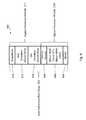
- FIG. 4is a diagrammatic representation of factors used to determine the total end-to-end path delay in accordance with the present invention.
- FIG. 5is an exemplary APN with geographically diverse network control nodes (NCNs) in accordance with the present invention
- FIG. 6is a primary NCN state machine in accordance with the present invention.
- FIG. 7is a secondary NCN state machine in accordance with the present invention.
- FIG. 8is a client state machine in accordance with the present invention.
- FIG. 9is an exemplary high availability APN with geographically diverse network control nodes (NCNs);
- FIG. 1 OAillustrates an APN configuration with a primary NCN site and a client and secondary NCN site, each NCN site coupled to sixteen APN conduits to sixteen APN client nodes in accordance with the present invention
- FIG. 10Billustrates an APN configuration with a primary NCN site and a client and secondary NCN site, each NCN site coupled to sixteen APN conduits across a WAN to sixteen APN client nodes after a failure in the network splits the APN, represented by a dashed line, into two separate networks in accordance with the present invention.
- the present inventionis directed towards providing a flow-based, reliable, high-bandwidth network comprised of multiple paths between sites.
- FIG. 1shows an example of an adaptive private network (APN) 100 in which the present invention may be suitably employed as described in further detail below, including the network components, flows, paths, and services.
- the APN 100includes one or more wide area networks (WANs), such as WAN 102 , APN appliances 104 - 106 , WAN routers 110 1 - 110 3 , and network application services as well as APN conduits between APN appliances, as described in more detail below.
- WANswide area networks
- An APN pathis a logical connection established between two WAN links located at different geographic sites across a WAN.
- An APN conduitis a virtual connection between two APN nodes, formed by aggregating one or more APN paths and their allocated WAN link resources.
- An APN applianceis a device that contains APN node functionality including all software modules within.
- a WAN linkrepresents a physical access point to the wide area network (WAN), such as a digital subscriber line (DSL) connection or a cable modem.
- WANwide area network
- DSLdigital subscriber line
- the distinctive characteristic of a WAN linkis the bandwidth, or in other words, the amount of data capacity available for transmission and reception.
- WAN linkscan be shared among APN conduits, and intranet and Internet network services.
- the APN appliancesdo not directly attach to WAN links.
- APN appliancescommunicate with WAN links through logical connections, such as the WAN routers 110 1 - 110 3 of FIG. 1 .
- a private WAN linkprovides a physical access point to non-public WAN destinations.
- Examples of such private WAN linksinclude an asynchronous transfer mode (ATM) link with an ATM virtual circuit, a frame relay link with a frame relay circuit, a multiprotocol label switching (MPLS) tunnel, a virtual private network (VPN) tunnel, or a leased point-to-point line.
- ATMasynchronous transfer mode
- MPLSmultiprotocol label switching
- VPNvirtual private network
- Connectivity on a network having a private WAN linkis made to a private list of destinations on the other end of the network.
- a public WAN linkrepresents a physical access point to the Internet. It can be assumed that any public WAN link can establish a connection to any other public WAN link.
- An APN serviceis a set of processing steps performed on packets that are transmitted through the APN. As illustrated in FIG. 1 , data traffic that moves through APN 100 and APN appliance 106 may require different types of services depending on where the sending and receiving stations are located.
- An APN service instanceis a particular configured contextual instance of an APN service held in an APN appliance memory 107 internal to the APN appliance 106 , for example.
- An APN service instance's memorycontains, but is not limited to, context specific configuration data, statistical data, and tracking states data.
- an APN nodemay have multiple APN conduits that connect to remote APN nodes. For each APN conduit there exists a separate APN service instance for the APN conduit service type.
- An APN conduit service associated with path 112manages network traffic packets that are transmitted through the APN 100 from the APN appliance 105 through router 110 1 , through the WAN 102 , through another router 110 3 to APN appliance 104 .
- the APN conduit service for path 112operates on both APN appliances 104 and 105 .
- the APN conduit servicesends and receives data between a first geographic location that has an APN appliance 105 and a different geographic location that has an APN appliance 104 utilizing the full benefits provided by the APN conduit service for WAN resource allocation and network adaptation.
- An APN intranet service associated with path 114is used to manage the sending and receiving of data between a first geographic location that has the APN appliance 105 and a different geographic location within an enterprise non-APN site 120 that does not have an APN appliance by way of a WAN link that is also utilized by other APN services.
- an APN intranet servicesuch as the one associated with path 112
- An APN Internet service associated with path 116is used to send and receive data between a first geographic location that has the APN appliance 105 and a different geographic location that is external to an enterprise network by way of a WAN link that is also utilized by other APN services.
- traffic using the APN Internet servicemay be associated with a network user accessing a public Internet web server 122 .
- An APN pass through service 118is used to send and receive data between a first geographic location that has an APN appliance 105 and a local site 124 within the same first geographic location.
- an APN pass through servicemay be used to send and receive data between a first geographic location that has the APN appliance 105 and different geographic location within an enterprise network that does not have an APN appliance and does not traverse the WAN using any WAN links associated with any other APN services.
- FIG. 2Aillustrates an APN conduit 2 -ended service 200 between a primary NCN control node 202 and a client and secondary NCN 204 according to the present invention.
- the client and secondary NCN 204is configured to operate as a client node.
- the client and secondary NCN 204may also be configured for an alternative operation as a secondary NCN is described in further detail below.
- Each APN nodecontains a collection of software modules which govern its participation within an APN.
- the software modules for the control node 202 and the client and secondary NCN 204include control plane modules 210 and 230 , WAN ingress processor modules 212 and 234 , and WAN egress processor modules 214 and 232 , respectively. As illustrated in FIG.
- the WAN ingress processing modules 212 and 234includes conduit services 220 and 222
- WAN egress processing modules 214 and 232includes a duplicate conduit service 224 and 226 .
- Intranet service, Internet service, and pass through serviceare also provided at each APN node.
- Each APN service type, including conduit, intranet, Internet, and pass through service types,implements processes for each type of data traffic that is communicated to and from the WAN respectively.
- APN conduit trafficflows through two APN nodes 202 and 204 as the traffic traverses the APN.
- WAN ingress processing module 234 of APN client and secondary NCN 204performs the WAN ingress conduit service processing 222 prior to transmitting the traffic 206 via the WAN 211 to the APN control node 202 .
- WAN egress processor module 214 of the APN control node 202performs the WAN egress conduit service processing 224 prior to transmitting the traffic 206 to the node or nodes located on LAN 240 .
- the binding of the one APN node's WAN ingress conduit processing 222 to the peer APN node's WAN egress conduit service processing 224constitutes an APN conduit in which traffic is actively monitored and managed across multiple WAN resources.
- the APNis capable of using disparate asymmetric WAN links which vary in behavior of bandwidth, latency, jitter, packet loss and congestion frequently over time.
- the APNcan use an asymmetric DSL WAN link that transmits data at 512 kbps upstream to the WAN and 6 mbps from the WAN through the public network combined with a private symmetric leased circuit T1 WAN link that transmits data at 1544 kbps upstream and downstream and a cable broadband connection that transmits data at 312 kbps upstream to the WAN and 3 mbps from the WAN to a peer having adequate aggregation bandwidth of these rates for a single TCP file transfer session at a theoretical transmit rate of 2368 kbps and receive at 10544 kbps.
- the actual ratewould approach 90% of these rates. If the behavior of the connection was to change, for example the paths to the DSL link were to have dramatic levels of loss, the APN would, using its high frequency performance feedback mechanism, adapt the network to avoid or mitigate the issues by using alternative resources or attempting to recover from the loss.
- the APN node's software modules at a siteare stored and operate in the same physical APN appliance; however, the modules may also exist in separate physical APN appliances in alternative embodiments.
- the methods described in connection with the embodiments disclosed hereinmay be embodied directly in one or more software modules executed by a processor and memory complex such as a personal computer, a server, or the like having one or more central processing unit devices.
- the processor and memory complexmay be configured to execute instructions under control of a software module program stored on a computer readable non-transitory storage medium either directly associated locally with the processor and memory complex, such as may be available through an instruction cache, or accessible through an I/O device.
- a software modulemay reside in a computer readable non-transitory storage medium which may include random access memory (RAM) memory, flash memory, ROM memory, dynamic random access memory (DRAM), synchronous dynamic random access memory (SDRAM), read only memory (ROM), programmable read only memory (PROM), erasable programmable read only memory (EPROM), electrically erasable programmable read only memory (EEPROM), hard disk, a removable disk, a CD-ROM, digital video disk (DVD), other types of removable disks, or any other suitable non-transitory storage medium.
- RAMrandom access memory
- DRAMdynamic random access memory
- SDRAMsynchronous dynamic random access memory
- ROMread only memory
- PROMprogrammable read only memory
- EPROMerasable programmable read only memory
- EEPROMelectrically erasable programmable read only memory
- hard diska removable disk
- CD-ROMcompact disc-read only memory
- DVDdigital video disk
- DVDdigital video disk
- the WAN ingress processor module 212may suitably be embodied as software and hardware components responsible for processing network traffic for transmission from a local area network (LAN) to a WAN.
- the WAN egress processor module 214may suitably be embodied as software operating on hardware components, such as a processor and memory complex that is responsible for processing network traffic for transmission from a WAN to a LAN.
- WAN ingress and WAN egress processor modulesare discussed in further detail below.
- the APN node's control plane module 210may suitably be embodied as software operating on hardware components, such as a processor and memory complex that utilizes the APN node's WAN ingress processor module 212 and WAN egress processor module 214 as the means for transmitting and receiving APN node to APN node control data across the WAN.
- FIG. 2Billustrates an APN time synchronization transaction 248 between an APN client and secondary NCN 204 and an APN control node 202 according to the present invention.
- a secondary NCNbecomes the active NCN due to a failure at the primary NCN site or a failure of the conduit between the primary NCN and secondary NCN, the APN is recalibrated to the master clock in the secondary NCN.
- a network control node (NCN) module 250is an administration point for an APN.
- the NCN module 250resides within the APN control node 202 .
- the APN control node 202represents an APN node that also performs as the network control point of the APN.
- an NCN modulesuch as NCN module 250 , resides in an appliance that is separate from an APN node and administers and controls the APN nodes within the APN.
- the NCN module 250provides administrative support and control to the APN, including but not limited to, distribution of configuration objects to APN client nodes and time synchronization to the APN.
- multiple NCNsare provided for redundancy purposes to avoid having a single point of failure in an APN.
- the APN client and secondary NCN 204is an APN node that can perform as a client node and the secondary APN NCN control point. It performs as an APN client point that works in tandem with an external APN control point for the APN node's control and administration or as the APN node's control point when the primary NCN 202 fails.
- APN control pointOne purpose of the APN control point is to establish and manage APN conduits between APN nodes across a WAN for intra-enterprise site-to-site communications.
- a particular APN control nodemay administer and have conduits to multiple APN client nodes.
- an APN control nodeis located in the data center of an enterprise. In such an embodiment, the APN control node administers conduits to and from the data center. In another embodiment, the APN control node may also administer conduits directly from APN client node to APN client node.
- An APN client nodeis an APN node that exists remote from an APN control point. Although an NCN will potentially have multiple APN network client nodes, each APN network client node will preferably have one active NCN. In one embodiment, APN client nodes will have practically no need for local administration. Generally, APN client nodes will be located at remote branch offices.
- the synchronization of control information from the single APN control point of an APN to one or more APN client pointsis one aspect of maintaining the proper behavior of the APN in general.
- An APN clock and APN configuration synchronization transactions between APN control points and APN client pointsare transactions discussed immediately below in greater detail.
- a master APN clock 249is synchronized throughout all APN client nodes, such as client and secondary NCN 204 , within an APN.
- An APN clock sync server 254synchronizes timing throughout APN nodes, such as APN client and secondary NCN 204 , in the APN.
- a hardware real time clockis contained within an APN appliance of the APN control node 202 , such as appliance 104 shown in FIG. 1 . This clock is used as an APN reference clock for the APN and is referred to as the master APN clock.
- Each APN client pointsolicits and calibrates to the APN clock sync server 254 , residing within the APN control point specific NCN module 250 , on an APN control node 202 .
- Each APN client nodesuch as APN client and secondary NCN 204 , also contains a hardware real time clock 261 within the client and secondary NCN 204 's APN appliance, such as appliance 105 shown in FIG. 1 .
- This APN client clock 261is referred to as the APN client clock.
- the time synchronizationis such that drift between the APN nodes, for example, is limited to a drift of about a few milliseconds. In a presently preferred embodiment, empirical study validates that the drift range is about 1.5 milliseconds.
- the master high resolution APN master clock 249is kept at the APN control point and each APN client point synchronizes to this clock.
- Each APN client nodesuch as client and secondary NCN 204 , sends an APN clock sync sample request message 260 to the APN control node 202 to request the current time.
- the request message 260is received in the APN control node and initiates a process that responds to the request message 260 by sending the current time back to the APN client node in an APN time sync sample reply message 259 .
- the APN client nodemeasures the time from initiating the request, T0, to receiving the current time response, T1.
- the APN client nodeuses this timing data to adjust a network time by using a linear algebraic calculation based on the slope-intercept form.
- yis the time at the APN control node and x is the client node local time
- bis the base offset between the two
- mis the rate of change of y versus x which is the slope.
- the slopeis calculated by taking two samples over a pre-specified period and averaging the samples together.
- the base offsetis calculated by taking the difference of the value between the network control point time and the client time, adjusted for one half round trip time (RTT).
- time sync sample tablesare defined below.
- Finite impulse response filter tables for slope and baseare kept as well.
- a table containing 128 entriesis used to track time sync samples.
- Each time sync samplehas two fields per record; the APN network time from the network control point, and the local time plus one-half RTT.
- every entry in the time sync sample tableis initialized with the value of the first sample of APN time and local time. Each subsequent sample entry is advanced in the table eventually rotating through all entries circularly.
- the time sync sample tableis then used to derive a slope sample by dividing the time deltas of the current entry in the time sync table and the oldest entry in the rotating table for the APN network time and the local time.
- the slope sampleis equal to the change in APN network time divided by change in APN client local time for the duration of the table, which is the time between the current and the oldest entry in the table.
- this time sync tableitself is not a finite impulse table, since an average sum for a sum of all the elements in the table is not used, but rather a slope between two points in time that are 126 sample entries apart is utilized. It will be recognized that different numbers of table entries and spacings may be employed, and that the example described is illustrative and not limiting.
- a finite impulse response table for slopecontains 64 entries. Initially, every entry in this slope table is initialized to one, meaning the rate of change of the APN network time is defaulted to the rate of change as the local time.
- slope entriesAs slope samples are derived from the time sync sample table, actual slope entries displace the defaulted slope entries. Similar to the sample table, the slope table is a circular table where each entry advances. Each subsequent sample entry is advanced in the table eventually rotating through all entries circularly. A sum of all the slopes in the slope table is maintained using all the entries in the slope table. Each time a new entry is added, the sum is recalculated by subtracting the value of the entry removed and adding the value of the new entry.
- a base sample tablecontains 256 entries. This table is not actually used to determine the base that will be used for APN time, but instead is used to determine the acceptability of the last time sync sample to be used for resetting the base and slope.
- Each entry in the base sample tablecontains two fields, a value field and a period field.
- the value fieldcontains a difference between the value of local time plus one-half RTT in local time and the value of APN network time.
- the period fieldcontains the time period duration between this sample time and the prior time sync sample time. This results in a table that has a time span that covers the time from the first entry to the last entry. A sum is continually calculated on both the value and period fields for all entries in the table.
- the softwarethen begins to use the base table to determine acceptability filters.
- the sum of the value fields in the base tableis divided by the sum of the period fields in the table. This value is the average rate of change of the base for the base table over the time period. In a current implementation, this value is adjusted for change per second.
- the base offset in APN clock sync client and calibration module 255is not acceptable for adjustment if each of the following is true:
- the formula for updating the slopeis the sum of the slope table entries divided by the number of slope table entries.
- the formula for updating the baseis the APN network time ⁇ (client local time+1 ⁇ 2 RTT)*slope.
- FIG. 3illustrates an APN 300 having an APN network control node (NCN) 202 coupled through sixteen APN conduits to sixteen APN client nodes according to the present invention.
- APN 300is centrally configured.
- a network administratorconfigures the entire APN 300 through an APN configuration file that is processed by the NCN module 250 .
- the NCN module 250then distributes the configuration settings to all client nodes in the APN 300 .
- This method of configuring the APN 300is intended to provide benefits to the administrator by providing a single point of configuration to the network. It also assures configuration consistency and compatibility for all APN nodes in the network simultaneously, with strict version checking.
- an intensive configuration audit and validationis done to the configuration prior to that configuration being applied to the network.
- This auditgreatly decreases risks of invalid configurations being placed on the production network.
- the central configurationalso provides for additional configuration bandwidth optimization for the network, by doing a holistic mapping of the APN resources and their initial allocations.
- the centralized configurationcan provide information and warnings to the administrator as to the behavior of the configuration that may not be obvious or intended from the configuration, before loading the configuration onto a production network.
- FIG. 2Cillustrates APN configuration transactions 272 and 274 between an APN client and secondary NCN 204 and an APN control node 202 according to the present invention.
- the APN control point specific NCN module 250may perforin APN configuration push process 272 , as described below, to initiate the sending of a new configuration.
- One of the APN client nodes, such as client and secondary NCN 204may send an APN configuration version report 274 to the APN control point NCN module 250 , which causes the NCN upon detecting a mismatch to initiate the transfer of the correct configuration to the client node.
- a new configurationmay be uploaded directly through an administrative web interface console software program residing within every APN node, shown as software interfaces 276 and 278 in FIG. 2C . Additionally, a quick start version of the configuration may be used as well.
- APN configuration push process 272When an APN configuration push process 272 is initiated, a message is sent from an APN master configuration server 258 to an APN client configuration agent 257 to indicate that an update is available.
- the APN client configuration agent 257replies with a request for a data block of the configuration file 274 and the APN master configuration server 258 responds to the request by sending the requested data block 272 containing, for example the first 800 bytes of the configuration file to the APN client configuration agent 257 .
- the client nodeissues multiple requests for file blocks in parallel, up to some predefined limit. The limit for parallel requests in progress scales up and down based on detection of loss in the network.
- a preset time limitsuch as 800 to 1000 milliseconds (ms)
- the APN master configuration server 258If a preset time limit, such as 800 to 1000 milliseconds (ms), has passed and the APN master configuration server 258 has not received an ACK 274 , it will retransmit the packet. This process continues until all packets have been successfully transmitted or the APN master configuration server 258 transmits a packet ten times, for example, without receiving an ACK.
- the transport layer of softwarestops any more retransmissions and a higher layer of the software takes over. For example, clients may scale down the number of parallel block requests and possibly reissue the initial request for that block.
- APN control point NCN module 250 of FIG. 2Ccontains all the configuration files for the sites in the network, an update may be manually performed using these files.
- administrative interfacessuch as interfaces 276 and 278 , a file or files containing all configuration registries and all software packages for each site in the APN is downloaded from the APN control point NCN module 250 .
- the APNwould distribute all client site software packages to the secondary NCN site using control messages.
- the APN control point NCNcan also generate a specific client site configuration that can be downloaded to the client module 251 via the client administrative interface 276 .
- the APN services on the APN client and secondary NCN 204are then applied or restarted, depending on the type of configuration changes received, thus bringing the APN client node configuration into synchronization.
- an APN configuration request 274the control plane module 230 of the APN client and secondary NCN 204 indicates that it has received an APN quality report from the APN control point NCN module 250 with a configuration version that does not match the current configuration of the APN client and secondary NCN 204 .
- An APN configuration request 274is sent to the APN master configuration server 258 which will verify that it has an updated configuration for the APN client and secondary NCN 204 and initiates an APN configuration push process 272 as described above. If the APN client and secondary NCN 204 no longer exists in the new APN configuration, the APN configuration request 274 will be ignored.
- APN conduitsmay exist between the NCN and for example sixteen APN client nodes as shown in FIG. 3 , for example, although there is no systemic limit to the number of potential APN client nodes.
- Each APN conduitmay have the unique configuration parameters tailored by an administrator for the particular needs of each geographic location associated with a particular APN.
- APN path statesFor a definition of APN path states, a description of path processing services is provided below. Any paths currently in a path quality good state are eligible to be chosen first. If multiple paths are in a path quality good state, then an estimated end to end time is evaluated and compared for each path. If no path is in path quality good state, then a path with the highest bandwidth path quality bad state is chosen.
- FIG. 4is a diagrammatic representation of factors 400 used to determine the total end-to-end path delay according to one embodiment of the present invention. Such factors determine an estimated end-to-end time in an evaluation process of a best path as compared to other alternative paths.
- the term “one way time” (OWT)refers to the amount of time it takes for a packet to traverse a network from source to receiver. In the context of this invention, the one way time is measured by subtracting the receive time stamp from a WAN egress module 214 from the send time stamp from a WAN ingress module 212 , FIG. 2A .
- the term “best one way time” (BOWT)refers to the lowest measured OWT for a particular packet on a particular path over a period of time.
- the evaluation processchooses one best path based on path latency which is calculated using a best one way time (BOWT) 404 , mean WAN jitter 406 , latency penalty for short term instability 408 and WAN link scheduler's queue delay times 410 and 412 , with additional preferential treatment referred to as impedance 414 applied to any prior primary path for the APN traffic flow, if a primary path exists.
- BOWTbest one way time
- an exemplary formula for estimating total end-to-end path delayis the BOWT 404 +(mean WAN jitter 406 )+3*( ⁇ (mean WAN jitter 406 ))+latency penalty 408 +local WAN link scheduler queue delay 410 +remote WAN link scheduler queue delay 412 +impedance 414 .
- the BOWT 404 , mean WAN jitter 406 and latency penalty 408are provided by a remote APN conduit state resulting from control messaging from the egress processor module 214 of FIG. 2A , while the local WAN link scheduler queue delay 410 , remote WAN link scheduler queue delay 412 and impedance 414 are provided by the WAN ingress processor module 212 of FIG. 2A .
- Impedanceis employed as the present invention recognizes that a typical queuing system follows a Poisson distribution.
- a typical queuing systemhas a statistical probability curve that, when plotted on a chart, is highly slanted to the left, with potentially long tail to the right.
- the probability equation to determine the ⁇ 99% path delay timeis very sound, it is also important of note that any probability is not a certainty.
- sending a packet on a particular stable pathwill typically with ⁇ 99% certainty result in the packet arriving at or before a statistical jitter calculation, when the packet arrives before the ⁇ 99% time is much less certain.
- an APNconfigured for high availability with a node site configured with an active network control node and a secondary network control node. Redundancy at this site is achieved by having the secondary control node take over as the NCN if problems develop. However, this configuration provides no redundancy for the node site itself. For example, if that site were to become unavailable due to a natural disaster, due to severe network outages or some other cause, then there would be no NCN to manage the APN. In such an event, in accordance with the present invention one or more sites may serve as an NCN if a primary NCN site becomes unavailable.
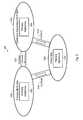
- FIG. 5is an exemplary APN 500 with geographically diverse network control nodes (GDNCNs) in accordance with the present invention.
- the exemplary APN 500is configured with three sites 502 - 504 , which are selected to be located remotely from each other.
- a sitewould be defined as remote if the devices are physically in different locations such as different buildings, cities, states, time zones or countries.
- a primary NCN site 502may be located in a company's headquarter location in a first country
- a client and secondary NCN site 503may be located in second country
- a client site 504may be at some location inter mediate between the two other sites.
- An APN applianceis a device that contains APN node functionality according to software modules, such as the control plane module 210 and 230 , the WAN ingress processor module 212 and 234 , and the WAN egress processor module 214 and 232 , as described in more detail above with reference to FIG. 2A .
- the three sites 502 - 504are coupled by conduits 514 - 516 and each of the three conduits provides a configurable virtual connection between two connected APN appliances.
- the exemplary APN 500is also configured with two sites that can serve as an active NCN for the APN.
- an APN with geographically diverse NCNsmay support as many client sites as are required for the APN and not limited by having one or more geographically diverse NCNs.
- the configuration of any site for high availabilityis optional and will be discussed in more detail with regard to FIG. 9 .
- the primary NCN site 502is an APN site that is configured to be a default active NCN providing NCN functionality for the APN 500 .
- the client and secondary NCN site 503is an APN site that is configured to be a default secondary NCN providing capability to take over the role of the NCN as needed for the APN 500 and also operates as a client site when in standby NCN mode. With multiple sites, such as a plurality of client sites in the APN, the primary NCN site 502 and the secondary NCN site 503 are both required to have conduits to all sites in the APN.
- An active-secondary (A-S) conduitis a conduit between a primary NCN and a secondary NCN.
- Active-client (A-C) conduitsare a set of conduits between an active NCN and client nodes.
- Whether a secondary NCN site is triggered to start a transition process to taking over the role of an active NCN for the APNis determined by examination of a change in APN state information, such as conduit states based on a threshold. If a conduit is functioning at or above a quality communication threshold, the conduit is considered, for the purposes of determining NCN state, in a good conduit state. If the conduit is functioning below the quality communication threshold, the conduit is considered, for the purposes of determining the NCN state, in a bad conduit state effectively turning the conduit off. It is noted that even if two or more NCNs became active NCNs, there would be no network outage since no resource is shared between two active NCN sites.
- the configuration information for the APNis separately stored in both the primary NCN site and the secondary NCN site.
- the networkcan become physically separated and operate as two separate networks in this mode until the problem is repaired or the two separate networks are reconfigured back to a single APN with the primary NCN in control.
- the APN 500distinguishes between a primary NCN site, such as site 502 , and a secondary NCN site, such as site 503 .
- the APN 500is configured with the primary NCN site 502 to always be the preferred active NCN for client nodes.
- the secondary NCN site 503transitions to active NCN functionality upon detecting the change in APN state information, such as the conduit 514 to the primary NCN site 502 is down.
- Client site 504may still treat the primary NCN site 502 as the active NCN if the conduit 516 to the primary NCN site 502 is up.
- Client site 504treats the secondary NCN as the active NCN if the conduit 516 to the primary NCN site 502 is down and the conduit 515 to the secondary NCN site 503 is up and receiving control messages from the NCNs.
- the active NCNwhether it is functioning on the primary NCN site 502 or on the secondary NCN site 503 , provides interfaces to the client site 504 in the same way shown in FIGS. 2B and 2C .
- the active NCNkeeps the network time for the APN and distributes timing information to remote sites for periodic calibration tuning of timing at the remote sites, as described in more detail above with regard to FIG. 2B .
- the active NCNalso monitors remote sites for having the latest software and registry versions and corrects any mismatches identified.
- the secondary NCNis synchronized to the new configuration.
- a secondary NCNis configured to perform all functions of a client node for normal data transfer operations.
- Client appliancessuch as primary appliance 510 are configured to determine which NCN is the active NCN based on the state of the conduits 516 and 515 to the primary and secondary NCN sites, respectively. If a conduit 516 to the primary NCN site 502 is available for at least a preset time period, such as five minutes, the client site 504 selects the primary NCN site 502 as having the active NCN. In this case, the client site 504 selects the secondary NCN site 503 as having the standby NCN function even though the secondary NCN site 503 may also be configured as having an active NCN or to operate as a client site.
- the client site 504selects the secondary NCN site 503 as having the active NCN.
- Client sitesgenerally ignore NCN to client control messages that originate from a standby NCN site.
- APN operationif a version mismatch of software or a new APN configuration is determined at the primary NCN or at the secondary NCN, the site with the more current or latest software or the latest configuration is considered the active NCN.
- the secondary NCN site 503takes over as the active NCN for the APN 500 while the primary NCN site 502 is down. Such a situation may occur, if the secondary NCN site 503 determines the conduit 514 is inoperative for a programmed time period, such as fifteen seconds. With the primary NCN site 502 or conduit 514 down, the secondary NCN site 503 switches to become the active NCN for the APN. While operating with the secondary NCN site 503 as the active NCN, software updates and network configuration changes may be completed which would most likely change the configuration information stored in the active NCN, which in this case is the secondary NCN site 503 .
- the primary NCN site 502After the primary NCN site 502 is restored, the primary NCN site 502 must be updated with the configuration and software change information from the secondary NCN site 503 .
- the restored primary NCN site 502checks with the currently active NCN operating on the secondary NCN site 503 and determines there is a mismatch with the software version and that the configuration of the APN has been updated.
- the primary NCN site 502yields control to the secondary NCN site 503 and the primary NCN site 502 operates as the standby NCN. With the primary NCN site 502 in standby mode, the secondary NCN is configured to push the updated configuration and software updates to the primary NCN site 502 .
- the primary NCN site 502switches from standby mode to active mode and the secondary NCN site 503 switches from active mode to standby mode.
- a timer mechanismensures the transitions occur safely. Once the primary NCN has been updated, it will take over operation after being active for a preset period of time, such as 5 minutes. It is noted that the act of changing the location of the active NCN does not impact communication traffic in the APN because the configuration information for the APN remains the same in both the primary NCN site 502 and the secondary NCN site 503 at the time of the transition and the active NCN does not interfere with communication traffic due to a change in the active NCN site.
- FIG. 6is a primary NCN state machine 600 in accordance with one aspect of the present invention.
- the primary NCN state machine 600operates at predetermined intervals, such as every second, to check the APN system for any events, such as a change in APN state information, that require an action to be taken.
- State machines of the present inventionare preferably implemented in processor code with states stored in memory of the processor, though in an alternative implementation the state machines may be implemented by a circuit with feedback to and under control of a processor.
- the primary NCN state machine 600is comprised of three states 602 - 604 and transitions 605 - 609 between the states.
- An initialization event 605places the primary NCN site in the primary active state 602 .
- Initialization eventsmay include power on of the primary NCN site or a restart operation, such as may occur during software updating.
- the state machine 600takes transition 606 to place the primary NCN site in the primary standby state 603 .
- a software version, a configuration, or bothare updated on the out-of-date primary NCN site.
- the software version on the primary NCN siteis updated, but the new version that was installed still doesn't match the software version on the secondary site. This is usually the case when the newly installed software becomes the most current version and now the software version on the secondary site is out of date.
- the state machine 600takes transition 607 from primary standby state 603 to takeover time wait state 604 .
- a takeover timeris started, which is set for a predetermined period, such as five minutes.
- an update to the secondary NCN site 503is installed and it may be at a more current level than what was installed in the primary NCN site causing the state machine 600 to take transition 608 back to the primary standby state 603 .
- the state machine 600takes transition 607 back to the takeover time wait state 604 and the takeover timer is restarted.
- the state machine 600takes transition 609 back to the primary active state 602 and the primary NCN site 502 is back operating as the APN's active NCN.
- the predetermined wait timesuch as the exemplary 5 minute wait time, is used to be sure the primary NCN site 502 is stable. While the primary site 502 is in the takeover time wait state 604 , the secondary site is still in a secondary active NCN state and in charge of APN operations.
- FIG. 7is a secondary NCN state machine 700 in accordance with the present invention.
- the secondary NCN state machine 700operates at predetermined intervals, such as every second, to check the APN system for any events, such as a change in APN state information, that require action to be taken.
- the secondary NCN state machine 700is comprised of three states 702 - 704 and transitions 705 - 709 between states.
- An initialization event 705places the secondary NCN site in the secondary standby state 702 . Initialization events may include power on of the secondary NCN site or a restart operation, such as may occur during software updating. If an A-S conduit, such as conduit 514 of FIG.
- a takeover timermay be set to a first predetermined time, such as fifteen seconds if the transition 706 was due to determining the A-S conduit is down or may be set to a second predetermined time, such a five minutes if the transition 706 was due to determining the software versions or configuration information is more current on the secondary NCN site. It is noted that the first predetermined time and the second predetermined time are not related and set according to the particular requirements of the associated APN.
- While in the takeover time wait state 704if the A-S conduit is determined to be back up or it is detected that the primary NCN site has upgraded the software and or configuration information to be at the most current level or matches the software and configuration on the secondary NCN site, the state machine 700 takes transition 707 back to the secondary standby state 702 . Returning to state 704 , if the secondary NCN site detects that a takeover timer has expired, the state machine 700 takes transition 708 to the secondary active state 703 .
- the state machine 700takes transition 709 back to secondary standby state 702 .
- FIG. 8is a client state machine 800 in accordance with the present invention.
- the client state machine 800operates at predetermined intervals, such as every second, to check the APN system for any event that requires an action to be taken.
- the client state machine 800comprises four states 802 - 805 and transitions between the states. States of the conduits to the primary NCN site, such as conduit 516 , and the secondary NCN site, such as conduit 515 , are monitored to determine which of the two sites is the active NCN.
- An initialization event 806places the client site in a primary active state which represents that the primary NCN site is the active APN NCN. Initialization events may include power on of the client site or a restart, such as a restart due to a software upgrade.
- the state machine 800takes transition 808 to a secondary pending state 803 and a takeover timer is started. Prior to the takeover timer expiring, if the client site determines the conduit to the primary NCN site is back up, the state machine 800 takes transition 810 back to the primary active state 802 . Returning to the secondary pending state 803 , if the takeover timer expires, the state machine 800 takes transition 812 to a secondary active state 804 , which represents that the secondary NCN site is the active APN NCN.
- the state machine 800takes transition 814 to a primary pending state 805 and a second takeover timer is started. Two timers are utilized, but generally only one is active. For example, the primary to secondary timer may be set as the 15 second timer whereas the secondary to primary timer may be set as the 5 minute timer. Prior to the second takeover time expiring, if the client site determines the conduit to the primary is back down and the conduit to the secondary is still up, the state machine 800 takes transition 816 back to the secondary active state 804 . Returning to the primary pending state 805 , if the second takeover time expires, the state machine 800 takes transition 818 back to the primary active state 802 , which represents that the primary NCN site is back to being the active APN NCN.
- an APN appliancechanges from active NCN to standby NCN or standby NCN to active NCN, the APN appliance is required to reinitialize its time synchronization. Such time synchronization is accomplished in the manner described with regard to FIG. 2B . Any time synchronization control messages received during the time synchronization period may not be valid and are dropped. In such a situation with a transition of the secondary NCN site making a transition to the active state, the secondary NCN reestablishes the network time using its own local clock and messages may be retransmitted. It should be noted that the control and WAN ingress and egress processor modules can operate independently. Time control messages can be dropped while packets continue to flow during time synchronization.
- FIG. 9illustrates an exemplary high availability APN 900 with geographically diverse network control nodes (NCNs).
- Each site 902 - 904is organized in a high availability configuration with a primary appliance 906 , 908 , and 910 and a secondary appliance 907 , 909 , and 911 , respectively.
- the high availability APN 900provides reliable operation at a node site even with a failure of a primary appliance.
- Both the primary NCN site 902 and the client and secondary NCN site 903synchronize updates to configuration and code libraries with any high availability pairs of appliances, such as primary appliances 906 , 908 , and 910 and secondary appliances 907 , 909 , and 911 .
- the communication between NCN sitesutilizes the same communication protocol utilized for communications between any two nodes as in the APN 500 and does not require any additional messages or change in any fields in a message to support high availability operations between sites. If the primary NCN site 902 has a failure and the APN 900 switches to the secondary NCN site 903 , the primary appliance 908 takes over the NCN role. If the primary appliance 908 also has a failure, the active NCN operations switch to the secondary appliance 909 .
- the current invention as describedprovides for three levels of failure protection. If the primary appliance 906 fails, the secondary appliance 907 would take over as the active NCN (level 1). If the secondary appliance 907 then fails, the client and secondary NCN site 903 , primary appliance 908 would take over as the active NCN (level 2). If the primary appliance 908 were to fail, the secondary appliance 909 would take over as the active NCN (level 3). Extending the current invention to support multiple secondary NCN sites could be done by modifying the state machines 600 , 700 and 800 to support a priority attribute. In an event of a failure, the next highest priority secondary NCN site would take over as the active NCN. The priority attribute could be exchanged with the client site notes or could be based off the lowest IP address of each secondary NCN site node.
- FIG. 10Aillustrates an APN 1000 configuration with a primary NCN site 1002 and a client and secondary NCN site 1003 , each NCN site is coupled to sixteen APN conduits across WAN 1001 to sixteen APN client nodes 1003 and 1004 - 1018 in accordance with the present invention.
- Timing in the client nodes 1003 and 1004 - 1018has been calibrated to a master clock in the primary NCN site 1002 .
- the primary NCN state machine 600 , the secondary NCN state machine 700 , and the client state machine 800are in operation at the same time.
- the primary NCN site 1002is the active NCN and the client and secondary NCN site 1003 is operating as a client. No failures have been detected and the APN 1000 is operating normally.
- FIG. 10Billustrates an APN 1050 configuration with a primary NCN site 1002 and a client and secondary NCN site 1003 , each NCN site is coupled to sixteen APN conduits across WAN 1001 to sixteen APN client nodes 1003 and 1004 - 1018 after a failure in the network splits the APN 1050 , represented by a dashed line 1019 , into two separate networks 1020 and 1021 in accordance with the present invention.
- a disastercould remove all connectivity between a primary and secondary NCN as illustrated by the dashed line 1019 .
- the state machine 600stays in state 602 and identifies that due to an event the number of client nodes has changed and only the nodes 1004 - 1012 represented by the split APN 1020 are still present.
- the secondary NCN state machine 700identifies that due to the failure the conduit to the primary NCN has failed.
- the secondary NCN state machine 700takes transition 706 to takeover time wait state 704 and after the takeover timer expires takes transition 708 to secondary active state 703 .
- the client and secondary site 1003becomes the active APN NCN for the second split APN 1021 with client nodes 1013 - 1018 .
- the first split APN 1020 and the second split APN 1021operate and can be rejoined once connectivity has been returned between the two split networks.
- any code or configuration changeswill be automatically synchronized.
- the state machines 600 , 700 , and 800are configured to also take into account typical administrative tasks required by a network operator and or equipment being managed. Such administrative tasks are not treated as failure events. For example, configuration changes on an appliance or node do not falsely activate failover operation from a primary active NCN to a secondary NCN or put the APN system in a constant state of thrashing between primary and secondary nodes. Changes between local node primary and secondary appliance configurations as identified in 900 also do not falsely activate a failover operation. Such thrashing between primary and secondary NCN nodes is avoided by use of the timers described above which provides time for operations at the primary and secondary nodes and at the primary and secondary appliances to complete and return to a stable operating state.
- Software packages for an APNare distributed and managed in a similar manner as the APN control point NCN module 250 of FIG. 2C uses to manage configuration files.
- files containing software packages for the sites in the APNmay be downloaded using interface 278 to the APN control point NCN module 250 .
- the APN primary NCN 502 as in FIG. 5will distribute all client site software packages to the secondary NCN 503 site using control messages.
- the client sites and secondary NCN sitescan also be updated locally by downloading client software packages to the client module 251 via the client administrative interface 276 .
- the APN services on the APN client and secondary NCN 204are then restarted thus bringing the APN software node configuration into synchronization.
Landscapes
- Engineering & Computer Science (AREA)
- Computer Networks & Wireless Communication (AREA)
- Signal Processing (AREA)
- Theoretical Computer Science (AREA)
- General Engineering & Computer Science (AREA)
- Quality & Reliability (AREA)
- Physics & Mathematics (AREA)
- General Physics & Mathematics (AREA)
- General Health & Medical Sciences (AREA)
- Health & Medical Sciences (AREA)
- Computer Hardware Design (AREA)
- Computing Systems (AREA)
- Medical Informatics (AREA)
- Cardiology (AREA)
- Computer Security & Cryptography (AREA)
- Data Exchanges In Wide-Area Networks (AREA)
Abstract
Description
- 1. If the absolute rate of change of the last sample is greater than the absolute value of the average rate of change for the base table plus or minus three times the square root of that rate of change.
- 2. If the period covered by the base table is greater than 1 second.
- 3. If the time since the last acceptable sample is less than 2 seconds.
- 4. If more than four unacceptable samples have not been received in a row, where an unacceptable sample is described in 1 above with four chosen as indicative of a pattern rather than an anomaly.
Claims (20)
Priority Applications (17)
| Application Number | Priority Date | Filing Date | Title |
|---|---|---|---|
| US13/719,433US9069727B2 (en) | 2011-08-12 | 2012-12-19 | Adaptive private network with geographically redundant network control nodes |
| US14/019,723US9584407B2 (en) | 2011-08-12 | 2013-09-06 | Adaptive private network with path maximum transmission unit (MTU) discovery process |
| US14/481,335US10826839B2 (en) | 2011-08-12 | 2014-09-09 | Adaptive private network with dynamic conduit process |
| US14/721,337US9778999B2 (en) | 2011-08-12 | 2015-05-26 | Adaptive private network with geographically redundant network control nodes |
| US14/972,353US10320635B2 (en) | 2009-06-11 | 2015-12-17 | Methods and apparatus for providing adaptive private network centralized management system timestamp correlation processes |
| US14/972,270US10476765B2 (en) | 2009-06-11 | 2015-12-17 | Methods and apparatus for providing adaptive private network centralized management system discovery processes |
| US14/973,193US10333808B2 (en) | 2009-06-11 | 2015-12-17 | Methods and apparatus for providing adaptive private network centralized management system data visualization processes |
| US14/973,343US9813315B2 (en) | 2009-06-11 | 2015-12-17 | Methods and apparatus for providing adaptive private network centralized management system time correlated playback of network traffic |
| US14/972,514US10698923B2 (en) | 2009-06-11 | 2015-12-17 | Methods and apparatus for providing adaptive private network database schema migration and management processes |
| US15/385,984US10050898B2 (en) | 2012-12-19 | 2016-12-21 | Adaptive private network with path maximum transmission unit (MTU) discovery process |
| US15/409,006US10200251B2 (en) | 2009-06-11 | 2017-01-18 | Methods and apparatus for accessing selectable application processing of data packets in an adaptive private network |
| US15/409,019US10447543B2 (en) | 2009-06-11 | 2017-01-18 | Adaptive private network (APN) bandwith enhancements |
| US15/409,016US10348571B2 (en) | 2009-06-11 | 2017-01-18 | Methods and apparatus for accessing dynamic routing information from networks coupled to a wide area network (WAN) to determine optimized end-to-end routing paths |
| US15/409,001US10785117B2 (en) | 2009-06-11 | 2017-01-18 | Methods and apparatus for configuring a standby WAN link in an adaptive private network |
| US16/046,680US10834007B2 (en) | 2012-12-19 | 2018-07-26 | Adaptive private network with path maximum transmission unit (MTU) discovery process |
| US17/035,602US11799793B2 (en) | 2012-12-19 | 2020-09-28 | Adaptive private network with dynamic conduit process |
| US17/081,972US11489784B2 (en) | 2012-12-19 | 2020-10-27 | Adaptive private network with path maximum transmission unit (MTU) discovery process |
Applications Claiming Priority (2)
| Application Number | Priority Date | Filing Date | Title |
|---|---|---|---|
| US13/208,825US8452846B2 (en) | 2010-08-12 | 2011-08-12 | Adaptive private network asynchronous distributed shared memory services |
| US13/719,433US9069727B2 (en) | 2011-08-12 | 2012-12-19 | Adaptive private network with geographically redundant network control nodes |
Related Child Applications (1)
| Application Number | Title | Priority Date | Filing Date |
|---|---|---|---|
| US14/721,337ContinuationUS9778999B2 (en) | 2011-08-12 | 2015-05-26 | Adaptive private network with geographically redundant network control nodes |
Publications (2)
| Publication Number | Publication Date |
|---|---|
| US20140173331A1 US20140173331A1 (en) | 2014-06-19 |
| US9069727B2true US9069727B2 (en) | 2015-06-30 |
Family
ID=50932434
Family Applications (8)
| Application Number | Title | Priority Date | Filing Date |
|---|---|---|---|
| US13/719,433Active2033-07-29US9069727B2 (en) | 2009-06-11 | 2012-12-19 | Adaptive private network with geographically redundant network control nodes |
| US14/019,723Active2034-01-01US9584407B2 (en) | 2009-06-11 | 2013-09-06 | Adaptive private network with path maximum transmission unit (MTU) discovery process |
| US14/481,335Active2037-02-19US10826839B2 (en) | 2009-06-11 | 2014-09-09 | Adaptive private network with dynamic conduit process |
| US14/721,337Active2033-06-01US9778999B2 (en) | 2011-08-12 | 2015-05-26 | Adaptive private network with geographically redundant network control nodes |
| US15/385,984ActiveUS10050898B2 (en) | 2012-12-19 | 2016-12-21 | Adaptive private network with path maximum transmission unit (MTU) discovery process |
| US16/046,680Active2034-02-15US10834007B2 (en) | 2012-12-19 | 2018-07-26 | Adaptive private network with path maximum transmission unit (MTU) discovery process |
| US17/035,602Active2034-12-28US11799793B2 (en) | 2012-12-19 | 2020-09-28 | Adaptive private network with dynamic conduit process |
| US17/081,972Active2033-11-10US11489784B2 (en) | 2012-12-19 | 2020-10-27 | Adaptive private network with path maximum transmission unit (MTU) discovery process |
Family Applications After (7)
| Application Number | Title | Priority Date | Filing Date |
|---|---|---|---|
| US14/019,723Active2034-01-01US9584407B2 (en) | 2009-06-11 | 2013-09-06 | Adaptive private network with path maximum transmission unit (MTU) discovery process |
| US14/481,335Active2037-02-19US10826839B2 (en) | 2009-06-11 | 2014-09-09 | Adaptive private network with dynamic conduit process |
| US14/721,337Active2033-06-01US9778999B2 (en) | 2011-08-12 | 2015-05-26 | Adaptive private network with geographically redundant network control nodes |
| US15/385,984ActiveUS10050898B2 (en) | 2012-12-19 | 2016-12-21 | Adaptive private network with path maximum transmission unit (MTU) discovery process |
| US16/046,680Active2034-02-15US10834007B2 (en) | 2012-12-19 | 2018-07-26 | Adaptive private network with path maximum transmission unit (MTU) discovery process |
| US17/035,602Active2034-12-28US11799793B2 (en) | 2012-12-19 | 2020-09-28 | Adaptive private network with dynamic conduit process |
| US17/081,972Active2033-11-10US11489784B2 (en) | 2012-12-19 | 2020-10-27 | Adaptive private network with path maximum transmission unit (MTU) discovery process |
Country Status (1)
| Country | Link |
|---|---|
| US (8) | US9069727B2 (en) |
Cited By (9)
| Publication number | Priority date | Publication date | Assignee | Title |
|---|---|---|---|---|
| US10200251B2 (en) | 2009-06-11 | 2019-02-05 | Talari Networks, Inc. | Methods and apparatus for accessing selectable application processing of data packets in an adaptive private network |
| US10341237B2 (en) | 2008-06-12 | 2019-07-02 | Talari Networks, Inc. | Flow-based adaptive private network with multiple WAN-paths |
| US10826839B2 (en) | 2011-08-12 | 2020-11-03 | Talari Networks Incorporated | Adaptive private network with dynamic conduit process |
| US10972437B2 (en) | 2016-08-08 | 2021-04-06 | Talari Networks Incorporated | Applications and integrated firewall design in an adaptive private network (APN) |
| US11082304B2 (en) | 2019-09-27 | 2021-08-03 | Oracle International Corporation | Methods, systems, and computer readable media for providing a multi-tenant software-defined wide area network (SD-WAN) node |
| US11483228B2 (en) | 2021-01-29 | 2022-10-25 | Keysight Technologies, Inc. | Methods, systems, and computer readable media for network testing using an emulated data center environment |
| US11716283B2 (en) | 2021-03-05 | 2023-08-01 | Oracle International Corporation | Methods, systems, and computer readable media for selecting a software defined wide area network (SD-WAN) link using network slice information |
| US20230394066A1 (en)* | 2022-01-10 | 2023-12-07 | Pure Storage, Inc. | Controlling The Direction Of Replication Between Cross-Region Replicated Object Stores |
| US12113696B2 (en) | 2022-02-01 | 2024-10-08 | Bank Of America Corporation | System and method for monitoring network processing optimization |
Families Citing this family (120)
| Publication number | Priority date | Publication date | Assignee | Title |
|---|---|---|---|---|
| US10698923B2 (en) | 2009-06-11 | 2020-06-30 | Talari Networks, Inc. | Methods and apparatus for providing adaptive private network database schema migration and management processes |
| US10320635B2 (en) | 2009-06-11 | 2019-06-11 | Talari Networks Incorported | Methods and apparatus for providing adaptive private network centralized management system timestamp correlation processes |
| IN2014DN08118A (en)* | 2012-03-30 | 2015-05-01 | Ericsson Telefon Ab L M | |
| US10454714B2 (en) | 2013-07-10 | 2019-10-22 | Nicira, Inc. | Method and system of overlay flow control |
| US10749711B2 (en) | 2013-07-10 | 2020-08-18 | Nicira, Inc. | Network-link method useful for a last-mile connectivity in an edge-gateway multipath system |
| US10270719B2 (en)* | 2013-09-10 | 2019-04-23 | Illinois Tool Works Inc. | Methods for handling data packets in a digital network of a welding system |
| GB2517844B (en)* | 2014-02-25 | 2015-09-09 | Cambridge Silicon Radio Ltd | Thwarting traffic analysis |
| US9356879B2 (en)* | 2014-05-22 | 2016-05-31 | Dell Products L.P. | Optimized path maximum transmission unit discovery |
| US10439908B2 (en) | 2014-12-23 | 2019-10-08 | Talari Networks Incorporated | Methods and apparatus for providing adaptive private network centralized management system time correlated playback of network traffic |
| US10142250B2 (en) | 2015-01-26 | 2018-11-27 | Hfi Innovation Inc. | Maximum transmission unit size reporting using AT commands |
| US10135890B2 (en)* | 2015-03-06 | 2018-11-20 | Sony Interactive Entertainment LLC | Latency-dependent cloud input channel management |
| US10860622B1 (en) | 2015-04-06 | 2020-12-08 | EMC IP Holding Company LLC | Scalable recursive computation for pattern identification across distributed data processing nodes |
| US10505863B1 (en) | 2015-04-06 | 2019-12-10 | EMC IP Holding Company LLC | Multi-framework distributed computation |
| US10541938B1 (en)* | 2015-04-06 | 2020-01-21 | EMC IP Holding Company LLC | Integration of distributed data processing platform with one or more distinct supporting platforms |
| US10776404B2 (en) | 2015-04-06 | 2020-09-15 | EMC IP Holding Company LLC | Scalable distributed computations utilizing multiple distinct computational frameworks |
| US10511659B1 (en) | 2015-04-06 | 2019-12-17 | EMC IP Holding Company LLC | Global benchmarking and statistical analysis at scale |
| US10541936B1 (en) | 2015-04-06 | 2020-01-21 | EMC IP Holding Company LLC | Method and system for distributed analysis |
| US10496926B2 (en) | 2015-04-06 | 2019-12-03 | EMC IP Holding Company LLC | Analytics platform for scalable distributed computations |
| US10509684B2 (en) | 2015-04-06 | 2019-12-17 | EMC IP Holding Company LLC | Blockchain integration for scalable distributed computations |
| US10515097B2 (en) | 2015-04-06 | 2019-12-24 | EMC IP Holding Company LLC | Analytics platform for scalable distributed computations |
| US10404787B1 (en) | 2015-04-06 | 2019-09-03 | EMC IP Holding Company LLC | Scalable distributed data streaming computations across multiple data processing clusters |
| US10277668B1 (en) | 2015-04-06 | 2019-04-30 | EMC IP Holding Company LLC | Beacon-based distributed data processing platform |
| US10706970B1 (en) | 2015-04-06 | 2020-07-07 | EMC IP Holding Company LLC | Distributed data analytics |
| US10812341B1 (en) | 2015-04-06 | 2020-10-20 | EMC IP Holding Company LLC | Scalable recursive computation across distributed data processing nodes |
| US10528875B1 (en) | 2015-04-06 | 2020-01-07 | EMC IP Holding Company LLC | Methods and apparatus implementing data model for disease monitoring, characterization and investigation |
| US10425350B1 (en) | 2015-04-06 | 2019-09-24 | EMC IP Holding Company LLC | Distributed catalog service for data processing platform |
| US10791063B1 (en) | 2015-04-06 | 2020-09-29 | EMC IP Holding Company LLC | Scalable edge computing using devices with limited resources |
| US10425382B2 (en) | 2015-04-13 | 2019-09-24 | Nicira, Inc. | Method and system of a cloud-based multipath routing protocol |
| US10498652B2 (en) | 2015-04-13 | 2019-12-03 | Nicira, Inc. | Method and system of application-aware routing with crowdsourcing |
| US10135789B2 (en) | 2015-04-13 | 2018-11-20 | Nicira, Inc. | Method and system of establishing a virtual private network in a cloud service for branch networking |
| US9544240B1 (en)* | 2015-07-13 | 2017-01-10 | Telefonaktiebolaget L M Ericsson (Publ) | MTU discovery over multicast path using bit indexed explicit replication |
| US10432545B2 (en)* | 2015-12-28 | 2019-10-01 | Juniper Networks, Inc. | Apparatus, system, and method for timely detection of increases in the maximum transmission unit of paths within networks |
| US10656861B1 (en) | 2015-12-29 | 2020-05-19 | EMC IP Holding Company LLC | Scalable distributed in-memory computation |
| US10541900B2 (en)* | 2016-02-01 | 2020-01-21 | Arista Networks, Inc. | Hierarchical time stamping |
| CN107342885A (en)* | 2016-05-03 | 2017-11-10 | 中兴通讯股份有限公司 | Method of adjustment, device and the terminal device of terminal MTU |
| US10700987B2 (en)* | 2016-09-09 | 2020-06-30 | Wipro Limited | System and method for transmitting data over a communication network |
| US20180103413A1 (en)* | 2016-10-10 | 2018-04-12 | GM Global Technology Operations LLC | Dynamic assignment of regional network settings |
| US10404567B2 (en)* | 2016-12-29 | 2019-09-03 | Oath Inc. | UDPing-continuous one-way monitoring of multiple network links |
| US10374968B1 (en) | 2016-12-30 | 2019-08-06 | EMC IP Holding Company LLC | Data-driven automation mechanism for analytics workload distribution |
| US10992568B2 (en) | 2017-01-31 | 2021-04-27 | Vmware, Inc. | High performance software-defined core network |
| US20200036624A1 (en) | 2017-01-31 | 2020-01-30 | The Mode Group | High performance software-defined core network |
| US11121962B2 (en) | 2017-01-31 | 2021-09-14 | Vmware, Inc. | High performance software-defined core network |
| US11706127B2 (en) | 2017-01-31 | 2023-07-18 | Vmware, Inc. | High performance software-defined core network |
| US10992558B1 (en) | 2017-11-06 | 2021-04-27 | Vmware, Inc. | Method and apparatus for distributed data network traffic optimization |
| US20180219765A1 (en) | 2017-01-31 | 2018-08-02 | Waltz Networks | Method and Apparatus for Network Traffic Control Optimization |
| US11252079B2 (en) | 2017-01-31 | 2022-02-15 | Vmware, Inc. | High performance software-defined core network |
| US10778528B2 (en) | 2017-02-11 | 2020-09-15 | Nicira, Inc. | Method and system of connecting to a multipath hub in a cluster |
| US10523539B2 (en) | 2017-06-22 | 2019-12-31 | Nicira, Inc. | Method and system of resiliency in cloud-delivered SD-WAN |
| US10523575B2 (en)* | 2017-07-06 | 2019-12-31 | T-Mobile Usa, Inc. | Feedback loop for frame maximization |
| US10530678B2 (en) | 2017-07-20 | 2020-01-07 | Vmware, Inc | Methods and apparatus to optimize packet flow among virtualized servers |
| US10756967B2 (en) | 2017-07-20 | 2020-08-25 | Vmware Inc. | Methods and apparatus to configure switches of a virtual rack |
| US10841235B2 (en) | 2017-07-20 | 2020-11-17 | Vmware, Inc | Methods and apparatus to optimize memory allocation in response to a storage rebalancing event |
| US11102063B2 (en)* | 2017-07-20 | 2021-08-24 | Vmware, Inc. | Methods and apparatus to cross configure network resources of software defined data centers |
| US10892940B2 (en)* | 2017-07-21 | 2021-01-12 | Cisco Technology, Inc. | Scalable statistics and analytics mechanisms in cloud networking |
| US10419356B1 (en)* | 2017-07-22 | 2019-09-17 | Juniper Networks, Inc | Apparatus, system, and method for discovering network path maximum transmission units |
| CN107566173A (en)* | 2017-08-29 | 2018-01-09 | 深圳天珑无线科技有限公司 | Mobile terminal sets the method and device of MTU |
| US10278110B2 (en)* | 2017-09-05 | 2019-04-30 | Verizon Patent And Licensing Inc. | Simplified carrier migration using alias access point identification |
| US10999100B2 (en) | 2017-10-02 | 2021-05-04 | Vmware, Inc. | Identifying multiple nodes in a virtual network defined over a set of public clouds to connect to an external SAAS provider |
| US10959098B2 (en) | 2017-10-02 | 2021-03-23 | Vmware, Inc. | Dynamically specifying multiple public cloud edge nodes to connect to an external multi-computer node |
| US10999165B2 (en) | 2017-10-02 | 2021-05-04 | Vmware, Inc. | Three tiers of SaaS providers for deploying compute and network infrastructure in the public cloud |
| US11089111B2 (en) | 2017-10-02 | 2021-08-10 | Vmware, Inc. | Layer four optimization for a virtual network defined over public cloud |
| US10841131B2 (en) | 2017-10-02 | 2020-11-17 | Vmware, Inc. | Distributed WAN security gateway |
| US11115480B2 (en) | 2017-10-02 | 2021-09-07 | Vmware, Inc. | Layer four optimization for a virtual network defined over public cloud |
| US11223514B2 (en)* | 2017-11-09 | 2022-01-11 | Nicira, Inc. | Method and system of a dynamic high-availability mode based on current wide area network connectivity |
| US10934987B2 (en)* | 2017-11-24 | 2021-03-02 | Bezalel Hirsch | Remote starter adapter for use with a communication device |
| US10419357B1 (en)* | 2017-12-02 | 2019-09-17 | Juniper Networks, Inc | Systems and methods for supporting path maximum transmission unit discovery by maintaining metadata integrity across proprietary and native network stacks within network devices |
| FR3075529B1 (en)* | 2017-12-19 | 2019-11-22 | Sagemcom Broadband Sas | CORRECTION OF AN ICMP PACKET RELATED TO AN IP PACKET HAVING BEEN PROCESSED BY ALG |
| US10567297B2 (en)* | 2018-03-29 | 2020-02-18 | At&T Intellectual Property I, L.P. | Maximum transmission unit size selection for wireless data transfer |
| US20190313332A1 (en)* | 2018-04-06 | 2019-10-10 | Mediatek Inc. | User Equipment (UE) Adaptation Framework for Power Saving |
| ES2754848B2 (en)* | 2018-10-17 | 2021-11-23 | Fernandez Luis Lopez | System and method for intelligent bandwidth allocation in multi-track multimedia communication systems |
| US20200145342A1 (en)* | 2018-11-05 | 2020-05-07 | Danfoss Power Solutions, Inc. | Method and system for optimizing data flow between devices |
| CN111641565B (en)* | 2019-03-01 | 2022-05-13 | 华为技术有限公司 | Method, device and system for transmitting Ethernet message |
| US11269619B2 (en) | 2019-06-27 | 2022-03-08 | Phosphorus Cybersecurity Inc. | Firmware management for IoT devices |
| US12101797B2 (en) | 2019-07-18 | 2024-09-24 | Samsung Electronics Co., Ltd. | Methods and systems for use of carrier aggregation capability |
| CN110351207B (en)* | 2019-07-19 | 2022-05-17 | 迈普通信技术股份有限公司 | Maximum transmission unit determining method and device, electronic equipment and readable storage medium |
| US11171885B2 (en) | 2019-08-27 | 2021-11-09 | Vmware, Inc. | Providing recommendations for implementing virtual networks |
| US11611507B2 (en) | 2019-10-28 | 2023-03-21 | Vmware, Inc. | Managing forwarding elements at edge nodes connected to a virtual network |
| IT201900022185A1 (en)* | 2019-11-26 | 2021-05-26 | Mainstreaming S P A | Method for transferring large amounts of data through a telematic network in an efficient, reliable and high-speed manner |
| US11489783B2 (en) | 2019-12-12 | 2022-11-01 | Vmware, Inc. | Performing deep packet inspection in a software defined wide area network |
| US11394640B2 (en) | 2019-12-12 | 2022-07-19 | Vmware, Inc. | Collecting and analyzing data regarding flows associated with DPI parameters |
| US11418997B2 (en) | 2020-01-24 | 2022-08-16 | Vmware, Inc. | Using heart beats to monitor operational state of service classes of a QoS aware network link |
| US11601946B2 (en) | 2020-02-05 | 2023-03-07 | Samsung Electronics Co., Ltd. | Multi-TRP and URLLC capability signaling |
| CN111343098B (en)* | 2020-02-13 | 2022-04-08 | 腾讯科技(深圳)有限公司 | Data interaction method and device, computer equipment and storage medium |
| US11178005B2 (en) | 2020-04-13 | 2021-11-16 | Oracle International Corporation | Methods, systems, and computer readable media for managing multiple software defined wide area network (SD-WAN) software versions |
| US11245641B2 (en) | 2020-07-02 | 2022-02-08 | Vmware, Inc. | Methods and apparatus for application aware hub clustering techniques for a hyper scale SD-WAN |
| CN113973070B (en)* | 2020-07-22 | 2023-07-21 | 中国移动通信有限公司研究院 | An information acquisition method, device and testing equipment |
| US11363124B2 (en) | 2020-07-30 | 2022-06-14 | Vmware, Inc. | Zero copy socket splicing |
| CN113079082B (en)* | 2020-09-25 | 2022-02-18 | 支付宝(杭州)信息技术有限公司 | Message transmission method and device |
| US11444865B2 (en) | 2020-11-17 | 2022-09-13 | Vmware, Inc. | Autonomous distributed forwarding plane traceability based anomaly detection in application traffic for hyper-scale SD-WAN |
| US11575600B2 (en) | 2020-11-24 | 2023-02-07 | Vmware, Inc. | Tunnel-less SD-WAN |
| US11249195B1 (en)* | 2020-11-29 | 2022-02-15 | Kiomars Anvari | Exchange of time of day between two IoT devices |
| US11929903B2 (en) | 2020-12-29 | 2024-03-12 | VMware LLC | Emulating packet flows to assess network links for SD-WAN |
| CN116783874A (en) | 2021-01-18 | 2023-09-19 | Vm维尔股份有限公司 | Network aware load balancing |
| US12218845B2 (en) | 2021-01-18 | 2025-02-04 | VMware LLC | Network-aware load balancing |
| US11979325B2 (en) | 2021-01-28 | 2024-05-07 | VMware LLC | Dynamic SD-WAN hub cluster scaling with machine learning |
| CN112994985B (en)* | 2021-04-20 | 2021-08-17 | 广东睿江云计算股份有限公司 | Optimization method and system for transmission link detection |
| US12368676B2 (en) | 2021-04-29 | 2025-07-22 | VMware LLC | Methods for micro-segmentation in SD-WAN for virtual networks |
| US11637768B2 (en) | 2021-05-03 | 2023-04-25 | Vmware, Inc. | On demand routing mesh for routing packets through SD-WAN edge forwarding nodes in an SD-WAN |
| US12009987B2 (en) | 2021-05-03 | 2024-06-11 | VMware LLC | Methods to support dynamic transit paths through hub clustering across branches in SD-WAN |
| US11729065B2 (en) | 2021-05-06 | 2023-08-15 | Vmware, Inc. | Methods for application defined virtual network service among multiple transport in SD-WAN |
| US12250114B2 (en) | 2021-06-18 | 2025-03-11 | VMware LLC | Method and apparatus for deploying tenant deployable elements across public clouds based on harvested performance metrics of sub-types of resource elements in the public clouds |
| US11489720B1 (en) | 2021-06-18 | 2022-11-01 | Vmware, Inc. | Method and apparatus to evaluate resource elements and public clouds for deploying tenant deployable elements based on harvested performance metrics |
| US12015536B2 (en) | 2021-06-18 | 2024-06-18 | VMware LLC | Method and apparatus for deploying tenant deployable elements across public clouds based on harvested performance metrics of types of resource elements in the public clouds |
| US12047282B2 (en) | 2021-07-22 | 2024-07-23 | VMware LLC | Methods for smart bandwidth aggregation based dynamic overlay selection among preferred exits in SD-WAN |
| US11375005B1 (en) | 2021-07-24 | 2022-06-28 | Vmware, Inc. | High availability solutions for a secure access service edge application |
| US12267364B2 (en) | 2021-07-24 | 2025-04-01 | VMware LLC | Network management services in a virtual network |
| US12229036B2 (en)* | 2021-09-15 | 2025-02-18 | International Business Machines Corporation | Automatically controlling resource partitions in advance of predicted bottlenecks for log streaming messages |
| US11943146B2 (en) | 2021-10-01 | 2024-03-26 | VMware LLC | Traffic prioritization in SD-WAN |
| US12184557B2 (en) | 2022-01-04 | 2024-12-31 | VMware LLC | Explicit congestion notification in a virtual environment |
| US12425395B2 (en) | 2022-01-15 | 2025-09-23 | VMware LLC | Method and system of securely adding an edge device operating in a public network to an SD-WAN |
| US11909815B2 (en) | 2022-06-06 | 2024-02-20 | VMware LLC | Routing based on geolocation costs |
| US12166661B2 (en) | 2022-07-18 | 2024-12-10 | VMware LLC | DNS-based GSLB-aware SD-WAN for low latency SaaS applications |
| US12316524B2 (en) | 2022-07-20 | 2025-05-27 | VMware LLC | Modifying an SD-wan based on flow metrics |
| US20240073692A1 (en)* | 2022-08-29 | 2024-02-29 | Vmware, Inc. | Authentication and authorization in a private mobile network |
| US12057993B1 (en) | 2023-03-27 | 2024-08-06 | VMware LLC | Identifying and remediating anomalies in a self-healing network |
| US12425332B2 (en) | 2023-03-27 | 2025-09-23 | VMware LLC | Remediating anomalies in a self-healing network |
| US12034587B1 (en) | 2023-03-27 | 2024-07-09 | VMware LLC | Identifying and remediating anomalies in a self-healing network |
| US12284038B2 (en) | 2023-04-13 | 2025-04-22 | Valens Semiconductor Ltd. | Uneven segmentation of data packets to reduce retransmission latency |
| US12355655B2 (en) | 2023-08-16 | 2025-07-08 | VMware LLC | Forwarding packets in multi-regional large scale deployments with distributed gateways |
| US12261777B2 (en) | 2023-08-16 | 2025-03-25 | VMware LLC | Forwarding packets in multi-regional large scale deployments with distributed gateways |
Citations (5)
| Publication number | Priority date | Publication date | Assignee | Title |
|---|---|---|---|---|
| US20080243866A1 (en)* | 2007-03-29 | 2008-10-02 | Manu Pandey | System and method for improving cluster performance |
| US20090310485A1 (en)* | 2008-06-12 | 2009-12-17 | Talari Networks Incorporated | Flow-Based Adaptive Private Network with Multiple Wan-Paths |
| US20120159235A1 (en)* | 2010-12-20 | 2012-06-21 | Josephine Suganthi | Systems and Methods for Implementing Connection Mirroring in a Multi-Core System |
| US20120266015A1 (en)* | 2003-12-23 | 2012-10-18 | William Taylor | Methods and systems for automatically rerouting logical circuit data in a data network |
| US20120284557A1 (en)* | 2008-04-16 | 2012-11-08 | Ibm Corporation | Mechanism to enable and ensure failover integrity and high availability of batch processing |
Family Cites Families (79)
| Publication number | Priority date | Publication date | Assignee | Title |
|---|---|---|---|---|
| US5959974A (en)* | 1996-12-02 | 1999-09-28 | International Business Machines Corporation | System and method for discovering path MTU of internet paths |
| US5892753A (en)* | 1996-12-02 | 1999-04-06 | International Business Machines Corporation | System and method for dynamically refining PMTU estimates in a multimedia datastream internet system |
| WO1998041040A2 (en) | 1997-03-13 | 1998-09-17 | Urizen Ltd. | Apparatus and method for expanding communication networks |
| US6212190B1 (en)* | 1997-06-23 | 2001-04-03 | Sun Microsystems, Inc. | Method and system for generating data packets on a heterogeneous network |
| CA2237208A1 (en)* | 1998-05-08 | 1999-11-08 | Northern Telecom Limited | Congestion notification from router |
| US7139268B1 (en)* | 1999-01-29 | 2006-11-21 | Pravin Bhagwat | Performance of intermediate nodes with flow splicing |
| US6721290B1 (en)* | 2000-04-03 | 2004-04-13 | Hrl Laboratories, Llc | Method and apparatus for multicasting real time traffic in wireless ad-hoc networks |
| US20040136379A1 (en) | 2001-03-13 | 2004-07-15 | Liao Raymond R | Method and apparatus for allocation of resources |
| US7433943B1 (en) | 2001-12-20 | 2008-10-07 | Packeteer, Inc. | Volume-based network management scheme |
| US7103674B2 (en)* | 2002-03-28 | 2006-09-05 | International Business Machines Corporation | Apparatus and method of reducing dataflow distruption when detecting path maximum transmission unit (PMTU) |
| KR100453055B1 (en)* | 2002-03-29 | 2004-10-15 | 삼성전자주식회사 | Method for path MTU discovery on IP network and apparatus thereof |
| KR100453056B1 (en)* | 2002-03-29 | 2004-10-15 | 삼성전자주식회사 | Method for changing PMTU on dynamic IP network and apparatus thereof |
| US20040006615A1 (en)* | 2002-07-02 | 2004-01-08 | Sun Microsystems, Inc., A Delaware Corporation | Method and apparatus for cerating proxy auto-configuration file |
| US7373347B2 (en) | 2002-07-22 | 2008-05-13 | Ricoh Company, Ltd. | Information processing apparatus and information processing method |
| US7305464B2 (en) | 2002-09-03 | 2007-12-04 | End Ii End Communications, Inc. | Systems and methods for broadband network optimization |
| US7542471B2 (en)* | 2002-10-30 | 2009-06-02 | Citrix Systems, Inc. | Method of determining path maximum transmission unit |
| US8233392B2 (en)* | 2003-07-29 | 2012-07-31 | Citrix Systems, Inc. | Transaction boundary detection for reduction in timeout penalties |
| JP3769752B2 (en) | 2002-12-24 | 2006-04-26 | ソニー株式会社 | Information processing apparatus and information processing method, data communication system, and program |
| US7304959B1 (en)* | 2003-04-07 | 2007-12-04 | Novell, Inc. | Utility based filtering mechanism for PMTU probing |
| US7656799B2 (en)* | 2003-07-29 | 2010-02-02 | Citrix Systems, Inc. | Flow control system architecture |
| KR100506529B1 (en)* | 2003-08-06 | 2005-08-03 | 삼성전자주식회사 | Apparatus, system and method for path mtu discovery in data communication network |
| US20050102390A1 (en)* | 2003-10-22 | 2005-05-12 | Peterson Eric M. | System and method of network usage analyzer |
| US7664048B1 (en) | 2003-11-24 | 2010-02-16 | Packeteer, Inc. | Heuristic behavior pattern matching of data flows in enhanced network traffic classification |
| US7426181B1 (en)* | 2004-03-26 | 2008-09-16 | Packeteer, Inc. | Slow-start adaptive mechanisms to improve efficiency of bandwidth allocation |
| US7483376B2 (en)* | 2004-06-17 | 2009-01-27 | International Business Machines Corporation | Method and apparatus for discovering path maximum transmission unit (PMTU) |
| US7505484B2 (en)* | 2004-08-26 | 2009-03-17 | International Business Machines Corporation | Remote discovery and storage of a path maximum transmission unit (PMTU) value |
| US7697524B2 (en)* | 2005-04-05 | 2010-04-13 | Cisco Technology, Inc. | Method and system for determining path maximum transfer unit for IP multicast |
| US7715312B2 (en) | 2005-04-25 | 2010-05-11 | Verizon Services Corp. | Methods and systems for maintaining quality of service (QOS) levels for data transmissions |
| US7801030B1 (en)* | 2005-09-16 | 2010-09-21 | Cisco Technology, Inc. | Technique for using OER with an ECT solution for multi-homed spoke-to-spoke sites |
| ATE547907T1 (en)* | 2005-12-12 | 2012-03-15 | Ericsson Telefon Ab L M | METHOD AND ARRANGEMENT FOR ESTABLISHING A MULTIMEDIA COMMUNICATION SESSION |
| US7738495B2 (en)* | 2006-01-23 | 2010-06-15 | Cisco Technology, Inc. | Method of determining a maximum transmission unit value of a network path using transport layer feedback |
| CA2642145C (en)* | 2006-02-14 | 2013-09-24 | Yottayotta, Inc. | Systems and methods for obtaining ultra-high data availability and geographic disaster tolerance |
| JP5128468B2 (en)* | 2006-03-31 | 2013-01-23 | パナソニック株式会社 | Network relay device, data reception device, data transmission device, multi-path MTU discovery method, and multi-path MTU discovery system |
| US20070248077A1 (en) | 2006-04-20 | 2007-10-25 | Fusion Telecommunications International, Inc. | Distributed voice over internet protocol apparatus and systems |
| US7899044B2 (en)* | 2006-06-08 | 2011-03-01 | Alcatel Lucent | Method and system for optimizing resources for establishing pseudo-wires in a multiprotocol label switching network |
| US20070297332A1 (en)* | 2006-06-22 | 2007-12-27 | James Andrew Broberg | Distributed resource allocation in stream processing systems |
| US8000346B2 (en)* | 2006-09-15 | 2011-08-16 | Futurewei Technologies, Inc. | ASON/GMPLS architecture extension for reservation based and time based automatic bandwidth service |
| US20080101382A1 (en)* | 2006-10-26 | 2008-05-01 | Bannerjee Dwip N | Efficient method for discovering path mtu for tcp connections |
| US8001858B2 (en) | 2007-01-19 | 2011-08-23 | Cogen William | Pipeline inspection apparatus and method using radio frequency identification and inertial navigation |
| NZ577563A (en)* | 2007-03-22 | 2012-04-27 | Ericsson Telefon Ab L M | Method for configuring the link maximum transmission unit (mtu) in a user equipment (ue) |
| US7995478B2 (en)* | 2007-05-30 | 2011-08-09 | Sony Computer Entertainment Inc. | Network communication with path MTU size discovery |
| US8014400B2 (en) | 2007-08-10 | 2011-09-06 | Sharp Laboratories Of America, Inc. | Method for allocating data packet transmission among multiple links of a network, and network device and computer program product implementing the method |
| US7990909B2 (en) | 2007-11-02 | 2011-08-02 | Ciena Corporation | Synchronization of network nodes |
| US7856501B2 (en)* | 2007-12-04 | 2010-12-21 | Sony Computer Entertainment Inc. | Network traffic prioritization |
| GB2461244A (en)* | 2008-02-29 | 2009-12-30 | Francis P Kelly | Network congestion control with feedback to adjust flow rates of source nodes. |
| US7920481B2 (en)* | 2008-06-23 | 2011-04-05 | Dell Products, Lp | Path maximum transmission unit determination |
| EP2164208B1 (en)* | 2008-09-15 | 2014-01-01 | Tixel GmbH | Method for determining a data transport unit parameter for the communication between two stations in a network of stations and network device adapted to act as a sending station |
| KR101152956B1 (en)* | 2008-11-28 | 2012-06-08 | 한국전자통신연구원 | System for controlling path maximum transimission unit by detecting repetitional IP packet fragmentation and method thereof |
| US8452846B2 (en) | 2010-08-12 | 2013-05-28 | Talari Networks Incorporated | Adaptive private network asynchronous distributed shared memory services |
| US10320635B2 (en) | 2009-06-11 | 2019-06-11 | Talari Networks Incorported | Methods and apparatus for providing adaptive private network centralized management system timestamp correlation processes |
| US10698923B2 (en) | 2009-06-11 | 2020-06-30 | Talari Networks, Inc. | Methods and apparatus for providing adaptive private network database schema migration and management processes |
| US10447543B2 (en) | 2009-06-11 | 2019-10-15 | Talari Networks Incorporated | Adaptive private network (APN) bandwith enhancements |
| US9069727B2 (en)* | 2011-08-12 | 2015-06-30 | Talari Networks Incorporated | Adaptive private network with geographically redundant network control nodes |
| US8121135B2 (en)* | 2009-06-23 | 2012-02-21 | Juniper Networks, Inc. | Discovering path maximum transmission unit size |
| US8971335B2 (en)* | 2009-07-02 | 2015-03-03 | Exafer Ltd | System and method for creating a transitive optimized flow path |
| US8687653B2 (en)* | 2009-10-30 | 2014-04-01 | Brocade Communications Systems, Inc. | Tunnel path MTU discovery |
| CN102118371B (en)* | 2009-12-30 | 2013-10-09 | 华为技术有限公司 | A network traffic switching control method, device and system |
| US8972953B2 (en)* | 2010-04-16 | 2015-03-03 | Salesforce.Com, Inc. | Methods and systems for internally debugging code in an on-demand service environment |
| US8576847B2 (en)* | 2010-08-26 | 2013-11-05 | International Business Machines Corporation | Mechanisms for discovering path maximum transmission unit |
| JP5648737B2 (en)* | 2011-03-11 | 2015-01-07 | 富士通株式会社 | Communication apparatus and communication method |
| US9716659B2 (en)* | 2011-03-23 | 2017-07-25 | Hughes Network Systems, Llc | System and method for providing improved quality of service over broadband networks |
| US8537710B2 (en)* | 2011-05-06 | 2013-09-17 | Verizon Patent And Licensing Inc. | Maximum transfer unit (MTU) optimization for advanced wireless networks |
| US20130077701A1 (en) | 2011-09-23 | 2013-03-28 | Advanced Micro Devices, Inc. | Method and integrated circuit for adjusting the width of an input/output link |
| US20130339101A1 (en)* | 2012-06-15 | 2013-12-19 | The One Page Company Inc. | Request for proposal authoring |
| US20140071802A1 (en)* | 2012-09-12 | 2014-03-13 | Telefonaktiebolaget L M Ericsson (Publ) | Node and method for managing a maximum transfer unit related path failure |
| US20140112187A1 (en)* | 2012-10-23 | 2014-04-24 | Electronics And Telecommunications Research Institute | Apparatus for flow-based network monitoring and network monitoring system |
| EP3016329B1 (en)* | 2013-07-25 | 2018-03-21 | Huawei Technologies Co., Ltd. | Service path allocation method, router and service execution entity |
| GB201313760D0 (en)* | 2013-07-31 | 2013-09-18 | British Telecomm | Fast friendly start for a data flow |
| JP6234236B2 (en) | 2014-01-15 | 2017-11-22 | 株式会社日立製作所 | Communication device |
| US9313110B2 (en)* | 2014-01-22 | 2016-04-12 | International Business Machines Corporation | Managing processing branches in an operator graph |
| CN103957155B (en) | 2014-05-06 | 2018-01-23 | 华为技术有限公司 | Message transmitting method, device and interconnecting interface |
| US9246828B1 (en)* | 2014-06-18 | 2016-01-26 | Juniper Networks, Inc. | Traffic-aware sampling rate adjustment within a network device |
| US9356857B1 (en) | 2014-06-30 | 2016-05-31 | Juniper Networks, Inc. | Double experimental (EXP) quality of service (QoS) markings for MPLS packets |
| CN104158761B (en) | 2014-08-05 | 2018-02-13 | 华为技术有限公司 | A kind of method and apparatus of bypass flow |
| US9894491B2 (en) | 2015-05-22 | 2018-02-13 | Ford Global Technologies, Llc | Context-based wireless network link access prioritization system |
| US20170055133A1 (en) | 2015-08-17 | 2017-02-23 | Adtran, Inc. | Multicast connection admission control |
| US10516892B2 (en) | 2015-09-28 | 2019-12-24 | Cybrook Inc. | Initial bandwidth estimation for real-time video transmission |
| JP2017073636A (en) | 2015-10-06 | 2017-04-13 | 富士通株式会社 | Relay device and relay method |
| US11082304B2 (en) | 2019-09-27 | 2021-08-03 | Oracle International Corporation | Methods, systems, and computer readable media for providing a multi-tenant software-defined wide area network (SD-WAN) node |
- 2012
- 2012-12-19USUS13/719,433patent/US9069727B2/enactiveActive
- 2013
- 2013-09-06USUS14/019,723patent/US9584407B2/enactiveActive
- 2014
- 2014-09-09USUS14/481,335patent/US10826839B2/enactiveActive
- 2015
- 2015-05-26USUS14/721,337patent/US9778999B2/enactiveActive
- 2016
- 2016-12-21USUS15/385,984patent/US10050898B2/enactiveActive
- 2018
- 2018-07-26USUS16/046,680patent/US10834007B2/enactiveActive
- 2020
- 2020-09-28USUS17/035,602patent/US11799793B2/enactiveActive
- 2020-10-27USUS17/081,972patent/US11489784B2/enactiveActive
Patent Citations (5)
| Publication number | Priority date | Publication date | Assignee | Title |
|---|---|---|---|---|
| US20120266015A1 (en)* | 2003-12-23 | 2012-10-18 | William Taylor | Methods and systems for automatically rerouting logical circuit data in a data network |
| US20080243866A1 (en)* | 2007-03-29 | 2008-10-02 | Manu Pandey | System and method for improving cluster performance |
| US20120284557A1 (en)* | 2008-04-16 | 2012-11-08 | Ibm Corporation | Mechanism to enable and ensure failover integrity and high availability of batch processing |
| US20090310485A1 (en)* | 2008-06-12 | 2009-12-17 | Talari Networks Incorporated | Flow-Based Adaptive Private Network with Multiple Wan-Paths |
| US20120159235A1 (en)* | 2010-12-20 | 2012-06-21 | Josephine Suganthi | Systems and Methods for Implementing Connection Mirroring in a Multi-Core System |
Cited By (16)
| Publication number | Priority date | Publication date | Assignee | Title |
|---|---|---|---|---|
| US10341237B2 (en) | 2008-06-12 | 2019-07-02 | Talari Networks, Inc. | Flow-based adaptive private network with multiple WAN-paths |
| US10348571B2 (en) | 2009-06-11 | 2019-07-09 | Talari Networks, Inc. | Methods and apparatus for accessing dynamic routing information from networks coupled to a wide area network (WAN) to determine optimized end-to-end routing paths |
| US10447543B2 (en) | 2009-06-11 | 2019-10-15 | Talari Networks Incorporated | Adaptive private network (APN) bandwith enhancements |
| US10785117B2 (en) | 2009-06-11 | 2020-09-22 | Talari Networks Incorporated | Methods and apparatus for configuring a standby WAN link in an adaptive private network |
| US10200251B2 (en) | 2009-06-11 | 2019-02-05 | Talari Networks, Inc. | Methods and apparatus for accessing selectable application processing of data packets in an adaptive private network |
| US10826839B2 (en) | 2011-08-12 | 2020-11-03 | Talari Networks Incorporated | Adaptive private network with dynamic conduit process |
| US11799793B2 (en) | 2012-12-19 | 2023-10-24 | Talari Networks Incorporated | Adaptive private network with dynamic conduit process |
| US11575605B2 (en) | 2016-01-19 | 2023-02-07 | Talari Networks Incorporated | Adaptive private network (APN) bandwidth enhancements |
| US10924380B2 (en) | 2016-01-19 | 2021-02-16 | Talari Networks Incorporated | Adaptive private network (APN) bandwidth enhancements |
| US11108677B2 (en) | 2016-01-19 | 2021-08-31 | Talari Networks Incorporated | Methods and apparatus for configuring a standby WAN link in an adaptive private network |
| US10972437B2 (en) | 2016-08-08 | 2021-04-06 | Talari Networks Incorporated | Applications and integrated firewall design in an adaptive private network (APN) |
| US11082304B2 (en) | 2019-09-27 | 2021-08-03 | Oracle International Corporation | Methods, systems, and computer readable media for providing a multi-tenant software-defined wide area network (SD-WAN) node |
| US11483228B2 (en) | 2021-01-29 | 2022-10-25 | Keysight Technologies, Inc. | Methods, systems, and computer readable media for network testing using an emulated data center environment |
| US11716283B2 (en) | 2021-03-05 | 2023-08-01 | Oracle International Corporation | Methods, systems, and computer readable media for selecting a software defined wide area network (SD-WAN) link using network slice information |
| US20230394066A1 (en)* | 2022-01-10 | 2023-12-07 | Pure Storage, Inc. | Controlling The Direction Of Replication Between Cross-Region Replicated Object Stores |
| US12113696B2 (en) | 2022-02-01 | 2024-10-08 | Bank Of America Corporation | System and method for monitoring network processing optimization |
Also Published As
| Publication number | Publication date |
|---|---|
| US20150254146A1 (en) | 2015-09-10 |
| US20160072706A1 (en) | 2016-03-10 |
| US10826839B2 (en) | 2020-11-03 |
| US11489784B2 (en) | 2022-11-01 |
| US20140173331A1 (en) | 2014-06-19 |
| US20210075737A1 (en) | 2021-03-11 |
| US20170104686A1 (en) | 2017-04-13 |
| US9778999B2 (en) | 2017-10-03 |
| US20150071067A1 (en) | 2015-03-12 |
| US9584407B2 (en) | 2017-02-28 |
| US20190028397A1 (en) | 2019-01-24 |
| US20210014170A1 (en) | 2021-01-14 |
| US11799793B2 (en) | 2023-10-24 |
| US10050898B2 (en) | 2018-08-14 |
| US10834007B2 (en) | 2020-11-10 |
Similar Documents
| Publication | Publication Date | Title |
|---|---|---|
| US9778999B2 (en) | Adaptive private network with geographically redundant network control nodes | |
| US11575605B2 (en) | Adaptive private network (APN) bandwidth enhancements | |
| US10341237B2 (en) | Flow-based adaptive private network with multiple WAN-paths | |
| EP2197179A2 (en) | System and method for fast detection of communication path failures | |
| EP2878105A1 (en) | System and method using rsvp hello suppression for graceful restart capable neighbors | |
| US20190116106A1 (en) | Dynamic quality of service over communication circuits | |
| US8428072B2 (en) | Methods and apparatus for advertising a route for transmitting data packets | |
| US20110078237A1 (en) | Server, network device, client, and network system | |
| WO2022155121A1 (en) | Fabric availability and synchronization | |
| US10536875B2 (en) | System and method for seamless TCP connection handoff | |
| US10841040B2 (en) | Acknowledgment and packet retransmission for spliced streams | |
| US10848367B2 (en) | Splicing concurrent connections into a high availability session | |
| CN120017620A (en) | VPN cluster system, message processing method, device, equipment and storage medium | |
| Khaliq et al. | Provision of Fault Tolerance Using Multiple Controllers in Software-Defined Networks. |
Legal Events
| Date | Code | Title | Description |
|---|---|---|---|
| AS | Assignment | Owner name:TALARI NETWORKS INCORPORATED, CALIFORNIA Free format text:ASSIGNMENT OF ASSIGNORS INTEREST;ASSIGNORS:MARTIN, TODD;HUANG, WEI;CONNORS, STEPHEN CRAIG, JR.;REEL/FRAME:029497/0818 Effective date:20121218 | |
| AS | Assignment | Owner name:SQUARE 1 BANK, NORTH CAROLINA Free format text:SECURITY INTEREST;ASSIGNOR:TALARI NETWORKS, INC.;REEL/FRAME:032578/0944 Effective date:20140331 | |
| STCF | Information on status: patent grant | Free format text:PATENTED CASE | |
| AS | Assignment | Owner name:ARES VENTURE FINANCE, L.P., ILLINOIS Free format text:SECURITY INTEREST;ASSIGNOR:TALARI NETWORKS, INC.;REEL/FRAME:036745/0095 Effective date:20150803 | |
| AS | Assignment | Owner name:ARES VENTURE FINANCE, L.P., NEW YORK Free format text:CHANGE OF ASSIGNEE ADDRESS;ASSIGNOR:ARES VENTURE FINANCE, L.P.;REEL/FRAME:036827/0188 Effective date:20151009 | |
| SULP | Surcharge for late payment | ||
| FEPP | Fee payment procedure | Free format text:PAT HOLDER NO LONGER CLAIMS SMALL ENTITY STATUS, ENTITY STATUS SET TO UNDISCOUNTED (ORIGINAL EVENT CODE: STOL); ENTITY STATUS OF PATENT OWNER: LARGE ENTITY | |
| AS | Assignment | Owner name:TALARI NETWORKS, INC., CALIFORNIA Free format text:RELEASE BY SECURED PARTY;ASSIGNOR:PACIFIC WESTERN BANK (AS SUCCESSOR IN INTEREST BY MERGER TO SQUARE 1 BANK);REEL/FRAME:047633/0286 Effective date:20181130 | |
| MAFP | Maintenance fee payment | Free format text:PAYMENT OF MAINTENANCE FEE, 4TH YEAR, LARGE ENTITY (ORIGINAL EVENT CODE: M1551); ENTITY STATUS OF PATENT OWNER: LARGE ENTITY Year of fee payment:4 | |
| MAFP | Maintenance fee payment | Free format text:PAYMENT OF MAINTENANCE FEE, 8TH YEAR, LARGE ENTITY (ORIGINAL EVENT CODE: M1552); ENTITY STATUS OF PATENT OWNER: LARGE ENTITY Year of fee payment:8 |