US9068587B2 - Set screw apparatus - Google Patents
Set screw apparatusDownload PDFInfo
- Publication number
- US9068587B2 US9068587B2US14/032,316US201314032316AUS9068587B2US 9068587 B2US9068587 B2US 9068587B2US 201314032316 AUS201314032316 AUS 201314032316AUS 9068587 B2US9068587 B2US 9068587B2
- Authority
- US
- United States
- Prior art keywords
- set screw
- block
- bore
- area
- threaded
- Prior art date
- Legal status (The legal status is an assumption and is not a legal conclusion. Google has not performed a legal analysis and makes no representation as to the accuracy of the status listed.)
- Active, expires
Links
Images


Classifications
- F—MECHANICAL ENGINEERING; LIGHTING; HEATING; WEAPONS; BLASTING
- F16—ENGINEERING ELEMENTS AND UNITS; GENERAL MEASURES FOR PRODUCING AND MAINTAINING EFFECTIVE FUNCTIONING OF MACHINES OR INSTALLATIONS; THERMAL INSULATION IN GENERAL
- F16B—DEVICES FOR FASTENING OR SECURING CONSTRUCTIONAL ELEMENTS OR MACHINE PARTS TOGETHER, e.g. NAILS, BOLTS, CIRCLIPS, CLAMPS, CLIPS OR WEDGES; JOINTS OR JOINTING
- F16B35/00—Screw-bolts; Stay-bolts; Screw-threaded studs; Screws; Set screws
- F16B35/04—Screw-bolts; Stay-bolts; Screw-threaded studs; Screws; Set screws with specially-shaped head or shaft in order to fix the bolt on or in an object
- A—HUMAN NECESSITIES
- A61—MEDICAL OR VETERINARY SCIENCE; HYGIENE
- A61N—ELECTROTHERAPY; MAGNETOTHERAPY; RADIATION THERAPY; ULTRASOUND THERAPY
- A61N1/00—Electrotherapy; Circuits therefor
- A61N1/18—Applying electric currents by contact electrodes
- A61N1/32—Applying electric currents by contact electrodes alternating or intermittent currents
- A61N1/36—Applying electric currents by contact electrodes alternating or intermittent currents for stimulation
- A61N1/372—Arrangements in connection with the implantation of stimulators
- A61N1/375—Constructional arrangements, e.g. casings
- A61N1/3752—Details of casing-lead connections
- F—MECHANICAL ENGINEERING; LIGHTING; HEATING; WEAPONS; BLASTING
- F16—ENGINEERING ELEMENTS AND UNITS; GENERAL MEASURES FOR PRODUCING AND MAINTAINING EFFECTIVE FUNCTIONING OF MACHINES OR INSTALLATIONS; THERMAL INSULATION IN GENERAL
- F16B—DEVICES FOR FASTENING OR SECURING CONSTRUCTIONAL ELEMENTS OR MACHINE PARTS TOGETHER, e.g. NAILS, BOLTS, CIRCLIPS, CLAMPS, CLIPS OR WEDGES; JOINTS OR JOINTING
- F16B35/00—Screw-bolts; Stay-bolts; Screw-threaded studs; Screws; Set screws
- F16B35/005—Set screws; Locking means therefor
- F—MECHANICAL ENGINEERING; LIGHTING; HEATING; WEAPONS; BLASTING
- F16—ENGINEERING ELEMENTS AND UNITS; GENERAL MEASURES FOR PRODUCING AND MAINTAINING EFFECTIVE FUNCTIONING OF MACHINES OR INSTALLATIONS; THERMAL INSULATION IN GENERAL
- F16B—DEVICES FOR FASTENING OR SECURING CONSTRUCTIONAL ELEMENTS OR MACHINE PARTS TOGETHER, e.g. NAILS, BOLTS, CIRCLIPS, CLAMPS, CLIPS OR WEDGES; JOINTS OR JOINTING
- F16B39/00—Locking of screws, bolts or nuts
- F16B39/22—Locking of screws, bolts or nuts in which the locking takes place during screwing down or tightening
- H—ELECTRICITY
- H01—ELECTRIC ELEMENTS
- H01R—ELECTRICALLY-CONDUCTIVE CONNECTIONS; STRUCTURAL ASSOCIATIONS OF A PLURALITY OF MUTUALLY-INSULATED ELECTRICAL CONNECTING ELEMENTS; COUPLING DEVICES; CURRENT COLLECTORS
- H01R4/00—Electrically-conductive connections between two or more conductive members in direct contact, i.e. touching one another; Means for effecting or maintaining such contact; Electrically-conductive connections having two or more spaced connecting locations for conductors and using contact members penetrating insulation
- H01R4/28—Clamped connections, spring connections
- H01R4/30—Clamped connections, spring connections utilising a screw or nut clamping member
- H01R4/36—Conductive members located under tip of screw
- F—MECHANICAL ENGINEERING; LIGHTING; HEATING; WEAPONS; BLASTING
- F16—ENGINEERING ELEMENTS AND UNITS; GENERAL MEASURES FOR PRODUCING AND MAINTAINING EFFECTIVE FUNCTIONING OF MACHINES OR INSTALLATIONS; THERMAL INSULATION IN GENERAL
- F16B—DEVICES FOR FASTENING OR SECURING CONSTRUCTIONAL ELEMENTS OR MACHINE PARTS TOGETHER, e.g. NAILS, BOLTS, CIRCLIPS, CLAMPS, CLIPS OR WEDGES; JOINTS OR JOINTING
- F16B41/00—Measures against loss of bolts, nuts, or pins; Measures against unauthorised operation of bolts, nuts or pins
- F16B41/002—Measures against loss of bolts, nuts or pins
Definitions
- the present inventionrelates to a set screw apparatus, and more specifically relates to a set screw apparatus for retaining a therapy delivery element with respect to a device.
- Implantable medical devicesoften include headers having set screw and block assemblies for retaining leads and other such devices in connection with the implantable medical devices.
- the set screwwill disengage from and potentially fall out of the block.
- the set screwcan often be very difficult, if not impossible, to re-engage within the block. If the set screw is able to be re-engaged within the blocks, doing so costs valuable time and effort. If the set screw is unable to be re-engaged, the implantable medical device might have to be replaced, which, in addition to costing time and effort, can cost a considerable amount of money.
- time and effortmust be spent to locate the set screw and remove the set screw from within the patient. There also exists a possibility of potential health issues arising from the set screw falling into the patient.
- set screw apparatusescan be configured to retain a set screw within a block even when threads of the set screw are completely backed out from threads of the block. In this way, the possibility of the set screw falling out of the block is reduced, if not eliminated, thereby reducing, if not eliminating, additional costs, time, effort, or health complications associated with the set screw falling out of the block and/or the re-engagement of the set screw with the block or the replacement of the device with which the set screw apparatus is associated.
- a non-limiting list of examplesis provided here:
- Example 1can include subject matter that can include a set screw apparatus including a set screw and a block.
- the set screwincludes a set screw body.
- One or more set screw threadsextend radially outwardly from the set screw body and are disposed along a threaded set screw area of the set screw body.
- the threaded set screw areaincludes a first length measured longitudinally along the set screw body.
- An abutmentextends radially outwardly from the set screw body and is longitudinally separated from the threaded set screw area by an unthreaded set screw area of the set screw body.
- the unthreaded set screw areaincludes a second length measured longitudinally along the set screw body.
- the blockincludes a bore sized and shaped to accept the set screw within the bore.
- One or more block threadsextend radially inwardly from the bore and are disposed along a threaded block area of the bore.
- the one or more block threadsare complementary with the one or more set screw threads so as to be threadably engageable with the one or more set screw threads.
- the threaded block areaincludes a third length measured longitudinally along the bore, wherein the abutment is sized and shaped to abut, but not threadably engage with, the one or more block threads to inhibit movement of the set screw past the threaded block area and removal of the set screw from the bore.
- the third lengthis shorter than the second length so that an entirety of the threaded block area can be disposed within the unthreaded set screw area between the threaded set screw area and the abutment, such that, with the threaded block area disposed within the unthreaded set screw area the set screw is freely rotatable within the bore, but retained within the bore, if turned in a first direction with respect to the block, and the one or more set screw threads are threadably engageable with the one or more block threads to move the set screw in an inward direction with respect to the block with the set screw turned in a second direction with respect to the block.
- Example 2the subject matter of Example 1 is optionally configured such that the abutment is integrally formed with the set screw body.
- Example 3the subject matter of any one of Examples 1-2 is optionally configured such that the set screw body includes a cylindrical shape.
- Example 4the subject matter of any one of Examples 1-3 is optionally configured such that the set screw body is substantially tubular.
- Example 5the subject matter of any one of Examples 1-4 is optionally configured such that the abutment is disposed proximate a distal end of the set screw body.
- Example 6the subject matter of any one of Examples 1-5 is optionally configured such that the abutment is substantially annular.
- Example 7the subject matter of any one of Examples 1-6 is optionally configured such that the threaded set screw area is disposed at a proximal end of the set screw body.
- Example 8the subject matter of any one of Examples 1-7 is optionally configured such that the block includes a passage fluidly coupled with the bore.
- the passageis configured to selectively accept a proximal end of a therapy delivery element, wherein, with the proximal end of the therapy delivery element disposed within the passage, rotation of the set screw in the second direction with respect to the block causes the set screw to move in the inward direction with respect to the block to bear against the proximal end of the therapy delivery element.
- Example 9the subject matter of Example 8 is optionally configured such that the passage is oriented within the block substantially perpendicularly to the bore.
- Example 10the subject matter of any one of Examples 1-9 is optionally configured such that the set screw includes a tool engagement opening configured to accept at least a portion of a tool within the tool engagement opening to facilitate rotation of the set screw with respect to the block.
- Example 11the subject matter of Example 10 is optionally configured such that the tool engagement opening is configured to allow engagement of at least the portion of the tool with the tool engagement opening from a proximal end of the set screw body and from a distal end of the set screw body.
- Example 12the subject matter of Example 10 is optionally configured such that the tool engagement opening extends entirely through the set screw body to allow engagement of at least the portion of the tool with the tool engagement opening from the proximal end of the set screw body and from the distal end of the set screw body.
- Example 13can include, or can optionally be combined with any one of Examples 1-12 to include subject matter that can include a set screw apparatus including a set screw and a block.
- the set screwincludes a set screw body including a proximal end and a distal end.
- One or more set screw threadsextend radially outwardly from the set screw body and are disposed along a threaded set screw area of the set screw body.
- the threaded set screw areaincludes a first length measured longitudinally along the set screw body.
- the threaded set screw areais disposed at the proximal end of the set screw body.
- An abutmentextends radially outwardly from and is integrally formed with the set screw body and is longitudinally separated from the threaded set screw area by an unthreaded set screw area of the set screw body.
- the unthreaded set screw areaincludes a second length measured longitudinally along the set screw body.
- the abutmentis disposed proximate the distal end of the set screw body.
- a tool engagement openingis disposed within the set screw body.
- the tool engagement openingis configured to accept at least a portion of a tool within the tool engagement opening.
- the tool engagement openingextends entirely through the set screw body to allow engagement of at least the portion of the tool with the tool engagement opening from the proximal end of the set screw body and from the distal end of the set screw body.
- the blockincludes a bore sized and shaped to accept the set screw within the bore.
- One or more block threadsextend radially inwardly from the bore and are disposed along a threaded block area of the bore.
- the one or more block threadsare complementary with the one or more set screw threads so as to be threadably engageable with the one or more set screw threads.
- the threaded block areaincludes a third length measured longitudinally along the bore, wherein the abutment is sized and shaped to abut, but not threadably engage with, the one or more block threads to inhibit movement of the set screw past the threaded block area and removal of the set screw from the bore.
- the third lengthis shorter than the second length so that an entirety of the threaded block area can be disposed within the unthreaded set screw area between the threaded set screw area and the abutment, such that, with the threaded block area disposed within the unthreaded set screw area the set screw is freely rotatable within the bore, but retained within the bore, if turned in a first direction with respect to the block, and the one or more set screw threads are threadably engageable with the one or more block threads to move the set screw in an inward direction with respect to the block with the set screw turned in a second direction with respect to the block.
- Example 14the subject matter of Example 13 is optionally configured such that the set screw body includes a cylindrical shape.
- Example 15the subject matter of any one of Examples 13-14 is optionally configured such that the set screw body is substantially tubular.
- Example 16the subject matter of any one of Examples 13-15 is optionally configured such that the abutment is substantially annular.
- Example 17the subject matter of any one of Examples 13-16 is optionally configured such that the block includes a passage fluidly coupled with the bore.
- the passageis configured to selectively accept a proximal end of a therapy delivery element, wherein, with the proximal end of the therapy delivery element disposed within the passage, rotation of the set screw in the second direction with respect to the block causes the set screw to move in the inward direction with respect to the block to bear against the proximal end of the therapy delivery element.
- Example 18the subject matter of Example 17 is optionally configured such that the passage is oriented within the block substantially perpendicularly to the bore.
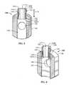
- FIG. 1is an exploded perspective view of a set screw apparatus in accordance with at least one example of the invention.
- FIG. 2is a side view of a set screw in accordance with at least one example of the invention.
- FIG. 3is a cross-sectional view of a block in accordance with at least one example of the invention.
- FIG. 4is a perspective view of a set screw apparatus in accordance with at least one example of the invention.
- FIG. 5is a cross-sectional view of a set screw apparatus in accordance with at least one example of the invention.
- FIG. 6is a cross-sectional perspective view of a set screw apparatus in accordance with at least one example of the invention.
- FIG. 7is a cross-sectional perspective view of a set screw apparatus in accordance with at least one example of the invention and showing motion of a set screw threadably engaged with a block.
- FIG. 8is a cross-sectional perspective view of a set screw apparatus in accordance with at least one example of the invention and showing motion of a set screw not threadably engaged with a block.
- the present patent applicationrelates to a set screw apparatus.
- the set screw apparatusis configured to retain a therapy delivery element (or an extension for a therapy delivery element) with respect to a device.
- the set screw apparatusincludes a set screw that will be retained within a block even if the set screw is backed out completely from the block. In this way, the examples of set screw apparatuses described herein can reduce, if not eliminate, expenditures of time, effort, and/or money due to set screws being completely backed out of and disengaged from the blocks (accidentally or otherwise).
- set screw apparatusesare mostly described herein with respect to retention of a therapy delivery element (or an extension for a therapy delivery element) within a medical device, it should be noted that this is for the sake of convenience and should not be limited as such.
- the present subject mattercan be applied to retention of devices other than therapy delivery elements with respect to medical devices.
- the present subject mattercan be applied to areas other than the medical device area.
- the present subject mattercan be applied to any set screw configuration.
- a set screw apparatus 100is configured to retain a device, such as, but not limited to, a therapy delivery element 10 (or an extension for a therapy delivery element), on, in, or otherwise with respect to another device, such as, but not limited to, a pulse generator.
- the set screw apparatus 100is configured to be implemented in a header or other such assembly of a medical device, the header or other such assembly being configured to accept and/or retain one or more therapy delivery elements 10 (or extensions).
- the set screw apparatus 100includes a set screw 120 and a block 140 configured to accept the set screw 120 .
- the set screw 120includes a set screw body 122 .
- the set screw body 122includes a cylindrical shape.
- the set screw body 122in some examples, includes a distal end 122 A and a proximal end 122 B.
- the proximal end 122 B of the set screw body 122includes a tool engagement opening 121 .
- the tool engagement opening 121include any shape to accommodate a tool for rotating the set screw 120 with respect to the block 140 , such as, but not limited to a hex wrench, a slot head screw driver, a Phillips head screw driver, a hexalobular wrench, or the like.
- the tool engagement opening 121extends a distance into the set screw body 122 . In further examples, the tool engagement opening 121 extends entirely through the set screw body 122 from the proximal end 122 B to the distal end 122 A. In some examples, the set screw body 122 is substantially tubular. In some examples, with the tool engagement opening 121 extending entirely through the set screw body 122 , it allows access to the tool engagement opening 121 from both the distal end 122 A and the proximal end 122 B of the set screw 120 .
- Providing access to the tool engagement opening 121 from the distal end 122 Afacilitates initial insertion and threading of the set screw 120 into the block 140 to assemble the set screw apparatus 100 , which, in some examples, is accomplished by inserting the set screw into the bore 142 from a bottom of the block 140 and rotating the set screw 120 with respect to the block 140 using a corresponding tool within the tool engagement opening 121 at the distal end 122 A of the set screw 120 .
- the tool engagement opening 121extending entirely through the set screw body 122 allows for a larger amount of surface area against which a corresponding tool interacts to rotate the set screw 120 with respect to the block 140 than if the tool engagement opening extended only partially through the set screw.
- the larger amount of surface areacan reduce the possibility of stripping or otherwise damaging the tool engagement opening 121 of the set screw 122 by distributing forces encountered during rotation of the set screw 120 using a corresponding tool over a larger area.
- the set screwcan include separate tool engagement openings at each of the distal end and the proximal end, such that the tool engagement openings are not fluidly coupled with one another. That is, one tool engagement opening extends from the proximal end of the set screw a distance into the set screw, and the other tool engagement opening extends from the distal end of the set screw a distance into the set screw without intersecting the tool engagement opening of the proximal end.
- the tool engagement opening 121can be configured in various ways, provided that the tool engagement opening 121 allows a user to rotate the set screw 120 with respect to the block 140 using a corresponding tool, for instance, to tighten the set screw 120 against a portion of a therapy delivery element 10 (or extension) in order to retain the therapy delivery element 10 (or extension) with a medical device or to loosen the set screw 120 , for instance, to remove the therapy delivery element 10 (or extension) from the medical device.
- the set screw 120includes one or more set screw threads 125 extending radially outwardly from the set screw body 122 and disposed along a threaded set screw area 124 of the set screw body 122 .
- the threaded set screw area 124includes a first length L 1 ( FIG. 2 ) measured longitudinally along the set screw body 122 .
- the threaded set screw area 124is disposed at the proximal end 122 B of the set screw body 122 . In other examples, the threaded set screw area can be disposed at any point along the set screw body 122 .
- the set screw 120includes an abutment 128 extending radially outwardly from the set screw body 122 and longitudinally separated from the threaded set screw area 124 by an unthreaded set screw area 126 of the set screw body 122 .
- the unthreaded set screw area 126includes a second length L 2 ( FIG. 2 ) measured longitudinally along the set screw body 122 .
- the abutment 128is integrally formed with the set screw body 122 .
- the abutment 128is disposed proximate the distal end 122 A of the set screw body 122 .
- the abutment 128in some examples, is substantially annular.
- the abutment 128extends from the set screw body 122 completely around the set screw body 122 . In some examples, the abutment extends partially around the set screw body. In some examples, the abutment is segmented around or partially around the set screw body.
- the block 140includes a bore 142 sized and shaped to accept the set screw 120 within the bore 142 .
- the block 140includes one or more block threads 145 extending radially inwardly from the bore 142 and disposed along a threaded block area 144 of the bore 142 .
- the one or more block threads 145are complementary with the one or more set screw threads 125 so as to be threadably engageable with the one or more set screw threads 125 , such that rotation of the set screw 120 with respect to the block 140 causes the set screw 120 to move longitudinally within the bore 142 along arrow X ( FIG. 5 ).
- rotation of the set screw 120 with respect to the block 140 in a first direction Acauses the set screw 120 to move longitudinally within the bore 142 along arrow Y.
- rotation of the set screw 120 with respect to the block 140 in a second direction Bcauses the set screw 120 to move longitudinally within the bore 142 along arrow Z.
- the first direction Ais opposite the second direction B.
- the direction Ais counterclockwise, and the direction B is clockwise.
- rotation of the set screw 120moves the set screw 120 outwardly (along the arrow Y) or inwardly (along the arrow Z) with respect to the bore 142 , for instance, to release or retain, respectively, a portion of a therapy delivery element 10 ( FIG. 4 ) (or extension) within the block 140 using the set screw 120 .
- the threaded block area 144includes a third length L 3 ( FIG. 3 ) measured longitudinally along the bore 142 .
- the abutment 128is sized and shaped to abut, but not threadably engage with, the one or more block threads 145 . In this way, this configuration inhibits movement of the set screw 120 past the threaded block area 144 and removal of the set screw 120 from the bore 142 .
- the third length L 3is shorter than the second length L 2 so that an entirety of the threaded block area 144 can be disposed within the unthreaded set screw area 126 between the threaded set screw area 124 and the abutment 128 .
- the set screw 120is freely rotatable within the bore 142 , but retained within the bore 142 , if turned in the first direction A with respect to the block 140 .
- the block 140includes a passage 146 fluidly coupled with the bore 142 .
- the passage 146is oriented within the block 140 substantially perpendicularly to the bore 142 .
- the passage 146is configured to selectively accept a proximal end of a therapy delivery element 10 (or extension). With the proximal end of the therapy delivery element 10 (or extension) disposed within the passage 146 , in some examples, rotation of the set screw 120 in the second direction B with respect to the block 140 causes the set screw 120 to move in the inward direction Z with respect to the block 140 to bear against the proximal end of the therapy delivery element 10 .
- one or more passages 146 of one or more blocks 140can be disposed within a header (for instance, of a medical device), the number of blocks 140 and passages 146 corresponding to a number of therapy delivery elements 10 (or extensions) that are to be attached to the header.
- the set screw apparatus 100can be used with an implantable medical device.
- the set screw 120can be used to retain the proximal end of the therapy delivery element 10 (or extension) within the block 140 .
- the set screw 120prior to inserting the proximal end of the therapy delivery element 10 (or extension) into the passage 146 (or in order to remove an already-inserted proximal end of the therapy delivery element 10 or extension from the passage 146 ), the set screw 120 can be rotated in the first direction A to move the set screw 120 in the outward direction Y with respect to the bore 142 and the passage 146 and leave the passage 146 unobstructed by the set screw 120 ( FIG. 5 ).
- a physician or other user rotating the set screw 120need not worry about the set screw 120 releasing, dislodging, or otherwise falling out of the block 140 if the physician or other user rotates the set screw 120 more than is necessary in the first direction A.
- the set screw 120instead of releasing, dislodging, or otherwise falling out of the block 140 , with the threaded block area 144 disposed within the unthreaded set screw area 126 , the set screw 120 will become captive in the block 140 and freely rotate with respect to the block 140 when rotated in the first direction A.
- the abutment 128inhibits the set screw 120 from being removed from within the bore 140 , for instance, if an outward force is applied to the set screw.
- an outward force applied to the set screw 120could result from gravity if the set screw apparatus 100 is held with the set screw 120 facing in a substantially downward direction, from higher pressure within the block 140 than outside the block 140 , from a pulling force applied to the set screw 120 , or the like.
- the proximal end of the therapy delivery element 10 (or extension)can be inserted within (or removed from) the passage 146 .
- the physician or other usercan rotate the set screw 120 in the second direction B to move the set screw 120 in the inward direction Z to allow the set screw 120 to contact and bear against the proximal end of the therapy delivery element 10 (or extension), thereby positively engaging the proximal end of the therapy delivery element 10 (or extension) with the set screw apparatus 100 and retaining or helping to retain the proximal end of the therapy delivery element 10 (or extension) within the header or other device with which the set screw apparatus 100 is being used.
- the set screw apparatusretains the set screw within the block even when the threads of the set screw are completely backed out from the threads of the block. In this way, the possibility of the set screw falling out of the block is reduced, if not eliminated, thereby reducing, if not eliminating, additional costs, time, effort, or health complications associated with the set screw falling out of the block and/or the re-engagement of the set screw with the block or the replacement of the device with which the set screw apparatus is associated. While various advantages of the example apparatuses are listed herein, this list is not considered to be complete, as further advantages may become apparent from the description and figures presented herein.
- the terms “a” or “an”are used to include one or more than one, independent of any other instances or usages of “at least one” or “one or more.”
- the term “or”is used to refer to a nonexclusive or, such that “A or B” includes “A but not B,” “B but not A,” and “A and B,” unless otherwise indicated.
- the terms “about” and “approximately” or similarare used to refer to an amount that is nearly, almost, or in the vicinity of being equal to a stated amount.
Landscapes
- Engineering & Computer Science (AREA)
- General Engineering & Computer Science (AREA)
- Mechanical Engineering (AREA)
- Health & Medical Sciences (AREA)
- Biomedical Technology (AREA)
- Nuclear Medicine, Radiotherapy & Molecular Imaging (AREA)
- Radiology & Medical Imaging (AREA)
- Life Sciences & Earth Sciences (AREA)
- Animal Behavior & Ethology (AREA)
- General Health & Medical Sciences (AREA)
- Public Health (AREA)
- Veterinary Medicine (AREA)
- Surgical Instruments (AREA)
Abstract
Description
Claims (18)
Priority Applications (2)
| Application Number | Priority Date | Filing Date | Title |
|---|---|---|---|
| US14/032,316US9068587B2 (en) | 2013-09-20 | 2013-09-20 | Set screw apparatus |
| US14/735,234US10047782B2 (en) | 2013-09-20 | 2015-06-10 | Set screw apparatus |
Applications Claiming Priority (1)
| Application Number | Priority Date | Filing Date | Title |
|---|---|---|---|
| US14/032,316US9068587B2 (en) | 2013-09-20 | 2013-09-20 | Set screw apparatus |
Related Child Applications (1)
| Application Number | Title | Priority Date | Filing Date |
|---|---|---|---|
| US14/735,234ContinuationUS10047782B2 (en) | 2013-09-20 | 2015-06-10 | Set screw apparatus |
Publications (2)
| Publication Number | Publication Date |
|---|---|
| US20150086292A1 US20150086292A1 (en) | 2015-03-26 |
| US9068587B2true US9068587B2 (en) | 2015-06-30 |
Family
ID=52691081
Family Applications (2)
| Application Number | Title | Priority Date | Filing Date |
|---|---|---|---|
| US14/032,316Active2034-01-03US9068587B2 (en) | 2013-09-20 | 2013-09-20 | Set screw apparatus |
| US14/735,234Active2033-11-26US10047782B2 (en) | 2013-09-20 | 2015-06-10 | Set screw apparatus |
Family Applications After (1)
| Application Number | Title | Priority Date | Filing Date |
|---|---|---|---|
| US14/735,234Active2033-11-26US10047782B2 (en) | 2013-09-20 | 2015-06-10 | Set screw apparatus |
Country Status (1)
| Country | Link |
|---|---|
| US (2) | US9068587B2 (en) |
Cited By (10)
| Publication number | Priority date | Publication date | Assignee | Title |
|---|---|---|---|---|
| US20130231707A1 (en)* | 2012-03-01 | 2013-09-05 | Brad Juchno | Closed-Head Polyaxial and Monaxial Screws |
| US20140012332A1 (en)* | 2004-11-10 | 2014-01-09 | Roger P. Jackson | Polyaxial bone screw with shank articulation pressure insert and method |
| US9717533B2 (en) | 2013-12-12 | 2017-08-01 | Roger P. Jackson | Bone anchor closure pivot-splay control flange form guide and advancement structure |
| US9907577B2 (en) | 2000-12-08 | 2018-03-06 | Roger P. Jackson | Closure for open-headed medical implant |
| USD812460S1 (en) | 2016-08-19 | 2018-03-13 | Katsuyuki Totsu | Screw |
| USD817164S1 (en) | 2016-08-19 | 2018-05-08 | Katsuyuki Totsu | Screw |
| US10299833B2 (en) | 2012-11-21 | 2019-05-28 | Roger P. Jackson | Splay control closure for open bone anchor |
| US10548641B2 (en) | 2012-01-10 | 2020-02-04 | Roger P. Jackson | Medical implant receivers having dual lead in closure mating thread forms |
| US11147591B2 (en) | 2004-11-10 | 2021-10-19 | Roger P Jackson | Pivotal bone anchor receiver assembly with threaded closure |
| US11224464B2 (en) | 2002-05-09 | 2022-01-18 | Roger P. Jackson | Threaded closure with inwardly-facing tool engaging concave radiused structures and axial through-aperture |
Families Citing this family (20)
| Publication number | Priority date | Publication date | Assignee | Title |
|---|---|---|---|---|
| CA2903843C (en) | 2013-03-15 | 2019-03-05 | Alfred E. Mann Foundation For Scientific Research | Current sensing multiple output current stimulators with fast turn on time |
| US9780596B2 (en) | 2013-07-29 | 2017-10-03 | Alfred E. Mann Foundation For Scientific Research | Microprocessor controlled class E driver |
| US9702385B2 (en)* | 2014-05-15 | 2017-07-11 | Iscar, Ltd. | Machine tool assembly configured for swift disassembly |
| AU2015301398B2 (en) | 2014-08-15 | 2020-05-21 | Axonics Modulation Technologies, Inc. | Implantable lead affixation structure for nerve stimulation to alleviate bladder dysfunction and other indications |
| AU2015301401B2 (en) | 2014-08-15 | 2020-01-16 | Axonics Modulation Technologies, Inc. | Electromyographic lead positioning and stimulation titration in a nerve stimulation system for treatment of overactive bladder |
| CA2958210C (en) | 2014-08-15 | 2023-09-26 | Axonics Modulation Technologies, Inc. | Integrated electromyographic clinician programmer for use with an implantable neurostimulator |
| ES2782556T3 (en) | 2014-08-15 | 2020-09-15 | Axonics Modulation Tech Inc | System for neurostimulation electrode configurations based on neuronal location |
| CA3208375A1 (en) | 2014-08-15 | 2016-02-18 | Axonics, Inc. | External pulse generator device and associated methods for trial nerve stimulation |
| CN107427675B (en) | 2015-01-09 | 2021-10-26 | 艾克索尼克斯股份有限公司 | Patient remote control and associated method for use with a neurostimulation system |
| CA2973192C (en) | 2015-01-09 | 2023-04-04 | Axonics Modulation Technologies, Inc. | Improved antenna and methods of use for an implantable nerve stimulator |
| JP6751718B2 (en) | 2015-01-09 | 2020-09-09 | アクソニクス モジュレーション テクノロジーズ インコーポレイテッド | Mounting devices and related methods for use with neurostimulation charging devices |
| AU2016291554B2 (en) | 2015-07-10 | 2021-01-07 | Axonics Modulation Technologies, Inc. | Implantable nerve stimulator having internal electronics without ASIC and methods of use |
| JP6876363B2 (en) | 2016-01-29 | 2021-05-26 | アクソニクス モジュレーション テクノロジーズ インコーポレイテッド | Methods and systems for frequency adjustment that optimize the charging of implantable neurostimulators |
| WO2017139784A1 (en) | 2016-02-12 | 2017-08-17 | Axonics Modulation Technologies, Inc. | External pulse generator device and associated methods for trial nerve stimulation |
| WO2019165108A1 (en) | 2018-02-22 | 2019-08-29 | Axonics Modulation Technologies, Inc. | Neurostimulation leads for trial nerve stimulation and methods of use |
| US11642537B2 (en) | 2019-03-11 | 2023-05-09 | Axonics, Inc. | Charging device with off-center coil |
| US11439829B2 (en) | 2019-05-24 | 2022-09-13 | Axonics, Inc. | Clinician programmer methods and systems for maintaining target operating temperatures |
| WO2020242900A1 (en) | 2019-05-24 | 2020-12-03 | Axonics Modulation Technologies, Inc. | Trainer device for a neurostimulator programmer and associated methods of use with a neurostimulation system |
| US12420103B1 (en) | 2020-08-20 | 2025-09-23 | Axonics, Inc. | Neurostimulation leads with reduced current leakage |
| CN113926080B (en)* | 2021-11-08 | 2025-08-01 | 北京品驰医疗设备股份有限公司 | Electrode protection cap |
Citations (22)
| Publication number | Priority date | Publication date | Assignee | Title |
|---|---|---|---|---|
| US278759A (en)* | 1883-06-05 | Set-screw | ||
| US1187430A (en)* | 1915-01-16 | 1916-06-13 | Leonard C Grove | Hose-clamp. |
| US1487682A (en)* | 1922-07-03 | 1924-03-18 | Trumbull Electric Mfg Co | Electric-circuit terminal |
| US2295314A (en)* | 1940-05-04 | 1942-09-08 | Ernest C Whitney | Setscrew |
| US3260989A (en)* | 1964-08-27 | 1966-07-12 | Curtis Dev & Mfg Co | Captivated screw |
| US3346835A (en) | 1965-07-19 | 1967-10-10 | Buchanan Electrical Prod Corp | Electrical connector |
| US3424212A (en)* | 1967-04-12 | 1969-01-28 | United Co The | Screw wrench device |
| US3426321A (en)* | 1965-10-08 | 1969-02-04 | Hubbell Inc Harvey | Electrical wiring device having improved captured screw terminals |
| US3434103A (en)* | 1967-01-04 | 1969-03-18 | Curtis Dev & Mfg Co | Electrical terminal with captive screw |
| US3737839A (en) | 1970-08-04 | 1973-06-05 | G Marechal | Connector terminal having a contact socket assembly for receiving the end of a conductor |
| US4027940A (en) | 1976-08-10 | 1977-06-07 | Amerace Corporation | Electrical connector with captive clamping jaw |
| US4304424A (en)* | 1979-04-06 | 1981-12-08 | Meyertech Corporation | Rapid installation fitting for plain end pipe |
| US4316471A (en) | 1980-05-19 | 1982-02-23 | Coratomic, Inc. | Organ stimulating apparatus with sealing setscrew |
| US5052643A (en)* | 1990-03-26 | 1991-10-01 | Heyco Molded Products, Inc. | Screw and screw releasable strain relief bushing with a non-fall out screw |
| DE19513281A1 (en) | 1995-04-07 | 1996-10-10 | Kopp Heinrich Ag | Combination terminal-clamp for automatic cut=outs |
| US5580286A (en) | 1994-05-05 | 1996-12-03 | The Whitaker Corporation | Electrical connector/assembly with screw clamp terminals |
| US5713705A (en)* | 1996-03-01 | 1998-02-03 | Gruenbichler; Carl | Fastener bolt with limited torque head |
| US7210968B1 (en) | 2005-01-04 | 2007-05-01 | Pacesetter, Inc. | Dual-locking mechanism for lead and header attachment in pre-molded headers |
| US7308312B1 (en) | 2005-03-03 | 2007-12-11 | Pacesetter, Inc. | Setscrew retention in connector block for implantable medical device |
| US7402076B1 (en) | 2006-10-26 | 2008-07-22 | Pacesetter, Inc. | Retaining mechanism for an implantable medical device connector assembly |
| US8032221B2 (en) | 2009-03-24 | 2011-10-04 | Medtronic, Inc. | Sealing setscrew |
| US8241074B2 (en) | 2009-03-18 | 2012-08-14 | Siemens Industry, Inc. | Circuit breakers with lug screw retention and methods for manufacturing same |
Family Cites Families (9)
| Publication number | Priority date | Publication date | Assignee | Title |
|---|---|---|---|---|
| US1927780A (en)* | 1932-01-09 | 1933-09-19 | Appleton Electric Co | Means to prevent loss of screws |
| US2010853A (en)* | 1934-08-25 | 1935-08-13 | Leonard H Dyer | Shackle |
| US2283974A (en)* | 1940-12-06 | 1942-05-26 | Hanlon Waters Inc | Coupling |
| US3212387A (en)* | 1962-05-08 | 1965-10-19 | California Plasteck Inc | Plastic captive screw washer |
| US3378806A (en)* | 1965-10-23 | 1968-04-16 | Web Press Eng Inc | Electrical connector |
| US3817271A (en)* | 1971-08-15 | 1974-06-18 | L Roven | Refrigeration by-pass and service valve |
| GB8805829D0 (en)* | 1988-03-11 | 1988-04-13 | Eaton Sa | Locking fastener |
| US6276865B1 (en)* | 1998-10-30 | 2001-08-21 | The Torrington Company | Steering column shaft clamp |
| US8573912B2 (en)* | 2011-02-03 | 2013-11-05 | Kennametal Inc. | Fastener for attaching a milling cutter body to an adaptor and method of installing same |
- 2013
- 2013-09-20USUS14/032,316patent/US9068587B2/enactiveActive
- 2015
- 2015-06-10USUS14/735,234patent/US10047782B2/enactiveActive
Patent Citations (22)
| Publication number | Priority date | Publication date | Assignee | Title |
|---|---|---|---|---|
| US278759A (en)* | 1883-06-05 | Set-screw | ||
| US1187430A (en)* | 1915-01-16 | 1916-06-13 | Leonard C Grove | Hose-clamp. |
| US1487682A (en)* | 1922-07-03 | 1924-03-18 | Trumbull Electric Mfg Co | Electric-circuit terminal |
| US2295314A (en)* | 1940-05-04 | 1942-09-08 | Ernest C Whitney | Setscrew |
| US3260989A (en)* | 1964-08-27 | 1966-07-12 | Curtis Dev & Mfg Co | Captivated screw |
| US3346835A (en) | 1965-07-19 | 1967-10-10 | Buchanan Electrical Prod Corp | Electrical connector |
| US3426321A (en)* | 1965-10-08 | 1969-02-04 | Hubbell Inc Harvey | Electrical wiring device having improved captured screw terminals |
| US3434103A (en)* | 1967-01-04 | 1969-03-18 | Curtis Dev & Mfg Co | Electrical terminal with captive screw |
| US3424212A (en)* | 1967-04-12 | 1969-01-28 | United Co The | Screw wrench device |
| US3737839A (en) | 1970-08-04 | 1973-06-05 | G Marechal | Connector terminal having a contact socket assembly for receiving the end of a conductor |
| US4027940A (en) | 1976-08-10 | 1977-06-07 | Amerace Corporation | Electrical connector with captive clamping jaw |
| US4304424A (en)* | 1979-04-06 | 1981-12-08 | Meyertech Corporation | Rapid installation fitting for plain end pipe |
| US4316471A (en) | 1980-05-19 | 1982-02-23 | Coratomic, Inc. | Organ stimulating apparatus with sealing setscrew |
| US5052643A (en)* | 1990-03-26 | 1991-10-01 | Heyco Molded Products, Inc. | Screw and screw releasable strain relief bushing with a non-fall out screw |
| US5580286A (en) | 1994-05-05 | 1996-12-03 | The Whitaker Corporation | Electrical connector/assembly with screw clamp terminals |
| DE19513281A1 (en) | 1995-04-07 | 1996-10-10 | Kopp Heinrich Ag | Combination terminal-clamp for automatic cut=outs |
| US5713705A (en)* | 1996-03-01 | 1998-02-03 | Gruenbichler; Carl | Fastener bolt with limited torque head |
| US7210968B1 (en) | 2005-01-04 | 2007-05-01 | Pacesetter, Inc. | Dual-locking mechanism for lead and header attachment in pre-molded headers |
| US7308312B1 (en) | 2005-03-03 | 2007-12-11 | Pacesetter, Inc. | Setscrew retention in connector block for implantable medical device |
| US7402076B1 (en) | 2006-10-26 | 2008-07-22 | Pacesetter, Inc. | Retaining mechanism for an implantable medical device connector assembly |
| US8241074B2 (en) | 2009-03-18 | 2012-08-14 | Siemens Industry, Inc. | Circuit breakers with lug screw retention and methods for manufacturing same |
| US8032221B2 (en) | 2009-03-24 | 2011-10-04 | Medtronic, Inc. | Sealing setscrew |
Cited By (28)
| Publication number | Priority date | Publication date | Assignee | Title |
|---|---|---|---|---|
| US9907577B2 (en) | 2000-12-08 | 2018-03-06 | Roger P. Jackson | Closure for open-headed medical implant |
| US10993745B2 (en) | 2000-12-08 | 2021-05-04 | Roger P. Jackson | Threaded closure mechanism having a closed body with inwardly-facing concave radiused tool engaging surfaces and a downwardly extending rod-engaging structure |
| US10925647B2 (en) | 2000-12-08 | 2021-02-23 | Roger P. Jackson | Threaded closure with inwardly-facing tool engaging concave radiused structures and axial through-aperture |
| US11224464B2 (en) | 2002-05-09 | 2022-01-18 | Roger P. Jackson | Threaded closure with inwardly-facing tool engaging concave radiused structures and axial through-aperture |
| US10245077B2 (en) | 2004-11-10 | 2019-04-02 | Roger P. Jackson | Bone anchor receiver with horizontal radiused tool attachment grooves and 2-part closure |
| US9743957B2 (en)* | 2004-11-10 | 2017-08-29 | Roger P. Jackson | Polyaxial bone screw with shank articulation pressure insert and method |
| US11564714B2 (en) | 2004-11-10 | 2023-01-31 | Roger P. Jackson | Spinal stabilization implant assemblies with interchangeable threaded closures |
| US11278327B2 (en) | 2004-11-10 | 2022-03-22 | Roger P. Jackson | Pivotal bone anchor receiver assembly with unitary and multi-part interchangeable threaded closures |
| US11147591B2 (en) | 2004-11-10 | 2021-10-19 | Roger P Jackson | Pivotal bone anchor receiver assembly with threaded closure |
| US20140012332A1 (en)* | 2004-11-10 | 2014-01-09 | Roger P. Jackson | Polyaxial bone screw with shank articulation pressure insert and method |
| US10898233B2 (en) | 2012-01-10 | 2021-01-26 | Roger P. Jackson | Medical implant receivers having dual lead in closure mating thread forms and curvate extending instrument engaging grooves |
| US11399873B2 (en) | 2012-01-10 | 2022-08-02 | Roger P. Jackson | Medical implant threaded plug having a start structure |
| US11129646B2 (en) | 2012-01-10 | 2021-09-28 | Roger P. Jackson | Medical implant threaded plug having a start structure with symmetrically shaped concave and convex leading surfaces |
| US10548641B2 (en) | 2012-01-10 | 2020-02-04 | Roger P. Jackson | Medical implant receivers having dual lead in closure mating thread forms |
| US10219839B2 (en)* | 2012-03-01 | 2019-03-05 | Globus Medical, Inc. | Closed-head polyaxial and monaxial screws |
| US11890036B2 (en)* | 2012-03-01 | 2024-02-06 | Globus Medical Inc. | Closed-head polyaxial and monaxial screws |
| US9427260B2 (en)* | 2012-03-01 | 2016-08-30 | Globus Medical, Inc. | Closed-head polyaxial and monaxial screws |
| US20130231707A1 (en)* | 2012-03-01 | 2013-09-05 | Brad Juchno | Closed-Head Polyaxial and Monaxial Screws |
| US20220409242A1 (en)* | 2012-03-01 | 2022-12-29 | Globus Medical, Inc. | Closed-head polyaxial and monaxial screws |
| US20160338739A1 (en)* | 2012-03-01 | 2016-11-24 | Globus Medical, Inc. | Closed-head polyaxial and monaxial screws |
| US11439439B2 (en)* | 2012-03-01 | 2022-09-13 | Globus Medical, Inc. | Closed-head polyaxial and monaxial screws |
| US10299833B2 (en) | 2012-11-21 | 2019-05-28 | Roger P. Jackson | Splay control closure for open bone anchor |
| US10687855B2 (en) | 2012-11-21 | 2020-06-23 | Roger P. Jackson | Bone anchor receiver with extension portions having controlled splay allowance helically wound flange forms |
| US9861394B2 (en) | 2013-12-12 | 2018-01-09 | Roger P. Jackson | Bone anchor closure pivot-splay control flange form guide and advancement structure |
| US10206716B2 (en) | 2013-12-12 | 2019-02-19 | Roger P. Jackson | Bone anchor closure flange form guide and advancement structure with controlled splay |
| US9717533B2 (en) | 2013-12-12 | 2017-08-01 | Roger P. Jackson | Bone anchor closure pivot-splay control flange form guide and advancement structure |
| USD812460S1 (en) | 2016-08-19 | 2018-03-13 | Katsuyuki Totsu | Screw |
| USD817164S1 (en) | 2016-08-19 | 2018-05-08 | Katsuyuki Totsu | Screw |
Also Published As
| Publication number | Publication date |
|---|---|
| US20150086292A1 (en) | 2015-03-26 |
| US20150275954A1 (en) | 2015-10-01 |
| US10047782B2 (en) | 2018-08-14 |
Similar Documents
| Publication | Publication Date | Title |
|---|---|---|
| US9068587B2 (en) | Set screw apparatus | |
| US11358259B2 (en) | Driver tool and method of use | |
| EP3366243B1 (en) | Surgical screw and fusion device using same | |
| EP2616695B1 (en) | Ratchet locking mechanism for threaded fastener | |
| US9841046B2 (en) | Locking fastener with deflectable lock | |
| US20080147128A1 (en) | Cannulated bone screw and cannulated driver for the implantation thereof | |
| WO2015175376A4 (en) | Sacral fixation system | |
| US20160143676A1 (en) | Variable Angle Bone Fixation Device | |
| JP2016529998A5 (en) | ||
| US9044843B1 (en) | Strip resistant screw and rescue driver | |
| AU2018253614A1 (en) | Polyaxial locking mechanism | |
| WO2014158745A3 (en) | Applicator systems for surgical fasteners | |
| US8747040B2 (en) | Screw assembly element | |
| BR112018002931B1 (en) | fixation system | |
| WO2008130855A3 (en) | Threaded screw fastener with multiple characteristic threads | |
| RU2017128050A (en) | VALVE STEM AND PLUG CONNECTIONS AND CRIMPING TOOLS | |
| US20150134009A1 (en) | Locking mechanism for pectus bar | |
| US20150104268A1 (en) | Lockable single nut assembly | |
| KR20180050296A (en) | Surgical assembly for positioning a pedicle screw cap | |
| BR112013027097B1 (en) | bolt without nut | |
| US20140109381A1 (en) | Fastener retention system | |
| CA3014276C (en) | Key wrench | |
| JP2012533033A5 (en) | ||
| RU2737098C2 (en) | Fastening system and method of attachment | |
| JP2018004067A (en) | Falling-off prevention device for fastening nut |
Legal Events
| Date | Code | Title | Description |
|---|---|---|---|
| AS | Assignment | Owner name:GREATBATCH LTD., NEW YORK Free format text:ASSIGNMENT OF ASSIGNORS INTEREST;ASSIGNORS:SAGE, SHAHN S.;WALCH, TOM;RICHARDSON, ANDREW;AND OTHERS;REEL/FRAME:031247/0245 Effective date:20130919 | |
| STCF | Information on status: patent grant | Free format text:PATENTED CASE | |
| AS | Assignment | Owner name:MANUFACTURERS AND TRADERS TRUST COMPANY, NEW YORK Free format text:SECURITY INTEREST;ASSIGNORS:GREATBATCH, INC.;GREATBATCH LTD.;ELECTROCHEM SOLUTIONS, INC.;AND OTHERS;REEL/FRAME:036980/0482 Effective date:20151027 | |
| CC | Certificate of correction | ||
| AS | Assignment | Owner name:QIG GROUP, LLC, NEW YORK Free format text:ASSIGNMENT OF ASSIGNORS INTEREST;ASSIGNOR:GREATBATCH LTD.;REEL/FRAME:037810/0051 Effective date:20160212 | |
| AS | Assignment | Owner name:NUVECTRA CORPORATION, TEXAS Free format text:CHANGE OF NAME;ASSIGNOR:QIG GROUP, LLC;REEL/FRAME:038455/0153 Effective date:20160314 | |
| AS | Assignment | Owner name:ELECTROCHEM SOLUTIONS, INC., NEW YORK Free format text:RELEASE BY SECURED PARTY;ASSIGNOR:MANUFACTURERS AND TRADERS TRUST COMPANY;REEL/FRAME:039132/0773 Effective date:20160418 Owner name:GREATBATCH LTD., NEW YORK Free format text:RELEASE BY SECURED PARTY;ASSIGNOR:MANUFACTURERS AND TRADERS TRUST COMPANY;REEL/FRAME:039132/0773 Effective date:20160418 Owner name:GREATBATCH INC., NEW YORK Free format text:RELEASE BY SECURED PARTY;ASSIGNOR:MANUFACTURERS AND TRADERS TRUST COMPANY;REEL/FRAME:039132/0773 Effective date:20160418 Owner name:QIG GROUP LLC, TEXAS Free format text:RELEASE BY SECURED PARTY;ASSIGNOR:MANUFACTURERS AND TRADERS TRUST COMPANY;REEL/FRAME:039132/0773 Effective date:20160418 Owner name:MICRO POWER ELECTRONICS, INC., OREGON Free format text:RELEASE BY SECURED PARTY;ASSIGNOR:MANUFACTURERS AND TRADERS TRUST COMPANY;REEL/FRAME:039132/0773 Effective date:20160418 Owner name:NEURONEXUS TECHNOLOGIES, INC., MICHIGAN Free format text:RELEASE BY SECURED PARTY;ASSIGNOR:MANUFACTURERS AND TRADERS TRUST COMPANY;REEL/FRAME:039132/0773 Effective date:20160418 | |
| MAFP | Maintenance fee payment | Free format text:PAYMENT OF MAINTENANCE FEE, 4TH YEAR, LARGE ENTITY (ORIGINAL EVENT CODE: M1551) Year of fee payment:4 | |
| AS | Assignment | Owner name:CIRTEC MEDICAL CORP., MINNESOTA Free format text:ASSIGNMENT OF ASSIGNORS INTEREST;ASSIGNOR:NUVECTRA CORPORATION;REEL/FRAME:052185/0680 Effective date:20200317 | |
| AS | Assignment | Owner name:MICRO POWER ELECTRONICS, INC., NEW YORK Free format text:RELEASE BY SECURED PARTY;ASSIGNOR:MANUFACTURERS AND TRADERS TRUST COMPANY (AS ADMINISTRATIVE AGENT);REEL/FRAME:060938/0069 Effective date:20210903 Owner name:PRECIMED INC., NEW YORK Free format text:RELEASE BY SECURED PARTY;ASSIGNOR:MANUFACTURERS AND TRADERS TRUST COMPANY (AS ADMINISTRATIVE AGENT);REEL/FRAME:060938/0069 Effective date:20210903 Owner name:GREATBATCH-GLOBE TOOL, INC., NEW YORK Free format text:RELEASE BY SECURED PARTY;ASSIGNOR:MANUFACTURERS AND TRADERS TRUST COMPANY (AS ADMINISTRATIVE AGENT);REEL/FRAME:060938/0069 Effective date:20210903 Owner name:NEURONEXUS TECHNOLOGIES, INC., NEW YORK Free format text:RELEASE BY SECURED PARTY;ASSIGNOR:MANUFACTURERS AND TRADERS TRUST COMPANY (AS ADMINISTRATIVE AGENT);REEL/FRAME:060938/0069 Effective date:20210903 Owner name:ELECTROCHEM SOLUTIONS, INC., NEW YORK Free format text:RELEASE BY SECURED PARTY;ASSIGNOR:MANUFACTURERS AND TRADERS TRUST COMPANY (AS ADMINISTRATIVE AGENT);REEL/FRAME:060938/0069 Effective date:20210903 Owner name:GREATBATCH LTD., NEW YORK Free format text:RELEASE BY SECURED PARTY;ASSIGNOR:MANUFACTURERS AND TRADERS TRUST COMPANY (AS ADMINISTRATIVE AGENT);REEL/FRAME:060938/0069 Effective date:20210903 Owner name:GREATBATCH, INC., NEW YORK Free format text:RELEASE BY SECURED PARTY;ASSIGNOR:MANUFACTURERS AND TRADERS TRUST COMPANY (AS ADMINISTRATIVE AGENT);REEL/FRAME:060938/0069 Effective date:20210903 | |
| AS | Assignment | Owner name:MICRO POWER ELECTRONICS, INC., NEW YORK Free format text:RELEASE BY SECURED PARTY;ASSIGNOR:MANUFACTURERS AND TRADERS TRUST COMPANY (AS ADMINISTRATIVE AGENT);REEL/FRAME:061659/0858 Effective date:20210903 Owner name:PRECIMED INC., NEW YORK Free format text:RELEASE BY SECURED PARTY;ASSIGNOR:MANUFACTURERS AND TRADERS TRUST COMPANY (AS ADMINISTRATIVE AGENT);REEL/FRAME:061659/0858 Effective date:20210903 Owner name:GREATBATCH-GLOBE TOOL, INC., NEW YORK Free format text:RELEASE BY SECURED PARTY;ASSIGNOR:MANUFACTURERS AND TRADERS TRUST COMPANY (AS ADMINISTRATIVE AGENT);REEL/FRAME:061659/0858 Effective date:20210903 Owner name:NEURONEXUS TECHNOLOGIES, INC., NEW YORK Free format text:RELEASE BY SECURED PARTY;ASSIGNOR:MANUFACTURERS AND TRADERS TRUST COMPANY (AS ADMINISTRATIVE AGENT);REEL/FRAME:061659/0858 Effective date:20210903 Owner name:ELECTROCHEM SOLUTIONS, INC., NEW YORK Free format text:RELEASE BY SECURED PARTY;ASSIGNOR:MANUFACTURERS AND TRADERS TRUST COMPANY (AS ADMINISTRATIVE AGENT);REEL/FRAME:061659/0858 Effective date:20210903 Owner name:GREATBATCH LTD., NEW YORK Free format text:RELEASE BY SECURED PARTY;ASSIGNOR:MANUFACTURERS AND TRADERS TRUST COMPANY (AS ADMINISTRATIVE AGENT);REEL/FRAME:061659/0858 Effective date:20210903 Owner name:GREATBATCH, INC., NEW YORK Free format text:RELEASE BY SECURED PARTY;ASSIGNOR:MANUFACTURERS AND TRADERS TRUST COMPANY (AS ADMINISTRATIVE AGENT);REEL/FRAME:061659/0858 Effective date:20210903 | |
| MAFP | Maintenance fee payment | Free format text:PAYMENT OF MAINTENANCE FEE, 8TH YEAR, LARGE ENTITY (ORIGINAL EVENT CODE: M1552); ENTITY STATUS OF PATENT OWNER: LARGE ENTITY Year of fee payment:8 | |
| AS | Assignment | Owner name:BMO HARRIS BANK N.A., AS COLLATERAL AGENT, ILLINOIS Free format text:PATENT SECURITY AGREEMENT;ASSIGNOR:CIRTEC MEDICAL CORP.;REEL/FRAME:062559/0098 Effective date:20230130 |