US9067362B2 - Method of using ultrasonic vibration to secure body tissue with fastening element - Google Patents
Method of using ultrasonic vibration to secure body tissue with fastening elementDownload PDFInfo
- Publication number
- US9067362B2 US9067362B2US11/932,051US93205107AUS9067362B2US 9067362 B2US9067362 B2US 9067362B2US 93205107 AUS93205107 AUS 93205107AUS 9067362 B2US9067362 B2US 9067362B2
- Authority
- US
- United States
- Prior art keywords
- suture
- suture retainer
- retainer
- sections
- fastener
- Prior art date
- Legal status (The legal status is an assumption and is not a legal conclusion. Google has not performed a legal analysis and makes no representation as to the accuracy of the status listed.)
- Expired - Fee Related, expires
Links
- 238000000034methodMethods0.000titleclaimsdescription24
- 239000000463materialSubstances0.000claimsdescription248
- 230000007704transitionEffects0.000claimsdescription67
- 230000005540biological transmissionEffects0.000claimsdescription23
- 229920001169thermoplasticPolymers0.000claimsdescription9
- 239000004416thermosoftening plasticSubstances0.000claimsdescription9
- 238000003825pressingMethods0.000claimsdescription8
- 239000012815thermoplastic materialSubstances0.000claimsdescription7
- 210000003041ligamentAnatomy0.000claimsdescription5
- 210000002435tendonAnatomy0.000claimsdescription5
- 230000000694effectsEffects0.000abstractdescription12
- 210000001519tissueAnatomy0.000description305
- 238000010438heat treatmentMethods0.000description31
- 238000010276constructionMethods0.000description21
- 239000000126substanceSubstances0.000description12
- 229920002988biodegradable polymerPolymers0.000description11
- 239000004621biodegradable polymerSubstances0.000description10
- 210000000988bone and boneAnatomy0.000description9
- 239000007788liquidSubstances0.000description9
- 230000033001locomotionEffects0.000description8
- 210000004872soft tissueAnatomy0.000description8
- 229920006125amorphous polymerPolymers0.000description7
- 239000005014poly(hydroxyalkanoate)Substances0.000description6
- 229920000903polyhydroxyalkanoatePolymers0.000description5
- 239000012141concentrateSubstances0.000description4
- 230000035876healingEffects0.000description4
- 210000004204blood vesselAnatomy0.000description3
- 229920003023plasticPolymers0.000description3
- 239000004033plasticSubstances0.000description3
- 229920004937Dexon®Polymers0.000description2
- AEMRFAOFKBGASW-UHFFFAOYSA-NGlycolic acidPolymersOCC(O)=OAEMRFAOFKBGASW-UHFFFAOYSA-N0.000description2
- 239000004677NylonSubstances0.000description2
- 229920000954PolyglycolidePolymers0.000description2
- 229920001222biopolymerPolymers0.000description2
- 229920001577copolymerPolymers0.000description2
- 210000000936intestineAnatomy0.000description2
- 239000000203mixtureSubstances0.000description2
- 229920001778nylonPolymers0.000description2
- 230000037390scarringEffects0.000description2
- RKDVKSZUMVYZHH-UHFFFAOYSA-N1,4-dioxane-2,5-dioneChemical compoundO=C1COC(=O)CO1RKDVKSZUMVYZHH-UHFFFAOYSA-N0.000description1
- LCSKNASZPVZHEG-UHFFFAOYSA-N3,6-dimethyl-1,4-dioxane-2,5-dione;1,4-dioxane-2,5-dioneChemical groupO=C1COC(=O)CO1.CC1OC(=O)C(C)OC1=OLCSKNASZPVZHEG-UHFFFAOYSA-N0.000description1
- 229920004943Delrin®Polymers0.000description1
- DGAQECJNVWCQMB-PUAWFVPOSA-MIlexoside XXIXChemical compoundC[C@@H]1CC[C@@]2(CC[C@@]3(C(=CC[C@H]4[C@]3(CC[C@@H]5[C@@]4(CC[C@@H](C5(C)C)OS(=O)(=O)[O-])C)C)[C@@H]2[C@]1(C)O)C)C(=O)O[C@H]6[C@@H]([C@H]([C@@H]([C@H](O6)CO)O)O)O.[Na+]DGAQECJNVWCQMB-PUAWFVPOSA-M0.000description1
- 229920003171Poly (ethylene oxide)Polymers0.000description1
- 125000000218acetic acid groupChemical groupC(C)(=O)*0.000description1
- 229920013641bioerodible polymerPolymers0.000description1
- 239000008280bloodSubstances0.000description1
- 210000004369bloodAnatomy0.000description1
- 230000006835compressionEffects0.000description1
- 238000007906compressionMethods0.000description1
- 239000004020conductorSubstances0.000description1
- 239000002178crystalline materialSubstances0.000description1
- 230000001627detrimental effectEffects0.000description1
- 230000000968intestinal effectEffects0.000description1
- 239000000155meltSubstances0.000description1
- 229910052751metalInorganic materials0.000description1
- 239000002184metalSubstances0.000description1
- -1polybutylene terephthalatePolymers0.000description1
- 229920001707polybutylene terephthalatePolymers0.000description1
- 229920000642polymerPolymers0.000description1
- 230000001681protective effectEffects0.000description1
- 239000011347resinSubstances0.000description1
- 229920005989resinPolymers0.000description1
- 230000000717retained effectEffects0.000description1
- 229910052708sodiumInorganic materials0.000description1
- 239000011734sodiumSubstances0.000description1
- 239000007787solidSubstances0.000description1
- 210000002784stomachAnatomy0.000description1
- BDHFUVZGWQCTTF-UHFFFAOYSA-MsulfonateChemical compound[O-]S(=O)=OBDHFUVZGWQCTTF-UHFFFAOYSA-M0.000description1
- 230000003319supportive effectEffects0.000description1
- 229920002994synthetic fiberPolymers0.000description1
- KKEYFWRCBNTPAC-UHFFFAOYSA-Lterephthalate(2-)Chemical compound[O-]C(=O)C1=CC=C(C([O-])=O)C=C1KKEYFWRCBNTPAC-UHFFFAOYSA-L0.000description1
- 229920001187thermosetting polymerPolymers0.000description1
- 239000011345viscous materialSubstances0.000description1
Images


Classifications
- B—PERFORMING OPERATIONS; TRANSPORTING
- B29—WORKING OF PLASTICS; WORKING OF SUBSTANCES IN A PLASTIC STATE IN GENERAL
- B29C—SHAPING OR JOINING OF PLASTICS; SHAPING OF MATERIAL IN A PLASTIC STATE, NOT OTHERWISE PROVIDED FOR; AFTER-TREATMENT OF THE SHAPED PRODUCTS, e.g. REPAIRING
- B29C65/00—Joining or sealing of preformed parts, e.g. welding of plastics materials; Apparatus therefor
- B29C65/02—Joining or sealing of preformed parts, e.g. welding of plastics materials; Apparatus therefor by heating, with or without pressure
- B29C65/08—Joining or sealing of preformed parts, e.g. welding of plastics materials; Apparatus therefor by heating, with or without pressure using ultrasonic vibrations
- A—HUMAN NECESSITIES
- A61—MEDICAL OR VETERINARY SCIENCE; HYGIENE
- A61B—DIAGNOSIS; SURGERY; IDENTIFICATION
- A61B17/00—Surgical instruments, devices or methods
- A61B17/04—Surgical instruments, devices or methods for suturing wounds; Holders or packages for needles or suture materials
- A61B17/0487—Suture clamps, clips or locks, e.g. for replacing suture knots; Instruments for applying or removing suture clamps, clips or locks
- B—PERFORMING OPERATIONS; TRANSPORTING
- B29—WORKING OF PLASTICS; WORKING OF SUBSTANCES IN A PLASTIC STATE IN GENERAL
- B29C—SHAPING OR JOINING OF PLASTICS; SHAPING OF MATERIAL IN A PLASTIC STATE, NOT OTHERWISE PROVIDED FOR; AFTER-TREATMENT OF THE SHAPED PRODUCTS, e.g. REPAIRING
- B29C65/00—Joining or sealing of preformed parts, e.g. welding of plastics materials; Apparatus therefor
- B29C65/48—Joining or sealing of preformed parts, e.g. welding of plastics materials; Apparatus therefor using adhesives, i.e. using supplementary joining material; solvent bonding
- B29C65/50—Joining or sealing of preformed parts, e.g. welding of plastics materials; Apparatus therefor using adhesives, i.e. using supplementary joining material; solvent bonding using adhesive tape, e.g. thermoplastic tape; using threads or the like
- B29C65/5064—Joining or sealing of preformed parts, e.g. welding of plastics materials; Apparatus therefor using adhesives, i.e. using supplementary joining material; solvent bonding using adhesive tape, e.g. thermoplastic tape; using threads or the like of particular form, e.g. being C-shaped, T-shaped
- B29C65/5071—Joining or sealing of preformed parts, e.g. welding of plastics materials; Apparatus therefor using adhesives, i.e. using supplementary joining material; solvent bonding using adhesive tape, e.g. thermoplastic tape; using threads or the like of particular form, e.g. being C-shaped, T-shaped and being composed by one single element
- B—PERFORMING OPERATIONS; TRANSPORTING
- B29—WORKING OF PLASTICS; WORKING OF SUBSTANCES IN A PLASTIC STATE IN GENERAL
- B29C—SHAPING OR JOINING OF PLASTICS; SHAPING OF MATERIAL IN A PLASTIC STATE, NOT OTHERWISE PROVIDED FOR; AFTER-TREATMENT OF THE SHAPED PRODUCTS, e.g. REPAIRING
- B29C65/00—Joining or sealing of preformed parts, e.g. welding of plastics materials; Apparatus therefor
- B29C65/48—Joining or sealing of preformed parts, e.g. welding of plastics materials; Apparatus therefor using adhesives, i.e. using supplementary joining material; solvent bonding
- B29C65/50—Joining or sealing of preformed parts, e.g. welding of plastics materials; Apparatus therefor using adhesives, i.e. using supplementary joining material; solvent bonding using adhesive tape, e.g. thermoplastic tape; using threads or the like
- B29C65/5064—Joining or sealing of preformed parts, e.g. welding of plastics materials; Apparatus therefor using adhesives, i.e. using supplementary joining material; solvent bonding using adhesive tape, e.g. thermoplastic tape; using threads or the like of particular form, e.g. being C-shaped, T-shaped
- B29C65/5085—Joining or sealing of preformed parts, e.g. welding of plastics materials; Apparatus therefor using adhesives, i.e. using supplementary joining material; solvent bonding using adhesive tape, e.g. thermoplastic tape; using threads or the like of particular form, e.g. being C-shaped, T-shaped and comprising grooves, e.g. being E-shaped, H-shaped
- B—PERFORMING OPERATIONS; TRANSPORTING
- B29—WORKING OF PLASTICS; WORKING OF SUBSTANCES IN A PLASTIC STATE IN GENERAL
- B29C—SHAPING OR JOINING OF PLASTICS; SHAPING OF MATERIAL IN A PLASTIC STATE, NOT OTHERWISE PROVIDED FOR; AFTER-TREATMENT OF THE SHAPED PRODUCTS, e.g. REPAIRING
- B29C66/00—General aspects of processes or apparatus for joining preformed parts
- B29C66/01—General aspects dealing with the joint area or with the area to be joined
- B29C66/05—Particular design of joint configurations
- B29C66/10—Particular design of joint configurations particular design of the joint cross-sections
- B29C66/11—Joint cross-sections comprising a single joint-segment, i.e. one of the parts to be joined comprising a single joint-segment in the joint cross-section
- B29C66/112—Single lapped joints
- B29C66/1122—Single lap to lap joints, i.e. overlap joints
- B—PERFORMING OPERATIONS; TRANSPORTING
- B29—WORKING OF PLASTICS; WORKING OF SUBSTANCES IN A PLASTIC STATE IN GENERAL
- B29C—SHAPING OR JOINING OF PLASTICS; SHAPING OF MATERIAL IN A PLASTIC STATE, NOT OTHERWISE PROVIDED FOR; AFTER-TREATMENT OF THE SHAPED PRODUCTS, e.g. REPAIRING
- B29C66/00—General aspects of processes or apparatus for joining preformed parts
- B29C66/50—General aspects of joining tubular articles; General aspects of joining long products, i.e. bars or profiled elements; General aspects of joining single elements to tubular articles, hollow articles or bars; General aspects of joining several hollow-preforms to form hollow or tubular articles
- B29C66/51—Joining tubular articles, profiled elements or bars; Joining single elements to tubular articles, hollow articles or bars; Joining several hollow-preforms to form hollow or tubular articles
- B29C66/52—Joining tubular articles, bars or profiled elements
- B29C66/526—Joining bars
- B—PERFORMING OPERATIONS; TRANSPORTING
- B29—WORKING OF PLASTICS; WORKING OF SUBSTANCES IN A PLASTIC STATE IN GENERAL
- B29C—SHAPING OR JOINING OF PLASTICS; SHAPING OF MATERIAL IN A PLASTIC STATE, NOT OTHERWISE PROVIDED FOR; AFTER-TREATMENT OF THE SHAPED PRODUCTS, e.g. REPAIRING
- B29C66/00—General aspects of processes or apparatus for joining preformed parts
- B29C66/69—General aspects of joining filaments
- B—PERFORMING OPERATIONS; TRANSPORTING
- B29—WORKING OF PLASTICS; WORKING OF SUBSTANCES IN A PLASTIC STATE IN GENERAL
- B29C—SHAPING OR JOINING OF PLASTICS; SHAPING OF MATERIAL IN A PLASTIC STATE, NOT OTHERWISE PROVIDED FOR; AFTER-TREATMENT OF THE SHAPED PRODUCTS, e.g. REPAIRING
- B29C66/00—General aspects of processes or apparatus for joining preformed parts
- B29C66/80—General aspects of machine operations or constructions and parts thereof
- B29C66/81—General aspects of the pressing elements, i.e. the elements applying pressure on the parts to be joined in the area to be joined, e.g. the welding jaws or clamps
- B29C66/814—General aspects of the pressing elements, i.e. the elements applying pressure on the parts to be joined in the area to be joined, e.g. the welding jaws or clamps characterised by the design of the pressing elements, e.g. of the welding jaws or clamps
- B29C66/8141—General aspects of the pressing elements, i.e. the elements applying pressure on the parts to be joined in the area to be joined, e.g. the welding jaws or clamps characterised by the design of the pressing elements, e.g. of the welding jaws or clamps characterised by the surface geometry of the part of the pressing elements, e.g. welding jaws or clamps, coming into contact with the parts to be joined
- B29C66/81411—General aspects of the pressing elements, i.e. the elements applying pressure on the parts to be joined in the area to be joined, e.g. the welding jaws or clamps characterised by the design of the pressing elements, e.g. of the welding jaws or clamps characterised by the surface geometry of the part of the pressing elements, e.g. welding jaws or clamps, coming into contact with the parts to be joined characterised by its cross-section, e.g. transversal or longitudinal, being non-flat
- B29C66/81421—General aspects of the pressing elements, i.e. the elements applying pressure on the parts to be joined in the area to be joined, e.g. the welding jaws or clamps characterised by the design of the pressing elements, e.g. of the welding jaws or clamps characterised by the surface geometry of the part of the pressing elements, e.g. welding jaws or clamps, coming into contact with the parts to be joined characterised by its cross-section, e.g. transversal or longitudinal, being non-flat being convex or concave
- B29C66/81423—General aspects of the pressing elements, i.e. the elements applying pressure on the parts to be joined in the area to be joined, e.g. the welding jaws or clamps characterised by the design of the pressing elements, e.g. of the welding jaws or clamps characterised by the surface geometry of the part of the pressing elements, e.g. welding jaws or clamps, coming into contact with the parts to be joined characterised by its cross-section, e.g. transversal or longitudinal, being non-flat being convex or concave being concave
- B—PERFORMING OPERATIONS; TRANSPORTING
- B29—WORKING OF PLASTICS; WORKING OF SUBSTANCES IN A PLASTIC STATE IN GENERAL
- B29C—SHAPING OR JOINING OF PLASTICS; SHAPING OF MATERIAL IN A PLASTIC STATE, NOT OTHERWISE PROVIDED FOR; AFTER-TREATMENT OF THE SHAPED PRODUCTS, e.g. REPAIRING
- B29C66/00—General aspects of processes or apparatus for joining preformed parts
- B29C66/80—General aspects of machine operations or constructions and parts thereof
- B29C66/83—General aspects of machine operations or constructions and parts thereof characterised by the movement of the joining or pressing tools
- B29C66/832—Reciprocating joining or pressing tools
- B29C66/8322—Joining or pressing tools reciprocating along one axis
- B29C66/83221—Joining or pressing tools reciprocating along one axis cooperating reciprocating tools, each tool reciprocating along one axis
- B—PERFORMING OPERATIONS; TRANSPORTING
- B29—WORKING OF PLASTICS; WORKING OF SUBSTANCES IN A PLASTIC STATE IN GENERAL
- B29C—SHAPING OR JOINING OF PLASTICS; SHAPING OF MATERIAL IN A PLASTIC STATE, NOT OTHERWISE PROVIDED FOR; AFTER-TREATMENT OF THE SHAPED PRODUCTS, e.g. REPAIRING
- B29C66/00—General aspects of processes or apparatus for joining preformed parts
- B29C66/80—General aspects of machine operations or constructions and parts thereof
- B29C66/83—General aspects of machine operations or constructions and parts thereof characterised by the movement of the joining or pressing tools
- B29C66/832—Reciprocating joining or pressing tools
- B29C66/8324—Joining or pressing tools pivoting around one axis
- B29C66/83241—Joining or pressing tools pivoting around one axis cooperating pivoting tools
- B—PERFORMING OPERATIONS; TRANSPORTING
- B29—WORKING OF PLASTICS; WORKING OF SUBSTANCES IN A PLASTIC STATE IN GENERAL
- B29C—SHAPING OR JOINING OF PLASTICS; SHAPING OF MATERIAL IN A PLASTIC STATE, NOT OTHERWISE PROVIDED FOR; AFTER-TREATMENT OF THE SHAPED PRODUCTS, e.g. REPAIRING
- B29C66/00—General aspects of processes or apparatus for joining preformed parts
- B29C66/80—General aspects of machine operations or constructions and parts thereof
- B29C66/84—Specific machine types or machines suitable for specific applications
- B29C66/861—Hand-held tools
- B29C66/8614—Tongs, pincers or scissors
- A—HUMAN NECESSITIES
- A61—MEDICAL OR VETERINARY SCIENCE; HYGIENE
- A61B—DIAGNOSIS; SURGERY; IDENTIFICATION
- A61B17/00—Surgical instruments, devices or methods
- A61B17/04—Surgical instruments, devices or methods for suturing wounds; Holders or packages for needles or suture materials
- A61B17/0401—Suture anchors, buttons or pledgets, i.e. means for attaching sutures to bone, cartilage or soft tissue; Instruments for applying or removing suture anchors
- A61B2017/0445—Suture anchors, buttons or pledgets, i.e. means for attaching sutures to bone, cartilage or soft tissue; Instruments for applying or removing suture anchors cannulated, e.g. with a longitudinal through-hole for passage of an instrument
- A—HUMAN NECESSITIES
- A61—MEDICAL OR VETERINARY SCIENCE; HYGIENE
- A61B—DIAGNOSIS; SURGERY; IDENTIFICATION
- A61B17/00—Surgical instruments, devices or methods
- A61B17/04—Surgical instruments, devices or methods for suturing wounds; Holders or packages for needles or suture materials
- A61B17/0401—Suture anchors, buttons or pledgets, i.e. means for attaching sutures to bone, cartilage or soft tissue; Instruments for applying or removing suture anchors
- A61B2017/0446—Means for attaching and blocking the suture in the suture anchor
- A61B2017/0454—Means for attaching and blocking the suture in the suture anchor the anchor being crimped or clamped on the suture
- A—HUMAN NECESSITIES
- A61—MEDICAL OR VETERINARY SCIENCE; HYGIENE
- A61B—DIAGNOSIS; SURGERY; IDENTIFICATION
- A61B17/00—Surgical instruments, devices or methods
- A61B17/04—Surgical instruments, devices or methods for suturing wounds; Holders or packages for needles or suture materials
- A61B17/0401—Suture anchors, buttons or pledgets, i.e. means for attaching sutures to bone, cartilage or soft tissue; Instruments for applying or removing suture anchors
- A61B2017/0446—Means for attaching and blocking the suture in the suture anchor
- A61B2017/0458—Longitudinal through hole, e.g. suture blocked by a distal suture knot
- A—HUMAN NECESSITIES
- A61—MEDICAL OR VETERINARY SCIENCE; HYGIENE
- A61B—DIAGNOSIS; SURGERY; IDENTIFICATION
- A61B17/00—Surgical instruments, devices or methods
- A61B17/04—Surgical instruments, devices or methods for suturing wounds; Holders or packages for needles or suture materials
- A61B17/0401—Suture anchors, buttons or pledgets, i.e. means for attaching sutures to bone, cartilage or soft tissue; Instruments for applying or removing suture anchors
- A61B2017/0464—Suture anchors, buttons or pledgets, i.e. means for attaching sutures to bone, cartilage or soft tissue; Instruments for applying or removing suture anchors for soft tissue
- A—HUMAN NECESSITIES
- A61—MEDICAL OR VETERINARY SCIENCE; HYGIENE
- A61B—DIAGNOSIS; SURGERY; IDENTIFICATION
- A61B17/00—Surgical instruments, devices or methods
- A61B17/04—Surgical instruments, devices or methods for suturing wounds; Holders or packages for needles or suture materials
- A61B17/0487—Suture clamps, clips or locks, e.g. for replacing suture knots; Instruments for applying or removing suture clamps, clips or locks
- A61B2017/0488—Instruments for applying suture clamps, clips or locks
- A—HUMAN NECESSITIES
- A61—MEDICAL OR VETERINARY SCIENCE; HYGIENE
- A61B—DIAGNOSIS; SURGERY; IDENTIFICATION
- A61B17/00—Surgical instruments, devices or methods
- A61B17/04—Surgical instruments, devices or methods for suturing wounds; Holders or packages for needles or suture materials
- A61B17/06—Needles ; Sutures; Needle-suture combinations; Holders or packages for needles or suture materials
- A61B17/06166—Sutures
- A61B2017/0619—Sutures thermoplastic, e.g. for bonding, welding, fusing or cutting the suture by melting it
- B—PERFORMING OPERATIONS; TRANSPORTING
- B29—WORKING OF PLASTICS; WORKING OF SUBSTANCES IN A PLASTIC STATE IN GENERAL
- B29C—SHAPING OR JOINING OF PLASTICS; SHAPING OF MATERIAL IN A PLASTIC STATE, NOT OTHERWISE PROVIDED FOR; AFTER-TREATMENT OF THE SHAPED PRODUCTS, e.g. REPAIRING
- B29C65/00—Joining or sealing of preformed parts, e.g. welding of plastics materials; Apparatus therefor
- B29C65/48—Joining or sealing of preformed parts, e.g. welding of plastics materials; Apparatus therefor using adhesives, i.e. using supplementary joining material; solvent bonding
- B29C65/4805—Joining or sealing of preformed parts, e.g. welding of plastics materials; Apparatus therefor using adhesives, i.e. using supplementary joining material; solvent bonding characterised by the type of adhesives
- B29C65/481—Non-reactive adhesives, e.g. physically hardening adhesives
- B29C65/4815—Hot melt adhesives, e.g. thermoplastic adhesives
- B—PERFORMING OPERATIONS; TRANSPORTING
- B29—WORKING OF PLASTICS; WORKING OF SUBSTANCES IN A PLASTIC STATE IN GENERAL
- B29C—SHAPING OR JOINING OF PLASTICS; SHAPING OF MATERIAL IN A PLASTIC STATE, NOT OTHERWISE PROVIDED FOR; AFTER-TREATMENT OF THE SHAPED PRODUCTS, e.g. REPAIRING
- B29C66/00—General aspects of processes or apparatus for joining preformed parts
- B29C66/50—General aspects of joining tubular articles; General aspects of joining long products, i.e. bars or profiled elements; General aspects of joining single elements to tubular articles, hollow articles or bars; General aspects of joining several hollow-preforms to form hollow or tubular articles
- B29C66/51—Joining tubular articles, profiled elements or bars; Joining single elements to tubular articles, hollow articles or bars; Joining several hollow-preforms to form hollow or tubular articles
- B29C66/52—Joining tubular articles, bars or profiled elements
- B29C66/526—Joining bars
- B29C66/5261—Joining bars for forming coaxial connections, i.e. the bars to be joined forming a zero angle relative to each other
- B—PERFORMING OPERATIONS; TRANSPORTING
- B29—WORKING OF PLASTICS; WORKING OF SUBSTANCES IN A PLASTIC STATE IN GENERAL
- B29C—SHAPING OR JOINING OF PLASTICS; SHAPING OF MATERIAL IN A PLASTIC STATE, NOT OTHERWISE PROVIDED FOR; AFTER-TREATMENT OF THE SHAPED PRODUCTS, e.g. REPAIRING
- B29C66/00—General aspects of processes or apparatus for joining preformed parts
- B29C66/70—General aspects of processes or apparatus for joining preformed parts characterised by the composition, physical properties or the structure of the material of the parts to be joined; Joining with non-plastics material
- B29C66/71—General aspects of processes or apparatus for joining preformed parts characterised by the composition, physical properties or the structure of the material of the parts to be joined; Joining with non-plastics material characterised by the composition of the plastics material of the parts to be joined
- B—PERFORMING OPERATIONS; TRANSPORTING
- B29—WORKING OF PLASTICS; WORKING OF SUBSTANCES IN A PLASTIC STATE IN GENERAL
- B29C—SHAPING OR JOINING OF PLASTICS; SHAPING OF MATERIAL IN A PLASTIC STATE, NOT OTHERWISE PROVIDED FOR; AFTER-TREATMENT OF THE SHAPED PRODUCTS, e.g. REPAIRING
- B29C66/00—General aspects of processes or apparatus for joining preformed parts
- B29C66/70—General aspects of processes or apparatus for joining preformed parts characterised by the composition, physical properties or the structure of the material of the parts to be joined; Joining with non-plastics material
- B29C66/73—General aspects of processes or apparatus for joining preformed parts characterised by the composition, physical properties or the structure of the material of the parts to be joined; Joining with non-plastics material characterised by the intensive physical properties of the material of the parts to be joined, by the optical properties of the material of the parts to be joined, by the extensive physical properties of the parts to be joined, by the state of the material of the parts to be joined or by the material of the parts to be joined being a thermoplastic or a thermoset
- B29C66/737—General aspects of processes or apparatus for joining preformed parts characterised by the composition, physical properties or the structure of the material of the parts to be joined; Joining with non-plastics material characterised by the intensive physical properties of the material of the parts to be joined, by the optical properties of the material of the parts to be joined, by the extensive physical properties of the parts to be joined, by the state of the material of the parts to be joined or by the material of the parts to be joined being a thermoplastic or a thermoset characterised by the state of the material of the parts to be joined
- B29C66/7379—General aspects of processes or apparatus for joining preformed parts characterised by the composition, physical properties or the structure of the material of the parts to be joined; Joining with non-plastics material characterised by the intensive physical properties of the material of the parts to be joined, by the optical properties of the material of the parts to be joined, by the extensive physical properties of the parts to be joined, by the state of the material of the parts to be joined or by the material of the parts to be joined being a thermoplastic or a thermoset characterised by the state of the material of the parts to be joined degradable
- B29C66/73791—General aspects of processes or apparatus for joining preformed parts characterised by the composition, physical properties or the structure of the material of the parts to be joined; Joining with non-plastics material characterised by the intensive physical properties of the material of the parts to be joined, by the optical properties of the material of the parts to be joined, by the extensive physical properties of the parts to be joined, by the state of the material of the parts to be joined or by the material of the parts to be joined being a thermoplastic or a thermoset characterised by the state of the material of the parts to be joined degradable biodegradable
- B—PERFORMING OPERATIONS; TRANSPORTING
- B29—WORKING OF PLASTICS; WORKING OF SUBSTANCES IN A PLASTIC STATE IN GENERAL
- B29C—SHAPING OR JOINING OF PLASTICS; SHAPING OF MATERIAL IN A PLASTIC STATE, NOT OTHERWISE PROVIDED FOR; AFTER-TREATMENT OF THE SHAPED PRODUCTS, e.g. REPAIRING
- B29C66/00—General aspects of processes or apparatus for joining preformed parts
- B29C66/90—Measuring or controlling the joining process
- B29C66/95—Measuring or controlling the joining process by measuring or controlling specific variables not covered by groups B29C66/91 - B29C66/94
- B29C66/951—Measuring or controlling the joining process by measuring or controlling specific variables not covered by groups B29C66/91 - B29C66/94 by measuring or controlling the vibration frequency and/or the vibration amplitude of vibrating joining tools, e.g. of ultrasonic welding tools
- B29C66/9513—Measuring or controlling the joining process by measuring or controlling specific variables not covered by groups B29C66/91 - B29C66/94 by measuring or controlling the vibration frequency and/or the vibration amplitude of vibrating joining tools, e.g. of ultrasonic welding tools characterised by specific vibration frequency values or ranges
- B—PERFORMING OPERATIONS; TRANSPORTING
- B29—WORKING OF PLASTICS; WORKING OF SUBSTANCES IN A PLASTIC STATE IN GENERAL
- B29C—SHAPING OR JOINING OF PLASTICS; SHAPING OF MATERIAL IN A PLASTIC STATE, NOT OTHERWISE PROVIDED FOR; AFTER-TREATMENT OF THE SHAPED PRODUCTS, e.g. REPAIRING
- B29C66/00—General aspects of processes or apparatus for joining preformed parts
- B29C66/90—Measuring or controlling the joining process
- B29C66/95—Measuring or controlling the joining process by measuring or controlling specific variables not covered by groups B29C66/91 - B29C66/94
- B29C66/951—Measuring or controlling the joining process by measuring or controlling specific variables not covered by groups B29C66/91 - B29C66/94 by measuring or controlling the vibration frequency and/or the vibration amplitude of vibrating joining tools, e.g. of ultrasonic welding tools
- B29C66/9517—Measuring or controlling the joining process by measuring or controlling specific variables not covered by groups B29C66/91 - B29C66/94 by measuring or controlling the vibration frequency and/or the vibration amplitude of vibrating joining tools, e.g. of ultrasonic welding tools characterised by specific vibration amplitude values or ranges
- B—PERFORMING OPERATIONS; TRANSPORTING
- B29—WORKING OF PLASTICS; WORKING OF SUBSTANCES IN A PLASTIC STATE IN GENERAL
- B29K—INDEXING SCHEME ASSOCIATED WITH SUBCLASSES B29B, B29C OR B29D, RELATING TO MOULDING MATERIALS OR TO MATERIALS FOR MOULDS, REINFORCEMENTS, FILLERS OR PREFORMED PARTS, e.g. INSERTS
- B29K2067/00—Use of polyesters or derivatives thereof, as moulding material
- B29K2067/04—Polyesters derived from hydroxycarboxylic acids
- B29K2067/043—PGA, i.e. polyglycolic acid or polyglycolide
Definitions
- the present inventionrelates to a new and improved method of securing body tissue by using ultrasonic vibratory energy.
- a knotmay be tied in a suture to prevent loosening of the suture.
- the knotweakens a portion of the suture and reduces the overall force transmitting capability of the suture. It has been suggested that a suture could be secured using a suture retainer in the manner disclosed in U.S. Pat. Nos. 5,735,875 and 6,010,525.
- the material of the suture retainerWhen a suture retainer is used to maintain a suture in a desired position relative to body tissue, the material of the suture retainer may be pressed against the suture. During pressing of the material of the retainer against the suture, the suture may be heated to promote a flowing of the material of the suture retainer and bonding to the material of the suture retainer to the surface of the suture by heating material of the suture retainer into its transition temperature range.
- the material of the suture retainerWhen the material of the suture retainer is heated into its transition temperature range, the material changes from a solid condition in which it has a fixed form to a soft or viscous condition. When the material of a suture retainer has been heated into the transition temperature range, the material can be molded around an outer side surface of a suture and bonded to the suture without significant deformation of the suture.
- the transition temperature ranges for various polymers which are suitable for forming suture retainersare disclosed in the aforementioned U.S. Pat. No. 5,735,875.
- the present inventionprovides a new and improved method for use in securing body tissue.
- a suture retainermay be used to grip the suture.
- ultrasonic vibratory energyis transmitted to the material of the suture retainer to effect a heating of at least some of the material of the suture retainer. Portions of the suture retainer are then bonded to each other and/or to the suture.
- a sutureis used to hold the layers of body tissue in linear apposition after they have been approximated to each other.
- the suturemay be secured relative to the body tissue by a suture retainer or crimp. Alternatively, sections of the suture may be secured together.
- ultrasonic vibratory energyis applied to either the suture or the suture retainer. The ultrasonic energy may be applied while the suture is being tensioned with a predetermined force and while a predetermined force is being transmitted to the body tissue.
- the suture retainer or crimpmay have any one of many different constructions.
- One specific suture retainer constructed in accordance with one of the features of the present inventionincludes one or more passages through which one or more sections of the suture are inserted.
- the suture retainerhas sections which are formed separately from each other. The sections of the suture retainer are connected with the suture and/or each other by transmitting ultrasonic vibratory energy to at least one of the sections of the suture.
- the suturemay be wrapped around a portion of the suture retainer.
- the suture retainermay be provided with one or more recesses into which one or more sections of the suture are moved.
- the transmission of ultrasonic vibratory energy to the suture retaineris utilized to effect a bonding of portions of the suture retainer with each other and/or with the suture.
- the suture retainermay be omitted and sections of the suture bonded to each other.
- ultrasonic vibratory energyis transmitted to the sections of the suture.
- Forceis applied against opposite sides of the sections of the suture to increase the extent of the sections of the suture in a direction transverse to the sections of the suture.
- areas on outer side surfaces of the sections of the sutureare increased.
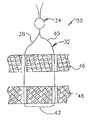
- FIG. 1is a schematic illustration depicting the manner in which layers of body tissue are moved into linear apposition with each other and secured with a suture and suture retainer;
- FIG. 2is a schematic fragmentary sectional view illustrating the manner in which the suture and suture retainer of FIG. 1 are positioned relative to each other;
- FIG. 3is a fragmentary schematic illustration depicting the manner in which ultrasonic vibratory energy is applied to the suture retainer of FIG. 2 ;
- FIG. 4is a schematic fragmentary sectional view of another embodiment of the invention and illustrating the approximation of layers of tissue by tensioning a suture with a predetermined force and pressing a suture retainer against the body tissue with a predetermined force;
- FIG. 5is a schematic fragmentary sectional view of another embodiment of the invention and illustrating the manner in a vibration applicator member engages a suture retainer which is being pressed against body tissue with a predetermined force while an associated suture is tensioned with a predetermined force;
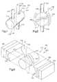
- FIG. 6is a schematic fragmentary pictorial illustration of another embodiment of the invention and depicting the construction of sections of a suture retainer and the relationship of the sections of the suture retainer to apparatus for applying ultrasonic vibratory energy to the suture retainer;
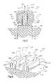
- FIG. 7is a schematic pictorial illustration of an embodiment of the invention in which a suture retainer has a pair of passages for receiving sections of a suture;
- FIG. 8is a schematic illustration depicting the manner in which ultrasonic vibratory energy is applied to the suture retainer of FIG. 7 ;
- FIG. 9is an exploded fragmentary schematic illustration of another embodiment of the invention and depicting the manner in which a suture is wrapped around a section of a suture retainer and the relationship of apparatus for applying ultrasonic vibratory energy to sections of the suture retainer;
- FIG. 10is a schematic pictorial illustration of another embodiment of the invention and depicting the manner in which sections of a suture extend through passages in a section of a suture retainer;
- FIG. 11is a schematic fragmentary sectional view depicting the relationship of the section of the suture retainer illustrated in FIG. 10 to other sections of the suture retainer and to an apparatus for applying ultrasonic vibratory energy to the suture retainer;
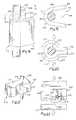
- FIG. 12is a schematic illustration of another embodiment of the invention and depicting the relationship between sections of a suture and sections of a suture retainer;
- FIG. 13is a top plan view, taken generally along the line 13 - 13 of FIG. 12 , illustrating the relationship of the sections of the suture retainer and suture to an apparatus for applying ultrasonic vibratory energy to the suture retainer;
- FIG. 14is a schematic illustration of another embodiment of the invention and depicting the manner in which sections of a suture are wrapped around a section of a suture retainer;
- FIG. 15is a schematic sectional view, taken generally along the line 15 - 15 of FIG. 14 , illustrating the relationship between sections of the suture retainer and an apparatus for applying ultrasonic vibratory energy to the suture retainer;
- FIG. 16is a schematic plan view of another embodiment of the invention, illustrating the relationship of sections of a suture to recesses formed in a suture retainer which is disposed between portions of an apparatus for applying ultrasonic vibratory energy to the suture retainer;
- FIG. 17is an enlarged fragmentary schematic illustration depicting the manner in which a section of the suture is moved into one of the recesses in the suture retainer of FIG. 16 ;
- FIG. 18is a schematic pictorial illustration depicting the manner in which another embodiment of the suture retainer is positioned relative to the suture;
- FIG. 19is a plan view, taken generally along the line 19 - 19 of FIG. 18 , illustrating the relationship between the suture retainer and the suture;
- FIG. 20is a plan view, generally similar to FIG. 19 , illustrating the relationship of an apparatus for applying ultrasonic vibratory energy to the suture retainer and the suture retainer and suture of FIG. 19 ;
- FIG. 21is a schematic pictorial illustration of an embodiment of the suture retainer having a recess which receives a portion of a suture;
- FIG. 22is a plan view of another embodiment of the invention and illustrating the manner in which a suture is positioned in a recess in the suture retainer and the relationship of apparatus for applying ultrasonic vibratory energy to the suture retainer;
- FIG. 23is a schematic illustration of another embodiment of the invention and depicting the manner in which a suture and a suture retainer are utilized to hold layers of body tissue in apposition with each other;
- FIG. 24is a schematic illustration of one apparatus for applying ultrasonic vibratory energy to a suture retainer
- FIG. 25is a schematic illustration of a second apparatus for applying ultrasonic vibratory energy to a suture retainer
- FIG. 26is a schematic illustration, similar to FIG. 1 , depicting the manner in which layers of body tissue are moved into linear apposition with each other and secured with a suture;
- FIG. 27is a schematic fragmentary sectional view illustrating the manner in which sections of the suture of FIG. 26 are positioned relative to each other and to apparatus which applies ultrasonic vibratory energy to the sections of the suture;
- FIG. 28is a schematic illustration depicting the manner in which sections of the suture of FIG. 27 are extended.
- a tissue securing system 30( FIG. 1 ) includes a suture 32 and a suture retainer or crimp 34 .
- the suture 32includes left and right sections 38 and 40 which are interconnected by a connector section 42 .
- the suture retainer 34grips the left and right sections 38 and 40 of the suture 32 .
- the tissue securing system 30is used in a sterile, operating room environment to secure upper and lower layers 46 and 48 of soft, human body tissue in linear apposition with each other.
- the two layers 46 and 48 of human body tissueare approximated and held against movement relative to each other by the suture 32 .
- the two layers 46 and 48 of body tissuehave been schematically illustrated in FIG. 1 as being spaced apart from each other, they are held in a side-by-side relationship with each other and pressed together by tightening the tissue securing system 30 . Pressing the two layers 46 and 48 together with the tissue securing system 30 promotes healing of the tissue.
- tissue securing system 30has been illustrated in FIG. 1 as being used to hold layers of soft tissue in linear apposition with each other, it is contemplated that the tissue securing system may be used in many different locations in a patient's body to secure tissue.
- the tissue securing system 30could be utilized to secure soft tissue, such as a ligament or tendon, against movement relative to a bone.
- the tissue securing system 30could be utilized to interconnect portions of a flexible conduit, such as a blood vessel or intestine. It should be understood that the tissue securing system 30 may be used with either hard body tissue, or soft body tissue, or both hard and soft body tissue.
- a force distribution membersuch as a button
- the force distribution memberwould distribute force over a relative large area of the lower layer 48 of body tissue.
- a force distribution membersuch as a button, could be utilized between the upper layer 46 of soft tissue and the left and right sections 38 and 40 of the suture 32 and the suture retainer 34 .
- the suture 32could extend through a suture anchor and/or be connected with body tissue in a manner similar to that disclosed in U.S. Pat. Nos. 5,584,862; 5,549,631; and/or 5,527,343.
- the suture 32could be connected with body tissue in a different manner if desired.
- the connector section 42could be eliminated. If this is done, the left section 38 of the suture 32 could be connected with one suture anchor and the right section 40 of the suture could be connected with a second suture anchor.
- the sections 38 and 40 of the suture 32could extend straight through the suture retainer 34 , in the illustrated embodiment of the invention, the sections 38 and 40 of the suture 32 are wrapped around portions of the suture retainer 34 .
- the left section 38 of the suture 32is wrapped around a portion 52 ( FIG. 2 ) of the suture retainer 34 .
- the right section 40 of the sutureis wrapped around a portion 54 of the suture retainer 34 .
- the left section 38 of the suture 32is wrapped for more than a complete turn around the portion 52 of the suture retainer and the right section 40 of the suture is wrapped for more than a complete turn around the portion 54 of the suture retainer.
- wrapping of the sections 38 and 40 of the suture 32 around the suture retainer 34could be omitted or each of the sections of the suture could be wrapped for less than one complete turn around a portion of the suture retainer.
- bends 58 , 60 , 62 and 64are formed in the section 38 of the suture 32 as it is wrapped around the portion 52 of the suture retainer 34 .
- bends 66 , 68 , 70 and 72are formed in the section 40 of the suture 32 as it is wrapped around the portion 54 of the suture retainer 34 .
- a greater number of bendswould be formed in each of the sections 38 and 40 of the suture 32 if they were wrapped a greater number of times around the suture retainer 34 .
- the suture retainer 34could have many different constructions and configurations, in the illustrated embodiment of the invention, the suture retainer 34 is integrally formed as one piece and has a spherical configuration.
- a cylindrical central passage 76extends axially through the suture retainer 34 between upper and lower (as viewed in FIG. 2 ) polar regions of the spherical suture retainer.
- the two sections 38 and 40 of the suture 32extend through the passage 76 .
- the suture retainer 34is formed separately from the suture 32 and is initially disconnected from the suture.
- two lengths of the left suture section 38 and two lengths of the right suture section 40extend through the passage 76 as a result of the wrapping of the sections of the suture around the portions 52 and 54 of the suture retainer 34 .
- the two sections 38 and 40 of the suture 32could extend straight through the passage 76 without being wrapped around the portions 52 and 54 of the suture retainer 34 . If this was done, only a single length of the left section 38 of the suture 32 would be disposed in the passage 76 adjacent to a single length of the right section 40 of the suture 32 .
- a pair of grooves or recesses 80 and 82extend radially inward from a spherical outer side surface 84 of the suture retainer 34 .
- the grooves or recesses 80 and 82are relatively deep so that the portions 52 and 54 of the suture retainer around which the suture is wrapped are relatively slender. This results in relatively short lengths of the sections 38 and 40 of the suture being disposed in engagement with the outer side surface of the suture retainer 34 adjacent to the upper and lower polar regions of the suture retainer.
- the grooves or recesses 80 and 82extend inward from the outer side surface 84 of the suture retainer 34 .
- the depth of the grooves or recesses 80 and 82varies along the vertical (as viewed in FIG. 2 ) length of the grooves.
- the grooves 80 and 82could be constructed so as to have a uniform depth throughout their length. If this was done, the grooves 80 and 82 would have an arcuate configuration with centers of curvature which are coincident with the center of curvature of the spherical outer side surface 84 of the suture retainer 34 .
- the grooves 80 and 82could be undercut to enclose the portions of the suture 32 disposed in the grooves. It is contemplated that the grooves could have any one of the groove configurations disclosed in U.S. Pat. No. 6,010,525. The disclosure from the aforementioned U.S. Pat. No. 6,010,525 is incorporated herein in its entirety by this reference thereto. Alternatively, the grooves 80 and 82 could be formed as passages which extend through the suture retainer 34 parallel to and spaced apart from the central passage 76 .
- the suture retainer 34may be formed of many different materials. However, it is contemplated that it will be preferred to form the suture retainer 34 of a biodegradable polymer.
- a biodegradable polymerwhich may be utilized is polycaperlactone.
- the suture retainer 34could be formed of polyethylene oxide terephthalate or polybutylene terephthalate.
- the suture retainer 34could be formed as a polyhydroxyalkanoate if desired. It is also contemplated that other biodegradable or other bioerodible copolymers could be utilized if desired.
- the suture retainer 34could be formed of a material which is not biodegradable.
- the suture retainer 34could be formed of an acetyl resin, such as “Delrin” (trademark).
- the suture retainer 34could be formed of a para-dimethylamino-benzenediazo sodium sulfonate, such as “Dexon” (trademark).
- the suture retainer 34could be formed of nylon.
- the suture 32may be formed of the same material as the suture retainer 34 or of a different material.
- the suture 32may be formed of natural or synthetic materials.
- the suture 32may be a monofilament or may be formed of a plurality of interconnected filaments.
- the suture 32may be biodegradable or non-biodegradable. It is contemplated that the suture retainer 34 could be utilized in association with force transmitting elements other than a suture. It is believed that it may be preferred to form the suture 32 of the same material as the suture retainer 34 .
- ultrasonic vibratory energyis utilized to cause the suture retainer 34 to grip the suture 32 .
- the ultrasonic vibratory energyis at a frequency above that which can normally be detected by the human ear, that is, above 16 to 20 kilohertz. Although there are a wide range of frequencies which may be utilized, it is believed that it will be desirable to use ultrasonic energy having a frequency of between 20 kilohertz and 70 kilohertz. However, higher frequency vibratory energy could be utilized if desired.
- the ultrasonic vibratory energymay be continuously applied, pulsed or modulated in various fashions. Any one of many known transducers may be utilized to change electrical energy into mechanical vibrations having an ultrasonic frequency.
- the transducersmay be piezoelectric, ferroelectric, or magnetostrictive.
- One commercial source of apparatus which may be utilized to provide ultrasonic vibratory energyis Dukane Corporation, Ultrasonics Division, 2900 Dukane Drive, St. Charles, Ill. Of course, there are other sources of apparatus which can be utilized to provide ultrasonic vibratory energy.
- the ultrasonic vibratory energycreates frictional heat at the areas where the suture retainer 34 and suture 32 are disposed in engagement with each other.
- the frictional heat provided by the ultrasonic vibratory energyis effective to heat the material of the suture retainer 34 into its transition temperature range while the material of the suture 32 remains at a temperature close to or below its transition temperature range.
- the suture 32may be formed of a material having a transition temperature range which is above 190 degrees Celsius.
- the suture retainer 34may have a transition temperature range which, for the most part, is at a temperature below 190 degrees Celsius.
- transition temperature range for the suture 32could be co-extensive with the transition range for the suture retainer 34 .
- the transition temperature range of the suture 32could extend below the transition temperature range of the suture retainer 34 .
- the plastic material of the suture retainer 34loses its rigidity and becomes soft and viscous.
- the softened material of the suture retaineris moldable and flows, when subjected to pressure, around the suture 32 without significant deformation of the suture.
- the temperature range into which the suture 32 is heated and the pressure applied against the suturemay result in some deformation of the suture.
- the suture 32 and suture retainer 34may be made of many different materials
- the suture and suture retainermay be formed of a plastic material which is a biopolymer.
- the suture 32 and/or suture retainer 34may be formed of polyglycolide which is commercial available under the trademark “Dexon”. Polyglycolide is a crystalline material that melts at about 225° Celsius.
- the suturecould be formed of a glycolide-based copolymer which is commercially available under the trademark “Vicryl”.
- the suture retainer 34is also made of a plastic material which may be a biopolymer.
- the suture retainer 34may be made of polydellactide.
- the transition temperature of polydellactidewill vary depending upon the specific characteristics of the material. However, a suture retainer 34 formed of polydellactide may have a transition temperature range of about 75° Celsius to about 120° Celsius.
- Other materials which may be utilized for forming the suture 32 and/or suture retainer 34are disclosed in U.S. Pat. No. 5,735,875. The disclosure in the aforementioned U.S. Pat. No. 5,735,875 is hereby incorporated herein in its entirety by this reference thereto.
- both the suture and suture retainermay be formed of the same amorphous thermoplastic material.
- both the suture 32 and suture retainer 34may be formed of a polyhydroxy-alkanoate.
- both the suture 32 and suture retainer 34may be formed of nylon. It is contemplated that the suture 32 and suture retainer 34 could be formed of different amorphous polymers which are similar, that is, have the same or similar chemical properties.
- a supportive member or anvil 90( FIG. 3 ) is positioned in engagement with one side of the suture retainer 34 .
- a horn or acoustic tool 92is positioned in engagement with the opposite side of the suture retainer 34 .
- Forceindicated schematically by arrows 96 and 98 in FIG. 3 , is applied against the suture retainer 34 by the anvil 90 and horn 92 .
- the hornis vibrated, horizontally as viewed in FIG. 3 , at a rate in excess of 20 kilohertz.
- the horn 92may be vibrated at any desired frequency within range of 20 kilohertz to 70 kilohertz, it is believed that it may be desirable to vibrate the horn 92 at a rate which is close to or greater than 70 kilohertz.
- the horn 92is vibrated for a dwell time which is sufficient to transmit enough ultrasonic vibratory energy to the suture retainer 34 to heat at least a portion of the material of the suture retainer 34 into its transition temperature range.
- the vibration of the horn 92is then interrupted and the material of the suture retainer 34 begins to cool.
- the clamping forceindicated by the arrows 96 and 98 , is maintained against opposite sides of the suture retainer 34 by the anvil 90 and horn 92 during the time which ultrasonic vibratory energy is transmitted from the horn 92 to the material of the suture retainer 34 .
- the clamping forceindicated schematically by the arrows 96 and 98 and applied by the anvil 90 and horn 92 , is maintained for a predetermined amount of time sufficient to allow the material of the suture retainer to cool and bond to both itself and the suture 32 .
- the force, indicated schematically by the arrows 96 and 98 in FIG. 3 , applied by the anvil 90 and horn 92 to the suture retainer 34may be increased as the transmission of ultrasonic vibratory energy to the suture retainer 34 from the horn 92 is interrupted.
- the force, indicated schematically by the arrows 96 and 98 in FIG. 3is sufficient to cause the passage 76 and recesses 80 and 82 to collapse as the suture retainer 34 is heated by ultrasonic vibratory energy and subsequently allowed to cool.
- the length of time for which ultrasonic vibratory energy is transmitted to the suture retainer 34may vary as a function of the amplitude and frequency of the ultrasonic vibratory energy transmitted to the suture retainer. It is contemplated that the frequency of the ultrasonic vibratory energy will be in a range of between 20 kilohertz and 70 kilohertz. It is contemplated that the amplitude of the ultrasonic vibrations may vary within a range of 0.0008 inches to 0.0050 inches depending upon the design of the suture retainer 34 and the material forming the suture retainer.
- the force, indicated schematically by the arrows 96 and 98 , applied against the suture retainer 34may vary depending upon the construction of the suture retainer 34 and the material forming the suture retainer. For example, a force of approximately 1-15 pounds may be applied against the suture retainer 34 by both the anvil 90 and horn 92 . However, the amount of force which is applied will probably be different for different suture retainers and different horns 92 .
- the ultrasonic vibratory energymay be transmitted from the horn 92 to the suture retainer 34 for a period of time which varies between 0.25 seconds and 1.0 second. After the transmission of ultrasonic vibratory energy has been interrupted, the force, indicated by the arrows 96 and 98 , may continue to be applied to the suture retainer 34 by the anvil 90 and horn 92 for approximately 1.0 seconds.
- the extent to which the suture retainer 34 is compressed by the force 96 and 98 applied against the suture retainer by the anvil 90 and horn 92has been illustrated schematically in FIG. 3 . It is contemplated that the distance through which the anvil 90 and horn 92 move toward each other to compress the suture retainer 34 may be from 0.010 inches to 0.050 inches. Of course, the distance through which the suture retainer 34 is compressed by the anvil 90 and horn 92 may be different for suture retainers having different constructions and/or formed of different materials.
- the suture 32When the two layers 46 and 48 of body tissue are to be held in position relative to each other by the tissue securing system 30 , the suture 32 is positioned relative to the layers of body tissue.
- the left and right sections 38 and 40 of the suture 32extend through the two layers 46 and 48 of tissue.
- the sections 38 and 40 of the suture 32have been illustrated schematically in FIG. 1 as extending through passages in the layers 46 and 48 of body tissue, the passages could be omitted and the suture 32 sewn through the body tissue without forming passages in the body tissue.
- the sections 38 and 40 of the suture 32are interconnected by the connector section 42 which extends along one side of the layer 48 of body tissue.
- the sections 38 and 40 of the suture 32could be connected with a single anchor embedded in either hard or soft body tissue.
- a separate anchorcould be provided for each of the sections 38 and 40 of the suture 32 .
- These anchorscould be embedded in the body tissue or disposed adjacent to one side of the body tissue.
- the suture retainer 34is then connected with the suture 32 .
- the left (as viewed in FIG. 2 ) section 38 of the sutureis inserted through the central passage 76 in the suture retainer 34 .
- the left section 38 of the suture 32is then wrapped around the portion 52 of the suture retainer 34 and again inserted through the central passage 76 .
- the right section 40 of the suture 32is inserted through the central passage 76 and wrapped around the portion 54 of the suture retainer 34 .
- the right section 40 of the sutureis then inserted through the central passage 76 for a second time. This results in the suture 32 being connected with the suture retainer 34 in the manner illustrated schematically in FIG. 2 .
- the suture retainer 34is then moved downward (as viewed in FIGS. 1 and 2 ) along the suture 32 toward the upper layer 46 of body tissue.
- the suture 32is tensioned with a predetermined force during downward movement of the suture retainer 34 toward the body tissue.
- the suture retainer 34moves downward (as viewed in FIGS. 1 and 2 ) along the suture 32 toward the upper layer 46 of body tissue, the turns formed in the sections of the suture around the portions 52 and 54 of the suture retainer 34 move downward toward the body tissue.
- the bends 58 - 64 in the section 38 of the suture 32 and the bends 66 - 72 in the section 40 of the suture 32move along the suture toward the upper layer 46 of body tissue with the suture retainer 34 .
- a predetermined tensionindicated by arrows 102 and 104 in FIG. 3 , is maintained in the sections 38 and 40 of the suture 32 .
- the magnitude of the tension forces 102 and 104 in the sections 38 and 40 of the suture 32is selected as a function of the characteristics of the layers 46 and 48 of body tissue and as a function of the strength of the suture.
- the suture retainer 34moves downward (as viewed in FIGS. 1-3 ), the leading portion of the suture retainer moves into engagement with the upper layer 46 of body tissue ( FIG. 3 ). The suture retainer 34 is then pressed against the upper layer 46 of body tissue. If desired, a force distribution member, such as a button, could be provided between the suture retainer 34 and the body tissue 46 .
- the suture retainer 34is pressed downward against the body tissue 46 with a predetermined force, indicated schematically by an arrow 106 in FIG. 3 , while a predetermined tension, indicated schematically by the arrows 102 and 104 , is maintained in the suture 32 .
- the force transmitted from the suture 32 and suture retainer 34 to the layers 46 and 48 of body tissuepresses them together and, to some extent, compresses the layers of body tissue. This results in the layers of body tissue being held in linear apposition and being compressed to promote healing of the layers 46 and 48 of body tissue.
- the force, indicated by the arrows 102 and 104 , with which the sections 38 and 40 of the suture 32 are tensioned,may vary depending upon the material from which the suture is constructed and the size of the suture. By consulting a chart, a surgeon can select a suture size and strength suitable for a particular use. Thus, a relatively large suture having substantial strength may be selected when body tissue is to be connected with a bone or when portions of a bone are to be interconnected by the suture. On the other hand, a relatively small suture size having a relatively small strength may be selected when delicate body tissue, such as stomach or intestinal tissue, is to be interconnected with the suture.
- the tension forces 102 and 104 in the sections 38 and 40are determined as a function of the strength 32 of the suture and the characteristics of the body tissue through which the suture extends.
- the suture 34is pressed against the body tissue with a force which is also a function of the size and strength of the suture 32 and the characteristics of the body tissue 46 and 48 .
- a forcewhich is also a function of the size and strength of the suture 32 and the characteristics of the body tissue 46 and 48 .
- One way in which force with which the suture 32 is tensioned and with which the suture 34 is pressed against body tissueis disclosed in U.S. patent application Ser. No. 09/348,940 filed Jul. 7, 1999 by Peter M. Bonutti et al. and entitled “Method and Apparatus for Securing a Suture”.
- the disclosure in the aforementioned U.S. patent application Ser. No. 09/348,940is hereby incorporated herein by this reference thereto.
- ultrasonic vibratory energyis applied to the suture retainer.
- the anvil 90FIG. 3
- the horn 92is positioned in engagement with the opposite side of the suture retainer.
- the anvil 90 and horn 92are urged toward each other with a predetermined force, indicated schematically by the arrows 96 and 98 in FIG. 3 .
- the specific magnitude of the force 96 and 98will vary depending upon the composition of the suture retainer 34 and the construction of the suture retainer. In addition, the magnitude of the force 96 and 98 will vary as a function of the desired extent of deformation of the suture retainer 34 .
- the suture retainer 34has been heat softened by ultrasonic vibratory energy, the material of the suture retainer is pliable and is plastically deformed by the force applied against the suture retainer by the anvil 90 and horn 92 .
- the apparatus for transmitting ultrasonic vibratory energy to the suture retainer 34includes a generator (not shown) which changes standard electrical power into electrical energy at the desired ultrasonic frequency.
- a transducer(not shown) changes the electrical energy into low amplitude mechanical motion or vibration. These vibrations are transmitted to a booster which is used to increase or decrease the amplitude of the vibrations. The vibrations are then transmitted to the horn 92 .
- the ultrasonic vibratory energy transmitted to the suture retainer 34 from the horn 92is converted into heat energy.
- the temperature of the material forming the suture retainer 34increases.
- the heattends to concentrate at a boundary between the suture 32 and the suture retainer 34 .
- the heattends to concentrate in the areas where the suture 32 engages the grooves 80 and 82 and the passage 76 ( FIG. 2 ).
- the material of the suture retainer 34As the temperature of the suture retainer 34 increases, the material of the suture retainer is heated into the transition temperature range and softens. However, the material of the suture retainer 34 does not melt and become liquid. As the material of the suture retainer 34 softens, the forces 96 and 98 ( FIG. 3 ) applied against the suture retainer cause the material of the suture retainer to flow or ooze around and engage the suture 32 .
- the grooves 80 and 82close, that is, collapse.
- the central passage 76also closes.
- the softened material of the suture retainer 34moves into engagement with the suture ( FIG. 3 ).
- the viscous material of the suture retainer 34engages the suture 32 and bonds to the suture without significant deformation of the suture.
- the materials of the suture 32 and suture retainer 34should be chemically compatible so that a molecular bond can be established between the suture retainer and the suture.
- Like materialsthat is materials having chemical properties which are the same or very similar will usually bond together. However, dissimilar materials may bond if their melt temperatures are reasonably close and they are of like molecular structure. Generally speaking, amorphous polymers are readily bonded to each other.
- the suture retainer 34is formed separately from the suture 32 . As the material of the suture retainer 34 bonds to the suture 32 , the suture retainer 34 becomes fixedly connected to the suture.
- heatmay be transmitted directly to the suture retainer 34 during the transmission of ultrasonic vibratory energy to the suture retainer.
- the heatmay be transmitted from a heating element disposed in the anvil 90 and/or the horn 92 .
- a separate membercould be utilized to transmit heat to the suture retainer 34 .
- the anvil 90 and horn 92have a configuration which corresponds to the arcuate configuration of the spherical outer side surface 84 ( FIG. 2 ) of the suture retainer 34 .
- the anvil 90 and horn 92are configured so as to engage the material of the suture retainer 34 and to be spaced from the suture 32 . This is to prevent excessive heating of the material of the suture 32 by the direct application of ultrasonic vibratory energy to the suture.
- sections 38 and 40 of the suture 32are wrapped around portions 52 and 54 of the suture retainer 34 .
- a single section of the sutureextends straight through a passage in the suture retainer. Since the embodiment of the invention illustrated in FIG. 4 is generally similar to the embodiment of the invention illustrated in FIGS. 1-3 , similar terminology will be utilized to designate similar components. It should be understood that one or more of the features of any of the various embodiments of the invention disclosed herein may be used with the embodiment of the invention illustrated in FIG. 4 .
- a suture 112is inserted through upper and lower (as viewed in FIG. 4 ) layers 114 and 116 of human body tissue in a sterile operating room environment.
- a first or inner end portion 118 of the suture 112is connected with a suture anchor 120 .
- the suture anchor 120could have any desired construction, including the construction disclosed in U.S. Pat. Nos. 5,584,862; 5,549,631; and/or 5,527,343.
- the illustrated embodiment of the suture anchor 120is a circular disc or button having a pair of central openings around which the end portion 118 of the suture 112 is tied.
- the suture 112extends straight through the lower layer 116 and upper layer 114 of body tissue.
- the two layers of body tissueare disposed in linear apposition with each other and are compressed between the suture anchor 120 and a suture retainer 124 .
- the upper and lower layers 114 and 116 of body tissueare compressed by force applied against the body tissue by the suture retainer 124 and suture anchor 120 .
- the layers 114 and 116are layers of soft body tissue
- the suture 112 , suture anchor 120 , and suture retainer 124could be used with hard body tissue in the manner disclosed in U.S. Pat. No. 5,921,986.
- the suture 112 , suture anchor 120 , and suture retainer 124could be used to connect soft body tissue with hard body tissue.
- the suture retainer 124has a spherical configuration and is formed separately from the suture 112 .
- a cylindrical passage 126extends axially through the suture retainer 124 .
- the suture 112extends straight through the passage 126 in the suture retainer 124 , bends and/or loops could be formed in the suture 112 around the suture retainer 124 .
- the suture retainer 124is formed of one piece of spherical polymeric material having a relatively low coefficient of friction.
- the suture retainer 124may be formed of many different materials. However, it is believed that it may be preferred to form the suture retainer 124 of a biodegradable polymer such as polycaperlactone or polyhydroxyalkanoate. It is contemplated that other biodegradable or bioerodible polymers could be utilized if desired. It is believed that it may be preferred to form the suture retainer 124 of an amorphous thermoplastic material.
- the suture 112may be a monofilament or may be formed of a plurality of interconnected filaments.
- the suture 112may be biodegradable or non-biodegradable. It is believed that it will be preferred to form the suture 112 of the same material as the suture retainer 124 . However, the suture 112 could be formed of a material which is different than the material of the suture retainer.
- the suture 112may be formed of an amorphous thermoplastic having chemical properties which are the same or similar to the chemical properties of the suture retainer 124 .
- both the suture retainer 124 and the suture 112may be formed of the same biodegradable polymer, such as polycaperlactone or polyhydroxyalkanoate.
- the suture 112is tensioned with a force which is a function of the size and strength of the suture.
- the suture retainer 124is pressed against the upper layer 114 of body tissue with a force which is a function of the size and strength of the suture 112 .
- a force distribution member or buttoncould be positioned between the suture retainer and the upper layer 114 of body tissue.
- the suture 112is tensioned by a force application assembly 130 which is connected with a second our outer end portion 132 of the suture 112 .
- the force application assembly 130includes a transducer or load cell 134 which provides an output signal indicative of a force, indicated schematically at 136 in FIG. 4 , which is applied to the second or outer end portion 132 of the suture 112 .
- the force 136has a magnitude which is a function of the size and strength of the suture 112 and the characteristics of the body tissue with which the suture is associated, that is, the upper layer 114 and lower layer 116 of body tissue.
- the suture retainer 124is pressed against the body tissue with a force which is also a function of the strength and size of the suture 112 .
- a force application member 140is used to apply force against the suture retainer 124 .
- the force application member 140has a cylindrical opening 142 which extends through the force application member.
- the suture 112extends through the opening 142 in the force application member 140 .
- a slotmay be formed in the force application member 140 to enable the suture to be moved into the opening 142 .
- the suture 112could be inserted through the opening 142 before the end portion of the suture is connected with the force application assembly 130 .
- Forcesare applied against opposite end portions 150 and 152 of the force application member 140 to press the suture retainer 124 against the upper layer 114 of body tissue or against a force transmitting member disposed between the suture retainer 124 and the upper layer 114 of body tissue.
- the combined force indicated schematically by the arrows 146 and 148 in FIG. 4is a function of the size and strength of the suture 112 and the characteristics of the layers 114 and 116 of body tissue. It is contemplated that the combined forces 146 and 148 may be equal to the force 136 . Alternatively, the summation of the forces 146 and 148 could exceed the force 136 or be less than the force 136 .
- the suture retainer 124slides downward (as viewed in FIG. 4 ) along the suture 112 under the influence of the force application member 140 .
- the suture 112is tensioned by the force application assembly 130 so that the portion of the suture extending between the suture anchor 120 and the force application assembly 130 is straight, as illustrated in FIG. 4 .
- the force which is applied to the outer end portion 132 by the force transmitting assemblymay be substantially less than the force which is indicated schematically by the arrow 136 in FIG. 4 .
- the force applied against the suture retainer by the force application member 140is increased.
- the force applied to the outer end portion 132 of the suture 112 by the force application assembly 130is increased.
- the force applied against the suture retainer by the force application member 140is increased until the force, indicated schematically by the arrows 146 and 148 in FIG. 4 , is equal to a predetermined force which is a function of the strength of the suture 112 and the characteristics of the layers 114 and 116 of body tissue.
- the force applied to the outer end portion 132 of the suture 112 by the force application assembly 130is increased to the force indicated schematically by the arrow 136 in FIG. 4 .
- the force indicated by the arrow 136is a predetermined function of the strength of the suture 112 and the characteristics of the layers 114 and 116 of body tissue.
- the suture retainer 124is heated to grip the suture 112 .
- the suture retainer 124is heated by the application of ultrasonic vibratory energy to the suture retainer.
- the ultrasonic vibratory energyis converted into heat by the molecules of the suture retainer 124 .
- the mechanical ultrasonic vibrations applied against the suture retainer 124cause molecular vibration of the material of the suture retainer and a heating of the suture retainer.
- the application of ultrasonic vibratory energy to the suture retainer 124is interrupted. Heating the material forming the suture retainer 124 causes the material to lose its rigidity and soften. The material of the suture retainer 124 is not melted and does not become liquid by being heated into its transition temperature range. The softened material of the suture retainer 124 bonds to the suture 112 without significant deformation of the suture.
- a support member or anvil 160engages one side, that is the left side as viewed in FIG. 4 , of the suture retainer 124 .
- a horn or acoustic toolis pressed against the opposite or right side (as viewed in FIG. 4 ) of the suture retainer 124 .
- the anvil 160 and horn 162are pressed against opposite sides of the suture retainer 124 with predetermined forces, indicated schematically by arrows 164 and 166 in FIG. 4 .
- the hornis vibrated with an ultrasonic frequency, that is with a frequency which is greater than 20 kilohertz. It is contemplated that the horn 162 may be vibrated at a selected frequency within a range of ultrasonic frequencies which extends between 20 kilohertz and 70 kilohertz.
- the particular ultrasonic frequency with which the horn 162 is vibratedwill vary depending upon the composition and construction of the suture retainer 124 , it is believed that it may be preferred to vibrate the horn 162 with a frequency which is close to or greater than 70 kilohertz.
- the mechanical vibrations applied to the suture retainer 124 by the horn 162are effective to heat a portion of the material of the suture retainer 124 into the transition temperature range. The heat tends to concentrate on the portion of the suture retainer 124 adjacent to the passage 126 and the suture 112 .
- the application of ultrasonic vibratory energy to the suture retainer 124is interrupted.
- the forces 164 and 166are effective to close or collapse the passage 126 and to press the softened material of the suture retainer 124 against the suture 112 .
- the anvil 160 and horn 162continue to apply the forces 164 and 166 against the softened material of the suture retainer. If desired, the forces 164 and 166 may be increased when the application of ultrasonic vibratory energy to the suture retainer 124 by the horn 162 is interrupted.
- the forces 164 and 166firmly press the heat-softened material of the suture retainer 124 into the passage 126 to collapse the passage.
- the heat softened material of the suture retainer 124is plastically deformed and pressed against the suture 112 by the forces 164 and 166 applied against the suture retainer by the anvil 160 and horn 162 .
- the forces 164 and 166are maintained for a sufficient period of time to enable the material of the suture retainer 124 to bond to the suture 112 without significant deformation of the suture. Once this bonding has been achieved, application of the forces 164 and 166 is interrupted and the anvil 160 and horn 162 are withdrawn. The force application member 140 may then be disengaged from the suture retainer and the force application assembly 130 disconnected from the outer end portion 132 of the suture 112 .
- the upper layer 114is moved into apposition with the lower layer 116 of body tissue.
- the suture 112is then connected with the suture anchor 120 and is inserted through the layers 114 and 116 of body tissue with a suitable needle.
- the outer end portion 132 of the suture 112is then inserted through the passage 126 .
- the suture retainer 124is then moved along the suture 112 into engagement with the upper layer 114 of body tissue.
- the force application member 140is utilized to transmit the forces 146 and 148 to the suture retainer 124 to press the suture retainer against the upper layer 114 of body tissue. This results in the two layers 114 and 116 of body tissue being pressed firmly together between the suture retainer 124 and suture anchor 112 .
- the forces 146 and 148are transmitted to the suture retainer 124 through the force application member 140 .
- the suture 112is tensioned with a force 136 by the force application assembly 130 .
- the anvil 160 and horn 162then compress the suture retainer 124 under the influence of the forces 164 and 166 .
- Ultrasonic vibratory energyis transmitted to the suture retainer.
- the transmission of ultrasonic energy to the suture retaineris interrupted and a bonding of the material of the suture retainer to the suture 112 occurs.
- the application of the forces 164 and 166is interrupted.
- the suture retainerhas been heated by only the application of ultrasonic vibratory energy to the suture retainer.
- heat energycould be transmitted directly to the suture retainer along with the ultrasonic vibratory energy. If this was to be done, a heating element could be provided in the anvil 160 and/or horn 162 . If desired, a separate heating element could engage the suture retainer to transmit the heat to the suture retainer separately from the anvil 160 and horn 162 .
- anvil 160 and horn 162engage the suture retainer 124 at locations spaced from the suture 112 to prevent excessive heating of the material of the suture.
- protective collarscould be provided around the suture 112 at opposite ends of the passage 126 .
- a single section of the suture 112extends through a single passage 126 in the suture retainer 124 .
- ultrasonic vibratory energyis applied to the suture retainer 124 by the horn 162 which also applies a compressive force 166 against the suture retainer.
- a plurality of sections of the sutureextend through a plurality of passages in the suture retainer.
- ultrasonic vibratory energyis applied to the suture retainer by a member which is separate from the members which apply force against opposite sides of the suture retainer.
- FIGS. 1-4are similar to the embodiment of the suture retainer illustrated in FIG. 5 , similar terminology will be utilized to designate similar components. It should be understood that one or more of the features of any of the embodiments of the invention disclosed herein may be used with the embodiment of the invention illustrated in FIG. 5 .
- a tissue securing system 174is used in a sterile, operating room environment and includes a suture 176 and a suture retainer 178 .
- the suture 176has left and right sections 182 and 184 which extend into human body tissue 186 .
- the body tissue 186may include a plurality of layers which are approximated in linear apposition with each other in the manner previously described in conjunction with the embodiment of the invention illustrated in FIG. 1 .
- the suture 176has been illustrated in FIG. 5 in association with soft body tissue 186 , it is contemplated that the suture 176 could be associated with hard or hard and soft body tissue.
- the suture sections 182 and 184are interconnected by a connector section which engages the body tissue in the manner illustrated schematically in FIG. 1 .
- the suture 176could be associated with a suture anchor, similar to the suture anchor 120 of FIG. 4 , if desired. Rather than being disposed in engagement with an outer side surface of a layer of body tissue, the suture anchor could be embedded in the body tissue.
- the suture retainer 178has a spherical configuration and is formed separately from the suture 176 .
- a pair of parallel passages 190 and 192extend through the suture retainer 178 at locations offset to opposite sides of a central or polar axis of the suture retainer.
- a force transmitting member 194is provided between the suture retainer 178 and the body tissue 186 .
- the sections 182 and 184 of the suture 176press against opposite sides of the force transmitting member 194 .
- the force transmitting member 194could be provided with grooves or passages to receive the sections 182 and 184 of the suture 176 .
- the force transmitting member 194could be integrally formed as one piece with the suture retainer 178 . Both the force transmitting member 194 and suture retainer 178 are formed separately from the suture 176 .
- ultrasonic vibratory energyis applied to the suture retainer 178 by a horn or acoustic tool 200 .
- the horn 200extends into a cylindrical passage 202 formed in the suture retainer 178 .
- the passage 202extends parallel to and is disposed midway between the passages 190 and 192 which receive the sections 182 and 184 of the suture 176 .
- the horn 200has a generally cylindrical configuration which corresponds to the cylindrical configuration of the passage 202 .
- the horn 200 and passage 202could have different configurations if desired.
- the horn 200 and passage 202could have frustroconical configurations.
- a pair of force application members or anvils 206 and 208are pressed against opposite sides of the suture retainer 178 with predetermined forces, indicated schematically by arrows 210 and 212 in FIG. 5 .
- the anvils 206 and 208have arcuate configurations which correspond to the arcuate configuration of the suture retainer 178 .
- the anvils 206 and 208could have a different configuration if desired.
- the suture 176is positioned relative to the body tissue in the manner illustrated schematically in FIG. 1 .
- a separate anchorsimilar to the anchor 120 of FIG. 4 , could be connected with an end portion of each of the sections 182 and 184 of the suture 176 . If this was done, the sections 182 and 184 of the suture 176 could be separate from each other and interconnected by the body tissue 176 and suture retainer 178 . Thus, two separate segments of suture, that is the sections 182 and 184 , would be interconnected by a single suture retainer.
- the upper (as viewed in FIG. 5 ) end portions of the sections 182 and 184 of the suture 176are inserted through the passages 190 and 192 .
- the force distribution member 194is positioned between the suture retainer 178 and the body tissue 176 .
- the sections 182 and 184 of the sutureare then tensioned with a predetermined force.
- the suture retainer 178is moved along the sections 182 and 184 of the suture 176 into engagement with the force distribution member 194 .
- a predetermined forceis applied against suture retainer 178 , in the manner similar to that indicated schematically in FIG. 4 , to press the force transmitting member 194 against the body tissue 186 with a predetermined force.
- the sections 182 and 184 of the suture 176are tensioned with a predetermined force. If the sections 182 and 184 are formed by a single piece of suture 176 , in the manner illustrated schematically in FIG. 1 , a connector section of the suture is pulled against the body tissue to compress the body tissue between the suture retainer 178 and the connector section of the suture.
- the two spaced apart suture anchorsare pulled against the body tissue to compress the body tissue 186 between the suture anchors and the suture retainer 178 .
- the suture retainer 178While the suture 176 is being tensioned with a predetermined force and while the suture retainer 178 is being pressed against the force distribution member 194 with a predetermined force, the suture retainer 178 is deformed to grip the sections 182 and 184 of the suture 176 . This deformation of the suture retainer 178 results in a firm gripping of the sections 182 and 184 of the suture 176 to maintain a desired tension force in the suture and to maintain a desired compression force against the body tissue 186 .
- the anvils 206 and 208are pressed against opposite sides of the suture retainer with a predetermined force, as indicated schematically by the arrows 210 and 210 in FIG. 5 .
- the horn 200is then vibrated with an ultrasonic frequency to transmit ultrasonic vibratory energy to the suture retainer 178 . It is contemplated that the horn 200 may be vibrated at a frequency of between 20 and 70 kilohertz. It is believed that it may be preferred to vibrate the horn 200 at a frequency which is close to or greater than 70 kilohertz.
- Vibration of the horn 200 at ultrasonic frequenciestransmits mechanical vibrational energy form the horn 200 to the suture retainer 178 .
- This ultrasonic vibrational energyis converted into heat energy and results in a heating of the suture retainer 178 .
- the heat in the suture retainertends to be concentrated in the material of the suture retainer at locations adjacent to the passages 190 and 192 .
- the material of the suture retainer 178 adjacent to the passages 190 and 192has been heated into a transition temperature range for the material, the material of the suture retainer becomes soft and relatively pliable. However, the material of the suture retainer 178 does not melt and become liquid.
- the transmission of ultrasonic vibratory energy from the horn 200 to the suture retainer 178is then interrupted.
- the anvils 206 and 208continue to be pressed against the suture retainer 178 with the forces indicated schematically by the arrows 210 and 212 in FIG. 5 .
- the force applied against the suture retainer 178may be increased upon interruption of the transmission of ultrasonic vibratory energy to the suture retainer.
- the force 210 and 212 applied by the anvils 206 and 208 against the suture retainer 178is effective to plastically deform the heat softened material of the suture retainer.
- the force applied by the anvils 206 and 208collapses the passages 190 and 192 and presses the softened material of the suture retainer 178 against the sections 182 and 184 of the suture 176 .
- the suture retainer 178 and suture 176may be formed of many different materials. However, it is believed that it will be preferred to form the suture retainer 178 and the suture 176 of a biodegradable polymer.
- the biodegradable polymermay advantageously be an amorphous thermoplastic. Bonding of the material of the suture retainer 178 with the material of the suture 176 is promoted by forming the suture retainer and suture of the same material.
- the suture retainer 178 and suture 176could be formed of different materials having similar chemical properties and which are compatible with each other.
- the material of the suture retainer 178is heated by the application of ultrasonic vibratory energy to the suture retainer by the horn 200 .
- heat energycould be directly transmitted to the suture retainer 178 during the transmission of ultrasonic vibratory energy to the suture retainer if desired.
- heating elementscould be provided in the anvils 206 and 208 .
- the suture retainerhas a generally spherical configuration and is formed as one piece. In the embodiment of the invention illustrated in FIG. 6 , the suture retainer is formed as two pieces. Since the suture retainer of FIG. 6 is similar to the suture retainers of FIGS. 1-5 , similar terminology will be utilized to identify similar components. It should be understood that one or more features of other embodiments of the invention disclosed herein could be used with the embodiment of the invention illustrated in FIG. 6 .
- a tissue securing system 218( FIG. 6 ) is used in a sterile, operating room environment and includes a suture retainer 220 and suture 228 .
- the suture retainer 220includes two sections, that is, a left (as viewed in FIG. 6 ) section 222 and a right section 224 .
- the left and right sections 222 and 224 of the suture retainer 220are formed separately from each other. However, it is contemplated that the two sections 222 and 224 could be interconnected by a flexible connector section.
- the flexible connector sectionmay be formed as one piece with the left section 222 and the right section 224 of the suture retainer 220 .
- a suture 228includes sections 230 and 232 which are formed separately from the sections 222 and 224 of the suture retainer 220 .
- the suture 228is positioned relative to human body tissue 234 with the sections 230 and 232 extending away from an outer side surface 236 of the body tissue.
- the suture 228may be connected with the body tissue 234 in the same manner as illustrated schematically in FIG. 1 if desired.
- suture 228has been illustrated schematically in FIG. 6 in association with soft body tissue 234 , it is contemplated that the suture could be associated with hard body tissue or with both hard and soft body tissue. It is also contemplated that the suture 228 could extend through a suture anchor which is disposed in engagement with a surface of the body tissue or embedded in the body tissue.
- the left section 222 of the suture retainer 220has a generally rectangular configuration.
- the left section 222 of the suture retainer 220includes a pair of parallel grooves 240 and 242 .
- the grooves 240 and 242extend inward, that is, toward the left as viewed in FIG. 6 , from a flat major side surface 244 of the left section 222 of the suture retainer 220 .
- the grooves 240 and 242are each formed as a portion of a cylinder.
- Each of the grooves 240 and 242has an extent which is slightly less than one-half of the circumferential extent of a cylinder.
- the radius of the grooves 240 and 242is the same as the radius of the suture sections 230 and 232 . Since the grooves 240 and 242 have side surfaces which are formed as a portion of a cylinder and have an extent which is slightly less than one-half of the diameter of the cylinder, less than half of each of the suture sections 230 and 232 is disposed in a groove 240 and 242 .
- the right section 224 of the suture retainer 222has a configuration which is the same as the configuration of the left section 222 .
- the right section 224 of the suture retainer 220includes a pair of groves 248 and 250 .
- the grooves 248 and 250extend inward, that is toward the right, as viewed in FIG. 6 , from a flat major side surface 252 of the right section 224 of the suture retainer 220 .
- the grooves 248 and 250are each formed as a portion of a cylinder. However, the grooves 248 and 250 have an extent which is slightly less than one-half the circumferential extent of the cylinder. The grooves 248 and 250 have a radius which is the same as the radius of the suture sections 230 and 232 .
- the identical left and right sections 222 and 224had a rectangular configuration.
- the major side surfaces 244 and 252had a length, as measured transversely to the grooves 240 , 242 , 248 and 250 , of approximately 0.236 inches.
- the major side surfaces 244 and 252had a width, as measured parallel to the groves 240 , 242 , 248 and 250 , of approximately 0.119 inches.
- the left and right sections 222 and 224had a thickness, as measured perpendicular to the major side surfaces 244 and 252 , of approximately 0.055 inches.
- the grooves 240 , 242 , 248 , and 250had a radius of approximately 0.046 inches.
- the depths of the grooves 240 , 242 , 248 and 250was approximately 0.005 inches less than the radius of the grooves or about 0.041 inches.
- suture retainer 222has been set forth herein for purposes of clarity of description. It is contemplated that the sections 222 and 224 of the suture retainer 220 will be constructed with dimensions which are substantially different from the specific dimensions which have been set forth herein.
- the two sections 222 and 224 of the suture retainer 220may be formed of many different materials. However, it is believed that it will be preferred to form the sections 222 and 224 of the suture retainer 220 of a biodegradable polymer.
- the two sections 222 and 224 of the suture retainer 220may be formed of an amorphous thermoplastic material.
- the suture 228 and the suture retainer 220may be formed of any of the materials previously mentioned herein or other materials.
- the suture 228 and the suture retainer 220may be formed from the same material or from different materials having the same or similar chemical properties which are compatible with each other.
- the suture 228 and suture retainer 220are to be used to secure the human body tissue 234 , the suture 228 is positioned relative to the body tissue.
- the suture 228may be positioned relative to the body tissue in the manner illustrated schematically in FIG. 1 .
- the suture 228may be connected with one or more suture anchors. A predetermined tension force is then applied to the sections 230 and 232 of the suture.
- the two sections 222 and 224 of the suture retainer 220are positioned in engagement with the sections 230 and 232 of the suture 228 .
- the suture retainer 220is pressed against the body tissue 234 with a predetermined force. This results in the body tissue being pressed between the suture retainer 220 and the portion of the suture connected with the body tissue 234 .
- a force distribution membercould be provided between the suture retainer 220 and body tissue 234 if desired.
- the left section 222 of the suture retainer 220is positioned in abutting engagement with the sections 230 and 232 of the suture 228 and with the body tissue 234 in the manner illustrated schematically in FIG. 6 .
- the right section 224 of the suture retainer 220is moved into engagement with the sections 230 and 232 of the suture 228 and is also pressed against the body tissue 234 .
- the major side surface 252 on the right section 224 of the suture retainer 220is spaced from and extends parallel to the major side surface 244 on the right section 222 of the suture retainer 220 .
- the two sections 222 and 224 of the suture retainer 220are spaced apart by a distance which is a function of the extent by which the diameters of the suture sections 230 and 232 exceed the combined depth of the grooves 240 and 248 and the combined depth of the grooves 242 and 250 in the sections 222 and 224 of the suture retainer 220 .
- the major side surface 244 of the left section 222 of the suture retainer 220is spaced 0.010 inches from the major side surface 252 of the right section 224 of the suture retainer 220 . It should be understood that a different spacing could be provided between the major side surfaces 244 and 252 of the suture sections 222 and 224 when the grooves 240 and 242 in the suture section 222 are in engagement with the suture sections 230 and 232 and the grooves 248 and 250 in the right suture section 224 are in engagement with the suture sections 230 and 232 .
- an anvil 258is moved into engagement with the left section 222 of the suture retainer 220 .
- a horn or acoustic tool 260is moved into engagement with the right section 224 of the suture retainer 220 .
- the anvil 258 and horn 260are pressed against the sections 222 and 224 of the suture retainer 220 with a predetermined force to firmly press the sections of the suture retainer against the sections 230 and 232 of the suture 228 .
- ultrasonic vibrationsare transmitted from the horn 260 to the suture retainer 220 .
- the ultrasonic vibrations transmitted from the horn 260 to the suture retainer 220have a frequency in excess of 20 kilohertz.
- the ultrasonic vibrations transmitted to suture retainer 220 by the horn 260may have a frequency of between 20 kilohertz and 70 kilohertz. It is believed that it may be preferred to transmit ultrasonic vibrations having a frequency close to or greater than 70 kilohertz to the suture retainer 220 from the horn 260 .
- the ultrasonic vibrations transmitted to the suture retainer 220create frictional heat and cause portions of the material of the suture retainer 220 to be heated into the transition temperature range for the material. As the material of the suture retainer 220 is heated into its transition temperature range, the material loses some of its rigidity and softens. The material of the suture retainer 220 does not melt and become liquid. The heat in the suture retainer 220 will tend to be concentrated adjacent to the grooves 240 , 242 , 248 and 250 and adjacent to the major side surfaces 244 and 252 .
- the sections 222 and 224 of the suture retainer 220are pressed together by force applied against the sections of the suture retainer by the anvil 258 and horn 260 .
- the material of the sections 222 and 224 of the suture retainer 220is plastically deformed and pressed against the sections 230 and 232 of the suture 228 at the grooves 240 , 242 , 248 and 250 in the suture retainer.
- at least portions of the major side surfaces 248 and 252 on the sections 222 and 224 of the suture retainer 220will move into engagement with each other.
- the left and right sections 222 and 224 of the suture retainer 220bond to each other.
- the left and right sections 222 and 224 of the suture retainer 220bond to the sections 230 and 232 of the suture 228 . This results in the suture 228 being firmly gripped by the sections of the suture retainer 220 .
- the sections 222 and 224 of the suture retainer 220bond to the suture 228 without significant deformation of the suture.
- the left and right sections 222 and 224 of the suture retainer 220bond to each other at a joint formed between the surfaces 244 and 252 of the sections of the suture retainer. This results in a bonding of the sections 222 and 224 of the suture retainer 220 at locations offset to both sides of the suture 228 and at locations offset to both sides of the suture 230 .
- the material of the sections 222 and 224 of the suture retainer 220 defining the grooves 240 , 242 , 248 and 250bond to the outer side surfaces of the sections 230 and 232 of the suture 228 .
- heat energycould be directly transmitted to the suture retainer if desired during the transmission of ultrasonic vibratory energy to the suture retainer.
- the heat energycould be transmitted to the suture retainer 220 from heating coils in the anvil 258 and/or horn 260 . If desired, a separate heat application member could be provided.
- the sections 222 and 224 of the suture retainer 220prevent direct engagement of the anvil 258 and horn 260 with the suture 228 . This prevents excessive heating of the suture 228 .
- the suture retainer 220is formed in two sections 222 and 224 .
- the suture retaineris formed as one piece having passages for receiving the sections of the suture. Since the embodiment of the invention illustrated in FIGS. 7 and 8 is generally similar to the embodiment of the invention illustrated in FIGS. 1-6 , similar terminology will be utilized to identify similar components. It should be understood that one or more of the features of the other embodiments of the invention illustrated herein could be utilized in association with the embodiment of the invention illustrated in FIGS. 7 and 8 .
- a tissue securing system 268is used in a sterile, operating room environment and includes a suture retainer 270 and a suture 280 .
- the suture retainer 270is integrally formed as one piece and has a cylindrical configuration.
- a pair of cylindrical passages 272 and 274extend diametrically through the suture retainer 270 .
- the suture retainer 270 and passages 272 and 274could have a different configuration if desired.
- the suture retainer 270could have an oval or a polygonal configuration.
- Left and right sections 276 and 278 of a suture 280extend through the passages 272 and 274 .
- the suture sections 276 and 278are connected with layers of human body tissue (not shown) in the same manner as has been illustrated schematically in FIG. 1 .
- the suture sections 276 and 278could be connected with a suture anchor embedded in the body tissue.
- each of the sections 276 and 278 of the suture 280could be connected with a separate suture anchor, in much the same manner as in which the one section of the suture 112 of FIG. 4 is connected with the suture anchor 120 .
- suture retainer 270 and suture 280could be used in association with hard body tissue, soft body tissue, or hard and soft body tissue.
- the suture retainer 270 and suture 280may be used with body tissue in any one of the ways previously described herein.
- the suture retainer and suturemay be used with body tissue in other known ways if desired.
- the suture retainer 270may be formed of many different materials. However, It is believed that it will be preferred to form the suture retainer 270 of a biodegradable polymer. It is believed that it may be preferred to form both the suture retainer 270 and the suture 280 of the same amorphous thermoplastic material. However, if desired, the suture 280 and suture retainer 270 could be formed of different materials which have the same or similar chemical properties and are compatible with each other. The suture 280 and/or the suture retainer 270 may be formed of either biodegradable or non-biodegradable materials.
- the cylindrical suture retainer 270had a diameter of 0.119 inches. This particular suture retainer 270 had an axial extent of 0.236 inches.
- the passages 272 and 274each had a diameter of 0.046 inches. If desired, the passages 272 and 274 could be formed with an oval configuration with parallel flat surfaces having a length of 0.030 inches extending between semicircular opposite end portions of the ovals.
- suture retainer 270can and will be formed with dimensions which are different than these specific dimensions. It is also contemplated that the suture retainer 270 will be constructed with a configuration which is different than the specific configuration illustrated herein.
- the suture retainer 270could have a prismatic configuration with the passages 272 and 274 extending between one corner portion and a side surface of the prism.
- the suture 280is positioned relative to body tissue in much the same manner as illustrated in FIG. 1 .
- the sections 276 and 278 of the suture 280are then inserted through the passages 272 and 274 ( FIG. 7 ). While the suture 280 is tensioned, the suture retainer 270 is moved along the suture toward the body tissue. A predetermined force is transmitted from the suture retainer 270 to the body tissue while the sections 276 and 278 of the suture 280 are tensioned with a predetermined force in the manner previously described in conjunction with the embodiment of the invention illustrated in FIG. 4 .
- ultrasonic vibratory energyis transmitted to the suture retainer 270 .
- an anvil 286FIG. 8
- a horn or acoustic tool 288are pressed against opposite sides of the suture retainer 270 with a predetermined force.
- the suture 280is tensioned and the suture retainer 270 is pressed against body tissue with predetermined forces while the anvil 286 and horn 288 are pressed against the suture retainer.
- the horn 288is then vibrated at an ultrasonic frequency, that is, at a frequency greater than 20 kilohertz.
- the horn 280may be vibrated at a frequency of between 20 and 70 kilohertz. It is believed that it may be preferred to vibrate the horn 288 at a frequency close to or greater than 70 kilohertz. As this occurs, vibratory mechanical energy at ultrasonic frequencies is transmitted from the horn 288 to the suture retainer 270 .
- the ultrasonic vibratory energy transmitted from the horn 288 to the suture retainer 270is effective to heat the suture retainer.
- the heattends to be concentrated in the portion of the suture retainer 270 adjacent to the sections 276 and 278 of the suture 280 .
- the force applied against the suture retainer 270is then maintained or increased.
- the force applied against the suture retainer 270 by the anvil 286 and horn 288is effective to plastically deform the material of the suture retainer.
- the material of the suture retaineris firmly pressed against the sections 276 and 278 of the suture 280 .
- the material of the suture retainer 270bonds to the suture 280 .
- the suture 280is not significantly deformed as the suture retainer 270 is heated and bonded to the suture. Therefore, the strength of the suture 280 is not significantly reduced.
- the suture retainer 270was heated by the application of ultrasonic vibratory energy to the suture retainer. It is contemplated that heat energy could be transmitted to the suture retainer 270 along with the ultrasonic vibratory energy. This could be accomplished in many different ways. For example, a heating element could be provided in the anvil 286 and/or horn 288 . Alternatively, a separate heating element could be moved into contact with the suture retainer 270 .
- the suture 280extends through passages 272 and 274 formed in the suture retainer 270 .
- the sutureis wrapped around a section of the suture retainer and is engaged by other sections of the suture retainer. Since the suture retainer of the embodiments of the invention illustrated in FIGS. 1-8 is similar to the suture retainer of the embodiment of the invention illustrated in FIG. 9 , similar terminology will be utilized to identify similar components. It should be understood that one or more features of other embodiments of the invention disclosed herein may be used with the embodiment of the invention illustrated in FIG. 9 .
- a tissue securing system 291is used in a sterile, operating room environment and includes a suture retainer 292 and a suture 302 .
- the suture retainer 292includes a cylindrical central section 294 which is disposed between left and right side sections 296 and 298 .
- the central section 294is formed separately from the side sections 296 and 298 .
- the side sections 296 and 298are formed separately from each other.
- the side sections 296 and 298could be interconnected if desired.
- the side sections 296 and 298could be integrally formed as one piece with a flexible connector section which extends between the side sections.
- the central section 294 and side sections 296 and 298could be formed as one piece.
- a suture 302is wrapped around the central section 294 .
- the suture 302is received in a groove 304 in the central section 294 .
- the groove 304has a circular configuration and has a central axis which is coincident with a central axis of the cylindrical central section 294 .
- the groove 304has an extent which is greater than 360° and extends completely around the central section 294 of the suture retainer 292 .
- the groove 304is formed as a portion of a helix. Opposite end portions of the groove 304 are disposed in an overlapping relationship on the central portion 294 of the suture retainer 292 .
- the suture 302is disposed in the groove 304 throughout the extent of its engagement with the central section 294 .
- the groove 304has been shown as having somewhat more than a single turn in FIG. 8 , the groove could have a plurality of turns around the central section 294 of the suture retainer 292 if desired. If this was done, the suture 302 would be wrapped a plurality of times around the central section 294 . Thus, rather than having a single wrap of the suture 302 around the central section 294 of the suture retainer 292 in the manner illustrated in FIG. 9 , the suture 302 could be wrapped a plurality of times around the central section of the suture retainer 294 .
- the suture 302 and suture retainer 292may be formed of the same material or different materials. Similarly, the central section 294 and side sections 296 and 298 may be formed of the same material or different materials. It is believed that it may be preferred to form the suture 302 and the suture retainer 294 from biodegradable materials. However, the suture 302 and/or the suture retainer 292 could be formed of materials which are not biodegradable. It may also be preferred to form the suture retainer 292 and suture 302 of an amorphous polymeric material. The suture retainer 292 and suture 302 may be formed of any of the materials previously mentioned herein or other materials.
- the suture 302is positioned relative to the body tissue in the manner illustrated in FIG. 4 .
- the suture 302could be positioned relative to body tissue in a different manner if desired.
- the suture 302 and suture retainer 292may be used with hard, soft, or hard and soft body tissue.
- the suture 302is wrapped around the central section 294 of the suture retainer, in the manner illustrated schematically in FIG. 9 . Once the suture 302 has been wrapped around the central section 294 of the suture retainer 292 , the central section of the suture retainer is moved along the suture 302 toward the body tissue.
- the central section 294 of the suture retainer 292moves toward the body tissue, a wrap or turn of the suture 302 around the central section of the suture retainer moves along the suture toward the body tissue.
- the central section 294 of the suture retainer 292may be moved along a straight path toward the body tissue without rotating while tension is maintained in the suture 302 and the suture slides along the groove 304 in the central section of the suture retainer.
- the central section 294 of the suture retainercould be rolled along the suture 302 toward the body tissue.
- the central section 294 of the suture retainer 292is moved along the suture 302 until the central section of the suture retainer engages the body tissue in the manner illustrated in FIG. 4 or engages a force distribution member in the manner illustrated in FIG. 5 .
- a predetermined tension forceis then applied to the suture 302 and the central section 294 of the suture retainer is urged toward the body tissue with a predetermined force.
- the body tissue engaged by the suture 302is compressed between the central section 294 of the suture retainer 292 and a suture anchor, similar to the suture anchor 120 of FIG. 4 .
- the side sections 296 and 298are aligned with the central section 294 of the suture retainer.
- the side sections 296 and 298have concave surfaces 310 and 312 which are pressed against the turn in the suture 302 which extends around the central portion 294 of the suture retainer 292 .
- the surfaces 310 and 312have an arc of curvature which is the same as the arc of curvature of a generally cylindrical outer side surface 314 on the side sections 296 and 298 .
- the side surfaces 310 and 312 on the side sections 296 and 298are slightly spaced from the side surface 314 on the central section 294 of the suture retainer 292 .
- ultrasonic vibratory energyis applied to the suture retainer 292 .
- a support member or anvil 320is pressed against the side section 296 of the suture retainer 292 .
- a horn or acoustic tool 322is pressed against the side section 298 of the suture retainer 292 .
- the anvil 320 and horn 322are pressed against the opposite side sections 296 and 298 of the suture retainer 292 with a predetermined force.
- the ultrasonic vibratory energyis transmitted from the horn 322 to the suture retainer 292 at frequency above 20 kilohertz.
- the horn 322may transmit the ultrasonic vibratory energy to the suture retainer 292 at a frequency between 20 kilohertz and 70 kilohertz. It is contemplated that it may be desired to have the ultrasonic vibratory energy transmitted to the suture retainer at a frequency close to or greater than 70 kilohertz. However, it should be understood that the ultrasonic vibratory energy could be transmitted to the suture retainer 292 at any desired frequency above the frequency normally detected by the human ear, that is above approximately 20 kilohertz.
- the ultrasonic vibratory energy transmitted to the suture retainer 292is converted into heat.
- the heattends to concentrate at the joints between the side sections 296 and 298 and central section 294 of the suture retainer 292 .
- the application of the ultrasonic vibratory energy to the suture retainer 292 by the horn 322is then interrupted.
- the material of the suture retainer 292As the material of the suture retainer 292 is heated into its transition temperature range, the material loses its rigidity and softens.
- the anvil 320 and horn 322apply force against the suture retainer 292 to plastically deform the material of the suture retainer.
- the softened side surfaces 310 and 312 on the side sections 296 and 298are pressed against and are indented by the suture 302 . As this occurs, the softened side surfaces 310 and 312 of the side sections 296 and 298 move into engagement with the softened side surface 314 on the central section 294 of the suture retainer 292 .
- the anvil 320 and horn 322continue to be pressed against the side sections 296 and 298 of the suture retainer 292 with a predetermined force. If desired, the force with which the anvil 320 and horn 322 are pressed against the suture retainer 292 can be increased as the transmission of ultrasonic vibratory energy to the suture retainer is interrupted.
- the side sections 296 and 298are bonded to the central section 294 of the suture retainer 292 .
- the suture 302is bonded to the central section 294 and to the side sections 296 and 298 of the suture retainer 292 .
- the groove 304 in the central section 294 of the suture retainer 292is deep enough to prevent significant deformation and loss of strength of the suture 302 .
- the material of the side sectionsis plastically deformed.
- bonding of the suture 302 with the central section 294 and side sections 296 and 298 of the suture retainer 292may be promoted by forming the suture and the sections of the suture retainer of the same material.
- the materialmay be an amorphous thermoplastic which is biodegradable.
- the groove 304could be omitted from the central section 294 of the suture retainer 292 .
- the groove 304could be deepened so that the groove has a depth which is equal to or slightly greater than the diameter of the suture 302 .
- the groove 304could be formed with an undercut configuration so that the portion of the suture 302 in the groove 304 is not exposed to the side sections 296 and 298 of the suture retainer 292 . If this was done, the suture 302 would be bonded to only the central section 294 of the suture retainer 292 and would not be bonded to the side sections 296 and 298 of the suture retainer.
- groove 304If the configuration of groove 304 is changed to an undercut configuration, the suture 302 would be completely enclosed by the groove.
- a groove having this configurationis disclosed in U.S. Pat. No. 6,010,525 which has been and hereby is incorporated herein in its entirety. If the groove 304 has such an undercut configuration, the side sections 296 and 298 could be eliminated. The anvil 320 and horn 322 would then be pressed against opposite sides of the cylindrical outer side surface 314 of the central section 294 in the same manner as is disclosed in FIG. 8 in association with the suture retainer 270 . As is disclosed in the aforementioned U.S. Pat. No. 6,010,525, the groove and suture could extend for a plurality of turns around the central portion 294 of the suture retainer 292 .
- the suture 302is wrapped around a central section 294 of the suture retainer 292 .
- sections of the sutureextend through passages in a central section of the suture retainer. Since the embodiment of the invention illustrated in FIGS. 10 and 11 is generally similar to the embodiments of the invention illustrated in FIGS. 1-9 , similar terminology will be utilized to identify similar components. It should be understood that one or more of the features of the other embodiments of the invention disclosed herein could be used with the embodiment of the invention illustrated in FIGS. 10 and 11 if desired.
- a tissue securing system 328is used in a sterile, operating room environment and includes a suture 330 and suture retainer 340 .
- the suture 330( FIGS. 10 and 11 ) has a pair of sections 332 and 334 which are connected with human body tissue.
- the sections 332 and 334 of the suture 330may connected with body tissue in the manner illustrated schematically in FIG. 1 .
- the sections 332 and 334 of the suture 330extend through a central section 338 of the suture retainer 340 ( FIG. 11 ).
- the suture retainer 340includes a pair of side sections 342 and 344 .
- the central section 338 and side sections 342 and 344all have rectangular configurations. However, the central and side sections 338 , 342 and 344 ( FIG. 11 ) could have a different configuration if desired.
- the central section 338is thinner (as viewed in FIG. 11 ) than the side sections 342 and 344 .
- the sections 332 and 334 of the suture 330extend through cylindrical passages 348 and 350 in the central section 338 .
- the relatively thin central section 338 and the relatively thick side sections 342 and 344 of the suture retainer 340are formed of a biodegradable material.
- the suture 330is also formed of a biodegradable material.
- the suture 330 and suture retainer 340may be formed of the same biodegradable material. It may be preferred to form the suture 330 and suture retainer 340 of an amorphous polymer. If desired, the suture 330 and suture retainer 340 could be formed of different materials which are compatible and have the same or similar chemical properties.
- the suture 330 and suture retainer 340may be formed of any of the materials previously mentioned herein or of other known materials.
- the sections 332 and 334 of the suture 330are positioned relative to body tissue in a manner similar to that disclosed in FIG. 1 .
- the sections 332 and 334 of the suture 330are then inserted through the passages 348 and 350 in the central section 338 of the suture retainer 340 . While the suture 330 is tensioned, the central section 338 of the suture retainer 340 is moved along the suture toward the body tissue.
- the central section 338 of the suture retainer 340is pressed against either the body tissue in the manner illustrated schematically in FIG. 4 or against a force distribution member in the manner illustrated schematically in FIG. 5 . While a predetermined force is transmitted from the central section 338 of the suture retainer 340 to the body tissue and while the sections 332 and 334 of the suture 330 are tensioned with a predetermined force, the thick side sections 342 and 344 of the suture retainer 340 are positioned in engagement with opposite sides of the thin central section 338 , in the manner illustrated in FIG. 11 .
- the apparatus for transmitting ultrasonic vibratory energy to the suture retainer 340is then moved into engagement with the side sections 342 and 344 of the suture retainer.
- the apparatus for applying ultrasonic vibratory energy to the suture retainer 340includes an anvil or support portion 354 and a horn or acoustic tool 356 .
- the anvil 354 and horn 356are pressed against opposite sides of the suture retainer with a predetermined force. While the suture retainer 340 is clamped between the anvil 354 and horn 356 , ultrasonic vibratory energy is transmitted from the horn 356 to the suture retainer 340 .
- the ultrasonic vibratory energy transmitted from the horn 356 to the suture retainer 340is effective to heat the material of the suture retainer.
- the heattends to be concentrated at the joints between the thick side sections 342 and 344 and the thin central section 338 of the suture retainer 340 .
- the heattends to be concentrated at the joint between the sections 332 and 334 of the suture and the central section 338 of the suture retainer. This results in a substantial portion of the material of the thin central section 338 of the suture retainer 340 being heated into its transition temperature range.
- the material of the suture retainer 340As the material of the suture retainer 340 is heated into its transition temperature range, the material of the suture retainer loses its rigidity and becomes soft. However, the material of the suture retainer is not heated enough to melt the material of the suture retainer. Since the central section 338 is relatively thin, the material of the central section becomes very pliable while the side sections 342 and 344 still have some rigidity.
- the transmission of ultrasonic vibratory energy from the horn 356 to the suture retainer 340is interrupted.
- the anvil 354 and horn 356continue to apply force against opposite sides of the suture retainer 340 .
- the magnitude of the force applied against opposite sides of the suture retainer 340 by the anvil 354 and horn 356may be increased as the transmission of ultrasonic vibratory energy from the horn 356 to the suture retainer 340 is interrupted.
- the force applied against opposite sides of the suture retainer 340 by the anvil 354 and horn 356is effective to plastically deform the heat softened material of the suture retainer 340 .
- the side sections 342 and 344 of the suture retainerare bonded to the central section 338 of the suture retainer.
- the central section 338 of the suture retainer 340is bonded to the sections 332 and 334 of the suture 330 . This results in the suture 330 being securely gripped by the suture retainer 340 . However, there is no significant deformation of the suture 330 so that the strength of the suture 330 is not significantly reduced.
- the material of the central section 338 of the suture retainer 340was heated by the transmission of ultrasonic vibratory energy to the suture retainer 340 .
- thermal energycould be applied to the suture retainer 340 along with the ultrasonic vibratory energy. This could be accomplished by providing a heating element in the anvil 354 and/or horn 356 . Alternatively, a separate member could be utilized to apply heat directly to the suture retainer 340 .
- the anvil 354 and horn 356engage only the suture retainer 340 .
- the anvil 354 and horn 356are maintained in a spaced apart relationship with the suture 330 . This prevents excessive heating and/or deformation of the suture.
- the sections of the sutureextend through passages in a central section of the suture retainer.
- the sections of the sutureare disposed in grooves formed in the central section of the suture retainer. Since the embodiment of the invention illustrated in FIGS. 12 and 13 is generally similar to the embodiments of the invention illustrated in FIGS. 1-11 , similar terminology will be utilized to designate similar components. It should be understood that one or more of the features of other embodiments of the invention disclosed herein could be used with the embodiment of the invention illustrated in FIGS. 12 and 13 .
- a tissue securing system 359( FIGS. 12 and 13 ) is used in a sterile, operating room environment and includes a suture 360 and a suture retainer 368 .
- the suture 360has left and right sections 362 and 364 .
- the sections 362 and 364 of the suture 360are connected with human body tissue in a manner similar to the manner illustrated schematically in FIG. 1 .
- the sections 362 and 364 of the suture 360could be connected with body tissue in a different manner if desired.
- the sections 362 and 364could be connected with a suture anchor embedded in the body tissue.
- a separate suture anchorcould be provided for each of the sections 362 and 364 of the suture 360 .
- a suture retainer 368includes a central section 370 .
- a pair of side sections 372 and 374are disposed on opposite sides of the central section 370 .
- the central section 370 and side sections 374all have a generally rectangular configuration. However, the central section 370 is thinner than the side sections 372 and 374 ( FIG. 13 ).
- a pair of grooves 378 and 380are provided in the central section 370 .
- the grooves 378 and 380have parallel longitudinal central axes.
- the grooves 378 and 380are disposed in opposite sides of the central section 370 and open in opposite directions.
- a groove 384is formed in the side section 372 .
- the groove 384extends parallel to and is aligned with the groove 380 in the central section 370 .
- a groove 386is formed in the side section 374 .
- the groove 386extends parallel to and is aligned with the groove 378 in the central section 370 .
- the section 362 of the suture 360is received in the grooves 378 and 386 ( FIG. 13 ).
- the section 364 of the suture 360is received in the grooves 380 and 384 .
- the grooves 378 and 386are aligned with each other and are offset to one side of the grooves 380 and 384 . This results in the sections 362 and 364 of the suture 360 being offset from each other ( FIG. 13 ). However, if desired, the grooves 378 and 386 and the grooves 380 and 384 could all be aligned. This would result in the sections 362 and 364 of the suture being aligned with each other.
- the central section 370 and side sections 372 and 374 of the suture retainer 368are formed of a biodegradable material.
- the suture 360is also formed of a biodegradable material.
- the suture 360 and suture retainer 368may be formed of the same biodegradable material. It may be preferred to form the suture 360 and suture retainer 368 of an amorphous polymer. If desired, the suture 360 and suture retainer 368 could be formed of different materials which are compatible and have the same or similar chemical properties. It is contemplated that the suture 360 and suture retainer 368 could be formed of any of the materials previously mentioned herein or of other materials.
- the suture 360is positioned relative to body tissue in the same manner as is illustrated schematically in FIG. 1 . While the sections 362 and 364 of the suture are tensioned with a predetermined force, the central section 370 of the suture retainer 368 is positioned relative to the sections 362 and 364 of the suture 360 . In addition, the side sections 372 and 374 are positioned relative to the sections 362 and 364 of the suture and relative to the central section 370 . The central section 370 and side sections 372 and 374 of the suture retainer 368 are urged toward the body tissue in the manner illustrated schematically in FIG. 4 . This results in the transmission of a predetermined force from the suture retainer 360 to the body tissue while the sections 362 and 364 of the suture 360 are tensioned with a predetermined force.
- ultrasonic vibratory energyis then transmitted to the suture retainer 368 .
- an anvil or support member 390FIG. 13
- a horn or acoustic tool 392is pressed against the side section 374 of the suture retainer 368 . While the suture retainer 368 is clamped between the anvil 390 and horn 392 , ultrasonic vibratory energy is transmitted from the horn to the suture retainer.
- the ultrasonic vibratory energy transmitted from the horn 392 to the suture retainer 368may have a frequency in a range between 20 kilohertz and 70 kilohertz. It is believed that it will be preferred to transmit ultrasonic vibratory energy having a frequency of approximately 70 kilohertz or more from the horn 392 to the suture retainer 368 .
- the ultrasonic vibratory energyis effective to heat the suture retainer 368 .
- the heatis concentrated at the joints between the thin central section 370 and thick side sections 372 and 374 of the suture retainer 368 . Since the central section 370 is thinner than the side sections 372 and 374 , a substantial percentage of the material of the central section 370 is heated into its transition temperature range while a smaller percentage of the material of the side sections 372 and 374 is heated into its transition temperature range.
- Heating the material of the suture retainer 368 into the transition temperature rangeis effective to cause the material of the suture retainer to soften and lose its rigidity. Although the material of the suture retainer 368 softens, the material does not melt and become liquid. The softened material of the suture retainer is pliable and plastically deforms under the influence of the clamping force applied by the anvil 390 and horn 392 .
- a flat major side surface 396 on the central section 370 of the suture retainer 368 and a flat side surface 398 on the side section 372 of the suture retainermove into engagement.
- a flat side surface 402 on the central section 370 of the suture retainer 368 and a flat side surface 404 on the side section 374 of the suture retainermove into engagement.
- the softened material of the central section 370 of the suture retainer 368is deformed by force applied to the central section through the sections 362 and 364 of the suture 360 .
- the application of ultrasonic vibratory energy to the suture retaineris interrupted. However, the force pressing the anvil 390 and the horn 392 against the suture retainer is maintained. If desired, the magnitude of the force applied against the suture retainer 368 by the anvil 390 and horn 392 may be increased simultaneously with the interruption of the application of ultrasonic vibratory energy to the suture retainer.
- the flat major side surface 396 on the central section 370bonds to the flat major side surface 398 on the side section 372 .
- the flat major side surface 402 on the central section 370bonds to the flat major side surface 404 on the side section 374 .
- the surfaces defining the grooves 378 and 380 in the central section 370 of the suture retainer 368bond to the sections 362 and 364 of the suture 360 .
- the surfaces defining the grooves 384 and 386 in the side sections 372 and 374 of the suture retainer 368also bond to the sections 362 and 364 of the suture 360 .
- the suture retainer 368was heated by the application of ultrasonic vibratory energy to the suture retainer. It is contemplated that the suture retainer 368 could also be heated by the direct application of thermal energy to the suture retainer. If this is to be done, a heating element could be provided in the anvil 390 and/or horn 392 . If desired, a separate heating element could be moved into engagement with the suture retainer to transmit heat to the suture retainer.
- the anvil 390 and horn 392engage only the suture retainer 368 .
- the anvil 390 and horn 392are maintained in a spaced apart relationship with the suture 360 . This prevents excessive heating and/or deformation of the suture 360 .
- FIGS. 12 and 13straight sections 362 and 364 of the suture 360 are connected with the suture retainer 368 .
- FIGS. 14 and 15sections of the suture are wrapped around a portion of the suture retainer. Since the embodiment of the invention illustrated in FIGS. 14 and 15 is generally similar to the embodiments of the invention illustrated in FIGS. 1-13 , similar terminology will be utilized to describe similar components. It should be understood that one or more of the features of other embodiments of the invention could be utilized in association with the embodiment of the invention illustrated in FIGS. 14 and 15 if desired.
- a tissue securing system 408( FIG. 15 ) is used in a sterile, operating room environment and includes a suture 410 and a suture retainer 418 .
- the suture 410includes left and right sections 412 and 414 .
- the left and right sections 412 and 414 of the suture 410are connected with human body tissue in the manner illustrated schematically in FIG. 1 .
- the left and right sections 412 and 414 of the suture 410could be connected with a single suture anchor.
- a suture anchorcould be provided in association with each of the sections 412 and 414 of the suture 410 .
- the suture retainer 418( FIG. 15 ) includes a central section 420 and a pair of side sections 422 and 424 .
- the central section 420 and side sections 422 and 424 of the suture retainer 418are formed of a biodegradable material.
- the suture 410is also formed of a biodegradable material.
- the suture 410 and suture retainer 418may be formed of the same biodegradable material. It may be preferred to form the suture 410 and suture retainer 418 of an amorphous polymer. If desired, the suture 410 and suture retainer 418 could be formed of different materials having the same or substantially similar chemical properties.
- the suture 410 and suture retainer 418could be formed of any of the materials previously mentioned herein or other materials.
- the suture sections 412 and 414are wrapped around the central section 420 of the suture retainer in the manner illustrated schematically in FIG. 14 . While the sections 412 and 414 of the suture 410 are tensioned, the central section 420 of the suture retainer is moved along the suture 410 toward the body tissue. Of course, the turns or wraps formed around the central section 420 of the suture retainer 418 are moved toward the body tissue along with the central section.
- the central section 420 of the suture retaineris moved into engagement with the body tissue or with a force distribution member in the manner similar to that illustrated in either FIG. 4 or FIG. 5 . While a predetermined force is transmitted from the central section 420 of the suture retainer to the body tissue, the sections 412 and 414 of the suture 410 are tensioned with a predetermined force. This results in the body tissue being compressed under the influence of force being transmitted to the body tissue from the central section 420 of the suture retainer 418 and from the suture 410 .
- the side sections 422 and 424are moved into juxtaposition with the central section 420 of the suture retainer 418 .
- the side sections 422 and 424are thicker than the central section 420 . Force is also transmitted from the side sections 422 and 424 to the body tissue.
- anvil or support portion 428is pressed against the relatively thick side section 422 of the suture retainer 418 .
- a horn or acoustic tool 430is pressed against the relatively thick side section 424 of the suture retainer 418 .
- the clamping forcepresses the suture 410 against the relatively thin central section 420 of the suture retainer.
- ultrasonic vibratory energyis transmitted from the horn 430 to the suture retainer.
- the ultrasonic vibratory energyis transmitted at a frequency of between 20 kilohertz and 70 kilohertz. It is believed that it may be preferred to transmit the ultrasonic vibratory energy at a frequency close to or greater than 70 kilohertz.
- the ultrasonic vibratory energyis effective to heat the suture retainer 418 .
- the heattends to be concentrated at the joints between the thin central section 420 and thick side sections 422 and 424 of the suture retainer 418 . Since the central section 420 of the suture retainer 418 is thinner than the side sections 422 and 424 of the suture retainer, a larger percentage of the material of the central section 420 of the suture retainer 418 is heated into its transition temperature range by the ultrasonic vibratory energy before a corresponding percentage of the side sections 422 and 424 is heated into the transition temperature range.
- the material of the suture retainer 418When the material of the suture retainer 418 has been heated into its transition temperature range, the material becomes soft and pliable.
- the clamping force applied against the side sections 422 and 424causes the turns in the sections 412 and 414 of the suture 410 to indent and plastically deform the heat softened material of the central section 420 and side sections 422 and 424 . As this occurs, the side sections 422 and 424 move into abutting engagement with the central section 410 under the influence of the clamping force applied by the anvil 428 and horn 430 .
- the application of ultrasonic vibratory energy to the suture retainer 418is interrupted.
- the clamping force applied against the suture retainer by the anvil 428 and horn 430is maintained constant or increased as the application of ultrasonic vibratory energy to the suture retainer is interrupted.
- the side sections 422 and 424 of the suture retainer 418bond to the central section 420 of the suture retainer.
- the side sections 422 and 424 and the central section 420 of the suture retainer 418bond to the suture 410 .
- the suture retaineris formed by a plurality of sections which are bonded together.
- the suture retaineris formed as one piece. Since the suture retainer in the embodiment of FIGS. 16 and 17 is generally similar to the suture retainers of FIGS. 1-16 , similar terminology will be utilized to identify similar components. It should be understood that one or more of the features of any of the other embodiments of the invention disclosed herein could be utilized with the embodiment of the invention illustrated in FIGS. 16 and 17 .
- a tissue securing system 438is used in a sterile, operating room environment and includes a suture 440 and a suture retainer 448 .
- the suture 440includes left and right sections 442 and 444 .
- the left and right sections 442 and 444 of the suture 440are connected with human body tissue in a manner similar to the manner illustrated schematically in FIG. 1 .
- the suture 440could be connected with body tissue in a different manner if desired.
- the sections 442 and 444could be connected with a single suture anchor embedded in body tissue.
- a separate suture anchorcould be provided for each of the sections 442 and 444 if desired.
- a one-piece suture retainer 448is formed separately from the suture 440 .
- the suture retainer 448has a generally H-shaped configuration.
- the suture retainer 448includes a rectangular base section 450 and a pair of arm sections 452 and 454 .
- the arm sections 452 and 454are connected with the base section 450 by a connector section 456 .
- the suture retainerhas a generally rectangular configuration.
- the extent of the suture retainer 448 along the sections 442 and 444 of the suture 440may be equal to the distance between longitudinal central axes of the sections of the suture.
- the suture retainer 448has a pair of recesses 460 and 462 in which the sections 442 and 444 of the suture 440 are received.
- An entrance 466 to the recess 460( FIG. 17 ) is partially blocked by a nose or detent portion 468 of the arm section 452 .
- the cylindrical outer side surface of the suture section 442is pressed against a cam surface 472 on the nose portion 468 of the arm section 452 .
- Force applied against the cam surface 472resiliently deflects the arm section 452 away from the base section 450 from the position shown in solid lines in FIG. 17 to the position shown in dashed lines.
- the section 442 of the suture 440moves into the recess 460 .
- the arm section 452springs back to the initial position shown in solid lines in FIG. 17 to block the entrance 446 to the recess 460 . This results in the suture section 442 being retained in the recess 460 .
- the arm section 454has the same construction as the arm section 452 .
- the arm section 454has a nose or detent portion 476 ( FIG. 16 ) which is engaged by the suture section 444 to deflect the arm section 454 as the suture section moves into the recess 462 .
- the nose portion 476 on the arm section 454blocks the entrance to the recess to retain the suture section 444 in the recess.
- the suture 440 and suture retainer 448are both formed of a biodegradable polymer. It is believed that it may be preferred to form the suture retainer 448 and suture 440 from an amorphous thermoplastic.
- the suture 440 and suture retainer 448may be formed of the same material or different materials having similar chemical properties which are compatible.
- the suture 440 and suture retainer 448may be formed of any of the materials previously mentioned herein or of other materials.
- the suture 440 and suture retainer 448are to be utilized to secure human body tissue, the suture 440 is positioned relative to the body tissue, in a manner similar to that illustrated schematically in FIG. 1 .
- the sections 442 and 444 of the suture 440are then moved into the recesses 460 and 462 in the suture retainer 448 .
- the nose portions 468 and 476 on the arm sections 452 and 454are effective to retain the suture sections 442 and 444 in the recesses 460 and 462 .
- the suture retainer 448While the suture sections 442 and 444 are tensioned, the suture retainer 448 is moved along the suture 440 toward the body tissue.
- the nose portions 468 and 476 on the arm sections 452 and 454maintain the suture sections 442 and 444 in the recesses 460 and 462 as the suture retainer 448 is moved along the suture 440 toward the body tissue.
- the suture retainer 448is moved into engagement with either the body tissue, in the manner similar to that illustrated in FIG. 4 , or into engagement with a force distribution member, in the manner similar to that illustrated in FIG. 5 .
- an anvil or support portion 480is pressed against the base section 450 of the suture retainer 448 .
- a horn or acoustic tool 482is pressed against the arm sections 452 and 454 of the suture retainer 448 .
- the arm sections 452 and 454 of the suture retainer 448have protuberances 486 and 488 which extend toward the horn 482 .
- the suture retainer 448is clamped between the anvil 480 and horn 482 .
- the force applied against the arm sections 452 and 454 by the horn 482resiliently deflects the arm sections toward the base section 450 of the suture retainer 448 .
- Protuberances 486 and 488 on the arm sections 452 and 454enable the horn 482 to deflect the arm sections through a sufficient distance to enable the arm sections to engage the base section 450 .
- ultrasonic vibratory energyis transmitted from the horn 482 to the suture retainer 448 .
- the ultrasonic vibratory energy transmitted from the horn 482 to the suture retainer 448is at a frequency of between 20 kilohertz and 70 kilohertz. It is believed that it may be preferred to apply ultrasonic vibratory energy at a frequency of approximately 70 kilohertz or more to the suture retainer 448 .
- the ultrasonic vibratory energy transmitted from the horn 482 to the suture retainer 448is effective to heat the material of the suture retainer.
- the heattends to be concentrated at the joints between the arm sections 452 and 454 and the base section 450 .
- the heattends to be concentrated at the joints between the suture sections 442 and 444 and the suture retainer 448 .
- the material of the suture retainer 448is heated into a transition temperature range for the material. As the material of the suture retainer 448 is heated into the transition temperature range, the material of the suture retainer softens and becomes pliable. However, the material of the suture retainer 448 does not melt and become a liquid.
- the heat softened material of the suture retainer 448is plastically deformed by the force applied against the suture retainer by the anvil 480 and horn 482 . As the material of the suture retainer 448 is plastically deformed, the recesses 460 and 462 are collapsed. The material of the suture retainer 448 is firmly pressed against the suture 440 .
- the application of ultrasonic vibratory energyis interrupted. Heating the material of the suture retainer 448 into its transition temperature range causes the material to lose its rigidity and soften.
- the heat softened material of the suture retainer 448can be deformed by the clamping force applied by the anvil 480 and horn 482 .
- the suture retainer 448continues to be clamped between the anvil 480 and horn 482 . If desired, the clamping force applied against the suture retainer 448 by the anvil 480 and horn 482 could be increased as the application of ultrasonic vibratory energy to the suture retainer is interrupted.
- the arm sections 452 and 454 of the suture retainerare bonded to the base section 450 of the suture retainer.
- the arm sections 452 and 454 , connector section 456 and base section 450 of the suture retainer 448are bonded to the sections 442 and 444 of the suture 440 . This results in the suture 440 and the suture retainer 448 being securely interconnected.
- the suture retainer 448has been heated under the influence of ultrasonic vibratory energy transmitted from the horn 482 to the suture retainer. It is contemplated that the suture retainer 448 could also be heated by the direct application of thermal energy to the suture retainer.
- a heating elementcould be provided in the anvil 480 and/or the horn 482 to function as a heat source. Alternatively, a heating element could be moved into contact with the suture retainer 448 .
- the anvil 480 and horn 482do not engage the suture 440 .
- the anvil 480 and horn 482engage only the suture retainer 448 . This prevents excessive heating and deformation of the suture 440 . There is no significant deformation of the suture 440 so that it maintains its strength.
- the sections 442 and 444 of the suture 440are positioned in a pair of recesses 460 and 462 in the suture retainer 448 .
- a single section of a sutureis positioned in a single recess in a suture retainer. Since the suture retainer of the embodiment of the invention illustrated in FIGS. 18-20 is generally similar to the suture retainers of the embodiments of the invention illustrated in FIGS. 1-17 , similar terminology will be utilized to identify similar components. It should be understood that one or more of the features of the other embodiments of the invention disclosed herein could be utilized in association with the embodiment of the invention illustrated in FIGS. 18-20 .
- a tissue securing system 489( FIG. 18 ) is used in a sterile, operating room environment and includes a suture 490 and a suture retainer 496 .
- the suture 490( FIG. 18 ) has a section 492 which is connected with human body tissue in a manner generally similar to the manner illustrated schematically in FIG. 4 .
- the suture section 492may be connected with a suture anchor disposed in engagement with one side of a layer of body tissue.
- the suture section 492may be connected with a suture anchor which is embedded in body tissue.
- the suture 490could be connected with a suture anchor having a construction generally similar to the construction of the suture anchors disclosed in U.S. Pat. Nos. 5,584,862; 5,549,631; and/or 5,527,343.
- a one-piece suture retainer 496includes main sections 498 and 500 .
- the main sections 498 and 500 of the suture retainer 496are interconnected by a hinge section 502 .
- the suture retainer 496is formed separately from the suture 490 .
- the main sections 498 and 500 and hinge section 502 of the suture retainer 496are integrally formed as one piece.
- the suture 490 and suture retainer 496are both formed of a biodegradable polymer. It is believed that it may be preferred to form the suture 490 and suture retainer 496 from the same amorphous thermoplastic material. However, the suture 490 and suture retainer 496 may be formed of different amorphous thermoplastic materials having similar chemical properties. The suture 490 and suture retainer 496 may be formed from any of the materials previously mentioned herein or other materials.
- the main sections 498 and 500 of the suture retainer 496are initially skewed at an angle of approximately 30° to each other.
- the main sections 498 and 500cooperate with the hinge section 502 to define a generally V-shaped recess 506 ( FIG. 19 ) in which the section 492 of the suture is received.
- the recess 506could have a configuration which is different than the illustrated V-shaped configuration.
- the suture retainer 496While a predetermined tension is maintained in the suture 490 , the suture retainer 496 is moved along the suture into engagement with the body tissue, in a manner generally similar to the manner illustrated in FIG. 4 or into engagement with a force distribution member, in the manner generally similar to the manner illustrated in FIG. 5 . While a predetermined force is being transmitted from the suture retainer 496 to the body tissue and while the suture 490 is being tensioned with a predetermined force, the suture 490 is bonded to the suture retainer 496 and the main sections 498 and 500 of the suture retainer 496 are bonded together.
- an anvil 512( FIG. 20 ) is moved into engagement with the main section 498 of the suture retainer 496 .
- a horn or acoustic tool 514is moved into engagement with the main section 500 of the suture retainer 496 .
- the anvil 512 and horn 514apply force against the suture retainer 496 to clamp the suture retainer against the suture 490 .
- the anvil 512 and horn 514As the anvil 512 and horn 514 are clamped against the suture retainer 496 , the main sections 498 and 500 of the suture retainer are deflected from the linear configuration illustrated in FIG. 19 to the bent configuration illustrated in FIG. 20 .
- the anvil 512 and horn 514have a configuration which corresponds to the desired configuration of the suture retainer 496 when the suture retainer is clamped against the suture 490 by the anvil and horn.
- the suture retainer 496is heated to effect a bonding between the main sections 498 and 500 of the suture retainer and to effect a bonding between the suture 490 and the main sections 498 and 500 and the hinge section 502 of the suture retainer.
- ultrasonic vibratory energyis transmitted from the horn 514 to the suture retainer 496 .
- the ultrasonic vibratory energy transmitted from the horn 514 to the suture retainer 496has a frequency of between 20 kilohertz and 70 kilohertz. It is believed that it may be preferred to transmit ultrasonic vibratory energy having a frequency of 70 kilohertz or more from the horn 514 to the suture retainer 496 .
- the ultrasonic vibratory energy transmitted from the horn 514 to the suture retainer 496heats the material of the suture retainer.
- the heattends to be concentrated at the joints between the main section 498 and 500 of the suture retainer and at the joints between the suture 490 and the main sections 498 and 500 and the hinge section 502 of the suture retainer.
- the material of the suture retainer 496is heated into a transition temperature range for the material.
- the application of ultrasonic vibratory energy to the suture retainer 496is interrupted.
- the application of ultrasonic vibratory energy from the horn 514 to the suture retainer 496is interrupted, the suture retainer continues to be clamped between the anvil 512 and the horn 514 .
- the force applied against the suture retainer 496 by the anvil 512 and horn 514could be increased simultaneously with interruption of ultrasonic vibratory energy to the suture retainer 496 .
- the material of the suture retainer 496As the material of the suture retainer 496 is heated into its transition temperature range, the material softens and loses its rigidity. Although the material of the suture retainer 496 softens as the material is heated into its transition temperature range, the material does not melt and become liquid. As the material of the suture retainer 496 softens, the force applied against the suture retainer 496 by the anvil 512 and horn 514 plastically deforms the suture retainer from the configuration illustrated in FIG. 19 to the configuration illustrated in FIG. 20 .
- the suture retainer 496As the material of the suture retainer 496 cools, a bond is formed between the main sections 498 and 500 of the suture retainer. In addition, the main sections 498 and 500 and the hinge section 502 of the suture retainer 496 are bonded to the suture 490 . This results in the suture retainer 496 having a firm grip on the suture 490 .
- the firm grip of the suture retainer 496 on the suture 490enables a predetermined tension force to be transmitted through the suture 490 to the body tissue and enables a predetermined force to be transmitted from the suture retainer 496 to the body tissue.
- the anvil 512 and horn 514do not engage the suture 490 .
- the anvil 512 and horn 514engage only the suture retainer 496 . This prevents excessive heating and deformation of the suture 490 .
- the suture retainer 496is bonded to the suture 490 without significant deformation of the suture.
- a single section 492 of the suture 490is engaged by the suture retainer 496 .
- a plurality of sections of suturecould be gripped by the suture retainer 496 .
- a pair of suture sectionscorresponding to the suture sections 182 and 184 of FIG. 5 , could be positioned in the recess 506 ( FIG. 19 ) in the suture retainer 496 and gripped by the suture retainer.
- a force distribution member corresponding to the force distribution member 194 of FIG. 5could be provided between the suture retainer 496 and the body tissue.
- the suture retainer 496includes a pair of main sections 498 and 500 which are interconnected by a flexible hinge section 502 and which define a recess 506 in which the suture 490 is received.
- one section of a suture retainercooperates with another section of the suture retainer to define a recess in which a suture is received. Since the embodiment of the invention illustrated in FIG. 21 is generally similar to the embodiment of the invention illustrated in FIGS. 1-20 , similar terminology will be utilized to identify similar components. It should be understood that one or more of the features of the other embodiments of the invention illustrated herein could be used with the embodiment of the invention illustrated in FIG. 21 .
- a tissue securing system 518is used in a sterile, operating room environment and includes a suture 520 and a suture retainer 528 .
- the suture 520( FIG. 21 ) includes a section 522 which is connected with body tissue.
- the section 522 of the suture 520may be connected with body tissue in the manner illustrated schematically in FIG. 4 . However, it should be understood that the suture 520 could be connected with body tissue in a different manner if desired.
- the suture retainer 528is formed separately from the suture 520 and encloses a portion of the suture.
- the suture retainer 528has a rectangular configuration and includes a base section 530 and an arm section 532 .
- the base and arm sections 530 and 532 of the suture retainer 528are integrally formed as one piece.
- the arm section 532cooperates with the base section 530 to define a generally U-shaped recess 534 in which the suture 520 is received.
- the suture retainer 528may have a configuration which is different than the configuration illustrated in FIG. 21 .
- the suture retainer 528could have an ovoidal configuration rather than the illustrated rectangular configuration.
- the base section 530has been illustrated as being substantially wider than the arm section 532 , the base and arm sections could be of approximately the same width if desired.
- the base and arm sections 530 and 532could have configuration similar to the configuration of the base section 450 and arm section 452 of FIG. 16 if desired.
- the recess 534could have a different configuration.
- the recess 534could have a configuration similar to the configuration of the recess 460 of FIG. 16 .
- the suture retainer 528may be formed of any one of many different materials, including any of the materials previously mentioned herein. It may be preferred to form the suture retainer 528 of a biodegradable material.
- the suture 520may be formed of the same biodegradable material as the suture retainer 528 . It is believed that it may be preferred to form both the suture 520 and suture retainer 528 of an amorphous polymer, such as polyhydroxyalkanoate. Of course, the suture 520 and suture retainer may be formed of other materials if desired.
- the suture 520 and suture retainer 528are to be utilized to secure body tissue
- the suture 520is positioned relative to body tissue by engagement with a suture anchor or other device.
- the suture 520is then positioned in the recess 534 in the suture retainer 528 .
- the suture 520may be positioned in the recess 534 by moving the suture through an entrance to the recess.
- the suture retainer 528could be moved relative to the suture.
- a predetermined tension forceis applied to the suture 520 .
- the suture retainer 528is moved along the suture toward the body tissue.
- the suture retaineris pressed against the body tissue in the manner illustrated schematically in FIG. 4 or pressed against a force distribution member in the manner illustrated schematically in FIG. 5 .
- a predetermined forceis transmitted from the suture retainer 528 to the body tissue while the predetermined tension is maintained in the suture 520 .
- the suture retaineris clamped between a horn and anvil of an ultrasonic energy application apparatus. Ultrasonic energy is then transmitted from the horn to the suture retainer 528 in the manner previously described in conjunction with the embodiments of the invention illustrated in FIGS. 1-20 .
- the clamping force applied against the suture retainer 528 by the horn and anvildeflects the arm section 532 of the suture retainer toward the base section 530 of the suture retainer.
- the arm sectionmoves into engagement with the base section 530 of the suture retainer 528 and firmly grips the suture 520 under the influence of the clamping force applied by the anvil and horn.
- Ultrasonic energy at a frequency of between 20 kilohertz and 70 kilohertzis then applied to the suture retainer 528 by the horn.
- the ultrasonic vibratory energyheats the material of the suture retainer 528 into its transition temperature range.
- the material of the suture retainer 528softens and loses its rigidity. As this occurs, the softened material of the suture retainer 528 is plastically deformed by the clamping force applied against the suture retainer by the anvil and horn.
- the suture retainer 528As the material of the suture retainer 528 cools, the suture retainer 528 is securely connected to the suture 520 .
- the arm section 532is bonded to the base section 530 of the suture retainer. Both the base section 530 and the arm section 532 are bonded to the suture 520 . This results in the suture retainer 528 having a firm grip on the suture 520 to maintain the tension in the suture and the transmission of force from the suture retainer to body tissue.
- the arm section 532is generally straight and cooperates with the base section 530 to form a recess 534 .
- the suture retainerhas an arcuate arm section which cooperates with a base section to form a recess which receives a suture. Since the embodiment of the invention illustrated in FIG. 22 is generally similar to the embodiments of the invention illustrated in FIGS. 1-21 , similar terminology will be utilized to designate similar components. It should be understood that one or more of the features of the other embodiments of the invention disclosed herein could be utilized in conjunction with the embodiment of the invention illustrated in FIG. 22 .
- a suture 540is connected with body tissue in the manner illustrated schematically in FIG. 4 .
- a suture retainer 542at least partially encloses the suture 540 .
- the suture retainer 542is integrally formed as one piece which is separate from the suture 540 .
- the suture retainer 542includes a base section 544 and an arm section 546 .
- the base section 544 and arm section 546 of the suture retainerare integrally formed as one piece.
- the suture retainer 542has the same generally rectangular configuration as the suture retainer 528 of FIG. 21 . However, the suture retainer 542 could have a different configuration if desired.
- the suture retainer 542may be formed of a biodegradable polymeric material. It is believed that it may be preferred to form both the suture 540 and the suture retainer 542 from the same biodegradable polymeric material.
- the suture 540 and suture anchormay be formed from an amorphous thermoset polymer. If desired, the suture retainer 542 and suture 540 could be formed of different polymeric materials which are compatible with each other.
- the suture 540 and suture retainer 542could be formed from many different materials, including any of the materials mentioned herein.
- the arm section 546 of the suture retainer 542cooperates with the base section 544 of the suture retainer to define a recess 550 which receives a portion of the suture 540 .
- the arm section 546has a nose portion 554 which partially blocks an entrance 556 to the recess 550 .
- the nose portion 554 on the arm section 546is effective to retain the suture 540 in the recess 550 .
- the suture 540When the suture 540 and suture retainer 542 are to be utilized to secure body tissue, the suture 540 is positioned relative to the body tissue in a manner similar to that illustrated in FIG. 4 .
- the suture 540could be connected with the body tissue in a different manner if desired.
- the suture 540could be connected with a suture anchor which is embedded in the body tissue.
- the sutureis tensioned and positioned in the recess 550 in the suture retainer 542 .
- the suturecan be moved relative to the recess or the recess can be moved relative to the suture.
- the a cylindrical outer side surface of the sutureapplies force against a cam surface 558 on the nose portion 554 of the arm section 546 .
- the force applied against the cam surface 558deflects the arm section 546 outward away from the base section 544 of the suture retainer 542 to open the entrance 556 to the recess 550 . This enables the suture 540 to move into the recess 550 .
- the arm section 546springs back to its initial position, illustrated in FIG. 22 .
- the nose portion 554 on the arm section 546partially blocks the entrance 556 to the recess 550 to retain the suture 540 in the recess.
- the suture 540is tensioned with a predetermined force and the suture retainer 542 is moved along the suture toward the body tissue.
- the suture retainer 542is moved into engagement with the body tissue in the manner illustrated in FIG. 4 or is moved into engagement with a force distribution member in the manner illustrated in FIG. 5 .
- a predetermined forceis transmitted from the suture retainer 542 to the body tissue while the predetermined tension is maintained in the suture 540 . This results in layers of body tissue being pressed against each other.
- the suture retainer 542 and suture 540are then interconnected to maintain the predetermined tension in the portion of the suture 540 connected with the body tissue and to maintain the transmission of the predetermined force from the suture retainer to the body tissue.
- the suture retaineris clamped between an anvil 562 and a horn 564 of an ultrasonic energy application apparatus.
- the clamping force applied against the suture retainer 542 by the anvil 562 and horn 564resiliently deflects the arm section 546 so that the nose portion 554 of the arm section moves into engagement with the base section 544 of the suture retainer.
- the arm section 546is firmly pressed against the suture 540 .
- ultrasonic vibratory energyis transmitted from the horn to the suture retainer.
- the ultrasonic vibratory energyhas a frequency of between 20 kilohertz and 70 kilohertz. It is believed that it may be preferred to utilize ultrasonic vibratory energy having a frequency of approximately 70 kilohertz or more.
- the ultrasonic vibratory energyheats the material of the suture retainer into its transition range.
- the heattends to be concentrated at the joint between the arm section 546 and the base section 544 of the suture retainer 542 .
- the heatis concentrated at the joint between the suture 540 and the suture retainer 542 .
- a secure bondis formed between the arm section 546 and the base section 544 of the suture retainer.
- a secure bondis formed between the suture 540 and the base section 544 and arm section 546 of the suture retainer 542 .
- FIGS. 1-22various types of suture retainers for use in securing a suture relative to body tissue have been illustrated.
- the embodiment of the invention illustrated in FIG. 23is not limited to any particular suture retainer construction. However, similar terminology will be utilized in describing the components of the embodiment of the invention illustrated in FIG. 23 as were previously utilized in connection with the embodiments of the invention illustrated in FIGS. 1-22 .
- a relatively thick layer of tissuedesignated by the numeral 570
- a relatively thin layer of tissuedesignated by the numeral 572
- a tissue securing system 574is utilized to interconnect the thick and thin layers of tissue.
- the tissue securing system 574is located a precise distance from an end 578 of the thick layer 570 of tissue and an end 580 of the thin layer 572 of tissue.
- the tissue securing system 574is located the same distance from the end 578 of the thick layer of tissue as in which the tissue fixation system is located from the end 580 of the thin layer of tissue. This results in the two layers of tissue growing together with a minimum of scarring. In addition, the tissue securing system 574 holds the thick layer 570 and the thin layer 572 of tissue against shifting relative to each other.
- a shiftingcould occur between the two layers of tissue. This shifting could occur inside of the loop formed by the suture or the staple. The shifting can result in extensive scarring and could result in a non-uniform repair of the tissue. The obtaining of a uniform repair of tissue is particularly important when interconnecting a conduit, such as a blood vessel, which has been severed.
- tissue securing system 574shifting movement can not occur between the thick layer 570 and thin layer 572 of tissue. This prevents one of the layers from being deflected into the path of flow of material, such as blood, through the conduit in a manner which restricts the conduit and subsequently results in a blockage.
- the specific tissue securing system 574 illustrated in FIG. 23includes a suture anchor 584 which is disposed in engagement with an outer side surface of the thin layer 572 of tissue.
- a suture 586extends through both the thin layer 572 of tissue and the thick layer 570 of tissue.
- the suture 586is disposed the same distance from the end 578 of the thick layer 570 of tissue as it is located from the end 580 of the thin layer 572 of tissue.
- a suture retainer 590is connected with a portion of the suture 586 opposite from the anchor 584 .
- the suture retainer 590may have any one of the constructions described herein or a different construction.
- the suture retainer 590is connected with the suture 586 by the application of ultrasonic vibratory energy to the suture retainer 590 .
- the application of ultrasonic vibratory energy to the suture retainer 590results in a rapid heating of the material of the suture anchor.
- the very short time which is required to heat the material of the suture retainer 590 by the application of ultrasonic vibratory energyenables the suture retainer to be heated into its transition temperature range and softened without detrimentally affecting the layers 570 and 572 of body tissue.
- an ultrasonic vibratory energy application timeof between 0.25 seconds and 1.0 seconds is required to connect any one of the suture retainers of FIGS. 1-22 with a suture. After the suture retainer 590 has been heated and the application of ultrasonic vibratory energy interrupted, the suture retainer is allowed to cool for approximately one second.
- the suture retainer 590Since the suture retainer 590 is heated into its transition temperature range for an extremely short period of time, the suture retainer can be heated to relatively high temperatures which would be detrimental to the layers 570 and 572 of the body tissue if the application of ultrasonic vibratory energy was maintained over an extended period of time.
- the tissue securing systemsare being utilized to interconnect layers of soft tissue disposed in juxtaposition with each other.
- the tissue securing systemcould be utilized to interconnect body tissues having different characteristics.
- the tissue securing systemcould be utilized to connect soft tissue, such as a tendon, or ligament, with bone. If the tissue securing system was utilized to connect soft tissue with bone, the suture anchor would engage the bone in a manner similar to that disclosed in U.S. Pat. No. 5,403,348 and/or 5,534,012. The suture would then extend from the anchor positioned in the bone into engagement with the soft body tissue.
- the suturecould be wrapped around the soft body tissue or, alternatively, could extend through the soft body tissue.
- a suture retainer having any of the constructions illustrated in FIGS. 1-22could be connected with one or two sections of the suture to hold the soft body tissue in place relative to the bone.
- the suture retainers illustrated in FIGS. 1-22could be connected with other force transmitting members or directly with body tissue if desired.
- any one of the suture retainers of FIGS. 1-22could be connected with a K-wire or a rigid force transmitting member such as a rod or externally threaded stud.
- the suture retainercould be connected directly to body tissue, such as a ligament or tendon.
- the suture retainershave been connected with sutures formed of polymeric material.
- the suturescould be formed of metal if desired.
- the suture retainers illustrated in FIGS. 1-22could be connected with any desired type of member which transmits force, including body tissue.
- suture retainers illustrated in FIGS. 1-22will be utilized in an operating room environment.
- the suture retainersmay be positioned within and fully enclosed by a patient's body.
- the suture retainersmay be partially disposed outside of the patient's body.
- the suture retainers of FIGS. 1-23may be heated by the application of ultrasonic vibratory energy.
- the ultrasonic vibratory energymay be applied in many different ways.
- One known apparatus for applying the ultrasonic vibratory energy to any one of the suture retainers of FIGS. 1-23is illustrated schematically in FIG. 24 .
- An ultrasonic vibratory energy application apparatus 600includes a pair of members 602 and 604 which are interconnected at a pivot connection 606 .
- An anvil or support member 610is mounted on one end portion of the member 602 .
- a horn or ultrasonic energy application member 612is mounted on one end portion of the member 604 .
- Sections 614 and 616 of a suture retainerare disposed in engagement with the anvil 610 and horn 612 .
- the sections 614 and 616 of the suture retainermay have the same construction as the sections 222 and 224 of the suture retainer 220 of FIG. 6 .
- handle end portions 620 and 622 of the members 602 and 604are moved together, the anvils 610 and horn 612 press the sections 614 and 616 of the suture retainer against sections 626 and 628 of a suture.
- a generator 630is connected with a standard electrical power supply (120-240 volts).
- the generator 630converts the standard electrical power supply from 50/60 hertz to an ultrasonic frequency, that is a frequency greater than 20 kilohertz.
- the high frequency electrical energyis conducted through a cable 632 to the member 604 .
- Suitable electrically insulated conductors in the member 604conduct the high frequency electrical energy through a transducer (not shown) connected with the horn.
- the transducerchanges the electrical energy into low amplitude mechanical vibrations. These vibrations may be transmitted to a booster to increase or decrease the amplitude of the vibrations. The vibrations are then transmitted to the horn 612 which applies them to the sections 614 and 616 of the suture retainer.
- the horn and anvilare disposed on a pair of members 602 and 604 which are pivotally interconnected.
- the horn and anvil of an ultrasonic energy application apparatusare movable relative to each other along a linear path.
- the ultrasonic energy application apparatus 640 of FIG. 25includes a handle 642 .
- a horn 644is connected with the handle 642 .
- An anvil 646is integrally formed as one piece with a member 648 which is movable along a linear path relative to the handle 642 .
- An actuator member 650is connected with the member 648 and is movable toward the left (as viewed in FIG. 25 ) to move the anvil 646 toward the horn 644 .
- Sections 660 and 662 of a sutureare disposed between the sections 656 and 658 of the suture retainer.
- the suture retainermay have a construction similar to the construction of the suture retainer illustrated in FIG. 6 .
- a generator 666is connected with the handle 642 by a cable 668 .
- the cable 668connects the generator 666 with a transducer which changes high frequency electrical energy conducted from the generator 666 to low amplitude mechanical vibration. These vibrations are transmitted to a booster. The vibrations are then transmitted to the horn. The horn applies the vibrations to the sections 658 of the suture retainer.
- ultrasonic energy application apparatus of FIGS. 24 and 25could have any desired construction. It is contemplated that ultrasonic energy application apparatus which is commercially available from Dukane Corporation may be utilized. Of course, ultrasonic energy application apparatus which is commercially available from other sources may be used if desired. It should be understood that the suture retainers of FIGS. 1-23 may be utilized in association with any desired ultrasonic energy application apparatus.
- FIGS. 1-22a suture retainer has been utilized to interconnect sections of a suture.
- the sections of the sutureare directly connected to each other. Since the embodiment of the invention illustrated in FIGS. 26-28 is generally similar to the embodiments of the invention illustrated in FIGS. 1-22 , similar terminology will be utilized to identify similar components. It should be understood that one or more of the features of other embodiments of the invention illustrated herein could be used with the embodiment of the invention illustrated in FIGS. 26-28 .
- a tissue securing system 680( FIG. 26 ) includes a suture 682 .
- the suture 682includes left and right sections 684 and 686 which are interconnected without using a suture retainer.
- the two sections 684 and 686may be knotted together and then interconnected. Alternatively, the two suture sections may just be interconnected, without knotting in the manner illustrated in FIGS. 27 and 28 .
- the tissue securing system 680secures upper and lower layers 690 and 692 of soft, human body tissue in linear apposition with each other.
- the two layers 690 and 692 of human body tissueare approximated and held against movement relative to each other by a suture 682 .
- the two layers 690 and 692 of human body tissuehave been schematically illustrated in FIG. 26 as being spaced apart from each other, they are held in a side-by-side relationship with each other and pressed together by tightening the tissue securing system 680 . Pressing the two layers 690 and 692 together with the tissue securing system 680 promotes healing of the tissue.
- tissue securing system 680has been illustrated in FIG. 26 as being used to hold layers of soft tissue in linear apposition with each other, it is contemplated that the tissue securing system may be used in many different locations in a patient's body to secure tissue.
- the tissue securing system 680could be utilized to secure soft tissue such as a ligament or tendon against movement relative to a bone.
- the tissue securing system 680could be utilized to interconnect portions of a flexible conduit, such as a blood vessel or intestine. It should be understood that the tissue securing system 680 may be used with either hard body tissue or soft body tissue or both hard and soft body tissue.
- a force distribution member 694is disposed between the two sections 684 and 686 of the suture 682 . When the suture 682 is tensioned, the force distribution member 694 distributes the force over a relatively large area of the upper layer 690 of body tissue. Although only the force distribution member 694 is illustrated in FIG. 26 in association with the upper layer 690 of body tissue, a similar force distribution member could be provided in association with the lower layer 692 of body tissue if desired.
- the sections 684 and 686 of the suture 682are interconnected without using a suture retainer similar to the suture retainers illustrated in FIGS. 1-22 herein.
- the two sections 684 and 686 of the suture 682are heated, flattened, and bonded together. Heating the suture sections 684 and 686 softens the material of the suture sections and allow them to be plastically deformed from a cylindrical configuration to a flat, generally planar configuration. Flattening the cylindrical sections 684 and 686 of the suture 682 increases the area at which the suture sections can be interconnected and thereby increases the strength of the connection between the suture sections.
- the suture 682may be formed of many different materials, including the materials previously mentioned herein.
- the suture 682may be formed of either a biodegradable or a non-biodegradable material. It is believed that it will be preferred to form the suture 682 of a biodegradable material. It may be preferred to form the suture 682 of a biodegradable amorphous polymer.
- the suture 682could be formed of polyhydroxyalkanoate.
- the suture 682could be formed of other materials if desired.
- the suture 682When the suture 682 is to be connected with the layers 690 and 692 of body tissue, the suture is positioned as illustrated schematically in FIG. 26 .
- the sections 684 and 686 of the suture 682are tensioned with a predetermined force. While the sections 684 and 686 of the suture are being tensioned, the force distribution member 694 is pressed against the upper layer 690 of body tissue. This results in the upper and lower layers 690 and 692 of the body tissue being compressed together with a predetermined force.
- the sections of the sutureare interconnected.
- the two sectionsare pulled tight across the force distribution member and disposed in an overlapping relationship.
- An anvil 700is positioned on one side of the two sections 684 and 686 of the suture 682 .
- a horn 702is positioned on the opposite side of the sections 684 and 686 of the suture 682 . The anvil 700 and horn 702 are pressed against the opposite sides of the suture 682 with a predetermined force.
- the suture sections 684 and 686are stacked in a side-by-side relationship between the anvil 700 and horn 702 .
- the anvil 700engages one suture section and the horn 702 engages the other suture section.
- the anvil 700may engage the suture section 684 and the horn 702 my engage the suture section 686 .
- ultrasonic vibratory energyis transmitted from the horn 702 to the sections 684 and 686 of the suture.
- the suture sectionsare tensioned with a predetermined force.
- the ultrasonic vibratory energyis at a frequency of between 20 kilohertz and 70 kilohertz. It is believed that it may be preferred to transmit ultrasonic vibratory energy to the sections of the suture 682 at a frequency of 70 kilohertz or more.
- the ultrasonic vibratory energy transmitted from the horn 702 to the suture 682is effective to heat the material of the suture into its transition temperature range. As the material of the suture 682 is heated into its transition temperature range, the material loses its rigidity and softens. However, the material of the suture 682 does not melt and become a liquid as it is heated into the transition temperature range.
- the heated and softened material of the sections 684 and 686 of the suture 682are flattened from the cylindrical configuration of FIG. 27 to form thin layers which are disposed in a side-by-side relationship and have a generally plate-like configuration which is illustrated schematically in FIG. 28 .
- the section 684 of the sutureis flattened to form a layer 706 having an upper major side surface 708 which extends parallel to a lower major side surface 710 of the layer 706 .
- the section 686 of the suture 682is flattened to form a layer 714 having a flat upper major side surface 716 which extends parallel to a lower major side surface 718 of the layer 714 .
- the suture 684 of the suture 682As the section 684 of the suture 682 is flattened, it is extended sideways in opposite directions along a path which extends perpendicular to a central axis 722 ( FIG. 28 ) of the suture section 684 . Similarly, as the section 686 of the suture 682 is flattened, it is extended sideways in opposite directions along a path which extends perpendicular to a central axis 724 of the suture section 686 .
- the flattened suture sections 684 and 686have been illustrated as having planar major side surfaces 708 , 710 , 716 and 718 , the suture sections could be flattened in such a manner as to have arcuately curving major side surfaces. For example, the major side surfaces 708 , 710 , 716 and 718 of the flattened suture sections 684 and 686 could curve upward (as viewed in FIG. 27 ) away from the body tissue 690 .
- the side surfaces 708 , 710 , 716 and 718all have a relatively large area.
- the area of each unit of length as measured along a longitudinal central axes 722 and 724 of the suture sections at the side surfaces 708 , 710 , 716 and 718is greater than the corresponding area of a unit of length of the section of the suture having the cylindrical configuration illustrated in FIG. 27 .
- a one-inch length of a cylindrical portion of the suture 682has a circumferential area of pi (3.1416) times the diameter of the cylindrical section 684 of the suture 682 .
- a one inch length, as measured along a longitudinal central axis 722 of the suture section 684 , of the upper side surface 708 of the layer 706has an area which is greater than pi (3.1416) times the diameter of the cylindrical portion of the suture 682 .
- a unit of length of the upper major side surface 716 of the layer 714is greater than the area of a unit of length of the cylindrical portion of the suture 682 .
- the sections 684 and 686were heated, under the influence of ultrasonic vibratory energy transmitted from the horn 702 , and flattened to have surface areas which are greater than the surface area of a corresponding length of a cylindrical portion of the suture 682 .
- the sections 684 and 686 of the suture 682could be flattened to a lesser extent. If this was done, the area of one of the major side surfaces, for example the lower major side surface 710 of the layer 706 , might not be as great as the area of a corresponding length of a cylindrical portion of the suture 682 .
- the sections 684 and 686 of the suture 682may be flattened and extended sideways to a greater or lesser extent.
Landscapes
- Engineering & Computer Science (AREA)
- Mechanical Engineering (AREA)
- Health & Medical Sciences (AREA)
- Life Sciences & Earth Sciences (AREA)
- Surgery (AREA)
- Medical Informatics (AREA)
- Biomedical Technology (AREA)
- Heart & Thoracic Surgery (AREA)
- Nuclear Medicine, Radiotherapy & Molecular Imaging (AREA)
- Molecular Biology (AREA)
- Animal Behavior & Ethology (AREA)
- General Health & Medical Sciences (AREA)
- Public Health (AREA)
- Veterinary Medicine (AREA)
- Materials For Medical Uses (AREA)
- Surgical Instruments (AREA)
Abstract
Description
Claims (17)
Priority Applications (1)
| Application Number | Priority Date | Filing Date | Title |
|---|---|---|---|
| US11/932,051US9067362B2 (en) | 2000-03-13 | 2007-10-31 | Method of using ultrasonic vibration to secure body tissue with fastening element |
Applications Claiming Priority (4)
| Application Number | Priority Date | Filing Date | Title |
|---|---|---|---|
| US09/524,397US6368343B1 (en) | 2000-03-13 | 2000-03-13 | Method of using ultrasonic vibration to secure body tissue |
| US10/076,919US6585750B2 (en) | 2000-03-13 | 2002-02-15 | Method of using ultrasonic vibration to secure body tissue |
| US10/458,117US7429266B2 (en) | 2000-03-13 | 2003-06-10 | Method of using ultrasonic vibration to secure body tissue |
| US11/932,051US9067362B2 (en) | 2000-03-13 | 2007-10-31 | Method of using ultrasonic vibration to secure body tissue with fastening element |
Related Parent Applications (1)
| Application Number | Title | Priority Date | Filing Date |
|---|---|---|---|
| US10/458,117ContinuationUS7429266B2 (en) | 2000-03-13 | 2003-06-10 | Method of using ultrasonic vibration to secure body tissue |
Publications (2)
| Publication Number | Publication Date |
|---|---|
| US20080108916A1 US20080108916A1 (en) | 2008-05-08 |
| US9067362B2true US9067362B2 (en) | 2015-06-30 |
Family
ID=24089029
Family Applications (8)
| Application Number | Title | Priority Date | Filing Date |
|---|---|---|---|
| US09/524,397Expired - LifetimeUS6368343B1 (en) | 1999-08-09 | 2000-03-13 | Method of using ultrasonic vibration to secure body tissue |
| US10/076,919Expired - LifetimeUS6585750B2 (en) | 2000-03-13 | 2002-02-15 | Method of using ultrasonic vibration to secure body tissue |
| US10/458,117Expired - Fee RelatedUS7429266B2 (en) | 2000-03-13 | 2003-06-10 | Method of using ultrasonic vibration to secure body tissue |
| US11/370,775Expired - Fee RelatedUS9884451B2 (en) | 2000-03-13 | 2006-03-08 | Method of using ultrasonic vibration to secure body tissue |
| US11/456,132AbandonedUS20060235470A1 (en) | 2000-03-13 | 2006-07-07 | Method of using ultrasonic vibration to secure implantable member to body tissue |
| US11/456,221Expired - Fee RelatedUS8747439B2 (en) | 2000-03-13 | 2006-07-10 | Method of using ultrasonic vibration to secure body tissue with fastening element |
| US11/932,051Expired - Fee RelatedUS9067362B2 (en) | 2000-03-13 | 2007-10-31 | Method of using ultrasonic vibration to secure body tissue with fastening element |
| US15/855,858AbandonedUS20180133974A1 (en) | 2000-03-13 | 2017-12-27 | Method of using ultrasonic vibration to secure body tissue |
Family Applications Before (6)
| Application Number | Title | Priority Date | Filing Date |
|---|---|---|---|
| US09/524,397Expired - LifetimeUS6368343B1 (en) | 1999-08-09 | 2000-03-13 | Method of using ultrasonic vibration to secure body tissue |
| US10/076,919Expired - LifetimeUS6585750B2 (en) | 2000-03-13 | 2002-02-15 | Method of using ultrasonic vibration to secure body tissue |
| US10/458,117Expired - Fee RelatedUS7429266B2 (en) | 2000-03-13 | 2003-06-10 | Method of using ultrasonic vibration to secure body tissue |
| US11/370,775Expired - Fee RelatedUS9884451B2 (en) | 2000-03-13 | 2006-03-08 | Method of using ultrasonic vibration to secure body tissue |
| US11/456,132AbandonedUS20060235470A1 (en) | 2000-03-13 | 2006-07-07 | Method of using ultrasonic vibration to secure implantable member to body tissue |
| US11/456,221Expired - Fee RelatedUS8747439B2 (en) | 2000-03-13 | 2006-07-10 | Method of using ultrasonic vibration to secure body tissue with fastening element |
Family Applications After (1)
| Application Number | Title | Priority Date | Filing Date |
|---|---|---|---|
| US15/855,858AbandonedUS20180133974A1 (en) | 2000-03-13 | 2017-12-27 | Method of using ultrasonic vibration to secure body tissue |
Country Status (1)
| Country | Link |
|---|---|
| US (8) | US6368343B1 (en) |
Families Citing this family (175)
| Publication number | Priority date | Publication date | Assignee | Title |
|---|---|---|---|---|
| US5718717A (en) | 1996-08-19 | 1998-02-17 | Bonutti; Peter M. | Suture anchor |
| ES2216273T3 (en) | 1997-03-21 | 2004-10-16 | Woodwelding Ag | PROCEDURE FOR WIDTH ELEMENTS OF UNION IN A MATERIAL THAT INCLUDES PORES OR CAVITIES, AND ELEMENTS OF UNION FOR THE INITIATED ANCHORAGE. |
| US20050216059A1 (en) | 2002-09-05 | 2005-09-29 | Bonutti Peter M | Method and apparatus for securing a suture |
| US6159234A (en) | 1997-08-01 | 2000-12-12 | Peter M. Bonutti | Method and apparatus for securing a suture |
| US6010525A (en) | 1997-08-01 | 2000-01-04 | Peter M. Bonutti | Method and apparatus for securing a suture |
| US6045551A (en) | 1998-02-06 | 2000-04-04 | Bonutti; Peter M. | Bone suture |
| CH694058A5 (en)* | 1999-06-18 | 2004-06-30 | Woodwelding Ag | Fabric conclusive Connect. |
| US6447516B1 (en) | 1999-08-09 | 2002-09-10 | Peter M. Bonutti | Method of securing tissue |
| US6368343B1 (en) | 2000-03-13 | 2002-04-09 | Peter M. Bonutti | Method of using ultrasonic vibration to secure body tissue |
| US6592609B1 (en)* | 1999-08-09 | 2003-07-15 | Bonutti 2003 Trust-A | Method and apparatus for securing tissue |
| US6635073B2 (en) | 2000-05-03 | 2003-10-21 | Peter M. Bonutti | Method of securing body tissue |
| US6989028B2 (en)* | 2000-01-31 | 2006-01-24 | Edwards Lifesciences Ag | Medical system and method for remodeling an extravascular tissue structure |
| US7296577B2 (en)* | 2000-01-31 | 2007-11-20 | Edwards Lifescience Ag | Transluminal mitral annuloplasty with active anchoring |
| US6402781B1 (en)* | 2000-01-31 | 2002-06-11 | Mitralife | Percutaneous mitral annuloplasty and cardiac reinforcement |
| US9138222B2 (en) | 2000-03-13 | 2015-09-22 | P Tech, Llc | Method and device for securing body tissue |
| US8932330B2 (en)* | 2000-03-13 | 2015-01-13 | P Tech, Llc | Method and device for securing body tissue |
| US7094251B2 (en) | 2002-08-27 | 2006-08-22 | Marctec, Llc. | Apparatus and method for securing a suture |
| ATE338516T1 (en) | 2001-03-02 | 2006-09-15 | Woodwelding Ag | IMPLANTS AND DEVICE FOR CONNECTING TISSUE PARTS |
| US6719765B2 (en) | 2001-12-03 | 2004-04-13 | Bonutti 2003 Trust-A | Magnetic suturing system and method |
| US7402166B2 (en)* | 2002-02-15 | 2008-07-22 | A&P Feigl Family Limited Partnership | Devices and methods for positioning sutures |
| AR038680A1 (en) | 2002-02-19 | 2005-01-26 | Synthes Ag | INTERVERTEBRAL IMPLANT |
| US9155544B2 (en) | 2002-03-20 | 2015-10-13 | P Tech, Llc | Robotic systems and methods |
| US7008226B2 (en) | 2002-08-23 | 2006-03-07 | Woodwelding Ag | Implant, in particular a dental implant |
| US6955540B2 (en)* | 2002-08-23 | 2005-10-18 | Woodwelding Ag | Preparation for being fastened on a natural tooth part or tooth and corresponding fastening method |
| CA2515247C (en) | 2003-02-06 | 2010-10-05 | Synthes (U.S.A.) | Intervertebral implant |
| US7497864B2 (en) | 2003-04-30 | 2009-03-03 | Marctec, Llc. | Tissue fastener and methods for using same |
| JP3886010B2 (en)* | 2003-07-23 | 2007-02-28 | 小関医科株式会社 | Sternum suture wire with drop ring |
| JP2007500521A (en)* | 2003-07-31 | 2007-01-18 | ウッドウェルディング・アクチェンゲゼルシャフト | Method and apparatus for promoting tissue regeneration on wound surface |
| US7300451B2 (en)* | 2003-12-22 | 2007-11-27 | Ethicon, Inc. | Suture anchoring device |
| JP4732368B2 (en)* | 2004-02-20 | 2011-07-27 | ウッドウェルディング・アクチェンゲゼルシャフト | Implant transplanted into bone tissue, its production method and transplantation method |
| US7608092B1 (en) | 2004-02-20 | 2009-10-27 | Biomet Sports Medicince, LLC | Method and apparatus for performing meniscus repair |
| WO2005087113A1 (en)* | 2004-03-08 | 2005-09-22 | Boston Scientific Limited | Fused suture knot |
| US20080039873A1 (en)* | 2004-03-09 | 2008-02-14 | Marctec, Llc. | Method and device for securing body tissue |
| US9463012B2 (en) | 2004-10-26 | 2016-10-11 | P Tech, Llc | Apparatus for guiding and positioning an implant |
| US9271766B2 (en) | 2004-10-26 | 2016-03-01 | P Tech, Llc | Devices and methods for stabilizing tissue and implants |
| US20060089646A1 (en) | 2004-10-26 | 2006-04-27 | Bonutti Peter M | Devices and methods for stabilizing tissue and implants |
| US9173647B2 (en) | 2004-10-26 | 2015-11-03 | P Tech, Llc | Tissue fixation system |
| US7658751B2 (en) | 2006-09-29 | 2010-02-09 | Biomet Sports Medicine, Llc | Method for implanting soft tissue |
| US8361113B2 (en) | 2006-02-03 | 2013-01-29 | Biomet Sports Medicine, Llc | Method and apparatus for coupling soft tissue to a bone |
| US7749250B2 (en) | 2006-02-03 | 2010-07-06 | Biomet Sports Medicine, Llc | Soft tissue repair assembly and associated method |
| US9801708B2 (en) | 2004-11-05 | 2017-10-31 | Biomet Sports Medicine, Llc | Method and apparatus for coupling soft tissue to a bone |
| US7857830B2 (en) | 2006-02-03 | 2010-12-28 | Biomet Sports Medicine, Llc | Soft tissue repair and conduit device |
| US7909851B2 (en) | 2006-02-03 | 2011-03-22 | Biomet Sports Medicine, Llc | Soft tissue repair device and associated methods |
| US8088130B2 (en) | 2006-02-03 | 2012-01-03 | Biomet Sports Medicine, Llc | Method and apparatus for coupling soft tissue to a bone |
| US8137382B2 (en) | 2004-11-05 | 2012-03-20 | Biomet Sports Medicine, Llc | Method and apparatus for coupling anatomical features |
| US20060189993A1 (en) | 2004-11-09 | 2006-08-24 | Arthrotek, Inc. | Soft tissue conduit device |
| US7905903B2 (en) | 2006-02-03 | 2011-03-15 | Biomet Sports Medicine, Llc | Method for tissue fixation |
| US8128658B2 (en) | 2004-11-05 | 2012-03-06 | Biomet Sports Medicine, Llc | Method and apparatus for coupling soft tissue to bone |
| US8118836B2 (en) | 2004-11-05 | 2012-02-21 | Biomet Sports Medicine, Llc | Method and apparatus for coupling soft tissue to a bone |
| US8303604B2 (en) | 2004-11-05 | 2012-11-06 | Biomet Sports Medicine, Llc | Soft tissue repair device and method |
| US7905904B2 (en) | 2006-02-03 | 2011-03-15 | Biomet Sports Medicine, Llc | Soft tissue repair device and associated methods |
| US8298262B2 (en) | 2006-02-03 | 2012-10-30 | Biomet Sports Medicine, Llc | Method for tissue fixation |
| US8840645B2 (en) | 2004-11-05 | 2014-09-23 | Biomet Sports Medicine, Llc | Method and apparatus for coupling soft tissue to a bone |
| US9017381B2 (en) | 2007-04-10 | 2015-04-28 | Biomet Sports Medicine, Llc | Adjustable knotless loops |
| US8998949B2 (en) | 2004-11-09 | 2015-04-07 | Biomet Sports Medicine, Llc | Soft tissue conduit device |
| US9089323B2 (en)* | 2005-02-22 | 2015-07-28 | P Tech, Llc | Device and method for securing body tissue |
| US8562645B2 (en) | 2006-09-29 | 2013-10-22 | Biomet Sports Medicine, Llc | Method and apparatus for forming a self-locking adjustable loop |
| US9271713B2 (en) | 2006-02-03 | 2016-03-01 | Biomet Sports Medicine, Llc | Method and apparatus for tensioning a suture |
| US8652171B2 (en) | 2006-02-03 | 2014-02-18 | Biomet Sports Medicine, Llc | Method and apparatus for soft tissue fixation |
| US8801783B2 (en) | 2006-09-29 | 2014-08-12 | Biomet Sports Medicine, Llc | Prosthetic ligament system for knee joint |
| US9468433B2 (en) | 2006-02-03 | 2016-10-18 | Biomet Sports Medicine, Llc | Method and apparatus for forming a self-locking adjustable loop |
| US11311287B2 (en) | 2006-02-03 | 2022-04-26 | Biomet Sports Medicine, Llc | Method for tissue fixation |
| US8506597B2 (en) | 2011-10-25 | 2013-08-13 | Biomet Sports Medicine, Llc | Method and apparatus for interosseous membrane reconstruction |
| US8251998B2 (en) | 2006-08-16 | 2012-08-28 | Biomet Sports Medicine, Llc | Chondral defect repair |
| US8771352B2 (en) | 2011-05-17 | 2014-07-08 | Biomet Sports Medicine, Llc | Method and apparatus for tibial fixation of an ACL graft |
| US8652172B2 (en) | 2006-02-03 | 2014-02-18 | Biomet Sports Medicine, Llc | Flexible anchors for tissue fixation |
| US9538998B2 (en) | 2006-02-03 | 2017-01-10 | Biomet Sports Medicine, Llc | Method and apparatus for fracture fixation |
| US8597327B2 (en) | 2006-02-03 | 2013-12-03 | Biomet Manufacturing, Llc | Method and apparatus for sternal closure |
| US10517587B2 (en) | 2006-02-03 | 2019-12-31 | Biomet Sports Medicine, Llc | Method and apparatus for forming a self-locking adjustable loop |
| US9149267B2 (en) | 2006-02-03 | 2015-10-06 | Biomet Sports Medicine, Llc | Method and apparatus for coupling soft tissue to a bone |
| US9078644B2 (en) | 2006-09-29 | 2015-07-14 | Biomet Sports Medicine, Llc | Fracture fixation device |
| US7959650B2 (en) | 2006-09-29 | 2011-06-14 | Biomet Sports Medicine, Llc | Adjustable knotless loops |
| US8968364B2 (en) | 2006-02-03 | 2015-03-03 | Biomet Sports Medicine, Llc | Method and apparatus for fixation of an ACL graft |
| US11259792B2 (en) | 2006-02-03 | 2022-03-01 | Biomet Sports Medicine, Llc | Method and apparatus for coupling anatomical features |
| US8574235B2 (en) | 2006-02-03 | 2013-11-05 | Biomet Sports Medicine, Llc | Method for trochanteric reattachment |
| US8562647B2 (en) | 2006-09-29 | 2013-10-22 | Biomet Sports Medicine, Llc | Method and apparatus for securing soft tissue to bone |
| US7967820B2 (en) | 2006-02-07 | 2011-06-28 | P Tech, Llc. | Methods and devices for trauma welding |
| US11278331B2 (en) | 2006-02-07 | 2022-03-22 | P Tech Llc | Method and devices for intracorporeal bonding of implants with thermal energy |
| US11253296B2 (en) | 2006-02-07 | 2022-02-22 | P Tech, Llc | Methods and devices for intracorporeal bonding of implants with thermal energy |
| US9439642B2 (en) | 2006-02-07 | 2016-09-13 | P Tech, Llc | Methods and devices for utilizing bondable materials |
| US8496657B2 (en) | 2006-02-07 | 2013-07-30 | P Tech, Llc. | Methods for utilizing vibratory energy to weld, stake and/or remove implants |
| EP1988855A2 (en) | 2006-02-27 | 2008-11-12 | Synthes GmbH | Intervertebral implant with fixation geometry |
| US11246638B2 (en) | 2006-05-03 | 2022-02-15 | P Tech, Llc | Methods and devices for utilizing bondable materials |
| EP2032044A2 (en)* | 2006-05-25 | 2009-03-11 | Mitralign, Inc. | Lockers for surgical tensioning members and methods of using the same to secure surgical tensioning members |
| DE602007013917D1 (en)* | 2006-09-20 | 2011-05-26 | Woodwelding Ag | Device for implantation in human or animal tissue |
| US9918826B2 (en) | 2006-09-29 | 2018-03-20 | Biomet Sports Medicine, Llc | Scaffold for spring ligament repair |
| US11259794B2 (en) | 2006-09-29 | 2022-03-01 | Biomet Sports Medicine, Llc | Method for implanting soft tissue |
| US8672969B2 (en) | 2006-09-29 | 2014-03-18 | Biomet Sports Medicine, Llc | Fracture fixation device |
| US8500818B2 (en) | 2006-09-29 | 2013-08-06 | Biomet Manufacturing, Llc | Knee prosthesis assembly with ligament link |
| US7947053B2 (en)* | 2006-10-10 | 2011-05-24 | Mckay Raymond G | Suturing device and technique |
| US8617185B2 (en) | 2007-02-13 | 2013-12-31 | P Tech, Llc. | Fixation device |
| WO2008116203A2 (en) | 2007-03-22 | 2008-09-25 | Marctec, Llc | Methods and devices for intracorporeal bonding or interlocking of implants with thermal energy |
| DE102007016323A1 (en)* | 2007-04-04 | 2008-10-09 | Kaltenbach & Voigt Gmbh | Vibrating instrument for setting a connecting element |
| KR101504964B1 (en)* | 2007-04-27 | 2015-03-30 | 신세스 게엠바하 | Implant devices constructed with metalic and polymeric components |
| US8465505B2 (en) | 2011-05-06 | 2013-06-18 | Ceterix Orthopaedics, Inc. | Suture passer devices and methods |
| US10441273B2 (en) | 2007-07-03 | 2019-10-15 | Ceterix Orthopaedics, Inc. | Pre-tied surgical knots for use with suture passers |
| US9861354B2 (en) | 2011-05-06 | 2018-01-09 | Ceterix Orthopaedics, Inc. | Meniscus repair |
| CA2698057A1 (en) | 2007-08-30 | 2009-03-05 | P Tech, Llc | Methods and devices for utilizing thermal energy to bond, stake and/or remove implants |
| AU2007359123B2 (en) | 2007-09-18 | 2012-01-19 | Stryker European Operations Holdings Llc | Angularly stable fixation of an implant |
| US8771314B2 (en)* | 2007-09-28 | 2014-07-08 | Ethicon, Inc. | Surgical anchor device |
| WO2009055952A1 (en)* | 2007-10-30 | 2009-05-07 | Woodwelding Ag | Method and device for producing an anchorage in human or animal tissue |
| JP2011502708A (en) | 2007-11-16 | 2011-01-27 | ジンテス ゲゼルシャフト ミット ベシュレンクテル ハフツング | Low profile intervertebral implant |
| US8491629B2 (en) | 2008-02-15 | 2013-07-23 | Rex Medical | Vascular hole closure delivery device |
| US8070772B2 (en) | 2008-02-15 | 2011-12-06 | Rex Medical, L.P. | Vascular hole closure device |
| US8920462B2 (en) | 2008-02-15 | 2014-12-30 | Rex Medical, L.P. | Vascular hole closure device |
| US20110029013A1 (en) | 2008-02-15 | 2011-02-03 | Mcguckin James F | Vascular Hole Closure Device |
| US8920463B2 (en) | 2008-02-15 | 2014-12-30 | Rex Medical, L.P. | Vascular hole closure device |
| US9226738B2 (en) | 2008-02-15 | 2016-01-05 | Rex Medical, L.P. | Vascular hole closure delivery device |
| US9131939B1 (en) | 2008-02-27 | 2015-09-15 | Mitralign, Inc. | Device for percutaneously delivering a cardiac implant through the application of direct actuation forces external to the body |
| US8241324B2 (en)* | 2008-03-03 | 2012-08-14 | Eilaz Babaev | Ultrasonic vascular closure device |
| US12419632B2 (en) | 2008-08-22 | 2025-09-23 | Biomet Sports Medicine, Llc | Method and apparatus for coupling anatomical features |
| US12245759B2 (en) | 2008-08-22 | 2025-03-11 | Biomet Sports Medicine, Llc | Method and apparatus for coupling soft tissue to bone |
| US8328872B2 (en) | 2008-09-02 | 2012-12-11 | Globus Medical, Inc. | Intervertebral fusion implant |
| US8709083B2 (en) | 2009-06-04 | 2014-04-29 | William E. Duffield | Intervertebral fusion implant |
| US10016196B2 (en) | 2008-09-11 | 2018-07-10 | Covidien Lp | Tapered looped suture |
| US20100204729A1 (en)* | 2008-09-11 | 2010-08-12 | Ahmad Robert Hadba | Tapered Looped Suture |
| US8056599B2 (en)* | 2008-09-24 | 2011-11-15 | Tyco Healthcare Group Lp | System and method of making tapered looped suture |
| ES2484465T3 (en)* | 2008-10-10 | 2014-08-11 | Stryker Trauma Gmbh | Implant bolt kit and method to implant an implant bolt |
| US8403017B2 (en)* | 2008-10-27 | 2013-03-26 | Covidien Lp | System, method and apparatus for making tapered looped suture |
| CN102256570B (en) | 2008-11-07 | 2015-09-02 | 斯恩蒂斯有限公司 | Spacer and connecting plate assembly between vertebral bodies |
| US8590588B2 (en)* | 2009-04-29 | 2013-11-26 | Covidien Lp | System and method for making tapered looped suture |
| US9038688B2 (en) | 2009-04-29 | 2015-05-26 | Covidien Lp | System and method for making tapered looped suture |
| US8343227B2 (en) | 2009-05-28 | 2013-01-01 | Biomet Manufacturing Corp. | Knee prosthesis assembly with ligament link |
| US12096928B2 (en) | 2009-05-29 | 2024-09-24 | Biomet Sports Medicine, Llc | Method and apparatus for coupling soft tissue to a bone |
| US8517073B2 (en)* | 2009-07-16 | 2013-08-27 | Covidien Lp | Apparatus and method for joining similar or dissimilar suture products |
| US9011454B2 (en)* | 2009-11-09 | 2015-04-21 | Ceterix Orthopaedics, Inc. | Suture passer with radiused upper jaw |
| US9848868B2 (en) | 2011-01-10 | 2017-12-26 | Ceterix Orthopaedics, Inc. | Suture methods for forming locking loops stitches |
| US11744575B2 (en) | 2009-11-09 | 2023-09-05 | Ceterix Orthopaedics, Inc. | Suture passer devices and methods |
| US9155631B2 (en) | 2010-04-08 | 2015-10-13 | Globus Medical Inc. | Intervertbral implant |
| US8968362B2 (en) | 2010-04-08 | 2015-03-03 | Covidien Lp | Coated looped suture |
| US9888920B2 (en) | 2010-09-21 | 2018-02-13 | Sportwelding Gmbh | Connecting a plurality of tissue parts |
| CN105326533B (en) | 2010-09-24 | 2017-12-08 | 斯博特威尔丁股份有限公司 | Apparatus and method for suture holdfast to be fixed in sclerous tissues |
| WO2012088238A2 (en) | 2010-12-21 | 2012-06-28 | Synthes Usa, Llc | Intervertebral implants, systems, and methods of use |
| US9913638B2 (en) | 2011-01-10 | 2018-03-13 | Ceterix Orthopaedics, Inc. | Transosteal anchoring methods for tissue repair |
| US12329373B2 (en) | 2011-05-02 | 2025-06-17 | Biomet Sports Medicine, Llc | Method and apparatus for soft tissue fixation |
| US9539109B2 (en) | 2011-09-16 | 2017-01-10 | Globus Medical, Inc. | Low profile plate |
| US9681959B2 (en) | 2011-09-16 | 2017-06-20 | Globus Medical, Inc. | Low profile plate |
| US9848994B2 (en) | 2011-09-16 | 2017-12-26 | Globus Medical, Inc. | Low profile plate |
| US10245155B2 (en) | 2011-09-16 | 2019-04-02 | Globus Medical, Inc. | Low profile plate |
| US9237957B2 (en) | 2011-09-16 | 2016-01-19 | Globus Medical, Inc. | Low profile plate |
| US10881526B2 (en) | 2011-09-16 | 2021-01-05 | Globus Medical, Inc. | Low profile plate |
| US9492162B2 (en) | 2013-12-16 | 2016-11-15 | Ceterix Orthopaedics, Inc. | Automatically reloading suture passer devices and methods |
| US10524778B2 (en) | 2011-09-28 | 2020-01-07 | Ceterix Orthopaedics | Suture passers adapted for use in constrained regions |
| US9357991B2 (en) | 2011-11-03 | 2016-06-07 | Biomet Sports Medicine, Llc | Method and apparatus for stitching tendons |
| US9381013B2 (en) | 2011-11-10 | 2016-07-05 | Biomet Sports Medicine, Llc | Method for coupling soft tissue to a bone |
| US9370350B2 (en) | 2011-11-10 | 2016-06-21 | Biomet Sports Medicine, Llc | Apparatus for coupling soft tissue to a bone |
| US9314241B2 (en) | 2011-11-10 | 2016-04-19 | Biomet Sports Medicine, Llc | Apparatus for coupling soft tissue to a bone |
| US9259217B2 (en) | 2012-01-03 | 2016-02-16 | Biomet Manufacturing, Llc | Suture Button |
| US9084596B2 (en)* | 2012-02-27 | 2015-07-21 | Cook Medical Technologies Llc | Suture clamp and gastrointestinal suture anchor set device using same |
| US20130325071A1 (en) | 2012-05-30 | 2013-12-05 | Marcin Niemiec | Aligning Vertebral Bodies |
| US9592047B2 (en) | 2012-12-21 | 2017-03-14 | Edwards Lifesciences Corporation | System for securing sutures |
| US10076377B2 (en) | 2013-01-05 | 2018-09-18 | P Tech, Llc | Fixation systems and methods |
| US9585765B2 (en) | 2013-02-14 | 2017-03-07 | Globus Medical, Inc | Devices and methods for correcting vertebral misalignment |
| US9402738B2 (en) | 2013-02-14 | 2016-08-02 | Globus Medical, Inc. | Devices and methods for correcting vertebral misalignment |
| US9757119B2 (en) | 2013-03-08 | 2017-09-12 | Biomet Sports Medicine, Llc | Visual aid for identifying suture limbs arthroscopically |
| US9918827B2 (en) | 2013-03-14 | 2018-03-20 | Biomet Sports Medicine, Llc | Scaffold for spring ligament repair |
| US9247935B2 (en) | 2013-09-23 | 2016-02-02 | Ceterix Orthopaedics, Inc. | Arthroscopic knot pusher and suture cutter |
| US10136886B2 (en) | 2013-12-20 | 2018-11-27 | Biomet Sports Medicine, Llc | Knotless soft tissue devices and techniques |
| CN204951031U (en) | 2014-04-08 | 2016-01-13 | 赛特里克斯整形公司 | Ware device is worn to draw by suture |
| US9615822B2 (en) | 2014-05-30 | 2017-04-11 | Biomet Sports Medicine, Llc | Insertion tools and method for soft anchor |
| US9700291B2 (en) | 2014-06-03 | 2017-07-11 | Biomet Sports Medicine, Llc | Capsule retractor |
| US10039543B2 (en) | 2014-08-22 | 2018-08-07 | Biomet Sports Medicine, Llc | Non-sliding soft anchor |
| US9867718B2 (en) | 2014-10-22 | 2018-01-16 | DePuy Synthes Products, Inc. | Intervertebral implants, systems, and methods of use |
| US10512457B2 (en)* | 2015-01-16 | 2019-12-24 | Boston Scientific Scimed, Inc. | Delivery tools for medical implants and methods of using the same |
| US9955980B2 (en) | 2015-02-24 | 2018-05-01 | Biomet Sports Medicine, Llc | Anatomic soft tissue repair |
| US9974534B2 (en) | 2015-03-31 | 2018-05-22 | Biomet Sports Medicine, Llc | Suture anchor with soft anchor of electrospun fibers |
| US11684358B2 (en) | 2015-04-20 | 2023-06-27 | Boston Scientific Scimed, Inc. | Fusible biodegradable sutures utilizing tissue soldering technology |
| US10111656B2 (en) | 2015-05-11 | 2018-10-30 | Covidien Lp | Tissue fastening system and method |
| US9451982B1 (en) | 2015-06-06 | 2016-09-27 | Coloplast A/S | System for implanting a penile prosthetic into a penis includes a delivery cap coupled to a tow suture |
| US10226245B2 (en) | 2015-07-21 | 2019-03-12 | Ceterix Orthopaedics, Inc. | Automatically reloading suture passer devices that prevent entanglement |
| US10405853B2 (en) | 2015-10-02 | 2019-09-10 | Ceterix Orthpaedics, Inc. | Knot tying accessory |
| US10058393B2 (en) | 2015-10-21 | 2018-08-28 | P Tech, Llc | Systems and methods for navigation and visualization |
| US10646345B2 (en) | 2017-06-02 | 2020-05-12 | Howmedica Osteonics Corp. | Implant with hole having porous structure for soft tissue fixation |
| US11413030B2 (en)* | 2018-11-08 | 2022-08-16 | William MONTROSS | Montross button |
| US11504105B2 (en) | 2019-01-25 | 2022-11-22 | Rex Medical L.P. | Vascular hole closure device |
Citations (720)
| Publication number | Priority date | Publication date | Assignee | Title |
|---|---|---|---|---|
| US319296A (en) | 1885-06-02 | Peters | ||
| US668878A (en) | 1900-09-06 | 1901-02-26 | Carl Christian Jensen | Rotary engine. |
| US668879A (en) | 1900-07-19 | 1901-02-26 | Wilber L Miller | Vein-dilator for embalmers' use. |
| US702789A (en) | 1902-03-20 | 1902-06-17 | Charles Gordon Gibson | Dilator. |
| US862712A (en) | 1907-02-13 | 1907-08-06 | James S Collins | Medical instrument. |
| US2121193A (en) | 1932-12-21 | 1938-06-21 | Hanicke Paul Gustav Erich | Fracture clamping apparatus |
| US2178840A (en) | 1935-11-25 | 1939-11-07 | Zareh Lorenian | Medicament introducer |
| US2187852A (en) | 1936-08-18 | 1940-01-23 | William D Friddle | Fracture nail and fracture nail driver |
| US2199025A (en) | 1936-06-08 | 1940-04-30 | Carl E Conn | Means and method of closing surgical incisions |
| US2235419A (en) | 1938-03-18 | 1941-03-18 | James J Callahan | Fracture nail and director |
| US2248054A (en) | 1939-06-07 | 1941-07-08 | Becker Joseph | Screw driver |
| US2270188A (en) | 1940-07-12 | 1942-01-13 | Harry Herschel Leiter | Surgical threaded nail and method of applying same |
| US2518276A (en) | 1947-09-06 | 1950-08-08 | Franklin M Brawand | Butt hook |
| US2557669A (en) | 1950-07-27 | 1951-06-19 | Allen S Lloyd | Adapter for a "smith-peterson" nail |
| US2566499A (en) | 1950-02-14 | 1951-09-04 | Richter Bruno | Expansile surgical needle |
| US2624653A (en) | 1947-12-03 | 1953-01-06 | Gen Aniline & Film Corp | Metallized ortho-hydroxy, orthoamino monoazo dyestuffs and their use in dyeing nylon |
| US2725053A (en) | 1953-10-26 | 1955-11-29 | Bambara John | Surgical nail guide |
| US2830587A (en) | 1954-02-01 | 1958-04-15 | Everett Samuel James | Hypodermic needles |
| DE1903316U (en) | 1960-05-10 | 1964-10-29 | Friedrich Ing Oestreicher | DEVICE FOR SEALING THE SEALING JOINT DURING THE PASTING OF SOCKET CONNECTIONS ON CLAY PIPES, IN PARTICULAR PIPES OF CANALS AND THE LIKE. |
| DE1903016U (en) | 1960-03-18 | 1964-10-29 | Wilhelm Reppel | REMOVAL CAP OR SHELL FOR PIT REMOVAL. |
| US3204635A (en) | 1963-03-21 | 1965-09-07 | Voss | Hygienic devices |
| US3347234A (en) | 1964-08-05 | 1967-10-17 | Joseph A Voss | Hygienic devices |
| US3367809A (en) | 1964-05-08 | 1968-02-06 | Branson Instr | Sonics |
| US3391690A (en) | 1965-04-05 | 1968-07-09 | Armao Thomas Anthony | Biopsy instrument including tissue heating or cooling means and method of use |
| US3477429A (en) | 1967-06-30 | 1969-11-11 | Sampson Corp | Extra-cortical clamp with detachable tensioning tool for internal fixation of bone fractures |
| US3513848A (en)* | 1967-12-11 | 1970-05-26 | Ultrasonic Systems | Ultrasonic suturing |
| US3518993A (en) | 1967-05-01 | 1970-07-07 | American Hospital Supply Corp | Surgical clip applicator |
| US3577991A (en) | 1968-11-12 | 1971-05-11 | Guilbert Roland Wilkinson | Sewing tissue instruments or the like |
| US3596292A (en) | 1969-02-20 | 1971-08-03 | Franklin Institute | Hair implant structure |
| US3608539A (en) | 1968-11-06 | 1971-09-28 | Daniel G Miller | Method for the biopsy of subcutaneous masses |
| US3625220A (en) | 1969-10-07 | 1971-12-07 | Horizon Ind Ltd | Extendible suture guard |
| US3648705A (en) | 1970-07-16 | 1972-03-14 | Banning G Lary | Retention bar means for surgical incision closure |
| US3653388A (en) | 1969-12-04 | 1972-04-04 | Battelle Development Corp | Catheter insertion trocar |
| US3656476A (en) | 1966-02-16 | 1972-04-18 | Polymer Corp | Polymeric structures |
| US3657056A (en) | 1967-12-11 | 1972-04-18 | Ultrasonic Systems | Ultrasonic suturing apparatus |
| US3678980A (en) | 1970-03-26 | 1972-07-25 | Illinois Tool Works | Panel insert device |
| US3709218A (en) | 1970-04-24 | 1973-01-09 | W Halloran | Combination intramedullary fixation and external bone compression apparatus |
| US3711347A (en) | 1968-12-09 | 1973-01-16 | D Wagner | Method of sealing and locking a fastener |
| US3760808A (en) | 1969-12-01 | 1973-09-25 | K Bleuer | Tampon applicator assembly |
| US3788318A (en) | 1972-06-12 | 1974-01-29 | S Kim | Expandable cannular, especially for medical purposes |
| US3789852A (en) | 1972-06-12 | 1974-02-05 | S Kim | Expandable trochar, especially for medical purposes |
| US3802438A (en)* | 1972-03-31 | 1974-04-09 | Technibiotics | Surgical instrument |
| US3807394A (en) | 1971-08-19 | 1974-04-30 | Nat Res Dev | Fracture fixing device |
| US3809075A (en) | 1973-03-29 | 1974-05-07 | A Matles | Bone splint |
| US3811449A (en) | 1972-03-08 | 1974-05-21 | Becton Dickinson Co | Dilating apparatus and method |
| US3825010A (en) | 1973-04-23 | 1974-07-23 | Donald B Mc | Surgical apparatus for closing wounds |
| US3833003A (en) | 1972-07-05 | 1974-09-03 | A Taricco | Intravascular occluding catheter |
| US3835849A (en) | 1973-01-26 | 1974-09-17 | Guire G Mc | Bone clamp and adjustable drill guide |
| US3842824A (en) | 1973-03-19 | 1974-10-22 | A Neufeld | Notched surgical pin and breaking tool therefor |
| US3857396A (en)* | 1973-08-22 | 1974-12-31 | C Hardwick | Suture clamp |
| US3867932A (en) | 1974-01-18 | 1975-02-25 | Donald R Huene | Assembly for inserting rigid shafts into fractured bones |
| US3875652A (en) | 1973-08-08 | 1975-04-08 | Rca Corp | Method of bonding metals together |
| US3898992A (en) | 1967-10-27 | 1975-08-12 | Ultrasonic Systems | Ultrasonic surgical methods |
| US3918442A (en) | 1973-10-10 | 1975-11-11 | Georgy Alexandrovich Nikolaev | Surgical instrument for ultrasonic joining of biological tissue |
| US3968800A (en) | 1974-09-17 | 1976-07-13 | Vilasi Joseph A | Device for insertion into a body opening |
| US4023559A (en) | 1975-01-28 | 1977-05-17 | Smith & Nephew (Australia) Pty. Limited | Sampling catheter device |
| US4064566A (en) | 1976-04-06 | 1977-12-27 | Nasa | Method of adhering bone to a rigid substrate using a graphite fiber reinforced bone cement |
| US4089071A (en) | 1976-09-08 | 1978-05-16 | Kalnberz Viktor Konstantinovic | Material for making bone endoprosthesis and endoprosthesis made of said material |
| FR2405446A1 (en) | 1977-10-08 | 1979-05-04 | Bbc Brown Boveri & Cie | Excess heat removal from solar energy collectors - to prevent damage in the event of component failure having cooler brought into circuit if overheating occurs |
| US4156574A (en) | 1978-02-06 | 1979-05-29 | Boden Ogden W | Cord lock with self locking spring feelers |
| US4164794A (en) | 1977-04-14 | 1979-08-21 | Union Carbide Corporation | Prosthetic devices having coatings of selected porous bioengineering thermoplastics |
| US4171544A (en) | 1978-04-05 | 1979-10-23 | Board Of Regents, For And On Behalf Of The University Of Florida | Bonding of bone to materials presenting a high specific area, porous, silica-rich surface |
| US4183102A (en) | 1977-09-08 | 1980-01-15 | Jacques Guiset | Inflatable prosthetic device for lining a body duct |
| US4199864A (en) | 1975-12-22 | 1980-04-29 | Arthur Ashman | Endosseous plastic implant method |
| US4200939A (en) | 1977-10-19 | 1980-05-06 | Codman & Shurtleff, Inc. | Method for fixation of prostheses to bone |
| US4210148A (en) | 1978-11-03 | 1980-07-01 | Stivala Oscar G | Retention suture system |
| US4213816A (en) | 1978-06-12 | 1980-07-22 | Glasrock Products, Inc. | Method for bonding porous coating to rigid structural member |
| US4235238A (en) | 1978-05-11 | 1980-11-25 | Olympus Optical Co., Ltd. | Apparatus for suturing coeliac tissues |
| US4235233A (en) | 1977-05-04 | 1980-11-25 | Johnson & Johnson | Bag for collecting, storing and administering including filtering blood, blood components, intravenous fluids and similar fluids |
| US4257411A (en) | 1979-02-08 | 1981-03-24 | Cho Kenneth O | Cruciate ligament surgical drill guide |
| US4265231A (en) | 1979-04-30 | 1981-05-05 | Scheller Jr Arnold D | Curved drill attachment for bone drilling uses |
| US4281649A (en) | 1977-04-01 | 1981-08-04 | Joan Derweduwen | Osteosynthesis method and apparatus for reducing a bone fracture |
| US4291698A (en) | 1978-12-09 | 1981-09-29 | Intermedicat Gmbh | Button for surgical applications |
| US4309488A (en) | 1978-06-23 | 1982-01-05 | Battelle-Institut E.V. | Implantable bone replacement materials based on calcium phosphate ceramic material in a matrix and process for the production thereof |
| US4320762A (en) | 1975-03-10 | 1982-03-23 | Bentov Itzhak E | Dilator |
| GB2093701A (en) | 1981-02-25 | 1982-09-08 | Schuett & Grundei Gmbh | Improvements in or relating to bonegraft material |
| US4351069A (en) | 1979-06-29 | 1982-09-28 | Union Carbide Corporation | Prosthetic devices having sintered thermoplastic coatings with a porosity gradient |
| US4364381A (en) | 1980-01-31 | 1982-12-21 | Sher Jay H | Surgical clamp and drill-guiding instrument |
| US4365356A (en) | 1975-10-18 | 1982-12-28 | Ernst Leitz Wetzlar Gmbh | Prosthesis parts provided with a coating of a bio-active material |
| US4388921A (en) | 1980-05-28 | 1983-06-21 | Institut Straumann Ag | Device comprising a plate and screws for fastening a plate to a bone |
| US4395798A (en) | 1980-05-08 | 1983-08-02 | Martin, Black & Co. Limited | Method of producing a flemish eye on the end of a rope and a flemish eye device |
| US4409974A (en) | 1981-06-29 | 1983-10-18 | Freedland Jeffrey A | Bone-fixating surgical implant device |
| US4414166A (en) | 1982-01-04 | 1983-11-08 | International Business Machines Corporation | Laser joining of thermoplastic and thermosetting materials |
| US4437191A (en) | 1981-04-03 | 1984-03-20 | Delphi Dental Industries B.V. | Implant of ceramic material |
| US4437362A (en) | 1981-10-26 | 1984-03-20 | Western Electric Co., Inc. | Tools for handling magnetic articles |
| US4444180A (en) | 1982-03-01 | 1984-04-24 | Aktiebolaget Stille-Werner | Surgical instrument for engaging a bony part of the human body and guiding a drill bit into a specific location in the bony part |
| US4448194A (en) | 1982-02-03 | 1984-05-15 | Ethicon, Inc. | Full stroke compelling mechanism for surgical instrument with drum drive |
| US4456005A (en) | 1982-09-30 | 1984-06-26 | Lichty Terry K | External compression bone fixation device |
| US4461281A (en) | 1977-06-15 | 1984-07-24 | Carson Robert W | Arthroscopic surgical apparatus and method |
| US4493317A (en) | 1980-11-20 | 1985-01-15 | Synthes Ltd. (U.S.A.) | Surgical compression plate and drill guide |
| US4495664A (en) | 1981-07-30 | 1985-01-29 | Ceraver | Titanium or titanium alloy pin for cement-free fixing in a long bone to form a prosthesis |
| US4501031A (en) | 1981-01-22 | 1985-02-26 | Zimmer, Inc. | Metal and plastic composite tibial component for knee joint |
| US4504268A (en) | 1981-11-10 | 1985-03-12 | Intermedicate Gmbh | Stiffening core for a catheter tube |
| US4506681A (en) | 1981-11-11 | 1985-03-26 | South African Inventions Development Corporation | Surgical implant |
| US4514125A (en) | 1982-03-19 | 1985-04-30 | Invocas, Inc. | Fastener improvement including introduction of selected capsule of adhesive into porous basket hung in bore for activation by fastener installation |
| US4526173A (en) | 1982-04-12 | 1985-07-02 | Kells Medical, Inc. | Skin closure device |
| US4532926A (en) | 1983-06-20 | 1985-08-06 | Ethicon, Inc. | Two-piece tissue fastener with ratchet leg staple and sealable latching receiver |
| US4535772A (en) | 1983-03-10 | 1985-08-20 | Kells Medical, Incorporated | Skin closure device |
| US4547327A (en) | 1980-12-08 | 1985-10-15 | Medical Biological Sciences, Inc. | Method for producing a porous prosthesis |
| US4556350A (en) | 1982-05-07 | 1985-12-03 | Bernhardt Frederick W | Mine roof anchor bolt |
| US4566138A (en)* | 1983-03-08 | 1986-01-28 | Zimmer, Inc. | Prosthetic device with spacers |
| US4589868A (en) | 1984-03-12 | 1986-05-20 | Dretler Stephen P | Expandable dilator-catheter |
| US4590928A (en) | 1980-09-25 | 1986-05-27 | South African Invention Development Corporation | Surgical implant |
| US4597379A (en) | 1979-05-16 | 1986-07-01 | Cabot Medical Corporation | Method of coagulating muscle tissue |
| US4599085A (en) | 1979-07-11 | 1986-07-08 | Neodontics, Inc. | Bone implant member for prostheses and bone connecting elements and process for the production thereof |
| US4601893A (en) | 1984-02-08 | 1986-07-22 | Pfizer Inc. | Laminate device for controlled and prolonged release of substances to an ambient environment and method of use |
| US4606335A (en) | 1984-08-20 | 1986-08-19 | Highland Orthopedic Center | Cerclage wire passer |
| US4621640A (en) | 1984-01-09 | 1986-11-11 | Mulhollan James S | Mechanical needle carrier and method for its use |
| DE3517204A1 (en) | 1985-05-13 | 1986-11-13 | Gerald Dr. 8000 München Hauer | PERMANENTLY PLASTIC TAPE WITH SELF-HOLDER |
| US4630609A (en) | 1981-05-14 | 1986-12-23 | Thomas J. Fogarty | Dilatation catheter method and apparatus |
| US4632101A (en) | 1985-01-31 | 1986-12-30 | Yosef Freedland | Orthopedic fastener |
| US4645503A (en) | 1985-08-27 | 1987-02-24 | Orthomatrix Inc. | Moldable bone-implant material |
| US4657460A (en) | 1986-03-17 | 1987-04-14 | Chrysler Motors Corporation | Self-bonding threaded fasteners and method of curing same |
| US4659268A (en) | 1986-05-15 | 1987-04-21 | Rockwell International Corporation | Composite blind fasteners |
| US4662887A (en) | 1984-06-15 | 1987-05-05 | Imperial Chemical Industries | Prosthetic devices |
| US4662068A (en) | 1985-11-14 | 1987-05-05 | Eli Polonsky | Suture fusing and cutting apparatus |
| US4662063A (en) | 1986-01-28 | 1987-05-05 | The United States Of America As Represented By The Department Of The Navy | Generation of ohmic contacts on indium phosphide |
| US4669473A (en) | 1985-09-06 | 1987-06-02 | Acufex Microsurgical, Inc. | Surgical fastener |
| US4685458A (en) | 1984-03-01 | 1987-08-11 | Vaser, Inc. | Angioplasty catheter and method for use thereof |
| US4705040A (en) | 1985-11-18 | 1987-11-10 | Medi-Tech, Incorporated | Percutaneous fixation of hollow organs |
| US4706670A (en) | 1985-11-26 | 1987-11-17 | Meadox Surgimed A/S | Dilatation catheter |
| US4708139A (en) | 1986-02-24 | 1987-11-24 | Dunbar Iv William H | Arthroscopic drill guide |
| US4713077A (en) | 1985-02-19 | 1987-12-15 | Small Irwin A | Method of applying a chin implant, drill guide tool and implant |
| US4716901A (en) | 1984-09-27 | 1988-01-05 | Pratt Burnerd International Limited | Surgical appliance for forming an opening through the skin |
| US4718909A (en) | 1985-07-16 | 1988-01-12 | Brown Byron L | Method and apparatus for cementing a femoral stem prosthesis within a femoral canal |
| US4722948A (en) | 1984-03-16 | 1988-02-02 | Dynatech Corporation | Bone replacement and repair putty material from unsaturated polyester resin and vinyl pyrrolidone |
| US4722331A (en) | 1985-09-03 | 1988-02-02 | Fox James M | Orthopaedic tool guide |
| US4724584A (en) | 1985-12-28 | 1988-02-16 | Yoshida Kogyo K.K. | Cord fastener |
| US4738255A (en) | 1986-04-07 | 1988-04-19 | Biotron Labs, Inc. | Suture anchor system |
| US4739751A (en) | 1986-10-03 | 1988-04-26 | Temple University | Apparatus and method for reconstructive surgery |
| US4741330A (en) | 1983-05-19 | 1988-05-03 | Hayhurst John O | Method and apparatus for anchoring and manipulating cartilage |
| US4749585A (en) | 1986-04-11 | 1988-06-07 | University Of Medicine And Dentistry Of New Jersey | Antibiotic bonded prosthesis and process for producing same |
| US4750492A (en) | 1985-02-27 | 1988-06-14 | Richards Medical Company | Absorbable suture apparatus, method and installer |
| US4768507A (en) | 1986-02-24 | 1988-09-06 | Medinnovations, Inc. | Intravascular stent and percutaneous insertion catheter system for the dilation of an arterial stenosis and the prevention of arterial restenosis |
| US4772286A (en) | 1987-02-17 | 1988-09-20 | E. Marlowe Goble | Ligament attachment method and apparatus |
| US4776851A (en) | 1986-07-23 | 1988-10-11 | Bruchman William C | Mechanical ligament |
| US4776328A (en) | 1986-04-15 | 1988-10-11 | Sulzer Brothers Limited | Bone nail and an instrument for implanting a bone nail |
| US4776738A (en) | 1986-07-14 | 1988-10-11 | Winston Emanuel A | Fastening device |
| US4781182A (en) | 1986-10-03 | 1988-11-01 | Purnell Mark L | Apparatus and method for use in performing a surgical operation |
| US4790303A (en) | 1987-03-11 | 1988-12-13 | Acromed Corporation | Apparatus and method for securing bone graft |
| US4792336A (en) | 1986-03-03 | 1988-12-20 | American Cyanamid Company | Flat braided ligament or tendon implant device having texturized yarns |
| US4817591A (en) | 1984-05-14 | 1989-04-04 | Synthes | Intramedullary nail |
| US4822224A (en) | 1987-11-05 | 1989-04-18 | Chrysler Motors Corporation | Harness retainer stud |
| US4823794A (en) | 1982-07-12 | 1989-04-25 | Pierce William S | Surgical pledget |
| US4832026A (en) | 1986-10-08 | 1989-05-23 | Prd Corporation | Method of suturing |
| US4832025A (en) | 1987-07-30 | 1989-05-23 | American Cyanamid Company | Thermoplastic surgical suture with a melt fused length |
| US4834752A (en) | 1986-03-17 | 1989-05-30 | Minnesota Mining And Manufacturing | Tissue augmentation device and method of repairing a ligament or tendon |
| US4841960A (en) | 1987-02-10 | 1989-06-27 | Garner Eric T | Method and apparatus for interosseous bone fixation |
| US4843112A (en) | 1987-03-12 | 1989-06-27 | The Beth Israel Hospital Association | Bioerodable implant composition |
| US4846812A (en) | 1988-03-22 | 1989-07-11 | Menlo Care, Inc. | Softening catheter |
| US4862882A (en) | 1987-07-20 | 1989-09-05 | Italpres S.N.C. Di Fregni Bruno & C. | Apparatus for the perforation of the femur and the tibia in surgical operations |
| US4869242A (en) | 1988-07-29 | 1989-09-26 | Galluzzo Mose A | Bone fixation pin and method of using the same |
| US4870957A (en) | 1988-12-27 | 1989-10-03 | Marlowe Goble E | Ligament anchor system |
| US4883048A (en) | 1986-10-03 | 1989-11-28 | Purnell Mark L | Apparatus and method for use in performing a surgical operation |
| US4890612A (en) | 1987-02-17 | 1990-01-02 | Kensey Nash Corporation | Device for sealing percutaneous puncture in a vessel |
| US4895148A (en) | 1986-05-20 | 1990-01-23 | Concept, Inc. | Method of joining torn parts of bodily tissue in vivo with a biodegradable tack member |
| US4898156A (en) | 1987-05-18 | 1990-02-06 | Mitek Surgical Products, Inc. | Suture anchor |
| US4899744A (en) | 1988-12-15 | 1990-02-13 | Tatsuo Fujitsuka | Apparatus for anastomosing digestive tract |
| US4899729A (en) | 1985-05-30 | 1990-02-13 | Gill Steven S | Expansible cannula |
| US4901721A (en) | 1988-08-02 | 1990-02-20 | Hakki Samir I | Suturing device |
| US4921479A (en) | 1987-10-02 | 1990-05-01 | Joseph Grayzel | Catheter sheath with longitudinal seam |
| US4922897A (en) | 1986-10-03 | 1990-05-08 | Temple University | Apparatus and method for reconstructive surgery |
| US4924866A (en) | 1988-10-26 | 1990-05-15 | Inbae Yoon | Wound-closing device |
| US4932960A (en) | 1989-09-01 | 1990-06-12 | United States Surgical Corporation | Absorbable surgical fastener |
| US4935026A (en) | 1987-12-09 | 1990-06-19 | Mcfadden Joseph T | Articulatable, rotatable, surgical clamping device |
| US4935028A (en) | 1987-01-12 | 1990-06-19 | Drews Robert C | Corneal rivet |
| US4945625A (en) | 1986-07-14 | 1990-08-07 | Winston Emanuel A | Method of making a fastening device |
| US4946468A (en) | 1989-06-06 | 1990-08-07 | Mitek Surgical Products, Inc. | Suture anchor and suture anchor installation tool |
| US4954126A (en) | 1982-04-30 | 1990-09-04 | Shepherd Patents S.A. | Prosthesis comprising an expansible or contractile tubular body |
| US4955910A (en) | 1989-07-17 | 1990-09-11 | Boehringer Mannheim Corporation | Fixation system for an elongated prosthesis |
| US4957498A (en) | 1987-11-05 | 1990-09-18 | Concept, Inc. | Suturing instrument |
| US4961741A (en) | 1990-01-08 | 1990-10-09 | Hayhurst John O | Suture knotting instrument |
| US4963151A (en) | 1988-12-28 | 1990-10-16 | Trustees Of The University Of Pennsylvania | Reinforced bone cement, method of production thereof and reinforcing fiber bundles therefor |
| US4966583A (en) | 1989-02-03 | 1990-10-30 | Elie Debbas | Apparatus for locating a breast mass |
| US4968315A (en) | 1987-12-15 | 1990-11-06 | Mitek Surgical Products, Inc. | Suture anchor and suture anchor installation tool |
| US4969888A (en) | 1989-02-09 | 1990-11-13 | Arie Scholten | Surgical protocol for fixation of osteoporotic bone using inflatable device |
| US4970365A (en) | 1989-09-28 | 1990-11-13 | International Business Machines Corporation | Method and apparatus for bonding components leads to pads located on a non-rigid substrate |
| US4969892A (en) | 1989-03-29 | 1990-11-13 | Ams, Inc. | Suturing anchoring device for use in a female suspension procedure |
| DE9002844U1 (en) | 1990-03-10 | 1990-12-06 | Giers, Roland, 4950 Minden | Button for fastening tape and suture material |
| US4990161A (en) | 1984-03-16 | 1991-02-05 | Kampner Stanley L | Implant with resorbable stem |
| US4994071A (en) | 1989-05-22 | 1991-02-19 | Cordis Corporation | Bifurcating stent apparatus and method |
| US4997445A (en) | 1989-12-08 | 1991-03-05 | Zimmer, Inc. | Metal-backed prosthetic implant with enhanced bonding of polyethylene portion to metal base |
| US4998539A (en) | 1987-12-18 | 1991-03-12 | Delsanti Gerard L | Method of using removable endo-arterial devices to repair detachments in the arterial walls |
| US5002563A (en) | 1990-02-22 | 1991-03-26 | Raychem Corporation | Sutures utilizing shape memory alloys |
| US5002550A (en) | 1989-06-06 | 1991-03-26 | Mitek Surgical Products, Inc. | Suture anchor installation tool |
| US5009663A (en) | 1990-03-22 | 1991-04-23 | Brava Patient Och Invent Ab | Method for performing a surgical closure of a skin incision or wound and means for carrying out the method |
| US5009664A (en) | 1987-10-06 | 1991-04-23 | Mecron Medizinische Produkte Gmbh | Marrow nail for the treatment of bone fractures |
| US5009652A (en)* | 1987-10-16 | 1991-04-23 | Morgan Cheryle I | Medical sponges and wipes with a barrier impermeable to infectious agents |
| US5013316A (en) | 1990-03-26 | 1991-05-07 | Marlowe Goble E | Soft tissue anchor system |
| US5019090A (en) | 1988-09-01 | 1991-05-28 | Corvita Corporation | Radially expandable endoprosthesis and the like |
| US5021059A (en) | 1990-05-07 | 1991-06-04 | Kensey Nash Corporation | Plug device with pulley for sealing punctures in tissue and methods of use |
| US5035713A (en) | 1990-02-12 | 1991-07-30 | Orthopaedic Research Institute, Inc. | Surgical implants incorporating re-entrant material |
| US5037404A (en) | 1988-11-14 | 1991-08-06 | Cordis Corporation | Catheter having sections of variable torsion characteristics |
| US5037422A (en) | 1990-07-02 | 1991-08-06 | Acufex Microsurgical, Inc. | Bone anchor and method of anchoring a suture to a bone |
| US5041093A (en) | 1990-01-31 | 1991-08-20 | Boston Scientific Corp. | Catheter with foraminous anchor |
| US5041129A (en) | 1990-07-02 | 1991-08-20 | Acufex Microsurgical, Inc. | Slotted suture anchor and method of anchoring a suture |
| US5041114A (en) | 1986-06-23 | 1991-08-20 | Pfizer Hospital Products Group, Inc. | Modular femoral fixation system |
| WO1991012779A1 (en) | 1990-02-28 | 1991-09-05 | Medtronic, Inc. | Intralumenal drug eluting prosthesis |
| US5047055A (en) | 1990-12-21 | 1991-09-10 | Pfizer Hospital Products Group, Inc. | Hydrogel intervertebral disc nucleus |
| US5051049A (en) | 1990-10-29 | 1991-09-24 | Wills Kevin P | Sticky nut fastener |
| US5053047A (en) | 1989-05-16 | 1991-10-01 | Inbae Yoon | Suture devices particularly useful in endoscopic surgery and methods of suturing |
| US5053046A (en) | 1988-08-22 | 1991-10-01 | Woodrow W. Janese | Dural sealing needle and method of use |
| US5059193A (en) | 1989-11-20 | 1991-10-22 | Spine-Tech, Inc. | Expandable spinal implant and surgical method |
| US5059206A (en) | 1989-04-12 | 1991-10-22 | Winters Thomas F | Method and apparatus for repairing a tear in a knee meniscus |
| US5061286A (en) | 1989-08-18 | 1991-10-29 | Osteotech, Inc. | Osteoprosthetic implant |
| US5061274A (en) | 1989-12-04 | 1991-10-29 | Kensey Nash Corporation | Plug device for sealing openings and method of use |
| US5069674A (en) | 1988-11-23 | 1991-12-03 | Medical Engineering And Development Institute, Inc. | Flexible, kink-resistant catheter |
| US5078744A (en) | 1987-09-04 | 1992-01-07 | Bio-Products, Inc. | Method of using tendon/ligament substitutes composed of long, parallel, non-antigenic tendon/ligament fibers |
| US5078731A (en) | 1990-06-05 | 1992-01-07 | Hayhurst John O | Suture clip |
| US5078745A (en) | 1987-12-22 | 1992-01-07 | Rhenter Jean Luc | Synthetic ligament for the knee |
| US5084050A (en) | 1984-12-14 | 1992-01-28 | Klaus Draenert | Implant for bone reinforcement and for anchoring bone screws, implants and implant parts |
| US5084051A (en) | 1986-11-03 | 1992-01-28 | Toermaelae Pertti | Layered surgical biocomposite material |
| US5085661A (en) | 1990-10-29 | 1992-02-04 | Gerald Moss | Surgical fastener implantation device |
| US5085660A (en) | 1990-11-19 | 1992-02-04 | Lin Kwan C | Innovative locking plate system |
| US5098433A (en) | 1989-04-12 | 1992-03-24 | Yosef Freedland | Winged compression bolt orthopedic fastener |
| US5098436A (en) | 1991-03-07 | 1992-03-24 | Dow Corning Wright Corporation | Modular guide for shaping of femur to accommodate intercondylar stabilizing housing and patellar track of implant |
| US5098434A (en) | 1990-11-28 | 1992-03-24 | Boehringer Mannheim Corporation | Porous coated bone screw |
| US5100405A (en) | 1990-09-07 | 1992-03-31 | Mclaren Alexander C | Locking cap for medical implants |
| US5100417A (en) | 1990-07-13 | 1992-03-31 | American Cyanamid Company | Suture anchor and driver assembly |
| US5102421A (en) | 1990-06-14 | 1992-04-07 | Wm. E. Anpach, III | Suture anchor and method of forming |
| US5102417A (en) | 1985-11-07 | 1992-04-07 | Expandable Grafts Partnership | Expandable intraluminal graft, and method and apparatus for implanting an expandable intraluminal graft |
| US5108399A (en) | 1988-09-17 | 1992-04-28 | Boehringer Ingelheim Gmbh | Device for osteosynthesis and process for producing it |
| US5120175A (en) | 1991-07-15 | 1992-06-09 | Arbegast William J | Shape memory alloy fastener |
| US5123914A (en) | 1986-05-19 | 1992-06-23 | Cook Incorporated | Visceral anchor for visceral wall mobilization |
| US5123520A (en) | 1990-01-05 | 1992-06-23 | Saltzgitter Maschinenbau Gmbh | Apparatus for gathering and removing particulate material |
| US5123941A (en) | 1988-09-02 | 1992-06-23 | Oy Partek Ab | Apparatus for producing mineral wool |
| US5133732A (en) | 1987-10-19 | 1992-07-28 | Medtronic, Inc. | Intravascular stent |
| USRE34021E (en) | 1985-11-18 | 1992-08-04 | Abbott Laboratories | Percutaneous fixation of hollow organs |
| US5141520A (en) | 1991-10-29 | 1992-08-25 | Marlowe Goble E | Harpoon suture anchor |
| US5147362A (en) | 1991-04-08 | 1992-09-15 | Marlowe Goble E | Endosteal ligament fixation device |
| US5154720A (en) | 1992-02-19 | 1992-10-13 | Linvatec Corporation | Surgical drill guide |
| US5156616A (en) | 1992-02-10 | 1992-10-20 | Meadows Bruce F | Apparatus and method for suture attachment |
| US5156613A (en) | 1991-02-13 | 1992-10-20 | Interface Biomedical Laboratories Corp. | Collagen welding rod material for use in tissue welding |
| US5158934A (en) | 1989-09-01 | 1992-10-27 | Genentech, Inc. | Method of inducing bone growth using TGF-β |
| US5158566A (en) | 1990-01-15 | 1992-10-27 | Francesco Pianetti | Metal clip with four points which converge in pairs, for the simultaneous suture of the cutaneous tissue and subcutaneous tissue |
| US5163960A (en) | 1990-06-28 | 1992-11-17 | Bonutti Peter M | Surgical devices assembled using heat bondable materials |
| US5171251A (en) | 1992-03-02 | 1992-12-15 | Ethicon, Inc. | Surgical clip having hole therein and method of anchoring suture |
| US5176682A (en) | 1992-06-01 | 1993-01-05 | Chow James C Y | Surgical implement |
| US5179964A (en) | 1991-08-30 | 1993-01-19 | Cook Melvin S | Surgical stapling method |
| US5180388A (en) | 1990-06-28 | 1993-01-19 | American Cyanamid Company | Bone pinning system |
| US5183464A (en) | 1991-05-17 | 1993-02-02 | Interventional Thermodynamics, Inc. | Radially expandable dilator |
| US5192287A (en) | 1991-04-05 | 1993-03-09 | American Cyanamid Company | Suture knot tying device |
| US5192326A (en) | 1990-12-21 | 1993-03-09 | Pfizer Hospital Products Group, Inc. | Hydrogel bead intervertebral disc nucleus |
| US5197166A (en) | 1992-05-06 | 1993-03-30 | Illinois Tool Works Inc. | Cord closure |
| US5197971A (en) | 1990-03-02 | 1993-03-30 | Bonutti Peter M | Arthroscopic retractor and method of using the same |
| US5203784A (en) | 1989-09-08 | 1993-04-20 | Linvatec Corporation | Bioabsorbable tack for joining bodily tissue and apparatus for deploying same |
| US5203787A (en) | 1990-11-19 | 1993-04-20 | Biomet, Inc. | Suture retaining arrangement |
| US5209776A (en) | 1990-07-27 | 1993-05-11 | The Trustees Of Columbia University In The City Of New York | Tissue bonding and sealing composition and method of using the same |
| US5208950A (en) | 1992-02-27 | 1993-05-11 | Polytech Netting Industries, L.P. | Elastic cord lock |
| US5217493A (en) | 1992-03-11 | 1993-06-08 | Board Of Regents, The University Of Texas System | Antibacterial coated medical implants |
| US5219359A (en) | 1990-09-18 | 1993-06-15 | Femcare Limited | Suture apparatus |
| US5226899A (en) | 1990-03-26 | 1993-07-13 | Becton, Dickinson And Company | Catheter tubing of controlled in vivo softening |
| US5234006A (en) | 1991-01-18 | 1993-08-10 | Eaton Alexander M | Adjustable sutures and method of using the same |
| US5234425A (en) | 1989-03-03 | 1993-08-10 | Thomas J. Fogarty | Variable diameter sheath method and apparatus for use in body passages |
| US5236445A (en) | 1990-07-02 | 1993-08-17 | American Cyanamid Company | Expandable bone anchor and method of anchoring a suture to a bone |
| US5236438A (en) | 1992-09-10 | 1993-08-17 | Wilk Peter J | Method and assembly for repairing liver laceration |
| US5242902A (en) | 1989-09-06 | 1993-09-07 | The Regents Of The University Of California | Defensin peptide compositions and methods for their use |
| US5254113A (en) | 1992-08-31 | 1993-10-19 | Wilk Peter J | Anastomosis method |
| US5258007A (en) | 1992-05-14 | 1993-11-02 | Robert F. Spetzler | Powered surgical instrument |
| US5258015A (en) | 1991-05-03 | 1993-11-02 | American Cyanamid Company | Locking filament caps |
| US5258016A (en) | 1990-07-13 | 1993-11-02 | American Cyanamid Company | Suture anchor and driver assembly |
| WO1993023094A1 (en) | 1992-05-20 | 1993-11-25 | M.U.R.S.T., Italian Ministry For Universities And Scientific And Technological Research | Use of hydrogels to fix bone replacements |
| US5266325A (en) | 1990-09-28 | 1993-11-30 | Hydro Med Science Division Of National Patent Development Corp. | Preparation of homogeneous hydrogel copolymers |
| US5269809A (en) | 1990-07-02 | 1993-12-14 | American Cyanamid Company | Locking mechanism for use with a slotted suture anchor |
| US5269783A (en) | 1991-05-13 | 1993-12-14 | United States Surgical Corporation | Device and method for repairing torn tissue |
| US5269785A (en) | 1990-06-28 | 1993-12-14 | Bonutti Peter M | Apparatus and method for tissue removal |
| US5281235A (en) | 1992-02-21 | 1994-01-25 | Habley Medical Technology Corporation | Needle manipulator |
| US5282832A (en) | 1992-10-09 | 1994-02-01 | United States Surgical Corporation | Suture clip |
| US5290281A (en) | 1992-06-15 | 1994-03-01 | Medicon Eg | Surgical system |
| US5304119A (en) | 1993-06-24 | 1994-04-19 | Monsanto Company | Instrument for injecting implants through animal hide |
| US5306301A (en) | 1993-02-11 | 1994-04-26 | American Cyanamid Company | Graft attachment device and method of using same |
| WO1994008642A1 (en) | 1992-10-08 | 1994-04-28 | Abbott Laboratories | Laparoscopic jejunostomy instrumentation kit |
| US5315741A (en) | 1992-03-24 | 1994-05-31 | Nicole Durr GmbH | Snap fastener for securing shoe laces |
| US5318588A (en) | 1990-06-20 | 1994-06-07 | Danforth Biomedical, Inc. | Radially-expandable tubular elements for use in the construction of medical devices |
| US5320611A (en) | 1993-02-04 | 1994-06-14 | Peter M. Bonutti | Expandable cannula having longitudinal wire and method of use |
| US5324308A (en) | 1993-10-28 | 1994-06-28 | Javin Pierce | Suture anchor |
| US5328480A (en) | 1992-10-09 | 1994-07-12 | Cook Incorporated | Vascular wire guiode introducer and method of use |
| US5329924A (en) | 1991-12-04 | 1994-07-19 | Apogee Medical Products, Inc. | Sequential imaging apparatus |
| US5330468A (en) | 1993-10-12 | 1994-07-19 | Burkhart Stephen S | Drill guide device for arthroscopic surgery |
| US5330476A (en) | 1991-11-18 | 1994-07-19 | Christophe Obry | Protective cap for an osteosynthesis pin and assembly including this cap as well as an instrument for fixing it on the pin |
| US5330486A (en) | 1992-07-29 | 1994-07-19 | Wilk Peter J | Laparoscopic or endoscopic anastomosis technique and associated instruments |
| US5329846A (en) | 1991-08-12 | 1994-07-19 | Bonutti Peter M | Tissue press and system |
| US5336240A (en) | 1991-03-04 | 1994-08-09 | Liebscherkunststofftechnik | Bone-dowel assembly for anchoring a suture |
| US5336231A (en) | 1992-05-01 | 1994-08-09 | Adair Edwin Lloyd | Parallel channel fixation, repair and ligation suture device |
| US5339799A (en) | 1991-04-23 | 1994-08-23 | Olympus Optical Co., Ltd. | Medical system for reproducing a state of contact of the treatment section in the operation unit |
| US5349956A (en) | 1991-12-04 | 1994-09-27 | Apogee Medical Products, Inc. | Apparatus and method for use in medical imaging |
| US5352229A (en) | 1993-05-12 | 1994-10-04 | Marlowe Goble E | Arbor press staple and washer and method for its use |
| US5354302A (en) | 1992-11-06 | 1994-10-11 | Ko Sung Tao | Medical device and method for facilitating intra-tissue visual observation and manipulation of distensible tissues |
| US5354298A (en) | 1991-03-22 | 1994-10-11 | United States Surgical Corporation | Suture anchor installation system |
| US5366480A (en) | 1990-12-24 | 1994-11-22 | American Cyanamid Company | Synthetic elastomeric buttressing pledget |
| US5370660A (en) | 1993-11-01 | 1994-12-06 | Cordis Corporation | Apparatus and method for delivering a vessel plug into the body of a patient |
| US5370646A (en) | 1992-11-16 | 1994-12-06 | Reese; H. William | Bone clamp and installation tool |
| US5372146A (en) | 1990-11-06 | 1994-12-13 | Branch; Thomas P. | Method and apparatus for re-approximating tissue |
| US5374235A (en) | 1992-04-10 | 1994-12-20 | Aap Gmbh & Co. Betriebs Kg | Marrow nail |
| US5376126A (en) | 1993-11-12 | 1994-12-27 | Lin; Chih-I | Artificial acetabular joint replacing device |
| US5382254A (en) | 1989-07-18 | 1995-01-17 | United States Surgical Corporation | Actuating handle for surgical instruments |
| US5383883A (en) | 1992-06-07 | 1995-01-24 | Wilk; Peter J. | Method for ultrasonically applying a surgical device |
| US5383905A (en) | 1992-10-09 | 1995-01-24 | United States Surgical Corporation | Suture loop locking device |
| US5391173A (en) | 1994-02-10 | 1995-02-21 | Wilk; Peter J. | Laparoscopic suturing technique and associated device |
| US5395308A (en) | 1993-09-24 | 1995-03-07 | Kimberly-Clark Corporation | Thermoplastic applicator exhibiting accelerated breakup when immersed in water |
| US5397311A (en) | 1992-09-09 | 1995-03-14 | Menlo Care, Inc. | Bloodless splittable introducer |
| US5400805A (en) | 1987-09-02 | 1995-03-28 | American Cyanamid Company | Surgical fastener |
| US5403312A (en) | 1993-07-22 | 1995-04-04 | Ethicon, Inc. | Electrosurgical hemostatic device |
| US5403348A (en) | 1993-05-14 | 1995-04-04 | Bonutti; Peter M. | Suture anchor |
| US5405359A (en) | 1994-04-29 | 1995-04-11 | Pierce; Javi | Toggle wedge |
| US5411523A (en) | 1994-04-11 | 1995-05-02 | Mitek Surgical Products, Inc. | Suture anchor and driver combination |
| US5413585A (en) | 1992-12-22 | 1995-05-09 | Pagedas; Anthony C. | Self locking suture lock |
| US5417701A (en) | 1993-03-30 | 1995-05-23 | Holmed Corporation | Surgical instrument with magnetic needle holder |
| US5417712A (en) | 1994-02-17 | 1995-05-23 | Mitek Surgical Products, Inc. | Bone anchor |
| US5417691A (en) | 1982-05-20 | 1995-05-23 | Hayhurst; John O. | Apparatus and method for manipulating and anchoring tissue |
| US5423796A (en) | 1993-10-08 | 1995-06-13 | United States Surgical Corporation | Trocar with electrical tissue penetration indicator |
| WO1995016398A1 (en) | 1993-12-13 | 1995-06-22 | Ethicon, Inc. | Suture anchor device |
| US5431670A (en) | 1993-10-13 | 1995-07-11 | Hol-Med Corporation | Surgical suturing instrument |
| US5439470A (en) | 1992-10-09 | 1995-08-08 | Li Medical Technologies, Inc. | Suture throw rundown tool |
| US5441538A (en) | 1993-04-12 | 1995-08-15 | Bonutti; Peter M. | Bone implant and method of securing |
| US5443512A (en) | 1990-10-30 | 1995-08-22 | Zimmer, Inc. | Orthopaedic implant device |
| US5447503A (en) | 1991-08-14 | 1995-09-05 | Cordis Corporation | Guiding catheter tip having a tapered tip with an expandable lumen |
| US5449372A (en) | 1990-10-09 | 1995-09-12 | Scimed Lifesystems, Inc. | Temporary stent and methods for use and manufacture |
| US5449382A (en) | 1992-11-04 | 1995-09-12 | Dayton; Michael P. | Minimally invasive bioactivated endoprosthesis for vessel repair |
| US5451235A (en) | 1991-11-05 | 1995-09-19 | C.R. Bard, Inc. | Occluder and method for repair of cardiac and vascular defects |
| US5453090A (en) | 1994-03-01 | 1995-09-26 | Cordis Corporation | Method of stent delivery through an elongate softenable sheath |
| US5456722A (en) | 1993-01-06 | 1995-10-10 | Smith & Nephew Richards Inc. | Load bearing polymeric cable |
| US5458653A (en) | 1991-07-15 | 1995-10-17 | Smith & Nephew Richards, Inc. | Prosthetic implants with bioabsorbable coatings |
| US5462561A (en) | 1993-08-05 | 1995-10-31 | Voda; Jan K. | Suture device |
| US5464424A (en) | 1994-06-27 | 1995-11-07 | O'donnell, Jr.; Francis E. | Laser adjustable suture |
| US5464427A (en) | 1994-10-04 | 1995-11-07 | Synthes (U.S.A.) | Expanding suture anchor |
| US5464426A (en) | 1993-05-14 | 1995-11-07 | Bonutti; Peter M. | Method of closing discontinuity in tissue |
| US5470337A (en) | 1994-05-17 | 1995-11-28 | Moss; Gerald | Surgical fastener |
| WO1995031941A1 (en) | 1994-05-25 | 1995-11-30 | American Cyanamid Company | Vertebral fusion system with expandable anchor |
| US5472444A (en) | 1994-05-13 | 1995-12-05 | Acumed, Inc. | Humeral nail for fixation of proximal humeral fractures |
| US5474554A (en) | 1994-07-27 | 1995-12-12 | Ku; Ming-Chou | Method for fixation of avulsion fracture |
| US5478351A (en) | 1992-06-24 | 1995-12-26 | Microsurge, Inc. | Endoscopic surgical tool with handle and detachable tool assembly |
| US5478353A (en) | 1987-05-14 | 1995-12-26 | Yoon; Inbae | Suture tie device system and method for suturing anatomical tissue proximate an opening |
| US5480403A (en) | 1991-03-22 | 1996-01-02 | United States Surgical Corporation | Suture anchoring device and method |
| US5486197A (en) | 1994-03-24 | 1996-01-23 | Ethicon, Inc. | Two-piece suture anchor with barbs |
| US5487844A (en) | 1988-04-28 | 1996-01-30 | Fujita; Sanai | Flocculating agent for the purification of fluids |
| US5488958A (en) | 1992-11-09 | 1996-02-06 | Vance Products Incorporated | Surgical cutting instrument for coring tissue affixed thereto |
| US5496292A (en) | 1991-05-03 | 1996-03-05 | Burnham; Warren | Catheter with irregular inner and/or outer surfaces to reduce travelling friction |
| US5496335A (en) | 1993-08-25 | 1996-03-05 | Inlet Medical, Inc. | Insertable suture passing grasping probe and methodology for using same |
| US5500000A (en) | 1993-07-01 | 1996-03-19 | United States Surgical Corporation | Soft tissue repair system and method |
| US5501700A (en) | 1993-01-08 | 1996-03-26 | Hirata; Keisuke | Eardrum perforation patch and eardrum undersurface scraper |
| US5505735A (en) | 1993-06-10 | 1996-04-09 | Mitek Surgical Products, Inc. | Surgical anchor and method for using the same |
| US5504977A (en) | 1994-10-24 | 1996-04-09 | Newell Operating Company | Device for releasably holding cords |
| US5507754A (en) | 1993-08-20 | 1996-04-16 | United States Surgical Corporation | Apparatus and method for applying and adjusting an anchoring device |
| WO1996014802A1 (en) | 1994-11-10 | 1996-05-23 | Georges Kehyayan | Device for temporarily locking two portions of a bone |
| US5522844A (en) | 1993-06-22 | 1996-06-04 | Johnson; Lanny L. | Suture anchor, suture anchor installation device and method for attaching a suture to a bone |
| US5522845A (en) | 1994-09-27 | 1996-06-04 | Mitek Surgical Products, Inc. | Bone anchor and bone anchor installation |
| JPH08140982A (en) | 1994-11-21 | 1996-06-04 | Olympus Optical Co Ltd | Medical suturing device |
| US5527342A (en) | 1993-12-14 | 1996-06-18 | Pietrzak; William S. | Method and apparatus for securing soft tissues, tendons and ligaments to bone |
| US5527341A (en) | 1991-05-24 | 1996-06-18 | Synthes (U.S.A) | Resorbable tendon and bone augmentation device |
| US5529075A (en) | 1994-09-12 | 1996-06-25 | Clark; David | Fixation device and method for repair of pronounced hallux valgus |
| US5531759A (en) | 1994-04-29 | 1996-07-02 | Kensey Nash Corporation | System for closing a percutaneous puncture formed by a trocar to prevent tissue at the puncture from herniating |
| US5534028A (en) | 1993-04-20 | 1996-07-09 | Howmedica, Inc. | Hydrogel intervertebral disc nucleus with diminished lateral bulging |
| US5534012A (en) | 1993-05-14 | 1996-07-09 | Bonutti; Peter M. | Method and apparatus for anchoring a suture |
| US5540718A (en) | 1993-09-20 | 1996-07-30 | Bartlett; Edwin C. | Apparatus and method for anchoring sutures |
| US5542423A (en) | 1991-12-04 | 1996-08-06 | Apogee Medical Products, Inc. | Indexing assembly for joint imaging |
| US5545206A (en) | 1994-12-22 | 1996-08-13 | Ventritex, Inc. | Low profile lead with automatic tine activation |
| US5545180A (en) | 1993-12-13 | 1996-08-13 | Ethicon, Inc. | Umbrella-shaped suture anchor device with actuating ring member |
| US5545178A (en) | 1994-04-29 | 1996-08-13 | Kensey Nash Corporation | System for closing a percutaneous puncture formed by a trocar to prevent tissue at the puncture from herniating |
| US5556402A (en) | 1993-11-24 | 1996-09-17 | Terumo Kabushiki Kaisha | Needle holder having rotatable holding member |
| US5569252A (en) | 1994-09-27 | 1996-10-29 | Justin; Daniel F. | Device for repairing a meniscal tear in a knee and method |
| US5569306A (en) | 1995-06-06 | 1996-10-29 | Thal; Raymond | Knotless suture anchor assembly |
| US5573538A (en) | 1992-06-23 | 1996-11-12 | Societe Lars S.A. | Ancillary instrument set for the reconstruction of the posterior cruciate knee ligament |
| US5573542A (en) | 1994-08-17 | 1996-11-12 | Tahoe Surgical Instruments-Puerto Rico | Endoscopic suture placement tool |
| US5575801A (en) | 1994-02-17 | 1996-11-19 | Arthrex, Inc. | Method and apparatus for arthroscopic rotator cuff repair |
| US5580344A (en) | 1992-10-22 | 1996-12-03 | Hasson; Harrith M. | Incision converter & method of using the same |
| US5584860A (en) | 1995-02-15 | 1996-12-17 | Mitek Surgical Products, Inc. | Suture anchor loader and driver |
| US5584835A (en) | 1993-10-18 | 1996-12-17 | Greenfield; Jon B. | Soft tissue to bone fixation device and method |
| US5591206A (en) | 1993-09-30 | 1997-01-07 | Moufarr+E,Gra E+Ee Ge; Richard | Method and device for closing wounds |
| FR2736257A1 (en) | 1995-07-03 | 1997-01-10 | Bertholet Maurice | Surgical live tissue anchor - has pointed tip and retainer with shape memory effect formed with two vanes |
| US5593425A (en) | 1990-06-28 | 1997-01-14 | Peter M. Bonutti | Surgical devices assembled using heat bonable materials |
| US5593422A (en) | 1989-05-29 | 1997-01-14 | Muijs Van De Moer; Wouter M. | Occlusion assembly for sealing openings in blood vessels and a method for sealing openings in blood vessels |
| US5593625A (en) | 1992-08-11 | 1997-01-14 | Phenix Biocomposites, Inc. | Biocomposite material and method of making |
| US5601595A (en) | 1994-10-25 | 1997-02-11 | Scimed Life Systems, Inc. | Remobable thrombus filter |
| US5601557A (en) | 1982-05-20 | 1997-02-11 | Hayhurst; John O. | Anchoring and manipulating tissue |
| US5601558A (en) | 1993-02-17 | 1997-02-11 | Smith & Nephew Endoscopy, Inc. | Soft tissue anchors and systems for implantation |
| FR2717368B1 (en) | 1994-03-16 | 1997-02-21 | ||
| US5609595A (en) | 1993-03-25 | 1997-03-11 | Pennig; Dietmar | Fixation pin for small-bone fragments |
| WO1997012779A1 (en) | 1995-09-30 | 1997-04-10 | Robert Bosch Gmbh | Accelerator pedal module |
| US5620461A (en) | 1989-05-29 | 1997-04-15 | Muijs Van De Moer; Wouter M. | Sealing device |
| GB2306110A (en) | 1995-09-20 | 1997-04-30 | Olusola Olumide Akindele Oni | Suture Anchor Installation Device |
| US5626614A (en) | 1995-12-22 | 1997-05-06 | Applied Medical Resources Corporation | T-anchor suturing device and method for using same |
| US5626718A (en) | 1994-09-16 | 1997-05-06 | Betz Laboratories, Inc. | Use of polymers in the recycled fiber washing/deinking process |
| US5628751A (en) | 1993-06-21 | 1997-05-13 | United States Surgical Corporation | Orthopedic fastener applicator with rotational or longitudinal driver |
| EP0773004A1 (en) | 1995-11-07 | 1997-05-14 | IMPLANTS ORTHOPEDIQUES TOUTES APPLICATIONS, S.A.R.L. dite: | Osteotomy plate for angle correction |
| US5630824A (en) | 1994-06-01 | 1997-05-20 | Innovasive Devices, Inc. | Suture attachment device |
| US5634926A (en) | 1995-04-25 | 1997-06-03 | Jobe; Richard P. | Surgical bone fixation apparatus |
| US5643321A (en) | 1994-11-10 | 1997-07-01 | Innovasive Devices | Suture anchor assembly and methods |
| US5643293A (en) | 1993-12-29 | 1997-07-01 | Olympus Optical Co., Ltd. | Suturing instrument |
| US5643295A (en) | 1994-12-29 | 1997-07-01 | Yoon; Inbae | Methods and apparatus for suturing tissue |
| US5645553A (en) | 1994-08-29 | 1997-07-08 | United States Surgical Corporation | Suture clip applier |
| US5645597A (en) | 1995-12-29 | 1997-07-08 | Krapiva; Pavel I. | Disc replacement method and apparatus |
| US5645599A (en) | 1994-07-26 | 1997-07-08 | Fixano | Interspinal vertebral implant |
| US5649963A (en) | 1994-11-10 | 1997-07-22 | Innovasive Devices, Inc. | Suture anchor assembly and methods |
| US5649955A (en) | 1994-03-17 | 1997-07-22 | Terumo Kabushiki Kaisha | Surgical instrument |
| US5651377A (en) | 1995-05-22 | 1997-07-29 | O'donnell, Jr.; Francis E. | Laser adjustable suture |
| US5660225A (en) | 1993-08-30 | 1997-08-26 | Saffran; Bruce Nathan | Method of fracture treatment by restraining macromolecules or macromolecular aggregates adjacent to damaged tissues |
| US5662658A (en) | 1996-01-19 | 1997-09-02 | Mitek Surgical Products, Inc. | Bone anchor inserter, method for loading same, method for holding and delivering a bone anchor, and method for inserting a bone anchor in a bone |
| US5665109A (en) | 1994-12-29 | 1997-09-09 | Yoon; Inbae | Methods and apparatus for suturing tissue |
| US5665089A (en) | 1992-03-19 | 1997-09-09 | Dall; Desmond Meiring | Bone fixation system |
| US5667513A (en) | 1995-06-07 | 1997-09-16 | Smith & Nephew Dyonics Inc. | Soft tissue anchor delivery apparatus |
| US5669917A (en) | 1994-02-24 | 1997-09-23 | Lasersurge, Inc. | Surgical crimping device and method of use |
| US5674240A (en) | 1993-02-04 | 1997-10-07 | Peter M. Bonutti | Expandable cannula |
| FR2696338B1 (en) | 1992-10-07 | 1997-10-17 | Max Perrin | ARTIFICIAL LIGAMENT AND ITS PRESENTATION MODE. |
| US5681333A (en) | 1995-11-08 | 1997-10-28 | Arthrex, Inc. | Method and apparatus for arthroscopic rotator cuff repair utilizing bone tunnels for suture attachment |
| US5681352A (en) | 1996-03-06 | 1997-10-28 | Kinetikos Medical Incorporated | Method and apparatus for anchoring surgical ties to bone |
| US5681351A (en) | 1994-10-21 | 1997-10-28 | Ethicon, Inc. | Suture clip suitable for use on monofilament sutures |
| US5681310A (en) | 1994-07-20 | 1997-10-28 | Yuan; Hansen A. | Vertebral auxiliary fixation device having holding capability |
| US5685820A (en) | 1990-11-06 | 1997-11-11 | Partomed Medizintechnik Gmbh | Instrument for the penetration of body tissue |
| US5688283A (en) | 1995-11-17 | 1997-11-18 | Knapp; John G. | Drill guide for mandibular staple transosseous implants |
| US5690654A (en) | 1996-01-24 | 1997-11-25 | S.M.T. (Medical Technologies) Ltd. | Surgical implement particularly useful for implanting prosthetic heart valves and surgical method including such implement |
| US5690655A (en) | 1994-09-28 | 1997-11-25 | Innovasive Devices, Inc. | Suture tensioning device |
| US5693055A (en) | 1995-01-03 | 1997-12-02 | Zahiri; Christopher A. | Odd angle internal bone fixation device |
| US5697950A (en) | 1996-02-07 | 1997-12-16 | Linvatec Corporation | Pre-loaded suture anchor |
| US5702397A (en) | 1996-02-20 | 1997-12-30 | Medicinelodge, Inc. | Ligament bone anchor and method for its use |
| US5702462A (en) | 1996-01-24 | 1997-12-30 | Oberlander; Michael | Method of meniscal repair |
| WO1997049347A1 (en) | 1996-06-26 | 1997-12-31 | Medicon Eg | Surgical system for heating thermoplastic bone plates |
| US5707395A (en) | 1997-01-16 | 1998-01-13 | Li Medical Technologies, Inc. | Surgical fastener and method and apparatus for ligament repair |
| US5713921A (en) | 1996-03-29 | 1998-02-03 | Bonutti; Peter M. | Suture anchor |
| US5713903A (en) | 1991-03-22 | 1998-02-03 | United States Surgical Corporation | Orthopedic fastener |
| US5718717A (en) | 1996-08-19 | 1998-02-17 | Bonutti; Peter M. | Suture anchor |
| US5720747A (en) | 1994-03-11 | 1998-02-24 | Burke; Dennis W. | Apparatus for crimping a surgical wire |
| US5720753A (en) | 1991-03-22 | 1998-02-24 | United States Surgical Corporation | Orthopedic fastener |
| US5725582A (en) | 1992-08-19 | 1998-03-10 | Surgicraft Limited | Surgical implants |
| US5725541A (en) | 1996-01-22 | 1998-03-10 | The Anspach Effort, Inc. | Soft tissue fastener device |
| US5725556A (en) | 1995-12-15 | 1998-03-10 | M & R Medical, Inc. | Suture locking apparatus |
| US5730747A (en) | 1995-06-07 | 1998-03-24 | Smith & Nephew, Inc. | Suture passing forceps |
| WO1998011838A1 (en) | 1996-09-20 | 1998-03-26 | Surgicraft Limited | Surgical fixation system |
| US5735899A (en) | 1994-12-08 | 1998-04-07 | Vanderbilt University | Low profile intraosseous anterior spinal fusion system and method |
| US5735877A (en) | 1996-02-28 | 1998-04-07 | Pagedas; Anthony C. | Self locking suture lock |
| US5741282A (en) | 1996-01-22 | 1998-04-21 | The Anspach Effort, Inc. | Soft tissue fastener device |
| US5752974A (en) | 1995-12-18 | 1998-05-19 | Collagen Corporation | Injectable or implantable biomaterials for filling or blocking lumens and voids of the body |
| US5752952A (en) | 1993-09-28 | 1998-05-19 | Adamson; Paul H. | Surgical pin protector |
| US5755809A (en) | 1995-06-07 | 1998-05-26 | Implex Corporation | Femoral head core channel filling prothesis |
| US5762458A (en) | 1996-02-20 | 1998-06-09 | Computer Motion, Inc. | Method and apparatus for performing minimally invasive cardiac procedures |
| US5766221A (en) | 1991-12-03 | 1998-06-16 | Boston Scientific Technology, Inc. | Bone anchor implantation device |
| US5769894A (en) | 1997-02-05 | 1998-06-23 | Smith & Nephew, Inc. | Graft attachment device and method of attachment |
| WO1998026720A1 (en) | 1996-12-19 | 1998-06-25 | Tyco Group S.A.R.L. | Measuring device for use with a hemostatic puncture closure device |
| US5772672A (en) | 1993-10-19 | 1998-06-30 | W.L. Gore & Associates, Inc. | Endoscopic suture passer |
| US5776151A (en) | 1993-07-12 | 1998-07-07 | Chan; Kwan-Ho | Surgical repair kit and its method of use |
| US5782862A (en) | 1996-07-01 | 1998-07-21 | Bonutti; Peter M. | Suture anchor inserter assembly and method |
| US5792096A (en) | 1994-08-22 | 1998-08-11 | Kiberly-Clark Worldwide, Inc. | Tampon applicator having an improved pleated tip |
| US5797931A (en) | 1992-06-04 | 1998-08-25 | Olympus Optical Co., Ltd. | Tissue-fixing surgical instrument, tissue-fixing device, and method of fixing tissues |
| US5800537A (en) | 1992-08-07 | 1998-09-01 | Tissue Engineering, Inc. | Method and construct for producing graft tissue from an extracellular matrix |
| US5807403A (en) | 1992-11-13 | 1998-09-15 | Technion Research And Development Foundation, Ltd. | Medical anchor device with suture thread and method for implantation into bone |
| FR2750031B1 (en) | 1996-06-19 | 1998-09-18 | Martin Jean Jacques | BONE ANCHORING DEVICE FOR SUTURE WIRE AND INSTRUMENT FOR THE IMPLEMENTATION OF THIS DEVICE |
| US5810849A (en) | 1997-06-09 | 1998-09-22 | Cardiologics, L.L.C. | Device and method for suturing blood vessels and the like |
| US5810853A (en) | 1996-01-16 | 1998-09-22 | Yoon; Inbae | Knotting element for use in suturing anatomical tissue and methods therefor |
| US5810884A (en) | 1996-09-09 | 1998-09-22 | Beth Israel Deaconess Medical Center | Apparatus and method for closing a vascular perforation after percutaneous puncture of a blood vessel in a living subject |
| US5814072A (en) | 1996-11-15 | 1998-09-29 | Bonutti; Peter M. | Method and apparatus for use in anchoring a suture |
| US5814073A (en) | 1996-12-13 | 1998-09-29 | Bonutti; Peter M. | Method and apparatus for positioning a suture anchor |
| US5817107A (en) | 1995-12-28 | 1998-10-06 | Schaller; Guenter | Grasping instrument with a guided-on, attachable modified knot pusher |
| US5824009A (en) | 1995-12-06 | 1998-10-20 | Kabushiki Kaisha Matsutani Seisakusho | Guide instrument for a medical needle with thread |
| US5823994A (en) | 1996-03-15 | 1998-10-20 | Oratec Interventions, Inc. | Method and apparatus for soft tissue fixation |
| US5830125A (en) | 1993-08-12 | 1998-11-03 | Scribner-Browne Medical Design Incorporated | Catheter introducer with suture capability |
| US5836897A (en) | 1990-02-02 | 1998-11-17 | Olympus Optical Co., Ltd. | Ultrasonic treatment apparatus |
| US5839899A (en) | 1996-03-01 | 1998-11-24 | Robinson; Dane Q. | Method and apparatus for growing jaw bone utilizing a guided-tissue regeneration plate support and fixation system |
| US5843178A (en) | 1996-06-20 | 1998-12-01 | St. Jude Medical, Inc. | Suture guard for annuloplasty ring |
| US5845645A (en) | 1993-05-14 | 1998-12-08 | Bonutti; Peter M. | Method of anchoring a suture |
| US5851185A (en) | 1997-07-02 | 1998-12-22 | Cabot Technology Corporation | Apparatus for alignment of tubular organs |
| US5866634A (en) | 1995-09-25 | 1999-02-02 | Shin-Etsu Chemical Co., Ltd | Biodegradable polymer compositions and shrink films |
| US5865834A (en) | 1991-12-13 | 1999-02-02 | Mcguire; David A. | Coring reamer |
| US5868749A (en) | 1996-04-05 | 1999-02-09 | Reed; Thomas M. | Fixation devices |
| US5874235A (en) | 1997-07-18 | 1999-02-23 | The Johns Hopkins University | Screening assays for cancer chemopreventative agents |
| US5891168A (en) | 1997-01-31 | 1999-04-06 | Thal; Raymond | Process for attaching tissue to bone using a captured-loop knotless suture anchor assembly |
| US5891166A (en) | 1996-10-30 | 1999-04-06 | Ethicon, Inc. | Surgical suture having an ultrasonically formed tip, and apparatus and method for making same |
| US5893880A (en) | 1997-08-28 | 1999-04-13 | Axya Medical Inc. | Fused loop filamentous material |
| US5899911A (en) | 1993-08-25 | 1999-05-04 | Inlet Medical, Inc. | Method of using needle-point suture passer to retract and reinforce ligaments |
| US5899921A (en) | 1997-07-25 | 1999-05-04 | Innovasive Devices, Inc. | Connector device and method for surgically joining and securing flexible tissue repair members |
| US5906625A (en) | 1992-06-04 | 1999-05-25 | Olympus Optical Co., Ltd. | Tissue-fixing surgical instrument, tissue-fixing device, and method of fixing tissue |
| US5906579A (en) | 1996-08-16 | 1999-05-25 | Smith & Nephew Endoscopy, Inc. | Through-wall catheter steering and positioning |
| US5908429A (en) | 1997-05-01 | 1999-06-01 | Yoon; Inbae | Methods of anatomical tissue ligation |
| FR2771621A1 (en) | 1997-11-28 | 1999-06-04 | Eos Medical | Impact driver for surgical bone implants |
| US5911721A (en) | 1990-09-25 | 1999-06-15 | Innovasive Devices, Inc. | Bone fastener |
| US5919194A (en) | 1997-07-21 | 1999-07-06 | Anderson; David L. | Orthopaedic implant |
| US5919208A (en) | 1996-06-27 | 1999-07-06 | Valenti; Gabriele | Suture block for surgical sutures |
| US5919215A (en) | 1997-08-01 | 1999-07-06 | Medtronic, Inc. | Attachment apparatus for an implantable medical device employing ultrasonic energy |
| US5919193A (en) | 1996-03-14 | 1999-07-06 | Slavitt; Jerome A. | Method and kit for surgically correcting malformations in digits of a finger or toe |
| US5918604A (en) | 1997-02-12 | 1999-07-06 | Arthrex, Inc. | Method of loading tendons into the knee |
| US5921986A (en) | 1998-02-06 | 1999-07-13 | Bonutti; Peter M. | Bone suture |
| US5925064A (en) | 1996-07-01 | 1999-07-20 | University Of Massachusetts | Fingertip-mounted minimally invasive surgical instruments and methods of use |
| US5928244A (en) | 1996-10-04 | 1999-07-27 | United States Surgical Corporation | Tissue fastener implantation apparatus and method |
| US5931869A (en) | 1997-07-23 | 1999-08-03 | Arthrotek, Inc. | Apparatus and method for tibial fixation of soft tissue |
| US5931838A (en) | 1997-01-28 | 1999-08-03 | Vito; Raymond P. | Fixation assembly for orthopedic applications |
| US5941901A (en) | 1998-04-16 | 1999-08-24 | Axya Medical, Inc. | Bondable expansion plug for soft tissue fixation |
| US5940942A (en) | 1998-07-28 | 1999-08-24 | Fong; Mervin | Fabric holder |
| US5948002A (en) | 1996-11-15 | 1999-09-07 | Bonutti; Peter M. | Apparatus and method for use in positioning a suture anchor |
| US5947982A (en) | 1997-04-02 | 1999-09-07 | Smith & Nephew, Inc. | Suture-passing forceps |
| US5948001A (en) | 1996-10-03 | 1999-09-07 | United States Surgical Corporation | System for suture anchor placement |
| US5948000A (en) | 1996-10-03 | 1999-09-07 | United States Surgical Corporation | System for suture anchor placement |
| US5951590A (en) | 1998-06-09 | 1999-09-14 | Goldfarb; Michael A. | Soft tissue suture anchor |
| US5957953A (en) | 1996-02-16 | 1999-09-28 | Smith & Nephew, Inc. | Expandable suture anchor |
| US5961499A (en) | 1993-02-04 | 1999-10-05 | Peter M. Bonutti | Expandable cannula |
| US5961521A (en) | 1993-06-04 | 1999-10-05 | Smith & Nephew, Inc. | Surgical screw and washer |
| US5961554A (en) | 1996-12-31 | 1999-10-05 | Janson; Frank S | Intervertebral spacer |
| US5964769A (en) | 1997-08-26 | 1999-10-12 | Spinal Concepts, Inc. | Surgical cable system and method |
| US5964765A (en) | 1998-04-16 | 1999-10-12 | Axya Medical, Inc. | Soft tissue fixation device |
| US5968046A (en) | 1998-06-04 | 1999-10-19 | Smith & Nephew, Inc. | Provisional fixation pin |
| US5980520A (en) | 1996-01-16 | 1999-11-09 | Vancaillie; Thierry G. | Desiccation electrode |
| US5984929A (en) | 1997-08-29 | 1999-11-16 | Target Therapeutics, Inc. | Fast detaching electronically isolated implant |
| US5993458A (en) | 1998-06-25 | 1999-11-30 | Ethicon, Inc. | Method of ultrasonically embedding bone anchors |
| US5993477A (en) | 1998-06-25 | 1999-11-30 | Ethicon Endo-Surgery, Inc. | Ultrasonic bone anchor |
| US6004335A (en) | 1994-08-02 | 1999-12-21 | Ethicon Endo-Surgery, Inc. | Ultrasonic hemostatic and cutting instrument |
| US6007567A (en) | 1996-08-19 | 1999-12-28 | Bonutti; Peter M. | Suture anchor |
| US6007580A (en) | 1995-06-13 | 1999-12-28 | Bionx Implants Oy | Joint prosthesis |
| US6010525A (en) | 1997-08-01 | 2000-01-04 | Peter M. Bonutti | Method and apparatus for securing a suture |
| US6010526A (en) | 1998-09-18 | 2000-01-04 | Medtronic, Inc. | Epicardial lead implant tool and method of use |
| US6017321A (en) | 1995-06-08 | 2000-01-25 | Boone; Jeffrey S. | Tampon reminder |
| US6033429A (en) | 1998-01-13 | 2000-03-07 | Cardiac Assist Technologies, Inc. | System, apparatus and method for closing severed bone or tissue of a patient |
| US6045551A (en) | 1998-02-06 | 2000-04-04 | Bonutti; Peter M. | Bone suture |
| US6050998A (en) | 1999-05-21 | 2000-04-18 | Stephen A. Fletcher | Bone fastener |
| US6056751A (en) | 1998-04-16 | 2000-05-02 | Axya Medical, Inc. | Sutureless soft tissue fixation assembly |
| US6059827A (en) | 1998-05-04 | 2000-05-09 | Axya Medical, Inc. | Sutureless cardiac valve prosthesis, and devices and methods for implanting them |
| US6059797A (en) | 1998-06-17 | 2000-05-09 | Ensurg, Inc. | Self-disposing ligating band dispenser |
| US6063095A (en) | 1996-02-20 | 2000-05-16 | Computer Motion, Inc. | Method and apparatus for performing minimally invasive surgical procedures |
| US6066160A (en) | 1998-11-23 | 2000-05-23 | Quickie Llc | Passive knotless suture terminator for use in minimally invasive surgery and to facilitate standard tissue securing |
| US6066151A (en) | 1997-12-24 | 2000-05-23 | Olympus Optical Co., Ltd. | Ultrasonic surgical apparatus |
| US6066166A (en) | 1998-08-28 | 2000-05-23 | Medtronic, Inc. | Medical electrical lead |
| US6068637A (en) | 1995-10-03 | 2000-05-30 | Cedar Sinai Medical Center | Method and devices for performing vascular anastomosis |
| US6077277A (en) | 1999-04-05 | 2000-06-20 | Starion Instruments, Inc. | Suture welding device |
| US6080161A (en) | 1999-03-19 | 2000-06-27 | Eaves, Iii; Felmont F. | Fastener and method for bone fixation |
| US6083522A (en) | 1997-01-09 | 2000-07-04 | Neucoll, Inc. | Devices for tissue repair and methods for preparation and use thereof |
| US6086608A (en) | 1996-02-22 | 2000-07-11 | Smith & Nephew, Inc. | Suture collet |
| US6086593A (en) | 1998-06-30 | 2000-07-11 | Bonutti; Peter M. | Method and apparatus for use in operating on a bone |
| US6090072A (en) | 1992-10-15 | 2000-07-18 | Scimed Life Systems, Inc. | Expandable introducer sheath |
| US6099550A (en) | 1989-12-05 | 2000-08-08 | Yoon; Inbae | Surgical instrument having jaws and an operating channel and method for use thereof |
| US6099552A (en) | 1997-11-12 | 2000-08-08 | Boston Scientific Corporation | Gastrointestinal copression clips |
| US6099537A (en) | 1996-02-26 | 2000-08-08 | Olympus Optical Co., Ltd. | Medical treatment instrument |
| US6099531A (en) | 1998-08-20 | 2000-08-08 | Bonutti; Peter M. | Changing relationship between bones |
| US6102850A (en) | 1996-02-20 | 2000-08-15 | Computer Motion, Inc. | Medical robotic system |
| US6106545A (en) | 1998-04-16 | 2000-08-22 | Axya Medical, Inc. | Suture tensioning and fixation device |
| US6120536A (en) | 1995-04-19 | 2000-09-19 | Schneider (Usa) Inc. | Medical devices with long term non-thrombogenic coatings |
| US6126677A (en) | 1996-05-20 | 2000-10-03 | Noknots Group Inc. | Suture fastener and instrument |
| US6125574A (en) | 1996-05-20 | 2000-10-03 | The Noknots Group, Incorporated | Fishing line fastener |
| US6139320A (en) | 1994-02-27 | 2000-10-31 | Hahn; Rainer | Apparatus, method and expedient materials for ultrasonic preparation of human and animal hard or soft tissues and of dental or bone replacement materials as well as object obtained thereby |
| US6149669A (en) | 1997-10-30 | 2000-11-21 | Li Medical Technologies, Inc. | Surgical fastener assembly method of use |
| US6155756A (en) | 1998-12-30 | 2000-12-05 | Musculoskeletal Transplant Foundation | Thread forming machine for bone material |
| US6159234A (en) | 1997-08-01 | 2000-12-12 | Peter M. Bonutti | Method and apparatus for securing a suture |
| US6159224A (en) | 1996-11-27 | 2000-12-12 | Yoon; Inbae | Multiple needle suturing instrument and method |
| US6171307B1 (en) | 1999-03-23 | 2001-01-09 | Orlich Jose Luis | Bone stabilizer and method |
| US6171236B1 (en) | 1990-03-02 | 2001-01-09 | General Surgical Innovations, Inc. | Method of retracting soft tissue from a bone |
| US6174309B1 (en) | 1999-02-11 | 2001-01-16 | Medical Scientific, Inc. | Seal & cut electrosurgical instrument |
| US6174324B1 (en)* | 1998-07-13 | 2001-01-16 | Axya Medical, Inc. | Suture guide and fastener |
| FR2785171B1 (en) | 1998-10-29 | 2001-01-19 | Maurice Bertholet | INTRA-BONE FASTENING METHOD AND DEVICE AND PERCUSSION SYSTEM FOR SUCH A DEVICE |
| US6179850B1 (en) | 1999-01-07 | 2001-01-30 | Tushar Madhu Goradia | Method and apparatus for modulating flow in biological conduits |
| US6179840B1 (en) | 1999-07-23 | 2001-01-30 | Ethicon, Inc. | Graft fixation device and method |
| US6187008B1 (en) | 1999-07-07 | 2001-02-13 | Bristol-Myers Squibb | Device for temporarily fixing bones |
| US6190400B1 (en) | 1991-10-22 | 2001-02-20 | Kensey Nash Corporation | Blood vessel sealing device and method of sealing an opening in a blood vessel |
| US6190401B1 (en) | 1991-05-13 | 2001-02-20 | United States Surgical Corporation | Device for applying a meniscal staple |
| US6200322B1 (en) | 1999-08-13 | 2001-03-13 | Sdgi Holdings, Inc. | Minimal exposure posterior spinal interbody instrumentation and technique |
| US6217591B1 (en)* | 1997-08-28 | 2001-04-17 | Axya Medical, Inc. | Suture fastening device |
| US6224593B1 (en) | 1999-01-13 | 2001-05-01 | Sherwood Services Ag | Tissue sealing using microwaves |
| US6224630B1 (en) | 1998-05-29 | 2001-05-01 | Advanced Bio Surfaces, Inc. | Implantable tissue repair device |
| US6228086B1 (en) | 1997-03-19 | 2001-05-08 | Stryker Trauma-Selzach Ag | Modular intramedullary nail |
| US6258091B1 (en) | 1996-02-14 | 2001-07-10 | Walter Lorenz Surgical Inc. | Bone fastener and instrument for insertion thereof |
| US6264675B1 (en) | 2000-02-04 | 2001-07-24 | Gregory R. Brotz | Single suture structure |
| US20010009250A1 (en) | 2000-01-25 | 2001-07-26 | Herman Peter R. | Burst-ultrafast laser machining method |
| US6267761B1 (en) | 1997-09-09 | 2001-07-31 | Sherwood Services Ag | Apparatus and method for sealing and cutting tissue |
| US6273717B1 (en) | 1999-04-11 | 2001-08-14 | Durr Dental Gmbh & Co. Kg | Dental instrument for sonic or ultrasonic treatment |
| US6286746B1 (en) | 1997-08-28 | 2001-09-11 | Axya Medical, Inc. | Fused loop of filamentous material and apparatus for making same |
| US6293961B2 (en) | 1998-12-30 | 2001-09-25 | Ethicon, Inc. | Suture locking device |
| US6306159B1 (en) | 1998-12-23 | 2001-10-23 | Depuy Orthopaedics, Inc. | Meniscal repair device |
| US20010041916A1 (en) | 2000-05-03 | 2001-11-15 | Bonutti Peter M. | Method of securing body tissue |
| US6338730B1 (en) | 1993-02-04 | 2002-01-15 | Peter M. Bonutti | Method of using expandable cannula |
| US6340365B2 (en) | 1997-05-27 | 2002-01-22 | Karl Storz Gmbh & Co. Kg | Dismountable medical instrument with a self-orienting coupling |
| US20020016593A1 (en) | 2000-07-27 | 2002-02-07 | Hearn James P. | Cranial flap clamp and instrument for use therewith |
| US20020016633A1 (en) | 2000-07-26 | 2002-02-07 | Jo-Wen Lin | Intervertebral spacer and implant insertion instrumentation |
| US20020019649A1 (en) | 1999-12-02 | 2002-02-14 | Smith & Nephew, Inc., Delaware Corporation | Closure device and method for tissue repair |
| US6348056B1 (en) | 1999-08-06 | 2002-02-19 | Scimed Life Systems, Inc. | Medical retrieval device with releasable retrieval basket |
| US20020026244A1 (en) | 2000-08-30 | 2002-02-28 | Trieu Hai H. | Intervertebral disc nucleus implants and methods |
| US20020029084A1 (en) | 1998-08-03 | 2002-03-07 | Paul David C. | Bone implants with central chambers |
| US20020029083A1 (en) | 1999-09-13 | 2002-03-07 | Zucherman James F. | Implantable prosthetic or tissue expanding device |
| US6368325B1 (en) | 1998-05-27 | 2002-04-09 | Nuvasive, Inc. | Bone blocks and methods for inserting bone blocks into intervertebral spaces |
| US6368343B1 (en) | 2000-03-13 | 2002-04-09 | Peter M. Bonutti | Method of using ultrasonic vibration to secure body tissue |
| US6371957B1 (en) | 1997-01-22 | 2002-04-16 | Synthes (Usa) | Device for connecting a longitudinal bar to a pedicle screw |
| US20020045902A1 (en) | 1999-08-09 | 2002-04-18 | Bonutti Peter M. | Method of securing tissue |
| US20020062153A1 (en) | 1998-08-03 | 2002-05-23 | Paul David C. | Intervertebral allograft spacer |
| US6398797B2 (en) | 1999-07-28 | 2002-06-04 | Cardica, Inc. | Tissue bonding system and method for controlling a tissue site during anastomosis |
| US6409742B1 (en) | 1998-08-19 | 2002-06-25 | Artemis Medical, Inc. | Target tissue localization device and method |
| US6409743B1 (en)* | 1998-07-08 | 2002-06-25 | Axya Medical, Inc. | Devices and methods for securing sutures and ligatures without knots |
| WO2002053011A2 (en) | 2000-12-19 | 2002-07-11 | Surgtek Inc. | Suturing system |
| US6419704B1 (en) | 1999-10-08 | 2002-07-16 | Bret Ferree | Artificial intervertebral disc replacement methods and apparatus |
| US6423088B1 (en) | 1998-07-08 | 2002-07-23 | Axya Medical, Inc. | Sharp edged device for closing wounds without knots |
| US6425919B1 (en) | 1999-08-18 | 2002-07-30 | Intrinsic Orthopedics, Inc. | Devices and methods of vertebral disc augmentation |
| US20020103495A1 (en) | 2000-04-29 | 2002-08-01 | Cole David H. | Methods and devices using magnetic force to form an anastomosis between hollow bodies |
| US20020123750A1 (en) | 2001-02-28 | 2002-09-05 | Lukas Eisermann | Woven orthopedic implants |
| US6450985B1 (en) | 1995-01-31 | 2002-09-17 | Hans Werner Schoelling | Tampon applicator |
| US6461360B1 (en) | 1999-05-12 | 2002-10-08 | Sulzer Orthopedics Ltd. | Locking nail for the repair of femur shaft fractures |
| US6475230B1 (en) | 1997-08-01 | 2002-11-05 | Peter M. Bonutti | Method and apparatus for securing a suture |
| US6488196B1 (en) | 1999-06-30 | 2002-12-03 | Axya Medical, Inc. | Surgical stapler and method of applying plastic staples to body tissue |
| US20020183762A1 (en) | 2001-06-01 | 2002-12-05 | Ams Research Corporation | Bone anchor inserters and methods |
| US20020188301A1 (en) | 2001-06-11 | 2002-12-12 | Dallara Mark Douglas | Tissue anchor insertion system |
| US6503259B2 (en) | 2000-12-27 | 2003-01-07 | Ethicon, Inc. | Expandable anastomotic device |
| US20030040758A1 (en) | 2001-08-21 | 2003-02-27 | Yulun Wang | Robotically controlled surgical instrument, visual force-feedback |
| US20030039196A1 (en) | 2001-08-13 | 2003-02-27 | Minebea Co., Ltd. | Information reading and recording apparatus |
| US6527774B2 (en) | 2000-11-08 | 2003-03-04 | The Cleveland Clinic Foundation | Apparatus for attaching fractured sections of bone |
| US6530933B1 (en) | 1998-12-31 | 2003-03-11 | Teresa T. Yeung | Methods and devices for fastening bulging or herniated intervertebral discs |
| US6535764B2 (en) | 2001-05-01 | 2003-03-18 | Intrapace, Inc. | Gastric treatment and diagnosis device and method |
| US20030065361A1 (en) | 2001-10-02 | 2003-04-03 | Dreyfuss Peter J. | Suture anchor with internal suture loop |
| US6544267B1 (en) | 1998-01-26 | 2003-04-08 | Orthodyne, Inc. | Tissue anchoring system and method |
| US6545390B1 (en) | 1999-04-11 | 2003-04-08 | Durr Dental Gmbh & Co. Kg | Device for generating high-frequency mechanical vibrations for a dental handpiece |
| US6547792B1 (en) | 1998-02-13 | 2003-04-15 | Gunze Limited | Bone fixing pin |
| US6551304B1 (en) | 1999-12-01 | 2003-04-22 | Abbeymoor Medical, Inc. | Magnetic retrieval device and method of use |
| US6554852B1 (en) | 1999-08-25 | 2003-04-29 | Michael A. Oberlander | Multi-anchor suture |
| US6558390B2 (en) | 2000-02-16 | 2003-05-06 | Axiamed, Inc. | Methods and apparatus for performing therapeutic procedures in the spine |
| US6557426B2 (en) | 2000-02-01 | 2003-05-06 | Richard L. Reinemann, Jr. | Method and apparatus for testing suture anchors |
| US6568313B2 (en) | 2001-03-07 | 2003-05-27 | Smc Kabushiki Kaisha | Fluid pressure cylinder apparatus |
| US20030105474A1 (en) | 2001-12-03 | 2003-06-05 | Bonutti Peter M. | Magnetic suturing system and method |
| US20030118518A1 (en) | 1999-04-11 | 2003-06-26 | Rainer Hahn | Suspension for the treatment of natural hard tissue and method of treatment |
| US6585764B2 (en) | 1997-04-18 | 2003-07-01 | Cordis Corporation | Stent with therapeutically active dosage of rapamycin coated thereon |
| US6594517B1 (en) | 1998-05-15 | 2003-07-15 | Robin Medical, Inc. | Method and apparatus for generating controlled torques on objects particularly objects inside a living body |
| US6592609B1 (en) | 1999-08-09 | 2003-07-15 | Bonutti 2003 Trust-A | Method and apparatus for securing tissue |
| USD477776S1 (en) | 2000-10-11 | 2003-07-29 | Illinois Tool Works Inc. | Cord clamp |
| US6605090B1 (en) | 2000-10-25 | 2003-08-12 | Sdgi Holdings, Inc. | Non-metallic implant devices and intra-operative methods for assembly and fixation |
| US6610080B2 (en) | 2001-02-28 | 2003-08-26 | Axya Medical, Inc. | Parabolic eyelet suture anchor |
| US6618910B1 (en) | 2000-10-11 | 2003-09-16 | Illinois Tool Works Inc. | Cord clamp |
| US6623486B1 (en) | 1999-09-13 | 2003-09-23 | Synthes (U.S.A.) | bone plating system |
| US6623487B1 (en) | 2001-02-13 | 2003-09-23 | Biomet, Inc. | Temperature sensitive surgical fastener |
| US20030181800A1 (en) | 2002-03-20 | 2003-09-25 | Bonutti Peter M. | Methods of securing body tissue |
| US6626944B1 (en) | 1998-02-20 | 2003-09-30 | Jean Taylor | Interspinous prosthesis |
| US6632245B2 (en) | 1998-08-19 | 2003-10-14 | Andrew C. Kim | Anterior cruciate ligament reconstruction hamstring tendon fixation system |
| US20030195530A1 (en) | 2000-04-26 | 2003-10-16 | Microvena Corporation, A Minnesota Corporation, And Into Ev3 Inc., A Delaware Corpora | Septal defect occluder |
| US6641592B1 (en) | 1999-11-19 | 2003-11-04 | Lsi Solutions, Inc. | System for wound closure |
| US6645227B2 (en) | 2001-11-21 | 2003-11-11 | Stryker Endoscopy | Suture anchor |
| US20030216742A1 (en) | 2002-02-13 | 2003-11-20 | Merrick Wetzler | Surgical drill guide |
| US20030229361A1 (en) | 2002-06-06 | 2003-12-11 | Jasper Jackson | Stop-cock suture clamping system |
| US6666877B2 (en) | 2000-09-12 | 2003-12-23 | Axya Medical, Inc. | Apparatus and method for securing suture to bone |
| US6669705B2 (en) | 2000-05-17 | 2003-12-30 | Axya Medical, Inc. | Apparatus and method for welding sutures |
| US6679888B2 (en) | 2001-05-29 | 2004-01-20 | Synthes | Femur lever |
| US6685750B1 (en) | 1999-06-04 | 2004-02-03 | L'oreal S.A. | Composition for the oxidation dyeing of keratin fibers and dyeing process using this composition |
| US20040030341A1 (en) | 2001-03-02 | 2004-02-12 | Marcel Aeschlimann | Implants, device and method for joining tissue parts |
| US20040034357A1 (en) | 1999-08-03 | 2004-02-19 | University Of Massachusetts, A Massachusetts Corporation | Controlled release implantable devices |
| US6699240B2 (en) | 2001-04-26 | 2004-03-02 | Medtronic, Inc. | Method and apparatus for tissue ablation |
| US6702821B2 (en) | 2000-01-14 | 2004-03-09 | The Bonutti 2003 Trust A | Instrumentation for minimally invasive joint replacement and methods for using same |
| US6705179B1 (en) | 2000-09-29 | 2004-03-16 | Eja Limited | Modified rope tensioner |
| US6709457B1 (en) | 1999-11-24 | 2004-03-23 | St. Jude Medical, Inc. | Attachment of suture cuff to prosthetic heart valve |
| US6719797B1 (en) | 1999-08-13 | 2004-04-13 | Bret A. Ferree | Nucleus augmentation with in situ formed hydrogels |
| US6733531B1 (en) | 2000-10-20 | 2004-05-11 | Sdgi Holdings, Inc. | Anchoring devices and implants for intervertebral disc augmentation |
| US20040098050A1 (en) | 2002-11-19 | 2004-05-20 | Opus Medical, Inc. | Devices and methods for repairing soft tissue |
| US20040138703A1 (en) | 2002-09-06 | 2004-07-15 | Neville Alleyne | Seal for posterior lateral vertebral disk cavity |
| US6764514B1 (en) | 1999-04-26 | 2004-07-20 | Sdgi Holdings, Inc. | Prosthetic apparatus and method |
| US20040143334A1 (en) | 2003-01-08 | 2004-07-22 | Ferree Bret A. | Artificial disc replacements (ADRS) with features to enhance longevity and prevent extrusion |
| US6770078B2 (en) | 2000-01-14 | 2004-08-03 | Peter M. Bonutti | Movable knee implant and methods therefor |
| US6780198B1 (en) | 2001-12-06 | 2004-08-24 | Opus Medical, Inc. | Bone anchor insertion device |
| US6786989B2 (en) | 2000-05-26 | 2004-09-07 | Woodwelding Ag | Sealing |
| US6796003B1 (en) | 2002-12-20 | 2004-09-28 | David R. Marvel | Rope knot system |
| US20040220616A1 (en) | 2000-03-13 | 2004-11-04 | Bonutti Peter M. | Method and device for securing body tissue |
| US6818010B2 (en) | 2000-04-29 | 2004-11-16 | Aesculap Ag & Co. Kg | Suture anchor system for joining pieces of tissue and instrument for inserting an anchor implant |
| US20040230223A1 (en) | 2000-03-13 | 2004-11-18 | Bonutti Peter M. | Method and device for securing body tissue |
| US20040236374A1 (en) | 2000-03-13 | 2004-11-25 | Bonutti Peter M. | Method and device for securing body tissue |
| US6823871B2 (en) | 2000-06-01 | 2004-11-30 | Arthrex, Inc. | Allograft bone or synthetic wedges for osteotomy |
| US20050038514A1 (en) | 1999-05-07 | 2005-02-17 | Helm Gregory A. | Method and system for fusing a spinal region |
| US20050043796A1 (en) | 2003-07-01 | 2005-02-24 | Grant Richard L. | Spinal disc nucleus implant |
| US20050071012A1 (en) | 2003-09-30 | 2005-03-31 | Hassan Serhan | Methods and devices to replace spinal disc nucleus pulposus |
| US6878167B2 (en) | 2002-04-24 | 2005-04-12 | Bret A. Ferree | Methods and apparatus for placing intradiscal devices |
| US20050090827A1 (en) | 2003-10-28 | 2005-04-28 | Tewodros Gedebou | Comprehensive tissue attachment system |
| US20050096699A1 (en) | 2003-11-05 | 2005-05-05 | Applied Medical Resources Corporation | Suture securing device and method |
| US6890334B2 (en) | 2000-04-19 | 2005-05-10 | Synthes (U.S.A.) | Bone fixation assembly |
| US6893434B2 (en) | 2002-05-13 | 2005-05-17 | Axya Medical, Inc. | Ultrasonic soft tissue cutting and coagulation systems including a retractable grasper |
| US20050113928A1 (en) | 2000-02-16 | 2005-05-26 | Cragg Andrew H. | Dual anchor prosthetic nucleus apparatus |
| US20050126680A1 (en) | 1999-06-18 | 2005-06-16 | Woodwelding Ag | Integral joining |
| US20050143826A1 (en) | 2003-12-11 | 2005-06-30 | St. Francis Medical Technologies, Inc. | Disk repair structures with anchors |
| US6913666B1 (en) | 1997-03-21 | 2005-07-05 | Woodwelding Ag | Process for anchoring connecting elements in a material with pores or cavities and connecting elements therefor |
| US20050149024A1 (en) | 2003-09-08 | 2005-07-07 | Joseph Ferrante | Orthopaedic implant and screw assembly |
| US6916321B2 (en) | 2001-09-28 | 2005-07-12 | Ethicon, Inc. | Self-tapping resorbable two-piece bone screw |
| US6921264B2 (en) | 2002-08-23 | 2005-07-26 | Woodwelding Ag | Implant to be implanted in bone tissue or in bone tissue supplemented with bone substitute material |
| US6923824B2 (en) | 2000-09-12 | 2005-08-02 | Axya Medical, Inc. | Apparatus and method for securing suture to bone |
| US20050216059A1 (en) | 2002-09-05 | 2005-09-29 | Bonutti Peter M | Method and apparatus for securing a suture |
| US20050216087A1 (en) | 2004-01-05 | 2005-09-29 | St. Francis Medical Technologies, Inc. | Disk repair structures for positioning disk repair material |
| US6955540B2 (en) | 2002-08-23 | 2005-10-18 | Woodwelding Ag | Preparation for being fastened on a natural tooth part or tooth and corresponding fastening method |
| US6958077B2 (en) | 2003-07-29 | 2005-10-25 | Loubert Suddaby | Inflatable nuclear prosthesis |
| US20050240190A1 (en) | 2004-04-21 | 2005-10-27 | Gall Kenneth A | Osteosynthetic implants and methods of use and manufacture |
| US20050246021A1 (en) | 2004-04-29 | 2005-11-03 | Ringeisen Timothy A | Compressed porous materials suitable for implant |
| US20050261684A1 (en) | 2002-11-08 | 2005-11-24 | Shaolian Samuel M | Transpedicular intervertebral disk access methods and devices |
| US20050267481A1 (en) | 2003-10-17 | 2005-12-01 | Allen Carl | Systems, devices and apparatuses for bony fixation and disk repair and replacement and methods related thereto |
| US6974450B2 (en) | 1999-12-30 | 2005-12-13 | Pearl Technology Holdings, Llc | Face-lifting device |
| US6981983B1 (en) | 1999-03-31 | 2006-01-03 | Rosenblatt Peter L | System and methods for soft tissue reconstruction |
| EP1614525A1 (en) | 2004-07-07 | 2006-01-11 | Woodwelding AG | Method for joining two objects and corresponding joining element |
| US20060009855A1 (en) | 2004-07-09 | 2006-01-12 | Medicinelodge, Inc. | Trochlear groove implants and related methods and instruments |
| US20060015101A1 (en) | 2004-07-15 | 2006-01-19 | Wright Medical Technology, Inc. | Intramedullary fixation assembly and devices and methods for installing the same |
| US20060024357A1 (en) | 2004-05-12 | 2006-02-02 | Medivas, Llc | Wound healing polymer compositions and methods for use thereof |
| US20060026244A1 (en) | 2004-07-30 | 2006-02-02 | Xerox Corporation | Electronic mail system having a recipient field modifier function |
| US7001411B1 (en) | 2000-09-25 | 2006-02-21 | Dean John C | Soft tissue cleat |
| US20060064095A1 (en) | 2003-03-07 | 2006-03-23 | Peter Senn | Locking screw for an intramedullary nail |
| US7018380B2 (en) | 1999-06-10 | 2006-03-28 | Cole J Dean | Femoral intramedullary rod system |
| US7033379B2 (en) | 2001-06-08 | 2006-04-25 | Incisive Surgical, Inc. | Suture lock having non-through bore capture zone |
| US20060089646A1 (en) | 2004-10-26 | 2006-04-27 | Bonutti Peter M | Devices and methods for stabilizing tissue and implants |
| US20060122704A1 (en) | 2004-07-27 | 2006-06-08 | Synthes Inc. | Supplementation or replacement of a nucleus pulposus of an intervertebral disc |
| US7066960B1 (en) | 2002-06-28 | 2006-06-27 | Dickman Curtis A | Intervertebral disk replacement |
| US7094251B2 (en) | 2002-08-27 | 2006-08-22 | Marctec, Llc. | Apparatus and method for securing a suture |
| US20060200199A1 (en) | 2005-02-22 | 2006-09-07 | Bonutti Peter M | Device and method for securing body tissue |
| US7104996B2 (en) | 2000-01-14 | 2006-09-12 | Marctec. Llc | Method of performing surgery |
| US20060229623A1 (en) | 2004-10-26 | 2006-10-12 | Bonutti Peter M | Tissue fixation system and method |
| US7128763B1 (en) | 1995-05-26 | 2006-10-31 | Gerald Blatt | Joint treating method |
| US7179259B1 (en) | 2004-06-04 | 2007-02-20 | Biomet Manufacturing Corp. | Instrument assembly for lateral implant |
| US7192448B2 (en) | 2002-06-27 | 2007-03-20 | Ferree Bret A | Arthroplasty devices with resorbable component |
| US20070088362A1 (en) | 2004-10-26 | 2007-04-19 | Bonutti,Ip, Llc | Apparatus and methods for surgery |
| US7217290B2 (en) | 1990-06-28 | 2007-05-15 | Bonutti Peter M | Surgical devices containing a heat bondable material with a therapeutic agent |
| US7217279B2 (en) | 2003-11-14 | 2007-05-15 | Ethicon, Inc. | Suture loop anchor |
| US20070118129A1 (en) | 2005-11-22 | 2007-05-24 | Depuy Spine, Inc. | Implant fixation methods and apparatus |
| US7252685B2 (en) | 2003-06-05 | 2007-08-07 | Sdgi Holdings, Inc. | Fusion implant and method of making same |
| WO2007092869A2 (en) | 2006-02-07 | 2007-08-16 | Marctec, Llc | Methods and devices for intracorporeal bonding of implants with thermal energy |
| US20070198555A1 (en) | 2006-02-21 | 2007-08-23 | International Business Machines Corporation | Method, system, and program product for transferring document attributes |
| US7273497B2 (en) | 1999-05-28 | 2007-09-25 | Anova Corp. | Methods for treating a defect in the annulus fibrosis |
| US20070265561A1 (en) | 2004-06-22 | 2007-11-15 | Yeung Jeffrey E | Disc Shunt for Treating Back Pain |
| US20080039873A1 (en) | 2004-03-09 | 2008-02-14 | Marctec, Llc. | Method and device for securing body tissue |
| US20080097448A1 (en) | 2006-10-18 | 2008-04-24 | Lawrence Binder | Rotatable Bone Plate |
| US20080132950A1 (en) | 2001-02-28 | 2008-06-05 | Lange Eric C | Flexible spine stabilization systems |
| US20080195145A1 (en) | 2007-02-13 | 2008-08-14 | Bonutti Peter M | Tissue fixation system and method |
| WO2008116203A2 (en) | 2007-03-22 | 2008-09-25 | Marctec, Llc | Methods and devices for intracorporeal bonding or interlocking of implants with thermal energy |
| US20080269753A1 (en) | 2007-04-26 | 2008-10-30 | Blue Fury Consulting, Llc | Dynamic cervical plate |
| US7445634B2 (en) | 2000-10-27 | 2008-11-04 | Warsaw Orthopedic, Inc. | Annulus repair systems and methods |
| US20090024161A1 (en) | 2006-02-07 | 2009-01-22 | Bonutti Peter M | Methods and devices for utilizing thermal energy to bond, stake and/or remove implants |
| WO2009029908A1 (en) | 2007-08-30 | 2009-03-05 | Marctec, Llc | Methods and devices for utilizing thermal energy to bond, stake and/or remove implants |
| US7510895B2 (en) | 2004-10-29 | 2009-03-31 | Nordson Corporation | Inferential temperature control system |
| US20090093684A1 (en) | 2007-10-08 | 2009-04-09 | Scott Schorer | Surgical retractor device and method of use |
| US20090194969A1 (en) | 2008-02-05 | 2009-08-06 | Dale Bearey | Trailer hitch alignment guide |
| US20100211120A1 (en) | 2006-02-07 | 2010-08-19 | P Tech, Llc. | Methods and devices for utilizing bondable materials |
| US8140982B2 (en) | 2007-11-08 | 2012-03-20 | International Business Machines Corporation | Method and system for splitting virtual universes into distinct entities |
| US8487844B2 (en) | 2010-09-08 | 2013-07-16 | Semiconductor Energy Laboratory Co., Ltd. | EL display device and electronic device including the same |
Family Cites Families (543)
| Publication number | Priority date | Publication date | Assignee | Title |
|---|---|---|---|---|
| US157343A (en) | 1874-12-01 | Improvement in dilators for medical purposes | ||
| US673783A (en) | 1900-06-04 | 1901-05-07 | William J Peters | Sash-lock. |
| US832201A (en) | 1904-12-12 | 1906-10-02 | Samuel L Kistler | Dilator. |
| US1213005A (en) | 1914-12-22 | 1917-01-16 | Victor Czeskleba | Obstetrical instrument. |
| US1433031A (en) | 1920-07-13 | 1922-10-24 | Pegaitaz Henri | Surgical dilator |
| US1725670A (en) | 1925-09-07 | 1929-08-20 | Novack William | Douche-nozzle detail |
| US1870942A (en) | 1928-05-26 | 1932-08-09 | Gynex Corp | Syringe |
| US1863057A (en) | 1930-03-03 | 1932-06-14 | George A Innes | Surgical drain |
| US1909967A (en) | 1931-08-25 | 1933-05-23 | William L Jones | Vaginal syringe and swab |
| US1959615A (en) | 1932-04-27 | 1934-05-22 | Robert V Derrah | Fruit squeezer |
| US2433815A (en) | 1935-04-24 | 1947-12-30 | Laforge Pierre Charl Nicephore | Apparatus for pressing fruit |
| US2526662A (en) | 1946-12-10 | 1950-10-24 | Herbert E Hipps | Bone meal extractor |
| US2621653A (en) | 1949-04-29 | 1952-12-16 | Briggs Henry | Fracture reducing device |
| US2621145A (en) | 1949-08-17 | 1952-12-09 | Machteld E Sano | Bone mat compositions |
| US2589720A (en) | 1950-10-18 | 1952-03-18 | Graflex Inc | Electronic device |
| US2642874A (en) | 1951-06-04 | 1953-06-23 | Wilmer B Keeling | Instrument for treating prostate glands |
| US2701559A (en) | 1951-08-02 | 1955-02-08 | William A Cooper | Apparatus for exfoliating and collecting diagnostic material from inner walls of hollow viscera |
| US2687719A (en) | 1952-04-22 | 1954-08-31 | Hoyt Ernest William | Expanding dilator |
| US2724326A (en) | 1952-10-10 | 1955-11-22 | Oliver R Long | Orange juice extractor |
| US2936760A (en) | 1956-09-10 | 1960-05-17 | Davol Rubber Co | Positive pressure catheter |
| US2854983A (en) | 1957-10-31 | 1958-10-07 | Arnold M Baskin | Inflatable catheter |
| US3048522A (en) | 1958-08-13 | 1962-08-07 | Millot Lab | Process for separating endocellular components and a composition produced thereby |
| US3039468A (en) | 1959-01-07 | 1962-06-19 | Joseph L Price | Trocar and method of treating bloat |
| US2955530A (en) | 1959-03-24 | 1960-10-11 | Sebastian C Gaeta | Tissue press |
| US3081773A (en) | 1960-02-17 | 1963-03-19 | Isaac Boyd | Livestock womb replacing tool |
| US3108595A (en) | 1960-08-08 | 1963-10-29 | Alfred P Overment | Retention catheter |
| AT245244B (en) | 1961-04-07 | 1966-02-25 | Friedrich Hobiger | Process for the production of hoses with unequal wall thicknesses from thermoplastic material or the like by extrusion and extrusion press for carrying out the process |
| US3108357A (en) | 1962-06-20 | 1963-10-29 | William J Liebig | Compound absorbable prosthetic implants, fabrics and yarns therefor |
| US3253594A (en) | 1963-07-30 | 1966-05-31 | Frank E Matthews | Peritoneal cannula |
| US3417745A (en) | 1963-08-23 | 1968-12-24 | Sheldon Edward Emanuel | Fiber endoscope provided with focusing means and electroluminescent means |
| US3620218A (en) | 1963-10-31 | 1971-11-16 | American Cyanamid Co | Cylindrical prosthetic devices of polyglycolic acid |
| US3739773A (en) | 1963-10-31 | 1973-06-19 | American Cyanamid Co | Polyglycolic acid prosthetic devices |
| DE1466889B1 (en) | 1965-07-28 | 1970-04-23 | Eberhard Dr Regenbogen | Rectoscope for endoscopy of the area of the human intestine known as the sigma |
| US3469003A (en) | 1966-04-01 | 1969-09-23 | Haver Lockhart Lab Inc | Injectable reconstituted collagen fluid adjuvant for vaccines and other drugs |
| US3459175A (en) | 1966-04-08 | 1969-08-05 | Roscoe E Miller | Medical device for control of enemata |
| US3397699A (en) | 1966-05-05 | 1968-08-20 | Gerald C. Kohl | Retaining catheter having resiliently biased wing flanges |
| US3554192A (en) | 1967-07-24 | 1971-01-12 | Orthopedic Equipment Co | Medullary space drill |
| US3514791A (en) | 1967-07-25 | 1970-06-02 | Charles H Sparks | Tissue grafts |
| US3517128A (en) | 1968-02-08 | 1970-06-23 | James R Hines | Surgical expanding arm dilator |
| US3557794A (en) | 1968-07-30 | 1971-01-26 | Us Air Force | Arterial dilation device |
| US3593709A (en) | 1968-10-28 | 1971-07-20 | William X Halloran | Angular compression plate for bone fractures |
| DE1903016A1 (en) | 1969-01-22 | 1970-08-06 | Dr Friedrich Jutzi | Coupling piece and lockable loop for connecting and separating two ropes |
| US3626949A (en) | 1969-01-23 | 1971-12-14 | Wallace B Shute | Cervical dilator |
| US3613497A (en) | 1969-04-10 | 1971-10-19 | U S Expansion Bolt Co | Expansion anchor |
| US3624747A (en) | 1969-05-01 | 1971-11-30 | Mcknight Charles A | Surgical instrument for rupturing membranes |
| GB1325534A (en) | 1969-08-11 | 1973-08-01 | Nat Res Dev | Prosthetic acetabular devices |
| US3635223A (en) | 1969-12-02 | 1972-01-18 | Us Catheter & Instr Corp | Embolectomy catheter |
| US3670732A (en) | 1970-05-11 | 1972-06-20 | Ralph R Robinson | Vacuum curette |
| US3804089A (en) | 1970-08-13 | 1974-04-16 | H Bridgman | Vacuum cannula apparatus |
| FR2104108A5 (en) | 1970-09-10 | 1972-04-14 | Fischer Artur | |
| US3721244A (en) | 1971-01-28 | 1973-03-20 | Solly Scheiner | Manual suction curettage instruments |
| US3750652A (en) | 1971-03-05 | 1973-08-07 | J Sherwin | Knee retractor |
| DE2112139B2 (en) | 1971-03-13 | 1973-02-01 | Fischer, Artur, 7241 Tumhngen | SLEEVE-SHAPED CONNECTOR FOR COMPRESSION OSTEOSYNTHESIS IN TUBE BONE Fractures |
| US3769980A (en) | 1971-06-28 | 1973-11-06 | Medical Concepts Inc | Medical instruments |
| US3774596A (en) | 1971-06-29 | 1973-11-27 | G Cook | Compliable cavity speculum |
| US3812855A (en) | 1971-12-15 | 1974-05-28 | Surgical Design Corp | System for controlling fluid and suction pressure |
| GB1380991A (en) | 1972-02-01 | 1975-01-22 | Searle & Co | Catheters |
| US3774244A (en) | 1972-02-08 | 1973-11-27 | Relief Ruptured And Crippled S | Knee-joint prosthesis |
| US3807393A (en) | 1972-03-01 | 1974-04-30 | Donald B Mc | Surgical retractor |
| US3945375A (en) | 1972-04-04 | 1976-03-23 | Surgical Design Corporation | Rotatable surgical instrument |
| US3939835A (en) | 1972-06-02 | 1976-02-24 | Henry Bridgman | Medical aspiration system vacuum level indicator |
| FR2188437A5 (en) | 1972-06-05 | 1974-01-18 | Calhene | |
| AU5722173A (en) | 1972-07-04 | 1975-01-09 | Stanley Francis Duturbure | Catheter tube |
| US3800788A (en) | 1972-07-12 | 1974-04-02 | N White | Antral catheter for reduction of fractures |
| US3841304A (en) | 1972-10-16 | 1974-10-15 | A Jones | Inflatable leakage inhibitor |
| US3869731A (en) | 1973-02-14 | 1975-03-11 | Univ California | Articulated two-part prosthesis replacing the knee joint |
| US3852830A (en) | 1973-02-15 | 1974-12-10 | Richards Mfg Co | Knee prosthesis |
| US3874264A (en) | 1973-02-16 | 1975-04-01 | Constantine D Polos | Anchor bolt assembly |
| US3894530A (en) | 1973-07-06 | 1975-07-15 | Irving I Dardik | Method for repairing, augmenting, or replacing a body conduit or organ |
| US3989049A (en) | 1973-07-30 | 1976-11-02 | In Bae Yoon | Method of applying an elastic ring to an anatomical tubular structure |
| US3911923A (en) | 1973-07-30 | 1975-10-14 | In Bae Yoon | Occlusion ring and method and device for its application |
| US3967625A (en) | 1973-07-30 | 1976-07-06 | In Bae Yoon | Device for sterilizing the human female or male by ligation |
| JPS576241Y2 (en) | 1973-08-31 | 1982-02-05 | ||
| US3845772A (en) | 1973-09-17 | 1974-11-05 | D Smith | Retention suture device and method |
| US3882852A (en) | 1974-01-11 | 1975-05-13 | Manfred Sinnreich | Surgical dilators having insufflating means |
| GB1465744A (en) | 1974-01-30 | 1977-03-02 | Ethicon Inc | Attaching fibrous connective tissue to bone |
| US3875946A (en) | 1974-02-27 | 1975-04-08 | Ethicon Inc | Controlled release suture |
| US3863639A (en) | 1974-04-04 | 1975-02-04 | Richard N Kleaveland | Disposable visceral retainer |
| US3920022A (en) | 1974-04-19 | 1975-11-18 | Macey A Pastor | Surgical instrument |
| US3915171A (en) | 1974-06-06 | 1975-10-28 | Dennis William Shermeta | Gastrostomy tube |
| US3903549A (en) | 1974-06-12 | 1975-09-09 | William Minor Deyerle | Acetabular cup prosthesis component for total or subtotal hip prosthesis system |
| US3994287A (en) | 1974-07-01 | 1976-11-30 | Centre De Recherche Industrielle Du Quebec | Trocar |
| US4040413A (en) | 1974-07-18 | 1977-08-09 | Fuji Photo Optical Co. Ltd. | Endoscope |
| US3976079A (en) | 1974-08-01 | 1976-08-24 | Samuels Peter B | Securing devices for sutures |
| US3970089A (en) | 1974-08-05 | 1976-07-20 | Saice Dwayne D | Cardiovascular catheter seal device |
| US4374523A (en) | 1974-10-29 | 1983-02-22 | Yoon In B | Occlusion ring applicator |
| US4085466A (en) | 1974-11-18 | 1978-04-25 | National Research Development Corporation | Prosthetic joint device |
| US3961632A (en) | 1974-12-13 | 1976-06-08 | Moossun Mohamed H | Stomach intubation and catheter placement system |
| US3991426A (en) | 1975-02-14 | 1976-11-16 | Leonard Flom | Posterior chamber artificial intraocular lens with retaining means and instruments for use therewith |
| US4022216A (en) | 1975-08-11 | 1977-05-10 | Stevens Robert C | Urological catheter |
| US4103680A (en) | 1975-08-15 | 1978-08-01 | In Bae Yoon | Multiple occlusion ring applicator and method |
| US4000525A (en) | 1975-08-21 | 1977-01-04 | The United States Of America As Represented By The Secretary Of The Navy | Ceramic prosthetic implant suitable for a knee joint plateau |
| GB1562900A (en) | 1975-09-24 | 1980-03-19 | Aes Scient Ltd | Preparation of blood plasma and serum samples |
| US4148307A (en) | 1975-12-26 | 1979-04-10 | Olympus Optical Company Limited | Tubular medical instrument having a flexible sheath driven by a plurality of cuffs |
| US4053953A (en) | 1976-01-14 | 1977-10-18 | Leonard Flom | Posterior chamber artificial intraocular lens with retaining means and instruments for use therewith adapted to provide extraocular confirmation of operative engagement |
| US4055862A (en) | 1976-01-23 | 1977-11-01 | Zimmer Usa, Inc. | Human body implant of graphitic carbon fiber reinforced ultra-high molecular weight polyethylene |
| US4085743A (en) | 1976-03-02 | 1978-04-25 | In Bae Yoon | Multiple occlusion ring applicator and method |
| US4186448A (en) | 1976-04-16 | 1980-02-05 | Brekke John H | Device and method for treating and healing a newly created bone void |
| US4083369A (en) | 1976-07-02 | 1978-04-11 | Manfred Sinnreich | Surgical instruments |
| US4142517A (en) | 1976-07-23 | 1979-03-06 | Contreras Guerrero De Stavropo | Apparatus for extracting bone marrow specimens |
| US4243048A (en) | 1976-09-21 | 1981-01-06 | Jim Zegeer | Biopsy device |
| US4122605A (en) | 1976-09-22 | 1978-10-31 | Kyoto Ceramic Kabushiki Kaisha | Somatic element of single crystalline sapphire ceramics |
| DE2657370C2 (en) | 1976-12-17 | 1982-11-11 | Hans Dr.med. Dr.med.dent. 8000 München Scheicher | Means for covering and / or filling in bone defects |
| US4081866A (en) | 1977-02-02 | 1978-04-04 | Howmedica, Inc. | Total anatomical knee prosthesis |
| US4228802A (en) | 1977-06-15 | 1980-10-21 | Medical Products Institute Incorporated | Self-inflating and self-cleaning catheter assembly |
| US4240433A (en) | 1977-07-22 | 1980-12-23 | Bordow Richard A | Fluid aspiration device and technique for reducing the risk of complications |
| US5133727A (en) | 1990-05-10 | 1992-07-28 | Symbiosis Corporation | Radial jaw biopsy forceps |
| US4169470A (en) | 1977-10-19 | 1979-10-02 | Ender Hans G | Surgical nail for use in setting bone fractures, and tool for emplacing same |
| US4203444A (en) | 1977-11-07 | 1980-05-20 | Dyonics, Inc. | Surgical instrument suitable for closed surgery such as of the knee |
| US4224929A (en) | 1977-11-08 | 1980-09-30 | Olympus Optical Co., Ltd. | Endoscope with expansible cuff member and operation section |
| US4177814A (en) | 1978-01-18 | 1979-12-11 | KLI, Incorporated | Self-sealing cannula |
| US4209861A (en) | 1978-02-22 | 1980-07-01 | Howmedica, Inc. | Joint prosthesis |
| US4198981A (en) | 1978-03-27 | 1980-04-22 | Manfred Sinnreich | Intrauterine surgical device |
| US4213209A (en) | 1978-05-22 | 1980-07-22 | New York Society For The Relief Of The Ruptured And Crippled | Knee joint prosthesis |
| DE2837813C3 (en) | 1978-08-30 | 1981-08-20 | Willy Rüsch GmbH & Co KG, 7053 Kernen | Method of making a medical tube or catheter |
| US4224696A (en) | 1978-09-08 | 1980-09-30 | Hexcel Corporation | Prosthetic knee |
| US4209012A (en) | 1978-10-19 | 1980-06-24 | Smucker Don M | Knee inflection apparatus and method for its use |
| US4244370A (en) | 1978-11-20 | 1981-01-13 | American Medical Systems, Inc. | Tool for positioning implantable medical prosthetic device _and method of using same |
| US4230119A (en) | 1978-12-01 | 1980-10-28 | Medical Engineering Corp. | Micro-hemostat |
| SE424045B (en) | 1979-01-12 | 1982-06-28 | Tesi Ab | CATHETER |
| DE2905878A1 (en) | 1979-02-16 | 1980-08-28 | Merck Patent Gmbh | IMPLANTATION MATERIALS AND METHOD FOR THEIR PRODUCTION |
| US4274414A (en) | 1979-02-21 | 1981-06-23 | Dyonics, Inc. | Surgical instrument |
| US4391909A (en) | 1979-03-28 | 1983-07-05 | Damon Corporation | Microcapsules containing viable tissue cells |
| US4352883A (en) | 1979-03-28 | 1982-10-05 | Damon Corporation | Encapsulation of biological material |
| DE2914455A1 (en) | 1979-04-10 | 1980-10-23 | Maschf Augsburg Nuernberg Ag | DEVICE FOR PRODUCING A COLLECTION IN A BONE |
| US4263900A (en) | 1979-04-20 | 1981-04-28 | Codman And Shurtleff, Inc. | Pressure-responsive surgical tool assembly |
| DE7912427U1 (en) | 1979-04-28 | 1979-08-02 | Lenser Kunststoff-Presswerk Gmbh + Co Kg, 7913 Senden | DEVICE FOR SUPPORTING A HEATED AND / OR COOLABLE PRESS PLATE ON A PRESSURE PLATE, EACH USING AS A PLATE CARRIER |
| US4299224A (en) | 1979-06-06 | 1981-11-10 | United States Surgical Corporation | Disposable clip applier |
| US4210580A (en) | 1979-06-19 | 1980-07-01 | David Amrani | Process for separation and isolation of AHF and fibronectin from blood plasma |
| US4311145A (en) | 1979-07-16 | 1982-01-19 | Neomed, Inc. | Disposable electrosurgical instrument |
| US4298002A (en) | 1979-09-10 | 1981-11-03 | National Patent Development Corporation | Porous hydrophilic materials, chambers therefrom, and devices comprising such chambers and biologically active tissue and methods of preparation |
| US4299227A (en) | 1979-10-19 | 1981-11-10 | Lincoff Harvey A | Ophthalmological appliance |
| US4357940A (en) | 1979-12-13 | 1982-11-09 | Detroit Neurosurgical Foundation | Tissue pneumatic separator structure |
| EP0030583B1 (en) | 1979-12-18 | 1984-06-13 | Oscobal Ag | Bone replacement material and process for producing a bone replacement material |
| US4298992A (en) | 1980-01-21 | 1981-11-10 | New York Society For The Relief Of The Ruptured And Crippled | Posteriorly stabilized total knee joint prosthesis |
| DE3160759D1 (en) | 1980-02-21 | 1983-09-22 | Coats Ltd J & P | Device for use in the treatment of damaged articular surfaces of human joints |
| US4295464A (en) | 1980-03-21 | 1981-10-20 | Shihata Alfred A | Ureteric stone extractor with two ballooned catheters |
| US4312353A (en) | 1980-05-09 | 1982-01-26 | Mayfield Education And Research Fund | Method of creating and enlarging an opening in the brain |
| EP0040427B1 (en) | 1980-05-20 | 1985-11-06 | Haemonetics Corporation | Suction liquid collection assembly and flexible liquid collection bag suitable for use therein |
| CA1146301A (en) | 1980-06-13 | 1983-05-17 | J. David Kuntz | Intervertebral disc prosthesis |
| US4349029A (en) | 1980-06-16 | 1982-09-14 | Mott Patricia A | Drainage balloon catheter system |
| US4369768A (en) | 1980-07-30 | 1983-01-25 | Marko Vukovic | Arthroscope |
| US4649918A (en) | 1980-09-03 | 1987-03-17 | Custom Medical Devices, Inc. | Bone core removing tool |
| US4373709A (en) | 1980-09-24 | 1983-02-15 | Whitt Everett D | Surgical limb holder |
| US4505274A (en) | 1980-10-17 | 1985-03-19 | Propper Manufacturing Co., Inc. | Suture clip |
| US4589686A (en) | 1980-11-05 | 1986-05-20 | Mcgrew Stephen P | Anticounterfeiting method and device |
| US4344193A (en) | 1980-11-28 | 1982-08-17 | Kenny Charles H | Meniscus prosthesis |
| US4298998A (en) | 1980-12-08 | 1981-11-10 | Naficy Sadeque S | Breast prosthesis with biologically absorbable outer container |
| US4430760A (en) | 1981-12-18 | 1984-02-14 | Collagen Corporation | Nonstress-bearing implantable bone prosthesis |
| US4407273A (en) | 1981-02-25 | 1983-10-04 | Kabushiki Kaisha Medos Kenkyusho | Raising means for guiding an implement of an endoscope |
| US4553272A (en) | 1981-02-26 | 1985-11-19 | University Of Pittsburgh | Regeneration of living tissues by growth of isolated cells in porous implant and product thereof |
| DE3142730A1 (en) | 1981-04-01 | 1982-10-21 | Curt Dipl.-Ing. 1000 Berlin Kranz | "JOINT PROSTHESIS" |
| SE433445B (en) | 1981-04-16 | 1984-05-28 | Erik Gustav Percy Nordqvist | urinary catheter |
| US4400833A (en) | 1981-06-10 | 1983-08-30 | Kurland Kenneth Z | Means and method of implanting bioprosthetics |
| US4551135A (en) | 1981-06-22 | 1985-11-05 | Sterling Drug Inc. | Syringe for extrusion of semi-plastic material |
| US4442655A (en) | 1981-06-25 | 1984-04-17 | Serapharm Michael Stroetmann | Fibrinogen-containing dry preparation, manufacture and use thereof |
| JPS5821130A (en) | 1981-07-30 | 1983-02-07 | Komatsu Ltd | Press machine load measuring device |
| US4685460A (en) | 1981-08-10 | 1987-08-11 | Edward Weck & Company, Inc. | Skin clip remover |
| US4472840A (en) | 1981-09-21 | 1984-09-25 | Jefferies Steven R | Method of inducing osseous formation by implanting bone graft material |
| US4502161A (en) | 1981-09-21 | 1985-03-05 | Wall W H | Prosthetic meniscus for the repair of joints |
| US4487203A (en) | 1981-11-03 | 1984-12-11 | Androphy Gary W | Triplanar knee resection method |
| DE3235974A1 (en) | 1981-11-24 | 1983-06-01 | Volkmar Dipl.-Ing. Merkel (FH), 8520 Erlangen | DEVICE FOR REMOVAL OR FOR THE EXPANSION OF CONSTRAINTS IN BODY LIQUID LEADING VESSELS |
| US4450591A (en) | 1981-12-10 | 1984-05-29 | Rappaport Mark J | Internal anti-proratory plug assembly and process of installing the same |
| US4501269A (en) | 1981-12-11 | 1985-02-26 | Washington State University Research Foundation, Inc. | Process for fusing bone joints |
| US4445509A (en) | 1982-02-04 | 1984-05-01 | Auth David C | Method and apparatus for removal of enclosed abnormal deposits |
| US4509518A (en) | 1982-02-17 | 1985-04-09 | United States Surgical Corporation | Apparatus for applying surgical clips |
| US4825857A (en) | 1982-02-18 | 1989-05-02 | Howmedica, Inc. | Prosthetic knee implantation |
| US4485096A (en) | 1982-02-26 | 1984-11-27 | Massachusetts Institute Of Technology | Tissue-equivalent and method for preparation thereof |
| US4453539A (en) | 1982-03-01 | 1984-06-12 | The University Of Toledo | Expandable intramedullary nail for the fixation of bone fractures |
| EP0102352A1 (en) | 1982-03-12 | 1984-03-14 | WEBSTER, Wilton W.Jr. | Autoinflatable catheter |
| US4421112A (en) | 1982-05-20 | 1983-12-20 | Minnesota Mining And Manufacturing Company | Tibial osteotomy guide assembly and method |
| IL65855A (en) | 1982-05-24 | 1986-09-30 | Yeda Res & Dev | Prosthetic tendon |
| US4447227A (en) | 1982-06-09 | 1984-05-08 | Endoscopy Surgical Systems, Inc. | Multi-purpose medical devices |
| US4484579A (en) | 1982-07-19 | 1984-11-27 | University Of Pittsburgh | Commissurotomy catheter apparatus and method |
| US4502159A (en) | 1982-08-12 | 1985-03-05 | Shiley Incorporated | Tubular prostheses prepared from pericardial tissue |
| US4556059A (en) | 1982-09-03 | 1985-12-03 | Adamson Jr Howard | Spring operated tracheotome |
| US4545374A (en) | 1982-09-03 | 1985-10-08 | Jacobson Robert E | Method and instruments for performing a percutaneous lumbar diskectomy |
| GB2129585B (en) | 1982-10-29 | 1986-03-05 | Inmos Ltd | Memory system including a faulty rom array |
| US4457302A (en) | 1982-11-05 | 1984-07-03 | Precision Surgical Instruments, Inc. | Leg immobilizing apparatus for arthroscopic surgery |
| US4541423A (en) | 1983-01-17 | 1985-09-17 | Barber Forest C | Drilling a curved hole |
| US4540404A (en) | 1983-01-19 | 1985-09-10 | Datascope Corp. | Balloon catheter with intrinsic introducer for percutaneous insertion into a blood vessel over a guide wire, and method of use |
| US4501266A (en) | 1983-03-04 | 1985-02-26 | Biomet, Inc. | Knee distraction device |
| US4603694A (en) | 1983-03-08 | 1986-08-05 | Richards Medical Company | Arthroscopic shaver |
| US4474177A (en) | 1983-03-09 | 1984-10-02 | Wright Manufacturing Company | Method and apparatus for shaping a distal femoral surface |
| IL68218A (en) | 1983-03-23 | 1985-12-31 | Univ Ramot | Compositions for cartilage repair comprising embryonal chondrocytes |
| JPS59200644A (en) | 1983-04-27 | 1984-11-14 | オリンパス光学工業株式会社 | Surgical incision instrument |
| US4691741A (en) | 1983-06-01 | 1987-09-08 | General Connectors Corporation | Shroud for aircraft duct |
| US4545375A (en) | 1983-06-10 | 1985-10-08 | Aspen Laboratories, Inc. | Electrosurgical instrument |
| US4801299A (en) | 1983-06-10 | 1989-01-31 | University Patents, Inc. | Body implants of extracellular matrix and means and methods of making and using such implants |
| DE3333073A1 (en) | 1983-09-14 | 1985-03-21 | Herberts Gmbh, 5600 Wuppertal | METHOD FOR THE PRODUCTION OF STORAGE-CONCENTRATES AND THE USE THEREOF FOR THE PRODUCTION OF COATING AGENTS |
| US4585000A (en) | 1983-09-28 | 1986-04-29 | Cordis Corporation | Expandable device for treating intravascular stenosis |
| US4932973A (en) | 1983-09-30 | 1990-06-12 | El Gendler | Cartilage and bone induction by artificially perforated organic bone matrix |
| US4573448A (en) | 1983-10-05 | 1986-03-04 | Pilling Co. | Method for decompressing herniated intervertebral discs |
| DE3375073D1 (en) | 1983-10-20 | 1988-02-11 | Oscobal Ag | Bone substitute material based on natural bone |
| US4944760A (en) | 1983-10-26 | 1990-07-31 | Pfizer Hospital Products Group, Inc. | Method and instrumentation for the replacement of a knee prosthesis |
| US5037423A (en) | 1983-10-26 | 1991-08-06 | Pfizer Hospital Products Group, Inc. | Method and instrumentation for the replacement of a knee prosthesis |
| US4572186A (en) | 1983-12-07 | 1986-02-25 | Cordis Corporation | Vessel dilation |
| US4555242A (en) | 1984-01-19 | 1985-11-26 | Saudagar Abdul S | Urinary drainage appliance |
| US4554686A (en) | 1984-02-29 | 1985-11-26 | Technical Research Associates, Inc. | Polymethylmethacrylate bone cements and methods for preparing such bone cements |
| US4747405A (en) | 1984-03-01 | 1988-05-31 | Vaser, Inc. | Angioplasty catheter |
| WO1985004323A1 (en) | 1984-03-30 | 1985-10-10 | Hexcel Corporation | Orthopedic device and method of making the same |
| US4565192A (en) | 1984-04-12 | 1986-01-21 | Shapiro James A | Device for cutting a patella and method therefor |
| US4619391A (en) | 1984-04-18 | 1986-10-28 | Acme United Corporation | Surgical stapling instrument |
| DE3414924A1 (en) | 1984-04-19 | 1985-10-31 | Klaus Dr.med. Dr.med.habil. 8000 München Draenert | COATED ANCHORAGE PART FOR IMPLANTS |
| US4608052A (en) | 1984-04-25 | 1986-08-26 | Minnesota Mining And Manufacturing Company | Implant with attachment surface |
| US4556391A (en) | 1984-05-31 | 1985-12-03 | Tardivel Georges M | Inflatable ship interior simulating play tent |
| US4574794A (en) | 1984-06-01 | 1986-03-11 | Queen's University At Kingston | Orthopaedic bone cutting jig and alignment device |
| EP0164483B1 (en) | 1984-06-12 | 1989-08-16 | Oscobal Ag | Method of producing a bone replacement material |
| US4789663A (en) | 1984-07-06 | 1988-12-06 | Collagen Corporation | Methods of bone repair using collagen |
| US4682598A (en) | 1984-08-23 | 1987-07-28 | Dan Beraha | Vasectomy instrument |
| US4817602A (en) | 1984-08-23 | 1989-04-04 | Dan Beraha | Vasectomy instrument |
| US4646736A (en) | 1984-09-10 | 1987-03-03 | E. R. Squibb & Sons, Inc. | Transluminal thrombectomy apparatus |
| US4657548A (en) | 1984-09-11 | 1987-04-14 | Helitrex, Inc. | Delivery system for implantation of fine particles in surgical procedures |
| SE450336B (en) | 1984-11-28 | 1987-06-22 | Branemark Per Ingvar | LED PROTES FOR PERMANENT ANCHORING IN THE BONE TISSUE |
| US4877020A (en) | 1984-11-30 | 1989-10-31 | Vich Jose M O | Apparatus for bone graft |
| US4611593A (en) | 1984-12-03 | 1986-09-16 | Thomas J. Fogarty | Vessel occluding instrument |
| US4706659A (en) | 1984-12-05 | 1987-11-17 | Regents Of The University Of Michigan | Flexible connecting shaft for intramedullary reamer |
| US4721103A (en) | 1985-01-31 | 1988-01-26 | Yosef Freedland | Orthopedic device |
| US4651752A (en) | 1985-03-08 | 1987-03-24 | Fuerst Erwin J | Biopsy needle |
| CN1006954B (en) | 1985-03-11 | 1990-02-28 | 阿图尔·费希尔 | Fastening elements for osteosynthesis |
| US4642117A (en) | 1985-03-22 | 1987-02-10 | Collagen Corporation | Mechanically sheared collagen implant material and method |
| US4608965A (en) | 1985-03-27 | 1986-09-02 | Anspach Jr William E | Endoscope retainer and tissue retracting device |
| CA1260391A (en) | 1985-03-28 | 1989-09-26 | Karl A. Piez | Xenogeneic collagen/mineral preparations in bone repair |
| US4651717A (en) | 1985-04-04 | 1987-03-24 | Dow Corning Corporation | Multiple envelope tissue expander device |
| US4936852A (en) | 1985-04-30 | 1990-06-26 | Vitek, Inc. | Temporomandibular mini condyle prosthesis |
| US4678470A (en) | 1985-05-29 | 1987-07-07 | American Hospital Supply Corporation | Bone-grafting material |
| CH666178A5 (en) | 1985-06-12 | 1988-07-15 | Sulzer Ag | FEMUR HEAD PROSTHESIS. |
| DE3521684A1 (en) | 1985-06-18 | 1986-12-18 | Dr. Müller-Lierheim KG, Biologische Laboratorien, 8033 Planegg | METHOD FOR COATING POLYMERS |
| US4711233A (en) | 1985-06-26 | 1987-12-08 | Brown Byron L | Method and apparatus for cementing an acetabular cup to an acetabulum |
| US4714074A (en) | 1985-06-28 | 1987-12-22 | Centre National De La Recherche Scientifique | Method for protecting human or animal organs against radiation |
| US4681106A (en) | 1985-08-12 | 1987-07-21 | Intravascular Surgical Instruments, Inc. | Catheter based surgical methods and apparatus therefor |
| US4662372A (en) | 1985-08-12 | 1987-05-05 | Acme United Corporation | Disposable surgical instrument and method of forming |
| US4750488A (en) | 1986-05-19 | 1988-06-14 | Sonomed Technology, Inc. | Vibration apparatus preferably for endoscopic ultrasonic aspirator |
| US4923464A (en) | 1985-09-03 | 1990-05-08 | Becton, Dickinson And Company | Percutaneously deliverable intravascular reconstruction prosthesis |
| JPS6266848A (en) | 1985-09-20 | 1987-03-26 | 住友ベークライト株式会社 | Surgical operation appliance |
| US4615717A (en) | 1985-09-27 | 1986-10-07 | Ppg Industries, Inc. | Method and apparatus for making glass fiber oriented continuous strand mat |
| US4641648A (en) | 1985-09-27 | 1987-02-10 | Marshall Shapiro | Surgical instrument |
| US4721104A (en) | 1985-12-02 | 1988-01-26 | Dow Corning Wright Corporation | Femoral surface shaping apparatus for posterior-stabilized knee implants |
| US4646738A (en) | 1985-12-05 | 1987-03-03 | Concept, Inc. | Rotary surgical tool |
| US5061281A (en) | 1985-12-17 | 1991-10-29 | Allied-Signal Inc. | Bioresorbable polymers and implantation devices thereof |
| US4888022A (en) | 1985-12-30 | 1989-12-19 | Huebsch Donald L | Endoprosthesis |
| US4681107A (en) | 1985-12-31 | 1987-07-21 | Kees Surgical Specialty Co. | Device for holding an aneurysm clip |
| US4755184A (en) | 1986-01-09 | 1988-07-05 | Mark Silverberg | Bone augmentation implant |
| US4696667A (en) | 1986-03-20 | 1987-09-29 | Helmut Masch | Intravascular catheter and method |
| US4909789A (en) | 1986-03-28 | 1990-03-20 | Olympus Optical Co., Ltd. | Observation assisting forceps |
| US4963489A (en) | 1987-04-14 | 1990-10-16 | Marrow-Tech, Inc. | Three-dimensional cell and tissue culture system |
| US4721096A (en) | 1986-04-18 | 1988-01-26 | Marrow-Tech Incorporated | Process for replicating bone marrow in vitro and using the same |
| US4798205A (en) | 1986-05-08 | 1989-01-17 | Cox-Uphoff International | Method of using a subperiosteal tissue expander |
| US4884572A (en) | 1986-05-20 | 1989-12-05 | Concept, Inc. | Tack and applicator for treating torn bodily material in vivo |
| US4751922A (en) | 1986-06-27 | 1988-06-21 | Dipietropolo Al | Flexible medullary reamer |
| US4712542A (en) | 1986-06-30 | 1987-12-15 | Medmetric Corporation | System for establishing ligament graft orientation and isometry |
| US4719908A (en) | 1986-08-15 | 1988-01-19 | Osteonics Corp. | Method and apparatus for implanting a prosthetic device |
| FI81010C (en) | 1986-09-05 | 1990-09-10 | Biocon Oy | Benomplaceringsimplants |
| US4743229A (en) | 1986-09-29 | 1988-05-10 | Collagen Corporation | Collagen/mineral mixing device and method |
| US4759350A (en) | 1986-10-17 | 1988-07-26 | Dunn Harold K | Instruments for shaping distal femoral and proximal tibial surfaces |
| US4743259A (en) | 1986-10-29 | 1988-05-10 | The University Of Virginia Alumni Patents Foundation | Use of demineralized bone matrix in the repair of segmental defects |
| US4902296A (en) | 1986-10-29 | 1990-02-20 | The University Of Virginia Alumni Patents Foundation | Use of demineralized bone matrix in the repair of segmental defects |
| US4802479A (en) | 1986-10-31 | 1989-02-07 | C. R. Bard, Inc. | Hand-held instrument for implanting, dispensing, and inflating an inflatable membrane |
| JPH0616800B2 (en) | 1986-12-05 | 1994-03-09 | 春幸 川原 | Intraosseous implant member with mesh structure |
| US4983179A (en) | 1986-12-30 | 1991-01-08 | Smith & Nephew Dyonics Inc. | Arthroscopic surgical instrument |
| US5042976A (en) | 1987-01-13 | 1991-08-27 | Terumo Kabushiki Kaisha | Balloon catheter and manufacturing method of the same |
| US4834757A (en) | 1987-01-22 | 1989-05-30 | Brantigan John W | Prosthetic implant |
| US4784133A (en) | 1987-01-28 | 1988-11-15 | Mackin Robert A | Working well balloon angioscope and method |
| USRE34866E (en) | 1987-02-17 | 1995-02-21 | Kensey Nash Corporation | Device for sealing percutaneous puncture in a vessel |
| US4744364A (en) | 1987-02-17 | 1988-05-17 | Intravascular Surgical Instruments, Inc. | Device for sealing percutaneous puncture in a vessel |
| US4779611A (en) | 1987-02-24 | 1988-10-25 | Grooters Ronald K | Disposable surgical scope guide |
| US4961954A (en) | 1987-04-10 | 1990-10-09 | University Of Florida | Surface modified surgical instruments, devices, implants, contact lenses and the like |
| US5100689A (en) | 1987-04-10 | 1992-03-31 | University Of Florida | Surface modified surgical instruments, devices, implants, contact lenses and the like |
| US4793359A (en) | 1987-04-24 | 1988-12-27 | Gv Medical, Inc. | Centering balloon structure for transluminal angioplasty catheter |
| US4883666A (en) | 1987-04-29 | 1989-11-28 | Massachusetts Institute Of Technology | Controlled drug delivery system for treatment of neural disorders |
| US4857045A (en) | 1987-04-30 | 1989-08-15 | Schneider (Usa) Inc., A Pfizer Company | Atherectomy catheter |
| US4796629A (en) | 1987-06-03 | 1989-01-10 | Joseph Grayzel | Stiffened dilation balloon catheter device |
| DE3719250A1 (en) | 1987-06-10 | 1988-12-22 | Kellner Hans Joerg Dr Med | ENDOSCOPE |
| US4846835A (en) | 1987-06-15 | 1989-07-11 | Grande Daniel A | Technique for healing lesions in cartilage |
| CH672255A5 (en) | 1987-06-29 | 1989-11-15 | Renaud Croisy | |
| DE3722538A1 (en) | 1987-07-08 | 1989-01-19 | Wasserstein Isidor | DEVICE FOR FIXING BONE SEGMENTS |
| US5306311A (en) | 1987-07-20 | 1994-04-26 | Regen Corporation | Prosthetic articular cartilage |
| US5116374A (en) | 1989-03-02 | 1992-05-26 | Regen Corporation | Prosthetic meniscus |
| US4781922A (en) | 1987-07-20 | 1988-11-01 | The United States Of America As Represented By The Secretary Of Agriculture | Control of parasitic nematode ova with Bacillus sphaericus |
| US4880429A (en) | 1987-07-20 | 1989-11-14 | Stone Kevin R | Prosthetic meniscus |
| GB8718627D0 (en) | 1987-08-06 | 1987-09-09 | Showell A W Sugicraft Ltd | Spinal implants |
| US4867157A (en) | 1987-08-13 | 1989-09-19 | Baxter Travenol Laboratories, Inc. | Surgical cutting instrument |
| US4790819A (en) | 1987-08-24 | 1988-12-13 | American Cyanamid Company | Fibrin clot delivery device and method |
| US4800901A (en) | 1987-09-09 | 1989-01-31 | Lior Rosenberg | Balloon-type Tissue expansion device |
| US4798213A (en) | 1987-09-09 | 1989-01-17 | Doppelt Samuel H | Bone biopsy apparatus |
| US4781681A (en) | 1987-09-15 | 1988-11-01 | Gv Medical, Inc. | Inflatable tip for laser catheterization |
| US4844064A (en) | 1987-09-30 | 1989-07-04 | Baxter Travenol Laboratories, Inc. | Surgical cutting instrument with end and side openings |
| US4794854A (en) | 1987-11-27 | 1989-01-03 | Hall Swaim C | Food press with separating bowl sections for cleaning |
| US4899743A (en) | 1987-12-15 | 1990-02-13 | Mitek Surgical Products, Inc. | Suture anchor installation tool |
| US4964865A (en) | 1988-02-03 | 1990-10-23 | Intermedics Orthopedics, Inc. | Glenoid prosthesis and method of use |
| US4921478A (en) | 1988-02-23 | 1990-05-01 | C. R. Bard, Inc. | Cerebral balloon angioplasty system |
| US4950296A (en) | 1988-04-07 | 1990-08-21 | Mcintyre Jonathan L | Bone grafting units |
| US4950298A (en) | 1988-04-08 | 1990-08-21 | Gustilo Ramon B | Modular knee joint prosthesis |
| US4979949A (en) | 1988-04-26 | 1990-12-25 | The Board Of Regents Of The University Of Washington | Robot-aided system for surgery |
| US4904259A (en) | 1988-04-29 | 1990-02-27 | Samuel Itay | Compositions and methods for repair of cartilage and bone |
| US4994047A (en) | 1988-05-06 | 1991-02-19 | Menlo Care, Inc. | Multi-layer cannula structure |
| US4932956A (en) | 1988-05-10 | 1990-06-12 | American Medical Systems, Inc. | Prostate balloon dilator |
| GB8812993D0 (en) | 1988-06-01 | 1988-07-06 | Natural Resources Mfg Ltd | Improvements in/relating to production of protein products |
| US5015247A (en) | 1988-06-13 | 1991-05-14 | Michelson Gary K | Threaded spinal implant |
| US5484437A (en) | 1988-06-13 | 1996-01-16 | Michelson; Gary K. | Apparatus and method of inserting spinal implants |
| US4861334A (en) | 1988-06-24 | 1989-08-29 | Nawaz Arain | Self-retaining gastrostomy tube |
| US5609635A (en) | 1988-06-28 | 1997-03-11 | Michelson; Gary K. | Lordotic interbody spinal fusion implants |
| US5514091A (en) | 1988-07-22 | 1996-05-07 | Yoon; Inbae | Expandable multifunctional manipulating instruments for various medical procedures |
| US5021046A (en) | 1988-08-10 | 1991-06-04 | Utah Medical Products, Inc. | Medical pressure sensing and display system |
| US4846791A (en) | 1988-09-02 | 1989-07-11 | Advanced Medical Technology & Development Corp. | Multi-lumen catheter |
| US4968298A (en) | 1988-09-12 | 1990-11-06 | Michelson Gary K | Interspace irrigator |
| US4995868A (en) | 1988-10-12 | 1991-02-26 | Bard Limited | Catheter |
| US4961740B1 (en) | 1988-10-17 | 1997-01-14 | Surgical Dynamics Inc | V-thread fusion cage and method of fusing a bone joint |
| US4932959A (en) | 1988-12-01 | 1990-06-12 | Advanced Cardiovascular Systems, Inc. | Vascular catheter with releasably secured guidewire |
| US4919667A (en) | 1988-12-02 | 1990-04-24 | Stryker Corporation | Implant |
| US5099859A (en) | 1988-12-06 | 1992-03-31 | Bell Gene D | Method and apparatus for comparative analysis of videofluoroscopic joint motion |
| US4862974A (en) | 1988-12-07 | 1989-09-05 | Amoco Corporation | Downhole drilling assembly, apparatus and method utilizing drilling motor and stabilizer |
| US4927412A (en) | 1988-12-08 | 1990-05-22 | Retroperfusion Systems, Inc. | Coronary sinus catheter |
| US5082670A (en) | 1988-12-15 | 1992-01-21 | The Regents Of The University Of California | Method of grafting genetically modified cells to treat defects, disease or damage or the central nervous system |
| US4875468A (en) | 1988-12-23 | 1989-10-24 | Welch Allyn, Inc. | Elastomer-ePTFE biopsy channel |
| US4935023A (en) | 1989-01-09 | 1990-06-19 | Dow Corning Wright | Femoral surface shaping guide for knee implants |
| US5092348A (en) | 1989-01-17 | 1992-03-03 | Mcghan Medical Corporation | Textured tissue expander |
| US4969895A (en) | 1989-01-23 | 1990-11-13 | Richards Medical Company | Apparatus and method for determining the tension on a ligament graft |
| US5111987A (en) | 1989-01-23 | 1992-05-12 | Moeinzadeh Manssour H | Semi-disposable surgical stapler |
| US4945896A (en) | 1989-01-24 | 1990-08-07 | Gade George F | Surgical retractor assembly having tissue viability sensor embedded therein |
| US5041125A (en) | 1989-01-26 | 1991-08-20 | Cordis Corporation | Balloon catheter |
| US4952213A (en) | 1989-02-03 | 1990-08-28 | Boehringer Mannheim Corporation | Tibial cutting guide |
| US5139499A (en) | 1989-02-06 | 1992-08-18 | American Cyanamid Company | Screw and driver |
| US4994067A (en) | 1989-02-17 | 1991-02-19 | American Biomed, Inc. | Distal atherectomy catheter |
| US5002557A (en) | 1989-04-06 | 1991-03-26 | Hasson Harrith M | Laparoscopic cannula |
| DE8904371U1 (en) | 1989-04-07 | 1989-06-08 | Herzberg, Wolfgang, Dr. med., 2000 Wedel | Outlet and instrument channel for arthroscopy |
| FR2646084B1 (en) | 1989-04-20 | 1994-09-16 | Fbfc International Sa | BIOREACTIVE MATERIAL FOR FILLING BONE CAVITES |
| US5062845A (en) | 1989-05-10 | 1991-11-05 | Spine-Tech, Inc. | Method of making an intervertebral reamer |
| US4927421A (en) | 1989-05-15 | 1990-05-22 | Marlowe Goble E | Process of endosteal fixation of a ligament |
| US5108433A (en) | 1989-08-18 | 1992-04-28 | Minnesota Mining And Manufacturing Company | Tensioning means for prosthetic devices |
| US5263987A (en) | 1989-08-25 | 1993-11-23 | Shah Mrugesh K | Method and apparatus for arthroscopically replacing a bone joint |
| US4964862A (en) | 1989-08-31 | 1990-10-23 | Micro Strain Company | Method of and means for measuring ligament tension |
| US4979957A (en) | 1989-09-11 | 1990-12-25 | Zimmer, Inc. | Textured prosthetic implant |
| US5021056A (en) | 1989-09-14 | 1991-06-04 | Intermedics Orthopedics, Inc. | Upper tibial osteotomy system |
| US5053039A (en) | 1989-09-14 | 1991-10-01 | Intermedics Orthopedics | Upper tibial osteotomy system |
| US5073373A (en) | 1989-09-21 | 1991-12-17 | Osteotech, Inc. | Flowable demineralized bone powder composition and its use in bone repair |
| US5290558A (en) | 1989-09-21 | 1994-03-01 | Osteotech, Inc. | Flowable demineralized bone powder composition and its use in bone repair |
| US4936848A (en) | 1989-09-22 | 1990-06-26 | Bagby George W | Implant for vertebrae |
| US5234433A (en) | 1989-09-26 | 1993-08-10 | Kirschner Medical Corporation | Method and instrumentation for unicompartmental total knee arthroplasty |
| US5122144A (en) | 1989-09-26 | 1992-06-16 | Kirschner Medical Corporation | Method and instrumentation for unicompartmental total knee arthroplasty |
| US4984564A (en) | 1989-09-27 | 1991-01-15 | Frank Yuen | Surgical retractor device |
| US5104383A (en) | 1989-10-17 | 1992-04-14 | United States Surgical Corporation | Trocar adapter seal and method of use |
| US5330497A (en) | 1989-11-22 | 1994-07-19 | Dexide, Inc. | Locking trocar sleeve |
| US5122122A (en) | 1989-11-22 | 1992-06-16 | Dexide, Incorporated | Locking trocar sleeve |
| KR930006881B1 (en) | 1989-12-20 | 1993-07-24 | 가부시끼가이샤 도시바 | Portable type air conditioning apparatus |
| US5201768A (en) | 1990-01-08 | 1993-04-13 | Caspari Richard B | Prosthesis for implant on the tibial plateau of the knee |
| US5171244A (en) | 1990-01-08 | 1992-12-15 | Caspari Richard B | Methods and apparatus for arthroscopic prosthetic knee replacement |
| US5171276A (en) | 1990-01-08 | 1992-12-15 | Caspari Richard B | Knee joint prosthesis |
| US5035699A (en) | 1990-01-09 | 1991-07-30 | Dow Corning Wright | Patella track cutter and guide |
| US5019104A (en) | 1990-01-16 | 1991-05-28 | Dow Corning Wright Corporation | Patellar prosthesis and method of making the same |
| US5032132A (en) | 1990-01-22 | 1991-07-16 | Boehringer Mannheim Corporation | Glenoid component |
| US5139520A (en) | 1990-01-31 | 1992-08-18 | American Cyanamid Company | Method for acl reconstruction |
| US5244946A (en) | 1990-02-02 | 1993-09-14 | The Dow Chemical Company | Styrenic copolymer/polyacetal/thermoplastic polyurethane or elastomeric copolyester blend compositions |
| US5062843A (en) | 1990-02-07 | 1991-11-05 | Mahony Iii Thomas H | Interference fixation screw with integral instrumentation |
| US5152744A (en) | 1990-02-07 | 1992-10-06 | Smith & Nephew Dyonics | Surgical instrument |
| US6277136B1 (en) | 1990-03-02 | 2001-08-21 | General Surgical Innovations, Inc. | Method for developing an anatomic space |
| US5163949A (en) | 1990-03-02 | 1992-11-17 | Bonutti Peter M | Fluid operated retractors |
| US5954739A (en) | 1990-03-02 | 1999-09-21 | General Surgical Innovations, Inc. | Method of dissecting tissue layers |
| US5454365A (en) | 1990-11-05 | 1995-10-03 | Bonutti; Peter M. | Mechanically expandable arthroscopic retractors |
| US5514153A (en) | 1990-03-02 | 1996-05-07 | General Surgical Innovations, Inc. | Method of dissecting tissue layers |
| US5345927A (en) | 1990-03-02 | 1994-09-13 | Bonutti Peter M | Arthroscopic retractors |
| US5492697A (en) | 1990-03-05 | 1996-02-20 | Board Of Regents, Univ. Of Texas System | Biodegradable implant for fracture nonunions |
| US5158571A (en) | 1990-03-09 | 1992-10-27 | Picha George J | Tissue expander and method for expanding tissue |
| US5071411A (en) | 1990-03-26 | 1991-12-10 | Cordis Corporation | Pressure-actuated valve for sealing flow conduit |
| US5197986A (en) | 1990-04-11 | 1993-03-30 | Mikhail Michael W E | Recessed patellar prosthesis |
| US5217463A (en) | 1990-04-11 | 1993-06-08 | Mikhail W F Michael | Method for performing knee surgery and retractors for use therein |
| US5060678A (en) | 1990-05-10 | 1991-10-29 | Bauman Mark L | Artificial nail and implantation techniques |
| US5007912A (en) | 1990-05-30 | 1991-04-16 | Albrektsson Bjoern | Arrangement for fixing a knee-joint in defined positions and for positional control of instruments for replacing the knee-joint with a prosthesis |
| US5064286A (en) | 1990-05-31 | 1991-11-12 | Wyko Corporation | Optical alignment system utilizing alignment spot produced by image inverter |
| US4985038A (en) | 1990-06-05 | 1991-01-15 | Lyell Mark S | Needle stop surgical instrument |
| US6203565B1 (en) | 1990-06-28 | 2001-03-20 | Peter M. Bonutti | Surgical devices assembled using heat bondable materials |
| US6990982B1 (en) | 1990-06-28 | 2006-01-31 | Bonutti Ip, Llc | Method for harvesting and processing cells from tissue fragments |
| US7208013B1 (en) | 1990-06-28 | 2007-04-24 | Bonutti Ip, Llc | Composite surgical devices |
| US5224946A (en) | 1990-07-02 | 1993-07-06 | American Cyanamid Company | Bone anchor and method of anchoring a suture to a bone |
| US5108441A (en) | 1990-07-17 | 1992-04-28 | Mcdowell Charles L | Method of regenerating joint articular cartilage |
| US5207692A (en) | 1990-07-30 | 1993-05-04 | Codman & Shurtleff, Inc. | Surgical clip applier with reciprocating clip sleeve and dual ratchet mechanism |
| US5562668A (en) | 1990-07-31 | 1996-10-08 | Johnson; David P. | Tension device for anchoring ligament grafts |
| US5143093A (en) | 1990-10-05 | 1992-09-01 | Harvinder Sahota | Methods of angioplasty treatment of stenotic regions |
| CA2052310A1 (en) | 1990-10-09 | 1992-04-10 | Thomas L. Foster | Surgical access sheath |
| US5143062A (en) | 1990-10-26 | 1992-09-01 | Mallinckrodt Medical, Inc. | Endotracheal tube having irrigation means |
| FR2668695B1 (en) | 1990-11-06 | 1995-09-29 | Ethnor | ENDOSCOPIC SURGICAL INSTRUMENT FOR MOVING TISSUES OR ORGANS. |
| JP2555298B2 (en) | 1990-11-10 | 1996-11-20 | テルモ株式会社 | CATHETER BALLOON, CATHETER BALLOON MANUFACTURING METHOD, AND BALLOON CATHETER |
| US5159921A (en) | 1990-11-27 | 1992-11-03 | Hoover Rocklin L | Surgical retractor |
| US5226426A (en) | 1990-12-18 | 1993-07-13 | Inbae Yoon | Safety penetrating instrument |
| US5158553A (en) | 1990-12-26 | 1992-10-27 | Cardiopulmonics | Rotatably actuated constricting catheter valve |
| US5254091A (en) | 1991-01-08 | 1993-10-19 | Applied Medical Resources Corporation | Low profile balloon catheter and method for making same |
| US5101720A (en) | 1991-01-11 | 1992-04-07 | Stephan Bianchi | Double-hinged garlic press/grater |
| ES2086516T3 (en) | 1991-01-18 | 1996-07-01 | Sulzer Medizinaltechnik Ag | PROTECTION OF THE KNEE JOINT. |
| US5379759A (en) | 1991-02-04 | 1995-01-10 | Sewell, Jr.; Frank K. | Retractor for endoscopic surgery |
| US5354602A (en) | 1991-02-12 | 1994-10-11 | Allied-Signal Inc. | Reinforced silicon carboxide composite with boron nitride coated ceramic fibers |
| US5171243A (en) | 1991-02-13 | 1992-12-15 | Pfizer Hospital Products Group, Inc. | Acetabular cup positioning insert |
| US5098437A (en) | 1991-02-13 | 1992-03-24 | Pfizer Hospital Products Group, Inc. | Acetabular cup positioning insert |
| US5390683A (en) | 1991-02-22 | 1995-02-21 | Pisharodi; Madhavan | Spinal implantation methods utilizing a middle expandable implant |
| US5100409A (en) | 1991-03-07 | 1992-03-31 | Dow Corning Wright Corporation | Shaping and trial reduction guide for implantation of femoral prosthesis and method of using same |
| US5100408A (en) | 1991-03-07 | 1992-03-31 | Smith & Nephew Richards Inc. | Femoral instrumentation for long stem surgery |
| US5192327A (en) | 1991-03-22 | 1993-03-09 | Brantigan John W | Surgical prosthetic implant for vertebrae |
| US5176702A (en) | 1991-04-04 | 1993-01-05 | Symbiosis Corporation | Ratchet locking mechanism for surgical instruments |
| US5258004A (en) | 1991-04-04 | 1993-11-02 | Symbiosis Corporation | Double acting, dual pivot thoracoscopic surgical lung clamps |
| US5170800A (en) | 1991-04-04 | 1992-12-15 | Symbiosis Corporation | Hermaphroditic endoscopic claw extractors |
| US5174300A (en) | 1991-04-04 | 1992-12-29 | Symbiosis Corporation | Endoscopic surgical instruments having rotatable end effectors |
| US5197488A (en) | 1991-04-05 | 1993-03-30 | N. K. Biotechnical Engineering Co. | Knee joint load measuring instrument and joint prosthesis |
| US5183053A (en) | 1991-04-12 | 1993-02-02 | Acuderm, Inc. | Elliptical biopsy punch |
| US5186178A (en) | 1991-04-12 | 1993-02-16 | Acuderm, Inc. | Crescent shaped biopsy punch |
| US5099663A (en) | 1991-04-22 | 1992-03-31 | Dearstine Walter R | Cabinet lock sleeve apparatus |
| US5195970A (en) | 1991-04-26 | 1993-03-23 | Gahara William J | Collapsible balloon catheters |
| US5250070A (en) | 1991-05-28 | 1993-10-05 | Parodi Juan C | Less traumatic angioplasty balloon for arterial dilatation |
| US5779728A (en) | 1991-05-29 | 1998-07-14 | Origin Medsystems, Inc. | Method and inflatable chamber apparatus for separating layers of tissue |
| US5123906A (en) | 1991-06-20 | 1992-06-23 | Kelman Charles D | Surgical toroidal snare |
| US6503277B2 (en) | 1991-08-12 | 2003-01-07 | Peter M. Bonutti | Method of transplanting human body tissue |
| US5197968A (en) | 1991-08-14 | 1993-03-30 | Mectra Labs, Inc. | Disposable tissue retrieval assembly |
| US5133758A (en) | 1991-09-16 | 1992-07-28 | Research And Education Institute, Inc. Harbor-Ucla Medical Center | Total knee endoprosthesis with fixed flexion-extension axis of rotation |
| US5273524A (en) | 1991-10-09 | 1993-12-28 | Ethicon, Inc. | Electrosurgical device |
| US5197955A (en) | 1991-10-18 | 1993-03-30 | Ethicon, Inc. | Universal seal for trocar assembly |
| US5178622A (en) | 1991-11-01 | 1993-01-12 | Lehner Ii Robert H | Instrument for implanting a soft intraocular lens |
| DE69228257T2 (en) | 1991-11-06 | 1999-07-08 | Inbae M.D. Phoenix Yoon, Md. | HOLDER FOR SURGICAL INSTRUMENTS |
| US5258031A (en) | 1992-01-06 | 1993-11-02 | Danek Medical | Intervertebral disk arthroplasty |
| US6013853A (en) | 1992-02-14 | 2000-01-11 | The University Of Texas System | Continuous release polymeric implant carrier |
| US5217486A (en) | 1992-02-18 | 1993-06-08 | Mitek Surgical Products, Inc. | Suture anchor and installation tool |
| US5211647A (en) | 1992-02-19 | 1993-05-18 | Arthrex Inc. | Interference screw and cannulated sheath for endosteal fixation of ligaments |
| US5425733A (en) | 1992-02-19 | 1995-06-20 | Arthrex, Inc. | Interference screw with rounded back end and cannulated sheath for endosteal fixation of ligaments |
| US5176684A (en) | 1992-02-20 | 1993-01-05 | Dow Corning Wright | Modular shaping and trial reduction guide for implantation of posterior-stabilized femoral prosthesis and method of using same |
| KR970011047B1 (en) | 1992-02-21 | 1997-07-05 | 삼성전자 주식회사 | Cooling equipment of refrigerators |
| IT228979Y1 (en) | 1992-03-09 | 1998-06-05 | Giannini Sandro | BIODEGRADABLE PROSTHESIS FOR READY FOOT CORRECTION. |
| US5282861A (en) | 1992-03-11 | 1994-02-01 | Ultramet | Open cell tantalum structures for cancellous bone implants and cell and tissue receptors |
| US5766251A (en) | 1992-03-13 | 1998-06-16 | Tomihisa Koshino | Wedge-shaped spacer for correction of deformed extremities |
| US5417700A (en) | 1992-03-30 | 1995-05-23 | Thomas D. Egan | Automatic suturing and ligating device |
| US5258032A (en) | 1992-04-03 | 1993-11-02 | Bertin Kim C | Knee prosthesis provisional apparatus and resection guide and method of use in knee replacement surgery |
| US5226915A (en) | 1992-04-03 | 1993-07-13 | Bertin Kim C | Femoral prosthesis component system for knee replacement surgery |
| US5462549A (en) | 1992-05-01 | 1995-10-31 | Biomet, Inc. | Femoral sizing apparatus |
| US5250026A (en) | 1992-05-27 | 1993-10-05 | Destron/Idi, Inc. | Adjustable precision transponder injector |
| US5250055A (en) | 1992-06-08 | 1993-10-05 | Orthopedic Systems Inc. | Method and apparatus for tying suture to bone |
| US5330442A (en) | 1992-10-09 | 1994-07-19 | United States Surgical Corporation | Suture retaining clip |
| US5275166A (en) | 1992-11-16 | 1994-01-04 | Ethicon, Inc. | Method and apparatus for performing ultrasonic assisted surgical procedures |
| US5417699A (en) | 1992-12-10 | 1995-05-23 | Perclose Incorporated | Device and method for the percutaneous suturing of a vascular puncture site |
| US6066175A (en) | 1993-02-16 | 2000-05-23 | Henderson; Fraser C. | Fusion stabilization chamber |
| DE4304571A1 (en) | 1993-02-16 | 1994-08-18 | Mdc Med Diagnostic Computing | Procedures for planning and controlling a surgical procedure |
| US5441502A (en) | 1993-02-17 | 1995-08-15 | Mitek Surgical Products, Inc. | System and method for re-attaching soft tissue to bone |
| US5356413A (en) | 1993-03-12 | 1994-10-18 | Mitek Surgical Products, Inc. | Surgical anchor and method for deploying the same |
| GB9306898D0 (en) | 1993-04-01 | 1993-05-26 | Ang Swee C | Implantable prosthetic patellar components |
| US5312438A (en) | 1993-05-03 | 1994-05-17 | Lanny L. Johnson | Suture anchor and method of use |
| US5423860A (en) | 1993-05-28 | 1995-06-13 | American Cyanamid Company | Protective carrier for suture anchor |
| US5370662A (en) | 1993-06-23 | 1994-12-06 | Kevin R. Stone | Suture anchor assembly |
| US5474559A (en) | 1993-07-06 | 1995-12-12 | Zimmer, Inc. | Femoral milling instrumentation for use in total knee arthroplasty with optional cutting guide attachment |
| US5411538A (en) | 1993-11-01 | 1995-05-02 | Intermedics, Inc. | Implantable medical device with detachable battery or electronic circuit |
| US5415663A (en) | 1993-12-02 | 1995-05-16 | Johnson & Johnson Orthopaedics, Inc. | Orthopaedic cutting guides with retractable saw blade slots |
| US5763416A (en) | 1994-02-18 | 1998-06-09 | The Regent Of The University Of Michigan | Gene transfer into bone cells and tissues |
| US5464425A (en) | 1994-02-23 | 1995-11-07 | Orthopaedic Biosystems, Ltd. | Medullary suture anchor |
| US5562688A (en) | 1994-03-25 | 1996-10-08 | Riza; Erol D. | Apparatus facilitating suturing in laparoscopic surgery |
| US5683418A (en) | 1994-04-29 | 1997-11-04 | Mitek Surgical Products, Inc. | Wedge shaped suture anchor and method of implantation |
| US5810827A (en) | 1994-09-02 | 1998-09-22 | Hudson Surgical Design, Inc. | Method and apparatus for bony material removal |
| DE69526094T2 (en) | 1994-09-15 | 2002-11-21 | Surgical Dynamics, Inc. | CONICAL FUSION CAGE |
| US5562684A (en) | 1994-10-11 | 1996-10-08 | Ethicon, Inc. | Surgical knot pusher device and improved method of forming knots |
| US5571196A (en) | 1994-10-24 | 1996-11-05 | Stein; Daniel | Patello-femoral joint replacement device and method |
| US5814071A (en) | 1994-11-10 | 1998-09-29 | Innovasive Devices, Inc. | Suture anchor assembly and methods |
| US5549689A (en) | 1994-11-28 | 1996-08-27 | Epstein; Norman | Prosthetic knee |
| WO1996016612A1 (en) | 1994-12-02 | 1996-06-06 | Omeros Medical Systems, Inc. | Tendon and ligament repair system |
| IL111985A (en) | 1994-12-14 | 1999-04-11 | Medical Influence Technologies | Staple and thread assembly particularly for use in power-driven staplers for medical suturing |
| FR2728779B1 (en) | 1995-01-02 | 1997-07-18 | Caffiniere Jean Yves De | DEVICE FOR ANCHORING BY IMPACTION IN THE SPONGIOUS BONE OF THE FIXATION THREADS USED IN SURGERY |
| CA2167455A1 (en) | 1995-01-19 | 1996-07-20 | Kevin Cooper | Absorbable polyalkylene diglycolates |
| US6102955A (en) | 1995-01-19 | 2000-08-15 | Mendes; David | Surgical method, surgical tool and artificial implants for repairing knee joints |
| US6235057B1 (en) | 1995-01-24 | 2001-05-22 | Smith & Nephew, Inc. | Method for soft tissue reconstruction |
| US5550172A (en) | 1995-02-07 | 1996-08-27 | Ethicon, Inc. | Utilization of biocompatible adhesive/sealant materials for securing surgical devices |
| US5609642A (en) | 1995-02-15 | 1997-03-11 | Smith & Nephew Richards Inc. | Tibial trial prosthesis and bone preparation system |
| US5643320A (en) | 1995-03-13 | 1997-07-01 | Depuy Inc. | Soft tissue anchor and method |
| DE19509966A1 (en) | 1995-03-18 | 1996-09-19 | Frank Ullrich Schuetz | Stapler and nail for surgery |
| US5620448A (en) | 1995-03-24 | 1997-04-15 | Arthrex, Inc. | Bone plate system for opening wedge proximal tibial osteotomy |
| US5782919A (en) | 1995-03-27 | 1998-07-21 | Sdgi Holdings, Inc. | Interbody fusion device and method for restoration of normal spinal anatomy |
| US6206922B1 (en) | 1995-03-27 | 2001-03-27 | Sdgi Holdings, Inc. | Methods and instruments for interbody fusion |
| AUPN238795A0 (en) | 1995-04-12 | 1995-05-11 | Hip Developments International Pty Ltd | Improved process for knee reconstruction |
| US5542947A (en) | 1995-05-12 | 1996-08-06 | Huwmedica Inc. | Slotted patella resection guide and stylus |
| US5571139A (en) | 1995-05-19 | 1996-11-05 | Jenkins, Jr.; Joseph R. | Bidirectional suture anchor |
| US6024746A (en) | 1995-05-31 | 2000-02-15 | Lawrence Katz | Method and apparatus for locating bone cuts at the distal condylar femur region to receive a femoral prothesis and to coordinate tibial and patellar resection and replacement with femoral resection and replacement |
| US5601565A (en) | 1995-06-02 | 1997-02-11 | Huebner; Randall J. | Osteotomy method and apparatus |
| US20040138690A1 (en) | 1995-06-05 | 2004-07-15 | Bonutti Peter M. | Fluid operated retractors |
| US6540786B2 (en) | 1995-08-23 | 2003-04-01 | Jean Chibrac | Joint prosthesis members and method for making same |
| US5945002A (en) | 1995-09-01 | 1999-08-31 | Water Research Committe | Method of producing secondary metabolites |
| US5806518A (en) | 1995-09-11 | 1998-09-15 | Integrated Surgical Systems | Method and system for positioning surgical robot |
| US5989289A (en) | 1995-10-16 | 1999-11-23 | Sdgi Holdings, Inc. | Bone grafts |
| US5897372A (en)* | 1995-11-01 | 1999-04-27 | Micron Technology, Inc. | Formation of a self-aligned integrated circuit structure using silicon-rich nitride as a protective layer |
| US5716361A (en) | 1995-11-02 | 1998-02-10 | Masini; Michael A. | Bone cutting guides for use in the implantation of prosthetic joint components |
| US5682886A (en) | 1995-12-26 | 1997-11-04 | Musculographics Inc | Computer-assisted surgical system |
| US5722978A (en) | 1996-03-13 | 1998-03-03 | Jenkins, Jr.; Joseph Robert | Osteotomy system |
| US5961538A (en)* | 1996-04-10 | 1999-10-05 | Mitek Surgical Products, Inc. | Wedge shaped suture anchor and method of implantation |
| DE19616122C1 (en) | 1996-04-23 | 1997-08-14 | Aesculap Ag | Implant for fixture of tendon replacement plastic in channel in knee area of tibia |
| WO1997041901A1 (en) | 1996-05-03 | 1997-11-13 | Uros Corporation | Pentosanpolysulfate coating for medical devices |
| US5690674A (en) | 1996-07-02 | 1997-11-25 | Cordis Corporation | Wound closure with plug |
| US5769854A (en) | 1996-08-23 | 1998-06-23 | Osteonics Corp. | Instrument system for preparing a distal femur for a posteriorly stabilized femoral component of a knee prosthesis |
| US5895426A (en) | 1996-09-06 | 1999-04-20 | Osteotech, Inc. | Fusion implant device and method of use |
| US6083244A (en) | 1996-09-13 | 2000-07-04 | Tendon Technology, Ltd. | Apparatus and method for tendon or ligament repair |
| GB9620046D0 (en) | 1996-09-26 | 1996-11-13 | Neoligaments | Attachment device for use in the implantation of prosthetic ligament |
| US5836948A (en) | 1997-01-02 | 1998-11-17 | Saint Francis Medical Technologies, Llc | Spine distraction implant and method |
| CA2226239A1 (en) | 1997-01-17 | 1998-07-17 | Ceramtec Ag | Fixation of a ceramic structural member by way of gliding component in a femoral part |
| AU737097B2 (en) | 1997-01-28 | 2001-08-09 | New York Society For The Relief Of The Ruptured And Crippled, Maintaining The Hospital For Special Surgery | Method and apparatus for femoral resection |
| US6146385A (en) | 1997-02-11 | 2000-11-14 | Smith & Nephew, Inc. | Repairing cartilage |
| AU6171798A (en) | 1997-02-13 | 1998-09-08 | Boston Scientific Ireland Limited, Barbados Head Office | Method and apparatus for minimally invasive pelvic surgery |
| US5713897A (en) | 1997-03-06 | 1998-02-03 | Goble; E. Marlowe | Anterior cruciate ligament tensioning device and method for its use |
| US6241771B1 (en) | 1997-08-13 | 2001-06-05 | Cambridge Scientific, Inc. | Resorbable interbody spinal fusion devices |
| US5916221A (en) | 1997-09-17 | 1999-06-29 | Bristol-Myers Squibb Company | Notch/chamfer guide |
| US5980558A (en) | 1997-09-30 | 1999-11-09 | Biomet Inc. | Suture anchor system |
| US5782925A (en) | 1997-11-06 | 1998-07-21 | Howmedica Inc. | Knee implant rotational alignment apparatus |
| IL122994A (en) | 1998-01-19 | 2001-12-23 | Wisebands Ltd | Suture tightening device for closing wounds and a method for its use |
| US5916220A (en) | 1998-02-02 | 1999-06-29 | Medidea, Llc | Bone cutting guide and method to accommodate different-sized implants |
| US6171340B1 (en) | 1998-02-27 | 2001-01-09 | Mcdowell Charles L. | Method and device for regenerating cartilage in articulating joints |
| US6110188A (en) | 1998-03-09 | 2000-08-29 | Corvascular, Inc. | Anastomosis method |
| US6008433A (en) | 1998-04-23 | 1999-12-28 | Stone; Kevin R. | Osteotomy wedge device, kit and methods for realignment of a varus angulated knee |
| AU4193599A (en) | 1998-05-21 | 1999-12-06 | Kwan-Ho Chan | Apparatus and method for ligament fixation |
| US6599302B2 (en) | 1998-06-10 | 2003-07-29 | Converge Medical, Inc. | Aortic aneurysm treatment systems |
| US6007537A (en) | 1998-06-15 | 1999-12-28 | Sulzer Orthopedics Inc. | Nested cutting block |
| US6200329B1 (en) | 1998-08-31 | 2001-03-13 | Smith & Nephew, Inc. | Suture collet |
| US6616696B1 (en) | 1998-09-04 | 2003-09-09 | Alan C. Merchant | Modular knee replacement system |
| US6132468A (en) | 1998-09-10 | 2000-10-17 | Mansmann; Kevin A. | Arthroscopic replacement of cartilage using flexible inflatable envelopes |
| US6368326B1 (en) | 1998-09-28 | 2002-04-09 | Daos Limited | Internal cord fixation device |
| US6569167B1 (en) | 1998-11-04 | 2003-05-27 | Walter P. Bobechko | Method, apparatus and assembly for terminating bleeding from a bone |
| US6174314B1 (en) | 1998-12-15 | 2001-01-16 | David D. Waddell | In situ pattellar resection guide |
| US6106529A (en) | 1998-12-18 | 2000-08-22 | Johnson & Johnson Professional, Inc. | Epicondylar axis referencing drill guide |
| US6033410A (en) | 1999-01-04 | 2000-03-07 | Bristol-Myers Squibb Company | Orthopaedic instrumentation |
| US20030032975A1 (en) | 1999-01-06 | 2003-02-13 | Bonutti Peter M. | Arthroscopic retractors |
| US6102950A (en) | 1999-01-19 | 2000-08-15 | Vaccaro; Alex | Intervertebral body fusion device |
| US6156070A (en) | 1999-03-26 | 2000-12-05 | Howmedica Osteonics Corp. | Allograft prosthetic joints and method |
| US6059831A (en) | 1999-03-31 | 2000-05-09 | Biomet, Inc. | Method of implanting a uni-condylar knee prosthesis |
| US6241749B1 (en) | 1999-04-12 | 2001-06-05 | Simon B. Rayhanabad | Adjustable tension device for sutures |
| US6319252B1 (en) | 1999-07-23 | 2001-11-20 | Mcdevitt Dennis | System and method for attaching soft tissue to bone |
| US6238396B1 (en) | 1999-10-07 | 2001-05-29 | Blackstone Medical, Inc. | Surgical cross-connecting apparatus and related methods |
| US7635390B1 (en) | 2000-01-14 | 2009-12-22 | Marctec, Llc | Joint replacement component having a modular articulating surface |
| US6342075B1 (en) | 2000-02-18 | 2002-01-29 | Macarthur A. Creig | Prosthesis and methods for total knee arthroplasty |
| ES2553715T3 (en) | 2000-03-10 | 2015-12-11 | Smith & Nephew, Inc. | Apparatus for use in arthroplasty in a knee joint |
| US6296646B1 (en) | 2000-06-29 | 2001-10-02 | Richard V. Williamson | Instruments and methods for use in performing knee surgery |
| DE60139262D1 (en) | 2000-08-28 | 2009-08-27 | Disc Dynamics Inc | SYSTEM FOR RECONSTRUCTING JOINT SURFACES OF MAMMALS |
| US6733506B1 (en) | 2000-11-16 | 2004-05-11 | Ethicon, Inc. | Apparatus and method for attaching soft tissue to bone |
| US6589281B2 (en) | 2001-01-16 | 2003-07-08 | Edward R. Hyde, Jr. | Transosseous core approach and instrumentation for joint replacement and repair |
| DE60142583D1 (en)* | 2001-01-23 | 2010-08-26 | Koninkl Philips Electronics Nv | ASYMMETRIC MULTICHANNEL FILTER |
| DE60232315D1 (en) | 2001-02-27 | 2009-06-25 | Smith & Nephew Inc | SURGICAL NAVIGATION SYSTEM FOR PARTIAL KNEE JOINT CONSTRUCTION |
| ES2278716T3 (en) | 2001-03-26 | 2007-08-16 | Zimmer Gmbh | KNEE PROSTHESIS. |
| US6723102B2 (en) | 2001-06-14 | 2004-04-20 | Alexandria Research Technologies, Llc | Apparatus and method for minimally invasive total joint replacement |
| US6482209B1 (en) | 2001-06-14 | 2002-11-19 | Gerard A. Engh | Apparatus and method for sculpting the surface of a joint |
| US7708741B1 (en) | 2001-08-28 | 2010-05-04 | Marctec, Llc | Method of preparing bones for knee replacement surgery |
| US7114500B2 (en) | 2001-08-28 | 2006-10-03 | Marctec, Llc | Surgical draping system |
| US6755865B2 (en) | 2001-09-24 | 2004-06-29 | Imad Ed. Tarabishy | Joint prosthesis and method for placement |
| US6589248B1 (en) | 2002-01-29 | 2003-07-08 | Joe L. Hughes | Patellar alignment device |
| US6876989B2 (en)* | 2002-02-13 | 2005-04-05 | Winbond Electronics Corporation | Back-propagation neural network with enhanced neuron characteristics |
| US7048741B2 (en) | 2002-05-10 | 2006-05-23 | Swanson Todd V | Method and apparatus for minimally invasive knee arthroplasty |
| US7610557B2 (en) | 2003-10-09 | 2009-10-27 | Thunderhead Limited | Automatic response interface |
| US9627697B2 (en) | 2011-05-30 | 2017-04-18 | Kyocera Corporation | Solid oxide fuel cell, fuel cell stack system, fuel cell module, and fuel cell system |
- 2000
- 2000-03-13USUS09/524,397patent/US6368343B1/ennot_activeExpired - Lifetime
- 2002
- 2002-02-15USUS10/076,919patent/US6585750B2/ennot_activeExpired - Lifetime
- 2003
- 2003-06-10USUS10/458,117patent/US7429266B2/ennot_activeExpired - Fee Related
- 2006
- 2006-03-08USUS11/370,775patent/US9884451B2/ennot_activeExpired - Fee Related
- 2006-07-07USUS11/456,132patent/US20060235470A1/ennot_activeAbandoned
- 2006-07-10USUS11/456,221patent/US8747439B2/ennot_activeExpired - Fee Related
- 2007
- 2007-10-31USUS11/932,051patent/US9067362B2/ennot_activeExpired - Fee Related
- 2017
- 2017-12-27USUS15/855,858patent/US20180133974A1/ennot_activeAbandoned
Patent Citations (851)
| Publication number | Priority date | Publication date | Assignee | Title |
|---|---|---|---|---|
| US319296A (en) | 1885-06-02 | Peters | ||
| US668879A (en) | 1900-07-19 | 1901-02-26 | Wilber L Miller | Vein-dilator for embalmers' use. |
| US668878A (en) | 1900-09-06 | 1901-02-26 | Carl Christian Jensen | Rotary engine. |
| US702789A (en) | 1902-03-20 | 1902-06-17 | Charles Gordon Gibson | Dilator. |
| US862712A (en) | 1907-02-13 | 1907-08-06 | James S Collins | Medical instrument. |
| US2121193A (en) | 1932-12-21 | 1938-06-21 | Hanicke Paul Gustav Erich | Fracture clamping apparatus |
| US2178840A (en) | 1935-11-25 | 1939-11-07 | Zareh Lorenian | Medicament introducer |
| US2199025A (en) | 1936-06-08 | 1940-04-30 | Carl E Conn | Means and method of closing surgical incisions |
| US2187852A (en) | 1936-08-18 | 1940-01-23 | William D Friddle | Fracture nail and fracture nail driver |
| US2235419A (en) | 1938-03-18 | 1941-03-18 | James J Callahan | Fracture nail and director |
| US2248054A (en) | 1939-06-07 | 1941-07-08 | Becker Joseph | Screw driver |
| US2270188A (en) | 1940-07-12 | 1942-01-13 | Harry Herschel Leiter | Surgical threaded nail and method of applying same |
| US2518276A (en) | 1947-09-06 | 1950-08-08 | Franklin M Brawand | Butt hook |
| US2624653A (en) | 1947-12-03 | 1953-01-06 | Gen Aniline & Film Corp | Metallized ortho-hydroxy, orthoamino monoazo dyestuffs and their use in dyeing nylon |
| US2566499A (en) | 1950-02-14 | 1951-09-04 | Richter Bruno | Expansile surgical needle |
| US2557669A (en) | 1950-07-27 | 1951-06-19 | Allen S Lloyd | Adapter for a "smith-peterson" nail |
| US2725053A (en) | 1953-10-26 | 1955-11-29 | Bambara John | Surgical nail guide |
| US2830587A (en) | 1954-02-01 | 1958-04-15 | Everett Samuel James | Hypodermic needles |
| DE1903016U (en) | 1960-03-18 | 1964-10-29 | Wilhelm Reppel | REMOVAL CAP OR SHELL FOR PIT REMOVAL. |
| DE1903316U (en) | 1960-05-10 | 1964-10-29 | Friedrich Ing Oestreicher | DEVICE FOR SEALING THE SEALING JOINT DURING THE PASTING OF SOCKET CONNECTIONS ON CLAY PIPES, IN PARTICULAR PIPES OF CANALS AND THE LIKE. |
| US3204635A (en) | 1963-03-21 | 1965-09-07 | Voss | Hygienic devices |
| US3367809A (en) | 1964-05-08 | 1968-02-06 | Branson Instr | Sonics |
| US3347234A (en) | 1964-08-05 | 1967-10-17 | Joseph A Voss | Hygienic devices |
| US3391690A (en) | 1965-04-05 | 1968-07-09 | Armao Thomas Anthony | Biopsy instrument including tissue heating or cooling means and method of use |
| US3656476A (en) | 1966-02-16 | 1972-04-18 | Polymer Corp | Polymeric structures |
| US3518993A (en) | 1967-05-01 | 1970-07-07 | American Hospital Supply Corp | Surgical clip applicator |
| US3477429A (en) | 1967-06-30 | 1969-11-11 | Sampson Corp | Extra-cortical clamp with detachable tensioning tool for internal fixation of bone fractures |
| US3898992A (en) | 1967-10-27 | 1975-08-12 | Ultrasonic Systems | Ultrasonic surgical methods |
| US3657056A (en) | 1967-12-11 | 1972-04-18 | Ultrasonic Systems | Ultrasonic suturing apparatus |
| US3513848A (en)* | 1967-12-11 | 1970-05-26 | Ultrasonic Systems | Ultrasonic suturing |
| US3608539A (en) | 1968-11-06 | 1971-09-28 | Daniel G Miller | Method for the biopsy of subcutaneous masses |
| US3577991A (en) | 1968-11-12 | 1971-05-11 | Guilbert Roland Wilkinson | Sewing tissue instruments or the like |
| US3711347A (en) | 1968-12-09 | 1973-01-16 | D Wagner | Method of sealing and locking a fastener |
| US3596292A (en) | 1969-02-20 | 1971-08-03 | Franklin Institute | Hair implant structure |
| US3625220A (en) | 1969-10-07 | 1971-12-07 | Horizon Ind Ltd | Extendible suture guard |
| US3760808A (en) | 1969-12-01 | 1973-09-25 | K Bleuer | Tampon applicator assembly |
| US3653388A (en) | 1969-12-04 | 1972-04-04 | Battelle Development Corp | Catheter insertion trocar |
| US3678980A (en) | 1970-03-26 | 1972-07-25 | Illinois Tool Works | Panel insert device |
| US3709218A (en) | 1970-04-24 | 1973-01-09 | W Halloran | Combination intramedullary fixation and external bone compression apparatus |
| US3648705A (en) | 1970-07-16 | 1972-03-14 | Banning G Lary | Retention bar means for surgical incision closure |
| US3807394A (en) | 1971-08-19 | 1974-04-30 | Nat Res Dev | Fracture fixing device |
| US3811449A (en) | 1972-03-08 | 1974-05-21 | Becton Dickinson Co | Dilating apparatus and method |
| US3802438A (en)* | 1972-03-31 | 1974-04-09 | Technibiotics | Surgical instrument |
| US3789852A (en) | 1972-06-12 | 1974-02-05 | S Kim | Expandable trochar, especially for medical purposes |
| US3788318A (en) | 1972-06-12 | 1974-01-29 | S Kim | Expandable cannular, especially for medical purposes |
| US3833003A (en) | 1972-07-05 | 1974-09-03 | A Taricco | Intravascular occluding catheter |
| US3835849A (en) | 1973-01-26 | 1974-09-17 | Guire G Mc | Bone clamp and adjustable drill guide |
| US3842824A (en) | 1973-03-19 | 1974-10-22 | A Neufeld | Notched surgical pin and breaking tool therefor |
| US3809075A (en) | 1973-03-29 | 1974-05-07 | A Matles | Bone splint |
| US3825010A (en) | 1973-04-23 | 1974-07-23 | Donald B Mc | Surgical apparatus for closing wounds |
| US3875652A (en) | 1973-08-08 | 1975-04-08 | Rca Corp | Method of bonding metals together |
| US3857396A (en)* | 1973-08-22 | 1974-12-31 | C Hardwick | Suture clamp |
| US3918442A (en) | 1973-10-10 | 1975-11-11 | Georgy Alexandrovich Nikolaev | Surgical instrument for ultrasonic joining of biological tissue |
| US3867932A (en) | 1974-01-18 | 1975-02-25 | Donald R Huene | Assembly for inserting rigid shafts into fractured bones |
| US3968800A (en) | 1974-09-17 | 1976-07-13 | Vilasi Joseph A | Device for insertion into a body opening |
| US4023559A (en) | 1975-01-28 | 1977-05-17 | Smith & Nephew (Australia) Pty. Limited | Sampling catheter device |
| US4320762A (en) | 1975-03-10 | 1982-03-23 | Bentov Itzhak E | Dilator |
| US4365356A (en) | 1975-10-18 | 1982-12-28 | Ernst Leitz Wetzlar Gmbh | Prosthesis parts provided with a coating of a bio-active material |
| US4199864A (en) | 1975-12-22 | 1980-04-29 | Arthur Ashman | Endosseous plastic implant method |
| US4064566A (en) | 1976-04-06 | 1977-12-27 | Nasa | Method of adhering bone to a rigid substrate using a graphite fiber reinforced bone cement |
| US4089071A (en) | 1976-09-08 | 1978-05-16 | Kalnberz Viktor Konstantinovic | Material for making bone endoprosthesis and endoprosthesis made of said material |
| US4281649A (en) | 1977-04-01 | 1981-08-04 | Joan Derweduwen | Osteosynthesis method and apparatus for reducing a bone fracture |
| US4164794A (en) | 1977-04-14 | 1979-08-21 | Union Carbide Corporation | Prosthetic devices having coatings of selected porous bioengineering thermoplastics |
| US4235233A (en) | 1977-05-04 | 1980-11-25 | Johnson & Johnson | Bag for collecting, storing and administering including filtering blood, blood components, intravenous fluids and similar fluids |
| US4461281A (en) | 1977-06-15 | 1984-07-24 | Carson Robert W | Arthroscopic surgical apparatus and method |
| US4183102A (en) | 1977-09-08 | 1980-01-15 | Jacques Guiset | Inflatable prosthetic device for lining a body duct |
| FR2405446A1 (en) | 1977-10-08 | 1979-05-04 | Bbc Brown Boveri & Cie | Excess heat removal from solar energy collectors - to prevent damage in the event of component failure having cooler brought into circuit if overheating occurs |
| US4200939A (en) | 1977-10-19 | 1980-05-06 | Codman & Shurtleff, Inc. | Method for fixation of prostheses to bone |
| US4156574A (en) | 1978-02-06 | 1979-05-29 | Boden Ogden W | Cord lock with self locking spring feelers |
| US4171544A (en) | 1978-04-05 | 1979-10-23 | Board Of Regents, For And On Behalf Of The University Of Florida | Bonding of bone to materials presenting a high specific area, porous, silica-rich surface |
| US4235238A (en) | 1978-05-11 | 1980-11-25 | Olympus Optical Co., Ltd. | Apparatus for suturing coeliac tissues |
| US4213816A (en) | 1978-06-12 | 1980-07-22 | Glasrock Products, Inc. | Method for bonding porous coating to rigid structural member |
| US4309488A (en) | 1978-06-23 | 1982-01-05 | Battelle-Institut E.V. | Implantable bone replacement materials based on calcium phosphate ceramic material in a matrix and process for the production thereof |
| US4210148A (en) | 1978-11-03 | 1980-07-01 | Stivala Oscar G | Retention suture system |
| US4291698A (en) | 1978-12-09 | 1981-09-29 | Intermedicat Gmbh | Button for surgical applications |
| US4257411A (en) | 1979-02-08 | 1981-03-24 | Cho Kenneth O | Cruciate ligament surgical drill guide |
| US4265231A (en) | 1979-04-30 | 1981-05-05 | Scheller Jr Arnold D | Curved drill attachment for bone drilling uses |
| US4597379A (en) | 1979-05-16 | 1986-07-01 | Cabot Medical Corporation | Method of coagulating muscle tissue |
| US4351069A (en) | 1979-06-29 | 1982-09-28 | Union Carbide Corporation | Prosthetic devices having sintered thermoplastic coatings with a porosity gradient |
| US4599085A (en) | 1979-07-11 | 1986-07-08 | Neodontics, Inc. | Bone implant member for prostheses and bone connecting elements and process for the production thereof |
| US4364381A (en) | 1980-01-31 | 1982-12-21 | Sher Jay H | Surgical clamp and drill-guiding instrument |
| US4395798A (en) | 1980-05-08 | 1983-08-02 | Martin, Black & Co. Limited | Method of producing a flemish eye on the end of a rope and a flemish eye device |
| US4388921A (en) | 1980-05-28 | 1983-06-21 | Institut Straumann Ag | Device comprising a plate and screws for fastening a plate to a bone |
| US4590928A (en) | 1980-09-25 | 1986-05-27 | South African Invention Development Corporation | Surgical implant |
| US4493317A (en) | 1980-11-20 | 1985-01-15 | Synthes Ltd. (U.S.A.) | Surgical compression plate and drill guide |
| US4547327A (en) | 1980-12-08 | 1985-10-15 | Medical Biological Sciences, Inc. | Method for producing a porous prosthesis |
| US4501031A (en) | 1981-01-22 | 1985-02-26 | Zimmer, Inc. | Metal and plastic composite tibial component for knee joint |
| GB2093701A (en) | 1981-02-25 | 1982-09-08 | Schuett & Grundei Gmbh | Improvements in or relating to bonegraft material |
| US4437191A (en) | 1981-04-03 | 1984-03-20 | Delphi Dental Industries B.V. | Implant of ceramic material |
| US4630609A (en) | 1981-05-14 | 1986-12-23 | Thomas J. Fogarty | Dilatation catheter method and apparatus |
| US4409974A (en) | 1981-06-29 | 1983-10-18 | Freedland Jeffrey A | Bone-fixating surgical implant device |
| US4495664A (en) | 1981-07-30 | 1985-01-29 | Ceraver | Titanium or titanium alloy pin for cement-free fixing in a long bone to form a prosthesis |
| US4437362A (en) | 1981-10-26 | 1984-03-20 | Western Electric Co., Inc. | Tools for handling magnetic articles |
| US4504268A (en) | 1981-11-10 | 1985-03-12 | Intermedicate Gmbh | Stiffening core for a catheter tube |
| US4506681A (en) | 1981-11-11 | 1985-03-26 | South African Inventions Development Corporation | Surgical implant |
| US4414166A (en) | 1982-01-04 | 1983-11-08 | International Business Machines Corporation | Laser joining of thermoplastic and thermosetting materials |
| US4448194A (en) | 1982-02-03 | 1984-05-15 | Ethicon, Inc. | Full stroke compelling mechanism for surgical instrument with drum drive |
| US4444180A (en) | 1982-03-01 | 1984-04-24 | Aktiebolaget Stille-Werner | Surgical instrument for engaging a bony part of the human body and guiding a drill bit into a specific location in the bony part |
| US4514125A (en) | 1982-03-19 | 1985-04-30 | Invocas, Inc. | Fastener improvement including introduction of selected capsule of adhesive into porous basket hung in bore for activation by fastener installation |
| US4526173A (en) | 1982-04-12 | 1985-07-02 | Kells Medical, Inc. | Skin closure device |
| US4954126A (en) | 1982-04-30 | 1990-09-04 | Shepherd Patents S.A. | Prosthesis comprising an expansible or contractile tubular body |
| US4954126B1 (en) | 1982-04-30 | 1996-05-28 | Ams Med Invent S A | Prosthesis comprising an expansible or contractile tubular body |
| US4556350A (en) | 1982-05-07 | 1985-12-03 | Bernhardt Frederick W | Mine roof anchor bolt |
| US5601557A (en) | 1982-05-20 | 1997-02-11 | Hayhurst; John O. | Anchoring and manipulating tissue |
| US5417691A (en) | 1982-05-20 | 1995-05-23 | Hayhurst; John O. | Apparatus and method for manipulating and anchoring tissue |
| US4823794A (en) | 1982-07-12 | 1989-04-25 | Pierce William S | Surgical pledget |
| US4456005A (en) | 1982-09-30 | 1984-06-26 | Lichty Terry K | External compression bone fixation device |
| US4566138A (en)* | 1983-03-08 | 1986-01-28 | Zimmer, Inc. | Prosthetic device with spacers |
| US4535772A (en) | 1983-03-10 | 1985-08-20 | Kells Medical, Incorporated | Skin closure device |
| US4741330A (en) | 1983-05-19 | 1988-05-03 | Hayhurst John O | Method and apparatus for anchoring and manipulating cartilage |
| US4532926A (en) | 1983-06-20 | 1985-08-06 | Ethicon, Inc. | Two-piece tissue fastener with ratchet leg staple and sealable latching receiver |
| US4621640A (en) | 1984-01-09 | 1986-11-11 | Mulhollan James S | Mechanical needle carrier and method for its use |
| US4601893A (en) | 1984-02-08 | 1986-07-22 | Pfizer Inc. | Laminate device for controlled and prolonged release of substances to an ambient environment and method of use |
| US4685458A (en) | 1984-03-01 | 1987-08-11 | Vaser, Inc. | Angioplasty catheter and method for use thereof |
| US4589868A (en) | 1984-03-12 | 1986-05-20 | Dretler Stephen P | Expandable dilator-catheter |
| US4722948A (en) | 1984-03-16 | 1988-02-02 | Dynatech Corporation | Bone replacement and repair putty material from unsaturated polyester resin and vinyl pyrrolidone |
| US4990161A (en) | 1984-03-16 | 1991-02-05 | Kampner Stanley L | Implant with resorbable stem |
| US4817591A (en) | 1984-05-14 | 1989-04-04 | Synthes | Intramedullary nail |
| US4662887A (en) | 1984-06-15 | 1987-05-05 | Imperial Chemical Industries | Prosthetic devices |
| US4606335A (en) | 1984-08-20 | 1986-08-19 | Highland Orthopedic Center | Cerclage wire passer |
| US4716901A (en) | 1984-09-27 | 1988-01-05 | Pratt Burnerd International Limited | Surgical appliance for forming an opening through the skin |
| US5084050A (en) | 1984-12-14 | 1992-01-28 | Klaus Draenert | Implant for bone reinforcement and for anchoring bone screws, implants and implant parts |
| US4632101A (en) | 1985-01-31 | 1986-12-30 | Yosef Freedland | Orthopedic fastener |
| US4713077A (en) | 1985-02-19 | 1987-12-15 | Small Irwin A | Method of applying a chin implant, drill guide tool and implant |
| US4750492A (en) | 1985-02-27 | 1988-06-14 | Richards Medical Company | Absorbable suture apparatus, method and installer |
| DE3517204A1 (en) | 1985-05-13 | 1986-11-13 | Gerald Dr. 8000 München Hauer | PERMANENTLY PLASTIC TAPE WITH SELF-HOLDER |
| US4899729A (en) | 1985-05-30 | 1990-02-13 | Gill Steven S | Expansible cannula |
| US4718909A (en) | 1985-07-16 | 1988-01-12 | Brown Byron L | Method and apparatus for cementing a femoral stem prosthesis within a femoral canal |
| US4645503A (en) | 1985-08-27 | 1987-02-24 | Orthomatrix Inc. | Moldable bone-implant material |
| US4722331A (en) | 1985-09-03 | 1988-02-02 | Fox James M | Orthopaedic tool guide |
| US4669473A (en) | 1985-09-06 | 1987-06-02 | Acufex Microsurgical, Inc. | Surgical fastener |
| US5102417A (en) | 1985-11-07 | 1992-04-07 | Expandable Grafts Partnership | Expandable intraluminal graft, and method and apparatus for implanting an expandable intraluminal graft |
| US4662068A (en) | 1985-11-14 | 1987-05-05 | Eli Polonsky | Suture fusing and cutting apparatus |
| USRE34021E (en) | 1985-11-18 | 1992-08-04 | Abbott Laboratories | Percutaneous fixation of hollow organs |
| US4705040A (en) | 1985-11-18 | 1987-11-10 | Medi-Tech, Incorporated | Percutaneous fixation of hollow organs |
| US4706670A (en) | 1985-11-26 | 1987-11-17 | Meadox Surgimed A/S | Dilatation catheter |
| US4724584A (en) | 1985-12-28 | 1988-02-16 | Yoshida Kogyo K.K. | Cord fastener |
| US4662063A (en) | 1986-01-28 | 1987-05-05 | The United States Of America As Represented By The Department Of The Navy | Generation of ohmic contacts on indium phosphide |
| US4768507A (en) | 1986-02-24 | 1988-09-06 | Medinnovations, Inc. | Intravascular stent and percutaneous insertion catheter system for the dilation of an arterial stenosis and the prevention of arterial restenosis |
| US4708139A (en) | 1986-02-24 | 1987-11-24 | Dunbar Iv William H | Arthroscopic drill guide |
| US4792336A (en) | 1986-03-03 | 1988-12-20 | American Cyanamid Company | Flat braided ligament or tendon implant device having texturized yarns |
| US4657460A (en) | 1986-03-17 | 1987-04-14 | Chrysler Motors Corporation | Self-bonding threaded fasteners and method of curing same |
| US4834752A (en) | 1986-03-17 | 1989-05-30 | Minnesota Mining And Manufacturing | Tissue augmentation device and method of repairing a ligament or tendon |
| US4738255A (en) | 1986-04-07 | 1988-04-19 | Biotron Labs, Inc. | Suture anchor system |
| US4749585A (en) | 1986-04-11 | 1988-06-07 | University Of Medicine And Dentistry Of New Jersey | Antibiotic bonded prosthesis and process for producing same |
| US4776328A (en) | 1986-04-15 | 1988-10-11 | Sulzer Brothers Limited | Bone nail and an instrument for implanting a bone nail |
| US4659268A (en) | 1986-05-15 | 1987-04-21 | Rockwell International Corporation | Composite blind fasteners |
| US5123914A (en) | 1986-05-19 | 1992-06-23 | Cook Incorporated | Visceral anchor for visceral wall mobilization |
| US4895148A (en) | 1986-05-20 | 1990-01-23 | Concept, Inc. | Method of joining torn parts of bodily tissue in vivo with a biodegradable tack member |
| US5041114A (en) | 1986-06-23 | 1991-08-20 | Pfizer Hospital Products Group, Inc. | Modular femoral fixation system |
| US4945625A (en) | 1986-07-14 | 1990-08-07 | Winston Emanuel A | Method of making a fastening device |
| US4776738A (en) | 1986-07-14 | 1988-10-11 | Winston Emanuel A | Fastening device |
| US4776851A (en) | 1986-07-23 | 1988-10-11 | Bruchman William C | Mechanical ligament |
| US4739751A (en) | 1986-10-03 | 1988-04-26 | Temple University | Apparatus and method for reconstructive surgery |
| US4922897A (en) | 1986-10-03 | 1990-05-08 | Temple University | Apparatus and method for reconstructive surgery |
| US4883048A (en) | 1986-10-03 | 1989-11-28 | Purnell Mark L | Apparatus and method for use in performing a surgical operation |
| US4781182A (en) | 1986-10-03 | 1988-11-01 | Purnell Mark L | Apparatus and method for use in performing a surgical operation |
| US4832026A (en) | 1986-10-08 | 1989-05-23 | Prd Corporation | Method of suturing |
| US5084051A (en) | 1986-11-03 | 1992-01-28 | Toermaelae Pertti | Layered surgical biocomposite material |
| US4935028A (en) | 1987-01-12 | 1990-06-19 | Drews Robert C | Corneal rivet |
| US4841960A (en) | 1987-02-10 | 1989-06-27 | Garner Eric T | Method and apparatus for interosseous bone fixation |
| US4772286A (en) | 1987-02-17 | 1988-09-20 | E. Marlowe Goble | Ligament attachment method and apparatus |
| US4890612A (en) | 1987-02-17 | 1990-01-02 | Kensey Nash Corporation | Device for sealing percutaneous puncture in a vessel |
| US4790303A (en) | 1987-03-11 | 1988-12-13 | Acromed Corporation | Apparatus and method for securing bone graft |
| US4843112A (en) | 1987-03-12 | 1989-06-27 | The Beth Israel Hospital Association | Bioerodable implant composition |
| US5478353A (en) | 1987-05-14 | 1995-12-26 | Yoon; Inbae | Suture tie device system and method for suturing anatomical tissue proximate an opening |
| US5046513A (en) | 1987-05-18 | 1991-09-10 | Mitek Surgical Products, Inc. | Method for anchoring suture to bone |
| US4898156A (en) | 1987-05-18 | 1990-02-06 | Mitek Surgical Products, Inc. | Suture anchor |
| US4862882A (en) | 1987-07-20 | 1989-09-05 | Italpres S.N.C. Di Fregni Bruno & C. | Apparatus for the perforation of the femur and the tibia in surgical operations |
| US4832025A (en) | 1987-07-30 | 1989-05-23 | American Cyanamid Company | Thermoplastic surgical suture with a melt fused length |
| US5400805A (en) | 1987-09-02 | 1995-03-28 | American Cyanamid Company | Surgical fastener |
| US5078744A (en) | 1987-09-04 | 1992-01-07 | Bio-Products, Inc. | Method of using tendon/ligament substitutes composed of long, parallel, non-antigenic tendon/ligament fibers |
| US4921479A (en) | 1987-10-02 | 1990-05-01 | Joseph Grayzel | Catheter sheath with longitudinal seam |
| US5009664A (en) | 1987-10-06 | 1991-04-23 | Mecron Medizinische Produkte Gmbh | Marrow nail for the treatment of bone fractures |
| US5009652A (en)* | 1987-10-16 | 1991-04-23 | Morgan Cheryle I | Medical sponges and wipes with a barrier impermeable to infectious agents |
| US5133732A (en) | 1987-10-19 | 1992-07-28 | Medtronic, Inc. | Intravascular stent |
| US4822224A (en) | 1987-11-05 | 1989-04-18 | Chrysler Motors Corporation | Harness retainer stud |
| US4957498A (en) | 1987-11-05 | 1990-09-18 | Concept, Inc. | Suturing instrument |
| US4935026A (en) | 1987-12-09 | 1990-06-19 | Mcfadden Joseph T | Articulatable, rotatable, surgical clamping device |
| US4968315A (en) | 1987-12-15 | 1990-11-06 | Mitek Surgical Products, Inc. | Suture anchor and suture anchor installation tool |
| US4998539A (en) | 1987-12-18 | 1991-03-12 | Delsanti Gerard L | Method of using removable endo-arterial devices to repair detachments in the arterial walls |
| US5078745A (en) | 1987-12-22 | 1992-01-07 | Rhenter Jean Luc | Synthetic ligament for the knee |
| US4846812A (en) | 1988-03-22 | 1989-07-11 | Menlo Care, Inc. | Softening catheter |
| US5487844A (en) | 1988-04-28 | 1996-01-30 | Fujita; Sanai | Flocculating agent for the purification of fluids |
| US4869242A (en) | 1988-07-29 | 1989-09-26 | Galluzzo Mose A | Bone fixation pin and method of using the same |
| US4901721A (en) | 1988-08-02 | 1990-02-20 | Hakki Samir I | Suturing device |
| US5053046A (en) | 1988-08-22 | 1991-10-01 | Woodrow W. Janese | Dural sealing needle and method of use |
| US5019090A (en) | 1988-09-01 | 1991-05-28 | Corvita Corporation | Radially expandable endoprosthesis and the like |
| US5123941A (en) | 1988-09-02 | 1992-06-23 | Oy Partek Ab | Apparatus for producing mineral wool |
| US5108399A (en) | 1988-09-17 | 1992-04-28 | Boehringer Ingelheim Gmbh | Device for osteosynthesis and process for producing it |
| US4924866A (en) | 1988-10-26 | 1990-05-15 | Inbae Yoon | Wound-closing device |
| US5037404A (en) | 1988-11-14 | 1991-08-06 | Cordis Corporation | Catheter having sections of variable torsion characteristics |
| US5069674A (en) | 1988-11-23 | 1991-12-03 | Medical Engineering And Development Institute, Inc. | Flexible, kink-resistant catheter |
| US4899744A (en) | 1988-12-15 | 1990-02-13 | Tatsuo Fujitsuka | Apparatus for anastomosing digestive tract |
| US4870957A (en) | 1988-12-27 | 1989-10-03 | Marlowe Goble E | Ligament anchor system |
| US4963151A (en) | 1988-12-28 | 1990-10-16 | Trustees Of The University Of Pennsylvania | Reinforced bone cement, method of production thereof and reinforcing fiber bundles therefor |
| US4966583A (en) | 1989-02-03 | 1990-10-30 | Elie Debbas | Apparatus for locating a breast mass |
| US4969888A (en) | 1989-02-09 | 1990-11-13 | Arie Scholten | Surgical protocol for fixation of osteoporotic bone using inflatable device |
| US5234425A (en) | 1989-03-03 | 1993-08-10 | Thomas J. Fogarty | Variable diameter sheath method and apparatus for use in body passages |
| US4969892A (en) | 1989-03-29 | 1990-11-13 | Ams, Inc. | Suturing anchoring device for use in a female suspension procedure |
| US5098433A (en) | 1989-04-12 | 1992-03-24 | Yosef Freedland | Winged compression bolt orthopedic fastener |
| US5059206A (en) | 1989-04-12 | 1991-10-22 | Winters Thomas F | Method and apparatus for repairing a tear in a knee meniscus |
| US5053047A (en) | 1989-05-16 | 1991-10-01 | Inbae Yoon | Suture devices particularly useful in endoscopic surgery and methods of suturing |
| US4994071A (en) | 1989-05-22 | 1991-02-19 | Cordis Corporation | Bifurcating stent apparatus and method |
| US5593422A (en) | 1989-05-29 | 1997-01-14 | Muijs Van De Moer; Wouter M. | Occlusion assembly for sealing openings in blood vessels and a method for sealing openings in blood vessels |
| US5620461A (en) | 1989-05-29 | 1997-04-15 | Muijs Van De Moer; Wouter M. | Sealing device |
| US4946468A (en) | 1989-06-06 | 1990-08-07 | Mitek Surgical Products, Inc. | Suture anchor and suture anchor installation tool |
| US5002550A (en) | 1989-06-06 | 1991-03-26 | Mitek Surgical Products, Inc. | Suture anchor installation tool |
| US4955910A (en) | 1989-07-17 | 1990-09-11 | Boehringer Mannheim Corporation | Fixation system for an elongated prosthesis |
| US5382254A (en) | 1989-07-18 | 1995-01-17 | United States Surgical Corporation | Actuating handle for surgical instruments |
| US5061286A (en) | 1989-08-18 | 1991-10-29 | Osteotech, Inc. | Osteoprosthetic implant |
| US4932960A (en) | 1989-09-01 | 1990-06-12 | United States Surgical Corporation | Absorbable surgical fastener |
| US5158934A (en) | 1989-09-01 | 1992-10-27 | Genentech, Inc. | Method of inducing bone growth using TGF-β |
| US5242902A (en) | 1989-09-06 | 1993-09-07 | The Regents Of The University Of California | Defensin peptide compositions and methods for their use |
| US5203784A (en) | 1989-09-08 | 1993-04-20 | Linvatec Corporation | Bioabsorbable tack for joining bodily tissue and apparatus for deploying same |
| US4970365A (en) | 1989-09-28 | 1990-11-13 | International Business Machines Corporation | Method and apparatus for bonding components leads to pads located on a non-rigid substrate |
| US5059193A (en) | 1989-11-20 | 1991-10-22 | Spine-Tech, Inc. | Expandable spinal implant and surgical method |
| US5061274A (en) | 1989-12-04 | 1991-10-29 | Kensey Nash Corporation | Plug device for sealing openings and method of use |
| US6099550A (en) | 1989-12-05 | 2000-08-08 | Yoon; Inbae | Surgical instrument having jaws and an operating channel and method for use thereof |
| US4997445A (en) | 1989-12-08 | 1991-03-05 | Zimmer, Inc. | Metal-backed prosthetic implant with enhanced bonding of polyethylene portion to metal base |
| US5123520A (en) | 1990-01-05 | 1992-06-23 | Saltzgitter Maschinenbau Gmbh | Apparatus for gathering and removing particulate material |
| US4961741A (en) | 1990-01-08 | 1990-10-09 | Hayhurst John O | Suture knotting instrument |
| US5158566A (en) | 1990-01-15 | 1992-10-27 | Francesco Pianetti | Metal clip with four points which converge in pairs, for the simultaneous suture of the cutaneous tissue and subcutaneous tissue |
| US5041093A (en) | 1990-01-31 | 1991-08-20 | Boston Scientific Corp. | Catheter with foraminous anchor |
| US5836897A (en) | 1990-02-02 | 1998-11-17 | Olympus Optical Co., Ltd. | Ultrasonic treatment apparatus |
| US5035713A (en) | 1990-02-12 | 1991-07-30 | Orthopaedic Research Institute, Inc. | Surgical implants incorporating re-entrant material |
| US5002563A (en) | 1990-02-22 | 1991-03-26 | Raychem Corporation | Sutures utilizing shape memory alloys |
| WO1991012779A1 (en) | 1990-02-28 | 1991-09-05 | Medtronic, Inc. | Intralumenal drug eluting prosthesis |
| US5197971A (en) | 1990-03-02 | 1993-03-30 | Bonutti Peter M | Arthroscopic retractor and method of using the same |
| US6171236B1 (en) | 1990-03-02 | 2001-01-09 | General Surgical Innovations, Inc. | Method of retracting soft tissue from a bone |
| DE9002844U1 (en) | 1990-03-10 | 1990-12-06 | Giers, Roland, 4950 Minden | Button for fastening tape and suture material |
| US5009663A (en) | 1990-03-22 | 1991-04-23 | Brava Patient Och Invent Ab | Method for performing a surgical closure of a skin incision or wound and means for carrying out the method |
| US5226899A (en) | 1990-03-26 | 1993-07-13 | Becton, Dickinson And Company | Catheter tubing of controlled in vivo softening |
| US5013316A (en) | 1990-03-26 | 1991-05-07 | Marlowe Goble E | Soft tissue anchor system |
| US5021059A (en) | 1990-05-07 | 1991-06-04 | Kensey Nash Corporation | Plug device with pulley for sealing punctures in tissue and methods of use |
| US5078731A (en) | 1990-06-05 | 1992-01-07 | Hayhurst John O | Suture clip |
| US5102421A (en) | 1990-06-14 | 1992-04-07 | Wm. E. Anpach, III | Suture anchor and method of forming |
| US5318588A (en) | 1990-06-20 | 1994-06-07 | Danforth Biomedical, Inc. | Radially-expandable tubular elements for use in the construction of medical devices |
| US5735875A (en) | 1990-06-28 | 1998-04-07 | Peter M. Bonutti | Surgical devices assembled using heat bondable materials |
| US5593425A (en) | 1990-06-28 | 1997-01-14 | Peter M. Bonutti | Surgical devices assembled using heat bonable materials |
| US5180388A (en) | 1990-06-28 | 1993-01-19 | American Cyanamid Company | Bone pinning system |
| US5163960A (en) | 1990-06-28 | 1992-11-17 | Bonutti Peter M | Surgical devices assembled using heat bondable materials |
| US6059817A (en) | 1990-06-28 | 2000-05-09 | Peter M. Bonutti | Surgical devices assembled using heat bondable materials |
| US5928267A (en) | 1990-06-28 | 1999-07-27 | Peter M. Bonutti | Interconnecting bone across a fracture |
| US5269785A (en) | 1990-06-28 | 1993-12-14 | Bonutti Peter M | Apparatus and method for tissue removal |
| US7217290B2 (en) | 1990-06-28 | 2007-05-15 | Bonutti Peter M | Surgical devices containing a heat bondable material with a therapeutic agent |
| US5041129A (en) | 1990-07-02 | 1991-08-20 | Acufex Microsurgical, Inc. | Slotted suture anchor and method of anchoring a suture |
| US5269809A (en) | 1990-07-02 | 1993-12-14 | American Cyanamid Company | Locking mechanism for use with a slotted suture anchor |
| US5037422A (en) | 1990-07-02 | 1991-08-06 | Acufex Microsurgical, Inc. | Bone anchor and method of anchoring a suture to a bone |
| US5236445A (en) | 1990-07-02 | 1993-08-17 | American Cyanamid Company | Expandable bone anchor and method of anchoring a suture to a bone |
| US5258016A (en) | 1990-07-13 | 1993-11-02 | American Cyanamid Company | Suture anchor and driver assembly |
| US5100417A (en) | 1990-07-13 | 1992-03-31 | American Cyanamid Company | Suture anchor and driver assembly |
| US5690676A (en) | 1990-07-13 | 1997-11-25 | Smith & Nephew, Inc. | Suture anchor and drive assembly |
| US5209776A (en) | 1990-07-27 | 1993-05-11 | The Trustees Of Columbia University In The City Of New York | Tissue bonding and sealing composition and method of using the same |
| US5100405A (en) | 1990-09-07 | 1992-03-31 | Mclaren Alexander C | Locking cap for medical implants |
| US5219359A (en) | 1990-09-18 | 1993-06-15 | Femcare Limited | Suture apparatus |
| US5911721A (en) | 1990-09-25 | 1999-06-15 | Innovasive Devices, Inc. | Bone fastener |
| US5266325A (en) | 1990-09-28 | 1993-11-30 | Hydro Med Science Division Of National Patent Development Corp. | Preparation of homogeneous hydrogel copolymers |
| US5449372A (en) | 1990-10-09 | 1995-09-12 | Scimed Lifesystems, Inc. | Temporary stent and methods for use and manufacture |
| US5085661A (en) | 1990-10-29 | 1992-02-04 | Gerald Moss | Surgical fastener implantation device |
| US5051049A (en) | 1990-10-29 | 1991-09-24 | Wills Kevin P | Sticky nut fastener |
| US5443512A (en) | 1990-10-30 | 1995-08-22 | Zimmer, Inc. | Orthopaedic implant device |
| US5685820A (en) | 1990-11-06 | 1997-11-11 | Partomed Medizintechnik Gmbh | Instrument for the penetration of body tissue |
| US5372146A (en) | 1990-11-06 | 1994-12-13 | Branch; Thomas P. | Method and apparatus for re-approximating tissue |
| US5085660A (en) | 1990-11-19 | 1992-02-04 | Lin Kwan C | Innovative locking plate system |
| US5203787A (en) | 1990-11-19 | 1993-04-20 | Biomet, Inc. | Suture retaining arrangement |
| US5098434A (en) | 1990-11-28 | 1992-03-24 | Boehringer Mannheim Corporation | Porous coated bone screw |
| US5192326A (en) | 1990-12-21 | 1993-03-09 | Pfizer Hospital Products Group, Inc. | Hydrogel bead intervertebral disc nucleus |
| US5047055A (en) | 1990-12-21 | 1991-09-10 | Pfizer Hospital Products Group, Inc. | Hydrogel intervertebral disc nucleus |
| US5366480A (en) | 1990-12-24 | 1994-11-22 | American Cyanamid Company | Synthetic elastomeric buttressing pledget |
| US5234006A (en) | 1991-01-18 | 1993-08-10 | Eaton Alexander M | Adjustable sutures and method of using the same |
| US5156613A (en) | 1991-02-13 | 1992-10-20 | Interface Biomedical Laboratories Corp. | Collagen welding rod material for use in tissue welding |
| US5336240A (en) | 1991-03-04 | 1994-08-09 | Liebscherkunststofftechnik | Bone-dowel assembly for anchoring a suture |
| US5098436A (en) | 1991-03-07 | 1992-03-24 | Dow Corning Wright Corporation | Modular guide for shaping of femur to accommodate intercondylar stabilizing housing and patellar track of implant |
| US5720753A (en) | 1991-03-22 | 1998-02-24 | United States Surgical Corporation | Orthopedic fastener |
| US5713903A (en) | 1991-03-22 | 1998-02-03 | United States Surgical Corporation | Orthopedic fastener |
| US5354298A (en) | 1991-03-22 | 1994-10-11 | United States Surgical Corporation | Suture anchor installation system |
| US5480403A (en) | 1991-03-22 | 1996-01-02 | United States Surgical Corporation | Suture anchoring device and method |
| US5192287A (en) | 1991-04-05 | 1993-03-09 | American Cyanamid Company | Suture knot tying device |
| US5147362A (en) | 1991-04-08 | 1992-09-15 | Marlowe Goble E | Endosteal ligament fixation device |
| US5339799A (en) | 1991-04-23 | 1994-08-23 | Olympus Optical Co., Ltd. | Medical system for reproducing a state of contact of the treatment section in the operation unit |
| US5258015A (en) | 1991-05-03 | 1993-11-02 | American Cyanamid Company | Locking filament caps |
| US5496292A (en) | 1991-05-03 | 1996-03-05 | Burnham; Warren | Catheter with irregular inner and/or outer surfaces to reduce travelling friction |
| US6190401B1 (en) | 1991-05-13 | 2001-02-20 | United States Surgical Corporation | Device for applying a meniscal staple |
| US5269783A (en) | 1991-05-13 | 1993-12-14 | United States Surgical Corporation | Device and method for repairing torn tissue |
| US5183464A (en) | 1991-05-17 | 1993-02-02 | Interventional Thermodynamics, Inc. | Radially expandable dilator |
| US5527341A (en) | 1991-05-24 | 1996-06-18 | Synthes (U.S.A) | Resorbable tendon and bone augmentation device |
| US5120175A (en) | 1991-07-15 | 1992-06-09 | Arbegast William J | Shape memory alloy fastener |
| US5458653A (en) | 1991-07-15 | 1995-10-17 | Smith & Nephew Richards, Inc. | Prosthetic implants with bioabsorbable coatings |
| US5329846A (en) | 1991-08-12 | 1994-07-19 | Bonutti Peter M | Tissue press and system |
| US5447503A (en) | 1991-08-14 | 1995-09-05 | Cordis Corporation | Guiding catheter tip having a tapered tip with an expandable lumen |
| US5179964A (en) | 1991-08-30 | 1993-01-19 | Cook Melvin S | Surgical stapling method |
| US6190400B1 (en) | 1991-10-22 | 2001-02-20 | Kensey Nash Corporation | Blood vessel sealing device and method of sealing an opening in a blood vessel |
| US5141520A (en) | 1991-10-29 | 1992-08-25 | Marlowe Goble E | Harpoon suture anchor |
| US5451235A (en) | 1991-11-05 | 1995-09-19 | C.R. Bard, Inc. | Occluder and method for repair of cardiac and vascular defects |
| US5330476A (en) | 1991-11-18 | 1994-07-19 | Christophe Obry | Protective cap for an osteosynthesis pin and assembly including this cap as well as an instrument for fixing it on the pin |
| US5766221A (en) | 1991-12-03 | 1998-06-16 | Boston Scientific Technology, Inc. | Bone anchor implantation device |
| US5349956A (en) | 1991-12-04 | 1994-09-27 | Apogee Medical Products, Inc. | Apparatus and method for use in medical imaging |
| US5329924A (en) | 1991-12-04 | 1994-07-19 | Apogee Medical Products, Inc. | Sequential imaging apparatus |
| US5542423A (en) | 1991-12-04 | 1996-08-06 | Apogee Medical Products, Inc. | Indexing assembly for joint imaging |
| US5865834A (en) | 1991-12-13 | 1999-02-02 | Mcguire; David A. | Coring reamer |
| US5156616A (en) | 1992-02-10 | 1992-10-20 | Meadows Bruce F | Apparatus and method for suture attachment |
| US5154720A (en) | 1992-02-19 | 1992-10-13 | Linvatec Corporation | Surgical drill guide |
| US5281235A (en) | 1992-02-21 | 1994-01-25 | Habley Medical Technology Corporation | Needle manipulator |
| US5208950A (en) | 1992-02-27 | 1993-05-11 | Polytech Netting Industries, L.P. | Elastic cord lock |
| US5171251A (en) | 1992-03-02 | 1992-12-15 | Ethicon, Inc. | Surgical clip having hole therein and method of anchoring suture |
| US5306280A (en) | 1992-03-02 | 1994-04-26 | Ethicon, Inc. | Endoscopic suture clip applying device with heater |
| US5217493A (en) | 1992-03-11 | 1993-06-08 | Board Of Regents, The University Of Texas System | Antibacterial coated medical implants |
| US5665089A (en) | 1992-03-19 | 1997-09-09 | Dall; Desmond Meiring | Bone fixation system |
| US5315741A (en) | 1992-03-24 | 1994-05-31 | Nicole Durr GmbH | Snap fastener for securing shoe laces |
| US5374235A (en) | 1992-04-10 | 1994-12-20 | Aap Gmbh & Co. Betriebs Kg | Marrow nail |
| US5336231A (en) | 1992-05-01 | 1994-08-09 | Adair Edwin Lloyd | Parallel channel fixation, repair and ligation suture device |
| US5197166A (en) | 1992-05-06 | 1993-03-30 | Illinois Tool Works Inc. | Cord closure |
| US5258007A (en) | 1992-05-14 | 1993-11-02 | Robert F. Spetzler | Powered surgical instrument |
| WO1993023094A1 (en) | 1992-05-20 | 1993-11-25 | M.U.R.S.T., Italian Ministry For Universities And Scientific And Technological Research | Use of hydrogels to fix bone replacements |
| US5176682A (en) | 1992-06-01 | 1993-01-05 | Chow James C Y | Surgical implement |
| US5906625A (en) | 1992-06-04 | 1999-05-25 | Olympus Optical Co., Ltd. | Tissue-fixing surgical instrument, tissue-fixing device, and method of fixing tissue |
| US5797931A (en) | 1992-06-04 | 1998-08-25 | Olympus Optical Co., Ltd. | Tissue-fixing surgical instrument, tissue-fixing device, and method of fixing tissues |
| US5383883A (en) | 1992-06-07 | 1995-01-24 | Wilk; Peter J. | Method for ultrasonically applying a surgical device |
| US5290281A (en) | 1992-06-15 | 1994-03-01 | Medicon Eg | Surgical system |
| US5607427A (en) | 1992-06-15 | 1997-03-04 | Medicon Eg | Surgical system |
| US5779706A (en) | 1992-06-15 | 1998-07-14 | Medicon Eg | Surgical system |
| US5573538A (en) | 1992-06-23 | 1996-11-12 | Societe Lars S.A. | Ancillary instrument set for the reconstruction of the posterior cruciate knee ligament |
| US5478351A (en) | 1992-06-24 | 1995-12-26 | Microsurge, Inc. | Endoscopic surgical tool with handle and detachable tool assembly |
| US5330486A (en) | 1992-07-29 | 1994-07-19 | Wilk Peter J | Laparoscopic or endoscopic anastomosis technique and associated instruments |
| US5800537A (en) | 1992-08-07 | 1998-09-01 | Tissue Engineering, Inc. | Method and construct for producing graft tissue from an extracellular matrix |
| US5593625A (en) | 1992-08-11 | 1997-01-14 | Phenix Biocomposites, Inc. | Biocomposite material and method of making |
| US5725582A (en) | 1992-08-19 | 1998-03-10 | Surgicraft Limited | Surgical implants |
| US5254113A (en) | 1992-08-31 | 1993-10-19 | Wilk Peter J | Anastomosis method |
| US5397311A (en) | 1992-09-09 | 1995-03-14 | Menlo Care, Inc. | Bloodless splittable introducer |
| US5236438A (en) | 1992-09-10 | 1993-08-17 | Wilk Peter J | Method and assembly for repairing liver laceration |
| FR2696338B1 (en) | 1992-10-07 | 1997-10-17 | Max Perrin | ARTIFICIAL LIGAMENT AND ITS PRESENTATION MODE. |
| WO1994008642A1 (en) | 1992-10-08 | 1994-04-28 | Abbott Laboratories | Laparoscopic jejunostomy instrumentation kit |
| US5439470A (en) | 1992-10-09 | 1995-08-08 | Li Medical Technologies, Inc. | Suture throw rundown tool |
| US5328480A (en) | 1992-10-09 | 1994-07-12 | Cook Incorporated | Vascular wire guiode introducer and method of use |
| US5282832A (en) | 1992-10-09 | 1994-02-01 | United States Surgical Corporation | Suture clip |
| US5383905A (en) | 1992-10-09 | 1995-01-24 | United States Surgical Corporation | Suture loop locking device |
| US6090072A (en) | 1992-10-15 | 2000-07-18 | Scimed Life Systems, Inc. | Expandable introducer sheath |
| US5580344A (en) | 1992-10-22 | 1996-12-03 | Hasson; Harrith M. | Incision converter & method of using the same |
| US5449382A (en) | 1992-11-04 | 1995-09-12 | Dayton; Michael P. | Minimally invasive bioactivated endoprosthesis for vessel repair |
| US5354302A (en) | 1992-11-06 | 1994-10-11 | Ko Sung Tao | Medical device and method for facilitating intra-tissue visual observation and manipulation of distensible tissues |
| US5488958A (en) | 1992-11-09 | 1996-02-06 | Vance Products Incorporated | Surgical cutting instrument for coring tissue affixed thereto |
| US5807403A (en) | 1992-11-13 | 1998-09-15 | Technion Research And Development Foundation, Ltd. | Medical anchor device with suture thread and method for implantation into bone |
| US5370646A (en) | 1992-11-16 | 1994-12-06 | Reese; H. William | Bone clamp and installation tool |
| US5413585A (en) | 1992-12-22 | 1995-05-09 | Pagedas; Anthony C. | Self locking suture lock |
| US5456722A (en) | 1993-01-06 | 1995-10-10 | Smith & Nephew Richards Inc. | Load bearing polymeric cable |
| US5501700A (en) | 1993-01-08 | 1996-03-26 | Hirata; Keisuke | Eardrum perforation patch and eardrum undersurface scraper |
| US6338730B1 (en) | 1993-02-04 | 2002-01-15 | Peter M. Bonutti | Method of using expandable cannula |
| US6056772A (en) | 1993-02-04 | 2000-05-02 | Bonutti; Peter M. | Method and apparatus for positioning a suture anchor |
| US20050240227A1 (en) | 1993-02-04 | 2005-10-27 | Bonutti Peter M | Method and apparatus for positioning an anchor member |
| US6364897B1 (en) | 1993-02-04 | 2002-04-02 | Peter M. Bonutti | Method and apparatus for positioning a suture anchor |
| US5320611A (en) | 1993-02-04 | 1994-06-14 | Peter M. Bonutti | Expandable cannula having longitudinal wire and method of use |
| US5573517A (en) | 1993-02-04 | 1996-11-12 | Peter M. Bonutti | Expandable cannulas |
| US5674240A (en) | 1993-02-04 | 1997-10-07 | Peter M. Bonutti | Expandable cannula |
| US5961499A (en) | 1993-02-04 | 1999-10-05 | Peter M. Bonutti | Expandable cannula |
| US6942684B2 (en) | 1993-02-04 | 2005-09-13 | Bonutti Ip, Llc | Method and apparatus for positioning an anchor member |
| US5306301A (en) | 1993-02-11 | 1994-04-26 | American Cyanamid Company | Graft attachment device and method of using same |
| US5601558A (en) | 1993-02-17 | 1997-02-11 | Smith & Nephew Endoscopy, Inc. | Soft tissue anchors and systems for implantation |
| US5609595A (en) | 1993-03-25 | 1997-03-11 | Pennig; Dietmar | Fixation pin for small-bone fragments |
| US5417701A (en) | 1993-03-30 | 1995-05-23 | Holmed Corporation | Surgical instrument with magnetic needle holder |
| US5441538A (en) | 1993-04-12 | 1995-08-15 | Bonutti; Peter M. | Bone implant and method of securing |
| US5534028A (en) | 1993-04-20 | 1996-07-09 | Howmedica, Inc. | Hydrogel intervertebral disc nucleus with diminished lateral bulging |
| US5352229A (en) | 1993-05-12 | 1994-10-04 | Marlowe Goble E | Arbor press staple and washer and method for its use |
| US6077292A (en) | 1993-05-14 | 2000-06-20 | Bonutti; Peter M. | Method and apparatus for anchoring a suture |
| US5522846A (en) | 1993-05-14 | 1996-06-04 | Bonutti; Peter M. | Suture anchor |
| US5549631A (en) | 1993-05-14 | 1996-08-27 | Bonutti; Peter M. | Method of closing discontinuity in tissue |
| US5549630A (en) | 1993-05-14 | 1996-08-27 | Bonutti; Peter M. | Method and apparatus for anchoring a suture |
| US5534012A (en) | 1993-05-14 | 1996-07-09 | Bonutti; Peter M. | Method and apparatus for anchoring a suture |
| US6056773A (en) | 1993-05-14 | 2000-05-02 | Bonutti; Peter M. | Apparatus for anchoring a suture |
| US5569305A (en) | 1993-05-14 | 1996-10-29 | Bonutti; Peter M. | Apparatus for anchoring a suture |
| US5496348A (en) | 1993-05-14 | 1996-03-05 | Bonutti; Peter M. | Suture anchor |
| US5733306A (en) | 1993-05-14 | 1998-03-31 | Bonutti; Peter M. | Method and apparatus for anchoring a suture |
| US5464426A (en) | 1993-05-14 | 1995-11-07 | Bonutti; Peter M. | Method of closing discontinuity in tissue |
| USRE36974E (en) | 1993-05-14 | 2000-11-28 | Bonutti; Peter M. | Suture anchor |
| US6500195B2 (en) | 1993-05-14 | 2002-12-31 | Peter M. Bonutti | Method and apparatus for anchoring a suture |
| US5941900A (en) | 1993-05-14 | 1999-08-24 | Bonutti; Peter M. | Method and apparatus for anchoring a suture |
| US6287325B1 (en) | 1993-05-14 | 2001-09-11 | Peter M. Bonutti | Method and apparatus for anchoring a suture |
| US5403348A (en) | 1993-05-14 | 1995-04-04 | Bonutti; Peter M. | Suture anchor |
| US5584862A (en) | 1993-05-14 | 1996-12-17 | Bonutti; Peter M. | Method and apparatus for anchoring a suture |
| US5845645A (en) | 1993-05-14 | 1998-12-08 | Bonutti; Peter M. | Method of anchoring a suture |
| US5527343A (en) | 1993-05-14 | 1996-06-18 | Bonutti; Peter M. | Suture anchor |
| US5961521A (en) | 1993-06-04 | 1999-10-05 | Smith & Nephew, Inc. | Surgical screw and washer |
| US5505735A (en) | 1993-06-10 | 1996-04-09 | Mitek Surgical Products, Inc. | Surgical anchor and method for using the same |
| US5643274A (en) | 1993-06-21 | 1997-07-01 | United States Surgical Corporation | Orthopedic fastener applicator kit |
| US5628751A (en) | 1993-06-21 | 1997-05-13 | United States Surgical Corporation | Orthopedic fastener applicator with rotational or longitudinal driver |
| US5522844A (en) | 1993-06-22 | 1996-06-04 | Johnson; Lanny L. | Suture anchor, suture anchor installation device and method for attaching a suture to a bone |
| US5304119A (en) | 1993-06-24 | 1994-04-19 | Monsanto Company | Instrument for injecting implants through animal hide |
| US5500000A (en) | 1993-07-01 | 1996-03-19 | United States Surgical Corporation | Soft tissue repair system and method |
| US5776151A (en) | 1993-07-12 | 1998-07-07 | Chan; Kwan-Ho | Surgical repair kit and its method of use |
| US5403312A (en) | 1993-07-22 | 1995-04-04 | Ethicon, Inc. | Electrosurgical hemostatic device |
| US5462561A (en) | 1993-08-05 | 1995-10-31 | Voda; Jan K. | Suture device |
| US5830125A (en) | 1993-08-12 | 1998-11-03 | Scribner-Browne Medical Design Incorporated | Catheter introducer with suture capability |
| US5507754A (en) | 1993-08-20 | 1996-04-16 | United States Surgical Corporation | Apparatus and method for applying and adjusting an anchoring device |
| US5899911A (en) | 1993-08-25 | 1999-05-04 | Inlet Medical, Inc. | Method of using needle-point suture passer to retract and reinforce ligaments |
| US5496335A (en) | 1993-08-25 | 1996-03-05 | Inlet Medical, Inc. | Insertable suture passing grasping probe and methodology for using same |
| US5660225A (en) | 1993-08-30 | 1997-08-26 | Saffran; Bruce Nathan | Method of fracture treatment by restraining macromolecules or macromolecular aggregates adjacent to damaged tissues |
| US5626612A (en) | 1993-09-20 | 1997-05-06 | Bartlett; Edwin C. | Apparatus and method for anchoring sutures |
| US5879372A (en) | 1993-09-20 | 1999-03-09 | Bartlett; Edwin C. | Apparatus and method for anchoring sutures |
| US5540718A (en) | 1993-09-20 | 1996-07-30 | Bartlett; Edwin C. | Apparatus and method for anchoring sutures |
| US5395308A (en) | 1993-09-24 | 1995-03-07 | Kimberly-Clark Corporation | Thermoplastic applicator exhibiting accelerated breakup when immersed in water |
| US5752952A (en) | 1993-09-28 | 1998-05-19 | Adamson; Paul H. | Surgical pin protector |
| US5591206A (en) | 1993-09-30 | 1997-01-07 | Moufarr+E,Gra E+Ee Ge; Richard | Method and device for closing wounds |
| US5423796A (en) | 1993-10-08 | 1995-06-13 | United States Surgical Corporation | Trocar with electrical tissue penetration indicator |
| US5330468A (en) | 1993-10-12 | 1994-07-19 | Burkhart Stephen S | Drill guide device for arthroscopic surgery |
| US5431670A (en) | 1993-10-13 | 1995-07-11 | Hol-Med Corporation | Surgical suturing instrument |
| US5584835A (en) | 1993-10-18 | 1996-12-17 | Greenfield; Jon B. | Soft tissue to bone fixation device and method |
| US5772672A (en) | 1993-10-19 | 1998-06-30 | W.L. Gore & Associates, Inc. | Endoscopic suture passer |
| US5324308A (en) | 1993-10-28 | 1994-06-28 | Javin Pierce | Suture anchor |
| US5370660A (en) | 1993-11-01 | 1994-12-06 | Cordis Corporation | Apparatus and method for delivering a vessel plug into the body of a patient |
| US5376126A (en) | 1993-11-12 | 1994-12-27 | Lin; Chih-I | Artificial acetabular joint replacing device |
| US5556402A (en) | 1993-11-24 | 1996-09-17 | Terumo Kabushiki Kaisha | Needle holder having rotatable holding member |
| US5618314A (en) | 1993-12-13 | 1997-04-08 | Harwin; Steven F. | Suture anchor device |
| WO1995016398A1 (en) | 1993-12-13 | 1995-06-22 | Ethicon, Inc. | Suture anchor device |
| US5545180A (en) | 1993-12-13 | 1996-08-13 | Ethicon, Inc. | Umbrella-shaped suture anchor device with actuating ring member |
| US5527342A (en) | 1993-12-14 | 1996-06-18 | Pietrzak; William S. | Method and apparatus for securing soft tissues, tendons and ligaments to bone |
| US5643293A (en) | 1993-12-29 | 1997-07-01 | Olympus Optical Co., Ltd. | Suturing instrument |
| US5391173A (en) | 1994-02-10 | 1995-02-21 | Wilk; Peter J. | Laparoscopic suturing technique and associated device |
| US5417712A (en) | 1994-02-17 | 1995-05-23 | Mitek Surgical Products, Inc. | Bone anchor |
| US5575801A (en) | 1994-02-17 | 1996-11-19 | Arthrex, Inc. | Method and apparatus for arthroscopic rotator cuff repair |
| US5669917A (en) | 1994-02-24 | 1997-09-23 | Lasersurge, Inc. | Surgical crimping device and method of use |
| US6139320A (en) | 1994-02-27 | 2000-10-31 | Hahn; Rainer | Apparatus, method and expedient materials for ultrasonic preparation of human and animal hard or soft tissues and of dental or bone replacement materials as well as object obtained thereby |
| US5453090A (en) | 1994-03-01 | 1995-09-26 | Cordis Corporation | Method of stent delivery through an elongate softenable sheath |
| US5720747A (en) | 1994-03-11 | 1998-02-24 | Burke; Dennis W. | Apparatus for crimping a surgical wire |
| FR2717368B1 (en) | 1994-03-16 | 1997-02-21 | ||
| US5649955A (en) | 1994-03-17 | 1997-07-22 | Terumo Kabushiki Kaisha | Surgical instrument |
| US5486197A (en) | 1994-03-24 | 1996-01-23 | Ethicon, Inc. | Two-piece suture anchor with barbs |
| US5411523A (en) | 1994-04-11 | 1995-05-02 | Mitek Surgical Products, Inc. | Suture anchor and driver combination |
| US5405359A (en) | 1994-04-29 | 1995-04-11 | Pierce; Javi | Toggle wedge |
| US5545178A (en) | 1994-04-29 | 1996-08-13 | Kensey Nash Corporation | System for closing a percutaneous puncture formed by a trocar to prevent tissue at the puncture from herniating |
| US5531759A (en) | 1994-04-29 | 1996-07-02 | Kensey Nash Corporation | System for closing a percutaneous puncture formed by a trocar to prevent tissue at the puncture from herniating |
| US5472444A (en) | 1994-05-13 | 1995-12-05 | Acumed, Inc. | Humeral nail for fixation of proximal humeral fractures |
| US5470337A (en) | 1994-05-17 | 1995-11-28 | Moss; Gerald | Surgical fastener |
| WO1995031941A1 (en) | 1994-05-25 | 1995-11-30 | American Cyanamid Company | Vertebral fusion system with expandable anchor |
| US5630824A (en) | 1994-06-01 | 1997-05-20 | Innovasive Devices, Inc. | Suture attachment device |
| US5464424A (en) | 1994-06-27 | 1995-11-07 | O'donnell, Jr.; Francis E. | Laser adjustable suture |
| US5681310A (en) | 1994-07-20 | 1997-10-28 | Yuan; Hansen A. | Vertebral auxiliary fixation device having holding capability |
| US5645599A (en) | 1994-07-26 | 1997-07-08 | Fixano | Interspinal vertebral implant |
| US5474554A (en) | 1994-07-27 | 1995-12-12 | Ku; Ming-Chou | Method for fixation of avulsion fracture |
| US6004335A (en) | 1994-08-02 | 1999-12-21 | Ethicon Endo-Surgery, Inc. | Ultrasonic hemostatic and cutting instrument |
| US5573542A (en) | 1994-08-17 | 1996-11-12 | Tahoe Surgical Instruments-Puerto Rico | Endoscopic suture placement tool |
| US5792096A (en) | 1994-08-22 | 1998-08-11 | Kiberly-Clark Worldwide, Inc. | Tampon applicator having an improved pleated tip |
| US5645553A (en) | 1994-08-29 | 1997-07-08 | United States Surgical Corporation | Suture clip applier |
| US5529075A (en) | 1994-09-12 | 1996-06-25 | Clark; David | Fixation device and method for repair of pronounced hallux valgus |
| US5626718A (en) | 1994-09-16 | 1997-05-06 | Betz Laboratories, Inc. | Use of polymers in the recycled fiber washing/deinking process |
| US5569252A (en) | 1994-09-27 | 1996-10-29 | Justin; Daniel F. | Device for repairing a meniscal tear in a knee and method |
| US5522845A (en) | 1994-09-27 | 1996-06-04 | Mitek Surgical Products, Inc. | Bone anchor and bone anchor installation |
| US5690655A (en) | 1994-09-28 | 1997-11-25 | Innovasive Devices, Inc. | Suture tensioning device |
| US5464427A (en) | 1994-10-04 | 1995-11-07 | Synthes (U.S.A.) | Expanding suture anchor |
| US5681351A (en) | 1994-10-21 | 1997-10-28 | Ethicon, Inc. | Suture clip suitable for use on monofilament sutures |
| US5504977A (en) | 1994-10-24 | 1996-04-09 | Newell Operating Company | Device for releasably holding cords |
| US5601595A (en) | 1994-10-25 | 1997-02-11 | Scimed Life Systems, Inc. | Remobable thrombus filter |
| EP0784454B1 (en) | 1994-11-10 | 1999-06-23 | Georges Kehyayan | Device for temporarily locking two portions of a bone |
| US5649963A (en) | 1994-11-10 | 1997-07-22 | Innovasive Devices, Inc. | Suture anchor assembly and methods |
| US5643321A (en) | 1994-11-10 | 1997-07-01 | Innovasive Devices | Suture anchor assembly and methods |
| WO1996014802A1 (en) | 1994-11-10 | 1996-05-23 | Georges Kehyayan | Device for temporarily locking two portions of a bone |
| JPH08140982A (en) | 1994-11-21 | 1996-06-04 | Olympus Optical Co Ltd | Medical suturing device |
| US5735899A (en) | 1994-12-08 | 1998-04-07 | Vanderbilt University | Low profile intraosseous anterior spinal fusion system and method |
| US5545206A (en) | 1994-12-22 | 1996-08-13 | Ventritex, Inc. | Low profile lead with automatic tine activation |
| US5643295A (en) | 1994-12-29 | 1997-07-01 | Yoon; Inbae | Methods and apparatus for suturing tissue |
| US5665109A (en) | 1994-12-29 | 1997-09-09 | Yoon; Inbae | Methods and apparatus for suturing tissue |
| US5693055A (en) | 1995-01-03 | 1997-12-02 | Zahiri; Christopher A. | Odd angle internal bone fixation device |
| US6450985B1 (en) | 1995-01-31 | 2002-09-17 | Hans Werner Schoelling | Tampon applicator |
| US5584860A (en) | 1995-02-15 | 1996-12-17 | Mitek Surgical Products, Inc. | Suture anchor loader and driver |
| US6120536A (en) | 1995-04-19 | 2000-09-19 | Schneider (Usa) Inc. | Medical devices with long term non-thrombogenic coatings |
| US5785713A (en) | 1995-04-25 | 1998-07-28 | Jobe; Richard P. | Surgical fixation apparatus |
| US5634926A (en) | 1995-04-25 | 1997-06-03 | Jobe; Richard P. | Surgical bone fixation apparatus |
| US5651377A (en) | 1995-05-22 | 1997-07-29 | O'donnell, Jr.; Francis E. | Laser adjustable suture |
| US7128763B1 (en) | 1995-05-26 | 2006-10-31 | Gerald Blatt | Joint treating method |
| US5658313A (en) | 1995-06-06 | 1997-08-19 | Thal; Raymond | Knotless suture anchor assembly |
| US5569306A (en) | 1995-06-06 | 1996-10-29 | Thal; Raymond | Knotless suture anchor assembly |
| US5755809A (en) | 1995-06-07 | 1998-05-26 | Implex Corporation | Femoral head core channel filling prothesis |
| US5730747A (en) | 1995-06-07 | 1998-03-24 | Smith & Nephew, Inc. | Suture passing forceps |
| US5667513A (en) | 1995-06-07 | 1997-09-16 | Smith & Nephew Dyonics Inc. | Soft tissue anchor delivery apparatus |
| US6017321A (en) | 1995-06-08 | 2000-01-25 | Boone; Jeffrey S. | Tampon reminder |
| US6007580A (en) | 1995-06-13 | 1999-12-28 | Bionx Implants Oy | Joint prosthesis |
| FR2736257A1 (en) | 1995-07-03 | 1997-01-10 | Bertholet Maurice | Surgical live tissue anchor - has pointed tip and retainer with shape memory effect formed with two vanes |
| GB2306110A (en) | 1995-09-20 | 1997-04-30 | Olusola Olumide Akindele Oni | Suture Anchor Installation Device |
| US5866634A (en) | 1995-09-25 | 1999-02-02 | Shin-Etsu Chemical Co., Ltd | Biodegradable polymer compositions and shrink films |
| WO1997012779A1 (en) | 1995-09-30 | 1997-04-10 | Robert Bosch Gmbh | Accelerator pedal module |
| US6068637A (en) | 1995-10-03 | 2000-05-30 | Cedar Sinai Medical Center | Method and devices for performing vascular anastomosis |
| EP0773004A1 (en) | 1995-11-07 | 1997-05-14 | IMPLANTS ORTHOPEDIQUES TOUTES APPLICATIONS, S.A.R.L. dite: | Osteotomy plate for angle correction |
| US5681333A (en) | 1995-11-08 | 1997-10-28 | Arthrex, Inc. | Method and apparatus for arthroscopic rotator cuff repair utilizing bone tunnels for suture attachment |
| US5688283A (en) | 1995-11-17 | 1997-11-18 | Knapp; John G. | Drill guide for mandibular staple transosseous implants |
| US5824009A (en) | 1995-12-06 | 1998-10-20 | Kabushiki Kaisha Matsutani Seisakusho | Guide instrument for a medical needle with thread |
| US5725556A (en) | 1995-12-15 | 1998-03-10 | M & R Medical, Inc. | Suture locking apparatus |
| US5752974A (en) | 1995-12-18 | 1998-05-19 | Collagen Corporation | Injectable or implantable biomaterials for filling or blocking lumens and voids of the body |
| US5626614A (en) | 1995-12-22 | 1997-05-06 | Applied Medical Resources Corporation | T-anchor suturing device and method for using same |
| US5817107A (en) | 1995-12-28 | 1998-10-06 | Schaller; Guenter | Grasping instrument with a guided-on, attachable modified knot pusher |
| US5645597A (en) | 1995-12-29 | 1997-07-08 | Krapiva; Pavel I. | Disc replacement method and apparatus |
| US5810853A (en) | 1996-01-16 | 1998-09-22 | Yoon; Inbae | Knotting element for use in suturing anatomical tissue and methods therefor |
| US5980520A (en) | 1996-01-16 | 1999-11-09 | Vancaillie; Thierry G. | Desiccation electrode |
| US5662658A (en) | 1996-01-19 | 1997-09-02 | Mitek Surgical Products, Inc. | Bone anchor inserter, method for loading same, method for holding and delivering a bone anchor, and method for inserting a bone anchor in a bone |
| US5741282A (en) | 1996-01-22 | 1998-04-21 | The Anspach Effort, Inc. | Soft tissue fastener device |
| US5725541A (en) | 1996-01-22 | 1998-03-10 | The Anspach Effort, Inc. | Soft tissue fastener device |
| US5702462A (en) | 1996-01-24 | 1997-12-30 | Oberlander; Michael | Method of meniscal repair |
| US5690654A (en) | 1996-01-24 | 1997-11-25 | S.M.T. (Medical Technologies) Ltd. | Surgical implement particularly useful for implanting prosthetic heart valves and surgical method including such implement |
| US5697950A (en) | 1996-02-07 | 1997-12-16 | Linvatec Corporation | Pre-loaded suture anchor |
| US6258091B1 (en) | 1996-02-14 | 2001-07-10 | Walter Lorenz Surgical Inc. | Bone fastener and instrument for insertion thereof |
| US5957953A (en) | 1996-02-16 | 1999-09-28 | Smith & Nephew, Inc. | Expandable suture anchor |
| US5702397A (en) | 1996-02-20 | 1997-12-30 | Medicinelodge, Inc. | Ligament bone anchor and method for its use |
| US6102850A (en) | 1996-02-20 | 2000-08-15 | Computer Motion, Inc. | Medical robotic system |
| US5762458A (en) | 1996-02-20 | 1998-06-09 | Computer Motion, Inc. | Method and apparatus for performing minimally invasive cardiac procedures |
| US6063095A (en) | 1996-02-20 | 2000-05-16 | Computer Motion, Inc. | Method and apparatus for performing minimally invasive surgical procedures |
| US6086608A (en) | 1996-02-22 | 2000-07-11 | Smith & Nephew, Inc. | Suture collet |
| US6099537A (en) | 1996-02-26 | 2000-08-08 | Olympus Optical Co., Ltd. | Medical treatment instrument |
| US5735877A (en) | 1996-02-28 | 1998-04-07 | Pagedas; Anthony C. | Self locking suture lock |
| US5839899A (en) | 1996-03-01 | 1998-11-24 | Robinson; Dane Q. | Method and apparatus for growing jaw bone utilizing a guided-tissue regeneration plate support and fixation system |
| US5681352A (en) | 1996-03-06 | 1997-10-28 | Kinetikos Medical Incorporated | Method and apparatus for anchoring surgical ties to bone |
| US5919193A (en) | 1996-03-14 | 1999-07-06 | Slavitt; Jerome A. | Method and kit for surgically correcting malformations in digits of a finger or toe |
| US5823994A (en) | 1996-03-15 | 1998-10-20 | Oratec Interventions, Inc. | Method and apparatus for soft tissue fixation |
| US20050222620A1 (en) | 1996-03-29 | 2005-10-06 | Bonutti Peter M | Suture anchor |
| US6899722B2 (en) | 1996-03-29 | 2005-05-31 | Bonutti Ip, Llc | Suture anchor |
| US6309405B1 (en) | 1996-03-29 | 2001-10-30 | Peter M. Bonutti | Suture anchor |
| US5713921A (en) | 1996-03-29 | 1998-02-03 | Bonutti; Peter M. | Suture anchor |
| US5989282A (en) | 1996-03-29 | 1999-11-23 | Bonutti; Peter M. | Suture anchor |
| US5868749A (en) | 1996-04-05 | 1999-02-09 | Reed; Thomas M. | Fixation devices |
| US5968047A (en) | 1996-04-05 | 1999-10-19 | Reed; Thomas Mills | Fixation devices |
| US6126677A (en) | 1996-05-20 | 2000-10-03 | Noknots Group Inc. | Suture fastener and instrument |
| US6125574A (en) | 1996-05-20 | 2000-10-03 | The Noknots Group, Incorporated | Fishing line fastener |
| FR2750031B1 (en) | 1996-06-19 | 1998-09-18 | Martin Jean Jacques | BONE ANCHORING DEVICE FOR SUTURE WIRE AND INSTRUMENT FOR THE IMPLEMENTATION OF THIS DEVICE |
| US5843178A (en) | 1996-06-20 | 1998-12-01 | St. Jude Medical, Inc. | Suture guard for annuloplasty ring |
| WO1997049347A1 (en) | 1996-06-26 | 1997-12-31 | Medicon Eg | Surgical system for heating thermoplastic bone plates |
| US5919208A (en) | 1996-06-27 | 1999-07-06 | Valenti; Gabriele | Suture block for surgical sutures |
| US5925064A (en) | 1996-07-01 | 1999-07-20 | University Of Massachusetts | Fingertip-mounted minimally invasive surgical instruments and methods of use |
| US5782862A (en) | 1996-07-01 | 1998-07-21 | Bonutti; Peter M. | Suture anchor inserter assembly and method |
| US5897574A (en) | 1996-07-01 | 1999-04-27 | Bonutti; Peter M. | Suture anchor inserter assembly and method |
| US5906579A (en) | 1996-08-16 | 1999-05-25 | Smith & Nephew Endoscopy, Inc. | Through-wall catheter steering and positioning |
| US5980559A (en) | 1996-08-19 | 1999-11-09 | Bonutti; Peter M. | Suture anchor |
| US20030195565A1 (en) | 1996-08-19 | 2003-10-16 | Bonutti Peter M. | Tissue fixation device |
| US6955683B2 (en) | 1996-08-19 | 2005-10-18 | Bonutti Ip, Llc | Tissue fixation device |
| US20060015108A1 (en) | 1996-08-19 | 2006-01-19 | Bonutti Peter M | Tissue fixation device |
| US6152949A (en) | 1996-08-19 | 2000-11-28 | Bonutti; Peter M. | Method for securing tissue with anchor |
| US6007567A (en) | 1996-08-19 | 1999-12-28 | Bonutti; Peter M. | Suture anchor |
| US6572635B1 (en) | 1996-08-19 | 2003-06-03 | Bonutti 2003 Trust-A | Suture anchor |
| US5718717A (en) | 1996-08-19 | 1998-02-17 | Bonutti; Peter M. | Suture anchor |
| US5810884A (en) | 1996-09-09 | 1998-09-22 | Beth Israel Deaconess Medical Center | Apparatus and method for closing a vascular perforation after percutaneous puncture of a blood vessel in a living subject |
| WO1998011838A1 (en) | 1996-09-20 | 1998-03-26 | Surgicraft Limited | Surgical fixation system |
| US5948001A (en) | 1996-10-03 | 1999-09-07 | United States Surgical Corporation | System for suture anchor placement |
| US5948000A (en) | 1996-10-03 | 1999-09-07 | United States Surgical Corporation | System for suture anchor placement |
| US5928244A (en) | 1996-10-04 | 1999-07-27 | United States Surgical Corporation | Tissue fastener implantation apparatus and method |
| US5891166A (en) | 1996-10-30 | 1999-04-06 | Ethicon, Inc. | Surgical suture having an ultrasonically formed tip, and apparatus and method for making same |
| US6428562B2 (en) | 1996-11-15 | 2002-08-06 | Peter M. Bonutti | Apparatus and method for use in positioning an anchor |
| US20010002440A1 (en) | 1996-11-15 | 2001-05-31 | Bonutti Peter M. | Apparatus and method for use in positioning an anchor |
| US20060142799A1 (en) | 1996-11-15 | 2006-06-29 | Bonutti Peter M | Apparatus and method for use in positioning an anchor |
| US6312448B1 (en) | 1996-11-15 | 2001-11-06 | Peter M. Bonutti | Apparatus and method for use in positioning an anchor |
| US7004959B2 (en) | 1996-11-15 | 2006-02-28 | Bonutti Ip, Llc | Apparatus and method for use in positioning an anchor |
| US5814072A (en) | 1996-11-15 | 1998-09-29 | Bonutti; Peter M. | Method and apparatus for use in anchoring a suture |
| US6033430A (en) | 1996-11-15 | 2000-03-07 | Bonutti; Peter M. | Apparatus and method for use in positioning a suture anchor |
| US5948002A (en) | 1996-11-15 | 1999-09-07 | Bonutti; Peter M. | Apparatus and method for use in positioning a suture anchor |
| US6159224A (en) | 1996-11-27 | 2000-12-12 | Yoon; Inbae | Multiple needle suturing instrument and method |
| US5814073A (en) | 1996-12-13 | 1998-09-29 | Bonutti; Peter M. | Method and apparatus for positioning a suture anchor |
| WO1998026720A1 (en) | 1996-12-19 | 1998-06-25 | Tyco Group S.A.R.L. | Measuring device for use with a hemostatic puncture closure device |
| US5961554A (en) | 1996-12-31 | 1999-10-05 | Janson; Frank S | Intervertebral spacer |
| US6083522A (en) | 1997-01-09 | 2000-07-04 | Neucoll, Inc. | Devices for tissue repair and methods for preparation and use thereof |
| US6280474B1 (en) | 1997-01-09 | 2001-08-28 | Neucoll, Inc. | Devices for tissue repair and methods for preparation and use thereof |
| US5707395A (en) | 1997-01-16 | 1998-01-13 | Li Medical Technologies, Inc. | Surgical fastener and method and apparatus for ligament repair |
| US6371957B1 (en) | 1997-01-22 | 2002-04-16 | Synthes (Usa) | Device for connecting a longitudinal bar to a pedicle screw |
| US5931838A (en) | 1997-01-28 | 1999-08-03 | Vito; Raymond P. | Fixation assembly for orthopedic applications |
| US5891168A (en) | 1997-01-31 | 1999-04-06 | Thal; Raymond | Process for attaching tissue to bone using a captured-loop knotless suture anchor assembly |
| US5769894A (en) | 1997-02-05 | 1998-06-23 | Smith & Nephew, Inc. | Graft attachment device and method of attachment |
| US5918604A (en) | 1997-02-12 | 1999-07-06 | Arthrex, Inc. | Method of loading tendons into the knee |
| US6228086B1 (en) | 1997-03-19 | 2001-05-08 | Stryker Trauma-Selzach Ag | Modular intramedullary nail |
| US6913666B1 (en) | 1997-03-21 | 2005-07-05 | Woodwelding Ag | Process for anchoring connecting elements in a material with pores or cavities and connecting elements therefor |
| US5947982A (en) | 1997-04-02 | 1999-09-07 | Smith & Nephew, Inc. | Suture-passing forceps |
| US6585764B2 (en) | 1997-04-18 | 2003-07-01 | Cordis Corporation | Stent with therapeutically active dosage of rapamycin coated thereon |
| US5908429A (en) | 1997-05-01 | 1999-06-01 | Yoon; Inbae | Methods of anatomical tissue ligation |
| US6340365B2 (en) | 1997-05-27 | 2002-01-22 | Karl Storz Gmbh & Co. Kg | Dismountable medical instrument with a self-orienting coupling |
| US5810849A (en) | 1997-06-09 | 1998-09-22 | Cardiologics, L.L.C. | Device and method for suturing blood vessels and the like |
| US5851185A (en) | 1997-07-02 | 1998-12-22 | Cabot Technology Corporation | Apparatus for alignment of tubular organs |
| US5874235A (en) | 1997-07-18 | 1999-02-23 | The Johns Hopkins University | Screening assays for cancer chemopreventative agents |
| US5919194A (en) | 1997-07-21 | 1999-07-06 | Anderson; David L. | Orthopaedic implant |
| US5931869A (en) | 1997-07-23 | 1999-08-03 | Arthrotek, Inc. | Apparatus and method for tibial fixation of soft tissue |
| US5899921A (en) | 1997-07-25 | 1999-05-04 | Innovasive Devices, Inc. | Connector device and method for surgically joining and securing flexible tissue repair members |
| US5919215A (en) | 1997-08-01 | 1999-07-06 | Medtronic, Inc. | Attachment apparatus for an implantable medical device employing ultrasonic energy |
| US6468293B2 (en) | 1997-08-01 | 2002-10-22 | Peter M. Bonutti | Method and apparatus for securing a suture |
| US20080140117A1 (en) | 1997-08-01 | 2008-06-12 | Peter M Bonutti | Method and apparatus for securing a suture |
| US7048755B2 (en) | 1997-08-01 | 2006-05-23 | Bonutti Peter M | Method and apparatus for securing a suture |
| US7879072B2 (en) | 1997-08-01 | 2011-02-01 | P Tech, Llc. | Method for implanting a flowable fastener |
| US20030158582A1 (en) | 1997-08-01 | 2003-08-21 | Bonutti Peter M. | Suture securing tool |
| US20050267534A1 (en) | 1997-08-01 | 2005-12-01 | Bonutti Peter M | Surgical fastener |
| US7147652B2 (en) | 1997-08-01 | 2006-12-12 | Bonutti Ip, Llc | Method and apparatus for securing a suture |
| US6569187B1 (en) | 1997-08-01 | 2003-05-27 | Peter M. Bonutti | Method and apparatus for securing a suture |
| US6932835B2 (en) | 1997-08-01 | 2005-08-23 | Bonutti Ip, Llc | Suture securing tool |
| US20060217765A1 (en) | 1997-08-01 | 2006-09-28 | Bonutti Peter M | Method for implanting a flowable fastener |
| US20060212073A1 (en) | 1997-08-01 | 2006-09-21 | Bonutti Peter M | Method and apparatus for securing a suture |
| US6010525A (en) | 1997-08-01 | 2000-01-04 | Peter M. Bonutti | Method and apparatus for securing a suture |
| US6475230B1 (en) | 1997-08-01 | 2002-11-05 | Peter M. Bonutti | Method and apparatus for securing a suture |
| US6231592B1 (en) | 1997-08-01 | 2001-05-15 | Peter M. Bonutti | Method and apparatus for securing a suture |
| US6159234A (en) | 1997-08-01 | 2000-12-12 | Peter M. Bonutti | Method and apparatus for securing a suture |
| US5964769A (en) | 1997-08-26 | 1999-10-12 | Spinal Concepts, Inc. | Surgical cable system and method |
| US6358271B1 (en) | 1997-08-28 | 2002-03-19 | Axya Medical, Inc. | Fused loop of filamentous material and apparatus for making same |
| US5893880A (en) | 1997-08-28 | 1999-04-13 | Axya Medical Inc. | Fused loop filamentous material |
| US6217591B1 (en)* | 1997-08-28 | 2001-04-17 | Axya Medical, Inc. | Suture fastening device |
| US7090111B2 (en) | 1997-08-28 | 2006-08-15 | Axya Medical, Inc. | Fused loop of filamentous material and apparatus for making same |
| US6286746B1 (en) | 1997-08-28 | 2001-09-11 | Axya Medical, Inc. | Fused loop of filamentous material and apparatus for making same |
| US5984929A (en) | 1997-08-29 | 1999-11-16 | Target Therapeutics, Inc. | Fast detaching electronically isolated implant |
| US6267761B1 (en) | 1997-09-09 | 2001-07-31 | Sherwood Services Ag | Apparatus and method for sealing and cutting tissue |
| US6149669A (en) | 1997-10-30 | 2000-11-21 | Li Medical Technologies, Inc. | Surgical fastener assembly method of use |
| US6099552A (en) | 1997-11-12 | 2000-08-08 | Boston Scientific Corporation | Gastrointestinal copression clips |
| FR2771621A1 (en) | 1997-11-28 | 1999-06-04 | Eos Medical | Impact driver for surgical bone implants |
| US6066151A (en) | 1997-12-24 | 2000-05-23 | Olympus Optical Co., Ltd. | Ultrasonic surgical apparatus |
| US6033429A (en) | 1998-01-13 | 2000-03-07 | Cardiac Assist Technologies, Inc. | System, apparatus and method for closing severed bone or tissue of a patient |
| US6544267B1 (en) | 1998-01-26 | 2003-04-08 | Orthodyne, Inc. | Tissue anchoring system and method |
| US20050033366A1 (en) | 1998-01-26 | 2005-02-10 | Orthodyne, Inc. | Tissue anchoring system and method |
| US20080046090A1 (en) | 1998-01-30 | 2008-02-21 | Paul David C | Intervertebral allograft spacer |
| US6045551A (en) | 1998-02-06 | 2000-04-04 | Bonutti; Peter M. | Bone suture |
| US8147514B2 (en) | 1998-02-06 | 2012-04-03 | P Tech, Llc. | Apparatus and method for securing a portion of a body |
| US20040097939A1 (en) | 1998-02-06 | 2004-05-20 | Bonutti Peter M. | Apparatus and method for treating a fracture of a bone |
| US6117160A (en) | 1998-02-06 | 2000-09-12 | Bonutti; Peter M. | Bone suture |
| US20120191140A1 (en) | 1998-02-06 | 2012-07-26 | Bonutti Peter M | Apparatus and method for securing a portion of a body |
| US7481825B2 (en) | 1998-02-06 | 2009-01-27 | Marctec, Llc. | Apparatus and method for treating a fracture of a bone |
| US6638279B2 (en) | 1998-02-06 | 2003-10-28 | Bonutti 2003 Trust-A | Method of positioning body tissue relative to a bone |
| US5921986A (en) | 1998-02-06 | 1999-07-13 | Bonutti; Peter M. | Bone suture |
| US20090138014A1 (en) | 1998-02-06 | 2009-05-28 | Bonutti Peter M | Apparatus and method for securing bone |
| US6997940B2 (en) | 1998-02-06 | 2006-02-14 | Bonutti Ip, Llc | Bone suture assembly |
| US20040225325A1 (en) | 1998-02-06 | 2004-11-11 | Bonutti Peter M. | Bone suture assembly |
| US6238395B1 (en) | 1998-02-06 | 2001-05-29 | Peter M. Bonutti | Method of treating a fractured bone |
| US6547792B1 (en) | 1998-02-13 | 2003-04-15 | Gunze Limited | Bone fixing pin |
| US6626944B1 (en) | 1998-02-20 | 2003-09-30 | Jean Taylor | Interspinous prosthesis |
| US5964765A (en) | 1998-04-16 | 1999-10-12 | Axya Medical, Inc. | Soft tissue fixation device |
| US5941901A (en) | 1998-04-16 | 1999-08-24 | Axya Medical, Inc. | Bondable expansion plug for soft tissue fixation |
| US6056751A (en) | 1998-04-16 | 2000-05-02 | Axya Medical, Inc. | Sutureless soft tissue fixation assembly |
| US6106545A (en) | 1998-04-16 | 2000-08-22 | Axya Medical, Inc. | Suture tensioning and fixation device |
| US6059827A (en) | 1998-05-04 | 2000-05-09 | Axya Medical, Inc. | Sutureless cardiac valve prosthesis, and devices and methods for implanting them |
| US6594517B1 (en) | 1998-05-15 | 2003-07-15 | Robin Medical, Inc. | Method and apparatus for generating controlled torques on objects particularly objects inside a living body |
| US6368325B1 (en) | 1998-05-27 | 2002-04-09 | Nuvasive, Inc. | Bone blocks and methods for inserting bone blocks into intervertebral spaces |
| US6224630B1 (en) | 1998-05-29 | 2001-05-01 | Advanced Bio Surfaces, Inc. | Implantable tissue repair device |
| US5968046A (en) | 1998-06-04 | 1999-10-19 | Smith & Nephew, Inc. | Provisional fixation pin |
| US5951590A (en) | 1998-06-09 | 1999-09-14 | Goldfarb; Michael A. | Soft tissue suture anchor |
| US6059797A (en) | 1998-06-17 | 2000-05-09 | Ensurg, Inc. | Self-disposing ligating band dispenser |
| US5993458A (en) | 1998-06-25 | 1999-11-30 | Ethicon, Inc. | Method of ultrasonically embedding bone anchors |
| US5993477A (en) | 1998-06-25 | 1999-11-30 | Ethicon Endo-Surgery, Inc. | Ultrasonic bone anchor |
| US6086593A (en) | 1998-06-30 | 2000-07-11 | Bonutti; Peter M. | Method and apparatus for use in operating on a bone |
| US6409743B1 (en)* | 1998-07-08 | 2002-06-25 | Axya Medical, Inc. | Devices and methods for securing sutures and ligatures without knots |
| US6423088B1 (en) | 1998-07-08 | 2002-07-23 | Axya Medical, Inc. | Sharp edged device for closing wounds without knots |
| US6174324B1 (en)* | 1998-07-13 | 2001-01-16 | Axya Medical, Inc. | Suture guide and fastener |
| US5940942A (en) | 1998-07-28 | 1999-08-24 | Fong; Mervin | Fabric holder |
| US20020029084A1 (en) | 1998-08-03 | 2002-03-07 | Paul David C. | Bone implants with central chambers |
| US20020062153A1 (en) | 1998-08-03 | 2002-05-23 | Paul David C. | Intervertebral allograft spacer |
| US6632245B2 (en) | 1998-08-19 | 2003-10-14 | Andrew C. Kim | Anterior cruciate ligament reconstruction hamstring tendon fixation system |
| US6409742B1 (en) | 1998-08-19 | 2002-06-25 | Artemis Medical, Inc. | Target tissue localization device and method |
| US6099531A (en) | 1998-08-20 | 2000-08-08 | Bonutti; Peter M. | Changing relationship between bones |
| US6066166A (en) | 1998-08-28 | 2000-05-23 | Medtronic, Inc. | Medical electrical lead |
| US6010526A (en) | 1998-09-18 | 2000-01-04 | Medtronic, Inc. | Epicardial lead implant tool and method of use |
| FR2785171B1 (en) | 1998-10-29 | 2001-01-19 | Maurice Bertholet | INTRA-BONE FASTENING METHOD AND DEVICE AND PERCUSSION SYSTEM FOR SUCH A DEVICE |
| US6066160A (en) | 1998-11-23 | 2000-05-23 | Quickie Llc | Passive knotless suture terminator for use in minimally invasive surgery and to facilitate standard tissue securing |
| US6306159B1 (en) | 1998-12-23 | 2001-10-23 | Depuy Orthopaedics, Inc. | Meniscal repair device |
| US6155756A (en) | 1998-12-30 | 2000-12-05 | Musculoskeletal Transplant Foundation | Thread forming machine for bone material |
| US6293961B2 (en) | 1998-12-30 | 2001-09-25 | Ethicon, Inc. | Suture locking device |
| US6530933B1 (en) | 1998-12-31 | 2003-03-11 | Teresa T. Yeung | Methods and devices for fastening bulging or herniated intervertebral discs |
| US6179850B1 (en) | 1999-01-07 | 2001-01-30 | Tushar Madhu Goradia | Method and apparatus for modulating flow in biological conduits |
| US6224593B1 (en) | 1999-01-13 | 2001-05-01 | Sherwood Services Ag | Tissue sealing using microwaves |
| US6174309B1 (en) | 1999-02-11 | 2001-01-16 | Medical Scientific, Inc. | Seal & cut electrosurgical instrument |
| US6080161A (en) | 1999-03-19 | 2000-06-27 | Eaves, Iii; Felmont F. | Fastener and method for bone fixation |
| US6171307B1 (en) | 1999-03-23 | 2001-01-09 | Orlich Jose Luis | Bone stabilizer and method |
| US6981983B1 (en) | 1999-03-31 | 2006-01-03 | Rosenblatt Peter L | System and methods for soft tissue reconstruction |
| US6432115B1 (en) | 1999-04-05 | 2002-08-13 | Starion Instruments Corporation | Suture welding device |
| US6077277A (en) | 1999-04-05 | 2000-06-20 | Starion Instruments, Inc. | Suture welding device |
| US6545390B1 (en) | 1999-04-11 | 2003-04-08 | Durr Dental Gmbh & Co. Kg | Device for generating high-frequency mechanical vibrations for a dental handpiece |
| US6273717B1 (en) | 1999-04-11 | 2001-08-14 | Durr Dental Gmbh & Co. Kg | Dental instrument for sonic or ultrasonic treatment |
| US20030118518A1 (en) | 1999-04-11 | 2003-06-26 | Rainer Hahn | Suspension for the treatment of natural hard tissue and method of treatment |
| US6764514B1 (en) | 1999-04-26 | 2004-07-20 | Sdgi Holdings, Inc. | Prosthetic apparatus and method |
| US20050038514A1 (en) | 1999-05-07 | 2005-02-17 | Helm Gregory A. | Method and system for fusing a spinal region |
| US6461360B1 (en) | 1999-05-12 | 2002-10-08 | Sulzer Orthopedics Ltd. | Locking nail for the repair of femur shaft fractures |
| US6050998A (en) | 1999-05-21 | 2000-04-18 | Stephen A. Fletcher | Bone fastener |
| US7273497B2 (en) | 1999-05-28 | 2007-09-25 | Anova Corp. | Methods for treating a defect in the annulus fibrosis |
| US6685750B1 (en) | 1999-06-04 | 2004-02-03 | L'oreal S.A. | Composition for the oxidation dyeing of keratin fibers and dyeing process using this composition |
| US20060122600A1 (en) | 1999-06-10 | 2006-06-08 | Orthodyne, Inc. | Femoral intramedullary rod system |
| US7018380B2 (en) | 1999-06-10 | 2006-03-28 | Cole J Dean | Femoral intramedullary rod system |
| US20050126680A1 (en) | 1999-06-18 | 2005-06-16 | Woodwelding Ag | Integral joining |
| US7160405B2 (en) | 1999-06-18 | 2007-01-09 | Woodwelding Ag | Integral joining |
| US6488196B1 (en) | 1999-06-30 | 2002-12-03 | Axya Medical, Inc. | Surgical stapler and method of applying plastic staples to body tissue |
| US6722552B2 (en) | 1999-06-30 | 2004-04-20 | Axya Medical, Inc. | Surgical stapler and method of applying plastic staples to body tissue |
| US6187008B1 (en) | 1999-07-07 | 2001-02-13 | Bristol-Myers Squibb | Device for temporarily fixing bones |
| US6179840B1 (en) | 1999-07-23 | 2001-01-30 | Ethicon, Inc. | Graft fixation device and method |
| US6398797B2 (en) | 1999-07-28 | 2002-06-04 | Cardica, Inc. | Tissue bonding system and method for controlling a tissue site during anastomosis |
| US20040034357A1 (en) | 1999-08-03 | 2004-02-19 | University Of Massachusetts, A Massachusetts Corporation | Controlled release implantable devices |
| US6348056B1 (en) | 1999-08-06 | 2002-02-19 | Scimed Life Systems, Inc. | Medical retrieval device with releasable retrieval basket |
| US8128669B2 (en) | 1999-08-09 | 2012-03-06 | P Tech, Llc. | Method of securing tissue |
| US20020045902A1 (en) | 1999-08-09 | 2002-04-18 | Bonutti Peter M. | Method of securing tissue |
| US6860885B2 (en) | 1999-08-09 | 2005-03-01 | Bonutti Ip, Llc | Method of securing tissue |
| US6592609B1 (en) | 1999-08-09 | 2003-07-15 | Bonutti 2003 Trust-A | Method and apparatus for securing tissue |
| US20080140116A1 (en) | 1999-08-09 | 2008-06-12 | Bonutti Peter M | Method and apparatus for securing tissue |
| US7481831B2 (en) | 1999-08-09 | 2009-01-27 | Marctec, Llc. | Method of securing tissue |
| US20050149029A1 (en) | 1999-08-09 | 2005-07-07 | Bonutti Peter M. | Method of securing tissue |
| US20040010287A1 (en) | 1999-08-09 | 2004-01-15 | Bonutti Peter M. | Method and apparatus for securing tissue |
| US6447516B1 (en) | 1999-08-09 | 2002-09-10 | Peter M. Bonutti | Method of securing tissue |
| US20120165841A1 (en) | 1999-08-09 | 2012-06-28 | Bonutti Peter M | Method of securing tissue |
| US20050203521A1 (en) | 1999-08-09 | 2005-09-15 | Bonutti Peter M. | Method of securing tissue |
| US6200322B1 (en) | 1999-08-13 | 2001-03-13 | Sdgi Holdings, Inc. | Minimal exposure posterior spinal interbody instrumentation and technique |
| US6719797B1 (en) | 1999-08-13 | 2004-04-13 | Bret A. Ferree | Nucleus augmentation with in situ formed hydrogels |
| US6425919B1 (en) | 1999-08-18 | 2002-07-30 | Intrinsic Orthopedics, Inc. | Devices and methods of vertebral disc augmentation |
| US6554852B1 (en) | 1999-08-25 | 2003-04-29 | Michael A. Oberlander | Multi-anchor suture |
| US20030167072A1 (en) | 1999-08-25 | 2003-09-04 | Oberlander Michael A. | Multi-anchor suture |
| US20020029083A1 (en) | 1999-09-13 | 2002-03-07 | Zucherman James F. | Implantable prosthetic or tissue expanding device |
| US6623486B1 (en) | 1999-09-13 | 2003-09-23 | Synthes (U.S.A.) | bone plating system |
| US6419704B1 (en) | 1999-10-08 | 2002-07-16 | Bret Ferree | Artificial intervertebral disc replacement methods and apparatus |
| US6641592B1 (en) | 1999-11-19 | 2003-11-04 | Lsi Solutions, Inc. | System for wound closure |
| US6709457B1 (en) | 1999-11-24 | 2004-03-23 | St. Jude Medical, Inc. | Attachment of suture cuff to prosthetic heart valve |
| US6551304B1 (en) | 1999-12-01 | 2003-04-22 | Abbeymoor Medical, Inc. | Magnetic retrieval device and method of use |
| US20020019649A1 (en) | 1999-12-02 | 2002-02-14 | Smith & Nephew, Inc., Delaware Corporation | Closure device and method for tissue repair |
| US6974450B2 (en) | 1999-12-30 | 2005-12-13 | Pearl Technology Holdings, Llc | Face-lifting device |
| US7104996B2 (en) | 2000-01-14 | 2006-09-12 | Marctec. Llc | Method of performing surgery |
| US6702821B2 (en) | 2000-01-14 | 2004-03-09 | The Bonutti 2003 Trust A | Instrumentation for minimally invasive joint replacement and methods for using same |
| US6770078B2 (en) | 2000-01-14 | 2004-08-03 | Peter M. Bonutti | Movable knee implant and methods therefor |
| US20010009250A1 (en) | 2000-01-25 | 2001-07-26 | Herman Peter R. | Burst-ultrafast laser machining method |
| US6557426B2 (en) | 2000-02-01 | 2003-05-06 | Richard L. Reinemann, Jr. | Method and apparatus for testing suture anchors |
| US6264675B1 (en) | 2000-02-04 | 2001-07-24 | Gregory R. Brotz | Single suture structure |
| US20050113928A1 (en) | 2000-02-16 | 2005-05-26 | Cragg Andrew H. | Dual anchor prosthetic nucleus apparatus |
| US6558390B2 (en) | 2000-02-16 | 2003-05-06 | Axiamed, Inc. | Methods and apparatus for performing therapeutic procedures in the spine |
| US7429266B2 (en) | 2000-03-13 | 2008-09-30 | Marctec, Llc | Method of using ultrasonic vibration to secure body tissue |
| US6368343B1 (en) | 2000-03-13 | 2002-04-09 | Peter M. Bonutti | Method of using ultrasonic vibration to secure body tissue |
| US20040220616A1 (en) | 2000-03-13 | 2004-11-04 | Bonutti Peter M. | Method and device for securing body tissue |
| US6585750B2 (en) | 2000-03-13 | 2003-07-01 | Bonutti 2003 Trust-A | Method of using ultrasonic vibration to secure body tissue |
| US20060241695A1 (en) | 2000-03-13 | 2006-10-26 | Bonutti Peter M | Method of using ultrasonic vibration to secure body tissue with fastening element |
| US20040230223A1 (en) | 2000-03-13 | 2004-11-18 | Bonutti Peter M. | Method and device for securing body tissue |
| US20040236374A1 (en) | 2000-03-13 | 2004-11-25 | Bonutti Peter M. | Method and device for securing body tissue |
| US20030225438A1 (en) | 2000-03-13 | 2003-12-04 | Bonutti Peter M. | Method of using ultrasonic vibration to secure body tissue |
| US20080108916A1 (en) | 2000-03-13 | 2008-05-08 | Bonutti Peter M | Method of using ultrasonic vibration to secure body tissue with fastening element |
| US7329263B2 (en) | 2000-03-13 | 2008-02-12 | Marctec, Llc | Method and device for securing body tissue |
| US20060167495A1 (en) | 2000-03-13 | 2006-07-27 | Bonutti Peter M | Method of using ultrasonic vibration to secure body tissue |
| US20060235470A1 (en) | 2000-03-13 | 2006-10-19 | Bonutti Peter M | Method of using ultrasonic vibration to secure implantable member to body tissue |
| US6890334B2 (en) | 2000-04-19 | 2005-05-10 | Synthes (U.S.A.) | Bone fixation assembly |
| US20030195530A1 (en) | 2000-04-26 | 2003-10-16 | Microvena Corporation, A Minnesota Corporation, And Into Ev3 Inc., A Delaware Corpora | Septal defect occluder |
| US20020103495A1 (en) | 2000-04-29 | 2002-08-01 | Cole David H. | Methods and devices using magnetic force to form an anastomosis between hollow bodies |
| US6818010B2 (en) | 2000-04-29 | 2004-11-16 | Aesculap Ag & Co. Kg | Suture anchor system for joining pieces of tissue and instrument for inserting an anchor implant |
| US6635073B2 (en) | 2000-05-03 | 2003-10-21 | Peter M. Bonutti | Method of securing body tissue |
| US20030204204A1 (en) | 2000-05-03 | 2003-10-30 | Bonutti Peter M. | Method of securing body tissue |
| US20010041916A1 (en) | 2000-05-03 | 2001-11-15 | Bonutti Peter M. | Method of securing body tissue |
| US20060265011A1 (en) | 2000-05-03 | 2006-11-23 | Bonutti Peter M | Method of securing body tissue |
| US20060265009A1 (en) | 2000-05-03 | 2006-11-23 | Bonutti Peter M | Method of securing body tissue |
| US20080114399A1 (en) | 2000-05-03 | 2008-05-15 | Bonutti Peter M | Method of securing body tissue |
| US7087073B2 (en) | 2000-05-03 | 2006-08-08 | Marctec, Llc | Method of securing body tissue |
| US6669705B2 (en) | 2000-05-17 | 2003-12-30 | Axya Medical, Inc. | Apparatus and method for welding sutures |
| US6786989B2 (en) | 2000-05-26 | 2004-09-07 | Woodwelding Ag | Sealing |
| US6823871B2 (en) | 2000-06-01 | 2004-11-30 | Arthrex, Inc. | Allograft bone or synthetic wedges for osteotomy |
| US20020016633A1 (en) | 2000-07-26 | 2002-02-07 | Jo-Wen Lin | Intervertebral spacer and implant insertion instrumentation |
| US20020016593A1 (en) | 2000-07-27 | 2002-02-07 | Hearn James P. | Cranial flap clamp and instrument for use therewith |
| US20020026244A1 (en) | 2000-08-30 | 2002-02-28 | Trieu Hai H. | Intervertebral disc nucleus implants and methods |
| US6923824B2 (en) | 2000-09-12 | 2005-08-02 | Axya Medical, Inc. | Apparatus and method for securing suture to bone |
| US6666877B2 (en) | 2000-09-12 | 2003-12-23 | Axya Medical, Inc. | Apparatus and method for securing suture to bone |
| US7001411B1 (en) | 2000-09-25 | 2006-02-21 | Dean John C | Soft tissue cleat |
| US6705179B1 (en) | 2000-09-29 | 2004-03-16 | Eja Limited | Modified rope tensioner |
| USD477776S1 (en) | 2000-10-11 | 2003-07-29 | Illinois Tool Works Inc. | Cord clamp |
| US6618910B1 (en) | 2000-10-11 | 2003-09-16 | Illinois Tool Works Inc. | Cord clamp |
| US6733531B1 (en) | 2000-10-20 | 2004-05-11 | Sdgi Holdings, Inc. | Anchoring devices and implants for intervertebral disc augmentation |
| US6605090B1 (en) | 2000-10-25 | 2003-08-12 | Sdgi Holdings, Inc. | Non-metallic implant devices and intra-operative methods for assembly and fixation |
| US7445634B2 (en) | 2000-10-27 | 2008-11-04 | Warsaw Orthopedic, Inc. | Annulus repair systems and methods |
| US6527774B2 (en) | 2000-11-08 | 2003-03-04 | The Cleveland Clinic Foundation | Apparatus for attaching fractured sections of bone |
| WO2002053011A2 (en) | 2000-12-19 | 2002-07-11 | Surgtek Inc. | Suturing system |
| US6503259B2 (en) | 2000-12-27 | 2003-01-07 | Ethicon, Inc. | Expandable anastomotic device |
| US6623487B1 (en) | 2001-02-13 | 2003-09-23 | Biomet, Inc. | Temperature sensitive surgical fastener |
| US6610080B2 (en) | 2001-02-28 | 2003-08-26 | Axya Medical, Inc. | Parabolic eyelet suture anchor |
| US20020123750A1 (en) | 2001-02-28 | 2002-09-05 | Lukas Eisermann | Woven orthopedic implants |
| US20080132950A1 (en) | 2001-02-28 | 2008-06-05 | Lange Eric C | Flexible spine stabilization systems |
| US7335205B2 (en) | 2001-03-02 | 2008-02-26 | Woodwelding Ag | Implants, device and method for joining tissue parts |
| US20040030341A1 (en) | 2001-03-02 | 2004-02-12 | Marcel Aeschlimann | Implants, device and method for joining tissue parts |
| US6568313B2 (en) | 2001-03-07 | 2003-05-27 | Smc Kabushiki Kaisha | Fluid pressure cylinder apparatus |
| US6699240B2 (en) | 2001-04-26 | 2004-03-02 | Medtronic, Inc. | Method and apparatus for tissue ablation |
| US7250051B2 (en) | 2001-04-26 | 2007-07-31 | Medtronic, Inc. | Method and apparatus for tissue ablation |
| US6535764B2 (en) | 2001-05-01 | 2003-03-18 | Intrapace, Inc. | Gastric treatment and diagnosis device and method |
| US6679888B2 (en) | 2001-05-29 | 2004-01-20 | Synthes | Femur lever |
| US20020183762A1 (en) | 2001-06-01 | 2002-12-05 | Ams Research Corporation | Bone anchor inserters and methods |
| US7033379B2 (en) | 2001-06-08 | 2006-04-25 | Incisive Surgical, Inc. | Suture lock having non-through bore capture zone |
| US20020188301A1 (en) | 2001-06-11 | 2002-12-12 | Dallara Mark Douglas | Tissue anchor insertion system |
| US6944111B2 (en) | 2001-08-13 | 2005-09-13 | Minebea Co., Ltd. | Information reading and recording apparatus |
| US20030039196A1 (en) | 2001-08-13 | 2003-02-27 | Minebea Co., Ltd. | Information reading and recording apparatus |
| US20030040758A1 (en) | 2001-08-21 | 2003-02-27 | Yulun Wang | Robotically controlled surgical instrument, visual force-feedback |
| US6916321B2 (en) | 2001-09-28 | 2005-07-12 | Ethicon, Inc. | Self-tapping resorbable two-piece bone screw |
| US20030065361A1 (en) | 2001-10-02 | 2003-04-03 | Dreyfuss Peter J. | Suture anchor with internal suture loop |
| US6645227B2 (en) | 2001-11-21 | 2003-11-11 | Stryker Endoscopy | Suture anchor |
| US20040167548A1 (en) | 2001-12-03 | 2004-08-26 | Bonutti Peter M. | Magnetic suturing system and method |
| US6719765B2 (en) | 2001-12-03 | 2004-04-13 | Bonutti 2003 Trust-A | Magnetic suturing system and method |
| US20030105474A1 (en) | 2001-12-03 | 2003-06-05 | Bonutti Peter M. | Magnetic suturing system and method |
| US6780198B1 (en) | 2001-12-06 | 2004-08-24 | Opus Medical, Inc. | Bone anchor insertion device |
| US20030216742A1 (en) | 2002-02-13 | 2003-11-20 | Merrick Wetzler | Surgical drill guide |
| US20030181800A1 (en) | 2002-03-20 | 2003-09-25 | Bonutti Peter M. | Methods of securing body tissue |
| US6878167B2 (en) | 2002-04-24 | 2005-04-12 | Bret A. Ferree | Methods and apparatus for placing intradiscal devices |
| US6893434B2 (en) | 2002-05-13 | 2005-05-17 | Axya Medical, Inc. | Ultrasonic soft tissue cutting and coagulation systems including a retractable grasper |
| US20030229361A1 (en) | 2002-06-06 | 2003-12-11 | Jasper Jackson | Stop-cock suture clamping system |
| US7192448B2 (en) | 2002-06-27 | 2007-03-20 | Ferree Bret A | Arthroplasty devices with resorbable component |
| US7066960B1 (en) | 2002-06-28 | 2006-06-27 | Dickman Curtis A | Intervertebral disk replacement |
| US6955540B2 (en) | 2002-08-23 | 2005-10-18 | Woodwelding Ag | Preparation for being fastened on a natural tooth part or tooth and corresponding fastening method |
| US7008226B2 (en) | 2002-08-23 | 2006-03-07 | Woodwelding Ag | Implant, in particular a dental implant |
| US6921264B2 (en) | 2002-08-23 | 2005-07-26 | Woodwelding Ag | Implant to be implanted in bone tissue or in bone tissue supplemented with bone substitute material |
| US7854750B2 (en) | 2002-08-27 | 2010-12-21 | P Tech, Llc. | Apparatus and method for securing a suture |
| US20080108897A1 (en) | 2002-08-27 | 2008-05-08 | Bonutti Peter M | Apparatus and method for securing a suture |
| US7094251B2 (en) | 2002-08-27 | 2006-08-22 | Marctec, Llc. | Apparatus and method for securing a suture |
| US8162977B2 (en) | 2002-08-27 | 2012-04-24 | P Tech, Llc. | Method for joining implants |
| US20070032825A1 (en) | 2002-08-27 | 2007-02-08 | Bonutti Peter M | Apparatus and method for securing a suture |
| US20120215233A1 (en) | 2002-08-27 | 2012-08-23 | Bonutti Peter M | System for securing a portion of a body |
| US20050216059A1 (en) | 2002-09-05 | 2005-09-29 | Bonutti Peter M | Method and apparatus for securing a suture |
| US20040138703A1 (en) | 2002-09-06 | 2004-07-15 | Neville Alleyne | Seal for posterior lateral vertebral disk cavity |
| US20050261684A1 (en) | 2002-11-08 | 2005-11-24 | Shaolian Samuel M | Transpedicular intervertebral disk access methods and devices |
| US7241297B2 (en) | 2002-11-08 | 2007-07-10 | Sdgi Holdings, Inc. | Transpedicular intervertebral disk access methods and devices |
| US20040098050A1 (en) | 2002-11-19 | 2004-05-20 | Opus Medical, Inc. | Devices and methods for repairing soft tissue |
| US6796003B1 (en) | 2002-12-20 | 2004-09-28 | David R. Marvel | Rope knot system |
| US20040143334A1 (en) | 2003-01-08 | 2004-07-22 | Ferree Bret A. | Artificial disc replacements (ADRS) with features to enhance longevity and prevent extrusion |
| US20060064095A1 (en) | 2003-03-07 | 2006-03-23 | Peter Senn | Locking screw for an intramedullary nail |
| US7252685B2 (en) | 2003-06-05 | 2007-08-07 | Sdgi Holdings, Inc. | Fusion implant and method of making same |
| US20050043796A1 (en) | 2003-07-01 | 2005-02-24 | Grant Richard L. | Spinal disc nucleus implant |
| US6958077B2 (en) | 2003-07-29 | 2005-10-25 | Loubert Suddaby | Inflatable nuclear prosthesis |
| US20050149024A1 (en) | 2003-09-08 | 2005-07-07 | Joseph Ferrante | Orthopaedic implant and screw assembly |
| US20050071012A1 (en) | 2003-09-30 | 2005-03-31 | Hassan Serhan | Methods and devices to replace spinal disc nucleus pulposus |
| US20050267481A1 (en) | 2003-10-17 | 2005-12-01 | Allen Carl | Systems, devices and apparatuses for bony fixation and disk repair and replacement and methods related thereto |
| US20050090827A1 (en) | 2003-10-28 | 2005-04-28 | Tewodros Gedebou | Comprehensive tissue attachment system |
| US20050096699A1 (en) | 2003-11-05 | 2005-05-05 | Applied Medical Resources Corporation | Suture securing device and method |
| US7217279B2 (en) | 2003-11-14 | 2007-05-15 | Ethicon, Inc. | Suture loop anchor |
| US20050143826A1 (en) | 2003-12-11 | 2005-06-30 | St. Francis Medical Technologies, Inc. | Disk repair structures with anchors |
| US20050216087A1 (en) | 2004-01-05 | 2005-09-29 | St. Francis Medical Technologies, Inc. | Disk repair structures for positioning disk repair material |
| US20080039873A1 (en) | 2004-03-09 | 2008-02-14 | Marctec, Llc. | Method and device for securing body tissue |
| US20080269808A1 (en) | 2004-04-21 | 2008-10-30 | Medshape Solutions, Inc | Osteosynthetic Implants and Methods of Use and Manufacture |
| US20050240190A1 (en) | 2004-04-21 | 2005-10-27 | Gall Kenneth A | Osteosynthetic implants and methods of use and manufacture |
| US20050246021A1 (en) | 2004-04-29 | 2005-11-03 | Ringeisen Timothy A | Compressed porous materials suitable for implant |
| US20060024357A1 (en) | 2004-05-12 | 2006-02-02 | Medivas, Llc | Wound healing polymer compositions and methods for use thereof |
| US7179259B1 (en) | 2004-06-04 | 2007-02-20 | Biomet Manufacturing Corp. | Instrument assembly for lateral implant |
| US20070265561A1 (en) | 2004-06-22 | 2007-11-15 | Yeung Jeffrey E | Disc Shunt for Treating Back Pain |
| EP1614525A1 (en) | 2004-07-07 | 2006-01-11 | Woodwelding AG | Method for joining two objects and corresponding joining element |
| US20060009855A1 (en) | 2004-07-09 | 2006-01-12 | Medicinelodge, Inc. | Trochlear groove implants and related methods and instruments |
| US20060015101A1 (en) | 2004-07-15 | 2006-01-19 | Wright Medical Technology, Inc. | Intramedullary fixation assembly and devices and methods for installing the same |
| US20060122704A1 (en) | 2004-07-27 | 2006-06-08 | Synthes Inc. | Supplementation or replacement of a nucleus pulposus of an intervertebral disc |
| US20060026244A1 (en) | 2004-07-30 | 2006-02-02 | Xerox Corporation | Electronic mail system having a recipient field modifier function |
| US20060089646A1 (en) | 2004-10-26 | 2006-04-27 | Bonutti Peter M | Devices and methods for stabilizing tissue and implants |
| US20070088362A1 (en) | 2004-10-26 | 2007-04-19 | Bonutti,Ip, Llc | Apparatus and methods for surgery |
| US20110060375A1 (en) | 2004-10-26 | 2011-03-10 | Bonutti Peter M | Expandable introducer system and methods |
| US20060229623A1 (en) | 2004-10-26 | 2006-10-12 | Bonutti Peter M | Tissue fixation system and method |
| US7510895B2 (en) | 2004-10-29 | 2009-03-31 | Nordson Corporation | Inferential temperature control system |
| US20060200199A1 (en) | 2005-02-22 | 2006-09-07 | Bonutti Peter M | Device and method for securing body tissue |
| US20070118129A1 (en) | 2005-11-22 | 2007-05-24 | Depuy Spine, Inc. | Implant fixation methods and apparatus |
| US20070270833A1 (en) | 2006-02-07 | 2007-11-22 | Bonutti Peter M | Methods and devices for trauma welding |
| US20090024161A1 (en) | 2006-02-07 | 2009-01-22 | Bonutti Peter M | Methods and devices for utilizing thermal energy to bond, stake and/or remove implants |
| US20080039845A1 (en) | 2006-02-07 | 2008-02-14 | Bonutti Peter M | Methods and devices for intracorporeal bonding of implants with thermal energy |
| WO2007092869A2 (en) | 2006-02-07 | 2007-08-16 | Marctec, Llc | Methods and devices for intracorporeal bonding of implants with thermal energy |
| US20080021474A1 (en) | 2006-02-07 | 2008-01-24 | Bonutti Peter M | Methods and devices for intracorporeal bonding of implants with thermal energy |
| EP1988837A2 (en) | 2006-02-07 | 2008-11-12 | MarcTec, LLC | Methods and devices for intracorporeal bonding of implants with thermal energy |
| US20100211120A1 (en) | 2006-02-07 | 2010-08-19 | P Tech, Llc. | Methods and devices for utilizing bondable materials |
| US20110295253A1 (en) | 2006-02-07 | 2011-12-01 | P Tech, Llc | Methods and devices for trauma welding |
| US7967820B2 (en) | 2006-02-07 | 2011-06-28 | P Tech, Llc. | Methods and devices for trauma welding |
| US20070198555A1 (en) | 2006-02-21 | 2007-08-23 | International Business Machines Corporation | Method, system, and program product for transferring document attributes |
| US20080097448A1 (en) | 2006-10-18 | 2008-04-24 | Lawrence Binder | Rotatable Bone Plate |
| US20080195145A1 (en) | 2007-02-13 | 2008-08-14 | Bonutti Peter M | Tissue fixation system and method |
| WO2008116203A2 (en) | 2007-03-22 | 2008-09-25 | Marctec, Llc | Methods and devices for intracorporeal bonding or interlocking of implants with thermal energy |
| EP2134294A2 (en) | 2007-03-22 | 2009-12-23 | P Tech, LLC | Methods and devices for intracorporeal bonding or interlocking of implants with thermal energy |
| US20080269753A1 (en) | 2007-04-26 | 2008-10-30 | Blue Fury Consulting, Llc | Dynamic cervical plate |
| WO2009029908A1 (en) | 2007-08-30 | 2009-03-05 | Marctec, Llc | Methods and devices for utilizing thermal energy to bond, stake and/or remove implants |
| US20090093684A1 (en) | 2007-10-08 | 2009-04-09 | Scott Schorer | Surgical retractor device and method of use |
| US8140982B2 (en) | 2007-11-08 | 2012-03-20 | International Business Machines Corporation | Method and system for splitting virtual universes into distinct entities |
| US20090194969A1 (en) | 2008-02-05 | 2009-08-06 | Dale Bearey | Trailer hitch alignment guide |
| US7891691B2 (en) | 2008-02-05 | 2011-02-22 | Dale Bearey | Trailer hitch alignment guide |
| WO2010099222A1 (en) | 2009-02-24 | 2010-09-02 | P Tech, Llc | Methods and devices for utilizing bondable materials |
| US8487844B2 (en) | 2010-09-08 | 2013-07-16 | Semiconductor Energy Laboratory Co., Ltd. | EL display device and electronic device including the same |
Non-Patent Citations (305)
| Title |
|---|
| 510k, arthrex pushlock, Jun. 29, 2005, K051219. |
| 510k, mitek micro anchor, Nov. 6, 1996, K962511. |
| 510k, Modified Mitek 3.5mm Absorbable Suture Anchor System, Jun. 9, 1997, K970896. |
| 510k, Multitak Suture System, Jan. 10, 1997, K964324. |
| 510K, Summary for Arthrex Inc.'s Bio-Interference Screw, Jul. 9, 1997, K971358. |
| 510k, Surgicraft Bone Tie, Sep. 25, 1998, K982719. |
| 510k-Linvatec Biomaterials modification of Duet and impact Suture Anchor, Nov. 19, 2004, k042966. |
| 510k-TranSet Fracture Fixation System, Feb. 24, 2004, k033717. |
| Arthrex, Protect your graft, Am J Sports Med, vol. 22, No. 4, Jul.-Aug. 1994. |
| Ask Oxford projection, compact oxford english dicitionary: projection, Mar. 30, 2009. |
| Ask Oxford projection, compact oxford english dicitionary: slit, Mar. 30, 2009. |
| Barrett et al, T-Fix endoscopic meniscal repair: technique and approach to different types of tears, Apr. 1995, Arthroscopy vol. 11 No. 2 p. 245-51. |
| Biomet, Stanmore Modular Hip, J. Bone Joint Surg., vol. 76-B : No. Two, Mar. 1994. |
| Branson, Polymers: Characteristics and Compatibility for Ultrasonic Assembly, Applied Technologies Group, Publication unknown. |
| Canadian Patent Application #2641580 equivalent to U.S. Appl. No. 11/671,556, P. Bonutti, Aug. 6, 2008. |
| Canadian Patent Application #2680827 equivalent to U.S. Appl. No. 11/689,670, P. Bonutti, Sep. 22, 2009. |
| Canadian Patent Application #2698057 equivalent to U.S. Appl. No. 12/202,210, P. Bonutti, Aug. 26, 2010. |
| Cobb et al, Late Correction of Malunited Intercondylar Humeral Fractures Intra-Articular Osteotomy and Tricortical Bone Grafting, J BoneJointSurg [Br] 1994; 76-B:622-6. |
| Cope, Suture Anchor for Visceral Drainage, AJR, vol. 148 p. 160-162, Jan. 1986. |
| Copending U.S. Appl. No. 09/524,397, filed Mar. 31, 2000. |
| Copending U.S. Appl. No. 09/524,397, Final Rejection mailed Jun. 13, 2001. |
| Copending U.S. Appl. No. 09/524,397, Non-Final Rejection mailed Dec. 18, 200. |
| Copending U.S. Appl. No. 09/524,397, Response to Office Action Mar. 19, 2001. |
| Copending U.S. Appl. No. 09/524,397, Response to Office Action Oct. 15, 2001. |
| Copending U.S. Appl. No. 09/556,458, Non-Final Rejection mailed Sep. 25, 2002. |
| Copending U.S. Appl. No. 09/556,458, Response to Office Action Dec. 26, 2002. |
| Copending U.S. Appl. No. 09/556,458. |
| Copending U.S. Appl. No. 09/789,621. |
| Copending U.S. Appl. No. 10/076,919, filed Feb. 15, 2002. |
| Copending U.S. Appl. No. 10/228,855, filed Aug. 27, 2002. |
| Copending U.S. Appl. No. 10/228,855, Non-Final Rejection mailed Sep. 28, 2005. |
| Copending U.S. Appl. No. 10/228,855, Response to Office Action Dec. 28, 2005. |
| Copending U.S. Appl. No. 10/413,696, Non-Final Rejection mailed Sep. 23, 2005. |
| Copending U.S. Appl. No. 10/413,696, Requirement for Restriction Jun. 8, 2005. |
| Copending U.S. Appl. No. 10/413,696, Response to Office Action Dec. 20, 2005. |
| Copending U.S. Appl. No. 10/413,696, Response to Office Action Jul. 5, 2005. |
| Copending U.S. Appl. No. 10/413,696. |
| Copending U.S. Appl. No. 10/458,117, Advisory Actiom Jan. 20, 2006. |
| Copending U.S. Appl. No. 10/458,117, Examiner Interview Summary mailed May 16, 2008. |
| Copending U.S. Appl. No. 10/458,117, filed Jun. 10, 2003. |
| Copending U.S. Appl. No. 10/458,117, Final Rejection mailed May 3, 2007. |
| Copending U.S. Appl. No. 10/458,117, Final Rejection mailed Sep. 6, 2005. |
| Copending U.S. Appl. No. 10/458,117, Non-Final Rejection mailed Mar. 22, 2005. |
| Copending U.S. Appl. No. 10/458,117, Non-Final Rejection mailed Nov. 15, 2006. |
| Copending U.S. Appl. No. 10/458,117, Request for Conitinued Examination Feb. 26, 2008. |
| Copending U.S. Appl. No. 10/458,117, Request for Continued Examination Aug. 3, 2007. |
| Copending U.S. Appl. No. 10/458,117, Request for Continued Examination Feb. 21, 2006. |
| Copending U.S. Appl. No. 10/458,117, Response to Office Action Aug. 3, 2007. |
| Copending U.S. Appl. No. 10/458,117, Response to Office Action Feb. 13, 2007. |
| Copending U.S. Appl. No. 10/458,117, Response to Office Action Jun. 22, 2005. |
| Copending U.S. Appl. No. 10/458,117, Response to Office Action Nov. 8, 2005. |
| Copending U.S. Appl. No. 10/614,352, Examiner Interview Summary Jul. 31, 2007. |
| Copending U.S. Appl. No. 10/614,352, Final Office Action Jul. 12, 2010. |
| Copending U.S. Appl. No. 10/614,352, Final Rejection mailed Apr. 14, 2009. |
| Copending U.S. Appl. No. 10/614,352, Final Rejection mailed Jan. 25, 2007. |
| Copending U.S. Appl. No. 10/614,352, Final Rejection mailed Oct. 2, 2007. |
| Copending U.S. Appl. No. 10/614,352, Non-Final Rejection mailed Apr. 17, 2007. |
| Copending U.S. Appl. No. 10/614,352, Non-Final Rejection mailed Aug. 1, 2006. |
| Copending U.S. Appl. No. 10/614,352, Non-Final Rejection mailed Aug. 21, 2008. |
| Copending U.S. Appl. No. 10/614,352, Non-Final Rejection mailed Dec. 1, 2005. |
| Copending U.S. Appl. No. 10/614,352, Non-Final Rejection mailed Jan. 15, 2008. |
| Copending U.S. Appl. No. 10/614,352, Non-Final Rejection mailed Nov. 24, 2009. |
| Copending U.S. Appl. No. 10/614,352, Request for Continued Examination Oct. 30, 2007. |
| Copending U.S. Appl. No. 10/614,352, Request for Continued Examination Sep. 14, 2009. |
| Copending U.S. Appl. No. 10/614,352, Response to Office Action Apr. 26, 2010. |
| Copending U.S. Appl. No. 10/614,352, Response to Office Action Dec. 22, 2008. |
| Copending U.S. Appl. No. 10/614,352, Response to Office Action Jul. 17, 2007. |
| Copending U.S. Appl. No. 10/614,352, Response to Office Action Mar. 1, 2006. |
| Copending U.S. Appl. No. 10/614,352, Response to Office Action Mar. 26, 2007. |
| Copending U.S. Appl. No. 10/614,352, Response to Office Action May 15, 2008. |
| Copending U.S. Appl. No. 10/614,352, Response to Office Action Nov. 1, 2006. |
| Copending U.S. Appl. No. 10/614,352, Response to Office Action Oct. 30, 2007. |
| Copending U.S. Appl. No. 10/614,352, Response to Office Action Sep. 14, 2009. |
| Copending U.S. Appl. No. 10/614,352,non Final Office Action Aug. 10, 2011. |
| Copending U.S. Appl. No. 10/614,352. |
| Copending U.S. Appl. No. 10/779,978 Non-Final Office Action mailed Jan. 13, 2011. |
| Copending U.S. Appl. No. 10/779,978, filed Feb. 17, 2004. |
| Copending U.S. Appl. No. 10/779,978, Final Rejection mailed Feb. 3, 2009. |
| Copending U.S. Appl. No. 10/779,978, Final Rejection mailed May 14, 2010. |
| Copending U.S. Appl. No. 10/779,978, Non-Final Rejection mailed Aug. 3, 2007. |
| Copending U.S. Appl. No. 10/779,978, Non-Final Rejection mailed Jun. 18, 2008. |
| Copending U.S. Appl. No. 10/779,978, Non-Final Rejection mailed Oct. 1, 2009. |
| Copending U.S. Appl. No. 10/779,978, Request for Continued Examination Jul. 6, 2009. |
| Copending U.S. Appl. No. 10/779,978, Requirement for Restriction Apr. 20, 2007. |
| Copending U.S. Appl. No. 10/779,978, Response to Office Action Dec. 3, 2007. |
| Copending U.S. Appl. No. 10/779,978, Response to Office Action Feb. 1, 2010. |
| Copending U.S. Appl. No. 10/779,978, Response to Office Action Jul. 13, 2011. |
| Copending U.S. Appl. No. 10/779,978, Response to Office Action Jul. 6, 2009. |
| Copending U.S. Appl. No. 10/779,978, Response to Office Action Mar. 25, 2008. |
| Copending U.S. Appl. No. 10/779,978, Response to Office Action May 21, 2007. |
| Copending U.S. Appl. No. 10/779,978, Response to Office Action Oct. 20, 2008. |
| Copending U.S. Appl. No. 10/780,444, Examiner Interview Summary mailed Nov. 20, 2009. |
| Copending U.S. Appl. No. 10/780,444, filed Feb. 17, 2004. |
| Copending U.S. Appl. No. 10/780,444, Final Rejection mailed Dec. 23, 2008. |
| Copending U.S. Appl. No. 10/780,444, Final Rejection mailed Mar. 30, 2010. |
| Copending U.S. Appl. No. 10/780,444, non Final Office Action Aug. 9, 2011. |
| Copending U.S. Appl. No. 10/780,444, Non-Final Rejection mailed Jul. 7, 2009. |
| Copending U.S. Appl. No. 10/780,444, Non-Final Rejection mailed Mar. 11, 2008. |
| Copending U.S. Appl. No. 10/780,444, Request for Continued Examination Apr. 23, 2009. |
| Copending U.S. Appl. No. 10/780,444, Requirement for Restriction Apr. 10, 2007. |
| Copending U.S. Appl. No. 10/780,444, Requirement for Restriction Sep. 12, 2007. |
| Copending U.S. Appl. No. 10/780,444, response filed Feb. 9, 2012. |
| Copending U.S. Appl. No. 10/780,444, Response to Office Action Apr. 23, 2009. |
| Copending U.S. Appl. No. 10/780,444, Response to Office Action Dec. 4, 2009. |
| Copending U.S. Appl. No. 10/780,444, Response to Office Action Jul. 9, 2008. |
| Copending U.S. Appl. No. 10/780,444, Response to Office Action May 10, 2007. |
| Copending U.S. Appl. No. 10/780,444, Response to Office Action Oct. 12, 2007. |
| Copending U.S. Appl. No. 10/797,685, Examiner Interview Summary mailed Sep. 11, 2007. |
| Copending U.S. Appl. No. 10/797,685, filed Mar. 9, 2004. |
| Copending U.S. Appl. No. 10/797,685, Final Rejection mailed Apr. 25, 2007. |
| Copending U.S. Appl. No. 10/797,685, Non-Final Rejection mailed Nov. 17, 2006. |
| Copending U.S. Appl. No. 10/797,685, Response to Office Action Aug. 27, 2007. |
| Copending U.S. Appl. No. 10/797,685, Response to Office Action Feb. 20, 2007. |
| Copending U.S. Appl. No. 11/133,730 Final Office action Aug. 17, 2011. |
| Copending U.S. Appl. No. 11/133,730. |
| Copending U.S. Appl. No. 11/169,475 Office Action Mar. 2, 2011. |
| Copending U.S. Appl. No. 11/169,475. |
| Copending U.S. Appl. No. 11/169,475-Response Sep. 2, 2011. |
| Copending U.S. Appl. No. 11/187,482 Response to Office Action Jun. 21, 2011. |
| Copending U.S. Appl. No. 11/202,294, filed Oct. 5, 2005. |
| Copending U.S. Appl. No. 11/202,294, Office Action mailed Jun. 24, 2011. |
| Copending U.S. Appl. No. 11/202,294, Response filed Dec. 24, 2011. |
| Copending U.S. Appl. No. 11/258,795 Non-Final Office Action mailed Apr. 26, 2011. |
| Copending U.S. Appl. No. 11/265,432 non Final OfficeAction Aug. 10, 2011. |
| Copending U.S. Appl. No. 11/265,432 RCE Response filed Jun. 30, 2011. |
| Copending U.S. Appl. No. 11/358,399 non Final Office Action Jan. 3, 2011. |
| Copending U.S. Appl. No. 11/358,399 Response Jul. 5, 2011. |
| Copending U.S. Appl. No. 11/358,399. |
| Copending U.S. Appl. No. 11/370,775 Request for Continued Examination Jan. 10, 2011. |
| Copending U.S. Appl. No. 11/416,618, Examiner Interview Summary mailed Apr. 15, 2010. |
| Copending U.S. Appl. No. 11/416,618, filed May 3, 2006. |
| Copending U.S. Appl. No. 11/416,618, Final Rejection mailed Jun. 24, 2009. |
| Copending U.S. Appl. No. 11/416,618, Non-Final Rejection mailed Nov. 26, 2008. |
| Copending U.S. Appl. No. 11/416,618, Non-Final Rejection mailed Oct. 13, 2009. |
| Copending U.S. Appl. No. 11/416,618, Response to Office Action Apr. 16, 2010. |
| Copending U.S. Appl. No. 11/416,618, Response to Office Action Mar. 15, 2010. |
| Copending U.S. Appl. No. 11/416,618, Response to Office Action Mar. 26, 2009. |
| Copending U.S. Appl. No. 11/416,618, Response to Office Action Sep. 24, 2009. |
| Copending U.S. Appl. No. 11/438,537, Supplemental Final Rejection mailed Sep. 25, 2009. |
| Copending U.S. Appl. No. 11/438,537. |
| Copending U.S. Appl. No. 11/438,537-RCE Response filed Nov. 21, 2011. |
| Copending U.S. Appl. No. 11/456,132, Examiner Interview Summary mailed Aug. 28, 2009. |
| Copending U.S. Appl. No. 11/456,132, filed Jul. 7, 2006. |
| Copending U.S. Appl. No. 11/456,132, Final Rejection mailed Dec. 18, 2009. |
| Copending U.S. Appl. No. 11/456,132, Final Rejection mailed Mar. 11, 2008. |
| Copending U.S. Appl. No. 11/456,132, Non-Final Rejection mailed Jun. 18, 2007. |
| Copending U.S. Appl. No. 11/456,132, Non-Final Rejection mailed Mar. 13, 2009. |
| Copending U.S. Appl. No. 11/456,132, Non-Final Rejection mailed Oct. 7, 2008. |
| Copending U.S. Appl. No. 11/456,132, Request for Continued Examination Jun. 11, 2008. |
| Copending U.S. Appl. No. 11/456,132, Response to Office Action Apr. 14, 2011. |
| Copending U.S. Appl. No. 11/456,132, Response to Office Action Apr. 19, 2010. |
| Copending U.S. Appl. No. 11/456,132, Response to Office Action Aug. 13, 2009. |
| Copending U.S. Appl. No. 11/456,132, Response to Office Action Jan. 18, 2012. |
| Copending U.S. Appl. No. 11/456,132, Response to Office Action Jan. 7, 2009. |
| Copending U.S. Appl. No. 11/456,132, Response to Office Action Jun. 11, 2008. |
| Copending U.S. Appl. No. 11/456,132, Response to Office Action Nov. 19, 2007. |
| Copending U.S. Appl. No. 11/456,221, filed Jul. 10, 2006. |
| Copending U.S. Appl. No. 11/456,221, Final Rejection mailed Feb. 22, 2008. |
| Copending U.S. Appl. No. 11/456,221, Final Rejection mailed Mar. 24, 2010. |
| Copending U.S. Appl. No. 11/456,221, Non-Final Rejection mailed Jul. 6, 2009. |
| Copending U.S. Appl. No. 11/456,221, Non-Final Rejection mailed Jul. 9, 2007. |
| Copending U.S. Appl. No. 11/456,221, Non-Final Rejection mailed Oct. 29, 2008. |
| Copending U.S. Appl. No. 11/456,221, Request for Continued Examintation Jun. 19, 2008. |
| Copending U.S. Appl. No. 11/456,221, Response to Office Action Jan. 6, 2010. |
| Copending U.S. Appl. No. 11/456,221, Response to Office Action Mar. 30, 2009. |
| Copending U.S. Appl. No. 11/456,221, Response to Office Action May 22, 2008. |
| Copending U.S. Appl. No. 11/456,221, Response to Office Action Nov. 9, 2007. |
| Copending U.S. Appl. No. 11/460,650, Examiner Interview Summary mailed Dec. 23, 2009. |
| Copending U.S. Appl. No. 11/460,650, Final Rejection mailed Apr. 20, 2010. |
| Copending U.S. Appl. No. 11/460,650, Final Rejection mailed Aug. 29, 2008. |
| Copending U.S. Appl. No. 11/460,650, Non-Final Rejection mailed Dec. 28, 2007. |
| Copending U.S. Appl. No. 11/460,650, Non-Final Rejection mailed Mar. 10, 2009. |
| Copending U.S. Appl. No. 11/460,650, Non-Final Rejection mailed May 30, 2007. |
| Copending U.S. Appl. No. 11/460,650, Non-Final Rejection mailed Sep. 16, 2009. |
| Copending U.S. Appl. No. 11/460,650, Request for Continued Examination Jan. 29, 2009. |
| Copending U.S. Appl. No. 11/460,650, Response to Office Action Jan. 12, 2010. |
| Copending U.S. Appl. No. 11/460,650, Response to Office Action Jan. 29, 2009. |
| Copending U.S. Appl. No. 11/460,650, Response to Office Action Jun. 10, 2009. |
| Copending U.S. Appl. No. 11/460,650, Response to Office Action Mar. 28, 2008. |
| Copending U.S. Appl. No. 11/460,650, Response to Office Action Oct. 1, 2007. |
| Copending U.S. Appl. No. 11/460,650. |
| Copending U.S. Appl. No. 11/461,110, Final Rejection mailed Dec. 12, 2007. |
| Copending U.S. Appl. No. 11/461,110, Final Rejection mailed Dec. 8, 2009. |
| Copending U.S. Appl. No. 11/461,110, Non-Final Rejection mailed Apr. 22, 2009. |
| Copending U.S. Appl. No. 11/461,110, Non-Final Rejection mailed Jun. 6, 2008. |
| Copending U.S. Appl. No. 11/461,110, Non-Final Rejection mailed May 14, 2007. |
| Copending U.S. Appl. No. 11/461,110, Request for Continued Examination Jun. 8, 2010. |
| Copending U.S. Appl. No. 11/461,110, Request for Continued Examination Mar. 12, 2008. |
| Copending U.S. Appl. No. 11/461,110, Response to Office Action Jun. 8, 2010. |
| Copending U.S. Appl. No. 11/461,110, Response to Office Action Mar. 12, 2008. |
| Copending U.S. Appl. No. 11/461,110, Response to Office Action Oct. 15, 2007. |
| Copending U.S. Appl. No. 11/461,110, Response to Office Action Oct. 6, 2008. |
| Copending U.S. Appl. No. 11/461,110, Response to Office Action Sep. 22, 2009. |
| Copending U.S. Appl. No. 11/461,110. |
| Copending U.S. Appl. No. 11/465,199, filed Aug. 17, 2006. |
| Copending U.S. Appl. No. 11/465,199, Non-Final Rejecrion mailed Dec. 28, 2009. |
| Copending U.S. Appl. No. 11/465,199, Response to Office Action Jun. 28, 2010. |
| Copending U.S. Appl. No. 11/671,556 Final Office Action mailed Nov. 12, 2010. |
| Copending U.S. Appl. No. 11/671,556 Response filed Aug. 23, 2010. |
| Copending U.S. Appl. No. 11/671,556, filed Feb. 6, 2007. |
| Copending U.S. Appl. No. 11/671,556, Non-Final Rejection mailed Feb. 22, 2010. |
| Copending U.S. Appl. No. 11/671,556, Requirement for Restriction Sep. 1, 2009. |
| Copending U.S. Appl. No. 11/671,556, Response to Office Action Nov. 2, 2009. |
| Copending U.S. Appl. No. 11/689,670, filed Mar. 22, 2007. |
| Copending U.S. Appl. No. 11/689,670, Final Office Action mailed Mar. 17, 2011. |
| Copending U.S. Appl. No. 11/689,670, RCE Response Sep. 19, 2011. |
| Copending U.S. Appl. No. 11/689,670, Requirement for Restriction Mar. 15, 2010. |
| Copending U.S. Appl. No. 11/689,670, Response to Office Action Apr. 15, 2010. |
| Copending U.S. Appl. No. 11/689,670, Response to Office Action Jan. 3, 2011. |
| Copending U.S. Appl. No. 11/874,323 Office Action mailed Jul. 6, 2011. |
| Copending U.S. Appl. No. 11/874,323 Response filed Apr. 21, 2011. |
| Copending U.S. Appl. No. 11/874,323, filed Oct. 18, 2007. |
| Copending U.S. Appl. No. 11/930,621, filed Oct. 30, 2007. |
| Copending U.S. Appl. No. 11/930,621, Final Rejection Jun. 22, 2010. |
| Copending U.S. Appl. No. 11/930,621, Non-Final Rejection mailed Sep. 21, 2009. |
| Copending U.S. Appl. No. 11/930,621, Response to Office Action Mar. 22, 2010. |
| Copending U.S. Appl. No. 11/931,823 final Office Action mailed Aug. 2, 2011. |
| Copending U.S. Appl. No. 11/931,823 Office Action mailed Nov. 24, 2010. |
| Copending U.S. Appl. No. 11/931,823 Response to Office Action Aug. 9, 2010. |
| Copending U.S. Appl. No. 11/931,823. |
| Copending U.S. Appl. No. 11/932,602 Final Response to Office Action Jun. 10, 2011. |
| Copending U.S. Appl. No. 11/932,602 non final Office Action Oct. 6, 2010. |
| Copending U.S. Appl. No. 11/932,602 Response to Office Action Apr. 6, 2011. |
| Copending U.S. Appl. No. 11/932,602, filed Oct. 31, 2007. |
| Copending U.S. Appl. No. 11/932,907. |
| Copending U.S. Appl. No. 11/932,907-non-final response Nov. 7, 2010. |
| Copending U.S. Appl. No. 11/932,907-RCE Response Sep. 15, 2011. |
| Copending U.S. Appl. No. 11/932,907-Request for Continued Examination Sep. 15, 2011. |
| Copending U.S. Appl. No. 11/932,907-Response Apr. 18, 2011. |
| Copending U.S. Appl. No. 11931823 RestrictionElect dated Jun. 8, 2010.pdf. |
| Copending U.S. Appl. No. 12/030,728, Response to Office Action Sep. 21, 2011. |
| Copending U.S. Appl. No. 12/202,210, filed Aug. 29, 2008. |
| Copending U.S. Appl. No. 12/202,210, Requirement for Restriction mailed Aug. 16, 2011. |
| Copending U.S. Appl. No. 12/202,210, Response filed Dec. 16, 2011. |
| Copending U.S. Appl. No. 12/711,540, filed Feb. 24, 2010. |
| Corrected Petition for Inter Partes Review of US Patent No. 5,921,986, IPR 2013-00631, Filing Date Sep. 27, 2013. |
| Corrected Petition for Inter Partes Review of US Patent No. 8,147,514, IPR 2013-00632, Filing Date Sep. 27, 2013. |
| Corrected Petition for Inter Partes Review of US Patent No. 8,147,514, IPR 2013-00633, Filing Date Sep. 27, 2013. |
| David E. Taylor, MD., Geoffrey F. Dervin, MD. F.R.C,S.C., Gregory C.R. Keene, MD., Article under the heading Technical Note, entitled "Femoral Bone Plug Recession in Endoscope Anterior Cruciate Ligament Reconstruction" published by Arthroscopy: The Journal of Arthroscopic and Related Surgery, vol. 12, No. 4, Aug. 1996: pp. 513-515. |
| Declaration of David Kaplan, Ph.D. Regarding U.S. Patent No. 5,980,559, IPR 2013-00603, Sep. 24, 2013. |
| Declaration of Dr. Philip Hardy in Support of Petition for Inter Partes Review of U.S. Patent No. 5,527,343, IPR 2013-00628, Sep. 25, 2013. |
| Declaration of Dr. Philip Hardy in Support of Petition for Inter Partes Review of U.S. Patent No. 6,500,195, IPR 2013-00624, Sep. 25, 2013. |
| Declaration of Dr. Steve E. Jordan for USP 8,147,514, from IPR 2013-00631, dated Sep. 23, 2013. |
| Declaration of Steve Jordan for USP 5921986, from IPR 2013-00632, dated Sep. 24, 2013 (exhibit 1010). |
| Declaration of Steve Jordan for USP 5921986, from IPR 2013-00633, dated Sep. 24, 2013 (exhibit 1007). |
| Declaration of Steve Jordan for USP 8,147,514, from IPR 2013-00632, dated Sep. 23, 2013 (exhibit 1009). |
| Declaration of Steve Jordan for USP 8,147,514, from IPR 2013-00633, dated Sep. 23, 2013 (exhibit 1006). |
| Declaration of Wayne J. Sebastianelli, MD Regarding U.S. Patent No. 7,087,073, Sep. 24, 2013, IPR 2013-00604. |
| Enabling Local Drug Delivery-Implant Device Combination Therapies, Surmodics, Inc., (c) 2003. |
| European Patent Application #08828652 equivalent to U.S. Appl. No. 12/202,210, P. Bonutti, Aug. 29, 2008. |
| European Search Report dated Sep. 10, 2012 for EP08732724.3. |
| Expert Declaration of Steve E. Jordan, MD, for Inter Partes Review of US Patent No. 5,921,986, IPR 2013-00631, Sep. 24, 2013. |
| Fellinger, et al, Radial avulsion of the triangular fibrocartilage complex in acute wrist trauma: a new technique for arthroscopic repair, Jun. 1997, Arthroscopy vol. 13 No. 3 p. 370-4. |
| Femoral Bone Plug Recession in Endoscope Anterior Cruciate Ligament Reconstruction, David E. Taylor, Arthroscopy: The Journal of Arthroscopic and Related Surgery, Aug. 1996. |
| Flory, Principles of Polymer Chemistry, 1953, selected pages (cited in IPR 2013-00603, exhibit 1012). |
| Gabriel, Arthroscopic Fixation Devices, Wiley Enc. of Biomed Eng., 2006. |
| Gao et el, Swelling of Hydroxypropyl Methylcellulose Matrix Tablets . . . , J. of Pharmaceutical Sciences, vol. 85, No. 7, Jul. 1996, p. 732-740 (cited in IPR 2013-00603, exhibit 1014). |
| Gopferich, Mechanisms of polymer degradation and erosion, Biomaterials, 1996, vol. 17, No. 2, p. 103-114 (cited in IPR 2013-00603, exhibit 1013). |
| Grizzi, Hydrolytic degradation of devices based on poly(DL-lactic acid) size-dependence, Biomaterials, 1995, vol. 16, No. 4, p. 305-11 (cited in IPR 2013-00603, exhibit 1006). |
| Guide to Ultrasound Plastic Assembly, Ultrasonic Division Publication, (c) 1995. |
| Hecker et al , Pull-out strength of suture anchors for rotator cuff and Bankart lesion repairs, Nov.-Dec. 1993, The American Journal of Sports Medicine, vol. 21 No. 6 p. 874-9. |
| Hernigou et al , Proximal Tibial Osteotomy for Osteoarthritis with Varus Deformity a Ten to Thirteen-Year Follow-Up Study, J Bone Joint Surg, vol. 69-A, No. 3. Mar. 1987, p. 332-354. |
| Ibarra et al, Glenoid Replacement in Total Shoulder Arthroplasty, The Orthopedic Clinics of Northamerica: Total Shoulder Arthroplasty, vol. 29 No. 3, Jul. 1998 p. 403-413. |
| Innovasive, We've got you covered, Am J Sports Med, vol. 26, No. 1, Jan.-Feb. 1998. |
| Intl Prelim Rep on Patentability and Written Opinion for PCT/US10/25263 dated Aug. 30, 2011. |
| IPER-Internation Preliminary Report on Patentability, WO/2007/092869, published Aug. 12, 2008 for PCT/US2007/061730. |
| IPER-Internation Preliminary Report on Patentability, WO/2008/116203, published Sep. 22, 2009 for PCT/US08/57948. |
| IPER-Internation Preliminary Report on Patentability, WO/2009/029908, published Mar. 2, 2010 for PCT/US08/029908. |
| IPR-International Publication WO/2007/092869, published Aug. 16, 2007 for PCT/US2007/061730. |
| IPR-International Publication WO/2008/116203, published Sep. 22, 2009 for PCT/US08/57948. |
| IPR-International Publication WO/2009/029908, published May 3, 2009 for PCT/US08/029908. |
| ISR-International Search Report PCT/US2010/025263 completed Apr. 13, 2010. |
| ISR-International Search Report WO/2007/092869, published Dec. 13, 2007 for PCT/US2007/061730. |
| ISR-International Search Report WO/2008/116203, published Dec. 24, 2008 for PCT/US08/57948. |
| ISR-International Search Report, WO /2009/029908, published May 3, 2009 for PCT/US08/029908. |
| Karlsson et al, Repair of Bankart lesions with a suture anchor in recurrent dislocation of the shoulder, Scand. j. of Med & Science in Sports, 1995, 5:170-174. |
| Linvatec, Impact Suture Anchor brochure, 2004 (cited in IPR 2013-00628, exhibit 1010). |
| Madjar et al, Minimally Invasive Pervaginam Procedures, for the Treatment of Female Stress Incontinence . . . , Artificial Organs, 22 (10) 879-885, 1998. |
| Meniscus Replacement with Bone Anchors: A Surgical Technique, Arthroscopy: The Journal of Arcioscopic and Related Surgery, 1994. |
| Mosca et al, Calcaneal Lengthening for Valgus Deformity of the Hindfoot: Results in Children Who Had Severe, Symptomatic flatfoot and Skewfoot, J Bone Joint Surg 1195-p. 499-512. |
| Murphycet al , Radial Opening Wedge Osteotomy in Madelung's Deformity, J. Hand Surg, vol. 21 A No. 6 Nov. 1996, p. 1035-44. |
| Nowak et al, Comparative Study of Fixation Techniques in the Open Bankart Operation Using Either a Cannulated Screw or Suture-Anchors, Acta Orthopcedica Belgica, vol. 64-Feb. 1998. |
| Packer et al, Repair of Acute Scapho-Lunate Dissociation Facilitated by the "Tag"* Suture Anchor, Journal of Hand Surgery (British and European vol. 1994) 19B: 5: 563-564. |
| Petition for Inter Partes Review of U.S. Patent No. 5,527,343, IPR 2013-00628, Filing Date Sep. 26, 2013, Sep. 25, 2013. |
| Petition for Inter Partes Review of U.S. Patent No. 5,980,559, IPR 2013-00603, Filing Date Sep. 24, 2013. |
| Petition for Inter Partes Review of U.S. Patent No. 6,500,195, IPR 2013-00624, Filing Date Oct. 2, 2013. |
| Petition for Inter Partes Review of U.S. Patent No. 7,087,073, IPR 2013-00604, Filing Date Sep. 24, 2013. |
| Problem Solving Report Question No. 1014984.066, Ultrasonic Welding, (c) 1999. |
| R. John Naranja, MD, Jeffrey R. Kuhlman, MD, and Joseph S. Torg, MD, Article entitled "The Search for the; Holy Grail: A Century of Anterior Cruciate Ligament Reconstruction" Published by American Journal of Orthopaedics, Nov. 1997, pp. 743-752. |
| Richmond, Modificatio of the Bankart reconstruction with a suture anchor, Am J Sports Med, vol. 19, No. 4, p. 343-346, 1991. |
| Seitz et al, Repair of the Tibiofibular Syndesmosis with a Flexible Implant, J. of Orthopaedic Trauma, vol. 5, No. 1, p. 78-82, 1991 (cited in IPR 2013-00631, exhibit 1007) (cited in 2013-00632). |
| Shea et al, Technical Note: Arthroscopic Rotator Cuff Repair Using a Transhumeral Approach to Fixation, Arthroscopy: The Journal of Arthroscopic and Related Surgery, vol. 14, No. 1 (Jan.-Feb. 1998): pp. 118-122. |
| Stent Based Delivery of Sirolimus Reduces Neointimal Formation in a Porcine Coronary Model, Takeshi Suzuki, American Heart Association, Inc. (c) 2001. |
| Textured Surface Technology, Branson Technolog, Branson Ultrasonics Copr., (c) 1992. |
| Tfix, Acufex just tied the knot . . . , Am. J. Sports Med., vol. 22, No. 3, May-Jun. 1994. |
| The Search for the Holy Grail: A Centrury of Anterior Cruciate Ligament Reconstruction, R. John Naranja, American Journal of Orthopedics, Nov. 1997. |
| Translation of DE9002844.9 with translator's certificate dated Sep. 26, 2013 (cited in IPR 2013-00631, 2013-00632). |
| Translation of FR2696338 with translator's certificate dated Sep. 17, 2013 (cited in IPR 2013-00631, 2013-00632). |
| Walter R. Shelton, MD and Andrea D. Dikes, B.S., Article under the heading Technical Note, entitled "Meniscus Replacement with Bone Anchors: A Surgical Technique", Published by Arthroscopy: The Journal of Arthroscopic and Related Surgery, vol. 10, No. 3, 1994, pp. 324-327. |
| Why Tie a Knot When You Can Use Y-Knot?, Innovasive Devices Inc., (c) 1998. |
| Wong et al, Case Report: Proper Insertion Angle Is Essential to Prevent Intra-Articular Protrusion of a Knotless Suture Anchor in Shoulder Rotator Cuff Repair, Arthroscopy: the Journal of Arthroscopic and Related Surgery, vol. 26, No. 2 (Feb. 2010): pp. 286-290. |
| Written Opinion for PCT/US2010/025263 completed Apr. 13, 2010. |
| Written Opinion WO/2007/092869 dated Aug. 7, 2008 for PCT/US2007/061730. |
| Written Opinion WO/2008/116203 dated Oct. 23, 2008 for PCT/US08/57948. |
| Written Opinion WO/2009/029908 dated Feb. 28, 2010 for PCT/US08/029908. |
Also Published As
| Publication number | Publication date |
|---|---|
| US20060241695A1 (en) | 2006-10-26 |
| US6368343B1 (en) | 2002-04-09 |
| US20180133974A1 (en) | 2018-05-17 |
| US20060235470A1 (en) | 2006-10-19 |
| US7429266B2 (en) | 2008-09-30 |
| US8747439B2 (en) | 2014-06-10 |
| US20020077662A1 (en) | 2002-06-20 |
| US20060167495A1 (en) | 2006-07-27 |
| US6585750B2 (en) | 2003-07-01 |
| US20080108916A1 (en) | 2008-05-08 |
| US20030225438A1 (en) | 2003-12-04 |
| US9884451B2 (en) | 2018-02-06 |
Similar Documents
| Publication | Publication Date | Title |
|---|---|---|
| US9067362B2 (en) | Method of using ultrasonic vibration to secure body tissue with fastening element | |
| US8932330B2 (en) | Method and device for securing body tissue | |
| US9986994B2 (en) | Method and device for securing body tissue | |
| US9888916B2 (en) | Method and device for securing body tissue | |
| US7329263B2 (en) | Method and device for securing body tissue | |
| US6592609B1 (en) | Method and apparatus for securing tissue | |
| EP1094756B1 (en) | Devices for securing sutures and ligatures without knots | |
| US6409743B1 (en) | Devices and methods for securing sutures and ligatures without knots | |
| US6423088B1 (en) | Sharp edged device for closing wounds without knots | |
| US6217591B1 (en) | Suture fastening device | |
| US20170325810A1 (en) | System for securing a portion of a body | |
| CA2683474A1 (en) | System, method and apparatus for making tapered looped suture | |
| WO2005087113A1 (en) | Fused suture knot | |
| US7758614B2 (en) | Coupling member for knotless sutures and ligatures | |
| AU740024B2 (en) | Suture fastening device | |
| US20190298331A1 (en) | Method and device for securing body tissue |
Legal Events
| Date | Code | Title | Description |
|---|---|---|---|
| AS | Assignment | Owner name:P TECH, LLC., ILLINOIS Free format text:ASSIGNMENT OF ASSIGNORS INTEREST;ASSIGNOR:MARCTEC, LLC;REEL/FRAME:022859/0060 Effective date:20090505 Owner name:P TECH, LLC.,ILLINOIS Free format text:ASSIGNMENT OF ASSIGNORS INTEREST;ASSIGNOR:MARCTEC, LLC;REEL/FRAME:022859/0060 Effective date:20090505 | |
| STCF | Information on status: patent grant | Free format text:PATENTED CASE | |
| FEPP | Fee payment procedure | Free format text:PAT HOLDER CLAIMS SMALL ENTITY STATUS, ENTITY STATUS SET TO SMALL (ORIGINAL EVENT CODE: LTOS); ENTITY STATUS OF PATENT OWNER: LARGE ENTITY | |
| FEPP | Fee payment procedure | Free format text:ENTITY STATUS SET TO UNDISCOUNTED (ORIGINAL EVENT CODE: BIG.); ENTITY STATUS OF PATENT OWNER: LARGE ENTITY | |
| FEPP | Fee payment procedure | Free format text:SURCHARGE FOR LATE PAYMENT, LARGE ENTITY (ORIGINAL EVENT CODE: M1554); ENTITY STATUS OF PATENT OWNER: LARGE ENTITY | |
| MAFP | Maintenance fee payment | Free format text:PAYMENT OF MAINTENANCE FEE, 4TH YEAR, LARGE ENTITY (ORIGINAL EVENT CODE: M1551); ENTITY STATUS OF PATENT OWNER: LARGE ENTITY Year of fee payment:4 | |
| AS | Assignment | Owner name:STARBOARD VALUE INTERMEDIATE FUND LP, AS COLLATERAL AGENT, NEW YORK Free format text:PATENT SECURITY AGREEMENT;ASSIGNORS:ACACIA RESEARCH GROUP LLC;AMERICAN VEHICULAR SCIENCES LLC;BONUTTI SKELETAL INNOVATIONS LLC;AND OTHERS;REEL/FRAME:052853/0153 Effective date:20200604 | |
| AS | Assignment | Owner name:ACACIA RESEARCH GROUP LLC, NEW YORK Free format text:RELEASE OF SECURITY INTEREST IN PATENTS;ASSIGNOR:STARBOARD VALUE INTERMEDIATE FUND LP;REEL/FRAME:053654/0254 Effective date:20200630 Owner name:MOBILE ENHANCEMENT SOLUTIONS LLC, TEXAS Free format text:RELEASE OF SECURITY INTEREST IN PATENTS;ASSIGNOR:STARBOARD VALUE INTERMEDIATE FUND LP;REEL/FRAME:053654/0254 Effective date:20200630 Owner name:SUPER INTERCONNECT TECHNOLOGIES LLC, TEXAS Free format text:RELEASE OF SECURITY INTEREST IN PATENTS;ASSIGNOR:STARBOARD VALUE INTERMEDIATE FUND LP;REEL/FRAME:053654/0254 Effective date:20200630 Owner name:STINGRAY IP SOLUTIONS LLC, TEXAS Free format text:RELEASE OF SECURITY INTEREST IN PATENTS;ASSIGNOR:STARBOARD VALUE INTERMEDIATE FUND LP;REEL/FRAME:053654/0254 Effective date:20200630 Owner name:LIMESTONE MEMORY SYSTEMS LLC, CALIFORNIA Free format text:RELEASE OF SECURITY INTEREST IN PATENTS;ASSIGNOR:STARBOARD VALUE INTERMEDIATE FUND LP;REEL/FRAME:053654/0254 Effective date:20200630 Owner name:LIFEPORT SCIENCES LLC, TEXAS Free format text:RELEASE OF SECURITY INTEREST IN PATENTS;ASSIGNOR:STARBOARD VALUE INTERMEDIATE FUND LP;REEL/FRAME:053654/0254 Effective date:20200630 Owner name:SAINT LAWRENCE COMMUNICATIONS LLC, TEXAS Free format text:RELEASE OF SECURITY INTEREST IN PATENTS;ASSIGNOR:STARBOARD VALUE INTERMEDIATE FUND LP;REEL/FRAME:053654/0254 Effective date:20200630 Owner name:PARTHENON UNIFIED MEMORY ARCHITECTURE LLC, TEXAS Free format text:RELEASE OF SECURITY INTEREST IN PATENTS;ASSIGNOR:STARBOARD VALUE INTERMEDIATE FUND LP;REEL/FRAME:053654/0254 Effective date:20200630 Owner name:UNIFICATION TECHNOLOGIES LLC, TEXAS Free format text:RELEASE OF SECURITY INTEREST IN PATENTS;ASSIGNOR:STARBOARD VALUE INTERMEDIATE FUND LP;REEL/FRAME:053654/0254 Effective date:20200630 Owner name:NEXUS DISPLAY TECHNOLOGIES LLC, TEXAS Free format text:RELEASE OF SECURITY INTEREST IN PATENTS;ASSIGNOR:STARBOARD VALUE INTERMEDIATE FUND LP;REEL/FRAME:053654/0254 Effective date:20200630 Owner name:CELLULAR COMMUNICATIONS EQUIPMENT LLC, TEXAS Free format text:RELEASE OF SECURITY INTEREST IN PATENTS;ASSIGNOR:STARBOARD VALUE INTERMEDIATE FUND LP;REEL/FRAME:053654/0254 Effective date:20200630 Owner name:TELECONFERENCE SYSTEMS LLC, TEXAS Free format text:RELEASE OF SECURITY INTEREST IN PATENTS;ASSIGNOR:STARBOARD VALUE INTERMEDIATE FUND LP;REEL/FRAME:053654/0254 Effective date:20200630 Owner name:MONARCH NETWORKING SOLUTIONS LLC, CALIFORNIA Free format text:RELEASE OF SECURITY INTEREST IN PATENTS;ASSIGNOR:STARBOARD VALUE INTERMEDIATE FUND LP;REEL/FRAME:053654/0254 Effective date:20200630 Owner name:INNOVATIVE DISPLAY TECHNOLOGIES LLC, TEXAS Free format text:RELEASE OF SECURITY INTEREST IN PATENTS;ASSIGNOR:STARBOARD VALUE INTERMEDIATE FUND LP;REEL/FRAME:053654/0254 Effective date:20200630 Owner name:R2 SOLUTIONS LLC, TEXAS Free format text:RELEASE OF SECURITY INTEREST IN PATENTS;ASSIGNOR:STARBOARD VALUE INTERMEDIATE FUND LP;REEL/FRAME:053654/0254 Effective date:20200630 Owner name:BONUTTI SKELETAL INNOVATIONS LLC, TEXAS Free format text:RELEASE OF SECURITY INTEREST IN PATENTS;ASSIGNOR:STARBOARD VALUE INTERMEDIATE FUND LP;REEL/FRAME:053654/0254 Effective date:20200630 Owner name:AMERICAN VEHICULAR SCIENCES LLC, TEXAS Free format text:RELEASE OF SECURITY INTEREST IN PATENTS;ASSIGNOR:STARBOARD VALUE INTERMEDIATE FUND LP;REEL/FRAME:053654/0254 Effective date:20200630 | |
| AS | Assignment | Owner name:BONUTTI SKELETAL INNOVATIONS LLC, TEXAS Free format text:CORRECTIVE ASSIGNMENT TO CORRECT THE ASSIGNEE NAME PREVIOUSLY RECORDED ON REEL 053654 FRAME 0254. ASSIGNOR(S) HEREBY CONFIRMS THE RELEASE OF SECURITY INTEREST GRANTED PURSUANT TO THE PATENT SECURITY AGREEMENT PREVIOUSLY RECORDED;ASSIGNOR:STARBOARD VALUE INTERMEDIATE FUND LP, AS COLLATERAL AGENT;REEL/FRAME:054924/0258 Effective date:20200630 Owner name:STARBOARD VALUE INTERMEDIATE FUND LP, AS COLLATERAL AGENT, NEW YORK Free format text:CORRECTIVE ASSIGNMENT TO CORRECT THE ASSIGNOR NAME PREVIOUSLY RECORDED ON REEL 052853 FRAME 0153. ASSIGNOR(S) HEREBY CONFIRMS THE SECURITY INTEREST GRANTED PURSUANT TO THE PATENT SECURITY AGREEMENT PREVIOUSLY RECORDED;ASSIGNOR:BONUTTI SKELETAL INNOVATIONS LLC;REEL/FRAME:057218/0001 Effective date:20200604 | |
| FEPP | Fee payment procedure | Free format text:MAINTENANCE FEE REMINDER MAILED (ORIGINAL EVENT CODE: REM.); ENTITY STATUS OF PATENT OWNER: LARGE ENTITY | |
| LAPS | Lapse for failure to pay maintenance fees | Free format text:PATENT EXPIRED FOR FAILURE TO PAY MAINTENANCE FEES (ORIGINAL EVENT CODE: EXP.); ENTITY STATUS OF PATENT OWNER: LARGE ENTITY | |
| STCH | Information on status: patent discontinuation | Free format text:PATENT EXPIRED DUE TO NONPAYMENT OF MAINTENANCE FEES UNDER 37 CFR 1.362 | |
| FP | Lapsed due to failure to pay maintenance fee | Effective date:20230630 |