US9066829B2 - Ear warmer with fabric member - Google Patents
Ear warmer with fabric memberDownload PDFInfo
- Publication number
- US9066829B2 US9066829B2US12/168,027US16802708AUS9066829B2US 9066829 B2US9066829 B2US 9066829B2US 16802708 AUS16802708 AUS 16802708AUS 9066829 B2US9066829 B2US 9066829B2
- Authority
- US
- United States
- Prior art keywords
- ear
- ear portion
- membrane
- coupled
- frame
- Prior art date
- Legal status (The legal status is an assumption and is not a legal conclusion. Google has not performed a legal analysis and makes no representation as to the accuracy of the status listed.)
- Expired - Fee Related, expires
Links
- 239000004744fabricSubstances0.000titleabstractdescription157
- 239000012528membraneSubstances0.000claimsdescription48
- 238000010168coupling processMethods0.000description47
- 230000008878couplingEffects0.000description46
- 238000005859coupling reactionMethods0.000description46
- 239000000463materialSubstances0.000description41
- 239000000853adhesiveSubstances0.000description5
- 230000001070adhesive effectEffects0.000description5
- 238000000034methodMethods0.000description5
- 239000004033plasticSubstances0.000description5
- 238000003466weldingMethods0.000description5
- 238000010276constructionMethods0.000description3
- 239000006260foamSubstances0.000description3
- 239000012858resilient materialSubstances0.000description3
- 230000000717retained effectEffects0.000description3
- 230000007704transitionEffects0.000description3
- 238000007796conventional methodMethods0.000description2
- 239000013013elastic materialSubstances0.000description2
- 239000006261foam materialSubstances0.000description2
- 230000013011matingEffects0.000description2
- 239000002184metalSubstances0.000description2
- 238000012986modificationMethods0.000description2
- 230000004048modificationEffects0.000description2
- 230000000276sedentary effectEffects0.000description2
- 239000004743PolypropyleneSubstances0.000description1
- 210000005069earsAnatomy0.000description1
- 230000000694effectsEffects0.000description1
- 239000003292glueSubstances0.000description1
- 230000007246mechanismEffects0.000description1
- -1polypropylenePolymers0.000description1
- 229920001155polypropylenePolymers0.000description1
- 230000008569processEffects0.000description1
- 238000007789sealingMethods0.000description1
- 229920005992thermoplastic resinPolymers0.000description1
Images


Classifications
- A—HUMAN NECESSITIES
- A61—MEDICAL OR VETERINARY SCIENCE; HYGIENE
- A61F—FILTERS IMPLANTABLE INTO BLOOD VESSELS; PROSTHESES; DEVICES PROVIDING PATENCY TO, OR PREVENTING COLLAPSING OF, TUBULAR STRUCTURES OF THE BODY, e.g. STENTS; ORTHOPAEDIC, NURSING OR CONTRACEPTIVE DEVICES; FOMENTATION; TREATMENT OR PROTECTION OF EYES OR EARS; BANDAGES, DRESSINGS OR ABSORBENT PADS; FIRST-AID KITS
- A61F11/00—Methods or devices for treatment of the ears or hearing sense; Non-electric hearing aids; Methods or devices for enabling ear patients to achieve auditory perception through physiological senses other than hearing sense; Protective devices for the ears, carried on the body or in the hand
- A61F11/06—Protective devices for the ears
- A61F11/14—Protective devices for the ears external, e.g. earcaps or earmuffs
Definitions
- This inventionrelates generally to ear warmers, and in particular to ear warmers that have a frame and are configured to extend around a back of a user's head.
- Conventional ear warmersextend over a top of a user's head.
- Such a conventional ear warmertypically has a frame and a layer of fabric on each side of an ear portion of the frame.
- These layers of fabric and the frame itselftypically have a weight appropriate for sedentary outdoor-activities, but not for non-sedentary outdoor-activities such as running or jogging.
- the participantdesires apparel that keeps him or her warm while minimizing the weight of such apparel. While capable of keeping the user warm, conventional ear warmers do not have such desired minimal weight.
- an ear warmerthat is lightweight while still providing warmth to the user.
- An ear warmercomprises a frame and a fabric member.
- the framehas an ear portion and a band portion.
- the ear portion of the frameincludes a first side and a second side opposite the first side.
- the first side of the ear portiondefines an interior portion of an opening.
- the second side of the ear portiondefines an exterior portion of the opening.
- the fabric memberincludes at least its own ear portion coupled to a portion of the frame.
- the ear portion of the fabric membercovers the interior portion of the opening in substantially its entirety.
- the ear portion of the fabric membercovers less than an entirety of the exterior portion of the opening.
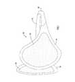
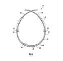
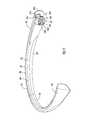
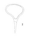
- FIG. 1is a perspective view of an ear warmer in an expanded configuration according to an embodiment of the invention.
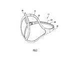
- FIG. 2is a front perspective view of the frame of the ear warmer illustrated in FIG. 1 .
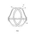
- FIG. 3is a front view of the frame of the ear warmer illustrated in FIG. 2 .
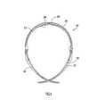
- FIG. 4is a rear view of the frame of the ear warmer illustrated in FIG. 2 .
- FIG. 5is a top view of the frame of the ear warmer illustrated in FIG. 2 .
- FIG. 6is a bottom view of the frame of the ear warmer illustrated in FIG. 2 .
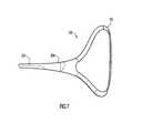
- FIG. 7is a right side view of the frame of the ear warmer illustrated in FIG. 2 .
- FIG. 8is left side view of the frame of the ear warmer illustrated in FIG. 2 .
- FIG. 9is a rear perspective view of the frame of the ear warmer illustrated in FIG. 2 .
- FIG. 10is a perspective view of the frame of the ear warmer illustrated in FIG. 2 in a collapsed configuration.
- FIG. 11is a top view of the frame of the ear warmer illustrated in FIG. 2 in a collapsed configuration.
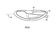
- FIG. 12is a side view of the frame of the ear warmer illustrated in FIG. 2 in a collapsed configuration.
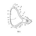
- FIG. 13is a perspective view of an ear portion of the frame of the ear warmer illustrated in FIG. 2 .
- FIG. 14is a top view of the ear portion illustrated in FIG. 13 .
- FIG. 14Ais a front perspective view of the ear portion illustrated in FIG. 13 .
- FIG. 15is a front view of the ear portion illustrated in FIG. 13 .
- FIG. 16is a rear view of the ear portion illustrated in FIG. 13 .
- FIG. 17is a perspective view of a band portion of the frame of the ear warmer illustrated in FIG. 2 .
- FIG. 18is a top view of the band portion illustrated in FIG. 17 .
- FIG. 19is a bottom view of the band portion illustrated in FIG. 17 .
- FIG. 20is a front view of the band portion illustrated in FIG. 17 .
- FIG. 21is a side view of the band portion illustrated in FIG. 17 .
- FIG. 21Ais a perspective view of an alternative embodiment of a band portion of a frame according to an embodiment of the invention.
- FIG. 21Bis a top view of an alternative embodiment of a band portion of a frame according to an embodiment of the invention.
- FIGS. 22-23are perspective views of frames according other embodiments of the invention.
- FIG. 24is a side view of an ear portion according to another embodiment of the invention.
- FIG. 25is a side view of an ear portion according to another embodiment of the invention.
- FIG. 26is a side view of a portion of an ear warmer according to an embodiment of the invention.
- FIGS. 26A and 26Bare partial cross-sectional views of an embodiment of a portion of an ear warmer according to an embodiment of the invention.
- FIGS. 27 and 28are a side view and cross-section view along line 28 - 28 , respectively, of a portion of an ear warmer having a press-fit connection, according to an embodiment of the invention.
- FIGS. 29 and 30are a side view and cross-section view along line 30 - 30 , respectively, of a portion of an ear warmer having a press-fit connection, according to another embodiment of the invention.
- FIGS. 31 and 32are a side view and cross-section view along line 32 - 32 , respectively, of a portion of an ear warmer having a tongue-and-groove connection, according to an embodiment of the invention.
- FIG. 33is a side view of a portion of an ear warmer having a clip-on connection, according to an embodiment of the invention.
- FIG. 34is a side view of a portion of an ear warmer having a fabric member, according to an embodiment of the invention.
- FIG. 35is a side view of a portion of an ear warmer having a fabric member, according to another embodiment of the invention.
- FIG. 36is a side view of a portion of an ear warmer having a fabric member, according to another embodiment of the invention.
- FIG. 37is a side view of a portion of the ear warmer having a fabric member, according to another embodiment of the invention.
- FIG. 38is a perspective assembly view of the portion of the ear warmer shown in FIG. 37 .
- FIG. 39is a perspective view of a portion of an ear warmer having a fabric member covering at least a portion of the inner side of the frame, according to an embodiment of the invention.
- FIG. 40is a perspective view a portion of an ear warmer having a fabric member covering at least a portion of the inner side of the frame, according to another embodiment of the invention.
- FIG. 41is a perspective view a portion of an ear warmer having a fabric member and a support member, according to another embodiment of the invention.
- FIG. 42is a perspective view of a frame of an ear warmer according to an embodiment of the invention.
- FIG. 43is a rear view of the frame illustrated in FIG. 42 .
- FIG. 44is a front view of the frame illustrated in FIG. 42 .
- FIG. 45is a right side view of the frame illustrated in FIG. 42 .
- FIG. 46is left side view of the frame illustrated in FIG. 42 .
- FIG. 47is a top view of the frame illustrated in FIG. 42 .
- FIG. 48is a bottom view of the frame illustrated in FIG. 42 .
- An ear warmercomprises a frame and a fabric member.
- the framehas an ear portion and a band portion.
- the ear portion of the frameincludes a first side and a second side opposite the first side.
- the first side of the ear portiondefines an interior portion of an opening.
- the second side of the ear portiondefines an exterior portion of the opening.
- the fabric memberincludes at least its own ear portion coupled to a portion of the frame.
- the ear portion of the fabric membercovers the interior portion of the opening in substantially its entirety.
- the ear portion of the fabric membercovers less than an entirety of the exterior portion of the opening.
- the term “less than an entirety”should be understood to mean that the fabric member covers some of the exterior portion of the opening or none of the exterior portion of the opening.
- FIG. 1An ear warmer 100 according to an embodiment of the invention is illustrated in FIG. 1 .
- the ear warmer 100includes a frame 110 and two fabric members 230 and 250 .
- the ear warmer 100is disposable in an expanded configuration and in a collapsed configuration.
- the frame 110 of the ear warmer 100includes a first ear portion 130 , a second ear portion 190 and a band portion 200 .
- fabric member 250is coupled to the first ear portion 130 .
- fabric member 230is coupled to the second ear portion 190 .
- the fabric members 230 and 250can be fixedly or removably coupled to the respective ear portions. Various techniques for coupling of the fabric members 230 and 250 are discussed below in detail.
- the frame 110can be a single piece of material in which the first ear portion 130 , the second ear portion 190 and the band portion 200 are formed monolithically (i.e., unitary construction).
- the band portion 200can be adjustable in length.
- the first ear portion 130 and the second ear portion 190can be fixedly coupled to the band portion 200 .
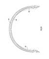
- FIG. 22An embodiment of a single-piece frame is illustrated in FIG. 22 .
- the frame 270includes a band portion 272 , a first ear portion 274 and a second ear portion 276 .
- the first ear portion 274 and the second ear portion 276are not collapsible with respect to the band portion 272 .
- the frame 270can have an expanded configuration corresponding to a position on the user's head and an unexpanded configuration corresponding to a position off the user's head.
- the frame 270can have an inward bias that defines the unexpanded configuration.
- FIG. 22shows the frame 270 in the expanded configuration.
- the position of ear portions 274 and 276 in the expanded and unexpanded configurationscan differ from that shown in FIG. 22 .
- FIG. 23An embodiment of an alternative frame is illustrated in FIG. 23 .
- the frame 280has unitary construction including a band portion 284 , a first ear portion 286 and a second ear portion 288 .
- the first ear portion 286has an end portion 287 that couples to the band portion 284 .
- the second ear portion 288has an end portion 289 that couples to the band portion 284 .
- the ends 287 and 289are wrapped around the band portion 284 .
- FIGS. 2 through 9illustrate the frame 110 of the ear warmer 100 in an expanded configuration.
- FIGS. 10 through 12illustrate the frame 110 of the ear warmer 100 in a collapsed configuration.
- the frame 110includes a band portion 200 , a first ear portion 130 coupled to the band portion 200 , and a second ear portion 190 coupled to the band portion 200 .
- the band portion 200is configured to extend around the back of a user's head.
- the band portion 200includes a middle portion 203 , a first end portion 202 , and a second end portion 204 .
- the band portion 200has an inner side 206 (the side that is disposed adjacent a user when the ear warmer is worn by the user), an outer side 208 (the side opposite the inner side and distal from a user when the ear warmer is worn by the user), an upper side 210 (the side that faces up when the ear warmer is worn by a user), and a lower side 212 (the side that faces down when the ear warmer is worn by a user).
- the band portion 200varies in a height dimension and has a substantially tapered shape (see FIG. 4 ). As illustrated in FIG. 4 , the middle portion 203 of the band portion 200 is of a lesser height or thickness than either of the first end portion 202 of the band portion 200 and the second end portion 204 of the band portion 200 . In an alternative embodiment, the band portion 200 has a constant height or thickness.
- the first end portion 202 of the band portion 200includes a first coupling portion 218 configured to be coupled to the first ear portion 130 of the frame 110 .
- the second end portion 204 of the band portion 200includes a second coupling portion 220 configured to be coupled to the second ear portion 190 of the frame 110 .
- the first coupling portion 218 and the second coupling portion 220are substantially similar in function and structure with the exception that they are reverse images of each other. Therefore, only the first coupling portion 218 of the band member 200 will be discussed in detail.
- the coupling portionsmay have different configurations and/or structures.
- the first coupling portion 218includes an end surface 214 of the band portion 200 and includes distal end 222 .
- the distal end 222 of the first coupling portion 218has a mounting structure and defines a planar surface (also referred to herein as the “oblique plane”).
- the mounting structureis cylindrical in shape, the mounting structure need not be cylindrical in shape.
- the coupling portion and mounting structuremay be of any shape, such as cubic or rectangular.
- the oblique planeis oblique to the surfaces defined by the upper side 210 and lower side 212 of the band portion 200 . Additionally, as illustrated in FIG. 19 , the oblique plane is oblique to the surfaces defined by the inner side 206 proximate the coupling portion 218 and the outer side 208 of the band portion 200 proximate the coupling portion 218 .
- the oblique planeenables the ear portion to move upwardly and inwardly to a collapsed configuration as described below.
- the end surface of the band portionis at an oblique plane with respect to only one side of the band portion.
- the end surface of the band portioncan be substantially perpendicular to the outer surface of the band portion.
- the frameincluding the band portion and the ear portions, is made of a single material.
- the frameis made of polypropylene.
- the frameis made of a thermoplastic resin material, such as Crastin® sold by DuPont, or Grillamid®.
- the band portion 200includes a recess 207 (see FIG. 17 ).
- the band portion 200is made of a first material 201 and a second material 219 (see FIG. 17 ).
- the second material 219may be any material that increases friction contact.
- the second material 219can be any material that can distribute the force of the ear warmer 100 when retained on the user.
- the second materialextends for less than the entire height of the band portion.
- the second materialcan be on the inside of the band portion only, the inside and outside of the band portion, or the outside of the band portion only.
- the second materialcan be disposed in two or more separate locations on the band portion.
- the second materialextends across an entire width of the band portion.
- the first material 201is a plastic material and the second material 219 is a rubber material.
- the band portion of the frameis illustrated as being elongated, the band portion need not be elongated in shape.
- the coupling portion 218is illustrated and described in detail.
- the coupling portions 218 and 220are substantially the same. Accordingly, only coupling portion 218 is described in detail. It is to be understood that alternative embodiments of the band portion to not necessarily need to have all of the features and/or structures discussed with respect to coupling portion 218 . In other words, alternative coupling portions can have any combination of the structures.
- the coupling portion 218includes a mounting structure 218 a that in substantially cylindrical in shape.
- the mounting structure 218 ahas a lower surface that can include one or more recesses or notches 218 d , the function of which is described later.
- the mounting structure 218 aalso includes a center shoulder 218 b that has an opening 218 c that is configured to receive a connector, such as a screw.
- the end of the band portion 200includes a first end surface 221 a and a second end surface 221 b that is proximate to surface 221 a .
- the surfaces 221 a and 221 bare offset and at an angle with respect to each other.
- the configuration of surfaces 221 a and 221 bassist with the movement of the ear portion with respect to the band portion.
- surfaces 221 a and 221 bare disposed in the same plane. As described below, surfaces 221 a and 221 b form contact surfaces that limit the rotation of the ear portion relative to the band.
- the end of the band portion 200also includes another surface 221 a and a shoulder 221 d adjacent surface 221 c .
- the surface 221 c and shoulder 221 dform an abutment that is contacted by the ear portion to limit the rotation of the ear portion with respect to the band portion 200 .
- the band portiondoes not include a surface and shoulder as previously described.
- the band portionincludes a coupler that is configured to removably couple a label, such as a brand label, to the band portion.
- the coupleris disposed at the rear of the band portion. In alternative embodiments, the coupler is disposed on a side of the band portion, for example near the portion of the band, which couples to the ear portion, or at any other location on the band portion.
- FIGS. 21A and 21BAn alternative embodiment of the band portion is illustrated in FIGS. 21A and 21B .
- a band portion 200 ′includes support members 202 ′ disposed on the inner surface 204 ′ of the band portion 200 ′.
- Support members 202 ′are configured to provide added strength and support to the band portion 200 ′.
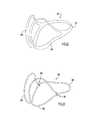
- FIGS. 13-16An embodiment of an ear portion is illustrated in FIGS. 13-16 .
- the first ear portion 130 of the frame 110 and the second ear portion 190 of the frame 110are substantially similar in function and structure. Therefore, only the first ear portion 130 is discussed in detail.
- the first ear portion 130 of the frame 110defines an opening 134 and a center point 152 .
- the first ear portion 130includes a proximal end portion 156 , which includes a proximal end point 136 (the portion and point being proximate to the coupling of the first ear portion 130 and the band portion 200 ); a distal end portion 158 , which includes a distal end point 138 (the portion and point being distal from the coupling of the first end portion 130 and the band portion 200 ); an uppermost portion 160 , which includes an uppermost point 140 (the portion and point being uppermost when the ear warmer is disposed in an expanded configuration on a user); and a lowermost portion 162 , which includes a lowermost point 142 (the portion and point being lowermost when the ear warmer is disposed in an expanded configuration on a user).
- first ear portion 130has been identified as being proximal, distal, uppermost, and lowermost, it should be understood that there may be, for example, several uppermost points of the first ear portion. In such a case, the “uppermost point” includes the several points. The same is true for the proximal, distal, and lowermost points. In addition, the terms proximal, distal, uppermost, and lowermost are used for convenient reference with respect to the orientation shown in FIGS. 2 through 9 and 13 through 16 . It should be understood that these locations of the frame are still applicable regardless of the orientation of the frame at any given time.
- a portion 137 of the first ear portion 130 of the frame 110is disposed between the proximal end point 136 and the uppermost point 140 and has a first part 137 ′ and a second part 137 ′′. From a side view of the first ear portion 130 (see FIG. 13 ), the first part 137 ′ of the portion 137 has a convex configuration with respect to the center point 152 . Similarly, a portion 143 of the first ear portion 130 of the frame 110 is disposed between the lowermost point 142 and the proximal end point 136 . The portion 143 has a first part 143 ′ and a second part 143 ′′.
- the first part 143 ′ of the portion 143has a convex configuration with respect to the center point 152 .
- at least a portion of each of the portions 137 and 143 of the first ear portion 130bend or curve away from the center point 152 .
- the location and number of inflection points in portions 137 and 143can vary along the ear portion.
- the portion 139 of the first ear portion 130 of the frame 110 that is disposed between the uppermost point 140 and the distal end point 138has a concave configuration with respect to the center point 152 .
- the portion 141 of the first ear portion 130 of the frame 110 that is disposed between the distal end point 138 and the lowermost point 142has a concave configuration with respect to the center point 152 .
- at least a portion of each of the portions 139 and 141 of the first ear portion 130bend toward the center point 152 .
- one or both of the portions 139 and 141can include a concave portion or section and a convex portion or section, relative to the center point.
- the first ear portion 130includes an inner side 144 (the side that is disposed adjacent a user when the ear warmer is worn by the user), an outer side 146 (the side opposite the inner side and distal from a user when the ear warmer is worn by the user), an upper side 148 (the side that faces up when the ear warmer is worn by a user), and a lower side 150 (see FIG. 13 ) (the side that faces down when the ear warmer is worn by a user).
- the inner side 144 of the first ear portion 130defines an interior portion or region of the opening 134 .
- the outer side 146 of the first ear portion 130defines an exterior portion or region of the opening 134 .
- the inner side 144 of the first ear portion 130 of the frame 110has an innermost surface 154 .
- the innermost surface 154is the portion of the inner side 144 of the first ear portion 130 directly adjacent a user's head when the ear warmer 100 is worn by the user.
- a top view of a two-dimensional projection of the innermost surface 154is a curved line that curves around a point A, which is disposed on the inner side of the first ear portion 130 .
- the first ear portion 130is curved such the distal end portion 158 is configured to be disposed closer to a user's head, or to place more pressure on the user's head (if the entire portion of the frame is contacting the user's head), than a mid-point of the innermost surface 154 when the ear warmer 100 is worn by the user.
- the frame 110is configured to apply lateral forces to the user's head inwardly where the forces are greatest at the distal end portion 158 .
- the distal end portion 158 of the frame 110is flexible.
- the lateral force of the distal end portion 158 against a user's headcauses the distal end portion to bend or flex and, thus, to better fit along the user's head.
- the first ear portionis curved such that the distal end portion of the first ear portion is configured to be disposed closer to a user's head than the proximal end portion of the first ear portion when the ear warmer is worn by the user.
- the portion of the innermost surface disposed between the proximal end portion and the distal end portiondoes not have a curved shape.
- a two-dimensional projection of a front view of the innermost surface 154is a curved line that has three radii of curvature. Specifically, the two-dimensional projection has a first part that bends or curves around point B, a second part that bends or curves around part C, and a third part that bends or curves around point D.
- the distal end portion 138is curved such that a center portion of the distal end portion 138 is configured to be disposed closer to a user's head than the remaining portions of the distal end portion 138 when the ear warmer is worn by a user.
- the uppermost portionis configured to be disposed closer to the user's head than the lowermost portion when the ear warmer is worn by the user.
- the first ear portionis curved such that the lowermost portion is configured to be disposed closer to the user's head than the uppermost portion when the ear warmer is worn by the user.
- the first ear portion 130is described and illustrated as having a particular shape, in other embodiments, the first ear portion has different shapes. Additionally, in one embodiment, the first ear portion is made of a plastic material. In an alternative embodiment, the first ear portion is made of another material, such as a metal.
- the first ear portion 130has an abutting and complimentary fit with the band portion 200 . More specifically, returning to FIG. 13 , the first ear portion 130 includes coupling portion 164 that extends from an end surface 166 of the first ear portion 130 .
- the coupling portion 164includes a distal end 165 that defines a surface 165 a .
- the surface 165 aincludes one or more ridges or protrusions 165 b that engage the recesses 218 d as the ear portion rotates.
- the coupling portion 164is received in structure 218 a .
- the end portion of the first ear portion 130includes surfaces 167 a and 167 b that compliment and engage surfaces 221 a and 221 b on the band portion 200 when the ear portion 130 is in its collapsed configuration.
- the end portionalso includes a protrusion 167 c with a contact surface 167 d that engages the surface 221 c and shoulder 221 d to form a secondary stop to limit the rotation of the ear portion.
- the ear portiondoes not include protrusion 167 c and band portion 200 does not include the surface 221 c and shoulder 221 d . As illustrated in FIG.
- the surface defined by the distal end 222 of the coupling portion 218 of the band portion 200abuts the surface defined by the distal end 165 of the coupling portion 164 .
- the end surface 214 of the band portion 200 of the frame 110abuts the end surface 166 of the first end portion 130 .
- the band portion 200abuts the first ear portion 130 and has surfaces, including the surface defined by the distal end 222 of the coupling portion 218 and the end surface 214 of the band portion 200 , that fit complimentary to surfaces of the first end portion 130 , including the surface defined by the distal end 165 of the coupling portion 164 and the end surface 166 of the first ear portion 130 , when the first ear portion 130 is in its collapsed configuration.
- the transition between the outer surface 208 of the band portion 200 and the outer surface 146 of the first ear portion 130is a smooth transition or a substantially smooth transition.
- the outer surface 208 of the band portion 200 and the outer surface 146 of the first ear portion 130form a substantially continuous surface when the ear warmer is in the expanded configuration.
- the sameis true for the remaining surfaces of the band portion 200 and the first ear portion 130 .
- the upper surface 210 of the band portion 200 and the upper surface 148 of the first ear portion 130form a substantially continuous surface.
- the lower surface 212 of the band portion 200 and the lower surface 150 of the first ear portion 130form a substantially continuous surface.
- the coupling portions of the ear portion and the band portionis located on the inner surface.
- the inner surface of the ear portion and the inner surface of the band portionform a substantially continuous surface.
- the coupling portions of the band portion and the ear portionare located at different locations.
- the substantially continuous surface formed by the upper surface 210 of the band portion 200 and the upper surface 148 of the first ear portion 130extends from the first ear portion 130 to the second ear portion 190 .
- the substantially continuous surfaces formed by the lower, upper, and inner surfaces of the band portion 210 and the first ear portion 130also extend to the respective surfaces of the second ear portion.
- the upper surface of the ear warmer 100 , the lower surface of the ear warmer 100 , and the outer surface of the ear warmer 100collectively form a smooth contour.
- any combination of the corresponding surface, outer surface, upper surface and lower surface of any of the frame componentscan form a substantially continuous surface.
- a screw(not illustrated) is used to pivotally couple the first ear portion 130 to the band portion 210 .
- a first end of the screwextends from the inner side 144 of the first ear portion 130 and a second end of the screw is disposed within the band portion 200 and is not outwardly visible. In other words, only a single end of the screw is exposed (i.e., disposed outside of the frame 110 of the ear warmer 100 ).
- a rivet, a pin, a brad, or any other coupling deviceis used to pivotally couple the ear portions 130 and 190 to the band portion 200 .
- FIGS. 10 though 12illustrate the frame 110 of the ear warmer 100 in a collapsed configuration.
- the first ear portion 130 and the second ear portion 190are disposed adjacent to and substantially within the same plane 195 as the band portion 200 when the frame 110 is in its collapsed configuration.
- the coupling arrangement between the band portion 200 and the ear portionsallow the ear portions 130 and 190 to pivot into and out of the collapsed configuration.
- the ear warmer 100has a low profile when in its collapsed configuration.
- the oblique plane defined by the band portion 200allows the ear portion 130 and 190 to move in a way that contributes to this overall low profile.
- the oblique planeallows the ear portions to rotate about the pivot connection while being substantially within or proximate the same plane as the band portion 200 .
- Ear warmer 100is configured to allow a predetermined range of motion between the expanded configuration and the collapsed configuration.
- this range of motiondoes not include movement from the expanded configuration to a different collapsed configuration, for example, where the ear portions of the frame are disposed on a side of the band opposite from their position in the collapsed configuration within the range of motion.
- two different mechanismseach produce a respective stop that defines a respective end point of the range of motion (as discussed below).
- the ear portionscan rotate continuously and are not limited to a particular range.
- the ear portionscan be slidably coupled to the band portion, or can rotate about another axis than that described above.
- the frames 270 and 280are of a unitary or monolithic structure.
- the band portions 272 and 286do not have adjustable lengths.
- the band portionis an adjustable band.
- the band portion of the frameincludes several different and separate items.
- the ear portionsmay be formed of a first material and a second material that is different than the first material.
- the ear portions 290 and 291are made of a first material 292 and a second material 294 .
- the first material 292may be any type of plastic and the second material 294 may be any type of resilient material, such as rubber.
- the resilient material 294provides for an increased gripping surface for contact with the user or other article.
- the resilient material 294also increases the distribution of the application of clamping or gripping force of the ear warmer on the user's head.
- the second materialextends an entire width of a portion of the ear portion 290
- the second materialonly extends across a portion of width of a portion of the ear portion 292 .
- the recess or opening in the ear portion in which the second material is disposedcan have any size or configuration.
- the location of the recess or opening for the second materialcan vary along the ear portion.
- the band portion of an ear warmercan also include a portion of a first material and a portion of a second material that is different from the first material.
- the ear warmer 100includes fabric members 230 and 250 .
- the fabric members 230 and 250are coupled to the frame 110 of the ear warmer 100 .
- the fabric members 230 and 250are configured to substantially cover at least a portion of the ear portions 130 and 190 of the ear warmer 100 .
- Various configurations of the fabric membersare described below.
- FIG. 26shows a side view of a portion of an ear warmer according to an embodiment of the invention.
- the frame 310includes an ear portion 330 .
- a fabric member 350is fixedly coupled to the ear portion 330 of the frame 310 .
- the fabric member 350can be fixedly coupled to the ear portion 330 of the frame 310 by any technique or method, including radio frequency (RF) welding, ultrasonic welding, or an adhesive such as glue.
- RFradio frequency
- the perimeter portion 352 of the fabric member 350can be fixedly coupled to or proximate to the perimeter portion 332 of the ear portion 330 of the frame 310 .
- peripheral portionis intended herein to include the perimeter or a portion offset from and proximate to the perimeter of a membrane, member or portion.
- a weld, adhesive or connectorcan be located along the actual perimeter of the fabric member 350 and a portion of the ear portion 330 of the frame 310 offset from and proximate to the perimeter of the ear portion 330 .
- the fabric memberincludes binding coupled along at least a portion of the perimeter of the fabric member.
- the bindingcan be coupled to the frame using the techniques identified above.
- the fabric membercan be coupled to the frame.
- the bindingprovides additional support and cushioning to the user. Additionally, the binding provides a seal between the ear warmer and a user's head.
- the frame 6000such as an ear portion, includes a fabric member 6050 coupled thereto.
- fabric member 6050includes a binding 6100 coupled thereto in any conventional manner.
- the binding 6100can be stitched or sewn to the fabric member 6050 by seam 6200 .
- Fabric member 6050can be coupled to the frame member 6000 using any conventional technique, including an adhesive, welding, such as RF or ultrasonic welding, or the like.
- the binding 6100is configured so that a portion of it is disposed adjacent to the innermost surface of the frame member 6000 .
- the binding 6100provides added cushioning, which provides a more comfortable fit.
- the binding 6100also provides a better seal against a user's head to improve temperature control by preventing external air from entering any space between the ear portion and the user's head.
- the bindingcan be replaced by another piece of fabric material, a piece of foam, or any other structure that would assist with the cushioning and sealing functions above.
- FIGS. 27 through 32show examples of a fabric member that can be removably coupled to the ear portion of the frame. Although these figures show the fabric member being removably coupled to the ear portion of frame via press-fit connections, tongue-and-groove connections, clip-on connections and slide-and-lock connections, other types of the removable connections are also possible. In other words, FIGS. 27 through 32 merely provide examples of removable connections and other types of removable connections are possible.
- FIGS. 27 and 28show a side view and cross-section view along line 28 - 28 in FIG. 27 , respectively, of a portion of an ear warmer 400 having a press-fit connection, according to an embodiment of the invention.
- Ear warmer 400includes a frame 410 that has an ear portion 430 .
- the fabric member 450can be fixedly coupled to an attachment member 460 along a portion of the perimeter of the fabric member 450 .
- the attachment member 460can be made of, for example, plastic defining an opening 462 along its length and directed inwardly. As shown in FIG.
- the opening 462is configured such that the attachment member 460 forms a press fit over a portion of the perimeter 432 of the ear portion 430 of the frame 410 .
- This configurationallows the fabric member 450 to be removably attached to the ear portion 430 of the frame 410 .
- the fabric member 450can be made from an elastic material that is stretched when the fabric member 450 and attachment member 460 are coupled onto the ear portion 430 of the frame 410 .
- the fabric member 450can be larger than the ear portion 430 of the frame 410 so that the fabric member 450 can extend over the perimeter 432 of the ear portion 430 of the frame 410 when being configured onto the ear portion 430 of the frame 410 .
- FIGS. 29 and 30show a side view and cross-section view along line 30 - 30 in FIG. 29 , respectively, of a portion of an ear warmer 500 having a press-fit connection, according to another embodiment of the invention.
- the ear warmer 500includes a frame 510 that has an ear portion 530 .
- the fabric member 550can be fixedly coupled to an attachment member 560 along a portion of the perimeter of the fabric member 550 . In this embodiment, however, the opening 562 defined by the attachment member 560 along its length is directed outwardly. As shown in FIG.
- the opening 562has a size such that the attachment member 560 forms a press fit along a portion of the ear portion 530 of the frame 510 .
- the ear portion 530 of the frame 510defines an interior region defined by a perimeter.
- the attachment member 560removably attaches the fabric member 550 to a portion of this perimeter of the interior region.
- the attachment member 560has sufficient strength and rigidity so that the attachment member 560 is inserted or “popped” into an opening defined in the ear portion 530 .
- FIGS. 31 and 32show a side view and cross-section view along line 32 - 32 in FIG. 31 , respectively, of a portion of an ear warmer 600 having a tongue-and-groove connection, according to an embodiment of the invention.
- the ear warmer 600includes a frame 610 that has an ear portion 630 .
- the fabric member 650can be coupled (e.g., fixedly coupled) to an attachment member 660 along a portion of the perimeter of the fabric member 650 .
- the attachment member 660has a surface with a groove structure formed therein, and complimentary fits onto or receives the tongue-like portion 632 of the ear portion 630 of the frame 610 .
- the tongue-like portion 632 of the ear portion 630 of the frame 610can be monolithically formed with the remaining portions of the ear portion 630 of the frame 610 .
- a tongue-like membercan be coupled (e.g., fixedly coupled) to the ear portion of the frame by welding or an adhesive.
- the tongue-like structurecan be coupled (e.g., fixedly coupled) to the fabric member and the groove-like structure can be disposed on the ear portion or the frame, for example, either fixedly coupled to or monolithically formed with the ear portion of the frame.
- FIG. 33shows a side view of a portion of an ear warmer 700 having a clip-on connection, according to an embodiment of the invention.
- the ear warmer 700includes a frame 710 that has an ear portion 730 with a perimeter 732 .
- a fabric member 750can be coupled (e.g., fixedly coupled) to one or more attachment members 760 along various positions of the perimeter of the fabric member 750 .
- FIG. 33shows three attachment members 760 although in other embodiments, one, two, four or more than four attachment members are possible.
- the various attachment memberscan be formed integrally or can be coupled together by different structures.
- attachment members 760can be made of any material that allows the attachment members 760 to coupled to the frame, including, for example, plastic or metal.
- the opening 762 of each attachment member 760is configured such that it forms a complimentary fit over a portion of the perimeter 732 of the ear portion 730 of the frame 710 .
- This mating arrangement of the attachment members 760 and the ear portion 730allows the fabric member 750 to be removably attached to the ear portion 730 of the frame 710 . Similar to the embodiment described above in reference to FIGS.
- the fabric member 750can be made from an elastic material that is stretched when the fabric member 750 and attachment members 760 are coupled onto the ear portion 730 of the frame 710 .
- the fabric member 750can be larger than the ear portion 730 of the frame 710 so that the fabric member 750 can extend over the perimeter 732 of the ear portion 730 of the frame 710 when being coupled onto the ear portion 730 of the frame 710 .
- FIGS. 34 through 38show examples of a fabric member removably coupled to the ear portion of the frame by covering substantially an entirety of the opening on the inner side of the ear portion of the frame and less than an entirety of the opening on the outer side of the ear portion of the frame.
- the ear portion of the frametypically defines an opening through which sound can pass.
- This openinghas an interior portion corresponding to the inner side of the ear portion of the frame and an exterior portion corresponding to the outer side of the ear portion of the frame.
- an ear portion of the fabric membercan be configured such that it covers the interior portion of the opening substantially in its entirety and covers the exterior portion of the opening in less than its entirety. Covering the interior portion of the opening “substantially in its entirety” is intended to describe embodiments where the entire interior portion of the opening is covered except for minor exceptions such as, for example, small vents.
- FIG. 34shows a side view of a portion of an ear warmer 800 having a fabric member 850 , according to an embodiment of the invention.
- the ear warmer 800includes a frame 810 that has an ear portion 830 .
- the fabric member 850includes an ear portion with a heat-retaining fabric 852 on the inner side.
- the ear warmer 800can include an elastic fabric or member 854 on the outer side.
- the elastic fabric 854is coupled (e.g., fixedly coupled) to the heat-retaining fabric 852 at three locations.
- the elastic or rubber fabriccan be coupled to the heat-retaining fabric 852 at any number of locations.
- the elastic member 854can be a clip or snap-on structure that clips or clamps the heat-retaining fabric 852 to the ear portion 830 .
- the elastic member 854can be a separate piece that can wrap around the inner side and the outer side of a portion of the ear portion 830 and couple the fabric 852 thereto.
- the heat-retaining fabric 852 and the elastic fabric 854are coupled together in a manner other than fixedly coupled, such as removably coupled.
- the fabric member 850can be removably coupled to the ear portion 830 of the frame 810 by stretching the elastic fabric on the outer side of the fabric member 850 so that it can move over the distal end of the ear portion 830 of the frame 810 .
- the heat-retaining fabric 852 on the inner side of the fabric member 850covers the interior portion of the opening of the ear portion 830 of the frame 810 substantially in its entirety while the elastic fabric 854 covers the exterior portion of the opening of the ear portion 830 of the frame 810 in less than its entirety. Any combination of coupling techniques can be used to couple the fabric member 850 to the ear portion 830 .
- FIG. 35shows a side view of a portion of an ear warmer 900 having a fabric member 950 , according to another embodiment of the invention.
- the ear portion of the fabric member 950has a heat-retaining fabric 952 on the inner side, and an elastic fabric portion 954 and a heat-retaining portion 956 on the outer side.
- the elastic fabriccan be, for example, a rubber material or a heat-retaining fabric.
- the outer side of the fabric member 950is coupled (e.g., fixedly coupled) to the heat-retaining fabric 952 on the inner side along a portion of the perimeter.
- the fabric member 950can be removably coupled to the ear portion 930 of the frame 910 by stretching the elastic fabric 954 on the outer side of the fabric member 950 so that it can move over the distal end 932 of the ear portion 930 of the frame 910 .
- the fabric 952 and the heat-retaining portion 956can be formed integrally.
- FIG. 36shows a side view of a portion of an ear warmer 1000 having a fabric member 1050 , according to another embodiment of the invention.
- Fabric member 1050is coupled in a similar manner as fabric member 850 described above.
- the ear portion of the fabric member 1050has a heat-retaining fabric 1052 and an elastic fabric 1054 .
- the elastic fabriccan be, for example, a rubber material or a heat-retaining fabric.
- the elastic fabric 1054 on the outer sideis coupled (e.g., fixedly coupled) to the heat-retaining fabric 1032 on the inner side at two locations.
- the fabric member 1050can be removably coupled to the ear portion 1030 of the frame 1010 by stretching the elastic fabric 1054 on the outer side of the fabric member 1050 so that it can move over the distal end 1032 of the ear portion 1030 of the frame 1010 .
- FIG. 37shows a side view of a portion of the ear warmer 1100 having a fabric member 1150 , according to another embodiment of the invention.
- FIG. 38shows a perspective assembly view of the portion of the ear warmer 1100 shown in FIG. 37 .
- the fabric member 1150(one is shown in FIG. 37 for one ear portion of the frame) has an inner side and an outer side.
- the inner side 1152 of the fabric member 1150includes a coupling portion 1154 embodied as a button hole.
- the ear portion 1130 of the frame 1110includes a coupling portion 1132 embodied as a button and post.
- the coupling portion 1154 of the fabric member 1150is configured to mate with the coupling portion 1132 of the ear portion 1130 of the frame 1110 such that the fabric member 1150 is removably coupled to the ear portion 1130 of the frame 1110 .
- the coupling portion 1132 of the frame 1110is disposed on the inner side of the frame.
- the inner side and outer side of the fabric member 1150form a receptacle 1156 into which the distal end 1134 of the ear portion 1130 of the frame 1110 can be removably disposed.
- This side of the ear portion of the fabric member 1150is referred to herein as the distal end.
- the proximate end of the fabric member 1150is also removably coupled to the ear portion 1130 of the frame 1110 , as discussed above, by the coupling portion 1154 of the fabric member 1150 fitting into the coupling portion 1132 of the ear portion 1130 of the frame 1110 .
- the overall fabric member 1150can be coupled to the ear portion 1130 of the frame 1110 by coupling the distal end of the fabric member 1150 to the distal end 1134 of the ear portion 1130 of the frame 1110 , and then coupling the proximate end of the fabric member 1150 to the proximate end of the ear portion 1130 of the frame 1110 .
- the fabric member 1150can be removed from the frame 1110 by the reverse process.
- the coupling portion 1132 of the ear portion 1130 of the frame 1110is shown in FIGS. 37 and 38 as protruding from the inner side of the frame, in alternative embodiments, the coupling portion of the frame extends from a recess in the inner side of the frame.
- the distal end of the coupling portion of the framecorresponds to the remaining inner surface of the ear portion of the frame in that region and in general they form a smooth surface having the recess.
- the coupling portion of the ear portion of the frame and the coupling portion of the ear portion of the fabric membercan be disposed on any part of the frame, including the outer side of the frame.
- the outer side of the ear portion of the frameis substantially covered in its entirety and the inner side of the ear portion of the frame covered in less than its entirety.
- the ear portion of the frame and the ear portion of the fabric membercan be coupled together using any conventional technique, such as hook-and-loop fasteners, snap-fit connections, and button-and-hole arrangements having the hole on the frame.
- FIGS. 39 and 40show examples of a fabric member removably coupled to the frame by covering substantially an entirety of the inner side of the frame and less than an entirety of the opening on the outer side of each ear portion of the frame. More specifically, the examples shown in FIGS. 39 and 40 show a fabric member that substantially covers the entirety of the inner side of the frame including its ear portions and band portion while covering less than the entirety of the outer side of the frame.
- FIG. 39shows a perspective view of a portion of an ear warmer 1200 having a fabric member 1250 covering the inner side of the frame 1210 , according to an embodiment of the invention.
- the fabric member 1250has an inner-side portion 1252 and an outer-side portion 1254 .
- the inner-side portion 1252 of the fabric member 1250corresponds to both ear portions 1230 of the frame 1210 (of which only one is shown in FIG. 39 ) and the band portion 1270 of the frame 1210 (only a portion of which is shown in FIG. 39 ).
- the outer-side portion 1254 of the fabric member 1250can be extended over the distal end of the ear portions 1230 of the frame 1210 .
- the distal end of the ear portions 1230 of the frame 1210can be retained in a receptacle 1256 formed by the inner-side portion 1252 and the outer-side portion 1254 of the fabric member 1230 .
- the outer-side portion 1252 of the fabric member 1250can be made of, for example, an elastic fabric that allows the fabric member 1250 to be stretched over the distal end of the ear portions 1230 of the frame 1210 to insert and remove the frame 1210 from the fabric member 1250 .
- the fabric memberscan be bound, sewn, welded, coupled inside out, or monolithically formed (i.e., unitary construction).
- FIG. 40shows a perspective view a portion of an ear warmer 1300 having a fabric member 1350 covering the inner side of the frame 1310 , according to another embodiment of the invention.
- the fabric member 1350has only an inner-side portion.
- the inner-side portion of the fabric member 1350corresponds to both ear portions 1330 of the frame 1310 (of which only one is shown in FIG. 40 ) and the band portion 1370 of the frame 1310 (only a portion of which is shown in FIG. 40 ).
- the inner-side portion of the fabric member 1350can be fixedly coupled to the frame 1310 as described above in reference to FIG. 26 , or can be removably coupled to the frame, for example, as described above in reference to FIGS. 31 and 32 .
- the fabric membercan cover substantially the entirety of the inner side of the frame while being removably coupled to the frame as described above, for example, in reference to FIGS. 27 through 30 , 33 and 38 .
- the fabric membercan have a first portion that covers one of the ear portions of the frame and a second portion that covers the other of the ear portions of the frame.
- the first portion of the fabric membercan be coupled to the second portion of the fabric member via any type of coupling device, such as hook and loop configuration.
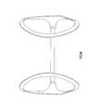
- FIG. 41shows a perspective view a portion of an ear warmer 1400 having a fabric member 1450 and a contact member 1470 , according to another embodiment of the invention.
- the frame 1410includes a contact member 1470 disposed on the inner side 1432 of the ear portion 1430 of the frame 1410 .
- the contact member 1470is configured to provide support and comfort to the user of the ear warmer 1400 by contacting the portion of the user's head behind the user's ears. Additionally, the contact member 1470 provides a seal between the ambient conditions and the user's ear. In other words, the contact member fills the gap between the frame 1410 of the ear warmer 1400 and the user's head.
- the contact member 1470extends along a portion of the inner side 1432 of the ear portion 1430 . In alternative embodiments, the contact member extends along substantially the entire inner side of the ear portion.
- the fabric memberincludes a receptacle that receives the contact member.
- the contact memberis otherwise coupled to the fabric member, such as via an adhesive.
- the contact memberis coupled to another portion of the ear warmer, such as the band portion of the frame.
- the contact membercan be made of a pre-formed foam or rubber material that is covered in fabric.
- the contactcan be slightly deformed and inserted into the opening of the ear portion. The contact member is then released and retained via the opening.
- the contact memberis a foam material or rubber material that is not covered in fabric.
- the contact memberis made of a material other than foam.
- the contact memberis a foam material that is covered with a material other than fabric.
- the fabric memberis generally described above as being disposed on the inner side of the ear portion of the frame, the fabric member can instead be disposed on the outer side of the ear frame. In some such embodiments, the fabric member can cover substantially an entirety of the opening on the outer side of the ear portion of the frame and less than an entirety of the opening on the inner side of the ear portion of the frame.
Landscapes
- Health & Medical Sciences (AREA)
- Life Sciences & Earth Sciences (AREA)
- Biomedical Technology (AREA)
- Acoustics & Sound (AREA)
- Biophysics (AREA)
- Otolaryngology (AREA)
- Psychology (AREA)
- Engineering & Computer Science (AREA)
- Physics & Mathematics (AREA)
- Heart & Thoracic Surgery (AREA)
- Vascular Medicine (AREA)
- Animal Behavior & Ethology (AREA)
- General Health & Medical Sciences (AREA)
- Public Health (AREA)
- Veterinary Medicine (AREA)
- Thermotherapy And Cooling Therapy Devices (AREA)
Abstract
Description
Claims (22)
Priority Applications (1)
| Application Number | Priority Date | Filing Date | Title |
|---|---|---|---|
| US12/168,027US9066829B2 (en) | 2003-08-12 | 2008-07-03 | Ear warmer with fabric member |
Applications Claiming Priority (4)
| Application Number | Priority Date | Filing Date | Title |
|---|---|---|---|
| US10/638,476US7650649B2 (en) | 2003-08-12 | 2003-08-12 | Ear warmer having an external frame |
| US11/688,712US8325961B2 (en) | 2003-08-12 | 2007-03-20 | Ear warmer with a speaker system |
| US11/754,327US20080141439A1 (en) | 2003-08-12 | 2007-05-28 | Ear Warmer Having A Membrane Forming A Receptacle |
| US12/168,027US9066829B2 (en) | 2003-08-12 | 2008-07-03 | Ear warmer with fabric member |
Related Parent Applications (1)
| Application Number | Title | Priority Date | Filing Date |
|---|---|---|---|
| US10/638,476DivisionUS7650649B2 (en) | 2003-08-12 | 2003-08-12 | Ear warmer having an external frame |
Publications (2)
| Publication Number | Publication Date |
|---|---|
| US20080307565A1 US20080307565A1 (en) | 2008-12-18 |
| US9066829B2true US9066829B2 (en) | 2015-06-30 |
Family
ID=34135675
Family Applications (5)
| Application Number | Title | Priority Date | Filing Date |
|---|---|---|---|
| US10/638,476Expired - Fee RelatedUS7650649B2 (en) | 2003-08-12 | 2003-08-12 | Ear warmer having an external frame |
| US12/168,027Expired - Fee RelatedUS9066829B2 (en) | 2003-08-12 | 2008-07-03 | Ear warmer with fabric member |
| US12/168,001Expired - Fee RelatedUS9259355B2 (en) | 2003-08-12 | 2008-07-03 | Ear warmer with fabric member |
| US12/168,015Active2029-01-15US10111781B2 (en) | 2003-08-12 | 2008-07-03 | Ear warmer with a substantially continuous surface |
| US16/173,803AbandonedUS20200008979A1 (en) | 2003-08-12 | 2018-10-29 | Ear warmer with a substantially continuous surface |
Family Applications Before (1)
| Application Number | Title | Priority Date | Filing Date |
|---|---|---|---|
| US10/638,476Expired - Fee RelatedUS7650649B2 (en) | 2003-08-12 | 2003-08-12 | Ear warmer having an external frame |
Family Applications After (3)
| Application Number | Title | Priority Date | Filing Date |
|---|---|---|---|
| US12/168,001Expired - Fee RelatedUS9259355B2 (en) | 2003-08-12 | 2008-07-03 | Ear warmer with fabric member |
| US12/168,015Active2029-01-15US10111781B2 (en) | 2003-08-12 | 2008-07-03 | Ear warmer with a substantially continuous surface |
| US16/173,803AbandonedUS20200008979A1 (en) | 2003-08-12 | 2018-10-29 | Ear warmer with a substantially continuous surface |
Country Status (1)
| Country | Link |
|---|---|
| US (5) | US7650649B2 (en) |
Cited By (1)
| Publication number | Priority date | Publication date | Assignee | Title |
|---|---|---|---|---|
| US12108823B1 (en)* | 2024-03-19 | 2024-10-08 | Larry Milder | Ear muffs for hats |
Families Citing this family (23)
| Publication number | Priority date | Publication date | Assignee | Title |
|---|---|---|---|---|
| US6332223B1 (en) | 2000-04-05 | 2001-12-25 | Gray Matter Holdings, Llc | Apparatus and method for making an ear warmer having interior seams |
| EP1345552A4 (en) | 2000-12-29 | 2004-11-03 | 180S Inc | Ear protection device |
| US6735784B2 (en)* | 2002-01-28 | 2004-05-18 | 180S, Inc. | Apparatus and method for making an ear warmer and an ear warmer frame |
| KR100453060B1 (en)* | 2002-11-15 | 2004-10-15 | 삼성전자주식회사 | Methods for fixing-up lastURL representing path name and file name of asset in MPV environment |
| US7650649B2 (en)* | 2003-08-12 | 2010-01-26 | 180S, Inc. | Ear warmer having an external frame |
| US7212645B2 (en)* | 2003-08-12 | 2007-05-01 | 180S, Inc. | Ear warmer with a speaker system |
| US7222373B2 (en)* | 2003-08-12 | 2007-05-29 | 180S, Inc. | Ear warmer having a membrane forming a receptacle |
| CA105900S (en) | 2003-08-12 | 2006-10-19 | 180S Inc | Frame for ear warmer |
| US7962970B2 (en)* | 2003-08-12 | 2011-06-21 | 180S, Inc. | Ear warmer having a curved ear portion |
| US7735154B2 (en)* | 2004-06-15 | 2010-06-15 | Gordini Usa Inc. | Protective ear appliance |
| JP4112608B2 (en)* | 2006-03-17 | 2008-07-02 | 太陽メディカル株式会社 | Head jewelry |
| WO2008091909A2 (en)* | 2007-01-22 | 2008-07-31 | 180S, Inc. | Ear protection device |
| WO2009009730A1 (en)* | 2007-07-11 | 2009-01-15 | 180S, Inc. | Accessory with light source |
| US8443467B2 (en)* | 2008-02-15 | 2013-05-21 | Sound Team Enterprise Co., Ltd. | Earmuff assembly |
| US9301039B2 (en)* | 2010-01-04 | 2016-03-29 | Apple Inc. | Headphone |
| USD643578S1 (en)* | 2010-03-09 | 2011-08-16 | Ryano-Guard, LLC | Protective headgear device |
| US20110219518A1 (en)* | 2010-03-15 | 2011-09-15 | Shayna Leigh Schlickman | Earmuffs and Designer Headband Combination |
| US9276539B2 (en) | 2013-02-06 | 2016-03-01 | Zeikos Inc. | Power transferring headphones |
| USD722996S1 (en)* | 2013-11-21 | 2015-02-24 | Zeikos Inc. | Headphones |
| US9271063B2 (en) | 2013-02-06 | 2016-02-23 | Zeikos Inc. | Power transferring headphones |
| US9774943B1 (en)* | 2016-01-15 | 2017-09-26 | Bplugz, Llc | Ear bud stabilizer |
| USD796474S1 (en)* | 2016-03-07 | 2017-09-05 | Apple Inc. | Headphones |
| USD974324S1 (en)* | 2019-12-20 | 2023-01-03 | Hewlett-Packard Development Company, L.P. | Arm for headphone |
Citations (308)
| Publication number | Priority date | Publication date | Assignee | Title |
|---|---|---|---|---|
| US138894A (en)* | 1873-05-13 | Improvement in ear-protectors | ||
| US139831A (en)* | 1873-06-10 | Improvement in ear-covers | ||
| US170942A (en) | 1875-12-14 | Improvement in ear-mufflers | ||
| US183359A (en) | 1876-10-17 | Improvement in ear-mufflers | ||
| US184006A (en) | 1876-11-07 | Improvement in ear-mufflers | ||
| US185506A (en) | 1876-12-19 | Improvement in ear-mufflers | ||
| US188292A (en)* | 1877-03-13 | Improvement in ear-mufflers | ||
| US190720A (en) | 1877-05-15 | Improvement in ear-slippers | ||
| US227364A (en) | 1880-05-11 | Isaac b | ||
| US315233A (en) | 1885-04-07 | Ear-muffler | ||
| US358718A (en) | 1887-03-01 | Dayid basch | ||
| US359425A (en) | 1887-03-15 | Ear-muff | ||
| US359612A (en) | 1887-03-22 | kleinert | ||
| US360985A (en) | 1887-04-12 | David basch | ||
| US365061A (en) | 1887-06-21 | Peters | ||
| US375594A (en) | 1887-12-27 | David basoh | ||
| US381559A (en) | 1888-04-17 | kleinert | ||
| US486725A (en) | 1892-11-22 | George mellor | ||
| US503703A (en) | 1893-08-22 | Isaac b | ||
| US516135A (en) | 1894-03-06 | Adalbert tpiamm | ||
| US529176A (en) | 1894-11-13 | Kleinert | ||
| US548738A (en) | 1895-10-29 | Ear and neck muff | ||
| US758680A (en)* | 1903-11-18 | 1904-05-03 | Albert Edward C Otte | Ear-hood. |
| US804731A (en)* | 1905-05-04 | 1905-11-14 | Charles Jacob Keller | Ear-muffler. |
| US836087A (en) | 1905-02-01 | 1906-11-20 | Jeremiah J Callahan | Ear-tab. |
| US869741A (en) | 1906-02-10 | 1907-10-29 | Issak Seitzman | Protector for ears, forehead, and eyes. |
| US932487A (en) | 1909-03-13 | 1909-08-31 | James Melio | Combined ear-muff and neck-protector. |
| US953623A (en) | 1909-10-05 | 1910-03-29 | Charles J Keller | Ear-muffler. |
| US1149806A (en)* | 1914-10-10 | 1915-08-10 | David Basch | Hinge for ear-muffs. |
| US1167368A (en) | 1914-03-24 | 1916-01-04 | Frank G Davison | Head-support for telephone-receivers. |
| US1179473A (en) | 1914-05-23 | 1916-04-18 | William Taylor | Cap, hat, and other head-cover. |
| US1274842A (en) | 1918-02-04 | 1918-08-06 | David Basch | Ear and neck protector. |
| US1326875A (en) | 1919-12-30 | Ear and neck protector | ||
| US1395864A (en) | 1918-08-24 | 1921-11-01 | Herman G Pape | Ear-appliance mounting |
| US1398958A (en) | 1918-02-04 | 1921-12-06 | Basch David | Ear-muff |
| US1438171A (en)* | 1920-11-22 | 1922-12-12 | John M Delson | Ear muff |
| US1567105A (en) | 1922-05-20 | 1925-12-29 | Kellogg Switchboard & Supply | Head receiver set |
| US1577183A (en) | 1925-05-02 | 1926-03-16 | Martin W Dowiarz | Shape-preserving device for hats |
| US1628483A (en) | 1927-05-10 | Ear protector | ||
| DE483279C (en) | 1929-09-30 | Bruno Knittel | Earmuffs | |
| US1873864A (en) | 1929-02-01 | 1932-08-23 | Hiram B Ely | Ear mask |
| US1945110A (en) | 1931-12-07 | 1934-01-30 | Gordon Abraham | Ear protector |
| US1988880A (en) | 1932-10-29 | 1935-01-22 | Anna B Strouse | Sound deadener |
| DE641554C (en) | 1937-02-04 | Hugo Bruckmann | Earmuffs | |
| US2070216A (en) | 1936-04-11 | 1937-02-09 | Rosenberg Samuel | Ear muff |
| US2120189A (en) | 1937-06-30 | 1938-06-07 | Rno P Reinemer | Muff structure |
| US2149383A (en)* | 1937-05-26 | 1939-03-07 | George G Bean | Ear muff |
| US2184996A (en)* | 1937-05-10 | 1939-12-26 | A J Donahue Corp | Ear muff |
| US2216954A (en)* | 1939-12-22 | 1940-10-08 | Maxant Button & Supply Co | Ear muff |
| US2241736A (en) | 1940-01-17 | 1941-05-13 | Rno P Reinemer | Ear and brow muff |
| US2246031A (en) | 1939-11-03 | 1941-06-17 | Handy Button Machine Co Of N Y | Ear muff frame |
| US2314782A (en) | 1941-03-17 | 1943-03-23 | Goretsky Louis | Ear muff |
| US2333392A (en) | 1941-10-15 | 1943-11-02 | Rosenzweig Julius | Ear muff |
| US2378398A (en) | 1940-03-21 | 1945-06-19 | Herbert Piening | Earcap |
| US2405326A (en) | 1944-03-13 | 1946-08-06 | Plotsky Louis | Ear muff |
| US2420245A (en) | 1945-10-26 | 1947-05-06 | Hurst Samuel | Plastic ear muff |
| US2437049A (en) | 1945-01-05 | 1948-03-02 | Cons Vultee Aircraft Corp | Ear protector |
| US2439289A (en) | 1947-03-25 | 1948-04-06 | Benjamin O Fanslow | Ear protector |
| US2447078A (en) | 1947-02-01 | 1948-08-17 | Maxant Button & Supply Co | Ear muff |
| US2464331A (en)* | 1948-01-09 | 1949-03-15 | Mason George | Novelty headdress |
| US2532852A (en) | 1947-10-13 | 1950-12-05 | Oaks Vern George | Welder's ear guard |
| US2572746A (en) | 1950-07-25 | 1951-10-23 | Morton W Mougel | Ear muff arrangement for caps |
| US2582907A (en) | 1946-01-28 | 1952-01-15 | Carl Holub | Ear protector |
| US2586644A (en) | 1949-02-10 | 1952-02-19 | Telex Inc | Headset |
| US2609544A (en) | 1950-11-22 | 1952-09-09 | Berg Elaine | Ear muff |
| US2615169A (en)* | 1950-02-28 | 1952-10-28 | Maxant Button And Supply Co | Ear muff frame and mounting |
| US2651046A (en) | 1951-09-14 | 1953-09-08 | Berg Elaine | Ear muff |
| CH294003A (en) | 1951-09-15 | 1953-10-31 | Trieb Jules | Process for the production of an earmuff and earmuffs produced by the process. |
| US2671221A (en) | 1950-03-06 | 1954-03-09 | Triplett J Karrol | Ear muff |
| US2678999A (en) | 1949-08-08 | 1954-05-18 | John R Norris | Portable radio |
| US2717930A (en) | 1952-02-25 | 1955-09-13 | August L Hintz | Ear-phone head support |
| US2738514A (en) | 1953-05-21 | 1956-03-20 | Gondell Peter | Ear protector |
| US2776436A (en) | 1951-09-14 | 1957-01-08 | Berg Elaine | Ear muffs |
| US2782423A (en) | 1954-01-18 | 1957-02-26 | Lockheed Aircraft Corp | Noise attenuating ear protectors |
| US2858544A (en) | 1956-05-04 | 1958-11-04 | Mine Safety Appliances Co | Noise attenuating device |
| US2899683A (en) | 1959-08-18 | Ear protectors | ||
| US2946860A (en) | 1957-01-03 | 1960-07-26 | Rca Corp | Headset |
| US3087028A (en) | 1960-02-24 | 1963-04-23 | Bonnin Louis Ernest | Head mounting for contact microphones |
| US3104398A (en) | 1961-09-22 | 1963-09-24 | Palmaer Tore Georg | Connecting mechanism between a headstrap and devices connected to it |
| US3112493A (en)* | 1961-12-01 | 1963-12-03 | Greenberg Julius | Ear muff |
| US3119119A (en)* | 1962-03-15 | 1964-01-28 | Millinger Bernard | Earmuff sets |
| US3119904A (en) | 1960-09-06 | 1964-01-28 | Arthur H Anson | Telephone head set cushioning means |
| FR1353524A (en) | 1963-01-03 | 1964-02-28 | Headband and its manufacturing process | |
| US3156923A (en) | 1962-06-20 | 1964-11-17 | Mine Safety Appliances Co | Adjustable headgear |
| US3235882A (en) | 1962-12-06 | 1966-02-22 | Sallie O Coleman | Hair drying shield |
| US3249949A (en)* | 1964-05-18 | 1966-05-10 | Dorbran Mfg Corp | Ear-muffs |
| US3308480A (en) | 1965-09-09 | 1967-03-14 | Associated Spring Corp | Headband for hearing guards |
| US3311713A (en) | 1963-07-03 | 1967-03-28 | Astatic Corp | Headband and cord sets for earphones |
| US3440663A (en) | 1966-08-25 | 1969-04-29 | American Optical Corp | Attachment mounting means for hearing protectors |
| US3447160A (en) | 1965-11-29 | 1969-06-03 | Telex Corp The | Adjustable headset |
| US3505684A (en) | 1969-03-03 | 1970-04-14 | American Optical Corp | Attachment mounting means for hearing protector ear cups |
| US3509580A (en) | 1968-11-27 | 1970-05-05 | Freda Rubenstein | Multi-purpose dress accessory |
| JPS4719024Y1 (en) | 1967-12-21 | 1972-06-29 | ||
| US3686691A (en) | 1970-08-26 | 1972-08-29 | Sellstrom Mfg Co | Ear-protecting device |
| US3721993A (en) | 1970-03-19 | 1973-03-27 | B Lonnstedt | Auditory protection on safety helmets |
| US3728741A (en) | 1970-12-28 | 1973-04-24 | M Lepor | Noise protective device |
| GB1327614A (en) | 1969-09-23 | 1973-08-22 | Wormald Bros Ind Ltd | Ear-muff assembly |
| JPS4875626U (en) | 1971-12-22 | 1973-09-19 | ||
| US3787899A (en) | 1972-07-11 | 1974-01-29 | Imp Optical Co Ltd | Ear muff assembly |
| US3815155A (en) | 1972-10-19 | 1974-06-11 | Mine Safety Appliances Co | Adjustable ear covers for safety hats |
| US3841325A (en) | 1971-09-27 | 1974-10-15 | R Pickard | Protective ear covering |
| US3944018A (en) | 1974-08-01 | 1976-03-16 | Rodney Jene Satory | Acoustical seal |
| DE2516709A1 (en) | 1975-04-16 | 1976-10-28 | Weltin Optac | Ear protector muffs fitted to head frame - uses spherical head joints in intermediate pieces on ear muffs |
| US4048453A (en) | 1976-02-11 | 1977-09-13 | Gustave Seidel | Telephone handset support device |
| JPS53143627U (en) | 1977-04-18 | 1978-11-13 | ||
| US4133053A (en) | 1976-09-30 | 1979-01-09 | Gullifiber Ab | Ear-pads and assembly procedure |
| JPS54168912U (en) | 1978-05-17 | 1979-11-29 | ||
| GB2059206A (en) | 1979-09-21 | 1981-04-15 | Gentil A | A radio helmet |
| US4277847A (en) | 1980-04-01 | 1981-07-14 | Jose Estrada | Headband for joggers |
| JPS56146719U (en) | 1980-04-04 | 1981-11-05 | ||
| JPS56152479U (en) | 1980-04-14 | 1981-11-14 | ||
| JPS56164218U (en) | 1980-05-12 | 1981-12-05 | ||
| US4349081A (en) | 1980-12-08 | 1982-09-14 | Audrey Pepple | Method for retaining a hearing aid in place and hearing aid harness |
| USD266417S (en) | 1980-09-11 | 1982-10-05 | Damaso Perez | Combined cassette player, headset and radio |
| JPS57205216U (en) | 1981-06-24 | 1982-12-27 | ||
| JPS5837289U (en) | 1981-09-01 | 1983-03-10 | アイワ株式会社 | head horn |
| JPS5854191U (en) | 1981-10-06 | 1983-04-13 | 星電器製造株式会社 | headphone device |
| US4391000A (en) | 1982-03-09 | 1983-07-05 | Loennstedt B G | Ear muff mounting device |
| JPS58104076U (en) | 1981-12-31 | 1983-07-15 | エイ・テイ・シ−・エレクトロニツクス株式会社 | headphone |
| US4404434A (en) | 1981-08-10 | 1983-09-13 | Koss Corporation | Collapsible stereophone |
| JPS58138484U (en) | 1982-03-10 | 1983-09-17 | パイオニア株式会社 | head horn |
| US4409442A (en) | 1980-05-12 | 1983-10-11 | Hosiden Electronics Co., Ltd. | Headphone |
| JPS58182594U (en) | 1982-05-29 | 1983-12-05 | 西沢 正治 | Headbands such as earmuffs and headphones for cold protection |
| DE3231218A1 (en) | 1982-08-21 | 1984-02-23 | Sennheiser Electronic Kg, 3002 Wedemark | Double headphones |
| FR2532838A1 (en) | 1982-09-15 | 1984-03-16 | Minisonic Ag | EARPHONE TYPE ACOUSTIC PROTECTION APPARATUS |
| GB2062478B (en) | 1979-11-05 | 1984-03-21 | E A R Corp | Hearing protectors |
| US4445005A (en) | 1980-05-07 | 1984-04-24 | Hosiden Electronics Co., Ltd. | Headphone |
| FR2536253A1 (en) | 1982-11-18 | 1984-05-25 | Planche Robert | Head-phone ear muffs, particularly for winter sports. |
| US4455457A (en) | 1981-10-20 | 1984-06-19 | Tokumi Denshi Kogyo Kabushiki Kaisha | Adjuster means for headset |
| FR2538204A1 (en) | 1982-12-20 | 1984-06-22 | Decrozant Jacques | Earpiece muffler. |
| US4463223A (en) | 1981-07-10 | 1984-07-31 | Nippon Columbia Kabushikikaisha | Head phone |
| JPS59129815U (en) | 1983-02-16 | 1984-08-31 | 小田原 雅文 | earmuffs |
| US4471496A (en) | 1983-06-27 | 1984-09-18 | Cabot Corporation | Articulated earmuff-to-headband attachment construction |
| EP0126690A1 (en) | 1983-05-19 | 1984-11-28 | Fame | Ear-muff and device for emitting sound signals |
| US4486903A (en) | 1982-02-17 | 1984-12-11 | Joseph Krystal | Cap with ear band |
| US4499593A (en) | 1983-07-25 | 1985-02-12 | Antle Gary W | Modular stereo headphones |
| US4516274A (en) | 1984-01-26 | 1985-05-14 | The United States Of America As Represented By The Secretary Of The Army | Adjustable earcup retention harness |
| US4542803A (en) | 1984-05-31 | 1985-09-24 | Houng Huang C | Detachable inflight headset for civil aircraft |
| US4546215A (en) | 1983-10-07 | 1985-10-08 | Ferraro Michael V | Detachable earmuffs for headsets |
| JPS60244188A (en) | 1984-05-17 | 1985-12-04 | Matsushita Electric Ind Co Ltd | headphone |
| US4571746A (en) | 1982-03-01 | 1986-02-25 | Goerike Rudolf | Collapsible headband |
| US4609786A (en) | 1983-10-13 | 1986-09-02 | Nippon Gakki Seizo Kabushiki Kaisha | Band and the headphone utilizing the same |
| US4615185A (en) | 1984-01-20 | 1986-10-07 | Eta Sa Fabriques D'ebauches | Timepiece bracelet |
| JPS6142186Y2 (en) | 1981-12-25 | 1986-12-01 | ||
| US4633530A (en) | 1985-09-04 | 1987-01-06 | Satterfield Roy E | Protective device |
| US4654898A (en) | 1985-10-11 | 1987-04-07 | Ishikawa Gerald K | Removable ear muff for headphones |
| US4660229A (en) | 1985-12-13 | 1987-04-28 | Harris Paul W | Water-tight ear enclosure |
| US4669129A (en) | 1986-04-07 | 1987-06-02 | Chance Richard L | Earmuff apparatus for use with headsets |
| US4670911A (en) | 1986-09-26 | 1987-06-09 | Skiears, Inc. | Attachable ear covering for sport activities |
| US4682374A (en) | 1986-03-05 | 1987-07-28 | Joseph Geiser | Protective ear covering |
| CH662052A5 (en) | 1983-08-15 | 1987-09-15 | Kurt Herzig | Shell-shaped ear protection |
| SE452237B (en) | 1984-12-28 | 1987-11-16 | Elvometer Ab | Ear protection cover |
| US4713843A (en) | 1986-07-14 | 1987-12-22 | Karen Duncan | Self-supporting ear protector |
| US4727599A (en) | 1985-10-02 | 1988-02-23 | Rappaport Richard M | Waterproof radio headband |
| US4747145A (en) | 1986-11-24 | 1988-05-24 | Telex Communications, Inc. | Earcup suspension for headphone |
| US4776042A (en) | 1987-08-13 | 1988-10-11 | Hanson Oliver D | Cryokenetic headband |
| US4776044A (en) | 1987-07-30 | 1988-10-11 | Makins J Patrick | Hat with audio earphones |
| US4783822A (en) | 1986-08-08 | 1988-11-08 | The United States Of America As Represented By The Administrator Of The National Aeronautics And Space Administration | Multi-adjustable headband |
| US4791684A (en) | 1987-11-05 | 1988-12-20 | Arnold Schwartz | Ear held earmuff |
| US4796307A (en) | 1987-03-12 | 1989-01-10 | Kurt Vantine | Ear protector |
| US4802245A (en) | 1986-09-19 | 1989-02-07 | Miano Richard J | Ear protector |
| US4805239A (en) | 1988-01-21 | 1989-02-21 | Ciago Kim D | Combination toddler knee pads and/or ear muffs |
| USD301477S (en) | 1986-12-08 | 1989-06-06 | Storyk Sharon N | Fur head phones |
| US4845751A (en) | 1988-03-16 | 1989-07-04 | Schwab Brian H | Wireless stereo headphone |
| US4850055A (en)* | 1987-05-21 | 1989-07-25 | Hwang Gil S | Ear-warmer |
| US4858248A (en) | 1988-02-05 | 1989-08-22 | Goldsmith Steven E | Combined hat and earphones device |
| JPH01125320U (en) | 1988-02-22 | 1989-08-25 | ||
| US4864619A (en) | 1987-04-15 | 1989-09-05 | Spates G Michael | Stereo headset-headband assemblies for headphones |
| US4872219A (en) | 1988-05-02 | 1989-10-10 | Karen Duncan | Self-supporting ear protector |
| US4907266A (en) | 1988-05-24 | 1990-03-06 | Chen Ping Huang | Headphone-convertible telephone hand set |
| US4918757A (en) | 1989-01-30 | 1990-04-24 | Janssen Gwen V | Hearing aid headband support |
| US4930148A (en) | 1989-10-23 | 1990-05-29 | Lee Hsiao Chung | Headband radiophone combination set |
| GB2226931A (en) | 1989-01-10 | 1990-07-11 | Plessey Co Plc | Portable radio/transmitter |
| US4969069A (en) | 1990-01-05 | 1990-11-06 | Eichost Edwin J | Combination ear covering and lighting apparatus |
| US4982451A (en) | 1989-02-10 | 1991-01-08 | Graham Richard T | Head covering device |
| US5003589A (en) | 1989-06-01 | 1991-03-26 | Chen Ping Huang | Headphone-convertible telephone handset |
| US5033094A (en) | 1990-06-25 | 1991-07-16 | Hung Huang Chiang | Adjustable headset |
| US5035005A (en) | 1990-07-27 | 1991-07-30 | Hung Huang C | Inflight headset for civil aircraft |
| US5038412A (en) | 1990-08-20 | 1991-08-13 | `Totes`, Incorporated | Headband with earmuffs |
| US5046192A (en) | 1989-09-26 | 1991-09-10 | Ryder International Corporation | Headset sun visor |
| US5052194A (en) | 1991-02-19 | 1991-10-01 | Jarus Albert J | Ear hiders |
| US5056161A (en) | 1989-09-26 | 1991-10-15 | Bose Corporation | Headset having reduced width nested bands which are grasped by earcup supporting block |
| US5086789A (en) | 1989-09-13 | 1992-02-11 | Tichy James B | Wind deflector for the ear |
| US5095382A (en) | 1989-03-20 | 1992-03-10 | Sony Corporation | Wireless headphone |
| US5113428A (en) | 1990-09-04 | 1992-05-12 | Robert Fitzgerald | Cordless telephone headset |
| US5117464A (en) | 1991-03-08 | 1992-05-26 | Jones Edward I | Adjustable clip-on headphones |
| US5117465A (en) | 1991-03-15 | 1992-05-26 | Unex Corporation | Earphone with adjustable headband with progressively shallow detents |
| WO1992017079A1 (en) | 1991-04-08 | 1992-10-15 | Richard Kimbrough | Heatable wearing apparel |
| US5164987A (en) | 1991-10-17 | 1992-11-17 | Raven Jay R | Personal stereo speaker assembly |
| US5201856A (en) | 1990-03-05 | 1993-04-13 | Shred Alert Products, Inc. | Eyeglasses and retainer therefor including ear protector |
| JPH05207581A (en) | 1992-01-23 | 1993-08-13 | Sony Corp | Headphone device |
| US5257420A (en) | 1992-07-31 | 1993-11-02 | Hearz, Inc. | Earmuffs for use with headphones |
| US5265165A (en) | 1990-03-16 | 1993-11-23 | Rauch Robert A | Multipurpose headwear |
| WO1994002043A1 (en) | 1992-07-27 | 1994-02-03 | George Kevin Trevitt | Safety helmet incorporating interface for radio communications |
| US5285530A (en) | 1993-02-03 | 1994-02-15 | Nardone Jr Robert J | Ear muff device |
| US5293647A (en) | 1991-08-19 | 1994-03-15 | Michael Mirmilshteyn | Multi-adjustable headset |
| US5303426A (en) | 1993-04-19 | 1994-04-19 | Marvelous Creations, Inc. | Sweatband - earphone system |
| USD346380S (en) | 1991-06-24 | 1994-04-26 | Robert Fitzgerald | Cordless telephone headset |
| WO1994009734A1 (en) | 1991-05-15 | 1994-05-11 | Valentin Sakharov | Adjustable protective headphones |
| US5327178A (en) | 1991-06-17 | 1994-07-05 | Mcmanigal Scott P | Stereo speakers mounted on head |
| US5339467A (en) | 1988-07-15 | 1994-08-23 | Nu-Life Inc. Of Illinois | Hang-type earmuff and method of manufacture |
| US5357585A (en) | 1993-07-09 | 1994-10-18 | Khyber Technologies Corporation | Headphone assembly |
| US5410735A (en) | 1992-01-17 | 1995-04-25 | Borchardt; Robert L. | Wireless signal transmission systems, methods and apparatus |
| GB2290696A (en) | 1994-06-29 | 1996-01-10 | Andrew Gardner | Headgear having audio facility |
| DE4422767A1 (en) | 1994-06-29 | 1996-01-11 | Optac Gmbh | Headphone strap for set of ear muffs and/or earphones |
| US5509146A (en) | 1993-12-09 | 1996-04-23 | Bryerton, Sr.; Donald | Ear muffs |
| US5528774A (en) | 1993-11-05 | 1996-06-25 | Sanders; Linda I. | Earmuff assembly |
| US5545859A (en) | 1994-03-07 | 1996-08-13 | Ullrich; Kenneth A. | Anti-viral acoustically transparent earphone cover |
| US5551089A (en) | 1995-01-10 | 1996-09-03 | Whidden; Jenna | Designer earmuff having interchangeable ear muff pieces |
| US5551090A (en) | 1995-04-20 | 1996-09-03 | Thompson; Janet M. | Ear protecting apparatus |
| USD375825S (en) | 1994-10-18 | 1996-11-26 | Jenna Whidden | Headband with detachable ear piece |
| CA2180036A1 (en) | 1995-07-03 | 1997-01-04 | Joanne Verbon | Combination earmuff radio headset (original radio earmuffs) |
| US5617589A (en) | 1995-01-20 | 1997-04-08 | Lacore; Ernest H. | Combination headband, earcovers, and goggles |
| US5625903A (en) | 1996-02-26 | 1997-05-06 | Schultz; Michael A. | Headband with adjustable speaker supporting means |
| US5673438A (en) | 1996-08-27 | 1997-10-07 | Serge Lambert | Ear shield assembly |
| US5691515A (en) | 1996-01-16 | 1997-11-25 | Op-D-Op, Inc. | Rearward sound enhancing apparatus |
| WO1997048296A1 (en) | 1996-06-21 | 1997-12-24 | Cabot Safety Intermediate Corporation | Acoustical earmuff with incorporated snap-in foam cushion |
| US5708725A (en) | 1995-08-17 | 1998-01-13 | Sony Corporation | Wireless headphone with a spring-biased activating power switch |
| USD390564S (en) | 1997-05-29 | 1998-02-10 | Savona Anthony J | Earmuff headphone |
| US5718001A (en) | 1996-05-24 | 1998-02-17 | Wright; Jacquelin E. | Protective ear covering device |
| WO1998007062A1 (en) | 1996-08-09 | 1998-02-19 | Fabrizio Marano | Multifunction improved spectacles |
| US5721775A (en) | 1995-05-24 | 1998-02-24 | Leifer; Richard | Cordless headset telephone |
| US5724119A (en) | 1996-07-12 | 1998-03-03 | Howard S. Leight & Associates Inc. | Earmuff-eyeglass combination |
| DE29800973U1 (en) | 1998-01-22 | 1998-03-12 | UVEX SPORTS GmbH & Co. KG, 90763 Fürth | Helmet, especially motorcycle helmet |
| US5749099A (en) | 1997-05-01 | 1998-05-12 | Voorhees; Donna Sue | Draining disposable fluid-tight ear protector |
| WO1998031314A1 (en) | 1997-01-03 | 1998-07-23 | Ear Bag Ab | Ear held earmuff |
| US5793878A (en) | 1997-06-05 | 1998-08-11 | Chang; Ching-Wen | Headset microphone having a location apparatus |
| CN2291138Y (en) | 1997-01-29 | 1998-09-16 | 钟东吉 | Cold-proof earmuff buckle device |
| JPH10257581A (en) | 1997-03-13 | 1998-09-25 | Sony Corp | Headphone device |
| US5821468A (en) | 1996-05-20 | 1998-10-13 | David Clark Company, Inc. | Laminated nap comfort cover for ear seal |
| JP3053142U (en) | 1997-09-08 | 1998-10-23 | 山本産業株式会社 | Winter protection ear cover |
| US5835609A (en) | 1995-06-02 | 1998-11-10 | The Gorgonz Group, Inc. | Ear protection device |
| US5860166A (en) | 1995-11-13 | 1999-01-19 | Ritts; Graham Douglas | Earmuffs for use with protective headgear |
| DE29812652U1 (en) | 1998-07-16 | 1999-02-11 | Clasing, Hinnerk, 48167 Münster | Earmuffs |
| US5881390A (en) | 1996-10-03 | 1999-03-16 | Outdoor Dynamics, Incorporated | Headband for use with personal stereo headphones |
| US5887286A (en) | 1998-01-22 | 1999-03-30 | Waldron; Carolyn A. | Ear protector |
| US5898945A (en)* | 1997-08-19 | 1999-05-04 | Mark Bradley Levinson | Ear muff |
| JPH11229223A (en) | 1998-02-20 | 1999-08-24 | Sumitomo Rubber Ind Ltd | Arctic cap with detachable ear cover |
| US5943703A (en) | 1998-09-21 | 1999-08-31 | Avila, Jr.; Hector M. | Detachable ear-protector for use with eyeglasses and sunglasses |
| US5953434A (en) | 1995-03-08 | 1999-09-14 | Boyden; James H. | Headband with audio speakers |
| US5951141A (en) | 1998-11-17 | 1999-09-14 | Bradley; Paul David | Head mounted illumination device |
| CN2353337Y (en) | 1998-11-18 | 1999-12-15 | 王重茁 | Selfheating ear cover |
| US6016574A (en) | 1998-12-31 | 2000-01-25 | Chen; Shu-Lien | Anti-cold ears cushion |
| US6029282A (en) | 1998-04-14 | 2000-02-29 | Buschman; Thomas W. | Cyclist's wind noise limiting device |
| US6065157A (en) | 1999-07-27 | 2000-05-23 | Felman; Cynthia C. | Ear warmers |
| GB2339642B (en) | 1998-07-15 | 2000-07-05 | Cotron Corp | Earphone-microphone-earmuff-assembly |
| US6095146A (en) | 1999-07-20 | 2000-08-01 | Aearo Company | Glow-in-the-dark hearing protective devices |
| DE20003363U1 (en) | 2000-02-24 | 2000-08-10 | Peng, Young-Hua, Taipeh/T'ai-pei | Earmuffs with built-in mobile phone |
| JP3082758B2 (en) | 1999-01-18 | 2000-08-28 | 松下電器産業株式会社 | Recording and playback device |
| US6131204A (en) | 1999-01-21 | 2000-10-17 | Pauline S. Otey | Ear and neck protection ensemble |
| US6148446A (en) | 1999-05-06 | 2000-11-21 | Bacou Usa Safety, Inc. | Multi-position banded earmuff |
| US6212282B1 (en) | 1997-10-31 | 2001-04-03 | Stuart Mershon | Wireless speaker system |
| US6237157B1 (en) | 1999-09-10 | 2001-05-29 | Claudette Y. Lobbins | Ear protection cap |
| KR200226271Y1 (en) | 2000-12-14 | 2001-06-15 | 윤성도 | Ear warmers |
| GB2320885B (en) | 1996-12-30 | 2001-08-22 | Parimal Parikh | Rigid polyurethane foam ear-muff's cup |
| US20010017925A1 (en) | 2000-02-29 | 2001-08-30 | Silicomp Spa | Headset and head support for headset |
| WO2001076402A1 (en) | 2000-04-05 | 2001-10-18 | The Gorgonz Group | Apparatus and method for making an ear warmer and an ear warmer frame |
| JP2002011036A (en) | 2000-06-27 | 2002-01-15 | Nittei:Kk | Earmuffs for heat retention |
| US6369958B1 (en) | 2000-03-10 | 2002-04-09 | Tristram W. Himmele | Sports binocular assembly |
| US6377697B1 (en) | 1997-08-05 | 2002-04-23 | Ziyi Cheng | Ear-mounted headset device |
| US6392196B1 (en) | 2001-06-08 | 2002-05-21 | Ku-Shen Lin | Thermal earmuff |
| US6406811B1 (en) | 1997-04-17 | 2002-06-18 | 3M Innovative Properties Company | Battery for headset assembly |
| EP0745364B1 (en) | 1995-06-02 | 2002-08-28 | Gray Matter Holdings LLC | Ear protection device |
| WO2002083044A1 (en) | 2001-04-11 | 2002-10-24 | Ear Bag Ab | Earmuff with earphone |
| US20020172390A1 (en) | 2001-05-17 | 2002-11-21 | Roberts Alan Charles | Hearmuff |
| US6499146B2 (en) | 2000-12-29 | 2002-12-31 | Gray Matter Holdings Llc | Ear protection device |
| US20030037366A1 (en) | 2000-02-15 | 2003-02-27 | Mats Lindgren | Hearing protection device |
| USD473539S1 (en) | 2002-03-05 | 2003-04-22 | O'leary Jeremiah | Detachable earmuff headset |
| KR200314976Y1 (en) | 2003-02-20 | 2003-06-02 | 김대수 | An earplug |
| US6580800B1 (en) | 1998-12-10 | 2003-06-17 | Matsushita Electric Industrial Co., Ltd. | Acoustic transducer |
| WO2003086124A1 (en) | 2002-04-08 | 2003-10-23 | Faussett Spring S | Ear protection device |
| US6735784B2 (en) | 2002-01-28 | 2004-05-18 | 180S, Inc. | Apparatus and method for making an ear warmer and an ear warmer frame |
| US6744901B2 (en) | 2000-12-07 | 2004-06-01 | Sony Corporation | Headphone |
| US20040252487A1 (en) | 2002-07-19 | 2004-12-16 | Mccullough Wayne | Illumination systems and methods of use |
| US20050028250A1 (en) | 2003-08-06 | 2005-02-10 | David Zaic | Ear muff |
| US20050036643A1 (en) | 2003-08-12 | 2005-02-17 | Le Gette Brian E. | Ear warmer with a speaker system |
| US20050034218A1 (en) | 2003-08-12 | 2005-02-17 | Le Gette Brian E. | Ear warmer having a curved ear portion |
| US20050034216A1 (en) | 2003-08-12 | 2005-02-17 | Le Gette Brian E. | Ear warmer having an external frame |
| US6873862B2 (en) | 2001-07-24 | 2005-03-29 | Marc Alan Reshefsky | Wireless headphones with selective connection to auxiliary audio devices and a cellular telephone |
| US6888950B2 (en)* | 2002-07-02 | 2005-05-03 | Jovid Designs, Llc | Ear warming article including electronic device and easily interchangeable advertising areas |
| US6918678B2 (en) | 2002-04-29 | 2005-07-19 | Mcclanahan John B. | Headset incorporating an integral light |
| US6965681B2 (en) | 1997-08-15 | 2005-11-15 | Peltor Ab | Arrangement in acoustic headsets |
| US6980165B2 (en) | 2003-01-31 | 2005-12-27 | Kabushiki Kaisha Toshiba | Communication apparatus with antenna |
| US20050283882A1 (en) | 2004-01-23 | 2005-12-29 | Elliott Berger | High attenuating earmuff device |
| US20060000006A1 (en) | 2004-06-15 | 2006-01-05 | Gordini U.S.A. Inc. | Protective ear appliance |
| US7024013B1 (en) | 2004-01-12 | 2006-04-04 | Van Dam Gregory A | Sound reduction/elimination device |
| US7020902B1 (en) | 2003-09-26 | 2006-04-04 | Paul Tyler | Heated ear guard |
| US7072483B2 (en) | 2003-01-31 | 2006-07-04 | Akg Acoustics Gmbh | Headphone |
| US7165272B2 (en) | 2004-10-19 | 2007-01-23 | William Hudson | Novelty head gear and method of making same |
| KR100703878B1 (en) | 2005-07-18 | 2007-04-06 | 주식회사 디와이스포츠 | Adjustable Earplugs |
| USD541482S1 (en) | 2003-08-12 | 2007-04-24 | 180S, Inc. | Ear warmer having an external frame |
| US7222373B2 (en) | 2003-08-12 | 2007-05-29 | 180S, Inc. | Ear warmer having a membrane forming a receptacle |
| US20070154029A1 (en) | 2006-01-04 | 2007-07-05 | Werner Theodore J | Combination hearing protector and illumination provider |
| US20070226876A1 (en) | 2006-03-01 | 2007-10-04 | Isound Cap Inc. | Headgear with pockets for carrying an audio device and a method for using the same |
| US20080044052A1 (en) | 2003-12-05 | 2008-02-21 | Whipple Kingsley A | Audio headband device |
| US7377666B1 (en) | 2007-04-04 | 2008-05-27 | Paul Tyler | Illuminated ear protector |
| US20080181429A1 (en) | 2007-01-26 | 2008-07-31 | Lance Fried | Durable and/or waterproof music earwear for helmets/headgear |
| US7424125B2 (en) | 2004-10-26 | 2008-09-09 | Logitech Europe Sa | Ergonomic behind-the-head personal audio set and method of manufacturing same |
| US20080216214A1 (en) | 2007-03-05 | 2008-09-11 | Dolby Timothy S | Multi-function headband |
| US20080279403A1 (en) | 2004-05-28 | 2008-11-13 | Pedersen Charles L | Headset and a Headphone |
| US20080307562A1 (en) | 2007-01-22 | 2008-12-18 | 180S, Inc. | Ear Protection Device |
| US20090013447A1 (en) | 2007-07-11 | 2009-01-15 | Lonnie Drosihn | Accessory Decorating System and Method of Using the Same |
| US20090013448A1 (en) | 2007-07-11 | 2009-01-15 | Lonnie Drosihn | Accessory with Light Source |
| US7548617B2 (en) | 2005-08-19 | 2009-06-16 | Innovation Sound Technology Co., Ltd | Bluetooth earphone |
| US20090154740A1 (en) | 2007-12-14 | 2009-06-18 | Paul Regen | Personal Speaker System with Detachable Control Module |
| US20090205110A1 (en) | 2008-02-15 | 2009-08-20 | Sound Team Enterprise Co., Ltd. | Earmuff device |
| WO2010017359A1 (en) | 2008-08-06 | 2010-02-11 | 180S, Inc. | Accessory with wireless communication capability |
| JP5711884B2 (en) | 2007-10-17 | 2015-05-07 | テバ製薬株式会社 | Plunger and gasket loosening prevention mechanism and its use |
Family Cites Families (64)
| Publication number | Priority date | Publication date | Assignee | Title |
|---|---|---|---|---|
| US227365A (en)* | 1880-05-11 | Edwaed e | ||
| US352798A (en) | 1886-11-16 | Ear-muff | ||
| US258664A (en)* | 1882-05-30 | Process of making brewers yeast | ||
| US294003A (en)* | 1884-02-26 | Hot-blast apparatus for blast-furnaces | ||
| US145168A (en) | 1873-12-02 | Improvement in ear-muffs | ||
| US389735A (en) | 1888-09-18 | Ear-muff | ||
| US758741A (en)* | 1903-07-02 | 1904-05-03 | Hiram E Dunn | Dental lamp. |
| US958263A (en) | 1909-04-24 | 1910-05-17 | Philip Loewe | Ear-muff. |
| US1973330A (en)* | 1933-07-19 | 1934-09-11 | Rebecca K Burritt | Ear screen or guard |
| US2447087A (en)* | 1946-06-27 | 1948-08-17 | John K Ostrander | Liquid rheostat |
| US2538204A (en)* | 1948-12-18 | 1951-01-16 | Maxwell Brothers Inc | Shipping box for clothing |
| US2693599A (en) | 1954-02-02 | 1954-11-09 | Berg Elaine | Ear muff or the like |
| US2763869A (en) | 1954-05-03 | 1956-09-25 | Frances E Bogart | Ear protector |
| US3231218A (en)* | 1962-10-16 | 1966-01-25 | Itt | Pneumatic tube systems |
| GB1319009A (en) | 1971-12-02 | 1973-05-31 | Smidth & Co As F L | Plant comprising a rotary kiln and heat exchangers |
| US4065176A (en) | 1976-08-19 | 1977-12-27 | Stewart-Warner Corporation | Chair control |
| JPS53143627A (en) | 1977-05-20 | 1978-12-14 | Mitsubishi Petrochemical Co | Magnesium carbonate composition |
| JPS56152479A (en) | 1980-04-26 | 1981-11-26 | Kyowa Hakko Kogyo Co Ltd | Optically active cephalosporin analog |
| USD263043S (en) | 1980-01-23 | 1982-02-16 | Doris J. Leeds | Headset for one-way private channel radio communications system |
| JPS5711884A (en) | 1980-06-25 | 1982-01-21 | Chiyoda Giken Kogyo Kk | Concrete block surface palette separating device |
| JPS57205216A (en) | 1981-06-09 | 1982-12-16 | Nippon Denso Co Ltd | Air conditioner for automobile |
| JPS5815618A (en) | 1981-07-21 | 1983-01-29 | Sumitomo Metal Ind Ltd | Method of sawing round steel material |
| GB2112317A (en) | 1981-12-10 | 1983-07-20 | Rolls Royce | Making a reinforced refractory article |
| JPS58138484A (en) | 1982-02-12 | 1983-08-17 | 海藤 清治 | Threader in industrial sewing machine |
| JPS59129815A (en) | 1983-01-18 | 1984-07-26 | Sumitomo Electric Ind Ltd | Method and device for assembling sleeve inside of photoelectric element |
| JPS6029141A (en) | 1983-07-25 | 1985-02-14 | オリンパス光学工業株式会社 | Medical high frequency incision tool |
| JPS6142186A (en) | 1984-08-01 | 1986-02-28 | Matsushita Electric Ind Co Ltd | Manufacturing method of semiconductor laser device |
| JPS623526A (en) | 1985-06-29 | 1987-01-09 | Oki Electric Ind Co Ltd | Generating for circuit one-shot multivibrator pulse output signal |
| JPS6221016A (en) | 1985-07-19 | 1987-01-29 | Yokogawa Electric Corp | Optical fiber gyro device |
| US4662590A (en)* | 1986-05-05 | 1987-05-05 | Hungerford Charles S Jr | Connector device for supporting a conduct in a flanged channel |
| JPH062964B2 (en) | 1987-09-08 | 1994-01-12 | 日本碍子株式会社 | Call helmet |
| JPH062965B2 (en) | 1987-09-08 | 1994-01-12 | 日本碍子株式会社 | Call helmet |
| JPH01125319A (en) | 1987-11-11 | 1989-05-17 | Morishita Seiyaku Kk | Administration composition for whole intestine irrigation liquid |
| US5395400A (en)* | 1992-02-21 | 1995-03-07 | Christl D. Treptow | Heated headgear |
| DE9207106U1 (en) | 1992-05-26 | 1992-09-03 | Optac GmbH, 6074 Rödermark | Protective element for ear muffs, noise-cancelling headphones, etc. |
| JP2816511B2 (en) | 1992-07-14 | 1998-10-27 | 兼房 株式会社 | Wood cutting knife |
| JP3111757B2 (en) | 1993-06-14 | 2000-11-27 | ソニー株式会社 | Headphones |
| DE19606430C1 (en)* | 1996-02-22 | 1997-07-24 | Martin Schob | Captive manoeuvrable kit |
| JP3356967B2 (en) | 1996-07-03 | 2002-12-16 | グレー マター ホールディングス,リミティド ライアビリティー カンパニー | Ear cover device |
| US5809574A (en)* | 1996-08-15 | 1998-09-22 | Cabot Safety Intermediate Corporation | Hearing protection device |
| JPH1085251A (en) | 1996-09-12 | 1998-04-07 | Shigenobu Kobayashi | Ear cover |
| US6298493B1 (en) | 1997-04-16 | 2001-10-09 | Bernice Ambroise | Ear protector |
| US6029141A (en)* | 1997-06-27 | 2000-02-22 | Amazon.Com, Inc. | Internet-based customer referral system |
| JP3723663B2 (en)* | 1997-07-15 | 2005-12-07 | フクダ電子株式会社 | Ultrasonic diagnostic equipment |
| US5937872A (en)* | 1999-02-08 | 1999-08-17 | Wang; Hsien Chu | Foldable hair holder |
| JP3082758U (en) | 2001-06-19 | 2001-12-26 | 穀生 林 | Heat insulation |
| DE10207214C1 (en)* | 2002-02-21 | 2003-04-24 | Sennheiser Electronic | Folding audio headphone set has hoop ends folded inwards relative to remainder of hoop and electroacoustic transducers pivoted through 90 degrees between working and stowed positions |
| US20040172738A1 (en)* | 2003-03-06 | 2004-09-09 | Erene Caine | Ear protector |
| KR200357406Y1 (en) | 2004-03-19 | 2004-07-23 | 박찬희 | Ear covers for protection against the cold which contain elastic band |
| KR200357405Y1 (en) | 2004-03-19 | 2004-07-23 | 박찬희 | Ear covers for protection against the cold |
| JP2006086980A (en)* | 2004-09-17 | 2006-03-30 | Audio Technica Corp | Headphone device |
| WO2006055748A2 (en) | 2004-11-17 | 2006-05-26 | Minrad Inc. | Method for the preparation of sevoflurane |
| JP4719024B2 (en) | 2006-02-13 | 2011-07-06 | 三菱電機株式会社 | Molding method and mold |
| US20080123884A1 (en) | 2006-08-22 | 2008-05-29 | David Donenfeld | Passive hearing aid device |
| JP2009105554A (en) | 2007-10-22 | 2009-05-14 | Sony Corp | Headphone |
| US7792395B2 (en) | 2008-02-05 | 2010-09-07 | The United States Of America As Represented By The Secretary Of The Navy | Fiber optic acceleration and displacement sensors |
| US8443467B2 (en) | 2008-02-15 | 2013-05-21 | Sound Team Enterprise Co., Ltd. | Earmuff assembly |
| US20090268935A1 (en) | 2008-04-29 | 2009-10-29 | Outside The Box, Inc. | Headset device |
| WO2013019951A1 (en) | 2011-08-02 | 2013-02-07 | Tankersley Amy | Ear warmer |
| JP6029141B2 (en) | 2013-03-08 | 2016-11-24 | 美濃窯業株式会社 | Ceramic porous laminated heat insulating material and manufacturing method thereof |
| JP5815618B2 (en) | 2013-08-26 | 2015-11-17 | リョービMhiグラフィックテクノロジー株式会社 | Printer control device |
| JP6351090B2 (en) | 2013-09-13 | 2018-07-04 | Zero Lab株式会社 | Light source unit, illumination optical system using light source unit |
| JP6320232B2 (en) | 2014-08-04 | 2018-05-09 | アンリツ株式会社 | Adapter for output measuring device |
| US9605689B2 (en) | 2014-10-24 | 2017-03-28 | Wilden Pump And Engineering Llc | Air motor |
- 2003
- 2003-08-12USUS10/638,476patent/US7650649B2/ennot_activeExpired - Fee Related
- 2008
- 2008-07-03USUS12/168,027patent/US9066829B2/ennot_activeExpired - Fee Related
- 2008-07-03USUS12/168,001patent/US9259355B2/ennot_activeExpired - Fee Related
- 2008-07-03USUS12/168,015patent/US10111781B2/enactiveActive
- 2018
- 2018-10-29USUS16/173,803patent/US20200008979A1/ennot_activeAbandoned
Patent Citations (334)
| Publication number | Priority date | Publication date | Assignee | Title |
|---|---|---|---|---|
| US529176A (en) | 1894-11-13 | Kleinert | ||
| US548738A (en) | 1895-10-29 | Ear and neck muff | ||
| US2899683A (en) | 1959-08-18 | Ear protectors | ||
| US183359A (en) | 1876-10-17 | Improvement in ear-mufflers | ||
| US184006A (en) | 1876-11-07 | Improvement in ear-mufflers | ||
| US185506A (en) | 1876-12-19 | Improvement in ear-mufflers | ||
| US188292A (en)* | 1877-03-13 | Improvement in ear-mufflers | ||
| US190720A (en) | 1877-05-15 | Improvement in ear-slippers | ||
| US227364A (en) | 1880-05-11 | Isaac b | ||
| US315233A (en) | 1885-04-07 | Ear-muffler | ||
| US358718A (en) | 1887-03-01 | Dayid basch | ||
| US359425A (en) | 1887-03-15 | Ear-muff | ||
| US359612A (en) | 1887-03-22 | kleinert | ||
| US360985A (en) | 1887-04-12 | David basch | ||
| US365061A (en) | 1887-06-21 | Peters | ||
| US375594A (en) | 1887-12-27 | David basoh | ||
| US381559A (en) | 1888-04-17 | kleinert | ||
| US486725A (en) | 1892-11-22 | George mellor | ||
| US503703A (en) | 1893-08-22 | Isaac b | ||
| US516135A (en) | 1894-03-06 | Adalbert tpiamm | ||
| US139831A (en)* | 1873-06-10 | Improvement in ear-covers | ||
| DE641554C (en) | 1937-02-04 | Hugo Bruckmann | Earmuffs | |
| US170942A (en) | 1875-12-14 | Improvement in ear-mufflers | ||
| US138894A (en)* | 1873-05-13 | Improvement in ear-protectors | ||
| DE483279C (en) | 1929-09-30 | Bruno Knittel | Earmuffs | |
| US1628483A (en) | 1927-05-10 | Ear protector | ||
| US1326875A (en) | 1919-12-30 | Ear and neck protector | ||
| US758680A (en)* | 1903-11-18 | 1904-05-03 | Albert Edward C Otte | Ear-hood. |
| US836087A (en) | 1905-02-01 | 1906-11-20 | Jeremiah J Callahan | Ear-tab. |
| US804731A (en)* | 1905-05-04 | 1905-11-14 | Charles Jacob Keller | Ear-muffler. |
| US869741A (en) | 1906-02-10 | 1907-10-29 | Issak Seitzman | Protector for ears, forehead, and eyes. |
| US932487A (en) | 1909-03-13 | 1909-08-31 | James Melio | Combined ear-muff and neck-protector. |
| US953623A (en) | 1909-10-05 | 1910-03-29 | Charles J Keller | Ear-muffler. |
| US1167368A (en) | 1914-03-24 | 1916-01-04 | Frank G Davison | Head-support for telephone-receivers. |
| US1179473A (en) | 1914-05-23 | 1916-04-18 | William Taylor | Cap, hat, and other head-cover. |
| US1149806A (en)* | 1914-10-10 | 1915-08-10 | David Basch | Hinge for ear-muffs. |
| US1274842A (en) | 1918-02-04 | 1918-08-06 | David Basch | Ear and neck protector. |
| US1398958A (en) | 1918-02-04 | 1921-12-06 | Basch David | Ear-muff |
| US1395864A (en) | 1918-08-24 | 1921-11-01 | Herman G Pape | Ear-appliance mounting |
| US1438171A (en)* | 1920-11-22 | 1922-12-12 | John M Delson | Ear muff |
| US1567105A (en) | 1922-05-20 | 1925-12-29 | Kellogg Switchboard & Supply | Head receiver set |
| US1577183A (en) | 1925-05-02 | 1926-03-16 | Martin W Dowiarz | Shape-preserving device for hats |
| US1873864A (en) | 1929-02-01 | 1932-08-23 | Hiram B Ely | Ear mask |
| US1945110A (en) | 1931-12-07 | 1934-01-30 | Gordon Abraham | Ear protector |
| US1988880A (en) | 1932-10-29 | 1935-01-22 | Anna B Strouse | Sound deadener |
| US2070216A (en) | 1936-04-11 | 1937-02-09 | Rosenberg Samuel | Ear muff |
| US2184996A (en)* | 1937-05-10 | 1939-12-26 | A J Donahue Corp | Ear muff |
| US2149383A (en)* | 1937-05-26 | 1939-03-07 | George G Bean | Ear muff |
| US2120189A (en) | 1937-06-30 | 1938-06-07 | Rno P Reinemer | Muff structure |
| US2246031A (en) | 1939-11-03 | 1941-06-17 | Handy Button Machine Co Of N Y | Ear muff frame |
| US2216954A (en)* | 1939-12-22 | 1940-10-08 | Maxant Button & Supply Co | Ear muff |
| US2241736A (en) | 1940-01-17 | 1941-05-13 | Rno P Reinemer | Ear and brow muff |
| US2378398A (en) | 1940-03-21 | 1945-06-19 | Herbert Piening | Earcap |
| US2314782A (en) | 1941-03-17 | 1943-03-23 | Goretsky Louis | Ear muff |
| US2333392A (en) | 1941-10-15 | 1943-11-02 | Rosenzweig Julius | Ear muff |
| US2405326A (en) | 1944-03-13 | 1946-08-06 | Plotsky Louis | Ear muff |
| US2437049A (en) | 1945-01-05 | 1948-03-02 | Cons Vultee Aircraft Corp | Ear protector |
| US2420245A (en) | 1945-10-26 | 1947-05-06 | Hurst Samuel | Plastic ear muff |
| US2582907A (en) | 1946-01-28 | 1952-01-15 | Carl Holub | Ear protector |
| US2447078A (en) | 1947-02-01 | 1948-08-17 | Maxant Button & Supply Co | Ear muff |
| US2439289A (en) | 1947-03-25 | 1948-04-06 | Benjamin O Fanslow | Ear protector |
| US2532852A (en) | 1947-10-13 | 1950-12-05 | Oaks Vern George | Welder's ear guard |
| US2464331A (en)* | 1948-01-09 | 1949-03-15 | Mason George | Novelty headdress |
| US2586644A (en) | 1949-02-10 | 1952-02-19 | Telex Inc | Headset |
| US2678999A (en) | 1949-08-08 | 1954-05-18 | John R Norris | Portable radio |
| US2615169A (en)* | 1950-02-28 | 1952-10-28 | Maxant Button And Supply Co | Ear muff frame and mounting |
| US2671221A (en) | 1950-03-06 | 1954-03-09 | Triplett J Karrol | Ear muff |
| US2572746A (en) | 1950-07-25 | 1951-10-23 | Morton W Mougel | Ear muff arrangement for caps |
| US2609544A (en) | 1950-11-22 | 1952-09-09 | Berg Elaine | Ear muff |
| US2651046A (en) | 1951-09-14 | 1953-09-08 | Berg Elaine | Ear muff |
| US2776436A (en) | 1951-09-14 | 1957-01-08 | Berg Elaine | Ear muffs |
| CH294003A (en) | 1951-09-15 | 1953-10-31 | Trieb Jules | Process for the production of an earmuff and earmuffs produced by the process. |
| US2717930A (en) | 1952-02-25 | 1955-09-13 | August L Hintz | Ear-phone head support |
| US2738514A (en) | 1953-05-21 | 1956-03-20 | Gondell Peter | Ear protector |
| US2782423A (en) | 1954-01-18 | 1957-02-26 | Lockheed Aircraft Corp | Noise attenuating ear protectors |
| US2858544A (en) | 1956-05-04 | 1958-11-04 | Mine Safety Appliances Co | Noise attenuating device |
| US2946860A (en) | 1957-01-03 | 1960-07-26 | Rca Corp | Headset |
| US3087028A (en) | 1960-02-24 | 1963-04-23 | Bonnin Louis Ernest | Head mounting for contact microphones |
| US3119904A (en) | 1960-09-06 | 1964-01-28 | Arthur H Anson | Telephone head set cushioning means |
| US3104398A (en) | 1961-09-22 | 1963-09-24 | Palmaer Tore Georg | Connecting mechanism between a headstrap and devices connected to it |
| US3112493A (en)* | 1961-12-01 | 1963-12-03 | Greenberg Julius | Ear muff |
| US3119119A (en)* | 1962-03-15 | 1964-01-28 | Millinger Bernard | Earmuff sets |
| US3156923A (en) | 1962-06-20 | 1964-11-17 | Mine Safety Appliances Co | Adjustable headgear |
| US3235882A (en) | 1962-12-06 | 1966-02-22 | Sallie O Coleman | Hair drying shield |
| FR1353524A (en) | 1963-01-03 | 1964-02-28 | Headband and its manufacturing process | |
| US3311713A (en) | 1963-07-03 | 1967-03-28 | Astatic Corp | Headband and cord sets for earphones |
| US3249949A (en)* | 1964-05-18 | 1966-05-10 | Dorbran Mfg Corp | Ear-muffs |
| US3308480A (en) | 1965-09-09 | 1967-03-14 | Associated Spring Corp | Headband for hearing guards |
| US3447160A (en) | 1965-11-29 | 1969-06-03 | Telex Corp The | Adjustable headset |
| US3440663A (en) | 1966-08-25 | 1969-04-29 | American Optical Corp | Attachment mounting means for hearing protectors |
| JPS4719024Y1 (en) | 1967-12-21 | 1972-06-29 | ||
| US3509580A (en) | 1968-11-27 | 1970-05-05 | Freda Rubenstein | Multi-purpose dress accessory |
| US3505684A (en) | 1969-03-03 | 1970-04-14 | American Optical Corp | Attachment mounting means for hearing protector ear cups |
| GB1327614A (en) | 1969-09-23 | 1973-08-22 | Wormald Bros Ind Ltd | Ear-muff assembly |
| US3721993A (en) | 1970-03-19 | 1973-03-27 | B Lonnstedt | Auditory protection on safety helmets |
| US3686691A (en) | 1970-08-26 | 1972-08-29 | Sellstrom Mfg Co | Ear-protecting device |
| US3728741A (en) | 1970-12-28 | 1973-04-24 | M Lepor | Noise protective device |
| US3841325A (en) | 1971-09-27 | 1974-10-15 | R Pickard | Protective ear covering |
| JPS4875626U (en) | 1971-12-22 | 1973-09-19 | ||
| US3787899A (en) | 1972-07-11 | 1974-01-29 | Imp Optical Co Ltd | Ear muff assembly |
| US3815155A (en) | 1972-10-19 | 1974-06-11 | Mine Safety Appliances Co | Adjustable ear covers for safety hats |
| US3944018A (en) | 1974-08-01 | 1976-03-16 | Rodney Jene Satory | Acoustical seal |
| DE2516709A1 (en) | 1975-04-16 | 1976-10-28 | Weltin Optac | Ear protector muffs fitted to head frame - uses spherical head joints in intermediate pieces on ear muffs |
| US4048453A (en) | 1976-02-11 | 1977-09-13 | Gustave Seidel | Telephone handset support device |
| US4133053A (en) | 1976-09-30 | 1979-01-09 | Gullifiber Ab | Ear-pads and assembly procedure |
| JPS53143627U (en) | 1977-04-18 | 1978-11-13 | ||
| JPS54168912U (en) | 1978-05-17 | 1979-11-29 | ||
| GB2059206A (en) | 1979-09-21 | 1981-04-15 | Gentil A | A radio helmet |
| GB2062478B (en) | 1979-11-05 | 1984-03-21 | E A R Corp | Hearing protectors |
| US4277847A (en) | 1980-04-01 | 1981-07-14 | Jose Estrada | Headband for joggers |
| JPS56146719U (en) | 1980-04-04 | 1981-11-05 | ||
| JPS56152479U (en) | 1980-04-14 | 1981-11-14 | ||
| US4445005A (en) | 1980-05-07 | 1984-04-24 | Hosiden Electronics Co., Ltd. | Headphone |
| JPS56164218U (en) | 1980-05-12 | 1981-12-05 | ||
| US4409442A (en) | 1980-05-12 | 1983-10-11 | Hosiden Electronics Co., Ltd. | Headphone |
| USD266417S (en) | 1980-09-11 | 1982-10-05 | Damaso Perez | Combined cassette player, headset and radio |
| US4349081A (en) | 1980-12-08 | 1982-09-14 | Audrey Pepple | Method for retaining a hearing aid in place and hearing aid harness |
| JPS57205216U (en) | 1981-06-24 | 1982-12-27 | ||
| US4463223A (en) | 1981-07-10 | 1984-07-31 | Nippon Columbia Kabushikikaisha | Head phone |
| US4404434A (en) | 1981-08-10 | 1983-09-13 | Koss Corporation | Collapsible stereophone |
| JPS5837289U (en) | 1981-09-01 | 1983-03-10 | アイワ株式会社 | head horn |
| JPS5854191U (en) | 1981-10-06 | 1983-04-13 | 星電器製造株式会社 | headphone device |
| US4455457A (en) | 1981-10-20 | 1984-06-19 | Tokumi Denshi Kogyo Kabushiki Kaisha | Adjuster means for headset |
| JPS6142186Y2 (en) | 1981-12-25 | 1986-12-01 | ||
| JPS58104076U (en) | 1981-12-31 | 1983-07-15 | エイ・テイ・シ−・エレクトロニツクス株式会社 | headphone |
| US4486903A (en) | 1982-02-17 | 1984-12-11 | Joseph Krystal | Cap with ear band |
| US4571746A (en) | 1982-03-01 | 1986-02-25 | Goerike Rudolf | Collapsible headband |
| US4391000A (en) | 1982-03-09 | 1983-07-05 | Loennstedt B G | Ear muff mounting device |
| JPS58138484U (en) | 1982-03-10 | 1983-09-17 | パイオニア株式会社 | head horn |
| JPS58182594U (en) | 1982-05-29 | 1983-12-05 | 西沢 正治 | Headbands such as earmuffs and headphones for cold protection |
| DE3231218A1 (en) | 1982-08-21 | 1984-02-23 | Sennheiser Electronic Kg, 3002 Wedemark | Double headphones |
| FR2532838A1 (en) | 1982-09-15 | 1984-03-16 | Minisonic Ag | EARPHONE TYPE ACOUSTIC PROTECTION APPARATUS |
| FR2536253A1 (en) | 1982-11-18 | 1984-05-25 | Planche Robert | Head-phone ear muffs, particularly for winter sports. |
| FR2538204A1 (en) | 1982-12-20 | 1984-06-22 | Decrozant Jacques | Earpiece muffler. |
| JPS59129815U (en) | 1983-02-16 | 1984-08-31 | 小田原 雅文 | earmuffs |
| EP0126690A1 (en) | 1983-05-19 | 1984-11-28 | Fame | Ear-muff and device for emitting sound signals |
| US4471496A (en) | 1983-06-27 | 1984-09-18 | Cabot Corporation | Articulated earmuff-to-headband attachment construction |
| US4499593A (en) | 1983-07-25 | 1985-02-12 | Antle Gary W | Modular stereo headphones |
| CH662052A5 (en) | 1983-08-15 | 1987-09-15 | Kurt Herzig | Shell-shaped ear protection |
| US4546215A (en) | 1983-10-07 | 1985-10-08 | Ferraro Michael V | Detachable earmuffs for headsets |
| US4609786A (en) | 1983-10-13 | 1986-09-02 | Nippon Gakki Seizo Kabushiki Kaisha | Band and the headphone utilizing the same |
| US4615185A (en) | 1984-01-20 | 1986-10-07 | Eta Sa Fabriques D'ebauches | Timepiece bracelet |
| US4516274A (en) | 1984-01-26 | 1985-05-14 | The United States Of America As Represented By The Secretary Of The Army | Adjustable earcup retention harness |
| JPS60244188A (en) | 1984-05-17 | 1985-12-04 | Matsushita Electric Ind Co Ltd | headphone |
| US4542803A (en) | 1984-05-31 | 1985-09-24 | Houng Huang C | Detachable inflight headset for civil aircraft |
| SE452237B (en) | 1984-12-28 | 1987-11-16 | Elvometer Ab | Ear protection cover |
| US4633530A (en) | 1985-09-04 | 1987-01-06 | Satterfield Roy E | Protective device |
| US4727599A (en) | 1985-10-02 | 1988-02-23 | Rappaport Richard M | Waterproof radio headband |
| US4654898A (en) | 1985-10-11 | 1987-04-07 | Ishikawa Gerald K | Removable ear muff for headphones |
| US4660229A (en) | 1985-12-13 | 1987-04-28 | Harris Paul W | Water-tight ear enclosure |
| US4682374A (en) | 1986-03-05 | 1987-07-28 | Joseph Geiser | Protective ear covering |
| US4669129A (en) | 1986-04-07 | 1987-06-02 | Chance Richard L | Earmuff apparatus for use with headsets |
| US4713843A (en) | 1986-07-14 | 1987-12-22 | Karen Duncan | Self-supporting ear protector |
| US4783822A (en) | 1986-08-08 | 1988-11-08 | The United States Of America As Represented By The Administrator Of The National Aeronautics And Space Administration | Multi-adjustable headband |
| US4802245A (en) | 1986-09-19 | 1989-02-07 | Miano Richard J | Ear protector |
| US4670911A (en) | 1986-09-26 | 1987-06-09 | Skiears, Inc. | Attachable ear covering for sport activities |
| US4747145A (en) | 1986-11-24 | 1988-05-24 | Telex Communications, Inc. | Earcup suspension for headphone |
| USD301477S (en) | 1986-12-08 | 1989-06-06 | Storyk Sharon N | Fur head phones |
| US4796307A (en) | 1987-03-12 | 1989-01-10 | Kurt Vantine | Ear protector |
| US4864619A (en) | 1987-04-15 | 1989-09-05 | Spates G Michael | Stereo headset-headband assemblies for headphones |
| US4850055A (en)* | 1987-05-21 | 1989-07-25 | Hwang Gil S | Ear-warmer |
| US4776044A (en) | 1987-07-30 | 1988-10-11 | Makins J Patrick | Hat with audio earphones |
| US4776042A (en) | 1987-08-13 | 1988-10-11 | Hanson Oliver D | Cryokenetic headband |
| US4791684A (en) | 1987-11-05 | 1988-12-20 | Arnold Schwartz | Ear held earmuff |
| US4805239A (en) | 1988-01-21 | 1989-02-21 | Ciago Kim D | Combination toddler knee pads and/or ear muffs |
| US4858248A (en) | 1988-02-05 | 1989-08-22 | Goldsmith Steven E | Combined hat and earphones device |
| JPH01125320U (en) | 1988-02-22 | 1989-08-25 | ||
| US4845751A (en) | 1988-03-16 | 1989-07-04 | Schwab Brian H | Wireless stereo headphone |
| US4872219A (en) | 1988-05-02 | 1989-10-10 | Karen Duncan | Self-supporting ear protector |
| US4907266A (en) | 1988-05-24 | 1990-03-06 | Chen Ping Huang | Headphone-convertible telephone hand set |
| US5339467A (en) | 1988-07-15 | 1994-08-23 | Nu-Life Inc. Of Illinois | Hang-type earmuff and method of manufacture |
| GB2226931A (en) | 1989-01-10 | 1990-07-11 | Plessey Co Plc | Portable radio/transmitter |
| US4918757A (en) | 1989-01-30 | 1990-04-24 | Janssen Gwen V | Hearing aid headband support |
| US4982451A (en) | 1989-02-10 | 1991-01-08 | Graham Richard T | Head covering device |
| US5095382A (en) | 1989-03-20 | 1992-03-10 | Sony Corporation | Wireless headphone |
| US5003589A (en) | 1989-06-01 | 1991-03-26 | Chen Ping Huang | Headphone-convertible telephone handset |
| US5086789A (en) | 1989-09-13 | 1992-02-11 | Tichy James B | Wind deflector for the ear |
| US5046192A (en) | 1989-09-26 | 1991-09-10 | Ryder International Corporation | Headset sun visor |
| US5056161A (en) | 1989-09-26 | 1991-10-15 | Bose Corporation | Headset having reduced width nested bands which are grasped by earcup supporting block |
| US4930148A (en) | 1989-10-23 | 1990-05-29 | Lee Hsiao Chung | Headband radiophone combination set |
| US4969069A (en) | 1990-01-05 | 1990-11-06 | Eichost Edwin J | Combination ear covering and lighting apparatus |
| US5201856A (en) | 1990-03-05 | 1993-04-13 | Shred Alert Products, Inc. | Eyeglasses and retainer therefor including ear protector |
| US5265165A (en) | 1990-03-16 | 1993-11-23 | Rauch Robert A | Multipurpose headwear |
| US5033094A (en) | 1990-06-25 | 1991-07-16 | Hung Huang Chiang | Adjustable headset |
| US5035005A (en) | 1990-07-27 | 1991-07-30 | Hung Huang C | Inflight headset for civil aircraft |
| US5038412A (en) | 1990-08-20 | 1991-08-13 | `Totes`, Incorporated | Headband with earmuffs |
| US5113428A (en) | 1990-09-04 | 1992-05-12 | Robert Fitzgerald | Cordless telephone headset |
| US5052194A (en) | 1991-02-19 | 1991-10-01 | Jarus Albert J | Ear hiders |
| US5117464A (en) | 1991-03-08 | 1992-05-26 | Jones Edward I | Adjustable clip-on headphones |
| US5117465A (en) | 1991-03-15 | 1992-05-26 | Unex Corporation | Earphone with adjustable headband with progressively shallow detents |
| WO1992017079A1 (en) | 1991-04-08 | 1992-10-15 | Richard Kimbrough | Heatable wearing apparel |
| WO1994009734A1 (en) | 1991-05-15 | 1994-05-11 | Valentin Sakharov | Adjustable protective headphones |
| US5327178A (en) | 1991-06-17 | 1994-07-05 | Mcmanigal Scott P | Stereo speakers mounted on head |
| USD346380S (en) | 1991-06-24 | 1994-04-26 | Robert Fitzgerald | Cordless telephone headset |
| US5293647A (en) | 1991-08-19 | 1994-03-15 | Michael Mirmilshteyn | Multi-adjustable headset |
| US5164987A (en) | 1991-10-17 | 1992-11-17 | Raven Jay R | Personal stereo speaker assembly |
| US5410735A (en) | 1992-01-17 | 1995-04-25 | Borchardt; Robert L. | Wireless signal transmission systems, methods and apparatus |
| JPH05207581A (en) | 1992-01-23 | 1993-08-13 | Sony Corp | Headphone device |
| WO1994002043A1 (en) | 1992-07-27 | 1994-02-03 | George Kevin Trevitt | Safety helmet incorporating interface for radio communications |
| US5257420A (en) | 1992-07-31 | 1993-11-02 | Hearz, Inc. | Earmuffs for use with headphones |
| US5285530A (en) | 1993-02-03 | 1994-02-15 | Nardone Jr Robert J | Ear muff device |
| US5303426A (en) | 1993-04-19 | 1994-04-19 | Marvelous Creations, Inc. | Sweatband - earphone system |
| US5357585A (en) | 1993-07-09 | 1994-10-18 | Khyber Technologies Corporation | Headphone assembly |
| US5528774A (en) | 1993-11-05 | 1996-06-25 | Sanders; Linda I. | Earmuff assembly |
| US5509146A (en) | 1993-12-09 | 1996-04-23 | Bryerton, Sr.; Donald | Ear muffs |
| US5545859A (en) | 1994-03-07 | 1996-08-13 | Ullrich; Kenneth A. | Anti-viral acoustically transparent earphone cover |
| GB2290696A (en) | 1994-06-29 | 1996-01-10 | Andrew Gardner | Headgear having audio facility |
| DE4422767A1 (en) | 1994-06-29 | 1996-01-11 | Optac Gmbh | Headphone strap for set of ear muffs and/or earphones |
| USD375825S (en) | 1994-10-18 | 1996-11-26 | Jenna Whidden | Headband with detachable ear piece |
| US5551089A (en) | 1995-01-10 | 1996-09-03 | Whidden; Jenna | Designer earmuff having interchangeable ear muff pieces |
| US5617589A (en) | 1995-01-20 | 1997-04-08 | Lacore; Ernest H. | Combination headband, earcovers, and goggles |
| US5953434A (en) | 1995-03-08 | 1999-09-14 | Boyden; James H. | Headband with audio speakers |
| US5551090A (en) | 1995-04-20 | 1996-09-03 | Thompson; Janet M. | Ear protecting apparatus |
| US5721775A (en) | 1995-05-24 | 1998-02-24 | Leifer; Richard | Cordless headset telephone |
| US5835609A (en) | 1995-06-02 | 1998-11-10 | The Gorgonz Group, Inc. | Ear protection device |
| EP0745364B1 (en) | 1995-06-02 | 2002-08-28 | Gray Matter Holdings LLC | Ear protection device |
| CA2180036A1 (en) | 1995-07-03 | 1997-01-04 | Joanne Verbon | Combination earmuff radio headset (original radio earmuffs) |
| US5708725A (en) | 1995-08-17 | 1998-01-13 | Sony Corporation | Wireless headphone with a spring-biased activating power switch |
| US5860166A (en) | 1995-11-13 | 1999-01-19 | Ritts; Graham Douglas | Earmuffs for use with protective headgear |
| US5691515A (en) | 1996-01-16 | 1997-11-25 | Op-D-Op, Inc. | Rearward sound enhancing apparatus |
| US5625903A (en) | 1996-02-26 | 1997-05-06 | Schultz; Michael A. | Headband with adjustable speaker supporting means |
| US5821468A (en) | 1996-05-20 | 1998-10-13 | David Clark Company, Inc. | Laminated nap comfort cover for ear seal |
| US5718001A (en) | 1996-05-24 | 1998-02-17 | Wright; Jacquelin E. | Protective ear covering device |
| WO1997048296A1 (en) | 1996-06-21 | 1997-12-24 | Cabot Safety Intermediate Corporation | Acoustical earmuff with incorporated snap-in foam cushion |
| US5724119A (en) | 1996-07-12 | 1998-03-03 | Howard S. Leight & Associates Inc. | Earmuff-eyeglass combination |
| WO1998007062A1 (en) | 1996-08-09 | 1998-02-19 | Fabrizio Marano | Multifunction improved spectacles |
| US5673438A (en) | 1996-08-27 | 1997-10-07 | Serge Lambert | Ear shield assembly |
| US5881390A (en) | 1996-10-03 | 1999-03-16 | Outdoor Dynamics, Incorporated | Headband for use with personal stereo headphones |
| GB2320885B (en) | 1996-12-30 | 2001-08-22 | Parimal Parikh | Rigid polyurethane foam ear-muff's cup |
| US6055672A (en) | 1997-01-03 | 2000-05-02 | Natvig; Tom | Ear held earmuff |
| WO1998031314A1 (en) | 1997-01-03 | 1998-07-23 | Ear Bag Ab | Ear held earmuff |
| CN2291138Y (en) | 1997-01-29 | 1998-09-16 | 钟东吉 | Cold-proof earmuff buckle device |
| JPH10257581A (en) | 1997-03-13 | 1998-09-25 | Sony Corp | Headphone device |
| US6104824A (en) | 1997-03-13 | 2000-08-15 | Sony Corporation | Headphone device with headband arranged around occipital regional of the head |
| US6406811B1 (en) | 1997-04-17 | 2002-06-18 | 3M Innovative Properties Company | Battery for headset assembly |
| US5749099A (en) | 1997-05-01 | 1998-05-12 | Voorhees; Donna Sue | Draining disposable fluid-tight ear protector |
| USD390564S (en) | 1997-05-29 | 1998-02-10 | Savona Anthony J | Earmuff headphone |
| US5793878A (en) | 1997-06-05 | 1998-08-11 | Chang; Ching-Wen | Headset microphone having a location apparatus |
| US6377697B1 (en) | 1997-08-05 | 2002-04-23 | Ziyi Cheng | Ear-mounted headset device |
| US6965681B2 (en) | 1997-08-15 | 2005-11-15 | Peltor Ab | Arrangement in acoustic headsets |
| US5898945A (en)* | 1997-08-19 | 1999-05-04 | Mark Bradley Levinson | Ear muff |
| JP3053142U (en) | 1997-09-08 | 1998-10-23 | 山本産業株式会社 | Winter protection ear cover |
| US6212282B1 (en) | 1997-10-31 | 2001-04-03 | Stuart Mershon | Wireless speaker system |
| DE29800973U1 (en) | 1998-01-22 | 1998-03-12 | UVEX SPORTS GmbH & Co. KG, 90763 Fürth | Helmet, especially motorcycle helmet |
| US5887286A (en) | 1998-01-22 | 1999-03-30 | Waldron; Carolyn A. | Ear protector |
| JPH11229223A (en) | 1998-02-20 | 1999-08-24 | Sumitomo Rubber Ind Ltd | Arctic cap with detachable ear cover |
| US6029282A (en) | 1998-04-14 | 2000-02-29 | Buschman; Thomas W. | Cyclist's wind noise limiting device |
| GB2339642B (en) | 1998-07-15 | 2000-07-05 | Cotron Corp | Earphone-microphone-earmuff-assembly |
| DE29812652U1 (en) | 1998-07-16 | 1999-02-11 | Clasing, Hinnerk, 48167 Münster | Earmuffs |
| US5943703A (en) | 1998-09-21 | 1999-08-31 | Avila, Jr.; Hector M. | Detachable ear-protector for use with eyeglasses and sunglasses |
| US5951141A (en) | 1998-11-17 | 1999-09-14 | Bradley; Paul David | Head mounted illumination device |
| CN2353337Y (en) | 1998-11-18 | 1999-12-15 | 王重茁 | Selfheating ear cover |
| US6580800B1 (en) | 1998-12-10 | 2003-06-17 | Matsushita Electric Industrial Co., Ltd. | Acoustic transducer |
| US6016574A (en) | 1998-12-31 | 2000-01-25 | Chen; Shu-Lien | Anti-cold ears cushion |
| JP3082758B2 (en) | 1999-01-18 | 2000-08-28 | 松下電器産業株式会社 | Recording and playback device |
| US6131204A (en) | 1999-01-21 | 2000-10-17 | Pauline S. Otey | Ear and neck protection ensemble |
| US6148446A (en) | 1999-05-06 | 2000-11-21 | Bacou Usa Safety, Inc. | Multi-position banded earmuff |
| US6095146A (en) | 1999-07-20 | 2000-08-01 | Aearo Company | Glow-in-the-dark hearing protective devices |
| US6065157A (en) | 1999-07-27 | 2000-05-23 | Felman; Cynthia C. | Ear warmers |
| US6237157B1 (en) | 1999-09-10 | 2001-05-29 | Claudette Y. Lobbins | Ear protection cap |
| US6678897B2 (en) | 2000-02-15 | 2004-01-20 | Ab Kompositprodukter Vikmanshyttan | Hearing protection device |
| US20030037366A1 (en) | 2000-02-15 | 2003-02-27 | Mats Lindgren | Hearing protection device |
| DE20003363U1 (en) | 2000-02-24 | 2000-08-10 | Peng, Young-Hua, Taipeh/T'ai-pei | Earmuffs with built-in mobile phone |
| US20010017925A1 (en) | 2000-02-29 | 2001-08-30 | Silicomp Spa | Headset and head support for headset |
| US6369958B1 (en) | 2000-03-10 | 2002-04-09 | Tristram W. Himmele | Sports binocular assembly |
| US20070220657A1 (en) | 2000-04-05 | 2007-09-27 | 180S, Inc. | Apparatus And Method For Making An Ear Warmer And An Ear Warmer Frame |
| US20070107110A1 (en) | 2000-04-05 | 2007-05-17 | Legette Brian E | Apparatus and Method for Making an Ear Warmer and an Ear Warmer Frame |
| US20050246815A1 (en) | 2000-04-05 | 2005-11-10 | Legette Brian E | Apparatus and method for making an ear warmer and an ear warmer frame |
| WO2001076402A1 (en) | 2000-04-05 | 2001-10-18 | The Gorgonz Group | Apparatus and method for making an ear warmer and an ear warmer frame |
| US6502248B2 (en)* | 2000-04-05 | 2003-01-07 | Gray Matter Holdings Llc | Apparatus and method for making an ear warmer and an ear warmer frame |
| US6502247B2 (en) | 2000-04-05 | 2003-01-07 | Gray Matter Holdings Llc | Apparatus and method for making an ear warmer having interior seams |
| US6920645B2 (en) | 2000-04-05 | 2005-07-26 | 180S, Inc. | Apparatus and method for making an ear warmer and an ear warmer frame |
| US6332223B1 (en)* | 2000-04-05 | 2001-12-25 | Gray Matter Holdings, Llc | Apparatus and method for making an ear warmer having interior seams |
| US20100175165A1 (en) | 2000-04-05 | 2010-07-15 | 180S, Inc. | Ear Warmer With Adjustability |
| JP2002011036A (en) | 2000-06-27 | 2002-01-15 | Nittei:Kk | Earmuffs for heat retention |
| US6744901B2 (en) | 2000-12-07 | 2004-06-01 | Sony Corporation | Headphone |
| KR200226271Y1 (en) | 2000-12-14 | 2001-06-15 | 윤성도 | Ear warmers |
| US6880174B2 (en) | 2000-12-29 | 2005-04-19 | 180S, Inc. | Ear protection device |
| US20070199133A1 (en) | 2000-12-29 | 2007-08-30 | 180S, Inc. | Ear Protection Device |
| US7210173B2 (en) | 2000-12-29 | 2007-05-01 | 180S, Inc. | Ear protection device |
| US6499146B2 (en) | 2000-12-29 | 2002-12-31 | Gray Matter Holdings Llc | Ear protection device |
| WO2002083044A1 (en) | 2001-04-11 | 2002-10-24 | Ear Bag Ab | Earmuff with earphone |
| US20020172390A1 (en) | 2001-05-17 | 2002-11-21 | Roberts Alan Charles | Hearmuff |
| US6392196B1 (en) | 2001-06-08 | 2002-05-21 | Ku-Shen Lin | Thermal earmuff |
| US6873862B2 (en) | 2001-07-24 | 2005-03-29 | Marc Alan Reshefsky | Wireless headphones with selective connection to auxiliary audio devices and a cellular telephone |
| US6735784B2 (en) | 2002-01-28 | 2004-05-18 | 180S, Inc. | Apparatus and method for making an ear warmer and an ear warmer frame |
| US6978483B2 (en) | 2002-01-28 | 2005-12-27 | 180S, Inc. | Apparatus and method for making an ear warmer and an ear warmer frame |
| US20060206983A1 (en) | 2002-01-28 | 2006-09-21 | Matthew Isom | Apparatus and method for making an ear warmer and an ear warmer frame |
| USD473539S1 (en) | 2002-03-05 | 2003-04-22 | O'leary Jeremiah | Detachable earmuff headset |
| WO2003086124A1 (en) | 2002-04-08 | 2003-10-23 | Faussett Spring S | Ear protection device |
| US6918678B2 (en) | 2002-04-29 | 2005-07-19 | Mcclanahan John B. | Headset incorporating an integral light |
| US7318654B2 (en) | 2002-04-29 | 2008-01-15 | Mcclanahan John B | Headset incorporating an integral light |
| US20050100184A1 (en) | 2002-07-02 | 2005-05-12 | Siskin David R. | Ear warming article including electronic device and easily interchangeable advertising areas |
| US6888950B2 (en)* | 2002-07-02 | 2005-05-03 | Jovid Designs, Llc | Ear warming article including electronic device and easily interchangeable advertising areas |
| US7114823B2 (en) | 2002-07-19 | 2006-10-03 | Mccullough Wayne | Illumination systems and methods of use |
| US20040252487A1 (en) | 2002-07-19 | 2004-12-16 | Mccullough Wayne | Illumination systems and methods of use |
| US6980165B2 (en) | 2003-01-31 | 2005-12-27 | Kabushiki Kaisha Toshiba | Communication apparatus with antenna |
| US7072483B2 (en) | 2003-01-31 | 2006-07-04 | Akg Acoustics Gmbh | Headphone |
| KR200314976Y1 (en) | 2003-02-20 | 2003-06-02 | 김대수 | An earplug |
| US20050028250A1 (en) | 2003-08-06 | 2005-02-10 | David Zaic | Ear muff |
| US20080307563A1 (en) | 2003-08-12 | 2008-12-18 | Le Gette Brian E | Ear warmer with fabric member |
| US20050034216A1 (en) | 2003-08-12 | 2005-02-17 | Le Gette Brian E. | Ear warmer having an external frame |
| WO2005020626A3 (en) | 2003-08-12 | 2007-02-22 | 180S Inc | Ear warmer having a curved ear portion |
| US20080307564A1 (en) | 2003-08-12 | 2008-12-18 | Le Gette Brian E | Ear Warmer With a Substantially Continuous Surface |
| USD541482S1 (en) | 2003-08-12 | 2007-04-24 | 180S, Inc. | Ear warmer having an external frame |
| US20050034218A1 (en) | 2003-08-12 | 2005-02-17 | Le Gette Brian E. | Ear warmer having a curved ear portion |
| US20050036643A1 (en) | 2003-08-12 | 2005-02-17 | Le Gette Brian E. | Ear warmer with a speaker system |
| US7222373B2 (en) | 2003-08-12 | 2007-05-29 | 180S, Inc. | Ear warmer having a membrane forming a receptacle |
| USD545001S1 (en) | 2003-08-12 | 2007-06-19 | 180S, Inc. | Ear warmer having an external frame |
| US20080141439A1 (en) | 2003-08-12 | 2008-06-19 | 180S, Inc. | Ear Warmer Having A Membrane Forming A Receptacle |
| US20070160249A1 (en) | 2003-08-12 | 2007-07-12 | 180S, Inc. | Ear Warmer With A Speaker System |
| US7020902B1 (en) | 2003-09-26 | 2006-04-04 | Paul Tyler | Heated ear guard |
| US20080044052A1 (en) | 2003-12-05 | 2008-02-21 | Whipple Kingsley A | Audio headband device |
| US7024013B1 (en) | 2004-01-12 | 2006-04-04 | Van Dam Gregory A | Sound reduction/elimination device |
| US20050283882A1 (en) | 2004-01-23 | 2005-12-29 | Elliott Berger | High attenuating earmuff device |
| US20080279403A1 (en) | 2004-05-28 | 2008-11-13 | Pedersen Charles L | Headset and a Headphone |
| US20060000006A1 (en) | 2004-06-15 | 2006-01-05 | Gordini U.S.A. Inc. | Protective ear appliance |
| US7165272B2 (en) | 2004-10-19 | 2007-01-23 | William Hudson | Novelty head gear and method of making same |
| US20090196453A1 (en) | 2004-10-26 | 2009-08-06 | Logitech Europe S.A. | Ergonomic behind-the-head personal audio set and method of manufacturing same |
| US7424125B2 (en) | 2004-10-26 | 2008-09-09 | Logitech Europe Sa | Ergonomic behind-the-head personal audio set and method of manufacturing same |
| KR100703878B1 (en) | 2005-07-18 | 2007-04-06 | 주식회사 디와이스포츠 | Adjustable Earplugs |
| US7548617B2 (en) | 2005-08-19 | 2009-06-16 | Innovation Sound Technology Co., Ltd | Bluetooth earphone |
| US20070154029A1 (en) | 2006-01-04 | 2007-07-05 | Werner Theodore J | Combination hearing protector and illumination provider |
| US20070226876A1 (en) | 2006-03-01 | 2007-10-04 | Isound Cap Inc. | Headgear with pockets for carrying an audio device and a method for using the same |
| US20080307562A1 (en) | 2007-01-22 | 2008-12-18 | 180S, Inc. | Ear Protection Device |
| US20080181429A1 (en) | 2007-01-26 | 2008-07-31 | Lance Fried | Durable and/or waterproof music earwear for helmets/headgear |
| US20080216214A1 (en) | 2007-03-05 | 2008-09-11 | Dolby Timothy S | Multi-function headband |
| US7377666B1 (en) | 2007-04-04 | 2008-05-27 | Paul Tyler | Illuminated ear protector |
| US20090013447A1 (en) | 2007-07-11 | 2009-01-15 | Lonnie Drosihn | Accessory Decorating System and Method of Using the Same |
| US20090013448A1 (en) | 2007-07-11 | 2009-01-15 | Lonnie Drosihn | Accessory with Light Source |
| JP5711884B2 (en) | 2007-10-17 | 2015-05-07 | テバ製薬株式会社 | Plunger and gasket loosening prevention mechanism and its use |
| US20090154740A1 (en) | 2007-12-14 | 2009-06-18 | Paul Regen | Personal Speaker System with Detachable Control Module |
| US20090205110A1 (en) | 2008-02-15 | 2009-08-20 | Sound Team Enterprise Co., Ltd. | Earmuff device |
| WO2010017359A1 (en) | 2008-08-06 | 2010-02-11 | 180S, Inc. | Accessory with wireless communication capability |
Non-Patent Citations (12)
| Title |
|---|
| "Hearmuff: Fleece headwear with internal stereo headphones" from http://www.hearmuff.com/index.htm, 2003, 1 pg. |
| "Hearmuffs" from http://www.hearmuff.com/about.htm, 2003, 3 pgs. |
| "Hearmuffs" from http://www.hearmuff.com/goods.htm, 2003, 2 pgs. |
| "History of the United States Patent Office-The Patent Office Pony-A History of the Early Patent Office," by Kenneth W. Dobyns, 1994, [Introductory Material-3 pgs; Chapter 29-4 pgs; and Sources and Annotations-40 pgs.]. |
| 1999-2000 Catalog "Accessory Goods"-Nitty Company, Ltd. 4 pgs. |
| 2003 Catalog, "Join the Polar Fusion Revolution; Revolutionary Ear Warmers," Polar Fusion LLC.-2 pgs. |
| Advertisement: The "PODZ" ear warming eye glass retainer, Shred Alert Products of Hood River, Oregon, 5 pgs. |
| Chicago Tribune article entitled "Winter From Head to Toe Lend an Ear to the Tale of This Intrepid Inventor," by Sid Moody, Feb. 16, 1988, 4 pgs. |
| Defendant Gordini's First Supplemental and Amended Answers and Objections to Plaintiffs Second Set of Interrogatories (Non-Confidential Version) from 180s, Inc. and 180s, LLC v. Gordini U.S.A., Inc. (Case 1:08-cv-00177-JFM), 29 pages, dated Feb. 4, 2009. |
| Nitty Company Ltd. Winter '89-'90 catalog, 6 pages. |
| Nitty Company Ltd., Winter '90-'91 catalog, 4 pages. |
| Opinion from the District Court of Maryland in 180s, Inc. and 180s, LLC v. Gordini U.S.A., Inc. (Case 1:08-cv-00177-JFM), 23 pages, dated Mar. 30, 2010. |
Cited By (1)
| Publication number | Priority date | Publication date | Assignee | Title |
|---|---|---|---|---|
| US12108823B1 (en)* | 2024-03-19 | 2024-10-08 | Larry Milder | Ear muffs for hats |
Also Published As
| Publication number | Publication date |
|---|---|
| US10111781B2 (en) | 2018-10-30 |
| US20050034216A1 (en) | 2005-02-17 |
| US9259355B2 (en) | 2016-02-16 |
| US7650649B2 (en) | 2010-01-26 |
| US20200008979A1 (en) | 2020-01-09 |
| US20080307565A1 (en) | 2008-12-18 |
| US20080307564A1 (en) | 2008-12-18 |
| US20080307563A1 (en) | 2008-12-18 |
Similar Documents
| Publication | Publication Date | Title |
|---|---|---|
| US9066829B2 (en) | Ear warmer with fabric member | |
| US9132038B2 (en) | Ear warmer having a curved ear portion | |
| US5937872A (en) | Foldable hair holder | |
| CN100518561C (en) | Apparatus and method for making an ear warmer and an ear warmer frame | |
| US6920645B2 (en) | Apparatus and method for making an ear warmer and an ear warmer frame | |
| US9241517B2 (en) | Ear protection device | |
| US6439242B1 (en) | Hair clip | |
| US20110083251A1 (en) | Hat construction | |
| US7222373B2 (en) | Ear warmer having a membrane forming a receptacle | |
| USD1042159S1 (en) | Leak-proof bag with bubble wrap lining | |
| JP3087010U (en) | Helmet cap | |
| JP3080735U (en) | Assembling cap placket |
Legal Events
| Date | Code | Title | Description |
|---|---|---|---|
| AS | Assignment | Owner name:180S, INC., MARYLAND Free format text:ASSIGNMENT OF ASSIGNORS INTEREST;ASSIGNORS:LE GETTE, BRIAN E.;REEB, DAVID L.;TIPP, ALAN S.;AND OTHERS;REEL/FRAME:021216/0934;SIGNING DATES FROM 20040305 TO 20040308 Owner name:180S, INC., MARYLAND Free format text:ASSIGNMENT OF ASSIGNORS INTEREST;ASSIGNORS:LE GETTE, BRIAN E.;REEB, DAVID L.;TIPP, ALAN S.;AND OTHERS;SIGNING DATES FROM 20040305 TO 20040308;REEL/FRAME:021216/0934 | |
| AS | Assignment | Owner name:PATRIARCH PARTNERS AGENCY SERVICES, LLC, NEW YORK Free format text:SECURITY AGREEMENT;ASSIGNOR:180S, INC.;REEL/FRAME:025181/0018 Effective date:20101022 | |
| STCF | Information on status: patent grant | Free format text:PATENTED CASE | |
| FEPP | Fee payment procedure | Free format text:MAINTENANCE FEE REMINDER MAILED (ORIGINAL EVENT CODE: REM.); ENTITY STATUS OF PATENT OWNER: LARGE ENTITY | |
| FEPP | Fee payment procedure | Free format text:SURCHARGE FOR LATE PAYMENT, LARGE ENTITY (ORIGINAL EVENT CODE: M1554); ENTITY STATUS OF PATENT OWNER: LARGE ENTITY | |
| MAFP | Maintenance fee payment | Free format text:PAYMENT OF MAINTENANCE FEE, 4TH YEAR, LARGE ENTITY (ORIGINAL EVENT CODE: M1551); ENTITY STATUS OF PATENT OWNER: LARGE ENTITY Year of fee payment:4 | |
| FEPP | Fee payment procedure | Free format text:MAINTENANCE FEE REMINDER MAILED (ORIGINAL EVENT CODE: REM.); ENTITY STATUS OF PATENT OWNER: LARGE ENTITY | |
| LAPS | Lapse for failure to pay maintenance fees | Free format text:PATENT EXPIRED FOR FAILURE TO PAY MAINTENANCE FEES (ORIGINAL EVENT CODE: EXP.); ENTITY STATUS OF PATENT OWNER: LARGE ENTITY | |
| STCH | Information on status: patent discontinuation | Free format text:PATENT EXPIRED DUE TO NONPAYMENT OF MAINTENANCE FEES UNDER 37 CFR 1.362 | |
| FP | Lapsed due to failure to pay maintenance fee | Effective date:20230630 | |
| AS | Assignment | Owner name:180S IP HOLDINGS LLC, PENNSYLVANIA Free format text:ASSIGNMENT OF ASSIGNORS INTEREST;ASSIGNORS:180S, LLC;180S, INC.;REEL/FRAME:065657/0332 Effective date:20230622 Owner name:180S USA LLC, PENNSYLVANIA Free format text:ASSIGNMENT OF ASSIGNORS INTEREST;ASSIGNORS:180S, LLC;180S, INC.;REEL/FRAME:065657/0332 Effective date:20230622 |