US9066741B2 - Robotic toolkit - Google Patents
Robotic toolkitDownload PDFInfo
- Publication number
- US9066741B2 US9066741B2US13/477,761US201213477761AUS9066741B2US 9066741 B2US9066741 B2US 9066741B2US 201213477761 AUS201213477761 AUS 201213477761AUS 9066741 B2US9066741 B2US 9066741B2
- Authority
- US
- United States
- Prior art keywords
- electrical
- robotic arm
- tool head
- surgical tool
- pair
- Prior art date
- Legal status (The legal status is an assumption and is not a legal conclusion. Google has not performed a legal analysis and makes no representation as to the accuracy of the status listed.)
- Active, expires
Links
- 238000004891communicationMethods0.000claimsabstractdescription60
- 230000008878couplingEffects0.000claimsabstractdescription23
- 238000010168coupling processMethods0.000claimsabstractdescription23
- 238000005859coupling reactionMethods0.000claimsabstractdescription23
- 238000002679ablationMethods0.000claimsdescription94
- 239000000523sampleSubstances0.000claimsdescription28
- 230000007246mechanismEffects0.000claimsdescription21
- 230000000295complement effectEffects0.000claimsdescription16
- 238000000034methodMethods0.000claimsdescription15
- 238000001514detection methodMethods0.000claimsdescription12
- 239000012530fluidSubstances0.000description8
- 230000006835compressionEffects0.000description7
- 238000007906compressionMethods0.000description7
- 210000005248left atrial appendageAnatomy0.000description4
- 230000008901benefitEffects0.000description3
- 238000001356surgical procedureMethods0.000description3
- XKRFYHLGVUSROY-UHFFFAOYSA-NArgonChemical compound[Ar]XKRFYHLGVUSROY-UHFFFAOYSA-N0.000description2
- 206010003658Atrial FibrillationDiseases0.000description2
- PXHVJJICTQNCMI-UHFFFAOYSA-NNickelChemical compound[Ni]PXHVJJICTQNCMI-UHFFFAOYSA-N0.000description2
- GQPLMRYTRLFLPF-UHFFFAOYSA-NNitrous OxideChemical compound[O-][N+]#NGQPLMRYTRLFLPF-UHFFFAOYSA-N0.000description2
- 230000009471actionEffects0.000description2
- 238000013153catheter ablationMethods0.000description2
- 238000005286illuminationMethods0.000description2
- 238000002324minimally invasive surgeryMethods0.000description2
- 238000012806monitoring deviceMethods0.000description2
- BASFCYQUMIYNBI-UHFFFAOYSA-NplatinumChemical compound[Pt]BASFCYQUMIYNBI-UHFFFAOYSA-N0.000description2
- 238000007674radiofrequency ablationMethods0.000description2
- 230000003213activating effectEffects0.000description1
- XAGFODPZIPBFFR-UHFFFAOYSA-NaluminiumChemical compound[Al]XAGFODPZIPBFFR-UHFFFAOYSA-N0.000description1
- 229910052782aluminiumInorganic materials0.000description1
- 229910052786argonInorganic materials0.000description1
- 230000000712assemblyEffects0.000description1
- 238000000429assemblyMethods0.000description1
- 230000001746atrial effectEffects0.000description1
- 230000000747cardiac effectEffects0.000description1
- 239000004020conductorSubstances0.000description1
- 230000007717exclusionEffects0.000description1
- 238000012978minimally invasive surgical procedureMethods0.000description1
- 229910052759nickelInorganic materials0.000description1
- 239000001272nitrous oxideSubstances0.000description1
- 230000037361pathwayEffects0.000description1
- 229910052697platinumInorganic materials0.000description1
- 229910001220stainless steelInorganic materials0.000description1
- 239000010935stainless steelSubstances0.000description1
- 238000004804windingMethods0.000description1
- -1without limitationSubstances0.000description1
Images


Classifications
- A61B19/2203—
- A—HUMAN NECESSITIES
- A61—MEDICAL OR VETERINARY SCIENCE; HYGIENE
- A61B—DIAGNOSIS; SURGERY; IDENTIFICATION
- A61B18/00—Surgical instruments, devices or methods for transferring non-mechanical forms of energy to or from the body
- A61B18/02—Surgical instruments, devices or methods for transferring non-mechanical forms of energy to or from the body by cooling, e.g. cryogenic techniques
- A—HUMAN NECESSITIES
- A61—MEDICAL OR VETERINARY SCIENCE; HYGIENE
- A61B—DIAGNOSIS; SURGERY; IDENTIFICATION
- A61B18/00—Surgical instruments, devices or methods for transferring non-mechanical forms of energy to or from the body
- A61B18/04—Surgical instruments, devices or methods for transferring non-mechanical forms of energy to or from the body by heating
- A61B18/12—Surgical instruments, devices or methods for transferring non-mechanical forms of energy to or from the body by heating by passing a current through the tissue to be heated, e.g. high-frequency current
- A61B18/14—Probes or electrodes therefor
- A61B18/1442—Probes having pivoting end effectors, e.g. forceps
- A61B18/1445—Probes having pivoting end effectors, e.g. forceps at the distal end of a shaft, e.g. forceps or scissors at the end of a rigid rod
- A—HUMAN NECESSITIES
- A61—MEDICAL OR VETERINARY SCIENCE; HYGIENE
- A61B—DIAGNOSIS; SURGERY; IDENTIFICATION
- A61B34/00—Computer-aided surgery; Manipulators or robots specially adapted for use in surgery
- A61B34/30—Surgical robots
- A—HUMAN NECESSITIES
- A61—MEDICAL OR VETERINARY SCIENCE; HYGIENE
- A61B—DIAGNOSIS; SURGERY; IDENTIFICATION
- A61B18/00—Surgical instruments, devices or methods for transferring non-mechanical forms of energy to or from the body
- A61B18/04—Surgical instruments, devices or methods for transferring non-mechanical forms of energy to or from the body by heating
- A61B18/12—Surgical instruments, devices or methods for transferring non-mechanical forms of energy to or from the body by heating by passing a current through the tissue to be heated, e.g. high-frequency current
- A61B18/14—Probes or electrodes therefor
- A61B18/1402—Probes for open surgery
- A—HUMAN NECESSITIES
- A61—MEDICAL OR VETERINARY SCIENCE; HYGIENE
- A61B—DIAGNOSIS; SURGERY; IDENTIFICATION
- A61B17/00—Surgical instruments, devices or methods
- A61B2017/00477—Coupling
- A—HUMAN NECESSITIES
- A61—MEDICAL OR VETERINARY SCIENCE; HYGIENE
- A61B—DIAGNOSIS; SURGERY; IDENTIFICATION
- A61B17/00—Surgical instruments, devices or methods
- A61B17/28—Surgical forceps
- A61B17/29—Forceps for use in minimally invasive surgery
- A61B2017/2926—Details of heads or jaws
- A61B2017/2945—Curved jaws
Definitions
- the present inventionis directed to surgical instruments and, more specifically but not exclusively, to robotic surgical instruments and methods for their use that may comprise part of a toolkit.
- Some tool heads disclosed and described hereinare particularly, but not exclusively, suited for use in cardiac ablation procedures for the treatment of atrial fibrillation using electro-surgical RF energy, cryothermia, or some other energy, as shown and described for example in U.S. Pat. No. 6,546,935, which is incorporated herein by reference, as well as the related exclusion or occlusion of the left atrial appendage by stapler or clip.
- various instrumentsmay be used to create transmural lines of ablation in tissue, such as an ablation clamp having opposed jaw members having opposed electrodes thereon, an ablation “pen”, a linear pen, a surgical dissector, a surgical clip, and a cryoablation probe.
- Such instrumentsare shown generally in U.S. Pat. No. 7,113,831 and U.S. Published Patent Application No. 2006/0084974 (showing an ablation clamp with opposed jaw members), U.S. Published Patent Application Nos. 2006/0161147 and 2006/0161149 (showing an ablation pen), U.S. Published Patent Application No. 2006/0161151 (showing a linear pen), U.S. Published Patent Application No.
- a clipmay be applied externally to the left atrial appendage (LAA) to reduce the risks of clot generation associated with the LAA or the appendage may be surgically stapled using an automatic linear stapler (See U.S. Pat. No. 6,302,311—Boston Scientific).
- LAAleft atrial appendage
- the appendagemay be surgically stapled using an automatic linear stapler (See U.S. Pat. No. 6,302,311—Boston Scientific).
- Such a clip and clip applicatorare shown in U.S. application Ser. No. 12/033,935, filed Feb. 20, 2008, which is also incorporated herein by reference.
- Each of the aforementioned devices or toolsis typically carried on its own dedicated hand piece and a shaft, with the operating head at the distal end thereof.
- first and second jaws and the first pair of electrical terminalsinclude complementarily engageable surfaces, and the complementary engageable surfaces include a protruding surface and a relieved surface, where the complementary engageable surfaces cooperate to enhance engagement between the first surgical tool head and the robotic arm.
- first and second jaws and the second pair of electrical terminalsinclude complementarily engageable surfaces, and the complementary engageable surfaces include a protruding surface and a relieved surface, where the complementary engageable surfaces cooperate to enhance engagement between the second surgical tool head and the robotic arm.
- the first and second jawssandwich the first pair of electrical terminals therebetween when the robotic arm is coupled to the first surgical tool head, and the first and second jaws sandwich the second pair of electrical terminals therebetween when the robotic arm is coupled to the second surgical tool head.
- the first surgical tool headcomprises at least one of a linear cutter, a cryosurgical probe, a clamp, an occlusion clip applicator, a dissector, an ablation and electrical signal detection device, and an ablation pen
- the second surgical tool headcomprises at least one of a linear cutter, a cryosurgical probe, a clamp, an occlusion clip applicator, a dissector, an ablation and electrical signal detection device, and an ablation pen.
- the robotic armincludes a first electric lead in electrical communication with the first bipolar electrode and a second electric lead in electrical communication with the second bipolar electrode.
- the robotic armincludes a coupling adapted to receive a pair of electrical leads from an electric generator, and the coupling is individually connected to the first electric lead and the second electric lead.
- It is a second aspect of the present invention to provide a surgical instrument kitcomprising: (a) a robotic arm including a first bipolar electrode and a second bipolar electrode; (b) a first surgical tool head including a first electrical load in electrical communication with a first pair of electrical terminals, the first surgical tool head adapted to be removably coupled to the robotic arm; and, (c) a second surgical tool head including a second electrical load in electrical communication with a second pair of electrical terminals, the second surgical tool head adapted to be removably coupled to the robotic arm, where the first pair of electrical terminals of the first surgical tool head are adapted to engage the first bipolar electrode and the second bipolar electrode to establish electrical communication between the first bipolar electrode and a first of the first pair of electrical terminals and between the second bipolar electrode and a second of the first pair of electrical terminals, and where the second pair of electrical terminals of the second surgical tool head are adapted to engage the first bipolar electrode and the second bipolar electrode to establish electrical communication between the first bipolar electrode and a
- the robotic arm and the first pair of electrical terminalsinclude complementarily engageable surfaces, and the complementary engageable surfaces include a protruding surface and a relieved surface, where the complementary engageable surfaces cooperate to enhance engagement between the first surgical tool head and the robotic arm.
- the robotic arm and the second pair of electrical terminalsinclude complementarily engageable surfaces, and the complementary engageable surfaces include a protruding surface and a relieved surface, where the complementary engageable surfaces cooperate to enhance engagement between the second surgical tool head and the robotic arm.
- the robotic armincludes a first electric lead in electrical communication with the first bipolar electrode and a second electric lead in electrical communication with the second bipolar electrode.
- the robotic armincludes a coupling adapted to receive a pair of electrical leads from an electric generator, and the coupling is individually connected to the first electric lead and the second electric lead.
- the first surgical tool headcomprises at least one of a linear cutter, a cryosurgical probe, a clamp, an occlusion clip applicator, a dissector, an ablation and electrical signal detection device, and an ablation pen
- the second surgical tool headcomprises at least one of a linear cutter, a cryosurgical probe, a clamp, an occlusion clip applicator, a dissector, an ablation and electrical signal detection device, and an ablation pen.
- the methodfurther includes repositioning the removable surgical tool head using the first robotic arm after coupling the first robotic arm to the removable surgical tool head, and actuating an electrically driven mechanism associated with the removable surgical tool head using the electric current supplied from the first robotic arm.
- the electrically driven mechanismcomprises at least one of a linear cutter, a clamp, a clip applicator, a cautery, and an electric motor.
- It is a fourth aspect of the present invention to provide a surgical instrument kitcomprising: (a) a first surgical tool head including a first electrical load in electrical communication with a first pair of electrical terminals that are spaced apart from one another, the first surgical tool head adapted to be removably coupled to a robotic arm, wherein the first surgical tool head comprises at least one of a linear cutter, a cryosurgical probe, a clamp, an occlusion clip applicator, a dissector, an ablation and electrical signal detection device, and an ablation pen; and, (b) a second surgical tool head including a second electrical load in electrical communication with a second pair of electrical terminals that are spaced apart from one another, the second surgical tool head adapted to be removably coupled to the robotic arm, wherein the second surgical tool head comprises at least one of a linear cutter, a cryosurgical probe, a clamp, an occlusion clip applicator, a dissector, an ablation and electrical signal detection device, and an ablation pen.
- It is a fifth aspect of the present invention to provide a surgical instrumentcomprising: (a) a tool head; (b) a tether attached to the tool head for actuating the tool head; and, (c) at least one engagement surface adapted to interface with a separate control arm.
- the tool headis selected from the group consisting of an RF ablation clamp, an RF ablation pen, a blunt dissector and a clip applicator.
- It is a sixth aspect of the present invention to provide a robotic surgical instrumentcomprising: (a) a first jaw including a first bipolar electrical lead; (b) a second jaw including a second bipolar electrical lead; (c) a robotic arm operatively coupled to the first jaw and the second jaw, the robotic arm including a coupling mounted to the first and second jaws that allows the first jaw to be repositioned with respect to the second jaw; and, (d) a surgical tool head including a first electrical load in electrical communication with a first and second electrical terminals, the first surgical tool head adapted to be mounted to the first and second jaws to establish a first junction between the first bipolar electrical lead and the first electrical terminal and a second junction between the second bipolar electrical lead and the second electrical terminal.
- the robotic surgical instrumentfurther includes a housing mounted to the robotic arm so that the robotic arm is rotationally repositionable with respect to the housing, the housing at least partially enclosing a motor that is operatively coupled to the robotic arm to facilitate rotation of the robotic arm with respect to the housing.
- the surgical tool headcomprises at least one of a linear cutter, a cryosurgical probe, a clamp, an occlusion clip applicator, a dissector, an ablation and electrical signal detection device, and an ablation pen.
- FIG. 1is an elevated perspective view of an exemplary robotic arm.
- FIG. 2Ais a profile view of the distal end of the exemplary robotic arm of FIG. 1 .
- FIG. 2Bis a profile view of the distal end of the exemplary robotic arm of FIG. 1 .
- FIG. 3is an elevated perspective view of the distal end of the robotic jaws of FIG. 1 .
- FIG. 4is a profile view of an exemplary linear cutter in accordance with the instant disclosure, which is coupled to a robotic arm.
- FIG. 5is a profile view of another exemplary linear cutter in accordance with the instant disclosure, which is coupled to a robotic arm.
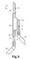
- FIG. 6is a profile view of a further exemplary linear cutter in accordance with the instant disclosure, which is coupled to two robotic arms.
- FIG. 7is a profile view of an exemplary cryosurgical probe in accordance with the instant disclosure, which is coupled to a robotic arm.
- FIG. 8is a photograph of the exemplary cryosurgical probe.
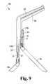
- FIG. 9is a profile view of an exemplary clamp in accordance with the instant disclosure, which is coupled to two robotic arms.
- FIG. 10is a profile view of another exemplary clamp in accordance with the instant disclosure, which is coupled to two robotic arms.
- FIG. 11is a profile view of an exemplary clip applicator in accordance with the instant disclosure, which is coupled to a robotic arm.
- FIG. 12is a profile view of another exemplary clip applicator in accordance with the instant disclosure, which is coupled to two robotic arms.
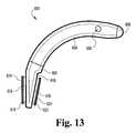
- FIG. 13is a profile view of an exemplary illuminated dissector in accordance with the instant disclosure.
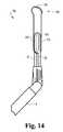
- FIG. 14is a profile view of an exemplary ablation pen in accordance with the instant disclosure, which is coupled to a robotic arm.
- FIGS. 15A and 15Bare bottom views of exemplary ablation rails in accordance with the instant disclosure.
- FIG. 15Cis a profile view of an exemplary ablation rail in accordance with the instant disclosure, which is coupled to a robotic arm.
- FIG. 16is a profile view of an exemplary ablation and sensing device in accordance with the instant disclosure, which is coupled to a robotic arm.
- FIG. 17is an elevated perspective view of the exemplary magnetic, bipolar ablation clamp in accordance with the instant disclosure.
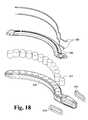
- FIG. 18is an exploded view of an exemplary jaw of the exemplary magnetic, bipolar ablation clamp of FIG. 17 .
- FIG. 19is a profile view of the exemplary magnetic, bipolar ablation clamp of FIG. 17 .
- FIG. 20is a longitudinal cross-sectional view of an exemplary magnetic, bipolar ablation clamp of FIG. 17 .
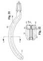
- FIG. 21is an overhead view of the exemplary jaw of the exemplary magnetic, bipolar ablation clamp of FIG. 17 .
- FIG. 22is a cross-sectional view of the exemplary magnetic, bipolar ablation clamp of FIG. 21 taken along line A-A.
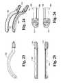
- FIG. 23is an overhead view of the exemplary magnetic, bipolar ablation clamp of FIG. 17 , in the open position.
- FIG. 24is an elevated perspective view of the exemplary magnetic, bipolar ablation clamp of FIG. 17 in the open position.
- FIG. 25is a profile view of the exemplary magnetic, bipolar ablation clamp of FIG. 17 in the open position.
- FIG. 26is an end view of the exemplary magnetic, bipolar ablation clamp of FIG. 17 in the open position.
- FIG. 27is an overhead view of the exemplary magnetic, bipolar ablation clamp of FIG. 17 in the closed position.
- FIG. 28is an elevated perspective view of the exemplary magnetic, bipolar ablation clamp of FIG. 17 in the closed position.
- FIG. 29is a profile view of the exemplary magnetic, bipolar ablation clamp of FIG. 17 in the closed position.
- FIG. 30is an end view of the exemplary magnetic, bipolar ablation clamp of FIG. 17 in the closed position.
- FIG. 31is a photograph of an exemplary robotic toolkit in accordance with the instant disclosure.
- FIG. 32is a photograph of the exemplary ablation pen/rail.
- FIG. 33is a photograph of the exemplary occlusion clip applicator.
- FIG. 34is a photograph of the exemplary magnetic, bipolar ablation clamp.
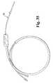
- FIG. 35is a photograph of the exemplary cryosurgical probe.
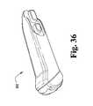
- FIG. 36is a photograph of the exemplary ablation pen.
- FIG. 37is a photograph of the exemplary illuminated dissector.
- an exemplary robotic control arm 10is a component of a telesurgical system (not shown).
- exemplary telesurgical systemsinclude those such as the daVinci® Surgical System, available from Intuitive Surgical, Inc. of Mountain View, Calif., disclosed in U.S. Pat. No. 6,770,081, the disclosure of which is incorporated herein by reference.
- the robotic control arm 10includes an elongated shaft 12 and an axial adjustment coupling 14 .
- a housing 16 at the proximal end of the shaft 12couples the control arm 10 to the telesurgical system.
- the housing 16contains the mechanism for controlling (e.g., rotating) the shaft 12 , articulating the coupling 14 , and actuating forceps 18 mounted to the coupling 14 .
- the forceps 18include a first jaw 20 , a second jaw 22 .
- the exemplary forceps 18is known as cardiere forceps in which each jaws 20 , 22 is fenestrated.
- each jaw 20 , 22is generally rectangular in shape, with rounded corners, and defines an oval opening 24 .
- this opening 24is adapted to engage with a projection to facilitate mounting the robotic arm 10 to an interchangeable surgical tool.
- an inner surface 26 of each jaw 20 , 22may be serrated or smooth.
- the jaws 20 , 22are repositionable anywhere between a fully open position and a closed position by movement of the mechanism located within the housing 16 . More specifically, either or both of the jaws 20 , 22 can be independently repositioned relative to one another.
- the robotic control arm 10is operative to deliver electrical current an interchangeable surgical tool (see FIGS. 1-30 , Appendices I & II), having an associated electrical load, when mounted to the robotic control arm 10 .
- the jaws 20 , 22comprise an electrode 40 mounted to an insulative supporting frame 42 .
- Each electrode 40is fabricated from an electrically conductive material, such as, without limitation, stainless steel, platinum, nickel, or aluminum.
- Direct currentis transmitted from an electrosurgical generator (now shown) via the wire leads 36 , 38 to the electrodes 40 .
- the electric currentis operative to flow between the jaws 20 , 22 when current is supplied by the electrosurgical generator and the jaws are in electrical communication with one another, such as by interposing an electrical lead and electrical load.
- various surgical toolsmay be used and exchanged for other surgical tools in an interchangeable manner.
- thisprovides flexibility in having one robotic arm and various separable surgical tools that are utilized to carry out specific tasks, one at a time.
- This flexibility and redundancy in utilizing the same robotic arm 10has particular benefit in a minimally invasive surgery procedure where, for example, the surgical tools to be used at part of the particular procedure may be inserted into the body cavity, creating what may be referred to as a toolkit or tool chest within the body cavity.
- surgeon or robotic instrumentmay use a single robotic arm 10 for grasping and using each surgical tool, as needed, without the need for repeatedly removing the robotic arm to exchange or replace the surgical tools.
- surgical toolsmay be for one-time use only and disposable, whereas the control arm, and any associated articulation control mechanism, is reusable, if so desired.
- FIG. 4illustrates an exemplary linear cutter 100 including a drive mechanism 102 and a pair of jaws 104 , 106 , at least one of which is pivotable relative to the other.
- the bottom jaw 104is repositionable, while the position of the top jaw 106 is fixed.
- These jaws 104 , 106are configured to staple and cut tissue placed therebetween generally in the manner described in U.S. Pat. No. 7,001,408, the disclosure of which is incorporated herein by reference.
- a robotic arm 10includes a pair of jaws 20 that engage a clamping area 108 of the linear cutter 100 in order to couple the robotic arm 10 to the linear cutter 100 .
- the clamping area 108 of the linear cutter 100includes a lateral base 122 having a predetermined thickness from which oblong projections 124 extend from opposite sides.
- an oblong pad 128Surrounding each oblong projection 124 and mounted to the base 122 is an oblong pad 128 (underneath the jaw 22 in FIG. 4 , for example), which is adapted to receive one of the jaws 20 , 22 of the robotic arm 10 .
- each pad 128includes an electrical contact in electrical communication with the drive mechanism 102 by way of a lead 126 .
- the jaws 20 , 22 of the robotic arm 10operate as bipolar electrical contacts, which provide electric current to the drive mechanism 102 of the linear cutter. Consequently, when the robotic arm 10 is coupled to the linear cutter 100 so the electrical contact of each pad 128 contacts a respective jaw 20 , 22 , electrical communication between the external power source and the drive mechanism 102 may be established.
- the jaws 20 , 22In order to establish electrical communication between the external power source and the drive mechanism 102 , the jaws 20 , 22 must be properly seated on the pads 128 . To properly seat the jaws 20 , 22 on the pads 128 , the jaws 20 , 22 are opened so that the oblong opening 24 of each jaw is aligned with and overlies one of the oblong projections 124 of the linear cutter 100 . Thereafter, the jaws 20 , 22 are moved toward one another so that the oblong projections 124 pierce the openings 24 of the jaws 20 , 22 , thereby orienting the jaws 20 , 22 to circumscribe the projections.
- an alternate exemplary linear cutter 150including a drive mechanism 152 and a pair of jaws 154 , 156 , at least one of which is pivotable relative to the other.
- the bottom jaw 154is repositionable, while the position of the top jaw 156 is fixed.
- These jaws 154 , 156are configured to staple and cut tissue placed therebetween generally in the manner described in U.S. Pat. No. 7,001,408, the disclosure of which is incorporated herein by reference.
- a robotic arm 10includes a pair of jaws 20 that engage at least one of the clamping areas 108 , 110 of the linear cutter 150 in order to couple the robotic arm 10 to the linear cutter 150 .
- a surgeonmay use the robotic arm 10 to position the linear cutter 100 as desired. Coupling the robotic arm 10 to the linear cutter 150 is generally the same as was described in the foregoing embodiment and has been omitted here only for purposes of brevity.
- the exemplary linear cutterincludes an external cable assembly 166 to drive and power the linear cutter in lieu of using the robotic arm 10 .
- the robotic arm 10may be utilized to power the stapling functionality, while the cable assembly is operative to power the cutting functionality, or vice versa.
- the cable assembly 166includes at least one cable (not shown) disposed within a sheath. The cable is configured to rotate and/or translate within sheath in order to transfer mechanical energy from an external source (not shown) to the linear cutter drive mechanism, thereby actuating at least one of the stapling and/or cutting functions of linear cutter 150 .
- a further alternate exemplary linear cutter 170including a manual drive mechanism 172 and a pair of jaws 174 , 176 , at least one of which is pivotable relative to the other.
- the bottom jaw 174is repositionable, while the position of the top jaw 176 is fixed.
- These jaws 174 , 176are configured to staple and cut tissue placed therebetween generally in the manner described in U.S. Pat. No. 7,001,408, the disclosure of which is incorporated herein by reference.
- the linear cutter 170includes a pair of clamping areas 108 , 110 , with each clamping area being coupled to a separate robotic arm 10 A, 10 B.
- the first clamping area 108is integral with the cutter housing 178 , while the second clamping area 110 slideably engages the cutter housing.
- the housing 178includes an electric motor operatively coupled to the bottom jaw 174 and a stapling mechanism (not shown) operatively coupled to the second clamping area 110 .
- the first robotic arm 10 Aprovides electrical power sufficient to power a motor (not shown) operatively coupled to the bottom jaw 174 .
- the stapling actionis carried out by repositioning the second robotic arm 10 B rearward, toward the first robotic arm 10 A, which causes the stapling mechanism to be repositioned, thereby causing the stapling action.
- repositioning the second robotic arm 10 B with respect to the first robotic arm 10 Amay control a variety of functions including cutting or a combination of cutting and stapling.
- an exemplary cryosurgical probe 200includes an ablation tube 202 .
- the ablation tube 202is selectively supplied with a cryogenic fluid (e.g., nitrous oxide, argon, etc.) via an umbilical line 204 , which is also operative to withdraw spent cryogenic fluid from a distal end of the tube 202 .
- the ablation tube 202may be constructed generally as described in U.S. Pat. No. 3,993,075, the disclosure of which is incorporated by reference, as well as constructed in accordance with U.S. patent application Ser. No. 12/727,995, filed Mar. 19, 2010 and published as US 2010/0241114 on Sep. 23, 2010, the disclosures of which are incorporated herein by reference.
- a cryogenic fluid conduit 208Housed within the ablation tube 202 is a cryogenic fluid conduit 208 having one or more exit orifices (not shown) that are in communication with an interior of the tube.
- the cryogenic fluid conduit 208also extends through the umbilical line 204 and is in fluid communication with an external cryogenic fluid source (not shown).
- An electrically actuated valve 212may be placed in series with the cryogenic fluid conduit 208 that is operative to selectively allow cryogenic fluid flowing through the umbilical line 204 to reach the exit orifices. In order to manipulate the valve 212 , electrical power is provided by the robotic arm 10 .
- the cryosurgical probe 200includes a clamping area 218 having a lateral base 222 with a predetermined thickness from which oblong projections 224 extend from opposite sides. Surrounding each oblong projection 224 and mounted to the base 222 is an oblong pad, which is adapted to receive one of the jaws 20 , 22 of the robotic arm 10 . More specifically, each pad includes an electrical contact in electrical communication with the valve 212 by way of a lead. As was discussed in more detail previously, the jaws 20 , 22 of the robotic arm 10 include bipolar electrical contacts in electrical communication with an external power source (not shown). Thus, when the robotic arm 10 is coupled to the cryosurgical probe 200 so the electrical contacts of the pads touch the jaws 20 , 22 , electrical communication between the external power source and the valve 212 may be established.
- the exemplary cryosurgical probe 200may be used in surgical procedures including, without limitation, atrial tissue ablation to treat atrial fibrillation.
- a surgeonmay use the robotic arm 10 to position, orient, and/or move cryosurgical probe 200 as desired. More specifically, the separability of the cryosurgical probe 200 from the robotic arm 10 enables the robotic arm to be utilized with additional devices, such as the linear cutter 100 discussed above, without ever removing the robotic arm from the patient's body. This is particularly advantageous in minimally invasive procedures.
- cryosurgical probemay include the structure as disclosed in Appendix I, attached hereto and made part of the instant disclosure.
- FIG. 9illustrates an exemplary clamp 300 having opposed jaws 302 , 304 for use with a pair of robotic arm assemblies 10 A, 10 B (see FIG. 1 ).
- the jaws 302 , 304are similar to those generally described in U.S. Pat. No. 6,923,806, the disclosure of which is incorporated herein by reference.
- the illustrated clamping jaws 302 , 304include an elongated electrode (not shown) that is adapted to receive bipolar RF energy for creating transmural ablation lines in tissue held between the jaws 302 , 304 .
- the distal jaw 302is considered to be stationary, while the proximal jaw 304 traverses longitudinally along a track (not shown) formed within the longitudinal portion of the distal jaw 302 .
- each of the jaws 302 , 304is coupled to a separate robotic arm 10 A, 10 B, each jaw is able to move independent of the other based upon relative movement of the robotic arms 10 A, 10 B with respect to one another.
- each armis initially aligned with its corresponding clamping area 318 .
- Each of the jaws 302 , 304includes a clamping area 318 A, 318 B that comprises a base 322 with a predetermined thickness from which oblong projections 324 extend from opposite sides.
- the clamping area 318 B for the distal jaw 302extends longitudinally from a proximal end of the longitudinal portion.
- the clamping area 318 A for the proximal jaw 304extends proximally and laterally from a proximal end of the proximal jaw.
- This orientation of the clamping areas 318 A, 318 Ballows the robotic arms 10 A, 10 B to individually couple to the jaws 302 , 304 , while preserving the necessary range of motion needed by the robotic arms to open and close the jaws their own jaws 20 , 22 .
- each oblong projection 324 and mounted to the base 322Surrounding each oblong projection 324 and mounted to the base 322 is an oblong pad, which is adapted to receive one of the jaws 20 , 22 of a robotic arm 10 A, 10 B. More specifically, each pad includes an electrical contact in electrical communication, via an electrical lead (not shown), with the elongated electrode (not shown) that is adapted to receive bipolar RF energy for creating transmural ablation lines.
- both jaws 20 , 22 of each robotic arm 10 A, 10 Binclude a bipolar electrical contact in electrical communication with an external power source (not shown) by way individual leads (see FIGS. 2A , 2 B). Consequently, when a robotic arm 10 A, 10 B is coupled to a respective jaw 302 , 304 so the electrical contact of a pad associated with the clamp touches the electrical contacts of the jaws 20 , 22 , electrical communication between the external power source and clamp electrodes (i.e., the electrical load) can be established.
- the clamp 300may be released from the robotic arms 10 A, 10 B and a different surgical tool attached to the robotic arms. This separability and interchangeability allows a surgeon to select multiple surgical tools and position these tools at a preselected location in or near the surgical site for convenience during a surgical procedure, such as a minimally invasive surgical procedure.
- the surgical toolsare inserted into the body cavity, creating what may be referred to as a tool kit or tool chest within the body cavity, and the surgeon uses one or more robotic arms 10 A, 10 B to selectively couple, reposition, and power the surgical tool necessary to perform all or a portion of the surgical procedure without the need for repeatedly removing one or more of the robotic arms and/or surgical tools.
- the surgical toolse.g., described above in exemplary form as a linear cutter 100 , 150 , 170 , a cryosurgical probe 200 , and a clamp 300
- the robotic arms 10 , 10 A, 10 Bbeing reusable, if so desired.
- FIG. 10illustrates an exemplary in-line clamp 400 , which may be fabricated in accordance with the disclosure of U.S. patent application Ser. No. 12/748,842, entitled “SURGICAL CLAMP,” the disclosure of which is incorporated herein by reference.
- This exemplary in-line clamp 400includes a pair of jaws 404 , 406 , that open and close in two stages. Starting from a closed position, the jaws 404 , 406 are progressively apart from one another, but maintain a generally parallel configuration. At a predetermined point, the jaws 404 , 406 flare out from one another and discontinue a parallel configuration. As the jaws 404 , 406 are opened to a maximum, the distal ends of the jaws are the portions farthest apart from one another, while the proximal ends are spaced apart from one another, but significantly closer than are the distal ends.
- This exemplary in-line clamp 400includes two robotic arm clamping areas 418 A, 418 B, each being on an opposite side of the clamp housing 408 . Similar to the embodiments discussed previously, each clamping area 418 A, 418 B includes a base with a predetermined thickness from which oblong projections 424 extend from opposite sides. Because the clamping areas 418 A, 418 B are on opposite sides of the housing 408 , separate robotic arms 10 A, 10 B may be coupled to the clamp by way of the clamping areas. Moreover, this orientation of the clamping areas 418 A, 418 B also preserves a range of motion for each robotic arm 10 A, 10 B, which is useful to open and close the jaws 404 , 406 .
- the first clamping area 418 Ais fixedly mounted to the clamp housing 408 and to the first robotic arm 10 A, whereas the second clamping area 418 B is part of a carriage that is repositionably mounted to the clamp housing 408 .
- the robotic arms 10 A, 10 Bare repositionable with respect to one another even when mounted to respective clamping areas 418 A, 418 B.
- Articulation of jaws 404 , 406may be effectuated by moving one of the robotic arms 10 A with respect to the other robotic arm 10 B.
- robotic arm 10 A, 10 Bis moved, if only one, is not as important as the relative motion between the robotic arms.
- the first robotic arm 10 Ais kept stationary, while the second robotic arm 10 B is repositioned proximally, away from the jaws 404 , 406 .
- the jaws 404 , 406may be repositioned using an electric motor (not shown).
- the electric motoris located within the in-line clamp housing 408 .
- the electric motoris operatively coupled to the jaws 404 , 406 by way of a repositioning mechanism.
- This repositioning mechanismmay comprise any combination of gears, pulleys, and cord to convert the motion of the electric motor into motion of the jaws 404 , 406 .
- the electric motoris operatively coupled to one or more gears, which are coupled to a rack (see rack 832 from U.S. patent application Ser. No. 12/748,842) in order to reposition the rack with respect to gears directly mounted to the jaws 404 , 406 .
- the electric motormay be powered by either robotic arm 10 A, 10 B based upon the electrical communication established between the robotic arms and the clamping areas 418 A, 418 B.
- FIG. 11illustrates an exemplary clip applicator 500 being coupled to a robotic arm 10 .
- the clip applicator 500includes a rounded rectangular frame 502 that defines a working area 504 .
- an occlusion clip 506mounted to the rectangular frame 502 using two sutures 512 .
- the clip 506includes an upper jaw 508 and a lower jaw 510 that are biased in the closed position, as shown in FIG. 11 .
- a first end of each suture 512is wound around a respective clip jaw and threaded along the rectangular frame 502 to extend into an applicator housing 514 , where a second end of each suture is wound around a spool 516 .
- an electric motor 517operatively coupled to the spool 516 in order to rotate the spool and wind additional suture on the spool or unwind suture from the spool.
- the clip jaws 508 , 510are pulled apart so that a patient's tissue may be repositioned to interposes the jaws, after which time the spool is unwound or the sutures are severed to clamp the tissue between the jaws 508 , 510 .
- the clip applicator 500includes clamping areas 518 .
- Each clamping area 518shares a base 522 with a predetermined thickness from which oblong projections 524 extend from opposite sides.
- the clamping areas 418extends from a proximal side of the applicator housing 514 .
- an alternate exemplary clip applicator 530does not include an electric motor, but does include several of the aforementioned features/elements from the previous clip applicator 500 .
- the spool 516is locked so that no further rotational motion is permitted.
- the spool 516is longitudinally repositionable along a track 532 formed into the applicator housing 534 .
- the clamping area 518 A for the second robotic arm 10 Ais repositionably mounted to the applicator housing.
- the clamping area 518 Aincludes an appendage 536 that extends into the applicator housing 534 and is operatively coupled to the spool 516 .
- this appendage 436is repositionable along the track 532 so that longitudinal motion of the appendage is operative to longitudinally reposition the spool 516 a corresponding distance.
- the spool 516In operation, in order to overcome the bias of the clip jaws 508 , 510 , the spool 516 is longitudinally repositioned toward the proximal end of the applicator housing 534 . This movement of the spool 516 correspondingly causes the sutures 512 to become tensioned to a sufficient degree to overcome the bias of the clip jaws 508 , 510 , thereby causing the sutures to effectively pull apart the clip jaws.
- the first robotic arm 10 Bis maintained in a first position, which is operative to maintain the applicator housing 534 in the same first position, while the second robotic arm 10 A is repositioned proximally with respect to the first position, thereby moving the second robotic arm 10 A, the appendage 536 , and the spool 516 proximally.
- the net movement between the first robotic arm 10 B and the second robotic arm 10 Acauses the spool 516 to be repositioned along the track 532 .
- the suturesare severed or the robotic arms 10 A, 10 B are relatively repositioned to cause the spool 516 to move distally so the sutures are no longer operative to retard the jaws from clamping toward one another.
- the clip applicatormay include the structure as disclosed in Appendix II, attached hereto and made part of the instant disclosure.
- FIG. 13illustrates an exemplary illuminated dissector 600 , which may be generally similar to the dissectors described in U.S. Patent Application Publication No. 2005/0203561 (U.S. patent application Ser. No. 10/796,901), the disclosure of which is incorporated herein by reference.
- This exemplary dissector 600includes clamping areas 618 on a support 602 from which extends a flexible appendage 604 .
- the flexible appendage 604includes a suture hole 606 and a light emitting diode (LED) 608 at its distal tip.
- LEDlight emitting diode
- electrical leadsextend from the LED and into electrical communication with the electrical contacts of the pads 626 of the clamping areas 618 .
- the clamping areas 618are similar in structure to the clamping areas described in the foregoing embodiments and, for purposes of brevity, a detailed explanation of the structure of these clamping areas 618 has been omitted.
- Repositioning of the dissector 600 and illumination of the LED 608are both controlled by a robotic arm (not shown) mounted thereto. Consistent with the foregoing embodiments (see FIGS. 1-3 ), the jaws 20 , 22 of the robotic arm 10 must be properly seated on the pads 626 . To do this, the jaws 20 , 22 are opened so that the oblong opening 24 of each jaw is aligned with and overlies one of the oblong projections 624 of the dissector 600 .
- the jaws 20 , 22are moved toward one another so that the oblong projections 624 pierce the openings 24 of the jaws 20 , 22 , thereby orienting the jaws 20 , 22 to circumscribe the projections and ultimately sandwich the base 622 therebetween in a compression fit.
- This compression fitalso establishes electrical communication between the contacts of the jaws 20 , 22 and the contacts of the pads 626 , which ultimately establishes electrical communication between the LED 608 and an external power source (not shown).
- an external power sourcenot shown
- FIG. 14illustrates an exemplary ablation pen 700 , having a distal portion 702 generally similar to the ablation device disclosed in U.S. Patent Application Publication No. 2008/0009853 (U.S. patent application Ser. No. 11/457,919), the disclosure of which is incorporated herein by reference.
- the ablation pen 700includes clamping areas 718 similar those to the clamping areas disclosed in the foregoing exemplary embodiments. To further brevity, a detailed discussion of the structure of the clamping areas 718 has been omitted.
- the distal portion 702includes an ablation electrode 704 that is in electrical communication with the robotic jaws 20 , 22 by way of an electric lead (not shown) extending between the clamping area 718 and the electrode.
- Repositioning of the ablation pen 700 and energizing the ablation electrode 704are both controlled by the robotic arm 10 mounted thereto. Consistent with the foregoing embodiments, the jaws 20 , 22 of the robotic arm 10 must be properly seated on the pads 726 . To do this, the jaws 20 , 22 are opened so that the oblong opening 24 of each jaw is aligned with and overlies one of the oblong projections 724 of the ablation pen 700 .
- the jaws 20 , 22are moved toward one another so that the oblong projections 724 pierce the openings 24 of the jaws 20 , 22 , thereby orienting the jaws 20 , 22 to circumscribe the projections and ultimately sandwich the clamping area 818 therebetween in a compression fit.
- This compression fitalso establishes electrical communication between the contacts 40 of the jaws 20 , 22 and the contacts of the pads 726 , which ultimately establishes electrical communication between the ablation electrode 804 and an external power source (not shown).
- an external power sourcenot shown.
- FIGS. 15A , 15 B, and 15 Cillustrate exemplary linear ablation pens 800 , 802 , 804 .
- the first linear ablation pen 800includes at least one ablation electrode 810 and at least one recording electrode 812 that are in electrical communication with electrical contacts associated with the clamping area 818 .
- the clamping areas 818extend laterally outward from a surface perpendicular to the electrode contact surface. Because there are at least two pair of clamping areas 818 , the linear ablation pen 800 may be transferred from a first robotic arm (see, e.g., 10 A in FIG. 9 ) to a second robotic arm (see, e.g., 10 B in FIG.
- multiple clamping areas 818allow for repositioning of the pen 800 using one or both robotic arms.
- the first robotic armgrasps the first clamping area 818 and is utilized for sensing electrical signals (such as those associated with the heart) by detecting current using the recording electrode 812 .
- the second robotic armgrasps the second clamping area 818 and is utilized for powering the ablation electrode 810 .
- the second linear ablation pen 802includes at least one ablation electrode 810 that is in electrical communication with electrical contacts associated with the clamping area 818 .
- the clamping areas 818extend laterally outward from a surface perpendicular to the electrode contact surface. Because there are at least two pair of clamping areas 818 , the linear ablation pen 802 may be transferred between a first robotic arm to a second robotic arm without the pen 802 ever being completely uncoupled from all robotic arms. In addition, multiple clamping areas 818 allow for repositioning of the pen 802 using one or both robotic arms.
- the third linear ablation pen 804includes at least one ablation electrode 810 that is in electrical communication with electrical contacts associated with the clamping area 818 .
- the clamping areas 818extend laterally outward from a surface parallel to the electrode contact surface.
- FIG. 16illustrates an exemplary ablation and sensing device 900 that is mounted to a robotic arm 10 .
- the ablation and sensing device 900includes clamping areas 918 that engages the jaws 20 , 22 of the robotic arm 10 in order to establish physical and electrical communication between a remote power source (not shown) and an ablation electrode 902 .
- At least one sensing electrode 904is also mounted to the ablation and sensing device 900 .
- a tether 906extends between the sensing electrode 904 and an external monitoring device (not shown) in order for the electronic monitoring device to receive signals from the sensing electrode.
- Repositioning of the ablation and sensing device 900 and energizing the ablation electrode 902are both controlled by the robotic arm 10 mounted thereto. Consistent with the foregoing embodiments, the jaws 20 , 22 of the robotic arm 10 must be properly seated on the pads 926 . To do this, the jaws 20 , 22 are opened so that the oblong opening 24 of each jaw is aligned with and overlies one of the oblong projections 924 of the ablation and sensing device 900 .
- the jaws 20 , 22are moved toward one another so that the oblong projections 924 pierce the openings 24 of the jaws 20 , 22 , thereby orienting the jaws 20 , 22 to circumscribe the projections and ultimately sandwich the base 922 therebetween in a compression fit.
- This compression fitalso establishes electrical communication between the contacts of the jaws 20 , 22 and the contacts of the pads 926 , which ultimately establishes electrical communication between the ablation electrode 902 and an external power source (not shown).
- an external power sourcenot shown.
- an exemplary magnetic, bipolar ablation clamp 1000utilizes two separate clamping jaws 1002 , 1004 , with each respective clamping jaw being controlled by a separate robotic arm with grasping jaws 20 , 22 (i.e., endoscopic graspers).
- Each clamping jaw 1002 , 1004includes at least one electrode 1006 , insulative contact surfaces 1008 , and a support frame 1010 .
- Within each jaw 1002 , 1004are a series of magnets 1012 used to couple one jaw to another.
- Each electrode 1006communicates with a contact 1014 , which in turn engages with the electrode 40 of the jaws 20 , 22 of the robotic arm 10 to create an electrical pathway extending between the electrodes 1006 and the electric source, such as an electric generator (not shown).
- the jaws 1002 , 1004are positioned on either side of the tissue to be ablated.
- One or both jaws 1002 , 1004are released from the robotic arms 10 A, 10 B, thereby allowing the magnet 1012 to couple the jaws 1002 , 1004 about the tissue.
- the jaws 1002 , 1004are re-engaged by the respective robotic arms 10 A, 10 B in order to establish electrical communication between the electrodes 40 of the robotic jaws 20 , 22 and the contacts 1014 of the respective jaws 1002 , 1004 that are in electrical communication with the electrodes 1006 .
- electric energyis delivered to the electrodes 40 of the robotic jaws 20 , 22 to provide electric current to the electrodes 1006 , thus ablating the tissue in contact with the electrodes 1006 .
- an exemplary robotic toolkitcomprises an exemplary cryosurgical probe 200 (with or without a swivel—see Appendix I), an exemplary occlusion clip applicator 500 , 530 (including those disclosed in Appendix II), an exemplary illuminated dissector 700 , an exemplary ablation pen 800 , another ablation pen/rail 900 , and an exemplary magnetic, bipolar ablation clamp 1000 .
- FIG. 32is a photograph of the exemplary ablation pen/rail 900 .
- FIG. 33is a photograph of the exemplary occlusion clip applicator 500 .
- FIG. 34is a photograph of the exemplary magnetic, bipolar ablation clamp 1000 .
- FIG. 35is a photograph of the exemplary cryosurgical probe 200 .
- FIG. 36is a photograph of the exemplary ablation pen 800 .
- FIG. 37is a photograph of the exemplary illuminated dissector 700 .
Landscapes
- Health & Medical Sciences (AREA)
- Surgery (AREA)
- Life Sciences & Earth Sciences (AREA)
- Engineering & Computer Science (AREA)
- Nuclear Medicine, Radiotherapy & Molecular Imaging (AREA)
- Medical Informatics (AREA)
- Biomedical Technology (AREA)
- Heart & Thoracic Surgery (AREA)
- Molecular Biology (AREA)
- Animal Behavior & Ethology (AREA)
- General Health & Medical Sciences (AREA)
- Public Health (AREA)
- Veterinary Medicine (AREA)
- Otolaryngology (AREA)
- Physics & Mathematics (AREA)
- Plasma & Fusion (AREA)
- Robotics (AREA)
- Surgical Instruments (AREA)
Abstract
Description
Claims (19)
Priority Applications (3)
| Application Number | Priority Date | Filing Date | Title |
|---|---|---|---|
| US13/477,761US9066741B2 (en) | 2010-11-01 | 2012-05-22 | Robotic toolkit |
| US14/748,755US9561065B2 (en) | 2010-11-01 | 2015-06-24 | Robotic toolkit |
| US15/423,139US10085788B2 (en) | 2010-11-01 | 2017-02-02 | Robotic toolkit |
Applications Claiming Priority (3)
| Application Number | Priority Date | Filing Date | Title |
|---|---|---|---|
| US40899310P | 2010-11-01 | 2010-11-01 | |
| US201113286554A | 2011-11-01 | 2011-11-01 | |
| US13/477,761US9066741B2 (en) | 2010-11-01 | 2012-05-22 | Robotic toolkit |
Related Parent Applications (1)
| Application Number | Title | Priority Date | Filing Date |
|---|---|---|---|
| US201113286554AContinuation | 2010-11-01 | 2011-11-01 |
Related Child Applications (1)
| Application Number | Title | Priority Date | Filing Date |
|---|---|---|---|
| US14/748,755ContinuationUS9561065B2 (en) | 2010-11-01 | 2015-06-24 | Robotic toolkit |
Publications (2)
| Publication Number | Publication Date |
|---|---|
| US20120323256A1 US20120323256A1 (en) | 2012-12-20 |
| US9066741B2true US9066741B2 (en) | 2015-06-30 |
Family
ID=47354276
Family Applications (3)
| Application Number | Title | Priority Date | Filing Date |
|---|---|---|---|
| US13/477,761Active2032-11-30US9066741B2 (en) | 2010-11-01 | 2012-05-22 | Robotic toolkit |
| US14/748,755ActiveUS9561065B2 (en) | 2010-11-01 | 2015-06-24 | Robotic toolkit |
| US15/423,139ActiveUS10085788B2 (en) | 2010-11-01 | 2017-02-02 | Robotic toolkit |
Family Applications After (2)
| Application Number | Title | Priority Date | Filing Date |
|---|---|---|---|
| US14/748,755ActiveUS9561065B2 (en) | 2010-11-01 | 2015-06-24 | Robotic toolkit |
| US15/423,139ActiveUS10085788B2 (en) | 2010-11-01 | 2017-02-02 | Robotic toolkit |
Country Status (1)
| Country | Link |
|---|---|
| US (3) | US9066741B2 (en) |
Cited By (2)
| Publication number | Priority date | Publication date | Assignee | Title |
|---|---|---|---|---|
| US11653930B2 (en)* | 2016-08-08 | 2023-05-23 | Atricure, Inc. | Robotic assisted clip applier |
| US11678928B2 (en) | 2019-01-10 | 2023-06-20 | Atricure, Inc. | Surgical clamp |
Families Citing this family (52)
| Publication number | Priority date | Publication date | Assignee | Title |
|---|---|---|---|---|
| US9232959B2 (en) | 2007-01-02 | 2016-01-12 | Aquabeam, Llc | Multi fluid tissue resection methods and devices |
| US12290277B2 (en) | 2007-01-02 | 2025-05-06 | Aquabeam, Llc | Tissue resection with pressure sensing |
| ES2769535T3 (en) | 2008-03-06 | 2020-06-26 | Aquabeam Llc | Tissue ablation and cauterization with optical energy carried in a fluid stream |
| EP3351196A1 (en) | 2012-02-29 | 2018-07-25 | Procept Biorobotics Corporation | Automated image-guided tissue resection and treatment |
| US10231867B2 (en) | 2013-01-18 | 2019-03-19 | Auris Health, Inc. | Method, apparatus and system for a water jet |
| US20140276968A1 (en)* | 2013-03-14 | 2014-09-18 | Ethicon, Inc. | Applicator systems for surgical fasteners |
| WO2014201165A1 (en) | 2013-06-11 | 2014-12-18 | Auris Surgical Robotics, Inc. | System for robotic assisted cataract surgery |
| US10426661B2 (en) | 2013-08-13 | 2019-10-01 | Auris Health, Inc. | Method and apparatus for laser assisted cataract surgery |
| US20160287279A1 (en) | 2015-04-01 | 2016-10-06 | Auris Surgical Robotics, Inc. | Microsurgical tool for robotic applications |
| US9955986B2 (en) | 2015-10-30 | 2018-05-01 | Auris Surgical Robotics, Inc. | Basket apparatus |
| US10231793B2 (en) | 2015-10-30 | 2019-03-19 | Auris Health, Inc. | Object removal through a percutaneous suction tube |
| US9949749B2 (en) | 2015-10-30 | 2018-04-24 | Auris Surgical Robotics, Inc. | Object capture with a basket |
| US10799308B2 (en)* | 2017-02-09 | 2020-10-13 | Vicarious Surgical Inc. | Virtual reality surgical tools system |
| CN108934160B (en) | 2017-03-28 | 2021-08-31 | 奥瑞斯健康公司 | Shaft actuating handle |
| EP3606400B1 (en) | 2017-04-07 | 2022-03-09 | Auris Health, Inc. | Patient introducer alignment |
| US11045175B2 (en)* | 2017-08-14 | 2021-06-29 | C.R. Bard, Inc. | Surgical device for use with robotic surgical systems |
| JP7267309B2 (en) | 2018-06-07 | 2023-05-01 | オーリス ヘルス インコーポレイテッド | Robotic medical system with high-strength instruments |
| JP7391886B2 (en) | 2018-06-28 | 2023-12-05 | オーリス ヘルス インコーポレイテッド | Medical system incorporating pulley sharing |
| US11179185B2 (en)* | 2018-07-20 | 2021-11-23 | Atricure, Inc. | Cryogenic surgical systems |
| WO2020036685A1 (en) | 2018-08-15 | 2020-02-20 | Auris Health, Inc. | Medical instruments for tissue cauterization |
| WO2020036686A1 (en) | 2018-08-17 | 2020-02-20 | Auris Health, Inc. | Bipolar medical instrument |
| WO2020055795A1 (en)* | 2018-09-10 | 2020-03-19 | Activ Surgical, Inc. | Surgical grasper with integrated suture pulley |
| US11628007B2 (en)* | 2018-09-14 | 2023-04-18 | Atricure, Inc. | Cryoprobe |
| CN112770689B (en) | 2018-09-26 | 2024-07-19 | 奥瑞斯健康公司 | Systems and instruments for suction and irrigation |
| US11576738B2 (en) | 2018-10-08 | 2023-02-14 | Auris Health, Inc. | Systems and instruments for tissue sealing |
| WO2020081651A1 (en) | 2018-10-16 | 2020-04-23 | Activ Surgical, Inc. | Autonomous methods and systems for tying surgical knots |
| WO2020131529A1 (en) | 2018-12-20 | 2020-06-25 | Auris Health, Inc. | Shielding for wristed instruments |
| EP3883492B1 (en) | 2019-01-25 | 2025-05-21 | Auris Health, Inc. | Vessel sealer with heating capabilities |
| EP3908201B1 (en) | 2019-03-25 | 2024-04-24 | Auris Health, Inc. | Instruments for medical stapling |
| CN114126529A (en) | 2019-06-25 | 2022-03-01 | 奥瑞斯健康公司 | Medical instrument including a wrist with hybrid redirecting surfaces |
| WO2020263629A1 (en) | 2019-06-27 | 2020-12-30 | Auris Health, Inc. | Systems and methods for a medical clip applier |
| WO2020263949A1 (en) | 2019-06-28 | 2020-12-30 | Auris Health, Inc. | Medical instruments including wrists with hybrid redirect surfaces |
| US11896330B2 (en) | 2019-08-15 | 2024-02-13 | Auris Health, Inc. | Robotic medical system having multiple medical instruments |
| US10959792B1 (en) | 2019-09-26 | 2021-03-30 | Auris Health, Inc. | Systems and methods for collision detection and avoidance |
| WO2021059100A1 (en) | 2019-09-26 | 2021-04-01 | Auris Health, Inc. | Systems and methods for collision avoidance using object models |
| US11737845B2 (en) | 2019-09-30 | 2023-08-29 | Auris Inc. | Medical instrument with a capstan |
| US11737835B2 (en) | 2019-10-29 | 2023-08-29 | Auris Health, Inc. | Braid-reinforced insulation sheath |
| CN114727850A (en) | 2019-11-21 | 2022-07-08 | 奥瑞斯健康公司 | Systems and methods for draping surgical systems |
| EP4084724A4 (en) | 2019-12-31 | 2023-12-27 | Auris Health, Inc. | ADVANCED BASKET DRIVE MODE |
| CN114901188A (en) | 2019-12-31 | 2022-08-12 | 奥瑞斯健康公司 | Dynamic pulley system |
| US12370002B2 (en) | 2020-03-30 | 2025-07-29 | Auris Health, Inc. | Workspace optimization for robotic surgery |
| CN115802975A (en) | 2020-06-29 | 2023-03-14 | 奥瑞斯健康公司 | System and method for detecting contact between a connecting rod and an external object |
| CN115734765A (en) | 2020-06-30 | 2023-03-03 | 奥瑞斯健康公司 | Robotic medical system with crash proximity indicator |
| US11357586B2 (en) | 2020-06-30 | 2022-06-14 | Auris Health, Inc. | Systems and methods for saturated robotic movement |
| US20220192733A1 (en)* | 2020-12-10 | 2022-06-23 | Atricure, Inc. | Minimally invasive surgery ablation clamp with cam mechanism |
| CN113117219B (en)* | 2021-04-19 | 2022-11-25 | 青岛大学附属医院 | Novel three-way guide wire guiding forceps for minimally invasive pancreatitis surgery |
| TWI850880B (en) | 2021-11-30 | 2024-08-01 | 美商安督奎斯特機器人公司 | Disposable end effectors, medical device, and operating method thereof |
| TWI835436B (en) | 2021-11-30 | 2024-03-11 | 美商安督奎斯特機器人公司 | Steerable overtube assemblies for robotic surgical systems, control assemblies and method thereof |
| WO2023101974A1 (en) | 2021-11-30 | 2023-06-08 | Endoquest Robotics, Inc. | Force transmission systems for robotically controlled medical devices |
| EP4440481A1 (en) | 2021-11-30 | 2024-10-09 | Endoquest Robotics, Inc. | Barrier drape adapters for robotic surgical systems |
| WO2023101948A1 (en) | 2021-11-30 | 2023-06-08 | Endoquest, Inc. | Master control systems for robotic surgical systems |
| TWI838986B (en) | 2021-11-30 | 2024-04-11 | 美商安督奎斯特機器人公司 | Patient console, robotic surgical system having the same, and method for performing the same |
Citations (136)
| Publication number | Priority date | Publication date | Assignee | Title |
|---|---|---|---|---|
| US2060724A (en) | 1935-01-19 | 1936-11-10 | William B Carroll | Surgical implement |
| US2371978A (en) | 1941-12-13 | 1945-03-20 | Roy G Perham | Clamp for retaining the edges of a wound in apposition |
| US3032039A (en) | 1959-05-26 | 1962-05-01 | Jack O Beaty | Arterial and veinous clamp and clamp applicator |
| US3496932A (en) | 1967-12-22 | 1970-02-24 | Gen Motors Corp | Method and apparatus for substernal cardiac massage |
| US3682180A (en) | 1970-06-08 | 1972-08-08 | Coilform Co Inc | Drain clip for surgical drain |
| US3854482A (en) | 1972-11-22 | 1974-12-17 | Avis Res Inc | Umbilical cord clamp |
| US3856017A (en) | 1972-02-24 | 1974-12-24 | A Chancholle | Apparatus for ligating sectioned blood vessels |
| US3856018A (en) | 1973-02-26 | 1974-12-24 | P Perisse | Process for ligating sectioned blood vessels |
| US3856016A (en) | 1972-11-03 | 1974-12-24 | H Davis | Method for mechanically applying an occlusion clip to an anatomical tubular structure |
| US3954108A (en) | 1972-11-03 | 1976-05-04 | Davis Hugh J | Occlusion clip and instrument for applying same |
| US4226239A (en) | 1978-01-31 | 1980-10-07 | Kli, Inc. | Surgical ligating instrument and method |
| US4274415A (en) | 1976-07-16 | 1981-06-23 | Maruho Co., Ltd. | Surgical clip and its assembly |
| US4493319A (en) | 1981-06-29 | 1985-01-15 | Cabot Medical Corporation | Ring applicator having floating inner tube |
| US4552128A (en) | 1983-12-29 | 1985-11-12 | Haber Terry M | Elastomechanical sphincter |
| US4788966A (en) | 1987-05-14 | 1988-12-06 | Inbae Yoon | Plug for use in a reversible sterilization procedure |
| US4791707A (en) | 1986-08-26 | 1988-12-20 | Tucker Wilson H | Clip applicator, spreadable clips and method for applying the clips |
| US4869268A (en) | 1987-05-14 | 1989-09-26 | Inbae Yoon | Multi-functional instruments and stretchable ligating and occluding devices |
| US4917677A (en) | 1989-03-29 | 1990-04-17 | Mccarthy John A | Surgical clamp assembly and method |
| US4950284A (en) | 1987-11-03 | 1990-08-21 | United States Surgical Corporation | Fascia clip |
| US5026379A (en) | 1989-12-05 | 1991-06-25 | Inbae Yoon | Multi-functional instruments and stretchable ligating and occluding devices |
| US5100416A (en) | 1989-10-17 | 1992-03-31 | Edward Weck Incorporated | Ligating clip applying instrument |
| US5119804A (en) | 1990-11-19 | 1992-06-09 | Anstadt George L | Heart massage apparatus |
| US5171250A (en) | 1987-05-14 | 1992-12-15 | Inbae Yoon | Surgical clips and surgical clip applicator and cutting and transection device |
| US5217030A (en) | 1989-12-05 | 1993-06-08 | Inbae Yoon | Multi-functional instruments and stretchable ligating and occluding devices |
| US5217473A (en) | 1989-12-05 | 1993-06-08 | Inbae Yoon | Multi-functional instruments and stretchable ligating and occluding devices |
| US5258000A (en) | 1991-11-25 | 1993-11-02 | Cook Incorporated | Tissue aperture repair device |
| US5282829A (en) | 1991-08-15 | 1994-02-01 | United States Surgical Corporation | Hollow body implants |
| US5290299A (en) | 1991-12-11 | 1994-03-01 | Ventritex, Inc. | Double jaw apparatus for attaching implanted materials to body tissue |
| US5306234A (en) | 1993-03-23 | 1994-04-26 | Johnson W Dudley | Method for closing an atrial appendage |
| US5309927A (en) | 1992-10-22 | 1994-05-10 | Ethicon, Inc. | Circular stapler tissue retention spring method |
| US5336252A (en) | 1992-06-22 | 1994-08-09 | Cohen Donald M | System and method for implanting cardiac electrical leads |
| US5342373A (en) | 1992-09-14 | 1994-08-30 | Ethicon, Inc. | Sterile clips and instrument for their placement |
| US5366459A (en) | 1987-05-14 | 1994-11-22 | Inbae Yoon | Surgical clip and clip application procedures |
| US5425740A (en) | 1994-05-17 | 1995-06-20 | Hutchinson, Jr.; William B. | Endoscopic hernia repair clip and method |
| US5439156A (en) | 1992-02-07 | 1995-08-08 | Ethicon, Inc. | Surgical anastomosis stapling instrument with flexible support shaft and anvil adjusting mechanism |
| US5452733A (en) | 1993-02-22 | 1995-09-26 | Stanford Surgical Technologies, Inc. | Methods for performing thoracoscopic coronary artery bypass |
| US5549628A (en) | 1994-02-10 | 1996-08-27 | Bio-Vascular, Inc. | Soft tissue stapling buttress |
| US5582616A (en) | 1994-08-05 | 1996-12-10 | Origin Medsystems, Inc. | Surgical helical fastener with applicator |
| US5609599A (en) | 1995-07-27 | 1997-03-11 | Levin; John M. | Leak clip |
| US5620452A (en) | 1994-12-22 | 1997-04-15 | Yoon; Inbae | Surgical clip with ductile tissue penetrating members |
| US5665100A (en) | 1989-12-05 | 1997-09-09 | Yoon; Inbae | Multifunctional instrument with interchangeable operating units for performing endoscopic procedures |
| US5667518A (en) | 1995-10-02 | 1997-09-16 | Pannell; William P. | Method and implements for performing a vasectomy |
| US5681330A (en) | 1994-03-02 | 1997-10-28 | Ethicon Endo-Surgery, Inc. | Sterile occlusion fasteners and instrument and method for their placement |
| US5683405A (en) | 1995-08-25 | 1997-11-04 | Research Medical Inc. | Vascular occluder |
| US5728121A (en) | 1996-04-17 | 1998-03-17 | Teleflex Medical, Inc. | Surgical grasper devices |
| WO1998018389A1 (en) | 1996-10-25 | 1998-05-07 | University Of Massachusetts | Surgical vessel clips and methods for closing vessels |
| US5758420A (en) | 1993-10-20 | 1998-06-02 | Florida Hospital Supplies, Inc. | Process of manufacturing an aneurysm clip |
| US5782397A (en) | 1994-01-04 | 1998-07-21 | Alpha Surgical Technologies, Inc. | Stapling device |
| US5782844A (en) | 1996-03-05 | 1998-07-21 | Inbae Yoon | Suture spring device applicator |
| US5810851A (en) | 1996-03-05 | 1998-09-22 | Yoon; Inbae | Suture spring device |
| US5830221A (en) | 1996-09-20 | 1998-11-03 | United States Surgical Corporation | Coil fastener applier |
| US5833700A (en) | 1995-03-15 | 1998-11-10 | Ethicon Endo-Surgery, Inc. | Sterile occlusion fasteners and instrument and method for their placement |
| US5865791A (en) | 1995-06-07 | 1999-02-02 | E.P. Technologies Inc. | Atrial appendage stasis reduction procedure and devices |
| US5893863A (en) | 1989-12-05 | 1999-04-13 | Yoon; Inbae | Surgical instrument with jaws and movable internal hook member for use thereof |
| US5919202A (en) | 1989-12-05 | 1999-07-06 | Yoon; Inbae | Surgical instrument with jaws and movable internal needle and method for use thereof |
| US5922002A (en) | 1989-12-05 | 1999-07-13 | Yoon; Inbae | Surgical instrument with jaws and movable internal biopsy device and method for use thereof |
| US5922001A (en) | 1989-12-05 | 1999-07-13 | Yoon; Inbae | Surgical instrument with jaws and a movable internal blade member and method for use thereof |
| US5984939A (en) | 1989-12-05 | 1999-11-16 | Yoon; Inbae | Multifunctional grasping instrument with cutting member and operating channel for use in endoscopic and non-endoscopic procedures |
| US5984938A (en) | 1989-12-05 | 1999-11-16 | Yoon; Inbae | Surgical instrument with jaws and movable internal scissors and method for use thereof |
| WO1999062409A1 (en) | 1998-06-03 | 1999-12-09 | Coalescent Surgical, Inc. | Tissue connector apparatus and methods |
| US6042563A (en) | 1998-03-27 | 2000-03-28 | Cardiothoracic Systems, Inc. | Methods and apparatus for occluding a blood vessel |
| US6074418A (en) | 1998-04-20 | 2000-06-13 | St. Jude Medical, Inc. | Driver tool for heart valve prosthesis fasteners |
| US6088889A (en) | 1997-09-03 | 2000-07-18 | Edward Elson | Clamp operable as a hemostasis valve |
| US6096052A (en) | 1998-07-08 | 2000-08-01 | Ovion, Inc. | Occluding device and method of use |
| US6099550A (en) | 1989-12-05 | 2000-08-08 | Yoon; Inbae | Surgical instrument having jaws and an operating channel and method for use thereof |
| US6152144A (en) | 1998-11-06 | 2000-11-28 | Appriva Medical, Inc. | Method and device for left atrial appendage occlusion |
| US6165183A (en) | 1998-07-15 | 2000-12-26 | St. Jude Medical, Inc. | Mitral and tricuspid valve repair |
| US6231561B1 (en) | 1999-09-20 | 2001-05-15 | Appriva Medical, Inc. | Method and apparatus for closing a body lumen |
| WO2001035832A2 (en) | 1999-11-18 | 2001-05-25 | Boston Scientific Limited | Apparatus and method for compressing body tissue |
| US20010005787A1 (en) | 1997-06-27 | 2001-06-28 | Oz Mehmet C. | Method and apparatus for circulatory valve repair |
| US6270516B1 (en) | 1997-06-30 | 2001-08-07 | Eva Corporation | Repair apparatus for use in surgical procedures |
| US6280415B1 (en) | 1999-03-10 | 2001-08-28 | W. Dudley Johnson | Tissue traction device |
| US6299612B1 (en) | 1998-09-02 | 2001-10-09 | Asahi Kogaku Kogyo Kabushiki Kaisha | Wire loop type instrument for endoscope and method of producing the same |
| US6312447B1 (en) | 1999-10-13 | 2001-11-06 | The General Hospital Corporation | Devices and methods for percutaneous mitral valve repair |
| US6330964B1 (en) | 1998-07-10 | 2001-12-18 | General Surgical Innovations, Inc. | Apparatus and method for surgical fastening |
| WO2001097696A1 (en) | 2000-06-19 | 2001-12-27 | Image-Guided Neurologics, Inc. | System and method of minimally-invasive exovascular aneurysm treatment |
| US20020022860A1 (en) | 2000-08-18 | 2002-02-21 | Borillo Thomas E. | Expandable implant devices for filtering blood flow from atrial appendages |
| US20020026214A1 (en) | 1997-06-30 | 2002-02-28 | Tanner Howard M. | Surgical fastener |
| US20020035374A1 (en) | 2000-09-21 | 2002-03-21 | Borillo Thomas E. | Apparatus for implanting devices in atrial appendages |
| US20020049457A1 (en) | 1999-05-20 | 2002-04-25 | Kaplan Aaron V. | Methods and apparatus for transpericardial left atrial appendage closure |
| US6387105B1 (en) | 1995-02-24 | 2002-05-14 | Gifford, Iii Hanson S. | Devices and methods for performing a vascular anastomosis |
| US20020058967A1 (en) | 1998-11-18 | 2002-05-16 | Jervis James E. | Helical fastener and applicator for surgical procedures |
| US20020062130A1 (en) | 1999-11-18 | 2002-05-23 | Jugenheimer Kristen A. | Apparatus and method for compressing body tissue |
| US20020065524A1 (en) | 2000-09-01 | 2002-05-30 | Arnold Miller | Vascular bypass grafting instrument and method |
| US6402765B1 (en) | 2000-06-12 | 2002-06-11 | Niti Alloys Technologies Ltd. | Surgical clip |
| US6416554B1 (en) | 1999-08-24 | 2002-07-09 | Spiration, Inc. | Lung reduction apparatus and method |
| US20020111641A1 (en) | 2001-01-08 | 2002-08-15 | Incisive Surgical, Inc. | Bioabsorbable surgical clip with engageable expansion structure |
| US20020111647A1 (en) | 1999-11-08 | 2002-08-15 | Khairkhahan Alexander K. | Adjustable left atrial appendage occlusion device |
| US6447542B1 (en) | 1998-05-18 | 2002-09-10 | Scimed Life Systems, Inc. | Implantable members for receiving therapeutically useful compositions |
| US20020169377A1 (en) | 2000-04-13 | 2002-11-14 | Khairkhahan Alexander K. | Method and apparatus for accessing the left atrial appendage |
| US6485407B2 (en) | 2000-03-23 | 2002-11-26 | Spiration, Inc. | Tissue resection device, system and method |
| US20020177862A1 (en) | 1999-04-23 | 2002-11-28 | Ernest Aranyi | Second generation coil fastener applier with memory ring |
| US20020177859A1 (en) | 2000-06-12 | 2002-11-28 | Leonid Monassevitch | Surgical clip applicator device |
| US6491701B2 (en) | 1998-12-08 | 2002-12-10 | Intuitive Surgical, Inc. | Mechanical actuator interface system for robotic surgical tools |
| US6491706B1 (en) | 2001-07-10 | 2002-12-10 | Spiration, Inc. | Constriction device including fixation structure |
| US20030009441A1 (en) | 1996-09-20 | 2003-01-09 | Holsten Henry E. | Coil fastener applier and removal method |
| US6506149B2 (en) | 1999-09-07 | 2003-01-14 | Origin Medsystems, Inc. | Organ manipulator having suction member supported with freedom to move relative to its support |
| US6508829B1 (en) | 1999-06-11 | 2003-01-21 | Melvin E. Levinson | Shaped suture clip, appliance and method therefor |
| US20030018362A1 (en) | 2001-06-15 | 2003-01-23 | Chris Fellows | Ablation stent for treating atrial fibrillation |
| US20030023248A1 (en) | 1998-03-13 | 2003-01-30 | Parodi Juan C. | Systems and methods for applying a suture within a blood vesel lumen |
| US20030023266A1 (en) | 2001-07-19 | 2003-01-30 | Borillo Thomas E. | Individually customized atrial appendage implant device |
| US6514265B2 (en) | 1999-03-01 | 2003-02-04 | Coalescent Surgical, Inc. | Tissue connector apparatus with cable release |
| WO2003011150A1 (en) | 2001-07-31 | 2003-02-13 | Research Surgical Pty Ltd | Surgical clamps |
| US20030055422A1 (en) | 1997-05-09 | 2003-03-20 | Lesh Michael D. | Tissue ablation device and method of use |
| US6578585B1 (en) | 2001-02-21 | 2003-06-17 | Barbara Stachowski | Barrette |
| US6579304B1 (en) | 1997-02-03 | 2003-06-17 | Applied Medical Resources Corporation | Surgical clamp with improved traction |
| US6584360B2 (en) | 2000-04-27 | 2003-06-24 | Medtronic Inc. | System and method for assessing transmurality of ablation lesions |
| US6607542B1 (en) | 1998-12-11 | 2003-08-19 | Andrew Michael Wild | Surgical apparatus and method for occluding or encircling a body passageway |
| US6607504B2 (en) | 2001-06-29 | 2003-08-19 | Scimed Life Systems, Inc. | Percutaneous access |
| US20030158464A1 (en) | 2001-12-04 | 2003-08-21 | Estech, Inc. (Endoscopic Technologies, Inc.) | Methods & devices for minimally invasive cardiac surgery for atrial fibrillation |
| US6610074B2 (en) | 2000-02-10 | 2003-08-26 | Albert N. Santilli | Aorta cross clamp assembly |
| US6645196B1 (en) | 2000-06-16 | 2003-11-11 | Intuitive Surgical, Inc. | Guided tool change |
| US6652515B1 (en) | 1997-07-08 | 2003-11-25 | Atrionix, Inc. | Tissue ablation device assembly and method for electrically isolating a pulmonary vein ostium from an atrial wall |
| WO2003096881A2 (en) | 2002-05-14 | 2003-11-27 | University Of Pittsburgh | Device and method of use for functional isolation of animal or human tissues |
| US20040064138A1 (en) | 2000-10-05 | 2004-04-01 | Grabek James R. | Atrial appendage remodeling device and method |
| US20040073241A1 (en) | 2002-10-11 | 2004-04-15 | Spiration, Inc. | Implantable tissue constriction device and method for suppressing leakage of fluid from resectioned body tissue |
| US6746461B2 (en) | 2000-08-15 | 2004-06-08 | William R. Fry | Low-profile, shape-memory surgical occluder |
| US6770081B1 (en) | 2000-01-07 | 2004-08-03 | Intuitive Surgical, Inc. | In vivo accessories for minimally invasive robotic surgery and methods |
| US20040215216A1 (en) | 2002-07-02 | 2004-10-28 | Jamy Gannoe | Method and device for use in tissue approximation and fixation |
| US6849075B2 (en) | 2001-12-04 | 2005-02-01 | Estech, Inc. | Cardiac ablation devices and methods |
| US20050085808A1 (en) | 2003-10-16 | 2005-04-21 | Nakao Naomi L. | Medical instrument with indented loop and associated method |
| US20050149068A1 (en) | 2003-12-17 | 2005-07-07 | Mathew Williams | Left atrial appendage exclusion device |
| US20050149069A1 (en) | 2001-12-04 | 2005-07-07 | Bertolero Arthur A. | Left atrial appendage devices and methods |
| US20050203561A1 (en) | 2004-03-09 | 2005-09-15 | Palmer Joetta R. | Lighted dissector and method for use |
| US20060020271A1 (en) | 2004-06-18 | 2006-01-26 | Stewart Mark T | Methods and devices for occlusion of an atrial appendage |
| EP1600108A3 (en) | 2004-05-26 | 2006-03-22 | IDX Medical, Ltd. | Apparatus and methods for occluding a hollow anatomical structure |
| US20060084974A1 (en) | 2004-10-20 | 2006-04-20 | Salvatore Privitera | Surgical clamp |
| US20060161147A1 (en) | 2005-01-18 | 2006-07-20 | Salvatore Privitera | Method and apparatus for controlling a surgical ablation device |
| US20060161149A1 (en) | 2005-01-18 | 2006-07-20 | Salvatore Privitera | Surgical ablation device |
| US7113831B2 (en) | 2000-04-27 | 2006-09-26 | Atricure, Inc. | Transmural ablation device |
| US7118582B1 (en) | 1996-02-20 | 2006-10-10 | Computer Motion, Inc. | Method and apparatus for performing minimally invasive cardiac procedures |
| WO2007009099A2 (en) | 2005-07-14 | 2007-01-18 | Idx Medical Ltd. | Apparatus and methods for occluding a hollow anatomical structure |
| US20070149988A1 (en) | 2005-12-22 | 2007-06-28 | Michler Robert E | Exclusion of the left atrial appendage |
| US20080033457A1 (en) | 2004-06-18 | 2008-02-07 | Francischelli David E | Methods and devices for occlusion of an atrial appendage |
| US7344543B2 (en) | 2003-07-01 | 2008-03-18 | Medtronic, Inc. | Method and apparatus for epicardial left atrial appendage isolation in patients with atrial fibrillation |
| US20120035622A1 (en) | 2009-06-23 | 2012-02-09 | Andy Christopher Kiser | Pericardial Devices, Systems and Methods For Occluding An Atrial Appendage |
Family Cites Families (5)
| Publication number | Priority date | Publication date | Assignee | Title |
|---|---|---|---|---|
| ZA917281B (en)* | 1990-09-26 | 1992-08-26 | Cryomedical Sciences Inc | Cryosurgical instrument and system and method of cryosurgery |
| US5452582A (en)* | 1994-07-06 | 1995-09-26 | Apd Cryogenics, Inc. | Cryo-probe |
| US20100057081A1 (en)* | 2008-08-28 | 2010-03-04 | Tyco Healthcare Group Lp | Tissue Fusion Jaw Angle Improvement |
| WO2010042611A1 (en)* | 2008-10-07 | 2010-04-15 | The Trustees Of Columbia University In The City Of New York | Systems, devices, and method for providing insertable robotic sensory and manipulation platforms for single port surgery |
| US9028492B2 (en)* | 2011-08-18 | 2015-05-12 | Covidien Lp | Surgical instruments with removable components |
- 2012
- 2012-05-22USUS13/477,761patent/US9066741B2/enactiveActive
- 2015
- 2015-06-24USUS14/748,755patent/US9561065B2/enactiveActive
- 2017
- 2017-02-02USUS15/423,139patent/US10085788B2/enactiveActive
Patent Citations (172)
| Publication number | Priority date | Publication date | Assignee | Title |
|---|---|---|---|---|
| US2060724A (en) | 1935-01-19 | 1936-11-10 | William B Carroll | Surgical implement |
| US2371978A (en) | 1941-12-13 | 1945-03-20 | Roy G Perham | Clamp for retaining the edges of a wound in apposition |
| US3032039A (en) | 1959-05-26 | 1962-05-01 | Jack O Beaty | Arterial and veinous clamp and clamp applicator |
| US3496932A (en) | 1967-12-22 | 1970-02-24 | Gen Motors Corp | Method and apparatus for substernal cardiac massage |
| US3682180A (en) | 1970-06-08 | 1972-08-08 | Coilform Co Inc | Drain clip for surgical drain |
| US3856017A (en) | 1972-02-24 | 1974-12-24 | A Chancholle | Apparatus for ligating sectioned blood vessels |
| US3856016A (en) | 1972-11-03 | 1974-12-24 | H Davis | Method for mechanically applying an occlusion clip to an anatomical tubular structure |
| US3954108A (en) | 1972-11-03 | 1976-05-04 | Davis Hugh J | Occlusion clip and instrument for applying same |
| US3854482A (en) | 1972-11-22 | 1974-12-17 | Avis Res Inc | Umbilical cord clamp |
| US3856018A (en) | 1973-02-26 | 1974-12-24 | P Perisse | Process for ligating sectioned blood vessels |
| US4274415A (en) | 1976-07-16 | 1981-06-23 | Maruho Co., Ltd. | Surgical clip and its assembly |
| US4226239A (en) | 1978-01-31 | 1980-10-07 | Kli, Inc. | Surgical ligating instrument and method |
| US4493319A (en) | 1981-06-29 | 1985-01-15 | Cabot Medical Corporation | Ring applicator having floating inner tube |
| US4552128A (en) | 1983-12-29 | 1985-11-12 | Haber Terry M | Elastomechanical sphincter |
| US4791707A (en) | 1986-08-26 | 1988-12-20 | Tucker Wilson H | Clip applicator, spreadable clips and method for applying the clips |
| US4788966A (en) | 1987-05-14 | 1988-12-06 | Inbae Yoon | Plug for use in a reversible sterilization procedure |
| US4869268A (en) | 1987-05-14 | 1989-09-26 | Inbae Yoon | Multi-functional instruments and stretchable ligating and occluding devices |
| US5171250A (en) | 1987-05-14 | 1992-12-15 | Inbae Yoon | Surgical clips and surgical clip applicator and cutting and transection device |
| US5445167A (en) | 1987-05-14 | 1995-08-29 | Yoon; Inbae | Methods of applying surgical chips and suture tie devices to bodily tissue during endoscopic procedures |
| US5366459A (en) | 1987-05-14 | 1994-11-22 | Inbae Yoon | Surgical clip and clip application procedures |
| US4950284A (en) | 1987-11-03 | 1990-08-21 | United States Surgical Corporation | Fascia clip |
| US4917677A (en) | 1989-03-29 | 1990-04-17 | Mccarthy John A | Surgical clamp assembly and method |
| US5100416A (en) | 1989-10-17 | 1992-03-31 | Edward Weck Incorporated | Ligating clip applying instrument |
| US5922002A (en) | 1989-12-05 | 1999-07-13 | Yoon; Inbae | Surgical instrument with jaws and movable internal biopsy device and method for use thereof |
| US5843121A (en) | 1989-12-05 | 1998-12-01 | Yoon; Inbae | Multi-functional surgical forceps instrument |
| US5984938A (en) | 1989-12-05 | 1999-11-16 | Yoon; Inbae | Surgical instrument with jaws and movable internal scissors and method for use thereof |
| US5984939A (en) | 1989-12-05 | 1999-11-16 | Yoon; Inbae | Multifunctional grasping instrument with cutting member and operating channel for use in endoscopic and non-endoscopic procedures |
| US5217030A (en) | 1989-12-05 | 1993-06-08 | Inbae Yoon | Multi-functional instruments and stretchable ligating and occluding devices |
| US5919202A (en) | 1989-12-05 | 1999-07-06 | Yoon; Inbae | Surgical instrument with jaws and movable internal needle and method for use thereof |
| US5217473A (en) | 1989-12-05 | 1993-06-08 | Inbae Yoon | Multi-functional instruments and stretchable ligating and occluding devices |
| US5893863A (en) | 1989-12-05 | 1999-04-13 | Yoon; Inbae | Surgical instrument with jaws and movable internal hook member for use thereof |
| US6099550A (en) | 1989-12-05 | 2000-08-08 | Yoon; Inbae | Surgical instrument having jaws and an operating channel and method for use thereof |
| US5334209A (en) | 1989-12-05 | 1994-08-02 | Inbae Yoon | Multi-functional instruments and stretchable ligating and occluding devices |
| US5665100A (en) | 1989-12-05 | 1997-09-09 | Yoon; Inbae | Multifunctional instrument with interchangeable operating units for performing endoscopic procedures |
| US5922001A (en) | 1989-12-05 | 1999-07-13 | Yoon; Inbae | Surgical instrument with jaws and a movable internal blade member and method for use thereof |
| US5026379A (en) | 1989-12-05 | 1991-06-25 | Inbae Yoon | Multi-functional instruments and stretchable ligating and occluding devices |
| US5119804A (en) | 1990-11-19 | 1992-06-09 | Anstadt George L | Heart massage apparatus |
| US5282829A (en) | 1991-08-15 | 1994-02-01 | United States Surgical Corporation | Hollow body implants |
| US5258000A (en) | 1991-11-25 | 1993-11-02 | Cook Incorporated | Tissue aperture repair device |
| US5290299A (en) | 1991-12-11 | 1994-03-01 | Ventritex, Inc. | Double jaw apparatus for attaching implanted materials to body tissue |
| US5439156A (en) | 1992-02-07 | 1995-08-08 | Ethicon, Inc. | Surgical anastomosis stapling instrument with flexible support shaft and anvil adjusting mechanism |
| US5336252A (en) | 1992-06-22 | 1994-08-09 | Cohen Donald M | System and method for implanting cardiac electrical leads |
| US5342373A (en) | 1992-09-14 | 1994-08-30 | Ethicon, Inc. | Sterile clips and instrument for their placement |
| US5309927A (en) | 1992-10-22 | 1994-05-10 | Ethicon, Inc. | Circular stapler tissue retention spring method |
| US5452733A (en) | 1993-02-22 | 1995-09-26 | Stanford Surgical Technologies, Inc. | Methods for performing thoracoscopic coronary artery bypass |
| US5306234A (en) | 1993-03-23 | 1994-04-26 | Johnson W Dudley | Method for closing an atrial appendage |
| US5758420A (en) | 1993-10-20 | 1998-06-02 | Florida Hospital Supplies, Inc. | Process of manufacturing an aneurysm clip |
| US5782397A (en) | 1994-01-04 | 1998-07-21 | Alpha Surgical Technologies, Inc. | Stapling device |
| US5549628A (en) | 1994-02-10 | 1996-08-27 | Bio-Vascular, Inc. | Soft tissue stapling buttress |
| US5681330A (en) | 1994-03-02 | 1997-10-28 | Ethicon Endo-Surgery, Inc. | Sterile occlusion fasteners and instrument and method for their placement |
| US5921997A (en) | 1994-03-02 | 1999-07-13 | Ethicon Endo-Surgery, Inc. | Sterile occlusion fasteners and instrument and method for their placement |
| US5425740A (en) | 1994-05-17 | 1995-06-20 | Hutchinson, Jr.; William B. | Endoscopic hernia repair clip and method |
| US6296656B1 (en) | 1994-08-05 | 2001-10-02 | Origin Medsystems, Inc. | Surgical helical fastener with applicator |
| US5824008A (en) | 1994-08-05 | 1998-10-20 | Origin Medsystems, Inc. | System for applying fasteners to tissue |
| US5964772A (en) | 1994-08-05 | 1999-10-12 | Origin Medsystems, Inc. | Applicator for attaching fasteners to tissue |
| US5810882A (en) | 1994-08-05 | 1998-09-22 | Origin Medsystems, Inc. | Surgical helical fastener with applicator and method of use |
| US5582616A (en) | 1994-08-05 | 1996-12-10 | Origin Medsystems, Inc. | Surgical helical fastener with applicator |
| US20020013605A1 (en) | 1994-08-05 | 2002-01-31 | Lee Bolduc | Surgical helical fastener with applicator |
| US5620452A (en) | 1994-12-22 | 1997-04-15 | Yoon; Inbae | Surgical clip with ductile tissue penetrating members |
| US6387105B1 (en) | 1995-02-24 | 2002-05-14 | Gifford, Iii Hanson S. | Devices and methods for performing a vascular anastomosis |
| US5833700A (en) | 1995-03-15 | 1998-11-10 | Ethicon Endo-Surgery, Inc. | Sterile occlusion fasteners and instrument and method for their placement |
| US5865791A (en) | 1995-06-07 | 1999-02-02 | E.P. Technologies Inc. | Atrial appendage stasis reduction procedure and devices |
| US5984917A (en) | 1995-06-07 | 1999-11-16 | Ep Technologies, Inc. | Device and method for remote insertion of a closed loop |
| US5609599A (en) | 1995-07-27 | 1997-03-11 | Levin; John M. | Leak clip |
| US5683405A (en) | 1995-08-25 | 1997-11-04 | Research Medical Inc. | Vascular occluder |
| US5667518A (en) | 1995-10-02 | 1997-09-16 | Pannell; William P. | Method and implements for performing a vasectomy |
| US7118582B1 (en) | 1996-02-20 | 2006-10-10 | Computer Motion, Inc. | Method and apparatus for performing minimally invasive cardiac procedures |
| US5810851A (en) | 1996-03-05 | 1998-09-22 | Yoon; Inbae | Suture spring device |
| US5782844A (en) | 1996-03-05 | 1998-07-21 | Inbae Yoon | Suture spring device applicator |
| US5728121A (en) | 1996-04-17 | 1998-03-17 | Teleflex Medical, Inc. | Surgical grasper devices |
| US20030009441A1 (en) | 1996-09-20 | 2003-01-09 | Holsten Henry E. | Coil fastener applier and removal method |
| US5830221A (en) | 1996-09-20 | 1998-11-03 | United States Surgical Corporation | Coil fastener applier |
| WO1998018389A1 (en) | 1996-10-25 | 1998-05-07 | University Of Massachusetts | Surgical vessel clips and methods for closing vessels |
| US6579304B1 (en) | 1997-02-03 | 2003-06-17 | Applied Medical Resources Corporation | Surgical clamp with improved traction |
| US20030055422A1 (en) | 1997-05-09 | 2003-03-20 | Lesh Michael D. | Tissue ablation device and method of use |
| US20010005787A1 (en) | 1997-06-27 | 2001-06-28 | Oz Mehmet C. | Method and apparatus for circulatory valve repair |
| US20020026214A1 (en) | 1997-06-30 | 2002-02-28 | Tanner Howard M. | Surgical fastener |
| US6270516B1 (en) | 1997-06-30 | 2001-08-07 | Eva Corporation | Repair apparatus for use in surgical procedures |
| US6652515B1 (en) | 1997-07-08 | 2003-11-25 | Atrionix, Inc. | Tissue ablation device assembly and method for electrically isolating a pulmonary vein ostium from an atrial wall |
| US6088889A (en) | 1997-09-03 | 2000-07-18 | Edward Elson | Clamp operable as a hemostasis valve |
| US20030023248A1 (en) | 1998-03-13 | 2003-01-30 | Parodi Juan C. | Systems and methods for applying a suture within a blood vesel lumen |
| US6042563A (en) | 1998-03-27 | 2000-03-28 | Cardiothoracic Systems, Inc. | Methods and apparatus for occluding a blood vessel |
| US6074418A (en) | 1998-04-20 | 2000-06-13 | St. Jude Medical, Inc. | Driver tool for heart valve prosthesis fasteners |
| US6447542B1 (en) | 1998-05-18 | 2002-09-10 | Scimed Life Systems, Inc. | Implantable members for receiving therapeutically useful compositions |
| WO1999062409A1 (en) | 1998-06-03 | 1999-12-09 | Coalescent Surgical, Inc. | Tissue connector apparatus and methods |
| US6096052A (en) | 1998-07-08 | 2000-08-01 | Ovion, Inc. | Occluding device and method of use |
| US6450391B1 (en) | 1998-07-10 | 2002-09-17 | United States Surgical Corporation | Apparatus and method for surgical fastening |
| US6330964B1 (en) | 1998-07-10 | 2001-12-18 | General Surgical Innovations, Inc. | Apparatus and method for surgical fastening |
| US20020077660A1 (en) | 1998-07-10 | 2002-06-20 | Kayan Helmut L. | Apparatus and method for surgical fastening |
| US6165183A (en) | 1998-07-15 | 2000-12-26 | St. Jude Medical, Inc. | Mitral and tricuspid valve repair |
| US6299612B1 (en) | 1998-09-02 | 2001-10-09 | Asahi Kogaku Kogyo Kabushiki Kaisha | Wire loop type instrument for endoscope and method of producing the same |
| US6152144A (en) | 1998-11-06 | 2000-11-28 | Appriva Medical, Inc. | Method and device for left atrial appendage occlusion |
| US20020058967A1 (en) | 1998-11-18 | 2002-05-16 | Jervis James E. | Helical fastener and applicator for surgical procedures |
| US6491701B2 (en) | 1998-12-08 | 2002-12-10 | Intuitive Surgical, Inc. | Mechanical actuator interface system for robotic surgical tools |
| US6607542B1 (en) | 1998-12-11 | 2003-08-19 | Andrew Michael Wild | Surgical apparatus and method for occluding or encircling a body passageway |
| US6514265B2 (en) | 1999-03-01 | 2003-02-04 | Coalescent Surgical, Inc. | Tissue connector apparatus with cable release |
| US6280415B1 (en) | 1999-03-10 | 2001-08-28 | W. Dudley Johnson | Tissue traction device |
| US20020177862A1 (en) | 1999-04-23 | 2002-11-28 | Ernest Aranyi | Second generation coil fastener applier with memory ring |
| US7226458B2 (en) | 1999-05-20 | 2007-06-05 | Aaron V. Kaplan | Methods and apparatus for transpericardial left atrial appendage closure |
| US7318829B2 (en) | 1999-05-20 | 2008-01-15 | Aaron V. Kaplan | Methods and apparatus for transpericardial left atrial appendage closure |
| US20020099390A1 (en) | 1999-05-20 | 2002-07-25 | Kaplan Aaron V. | Methods and apparatus for transpericardial left atrial appendage closure |
| US20020103492A1 (en) | 1999-05-20 | 2002-08-01 | Kaplan Aaron V. | Methods and apparatus for transpericardial left atrial appendage closure |
| US6488689B1 (en) | 1999-05-20 | 2002-12-03 | Aaron V. Kaplan | Methods and apparatus for transpericardial left atrial appendage closure |
| US20020049457A1 (en) | 1999-05-20 | 2002-04-25 | Kaplan Aaron V. | Methods and apparatus for transpericardial left atrial appendage closure |
| US20020111637A1 (en) | 1999-05-20 | 2002-08-15 | Kaplan Aaron V. | Methods and apparatus for transpericardial left atrial appendage closure |
| US20080125795A1 (en) | 1999-05-20 | 2008-05-29 | Aaron V. Kaplan | Methods and apparatus for transpericardial left atrial appendage closure |
| US6508829B1 (en) | 1999-06-11 | 2003-01-21 | Melvin E. Levinson | Shaped suture clip, appliance and method therefor |
| US6416554B1 (en) | 1999-08-24 | 2002-07-09 | Spiration, Inc. | Lung reduction apparatus and method |
| US6506149B2 (en) | 1999-09-07 | 2003-01-14 | Origin Medsystems, Inc. | Organ manipulator having suction member supported with freedom to move relative to its support |
| US20010039435A1 (en) | 1999-09-20 | 2001-11-08 | Roue Chad C. | Method of closing an opening in a wall of the heart |
| US6231561B1 (en) | 1999-09-20 | 2001-05-15 | Appriva Medical, Inc. | Method and apparatus for closing a body lumen |
| US6436088B2 (en) | 1999-09-20 | 2002-08-20 | Appriva Medical, Inc. | Method and apparatus for closing a subcutaneous tissue opening |
| US20010039434A1 (en) | 1999-09-20 | 2001-11-08 | Frazier Andrew G.C. | Method and apparatus for closing a subcutaneous tissue opening |
| US6290674B1 (en) | 1999-09-20 | 2001-09-18 | Appriva Medical, Inc. | Method and apparatus for closing intracardiac septal defects |
| US6312447B1 (en) | 1999-10-13 | 2001-11-06 | The General Hospital Corporation | Devices and methods for percutaneous mitral valve repair |
| US20020026216A1 (en) | 1999-10-13 | 2002-02-28 | Grimes Randall Y. | Devices and methods for percutaneous mitral valve repair |
| US20020111647A1 (en) | 1999-11-08 | 2002-08-15 | Khairkhahan Alexander K. | Adjustable left atrial appendage occlusion device |
| US20020062130A1 (en) | 1999-11-18 | 2002-05-23 | Jugenheimer Kristen A. | Apparatus and method for compressing body tissue |
| US6911032B2 (en) | 1999-11-18 | 2005-06-28 | Scimed Life Systems, Inc. | Apparatus and method for compressing body tissue |
| US6428548B1 (en) | 1999-11-18 | 2002-08-06 | Russell F. Durgin | Apparatus and method for compressing body tissue |
| WO2001035832A2 (en) | 1999-11-18 | 2001-05-25 | Boston Scientific Limited | Apparatus and method for compressing body tissue |
| US20020055750A1 (en) | 1999-11-18 | 2002-05-09 | Russell F. Durgin | Apparatus and method for compressing body tissue |
| US20020032454A1 (en) | 1999-11-18 | 2002-03-14 | Durgin Russell F. | Apparatus and method for compressing body tissue |
| US20040097982A1 (en) | 1999-11-18 | 2004-05-20 | Jugenheimer Kristin A. | Apparatus and method for compressing body tissue |
| US6849078B2 (en) | 1999-11-18 | 2005-02-01 | Ovesco Endoscopy, Gmbh | Apparatus and method for compressing body tissue |
| US6770081B1 (en) | 2000-01-07 | 2004-08-03 | Intuitive Surgical, Inc. | In vivo accessories for minimally invasive robotic surgery and methods |
| US6610074B2 (en) | 2000-02-10 | 2003-08-26 | Albert N. Santilli | Aorta cross clamp assembly |
| US6485407B2 (en) | 2000-03-23 | 2002-11-26 | Spiration, Inc. | Tissue resection device, system and method |
| US20020169377A1 (en) | 2000-04-13 | 2002-11-14 | Khairkhahan Alexander K. | Method and apparatus for accessing the left atrial appendage |
| US7113831B2 (en) | 2000-04-27 | 2006-09-26 | Atricure, Inc. | Transmural ablation device |
| US6584360B2 (en) | 2000-04-27 | 2003-06-24 | Medtronic Inc. | System and method for assessing transmurality of ablation lesions |
| US6402765B1 (en) | 2000-06-12 | 2002-06-11 | Niti Alloys Technologies Ltd. | Surgical clip |
| US6896684B2 (en) | 2000-06-12 | 2005-05-24 | Niti Medical Technologies Ltd. | Surgical clip applicator device |
| US20020177859A1 (en) | 2000-06-12 | 2002-11-28 | Leonid Monassevitch | Surgical clip applicator device |
| US6645196B1 (en) | 2000-06-16 | 2003-11-11 | Intuitive Surgical, Inc. | Guided tool change |
| WO2001097696A1 (en) | 2000-06-19 | 2001-12-27 | Image-Guided Neurologics, Inc. | System and method of minimally-invasive exovascular aneurysm treatment |
| US6793664B2 (en) | 2000-06-19 | 2004-09-21 | Image-Guided Neurologics | System and method of minimally-invasive exovascular aneurysm treatment |
| US6746461B2 (en) | 2000-08-15 | 2004-06-08 | William R. Fry | Low-profile, shape-memory surgical occluder |
| US20020022860A1 (en) | 2000-08-18 | 2002-02-21 | Borillo Thomas E. | Expandable implant devices for filtering blood flow from atrial appendages |
| US20020065524A1 (en) | 2000-09-01 | 2002-05-30 | Arnold Miller | Vascular bypass grafting instrument and method |
| US7169164B2 (en) | 2000-09-21 | 2007-01-30 | Atritech, Inc. | Apparatus for implanting devices in atrial appendages |
| US20020035374A1 (en) | 2000-09-21 | 2002-03-21 | Borillo Thomas E. | Apparatus for implanting devices in atrial appendages |
| US20040064138A1 (en) | 2000-10-05 | 2004-04-01 | Grabek James R. | Atrial appendage remodeling device and method |
| US20020111641A1 (en) | 2001-01-08 | 2002-08-15 | Incisive Surgical, Inc. | Bioabsorbable surgical clip with engageable expansion structure |
| US6578585B1 (en) | 2001-02-21 | 2003-06-17 | Barbara Stachowski | Barrette |
| US20030018362A1 (en) | 2001-06-15 | 2003-01-23 | Chris Fellows | Ablation stent for treating atrial fibrillation |
| US6607504B2 (en) | 2001-06-29 | 2003-08-19 | Scimed Life Systems, Inc. | Percutaneous access |
| US6491706B1 (en) | 2001-07-10 | 2002-12-10 | Spiration, Inc. | Constriction device including fixation structure |
| US20030023266A1 (en) | 2001-07-19 | 2003-01-30 | Borillo Thomas E. | Individually customized atrial appendage implant device |
| WO2003011150A1 (en) | 2001-07-31 | 2003-02-13 | Research Surgical Pty Ltd | Surgical clamps |
| US20030158464A1 (en) | 2001-12-04 | 2003-08-21 | Estech, Inc. (Endoscopic Technologies, Inc.) | Methods & devices for minimally invasive cardiac surgery for atrial fibrillation |
| US20050149069A1 (en) | 2001-12-04 | 2005-07-07 | Bertolero Arthur A. | Left atrial appendage devices and methods |
| US6849075B2 (en) | 2001-12-04 | 2005-02-01 | Estech, Inc. | Cardiac ablation devices and methods |
| US20040030335A1 (en) | 2002-05-14 | 2004-02-12 | University Of Pittsburgh | Device and method of use for functional isolation of animal or human tissues |
| WO2003096881A2 (en) | 2002-05-14 | 2003-11-27 | University Of Pittsburgh | Device and method of use for functional isolation of animal or human tissues |
| US20040215216A1 (en) | 2002-07-02 | 2004-10-28 | Jamy Gannoe | Method and device for use in tissue approximation and fixation |
| US20040073241A1 (en) | 2002-10-11 | 2004-04-15 | Spiration, Inc. | Implantable tissue constriction device and method for suppressing leakage of fluid from resectioned body tissue |
| US7344543B2 (en) | 2003-07-01 | 2008-03-18 | Medtronic, Inc. | Method and apparatus for epicardial left atrial appendage isolation in patients with atrial fibrillation |
| US20050085808A1 (en) | 2003-10-16 | 2005-04-21 | Nakao Naomi L. | Medical instrument with indented loop and associated method |
| US20050149068A1 (en) | 2003-12-17 | 2005-07-07 | Mathew Williams | Left atrial appendage exclusion device |
| US20050203561A1 (en) | 2004-03-09 | 2005-09-15 | Palmer Joetta R. | Lighted dissector and method for use |
| EP1600108A3 (en) | 2004-05-26 | 2006-03-22 | IDX Medical, Ltd. | Apparatus and methods for occluding a hollow anatomical structure |
| US20060020271A1 (en) | 2004-06-18 | 2006-01-26 | Stewart Mark T | Methods and devices for occlusion of an atrial appendage |
| US20080033457A1 (en) | 2004-06-18 | 2008-02-07 | Francischelli David E | Methods and devices for occlusion of an atrial appendage |
| US20100204716A1 (en) | 2004-06-18 | 2010-08-12 | Stewart Mark T | Methods and devices for occlusion of an atrial appendage |
| US20060084974A1 (en) | 2004-10-20 | 2006-04-20 | Salvatore Privitera | Surgical clamp |
| US20060161149A1 (en) | 2005-01-18 | 2006-07-20 | Salvatore Privitera | Surgical ablation device |
| US20060161147A1 (en) | 2005-01-18 | 2006-07-20 | Salvatore Privitera | Method and apparatus for controlling a surgical ablation device |
| WO2007009099A2 (en) | 2005-07-14 | 2007-01-18 | Idx Medical Ltd. | Apparatus and methods for occluding a hollow anatomical structure |
| US20090012545A1 (en) | 2005-07-14 | 2009-01-08 | Idx Medical, Ltd. | Apparatus and Methods for Occluding a Hallow Anatomical Structure |
| US20070149988A1 (en) | 2005-12-22 | 2007-06-28 | Michler Robert E | Exclusion of the left atrial appendage |
| US20120035622A1 (en) | 2009-06-23 | 2012-02-09 | Andy Christopher Kiser | Pericardial Devices, Systems and Methods For Occluding An Atrial Appendage |
Non-Patent Citations (51)
| Title |
|---|
| Al-Saady et al, Left atrial appendage: structure, function, and role in thrombo-boembolism, Heart 1999;82:547-555, St. George's Hosp Med School, London UK. |
| Aytac, et al, Intrapericardial aneurysm of the left atrial appendix, J. Cardiovas. Surg., 21, 1980, pp. 509-511, USA. |
| Blackshear, et al, Appendage Obliteration to Reduce Stroke in Cardiac Surgical Patients with Atrial Fibrillation, Ann Thorac Surg 1996;61:755-9, © 1996 The Society of Thoracic Surgeons, Published by Elsevier Science Inc., USA. |
| Blackshear, et al, Thoracoscopic Extracardiac Obliteration of the Left Atrial Appendage for Stroke Risk Reduction in Atrial Fibrillation, JACC, vol. 42, No. 7, 2003, Oct. 1, 2003:1249-52, © 2003 American College of Cardiology Foundation, Published by Elsevier Inc., USA. |
| Burke et al, Improved Surgical Approach to Left Atrial Appendage Aneurysm, J Cardi Surg, 1992, vol. 7, No. 2, pp. 104-107, USA. |
| Coffin, M.D., Laurence H., Use of the Surgical Stapler to Obliterate the Left Atrial Appendage, Surgery, Gynecology & Obsterics, Jun. 1985, vol. 160, pp. 565-566, From Div., of Thoracic and Cardiac Surgery, Univ of Vermont College of Medicine, Burlington, VT. |
| Cohn et al, Right thoracotomy, femorofemoral bypass, and deep hypothermia for re-replacement of the mitral valve, Ann Thorac Surg 1989;48:69-71, © 1989 Society of Thoracic Surgeons, USA. |
| Coselli, et al, Congenital Intrapericardial Aneurysmal Dilatation of the Left Atrial Appendage, Case Reports: The Annals of Thoracic Surgery, vol. 39, No. 5, May 1985, pp. 466-468, From Dept. of Surgery, Baylor College of Medicine, Houston TX. |
| Cox, et al, Five-Year Experience with the Maze Procedure for Atrial Fibrillation, Ann Thorac Surg 1993; 56:814-24, Presented at the Twenty-ninth Annual Meeting of the Society of Thoracic Surgeons, San Antonio, TX, Jan. 25-27, 1993, © 1993 The Society of Thoracic Surgeons, USA. |
| Crystal et al, Left Atrial Appendage Occlusion Study (LAA0S): A randomized clinical trial of left atrial appendage occlusion during routine coronary artery bypass graft surgery for long-term stroke prevention, Am Heart J 2003; 145:174-178, © 2003 Mosby, Inc., USA. |
| Disesa, et al, Ligation of the Left Atrial Appendage Using an Automatic Surgical Stapler, Accepted for publication Jul. 26, 1988, Div. of Cardiac Surgery, Brigham and Women's Hospital, Boston, MA. |
| Fisher et al, Large Gradient Across a Partially Ligated Left Atrial Appendage, J Am Soc Echocardiography, vol. 11, No. 12, pp. 1163-1165, © 1998 American Society of Echocardiography, USA. |
| Fumoto et al, A novel device for left atrial appendage exclusion: The third-generation atrial exclusion device, J Thorac Cardiov Surg 2008;136:1019-27, © 2008 American Association for Thoracic Surgery, USA. |
| Ganeshakrishnan, et al, Congenital Intrapericardial Aneurysm of the Left-Atrial Appendage, Case Report: Thorac. cardiovasc. Surgeon 40 (1992), 382-384, © Georg Thieme Verlag Stuttgart, New York, USA. |
| Garcia-Fernadez et al, Role of left atrial appendage obliteration in stroke reduction in patients with mitral valve prosthesis: A transeophageal echocardiographic study, J Am Coll Cardiol 2003;42:1253-1258, © 2003 American College of Cardiology Foundation, USA. |
| Gillinov, et al, Stapled excision of the left atrial appendage, J Thorac Cardiovasc Surg 2005;129:679-80, © 2005 The American Association for Thoracic Surgery, USA. |
| Grundeman et al, Experimental videothoracoscopic cannulation of the left atrial appendix, Surg Endosc (1993) 7:511-513, © 1993 Springer-Verlag New York, Inc., USA. |
| Halperin et al, Obliteration of the Left Atrial Appendage for Prevention of Thromboembolis, J Am Goll of Cardiol, 2003;42:1259-1261, USA. |
| Hoit et al, Altered Left Atrial Compliance After Atrial Appendectomy, AHA Circulation Research, vol. 72, No. 1, Jan. 1993, pp. 167-175, From University of Cincinnati Medical Center, Department of Internal Medicine, Cincinnati, Ohio, USA. |
| Hondo et al, The Role of the Left Atrial Appendage; A Volume Loading Study in Open-chest Dogs, Jpn Heart J, Mar. 1995, pp. 225-234, Japan. |
| Johnson, et al, The left atrial appendage: our most lethal human attachment! Surgical implications, Eu J Cardio-thor Surg 17 (2000) 718-722, Presented at the 13th Annual Meeting of the European Association for Cardio-thoracic Surgery, Glasgow, Scotland, UK, Sep. 5-8, 1999, © 2000 Elsevier Science B.V. |
| Kamohara et al, A novel device for left atrial appendage exclusion, J Thorac Cardiov Surg 2005;130:1639-44, © 2005 American Association for Thoracic Surgery, USA. |
| Kamohara et al, Evaluation of a novel device for left atrial appendage exclusion: the second-generation atrial exclusion device, J Thorac Cardiov Surg 2006;132:340-46, © 2006 American Association for Thoracic Surgery, USA. |
| Kamohara et al, Impact of left atrial appendage exclusion on left atrial function, J Thorac Cardiov Surg 2007;133:174-81, © 2007 American Association for Thoracic Surgery, USA. |
| Katz, et al, Surgical Left Atrial Appendage Ligation Is Frequently Incomplete: A Transesophageal Echocardiographic Study, J Am College of Cardiology, vol. 36, No. 2, pp. 468-471, Aug. 2000, © 2000 American College of Cardiology, Published by Elsevier Science, Inc., USA. |
| Kaymaz et al, Location, Size and Morphological Characteristics of Left Atrial Thrombi as Assessed by Echocardiography in Patients with Rheumatic Mitral Valve Disease, Eur. J Echocardiography, vol. 2, Issue 4, Dec. 2001, pp. 270-276, © 2001 The European Society of Cardiology. |
| Landymore, et al, Staple Closure of the Left Atrial Appendage, The Canadian Journal of Surgery, vol. 27, No. 2, Mar. 1984, pp. 144-145, From Victoria General Hospital, Dept. of Surgery,Div. of Cardiovascular Surgery, Halifax, NS. |
| Landymore, M.D., R. W., Stapling of Left Atrial Appendage, To the Editor: , Ann Thorac Surg 1989;47:794, © 1989 The Society of Thoracic Surgeons, USA. |
| Lindsay, M.D., Bruce D., Obliteration of the Left Atrial Appendage: A Concept Worth Testing, AnnThorac Surg 1996;61:515, © 1996 The of Society Thoracic Surgeons, Published by Elsevier Science, Inc.,USA. |
| Lipkin et al, Aneurysmal dilation of left atrial appendage diagnosed by cross sectional echocardiography and surgically removed, Br Heart J 1985; 53:69-71, National Heart Hospital, London, UK. |
| Lynch et al, Recanalization of the Left Atrial Appendage Demonstrated by Transesophageal Echocardiography, Ann Torac Surg, 1997; 63:1774-5, Published by Elsevier Science Inc., © 1997 The Society of Thoracic Surgeons, USA. |
| Mole et al, Desmoid Tumour in Thoractomy Scar 5 Years After Excision of a Left Giant Atrial Appendage Aneurysm in Female with a Family History of Gardner's Syndrome, Thorac Cardiovasc Surg 40 (1991) pp. 300-302, © 1992 Georg Thieme Verlag Stuttgart, New York. |
| Odell, et al, Thoracoscopic Obliteration of the Left Atrial Appendage: Potential for Stroke Reduction?, Ann Thorac Surg 1996;61:565-9, © 1996 The Society of Thoracic Surgeons, Published by Elsevier Science Inc., USA. |
| Omari et al, Effect of right atrial appendectomy on the release of atrial natriuretic hormone, J Thorac Cardiovasc Surg 1991; 102:272-279, USA. |
| Riley, et al, Mitral Valve Repair, CTSNET Experts' Techniques, doc 5729, pp. 1-7, © 2004 Cardiothoracic Surgery Network, USA. |
| Robin et al, Strangulation of the Left Atrial Appendage through a Congenital Partial Pericardial Defect, CHEST, 67:3, Mar. 1975, pp. 354-355, From Dept. of Cariology, Hutzel Hospital Medical Unit, Wayne State University, Detroit, MI, USA. |
| Rosenzweig et al, Thromboembolus from a Ligated Left Atrial Appendage, J Am Soc Echocardiography, vol. 14, pp. 396-398, May 2001, © 2001 American Society of Echocardiography, USA. |
| Salzberg, et al, Left atrial appendage clip occlusion: Early clinical results, J Thorac Cardiov Surg, vol. 139, No. 5, pp. 1269-1274, © 2010 The American Association for Thoracic Surgery, USA. |
| Salzberg, et al, Surgical left atrial appendage occulsion: evaluation of a novel device with magnetic resonance imaging, Eu J Cardio-thor Surg 34 (2008) 766-770, © 2008 European Association for Cardio-Thoracic Surgery, Published by Elsevier B.V. |
| Stollberger et al, Leave the left atrial appendage untouched for stroke prevention!, To the Editor:, J Thorac Cardiov Surg, vol. 134, No. 2, Aug. 2007, pp. 549-550, © 2007 American Association for Thoracic Surgery, USA. |
| Stollberger, et al, Elimination of the Left Atrial Appendage to Prevent Stroke or Embolism?, Opinions/Hypotheses, CHEST/ 124 / 6/ Dec. 2003, pp. 2356-2362, © American College of Chest Physicians, USA. |
| Stollberger, et al, Is left atrial appendage occlusion useful for prevention of stroke or embolism in atrial fibrillation?, Z Kardiol 91:376-379 (2002), © Steinkopff Verlag 2002, Germany. |
| Stollberger, et al, Stroke Prevention by Means of Left Atrial Appendage Strangulation?, To the Editor:, J Thorac Cardiovasc Surg 2010, p. 732; USA. |
| Tabata, et al, Role of Left Atrial Appendage in Left Atrial Reservoir Function as Evaluated by Left Atrial Appendage Clamping During Cardiac Surgery, American Journal of Cardiology, vol. 81, Feb. 1, 1998, pp. 327-332, © 1998 Excerpta Medica, Inc., USA. |
| Thomas, TV, Left atrial appendage and valve replacement, Am Heart Journal, vol. 84, No. 6, Dec. 1972, pp. 838-839, USA. |
| Unknown, Endowrist Instruments and Accessories Catalog, Intuitive Surgical, Sunnyvale, California, Sep. 2005. |
| Unknown, surgical procedure report to track prior art with regards to a minimimally invasive left atrial appendage exclusion, Jan. 1, 2007, USA. |
| Unknown, Transesophageal Echocardiographic Correlates of Thromboembolism in High Risk Patients with Nonvalvular Atrial Fibrillation, The American College of Physicians, Apr. 1998, pp. 639-647, © 1998 American College of Physicians, USA. |
| Veinot et al, Anatomy of the Normal Left Atrial Appendage: A Quantitative Study of Age-Related Changes . . . , ahajournals 1997; 96: 3112-3115, USA. |
| Wakabayashi, MD., Akio, Expanded applications of diagnostic and therapeutic thoracoscopy, J. Thorac Cardiovasc Surg 1991;102:721-3, from Dept. of Surgery, University of Californaia, Irvine, Irvine, CA. |
| Wudel et al, Video-Assisted Epicardial Ablation and Left Atrial Appendage Exclusion for Atrial Fibrillation: Extended Follow-up, Ann Thorac Surg, 2007.08.014, pp. 1-5, © 2007 The Society of Thoracic Surgeons, Published by Elsevier Inc., USA. |
Cited By (2)
| Publication number | Priority date | Publication date | Assignee | Title |
|---|---|---|---|---|
| US11653930B2 (en)* | 2016-08-08 | 2023-05-23 | Atricure, Inc. | Robotic assisted clip applier |
| US11678928B2 (en) | 2019-01-10 | 2023-06-20 | Atricure, Inc. | Surgical clamp |
Also Published As
| Publication number | Publication date |
|---|---|
| US20170265923A1 (en) | 2017-09-21 |
| US10085788B2 (en) | 2018-10-02 |
| US20150289919A1 (en) | 2015-10-15 |
| US20120323256A1 (en) | 2012-12-20 |
| US9561065B2 (en) | 2017-02-07 |
Similar Documents
| Publication | Publication Date | Title |
|---|---|---|
| US10085788B2 (en) | Robotic toolkit | |
| US10085812B2 (en) | Surgical instrument with separate tool head and method of use | |
| US11832871B2 (en) | Methods, systems, and devices relating to surgical end effectors | |
| ES2982747T3 (en) | Supplying electrical power to electrosurgical instruments | |
| KR102577941B1 (en) | Device and method for minimally invasive suturing | |
| CN108697467B (en) | Ultrasonic instrument for robotic surgical system | |
| US8945175B2 (en) | Latch mechanism for surgical instruments | |
| US6551315B2 (en) | Methods and apparatus for the treatment of gastric ulcers | |
| US6039733A (en) | Method of vascular tissue sealing pressure control | |
| MX2010008634A (en) | Method and apparatus for articulating the wrist of a laparoscopic grasping instrument. | |
| WO1995011630A1 (en) | Retractable suture needle with self-contained driver | |
| JP2003506190A (en) | Electrothermal device for coagulating, sealing and cutting tissue during surgery | |
| JP5399689B2 (en) | Method and apparatus for controlling endoscopic equipment | |
| AU2019201113B2 (en) | Monopolar return electrode grasper with return electrode monitoring | |
| JP2009125598A5 (en) | ||
| US5507742A (en) | Multifunction laser-powered surgical tool with optical electrocautery capability | |
| US12310647B2 (en) | Electrosurgical forceps | |
| US20140303609A1 (en) | Surgical Device for Pediatric Surgery | |
| US11771496B2 (en) | Surgical instruments incorporating light energy tissue treatment functionality | |
| RU38578U1 (en) | ELECTROSURGICAL INSTRUMENT |
Legal Events
| Date | Code | Title | Description |
|---|---|---|---|
| AS | Assignment | Owner name:ATRICURE, INC., OHIO Free format text:ASSIGNMENT OF ASSIGNORS INTEREST;ASSIGNORS:PRIVITERA, SALVATORE;MONTI, MATTHEW;HARP, ADAM;AND OTHERS;SIGNING DATES FROM 20111113 TO 20111118;REEL/FRAME:029623/0170 | |
| AS | Assignment | Owner name:SILICON VALLEY BANK, COLORADO Free format text:SECURITY INTEREST;ASSIGNORS:ATRICURE, INC.;ATRICURE, LLC;ENDOSCOPIC TECHNOLOGIES, LLC;REEL/FRAME:032812/0032 Effective date:20140424 | |
| STCF | Information on status: patent grant | Free format text:PATENTED CASE | |
| FEPP | Fee payment procedure | Free format text:PAT HOLDER NO LONGER CLAIMS SMALL ENTITY STATUS, ENTITY STATUS SET TO UNDISCOUNTED (ORIGINAL EVENT CODE: STOL); ENTITY STATUS OF PATENT OWNER: LARGE ENTITY | |
| AS | Assignment | Owner name:SILICON VALLEY BANK, CALIFORNIA Free format text:SECOND AMENDED AND RESTATED JOINT INTELLECTUAL PROPERTY SECURITY AGREEMENT;ASSIGNORS:ATRICURE, INC.;ATRICURE, LLC;ENDOSCOPIC TECHNOLOGIES, LLC;AND OTHERS;REEL/FRAME:038520/0062 Effective date:20160425 | |
| AS | Assignment | Owner name:SILICON VALLEY BANK, CALIFORNIA Free format text:SECURITY INTEREST;ASSIGNORS:ATRICURE, INC.;ATRICURE, LLC;ENDOSCOPIC TECHNOLOGIES, LLC;AND OTHERS;REEL/FRAME:047951/0496 Effective date:20180223 | |
| MAFP | Maintenance fee payment | Free format text:PAYMENT OF MAINTENANCE FEE, 4TH YEAR, LARGE ENTITY (ORIGINAL EVENT CODE: M1551); ENTITY STATUS OF PATENT OWNER: LARGE ENTITY Year of fee payment:4 | |
| MAFP | Maintenance fee payment | Free format text:PAYMENT OF MAINTENANCE FEE, 8TH YEAR, LARGE ENTITY (ORIGINAL EVENT CODE: M1552); ENTITY STATUS OF PATENT OWNER: LARGE ENTITY Year of fee payment:8 | |
| AS | Assignment | Owner name:SENTREHEART LLC, OHIO Free format text:RELEASE BY SECURED PARTY;ASSIGNOR:SILICON VALLEY BANK, A DIVISION OF FIRST-CITIZENS BANK & TRUST COMPANY;REEL/FRAME:066256/0797 Effective date:20240105 Owner name:NCONTACT SURGICAL, LLC, OHIO Free format text:RELEASE BY SECURED PARTY;ASSIGNOR:SILICON VALLEY BANK, A DIVISION OF FIRST-CITIZENS BANK & TRUST COMPANY;REEL/FRAME:066256/0797 Effective date:20240105 Owner name:ENDOSCOPIC TECHNOLOGIES, LLC, OHIO Free format text:RELEASE BY SECURED PARTY;ASSIGNOR:SILICON VALLEY BANK, A DIVISION OF FIRST-CITIZENS BANK & TRUST COMPANY;REEL/FRAME:066256/0797 Effective date:20240105 Owner name:ATRICURE, LLC, OHIO Free format text:RELEASE BY SECURED PARTY;ASSIGNOR:SILICON VALLEY BANK, A DIVISION OF FIRST-CITIZENS BANK & TRUST COMPANY;REEL/FRAME:066256/0797 Effective date:20240105 Owner name:ATRICURE, INC., OHIO Free format text:RELEASE BY SECURED PARTY;ASSIGNOR:SILICON VALLEY BANK, A DIVISION OF FIRST-CITIZENS BANK & TRUST COMPANY;REEL/FRAME:066256/0797 Effective date:20240105 Owner name:JPMORGAN CHASE BANK, N.A., AS ADMINISTRATIVE AGENT, ILLINOIS Free format text:SECURITY INTEREST;ASSIGNORS:ATRICURE, INC.;ATRICURE, LLC.;REEL/FRAME:066267/0896 Effective date:20240105 |