US9066733B2 - Orthognathic implant and methods of use - Google Patents
Orthognathic implant and methods of useDownload PDFInfo
- Publication number
- US9066733B2 US9066733B2US12/770,088US77008810AUS9066733B2US 9066733 B2US9066733 B2US 9066733B2US 77008810 AUS77008810 AUS 77008810AUS 9066733 B2US9066733 B2US 9066733B2
- Authority
- US
- United States
- Prior art keywords
- maxilla
- implant
- plate member
- bone
- osteotomy
- Prior art date
- Legal status (The legal status is an assumption and is not a legal conclusion. Google has not performed a legal analysis and makes no representation as to the accuracy of the status listed.)
- Active, expires
Links
- 239000007943implantSubstances0.000titleclaimsabstractdescription184
- 238000000034methodMethods0.000titledescription20
- 210000002050maxillaAnatomy0.000claimsabstractdescription181
- 230000002980postoperative effectEffects0.000claimsabstractdescription17
- 210000000988bone and boneAnatomy0.000claimsdescription100
- 230000011218segmentationEffects0.000claimsdescription10
- 238000005553drillingMethods0.000claimsdescription5
- 238000001356surgical procedureMethods0.000abstractdescription24
- 210000003625skullAnatomy0.000description17
- 238000000576coating methodMethods0.000description6
- 238000005452bendingMethods0.000description5
- 238000002591computed tomographyMethods0.000description5
- 239000004696Poly ether ether ketoneSubstances0.000description4
- RTAQQCXQSZGOHL-UHFFFAOYSA-NTitaniumChemical compound[Ti]RTAQQCXQSZGOHL-UHFFFAOYSA-N0.000description4
- 239000011248coating agentSubstances0.000description4
- 229920001652poly(etherketoneketone)Polymers0.000description4
- 229920002530polyetherether ketonePolymers0.000description4
- 239000010936titaniumSubstances0.000description4
- 229910052719titaniumInorganic materials0.000description4
- 239000000463materialSubstances0.000description3
- 229910001069Ti alloyInorganic materials0.000description2
- MTHLBYMFGWSRME-UHFFFAOYSA-N[Cr].[Co].[Mo]Chemical compound[Cr].[Co].[Mo]MTHLBYMFGWSRME-UHFFFAOYSA-N0.000description2
- 239000000560biocompatible materialSubstances0.000description2
- 239000000919ceramicSubstances0.000description2
- 239000003814drugSubstances0.000description2
- 229940079593drugDrugs0.000description2
- 229910052588hydroxylapatiteInorganic materials0.000description2
- 238000002483medicationMethods0.000description2
- 238000003801millingMethods0.000description2
- 230000011164ossificationEffects0.000description2
- XYJRXVWERLGGKC-UHFFFAOYSA-Dpentacalcium;hydroxide;triphosphateChemical compound[OH-].[Ca+2].[Ca+2].[Ca+2].[Ca+2].[Ca+2].[O-]P([O-])([O-])=O.[O-]P([O-])([O-])=O.[O-]P([O-])([O-])=OXYJRXVWERLGGKC-UHFFFAOYSA-D0.000description2
- 238000007747platingMethods0.000description2
- 229920000642polymerPolymers0.000description2
- 230000008569processEffects0.000description2
- 239000010935stainless steelSubstances0.000description2
- 229910001220stainless steelInorganic materials0.000description2
- 239000000126substanceSubstances0.000description2
- 208000006440Open BiteDiseases0.000description1
- 208000028911Temporomandibular Joint diseaseDiseases0.000description1
- 230000006978adaptationEffects0.000description1
- 230000008901benefitEffects0.000description1
- 238000010586diagramMethods0.000description1
- 230000035876healingEffects0.000description1
- 230000008676importEffects0.000description1
- 230000006872improvementEffects0.000description1
- 238000009434installationMethods0.000description1
- 210000001847jawAnatomy0.000description1
- 210000004373mandibleAnatomy0.000description1
- 238000012986modificationMethods0.000description1
- 230000004048modificationEffects0.000description1
- 210000004279orbitAnatomy0.000description1
- 201000002859sleep apneaDiseases0.000description1
Images


Classifications
- A—HUMAN NECESSITIES
- A61—MEDICAL OR VETERINARY SCIENCE; HYGIENE
- A61B—DIAGNOSIS; SURGERY; IDENTIFICATION
- A61B17/00—Surgical instruments, devices or methods
- A61B17/56—Surgical instruments or methods for treatment of bones or joints; Devices specially adapted therefor
- A—HUMAN NECESSITIES
- A61—MEDICAL OR VETERINARY SCIENCE; HYGIENE
- A61C—DENTISTRY; APPARATUS OR METHODS FOR ORAL OR DENTAL HYGIENE
- A61C8/00—Means to be fixed to the jaw-bone for consolidating natural teeth or for fixing dental prostheses thereon; Dental implants; Implanting tools
- A61C8/0018—Means to be fixed to the jaw-bone for consolidating natural teeth or for fixing dental prostheses thereon; Dental implants; Implanting tools characterised by the shape
- A61C8/0031—Juxtaosseous implants, i.e. implants lying over the outer surface of the jaw bone
- A—HUMAN NECESSITIES
- A61—MEDICAL OR VETERINARY SCIENCE; HYGIENE
- A61B—DIAGNOSIS; SURGERY; IDENTIFICATION
- A61B17/00—Surgical instruments, devices or methods
- A61B17/14—Surgical saws
- A61B17/15—Guides therefor
- A—HUMAN NECESSITIES
- A61—MEDICAL OR VETERINARY SCIENCE; HYGIENE
- A61B—DIAGNOSIS; SURGERY; IDENTIFICATION
- A61B17/00—Surgical instruments, devices or methods
- A61B17/14—Surgical saws
- A61B17/15—Guides therefor
- A61B17/151—Guides therefor for corrective osteotomy
- A—HUMAN NECESSITIES
- A61—MEDICAL OR VETERINARY SCIENCE; HYGIENE
- A61B—DIAGNOSIS; SURGERY; IDENTIFICATION
- A61B17/00—Surgical instruments, devices or methods
- A61B17/16—Instruments for performing osteoclasis; Drills or chisels for bones; Trepans
- A61B17/17—Guides or aligning means for drills, mills, pins or wires
- A61B17/1739—Guides or aligning means for drills, mills, pins or wires specially adapted for particular parts of the body
- A—HUMAN NECESSITIES
- A61—MEDICAL OR VETERINARY SCIENCE; HYGIENE
- A61B—DIAGNOSIS; SURGERY; IDENTIFICATION
- A61B17/00—Surgical instruments, devices or methods
- A61B17/56—Surgical instruments or methods for treatment of bones or joints; Devices specially adapted therefor
- A61B17/58—Surgical instruments or methods for treatment of bones or joints; Devices specially adapted therefor for osteosynthesis, e.g. bone plates, screws or setting implements
- A61B17/68—Internal fixation devices, including fasteners and spinal fixators, even if a part thereof projects from the skin
- A61B17/80—Cortical plates, i.e. bone plates; Instruments for holding or positioning cortical plates, or for compressing bones attached to cortical plates
- A61B17/8052—Cortical plates, i.e. bone plates; Instruments for holding or positioning cortical plates, or for compressing bones attached to cortical plates immobilised relative to screws by interlocking form of the heads and plate holes, e.g. conical or threaded
- A—HUMAN NECESSITIES
- A61—MEDICAL OR VETERINARY SCIENCE; HYGIENE
- A61B—DIAGNOSIS; SURGERY; IDENTIFICATION
- A61B17/00—Surgical instruments, devices or methods
- A61B17/56—Surgical instruments or methods for treatment of bones or joints; Devices specially adapted therefor
- A61B17/58—Surgical instruments or methods for treatment of bones or joints; Devices specially adapted therefor for osteosynthesis, e.g. bone plates, screws or setting implements
- A61B17/68—Internal fixation devices, including fasteners and spinal fixators, even if a part thereof projects from the skin
- A61B17/80—Cortical plates, i.e. bone plates; Instruments for holding or positioning cortical plates, or for compressing bones attached to cortical plates
- A61B17/8061—Cortical plates, i.e. bone plates; Instruments for holding or positioning cortical plates, or for compressing bones attached to cortical plates specially adapted for particular bones
- A61B17/8071—Cortical plates, i.e. bone plates; Instruments for holding or positioning cortical plates, or for compressing bones attached to cortical plates specially adapted for particular bones for the jaw
- A—HUMAN NECESSITIES
- A61—MEDICAL OR VETERINARY SCIENCE; HYGIENE
- A61B—DIAGNOSIS; SURGERY; IDENTIFICATION
- A61B17/00—Surgical instruments, devices or methods
- A61B17/56—Surgical instruments or methods for treatment of bones or joints; Devices specially adapted therefor
- A61B17/58—Surgical instruments or methods for treatment of bones or joints; Devices specially adapted therefor for osteosynthesis, e.g. bone plates, screws or setting implements
- A61B17/68—Internal fixation devices, including fasteners and spinal fixators, even if a part thereof projects from the skin
- A61B17/80—Cortical plates, i.e. bone plates; Instruments for holding or positioning cortical plates, or for compressing bones attached to cortical plates
- A61B17/808—Instruments for holding or positioning bone plates, or for adjusting screw-to-plate locking mechanisms
- A—HUMAN NECESSITIES
- A61—MEDICAL OR VETERINARY SCIENCE; HYGIENE
- A61B—DIAGNOSIS; SURGERY; IDENTIFICATION
- A61B17/00—Surgical instruments, devices or methods
- A61B17/56—Surgical instruments or methods for treatment of bones or joints; Devices specially adapted therefor
- A61B17/58—Surgical instruments or methods for treatment of bones or joints; Devices specially adapted therefor for osteosynthesis, e.g. bone plates, screws or setting implements
- A61B17/68—Internal fixation devices, including fasteners and spinal fixators, even if a part thereof projects from the skin
- A61B17/80—Cortical plates, i.e. bone plates; Instruments for holding or positioning cortical plates, or for compressing bones attached to cortical plates
- A61B17/8085—Cortical plates, i.e. bone plates; Instruments for holding or positioning cortical plates, or for compressing bones attached to cortical plates with pliable or malleable elements or having a mesh-like structure, e.g. small strips
- A—HUMAN NECESSITIES
- A61—MEDICAL OR VETERINARY SCIENCE; HYGIENE
- A61B—DIAGNOSIS; SURGERY; IDENTIFICATION
- A61B6/00—Apparatus or devices for radiation diagnosis; Apparatus or devices for radiation diagnosis combined with radiation therapy equipment
- A61B6/50—Apparatus or devices for radiation diagnosis; Apparatus or devices for radiation diagnosis combined with radiation therapy equipment specially adapted for specific body parts; specially adapted for specific clinical applications
- A61B6/51—Apparatus or devices for radiation diagnosis; Apparatus or devices for radiation diagnosis combined with radiation therapy equipment specially adapted for specific body parts; specially adapted for specific clinical applications for dentistry
- A—HUMAN NECESSITIES
- A61—MEDICAL OR VETERINARY SCIENCE; HYGIENE
- A61C—DENTISTRY; APPARATUS OR METHODS FOR ORAL OR DENTAL HYGIENE
- A61C8/00—Means to be fixed to the jaw-bone for consolidating natural teeth or for fixing dental prostheses thereon; Dental implants; Implanting tools
- A61C8/0089—Implanting tools or instruments
- A—HUMAN NECESSITIES
- A61—MEDICAL OR VETERINARY SCIENCE; HYGIENE
- A61C—DENTISTRY; APPARATUS OR METHODS FOR ORAL OR DENTAL HYGIENE
- A61C9/00—Impression cups, i.e. impression trays; Impression methods
- A61C9/004—Means or methods for taking digitized impressions
- A—HUMAN NECESSITIES
- A61—MEDICAL OR VETERINARY SCIENCE; HYGIENE
- A61F—FILTERS IMPLANTABLE INTO BLOOD VESSELS; PROSTHESES; DEVICES PROVIDING PATENCY TO, OR PREVENTING COLLAPSING OF, TUBULAR STRUCTURES OF THE BODY, e.g. STENTS; ORTHOPAEDIC, NURSING OR CONTRACEPTIVE DEVICES; FOMENTATION; TREATMENT OR PROTECTION OF EYES OR EARS; BANDAGES, DRESSINGS OR ABSORBENT PADS; FIRST-AID KITS
- A61F2/00—Filters implantable into blood vessels; Prostheses, i.e. artificial substitutes or replacements for parts of the body; Appliances for connecting them with the body; Devices providing patency to, or preventing collapsing of, tubular structures of the body, e.g. stents
- A61F2/02—Prostheses implantable into the body
- A61F2/28—Bones
- G—PHYSICS
- G16—INFORMATION AND COMMUNICATION TECHNOLOGY [ICT] SPECIALLY ADAPTED FOR SPECIFIC APPLICATION FIELDS
- G16B—BIOINFORMATICS, i.e. INFORMATION AND COMMUNICATION TECHNOLOGY [ICT] SPECIALLY ADAPTED FOR GENETIC OR PROTEIN-RELATED DATA PROCESSING IN COMPUTATIONAL MOLECULAR BIOLOGY
- G16B5/00—ICT specially adapted for modelling or simulations in systems biology, e.g. gene-regulatory networks, protein interaction networks or metabolic networks
- A—HUMAN NECESSITIES
- A61—MEDICAL OR VETERINARY SCIENCE; HYGIENE
- A61B—DIAGNOSIS; SURGERY; IDENTIFICATION
- A61B17/00—Surgical instruments, devices or methods
- A61B17/16—Instruments for performing osteoclasis; Drills or chisels for bones; Trepans
- A61B17/17—Guides or aligning means for drills, mills, pins or wires
- A61B17/1728—Guides or aligning means for drills, mills, pins or wires for holes for bone plates or plate screws
- A—HUMAN NECESSITIES
- A61—MEDICAL OR VETERINARY SCIENCE; HYGIENE
- A61B—DIAGNOSIS; SURGERY; IDENTIFICATION
- A61B17/00—Surgical instruments, devices or methods
- A61B17/16—Instruments for performing osteoclasis; Drills or chisels for bones; Trepans
- A61B17/17—Guides or aligning means for drills, mills, pins or wires
- A61B17/1739—Guides or aligning means for drills, mills, pins or wires specially adapted for particular parts of the body
- A61B17/176—Guides or aligning means for drills, mills, pins or wires specially adapted for particular parts of the body for the jaw
- A—HUMAN NECESSITIES
- A61—MEDICAL OR VETERINARY SCIENCE; HYGIENE
- A61B—DIAGNOSIS; SURGERY; IDENTIFICATION
- A61B17/00—Surgical instruments, devices or methods
- A61B2017/00526—Methods of manufacturing
- A—HUMAN NECESSITIES
- A61—MEDICAL OR VETERINARY SCIENCE; HYGIENE
- A61B—DIAGNOSIS; SURGERY; IDENTIFICATION
- A61B17/00—Surgical instruments, devices or methods
- A61B17/56—Surgical instruments or methods for treatment of bones or joints; Devices specially adapted therefor
- A61B2017/564—Methods for bone or joint treatment
- A61B2017/565—Methods for bone or joint treatment for surgical correction of axial deviation, e.g. hallux valgus or genu valgus
- A—HUMAN NECESSITIES
- A61—MEDICAL OR VETERINARY SCIENCE; HYGIENE
- A61B—DIAGNOSIS; SURGERY; IDENTIFICATION
- A61B17/00—Surgical instruments, devices or methods
- A61B17/56—Surgical instruments or methods for treatment of bones or joints; Devices specially adapted therefor
- A61B2017/568—Surgical instruments or methods for treatment of bones or joints; Devices specially adapted therefor produced with shape and dimensions specific for an individual patient
- G—PHYSICS
- G05—CONTROLLING; REGULATING
- G05B—CONTROL OR REGULATING SYSTEMS IN GENERAL; FUNCTIONAL ELEMENTS OF SUCH SYSTEMS; MONITORING OR TESTING ARRANGEMENTS FOR SUCH SYSTEMS OR ELEMENTS
- G05B19/00—Programme-control systems
- G05B19/02—Programme-control systems electric
- G05B19/18—Numerical control [NC], i.e. automatically operating machines, in particular machine tools, e.g. in a manufacturing environment, so as to execute positioning, movement or co-ordinated operations by means of programme data in numerical form
- G05B19/182—Numerical control [NC], i.e. automatically operating machines, in particular machine tools, e.g. in a manufacturing environment, so as to execute positioning, movement or co-ordinated operations by means of programme data in numerical form characterised by the machine tool function, e.g. thread cutting, cam making, tool direction control
- G—PHYSICS
- G05—CONTROLLING; REGULATING
- G05B—CONTROL OR REGULATING SYSTEMS IN GENERAL; FUNCTIONAL ELEMENTS OF SUCH SYSTEMS; MONITORING OR TESTING ARRANGEMENTS FOR SUCH SYSTEMS OR ELEMENTS
- G05B2219/00—Program-control systems
- G05B2219/30—Nc systems
- G05B2219/49—Nc machine tool, till multiple
- G05B2219/49023—3-D printing, layer of powder, add drops of binder in layer, new powder
Definitions
- Orthognathic surgeryis generally performed to correct conditions of the jaw and face related to structure, growth, sleep apnea, TMJ disorders or to correct orthodontic problems.
- an individual who has a significantly receded upper jaw or an open bitemight benefit from a maxillary osteotomy.
- a surgeonmakes cuts below both eye sockets to separate a segmented part of the maxilla from an intact portion of the maxilla.
- the entire segmented part, including the roof of the mouth and all upper teeth,can move as a single unit.
- the segmented partis then moved until the upper and bottom teeth fit together properly. Once the teeth are realigned, tiny screws and plates are used to fix the segmented part of the maxilla in its new position until natural bone healing takes place.
- the disclosuregenerally relates to an improvement in implants used in orthognathic surgery, and in particular, patient specific plates for use in orthognathic surgery.
- the disclosed implantsare not limited to this specific application.
- an implant for use in orthognathic surgerymay include a plate member and a plurality of fingers extending out from the plate member.
- the plate memberis pre-shaped to correspond to a pre-operative shape of a maxilla.
- the plate memberincludes at least one fixation aperture that extends through the plate member and is configured to receive a bone fixation element so as to secure the plate member to the maxilla.
- the fingersare pre-shaped to correspond to the shape of the maxilla.
- an implantthat is configured to join a first part of the maxilla to a second part of the maxilla after a segmentation procedure that separates the first part of the maxilla from the second part of the maxilla.
- the implantincludes a plate member and a holding structure that extends from the plate member.
- the plate memberis pre-shaped, prior to the segmentation procedure, so as to correspond to an outer surface of the first part of the maxilla after the segmentation procedure.
- the plate memberincludes at least one aperture configured to receive a fixation element so as to secure the plate member to the first part of the maxilla.
- the holding structureis pre-shaped so as to correspond to the second part of the maxilla after the segmentation procedure.
- an osteotomy guiding implantfor use in orthognathic surgery.
- the osteotomy guiding implantmay include a plate member and a plurality of fingers that extend from the plate member.
- the plate member and the fingersare pre-shaped to correspond to a pre-operative shape of a maxilla.
- Each fingerdefines an aperture, such that the apertures of the fingers are arranged to provide a template for pre-osteotomy drilling holes that define a cutting guide path on the maxilla so as to separate a segmented portion of the maxilla from an integral portion of the maxilla.
- the implantmay include a plate member having a first portion, and a second portion separated by a bridge portion.
- the first and second portionseach include at least one aperture configured to receive a fixation element so as to secure the plate member to bone.
- At least one fingerextends from each of the first and second portions, wherein each finger includes at least one aperture configured to receive a fixation element so as to secure each finger to bone.
- a method for correcting the shape of a maxillais also disclosed.
- a plurality of locations on the maxilla at which a plurality of holes are to be locatedis determined.
- a guiding implantis positioned on the maxilla such that guiding apertures of the guiding implant are arranged to align with the plurality of locations. Holes are then made in the maxilla using the guiding apertures of the guiding implant.
- an osteotomyis performed to separate the maxilla into at least a first part and a second part.
- a pre-shaped bone fixation implantis positioned on the maxilla and is arranged to hold the maxilla in a corrected shape.
- the bone fixation implantis pre-shaped to correspond to the post-operative shape of the maxilla. Once in place, the bone fixation implant is affixed to the maxilla using fixation elements.
- a method of customizing a pre-shaped implant for use in orthognathic surgery of a maxillais also disclosed.
- a pre-operative 3-D model of a patient's maxillais first obtained in a computer whereby the first portion of the maxilla and the second portion of the maxilla define first relative position.
- the pre-operative 3-D model of the maxillais then manipulated into a post-operative shape, whereby the first portion of the maxilla and the second portion of the maxilla define a second relative position that is different than the first relative position.
- a bone fixation implantis custom constructed to match the planned post-operative shape of the maxilla.
- the implantmay include a longitudinal plate member and a plurality of fingers that extend from an upper edge of the plate member.
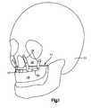
- FIG. 1is a perspective view of a skull with a bone fixation implant affixed to the maxilla;
- FIG. 2Ais a perspective view of a bone fixation implant constructed in accordance with one embodiment
- FIG. 2Bis a front view of the bone fixation implant shown in FIG. 2A ;
- FIG. 2Cis a top view of the bone fixation implant shown in FIG. 2A ;
- FIG. 2Dis a left side view of the bone fixation implant shown in FIG. 2A ;
- FIG. 3Ais a perspective view of an osteotomy guiding implant constructed in accordance with one embodiment
- FIG. 3Bis a front view of the osteotomy guiding implant shown in FIG. 3A ;
- FIG. 3Cis a top view of the osteotomy guiding implant shown in FIG. 3A ;
- FIG. 3Dis a left side view of the osteotomy guiding implant shown in FIG. 3A ;
- FIG. 4is a diagram showing the process for customizing the bone fixation implant of FIGS. 2A-2D and the osteotomy guiding implant of FIGS. 3A-3D to correspond to an individual patient's maxilla;
- FIG. 5Ais a front view of a skull, including a maxilla bone that is to be operated on;
- FIG. 5Bis an enlarged detailed view showing the pre-operative shape of the maxilla of the skull shown in FIG. 5A ;
- FIG. 5Cis a front view of the maxilla shown in FIG. 5B , showing the osteotomy guiding implant of FIGS. 3A-3D being attached to the maxilla;
- FIG. 5Dis a front view of the of the maxilla shown in FIG. 5C , showing holes being drilled into the maxilla through guide holes defined by the osteotomy guiding implant;
- FIG. 5Eis a front view of the maxilla shown in FIG. 5D , showing the drilled holes;
- FIG. 5Fis a front view of the maxilla shown in FIG. 5E , showing the osteotomy performed on the maxilla, using the holes as a cutting guide;
- FIG. 5Gis a front view of the maxilla shown in FIG. 5F , showing a segmented portion of the maxilla being repositioned into a post-operative shape;
- FIG. 5His a front view of the maxilla shown in FIG. 5G , showing the bone fixation implant of FIGS. 2A-2D being attached to the maxilla;
- FIG. 5Iis a front view of the maxilla shown in FIG. 5H , showing the bone fixation implant attached to the maxilla;
- FIG. 5Jis a front view of the maxilla shown in FIG. 5I , showing a bridge portion of the bone fixation implant removed.
- a bone fixation implant 10 to be used in orthognathic surgeryis designed to be fixed to underlying bone such as a patient's skull 12 , and in particular to a patient's maxilla 14 after the maxilla 14 has been separated into a first “segmented” part 18 and a second “integral” part 22 by a segmentation procedure, such as an osteotomy.
- the first part 18 of the maxilla 14typically carries the upper teeth and is completely separated from the skull 12 after the osteotomy has been performed, while the second part 22 of the maxilla 14 remains intact with the skull 12 .
- the bone fixation implant 10is configured to attach to the first and second parts of the maxilla, and thereby support and hold the first part 18 of the maxilla relative to the second part 22 while osteogenesis occurs.
- the implant 10is customized pre-operatively to minimize complications during surgery and time spent in the operating room by a patient.
- the implant 10 and various components of the implantare described herein extending horizontally along a longitudinal direction “L” and lateral direction “A”, and vertically along a transverse direction “T”.
- the terms “lateral,” “longitudinal,” and “transverse”are used to describe the orthogonal directional components of various components.
- the transverse direction Textends vertically generally along the superior-inferior (or caudal-cranial) direction, while the plane defined by the longitudinal direction L and lateral direction A extends horizontally, generally in the anatomical plane defined by the medial-lateral direction and the anterior-posterior direction.
- the directional terms “vertical” and “horizontal”are used to describe the implant 10 and its components as illustrated merely for the purposes of clarity and illustration.
- the bone fixation implant 10includes a longitudinal plate member 30 that is elongate and curved in the longitudinal direction L and a holding structure 34 that extends vertically from the longitudinal member 30 .
- the longitudinal plate member 30includes an upper edge 38 , a bone engaging surface configured to lie substantially flush with the maxilla, and an outer surface opposed to the bone engaging surface. Therefore, the holding structure 34 extends up from the upper edge 38 of the longitudinal member 30 .
- the bone fixation implant 10supports and holds the first part 18 of the maxilla relative to the second part 22 while osteogenesis occurs.
- the bone fixation implant 10 and components thereofcan be formed from a variety of biocompatible materials, such as cobalt chromium molybdenum (CoCrMo), titanium, and titanium alloys, stainless steel, ceramics, or polymers such as polyetheretherketone (PEEK), polyetherketoneketone (PEKK), and bioresorbable materials.
- a coatingmay be added or applied to the bone fixation implant 10 to improve physical or chemical properties or to provide medications. Examples of coatings include plasma-sprayed titanium coating or Hydroxyapatite.
- the longitudinal member 30is configured to be attached to the first part 18 of the maxilla 14 .
- the longitudinal member 30includes a central bridge member 42 that separates the longitudinal member 30 into a first portion 46 and a second portion 50 .
- the first and second portions 46 , 50extend from the bridge member 42 from respective junctions 54 .
- the first portion 46extends from the bridge member 42 in a first direction
- the second portion 50extends from the bridge member 42 in a second direction that is generally opposite to the first direction.
- the first portion 46 and the second portion 50each curves in the lateral direction A as they extend longitudinally. Therefore, as best shown in FIG.
- the longitudinal member 30is curved such that it forms generally a C-shaped structure. Furthermore, as best shown in FIGS. 2B and 2D , the first portion 46 and the second portion 50 each angle up in the transverse direction T as they extend longitudinally. The curvature and shape of the longitudinal member 30 generally correspond to the shape of the maxilla 14 .
- first and second portions 46 , and 50 of the longitudinal member 30include a plurality of fixation element receiving apertures/holes 58 that extend from the outer surface of the longitudinal member 30 and through to the bone engaging surface.
- Each hole 58is configured to receive a fixation element, such as a screw. Though it should be understood that any fixation element will suffice.
- the implant 10is configured to be fastened to the first part 18 of the maxilla 14 by inserting fixation elements through each hole 58 of the longitudinal member 30 and into the first part 18 of the maxilla 14 .
- the bridge member 42 of the longitudinal member 30includes a plate 62 that is elongate in the longitudinal direction L, an extension 66 extending in the lateral direction A from each end of the plate 62 , and a centrally located protrusion 70 that also extends laterally from an inner surface of the plate 62 .
- the junctions 54are located at the posterior ends of each extension 66 .
- the first and second portions 46 , 50 of the longitudinal member 30each extend from a posterior end of a respective extension 66 of the bridge member 42 .
- the bridge member 42may be removed from the longitudinal member 30 at the junctions 54 once the implant 10 is secured to the maxilla 14 .
- junction points 54may be weakened so that the bridge member 42 may be easily removed once the implant 10 is secured to the maxilla 14 .
- junctions 54may be thinned, or perforated, or otherwise configured, so that the bridge member 42 may be removed by snapping the bridge member 42 away. It should be understood however that the bridge member 42 may be removed by cutting the junction points 54 with snips or pliers. Because the bridge member 42 is removable, the amount of the implant 10 left in the patient may be minimized.
- the bridge memberfurther includes a reference hole 74 that extends laterally through both the plate 62 and the protrusion 70 of the bridge member 42 .
- the implant 10may initially be fastened to the maxilla 14 by inserting a fixation element through the reference hole 74 and into the maxilla 14 .
- the fixation element inserted into the reference hole 74may temporarily affix the implant 10 to the maxilla 14 while a surgeon correctly aligns the implant 10 for complete fixation to the maxilla 14 .
- the longitudinal member 30 and in particular the first and second portions 46 , 50is pre-shaped to correspond to the post-operative shape of the first part 18 of the maxilla 14 .
- the longitudinal memberis pre-shaped prior to the segmentation procedure, so as to correspond to an outer surface of the first part of the maxilla after the segmentation procedure.
- the member 30is pre-shaped such that no manual bending is required prior to placement of the implant 10 onto the maxilla 14
- the member 30may be pre-shaped such that only minimal bending is required prior to placement of the implant 10 onto the maxilla 14 (e.g. bending that may take place when fastening the member 30 to the maxilla 14 ). As best shown in FIG.
- the first and second portions 46 , 50include several non-linear undulations 78 that correspond to particular surface portions of the first part 18 of the maxilla 14 . It should be understood, however, that the shape of the first part 18 of the maxilla 14 may be unchanged between the pre-operative and post-operative shape of the maxilla 14 . Therefore, the longitudinal member 30 may be pre-shaped to correspond to both the pre-operative shape and the post-operative shape of the first part 18 of the maxilla 14 .
- the holding structure 34 of the implant 10includes at least one finger 80 , such as a plurality of fingers 80 that extend up from the upper edge 38 of the longitudinal member 30 .
- two fingers 80extend from each of the first and second portions 46 , and 50 of the longitudinal member 30 .
- each finger 80includes at least one fixation element receiving aperture or hole 84 configured to receive a fixation element, such as a screw, so as to affix the fingers 80 to the second part 22 of the maxilla 14 .
- any fixation elementwill suffice. While the embodiment illustrated shows each finger 80 having two holes 84 , it should be understood, that each finger may have any number of holes, e.g. 1, 2, 3, 4, etc.
- the fingers 80are spaced apart along the first and second portions 46 , 50 of the longitudinal member 30 and extend substantially perpendicularly relative to the point on the portions 46 , 50 from where they extend. That is, the longitudinal plate member 30 is non-linear and will define tangents at different points along its edge 38 . Therefore, each finger 80 will extend perpendicular with respect to a tangent taken at the point on the edge 38 from which the finger 80 extends. Though it should be understood that the fingers 80 do not have to extend perpendicularly, and may extend at some angle relative to the longitudinal member 30 .
- each finger 80extends from the longitudinal member 30 such that a fixation element hole 58 of the longitudinal member 30 is aligned with the point at which a respective finger 80 extends from the edge 38 of the longitudinal member 30 , to further improve equal force distribution throughout the implant 10 .
- the holding structure 34 or fingers 80are pre-shaped to correspond to the post-operative shape of the second part 22 of the maxilla 14 , and extend from the first and second portions 46 , 50 , so as to provide a fixation member that corresponds to the shape and the relationship of the first parts of the maxilla.
- the fingers 80are pre-shaped prior to the segmentation procedure, so as to correspond to an outer surface of the second part of the maxilla after the segmentation procedure. While it is preferable that the fingers 30 are pre-shaped such that no manual bending is required prior to placement of the implant 10 onto the maxilla 14 , the fingers 80 may be pre-shaped such that only minimal bending is required prior to placement of the implant 10 onto the maxilla 14 . Therefore, as best shown in FIG.
- the fingers 80include several non-linear undulations 90 that correspond to particular surface portions of the second part 22 of the maxilla 14 . Because the fingers 80 are pre-shaped, they will fit correctly only at the desired location of the maxilla 14 and provide a surgeon with positive assurance that they have achieved correct alignment and, therefore, a desired corrected shape.
- a temporary osteotomy guiding implant 110may be affixed to the maxilla 14 before the osteotomy is performed on the maxilla 14 to create a guide for the surgeon.
- the osteotomy guiding plate 110provides a template for a surgeon to follow while performing the osteotomy.
- the osteotomy guiding implant 110allows the surgeon to make guide holes in the maxilla to follow while performing the osteotomy.
- the osteotomy guiding implantacts as a drill guiding implant.
- the osteotomy guiding implantalso provides a template for the surgeon to follow while implanting the bone implant 10 .
- the osteotomy guiding implant 110is also customized pre-operatively to minimize complications during surgery and time spent in the operating room by a patient.
- the osteotomy guiding implant 110includes a longitudinal plate member 130 that is elongate and curved in the longitudinal direction L, and a template portion 132 that includes a plurality of fingers/protrusions 134 that extend vertically in the transverse direction T from the longitudinal member 130 .
- the osteotomy guiding implant 110includes an upper edge 138 , a bone engaging surface configured to lie substantially flush with the maxilla, and an outer surface opposed to the bone engaging surface.
- the osteotomy guiding implant 110 and components thereofcan be formed from a variety of biocompatible materials, such as cobalt chromium molybdenum (CoCrMo), titanium, and titanium alloys, stainless steel, ceramics, or polymers such as polyetheretherketone (PEEK), polyetherketoneketone (PEKK), and bioresorbable materials.
- a coatingmay be added or applied to the osteotomy guiding implant 110 to improve physical or chemical properties or to provide medications. Examples of coatings include plasma-sprayed titanium coating or Hydroxyapatite.
- the longitudinal plate member 130includes a first portion 146 and a second portion 150 that extend in opposite directions from a central juncture 154 .
- Each portion 146 and 150curves in the lateral direction A as it extends longitudinally. Therefore, as shown in FIG. 3C , the longitudinal member 130 is curved such that it forms generally a C-shaped structure similar to the bone fixation implant 10 .
- the first portion 146 and the second portion 150each angle up in the transverse direction T as they extend longitudinally.
- the curvature and shape of the longitudinal member 130should be configured to correspond to the shape of the maxilla 14 .
- the longitudinal plate member 130further includes a reference hole 174 that extends through the plate member 130 proximate to the central juncture 154 from the outer surface to the bone engaging surface.
- the osteotomy guiding implant 110may initially be fastened to the maxilla 14 by inserting a fixation element through the reference hole 174 and into the maxilla 14 .
- the fixation element inserted into the reference hole 174may be temporary and is utilized while a surgeon correctly aligns the implant 110 so that an osteotomy guide may be created.
- the longitudinal plate member 130defines a plurality of apertures or holes 176 .
- the embodiment illustratedincludes three holes 176 in each portion 146 and 150 .
- the holes 176are spaced apart and provide a template for the surgeon to drill pre-holes into the maxilla 14 that will align with the holes 58 defined by the longitudinal member 30 of the bone implant 10 . Therefore, the surgeon will know where to secure the bone implant 10 to the first part 18 of the maxilla 14 after the osteotomy is performed by aligning the holes 58 of the bone implant 10 with the pre-drilled holes.
- the longitudinal plate member 130does not have the apertures 176 , and thus the pre-drilled holes are not required to properly align the bone implant 10 .
- the osteotomy guiding implant's fingers 134extend up from the upper edge 138 of the longitudinal member 130 .
- two fingers 134extend from each of the first and second portions 146 , and 150 of the longitudinal member 130 .
- any number of fingers 134may extend up from the first and second portions 146 , and 150 .
- the fingers 134are spaced apart along the longitudinal member 130 and extend substantially perpendicularly relative to the point on the longitudinal member 130 from where they extend. That is, the longitudinal member 130 is non-linear and will define tangents at different points along its edge 138 . Therefore, the fingers 134 extend perpendicular with respect to a tangent taken at the point on the edge 138 from which the finger 134 extends. Though it should be understood that the fingers 134 do not have to extend perpendicularly and may extend at an angle relative to the longitudinal member 130 .
- each finger 134 of the osteotomy guiding implant 110defines an aperture or hole 180 .
- the holes 180are configured to receive a drill bit so that guide holes may be drilled into the maxilla 14 to thereby define a guide path along which the osteotomy may be performed.
- the holes 180 of the fingers 134will be positioned such that the guide path along which the osteotomy will be performed is appropriately located so that the bone fixation implant 10 may securely hold the first part 18 of the maxilla 14 relative to the second part 22 . That is, the osteotomy will be located such that the fingers 80 of the bone implant 10 will be long enough to extend across the osteotomy to securely hold the first part 18 of the maxilla relative to the second part 22 .
- the osteotomy guiding implant 110and in particular the longitudinal member 130 and the fingers 134 , is pre-shaped to correspond to the pre-operative shape, and relative position of the first part 18 and the second part 22 of the maxilla 14 .
- the longitudinal member 130 and the fingers 134include several non-linear undulations 190 that correspond to particular portions of the first part 18 and the second part 22 of the maxilla 14 .
- both the bone fixation implant 10 and the osteotomy guiding implant 110are manufactured and shaped pre-operatively.
- a 3-D image of the patient's skull, and in particular the patient's maxilla, such as maxilla 14is obtained.
- Thismay be completed with a CT scanning device 200 or the like, with slices smaller than 1 mm preferred, and optimally between 0.2-1 mm.
- a high resolution for the slicesis preferred, since the exact shape of the maxilla 14 should be determined from the CT scan slices. It will be appreciated that other scanning devices 200 besides a CT scanning device may be used so long as they provide three dimensional data corresponding to the shape of the maxilla 14 .
- the imageis loaded into a computer 204 to create a virtual model of the skull for manipulation by a user such as the surgeon.
- the computer 204may be local (same general area as the CT scanning device 200 ) or remote where the image must be sent via a network.
- the image loaded onto the computer 204may be manipulated by a user that is working locally or remotely. Typically, however, the image is manipulated remotely by the surgeon who will be performing the orthognathic surgery.
- the virtual model of the skullmay be manipulated by the surgeon using standard software typical in the art.
- Mimicsa software commercially available from Materialise, having a place of business in Leuven Belgium, may be used to process and manipulate the virtual model obtained from the CT scanning device 200 .
- the softwareallows the surgeon to analyze the patient's maxilla and pre-operatively plan the patient's orthognathic surgery including the shape and design of the bone fixation implant a and an osteotomy guiding implant.
- the surgeonmay first make a virtual model of an osteotomy guiding implant, such as the osteotomy guiding implant 110 shown in FIGS. 3A-3D . This is accomplished by determining on the virtual model of the skull where the osteotomy is to be performed, and then actually performing a virtual osteotomy on the virtual model. Once the virtual osteotomy is complete, the surgeon can begin making the virtual model of the osteotomy guiding implant 110 . At this point, it should be understood that the virtual model of the skull and in particular the maxilla still has its pre-operative shape and position.
- the longitudinal plate member 130 and the fingers 134 of the osteotomy guiding implant 110 that is being madewill correspond to the pre-operative shape of the patient's maxilla.
- the holes 180 that are formed in the fingers 134 of the osteotomy guiding implant 110will be made in the virtual model to correspond to the virtual osteotomy that was performed on the virtual model of the skull. Therefore, the osteotomy guiding implant 110 manufactured using the virtual model, will define holes 180 that create a guide path for the surgeon to follow while performing the osteotomy. In this way, the actual osteotomy performed on the patient will match the virtual osteotomy that was performed on the virtual model.
- the surgeon or other operatormay manipulate the first part 18 (the cut off portion) of the virtual model of the maxilla 14 from a first undesired position to a second desired position.
- a virtual model of a bone fixation implantsuch as the bone fixation implant 10 shown in FIGS. 2A-2D , can be made.
- the virtual model of the skull and in particular the maxillahas a post-operative shape and position. Therefore, the longitudinal plate member 30 and the fingers 80 of the bone fixation implant 10 that is being made will correspond to the post-operative shape of the patient's maxilla.
- the virtual models of the osteotomy guiding implant 110 and the bone fixation implant 10may be downloaded or transferred from the computer 204 to a CAD/CAM milling machine 220 or the like.
- the milling machine 220will machine the osteotomy guiding implant 110 and the bone fixation implant 10 out of any desired material. Once the osteotomy guiding implant 110 and the bone fixation implant 10 have been manufactured, the surgeon may begin the orthognathic surgery on the patient.
- FIGS. 5A-5Jshow an example method of performing an orthognathic surgery using the osteotomy guiding implant 110 and the bone fixation implant 10 .
- the osteotomy guiding implant 110 and the bone fixation implant 10are pre-shaped to substantially correspond to the individual patient's maxilla.
- FIG. 5Ashows an example skull 12 having a maxilla 14 that needs to be repositioned.
- FIG. 5Bis a detailed view of the maxilla 14 shown in FIG. 5A . As shown, the maxilla 14 at this point has a pre-operative shape.
- An osteotomyis to be performed on the maxilla 14 to thereby separate the maxilla 14 into a first part 18 and a second part 22 , so that the first part 18 can be repositioned, as will be described below.
- the osteotomy guiding implant 110may be placed onto the maxilla 14 .
- the osteotomy guiding implant 110is pre-shaped to correspond to the pre-operative shape of the maxilla 14 , and therefore will lie flush against the maxilla 14 .
- both the longitudinal plate member 130 and the fingers 134will be pre-shaped to correspond to the pre-operative shape of the maxilla 14 .
- the osteotomy guiding implant 110may be temporarily affixed to the maxilla 14 by inserting a screw 300 into the reference hole 174 of the osteotomy guiding implant 110 and screwing it into the maxilla 14 with a driver 300 .
- the surgeonmay then drill holes into the maxilla 14 using a drill bit 304 .
- the drill bit 304may be inserted into the holes 180 defined by the fingers 134 of the osteotomy guiding implant 110 .
- the holes 180are pre-planned and positioned so that the surgeon can create a cutting path for the surgeon to follow while performing the osteotomy.
- four holes 320are drilled into maxilla 14 using the osteotomy guiding implant 110 . While four holes 320 are shown, it should be understood that the osteotomy guiding implant 110 may be configured so that any number of holes 320 may be made using the osteotomy guiding implant 110 .
- the osteotomy guiding implant 110may be made to have six fingers 134 so that six holes 320 may be made in the maxilla.
- drill bit 304 or another drill bitmay be inserted into holes 176 defined by the longitudinal member 130 of the osteotomy guiding implant 110 .
- FIG. 5Esix holes 324 are drilled into the maxilla 14 using the osteotomy guiding implant 110 . While six holes 324 are shown, it should be understood that the osteotomy guiding implant 110 may be configured so that any number of holes 324 may be made using the osteotomy guiding implant 110 .
- the holes 324will act as a guide for the surgeon to properly place the bone implant 10 to the maxilla.
- the holes 324are smaller than the holes 58 defined by the bone implant 10 . Thus when a screw is affixed the threads of the screw will grab a portion of the bone.
- the osteotomy guiding implant 110may be removed and the surgeon may perform an osteotomy 330 on the maxilla 14 along the cutting path created by the holes 320 .
- the cutting pathextends from one hole 320 to an adjacent hole 320 until the osteotomy is complete.
- the osteotomy 330separates the maxilla into a first part 18 and a second part 22 . While the second part 22 remains intact with the skull, the first part 18 is free to be repositioned by the surgeon, for example as shown in FIG. 5G .
- the bone fixation implant 10may be placed onto the maxilla 14 .
- the bone fixation implant 10is pre-shaped to correspond to the post-operative shape of the maxilla 14 , and therefore will lie flush against the maxilla 14 even after the first part 18 of the maxilla 14 has been repositioned.
- both the longitudinal plate member 30 and the fingers 80 of the bone plate 10will be pre-shaped to correspond to the post-operative shape of the maxilla 14 .
- the bone fixation implant 10may be temporarily affixed to the maxilla 14 by inserting a screw into the reference hole 74 of the bone fixation implant 10 and screwing it into the maxilla 14 with the driver 300 . In most cases the reference hole 74 of the bone fixation implant 10 will line up with the hole created in the maxilla 14 by the screw that was used to temporarily affix the osteotomy guiding implant 110 to the maxilla 14 .
- a plurality of screws 340may be inserted into the holes 58 and the holes 84 of the bone fixation implant 10 .
- the fingers 80 of the bone fixation implant 10are affixed to the second part 22 of the maxilla 14 with the screws 340
- the longitudinal member 30 of the bone fixation implant 10is affixed to the first part 18 of the maxilla 14 with the screws 340 . Therefore, the bone fixation implant 10 is affixed to the maxilla 14 on either side of the osteotomy 330 .
- the bridge member 42may then be removed from the bone fixation implant 10 thereby separating the bone fixation implant 10 into two separate parts 350 .
- the bone fixation implant 10may be considered to be a single bone fixation implant 10 that is configured to be separated into two separate implant segments or sections after the bone fixation implant 10 has been affixed to bone.
- the bridge member 42may be removed by either snapping it away or by using pliers or snips to cut the bridge member away at the junctions 54 . It should be understood, however, that the bridge member 42 may be removed using any method known in the art.
- the bone fixation implant 10is completely installed. Therefore, the surgery may be completed, and the implant 10 may either remain within in the patient or be removed at a later time.
- the bone fixation implant 10 and the osteotomy guiding implant 110may be sold separately or as a kit. It should be understood, however, that the osteotomy guiding implant 110 and bone fixation implant 10 may be manufactured and delivered at different times even though they are part of the same kit.
- the kitmay also include all of the fixation elements required to affix the bone fixation implant 10 to the maxilla 14 as well as any tools required to complete the procedure.
- the bone fixation implant 10is shown as having a removable bridge member 42 , it should be understood that the bone fixation implant may remain intact after it has been installed.
- the longitudinal member 30 of the bone fixation implant 10may be a single continuous plate that is configured to remain a single piece after installation of the bone plate 10 .
- the holes 180 of the osteotomy guiding implant 110are positioned in the fingers 134 of the implant 110 such that a guide path is created for the osteotomy to be performed along the holes
- the holes 180may be positioned to create an alternative guide.
- the holes 180may be positioned to create holes in the maxilla 14 that line up with the holes 58 defined by the longitudinal member 30 of the bone fixation implant 10 . In such a case the osteotomy would be performed above the holes 180 .
- the bone fixation implant 10 and the osteotomy guiding implant 110have been described for use in orthognathic surgeries involving the maxilla, it should be understood that the bone fixation implant 10 and the osteotomy guiding implant 110 may be used in orthognathic surgeries involving the mandible.
- the bone fixation implant 10 and the osteotomy guiding implant 110are not limited to orthognathic surgeries and may be utilized in surgeries for other parts of the body that may need to affix a first segmented portion of bone relative to a second integral portion of bone.
Landscapes
- Health & Medical Sciences (AREA)
- Orthopedic Medicine & Surgery (AREA)
- Life Sciences & Earth Sciences (AREA)
- Surgery (AREA)
- General Health & Medical Sciences (AREA)
- Engineering & Computer Science (AREA)
- Veterinary Medicine (AREA)
- Animal Behavior & Ethology (AREA)
- Public Health (AREA)
- Medical Informatics (AREA)
- Molecular Biology (AREA)
- Biomedical Technology (AREA)
- Heart & Thoracic Surgery (AREA)
- Nuclear Medicine, Radiotherapy & Molecular Imaging (AREA)
- Oral & Maxillofacial Surgery (AREA)
- Neurology (AREA)
- Dentistry (AREA)
- Physics & Mathematics (AREA)
- Bioinformatics & Cheminformatics (AREA)
- Epidemiology (AREA)
- Biophysics (AREA)
- Physiology (AREA)
- Bioinformatics & Computational Biology (AREA)
- Biotechnology (AREA)
- Evolutionary Biology (AREA)
- Spectroscopy & Molecular Physics (AREA)
- Theoretical Computer Science (AREA)
- Cardiology (AREA)
- Transplantation (AREA)
- Vascular Medicine (AREA)
- High Energy & Nuclear Physics (AREA)
- Optics & Photonics (AREA)
- Pathology (AREA)
- Radiology & Medical Imaging (AREA)
- Surgical Instruments (AREA)
- Prostheses (AREA)
Abstract
Description
Claims (18)
Priority Applications (23)
| Application Number | Priority Date | Filing Date | Title |
|---|---|---|---|
| US12/770,088US9066733B2 (en) | 2010-04-29 | 2010-04-29 | Orthognathic implant and methods of use |
| ES11713963.4TES2548162T3 (en) | 2010-04-29 | 2011-04-01 | Orthognathic implant |
| PCT/US2011/030885WO2011136898A1 (en) | 2010-04-29 | 2011-04-01 | Orthognathic implant |
| CN201180021403.9ACN102858254B (en) | 2010-04-29 | 2011-04-01 | Orthognathic Implants |
| JP2013507974AJP5951598B2 (en) | 2010-04-29 | 2011-04-01 | Orthognathic implant |
| CA2795724ACA2795724C (en) | 2010-04-29 | 2011-04-01 | Orthognathic implant |
| EP19173047.2AEP3566663B1 (en) | 2010-04-29 | 2011-04-01 | Orthognathic implant |
| US13/078,250US8435270B2 (en) | 2010-04-29 | 2011-04-01 | Orthognathic implant and methods of use |
| CN201510655134.1ACN105147374B (en) | 2010-04-29 | 2011-04-01 | Orthognathic implant |
| EP17185253.6AEP3263050B1 (en) | 2010-04-29 | 2011-04-01 | Orthognathic implant |
| EP15173790.5AEP2952145B2 (en) | 2010-04-29 | 2011-04-01 | Orthognathic implant |
| KR1020127027313AKR101788349B1 (en) | 2010-04-29 | 2011-04-01 | Orthognathic implant |
| EP11713963.4AEP2563242B1 (en) | 2010-04-29 | 2011-04-01 | Orthognathic implant |
| US13/855,802US9277948B2 (en) | 2010-04-29 | 2013-04-03 | Orthognathic implant and methods of use |
| US14/731,587US9381072B2 (en) | 2010-04-29 | 2015-06-05 | Orthognathic implant and methods of use |
| US15/010,553US9855056B2 (en) | 2010-04-29 | 2016-01-29 | Orthognathic implant and methods of use |
| JP2016114692AJP6231616B2 (en) | 2010-04-29 | 2016-06-08 | Orthognathic implant |
| JP2017202904AJP6490776B2 (en) | 2010-04-29 | 2017-10-19 | Orthognathic implant |
| US15/828,568US10080567B2 (en) | 2010-04-29 | 2017-12-01 | Orthognathic implant and method of use |
| US16/114,484US11357514B2 (en) | 2010-04-29 | 2018-08-28 | Orthognathic implant and methods of use |
| JP2019034465AJP6768861B2 (en) | 2010-04-29 | 2019-02-27 | Jaw correction implant |
| JP2020134954AJP7171662B2 (en) | 2010-04-29 | 2020-08-07 | orthodontic implant |
| US17/805,890US12433605B2 (en) | 2010-04-29 | 2022-06-08 | Orthognathic implant and methods of use |
Applications Claiming Priority (1)
| Application Number | Priority Date | Filing Date | Title |
|---|---|---|---|
| US12/770,088US9066733B2 (en) | 2010-04-29 | 2010-04-29 | Orthognathic implant and methods of use |
Related Child Applications (2)
| Application Number | Title | Priority Date | Filing Date |
|---|---|---|---|
| US13/078,250Continuation-In-PartUS8435270B2 (en) | 2010-04-29 | 2011-04-01 | Orthognathic implant and methods of use |
| US14/731,587DivisionUS9381072B2 (en) | 2010-04-29 | 2015-06-05 | Orthognathic implant and methods of use |
Publications (2)
| Publication Number | Publication Date |
|---|---|
| US20110269100A1 US20110269100A1 (en) | 2011-11-03 |
| US9066733B2true US9066733B2 (en) | 2015-06-30 |
Family
ID=43983347
Family Applications (2)
| Application Number | Title | Priority Date | Filing Date |
|---|---|---|---|
| US12/770,088Active2031-06-14US9066733B2 (en) | 2010-04-29 | 2010-04-29 | Orthognathic implant and methods of use |
| US14/731,587ActiveUS9381072B2 (en) | 2010-04-29 | 2015-06-05 | Orthognathic implant and methods of use |
Family Applications After (1)
| Application Number | Title | Priority Date | Filing Date |
|---|---|---|---|
| US14/731,587ActiveUS9381072B2 (en) | 2010-04-29 | 2015-06-05 | Orthognathic implant and methods of use |
Country Status (8)
| Country | Link |
|---|---|
| US (2) | US9066733B2 (en) |
| EP (4) | EP3566663B1 (en) |
| JP (5) | JP5951598B2 (en) |
| KR (1) | KR101788349B1 (en) |
| CN (2) | CN102858254B (en) |
| CA (1) | CA2795724C (en) |
| ES (1) | ES2548162T3 (en) |
| WO (1) | WO2011136898A1 (en) |
Cited By (12)
| Publication number | Priority date | Publication date | Assignee | Title |
|---|---|---|---|---|
| US9381072B2 (en) | 2010-04-29 | 2016-07-05 | DePuy Synthes Products, Inc. | Orthognathic implant and methods of use |
| US20160250001A1 (en)* | 2013-10-29 | 2016-09-01 | Massimo Zanna | Dental Implant |
| US9855056B2 (en) | 2010-04-29 | 2018-01-02 | DePuy Synthes Products, Inc. | Orthognathic implant and methods of use |
| US20180103965A1 (en)* | 2015-05-12 | 2018-04-19 | Karl Leibinger Medizintechnik Gmbh & Co. Kg | Orthognathic saw and positioning implant |
| US10470806B2 (en)* | 2017-02-07 | 2019-11-12 | Kls-Martin, L.P. | Maxillomandibular fixation devices |
| US10595942B2 (en) | 2011-12-14 | 2020-03-24 | Stryker European Holdings I, Llc | Techniques for generating a bone plate design |
| US20200222060A1 (en)* | 2016-05-06 | 2020-07-16 | Karl Leibinger Medizintechnik Gmbh & Co. Kg | Mandibular resection template |
| US10751100B2 (en) | 2014-12-17 | 2020-08-25 | Medartis Holding Ag | Bone screws and surgical sets comprising bone screws |
| US10828068B2 (en) | 2014-12-17 | 2020-11-10 | Medartis Holding Ag | Bone plate, surgical sets and reconstruction sets |
| WO2021086971A1 (en)* | 2019-10-28 | 2021-05-06 | Travis Simpson | Orthognathic surgical implant assembly having pre-osteotomy and post-osteotomy alignment members |
| US20220168028A1 (en)* | 2019-06-07 | 2022-06-02 | Usw Commercial Services Ltd | Support for an anatomical structure |
| US20230056989A1 (en)* | 2021-08-17 | 2023-02-23 | Edward Perez | Bone fixation devices, systems, and methods |
Families Citing this family (129)
| Publication number | Priority date | Publication date | Assignee | Title |
|---|---|---|---|---|
| US8608749B2 (en) | 2006-02-27 | 2013-12-17 | Biomet Manufacturing, Llc | Patient-specific acetabular guides and associated instruments |
| US8535387B2 (en) | 2006-02-27 | 2013-09-17 | Biomet Manufacturing, Llc | Patient-specific tools and implants |
| US8864769B2 (en) | 2006-02-27 | 2014-10-21 | Biomet Manufacturing, Llc | Alignment guides with patient-specific anchoring elements |
| US8858561B2 (en)* | 2006-06-09 | 2014-10-14 | Blomet Manufacturing, LLC | Patient-specific alignment guide |
| US8608748B2 (en) | 2006-02-27 | 2013-12-17 | Biomet Manufacturing, Llc | Patient specific guides |
| US8603180B2 (en) | 2006-02-27 | 2013-12-10 | Biomet Manufacturing, Llc | Patient-specific acetabular alignment guides |
| US8377066B2 (en) | 2006-02-27 | 2013-02-19 | Biomet Manufacturing Corp. | Patient-specific elbow guides and associated methods |
| US20150335438A1 (en) | 2006-02-27 | 2015-11-26 | Biomet Manufacturing, Llc. | Patient-specific augments |
| US9173661B2 (en) | 2006-02-27 | 2015-11-03 | Biomet Manufacturing, Llc | Patient specific alignment guide with cutting surface and laser indicator |
| US9289253B2 (en) | 2006-02-27 | 2016-03-22 | Biomet Manufacturing, Llc | Patient-specific shoulder guide |
| US9907659B2 (en) | 2007-04-17 | 2018-03-06 | Biomet Manufacturing, Llc | Method and apparatus for manufacturing an implant |
| US8568487B2 (en) | 2006-02-27 | 2013-10-29 | Biomet Manufacturing, Llc | Patient-specific hip joint devices |
| US10278711B2 (en) | 2006-02-27 | 2019-05-07 | Biomet Manufacturing, Llc | Patient-specific femoral guide |
| US8407067B2 (en) | 2007-04-17 | 2013-03-26 | Biomet Manufacturing Corp. | Method and apparatus for manufacturing an implant |
| US8133234B2 (en) | 2006-02-27 | 2012-03-13 | Biomet Manufacturing Corp. | Patient specific acetabular guide and method |
| US9918740B2 (en) | 2006-02-27 | 2018-03-20 | Biomet Manufacturing, Llc | Backup surgical instrument system and method |
| US7967868B2 (en) | 2007-04-17 | 2011-06-28 | Biomet Manufacturing Corp. | Patient-modified implant and associated method |
| US8092465B2 (en) | 2006-06-09 | 2012-01-10 | Biomet Manufacturing Corp. | Patient specific knee alignment guide and associated method |
| US8241293B2 (en) | 2006-02-27 | 2012-08-14 | Biomet Manufacturing Corp. | Patient specific high tibia osteotomy |
| US9113971B2 (en) | 2006-02-27 | 2015-08-25 | Biomet Manufacturing, Llc | Femoral acetabular impingement guide |
| US9339278B2 (en) | 2006-02-27 | 2016-05-17 | Biomet Manufacturing, Llc | Patient-specific acetabular guides and associated instruments |
| US8591516B2 (en) | 2006-02-27 | 2013-11-26 | Biomet Manufacturing, Llc | Patient-specific orthopedic instruments |
| US9795399B2 (en) | 2006-06-09 | 2017-10-24 | Biomet Manufacturing, Llc | Patient-specific knee alignment guide and associated method |
| DE102008034300A1 (en)* | 2008-07-23 | 2010-01-28 | Lucas Automotive Gmbh | Vehicle disc brake |
| FR2942125B1 (en)* | 2009-02-17 | 2012-02-17 | Obl | CUSTOM-MADE ASSEMBLY OF AT LEAST TWO OSTEOSYNTHESIS PLATES, THEMSELVES PREPARED TO MEASURE, AND METHOD FOR PLACING THE SAME |
| DE102009028503B4 (en) | 2009-08-13 | 2013-11-14 | Biomet Manufacturing Corp. | Resection template for the resection of bones, method for producing such a resection template and operation set for performing knee joint surgery |
| US8632547B2 (en) | 2010-02-26 | 2014-01-21 | Biomet Sports Medicine, Llc | Patient-specific osteotomy devices and methods |
| US9271744B2 (en) | 2010-09-29 | 2016-03-01 | Biomet Manufacturing, Llc | Patient-specific guide for partial acetabular socket replacement |
| US9968376B2 (en) | 2010-11-29 | 2018-05-15 | Biomet Manufacturing, Llc | Patient-specific orthopedic instruments |
| US9241745B2 (en) | 2011-03-07 | 2016-01-26 | Biomet Manufacturing, Llc | Patient-specific femoral version guide |
| US8715289B2 (en) | 2011-04-15 | 2014-05-06 | Biomet Manufacturing, Llc | Patient-specific numerically controlled instrument |
| US9675400B2 (en) | 2011-04-19 | 2017-06-13 | Biomet Manufacturing, Llc | Patient-specific fracture fixation instrumentation and method |
| US8668700B2 (en) | 2011-04-29 | 2014-03-11 | Biomet Manufacturing, Llc | Patient-specific convertible guides |
| US8956364B2 (en) | 2011-04-29 | 2015-02-17 | Biomet Manufacturing, Llc | Patient-specific partial knee guides and other instruments |
| GB201108078D0 (en)* | 2011-05-16 | 2011-06-29 | Materialise Nv | Surgical guides and methods for manufacturing thereof |
| US8532807B2 (en) | 2011-06-06 | 2013-09-10 | Biomet Manufacturing, Llc | Pre-operative planning and manufacturing method for orthopedic procedure |
| US9084618B2 (en) | 2011-06-13 | 2015-07-21 | Biomet Manufacturing, Llc | Drill guides for confirming alignment of patient-specific alignment guides |
| US20130001121A1 (en) | 2011-07-01 | 2013-01-03 | Biomet Manufacturing Corp. | Backup kit for a patient-specific arthroplasty kit assembly |
| US8764760B2 (en) | 2011-07-01 | 2014-07-01 | Biomet Manufacturing, Llc | Patient-specific bone-cutting guidance instruments and methods |
| US8597365B2 (en) | 2011-08-04 | 2013-12-03 | Biomet Manufacturing, Llc | Patient-specific pelvic implants for acetabular reconstruction |
| US9066734B2 (en)* | 2011-08-31 | 2015-06-30 | Biomet Manufacturing, Llc | Patient-specific sacroiliac guides and associated methods |
| US9295497B2 (en)* | 2011-08-31 | 2016-03-29 | Biomet Manufacturing, Llc | Patient-specific sacroiliac and pedicle guides |
| US9386993B2 (en) | 2011-09-29 | 2016-07-12 | Biomet Manufacturing, Llc | Patient-specific femoroacetabular impingement instruments and methods |
| KR20130046337A (en) | 2011-10-27 | 2013-05-07 | 삼성전자주식회사 | Multi-view device and contol method thereof, display apparatus and contol method thereof, and display system |
| US9554910B2 (en) | 2011-10-27 | 2017-01-31 | Biomet Manufacturing, Llc | Patient-specific glenoid guide and implants |
| US9451973B2 (en) | 2011-10-27 | 2016-09-27 | Biomet Manufacturing, Llc | Patient specific glenoid guide |
| US9301812B2 (en) | 2011-10-27 | 2016-04-05 | Biomet Manufacturing, Llc | Methods for patient-specific shoulder arthroplasty |
| US9237950B2 (en) | 2012-02-02 | 2016-01-19 | Biomet Manufacturing, Llc | Implant with patient-specific porous structure |
| US9361410B2 (en)* | 2012-05-03 | 2016-06-07 | DePuy Synthes Products, Inc. | Surgical guides from scanned implant data |
| US9411939B2 (en) | 2012-09-12 | 2016-08-09 | DePuy Synthes Products, Inc. | Method for producing patient-specific plate |
| US9204977B2 (en) | 2012-12-11 | 2015-12-08 | Biomet Manufacturing, Llc | Patient-specific acetabular guide for anterior approach |
| US9060788B2 (en) | 2012-12-11 | 2015-06-23 | Biomet Manufacturing, Llc | Patient-specific acetabular guide for anterior approach |
| FR2999071A1 (en) | 2012-12-12 | 2014-06-13 | Obl | METHOD FOR REPOSITIONING BONE FRAGMENTS FOR BONE SURGERY BASED ON THE USE OF IMPLANTS AND CUSTOM GUIDES |
| US8920512B2 (en) | 2012-12-19 | 2014-12-30 | Biomet Sports Medicine, Llc | Method and apparatus for pre-forming a high tibial osteotomy |
| JP6356147B2 (en) | 2013-01-04 | 2018-07-11 | デピュイ・シンセス・プロダクツ・インコーポレイテッド | Bone implant design and manufacturing method |
| US9839438B2 (en) | 2013-03-11 | 2017-12-12 | Biomet Manufacturing, Llc | Patient-specific glenoid guide with a reusable guide holder |
| US9579107B2 (en) | 2013-03-12 | 2017-02-28 | Biomet Manufacturing, Llc | Multi-point fit for patient specific guide |
| US9826981B2 (en) | 2013-03-13 | 2017-11-28 | Biomet Manufacturing, Llc | Tangential fit of patient-specific guides |
| US9498233B2 (en) | 2013-03-13 | 2016-11-22 | Biomet Manufacturing, Llc. | Universal acetabular guide and associated hardware |
| US10639129B2 (en) | 2013-03-14 | 2020-05-05 | National Dentex, Llc | Bone foundation guide system and method |
| US10278789B2 (en) | 2013-03-14 | 2019-05-07 | National Dentex, Llc | Bone foundation guide system and method |
| US10398530B2 (en) | 2013-03-14 | 2019-09-03 | National Dentex, Llc | Bone foundation guide system and method |
| US10405945B2 (en) | 2013-03-14 | 2019-09-10 | National Dentex, Llc | Bone foundation guide and method of use |
| US10307226B2 (en) | 2013-03-14 | 2019-06-04 | National Dentex, Llc | Bone foundation guide and method of use |
| US9517145B2 (en) | 2013-03-15 | 2016-12-13 | Biomet Manufacturing, Llc | Guide alignment system and method |
| EP2789308B1 (en)* | 2013-04-12 | 2018-01-31 | CADFEM GmbH | Computer-implemented technique for generating a data set that geometrically defines a bone cut configuration |
| CN103598911A (en)* | 2013-11-21 | 2014-02-26 | 江苏百得医疗器械有限公司 | Craniomaxillofacial bone fracture plate |
| US10531900B2 (en) | 2014-04-17 | 2020-01-14 | Zimmer Biomet CMF and Thoracic, LLC | Contourable plate |
| US10282488B2 (en) | 2014-04-25 | 2019-05-07 | Biomet Manufacturing, Llc | HTO guide with optional guided ACL/PCL tunnels |
| US9408616B2 (en) | 2014-05-12 | 2016-08-09 | Biomet Manufacturing, Llc | Humeral cut guide |
| US9561040B2 (en) | 2014-06-03 | 2017-02-07 | Biomet Manufacturing, Llc | Patient-specific glenoid depth control |
| US9839436B2 (en) | 2014-06-03 | 2017-12-12 | Biomet Manufacturing, Llc | Patient-specific glenoid depth control |
| JP6580667B2 (en)* | 2014-07-09 | 2019-09-25 | デピュイ・シンセス・プロダクツ・インコーポレイテッド | Flexible upper and lower jaw fixation device |
| US20160022385A1 (en)* | 2014-07-28 | 2016-01-28 | Kun Zhao | Dental implant system and method of use |
| WO2016033497A1 (en)* | 2014-08-28 | 2016-03-03 | Nextremity Solutions, Inc. | Proximal bunion resection guides and plates and methods of use |
| KR101668919B1 (en)* | 2014-09-18 | 2016-11-09 | 서울대학교산학협력단 | CAD-CAM based Maxillary Template for Orthognathic Surgery |
| US9833245B2 (en) | 2014-09-29 | 2017-12-05 | Biomet Sports Medicine, Llc | Tibial tubercule osteotomy |
| US9826994B2 (en) | 2014-09-29 | 2017-11-28 | Biomet Manufacturing, Llc | Adjustable glenoid pin insertion guide |
| US9820868B2 (en) | 2015-03-30 | 2017-11-21 | Biomet Manufacturing, Llc | Method and apparatus for a pin apparatus |
| US10449017B2 (en) | 2015-06-08 | 2019-10-22 | Cadskills Bvba | Subperiosteal jaw implant |
| WO2016197328A1 (en)* | 2015-06-09 | 2016-12-15 | 佘承鑫 | Fixing bone plate |
| CN104939936B (en)* | 2015-06-23 | 2017-11-17 | 广州医科大学附属口腔医院 | A kind of micro-implant is implanted into servicing unit |
| US10568647B2 (en) | 2015-06-25 | 2020-02-25 | Biomet Manufacturing, Llc | Patient-specific humeral guide designs |
| US10226262B2 (en) | 2015-06-25 | 2019-03-12 | Biomet Manufacturing, Llc | Patient-specific humeral guide designs |
| KR101686055B1 (en)* | 2015-07-30 | 2016-12-14 | 주식회사 제노스 | Multi drilling guide device for operating implant |
| EP3364908A1 (en) | 2015-10-23 | 2018-08-29 | Daniel R. Llop | Bone foundation guide system and method |
| CN105380708A (en)* | 2015-11-23 | 2016-03-09 | 李焰 | Skeleton fixing plate pre-operation preformation method based on 3D printing model |
| CN105342702B (en)* | 2015-12-17 | 2017-10-13 | 四川大学 | A kind of Individual Mandibular bone fixation guide plate based on 3D printing |
| DE102015122793A1 (en)* | 2015-12-23 | 2017-06-29 | Karl Leibinger Medizintechnik Gmbh & Co. Kg | Implant for bone augmentation with Bohrvektorvorgabeloch and Umgriffsplatte for jaw replacement and Implantatstellverfahren |
| DE102015122800B3 (en)* | 2015-12-23 | 2017-05-11 | Karl Leibinger Medizintechnik Gmbh & Co. Kg | Bone structure adapted molded implant with socket and associated manufacturing process |
| CN105520776A (en)* | 2016-01-20 | 2016-04-27 | 上海景堂医疗器械有限公司 | Four-section type mandible molding plate |
| CA3015801A1 (en) | 2016-03-05 | 2017-09-14 | National Dentex, Llc | Bone foundation guide system and method |
| US10016242B2 (en)* | 2016-06-06 | 2018-07-10 | Neocis Inc. | Splint device for forming a fiducial marker for a surgical robot guidance system, and associated method |
| US10792154B2 (en) | 2016-06-17 | 2020-10-06 | Socovar, L.P. | Limb sparing in mammals using patient-specific endoprostheses and cutting guides |
| CA2969998A1 (en) | 2016-06-17 | 2017-12-17 | Socovar, L.P. | Limb sparing in mammals using patient-specific endoprostheses and cutting guides |
| RU2622030C1 (en)* | 2016-06-23 | 2017-06-08 | федеральное государственное бюджетное образовательное учреждение высшего образования "Ростовский государственный медицинский университет" Министерства здравоохранения Российской Федерации (ФГБОУ ВО РостГМУ Минздрава России) | Method of surgical treatment of fractures of the upper wall of the superstructural fluid |
| CN108606823A (en)* | 2016-12-09 | 2018-10-02 | 深圳市普天阳医疗科技股份有限公司 | A kind of mandibular resetting apparatus and production method |
| US10874404B2 (en) | 2016-12-30 | 2020-12-29 | DePuy Synthes Products, Inc. | Customized patient-specific surgical instruments and method |
| CN108261221B (en)* | 2016-12-30 | 2023-01-10 | 广州迈普再生医学科技股份有限公司 | Mandible cuts bone baffle |
| BR112019015878A2 (en) | 2017-02-06 | 2020-04-14 | Depuy Synthes Products Inc | foldable graft containment cage |
| CA3053415A1 (en)* | 2017-02-17 | 2018-08-23 | Institut National De La Sante Et De La Recherche Medicale (Inserm) | Temporo-mandibular prosthesis |
| US10722310B2 (en) | 2017-03-13 | 2020-07-28 | Zimmer Biomet CMF and Thoracic, LLC | Virtual surgery planning system and method |
| WO2018213817A1 (en) | 2017-05-18 | 2018-11-22 | Jason Watson | Fixation base and guides for dental prosthesis installation |
| WO2019028423A1 (en)* | 2017-08-03 | 2019-02-07 | Johnston Thomas S Jr | Orthognathic implant assembly and method of use |
| DE102017123516A1 (en)* | 2017-10-10 | 2019-04-11 | Karl Leibinger Medizintechnik Gmbh & Co. Kg | Fibula bone removal and disposal template |
| KR101994956B1 (en)* | 2017-11-03 | 2019-07-02 | 애니메디솔루션 주식회사 | Guide for mandible reduction surgery |
| US11154311B2 (en)* | 2017-12-15 | 2021-10-26 | The Catholic University Of Korea Industry-Academic Cooperation Foundation | Customizable surgical bone-cutting jigsaw puzzle-type guide device and customizable surgical bone-cutting guide-traction-suction device |
| US10537343B2 (en) | 2018-01-24 | 2020-01-21 | DePuy Synthes Products, Inc. | Low-profile metallic customized patient-specific orthopaedic surgical instruments |
| US10631878B2 (en) | 2018-01-24 | 2020-04-28 | DePuy Synthes Products, Inc. | Customized patient-specific anterior-posterior chamfer block and method |
| US10716581B2 (en) | 2018-01-24 | 2020-07-21 | DePuy Synthes Products, Inc. | Method of designing and manufacturing low-profile customized patient-specific orthopaedic surgical instruments |
| US11376054B2 (en) | 2018-04-17 | 2022-07-05 | Stryker European Operations Limited | On-demand implant customization in a surgical setting |
| BE1026696A9 (en)* | 2018-10-08 | 2020-05-14 | Tita Link B V B A | Bone anchor for an upper or lower jaw with a corresponding drilling jig |
| KR102198270B1 (en)* | 2018-11-09 | 2021-01-06 | 주식회사 커스메디 | Implant for Restoring and Fixing Maxillofacial defects |
| CN109662770B (en)* | 2019-01-15 | 2024-03-22 | 上海交通大学医学院附属第九人民医院 | Titanium alloy Sandwich bone grafting and fixing titanium plate generated by three-dimensional printing technology |
| CN109620380B (en)* | 2019-01-21 | 2023-08-25 | 四川大学 | A guide plate for reduction and fixation of mandibular double mental foramen fractures |
| CN109820567A (en)* | 2019-03-06 | 2019-05-31 | 上海交通大学医学院附属第九人民医院 | A kind of titanium alloy maxillary alveolar bone osteotomy guide plate that three-dimensional printing technology generates |
| CN110393581B (en)* | 2019-07-09 | 2020-11-20 | 义乌市优创知识产权运营有限公司 | A kind of external fixation bracket for mandibular fracture and its fixation method |
| JP7450845B2 (en)* | 2019-10-04 | 2024-03-18 | ケイエルエス マーティン, エル.ピー. | Surgical guide and implant with alignment member |
| CN112155647B (en)* | 2020-09-29 | 2024-09-13 | 福建医科大学附属第一医院 | Preparation method of operation guide plate for mandibular tumor resection based on occlusion function as guide |
| US12347100B2 (en) | 2020-11-19 | 2025-07-01 | Mazor Robotics Ltd. | Systems and methods for generating virtual images |
| DE102020134236A1 (en) | 2020-12-18 | 2022-06-23 | Karl Leibinger Medizintechnik Gmbh & Co. Kg | Maxillary reduction implant with retaining bracket |
| DE102020134246A1 (en) | 2020-12-18 | 2022-06-23 | Karl Leibinger Medizintechnik Gmbh & Co. Kg | Fingerless Maxillary Reduction Implant |
| DE102020134240A1 (en) | 2020-12-18 | 2022-06-23 | Karl Leibinger Medizintechnik Gmbh & Co. Kg | Diamond-forming maxillary reduction implant |
| TR202022430A1 (en)* | 2020-12-30 | 2022-07-21 | Bezmialem Vakif Ueniversitesi | A SURGICAL PLATE |
| CN112773532B (en)* | 2021-01-26 | 2025-01-28 | 上海交通大学医学院附属第九人民医院 | Bone-supported maxillary posterior long implant implant guide based on 3D printing technology |
| US20220330992A1 (en)* | 2021-04-20 | 2022-10-20 | Travis Simpson | Maxillofacial Fixation Implants Having a Registration Member Relative to the Anterior Nares and Anterior Nasal Spine |
| FR3126298B1 (en)* | 2021-08-31 | 2024-04-12 | Global D | ZYGOMATIC IMPLANT AND CORRESPONDING SURGICAL METHOD |
| CN115770093A (en)* | 2022-12-15 | 2023-03-10 | 江苏双羊医疗器械有限公司 | Locking maxillofacial reconstruction type bone fracture plate |
| TWI835698B (en)* | 2023-08-25 | 2024-03-11 | 陳良誠 | Maxilla holder |
Citations (80)
| Publication number | Priority date | Publication date | Assignee | Title |
|---|---|---|---|---|
| US4484570A (en) | 1980-05-28 | 1984-11-27 | Synthes Ltd. | Device comprising an implant and screws for fastening said implant to a bone, and a device for connecting two separated pieces of bone |
| US4575805A (en) | 1980-12-24 | 1986-03-11 | Moermann Werner H | Method and apparatus for the fabrication of custom-shaped implants |
| EP0290138A2 (en) | 1987-04-07 | 1988-11-09 | POLLOCK, Richard Allison | Method of manufacturing of anatomical precontoured plates |
| US4966599A (en) | 1987-04-07 | 1990-10-30 | Pollock Richard A | Anatomical precontoured plating, instruments and methods |
| US4976737A (en) | 1988-01-19 | 1990-12-11 | Research And Education Institute, Inc. | Bone reconstruction |
| DE4018273A1 (en) | 1989-07-06 | 1991-01-17 | Schwestka Rainer Dr Med Dent | Surgical operation for correction of jaw malformation - is aided by using models of jaw before and after operation |
| US5052930A (en) | 1989-11-22 | 1991-10-01 | Lodde Jean Pierre | Dental implant and method of implantation |
| WO1991014404A1 (en) | 1990-03-21 | 1991-10-03 | Titanbron I Åhus AB | Method and device for efficiently anchoring an implant, and method and device for promoting growth of bone tissue |
| DE9115341U1 (en) | 1991-12-11 | 1992-02-20 | Merten, Hans Albert, Dr.med. Dr.med.dent., 3400 Göttingen | Support grid for receiving particulate bone replacement materials |
| EP0566255A1 (en) | 1992-03-30 | 1993-10-20 | TiMesh, Inc. | Perforated metallic panels and strips for internal fixation of bone fractures and for reconstructive surgery |
| CN2146964Y (en) | 1992-12-31 | 1993-11-24 | 武汉军工总医院 | Separable adjustable external fixer for lower jawbone fracture reduction |
| US5306150A (en) | 1992-08-04 | 1994-04-26 | Gittleman Neal B | Dental ramus implant |
| US5364396A (en) | 1993-03-29 | 1994-11-15 | Robinson Randolph C | Distraction method and apparatus |
| US5373860A (en) | 1992-08-25 | 1994-12-20 | Catone; Guy A. | Apparatus for and method of contouring plates for bone fixation |
| US5452407A (en) | 1992-06-10 | 1995-09-19 | Amei Technologies Inc. | Method for representing a patient's treatment site as data for use with a CAD or CAM device |
| EP0748616A1 (en) | 1994-12-28 | 1996-12-18 | Tsunehisa Shimoda | Dental implant |
| US5622493A (en) | 1994-04-04 | 1997-04-22 | Razdolsky; Yan | Mandibular distration device for use in mandibular distraction osteogenesis |
| WO1997020512A1 (en) | 1995-12-01 | 1997-06-12 | Walker David A | Telescopic bone plate for use in bone lenghtening by distraction osteogenesis |
| JPH09215699A (en) | 1996-02-08 | 1997-08-19 | Nagoya Rashi Seisakusho:Kk | Bone stretcher |
| US5690631A (en)* | 1996-09-11 | 1997-11-25 | Walter Lorenz Surgical, Inc. | Multi-configurable plating system |
| DE19629011A1 (en) | 1996-07-18 | 1998-01-22 | Wolter Dietmar Prof Dr Med | Auxiliary for promoting osteo-synthesis |
| JPH1043203A (en) | 1996-08-07 | 1998-02-17 | Keisei Ika Kogyo Kk | Bone extending device |
| US5769637A (en) | 1996-05-22 | 1998-06-23 | Sofamor Danek Properties, Inc. | Dental implant and alveolar process augmentation structures and method of installation |
| GB2324470A (en) | 1997-04-24 | 1998-10-28 | Customflex Limited | Prosthetic implants |
| US5836948A (en)* | 1997-01-02 | 1998-11-17 | Saint Francis Medical Technologies, Llc | Spine distraction implant and method |
| EP0890345A1 (en) | 1997-07-09 | 1999-01-13 | Holger K. Dr. Essiger | Device for regeneration of human or animal bone, in particular for the jawbone |
| US5885283A (en) | 1992-08-04 | 1999-03-23 | Gittleman; Neal B. | Osteogenic mandibular distention apparatus and method |
| US5895387A (en) | 1996-10-09 | 1999-04-20 | Romulo Guerrero | Method of craniofacial bone distraction |
| WO1999044529A1 (en) | 1998-03-06 | 1999-09-10 | Bionx Implants Oy | Bioabsorbable, deformable fixation plate |
| EP1088520A2 (en) | 1999-09-29 | 2001-04-04 | Yan Razdolsky | Distraction apparatus for the maxilla or mandible |
| WO2001034044A1 (en) | 1999-11-10 | 2001-05-17 | Ulrich Longerich | Bone distractor having a positioning device |
| US6254639B1 (en) | 1996-09-25 | 2001-07-03 | Ninian Peckitt | Prosthetic implants |
| WO2001078612A1 (en) | 2000-04-18 | 2001-10-25 | Walter Lorenz Surgical, Inc. | Resorbable bone distractor and method |
| WO2002028298A1 (en) | 2000-10-04 | 2002-04-11 | Synthes Ag Chur | Maxillary distractor |
| US20020062127A1 (en) | 1998-02-18 | 2002-05-23 | W.L. Lorenz | Method and apparatus for mandibular osteosynthesis |
| US20020116002A1 (en) | 1999-03-23 | 2002-08-22 | Synthes (Usa) | Orthopedic system having detachable bone anchors |
| US20020128654A1 (en) | 1998-02-18 | 2002-09-12 | Steger Shon D. | Method and apparatus for bone fracture fixation |
| US20030105463A1 (en) | 2000-01-17 | 2003-06-05 | Philippe Wolgen | Distraction device for maxillofacial surgery |
| US20030139748A1 (en) | 2001-03-12 | 2003-07-24 | Tomoaki Koseki | Maxillary bone extensor |
| US6712851B1 (en) | 1998-01-23 | 2004-03-30 | Macropore Biosurgery, Inc. | Resorbable, macro-porous non-collapsing and flexible membrane barrier for skeletal repair and regeneration |
| US20040138591A1 (en) | 2001-08-30 | 2004-07-15 | Hiroshi Iseki | Method for modeling an implant and an implant manufactured by the method |
| US20040166469A1 (en) | 2002-01-22 | 2004-08-26 | Tremont Timothy J. | Method and apparatus to assist in orthognathic surgery |
| EP1468656A1 (en) | 2003-04-17 | 2004-10-20 | Stryker Leibinger GmbH & Co. KG | Osteosynthesis device |
| CN2668063Y (en) | 2003-08-04 | 2005-01-05 | 胡敏 | Multipurpose built-in lower jawbone automatic traction skeletonizing device |
| EP1502556A2 (en) | 2003-08-01 | 2005-02-02 | BEGO Semados GmbH | Arrangement for guiding dental implant drills, drill template as well as an implant for retaining the template and method for the manufacturing of this drill template |
| JP2005028046A (en) | 2003-07-11 | 2005-02-03 | Kitakyushu Foundation For The Advancement Of Industry Science & Technology | Bone positioning tool |
| US20050039759A1 (en) | 2002-05-07 | 2005-02-24 | Mauro Joseph V. | Method and device for treatment of temporomandibular dysfunction syndrome and facial/dental deformities |
| US6863694B1 (en) | 2000-07-03 | 2005-03-08 | Osteotech, Inc. | Osteogenic implants derived from bone |
| US20050059864A1 (en) | 2001-12-05 | 2005-03-17 | Ophir Fromovich | Periosteal distraction |
| US20050182408A1 (en) | 1999-05-25 | 2005-08-18 | Medartis Ag | Osteosynthetic bone plate |
| US6932842B1 (en) | 1999-05-11 | 2005-08-23 | 3Di Gmbh | Method for generating patient-specific implants |
| US20050192675A1 (en) | 2004-03-01 | 2005-09-01 | Robinson Dane Q. | Device for use in stimulating bone growth |
| US20050256526A1 (en) | 2004-05-13 | 2005-11-17 | Johnston Thomas S | Bone distractor and method |
| US6972020B1 (en) | 2001-06-01 | 2005-12-06 | New York University | Multi-directional internal distraction osteogenesis device |
| WO2005117760A2 (en) | 2004-06-04 | 2005-12-15 | Synthes (U.S.A.) | Soft tissue spacer |
| US6978188B1 (en) | 2002-09-30 | 2005-12-20 | Medical Modeling, Llc | Method for contouring bone reconstruction plates |
| WO2006020245A2 (en) | 2004-07-19 | 2006-02-23 | Synthes (U.S.A.) | Bone distraction apparatus |
| EP1654994A1 (en) | 2004-11-03 | 2006-05-10 | Walter Lorenz Surgical, Inc. | Method and apparatus for bone fracture fixation |
| US20060116682A1 (en) | 2004-11-18 | 2006-06-01 | Longo Marc N | Surgical implant and methods of making and using the same |
| US20060235408A1 (en) | 2001-11-09 | 2006-10-19 | Wang Robert C | Apparatus and methods for bone fracture fixation |
| US20070043370A1 (en) | 2003-05-07 | 2007-02-22 | Minoru Ueda | Callus elongating/regenerating device |
| CN2902227Y (en) | 2006-04-07 | 2007-05-23 | 昆山市蓝博创伟医疗器械有限公司 | Maxillofacial nearthrosis |
| US20070118243A1 (en) | 2005-10-14 | 2007-05-24 | Vantus Technology Corporation | Personal fit medical implants and orthopedic surgical instruments and methods for making |
| WO2007142743A2 (en) | 2006-06-02 | 2007-12-13 | Porex Surgical, Inc. | Craniofacial implant |
| DE102006043204A1 (en) | 2006-09-11 | 2008-03-27 | Zinser, Jochen Max, Dr. | Method for producing surgical splints, in particular for computer-assisted maxillofacial operations and remodeling osteotomies |
| US20080081315A1 (en) | 2006-09-28 | 2008-04-03 | Kim Samuel S | Dr. Seoung Ho Lee's augmentation plates for stabilizing dental implant fixtures |
| US20080195240A1 (en) | 2007-02-13 | 2008-08-14 | Amanda Martin | Method of designing orthopedic plates and plates made in accordance with the method |
| WO2008112074A2 (en) | 2007-03-12 | 2008-09-18 | Scott Lovald | Osteosynthesis plate, method for customizing same, and method for installing same |
| CN201171708Y (en) | 2007-12-26 | 2008-12-31 | 刘遵望 | Mandible built-in arced pull-type distraction osteogenesis device |
| EP2030596A1 (en) | 2007-08-27 | 2009-03-04 | Medartis AG | Implant for treating bones, method for designing the shape of an implant and support structure for an implant. |
| DE102008017619A1 (en) | 2007-04-05 | 2009-04-09 | Jochem Heibach | Upper jaw bone setting and/or regenerating device, has distance holding element that is brought in interference with shaft-shaped implant, and plug connection realized for connection of distance holding element and implant |
| US20090131944A1 (en) | 2004-05-04 | 2009-05-21 | Synthes (U.S.A.) | Midface distractor |
| CN201341974Y (en) | 2008-12-26 | 2009-11-11 | 马秦 | Mandible regeneration titanium mesh bracket |
| CN101637413A (en) | 2009-08-27 | 2010-02-03 | 北京吉马飞科技发展有限公司 | Maxillary bone repair stent and manufacturing method thereof |
| EP2179701A1 (en) | 2008-10-23 | 2010-04-28 | Stryker Leibinger GmbH & Co. KG | Bone plate for use in a surgical procedure |
| US20110301609A1 (en) | 2009-02-17 | 2011-12-08 | Obl | Customised assembly including at least two osteosynthesis plates which are in turn customised |
| US20120029574A1 (en) | 2010-04-29 | 2012-02-02 | Andre Furrer | Orthognathic implant and methods of use |
| US8177822B2 (en) | 2008-05-05 | 2012-05-15 | Lars G. Tellman | Contoured bone plate for fracture fixation having hook members and drill guide for same |
| US20120150243A9 (en) | 2006-08-31 | 2012-06-14 | Catholic Healthcare West (Chw) | Computerized Planning Tool For Spine Surgery and Method and Device for Creating a Customized Guide for Implantations |
| US20120289965A1 (en) | 2009-12-29 | 2012-11-15 | Frederik Gelaude | Customized surgical guides, methods for manufacturing and uses thereof |
Family Cites Families (12)
| Publication number | Priority date | Publication date | Assignee | Title |
|---|---|---|---|---|
| US3955567A (en) | 1974-11-08 | 1976-05-11 | Stryker Corporation | Bone brace |
| JP3566967B2 (en)* | 1995-07-03 | 2004-09-15 | ジンテーズ アクチエンゲゼルシャフト クール | Bone fragment fixation device |
| US6350265B1 (en)† | 2000-01-13 | 2002-02-26 | Walter Lorenz Surgical, Inc. | Cover for plate for mandibular osteosynthesis |
| US6908469B2 (en)* | 2000-10-04 | 2005-06-21 | Synthes (Usa) | Compact maxillary distractor |
| US7635365B2 (en)† | 2003-08-28 | 2009-12-22 | Ellis Thomas J | Bone plates |
| JP2005270133A (en)* | 2004-03-22 | 2005-10-06 | Techno Network Shikoku Co Ltd | Osteotomy implement |
| GB0414277D0 (en)† | 2004-06-25 | 2004-07-28 | Leuven K U Res & Dev | Orthognatic surgery |
| JP4942066B2 (en)* | 2004-09-16 | 2012-05-30 | 国立大学法人大阪大学 | Byte splint manufacturing method |
| US8253778B2 (en)† | 2008-03-21 | 2012-08-28 | Takahashi Atsushi | Three-dimensional digital magnifier operation supporting system |
| EP2344081B1 (en)† | 2008-08-26 | 2013-01-16 | Boiangiu, Andy | A dental bone implant |
| US9066733B2 (en)* | 2010-04-29 | 2015-06-30 | DePuy Synthes Products, Inc. | Orthognathic implant and methods of use |
| JP6754339B2 (en)* | 2017-08-15 | 2020-09-09 | アオイ電子株式会社 | Thermal head |
- 2010
- 2010-04-29USUS12/770,088patent/US9066733B2/enactiveActive
- 2011
- 2011-04-01CNCN201180021403.9Apatent/CN102858254B/enactiveActive
- 2011-04-01KRKR1020127027313Apatent/KR101788349B1/enactiveActive
- 2011-04-01EPEP19173047.2Apatent/EP3566663B1/enactiveActive
- 2011-04-01EPEP17185253.6Apatent/EP3263050B1/enactiveActive
- 2011-04-01WOPCT/US2011/030885patent/WO2011136898A1/enactiveApplication Filing
- 2011-04-01JPJP2013507974Apatent/JP5951598B2/enactiveActive
- 2011-04-01EPEP11713963.4Apatent/EP2563242B1/enactiveActive
- 2011-04-01CACA2795724Apatent/CA2795724C/enactiveActive
- 2011-04-01EPEP15173790.5Apatent/EP2952145B2/enactiveActive
- 2011-04-01ESES11713963.4Tpatent/ES2548162T3/enactiveActive
- 2011-04-01CNCN201510655134.1Apatent/CN105147374B/enactiveActive
- 2015
- 2015-06-05USUS14/731,587patent/US9381072B2/enactiveActive
- 2016
- 2016-06-08JPJP2016114692Apatent/JP6231616B2/enactiveActive
- 2017
- 2017-10-19JPJP2017202904Apatent/JP6490776B2/enactiveActive
- 2019
- 2019-02-27JPJP2019034465Apatent/JP6768861B2/enactiveActive
- 2020
- 2020-08-07JPJP2020134954Apatent/JP7171662B2/enactiveActive
Patent Citations (82)
| Publication number | Priority date | Publication date | Assignee | Title |
|---|---|---|---|---|
| US4484570A (en) | 1980-05-28 | 1984-11-27 | Synthes Ltd. | Device comprising an implant and screws for fastening said implant to a bone, and a device for connecting two separated pieces of bone |
| US4575805A (en) | 1980-12-24 | 1986-03-11 | Moermann Werner H | Method and apparatus for the fabrication of custom-shaped implants |
| EP0290138A2 (en) | 1987-04-07 | 1988-11-09 | POLLOCK, Richard Allison | Method of manufacturing of anatomical precontoured plates |
| US4966599A (en) | 1987-04-07 | 1990-10-30 | Pollock Richard A | Anatomical precontoured plating, instruments and methods |
| US4976737A (en) | 1988-01-19 | 1990-12-11 | Research And Education Institute, Inc. | Bone reconstruction |
| DE4018273A1 (en) | 1989-07-06 | 1991-01-17 | Schwestka Rainer Dr Med Dent | Surgical operation for correction of jaw malformation - is aided by using models of jaw before and after operation |
| US5052930A (en) | 1989-11-22 | 1991-10-01 | Lodde Jean Pierre | Dental implant and method of implantation |
| WO1991014404A1 (en) | 1990-03-21 | 1991-10-03 | Titanbron I Åhus AB | Method and device for efficiently anchoring an implant, and method and device for promoting growth of bone tissue |
| DE9115341U1 (en) | 1991-12-11 | 1992-02-20 | Merten, Hans Albert, Dr.med. Dr.med.dent., 3400 Göttingen | Support grid for receiving particulate bone replacement materials |
| EP0566255A1 (en) | 1992-03-30 | 1993-10-20 | TiMesh, Inc. | Perforated metallic panels and strips for internal fixation of bone fractures and for reconstructive surgery |
| US5452407A (en) | 1992-06-10 | 1995-09-19 | Amei Technologies Inc. | Method for representing a patient's treatment site as data for use with a CAD or CAM device |
| US5885283A (en) | 1992-08-04 | 1999-03-23 | Gittleman; Neal B. | Osteogenic mandibular distention apparatus and method |
| US5306150A (en) | 1992-08-04 | 1994-04-26 | Gittleman Neal B | Dental ramus implant |
| US5373860A (en) | 1992-08-25 | 1994-12-20 | Catone; Guy A. | Apparatus for and method of contouring plates for bone fixation |
| CN2146964Y (en) | 1992-12-31 | 1993-11-24 | 武汉军工总医院 | Separable adjustable external fixer for lower jawbone fracture reduction |
| US5364396A (en) | 1993-03-29 | 1994-11-15 | Robinson Randolph C | Distraction method and apparatus |
| US5622493A (en) | 1994-04-04 | 1997-04-22 | Razdolsky; Yan | Mandibular distration device for use in mandibular distraction osteogenesis |
| EP0748616A1 (en) | 1994-12-28 | 1996-12-18 | Tsunehisa Shimoda | Dental implant |
| WO1997020512A1 (en) | 1995-12-01 | 1997-06-12 | Walker David A | Telescopic bone plate for use in bone lenghtening by distraction osteogenesis |
| JPH09215699A (en) | 1996-02-08 | 1997-08-19 | Nagoya Rashi Seisakusho:Kk | Bone stretcher |
| US5769637A (en) | 1996-05-22 | 1998-06-23 | Sofamor Danek Properties, Inc. | Dental implant and alveolar process augmentation structures and method of installation |
| DE19629011A1 (en) | 1996-07-18 | 1998-01-22 | Wolter Dietmar Prof Dr Med | Auxiliary for promoting osteo-synthesis |
| JPH1043203A (en) | 1996-08-07 | 1998-02-17 | Keisei Ika Kogyo Kk | Bone extending device |
| US5690631A (en)* | 1996-09-11 | 1997-11-25 | Walter Lorenz Surgical, Inc. | Multi-configurable plating system |
| US6254639B1 (en) | 1996-09-25 | 2001-07-03 | Ninian Peckitt | Prosthetic implants |
| US5895387A (en) | 1996-10-09 | 1999-04-20 | Romulo Guerrero | Method of craniofacial bone distraction |
| US5836948A (en)* | 1997-01-02 | 1998-11-17 | Saint Francis Medical Technologies, Llc | Spine distraction implant and method |
| GB2324470A (en) | 1997-04-24 | 1998-10-28 | Customflex Limited | Prosthetic implants |
| EP0890345A1 (en) | 1997-07-09 | 1999-01-13 | Holger K. Dr. Essiger | Device for regeneration of human or animal bone, in particular for the jawbone |
| US7172422B1 (en) | 1997-07-09 | 2007-02-06 | Holger K. Essiger | Device for regenerating, repairing, and modeling human and animal bone, especially the jaw area for dental applications |
| US6712851B1 (en) | 1998-01-23 | 2004-03-30 | Macropore Biosurgery, Inc. | Resorbable, macro-porous non-collapsing and flexible membrane barrier for skeletal repair and regeneration |
| US20020062127A1 (en) | 1998-02-18 | 2002-05-23 | W.L. Lorenz | Method and apparatus for mandibular osteosynthesis |
| US20020128654A1 (en) | 1998-02-18 | 2002-09-12 | Steger Shon D. | Method and apparatus for bone fracture fixation |
| WO1999044529A1 (en) | 1998-03-06 | 1999-09-10 | Bionx Implants Oy | Bioabsorbable, deformable fixation plate |
| US6221075B1 (en)* | 1998-03-06 | 2001-04-24 | Bionx Implants Oy | Bioabsorbable, deformable fixation plate |
| US20020116002A1 (en) | 1999-03-23 | 2002-08-22 | Synthes (Usa) | Orthopedic system having detachable bone anchors |
| US6932842B1 (en) | 1999-05-11 | 2005-08-23 | 3Di Gmbh | Method for generating patient-specific implants |
| US20050182408A1 (en) | 1999-05-25 | 2005-08-18 | Medartis Ag | Osteosynthetic bone plate |
| EP1088520A2 (en) | 1999-09-29 | 2001-04-04 | Yan Razdolsky | Distraction apparatus for the maxilla or mandible |
| WO2001034044A1 (en) | 1999-11-10 | 2001-05-17 | Ulrich Longerich | Bone distractor having a positioning device |
| US20030105463A1 (en) | 2000-01-17 | 2003-06-05 | Philippe Wolgen | Distraction device for maxillofacial surgery |
| WO2001078612A1 (en) | 2000-04-18 | 2001-10-25 | Walter Lorenz Surgical, Inc. | Resorbable bone distractor and method |
| US6863694B1 (en) | 2000-07-03 | 2005-03-08 | Osteotech, Inc. | Osteogenic implants derived from bone |
| WO2002028298A1 (en) | 2000-10-04 | 2002-04-11 | Synthes Ag Chur | Maxillary distractor |
| US20030139748A1 (en) | 2001-03-12 | 2003-07-24 | Tomoaki Koseki | Maxillary bone extensor |
| US6972020B1 (en) | 2001-06-01 | 2005-12-06 | New York University | Multi-directional internal distraction osteogenesis device |
| US20040138591A1 (en) | 2001-08-30 | 2004-07-15 | Hiroshi Iseki | Method for modeling an implant and an implant manufactured by the method |
| US20060235408A1 (en) | 2001-11-09 | 2006-10-19 | Wang Robert C | Apparatus and methods for bone fracture fixation |
| US20050059864A1 (en) | 2001-12-05 | 2005-03-17 | Ophir Fromovich | Periosteal distraction |
| US20040166469A1 (en) | 2002-01-22 | 2004-08-26 | Tremont Timothy J. | Method and apparatus to assist in orthognathic surgery |
| US20050039759A1 (en) | 2002-05-07 | 2005-02-24 | Mauro Joseph V. | Method and device for treatment of temporomandibular dysfunction syndrome and facial/dental deformities |
| US6978188B1 (en) | 2002-09-30 | 2005-12-20 | Medical Modeling, Llc | Method for contouring bone reconstruction plates |
| EP1468656A1 (en) | 2003-04-17 | 2004-10-20 | Stryker Leibinger GmbH & Co. KG | Osteosynthesis device |
| US20070043370A1 (en) | 2003-05-07 | 2007-02-22 | Minoru Ueda | Callus elongating/regenerating device |
| JP2005028046A (en) | 2003-07-11 | 2005-02-03 | Kitakyushu Foundation For The Advancement Of Industry Science & Technology | Bone positioning tool |
| EP1502556A2 (en) | 2003-08-01 | 2005-02-02 | BEGO Semados GmbH | Arrangement for guiding dental implant drills, drill template as well as an implant for retaining the template and method for the manufacturing of this drill template |
| CN2668063Y (en) | 2003-08-04 | 2005-01-05 | 胡敏 | Multipurpose built-in lower jawbone automatic traction skeletonizing device |
| US20050192675A1 (en) | 2004-03-01 | 2005-09-01 | Robinson Dane Q. | Device for use in stimulating bone growth |
| US20090131944A1 (en) | 2004-05-04 | 2009-05-21 | Synthes (U.S.A.) | Midface distractor |
| US20050256526A1 (en) | 2004-05-13 | 2005-11-17 | Johnston Thomas S | Bone distractor and method |
| WO2005117760A2 (en) | 2004-06-04 | 2005-12-15 | Synthes (U.S.A.) | Soft tissue spacer |
| WO2006020245A2 (en) | 2004-07-19 | 2006-02-23 | Synthes (U.S.A.) | Bone distraction apparatus |
| EP1654994A1 (en) | 2004-11-03 | 2006-05-10 | Walter Lorenz Surgical, Inc. | Method and apparatus for bone fracture fixation |
| US20060116682A1 (en) | 2004-11-18 | 2006-06-01 | Longo Marc N | Surgical implant and methods of making and using the same |
| US20070118243A1 (en) | 2005-10-14 | 2007-05-24 | Vantus Technology Corporation | Personal fit medical implants and orthopedic surgical instruments and methods for making |
| CN2902227Y (en) | 2006-04-07 | 2007-05-23 | 昆山市蓝博创伟医疗器械有限公司 | Maxillofacial nearthrosis |
| WO2007142743A2 (en) | 2006-06-02 | 2007-12-13 | Porex Surgical, Inc. | Craniofacial implant |
| US20120150243A9 (en) | 2006-08-31 | 2012-06-14 | Catholic Healthcare West (Chw) | Computerized Planning Tool For Spine Surgery and Method and Device for Creating a Customized Guide for Implantations |
| DE102006043204A1 (en) | 2006-09-11 | 2008-03-27 | Zinser, Jochen Max, Dr. | Method for producing surgical splints, in particular for computer-assisted maxillofacial operations and remodeling osteotomies |
| US20080081315A1 (en) | 2006-09-28 | 2008-04-03 | Kim Samuel S | Dr. Seoung Ho Lee's augmentation plates for stabilizing dental implant fixtures |
| US20080195240A1 (en) | 2007-02-13 | 2008-08-14 | Amanda Martin | Method of designing orthopedic plates and plates made in accordance with the method |
| WO2008112074A2 (en) | 2007-03-12 | 2008-09-18 | Scott Lovald | Osteosynthesis plate, method for customizing same, and method for installing same |
| DE102008017619A1 (en) | 2007-04-05 | 2009-04-09 | Jochem Heibach | Upper jaw bone setting and/or regenerating device, has distance holding element that is brought in interference with shaft-shaped implant, and plug connection realized for connection of distance holding element and implant |
| EP2030596A1 (en) | 2007-08-27 | 2009-03-04 | Medartis AG | Implant for treating bones, method for designing the shape of an implant and support structure for an implant. |
| CN201171708Y (en) | 2007-12-26 | 2008-12-31 | 刘遵望 | Mandible built-in arced pull-type distraction osteogenesis device |
| US8177822B2 (en) | 2008-05-05 | 2012-05-15 | Lars G. Tellman | Contoured bone plate for fracture fixation having hook members and drill guide for same |
| EP2179701A1 (en) | 2008-10-23 | 2010-04-28 | Stryker Leibinger GmbH & Co. KG | Bone plate for use in a surgical procedure |
| CN201341974Y (en) | 2008-12-26 | 2009-11-11 | 马秦 | Mandible regeneration titanium mesh bracket |
| US20110301609A1 (en) | 2009-02-17 | 2011-12-08 | Obl | Customised assembly including at least two osteosynthesis plates which are in turn customised |
| CN101637413A (en) | 2009-08-27 | 2010-02-03 | 北京吉马飞科技发展有限公司 | Maxillary bone repair stent and manufacturing method thereof |
| US20120289965A1 (en) | 2009-12-29 | 2012-11-15 | Frederik Gelaude | Customized surgical guides, methods for manufacturing and uses thereof |
| US20120029574A1 (en) | 2010-04-29 | 2012-02-02 | Andre Furrer | Orthognathic implant and methods of use |
Non-Patent Citations (3)
| Title |
|---|
| International Patent Application No. PCT/US2010/032908: International Search Report dated Nov. 29, 2010, 7 pages. |
| International Patent Application No. PCT/US2011/030885: International Search Report dated Nov. 29, 2010, 7 pages. |
| U.S. Appl. No. 13/078,250, filed Apr. 1, 2011, Andre Furrer. |
Cited By (21)
| Publication number | Priority date | Publication date | Assignee | Title |
|---|---|---|---|---|
| US11357514B2 (en) | 2010-04-29 | 2022-06-14 | DePuy Synthes Products, Inc. | Orthognathic implant and methods of use |
| US9855056B2 (en) | 2010-04-29 | 2018-01-02 | DePuy Synthes Products, Inc. | Orthognathic implant and methods of use |
| US10080567B2 (en) | 2010-04-29 | 2018-09-25 | DePuy Synthes Products, Inc. | Orthognathic implant and method of use |
| US12433605B2 (en) | 2010-04-29 | 2025-10-07 | DePuy Synthes Products, Inc. | Orthognathic implant and methods of use |
| US9381072B2 (en) | 2010-04-29 | 2016-07-05 | DePuy Synthes Products, Inc. | Orthognathic implant and methods of use |
| US11717349B2 (en) | 2011-12-14 | 2023-08-08 | Stryker European Operations Holdings Llc | Technique for generating a bone plate design |
| US10595942B2 (en) | 2011-12-14 | 2020-03-24 | Stryker European Holdings I, Llc | Techniques for generating a bone plate design |
| US10610299B2 (en) | 2011-12-14 | 2020-04-07 | Stryker European Holdings I, Llc | Technique for generating a bone plate design |
| US20160250001A1 (en)* | 2013-10-29 | 2016-09-01 | Massimo Zanna | Dental Implant |
| US10751100B2 (en) | 2014-12-17 | 2020-08-25 | Medartis Holding Ag | Bone screws and surgical sets comprising bone screws |
| US11839409B2 (en) | 2014-12-17 | 2023-12-12 | Medartis Holding Ag | Bone plate, surgical sets and reconstruction sets |
| US10828068B2 (en) | 2014-12-17 | 2020-11-10 | Medartis Holding Ag | Bone plate, surgical sets and reconstruction sets |
| US10932832B2 (en)* | 2015-05-12 | 2021-03-02 | Karl Leibinger Medizintechnik Gmbh & Co. Kg | Orthognathic saw and positioning implant |
| US20180103965A1 (en)* | 2015-05-12 | 2018-04-19 | Karl Leibinger Medizintechnik Gmbh & Co. Kg | Orthognathic saw and positioning implant |
| US10786293B2 (en)* | 2016-05-06 | 2020-09-29 | Karl Leibinger Medizintechnik Gmbh & Co. Kg | Mandibular resection template |
| US20200222060A1 (en)* | 2016-05-06 | 2020-07-16 | Karl Leibinger Medizintechnik Gmbh & Co. Kg | Mandibular resection template |
| US10470806B2 (en)* | 2017-02-07 | 2019-11-12 | Kls-Martin, L.P. | Maxillomandibular fixation devices |
| US20220168028A1 (en)* | 2019-06-07 | 2022-06-02 | Usw Commercial Services Ltd | Support for an anatomical structure |
| WO2021086971A1 (en)* | 2019-10-28 | 2021-05-06 | Travis Simpson | Orthognathic surgical implant assembly having pre-osteotomy and post-osteotomy alignment members |
| US11896273B2 (en) | 2019-10-28 | 2024-02-13 | Kls Martin, L.P. | Orthognathic surgical implant assembly having pre-osteotomy and post-osteotomy alignment members |
| US20230056989A1 (en)* | 2021-08-17 | 2023-02-23 | Edward Perez | Bone fixation devices, systems, and methods |
Also Published As
| Publication number | Publication date |
|---|---|
| ES2548162T3 (en) | 2015-10-14 |
| EP3566663A2 (en) | 2019-11-13 |
| JP5951598B2 (en) | 2016-07-13 |
| CN102858254B (en) | 2015-11-25 |
| JP2013524995A (en) | 2013-06-20 |
| KR101788349B1 (en) | 2017-10-19 |
| US20110269100A1 (en) | 2011-11-03 |
| CA2795724C (en) | 2021-02-23 |
| EP2563242A1 (en) | 2013-03-06 |
| JP6768861B2 (en) | 2020-10-14 |
| JP2018023835A (en) | 2018-02-15 |
| KR20130069575A (en) | 2013-06-26 |
| EP3263050B1 (en) | 2019-05-22 |
| CN105147374A (en) | 2015-12-16 |
| US9381072B2 (en) | 2016-07-05 |
| EP3566663A3 (en) | 2020-02-19 |
| EP3566663B1 (en) | 2022-12-14 |
| US20150265378A1 (en) | 2015-09-24 |
| CA2795724A1 (en) | 2011-11-03 |
| CN102858254A (en) | 2013-01-02 |
| EP2952145B1 (en) | 2017-09-20 |
| JP2020192346A (en) | 2020-12-03 |
| JP6231616B2 (en) | 2017-11-15 |
| WO2011136898A1 (en) | 2011-11-03 |
| JP6490776B2 (en) | 2019-03-27 |
| EP2952145A1 (en) | 2015-12-09 |
| EP3263050A1 (en) | 2018-01-03 |
| JP2019122784A (en) | 2019-07-25 |
| CN105147374B (en) | 2018-01-23 |
| JP7171662B2 (en) | 2022-11-15 |
| JP2016185341A (en) | 2016-10-27 |
| EP2563242B1 (en) | 2015-07-01 |
| EP2952145B2 (en) | 2020-07-15 |
Similar Documents
| Publication | Publication Date | Title |
|---|---|---|
| US12433605B2 (en) | Orthognathic implant and methods of use | |
| US9066733B2 (en) | Orthognathic implant and methods of use | |
| CA2795668C (en) | Orthognathic implant and methods of use | |
| EP2687168B1 (en) | Orthognatic implant |
Legal Events
| Date | Code | Title | Description |
|---|---|---|---|
| AS | Assignment | Owner name:SYNTHES GMBH, SWITZERLAND Free format text:ASSIGNMENT OF ASSIGNORS INTEREST;ASSIGNORS:FURRER, ANDRE;ZILLIG, TIMO;METZGER, MARC CHRISTIAN;SIGNING DATES FROM 20100531 TO 20100618;REEL/FRAME:024863/0256 Owner name:SYNTHES USA, LLC, PENNSYLVANIA Free format text:ASSIGNMENT OF ASSIGNORS INTEREST;ASSIGNOR:SYNTHES GMBH;REEL/FRAME:024863/0298 Effective date:20100715 | |
| AS | Assignment | Owner name:DEPUY SYNTHES PRODUCTS, LLC, MASSACHUSETTS Free format text:CHANGE OF NAME;ASSIGNOR:HAND INNOVATIONS LLC;REEL/FRAME:030359/0036 Effective date:20121231 Owner name:HAND INNOVATIONS LLC, FLORIDA Free format text:ASSIGNMENT OF ASSIGNORS INTEREST;ASSIGNOR:DEPUY SPINE, LLC;REEL/FRAME:030359/0001 Effective date:20121230 Owner name:DEPUY SPINE, LLC, MASSACHUSETTS Free format text:ASSIGNMENT OF ASSIGNORS INTEREST;ASSIGNOR:SYNTHES USA, LLC;REEL/FRAME:030358/0945 Effective date:20121230 | |
| AS | Assignment | Owner name:DEPUY SYNTHES PRODUCTS, INC., MASSACHUSETTS Free format text:CHANGE OF NAME;ASSIGNOR:DEPUY SYNTHES PRODUCTS, LLC;REEL/FRAME:035074/0647 Effective date:20141219 | |
| STCF | Information on status: patent grant | Free format text:PATENTED CASE | |
| AS | Assignment | Owner name:HAND INNOVATIONS LLC, FLORIDA Free format text:CORRECTIVE ASSIGNMENT TO CORRECT THE INCORRECT APPL. NO. 13/486,591 PREVIOUSLY RECORDED AT REEL: 030359 FRAME: 0001. ASSIGNOR(S) HEREBY CONFIRMS THE ASSIGNMENT;ASSIGNOR:DEPUY SPINE, LLC;REEL/FRAME:042621/0565 Effective date:20121230 | |
| AS | Assignment | Owner name:DEPUY SPINE, LLC, MASSACHUSETTS Free format text:CORRECTIVE ASSIGNMENT TO CORRECT THE INCORRECT APPLICATION NO. US 13/486,591 PREVIOUSLY RECORDED ON REEL 030358 FRAME 0945. ASSIGNOR(S) HEREBY CONFIRMS THE ASSIGNMENT;ASSIGNOR:SYNTHES USA, LLC;REEL/FRAME:042687/0849 Effective date:20121230 | |
| MAFP | Maintenance fee payment | Free format text:PAYMENT OF MAINTENANCE FEE, 4TH YEAR, LARGE ENTITY (ORIGINAL EVENT CODE: M1551); ENTITY STATUS OF PATENT OWNER: LARGE ENTITY Year of fee payment:4 | |
| MAFP | Maintenance fee payment | Free format text:PAYMENT OF MAINTENANCE FEE, 8TH YEAR, LARGE ENTITY (ORIGINAL EVENT CODE: M1552); ENTITY STATUS OF PATENT OWNER: LARGE ENTITY Year of fee payment:8 |