US9066701B1 - Systems and methods for performing neurophysiologic monitoring during spine surgery - Google Patents
Systems and methods for performing neurophysiologic monitoring during spine surgeryDownload PDFInfo
- Publication number
- US9066701B1 US9066701B1US13/761,098US201313761098AUS9066701B1US 9066701 B1US9066701 B1US 9066701B1US 201313761098 AUS201313761098 AUS 201313761098AUS 9066701 B1US9066701 B1US 9066701B1
- Authority
- US
- United States
- Prior art keywords
- retractor
- electrode
- blade
- retractor blade
- tissue
- Prior art date
- Legal status (The legal status is an assumption and is not a legal conclusion. Google has not performed a legal analysis and makes no representation as to the accuracy of the status listed.)
- Active, expires
Links
- 230000001537neural effectEffects0.000titleclaimsabstractdescription40
- 238000001356surgical procedureMethods0.000titleclaimsabstractdescription35
- 238000000034methodMethods0.000titleclaimsdescription28
- 238000012544monitoring processMethods0.000titleabstractdescription33
- 230000036541healthEffects0.000claimsabstractdescription13
- 230000000638stimulationEffects0.000claimsdescription63
- 230000004044responseEffects0.000claimsdescription30
- 210000003099femoral nerveAnatomy0.000claimsdescription21
- 210000003041ligamentAnatomy0.000claimsdescription11
- 230000003447ipsilateral effectEffects0.000claimsdescription9
- 230000000763evoking effectEffects0.000claimsdescription6
- 230000001965increasing effectEffects0.000claimsdescription6
- 210000004705lumbosacral regionAnatomy0.000claimsdescription6
- 230000002232neuromuscularEffects0.000claims2
- 238000012360testing methodMethods0.000abstractdescription8
- 230000000926neurological effectEffects0.000abstract1
- 210000001519tissueAnatomy0.000description86
- 210000005036nerveAnatomy0.000description81
- 239000011248coating agentSubstances0.000description12
- 238000000576coating methodMethods0.000description12
- 230000008878couplingEffects0.000description10
- 238000010168coupling processMethods0.000description10
- 238000005859coupling reactionMethods0.000description10
- 239000000463materialSubstances0.000description10
- 230000037361pathwayEffects0.000description10
- 238000013459approachMethods0.000description8
- 230000000694effectsEffects0.000description8
- 230000006870functionEffects0.000description7
- 230000004936stimulating effectEffects0.000description7
- 238000004891communicationMethods0.000description6
- 239000004020conductorSubstances0.000description6
- 230000010339dilationEffects0.000description6
- 230000007246mechanismEffects0.000description6
- RYGMFSIKBFXOCR-UHFFFAOYSA-NCopperChemical compound[Cu]RYGMFSIKBFXOCR-UHFFFAOYSA-N0.000description5
- 230000004888barrier functionEffects0.000description5
- 229910052802copperInorganic materials0.000description5
- 239000010949copperSubstances0.000description5
- 230000006735deficitEffects0.000description5
- 238000012423maintenanceMethods0.000description5
- 210000003205muscleAnatomy0.000description5
- 210000000944nerve tissueAnatomy0.000description5
- 229920000052poly(p-xylylene)Polymers0.000description5
- 229910052709silverInorganic materials0.000description5
- 239000004332silverSubstances0.000description5
- 229910052782aluminiumInorganic materials0.000description4
- XAGFODPZIPBFFR-UHFFFAOYSA-NaluminiumChemical compound[Al]XAGFODPZIPBFFR-UHFFFAOYSA-N0.000description4
- 238000005452bendingMethods0.000description4
- 230000008901benefitEffects0.000description4
- 230000000916dilatatory effectEffects0.000description4
- 238000003780insertionMethods0.000description4
- 230000037431insertionEffects0.000description4
- 239000002991molded plasticSubstances0.000description4
- 229920000049Carbon (fiber)Polymers0.000description3
- 239000004606Fillers/ExtendersSubstances0.000description3
- RTAQQCXQSZGOHL-UHFFFAOYSA-NTitaniumChemical compound[Ti]RTAQQCXQSZGOHL-UHFFFAOYSA-N0.000description3
- 230000002159abnormal effectEffects0.000description3
- 210000000988bone and boneAnatomy0.000description3
- 239000004917carbon fiberSubstances0.000description3
- 230000006835compressionEffects0.000description3
- 238000007906compressionMethods0.000description3
- 208000037265diseases, disorders, signs and symptomsDiseases0.000description3
- 238000006073displacement reactionMethods0.000description3
- 239000007943implantSubstances0.000description3
- 238000007373indentationMethods0.000description3
- 239000004417polycarbonateSubstances0.000description3
- 229920000515polycarbonatePolymers0.000description3
- 230000001681protective effectEffects0.000description3
- 239000000523sampleSubstances0.000description3
- 230000001953sensory effectEffects0.000description3
- 239000010936titaniumSubstances0.000description3
- 229910052719titaniumInorganic materials0.000description3
- 230000000007visual effectEffects0.000description3
- 239000004696Poly ether ether ketoneSubstances0.000description2
- 230000000712assemblyEffects0.000description2
- 238000000429assemblyMethods0.000description2
- JUPQTSLXMOCDHR-UHFFFAOYSA-Nbenzene-1,4-diol;bis(4-fluorophenyl)methanoneChemical compoundOC1=CC=C(O)C=C1.C1=CC(F)=CC=C1C(=O)C1=CC=C(F)C=C1JUPQTSLXMOCDHR-UHFFFAOYSA-N0.000description2
- 150000001875compoundsChemical class0.000description2
- 238000011161developmentMethods0.000description2
- 238000010586diagramMethods0.000description2
- 208000035475disorderDiseases0.000description2
- VNWKTOKETHGBQD-UHFFFAOYSA-NmethaneChemical compoundCVNWKTOKETHGBQD-UHFFFAOYSA-N0.000description2
- 230000005012migrationEffects0.000description2
- 238000013508migrationMethods0.000description2
- 238000012986modificationMethods0.000description2
- 230000004048modificationEffects0.000description2
- 230000007170pathologyEffects0.000description2
- 229920002530polyetherether ketonePolymers0.000description2
- 229920000642polymerPolymers0.000description2
- 230000008569processEffects0.000description2
- 238000012545processingMethods0.000description2
- 210000000278spinal cordAnatomy0.000description2
- 210000000115thoracic cavityAnatomy0.000description2
- 210000005166vasculatureAnatomy0.000description2
- VRBFTYUMFJWSJY-UHFFFAOYSA-N28804-46-8Chemical compoundClC1CC(C=C2)=CC=C2C(Cl)CC2=CC=C1C=C2VRBFTYUMFJWSJY-UHFFFAOYSA-N0.000description1
- 208000003618Intervertebral Disc DisplacementDiseases0.000description1
- 206010061246Intervertebral disc degenerationDiseases0.000description1
- 206010023509KyphosisDiseases0.000description1
- 208000007623LordosisDiseases0.000description1
- 230000005856abnormalityEffects0.000description1
- 230000003213activating effectEffects0.000description1
- 238000004873anchoringMethods0.000description1
- 230000015556catabolic processEffects0.000description1
- 210000002808connective tissueAnatomy0.000description1
- 238000010276constructionMethods0.000description1
- 230000001054cortical effectEffects0.000description1
- 230000003247decreasing effectEffects0.000description1
- 208000018180degenerative disc diseaseDiseases0.000description1
- 238000006731degradation reactionMethods0.000description1
- 238000001514detection methodMethods0.000description1
- 230000003292diminished effectEffects0.000description1
- 201000010099diseaseDiseases0.000description1
- 238000004070electrodepositionMethods0.000description1
- 230000003628erosive effectEffects0.000description1
- 239000011521glassSubstances0.000description1
- 238000003384imaging methodMethods0.000description1
- 230000000977initiatory effectEffects0.000description1
- 208000014674injuryDiseases0.000description1
- 208000021600intervertebral disc degenerative diseaseDiseases0.000description1
- 230000004807localizationEffects0.000description1
- 238000004519manufacturing processMethods0.000description1
- 229910052751metalInorganic materials0.000description1
- 239000002184metalSubstances0.000description1
- 238000012806monitoring deviceMethods0.000description1
- 230000008035nerve activityEffects0.000description1
- 230000036403neuro physiologyEffects0.000description1
- 239000000615nonconductorSubstances0.000description1
- 239000002245particleSubstances0.000description1
- 239000004033plasticSubstances0.000description1
- 210000002097psoas muscleAnatomy0.000description1
- 238000011084recoveryMethods0.000description1
- 238000009877renderingMethods0.000description1
- 210000000574retroperitoneal spaceAnatomy0.000description1
- 206010039722scoliosisDiseases0.000description1
- 238000004904shorteningMethods0.000description1
- 210000004872soft tissueAnatomy0.000description1
- 206010041569spinal fractureDiseases0.000description1
- 210000001032spinal nerveAnatomy0.000description1
- 239000000126substanceSubstances0.000description1
- 239000011573trace mineralSubstances0.000description1
- 235000013619trace mineralNutrition0.000description1
- 230000007704transitionEffects0.000description1
- 230000008733traumaEffects0.000description1
- 239000011800void materialSubstances0.000description1
Images


Classifications
- A—HUMAN NECESSITIES
- A61—MEDICAL OR VETERINARY SCIENCE; HYGIENE
- A61B—DIAGNOSIS; SURGERY; IDENTIFICATION
- A61B1/00—Instruments for performing medical examinations of the interior of cavities or tubes of the body by visual or photographical inspection, e.g. endoscopes; Illuminating arrangements therefor
- A61B1/32—Devices for opening or enlarging the visual field, e.g. of a tube of the body
- A—HUMAN NECESSITIES
- A61—MEDICAL OR VETERINARY SCIENCE; HYGIENE
- A61B—DIAGNOSIS; SURGERY; IDENTIFICATION
- A61B17/00—Surgical instruments, devices or methods
- A61B17/02—Surgical instruments, devices or methods for holding wounds open, e.g. retractors; Tractors
- A61B17/0206—Surgical instruments, devices or methods for holding wounds open, e.g. retractors; Tractors with antagonistic arms as supports for retractor elements
- A—HUMAN NECESSITIES
- A61—MEDICAL OR VETERINARY SCIENCE; HYGIENE
- A61B—DIAGNOSIS; SURGERY; IDENTIFICATION
- A61B90/00—Instruments, implements or accessories specially adapted for surgery or diagnosis and not covered by any of the groups A61B1/00 - A61B50/00, e.g. for luxation treatment or for protecting wound edges
- A61B90/30—Devices for illuminating a surgical field, the devices having an interrelation with other surgical devices or with a surgical procedure
- A—HUMAN NECESSITIES
- A61—MEDICAL OR VETERINARY SCIENCE; HYGIENE
- A61B—DIAGNOSIS; SURGERY; IDENTIFICATION
- A61B17/00—Surgical instruments, devices or methods
- A61B2017/00017—Electrical control of surgical instruments
- A61B2017/00022—Sensing or detecting at the treatment site
- A—HUMAN NECESSITIES
- A61—MEDICAL OR VETERINARY SCIENCE; HYGIENE
- A61B—DIAGNOSIS; SURGERY; IDENTIFICATION
- A61B17/00—Surgical instruments, devices or methods
- A61B2017/00017—Electrical control of surgical instruments
- A61B2017/00022—Sensing or detecting at the treatment site
- A61B2017/00039—Electric or electromagnetic phenomena other than conductivity, e.g. capacity, inductivity, Hall effect
- A—HUMAN NECESSITIES
- A61—MEDICAL OR VETERINARY SCIENCE; HYGIENE
- A61B—DIAGNOSIS; SURGERY; IDENTIFICATION
- A61B17/00—Surgical instruments, devices or methods
- A61B2017/00017—Electrical control of surgical instruments
- A61B2017/00115—Electrical control of surgical instruments with audible or visual output
- A—HUMAN NECESSITIES
- A61—MEDICAL OR VETERINARY SCIENCE; HYGIENE
- A61B—DIAGNOSIS; SURGERY; IDENTIFICATION
- A61B17/00—Surgical instruments, devices or methods
- A61B2017/00017—Electrical control of surgical instruments
- A61B2017/00199—Electrical control of surgical instruments with a console, e.g. a control panel with a display
- A—HUMAN NECESSITIES
- A61—MEDICAL OR VETERINARY SCIENCE; HYGIENE
- A61B—DIAGNOSIS; SURGERY; IDENTIFICATION
- A61B17/00—Surgical instruments, devices or methods
- A61B2017/00017—Electrical control of surgical instruments
- A61B2017/00225—Systems for controlling multiple different instruments, e.g. microsurgical systems
- A—HUMAN NECESSITIES
- A61—MEDICAL OR VETERINARY SCIENCE; HYGIENE
- A61B—DIAGNOSIS; SURGERY; IDENTIFICATION
- A61B34/00—Computer-aided surgery; Manipulators or robots specially adapted for use in surgery
- A61B34/25—User interfaces for surgical systems
Definitions
- This disclosurerelates to a surgical retraction system and related instrumentation and methods for accessing a surgical target site for the purpose of performing surgical procedures.
- the spinal columnis a highly complex system of bones and connective tissues that provide support for the body and protect the delicate spinal cord and nerves.
- the spinal columnincludes a series of vertebral bodies stacked one atop the other, each vertebral body including an inner or central portion of relatively weak cancellous bone and an outer portion of relatively strong cortical bone. Situated between each vertebral body is an intervertebral disc that cushions and dampens compressive forces exerted upon the spinal column.
- a vertebral canal containing the spinal cordis located behind the vertebral bodies.
- spinal column disordersincluding scoliosis (abnormal lateral curvature of the spine), excess kyphosis (abnormal forward curvature of the spine), excess lordosis (abnormal backward curvature of the spine), spondylothesis (forward displacement of one vertebra over another), and other disorders caused by abnormalities, disease or trauma, such as ruptured or slipped discs, degenerative disc disease, fractured vertebra and the like. Patients that suffer from such conditions usually experience extreme and debilitating pain, as well as diminished nerve function.
- Open surgical techniquesare generally undesirable in that they typically require large incisions and high amounts of tissue displacement to gain access to the surgical target site, which produces concomitantly high amounts of pain, lengthened hospitalization (increasing health care costs), and high morbidity in the patient population.
- Less-invasive surgical techniquesincluding so-called “minimal access” and “minimally invasive” techniques are gaining favor due to the fact that they involve accessing the surgical target site via incisions of substantially smaller size with greatly reduced tissue displacement requirements. This, in turn, reduces the pain, morbidity, and cost associated with such procedures.
- the surgical access systemmay include a sequential dilation assembly of increasing diameter and a tissue retraction assembly.
- the sequential dilation assemblyis advanced to the target site first and the retractor assembly is then advanced to the target site over the sequential dilation system.
- Stimulating electrodesmay be provided on the distal tip of one or more of the different components of the surgical access system. Nerve monitoring may be performed while advancing one or more components of the dilation and retraction assemblies to the target site to detect the presence of, and thereby avoid, nerves lying in the trans-psoas path to the target site.
- a nerve situated near any location along the length of a retractor blademight come into inadvertent contact with the blade which could cause the nerve to become compressed over the course of the surgical procedure.
- information regarding the depth, proximity, health, and status of nearby nerves during maintenance of a lateral access corridoris desirable. Because an at-risk nerve may not be in close proximity to the stimulating electrode on the distal tip of the retractor blade, large amounts of stimulation current could be required to depolarize the nerve and elicit a response though it is generally preferable to conduct the monitoring with the least intense stimulation necessary.
- a nerveis compressed, the closer the stimulation signal is delivered to the nerve the more precise information regarding the health and/or status of the nerve is likely to be. Furthermore, information regarding the depth of a nerve during maintenance of the lateral access corridor is also desirable, because it provides specific information as to the site of possible compression relative to the blade. Information regarding the status of the femoral nerve is also difficult to obtain because it is largely a sensory nerve.
- the present disclosureaccomplishes this goal by providing a novel access system and related methods which involve detecting the existence of (and optionally the distance and/or direction to) neural structures before, during, and after the establishment of an operative corridor through (or near) any of a variety of tissues having such neural structures which, if contacted or impinged, may otherwise result in neural impairment for the patient. It is expressly noted that, although described herein largely in terms of use in spinal surgery, the access system of the present disclosure is suitable for use in any number of additional surgical procedures wherein tissue having significant neural structures must be passed through (or near) in order to establish an operative corridor.
- the access system of the present disclosuremay be employed in any number of other spine surgery access approaches, including but not limited to posterior, postero-lateral, anterior, and antero-lateral access, and may be employed in the lumbar, thoracic and/or cervical spine, all without departing from the present disclosure.
- the access systemcomprises a tissue distraction assembly and a tissue retraction assembly, both of which may be equipped with one or more electrodes for use in detecting the existence of (and optionally the distance and/or direction to) neural structures.
- the tissue distraction assembly(in conjunction with one or more elements of the tissue retraction assembly) is capable of, as an initial step, distracting a region of tissue between the skin of the patient and the surgical target site.
- the tissue retraction assemblyis capable of, as a secondary step, being introduced into this distracted region to thereby define and establish the operative corridor. Once established, any of a variety of surgical instruments, devices, or implants may be passed through and/or manipulated within the operative corridor depending upon the given surgical procedure.
- the electrode(s)are capable of, during both tissue distraction and retraction, detecting the existence of (and optionally the distance and/or direction to) neural structures such that the operative corridor may be established through (or near) any of a variety of tissues having such neural structures which, if contacted or impinged, may otherwise result in neural impairment for the patient.
- the access system of the present disclosuremay be used to traverse tissue that would ordinarily be deemed unsafe or undesirable, thereby broadening the number of manners in which a given surgical target site may be accessed.
- the tissue distraction assemblymay include any number of components capable of performing the necessary distraction.
- the tissue distraction assemblymay include a K-wire and one or more dilators (e.g., sequentially dilating cannulae) for performing the necessary tissue distraction to receive the remainder of the tissue retractor assembly thereafter.
- One or more electrodesmay be provided on one or more of the K-wire and dilator(s) to detect the presence of (and optionally the distance and/or direction to) neural structures during tissue distraction.
- the tissue retraction assemblymay include any number of components capable of performing the necessary retraction.
- the tissue retraction assemblymay include one or more retractor blades extending from a handle assembly.
- the handle assemblymay be manipulated to open the retractor assembly; that is, allowing the retractor blades to separate from one another (simultaneously or sequentially) to create an operative corridor to the surgical target site. In a preferred embodiment, this is accomplished by maintaining a posterior retractor blade in a fixed position relative to the surgical target site (so as to avoid having it impinge upon any exiting nerve roots near the posterior elements of the spine) while the additional retractor blades (i.e.
- cephalad-most and caudal-most bladesare moved or otherwise translated away from the posterior retractor blade (and each other) so as to create the operative corridor in a fashion that doesn't impinge upon the region of the exiting nerve roots.
- the cephalad-most and/or caudal-most bladesmay pivot or rotate outward from a central axis of insertion, such that the operative corridor may be further expanded.
- the retractormay include a locking element to maintain the blades in an initial alignment during insertion, and a variable-stop mechanism to allow the user to control the degree of expansion of the operative corridor.
- a blade expander toolmay be provided to facilitate manual pivoting of the retractor blades.
- the retractor bladesmay be optionally dimensioned to receive and direct a locking shim element to augment the structural stability of the retractor blades and thereby ensure the operative corridor, once established, will not decrease or become more restricted, such as may result if distal ends of the retractor blades were permitted to “slide” or otherwise move in response to the force exerted by the displaced tissue.
- only the posterior retractor bladeis equipped with such a rigid shim element.
- this shim elementmay be advanced into the disc space after the posterior retractor blade is positioned, but before the retractor is opened into the fully retracted position.
- the rigid shim elementis preferably oriented within the disc space such that is distracts the adjacent vertebral bodies, which serves to restore disc height. It also preferably advances a sufficient distance within the disc space (preferably past the midline), which advantageously forms a protective barrier that prevents the migration of tissue (such as nerve roots) into the operative field and the inadvertent advancement of instruments outside the operative field.
- the caudal-most and/or cephalad-most bladesmay be fitted with any number of retractor extenders for extending (laterally or length-wise) the blades, which advantageously forms a protective barrier that prevents the migration of tissue (such as muscle and soft tissue) into the operative field and the inadvertent advancement of instruments outside the operative field.
- the retractor bladesmay optionally be equipped with a mechanism for transporting or emitting light at or near the surgical target site to aid the surgeon's ability to visualize the surgical target site, instruments and/or implants during the given surgical procedure.
- this mechanismmay comprise, but need not be limited to, coupling one or more light sources to the retractor blades such that the terminal ends are capable of emitting light at or near the surgical target site.
- this mechanismmay comprise, but need not be limited to, constructing the retractor blades of suitable material (such as clear polycarbonate) and configuration such that light may be transmitted generally distally through the walls of the retractor blade light to shine light at or near the surgical target site.
- Thismay be performed by providing the retractor blades having light-transmission characteristics (such as with clear polycarbonate construction) and transmitting the light almost entirely within the walls of the retractor blade (such as by frosting or otherwise rendering opaque portions of the exterior and/or interior) until it exits a portion along the interior (or medially-facing) surface of the retractor blade to shine at or near the surgical target site.
- the exit portionmay be optimally configured such that the light is directed towards the approximate center of the surgical target site and may be provided along the entire inner periphery of the retractor blade or one or more portions therealong.
- a neuromonitoring systemsuch as the one shown and described in the above-mentioned '045 patent (incorporated by reference) may perform nerve proximity testing on one or more nerves of interest to ensure safe and reproducible access to a surgical target site and maintenance of the lateral access corridor.
- the depth of a nerve of interest relative to a component of the surgical access assemblyis localized, preferably prior to retraction of tissue from the lateral access corridor.
- the nerve of interestis stimulated at a location distal to the site of retraction and a response is recorded from a location proximal to the site of retraction.
- neurophysiologic responses across the site of retractionare recorded at multiple time points during a surgical procedure and are compared to previous responses. Changes in the neurophysiologic responses over time may provide useful information as to the health and status of the nerve.
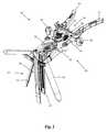
- FIG. 1is a perspective view of one example of a tissue retraction assembly forming part of a surgical access system according to one embodiment of the present disclosure, shown in a fully retracted or “open” position;
- FIG. 2is a perspective view of the tissue retraction assembly of FIG. 1 shown in a fully closed position
- FIG. 3is a perspective view of the tissue retraction assembly of FIG. 1 shown in a partially open position according to the present disclosure
- FIGS. 4-5are front perspective and back perspective views, respectively, of one example of a locking shim forming part of the surgical access system of the present disclosure
- FIG. 6is a top view of the locking shim of FIG. 4 ;
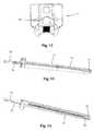
- FIG. 7is a side plan view of a tissue distraction assembly (comprising a plurality of dilating cannulae over a K-wire) used to distract tissue between the skin of the patient and the surgical target site according to one embodiment of the present disclosure;
- FIGS. 8-9are side and perspective views, respectively, of an example of a disposable electrode forming part of the tissue retraction system of FIG. 1 according to one embodiment of the present disclosure
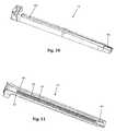
- FIGS. 10-11are perspective views of an example of a retractor blade forming part of the tissue retraction system of FIG. 1 configured to releasably couple with the disposable electrode of FIG. 9 ;
- FIG. 12is top perspective view of the retractor blade of FIG. 10 ;
- FIGS. 13-14are perspective views of an assembly comprising the disposable electrode of FIG. 8 coupled to the retractor blade of FIG. 10 ;
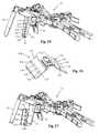
- FIGS. 15-16are perspective views of the tissue retraction assembly of FIG. 1 including the disposable electrode/blade assembly of FIG. 13 ;
- FIGS. 17-18are perspective views of an example of an insulated locking shim for use with the posterior blade forming part of the tissue retraction system of FIG. 1 to prevent current shunting from the posterior blade when neurophysiologic monitoring is performed from the posterior blade;
- FIGS. 19-20are perspective views of an alternative example of an electrode body with multiple electrode contacts at the distal end removeably coupled to a retractor blade, forming part of the tissue retraction system of FIG. 1 ;
- FIGS. 21-24are perspective views of another alternative example of an electrode body with a single electrode at the distal end that is moveable within, and removeably couplable to, a retractor blade, forming part of the tissue retraction system of FIG. 1 ;
- FIG. 25is a perspective view of an example of a retractor blade having multiple electrode contacts at the distal end, forming part of the tissue retraction system of FIG. 1 ;
- FIG. 26is a perspective view of an example of a posterior shim element having multiple electrode contacts, the posterior shim element couplable to a retractor blade forming part of the tissue distraction system of FIG. 1 ;
- FIG. 27is a perspective view of the posterior shim element of FIG. 26 coupled with a retractor blade forming part of the tissue distraction system of FIG. 1 ;
- FIGS. 28-29are perspective views of one example of a locking intradiscal shim having electrode contacts are the distal end and coupled to a retractor blade forming part of the tissue retraction system of FIG. 1 ;
- FIG. 30is a perspective view of an example of a nerve monitoring system programmed to perform nerve monitoring before, during and after the creation of an operative corridor to a surgical target site using the surgical access system of FIG. 1 in accordance with the present disclosure
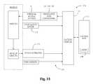
- FIG. 31is a block diagram of the nerve monitoring system shown in FIG. 30 ;
- FIGS. 32-33are examples of screen displays illustrating exemplary features and information communicated to a user during the use of the nerve monitoring system of FIG. 30 ;
- FIG. 34illustrates an example of a first configuration for performing neurophysiologic monitoring of a nerve across a site of retraction to evaluate the health and status of the nerve for possible compression according to one embodiment
- FIG. 35illustrates an example of a second configuration for performing neurophysiologic monitoring of a nerve across a site of retraction to evaluate the health and status of the nerve for possible compression according to one embodiment.
- the access system of the present disclosuremay be employed in any number of other spine surgery access approaches, including but not limited to posterior, postero-lateral, anterior, and antero-lateral access, and may be employed in the lumbar, thoracic and/or cervical spine, all without departing from the present disclosure.
- the surgical access system disclosed hereinboasts a variety of inventive features and components that warrant patent protection, both individually and in combination.
- the present disclosureinvolves accessing a surgical target site in a fashion less invasive than traditional “open” surgeries and doing so in a manner that provides access in spite of the neural structures required to be passed through (or near) in order to establish an operative corridor to the surgical target site.
- the surgical access system of the present disclosureaccomplishes this by providing a tissue distraction assembly and a tissue retraction assembly, both of which may be equipped with one or more electrodes for use in detecting the existence of (and optionally the distance and/or direction to) neural structures.
- Electrodesare preferably provided for use with a nerve surveillance system such as, by way of example, the type shown and described in the above referenced '045 patent.
- this nerve surveillance systemis capable of detecting the existence of (and optionally the distance and/or direction to) neural structures during the distraction and retraction of tissue by detecting the presence of nerves by applying a stimulation signal to such instruments and monitoring the evoked EMG signals from the myotomes associated with the nerves being passed by the distraction and retraction systems of the present disclosure.
- the system as a wholemay be used to form an operative corridor through (or near) any of a variety of tissues having such neural structures, particularly those which, if contacted or impinged, may otherwise result in neural impairment for the patient.
- the access system of the present disclosuremay be used to traverse tissue that would ordinarily be deemed unsafe or undesirable, thereby broadening the number of manners in which a given surgical target site may be accessed.
- the neuromonitoring systemmay perform neuromonitoring as the retractor assembly is used to maintain the lateral access corridor as the target site is operated on. Such monitoring may be used to localize the depth of the nearby nerves relative to the length of a one or more blade and monitor the health and status of the nerves in closest proximity to that blade (or blades).
- the retraction assembly of the surgical access systemmay be configured to: (1) localize the depth of nearby neural structures relative to one or more of the blades; (2) optimize a stimulating and/or recording location relative to one or more of the blades; (3) perform evoked EMG monitoring on the nerve or nerves in closest proximity to the blades; and (4) perform evoked sensory monitoring on the nerves in closest proximity to the blades.
- the tissue distraction assembly of the present disclosureincluding a plurality of sequential dilators and a k-wire, is employed to distract the tissues extending between the skin of the patient and a given surgical target site (preferably along the posterior region of the target intervertebral disc). Once distracted, the resulting void or distracted region within the patient is of sufficient size to accommodate a tissue retraction assembly of the present disclosure. More specifically, the tissue retraction assembly (comprising a plurality of retractor blades extending from a handle assembly) may be advanced, with the blades in a first generally closed position, over the exterior of the outer dilator. At that point, the handle assembly may be operated to move the retractor blades into a second, open or “retracted” position to create an operative corridor to the surgical target site.
- a posterior shim element(which is preferably slidably engaged with the posterior retractor blade) may be advanced such that a distal shim extension is positioned within the posterior region of the disc space. If done before retraction, this helps ensure that the posterior retractor blade will not move posteriorly during the retraction process, even though the other retractor blades (e.g. cephalad-most and caudal-most) are able to move and thereby create an operative corridor. Fixing the posterior retractor blade in this fashion serves several important functions. First, the distal end of the shim element serves to distract the adjacent vertebral bodies, thereby restoring disc height.
- the posterior shim elementalso helps ensure that surgical instruments employed within the operative corridor are incapable of being advanced outside the operative corridor, preventing inadvertent contact with the exiting nerve roots during the surgery.
- the cephalad-most and caudal-most retractor bladesmay be locked in position and, thereafter, retractor extenders advanced therealong to prevent the ingress or egress of instruments or biological structures (e.g. nerves, vasculature, etc.) into or out of the operative corridor.
- the cephalad-most and/or caudal-most retractor bladesmay be pivoted in an outward direction to further expand the operative corridor.
- FIGS. 1-3illustrate a tissue retraction assembly 10 forming part of a surgical access system according to the present disclosure, including a plurality of retractor blades 12 , 16 , 18 extending from a handle assembly 20 .
- the handle assembly 20is provided with a first retractor blade 12 , a second retractor blade 16 , and a third retractor blade 18 .
- FIG. 1illustrates the tissue retraction assembly 10 in a fully retracted or “open” configuration, with the retractor blades 12 , 16 , 18 positioned a distance from one another so as to form an operative corridor 15 therebetween which extends to a surgical target site (e.g. an annulus of an intervertebral disc).
- a surgical target sitee.g. an annulus of an intervertebral disc
- the blades 16 , 18are capable of being pivoted or rotated relative to the handle 20 , as best appreciated with combined reference to FIGS. 1 & 2 .
- FIG. 2shows the tissue retraction assembly 10 in an initial “closed” configuration, with the retractor blades 12 , 16 , 18 generally abutting one another.
- FIG. 3shows the tissue retraction assembly 10 in a “partially open” configuration.
- tissue retraction assembly 10 of the present disclosuremay find use in any number of different surgical approaches, including generally posterior, generally postero-lateral, generally anterior and generally antero-lateral.
- the handle assembly 20may be coupled to any number of mechanisms for rigidly registering the handle assembly 20 in fixed relation to the operative site, such as through the use of an articulating arm mounted to the operating table (not shown).
- the handle assembly 20includes first and second arm members 26 , 28 hingedly coupled via coupling mechanism shown generally at 30 .
- the second retractor blade 16is rigidly coupled (generally perpendicularly) to the end of the first arm member 26 .
- the third retractor blade 18is rigidly coupled (generally perpendicularly) to the end of the second arm member 28 .
- the first retractor blade 12is rigidly coupled (generally perpendicularly to) a translating member 17 , which is coupled to the handle assembly 20 via a linkage assembly shown generally at 14 .
- the linkage assembly 14includes a roller member 34 having a pair of manual knob members 36 which, when rotated via manual actuation by a user, causes teeth 35 on the roller member 34 to engage within ratchet-like grooves 37 in the translating member 17 .
- manual operation of the knobs 36causes the translating member 17 to move relative to the first and second arm members 26 , 28 .
- the arms 26 , 28may be simultaneously opened such that the second and third retractor blades 16 , 18 move away from one another.
- the dimension and/or shape of the operative corridor 15may be tailored depending upon the degree to which the translating member 17 is manipulated relative to the arms 26 , 28 . That is, the operative corridor 15 may be tailored to provide any number of suitable cross-sectional shapes, including but not limited to a generally circular cross-section, a generally ellipsoidal cross-section, a generally triangular cross-section, and/or an oval cross-section.
- Optional light emitting devicesmay be coupled to one or more of the retractor blades 12 , 16 , 18 to direct light down the operative corridor 15 .
- the retractor blades 12 , 16 , 18may be composed of any material suitable for introduction into the human body, including but not limited to aluminum, titanium, and/or clear polycarbonate, that would ensure rigidity during tissue distraction.
- the retractor blades 12 , 16 , 18may be optionally coated with a carbon fiber reinforced coating to increase strength and durability.
- the retractor blades 12 , 16 , 18may be optionally constructed from partially or wholly radiolucent materials (e.g. aluminum, PEEK, carbon-fiber, and titanium) to improve the visibility of the surgeon during imaging (e.g. radiographic, MRI, CT, fluoroscope, etc.).
- the retractor blades 12 , 16 , 18may be provided in any number of suitable lengths, depending upon the anatomical environment and surgical approach, such as (for example) the range from 20 mm to 150 mm. Based on this range of sizes, the tissue retraction assembly 10 of the present disclosure is extremely versatile and may be employed in any of a variety of desired surgical approaches, including but not limited to lateral, posterior, postero-lateral, anterior, and antero-lateral, by simply selecting the desired size retractor blades 12 , 16 , 18 and attaching them to the handle assembly 20 as will be described herein.
- the retractor blades 12 , 16 , 18may be equipped with various additional features or components.
- one or more of the retractor blades 12 , 16 , 18may be equipped with a shim, such as a locking shim 56 as shown in FIGS. 4-6 .
- the intradiscal locking shim 56is suitable for engagement with the posterior blade 12 .
- any shim 56may be used with any blade 12 , 16 , 18 without departing from the scope of the present disclosure.
- the locking intradiscal shim 56has a distal tapered region 58 which may be advanced into the disc space for the purpose of distracting the adjacent vertebral bodies (thereby restoring disc height) and/or anchoring the blade 12 relative to the spine.
- the locking intradiscal shim 56also forms a protective barrier to prevent the ingress or egress of instruments or biological structures (e.g. nerves, vasculature, etc.) into or out of the operative corridor 15 .
- the locking intradiscal shim 56locks in position on the retractor blade 12 to prevent the shim from dislodging and allowing the retractor to move from the targeted location.
- the shim 56has a flexible engagement tab 60 with a ramped leading edge 62 that allows it to advance down indentations 63 on the inner surface of the retractor blade 12 ( FIG. 11 ).
- the trailing edge 64 of the engagement tab 60is squared to prevent disengagement (thus preventing unwanted backout of the shim) from the indentation 63 without use of a removal tool (not shown).
- the engagement tab 60also includes a T-shaped removal lip 66 configured to engage a shim removal tool, an example of which is shown and described in PCT App. No. PCT/US01/01489 (incorporated by reference).
- the T-shaped lip 66 of the engagement tab 60allows the removal tool to lift the trailing edge 64 away from the retractor blade 12 and remove the shim 56 .
- the locking intradiscal shim 56has a pair of elongated tab members 68 that are configured to slideably engage elongated slot members 65 that run the length of the inside surface of the retractor blade 12 ( FIG. 11 ).
- the locking intradiscal shim 56includes a dimple or aperture 56 located near the proximal end of the shim 56 configured for engagement with a shim removal tool.
- the locking intradiscal shim 56may be made from any material suitable for use in the human body, including but not limited to biologically compatible plastic and/or metal, preferably partially or wholly radiolucent in nature material (such as aluminum, PEEK, carbon-fibers and titanium).
- the intradiscal shim 56may also be coated with an insulative coating (e.g. a parylene coating) to prevent current shunting or density changes from electrodes situated at the distal end of the retractor blade 12 .
- the shim element 56may be composed of a material that would destruct when autoclaved (such as polymer containing a portion of glass particles), which may be advantageous in preventing the unauthorized re-use of the shim element 56 (which would be provided to the user in a sterile state).
- the locking intradiscal shim 56may be provided with one or more electrodes (e.g. at or near their distal regions) equipped for use with a neuromonitoring system.
- a neuromonitoring systemmay be capable of detecting the existence of (and optionally the distance and/or direction to) neural structures during the retraction of tissue by detecting the presence of nerves by applying a stimulation signal to the electrodes and monitoring the evoked EMG signals from the myotomes associated with the nerves in the vicinity of the tissue retraction system 10 of the present disclosure.
- the system as a wholemay be used to form an operative corridor through (or near) any of a variety of tissues having such neural structures, particularly those that, if contacted or impinged, may otherwise result in neural impairment for the patient.
- the access system of the present disclosuremay be used to traverse tissue that would ordinarily be deemed unsafe or undesirable, thereby broadening the number of manners in which a given surgical target site may be accessed.
- the nerve monitoring component of the retractor systemis the posterior retractor blade 12 , which may be made of a conductive material (e.g. aluminum) and coated with a insulative coating to direct stimulation from the nerve monitoring system to the tissue adjacent the distal end.
- the neuromonitoring feature of the tissue retraction assemblyincludes two main components: a center (posterior) blade that forms part of a tissue retraction assembly 10 and an electrode body 70 .
- the electrode body 70 shown and describedis slideably coupled to the posterior blade 12 .
- the electrode body 70 shownis disposable.
- a clip cable 72may be used to connect the electrode body 70 to the neuromonitoring system.
- One potential advantage of the electrode body 70 and accompanying posterior blade 12is the increased ability to attain consistent and repeatable neuromonitoring functionality throughout the course of a single surgery and from surgery to surgery (since there is no risk of erosion of the insulative coating on the blade which can lead to current shunting).
- FIG. 7illustrates an example of a tissue distraction system 40 according to one embodiment.
- the tissue distraction system 40includes a K-wire 42 and initial dilator 44 , as well as a secondary dilation assembly 50 .
- the secondary dilation assembly 50includes at least two nesting cannulae 52 , 54 .
- FIGS. 8-16illustrate an example of one embodiment of a removably couplable disposable electrode 70 and retractor blade 12 for use with the tissue retraction assembly 10 according to the present disclosure.
- the electrode 70assists in the detection of the depth of nerves relative to the length of the posterior blade after the tissue retraction assembly is placed.
- the electrode 70also assists in assessing the health and status of the nerves closest to the posterior blade 12 after the tissue retractor 10 is fully retracted in the open position and throughout the surgical procedure. (Open position refers to the level of retraction utilized to maintain the operative corridor to the spine during surgery.)
- Using a disposable electrode 70permits the retractor blade 12 to be sterilized and reused endlessly without the possibility of degradation to the electrode.
- FIG. 15illustrates the electrode 70 in use with only the posterior retractor blade 12 , the electrode 70 could be used with each of the retractor blades 12 , 16 , and/or 18 without departing from the scope of this disclosure.
- FIGS. 8-9illustrate one example of an electrode 70 that includes a molded plastic part with a conductive trace 74 deposited generally along the length of the electrode 70 .
- the conductive trace 74may include a discrete trace for each electrode contact 76 on the electrode body 70 .
- the electrode 70is made out of a generally stiff material that can also withstand bending without breaking, such as, for example, PVC.
- the conductive trace 74provides a conductive pathway for the delivery of current from a current delivery source (such as a clip cable 72 ) to each electrode as well as for the delivery of electrical activity from nerve tissue at or near the surgical site to the neuromonitoring system.
- the proximal end of the electrode 70has a first exposed area 78 that may wrap around the circumference of the proximal end of the electrode 70 to ensure a conductive path between the electrode 70 and a current delivery device or a current recording device (such as, for example, a clip cable 72 ).
- the first exposed area 78can act as a stimulation conduit and allow a current delivery source to deliver an electric current to the conductive trace 74 and as a recording conduit that transmits changes in electrical current from the conductive trace 74 to the control unit 172 of the neuromonitoring system.
- the distal end of the electrode 70has at least one electrode contact 76 (shown by way of example as a triangular patch) within the conductive trace 74 that can act as a stimulation conduit and allow the emitting of current to nearby tissue and as a recording conduit for recording changes in electrical current from nearby tissue. Both functions of the first exposed area 78 and distal electrode contact 76 will be explained in greater detail below. Other than the exposed areas 76 , 78 , the remainder of the conductive trace 74 is insulated with a dielectric coating to prevent current shunting. Any number of conductive materials suitable for completing the current pathway, such as, for example, silver, or copper may be used in the conductive trace 74 without departing from the scope of this disclosure.
- the first exposed area 78 of the disposable electrodemay have a generally cylindrical shape for facilitating the connection between the electrode and a neuromonitoring system.
- an electrical coupleris shown in the form of a plunger-style clip cable 72 .
- the connection site for a current delivery device or a current recording devicemay be any size and shape necessary for making a quality electrical connection without departing from the scope of the current disclosure.
- the remainder of the body of the electrode 70may be generally flat with minimal thickness and a variety of features for engaging and securing the electrode 70 to a retractor blade 12 .
- wings 80may extend from the sides of the electrode 70 for engaging positioning features within the retractor blade 12 , as will be discussed in more detail below. Additionally, the distal end of the electrode 70 may have a ledge 82 for engaging a feature of the retractor blade 12 for further secure positioning of the electrode 70 relative to the retractor blade 12 , as will also be discussed in more detail below.
- a single sized electrode 70may be designed for use with a variety of retractor blade 12 sizes and shapes (for example, retractor blade lengths generally ranging from 20 to 180 mm), but the electrodes may also be available in a variety of shapes and sizes.
- FIGS. 13-14illustrate one example assembly of an electrode 70 releasably coupled to retractor blade 12 .
- at least the posterior blade 12is configured to enable the coupling of an electrode body 70 .
- the proximal end of the electrode 70(more specifically, adjacent the first exposed area 78 end of the electrode 70 ) is inserted into generally the distal end of the retractor blade 12 .
- the wings 80 of the electrode 70mate with and are constrained by the dovetail grooves 84 which extend longitudinally from the distal end to the proximal end of the retractor blade 12 .
- the dovetail grooves 84provide an insertion guide for the disposable electrode 70 as it is inserted and assists in maintaining proper positioning of the electrode 70 while coupled to the retractor blade 12 .
- the ledge 82 near the distal end of the disposable electrode 70may engage the cut-out 86 generally near the distal end of the retractor blade 12 to further assist in securing the positioning of the electrode 70 relative to the retractor blade 12 .
- the electrode 70is adapted to the retractor blade 12 so that the electrode contact 76 (shown by way of example as triangular in FIGS. 9 and 13 ) is exposed generally along the outer surface of the blade (best shown in FIG. 13 ).
- the proximal end of the electrode body 70protrudes from a machined cavity 88 (best shown in FIG. 12 ) at the proximal end of the retractor blade 12 . Depending on the height of the blade, the proximal end may be bent or folded so as not to obstruct the surgical corridor.
- FIG. 17is illustrates a locking intradiscal shim 83 according to a second example embodiment.
- the locking intradiscal shim 83is similar to the shim 56 of FIGS. 4-6 such that a description of all the like elements will not be repeated here.
- the locking intradiscal shim 83 of FIG. 17is preferably coated with an insulative parylene coating to mitigate current shunting and changes to current density at the distal tip of the disposable electrode.
- Paryleneis the trade name for a variety of chemical vapor deposited poly (p-xylylene) polymers used as moisture barriers and electrical insulators. Among such polymers, Parylene C is highly desirable due to its combination of barrier properties and manufacturing advantages.
- the locking intradiscal shim 83includes a deflectable tab 85 with a lip member 87 that serves as a locking feature.
- the shim 83further includes a cut-out 89 that receives an engagement tab of a removal tool.
- FIG. 18illustrates the locking intradiscal shim 83 of FIG. 17 attached adjacent to the distal end of the disposable electrode 70 that is removably coupled to the posterior blade 12 described in relation to FIGS. 9-16 above.
- FIGS. 19-20illustrate an alternative example of a removably couplable electrode body 90 and retractor blade 12 for use with the tissue retraction assembly 10 .
- the electrode body 90is similar in form to electrode body 70 described above with reference to FIGS. 8-16 .
- the electrode body 90 of the present embodimentincludes a molded plastic part with a conductive trace 94 deposited generally along the length of the electrode 90 .
- the conductive trace 94includes a discrete trace for each electrode contact 96 on the electrode body 90 .
- the electrode 90is made out of a generally stiff material that can also withstand bending without breaking, such as, for example, PVC.
- the conductive trace 94provides a conductive pathway for the delivery of current from a current delivery source to each electrode as well as for the delivery of electrical activity from nerve tissue at or near the surgical site to the neuromonitoring system.
- the proximal end of the electrode 90has a multi-contact pad 99 that mates with a complimentary multi-contact coupler (not show) to provide a conductive path between the electrode 90 and a current delivery device or a current recording device (such as, for example, a clip cable 72 ).
- the multi-contact pad 99can act as a stimulation conduit and allow a current delivery source to deliver an electric current to each discrete trace of the conductive trace 94 and as a recording conduit that transmits changes in electrical current from each electrode region 96 along the associated discrete trace of the conductive trace 94 to the control unit 172 of the neuromonitoring system.
- the distal end of the electrode body 90has multiple electrode contacts 96 positioned along the length of the conductive trace 94 , each one associated with a discrete trace of the conductive trace 94 that act as a stimulation conduits to allow the emitting of current to nearby tissue and as recording conduits for recording changes in electrical current from nearby tissue.
- Electrode 19depicts six circular electrode contacts 96 in the conductive trace 94 spaced equidistantly along the length of the portion of the electrode body 90 that engages within the retractor blade 12 .
- any number of electrode contacts 96may be placed at any interval along any length of the engaged portion of the electrode body 90 .
- the electrode body 90is adapted to the retractor blade 12 so that the electrode contacts 96 are exposed generally along the outer surface of the blade 12 .
- the remainder of the conductive trace 94is insulated with a dielectric coating to prevent current shunting.
- Any number of conductive materials suitable for completing the current pathway, such as, for example, silver, or coppermay be used in the conductive trace 94 without departing from the scope of this disclosure. All other features of the electrode body 90 , including but not limited to engagement with the retractor blade 12 , are identical in form and function to the features described in relation to electrode body 70 .
- FIGS. 21-24illustrate an example of another embodiment of an electrode body 100 and retractor blade 12 for use with the tissue retraction assembly.
- the electrode body 100 of this embodimentshares many features as the electrode body 90 of FIGS. 19-20 such that common features will not be repeated.
- the dovetailed grooves 107 of the retractor blade 12are preferably sized and dimensioned so that the wings on the sides of the electrode body 100 may slide smoothly along the length of the retractor blade 12 via the dovetailed grooves 107 .
- the electrode body 100may be moveable within the retractor blade 12 such that an ideal positioning for the electrode body 100 may be found at one of several locations along the length of the retractor blade 12 . Once this optimal position is found, it may be kept in place by one or more securing features.
- the proximal endmay be bent or folded.
- the proximal endmay be locked into position using a locking means (including but not limited to a cam lock, clamp, ramp, push-button, and spring-loaded button).
- FIGS. 21-22illustrate the electrode body 100 coupled with the retractor blade 12 in the proximal-most position (e.g. no advancement)
- FIGS. 23-24illustrate the electrode body 100 coupled with the retractor blade 12 in the distal-most position (e.g. maximum advancement).
- FIG. 25illustrates another exemplary embodiment.
- the retractor blade 12 and electrode area of this embodimentshares many features as the electrode body of FIGS. 19-20 such that common features will not be repeated.
- the posterior face 110 of the posterior blade 12includes a conductive trace 112 extending longitudinally therealong.
- the conductive trace 112provides a conductive pathway for the delivery of current from a current delivery source to the retractor blade 12 itself as well as for the delivery of electrical activity from nerve tissue at or near the surgical site to the neuromonitoring device.
- the posterior face 110 of the retractor blade 12has at least one electrode contact 114 within the conductive trace 110 and this at least one electrode contact 114 can act as a stimulation conduit and allow a current for the emitting or receiving of electric current from the posterior face 110 of the retractor blade 12 .
- the remainder of the conductive trace 110is insulated with a dielectric coating to prevent current shunting. Any number of conductive materials suitable for completing the current pathway, such as, for example, silver, or copper may be used in the conductive trace 110 without departing from the scope of this disclosure. According to the implementation show in FIG.
- one conductive trace 110 along the longitudinal axis of the retractor blade 12that includes 6 discrete traces, each one ending in one of six electrode contacts 114 that serve as stimulation conduits (for recording or stimulating purposes as set forth above).
- the conductive trace 110may end with a multi-contact pad (not shown) that is mateable with a suitable multi-contact coupler. Any number of suitable couplers would be readily apparent to a person of skill in the art. For example, the pad may be situated on a post that is received within a female socket coupler. It is to be appreciated that while six electrode contact regions are shown, the blade 12 could include more or less than six electrodes regions.
- FIGS. 26-27illustrate another exemplary embodiment in which the retractor blade 12 is further equipped with a posterior shim element 120 .
- the posterior shim element 120may include a molded plastic part with at least one conductive trace 122 disposed on its posterior face 124 .
- the posterior shim element 120is made out of a generally stiff material that can also withstand bending without breaking, such as, for example, PVC.
- the conductive trace 122provides a conductive pathway for the delivery of current from a current delivery source (such as a clip cable 72 attached to the shim itself, the retractor blade, and/or the disposable electrode) to the posterior face 124 of the posterior shim element 120 as well as for the delivery of electrical activity from nerve tissue at or near the surgical site to the neuromonitoring device.
- a current delivery sourcesuch as a clip cable 72 attached to the shim itself, the retractor blade, and/or the disposable electrode
- the posterior face 124 of the posterior shim element 120has at least one electrode contact 126 within each conductive trace 122 and this at least one electrode contact 126 can act as a stimulation conduit and allow a current for the emitting or receiving of electric current from the posterior face 124 of the posterior shim element 120 .
- the remainder of the conductive trace 122is insulated with a dielectric coating to prevent current shunting.
- Each conductive tracewill include a discrete trace for each electrode contact 126 associated with the trace. Any number of conductive materials suitable for completing the current pathway, such as, for example, silver, or copper may be used in the conductive trace without departing from the scope of this disclosure.
- the posterior shim element 120includes two conductive trace elements 122 , with one conductive trace 122 positioned on either side of the longitudinal axis of the retractor blade 12 .
- each tracemay include, for example, a wire extension with multi-contact pad that may extend out of the operating corridor when the shim is positioned.
- each conductive trace 122there are four electrode contacts 126 that serve as stimulation conduits (for recording or stimulating purposes as set forth above), and thus each trace 122 includes four discrete traces. It is to be appreciated that while four electrode contact regions are shown for each trace 122 , the more or less than for electrode contacts may be included along each trace 122 .
- the posterior shim elementmay be a locking intradiscal shim 130 removably couplable to the retractor blade 12 .
- the locking intradiscal shim 130 of the current embodimentis substantially similar in structure to the locking intradiscal shim 56 described above with reference to FIGS. 4-6 such that common features need not be repeated.
- the locking intradiscal shim 130may include a molded plastic part with a conductive trace 132 deposited on its posterior face 134 .
- the posterior shim element 130is made out of a generally stiff material that can also withstand bending without breaking, such as, for example, PVC.
- the conductive trace 132provides a conductive pathway for the delivery of current from a current delivery source (such as a clip cable 72 attached to the shim itself, the retractor blade, and/or the disposable electrode) to the posterior face 134 of the locking intradiscal shim 130 as well as for the delivery of electrical activity from nerve tissue at or near the surgical site to the neuromonitoring device.
- the posterior face 134 of the locking distal shim 130has at least one electrode contact 136 within the conductive trace 134 and this at least one electrode contact 136 can act as a stimulation current and allow a current for the emitting or receiving of electric current from the posterior face 134 of the locking intradiscal shim 130 .
- the conductive trace 134includes a discrete trace for each of the at least one electrodes.
- the remainder of the conductive trace 132is insulated with a dielectric coating to prevent current shunting.
- Any number of conductive materials suitable for completing the current pathwaysuch as, for example, silver, or copper may be used in the conductive trace 132 without departing from the scope of this disclosure.
- four electrode contacts 136are shown and are generally disposed linearly along the length of the locking intradiscal shim 130 . These electrode contacts 136 can serve as a stimulation conduit (acting as either a stimulation site or a recording site as set forth above). However, it is to be appreciated that any number of electrode contacts 136 may be provided in any number of configurations.
- the shim 120 of FIG. 26-27is coupled to a retractor blade 12 whereas the shim 130 of FIGS. 28-29 coupled to a retractor blade-electrode body assembly. It is to be appreciated that the shims of the current disclosure may be used with either configuration.
- any number of distraction components and/or retraction componentsmay be equipped to detect the presence of (and optionally the distance and/or direction to) neural structures during tissue distraction and/or retraction. This is accomplished by employing the following steps: (1) one or more stimulation electrodes are provided on the various distraction and/or retraction components; (2) a stimulation source (e.g. voltage or current) is coupled to the stimulation electrodes; (3) a stimulation signal is emitted from the stimulation electrodes as the various components are advanced towards or maintained at or near the surgical target site; and (4) the patient is monitored to determine if the stimulation signal causes muscles associated with nerves or neural structures within the tissue to innervate. If the nerves innervate, this may indicate that neural structures may be in close proximity to the distraction and/or retraction components.
- a stimulation sourcee.g. voltage or current
- FIGS. 30-31illustrate, by way of example only, a monitoring system 170 suitable for use with the surgical access system 10 of the present disclosure.
- the monitoring system 170includes a control unit 172 , a patient module 174 , and an EMG harness 176 and return electrode 178 coupled to the patient module 174 , and a cable 182 for establishing electrical communication between the patient module 174 and any number of surgical accessories 196 , including the surgical access system of the present disclosure (retractor assembly 10 of FIG. 1 and distraction assemblies 40 , 50 of FIG. 7 , including K-wire 42 , initial dilator 44 and sequentially dilating cannulae 52 , 54 ).
- the surgical accessories 196may further include, but are not necessarily limited to, devices for performing pedicle screw tests (such as a screw test probe 198 ), neural pathology monitoring devices (such as a nerve root retractor 200 ), coupling devices for electronically coupling surgical instruments to the system 170 (such as electric coupling devices 202 , 204 and stimulator driver 206 ), and pilot hole forming components (such as a tap member 208 , pedicle access probe 210 , or other similar device).
- devices for performing pedicle screw testssuch as a screw test probe 198
- neural pathology monitoring devicessuch as a nerve root retractor 200
- coupling devices for electronically coupling surgical instruments to the system 170such as electric coupling devices 202 , 204 and stimulator driver 206
- pilot hole forming componentssuch as a tap member 208 , pedicle access probe 210 , or other similar device.
- this electrical communicationcan be achieved by providing, by way of example only, a hand-held stimulation driver 206 capable of selectively providing a stimulation signal (due to the operation of manually operated buttons on the hand-held stimulation controller 206 ) to one or more connectors (e.g., coupling devices 202 , 204 ).
- the coupling devices 202 , 204are suitable to establish electrical communication between the hand-held stimulation controller 206 and (by way of example only) the stimulation electrodes on the K-wire 42 , the dilators 44 , 52 , 54 , the retractor blades 12 , 16 , 18 , and/or the shim element 56 (collectively “surgical access instruments”).
- these surgical access instrumentsmust be connected to at least one of coupling devices 202 , 204 (or similar couplers including multi-contact regions, not shown), at which point the user may selectively initiate a stimulation signal (preferably, a current signal) from the control unit 172 to a particular surgical access instruments. Stimulating the electrode(s) on these surgical access instruments before, during, and/or after establishing operative corridor will cause nerves that come into close or relative proximity to the surgical access instruments to depolarize, producing a response in a myotome associated with the innervated nerve.
- a stimulation signalpreferably, a current signal
- the control unit 172includes a touch screen display 190 and a base 192 , which collectively contain the essential processing capabilities (software and/or hardware) for controlling the monitoring system 170 .
- the control unit 172may include an audio unit 168 that emits sounds according to a location of a surgical element with respect to a nerve.
- the patient module 174is connected to the control unit 172 via a data cable 194 , which establishes the electrical connections and communications (digital and/or analog) between the control unit 172 and patient module 174 .
- the main functions of the control unit 172include receiving user commands via the touch screen display 190 , activating stimulation electrodes on the surgical access instruments, processing signal data according to defined algorithms, displaying received parameters and processed data, and monitoring system status and report fault conditions.
- the touch screen display 190is preferably equipped with a graphical user interface (GUI) capable of communicating information to the user and receiving instructions from the user.
- GUIgraphical user interface
- the display 190 and/or base 192may contain patient module interface circuitry (hardware and/or software) that commands the stimulation sources, receives digitized signals and other information from the patient module 174 , processes the EMG responses to extract characteristic information for each muscle group, and displays the processed data to the operator via the display 190 .
- the monitoring system 170is capable of determining nerve direction relative to one or more of the K-wire 42 , the dilators 44 , 52 , 54 , the retractor blades 12 , 16 , 18 , and/or the shim element 56 before, during and/or following the creation of an operative corridor to a surgical target site. Monitoring system 170 accomplishes this by having the control unit 172 and patient module 174 cooperate to send electrical stimulation signals to one or more of the stimulation electrodes provided on these instruments. Depending upon the location of the surgical access system 10 within a patient (and more particularly, to any neural structures), the stimulation signals may cause nerves adjacent to or in the general proximity of the surgical access system 10 to depolarize.
- the nerve direction feature of the system 170is based on assessing the evoked response of the various muscle myotomes monitored by the system 170 via the EMG harness 176 .
- the surgical access system 10is capable of detecting the presence of (and optionally the distant and/or direction to) such nerves. This provides the ability to actively negotiate around or past such nerves to safely and reproducibly form the operative corridor to a particular surgical target site, as well as monitor to ensure that no neural structures migrate into contact with the surgical access system 10 after the operative corridor has been established.
- the surgical access system 10may be particularly suited for establishing an operative corridor to an intervertebral target site in a postero-lateral, trans-psoas fashion so as to avoid the bony posterior elements of the spinal column.
- FIGS. 32-33are exemplary screen displays (to be shown on the display 190 ) illustrating one embodiment of the nerve direction feature of the monitoring system shown and described with reference to FIG. 30-31 . These screen displays are intended to communicate a variety of information to the surgeon in an easy-to-interpret fashion.
- This informationmay include, but is not necessarily limited to, a display of the function 230 (in this case “DIRECTION”), a graphical representation of a patient 231 , the myotome levels being monitored 232 , the nerve or group associated with a displayed myotome 233 , the name of the instrument being used 234 (in this case, a dilator 52 , 54 ), the size of the instrument being used 235 , the stimulation threshold current 236 , a graphical representation of the instrument being used 237 (in this case, a cross-sectional view of a dilator 52 , 54 ) to provide a reference point from which to illustrate relative direction of the instrument to the nerve, the stimulation current being applied to the stimulation electrodes 238 , instructions for the user 239 (in this case, “ADVANCE” and/or “HOLD”), and an arrow 240 indicating the direction from the instrument to a nerve.
- a display of the function 230in this case “DIRECTION”
- This informationmay be communicated in any number of suitable fashions, including but not limited to the use of visual indicia (such as alpha-numeric characters, light-emitting elements, and/or graphics) and audio communications (such as a speaker element).
- visual indiciasuch as alpha-numeric characters, light-emitting elements, and/or graphics
- audio communicationssuch as a speaker element.
- a dilating cannulasuch as at 234
- the present disclosureis deemed to include providing similar information on the display 190 during the use of any or all of the various instruments forming the surgical access system 10 of the present disclosure, including the distraction assembly 40 (i.e. the K-wire 42 and dilators 44 , 52 , 54 ) and/or the retractor blades 12 , 16 , 18 and/or the shim element 56 .
- a neuromonitoring systemsuch as the one shown and described in the above-mentioned '045 patent (incorporated by reference) may perform nerve proximity testing on one or more nerves of interest to ensure safe and reproducible access to a surgical target site and maintenance of the lateral access corridor.
- the depth of a nerve of interest relative to a component of the surgical access assemblyis localized, preferably prior to retraction of tissue from the lateral access corridor.
- the nerve of interestis stimulated at a location distal to the site of retraction and a response is recorded from a location proximal to the site of retraction.
- neurophysiologic responses across the site of retractionare recorded at multiple time points during a surgical procedure and are compared to previous responses. Changes in the neurophysiologic responses over time may provide useful information as to the health and status of the nerve.
- the femoral nervedescends the posterior aspect of the lateral spine at approximately the L2-4 levels and gradually moves towards the anterior aspect of the lateral spine at approximately the level of the L4-5 disc space. Therefore, the femoral nerve may come in close proximity to one or more blades of the retractor such that monitoring the depth, health, and status of the femoral nerve during retraction of tissue to maintain the lateral access corridor may be desirable.
- the neuromonitoring systemmay perform testing to ascertain femoral nerve depth and proximity, as well as the effect of retraction on the femoral nerve across the site of retraction. Such testing helps ensure safe and reproducible access to the surgical target site and maintenance of the lateral access corridor.
- the depth of the femoral nerve relative to one or more components of the tissue retraction assemblymay be obtained prior to retracting tissue away from the access corridor. Localization of the depth of the femoral nerve relative to one or more components of the tissue retraction assembly may be accomplished via either an electrode body 90 with multiple electrode contacts 96 ( FIGS. 19-20 ), a retractor blade 12 with multiple electrode contacts 114 ( FIG. 25 ), a posterior shim element 120 with multiple electrode contacts 126 ( FIG. 26-29 ), or an electrode body 100 with a single electrode 106 movable along at least a portion of the length of the posterior blade 12 ( FIG. 21-24 ).
- Monopolar or bipolar stimulationmay be used to find the location (specific electrode or electrode position) that elicits the lowest stimulation threshold intensity.
- the stimulation threshold intensitiesmay be acquired using either a linear or non-linear hunting algorithm, one example of which is set forth in the above-referenced '045 patent.
- the electrode location that elicits the lowest stimulation threshold intensityis the location that the femoral nerve is closest to, which is indicative of depth of the femoral nerve as well as the optimal position for recording a compound nerve action potential (CNAP), as will be described in detail below.
- CNAPcompound nerve action potential
- the femoral nervemay be stimulated with stimulation electrodes (preferably surface electrodes) placed over the inguinal ligament ipsilateral to the operative site.
- stimulation electrodespreferably surface electrodes
- the stimulation electrodesshould be placed over the right inguinal ligament.
- the femoral nerveis a mixed nerve, meaning that it has motor nerve components and sensory nerve components
- the corresponding neurophysiologic responseis a CNAP.
- the stimulation current required to evoke a CNAPwill vary depending on the resistance caused by the patient's bodily tissue. In other words, the closer the stimulation electrode to the femoral nerve, the less current will be required to cause the nerve to depolarize. By way of example only, anywhere from 10 to 50 mA of current may be required to elicit a CNAP.
- I ThreshThe amount of current required to elicit a significant CNAP (I Thresh ) may then be calculated for the CNAP response.
- I Threshprovides a measure of the communication between the recording electrode (adjacent and/or associated with the retractor blade) and the nerve.
- a threshold hunting algorithmis used to quickly find I Thresh .
- the threshold hunting algorithmis used to quickly find I Thresh using a bracketing method and a bisection method. The bracketing method quickly finds a range (bracket) of stimulation currents that must contain I Thresh and the bisection method narrows the bracket until I Thresh is known within a specified accuracy.
- the threshold hunting algorithmmay begin by immediately determining an appropriate safety level and entering the bracketing phase by initiating stimulation at one or more boundary current levels. Once the safety level is known, the algorithm may transition to the bracketing and bisection phases to determine the actual I Thresh value.
- the algorithms described in brief detail above for finding I Thresh for a compound nerveare the same as that shown and described in more detail in the above-referenced '045 patent for finding I Thresh on a motor nerve.
- One or more recording electrodesare placed at some location near the site of retraction and are configured to record the CNAP responses.
- one recording electrodeis placed superior to (and preferably adjacent to) the posterior blade.
- one recording electrode 300is placed superior (i.e. cephalad) to the posterior blade 12 and one recording electrode 302 is placed inferior (i.e. caudal) to the posterior blade 12 .
- one or more stimulation electrodes 306are placed over the ipsilateral inguinal ligament, and then stimulation current is applied to the stimulation electrode(s) 306 .
- a differential recordingis then made based on the CNAP recordings at these two locations. As shown generally in the diagram in FIG.
- the recording electrode/electrodes 300 , 302are preferably placed adjacent to the posterior blade 12 .
- the recording electrodes 300 , 302(or sets of recording electrodes) may be disposed on the side of the retractor blade 12 (preferably) adjacent to the retractor blade 12 and connected to the retractor blade 12 via a track (not shown) on the side of the retractor blade 12 , disposed on a shim 120 attached to the retractor blade 12 ( FIGS. 26-29 ), or standalone (for example, a ball-tip probe) (not shown).
- the location of the recording electrode 300 , 302may be adjustable based on the depth of the femoral nerve relative to the retractor blade 12 .
- the recording electrodes 300 , 302may be paired with one or more reference electrodes 304 .
- the neuromonitoring systemmay record CNAPs at multiple time points during the surgical procedure and compare them to one or more previous responses.
- one or more responsesmay be obtained prior to creation of the surgical corridor, prior to insertion of the retractor into the surgical corridor, after the retraction of tissue, and periodically while the retractor maintains the surgical corridor.
- a baseline CNAPis obtained prior to retraction that can serve as a comparison for responses obtained later in the surgical procedure.
- Changes in CNAP response datamay be indicative of a possible nerve deficit based on the time of and/or the extent of retraction. Measuring CNAP responses from the femoral nerve on either side of the retraction site can provide valuable information of the effect of retraction at the source.
- the amount of current (I Thresh ) required to elicit a significant CNAPmay be compared to the baseline.
- the amplitude of the CNAP responsemay be compared to the baseline.
- the latency of the CNAP responsemay be compared to the baseline.
- the presence or absence of a CNAP responsemay be compared to the baseline. The neuromonitoring system may quickly and accurately determine this data and convey the useful information in a simple and easily comprehensible manner for interpretation by a surgeon, neurophysiologist, or other medical personnel.
- control unit of the neuromonitoring systemmay automatically ascertain this information and/or communicate any of numerical, graphic, audio, and visual feedback corresponding to one or more of these findings. Armed with this useful information, the surgeon may detect a problem or potential problem early and then act to avoid and/or mitigate the problem.
- the neuromonitoring systemmay perform nerve proximity testing on the femoral nerve utilizing stimulating electrodes placed caudal to the site of retraction as set forth above and recording electrodes (preferably insulated needle electrodes) placed in one or more interspinous ligaments.
- stimulating electrodesplaced caudal to the site of retraction as set forth above and recording electrodes (preferably insulated needle electrodes) placed in one or more interspinous ligaments.
- recording electrodespreferably insulated needle electrodes
- one recording electrode 310is placed in the interspinous ligament of the operative level or the adjacent inferior level (off-midline and ipsilateral to the operative site) and another recording electrode 312 is placed in the adjacent superior interspinous ligament.
- one or more stimulation electrodes 306are placed over the ipsilateral inguinal ligament, and then stimulation current is applied to the stimulation electrode(s) 306 .
- CNAPsmay be placed off-midline in the adjacent superior interspinous ligament ipsilateral and contralateral to the operative site.
- CNAPsmay be recorded at multiple time points during the procedure and compared to previous responses, as set forth above. Additionally, in those implementations providing for recordings in the ipsilateral and contralateral interspinous ligaments, recordings from the recording electrodes ipsilateral to the operative site may be compared to the non-operative side to measure the effect that the retractor might be having on the ipsilateral femoral nerve over time.
- the neuromonitoring systemmay quickly and accurately determine this data and convey the useful information in a simple and easily comprehensible manner for interpretation by a surgeon, neurophysiologist, or other medical personnel. It is contemplated that the control unit of the neuromonitoring system may communicate any of numerical, graphic, audio, and visual feedback corresponding to one or more of these findings. Armed with this useful information, the surgeon may detect a problem or potential problem early and then act to avoid and/or mitigate the problem.
- the present disclosureaccomplishes the goal of gaining access a surgical target site in a fashion less invasive than traditional “open” surgeries and, moreover, does so in a manner that provides the ability to access such a surgical target site regardless of the neural structures required to be passed through (or near) in order to establish an operative corridor to the surgical target site.
- the present disclosurefurthermore provides the ability to perform neural monitoring in the tissue or regions adjacent the surgical target site during any procedures performed after the operative corridor has been established.
Landscapes
- Health & Medical Sciences (AREA)
- Life Sciences & Earth Sciences (AREA)
- Surgery (AREA)
- Molecular Biology (AREA)
- General Health & Medical Sciences (AREA)
- Veterinary Medicine (AREA)
- Engineering & Computer Science (AREA)
- Biomedical Technology (AREA)
- Heart & Thoracic Surgery (AREA)
- Medical Informatics (AREA)
- Nuclear Medicine, Radiotherapy & Molecular Imaging (AREA)
- Animal Behavior & Ethology (AREA)
- Public Health (AREA)
- Pathology (AREA)
- Oral & Maxillofacial Surgery (AREA)
- Physics & Mathematics (AREA)
- Biophysics (AREA)
- Optics & Photonics (AREA)
- Radiology & Medical Imaging (AREA)
- Surgical Instruments (AREA)
Abstract
Description
Claims (9)
Priority Applications (1)
| Application Number | Priority Date | Filing Date | Title |
|---|---|---|---|
| US13/761,098US9066701B1 (en) | 2012-02-06 | 2013-02-06 | Systems and methods for performing neurophysiologic monitoring during spine surgery |
Applications Claiming Priority (2)
| Application Number | Priority Date | Filing Date | Title |
|---|---|---|---|
| US201261595627P | 2012-02-06 | 2012-02-06 | |
| US13/761,098US9066701B1 (en) | 2012-02-06 | 2013-02-06 | Systems and methods for performing neurophysiologic monitoring during spine surgery |
Publications (1)
| Publication Number | Publication Date |
|---|---|
| US9066701B1true US9066701B1 (en) | 2015-06-30 |
Family
ID=53441602
Family Applications (1)
| Application Number | Title | Priority Date | Filing Date |
|---|---|---|---|
| US13/761,098Active2033-09-22US9066701B1 (en) | 2012-02-06 | 2013-02-06 | Systems and methods for performing neurophysiologic monitoring during spine surgery |
Country Status (1)
| Country | Link |
|---|---|
| US (1) | US9066701B1 (en) |
Cited By (37)
| Publication number | Priority date | Publication date | Assignee | Title |
|---|---|---|---|---|
| USD761957S1 (en)* | 2014-11-11 | 2016-07-19 | Nuvasive, Inc. | Combined intradiscal insertion tool and intradiscal shim |
| US9949651B2 (en) | 2011-11-01 | 2018-04-24 | DePuy Synthes Products, Inc. | Intraoperative neurophysiological monitoring system |
| WO2018231830A1 (en)* | 2017-06-12 | 2018-12-20 | Bhdl Holdings, Llc | Surgical dilator, retractor and mounting pad |
| WO2019036048A3 (en)* | 2017-08-17 | 2019-04-04 | Stryker European Holdings I, Llc | Lateral access bridges, shims and lighting including rod lighting |
| US10258228B2 (en) | 2014-08-08 | 2019-04-16 | K2M, Inc. | Retraction devices, systems, and methods for minimally invasive spinal surgery |
| US10278686B2 (en) | 2010-09-20 | 2019-05-07 | DePuy Synthes Products, Inc. | Spinal access retractor |
| US10314657B2 (en) | 2013-10-18 | 2019-06-11 | Medicrea International | Methods, systems, and devices for designing and manufacturing a spinal rod |
| US10318655B2 (en) | 2013-09-18 | 2019-06-11 | Medicrea International | Method making it possible to produce the ideal curvature of a rod of vertebral osteosynthesis material designed to support a patient's vertebral column |
| US10321833B2 (en) | 2016-10-05 | 2019-06-18 | Innovative Surgical Solutions. | Neural locating method |
| US10376209B2 (en) | 2013-09-20 | 2019-08-13 | Innovative Surgical Solutions, Llc | Neural locating method |
| US10376208B2 (en) | 2013-09-20 | 2019-08-13 | Innovative Surgical Solutions, Llc | Nerve mapping system |
| US10413287B2 (en) | 2009-02-26 | 2019-09-17 | Bhdl Holdings, Llc | Surgical dilator, retractor and mounting pad |
| US10449002B2 (en) | 2013-09-20 | 2019-10-22 | Innovative Surgical Solutions, Llc | Method of mapping a nerve |
| US10456211B2 (en) | 2015-11-04 | 2019-10-29 | Medicrea International | Methods and apparatus for spinal reconstructive surgery and measuring spinal length and intervertebral spacing, tension and rotation |
| US10478096B2 (en) | 2013-08-13 | 2019-11-19 | Innovative Surgical Solutions. | Neural event detection |
| US10478097B2 (en) | 2013-08-13 | 2019-11-19 | Innovative Surgical Solutions | Neural event detection |
| US10687797B2 (en) | 2008-12-18 | 2020-06-23 | Howmedica Osteonics Corp. | Lateral access system for the lumbar spine |
| US10869616B2 (en) | 2018-06-01 | 2020-12-22 | DePuy Synthes Products, Inc. | Neural event detection |
| US10870002B2 (en) | 2018-10-12 | 2020-12-22 | DePuy Synthes Products, Inc. | Neuromuscular sensing device with multi-sensor array |
| US10918422B2 (en) | 2017-12-01 | 2021-02-16 | Medicrea International | Method and apparatus for inhibiting proximal junctional failure |
| US20210244398A1 (en)* | 2016-03-09 | 2021-08-12 | Spinal Elements, Inc. | Retractor |
| US11166709B2 (en) | 2016-08-23 | 2021-11-09 | Stryker European Operations Holdings Llc | Instrumentation and methods for the implantation of spinal implants |
| US11185369B2 (en) | 2017-04-21 | 2021-11-30 | Medicrea Nternational | Systems, methods, and devices for developing patient-specific spinal treatments, operations, and procedures |
| US11191532B2 (en) | 2018-03-30 | 2021-12-07 | Stryker European Operations Holdings Llc | Lateral access retractor and core insertion |
| US11399777B2 (en) | 2019-09-27 | 2022-08-02 | DePuy Synthes Products, Inc. | Intraoperative neural monitoring system and method |
| US11413029B2 (en) | 2018-10-24 | 2022-08-16 | Stryker European Operations Holdings Llc | Anterior to psoas instrumentation |
| US11564674B2 (en) | 2019-11-27 | 2023-01-31 | K2M, Inc. | Lateral access system and method of use |
| US11612436B2 (en) | 2016-12-12 | 2023-03-28 | Medicrea International | Systems, methods, and devices for developing patient-specific medical treatments, operations, and procedures |
| US11769251B2 (en) | 2019-12-26 | 2023-09-26 | Medicrea International | Systems and methods for medical image analysis |
| US11850079B2 (en) | 2021-09-29 | 2023-12-26 | Nuvasive, Inc. | Electrode disconnect detection |
| US11877801B2 (en) | 2019-04-02 | 2024-01-23 | Medicrea International | Systems, methods, and devices for developing patient-specific spinal implants, treatments, operations, and/or procedures |
| US11925417B2 (en) | 2019-04-02 | 2024-03-12 | Medicrea International | Systems, methods, and devices for developing patient-specific spinal implants, treatments, operations, and/or procedures |
| US12232713B2 (en) | 2014-09-10 | 2025-02-25 | Spinal Elements, Inc. | Retractor |
| US12274511B2 (en) | 2019-04-02 | 2025-04-15 | Medicrea International | Systems and methods for medical image analysis |
| US12318144B2 (en) | 2021-06-23 | 2025-06-03 | Medicrea International SA | Systems and methods for planning a patient-specific spinal correction |
| US12343069B2 (en) | 2017-02-01 | 2025-07-01 | Avent, Inc. | EMG guidance for probe placement, nearby tissue preservation, and lesion confirmation |
| US12390206B2 (en) | 2022-11-30 | 2025-08-19 | Thompson Surgical Instruments, Inc. | Compressor/distractor with tower traversal |
Citations (214)
| Publication number | Priority date | Publication date | Assignee | Title |
|---|---|---|---|---|
| US1194319A (en) | 1916-08-08 | Vaginal | ||
| US2693795A (en) | 1950-09-09 | 1954-11-09 | Herman R Grieshaber | Surgical retractor |
| US2736002A (en) | 1956-02-21 | oriel | ||
| US2807259A (en) | 1955-02-24 | 1957-09-24 | Federico D C Guerriero | Vaginal speculum and surgical retractor |
| US3467079A (en) | 1967-04-14 | 1969-09-16 | David Charles James | Gall bladder and common duct retractor |
| US3509873A (en) | 1967-04-24 | 1970-05-05 | Jack B Karlin | Retractor |
| US3680546A (en) | 1970-10-30 | 1972-08-01 | Instrumentation For Medicine I | Illuminated surgical retractor |
| US3724449A (en) | 1970-10-19 | 1973-04-03 | W Gauthier | Retractor apparatus |
| US3740839A (en) | 1971-06-29 | 1973-06-26 | Raychem Corp | Cryogenic connection method and means |
| US3785368A (en) | 1971-08-23 | 1974-01-15 | Carthy T Mc | Abnormal nerve pressure locus detector and method |
| US3888117A (en) | 1973-07-16 | 1975-06-10 | Minnesota Mining & Mfg | Pressure sensor and instrument utilizing same |
| US3998217A (en) | 1975-01-13 | 1976-12-21 | William E. Trumbull | Surgical retractor device |
| US4010741A (en) | 1976-01-22 | 1977-03-08 | William Kohlmann Gauthier | Surgical retractor |
| US4156424A (en) | 1978-05-01 | 1979-05-29 | Burgin Kermit H | Locking adjustable speculum |
| US4165746A (en) | 1977-06-30 | 1979-08-28 | Burgin Kermit H | Plastic forceps |
| US4545374A (en) | 1982-09-03 | 1985-10-08 | Jacobson Robert E | Method and instruments for performing a percutaneous lumbar diskectomy |
| US4617916A (en) | 1984-11-08 | 1986-10-21 | Minnesota Scientific, Inc. | Retractor apparatus |
| US4627421A (en) | 1984-08-03 | 1986-12-09 | Symbas Panagiotis N | Sternal retractor |
| US4726356A (en) | 1985-11-12 | 1988-02-23 | Kapp Surgical Instrument, Inc. | Cardiovascular and thoracic retractor |
| US4813401A (en) | 1986-11-26 | 1989-03-21 | Grieshaber Manufacturing Company | Retractor |
| US4945896A (en) | 1989-01-24 | 1990-08-07 | Gade George F | Surgical retractor assembly having tissue viability sensor embedded therein |
| US4955884A (en) | 1988-06-02 | 1990-09-11 | Circon Corporation | System for reducing drag on the movement of an electrode in a resectoscope |
| US4962766A (en) | 1989-07-19 | 1990-10-16 | Herzon Garrett D | Nerve locator and stimulator |
| US5052374A (en) | 1990-08-06 | 1991-10-01 | Alvarez Jacinto Manuel | Hernia retractor |
| US5152279A (en) | 1991-11-15 | 1992-10-06 | Wilk Peter J | Retractor and associated method for use in laparoscopic surgery |
| US5195505A (en) | 1990-12-27 | 1993-03-23 | United States Surgical Corporation | Surgical retractor |
| US5199419A (en) | 1991-08-05 | 1993-04-06 | United States Surgical Corporation | Surgical retractor |
| US5231974A (en) | 1991-05-31 | 1993-08-03 | Giglio Steven R | Self retaining retractor |
| WO1993020741A1 (en) | 1992-04-08 | 1993-10-28 | Jako Geza J | Percutaneous surgical endoscopy |
| US5280782A (en) | 1991-11-15 | 1994-01-25 | Wilk Peter J | Variable length laparoscopic retractor and associated method of use |
| US5284154A (en) | 1992-04-14 | 1994-02-08 | Brigham And Women's Hospital | Apparatus for locating a nerve and for protecting nerves from injury during surgery |
| US5339801A (en) | 1992-03-12 | 1994-08-23 | Uresil Corporation | Surgical retractor and surgical method |
| US5375481A (en) | 1993-11-12 | 1994-12-27 | Codman & Shurtleff, Inc. | Multi-position ratchet mechanism |
| US5474056A (en) | 1991-09-18 | 1995-12-12 | Laborie Enterprises Inc. | Suspension and retraction system for endoscopic surgery and method for using same |
| US5474558A (en) | 1992-04-30 | 1995-12-12 | Neubardt; Seth L. | Procedure and system for spinal pedicle screw insertion |
| DE4425652A1 (en) | 1994-07-20 | 1996-02-01 | Psl Plastic Surgery Licensor A | Device for holding open and spreading wound |
| US5520610A (en) | 1991-05-31 | 1996-05-28 | Giglio; Steven R. | Self retaining retractor |
| US5601608A (en) | 1995-02-02 | 1997-02-11 | Pacesetter, Inc. | Methods and apparatus for applying charge-balanced antiarrhythmia shocks |
| US5772583A (en) | 1994-01-21 | 1998-06-30 | Wright; John T. M. | Sternal retractor with attachments for mitral & tricuspid valve repair |
| US5775331A (en) | 1995-06-07 | 1998-07-07 | Uromed Corporation | Apparatus and method for locating a nerve |
| US5779642A (en) | 1996-01-16 | 1998-07-14 | Nightengale; Christopher | Interrogation device and method |
| US5785647A (en) | 1996-07-31 | 1998-07-28 | United States Surgical Corporation | Surgical instruments useful for spinal surgery |
| US5807270A (en) | 1994-06-20 | 1998-09-15 | Williams; Christopher Edward | Brain damage monitor |
| US5806522A (en) | 1995-08-15 | 1998-09-15 | Katims; Jefferson Jacob | Digital automated current perception threshold (CPT) determination device and method |
| US5830151A (en) | 1995-04-10 | 1998-11-03 | Innovative Design Associates | Apparatus for locating and anesthetizing peripheral nerves a method therefor |
| US5830150A (en) | 1996-09-18 | 1998-11-03 | Marquette Electronics, Inc. | Method and apparatus for displaying data |
| US5885210A (en) | 1998-09-21 | 1999-03-23 | Cox; Victor M. | Surgical retractor |
| US5902233A (en) | 1996-12-13 | 1999-05-11 | Thompson Surgical Instruments, Inc. | Angling surgical retractor apparatus and method of retracting anatomy |
| US5928158A (en) | 1997-03-25 | 1999-07-27 | Aristides; Arellano | Medical instrument with nerve sensor |
| US5935131A (en) | 1990-06-28 | 1999-08-10 | Bonutti; Peter M. | Apparatus and method for tissue removal |
| US5944658A (en) | 1997-09-23 | 1999-08-31 | Koros; Tibor B. | Lumbar spinal fusion retractor and distractor system |
| US5947896A (en) | 1996-04-26 | 1999-09-07 | United States Surgical Corporation | Heart stabilizer apparatus and method for use |
| US6011985A (en) | 1994-04-01 | 2000-01-04 | University Of South Florida | Medical diagnostic instrument using light-to-frequency converter |
| US6024696A (en) | 1998-04-24 | 2000-02-15 | Hoftman; Moshe | Side wall support speculum |
| US6027456A (en) | 1998-07-10 | 2000-02-22 | Advanced Neuromodulation Systems, Inc. | Apparatus and method for positioning spinal cord stimulation leads |
| US6038469A (en) | 1994-10-07 | 2000-03-14 | Ortivus Ab | Myocardial ischemia and infarction analysis and monitoring method and apparatus |
| US6050996A (en) | 1997-11-12 | 2000-04-18 | Sherwood Services Ag | Bipolar electrosurgical instrument with replaceable electrodes |
| US6074343A (en) | 1999-04-16 | 2000-06-13 | Nathanson; Michael | Surgical tissue retractor |
| US6083154A (en) | 1997-10-23 | 2000-07-04 | Sofamor S.N.C. | Surgical instrumentation and method for retracting and shifting tissues |
| US6099468A (en) | 1999-01-15 | 2000-08-08 | Kapp Surgical Instrument, Inc. | Retractor for partial sternotomy |
| US6104957A (en) | 1998-08-21 | 2000-08-15 | Alo; Kenneth M. | Epidural nerve root stimulation with lead placement method |
| US6132387A (en) | 1997-07-01 | 2000-10-17 | Neurometrix, Inc. | Neuromuscular electrode |
| US6213940B1 (en) | 1996-04-26 | 2001-04-10 | United States Surgical Corporation | Surgical retractor including coil spring suture mount |
| US6224545B1 (en) | 1998-07-24 | 2001-05-01 | Core Surgical, Inc. | Surgical retractor and method for use |
| US6231506B1 (en) | 1999-05-04 | 2001-05-15 | Cardiothoracic Systems, Inc. | Method and apparatus for creating a working opening through an incision |
| US6254532B1 (en) | 1998-05-22 | 2001-07-03 | Coroneo Inc. | Surgical apparatus and method |
| US6259945B1 (en) | 1999-04-30 | 2001-07-10 | Uromed Corporation | Method and device for locating a nerve |
| JP3187929B2 (en) | 1992-04-09 | 2001-07-16 | 三洋電機株式会社 | Lithium secondary battery |
| US6264605B1 (en) | 1998-01-23 | 2001-07-24 | United States Surgical Corporation | Surgical instrument |
| US6266558B1 (en) | 1998-12-01 | 2001-07-24 | Neurometrix, Inc. | Apparatus and method for nerve conduction measurements with automatic setting of stimulus intensity |
| US6273853B1 (en) | 1997-09-30 | 2001-08-14 | Coroneo Inc. | Sternum retractor for performing bypass surgery on a beating heart |
| US6283912B1 (en) | 1999-05-04 | 2001-09-04 | Cardiothoracic Systems, Inc. | Surgical retractor platform blade apparatus |
| US6292701B1 (en) | 1998-08-12 | 2001-09-18 | Medtronic Xomed, Inc. | Bipolar electrical stimulus probe with planar electrodes |
| US6306100B1 (en) | 1997-12-16 | 2001-10-23 | Richard L. Prass | Intraoperative neurophysiological monitoring system |
| US20010039949A1 (en) | 1999-05-04 | 2001-11-15 | Loubser Paul G. | Superglottic and peri-laryngeal apparatus for supraglottic airway insertion |
| US6322500B1 (en) | 1996-12-23 | 2001-11-27 | University Of Massachusetts | Minimally invasive surgical apparatus |
| US6334068B1 (en) | 1999-09-14 | 2001-12-25 | Medtronic Xomed, Inc. | Intraoperative neuroelectrophysiological monitor |
| US20020007129A1 (en) | 2000-06-08 | 2002-01-17 | Marino James F. | Nerve movement and status detection system and method |
| US6340345B1 (en) | 1999-03-18 | 2002-01-22 | Automated Medical Products Corp. | Surgical retractor blade and handle for movement with two degrees of freedom |
| US6393325B1 (en) | 1999-01-07 | 2002-05-21 | Advanced Bionics Corporation | Directional programming for implantable electrode arrays |
| US6416480B1 (en) | 1999-03-29 | 2002-07-09 | Valeriy Nenov | Method and apparatus for automated acquisition of the glasgow coma score (AGCS) |
| US6425859B1 (en) | 1996-03-22 | 2002-07-30 | Sdgi Holdings, Inc. | Cannula and a retractor for percutaneous surgery |
| US6451015B1 (en) | 1998-11-18 | 2002-09-17 | Sherwood Services Ag | Method and system for menu-driven two-dimensional display lesion generator |
| US6466817B1 (en) | 1999-11-24 | 2002-10-15 | Nuvasive, Inc. | Nerve proximity and status detection system and method |
| US6511423B2 (en) | 2001-01-17 | 2003-01-28 | Thompson Surgical Instruments, Inc. | Cross bar for a surgical retractor system |
| WO2003017847A1 (en) | 2001-08-23 | 2003-03-06 | Maged Hussien | Surgical retractor |
| US6564078B1 (en) | 1998-12-23 | 2003-05-13 | Nuvasive, Inc. | Nerve surveillance cannula systems |
| EP0951868B1 (en) | 1998-04-27 | 2003-06-25 | Waldemar Link (GmbH & Co.) | Surgical retractor |
| US6685632B1 (en) | 1999-05-04 | 2004-02-03 | Cardiothoracic Systems, Inc. | Surgical instruments for accessing and stabilizing a localized portion of a beating heart |
| US6712795B1 (en) | 2002-06-07 | 2004-03-30 | Lester Cohen | Surgical procedure and apparatus |
| US20040181165A1 (en) | 2000-05-18 | 2004-09-16 | Nuvasive, Inc. | Tissue discrimination and applications in medical procedures |
| US6819956B2 (en) | 1998-08-05 | 2004-11-16 | Dilorenzo Daniel J. | Optimal method and apparatus for neural modulation for the treatment of neurological disease, particularly movement disorders |
| US6830051B1 (en) | 2003-04-29 | 2004-12-14 | Dental Concepts Llc | Interocclusal appliance |
| US6837851B1 (en) | 1999-10-18 | 2005-01-04 | Coroneo, Inc. | Adjustable surgical retractor |
| US6849064B2 (en) | 2002-10-25 | 2005-02-01 | James S. Hamada | Minimal access lumbar diskectomy instrumentation and method |
| US6895280B2 (en) | 1999-07-27 | 2005-05-17 | Advanced Bionics Corporation | Rechargeable spinal cord stimulator system |
| US20050159785A1 (en) | 2004-01-21 | 2005-07-21 | Medtronic, Inc. | Dynamic adjustment of capture management "safety margin" |
| US6926728B2 (en) | 2001-07-18 | 2005-08-09 | St. Francis Medical Technologies, Inc. | Curved dilator and method |
| US6929606B2 (en) | 2001-01-29 | 2005-08-16 | Depuy Spine, Inc. | Retractor and method for spinal pedicle screw placement |
| US20050182454A1 (en) | 2001-07-11 | 2005-08-18 | Nuvasive, Inc. | System and methods for determining nerve proximity, direction, and pathology during surgery |
| US6945933B2 (en) | 2002-06-26 | 2005-09-20 | Sdgi Holdings, Inc. | Instruments and methods for minimally invasive tissue retraction and surgery |
| US6951538B2 (en) | 2001-01-29 | 2005-10-04 | Depuy Spine, Inc. | Retractor and method for spinal pedicle screw placement |
| US6994669B1 (en) | 1999-04-15 | 2006-02-07 | Heartport, Inc. | Apparatus and method for cardiac surgery |
| US20060069315A1 (en)* | 2003-09-25 | 2006-03-30 | Patrick Miles | Surgical access system and related methods |
| US20060074278A1 (en) | 2004-09-02 | 2006-04-06 | Dominique Petit | Tissue retractor producing a widened operating channel |
| US7052457B2 (en) | 2002-07-11 | 2006-05-30 | Fanous Refaat S | Self-retaining retractor |
| US20060166157A1 (en) | 2001-10-01 | 2006-07-27 | Tariq Rahman | Compliance monitor and method for a medical device |
| US7089059B1 (en) | 2000-11-03 | 2006-08-08 | Pless Benjamin D | Predicting susceptibility to neurological dysfunction based on measured neural electrophysiology |
| US20060224044A1 (en) | 2005-03-31 | 2006-10-05 | Depuy Spine, Inc. | Surgical retractors and methods of use |
| US7135020B2 (en) | 1997-11-12 | 2006-11-14 | Sherwood Services Ag | Electrosurgical instrument reducing flashover |
| US7141015B2 (en) | 2003-05-09 | 2006-11-28 | Bernard Joseph Ruane | Expandable and pivotally adjustable surgical retractor |
| WO2007002405A2 (en) | 2005-06-22 | 2007-01-04 | K2M, Inc. | Minimal incision maximal access mis spine instrumentation and method |
| US20070038033A1 (en) | 2005-04-25 | 2007-02-15 | Depuy Spine, Inc. | Cassette based surgical retractor |
| US7182729B2 (en) | 2003-09-18 | 2007-02-27 | Stryker Spine | Surgical retractor with removable scissor arms |
| US7216001B2 (en) | 2003-01-22 | 2007-05-08 | Medtronic Xomed, Inc. | Apparatus for intraoperative neural monitoring |
| US20070156025A1 (en) | 2006-01-04 | 2007-07-05 | Connie Marchek | Surgical retractors and methods of minimally invasive surgery |
| EP1829488A1 (en) | 2006-03-01 | 2007-09-05 | Ansabere Surgical S.L. | Improved retractor for surgical use |
| US20070208228A1 (en) | 2006-03-01 | 2007-09-06 | Nicholas Pavento | Surgical retractors and methods of minimally invasive surgery |
| US20070290369A1 (en) | 2004-06-18 | 2007-12-20 | Hitachi Chemical Co., Ltd. | Resin Paste For Die Bonding And Its Use |
| US20080064977A1 (en) | 1999-11-24 | 2008-03-13 | Nuvasive, Inc. | Electromyography system |
| US7374534B2 (en) | 2005-03-09 | 2008-05-20 | Dalton Brian E | Retractor and method for percutaneous tissue retraction and surgery |
| US20080167574A1 (en) | 2005-09-22 | 2008-07-10 | Allen Farquhar | Multi-Channel Stimulation Threshold Detection Algorithm For Use In Neurophysiology Monitoring |
| US20080183044A1 (en) | 2007-01-26 | 2008-07-31 | Dennis Colleran | Flexible surgical retractor and method of use |
| US20080183214A1 (en) | 2004-09-08 | 2008-07-31 | Matthew Copp | System and Methods For Performing Spinal Fixation |
| US20080234550A1 (en) | 2005-05-26 | 2008-09-25 | Hawkes David T | Minimally Traumatic Portal |
| US7435219B2 (en) | 2004-03-25 | 2008-10-14 | Depuy Spine, Inc. | Surgical retractor positioning device |
| US20090018610A1 (en) | 2004-10-07 | 2009-01-15 | James Gharib | System and methods for assessing the neuromuscular pathway prior to nerve testing |
| US20090018399A1 (en) | 2004-10-08 | 2009-01-15 | Scot Martinelli | Surgical access system and related methods |
| US7481766B2 (en) | 2003-08-14 | 2009-01-27 | Synthes (U.S.A.) | Multiple-blade retractor |
| US20090062619A1 (en) | 2007-03-26 | 2009-03-05 | Bjork Todd M | Methods and apparatus for surgical retraction |
| US20090069635A1 (en) | 2006-01-23 | 2009-03-12 | Pioneer Surgical Technology, Inc. | Retraction Apparatus And Method Of Use |
| US20090076516A1 (en) | 2007-09-13 | 2009-03-19 | David Lowry | Device and method for tissue retraction in spinal surgery |
| US7522953B2 (en) | 2001-09-25 | 2009-04-21 | Nuvasive, Inc. | System and methods for performing surgical procedures and assessments |
| US20090105547A1 (en) | 2007-04-20 | 2009-04-23 | Spotlight Surgical, Inc. | Adjustable Retractor Blade |
| US7537565B2 (en) | 2005-09-27 | 2009-05-26 | Daniel Bass | Surgical retractor with rotating blades |
| US20090177112A1 (en) | 2005-02-02 | 2009-07-09 | James Gharib | System and Methods for Performing Neurophysiologic Assessments During Spine Surgery |
| US7582058B1 (en) | 2002-06-26 | 2009-09-01 | Nuvasive, Inc. | Surgical access system and related methods |
| US20090264710A1 (en) | 2006-04-29 | 2009-10-22 | Comis Orthopaedics Limited | Surgical apparatus |
| US7632269B2 (en) | 2004-01-16 | 2009-12-15 | Ethicon Endo-Surgery, Inc. | Electrosurgical instrument with replaceable cartridge |
| US7641659B2 (en) | 2003-03-13 | 2010-01-05 | Zimmer Spine, Inc. | Spinal access instrument |
| US7657308B2 (en) | 2003-08-05 | 2010-02-02 | Nuvasive, Inc. | System and methods for performing dynamic pedicle integrity assessments |
| US7664544B2 (en) | 2002-10-30 | 2010-02-16 | Nuvasive, Inc. | System and methods for performing percutaneous pedicle integrity assessments |
| US7691057B2 (en) | 2003-01-16 | 2010-04-06 | Nuvasive, Inc. | Surgical access system and related methods |
| US7819801B2 (en) | 2003-02-27 | 2010-10-26 | Nuvasive, Inc. | Surgical access system and related methods |
| WO2010121291A1 (en) | 2009-04-19 | 2010-10-28 | Kevin Seex | Assembly for spinal surgery including cannulated retractor blade |
| WO2010125598A1 (en) | 2009-04-29 | 2010-11-04 | Lrnerio Angelo Muttillo | An autostatic retractor with screw closure mechanism for neck surgery |
| WO2010136860A1 (en) | 2009-04-22 | 2010-12-02 | Smart Hospital S.R.L. | A toolkit for implanting a vertebral support |
| US20100312068A1 (en) | 2009-06-08 | 2010-12-09 | Dalton Brian E | Surgical retractor |
| US7850608B2 (en) | 2002-10-25 | 2010-12-14 | K2M, Inc. | Minimal incision maximal access MIS spine instrumentation and method |
| US7905840B2 (en) | 2003-10-17 | 2011-03-15 | Nuvasive, Inc. | Surgical access system and related methods |
| US7922657B2 (en) | 2002-05-03 | 2011-04-12 | Alan Marc Gillinov | Surgical retractors and method of operation |
| US7931591B2 (en) | 2004-09-03 | 2011-04-26 | Mccarthy Patrick M | Surgical retractor |
| US7931589B2 (en) | 2006-11-09 | 2011-04-26 | Ebi, Llc | Surgical retractor device and related methods |
| US7946982B2 (en) | 2002-10-25 | 2011-05-24 | K2M, Inc. | Minimal incision maximal access MIS spine instrumentation and method |
| US20110137130A1 (en) | 2009-12-03 | 2011-06-09 | John Thalgott | Posterior Lumbar Retractor System |
| US7962191B2 (en) | 1998-12-23 | 2011-06-14 | Nuvasive, Inc. | Nerve surveillance cannulae systems |
| US20110144450A1 (en) | 2009-10-19 | 2011-06-16 | Anthony Paolitto | Tissue retractor with movable blades and articulating wrist joint |
| US7976463B2 (en) | 2002-06-26 | 2011-07-12 | Warsaw Orthopedic, Inc. | Instruments and methods for minimally invasive tissue retraction and surgery |
| US20110172494A1 (en) | 2010-01-12 | 2011-07-14 | Tedan Surgical | Surgical retractor with curved rotating blades |
| US7981031B2 (en) | 2006-01-04 | 2011-07-19 | Depuy Spine, Inc. | Surgical access devices and methods of minimally invasive surgery |
| US20110224497A1 (en) | 2010-03-11 | 2011-09-15 | Mark Weiman | Tissue Retractor and Methods Of Use |
| US20110237902A1 (en) | 2008-06-25 | 2011-09-29 | Howard Steven Rosen | Examination Apparatus |
| US20110301423A1 (en) | 2007-10-22 | 2011-12-08 | Tibor Koros | Surgical retractor systems |
| US20110301421A1 (en) | 2010-02-24 | 2011-12-08 | Meni-Med Ltd | Surgical retractor |
| US20110301422A1 (en) | 2009-11-10 | 2011-12-08 | Troy Woolley | Method and Apparatus for Performing Spinal fusion Surgery |
| US8100828B2 (en) | 2002-11-23 | 2012-01-24 | George Frey | Distraction and retraction system for spinal surgery |
| US20120046527A1 (en) | 2010-03-11 | 2012-02-23 | Jason Cianfrani | Tissue Retractor and Method of Use |
| US8137284B2 (en) | 2002-10-08 | 2012-03-20 | Nuvasive, Inc. | Surgical access system and related methods |
| US20120083662A1 (en) | 2010-10-01 | 2012-04-05 | K2M, Inc. | Retractor |
| US8152720B2 (en) | 2009-08-05 | 2012-04-10 | Thomas Stuart Loftus | Retracto component system and method of using same |
| US8152714B2 (en) | 2007-02-09 | 2012-04-10 | Alphatec Spine, Inc. | Curviliner spinal access method and device |
| US20120130180A1 (en) | 2009-04-13 | 2012-05-24 | Physcient, Inc. | Methods and devices to decrease tissue trauma during surgery |
| US20120136392A1 (en) | 2009-03-16 | 2012-05-31 | Synthes Usa, Llc | System and Method for Stabilizing Vertebrae in Spine Surgery Through a Lateral Access Channel |
| US8206293B2 (en) | 2007-03-30 | 2012-06-26 | Exactech, Inc. | Retractor |
| WO2012093368A1 (en) | 2011-01-06 | 2012-07-12 | Dymond Ian Walter Dryden | A retractor for use in surgery |
| US8226554B2 (en) | 2008-10-30 | 2012-07-24 | Warsaw Orthopedic, Inc. | Retractor assemblies for surgery in a patient |
| US8251997B2 (en) | 1988-06-13 | 2012-08-28 | Warsaw Orthopedic, Inc. | Method for inserting an artificial implant between two adjacent vertebrae along a coronal plane |
| US8255045B2 (en) | 2007-04-03 | 2012-08-28 | Nuvasive, Inc. | Neurophysiologic monitoring system |
| US8257255B2 (en) | 2009-02-24 | 2012-09-04 | Thompson Surgical Instruments, Inc. | Surgical retractor with locking blade |
| US8262570B2 (en) | 2008-05-30 | 2012-09-11 | Pioneer Surgical Technology, Inc. | Retraction apparatus and method of use |
| US8267859B2 (en) | 2005-09-28 | 2012-09-18 | Holmed Corporation | Spreader insert for a retractor system |
| US20120245432A1 (en) | 2006-06-06 | 2012-09-27 | Edward Karpowicz | Surgical Retractor System |
| US20120245431A1 (en) | 2010-09-20 | 2012-09-27 | Cyril Baudouin | Spinal Access Retractor |
| US8287597B1 (en) | 2009-04-16 | 2012-10-16 | Nuvasive, Inc. | Method and apparatus for performing spine surgery |
| US20120283521A1 (en) | 2009-11-11 | 2012-11-08 | Smith William D | Surgical access system and related methods |
| US8313430B1 (en) | 2006-01-11 | 2012-11-20 | Nuvasive, Inc. | Surgical access system and related methods |
| US8328851B2 (en) | 2005-07-28 | 2012-12-11 | Nuvasive, Inc. | Total disc replacement system and related methods |
| US20120330106A1 (en) | 2011-06-24 | 2012-12-27 | Genesee Biomedical, Inc. | Thoracic retractors and methods |
| US8343163B1 (en) | 2008-02-14 | 2013-01-01 | Nuvasive, Inc. | Spinal implant installation device |
| WO2013000105A1 (en) | 2011-06-29 | 2013-01-03 | Shao Weixing | Pipe support for expanding channel pipe |
| US8360971B2 (en) | 2009-02-24 | 2013-01-29 | Thompson Surgical Instruments, Inc. | Surgical retractor angling device |
| US8425602B2 (en) | 2007-02-09 | 2013-04-23 | Alphatec Spine, Inc. | Curvilinear spinal access method and device |
| US20130123581A1 (en) | 2011-11-14 | 2013-05-16 | Biomet Manufacturing Corp. | Self-retaining retractor |
| US8449463B2 (en) | 2010-10-08 | 2013-05-28 | K2M, Inc. | Lateral access system and method of use |
| US20130158359A1 (en) | 2011-12-20 | 2013-06-20 | Daniel Predick | Three-Blade Spinal Retractor |
| US20130190575A1 (en) | 2011-08-31 | 2013-07-25 | Lanx, Inc. | Lateral Retractor System and Methods of Use |
| US8517935B2 (en) | 2006-01-04 | 2013-08-27 | DePuy Synthes Products, LLC | Surgical retractors and methods of minimally invasive surgery |
| US20130261401A1 (en) | 2012-03-30 | 2013-10-03 | Depuy Spine, Inc. | Methods and Devices for Tissue Retraction |
| US8562621B2 (en) | 2007-07-06 | 2013-10-22 | Luis A. Mignucci | Anterior spinal interbody fusion delivery system |
| US8568306B2 (en) | 2009-04-03 | 2013-10-29 | Mitchell A Hardenbrook | Surgical retractor system |
| US20140024900A1 (en) | 2012-07-17 | 2014-01-23 | Warsaw Orthopedic, Inc. | Surgical retractor and method of use |
| US8636656B2 (en) | 2011-08-16 | 2014-01-28 | Warsaw Orthopedic, Inc. | Retractor assemblies with blade drive mechanisms |
| US8636655B1 (en) | 2010-01-19 | 2014-01-28 | Ronald Childs | Tissue retraction system and related methods |
| US20140066718A1 (en) | 2012-09-06 | 2014-03-06 | Medacta International Sa | Surgical device for minimally invasive spinal fusion and surgical system comprising the same |
| US20140073857A1 (en) | 2011-10-05 | 2014-03-13 | Mark A. Dodson | Modular Retractor And Related Method |
| CN203506775U (en) | 2013-08-15 | 2014-04-02 | 北京瑞克斡医疗科技有限公司 | Turnover retractor |
| US8715175B2 (en) | 2010-06-09 | 2014-05-06 | Karl Storz Gmbh & Co. Kg | Thoracic retractor |
| US20140128979A1 (en) | 2011-11-15 | 2014-05-08 | Baxano Surgical, Inc. | Implants for Spinal Therapy |
| US20140135584A1 (en) | 2010-08-23 | 2014-05-15 | Nuvasive, Inc. | Surgical access system and related methods |
| US8790406B1 (en) | 2011-04-01 | 2014-07-29 | William D. Smith | Systems and methods for performing spine surgery |
| US8821394B2 (en) | 2012-03-30 | 2014-09-02 | DePuy Synthes Products, LLC | Methods and devices for tissue retraction |
| US8852090B2 (en) | 2012-03-13 | 2014-10-07 | Globus Medical, Inc. | System and method for retracting body tissue |
| US8876687B2 (en) | 2006-03-08 | 2014-11-04 | Zimmer Spine, Inc. | Surgical retractor and retractor assembly |
| US8882661B2 (en) | 2006-09-22 | 2014-11-11 | Alphatec Spine, Inc. | Retractor |
- 2013
- 2013-02-06USUS13/761,098patent/US9066701B1/enactiveActive
Patent Citations (226)
| Publication number | Priority date | Publication date | Assignee | Title |
|---|---|---|---|---|
| US1194319A (en) | 1916-08-08 | Vaginal | ||
| US2736002A (en) | 1956-02-21 | oriel | ||
| US2693795A (en) | 1950-09-09 | 1954-11-09 | Herman R Grieshaber | Surgical retractor |
| US2807259A (en) | 1955-02-24 | 1957-09-24 | Federico D C Guerriero | Vaginal speculum and surgical retractor |
| US3467079A (en) | 1967-04-14 | 1969-09-16 | David Charles James | Gall bladder and common duct retractor |
| US3509873A (en) | 1967-04-24 | 1970-05-05 | Jack B Karlin | Retractor |
| US3724449A (en) | 1970-10-19 | 1973-04-03 | W Gauthier | Retractor apparatus |
| US3680546A (en) | 1970-10-30 | 1972-08-01 | Instrumentation For Medicine I | Illuminated surgical retractor |
| US3740839A (en) | 1971-06-29 | 1973-06-26 | Raychem Corp | Cryogenic connection method and means |
| US3785368A (en) | 1971-08-23 | 1974-01-15 | Carthy T Mc | Abnormal nerve pressure locus detector and method |
| US3888117A (en) | 1973-07-16 | 1975-06-10 | Minnesota Mining & Mfg | Pressure sensor and instrument utilizing same |
| US3998217A (en) | 1975-01-13 | 1976-12-21 | William E. Trumbull | Surgical retractor device |
| US4010741A (en) | 1976-01-22 | 1977-03-08 | William Kohlmann Gauthier | Surgical retractor |
| US4165746A (en) | 1977-06-30 | 1979-08-28 | Burgin Kermit H | Plastic forceps |
| US4156424A (en) | 1978-05-01 | 1979-05-29 | Burgin Kermit H | Locking adjustable speculum |
| US4545374A (en) | 1982-09-03 | 1985-10-08 | Jacobson Robert E | Method and instruments for performing a percutaneous lumbar diskectomy |
| US4627421A (en) | 1984-08-03 | 1986-12-09 | Symbas Panagiotis N | Sternal retractor |
| US4617916A (en) | 1984-11-08 | 1986-10-21 | Minnesota Scientific, Inc. | Retractor apparatus |
| US4726356A (en) | 1985-11-12 | 1988-02-23 | Kapp Surgical Instrument, Inc. | Cardiovascular and thoracic retractor |
| US4813401A (en) | 1986-11-26 | 1989-03-21 | Grieshaber Manufacturing Company | Retractor |
| US4955884A (en) | 1988-06-02 | 1990-09-11 | Circon Corporation | System for reducing drag on the movement of an electrode in a resectoscope |
| US8251997B2 (en) | 1988-06-13 | 2012-08-28 | Warsaw Orthopedic, Inc. | Method for inserting an artificial implant between two adjacent vertebrae along a coronal plane |
| US4945896A (en) | 1989-01-24 | 1990-08-07 | Gade George F | Surgical retractor assembly having tissue viability sensor embedded therein |
| US4962766A (en) | 1989-07-19 | 1990-10-16 | Herzon Garrett D | Nerve locator and stimulator |
| US5935131A (en) | 1990-06-28 | 1999-08-10 | Bonutti; Peter M. | Apparatus and method for tissue removal |
| US5052374A (en) | 1990-08-06 | 1991-10-01 | Alvarez Jacinto Manuel | Hernia retractor |
| US5195505A (en) | 1990-12-27 | 1993-03-23 | United States Surgical Corporation | Surgical retractor |
| US5231974A (en) | 1991-05-31 | 1993-08-03 | Giglio Steven R | Self retaining retractor |
| US5520610A (en) | 1991-05-31 | 1996-05-28 | Giglio; Steven R. | Self retaining retractor |
| US5199419A (en) | 1991-08-05 | 1993-04-06 | United States Surgical Corporation | Surgical retractor |
| US5474056A (en) | 1991-09-18 | 1995-12-12 | Laborie Enterprises Inc. | Suspension and retraction system for endoscopic surgery and method for using same |
| US5280782A (en) | 1991-11-15 | 1994-01-25 | Wilk Peter J | Variable length laparoscopic retractor and associated method of use |
| US5152279A (en) | 1991-11-15 | 1992-10-06 | Wilk Peter J | Retractor and associated method for use in laparoscopic surgery |
| US5339801A (en) | 1992-03-12 | 1994-08-23 | Uresil Corporation | Surgical retractor and surgical method |
| WO1993020741A1 (en) | 1992-04-08 | 1993-10-28 | Jako Geza J | Percutaneous surgical endoscopy |
| JP3187929B2 (en) | 1992-04-09 | 2001-07-16 | 三洋電機株式会社 | Lithium secondary battery |
| US5284154A (en) | 1992-04-14 | 1994-02-08 | Brigham And Women's Hospital | Apparatus for locating a nerve and for protecting nerves from injury during surgery |
| US5284153A (en) | 1992-04-14 | 1994-02-08 | Brigham And Women's Hospital | Method for locating a nerve and for protecting nerves from injury during surgery |
| US5474558A (en) | 1992-04-30 | 1995-12-12 | Neubardt; Seth L. | Procedure and system for spinal pedicle screw insertion |
| US5375481A (en) | 1993-11-12 | 1994-12-27 | Codman & Shurtleff, Inc. | Multi-position ratchet mechanism |
| US5772583A (en) | 1994-01-21 | 1998-06-30 | Wright; John T. M. | Sternal retractor with attachments for mitral & tricuspid valve repair |
| US6011985A (en) | 1994-04-01 | 2000-01-04 | University Of South Florida | Medical diagnostic instrument using light-to-frequency converter |
| US5807270A (en) | 1994-06-20 | 1998-09-15 | Williams; Christopher Edward | Brain damage monitor |
| DE4425652A1 (en) | 1994-07-20 | 1996-02-01 | Psl Plastic Surgery Licensor A | Device for holding open and spreading wound |
| US6038469A (en) | 1994-10-07 | 2000-03-14 | Ortivus Ab | Myocardial ischemia and infarction analysis and monitoring method and apparatus |
| US5601608A (en) | 1995-02-02 | 1997-02-11 | Pacesetter, Inc. | Methods and apparatus for applying charge-balanced antiarrhythmia shocks |
| US5830151A (en) | 1995-04-10 | 1998-11-03 | Innovative Design Associates | Apparatus for locating and anesthetizing peripheral nerves a method therefor |
| US5775331A (en) | 1995-06-07 | 1998-07-07 | Uromed Corporation | Apparatus and method for locating a nerve |
| US5806522A (en) | 1995-08-15 | 1998-09-15 | Katims; Jefferson Jacob | Digital automated current perception threshold (CPT) determination device and method |
| US5779642A (en) | 1996-01-16 | 1998-07-14 | Nightengale; Christopher | Interrogation device and method |
| US6425859B1 (en) | 1996-03-22 | 2002-07-30 | Sdgi Holdings, Inc. | Cannula and a retractor for percutaneous surgery |
| US5947896A (en) | 1996-04-26 | 1999-09-07 | United States Surgical Corporation | Heart stabilizer apparatus and method for use |
| US6213940B1 (en) | 1996-04-26 | 2001-04-10 | United States Surgical Corporation | Surgical retractor including coil spring suture mount |
| US5785647A (en) | 1996-07-31 | 1998-07-28 | United States Surgical Corporation | Surgical instruments useful for spinal surgery |
| US5830150A (en) | 1996-09-18 | 1998-11-03 | Marquette Electronics, Inc. | Method and apparatus for displaying data |
| US5902233A (en) | 1996-12-13 | 1999-05-11 | Thompson Surgical Instruments, Inc. | Angling surgical retractor apparatus and method of retracting anatomy |
| US6322500B1 (en) | 1996-12-23 | 2001-11-27 | University Of Massachusetts | Minimally invasive surgical apparatus |
| US5928158A (en) | 1997-03-25 | 1999-07-27 | Aristides; Arellano | Medical instrument with nerve sensor |
| US6132387A (en) | 1997-07-01 | 2000-10-17 | Neurometrix, Inc. | Neuromuscular electrode |
| US5944658A (en) | 1997-09-23 | 1999-08-31 | Koros; Tibor B. | Lumbar spinal fusion retractor and distractor system |
| US6273853B1 (en) | 1997-09-30 | 2001-08-14 | Coroneo Inc. | Sternum retractor for performing bypass surgery on a beating heart |
| US6083154A (en) | 1997-10-23 | 2000-07-04 | Sofamor S.N.C. | Surgical instrumentation and method for retracting and shifting tissues |
| US7160298B2 (en) | 1997-11-12 | 2007-01-09 | Sherwood Services Ag | Electrosurgical instrument which reduces effects to adjacent tissue structures |
| US7135020B2 (en) | 1997-11-12 | 2006-11-14 | Sherwood Services Ag | Electrosurgical instrument reducing flashover |
| US6050996A (en) | 1997-11-12 | 2000-04-18 | Sherwood Services Ag | Bipolar electrosurgical instrument with replaceable electrodes |
| US6306100B1 (en) | 1997-12-16 | 2001-10-23 | Richard L. Prass | Intraoperative neurophysiological monitoring system |
| US6264605B1 (en) | 1998-01-23 | 2001-07-24 | United States Surgical Corporation | Surgical instrument |
| US6024696A (en) | 1998-04-24 | 2000-02-15 | Hoftman; Moshe | Side wall support speculum |
| EP0951868B1 (en) | 1998-04-27 | 2003-06-25 | Waldemar Link (GmbH & Co.) | Surgical retractor |
| US6254532B1 (en) | 1998-05-22 | 2001-07-03 | Coroneo Inc. | Surgical apparatus and method |
| US6027456A (en) | 1998-07-10 | 2000-02-22 | Advanced Neuromodulation Systems, Inc. | Apparatus and method for positioning spinal cord stimulation leads |
| US6224545B1 (en) | 1998-07-24 | 2001-05-01 | Core Surgical, Inc. | Surgical retractor and method for use |
| US6819956B2 (en) | 1998-08-05 | 2004-11-16 | Dilorenzo Daniel J. | Optimal method and apparatus for neural modulation for the treatment of neurological disease, particularly movement disorders |
| US6292701B1 (en) | 1998-08-12 | 2001-09-18 | Medtronic Xomed, Inc. | Bipolar electrical stimulus probe with planar electrodes |
| US6104957A (en) | 1998-08-21 | 2000-08-15 | Alo; Kenneth M. | Epidural nerve root stimulation with lead placement method |
| US5885210A (en) | 1998-09-21 | 1999-03-23 | Cox; Victor M. | Surgical retractor |
| US6451015B1 (en) | 1998-11-18 | 2002-09-17 | Sherwood Services Ag | Method and system for menu-driven two-dimensional display lesion generator |
| US6266558B1 (en) | 1998-12-01 | 2001-07-24 | Neurometrix, Inc. | Apparatus and method for nerve conduction measurements with automatic setting of stimulus intensity |
| US7962191B2 (en) | 1998-12-23 | 2011-06-14 | Nuvasive, Inc. | Nerve surveillance cannulae systems |
| US6564078B1 (en) | 1998-12-23 | 2003-05-13 | Nuvasive, Inc. | Nerve surveillance cannula systems |
| US6393325B1 (en) | 1999-01-07 | 2002-05-21 | Advanced Bionics Corporation | Directional programming for implantable electrode arrays |
| US6099468A (en) | 1999-01-15 | 2000-08-08 | Kapp Surgical Instrument, Inc. | Retractor for partial sternotomy |
| US6340345B1 (en) | 1999-03-18 | 2002-01-22 | Automated Medical Products Corp. | Surgical retractor blade and handle for movement with two degrees of freedom |
| US6416480B1 (en) | 1999-03-29 | 2002-07-09 | Valeriy Nenov | Method and apparatus for automated acquisition of the glasgow coma score (AGCS) |
| US6994669B1 (en) | 1999-04-15 | 2006-02-07 | Heartport, Inc. | Apparatus and method for cardiac surgery |
| US6074343A (en) | 1999-04-16 | 2000-06-13 | Nathanson; Michael | Surgical tissue retractor |
| US6259945B1 (en) | 1999-04-30 | 2001-07-10 | Uromed Corporation | Method and device for locating a nerve |
| US20010039949A1 (en) | 1999-05-04 | 2001-11-15 | Loubser Paul G. | Superglottic and peri-laryngeal apparatus for supraglottic airway insertion |
| US6283912B1 (en) | 1999-05-04 | 2001-09-04 | Cardiothoracic Systems, Inc. | Surgical retractor platform blade apparatus |
| US6685632B1 (en) | 1999-05-04 | 2004-02-03 | Cardiothoracic Systems, Inc. | Surgical instruments for accessing and stabilizing a localized portion of a beating heart |
| US6231506B1 (en) | 1999-05-04 | 2001-05-15 | Cardiothoracic Systems, Inc. | Method and apparatus for creating a working opening through an incision |
| US6895280B2 (en) | 1999-07-27 | 2005-05-17 | Advanced Bionics Corporation | Rechargeable spinal cord stimulator system |
| US6334068B1 (en) | 1999-09-14 | 2001-12-25 | Medtronic Xomed, Inc. | Intraoperative neuroelectrophysiological monitor |
| US6837851B1 (en) | 1999-10-18 | 2005-01-04 | Coroneo, Inc. | Adjustable surgical retractor |
| US7963927B2 (en) | 1999-11-24 | 2011-06-21 | Nuvasive, Inc. | Electromyography system |
| US20080064977A1 (en) | 1999-11-24 | 2008-03-13 | Nuvasive, Inc. | Electromyography system |
| US7470236B1 (en) | 1999-11-24 | 2008-12-30 | Nuvasive, Inc. | Electromyography system |
| US20080064976A1 (en) | 1999-11-24 | 2008-03-13 | Nuvasive, Inc. | Electromyography system |
| US6466817B1 (en) | 1999-11-24 | 2002-10-15 | Nuvasive, Inc. | Nerve proximity and status detection system and method |
| US20040181165A1 (en) | 2000-05-18 | 2004-09-16 | Nuvasive, Inc. | Tissue discrimination and applications in medical procedures |
| US20020007129A1 (en) | 2000-06-08 | 2002-01-17 | Marino James F. | Nerve movement and status detection system and method |
| US7089059B1 (en) | 2000-11-03 | 2006-08-08 | Pless Benjamin D | Predicting susceptibility to neurological dysfunction based on measured neural electrophysiology |
| US6511423B2 (en) | 2001-01-17 | 2003-01-28 | Thompson Surgical Instruments, Inc. | Cross bar for a surgical retractor system |
| US6929606B2 (en) | 2001-01-29 | 2005-08-16 | Depuy Spine, Inc. | Retractor and method for spinal pedicle screw placement |
| US6951538B2 (en) | 2001-01-29 | 2005-10-04 | Depuy Spine, Inc. | Retractor and method for spinal pedicle screw placement |
| US8068912B2 (en) | 2001-07-11 | 2011-11-29 | Nuvasive, Inc. | System and methods for determining nerve proximity, direction, and pathology during surgery |
| US20050182454A1 (en) | 2001-07-11 | 2005-08-18 | Nuvasive, Inc. | System and methods for determining nerve proximity, direction, and pathology during surgery |
| US7920922B2 (en) | 2001-07-11 | 2011-04-05 | Nuvasive, Inc. | System and methods for determining nerve proximity, direction, and pathology during surgery |
| US6926728B2 (en) | 2001-07-18 | 2005-08-09 | St. Francis Medical Technologies, Inc. | Curved dilator and method |
| WO2003017847A1 (en) | 2001-08-23 | 2003-03-06 | Maged Hussien | Surgical retractor |
| US7522953B2 (en) | 2001-09-25 | 2009-04-21 | Nuvasive, Inc. | System and methods for performing surgical procedures and assessments |
| US20060166157A1 (en) | 2001-10-01 | 2006-07-27 | Tariq Rahman | Compliance monitor and method for a medical device |
| US7922657B2 (en) | 2002-05-03 | 2011-04-12 | Alan Marc Gillinov | Surgical retractors and method of operation |
| US6712795B1 (en) | 2002-06-07 | 2004-03-30 | Lester Cohen | Surgical procedure and apparatus |
| US7976463B2 (en) | 2002-06-26 | 2011-07-12 | Warsaw Orthopedic, Inc. | Instruments and methods for minimally invasive tissue retraction and surgery |
| US7582058B1 (en) | 2002-06-26 | 2009-09-01 | Nuvasive, Inc. | Surgical access system and related methods |
| US6945933B2 (en) | 2002-06-26 | 2005-09-20 | Sdgi Holdings, Inc. | Instruments and methods for minimally invasive tissue retraction and surgery |
| US7052457B2 (en) | 2002-07-11 | 2006-05-30 | Fanous Refaat S | Self-retaining retractor |
| US8137284B2 (en) | 2002-10-08 | 2012-03-20 | Nuvasive, Inc. | Surgical access system and related methods |
| US7946982B2 (en) | 2002-10-25 | 2011-05-24 | K2M, Inc. | Minimal incision maximal access MIS spine instrumentation and method |
| US7850608B2 (en) | 2002-10-25 | 2010-12-14 | K2M, Inc. | Minimal incision maximal access MIS spine instrumentation and method |
| US6849064B2 (en) | 2002-10-25 | 2005-02-01 | James S. Hamada | Minimal access lumbar diskectomy instrumentation and method |
| US7664544B2 (en) | 2002-10-30 | 2010-02-16 | Nuvasive, Inc. | System and methods for performing percutaneous pedicle integrity assessments |
| US8100828B2 (en) | 2002-11-23 | 2012-01-24 | George Frey | Distraction and retraction system for spinal surgery |
| US20100160738A1 (en) | 2003-01-16 | 2010-06-24 | Nuvasive, Inc. | Surgical access system and related methods |
| US7691057B2 (en) | 2003-01-16 | 2010-04-06 | Nuvasive, Inc. | Surgical access system and related methods |
| US7216001B2 (en) | 2003-01-22 | 2007-05-08 | Medtronic Xomed, Inc. | Apparatus for intraoperative neural monitoring |
| US7819801B2 (en) | 2003-02-27 | 2010-10-26 | Nuvasive, Inc. | Surgical access system and related methods |
| US7641659B2 (en) | 2003-03-13 | 2010-01-05 | Zimmer Spine, Inc. | Spinal access instrument |
| US6830051B1 (en) | 2003-04-29 | 2004-12-14 | Dental Concepts Llc | Interocclusal appliance |
| US7141015B2 (en) | 2003-05-09 | 2006-11-28 | Bernard Joseph Ruane | Expandable and pivotally adjustable surgical retractor |
| US7657308B2 (en) | 2003-08-05 | 2010-02-02 | Nuvasive, Inc. | System and methods for performing dynamic pedicle integrity assessments |
| US7481766B2 (en) | 2003-08-14 | 2009-01-27 | Synthes (U.S.A.) | Multiple-blade retractor |
| US7182729B2 (en) | 2003-09-18 | 2007-02-27 | Stryker Spine | Surgical retractor with removable scissor arms |
| US7207949B2 (en) | 2003-09-25 | 2007-04-24 | Nuvasive, Inc. | Surgical access system and related methods |
| US20060069315A1 (en)* | 2003-09-25 | 2006-03-30 | Patrick Miles | Surgical access system and related methods |
| US8821396B1 (en) | 2003-09-25 | 2014-09-02 | Nuvasive, Inc. | Surgical access system and related methods |
| US7905840B2 (en) | 2003-10-17 | 2011-03-15 | Nuvasive, Inc. | Surgical access system and related methods |
| US7632269B2 (en) | 2004-01-16 | 2009-12-15 | Ethicon Endo-Surgery, Inc. | Electrosurgical instrument with replaceable cartridge |
| US20050159785A1 (en) | 2004-01-21 | 2005-07-21 | Medtronic, Inc. | Dynamic adjustment of capture management "safety margin" |
| US7435219B2 (en) | 2004-03-25 | 2008-10-14 | Depuy Spine, Inc. | Surgical retractor positioning device |
| US20070290369A1 (en) | 2004-06-18 | 2007-12-20 | Hitachi Chemical Co., Ltd. | Resin Paste For Die Bonding And Its Use |
| US20060074278A1 (en) | 2004-09-02 | 2006-04-06 | Dominique Petit | Tissue retractor producing a widened operating channel |
| US7931591B2 (en) | 2004-09-03 | 2011-04-26 | Mccarthy Patrick M | Surgical retractor |
| US20080183214A1 (en) | 2004-09-08 | 2008-07-31 | Matthew Copp | System and Methods For Performing Spinal Fixation |
| US20090018610A1 (en) | 2004-10-07 | 2009-01-15 | James Gharib | System and methods for assessing the neuromuscular pathway prior to nerve testing |
| US20090018399A1 (en) | 2004-10-08 | 2009-01-15 | Scot Martinelli | Surgical access system and related methods |
| US8876904B2 (en) | 2004-10-08 | 2014-11-04 | Nuvasive, Inc. | Surgical access system and related methods |
| US20090177112A1 (en) | 2005-02-02 | 2009-07-09 | James Gharib | System and Methods for Performing Neurophysiologic Assessments During Spine Surgery |
| US7374534B2 (en) | 2005-03-09 | 2008-05-20 | Dalton Brian E | Retractor and method for percutaneous tissue retraction and surgery |
| US20060224044A1 (en) | 2005-03-31 | 2006-10-05 | Depuy Spine, Inc. | Surgical retractors and methods of use |
| US20070038033A1 (en) | 2005-04-25 | 2007-02-15 | Depuy Spine, Inc. | Cassette based surgical retractor |
| US20080234550A1 (en) | 2005-05-26 | 2008-09-25 | Hawkes David T | Minimally Traumatic Portal |
| WO2007002405A2 (en) | 2005-06-22 | 2007-01-04 | K2M, Inc. | Minimal incision maximal access mis spine instrumentation and method |
| US8328851B2 (en) | 2005-07-28 | 2012-12-11 | Nuvasive, Inc. | Total disc replacement system and related methods |
| US20080167574A1 (en) | 2005-09-22 | 2008-07-10 | Allen Farquhar | Multi-Channel Stimulation Threshold Detection Algorithm For Use In Neurophysiology Monitoring |
| US7537565B2 (en) | 2005-09-27 | 2009-05-26 | Daniel Bass | Surgical retractor with rotating blades |
| US8267859B2 (en) | 2005-09-28 | 2012-09-18 | Holmed Corporation | Spreader insert for a retractor system |
| US20070156025A1 (en) | 2006-01-04 | 2007-07-05 | Connie Marchek | Surgical retractors and methods of minimally invasive surgery |
| US7981031B2 (en) | 2006-01-04 | 2011-07-19 | Depuy Spine, Inc. | Surgical access devices and methods of minimally invasive surgery |
| US8517935B2 (en) | 2006-01-04 | 2013-08-27 | DePuy Synthes Products, LLC | Surgical retractors and methods of minimally invasive surgery |
| US8313430B1 (en) | 2006-01-11 | 2012-11-20 | Nuvasive, Inc. | Surgical access system and related methods |
| US20090069635A1 (en) | 2006-01-23 | 2009-03-12 | Pioneer Surgical Technology, Inc. | Retraction Apparatus And Method Of Use |
| EP1829488A1 (en) | 2006-03-01 | 2007-09-05 | Ansabere Surgical S.L. | Improved retractor for surgical use |
| US20070208228A1 (en) | 2006-03-01 | 2007-09-06 | Nicholas Pavento | Surgical retractors and methods of minimally invasive surgery |
| US8876687B2 (en) | 2006-03-08 | 2014-11-04 | Zimmer Spine, Inc. | Surgical retractor and retractor assembly |
| US20090264710A1 (en) | 2006-04-29 | 2009-10-22 | Comis Orthopaedics Limited | Surgical apparatus |
| US20120245432A1 (en) | 2006-06-06 | 2012-09-27 | Edward Karpowicz | Surgical Retractor System |
| US8882661B2 (en) | 2006-09-22 | 2014-11-11 | Alphatec Spine, Inc. | Retractor |
| US7931589B2 (en) | 2006-11-09 | 2011-04-26 | Ebi, Llc | Surgical retractor device and related methods |
| US20080183044A1 (en) | 2007-01-26 | 2008-07-31 | Dennis Colleran | Flexible surgical retractor and method of use |
| US8425602B2 (en) | 2007-02-09 | 2013-04-23 | Alphatec Spine, Inc. | Curvilinear spinal access method and device |
| US8152714B2 (en) | 2007-02-09 | 2012-04-10 | Alphatec Spine, Inc. | Curviliner spinal access method and device |
| US20090062619A1 (en) | 2007-03-26 | 2009-03-05 | Bjork Todd M | Methods and apparatus for surgical retraction |
| US8206293B2 (en) | 2007-03-30 | 2012-06-26 | Exactech, Inc. | Retractor |
| US8255045B2 (en) | 2007-04-03 | 2012-08-28 | Nuvasive, Inc. | Neurophysiologic monitoring system |
| US20090105547A1 (en) | 2007-04-20 | 2009-04-23 | Spotlight Surgical, Inc. | Adjustable Retractor Blade |
| US8562621B2 (en) | 2007-07-06 | 2013-10-22 | Luis A. Mignucci | Anterior spinal interbody fusion delivery system |
| US20090076516A1 (en) | 2007-09-13 | 2009-03-19 | David Lowry | Device and method for tissue retraction in spinal surgery |
| US20110301423A1 (en) | 2007-10-22 | 2011-12-08 | Tibor Koros | Surgical retractor systems |
| US8343163B1 (en) | 2008-02-14 | 2013-01-01 | Nuvasive, Inc. | Spinal implant installation device |
| US20120203070A1 (en) | 2008-04-11 | 2012-08-09 | Physcient, Inc. | Methods and devices to decrease tissue trauma during surgery |
| US8262570B2 (en) | 2008-05-30 | 2012-09-11 | Pioneer Surgical Technology, Inc. | Retraction apparatus and method of use |
| US20110237902A1 (en) | 2008-06-25 | 2011-09-29 | Howard Steven Rosen | Examination Apparatus |
| US8226554B2 (en) | 2008-10-30 | 2012-07-24 | Warsaw Orthopedic, Inc. | Retractor assemblies for surgery in a patient |
| US8360971B2 (en) | 2009-02-24 | 2013-01-29 | Thompson Surgical Instruments, Inc. | Surgical retractor angling device |
| US8257255B2 (en) | 2009-02-24 | 2012-09-04 | Thompson Surgical Instruments, Inc. | Surgical retractor with locking blade |
| US20120136392A1 (en) | 2009-03-16 | 2012-05-31 | Synthes Usa, Llc | System and Method for Stabilizing Vertebrae in Spine Surgery Through a Lateral Access Channel |
| US8568306B2 (en) | 2009-04-03 | 2013-10-29 | Mitchell A Hardenbrook | Surgical retractor system |
| US20120130180A1 (en) | 2009-04-13 | 2012-05-24 | Physcient, Inc. | Methods and devices to decrease tissue trauma during surgery |
| US8287597B1 (en) | 2009-04-16 | 2012-10-16 | Nuvasive, Inc. | Method and apparatus for performing spine surgery |
| WO2010121291A1 (en) | 2009-04-19 | 2010-10-28 | Kevin Seex | Assembly for spinal surgery including cannulated retractor blade |
| WO2010136860A1 (en) | 2009-04-22 | 2010-12-02 | Smart Hospital S.R.L. | A toolkit for implanting a vertebral support |
| WO2010125598A1 (en) | 2009-04-29 | 2010-11-04 | Lrnerio Angelo Muttillo | An autostatic retractor with screw closure mechanism for neck surgery |
| US20100312068A1 (en) | 2009-06-08 | 2010-12-09 | Dalton Brian E | Surgical retractor |
| US8152720B2 (en) | 2009-08-05 | 2012-04-10 | Thomas Stuart Loftus | Retracto component system and method of using same |
| US20110144450A1 (en) | 2009-10-19 | 2011-06-16 | Anthony Paolitto | Tissue retractor with movable blades and articulating wrist joint |
| US20110301422A1 (en) | 2009-11-10 | 2011-12-08 | Troy Woolley | Method and Apparatus for Performing Spinal fusion Surgery |
| US20120283521A1 (en) | 2009-11-11 | 2012-11-08 | Smith William D | Surgical access system and related methods |
| US20110137130A1 (en) | 2009-12-03 | 2011-06-09 | John Thalgott | Posterior Lumbar Retractor System |
| US20110172494A1 (en) | 2010-01-12 | 2011-07-14 | Tedan Surgical | Surgical retractor with curved rotating blades |
| US8636655B1 (en) | 2010-01-19 | 2014-01-28 | Ronald Childs | Tissue retraction system and related methods |
| US20110301421A1 (en) | 2010-02-24 | 2011-12-08 | Meni-Med Ltd | Surgical retractor |
| US20110224497A1 (en) | 2010-03-11 | 2011-09-15 | Mark Weiman | Tissue Retractor and Methods Of Use |
| US20120046527A1 (en) | 2010-03-11 | 2012-02-23 | Jason Cianfrani | Tissue Retractor and Method of Use |
| US8715175B2 (en) | 2010-06-09 | 2014-05-06 | Karl Storz Gmbh & Co. Kg | Thoracic retractor |
| US20140135584A1 (en) | 2010-08-23 | 2014-05-15 | Nuvasive, Inc. | Surgical access system and related methods |
| US20120245431A1 (en) | 2010-09-20 | 2012-09-27 | Cyril Baudouin | Spinal Access Retractor |
| US20120083662A1 (en) | 2010-10-01 | 2012-04-05 | K2M, Inc. | Retractor |
| US8449463B2 (en) | 2010-10-08 | 2013-05-28 | K2M, Inc. | Lateral access system and method of use |
| WO2012093368A1 (en) | 2011-01-06 | 2012-07-12 | Dymond Ian Walter Dryden | A retractor for use in surgery |
| US8790406B1 (en) | 2011-04-01 | 2014-07-29 | William D. Smith | Systems and methods for performing spine surgery |
| US20120330106A1 (en) | 2011-06-24 | 2012-12-27 | Genesee Biomedical, Inc. | Thoracic retractors and methods |
| WO2013000105A1 (en) | 2011-06-29 | 2013-01-03 | Shao Weixing | Pipe support for expanding channel pipe |
| US8636656B2 (en) | 2011-08-16 | 2014-01-28 | Warsaw Orthopedic, Inc. | Retractor assemblies with blade drive mechanisms |
| US20130190575A1 (en) | 2011-08-31 | 2013-07-25 | Lanx, Inc. | Lateral Retractor System and Methods of Use |
| US20140073857A1 (en) | 2011-10-05 | 2014-03-13 | Mark A. Dodson | Modular Retractor And Related Method |
| US20130123581A1 (en) | 2011-11-14 | 2013-05-16 | Biomet Manufacturing Corp. | Self-retaining retractor |
| US20140128979A1 (en) | 2011-11-15 | 2014-05-08 | Baxano Surgical, Inc. | Implants for Spinal Therapy |
| US20130158359A1 (en) | 2011-12-20 | 2013-06-20 | Daniel Predick | Three-Blade Spinal Retractor |
| US8852090B2 (en) | 2012-03-13 | 2014-10-07 | Globus Medical, Inc. | System and method for retracting body tissue |
| US20130261401A1 (en) | 2012-03-30 | 2013-10-03 | Depuy Spine, Inc. | Methods and Devices for Tissue Retraction |
| US8821394B2 (en) | 2012-03-30 | 2014-09-02 | DePuy Synthes Products, LLC | Methods and devices for tissue retraction |
| US20140024900A1 (en) | 2012-07-17 | 2014-01-23 | Warsaw Orthopedic, Inc. | Surgical retractor and method of use |
| US20140066718A1 (en) | 2012-09-06 | 2014-03-06 | Medacta International Sa | Surgical device for minimally invasive spinal fusion and surgical system comprising the same |
| CN203506775U (en) | 2013-08-15 | 2014-04-02 | 北京瑞克斡医疗科技有限公司 | Turnover retractor |
Non-Patent Citations (54)
Cited By (74)
| Publication number | Priority date | Publication date | Assignee | Title |
|---|---|---|---|---|
| US11925342B2 (en) | 2008-12-18 | 2024-03-12 | Howmedica Osteonics Corp. | Lateral access system for the lumbar spine |
| US10687797B2 (en) | 2008-12-18 | 2020-06-23 | Howmedica Osteonics Corp. | Lateral access system for the lumbar spine |
| US10413287B2 (en) | 2009-02-26 | 2019-09-17 | Bhdl Holdings, Llc | Surgical dilator, retractor and mounting pad |
| US11272912B2 (en) | 2009-02-26 | 2022-03-15 | Curiteva, Inc. | Surgical dilator, retractor and mounting pad |
| US12023016B2 (en) | 2010-09-20 | 2024-07-02 | DePuy Synthes Products, Inc. | Spine access retractor |
| US10278686B2 (en) | 2010-09-20 | 2019-05-07 | DePuy Synthes Products, Inc. | Spinal access retractor |
| US11103227B2 (en) | 2010-09-20 | 2021-08-31 | DePuy Synthes Products, Inc. | Spinal access retractor |
| US9949651B2 (en) | 2011-11-01 | 2018-04-24 | DePuy Synthes Products, Inc. | Intraoperative neurophysiological monitoring system |
| US10980438B2 (en) | 2011-11-01 | 2021-04-20 | DePuy Synthes Products, LLC | Intraoperative neurophysiological monitoring system |
| US10478096B2 (en) | 2013-08-13 | 2019-11-19 | Innovative Surgical Solutions. | Neural event detection |
| US10478097B2 (en) | 2013-08-13 | 2019-11-19 | Innovative Surgical Solutions | Neural event detection |
| US12019955B2 (en) | 2013-09-18 | 2024-06-25 | Medicrea International | Method making it possible to produce the ideal curvature of a rod of vertebral osteosynthesis material designed to support a patient's vertebral column |
| US10970426B2 (en) | 2013-09-18 | 2021-04-06 | Medicrea International SA | Methods, systems, and devices for designing and manufacturing a spinal rod |
| US10318655B2 (en) | 2013-09-18 | 2019-06-11 | Medicrea International | Method making it possible to produce the ideal curvature of a rod of vertebral osteosynthesis material designed to support a patient's vertebral column |
| US12417323B2 (en) | 2013-09-18 | 2025-09-16 | Medicrea International | Method of making it possible to produce and ideal curvature of a rod of vertebral osteosynthesis material designed to support a patient's vertebral column |
| US10376208B2 (en) | 2013-09-20 | 2019-08-13 | Innovative Surgical Solutions, Llc | Nerve mapping system |
| US10376209B2 (en) | 2013-09-20 | 2019-08-13 | Innovative Surgical Solutions, Llc | Neural locating method |
| US10449002B2 (en) | 2013-09-20 | 2019-10-22 | Innovative Surgical Solutions, Llc | Method of mapping a nerve |
| US10433913B2 (en) | 2013-10-18 | 2019-10-08 | Medicrea International | Methods, systems, and devices for designing and manufacturing a spinal rod |
| US10413365B1 (en) | 2013-10-18 | 2019-09-17 | Medicrea International | Methods, systems, and devices for designing and manufacturing a spinal rod |
| US10441363B1 (en) | 2013-10-18 | 2019-10-15 | Medicrea International | Methods, systems, and devices for designing and manufacturing a spinal rod |
| US11197719B2 (en) | 2013-10-18 | 2021-12-14 | Medicrea International | Methods, systems, and devices for designing and manufacturing a spinal rod |
| US10433912B1 (en) | 2013-10-18 | 2019-10-08 | Medicrea International | Methods, systems, and devices for designing and manufacturing a spinal rod |
| US10426553B2 (en) | 2013-10-18 | 2019-10-01 | Medicrea International | Methods, systems, and devices for designing and manufacturing a spinal rod |
| US10420615B1 (en) | 2013-10-18 | 2019-09-24 | Medicrea International | Methods, systems, and devices for designing and manufacturing a spinal rod |
| US11197718B2 (en) | 2013-10-18 | 2021-12-14 | Medicrea Iniernational | Methods, systems, and devices for designing and manufacturing a spinal rod |
| US12257000B2 (en) | 2013-10-18 | 2025-03-25 | Medicrea International | Methods, systems, and devices for designing and manufacturing a spinal rod |
| US10314657B2 (en) | 2013-10-18 | 2019-06-11 | Medicrea International | Methods, systems, and devices for designing and manufacturing a spinal rod |
| US10973582B2 (en) | 2013-10-18 | 2021-04-13 | Medicrea International | Methods, systems, and devices for designing and manufacturing a spinal rod |
| US11918295B2 (en) | 2013-10-18 | 2024-03-05 | Medicrea International | Methods, systems, and devices for designing and manufacturing a spinal rod |
| US10874296B2 (en) | 2014-08-08 | 2020-12-29 | K2M, Inc. | Retraction devices, systems, and methods for minimally invasive spinal surgery |
| US10258228B2 (en) | 2014-08-08 | 2019-04-16 | K2M, Inc. | Retraction devices, systems, and methods for minimally invasive spinal surgery |
| US12232713B2 (en) | 2014-09-10 | 2025-02-25 | Spinal Elements, Inc. | Retractor |
| USD779664S1 (en)* | 2014-11-11 | 2017-02-21 | Nuvasive, Inc. | Intradiscal shim |
| USD761957S1 (en)* | 2014-11-11 | 2016-07-19 | Nuvasive, Inc. | Combined intradiscal insertion tool and intradiscal shim |
| USD831823S1 (en) | 2014-11-11 | 2018-10-23 | Nuvasive, Inc. | Intradiscal shim |
| US10456211B2 (en) | 2015-11-04 | 2019-10-29 | Medicrea International | Methods and apparatus for spinal reconstructive surgery and measuring spinal length and intervertebral spacing, tension and rotation |
| US12226088B2 (en) | 2016-03-09 | 2025-02-18 | Spinal Elements, Inc. | Retractor |
| US20210244398A1 (en)* | 2016-03-09 | 2021-08-12 | Spinal Elements, Inc. | Retractor |
| US12226087B2 (en)* | 2016-03-09 | 2025-02-18 | Spinal Elements, Inc. | Retractor |
| US11166709B2 (en) | 2016-08-23 | 2021-11-09 | Stryker European Operations Holdings Llc | Instrumentation and methods for the implantation of spinal implants |
| US12133643B2 (en) | 2016-08-23 | 2024-11-05 | Stryker European Operations Holdings Llc | Instrumentation and methods for the implantation of spinal implants |
| US12109042B2 (en) | 2016-10-05 | 2024-10-08 | Innovative Surgical Solutions, Llc | Neural locating system and method |
| US10321833B2 (en) | 2016-10-05 | 2019-06-18 | Innovative Surgical Solutions. | Neural locating method |
| US11311222B2 (en) | 2016-10-05 | 2022-04-26 | Innovative Surgical Solutions | Neural locating system |
| US11612436B2 (en) | 2016-12-12 | 2023-03-28 | Medicrea International | Systems, methods, and devices for developing patient-specific medical treatments, operations, and procedures |
| US12178516B2 (en) | 2016-12-12 | 2024-12-31 | Medicrea International | Systems, methods, and devices for developing patient-specific medical treatments, operations, and procedures |
| US12343069B2 (en) | 2017-02-01 | 2025-07-01 | Avent, Inc. | EMG guidance for probe placement, nearby tissue preservation, and lesion confirmation |
| US11185369B2 (en) | 2017-04-21 | 2021-11-30 | Medicrea Nternational | Systems, methods, and devices for developing patient-specific spinal treatments, operations, and procedures |
| US12004814B2 (en) | 2017-04-21 | 2024-06-11 | Medicrea International | Systems, methods, and devices for developing patient-specific spinal treatments, operations, and procedures |
| WO2018231830A1 (en)* | 2017-06-12 | 2018-12-20 | Bhdl Holdings, Llc | Surgical dilator, retractor and mounting pad |
| WO2019036048A3 (en)* | 2017-08-17 | 2019-04-04 | Stryker European Holdings I, Llc | Lateral access bridges, shims and lighting including rod lighting |
| US11464504B2 (en) | 2017-08-17 | 2022-10-11 | Stryker European Operations Holdings Llc | Lateral access bridges, shims and lighting including rod lighting |
| US12290252B2 (en) | 2017-08-17 | 2025-05-06 | Stryker European Operations Holdings Llc | Lateral access bridges, shims and lighting including rod lighting |
| US10918422B2 (en) | 2017-12-01 | 2021-02-16 | Medicrea International | Method and apparatus for inhibiting proximal junctional failure |
| US11191532B2 (en) | 2018-03-30 | 2021-12-07 | Stryker European Operations Holdings Llc | Lateral access retractor and core insertion |
| US11911016B2 (en) | 2018-03-30 | 2024-02-27 | Stryker European Operations Holdings Llc | Lateral access retractor and core insertion |
| US10869616B2 (en) | 2018-06-01 | 2020-12-22 | DePuy Synthes Products, Inc. | Neural event detection |
| US10870002B2 (en) | 2018-10-12 | 2020-12-22 | DePuy Synthes Products, Inc. | Neuromuscular sensing device with multi-sensor array |
| US12090320B2 (en) | 2018-10-12 | 2024-09-17 | DePuy Synthes Products, Inc. | Neuromuscular sensing device with multi-sensor array |
| US12256917B2 (en) | 2018-10-24 | 2025-03-25 | Stryker European Operations Holdings Llc | Anterior to psoas instrumentation |
| US11413029B2 (en) | 2018-10-24 | 2022-08-16 | Stryker European Operations Holdings Llc | Anterior to psoas instrumentation |
| US11925417B2 (en) | 2019-04-02 | 2024-03-12 | Medicrea International | Systems, methods, and devices for developing patient-specific spinal implants, treatments, operations, and/or procedures |
| US12251165B2 (en) | 2019-04-02 | 2025-03-18 | Medicrea International | Systems, methods, and devices for developing patient-specific spinal implants, treatments, operations, and/or procedures |
| US11877801B2 (en) | 2019-04-02 | 2024-01-23 | Medicrea International | Systems, methods, and devices for developing patient-specific spinal implants, treatments, operations, and/or procedures |
| US12274511B2 (en) | 2019-04-02 | 2025-04-15 | Medicrea International | Systems and methods for medical image analysis |
| US11399777B2 (en) | 2019-09-27 | 2022-08-02 | DePuy Synthes Products, Inc. | Intraoperative neural monitoring system and method |
| US12303301B2 (en) | 2019-09-27 | 2025-05-20 | DePuy Synthes Products, Inc. | Intraoperative neural monitoring system and method |
| US11564674B2 (en) | 2019-11-27 | 2023-01-31 | K2M, Inc. | Lateral access system and method of use |
| US11769251B2 (en) | 2019-12-26 | 2023-09-26 | Medicrea International | Systems and methods for medical image analysis |
| US12318144B2 (en) | 2021-06-23 | 2025-06-03 | Medicrea International SA | Systems and methods for planning a patient-specific spinal correction |
| US12303304B2 (en) | 2021-09-29 | 2025-05-20 | Nuvasive, Inc. | Electrode disconnect detection |
| US11850079B2 (en) | 2021-09-29 | 2023-12-26 | Nuvasive, Inc. | Electrode disconnect detection |
| US12390206B2 (en) | 2022-11-30 | 2025-08-19 | Thompson Surgical Instruments, Inc. | Compressor/distractor with tower traversal |
Similar Documents
| Publication | Publication Date | Title |
|---|---|---|
| US20220142555A1 (en) | Systems and Methods for Performing Neurophysiologic Monitoring During Spine Surgery | |
| US9066701B1 (en) | Systems and methods for performing neurophysiologic monitoring during spine surgery | |
| US9655505B1 (en) | Systems and methods for performing neurophysiologic monitoring during spine surgery | |
| US11723644B2 (en) | Surgical access system and related methods | |
| US20200237207A1 (en) | Surgical Access System and Related Methods | |
| US8137284B2 (en) | Surgical access system and related methods | |
| US8942801B2 (en) | Surgical access system and related methods | |
| US8192356B2 (en) | Surgical access system and related methods | |
| US20130231537A1 (en) | Surgical access system and related methods | |
| AU2016200573B2 (en) | Surgical access system and related methods |
Legal Events
| Date | Code | Title | Description |
|---|---|---|---|
| AS | Assignment | Owner name:NUVASIVE, INC., CALIFORNIA Free format text:ASSIGNMENT OF ASSIGNORS INTEREST;ASSIGNORS:FINLEY, ERIC;GHARIB, JAMES;O'BRIEN, RICHARD A.;AND OTHERS;SIGNING DATES FROM 20130512 TO 20130610;REEL/FRAME:034999/0755 | |
| STCF | Information on status: patent grant | Free format text:PATENTED CASE | |
| AS | Assignment | Owner name:BANK OF AMERICA, N.A., AS ADMINISTRATIVE AGENT, CALIFORNIA Free format text:NOTICE OF GRANT OF SECURITY INTEREST IN PATENTS;ASSIGNORS:NUVASIVE, INC.;IMPULSE MONITORING, INC.;REEL/FRAME:040634/0404 Effective date:20160208 Owner name:BANK OF AMERICA, N.A., AS ADMINISTRATIVE AGENT, CA Free format text:NOTICE OF GRANT OF SECURITY INTEREST IN PATENTS;ASSIGNORS:NUVASIVE, INC.;IMPULSE MONITORING, INC.;REEL/FRAME:040634/0404 Effective date:20160208 | |
| AS | Assignment | Owner name:BANK OF AMERICA, N.A., AS ADMINISTRATIVE AGENT, TE Free format text:NOTICE OF GRANT OF SECURITY INTEREST IN PATENTS;ASSIGNORS:NUVASIVE, INC.;BIOTRONIC NATIONAL, LLC;NUVASIVE CLINICAL SERVICES MONITORING, INC.;AND OTHERS;REEL/FRAME:042490/0236 Effective date:20170425 Owner name:BANK OF AMERICA, N.A., AS ADMINISTRATIVE AGENT, TEXAS Free format text:NOTICE OF GRANT OF SECURITY INTEREST IN PATENTS;ASSIGNORS:NUVASIVE, INC.;BIOTRONIC NATIONAL, LLC;NUVASIVE CLINICAL SERVICES MONITORING, INC.;AND OTHERS;REEL/FRAME:042490/0236 Effective date:20170425 | |
| MAFP | Maintenance fee payment | Free format text:PAYMENT OF MAINTENANCE FEE, 4TH YEAR, LARGE ENTITY (ORIGINAL EVENT CODE: M1551); ENTITY STATUS OF PATENT OWNER: LARGE ENTITY Year of fee payment:4 | |
| AS | Assignment | Owner name:BANK OF AMERICA, N.A., AS ADMINISTRATIVE AGENT, NORTH CAROLINA Free format text:SECURITY INTEREST;ASSIGNORS:NUVASIVE, INC.;NUVASIVE CLINICAL SERVICES MONITORING, INC.;NUVASIVE CLINICAL SERVICES, INC.;AND OTHERS;REEL/FRAME:052918/0595 Effective date:20200224 | |
| MAFP | Maintenance fee payment | Free format text:PAYMENT OF MAINTENANCE FEE, 8TH YEAR, LARGE ENTITY (ORIGINAL EVENT CODE: M1552); ENTITY STATUS OF PATENT OWNER: LARGE ENTITY Year of fee payment:8 |