US9065682B2 - Wireless HD MAC frame format - Google Patents
Wireless HD MAC frame formatDownload PDFInfo
- Publication number
- US9065682B2 US9065682B2US11/981,935US98193507AUS9065682B2US 9065682 B2US9065682 B2US 9065682B2US 98193507 AUS98193507 AUS 98193507AUS 9065682 B2US9065682 B2US 9065682B2
- Authority
- US
- United States
- Prior art keywords
- packet
- sub
- packets
- data
- composite
- Prior art date
- Legal status (The legal status is an assumption and is not a legal conclusion. Google has not performed a legal analysis and makes no representation as to the accuracy of the status listed.)
- Active, expires
Links
Images


Classifications
- H—ELECTRICITY
- H04—ELECTRIC COMMUNICATION TECHNIQUE
- H04L—TRANSMISSION OF DIGITAL INFORMATION, e.g. TELEGRAPHIC COMMUNICATION
- H04L12/00—Data switching networks
- H04L12/64—Hybrid switching systems
- H04L12/6418—Hybrid transport
- H04L65/607—
- H—ELECTRICITY
- H04—ELECTRIC COMMUNICATION TECHNIQUE
- H04L—TRANSMISSION OF DIGITAL INFORMATION, e.g. TELEGRAPHIC COMMUNICATION
- H04L65/00—Network arrangements, protocols or services for supporting real-time applications in data packet communication
- H04L65/60—Network streaming of media packets
- H04L65/70—Media network packetisation
- H—ELECTRICITY
- H04—ELECTRIC COMMUNICATION TECHNIQUE
- H04L—TRANSMISSION OF DIGITAL INFORMATION, e.g. TELEGRAPHIC COMMUNICATION
- H04L12/00—Data switching networks
- H04L12/64—Hybrid switching systems
- H04L12/6418—Hybrid transport
- H04L2012/6445—Admission control
- H04L2012/6448—Medium Access Control [MAC]
Definitions
- the present inventionrelates to the field of wireless communication; more particularly, the present invention relates to a wireless communication device.
- DDWGDigital Display Working Group
- DVIDigital Visual Interface
- HDCP and DTCPare well-known content protection schemes.
- HDCPwas proposed as a security component for DVI and was designed for digital video monitor interfaces.
- HDMIis a connection interface standard that was developed to meet the explosive demand for high-definition audio and video.
- HDMIis capable of carrying video and audio and is backward-compatible with DVI (which carries only video signals).
- DVIwhich carries only video signals.
- the key advantage of DVI and HDMIis that both of them are capable of transmitting uncompressed high-definition digital streams via a single cable.
- HDCPis a system for protecting content being transferred over DVI and HDMI from being copied. See HDCP 1.0 for details.
- HDCPprovides authentication, encryption, and revocation. Specialized circuitry in the playback device and in the display monitor encrypts video data before it is sent over. With HDCP, content is encrypted immediately before (or inside) the DVI or HDMI transmitter chip and decrypted immediately after (or inside) the DVI or HDMI receiver chip.
- HDCPimplements authentication to verify that the receiving device (e.g., a display, a television, etc.) is licensed to receive encrypted content. Re-authentication occurs approximately every two seconds to continuously confirm the security of the DVI or HDMI interface. If, at any time, re-authentication does not occur, for example by disconnecting a device and/or connecting an illegal recording device, the source device (e.g., a DVD player, a set-top box, etc.) ends transmission of encrypted content.
- the receiving devicee.g., a display, a television, etc.
- Re-authenticationoccurs approximately every two seconds to continuously confirm the security of the DVI or HDMI interface. If, at any time, re-authentication does not occur, for example by disconnecting a device and/or connecting an illegal recording device, the source device (e.g., a DVD player, a set-top box, etc.) ends transmission of encrypted content.
- a media access controllergenerates a composite packet having an optimized format for carrying audio, video, and data traffic.
- a physical device interface(PHY) is coupled to the MAC. The PHY to encode and decode between a digital signal and a modulated analog signal.
- the PHYcomprises a high rate physical layer circuit (HRP) and a low rate physical layer circuit (LRP).
- a radio frequency (RF) transmitteris coupled to the PHY to transmit data.
- FIG. 1is a block diagram of one embodiment of a communication system.
- FIG. 2is a block diagram of one embodiment of a communication device.
- FIG. 3is a block diagram of one embodiment of a packet format of a PHY mode segmentation.
- FIG. 4is a block diagram of an example of a packet of a PHY mode segmentation.
- FIG. 5is a block diagram of one embodiment of a MAC header format.
- FIG. 6is a block diagram of one embodiment of data regions of a composite packet format.
- FIG. 7is a block diagram of one embodiment of a MAC header format.
- the wireless communicationoccurs using a wireless transceiver with or without an adaptive beamforming antenna.
- the wireless communicationcould occur with a wireless receiver or transmitter.
- a media access controllergenerates a composite packet having an optimized format for carrying audio, video, and data traffic.
- a physical device interface(PHY) is coupled to the MAC. The PHY to encode and decode between a digital signal and a modulated analog signal.
- the PHYcomprises a high rate physical layer circuit (HRP) and a low rate physical layer circuit (LRP).
- a radio frequency (RF) transmitteris coupled to the PHY to transmit data.
- the wireless communicationincludes an additional link, mode, or channel, for transmitting information between a transmitter and a receiver.
- the linkmay be uni-directional or bi-directional.
- the channelis used to send antenna information back from a receiver to a transmitter to enable the transmitter to adapt its antenna array by steering the antenna elements to find a path to another direction. This may be obstacle avoidance.
- the linkis also used to transfer information corresponding to the content that is being transferred wirelessly (e.g., wireless video). This information may be content protection information.
- the linkis used to transfer encryption keys and acknowledgements of encryption keys when the transceivers are transferring HDMI data.
- the linktransfers control information and content protection information.
- FIG. 1is a block diagram of one embodiment of a communication system.
- the systemcomprises media receiver 100 , a media receiver interface 102 , a transmitting device 140 , a receiving device 141 , a media player interface 113 , a media player 114 and a display 115 .
- Media receiver 100receives content from a source (not shown).
- media receiver 100comprises a high-definition source, for example, such as a set top box.
- the contentmay comprise baseband digital video, such as, for example, but not limited to, content adhering to the HDMI or DVI standards.
- media receiver 100may include a transmitter (e.g., an HDMI transmitter) to forward the received content.
- Media receiver 100sends content 101 to transmitter device 140 via media receiver interface 102 .
- media receiver interface 102includes logic that converts content 101 into HDMI content.
- media receiver interface 102may comprise an HDMI plug and content 101 is sent via a wired connection; however, the transfer could occur through a wireless connection.
- content 101comprises DVI content.
- the transfer of content 101 between media receiver interface 102 and transmitter device 140occurs over a wired connection; however, the transfer could occur through a wireless connection.
- Transmitter device 140wirelessly transfers information to receiver device 141 using two wireless connections.
- One of the wireless connectionsis through a phased array antenna with adaptive beamforming, also referred as High Rate Channel.
- the other wireless connectionis via wireless communications channel 107 , referred to herein as the Low Rate channel.
- the HR and LR wireless communicationare enabled through a MAC, and a PHY (discussed in FIG. 2 ).
- Receiver device 141transfers the content received from transmitter device 140 to media player 114 via media player interface 113 .
- the transfer of the content between receiver device 141 and media player interface 113occurs through a wired connection; however, the transfer could occur through a wireless connection.
- media player interface 113comprises an HDMI plug.
- the transfer of the content between media player interface 113 and media player 114occurs through a wired connection; however, the transfer could occur through a wireless connection.
- Media player 114causes the content to be played on display 115 .
- the contentis HDMI content and media player 114 transfer the media content to display via a wired connection; however, the transfer could occur through a wireless connection.
- Display 115may comprise a plasma display, an LCD, a CRT, etc.
- FIG. 1may be altered to include a DVD player/recorder in place of a DVD player/recorder to receive, and play and/or record the content.
- transmitter 140 and media receiver interface 102are part of media receiver 100 .
- receiver 141 , media player interface 113 , and media player 114are all part of the same device.
- receiver 140 , media player interface 113 , media player 114 , and display 115are all part of the display.
- transmitter device 140comprises a processor 103 , a baseband processing component 104 , a phased array antenna 105 , and a wireless communication channel interface 106 .
- Phased array antenna 105comprises a radio frequency (RF) transmitter having a digitally controlled phased array antenna coupled to and controlled by processor 103 to transmit content to receiver device 141 using adaptive beamforming.
- RFradio frequency
- receiver device 141comprises a processor 112 , a baseband processing component 111 , a phased array antenna 110 , and a wireless communication channel interface 109 .
- Phased array antenna 110comprises a radio frequency (RF) transmitter having a digitally controlled phased array antenna coupled to and controlled by processor 112 to receive content from transmitter device 140 using adaptive beamforming.
- RFradio frequency
- processor 103generates signals that are processed by baseband signal processing 104 prior to being wirelessly transmitted by phased array antenna 105 .
- receiver device 141includes baseband signal processing to convert analog signals received by phased array antenna 110 into baseband signals for processing by processor 112 .
- the baseband signalsare orthogonal frequency division multiplex (OFDM) signals.
- the baseband signalsare single carrier phase, amplitude, or both phase and amplitude modulated signals.
- transmitter device 140 and/or receiver device 141are part of separate transceivers.
- Transmitter device 140 and receiver device 141perform wireless communication using phased array antenna with adaptive beamforming that allows beam steering. Beamforming is well known in the art.
- processor 103sends digital control information to phased array antenna 105 to indicate an amount to shift one or more phase shifters in phased array antenna 105 to steer a beam formed thereby in a manner well-known in the art.
- Processor 112uses digital control information as well to control phased array antenna 110 .
- the digital control informationis sent using control channel 121 in transmitter device 140 and control channel 122 in receiver device 141 .
- the digital control informationcomprises a set of coefficients.
- each of processors 103 and 112comprises a digital signal processor.
- Wireless communication link interface 106is coupled to processor 103 and provides an interface between wireless communication link 107 and processor 103 to communicate antenna information relating to the use of the phased array antenna and to communicate information to facilitate playing the content at another location.
- the information transferred between transmitter device 140 and receiver device 141 to facilitate playing the contentincludes encryption keys sent from processor 103 to processor 112 of receiver device 141 and one or more acknowledgments from processor 112 of receiver device 141 to processor 103 of transmitter device 140 .
- Wireless communication link 107also transfers antenna information between transmitter device 140 and receiver device 141 .
- wireless communication link 107transfers information to enable processor 103 to select a direction for the phased array antenna 105 .
- the informationincludes, but is not limited to, antenna location information and performance information corresponding to the antenna location, such as one or more pairs of data that include the position of phased array antenna 110 and the signal strength of the channel for that antenna position.
- the informationincludes, but is not limited to, information sent by processor 112 to processor 103 to enable processor 103 to determine which portions of phased array antenna 105 to use to transfer content.
- wireless communication link 107transfers an indication of the status of communication path from the processor 112 of receiver device 141 .
- the indication of the status of communicationcomprises an indication from processor 112 that prompts processor 103 to steer the beam in another direction (e.g., to another channel). Such prompting may occur in response to interference with transmission of portions of the content.
- the informationmay specify one or more alternative channels that processor 103 may use.
- the antenna informationcomprises information sent by processor 112 to specify a location to which receiver device 141 is to direct phased array antenna 110 . This may be useful during initialization when transmitter device 140 is telling receiver device 141 where to position its antenna so that signal quality measurements can be made to identify the best channels.
- the position specifiedmay be an exact location or may be a relative location such as, for example, the next location in a predetermined location order being followed by transmitter device 140 and receiver device 141 .
- wireless communications link 107transfers information from receiver device 141 to transmitter device 140 specifying antenna characteristics of phased array antenna 110 , or vice versa. These antenna characteristics may include phase and/or magnitude vectors used for steering the beam.
- FIG. 2illustrates one embodiment of a communication device 200 .
- the communication device 200includes data storage 202 , an Audio/Video (AV) processor 204 , a media access controller (MAC) 206 , a physical device interface (PHY) 208 , and a radio module 210 .
- Data storage 202may store any types of data.
- data storage 202may store audio and video data as well as other types of data.
- AV processor 204receives and processes data from data storage 202 .
- MAC 206handles generating and parsing physical frames.
- PHY 208handles how this data is actually moved to/from the radio module 210 .
- Wireless HD specificationsupports two basic types of PHY: high rate PHY (HRP) and low rate PHY (LRP).
- HRPsupports multi-Gbps data rates.
- HRPmay operate in a directional mode (typically beam-formed mode).
- HRPmay be used to transmit audio, video, data, and control messages.
- HRPoccupies roughly 1.7 GHz bandwidth.
- LRPsupports multi-Mbps data rates.
- LRPmay operate in a directional, omni-directional, or beam-formed modes.
- LRPmay be used to transmit control and data messages, beacons, and acknowledgements.
- LRPmay further be used to transmit audio or compressed video.
- LRPmay further be used to transmit low-speed data.
- LRPoccupies one of three 91 MHz sub-channels within HRP channel.
- the composite packet formatcan be optimized for Audio/Video network traffic. Some of the characteristics of the composite packet include a flexible packet format optimized for AV traffic, with an efficient ACK format. These features in more detail below.
- the composite packet formatis flexible enough to carry mixed audio, video, and data traffic with a packet payload containing up to 7 sub-packets.
- the flexible packet formatis efficient with reducing overhead by having a common PHY and MAC header for the 7 sub-packets.
- WVANWireless Video Area Network
- the composite packet formatis designed to support all traffic types with efficiency and flexibility while meeting the different data rate and level of error-protection required by each traffic type.
- the composite packet formatcombines both MAC and PHY constructs.
- the MAC payloadcontains up to 7 sub-packets to carry traffic of the same type or traffic of mixed types. All sub-packets in the composite packet share a common PHY and MAC header, hence reduce the overhead of packetizing aggregate traffic and increase network efficiency.
- the sub-packetscan be optimized to have up to 4 video sub-packets and 1 sub-packet each for audio, data, and control type.
- Each sub-packetcan be transmitted using different Modulation Coding Scheme (MCS) allowing the flexibility of selecting an MCS based on the data rate and the level of robustness required by the type of traffic. For example, video traffic requires large throughput whereas audio, data and control traffic require small throughput.
- MCSModulation Coding Scheme
- the audio traffichas less error tolerance than video traffic, because humans are more sensitive to impairment in audio quality than video quality.
- the different sub-packetsallow the audio/data/control traffic transmitted using lower data rate and more robust MCS, and video using higher data rate and less reliable MCS.
- the composite packet formatcan be optimized for Audio/Video network traffic by modifying the header portion and the data portion.
- the audio and video trafficare treated as two parts: the header containing important control information for the synchronization and reconstruction of audio and video at the receiver, and the data containing the actual media content.
- the audio and video headersmust be received correctly at the receiver, and therefore require strong protection against errors.
- the audio datamust be well protected since single bit errors in audio data can be objectionable, but in some cases, the video data can be less strongly protected since single bit errors can sometimes be tolerated visually.
- the video datamay be sent in the sub-packets using a faster data rate with less reliable MCS, but the video header is included in the MAC header transmitted using the most reliable MCS.
- the amount of audio trafficis small relative to video traffic, and also audio traffic can be more sensitive to errors than the video traffic, and thus the audio traffic can be sent using slower and more robust data rate.
- the audio headeris transmitted with the data in the audio sub-packet since both the audio data and header could have similar sensitivity to errors.
- the header portion and the data portion of video and audio trafficare considered separately, given that the header is smaller in size.
- the video headeris transmitted in the MAC header, separate from the video data.
- the audio headeris transmitted with the audio data, because audio data is inherently transmitted using strong enough error protection.
- the composite packet formatincludes an ACK format that is reliable for audio and video and is, efficient.
- the ACK for the composite packetis optimized for the audio and video transmission using the least number of bits. Since the video sub-packets are large, one ACK bit is necessary for each video sub-packet, so not to increase the video packet error rate (PER). Since the audio, data, and control sub-packets are relative short, the acknowledgement for the 3 sub-packets can be combined into one ACK bit, without increasing the PER.
- the ACK bitscan be assigned and shared between the various subsets of the sub-packets in a flexible manner.
- each sub-packethas its own Cyclic Redundancy Check (CRC) to which can be used to determine if the data is received correctly.
- CRCsCyclic Redundancy Checks
- msbmost significant bits
- lsbleast significant bits
- CRC bit “quality”CRC bit “quality”
- Separate msb/lsbcan be used in systems using either Unequal Error Protection (UEP) or conventional Equal Error Protection (EEP).
- UEPis a well-known technique to code certain bits with greater robustness than other bits.
- the assignment of bits to different error protection levels in UEPcorresponds to the assignment of bits to the msb and lsb CRCs.
- Separate CRCscan be used in both UEP and EEP packets to make the architecture more regular.
- Each sub-packethas one “ACK group” bit which indicates if it should be in same ACK group as previous sub-packets.
- the first sub-packetdoes not need an “ACK group” bit but can include one. This allows grouping of several sub-packets into a single ACK bit to reduce the number of ACK bits required and allow greater efficiency.
- up to 7 sub-packetsare mapped to up to 5 ACK bits.
- Another bit in the “ACK group” byteindicates if ACKs should be generated for packets just matching msb CRC or both msb and lsb CRC.
- msb and lsb CRCsare used in ACK, while for msb-only packets, only msb CRC is used.
- HRP packetsconsist of one or more sub-packets. Each sub-packet can have a different Modulation Coding Scheme (MCS).
- MCSModulation Coding Scheme
- adjacent sub-packets using same MCSare kept together in PHY and the PHY only tails of and pads out sub-packets of different rate/coding. Lengths only specified in single place in header.
- EEPis used for Audio, Data, Control, and Video sub-packets
- UEP MSB-only Retryis used for Video sub-packets
- UEPis used for Video sub-packets.
- Full efficiency of three segment EEP/UEP-MSB/UEP structureis maintained by tailing off between the three regions while full flexibility is retained to accommodate other combinations.
- the MAC related sectionsare separated out to create two uniform levels of Sub-packet grouping and Ack grouping and is used for MAC processing.
- the formatincludes up to seven sub-packets per packet—each of any type.
- Each sub-packethas a header type information.
- Each sub-packethas its own CRCs (and possibly security Initialization Vector).
- the formatincludes up to seven sub-packets that are grouped into up to five ACK groups. Each Ack-group is only ACK'ed if all CRCs in group pass. However, extending ACK to 7 bits would unnecessarily increase # OFDM symbols or weaken the ACK CRC to save bits.
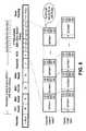
- FIG. 3is a block diagram of one embodiment of a packet format of a PHY mode segmentation.
- FIG. 4is a block diagram of an example of a packet of a PHY mode segmentation.
- High Rate PHY (HRP) packetconsists of several regions: EEP, UEP MSB-only Retry, and UEP.
- EEP regioninclude Audio, Video, and Control sub-packets.
- UEP MSB-only Retry and UEPinclude video sub-packets.
- Each sub-packetcan have a different Modulation Coding Scheme (MCS).
- MCSModulation Coding Scheme
- each sub-packetis coded at a separately specified MCS.
- the sub-packet MCScan be ordered from most robust to least robust.
- Adjacent sub-packets using the same MCScan be kept together in PHY. PHY only tails of and pads out sub-packets of different rate/coding. Full efficiency of the three segments EEPIUEP-MSB/UEP are maintained. Other combinations can be accommodated. The lengths are only specified in a single place in the header.
- FIG. 5is a block diagram of more detailed view of FIG. 3 , showing one embodiment of PHY segmentation with separate sub-packet length/MCS pairs in a PHY header followed by sub-packet type and ack group information in a separate PHY header.
- FIG. 6is a block diagram of one embodiment of data regions of a composite packet format. Each sub-packet is followed by a pair of CRCs. In another embodiment, each sub-packet is followed by a single CRC. In one embodiment, sub-packets with protected content have the Initialization Vector preceding the sub-packet data. In another embodiment, a single IV value per packet in is placed in the packet header. In this embodiment, each sub-packet's IV could be derived from the packet IV. One embodiment derives the sub-packet IV as fixed additions to the packet IV.
- msb and lsb IVsare used to prevent errors in the lsbs or msbs from affecting the other set of bits.
- the IVshould cover same region as CRC.
- the two streamsare then encrypted separately.
- LR and HR PHYsDue to the nature of beamformed and omni-directional transmissions, such as those in 60 GHz and specified in WirelessHD, devices will transmit and/or receive using both Low Rate (LR) and High Rate (HR) physical layers (PHYs).
- the data rates using the LR and HR PHYscan differ by over a factor of 1000. Because of this, the LR and HR PHYs carry packets of different size, ranging from less than 100 bytes on LR, to several hundred kilobytes on HR. In order to efficiently send MAC packets, it is necessary to aggregate MAC packets so that they are not too short for HR PHY transmission or too long for LR PHY transmission.
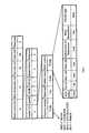
- FIG. 7is a block diagram of one embodiment of a MAC header format capable of the unified aggregation and fragmentation using the following specification.
- the packet or sub-packet's payloadcan contain one or multiple sub-payloads:
- the sub-payload field at the start of the sub-payloadallows a unitied approach to handle fragments of a MSDU or an aggregate of MSDUs (MAC service data unit) in the packet.
- the Length fieldindicates the length of the MSDU.
- the sequence number fieldis incremented for each MSDU.
- the keyis the fragment fields which indicate whether it is a fragment or a complete MSDU.
- the HRP, LRP Short-Omni and LRP Beam-forming packetsmay be shortened for efficiency reasons. Because of this, it would be harder to recover timing and detect start of packets in a Channel Time Block (CTB) in case of packet header losses.
- CTBChannel Time Block
- IPPis used to determine the start of packets within a multi-packet CTB. This establishes well-known synchronization points in time for the receiver to look for a packet header.
- nis an integer greater than or equal to 0 such that the end of the last packet is within the CTB.
- Time Division Multiple Access (TDMA) systemssuch as those that can be used in the present invention, often schedule data and control packets such as beacons at static or semi-static intervals to allow greater robustness.
- Beaconscan consist of Informational Elements (IE) which carry the information.
- IEInformational Elements
- the beaconssometimes need to carry additional IEs that would extend past their normal length.
- the conventional approachis to increase the length of the beacon always. However, this decreases overall efficiency.
- the packet scheduled to immediately follow itis not transmitted, instead allowing the beacon to extend into the suppressed packet's time slot.
- the packet scheduled to immediately follow the beaconis the Random Access Time Block (RATB).
- RTBRandom Access Time Block
- Data deliveryhas an interlocked relationship with the MAC schedule, A/V composite packet format and beam search operation.
- the receiver in the networkhas to have knowledge of when the transmitter is sending data packets versus beam search packets. In case of lost transmission over the wireless link, the receiver should be able to recover and synchronize at the next packet boundary. So with the definition of Inter Packet Period (IPP) within a Channel Time Block (CTB), the receiver knows the points of intercept for packet reception. Additionally when the receivers acknowledges the transmitter of packet reception the ACK packet are defined to be received at a specific time enabling the transmitter to detect when ACK packets are lost.
- IPPInter Packet Period
- CTBChannel Time Block
- Beam Search and Beam Track packetsthey follow the rule of a Single IPP (Beam Track) or Multiple IPP (Beam Search) boundaries.
- Long omni preamble and short omni preambleare effectively used to achieve both timing recovery and synchronization in the WiHD Network.
- Long omni LRP preambleallows blind timing recovery (i.e. for beacons).
- Short omni LRP preambleonly allows limited timing adjustment (for efficiency).
- the usage of these preambleshas been optimized so as to provide accurate timing recovery as well reduced overhead due to preamble length.
- Long Omni LRPDU formatis used for beacons and unscheduled packets while Short Omni LRPDU format is used for contention period, scheduled packets.
- two versions of the omni LRPDUare defined: the long omni LRPDU which uses the long omni LRP preamble, ⁇ 56.5 ⁇ s duration, and the short omni LRPDU which uses the short omni LRP preamble, ⁇ 43.1 ⁇ s duration.
- the long omni LRPDUis used for beacons and unscheduled LRP packets while the short omni LRPDU is used for packets sent during a contention period or any other scheduled LRP packet.
- the present inventionalso relates to an apparatus for performing the operations herein.
- This apparatusmay be specially constructed for the required purposes, or it may comprise a general purpose computer selectively activated or reconfigured by a computer program stored in the computer.
- a computer programmay be stored in a computer readable storage medium, such as, but is not limited to, any type of disk including floppy disks, optical disks, CD-ROMs, and magnetic-optical disks, read-only memories (ROMs), random access memories (RAMs), EPROMs, EEPROMs, magnetic or optical cards, or any type of media suitable for storing electronic instructions, and each coupled to a computer system bus.
- a machine-readable mediumincludes any mechanism for storing or transmitting information in a form readable by a machine (e.g., a computer).
- a machine-readable mediumincludes read only memory (“ROM”); random access memory (“RAM”); magnetic disk storage media; optical storage media; flash memory devices; electrical, optical, acoustical or other form of propagated signals (e.g., carrier waves, infrared signals, digital signals, etc.); etc.
Landscapes
- Engineering & Computer Science (AREA)
- Computer Networks & Wireless Communication (AREA)
- Signal Processing (AREA)
- Multimedia (AREA)
- Mobile Radio Communication Systems (AREA)
- Data Exchanges In Wide-Area Networks (AREA)
- Communication Control (AREA)
Abstract
Description
| Octets: variable | Variable | . . . | Variable | ||
| Sub-payload 1 | . . . | Subpayload N | |||
| Bits: 20 | 10 | 1 | 1 | Variable |
| Length | Sequence number | Last fragment | First fragment | MSDU |
| Fragment type | Last fragment field | First fragment field | ||
| 0 | 1 | |||
| 1 | 0 | |||
| 0 | 0 | |||
| 1 | 1 | |||
Inter-Packet Period (IPP)
IPP=Packet Duration+ACK duration+2*SIFS Duration.
CTBtime+n*IPP
Claims (23)
Priority Applications (6)
| Application Number | Priority Date | Filing Date | Title |
|---|---|---|---|
| US11/981,935US9065682B2 (en) | 2006-11-01 | 2007-10-31 | Wireless HD MAC frame format |
| EP07861650AEP2078396B1 (en) | 2006-11-01 | 2007-11-01 | Wireless hd mac frame format |
| AT07861650TATE503324T1 (en) | 2006-11-01 | 2007-11-01 | WIRELESS HD MAC FRAME FORMAT |
| DE602007013439TDE602007013439D1 (en) | 2006-11-01 | 2007-11-01 | WIRELESS HD MAC FRAME FORMAT |
| PCT/US2007/023125WO2008057406A2 (en) | 2006-11-01 | 2007-11-01 | Wireless hd mac frame format |
| TW096141236ATWI441484B (en) | 2006-11-01 | 2007-11-01 | Apparatus and method for generating wireless hd mac frame format |
Applications Claiming Priority (8)
| Application Number | Priority Date | Filing Date | Title |
|---|---|---|---|
| US85610406P | 2006-11-01 | 2006-11-01 | |
| US87375906P | 2006-12-08 | 2006-12-08 | |
| US90138807P | 2007-02-14 | 2007-02-14 | |
| US90138407P | 2007-02-14 | 2007-02-14 | |
| US92033807P | 2007-03-26 | 2007-03-26 | |
| US92035707P | 2007-03-26 | 2007-03-26 | |
| US92026607P | 2007-03-26 | 2007-03-26 | |
| US11/981,935US9065682B2 (en) | 2006-11-01 | 2007-10-31 | Wireless HD MAC frame format |
Publications (2)
| Publication Number | Publication Date |
|---|---|
| US20080192726A1 US20080192726A1 (en) | 2008-08-14 |
| US9065682B2true US9065682B2 (en) | 2015-06-23 |
Family
ID=39365062
Family Applications (1)
| Application Number | Title | Priority Date | Filing Date |
|---|---|---|---|
| US11/981,935Active2032-07-18US9065682B2 (en) | 2006-11-01 | 2007-10-31 | Wireless HD MAC frame format |
Country Status (6)
| Country | Link |
|---|---|
| US (1) | US9065682B2 (en) |
| EP (1) | EP2078396B1 (en) |
| AT (1) | ATE503324T1 (en) |
| DE (1) | DE602007013439D1 (en) |
| TW (1) | TWI441484B (en) |
| WO (1) | WO2008057406A2 (en) |
Cited By (2)
| Publication number | Priority date | Publication date | Assignee | Title |
|---|---|---|---|---|
| US9825730B1 (en)* | 2016-09-26 | 2017-11-21 | Dell Products, Lp | System and method for optimizing link performance with lanes operating at different speeds |
| US20230047803A1 (en)* | 2020-02-18 | 2023-02-16 | Sharp Kabushiki Kaisha | Station apparatus and communication method |
Families Citing this family (49)
| Publication number | Priority date | Publication date | Assignee | Title |
|---|---|---|---|---|
| US7782836B2 (en)* | 2006-03-24 | 2010-08-24 | Samsung Electronics Co., Ltd. | Method and system for transmission of different types of information in wireless communication |
| US8259647B2 (en)* | 2006-06-12 | 2012-09-04 | Samsung Electronics Co., Ltd. | System and method for wireless communication of uncompressed video having a link control and bandwidth reservation scheme for control/management message exchanges and asynchronous traffic |
| KR100917889B1 (en)* | 2006-11-01 | 2009-09-16 | 삼성전자주식회사 | Apparatus and method for wireless communication |
| US8306060B2 (en) | 2006-11-07 | 2012-11-06 | Samsung Electronics Co., Ltd. | System and method for wireless communication of uncompressed video having a composite frame format |
| US8169995B2 (en)* | 2006-12-04 | 2012-05-01 | Samsung Electronics Co., Ltd. | System and method for wireless communication of uncompressed video having delay-insensitive data transfer |
| US20080159356A1 (en)* | 2006-12-28 | 2008-07-03 | Samsung Electronics Co., Ltd. | Method and a system for low-rate channel communication in wireless communication systems |
| KR20080062886A (en)* | 2006-12-29 | 2008-07-03 | 삼성전자주식회사 | Method and apparatus for transmitting reverse control channel response channel for forward sharing control channel in orthogonal frequency multiple access mobile communication system |
| JP5474823B2 (en)* | 2007-12-28 | 2014-04-16 | コーニンクレッカ フィリップス エヌ ヴェ | System and method for multi-resolution packet communication for ultra-low power wireless networks |
| US8509439B2 (en)* | 2007-12-31 | 2013-08-13 | Intel Corporation | Assigning nonces for security keys |
| US8638653B2 (en)* | 2008-03-27 | 2014-01-28 | Intel Corporation | Adaptive transmissions for optimized application delivery in wireless networks |
| US8000655B2 (en) | 2008-12-19 | 2011-08-16 | Telefonaktiebolaget L M Ericsson (Publ) | Uplink multi-cell signal processing for interference suppression |
| US9960820B2 (en) | 2008-12-23 | 2018-05-01 | Keyssa, Inc. | Contactless data transfer systems and methods |
| US9474099B2 (en) | 2008-12-23 | 2016-10-18 | Keyssa, Inc. | Smart connectors and associated communications links |
| US8794980B2 (en) | 2011-12-14 | 2014-08-05 | Keyssa, Inc. | Connectors providing HAPTIC feedback |
| US9954579B2 (en) | 2008-12-23 | 2018-04-24 | Keyssa, Inc. | Smart connectors and associated communications links |
| US9219956B2 (en) | 2008-12-23 | 2015-12-22 | Keyssa, Inc. | Contactless audio adapter, and methods |
| US9191263B2 (en) | 2008-12-23 | 2015-11-17 | Keyssa, Inc. | Contactless replacement for cabled standards-based interfaces |
| US8554136B2 (en) | 2008-12-23 | 2013-10-08 | Waveconnex, Inc. | Tightly-coupled near-field communication-link connector-replacement chips |
| KR101615082B1 (en) | 2011-03-24 | 2016-04-29 | 키사, 아이엔씨. | Integrated circuit with electromagnetic communication |
| US8714459B2 (en) | 2011-05-12 | 2014-05-06 | Waveconnex, Inc. | Scalable high-bandwidth connectivity |
| US9614590B2 (en) | 2011-05-12 | 2017-04-04 | Keyssa, Inc. | Scalable high-bandwidth connectivity |
| US8811526B2 (en) | 2011-05-31 | 2014-08-19 | Keyssa, Inc. | Delta modulated low power EHF communication link |
| TWI569031B (en) | 2011-06-15 | 2017-02-01 | 奇沙公司 | Near-end sensing and distance measurement using EHF signals |
| KR101879907B1 (en) | 2011-09-15 | 2018-08-16 | 키사, 아이엔씨. | Wireless communication with dielectric medium |
| EP2769477A1 (en) | 2011-10-20 | 2014-08-27 | Keyssa, Inc. | Low-profile wireless connectors |
| TWI562555B (en) | 2011-10-21 | 2016-12-11 | Keyssa Inc | Contactless signal splicing |
| US9344201B2 (en) | 2012-01-30 | 2016-05-17 | Keyssa, Inc. | Shielded EHF connector assemblies |
| US9559790B2 (en) | 2012-01-30 | 2017-01-31 | Keyssa, Inc. | Link emission control |
| CN107276641B (en) | 2012-03-02 | 2021-07-02 | 凯萨股份有限公司 | Duplex communication system and method |
| CN104303436B (en) | 2012-03-06 | 2017-04-05 | 凯萨股份有限公司 | System for constraining operating parameters of an EHF communication chip |
| EP2832192B1 (en) | 2012-03-28 | 2017-09-27 | Keyssa, Inc. | Redirection of electromagnetic signals using substrate structures |
| CN104321930A (en) | 2012-04-17 | 2015-01-28 | 凯萨股份有限公司 | Dielectric lens structures for interchip communication |
| JP5482823B2 (en)* | 2012-05-11 | 2014-05-07 | オンキヨー株式会社 | Transmitter |
| EP2883271B1 (en) | 2012-08-10 | 2020-07-22 | Keyssa, Inc. | Dielectric coupling systems for ehf communications |
| US9374154B2 (en) | 2012-09-14 | 2016-06-21 | Keyssa, Inc. | Wireless connections with virtual hysteresis |
| GB2506349B (en)* | 2012-09-21 | 2015-12-16 | Canon Kk | Method and device for transmitting uncompressed video streams |
| WO2014100058A1 (en) | 2012-12-17 | 2014-06-26 | Waveconnex, Inc. | Modular electronics |
| KR20150132459A (en) | 2013-03-15 | 2015-11-25 | 키사, 아이엔씨. | Ehf secure communication device |
| TWI551093B (en) | 2013-03-15 | 2016-09-21 | 奇沙公司 | Extremely high frequency communication chip |
| US20140313951A1 (en)* | 2013-04-17 | 2014-10-23 | Qualcomm Incorporated | Physical-layer control channel structure |
| US9407731B2 (en) | 2013-05-16 | 2016-08-02 | Keyssa, Inc. | Extremely high frequency converter |
| US9985996B2 (en)* | 2013-09-09 | 2018-05-29 | Avago Technologies General Ip (Singapore) Pte. Ltd. | Decoupling audio-video (AV) traffic processing from non-AV traffic processing |
| CN114827299B (en) | 2014-11-11 | 2024-06-28 | 三星电子株式会社 | Transmitting device, receiving device and control method thereof |
| WO2016136491A1 (en)* | 2015-02-23 | 2016-09-01 | 京セラ株式会社 | Transmission device and reception device |
| GB2536299C (en)* | 2015-03-13 | 2017-07-05 | Gurulogic Microsystems Oy | Method of communicating data packets within data communication systems |
| US9602648B2 (en) | 2015-04-30 | 2017-03-21 | Keyssa Systems, Inc. | Adapter devices for enhancing the functionality of other devices |
| US10049801B2 (en) | 2015-10-16 | 2018-08-14 | Keyssa Licensing, Inc. | Communication module alignment |
| CN115865590A (en)* | 2021-09-23 | 2023-03-28 | 中兴通讯股份有限公司 | Signal modulation method, device and storage medium |
| US20240014924A1 (en)* | 2022-07-05 | 2024-01-11 | Qualcomm Incorporated | Dynamic reporting of multi-level coding configurations |
Citations (20)
| Publication number | Priority date | Publication date | Assignee | Title |
|---|---|---|---|---|
| US20010037388A1 (en)* | 2000-03-31 | 2001-11-01 | International Business Machines Corporation | Method and apparatus for communicating with network from comunication terminal |
| US6570890B1 (en) | 1998-06-10 | 2003-05-27 | Merlot Communications | Method for the transmission and control of audio, video, and computer data over a single network fabric using ethernet packets |
| US20030185241A1 (en)* | 2002-04-01 | 2003-10-02 | Texas Instruments Incorporated | Wireless network scheduling data frames including physical layer configuration |
| US20030185169A1 (en)* | 2002-03-27 | 2003-10-02 | Higgins James A. | Wireless internet access system |
| US20040170121A1 (en) | 2003-02-28 | 2004-09-02 | Samsung Electronics Co., Ltd. | Apparatus and method for transmitting header information in an ultra wide band communication system |
| US20050135310A1 (en)* | 2003-12-19 | 2005-06-23 | International Business Machines Corporation | Autonomic client reassociation in a wireless local area network |
| US20050177639A1 (en)* | 2004-02-06 | 2005-08-11 | Jukka Reunamaki | Device discovery and connection establishment for ad hoc networks |
| US6934752B1 (en) | 2000-03-23 | 2005-08-23 | Sharewave, Inc. | Quality of service extensions for multimedia applications in wireless computer networks |
| US20050213554A1 (en)* | 2004-03-29 | 2005-09-29 | Boris Ginzburg | Method, apparatus and system of packet transmission |
| US20050265298A1 (en)* | 2004-05-28 | 2005-12-01 | Tomoko Adachi | Wireless communication system and wireless terminal |
| US20060116147A1 (en)* | 2004-09-30 | 2006-06-01 | Sanyo Electric Co., Ltd. | Communication apparatus, communication program, and communication method |
| US20060126492A1 (en)* | 2004-12-10 | 2006-06-15 | Electronics And Telecommunications Research Institute | Method and apparatus for transmitting data based on OFDM |
| US20060215774A1 (en)* | 2005-03-28 | 2006-09-28 | Gadi Shor | Method and device for OFDM channel estimation |
| US20060251115A1 (en)* | 2004-12-03 | 2006-11-09 | Haque Samudra E | Broadband multi-service, switching, transmission and distribution architecture for low-cost telecommunications networks |
| US20070014273A1 (en)* | 2005-07-13 | 2007-01-18 | Yefim Kuperschmidt | Method, device and computer readable medium for dynamically updating transmission charactaristics |
| US20070015544A1 (en)* | 2005-07-17 | 2007-01-18 | David Garrett | Multi-sector base station and shared processing information |
| US20070160003A1 (en)* | 2006-01-09 | 2007-07-12 | Cisco Technology, Inc. | Hybrid QoS access method for power save stations |
| US20070270115A1 (en)* | 2006-05-16 | 2007-11-22 | Research In Motion Limited | Mobile wireless communications device having low-if receiver circuitry that adapts to radio environment |
| US20080049707A1 (en)* | 2006-07-12 | 2008-02-28 | Samsung Electronics Co., Ltd. | Transmission packet for wireless transmission in a high frequency band, and method and apparatus for transmission/receiving using the same |
| US7701975B1 (en)* | 2003-11-19 | 2010-04-20 | Marvell International Ltd. | Technique for reducing physical layer (PHY) overhead in wireless LAN systems |
- 2007
- 2007-10-31USUS11/981,935patent/US9065682B2/enactiveActive
- 2007-11-01TWTW096141236Apatent/TWI441484B/ennot_activeIP Right Cessation
- 2007-11-01EPEP07861650Apatent/EP2078396B1/ennot_activeNot-in-force
- 2007-11-01DEDE602007013439Tpatent/DE602007013439D1/enactiveActive
- 2007-11-01ATAT07861650Tpatent/ATE503324T1/ennot_activeIP Right Cessation
- 2007-11-01WOPCT/US2007/023125patent/WO2008057406A2/enactiveApplication Filing
Patent Citations (20)
| Publication number | Priority date | Publication date | Assignee | Title |
|---|---|---|---|---|
| US6570890B1 (en) | 1998-06-10 | 2003-05-27 | Merlot Communications | Method for the transmission and control of audio, video, and computer data over a single network fabric using ethernet packets |
| US6934752B1 (en) | 2000-03-23 | 2005-08-23 | Sharewave, Inc. | Quality of service extensions for multimedia applications in wireless computer networks |
| US20010037388A1 (en)* | 2000-03-31 | 2001-11-01 | International Business Machines Corporation | Method and apparatus for communicating with network from comunication terminal |
| US20030185169A1 (en)* | 2002-03-27 | 2003-10-02 | Higgins James A. | Wireless internet access system |
| US20030185241A1 (en)* | 2002-04-01 | 2003-10-02 | Texas Instruments Incorporated | Wireless network scheduling data frames including physical layer configuration |
| US20040170121A1 (en) | 2003-02-28 | 2004-09-02 | Samsung Electronics Co., Ltd. | Apparatus and method for transmitting header information in an ultra wide band communication system |
| US7701975B1 (en)* | 2003-11-19 | 2010-04-20 | Marvell International Ltd. | Technique for reducing physical layer (PHY) overhead in wireless LAN systems |
| US20050135310A1 (en)* | 2003-12-19 | 2005-06-23 | International Business Machines Corporation | Autonomic client reassociation in a wireless local area network |
| US20050177639A1 (en)* | 2004-02-06 | 2005-08-11 | Jukka Reunamaki | Device discovery and connection establishment for ad hoc networks |
| US20050213554A1 (en)* | 2004-03-29 | 2005-09-29 | Boris Ginzburg | Method, apparatus and system of packet transmission |
| US20050265298A1 (en)* | 2004-05-28 | 2005-12-01 | Tomoko Adachi | Wireless communication system and wireless terminal |
| US20060116147A1 (en)* | 2004-09-30 | 2006-06-01 | Sanyo Electric Co., Ltd. | Communication apparatus, communication program, and communication method |
| US20060251115A1 (en)* | 2004-12-03 | 2006-11-09 | Haque Samudra E | Broadband multi-service, switching, transmission and distribution architecture for low-cost telecommunications networks |
| US20060126492A1 (en)* | 2004-12-10 | 2006-06-15 | Electronics And Telecommunications Research Institute | Method and apparatus for transmitting data based on OFDM |
| US20060215774A1 (en)* | 2005-03-28 | 2006-09-28 | Gadi Shor | Method and device for OFDM channel estimation |
| US20070014273A1 (en)* | 2005-07-13 | 2007-01-18 | Yefim Kuperschmidt | Method, device and computer readable medium for dynamically updating transmission charactaristics |
| US20070015544A1 (en)* | 2005-07-17 | 2007-01-18 | David Garrett | Multi-sector base station and shared processing information |
| US20070160003A1 (en)* | 2006-01-09 | 2007-07-12 | Cisco Technology, Inc. | Hybrid QoS access method for power save stations |
| US20070270115A1 (en)* | 2006-05-16 | 2007-11-22 | Research In Motion Limited | Mobile wireless communications device having low-if receiver circuitry that adapts to radio environment |
| US20080049707A1 (en)* | 2006-07-12 | 2008-02-28 | Samsung Electronics Co., Ltd. | Transmission packet for wireless transmission in a high frequency band, and method and apparatus for transmission/receiving using the same |
Non-Patent Citations (2)
| Title |
|---|
| PCT International Search Report dated Sep. 16, 2008, for PCT Patent Application No. PCT/US07/023125 filed Nov. 1, 2007, 5 Pages. |
| Written Opinion of the International Searching Authority dated Sep. 16, 2008, for PCT Patent Application No. PCT/US07/023125, filed Nov. 1, 2007, 7 Pages. |
Cited By (2)
| Publication number | Priority date | Publication date | Assignee | Title |
|---|---|---|---|---|
| US9825730B1 (en)* | 2016-09-26 | 2017-11-21 | Dell Products, Lp | System and method for optimizing link performance with lanes operating at different speeds |
| US20230047803A1 (en)* | 2020-02-18 | 2023-02-16 | Sharp Kabushiki Kaisha | Station apparatus and communication method |
Also Published As
| Publication number | Publication date |
|---|---|
| EP2078396A2 (en) | 2009-07-15 |
| EP2078396B1 (en) | 2011-03-23 |
| WO2008057406A2 (en) | 2008-05-15 |
| ATE503324T1 (en) | 2011-04-15 |
| US20080192726A1 (en) | 2008-08-14 |
| DE602007013439D1 (en) | 2011-05-05 |
| WO2008057406A3 (en) | 2008-10-23 |
| TW200838230A (en) | 2008-09-16 |
| TWI441484B (en) | 2014-06-11 |
Similar Documents
| Publication | Publication Date | Title |
|---|---|---|
| US9065682B2 (en) | Wireless HD MAC frame format | |
| US8279784B2 (en) | Wireless HD AV packet format | |
| US8306060B2 (en) | System and method for wireless communication of uncompressed video having a composite frame format | |
| US8014416B2 (en) | HD physical layer of a wireless communication device | |
| US8031691B2 (en) | System and method for wireless communication of uncompressed video having acknowledgment (ACK) frames | |
| US8102853B2 (en) | System and method for wireless communication of uncompressed video having fixed size MAC header with an extension | |
| US8630312B2 (en) | System and method for wireless communication of uncompressed video having connection control protocol | |
| US8230288B2 (en) | Data transmission apparatus and method for applying an appropriate coding rate | |
| US7765599B2 (en) | Multimedia transmitter, multimedia receiver, multimedia transmission system, and method for securely transmitting multimedia content over a wireless link | |
| US9609382B2 (en) | Apparatus and method for wireless communications | |
| US20080130561A1 (en) | System and method for wireless communication | |
| KR20080054384A (en) | Wireless communication device using adaptive beamforming | |
| US8205126B2 (en) | System and method for wireless communication of uncompressed video using selective retransmission | |
| JP2008527917A (en) | Method and system using multiple 60 GHz system antennas | |
| US20090077611A1 (en) | System and method for wireless communication of uncompressed video having reed-solomon code error concealment | |
| KR101205499B1 (en) | System and method for wireless communication of uncompressed video having acknowledgementack frames |
Legal Events
| Date | Code | Title | Description |
|---|---|---|---|
| AS | Assignment | Owner name:SIBEAM, INC., CALIFORNIA Free format text:ASSIGNMENT OF ASSIGNORS INTEREST;ASSIGNORS:MAHESH, KUMAR;KRISHNASWAMI, KARTHIK;WANG, KAREN;AND OTHERS;REEL/FRAME:020855/0844;SIGNING DATES FROM 20080227 TO 20080303 Owner name:SIBEAM, INC., CALIFORNIA Free format text:ASSIGNMENT OF ASSIGNORS INTEREST;ASSIGNORS:MAHESH, KUMAR;KRISHNASWAMI, KARTHIK;WANG, KAREN;AND OTHERS;SIGNING DATES FROM 20080227 TO 20080303;REEL/FRAME:020855/0844 | |
| AS | Assignment | Owner name:JEFFERIES FINANCE LLC, NEW YORK Free format text:SECURITY INTEREST;ASSIGNORS:LATTICE SEMICONDUCTOR CORPORATION;SIBEAM, INC.;SILICON IMAGE, INC.;AND OTHERS;REEL/FRAME:035226/0289 Effective date:20150310 | |
| STCF | Information on status: patent grant | Free format text:PATENTED CASE | |
| AS | Assignment | Owner name:SIBEAM, INC., CALIFORNIA Free format text:ASSIGNMENT OF ASSIGNORS INTEREST;ASSIGNOR:MAHESH, KUMAR;REEL/FRAME:040990/0460 Effective date:20060314 Owner name:SIBEAM, INC., CALIFORNIA Free format text:CORRECTIVE ASSIGNMENT TO CORRECT THE ASSIGNEE INSIDE THE ASSIGNMENT DOCUMENT PREVIOUSLY RECORDED AT REEL: 020855 FRAME: 0844. ASSIGNOR(S) HEREBY CONFIRMS THE ASSIGNMENT;ASSIGNORS:KRISHNASWAMI, KARTHIK;WANG, KAREN;GILBERT, JEFFREY M.;AND OTHERS;SIGNING DATES FROM 20080227 TO 20080303;REEL/FRAME:041384/0066 | |
| AS | Assignment | Owner name:SIBEAM, INC., OREGON Free format text:RELEASE BY SECURED PARTY;ASSIGNOR:JEFFERIES FINANCE LLC;REEL/FRAME:041905/0860 Effective date:20170307 Owner name:QUALCOMM INCORPORATED, CALIFORNIA Free format text:ASSIGNMENT OF ASSIGNORS INTEREST;ASSIGNORS:LATTICE SEMICONDUCTOR CORPORATION;SIBEAM, INC.;REEL/FRAME:041905/0814 Effective date:20170302 Owner name:DVDO, INC., OREGON Free format text:RELEASE BY SECURED PARTY;ASSIGNOR:JEFFERIES FINANCE LLC;REEL/FRAME:041905/0860 Effective date:20170307 Owner name:SILICON IMAGE, INC., OREGON Free format text:RELEASE BY SECURED PARTY;ASSIGNOR:JEFFERIES FINANCE LLC;REEL/FRAME:041905/0860 Effective date:20170307 Owner name:LATTICE SEMICONDUCTOR CORPORATION, OREGON Free format text:RELEASE BY SECURED PARTY;ASSIGNOR:JEFFERIES FINANCE LLC;REEL/FRAME:041905/0860 Effective date:20170307 | |
| MAFP | Maintenance fee payment | Free format text:PAYMENT OF MAINTENANCE FEE, 4TH YEAR, LARGE ENTITY (ORIGINAL EVENT CODE: M1551); ENTITY STATUS OF PATENT OWNER: LARGE ENTITY Year of fee payment:4 | |
| AS | Assignment | Owner name:SIBEAM, INC., OREGON Free format text:RELEASE BY SECURED PARTY;ASSIGNOR:JEFFERIES FINANCE LLC;REEL/FRAME:049827/0326 Effective date:20190517 Owner name:SILICON IMAGE, INC., OREGON Free format text:RELEASE BY SECURED PARTY;ASSIGNOR:JEFFERIES FINANCE LLC;REEL/FRAME:049827/0326 Effective date:20190517 Owner name:LATTICE SEMICONDUCTOR CORPORATION, OREGON Free format text:RELEASE BY SECURED PARTY;ASSIGNOR:JEFFERIES FINANCE LLC;REEL/FRAME:049827/0326 Effective date:20190517 Owner name:DVDO, INC., OREGON Free format text:RELEASE BY SECURED PARTY;ASSIGNOR:JEFFERIES FINANCE LLC;REEL/FRAME:049827/0326 Effective date:20190517 | |
| MAFP | Maintenance fee payment | Free format text:PAYMENT OF MAINTENANCE FEE, 8TH YEAR, LARGE ENTITY (ORIGINAL EVENT CODE: M1552); ENTITY STATUS OF PATENT OWNER: LARGE ENTITY Year of fee payment:8 |