US9065293B2 - Battery heating circuits and methods using transformers - Google Patents
Battery heating circuits and methods using transformersDownload PDFInfo
- Publication number
- US9065293B2 US9065293B2US13/544,881US201213544881AUS9065293B2US 9065293 B2US9065293 B2US 9065293B2US 201213544881 AUS201213544881 AUS 201213544881AUS 9065293 B2US9065293 B2US 9065293B2
- Authority
- US
- United States
- Prior art keywords
- battery
- circuit
- component
- winding
- switch unit
- Prior art date
- Legal status (The legal status is an assumption and is not a legal conclusion. Google has not performed a legal analysis and makes no representation as to the accuracy of the status listed.)
- Active, expires
Links
Images


Classifications
- H02J7/047—
- H—ELECTRICITY
- H01—ELECTRIC ELEMENTS
- H01M—PROCESSES OR MEANS, e.g. BATTERIES, FOR THE DIRECT CONVERSION OF CHEMICAL ENERGY INTO ELECTRICAL ENERGY
- H01M10/00—Secondary cells; Manufacture thereof
- H01M10/60—Heating or cooling; Temperature control
- H01M10/63—Control systems
- H01M10/637—Control systems characterised by the use of reversible temperature-sensitive devices, e.g. NTC, PTC or bimetal devices; characterised by control of the internal current flowing through the cells, e.g. by switching
- H01M10/5006—
- H01M10/5026—
- H01M10/5083—
- H—ELECTRICITY
- H01—ELECTRIC ELEMENTS
- H01M—PROCESSES OR MEANS, e.g. BATTERIES, FOR THE DIRECT CONVERSION OF CHEMICAL ENERGY INTO ELECTRICAL ENERGY
- H01M10/00—Secondary cells; Manufacture thereof
- H01M10/60—Heating or cooling; Temperature control
- H01M10/61—Types of temperature control
- H01M10/615—Heating or keeping warm
- H—ELECTRICITY
- H01—ELECTRIC ELEMENTS
- H01M—PROCESSES OR MEANS, e.g. BATTERIES, FOR THE DIRECT CONVERSION OF CHEMICAL ENERGY INTO ELECTRICAL ENERGY
- H01M10/00—Secondary cells; Manufacture thereof
- H01M10/60—Heating or cooling; Temperature control
- H01M10/65—Means for temperature control structurally associated with the cells
- H01M10/657—Means for temperature control structurally associated with the cells by electric or electromagnetic means
- H01M10/6571—Resistive heaters
- H—ELECTRICITY
- H02—GENERATION; CONVERSION OR DISTRIBUTION OF ELECTRIC POWER
- H02J—CIRCUIT ARRANGEMENTS OR SYSTEMS FOR SUPPLYING OR DISTRIBUTING ELECTRIC POWER; SYSTEMS FOR STORING ELECTRIC ENERGY
- H02J7/00—Circuit arrangements for charging or depolarising batteries or for supplying loads from batteries
- H02J7/007—Regulation of charging or discharging current or voltage
- H02J7/007188—Regulation of charging or discharging current or voltage the charge cycle being controlled or terminated in response to non-electric parameters
- H02J7/007192—Regulation of charging or discharging current or voltage the charge cycle being controlled or terminated in response to non-electric parameters in response to temperature
- H—ELECTRICITY
- H02—GENERATION; CONVERSION OR DISTRIBUTION OF ELECTRIC POWER
- H02J—CIRCUIT ARRANGEMENTS OR SYSTEMS FOR SUPPLYING OR DISTRIBUTING ELECTRIC POWER; SYSTEMS FOR STORING ELECTRIC ENERGY
- H02J7/00—Circuit arrangements for charging or depolarising batteries or for supplying loads from batteries
- H02J7/02—Circuit arrangements for charging or depolarising batteries or for supplying loads from batteries for charging batteries from AC mains by converters
- H02J7/04—Regulation of charging current or voltage
- Y—GENERAL TAGGING OF NEW TECHNOLOGICAL DEVELOPMENTS; GENERAL TAGGING OF CROSS-SECTIONAL TECHNOLOGIES SPANNING OVER SEVERAL SECTIONS OF THE IPC; TECHNICAL SUBJECTS COVERED BY FORMER USPC CROSS-REFERENCE ART COLLECTIONS [XRACs] AND DIGESTS
- Y02—TECHNOLOGIES OR APPLICATIONS FOR MITIGATION OR ADAPTATION AGAINST CLIMATE CHANGE
- Y02E—REDUCTION OF GREENHOUSE GAS [GHG] EMISSIONS, RELATED TO ENERGY GENERATION, TRANSMISSION OR DISTRIBUTION
- Y02E60/00—Enabling technologies; Technologies with a potential or indirect contribution to GHG emissions mitigation
- Y02E60/10—Energy storage using batteries
Definitions
- the present inventionpertains to electric and electronic field, in particular related to a battery heating circuit.
- the batterywhich serves as the power supply unit for electric-motor cars or electronic devices, need to be adaptive to these complex conditions.
- the service life and charge/discharge cycle performance of the batteryneed to be taken into consideration; especially, when electric-motor cars or electronic devices are used in low temperature environments, the battery needs to have outstanding low-temperature charge/discharge performance and higher input/output power performance.
- some embodiments of the present inventionprovide a battery heating circuit.
- the objective of certain embodiments of the present inventionis to provide a battery heating circuit, in order to solve the problem of decreased capacity of the battery caused by increased resistance and polarization of the battery under low temperature conditions.
- the battery heating circuitcomprises a switch unit, a switching control module, a one-way semiconductor component, a damping component and a transformer, wherein the switching control module is electrically connected with the switch unit; the battery, the damping component, the first winding of the transformer, and the switch unit are connected in series with each other to constitute a battery discharging circuit; the battery, the damping component, the second winding of the transformer, and the one-way semiconductor component are connected in series with each other to constitute a battery charging circuit.
- the switch unitwhen the battery is to be heated up, can be controlled by the switching control module to switch on, and then can be controlled to switch off when the current in the battery discharging circuit reaches a preset value; after that, the transformer transfers the stored energy back to the battery.
- the damping componentgenerates heat as the current flows through it, and thereby heats up the battery.
- the transformertakes a current limiting role; in addition, the preset value can be set according to the properties of the battery; therefore, the magnitude of current in the battery charging/discharging circuit is controllable, and damages to the battery caused by over-current can be avoided.
- the switch unitsince the magnitude of current is controllable, the switch unit is protected against being burned due to generation of vast heat according to another embodiment.
- the transformer in certain embodiments of the present inventionserves as an energy storage component, and has current limiting function.
- the transformercan transfer the energy stored in it back to the battery through the battery charging circuit, and thereby can reduce the energy loss in the heating process.
- FIG. 1is a circuit diagram of the heating circuit according to one embodiment of the present invention.
- FIG. 2is a timing diagram of waveforms of the heating circuit according to one embodiment of the present invention.
- FIG. 3is a circuit diagram of the heating circuit according to another embodiment of the present invention.
- FIG. 4is a circuit diagram of the heating circuit according to yet another embodiment of the present invention.
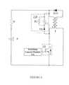
- FIG. 5is a circuit diagram of the heating circuit according to yet another embodiment of the present invention.
- FIG. 6is a circuit diagram of the switch unit as part of the heating circuit according to certain embodiments of the present invention.
- FIG. 7is a circuit diagram of the switch unit as part of the heating circuit according to some embodiments of the present invention.
- switching control modulemay refer to any controller that can output control commands (e.g., pulse waveforms) under preset conditions or at preset times and thereby control the switch unit connected to it to switch on or switch off accordingly, according to some embodiments.
- the switching control modulecan be a PLC.
- switchmay refer to a switch that enables ON/OFF control by using electrical signals or enables ON/OFF control on the basis of the characteristics of the component according to certain embodiments.
- the switchcan be either a one-way switch (e.g., a switch composed of a two-way switch and a diode connected in series, which can be conductive in one direction) or a two-way switch (e.g., a Metal Oxide Semiconductor Field Effect Transistor (MOSFET) or an IGBT with an anti-parallel freewheeling diode).
- a two-way switche.g., a Metal Oxide Semiconductor Field Effect Transistor (MOSFET) or an IGBT with an anti-parallel freewheeling diode.
- MOSFETMetal Oxide Semiconductor Field Effect Transistor
- IGBTanti-parallel freewheeling diode
- the two-way switchcan be a MOSFET or an IGBT with an anti-parallel freewheeling diode.
- the term “one-way semiconductor component”may refer to a semiconductor component that can be conductive in one direction, such as a diode, according to certain embodiments.
- the term “charge storage component”may refer to any device that can enable charge storage, such as a capacitor, according to some embodiments.
- the term “current storage component”may refer to any device that can store current, such as an inductor, according to certain embodiments.
- the term “forward direction”may refer to the direction in which the energy flows from the battery to the energy storage circuit
- the term “reverse direction”may refer to the direction in which the energy flows from the energy storage circuit to the battery, according to some embodiments.
- the term “battery”may comprise primary battery (e.g., dry battery or alkaline battery, etc.) and secondary battery (e.g., lithium-ion battery, nickel-cadmium battery, nickel-hydrogen battery, or lead-acid battery, etc.), according to certain embodiments.
- the term “damping component”may refer to any device that inhibits current flow and thereby enables energy consumption, such as a resistor, etc., according to some embodiments.
- the term “main loop”may refer to a loop composed of battery, damping component, switch unit and energy storage circuit connected in series according to certain embodiments.
- “battery”may refer to an ideal battery that does not have internal parasitic resistance and parasitic inductance or has very low internal parasitic resistance and parasitic inductance, or may refer to a battery pack that has internal parasitic resistance and parasitic inductance; therefore, those skilled in the art should appreciate that if the battery is an ideal battery that does not have internal parasitic resistance and parasitic inductance or has very low internal parasitic resistance and parasitic inductance, the damping component R 1 may refer to a damping component external to the battery and the current storage component L 1 may refer to a current storage component external to the battery; if the battery is a battery pack that has internal parasitic resistance and parasitic inductance, the damping component R 1 may refer to a damping component external to the battery or refer to the parasitic resistance in the battery pack, and the current storage component L 1 may refer to a current storage component external to the battery or refer to the parasitic inductance in the battery pack
- the batterycan be heated under low temperature condition, which is to say, when the heating condition is met, the heating circuit is controlled to start heating for the battery; when the heating stop condition is met, the heating circuit is controlled to stop heating, according to certain embodiments.
- the battery heating condition and heating stop conditioncan be set according to the actual ambient conditions, to ensure normal charge/discharge performance of the battery, according to some embodiments.
- FIG. 1is a circuit diagram of the heating circuit provided in one embodiment of the present invention.
- a battery heating circuitcomprising a switch unit 10 , a switching control module 100 , a one-way semiconductor component D 10 , a damping component R and a transformer T, wherein: the switching control module 100 is electrically connected with the switch unit 10 ; the battery E, damping component R, first winding of the transformer T, and switch unit 10 are connected in series with each other to constitute a battery discharging circuit; and the battery E, damping component R, second winding of the transformer T, and one-way semiconductor component D 10 are connected in series with each other to constitute a battery charging circuit.
- the switching control module 100can control the switch unit 10 to switch off when the current flowing through the battery E reaches a preset value in the positive half cycle, and can control the switch unit 10 to switch on when the current flowing through the battery E reaches zero in the negative half cycle.
- the damping component RBy keeping the current flowing through the damping component R continuously, the damping component R generates heat, and thereby heats up the battery E.
- FIG. 2is a timing sequence diagram of waveforms of the heating circuit provided in one embodiment of the present invention.
- the switching control module 100controls the switch unit 10 to switch on; now, the positive electrode of the battery E is connected with the negative electrode of the battery E and forms a closed circuit; thus, the current I main in the battery E rises up slowly due to the existence of the inductance in transformer T (see the time period t 1 ), and some energy is stored in the transformer T.
- the switching control module 100controls the switch unit 10 to switch off; now, the transformer T transfers the energy stored in it back to the battery through the one-way semiconductor component D 10 , as indicated by the time period t 2 . After that, when the current in the battery E is zero, the switching control module 100 controls the switch unit 10 to switch on again, and thus another cycle starts. The cycles continue on and on, till the battery E is heated up satisfactorily.
- the current I main in the battery Eis limited; alternatively, the magnitude of the current I main in the battery E can be controlled by controlling the switch-off time of the switch unit 10 with the switching control module 100 . Moreover, the magnitude of the charging/discharging current of the battery E can be controlled by changing the ratio of winding between the first winding (i.e., primary winding) and the second winding (i.e., secondary winding) of the transformer T. The higher the ratio of winding between the first winding and the second winding is, the smaller the current charged back from the second wiring to the battery E will be.
- the first windingi.e., primary winding
- the second windingi.e., secondary winding
- the heating circuitcan further comprises a first voltage absorption circuit 210 , which is connected in parallel between the ends of the first winding of the transformer T, and the first voltage absorption circuit 210 is configured to consume the voltage induced in the first winding when the switch unit 10 switches off, so as to protect the switch unit 10 from damaged by the induced voltage.
- the first voltage absorption circuit 210can comprise a one-way semiconductor component D 1 , a charge storage component C 1 and a damping component R 1 , wherein: the one-way semiconductor component D 1 is connected in series with the charge storage component C 1 , and the damping component R 1 is connected in parallel between the ends of the charge storage component C 1 .
- the switch unit 10switches from ON state to OFF state, the voltage induced in the first winding of the transformer T will force the one-way semiconductor component D 1 to switch on, and the electric energy will be sustained via the charge storage component C 1 ; in addition, after that, the electric energy is consumed by the damping component R 1 , and thereby the voltage induced in the first winding of the transformer T is absorbed, to avoid damage to the switch unit 10 .
- the heating circuitcan further comprise a second voltage absorption circuit 220 connected in parallel between the ends of the switch unit 10 , which is also configured to consume the voltage induced in the first winding of the transformer T, so as to avoid damage to the switch unit 10 .
- the second voltage absorption circuit 220comprises a one-way semiconductor component D 2 , a charge storage component C 2 and a damping component R 2 , wherein: the one-way semiconductor component D 2 is connected in series with the charge storage component C 2 , the damping component R 2 is connected in parallel between the ends of the one-way semiconductor component D 2 .
- the switch unit 10when the switch unit 10 switches from ON state to OFF state, the voltage induced in the first winding of the transformer T will force the one-way semiconductor component D 2 to switch on, and the electric energy will be sustained via the charge storage component C 2 ; in addition, after that, the electric energy is consumed by the damping component R 2 when the switch unit 10 switches on, and thereby the voltage induced in the first winding of the transformer T is absorbed, to avoid damage to the switch unit 10 .
- the first voltage absorption circuit 210 and second voltage absorption circuit 210can be contained in the heating circuit provided in one embodiment of the present invention at the same time, as shown in FIG. 5 ; in that case, better voltage absorption effect can be achieved, and the switch unit 10 can be protected better.
- the structure of the first voltage absorption circuit 210 and second voltage absorption circuit 210is not limited to the circuit structure described above, which is to say, any applicable absorption circuit can be used here.
- the “preset value” mentioned aboveshall be set according to the current endurable by the battery E and other components in the heating circuit, with comprehensive consideration of heating efficiency and protection of battery E against damages, as well as the size, weight and cost of the heating circuit according to certain embodiments of the present invention.
- FIG. 6is a circuit diagram of one embodiment of the switch unit in the heating circuit provided in certain embodiments of the present invention.
- the switch unit 10can comprise a switch K 11 and a one-way semiconductor component D 11 connected in parallel with the switch K 11 in reverse direction, wherein: the switching control module 100 is electrically connected with the switch K 11 , and is configured to control ON/OFF of the branches of the switch unit 10 in forward direction by controlling ON/OFF of the switch K 11 .
- FIG. 7is a circuit diagram of another embodiment of the switch unit in the heating circuit provided in some embodiments of the present invention.
- the switch unit 10can comprise a switch K 12 and a one-way semiconductor component D 12 connected in series with each other, wherein: the switching control module 100 is electrically connected with the switch K 12 , and is configured to control ON/OFF of the switch unit 10 by controlling ON/OFF of the switch K 12 .
- the magnitude of current in the battery charging/discharging circuitcan also be controlled by controlling the switch-off time of the switch unit 10 , so as to protect the battery and switch unit against damage by heavy current;
- the transformer Tis an energy storage component, which can store the energy in the battery discharging process, and then charge back the energy to the battery, so as to reduce the energy loss in the battery heating process.
- Certain embodiments of the present inventionprovide a battery heating circuit, comprising a switch unit 10 , a switching control module 100 , a one-way semiconductor component D 10 , a damping component R, and a transformer T, wherein: the switching control module 100 is electrically connected with the switch unit 10 ; the battery, the damping component R, the first winding of the transformer T, and the switch unit 10 are connected in series with each other to constitute a battery discharging circuit; the battery, the damping component R, the second winding of the transformer T, and the one-way semiconductor component D 10 are connected in series with each other to constitute a battery charging circuit.
- the transformerin certain embodiments of the present invention serves as an energy storage component, and has a current limiting function.
- some or all components of various embodiments of the present inventioneach are, individually and/or in combination with at least another component, implemented using one or more software components, one or more hardware components, and/or one or more combinations of software and hardware components.
- some or all components of various embodiments of the present inventioneach are, individually and/or in combination with at least another component, implemented in one or more circuits, such as one or more analog circuits and/or one or more digital circuits.
Landscapes
- Engineering & Computer Science (AREA)
- Manufacturing & Machinery (AREA)
- Chemical & Material Sciences (AREA)
- Chemical Kinetics & Catalysis (AREA)
- Electrochemistry (AREA)
- General Chemical & Material Sciences (AREA)
- Automation & Control Theory (AREA)
- Physics & Mathematics (AREA)
- Electromagnetism (AREA)
- Power Engineering (AREA)
- Charge And Discharge Circuits For Batteries Or The Like (AREA)
- Secondary Cells (AREA)
Abstract
Description
Claims (13)
Priority Applications (1)
| Application Number | Priority Date | Filing Date | Title |
|---|---|---|---|
| US13/544,881US9065293B2 (en) | 2010-12-23 | 2012-07-09 | Battery heating circuits and methods using transformers |
Applications Claiming Priority (5)
| Application Number | Priority Date | Filing Date | Title |
|---|---|---|---|
| CN2010106034145ACN102074752B (en) | 2010-12-23 | 2010-12-23 | Heating circuit of battery |
| CN201010603414.5 | 2010-12-23 | ||
| CN201010603414 | 2010-12-23 | ||
| US13/189,096US8836288B2 (en) | 2010-12-23 | 2011-07-22 | Battery heating circuits and methods using transformers |
| US13/544,881US9065293B2 (en) | 2010-12-23 | 2012-07-09 | Battery heating circuits and methods using transformers |
Related Parent Applications (1)
| Application Number | Title | Priority Date | Filing Date |
|---|---|---|---|
| US13/189,096Continuation-In-PartUS8836288B2 (en) | 2010-12-23 | 2011-07-22 | Battery heating circuits and methods using transformers |
Publications (2)
| Publication Number | Publication Date |
|---|---|
| US20120299551A1 US20120299551A1 (en) | 2012-11-29 |
| US9065293B2true US9065293B2 (en) | 2015-06-23 |
Family
ID=47218793
Family Applications (1)
| Application Number | Title | Priority Date | Filing Date |
|---|---|---|---|
| US13/544,881Active2032-06-13US9065293B2 (en) | 2010-12-23 | 2012-07-09 | Battery heating circuits and methods using transformers |
Country Status (1)
| Country | Link |
|---|---|
| US (1) | US9065293B2 (en) |
Cited By (1)
| Publication number | Priority date | Publication date | Assignee | Title |
|---|---|---|---|---|
| US20130308245A1 (en)* | 2012-05-18 | 2013-11-21 | Honeywell International Inc. | Inductive start and capacitive sustain ignition exciter system |
Families Citing this family (19)
| Publication number | Priority date | Publication date | Assignee | Title |
|---|---|---|---|---|
| WO2011037565A1 (en)* | 2009-09-23 | 2011-03-31 | Hewlett-Packard Development Company, L.P. | Providing in rush current tolerance to an electronic device |
| WO2012013065A1 (en) | 2010-07-30 | 2012-02-02 | Byd Company Limited | Battery heating circuit |
| US8994332B2 (en) | 2010-07-30 | 2015-03-31 | Byd Company Limited | Battery heating circuits and methods using voltage inversion based on predetermined conditions |
| US8941358B2 (en) | 2010-07-30 | 2015-01-27 | Byd Company Limited | Heating circuits and methods based on battery discharging and charging using resonance components in series and freewheeling circuit components |
| US9209644B2 (en) | 2010-07-30 | 2015-12-08 | Byd Company Limited | Circuits and methods for heating batteries in series using resonance components in series |
| US9214706B2 (en) | 2010-07-30 | 2015-12-15 | Byd Company Limited | Battery heating circuits and methods using resonance components in series based on charge balancing |
| CN201936967U (en) | 2010-07-30 | 2011-08-17 | 比亚迪股份有限公司 | Heating circuit of battery |
| US9120394B2 (en) | 2010-07-30 | 2015-09-01 | Byd Company Limited | Battery heating circuits and methods based on battery discharging and charging using resonance components in series and multiple charge storage components |
| US9160041B2 (en) | 2010-07-30 | 2015-10-13 | Byd Company Limited | Battery heating circuits and methods using resonance components in series and bridging charge storage components |
| US8947049B2 (en) | 2010-07-30 | 2015-02-03 | Byd Company Limited | Battery heating circuits and methods using voltage inversion and freewheeling circuit components |
| US9083196B2 (en) | 2010-07-30 | 2015-07-14 | Byd Company Limited | Circuits and methods for heating batteries in parallel using resonance components in series |
| CN102074752B (en) | 2010-12-23 | 2012-07-04 | 比亚迪股份有限公司 | Heating circuit of battery |
| US9287789B2 (en)* | 2013-08-01 | 2016-03-15 | National Instruments Corporation | DC-to-DC converter input stage with capacitive current limit |
| DE102013226372A1 (en)* | 2013-12-18 | 2015-06-18 | Volkswagen Aktiengesellschaft | Battery unit and method for heating a battery unit |
| CN108879027B (en) | 2018-05-22 | 2021-08-17 | 宁德时代新能源科技股份有限公司 | Heating Systems and Power Switching Devices |
| CN108682909B (en) | 2018-05-22 | 2021-06-08 | 宁德时代新能源科技股份有限公司 | Battery pack system, control method and management device thereof |
| JP7218468B1 (en)* | 2022-08-15 | 2023-02-06 | 正一 田中 | Alternating current supply circuit for batteries |
| CN115224397B (en)* | 2022-08-26 | 2023-12-15 | 阿维塔科技(重庆)有限公司 | Battery pack self-heating circuit and automobile |
| JP7301208B1 (en) | 2022-12-05 | 2023-06-30 | 正一 田中 | Alternating current supply circuit for batteries |
Citations (80)
| Publication number | Priority date | Publication date | Assignee | Title |
|---|---|---|---|---|
| US3654426A (en) | 1969-04-12 | 1972-04-04 | Varta Ag | Method and means for preheating electric accumulators such as lead-acid storage batteries |
| US3808481A (en) | 1972-04-14 | 1974-04-30 | Electric Fuel Propulsion Corp | Commutating circuit for electrical vehicle |
| US4171508A (en) | 1977-12-08 | 1979-10-16 | Lucas Industries Limited | Circuits for heating storage batteries |
| US4184197A (en) | 1977-09-28 | 1980-01-15 | California Institute Of Technology | DC-to-DC switching converter |
| US4222000A (en) | 1977-07-15 | 1980-09-09 | Lucas Industries Limited | Battery heating system |
| EP0418919A2 (en) | 1989-09-22 | 1991-03-27 | Mitsubishi Denki Kabushiki Kaisha | Multicircuit control apparatus and control method therefor |
| JPH0412472A (en) | 1990-04-27 | 1992-01-17 | Toyoda Gosei Co Ltd | Battery device |
| TW220014B (en) | 1992-07-23 | 1994-02-01 | Gali Carl E | |
| US5362942A (en) | 1993-08-24 | 1994-11-08 | Interdigital Technology Corporation | Battery heating system using internal battery resistance |
| US5396165A (en) | 1993-02-02 | 1995-03-07 | Teledyne Industries, Inc. | Efficient power transfer system |
| US5461556A (en) | 1991-10-22 | 1995-10-24 | Hitachi, Ltd. | Power converter |
| TW269727B (en) | 1995-04-03 | 1996-02-01 | Electrosource Inc | Battery management system |
| US5523671A (en) | 1991-02-14 | 1996-06-04 | Dell Usa, L.P. | Charging system for battery powered devices |
| US5561597A (en) | 1992-04-06 | 1996-10-01 | D.C. Transformation, Inc. | Compact and efficient transformerless power conversion system |
| US5768114A (en) | 1995-11-23 | 1998-06-16 | Asea Brown Boveri Ag | Converter circuit arrangement |
| US5789905A (en) | 1996-03-28 | 1998-08-04 | Rohm Co., Ltd. | Voltage step-up circuit and its control circuit |
| US5808469A (en) | 1995-01-06 | 1998-09-15 | Chrysler Corporation | Battery monitor for electric vehicles |
| TW344721B (en) | 1996-09-10 | 1998-11-11 | Honda Motor Co Ltd | Storage battery voltage control apparatus |
| US5905371A (en) | 1995-06-23 | 1999-05-18 | D.C. Transformation, Inc. | Sequential discharge and its use for rectification |
| US5943224A (en) | 1998-04-06 | 1999-08-24 | Lucent Technologies Inc. | Post regulator with energy recovery snubber and power supply employing the same |
| US5948298A (en) | 1996-04-26 | 1999-09-07 | Ford Global Technologies, Inc. | Battery heating system |
| US5990661A (en) | 1998-04-30 | 1999-11-23 | Daimlerchrysler Corporation | Circulating current battery heater |
| US6002240A (en) | 1997-12-12 | 1999-12-14 | Dell Usa, L.P. | Self heating of batteries at low temperatures |
| US6072301A (en) | 1998-10-20 | 2000-06-06 | Chrysler Corporation | Efficient resonant self-heating battery electric circuit |
| US6078163A (en) | 1998-05-14 | 2000-06-20 | Nissan Motor Co., Ltd. | Battery temperature increasing device and method |
| US6142130A (en)* | 1995-12-13 | 2000-11-07 | Ward; Michael A. V. | Low inductance high energy inductive ignition system |
| US6211652B1 (en) | 2000-02-04 | 2001-04-03 | Milwaukee Electric Tool Corporation | Discharge protection apparatus for a battery-powered device and a method of preventing overdischarge of a battery |
| US6259229B1 (en) | 1998-04-30 | 2001-07-10 | Daimlerchrysler Corporation | Circulating current battery heater |
| US6340879B1 (en) | 1999-02-03 | 2002-01-22 | Nokia Mobile Phones Ltd. | Device for reactivating an electric battery |
| US6771518B2 (en) | 2002-08-26 | 2004-08-03 | Potentia Semiconductor, Inc. | DC converters |
| US20050077879A1 (en) | 2003-10-14 | 2005-04-14 | Near Timothy Paul | Energy transfer device for series connected energy source and storage devices |
| US6882061B1 (en) | 1998-12-31 | 2005-04-19 | Daimlerchrysler Corporation | Battery self-warming mechanism using the inverter and the battery main disconnect circuitry |
| TW200518370A (en) | 2003-11-21 | 2005-06-01 | Benq Corp | Apparatus for charging and heating a rechargeable battery at low temperature |
| CN1630129A (en) | 2003-12-18 | 2005-06-22 | 明基电通股份有限公司 | Devices for heating and charging rechargeable batteries at low temperatures |
| CN1630130A (en) | 2003-12-17 | 2005-06-22 | 三洋电机株式会社 | Battery pack |
| US20050156578A1 (en) | 2004-01-20 | 2005-07-21 | Mathews Associates, Inc. | System and method for detecting a reversed battery cell in a battery pack |
| US20050168195A1 (en) | 2004-02-04 | 2005-08-04 | General Atomics | Capacitor pulse forming network with multiple pulse inductors |
| TW200527793A (en) | 2003-10-03 | 2005-08-16 | Black & Decker Inc | Methods of discharge control for a battery pack of a cordless power tool system, a cordless power tool system and battery pack adapted to provide over-discharge protection and discharge control |
| TWM275625U (en) | 2005-03-11 | 2005-09-11 | Amita Technologies Inc | Protection device of charging battery |
| US20050264237A1 (en) | 2004-05-28 | 2005-12-01 | Akio Ishizuka | Lighting device for discharge lamp |
| CN1809942A (en) | 2003-05-06 | 2006-07-26 | 百拉得动力系统公司 | Method and device for improving performance of fuel cell power system |
| CN1836356A (en) | 2003-07-01 | 2006-09-20 | 莱斯特大学 | Pulse charging an electrochemical device |
| CN1291518C (en) | 1999-05-17 | 2006-12-20 | 松下电器产业株式会社 | Protective circuit and device for protecting secondary battery |
| US20070024243A1 (en) | 2004-03-25 | 2007-02-01 | Liusheng Liu | Trickle discharge for battery pack protection |
| US20070091023A1 (en) | 2003-07-15 | 2007-04-26 | Tadayoshi Kosaka | Driving circuit for plasma display panel using offset waveform |
| US20070121258A1 (en)* | 2005-11-28 | 2007-05-31 | Matsushita Electric Industrial Co., Ltd. | Switching power supply and semiconductor device used therefor |
| JP2007166779A (en) | 2005-12-13 | 2007-06-28 | Ntt Data Ex Techno Corp | Battery warm-up circuit and battery |
| US7292010B2 (en) | 2004-01-29 | 2007-11-06 | Yen-Weay Hsu | Energy attenuating device with the dynamical and adaptive damping feature |
| US7382102B2 (en) | 2005-06-13 | 2008-06-03 | Chrysler Llc | Heating of batteries using reactive power |
| EP1930922A2 (en) | 2006-12-06 | 2008-06-11 | General Electric Company | Electromechanical switching circuitry in parallel with solid state switching circuitry selectively switchable to carry a load current appropriate to such circuitry |
| US7402982B2 (en) | 2004-11-26 | 2008-07-22 | Hitachi, Ltd. | Energy storage type feeder voltage compensation apparatus and method of controlling feeder voltage |
| US20090014436A1 (en) | 2007-07-11 | 2009-01-15 | Shoichi Toya | Pocketable body warmer |
| US20090243547A1 (en) | 2008-03-25 | 2009-10-01 | Andelfinger Richard L | Battery Charging Apparatus and Method |
| CN101552479A (en) | 2009-05-25 | 2009-10-07 | 青岛大学 | Direct-current voltage reducing circuit |
| CN201397868Y (en) | 2009-04-15 | 2010-02-03 | 天津力神电池股份有限公司 | Lithium-ion battery pack self-heating device |
| CN201435426Y (en) | 2009-04-20 | 2010-03-31 | 赛恩斯能源科技有限公司 | Battery group with thermal management unit |
| CN101685971A (en) | 2008-09-27 | 2010-03-31 | 比亚迪股份有限公司 | Low-temperature active device and method of vehicle lithium iron phosphate lithium battery |
| CN201667552U (en) | 2010-03-30 | 2010-12-08 | 比亚迪股份有限公司 | A battery heating device |
| WO2010145439A1 (en) | 2009-06-18 | 2010-12-23 | Byd Company Limited | Method and device for controlling battery heating |
| US7876583B2 (en) | 2008-12-22 | 2011-01-25 | Power Integrations, Inc. | Flyback power supply with forced primary regulation |
| US20110095711A1 (en) | 2009-10-26 | 2011-04-28 | Metal Industries Research & Development Centre | Single-stage zero-current switching driving circuit for ultrasonic motor |
| CN102055042A (en) | 2009-10-29 | 2011-05-11 | 比亚迪股份有限公司 | Battery heating control system for vehicles and control method thereof |
| CN102074756A (en) | 2010-07-30 | 2011-05-25 | 比亚迪股份有限公司 | Heating circuit of battery |
| US20110144861A1 (en) | 2009-12-14 | 2011-06-16 | Control Solutions LLC | Electronic circuit for charging and heating a battery |
| US8004866B2 (en) | 2008-01-03 | 2011-08-23 | Teknic, Inc. | Method and apparatus to remove energy from DC loads |
| CN202009059U (en) | 2010-12-23 | 2011-10-12 | 比亚迪股份有限公司 | Heating circuit of battery |
| US20110273136A1 (en) | 2009-01-15 | 2011-11-10 | Kantaro Yoshimoto | Electric power converter |
| US20120025755A1 (en) | 2010-07-30 | 2012-02-02 | Byd Company Limited | Circuits and methods for heating batteries in parallel using resonance components in series |
| US20120126753A1 (en) | 2009-08-02 | 2012-05-24 | Steve Carkner | Self Heating Battery System |
| US8197502B2 (en) | 2007-12-03 | 2012-06-12 | Covidien Ag | Method of maintaining constant movement of a cutting blade on an ultrasonic waveguide |
| US20120161711A1 (en) | 2010-12-23 | 2012-06-28 | Byd Company Limited | Battery heating circuits and methods using transformers |
| US20120280658A1 (en) | 2010-07-30 | 2012-11-08 | Byd Company Limited | Heating circuits and methods based on battery discharging and charging using resonance components in series and freewheeling circuit components |
| US20120279951A1 (en) | 2010-07-30 | 2012-11-08 | Byd Company Limited | Battery heating circuits and methods based on battery discharging and charging using resonance components in series and multiple charge storage components |
| US20120280659A1 (en) | 2010-07-30 | 2012-11-08 | Byd Compancy Limited | Battery heating circuits and methods using resonance components in series and bridging charge storage components |
| US20120306432A1 (en) | 2010-07-30 | 2012-12-06 | Byd Company Limited | Battery heating circuits and methods using resonance components in series based on charge balancing |
| US20130127398A1 (en) | 2010-07-30 | 2013-05-23 | Byd Company Limited | Circuits and methods for heating batteries in series using resonance components in series |
| US20130134945A1 (en) | 2010-07-30 | 2013-05-30 | Byd Company Limited | Battery heating circuits and methods using voltage inversion based on predetermined conditions |
| US20130134146A1 (en) | 2010-07-30 | 2013-05-30 | Byd Company Limited | Battery heating circuits and methods using voltage inversion and freewheeling circuit components |
| US20130141032A1 (en) | 2010-07-30 | 2013-06-06 | Byd Company Limited | Circuits and methods for heating batteries in parallel using resonance components in series |
| US8493036B2 (en) | 2006-10-21 | 2013-07-23 | Advanced Analogic Technologies, Inc. | Controllable charge paths, and related methods |
- 2012
- 2012-07-09USUS13/544,881patent/US9065293B2/enactiveActive
Patent Citations (116)
| Publication number | Priority date | Publication date | Assignee | Title |
|---|---|---|---|---|
| US3654426A (en) | 1969-04-12 | 1972-04-04 | Varta Ag | Method and means for preheating electric accumulators such as lead-acid storage batteries |
| US3808481A (en) | 1972-04-14 | 1974-04-30 | Electric Fuel Propulsion Corp | Commutating circuit for electrical vehicle |
| US4222000A (en) | 1977-07-15 | 1980-09-09 | Lucas Industries Limited | Battery heating system |
| US4184197A (en) | 1977-09-28 | 1980-01-15 | California Institute Of Technology | DC-to-DC switching converter |
| US4171508A (en) | 1977-12-08 | 1979-10-16 | Lucas Industries Limited | Circuits for heating storage batteries |
| EP0418919A2 (en) | 1989-09-22 | 1991-03-27 | Mitsubishi Denki Kabushiki Kaisha | Multicircuit control apparatus and control method therefor |
| JPH0412472A (en) | 1990-04-27 | 1992-01-17 | Toyoda Gosei Co Ltd | Battery device |
| US5523671A (en) | 1991-02-14 | 1996-06-04 | Dell Usa, L.P. | Charging system for battery powered devices |
| US5461556A (en) | 1991-10-22 | 1995-10-24 | Hitachi, Ltd. | Power converter |
| US5561597A (en) | 1992-04-06 | 1996-10-01 | D.C. Transformation, Inc. | Compact and efficient transformerless power conversion system |
| TW220014B (en) | 1992-07-23 | 1994-02-01 | Gali Carl E | |
| US5396165A (en) | 1993-02-02 | 1995-03-07 | Teledyne Industries, Inc. | Efficient power transfer system |
| US5362942A (en) | 1993-08-24 | 1994-11-08 | Interdigital Technology Corporation | Battery heating system using internal battery resistance |
| US5808469A (en) | 1995-01-06 | 1998-09-15 | Chrysler Corporation | Battery monitor for electric vehicles |
| TW269727B (en) | 1995-04-03 | 1996-02-01 | Electrosource Inc | Battery management system |
| US5905371A (en) | 1995-06-23 | 1999-05-18 | D.C. Transformation, Inc. | Sequential discharge and its use for rectification |
| US5768114A (en) | 1995-11-23 | 1998-06-16 | Asea Brown Boveri Ag | Converter circuit arrangement |
| US6142130A (en)* | 1995-12-13 | 2000-11-07 | Ward; Michael A. V. | Low inductance high energy inductive ignition system |
| US5789905A (en) | 1996-03-28 | 1998-08-04 | Rohm Co., Ltd. | Voltage step-up circuit and its control circuit |
| US5948298A (en) | 1996-04-26 | 1999-09-07 | Ford Global Technologies, Inc. | Battery heating system |
| TW344721B (en) | 1996-09-10 | 1998-11-11 | Honda Motor Co Ltd | Storage battery voltage control apparatus |
| US6002240A (en) | 1997-12-12 | 1999-12-14 | Dell Usa, L.P. | Self heating of batteries at low temperatures |
| US5943224A (en) | 1998-04-06 | 1999-08-24 | Lucent Technologies Inc. | Post regulator with energy recovery snubber and power supply employing the same |
| US6259229B1 (en) | 1998-04-30 | 2001-07-10 | Daimlerchrysler Corporation | Circulating current battery heater |
| US5990661A (en) | 1998-04-30 | 1999-11-23 | Daimlerchrysler Corporation | Circulating current battery heater |
| US6078163A (en) | 1998-05-14 | 2000-06-20 | Nissan Motor Co., Ltd. | Battery temperature increasing device and method |
| US6072301A (en) | 1998-10-20 | 2000-06-06 | Chrysler Corporation | Efficient resonant self-heating battery electric circuit |
| US6882061B1 (en) | 1998-12-31 | 2005-04-19 | Daimlerchrysler Corporation | Battery self-warming mechanism using the inverter and the battery main disconnect circuitry |
| US6340879B1 (en) | 1999-02-03 | 2002-01-22 | Nokia Mobile Phones Ltd. | Device for reactivating an electric battery |
| CN1291518C (en) | 1999-05-17 | 2006-12-20 | 松下电器产业株式会社 | Protective circuit and device for protecting secondary battery |
| US6211652B1 (en) | 2000-02-04 | 2001-04-03 | Milwaukee Electric Tool Corporation | Discharge protection apparatus for a battery-powered device and a method of preventing overdischarge of a battery |
| US6771518B2 (en) | 2002-08-26 | 2004-08-03 | Potentia Semiconductor, Inc. | DC converters |
| CN1809942A (en) | 2003-05-06 | 2006-07-26 | 百拉得动力系统公司 | Method and device for improving performance of fuel cell power system |
| CN1836356A (en) | 2003-07-01 | 2006-09-20 | 莱斯特大学 | Pulse charging an electrochemical device |
| US20070091023A1 (en) | 2003-07-15 | 2007-04-26 | Tadayoshi Kosaka | Driving circuit for plasma display panel using offset waveform |
| TW200527793A (en) | 2003-10-03 | 2005-08-16 | Black & Decker Inc | Methods of discharge control for a battery pack of a cordless power tool system, a cordless power tool system and battery pack adapted to provide over-discharge protection and discharge control |
| US20050077879A1 (en) | 2003-10-14 | 2005-04-14 | Near Timothy Paul | Energy transfer device for series connected energy source and storage devices |
| TW200518370A (en) | 2003-11-21 | 2005-06-01 | Benq Corp | Apparatus for charging and heating a rechargeable battery at low temperature |
| CN1630130A (en) | 2003-12-17 | 2005-06-22 | 三洋电机株式会社 | Battery pack |
| CN1630129A (en) | 2003-12-18 | 2005-06-22 | 明基电通股份有限公司 | Devices for heating and charging rechargeable batteries at low temperatures |
| US20050156578A1 (en) | 2004-01-20 | 2005-07-21 | Mathews Associates, Inc. | System and method for detecting a reversed battery cell in a battery pack |
| US7292010B2 (en) | 2004-01-29 | 2007-11-06 | Yen-Weay Hsu | Energy attenuating device with the dynamical and adaptive damping feature |
| US20050168195A1 (en) | 2004-02-04 | 2005-08-04 | General Atomics | Capacitor pulse forming network with multiple pulse inductors |
| US20070024243A1 (en) | 2004-03-25 | 2007-02-01 | Liusheng Liu | Trickle discharge for battery pack protection |
| US20050264237A1 (en) | 2004-05-28 | 2005-12-01 | Akio Ishizuka | Lighting device for discharge lamp |
| US7402982B2 (en) | 2004-11-26 | 2008-07-22 | Hitachi, Ltd. | Energy storage type feeder voltage compensation apparatus and method of controlling feeder voltage |
| TWM275625U (en) | 2005-03-11 | 2005-09-11 | Amita Technologies Inc | Protection device of charging battery |
| US7382102B2 (en) | 2005-06-13 | 2008-06-03 | Chrysler Llc | Heating of batteries using reactive power |
| US20070121258A1 (en)* | 2005-11-28 | 2007-05-31 | Matsushita Electric Industrial Co., Ltd. | Switching power supply and semiconductor device used therefor |
| JP2007166779A (en) | 2005-12-13 | 2007-06-28 | Ntt Data Ex Techno Corp | Battery warm-up circuit and battery |
| JP4016045B2 (en) | 2005-12-13 | 2007-12-05 | 株式会社エヌ・ティ・ティ・データ・イー・エックス・テクノ | Battery warm-up circuit and battery |
| US8493036B2 (en) | 2006-10-21 | 2013-07-23 | Advanced Analogic Technologies, Inc. | Controllable charge paths, and related methods |
| EP1930922A2 (en) | 2006-12-06 | 2008-06-11 | General Electric Company | Electromechanical switching circuitry in parallel with solid state switching circuitry selectively switchable to carry a load current appropriate to such circuitry |
| US20090014436A1 (en) | 2007-07-11 | 2009-01-15 | Shoichi Toya | Pocketable body warmer |
| US8197502B2 (en) | 2007-12-03 | 2012-06-12 | Covidien Ag | Method of maintaining constant movement of a cutting blade on an ultrasonic waveguide |
| US8004866B2 (en) | 2008-01-03 | 2011-08-23 | Teknic, Inc. | Method and apparatus to remove energy from DC loads |
| US20090243547A1 (en) | 2008-03-25 | 2009-10-01 | Andelfinger Richard L | Battery Charging Apparatus and Method |
| CN101685971A (en) | 2008-09-27 | 2010-03-31 | 比亚迪股份有限公司 | Low-temperature active device and method of vehicle lithium iron phosphate lithium battery |
| US7876583B2 (en) | 2008-12-22 | 2011-01-25 | Power Integrations, Inc. | Flyback power supply with forced primary regulation |
| US20110273136A1 (en) | 2009-01-15 | 2011-11-10 | Kantaro Yoshimoto | Electric power converter |
| CN201397868Y (en) | 2009-04-15 | 2010-02-03 | 天津力神电池股份有限公司 | Lithium-ion battery pack self-heating device |
| CN201435426Y (en) | 2009-04-20 | 2010-03-31 | 赛恩斯能源科技有限公司 | Battery group with thermal management unit |
| CN101552479A (en) | 2009-05-25 | 2009-10-07 | 青岛大学 | Direct-current voltage reducing circuit |
| WO2010145439A1 (en) | 2009-06-18 | 2010-12-23 | Byd Company Limited | Method and device for controlling battery heating |
| US20120126753A1 (en) | 2009-08-02 | 2012-05-24 | Steve Carkner | Self Heating Battery System |
| US20110095711A1 (en) | 2009-10-26 | 2011-04-28 | Metal Industries Research & Development Centre | Single-stage zero-current switching driving circuit for ultrasonic motor |
| CN102055042A (en) | 2009-10-29 | 2011-05-11 | 比亚迪股份有限公司 | Battery heating control system for vehicles and control method thereof |
| US20110144861A1 (en) | 2009-12-14 | 2011-06-16 | Control Solutions LLC | Electronic circuit for charging and heating a battery |
| CN201667552U (en) | 2010-03-30 | 2010-12-08 | 比亚迪股份有限公司 | A battery heating device |
| US20120025756A1 (en) | 2010-07-30 | 2012-02-02 | Byd Company Limited | Circuits and methods for heating batteries in series using resonance components in series |
| US20120025754A1 (en) | 2010-07-30 | 2012-02-02 | Byd Company Limited | Battery heating circuits and methods using resonance components in series based on charge balancing |
| CN102074756A (en) | 2010-07-30 | 2011-05-25 | 比亚迪股份有限公司 | Heating circuit of battery |
| CN201966300U (en) | 2010-07-30 | 2011-09-07 | 比亚迪股份有限公司 | Heating circuit of battery |
| CN202042567U (en) | 2010-07-30 | 2011-11-16 | 比亚迪股份有限公司 | battery heating circuit |
| CN202076380U (en) | 2010-07-30 | 2011-12-14 | 比亚迪股份有限公司 | Heating circuit of battery |
| CN202103139U (en) | 2010-07-30 | 2012-01-04 | 比亚迪股份有限公司 | Heating circuit of battery |
| CN202121024U (en) | 2010-07-30 | 2012-01-18 | 比亚迪股份有限公司 | Heating circuit of battery |
| US20120025781A1 (en) | 2010-07-30 | 2012-02-02 | Byd Company Limited | Battery heating circuits and methods based on battery discharging and charging using resonance components in series and multiple charge storage components |
| US20120025755A1 (en) | 2010-07-30 | 2012-02-02 | Byd Company Limited | Circuits and methods for heating batteries in parallel using resonance components in series |
| US20120025772A1 (en) | 2010-07-30 | 2012-02-02 | Byd Company Limited | Battery heating circuits and methods based on battery discharging and charging using resonance components in series |
| US20120025774A1 (en) | 2010-07-30 | 2012-02-02 | Byd Company Limited | Battery heating circuits and methods using resonance components in series |
| US20120031890A1 (en) | 2010-07-30 | 2012-02-09 | Byd Company Limited | Battery heating circuits and methods with resonance components in series using voltage inversion and freewheeling circuit components |
| US20120024838A1 (en) | 2010-07-30 | 2012-02-02 | Byd Company Limited | Battery heating circuits and methods based on battery discharging using resonance components in series |
| US20120025776A1 (en) | 2010-07-30 | 2012-02-02 | Byd Company Limited | Battery heating circuits and methods with resonance components in series using voltage inversion |
| US20120025782A1 (en) | 2010-07-30 | 2012-02-02 | Byd Company Limited | Battery heating circuits and methods using resonance components in series and bridge charge storage components |
| US20120025777A1 (en) | 2010-07-30 | 2012-02-02 | Byd Company Limited | Battery heating circuits and methods with resonance components in series using energy transfer |
| US20120025778A1 (en) | 2010-07-30 | 2012-02-02 | Byd Company Limited | Battery heating circuits and methods with resonance components in series using energy transfer and voltage inversion |
| US20120025779A1 (en) | 2010-07-30 | 2012-02-02 | Byd Company Limited | Battery heating circuits and methods using resonance components in series based on current limiting and voltage inversion with bi-directionality and common inductance |
| US20120025775A1 (en) | 2010-07-30 | 2012-02-02 | Byd Company Limited | Battery heating circuits and methods using resonance components in series based on current limiting and voltage inversion with bi-directionality |
| US20120025780A1 (en) | 2010-07-30 | 2012-02-02 | Byd Company Limited | Heating circuits and methods based on battery discharging and charging using resonance components in series and freewheeling circuit components |
| CN201936969U (en) | 2010-07-30 | 2011-08-17 | 比亚迪股份有限公司 | Battery heating circuit |
| CN201936966U (en) | 2010-07-30 | 2011-08-17 | 比亚迪股份有限公司 | Battery heating circuit |
| US20120025783A1 (en) | 2010-07-30 | 2012-02-02 | Byd Company Limited | Battery heating circuits and methods based on battery discharging and charging using resonance components in series and current limiting components |
| CN102074756B (en) | 2010-07-30 | 2012-07-18 | 比亚迪股份有限公司 | Heating circuit of battery |
| CN102074755B (en) | 2010-07-30 | 2012-05-09 | 比亚迪股份有限公司 | Heating circuit of battery |
| CN102074759B (en) | 2010-07-30 | 2012-06-06 | 比亚迪股份有限公司 | Heating circuit of battery |
| CN102074758B (en) | 2010-07-30 | 2012-06-20 | 比亚迪股份有限公司 | Heating circuit of battery |
| CN102074753B (en) | 2010-07-30 | 2012-07-04 | 比亚迪股份有限公司 | Heating circuit of battery |
| CN102074762B (en) | 2010-07-30 | 2012-07-04 | 比亚迪股份有限公司 | Heating circuit of battery |
| CN102074760B (en) | 2010-07-30 | 2012-07-18 | 比亚迪股份有限公司 | Heating circuit of battery |
| US20120032642A1 (en) | 2010-07-30 | 2012-02-09 | Byd Company Limited | Battery heating circuits and methods with resonance components in series using voltage inversion based on predetermined conditions |
| CN102074761B (en) | 2010-07-30 | 2012-09-05 | 比亚迪股份有限公司 | Heating circuit of battery |
| CN102088117B (en) | 2010-07-30 | 2012-09-05 | 比亚迪股份有限公司 | Battery heating circuit |
| US20120280658A1 (en) | 2010-07-30 | 2012-11-08 | Byd Company Limited | Heating circuits and methods based on battery discharging and charging using resonance components in series and freewheeling circuit components |
| US20120279951A1 (en) | 2010-07-30 | 2012-11-08 | Byd Company Limited | Battery heating circuits and methods based on battery discharging and charging using resonance components in series and multiple charge storage components |
| US20120280659A1 (en) | 2010-07-30 | 2012-11-08 | Byd Compancy Limited | Battery heating circuits and methods using resonance components in series and bridging charge storage components |
| CN102088116B (en) | 2010-07-30 | 2012-11-21 | 比亚迪股份有限公司 | Heating circuit of battery |
| CN102082306B (en) | 2010-07-30 | 2012-11-21 | 比亚迪股份有限公司 | Heating circuit of battery |
| US20120306432A1 (en) | 2010-07-30 | 2012-12-06 | Byd Company Limited | Battery heating circuits and methods using resonance components in series based on charge balancing |
| US20130127398A1 (en) | 2010-07-30 | 2013-05-23 | Byd Company Limited | Circuits and methods for heating batteries in series using resonance components in series |
| US20130134945A1 (en) | 2010-07-30 | 2013-05-30 | Byd Company Limited | Battery heating circuits and methods using voltage inversion based on predetermined conditions |
| US20130134146A1 (en) | 2010-07-30 | 2013-05-30 | Byd Company Limited | Battery heating circuits and methods using voltage inversion and freewheeling circuit components |
| US20130141032A1 (en) | 2010-07-30 | 2013-06-06 | Byd Company Limited | Circuits and methods for heating batteries in parallel using resonance components in series |
| CN201936967U (en) | 2010-07-30 | 2011-08-17 | 比亚迪股份有限公司 | Heating circuit of battery |
| CN202009059U (en) | 2010-12-23 | 2011-10-12 | 比亚迪股份有限公司 | Heating circuit of battery |
| US20120161711A1 (en) | 2010-12-23 | 2012-06-28 | Byd Company Limited | Battery heating circuits and methods using transformers |
Non-Patent Citations (150)
| Title |
|---|
| China Patent Office, Office Action dated Aug. 1, 2011, in related application CN 201010603669.1. |
| China Patent Office, Office Action dated Dec. 28, 2011, in related application CN 201010603719.6. |
| China Patent Office, Office Action dated Feb. 2, 2012, in related application CN 201010604744.6. |
| China Patent Office, Office Action dated Feb. 2, 2012, in related application CN 201010604777.0. |
| China Patent Office, Office Action dated Jan. 21, 2012, in related application CN 201110081276.3. |
| China Patent Office, Office Action dated Jan. 21, 2012, in related application CN 201110132362.2. |
| China Patent Office, Office Action dated Jan. 21, 2012, in related application CN 201110134005.X. |
| China Patent Office, Office Action dated Jan. 5, 2012, in related application CN 201010603471.3. |
| China Patent Office, Office Action dated Jan. 9, 2012, in related application CN 201010604729.1. |
| China Patent Office, Office Action dated Jul. 15, 2011, in related application CN 201010603471.3. |
| China Patent Office, Office Action dated Jul. 18, 2011, in related application CN 201010604729.1. |
| China Patent Office, Office Action dated Jul. 27, 2011, in related application CN 201010603414.5. |
| China Patent Office, Office Action dated Jul. 27, 2011, in related application CN 201010603717.7. |
| China Patent Office, Office Action dated Jul. 27, 2011, in related application CN 201010604714.5. |
| China Patent Office, Office Action dated Jul. 28, 2011, in related application CN 201010603719.6. |
| China Patent Office, Office Action dated Jun. 5, 2012, in related application CN 201110081276.3. |
| China Patent Office, Office Action dated May 16, 2012, in related application CN 201110137264.8. |
| China Patent Office, Office Action dated May 2, 2012, in related application CN 201110134005.X. |
| China Patent Office, Office Action dated Nov. 1, 2011, in related application CN 201110081219.5. |
| China Patent Office, Office Action dated Nov. 16, 2011, in related application CN 201010603414.5. |
| China Patent Office, Office Action dated Oct. 25, 2011, in related application CN 201110080853.7. |
| China Patent Office, Office Action dated Sep. 15, 2011, in related application CN 201010604677.8. |
| China Patent Office, Office Action dated Sep. 2, 2011, in related application CN 201010604777.0. |
| China Patent Office, Office Action dated Sep. 20, 2011, in related application CN 201010604744.6. |
| China Patent Office, Office Action dated Sep. 21, 2011, in related application CN 201010603658.3. |
| China Patent Office, Office Action dated Sep. 21, 2011, in related application CN 201010605772.X. |
| China Patent Office, Office Action dated Sep. 5, 2011, in related application CN 201010606082.6. |
| European Patent Office, European Search Report dated Sep. 1, 2011, in related application EP 11166903.2. |
| European Patent Office, European Search Report dated Sep. 21, 2011, in related application EP 11166969.3. |
| European Patent Office, European Search Report dated Sep. 29, 2011, in related application EP 11166958.6. |
| European Patent Office, Extended European Search Report dated Dec. 15, 2011, in related application EP 11166941.2. |
| European Patent Office, Extended European Search Report dated Jan. 25, 2012, in related application EP 11166952.9. |
| European Patent Office, Extended European Search Report dated Nov. 25, 2011, in related application EP 11166882.8. |
| European Patent Office, Extended European Search Report dated Nov. 25, 2011, in related application EP 11166897.6. |
| European Patent Office, Extended European Search Report dated Nov. 30, 2011, in related application EP 11166938.8. |
| European Patent Office, Extended European Search Report dated Nov. 8, 2011, in related application EP 11166872.9. |
| European Patent Office, Extended European Search Report dated Nov. 8, 2011, in related application EP 11166920.6. |
| European Patent Office, Extended European Search Report dated Oct. 6, 2011, in related application EP 11166925.5. |
| European Patent Office, Extended European Search Report dated Oct. 6, 2011, in related application EP 11167128.5. |
| European Patent Office, Extended European Search Report dated Sep. 13, 2011, in related application EP 11166955.2. |
| European Patent Office, Extended European Search Report dated Sep. 16, 2011, in related application EP 11166949.5. |
| European Patent Office, Extended European Search Report dated Sep. 23, 2011, in related application EP 11166914.9. |
| European Patent Office, Extended European Search Report dated Sep. 27, 2011, in related application EP 11167066.7. |
| European Patent Office, Extended European Search Report dated Sep. 6, 2011, in related application EP 11166900.8. |
| European Patent Office, Extended European Search Report dated Sep. 8, 2011, in related application EP 11166902.4. |
| Patent Cooperation Treaty, International Search Report and Written Opinion, dated Aug. 11, 2011, in related application PCT/CN2011/074433. |
| Patent Cooperation Treaty, International Search Report and Written Opinion, dated Aug. 11, 2011, in related application PCT/CN2011/074440. |
| Patent Cooperation Treaty, International Search Report and Written Opinion, dated Aug. 11, 2011, in related application PCT/CN2011/074457. |
| Patent Cooperation Treaty, International Search Report and Written Opinion, dated Aug. 11, 2011, in related application PCT/CN2011/074461. |
| Patent Cooperation Treaty, International Search Report and Written Opinion, dated Aug. 11, 2011, in related application PCT/CN2011/074462. |
| Patent Cooperation Treaty, International Search Report and Written Opinion, dated Aug. 11, 2011, in related application PCT/CN2011/074463. |
| Patent Cooperation Treaty, International Search Report and Written Opinion, dated Aug. 18, 2011, in related application PCT/CN2011/074436. |
| Patent Cooperation Treaty, International Search Report and Written Opinion, dated Aug. 18, 2011, in related application PCT/CN2011/074442. |
| Patent Cooperation Treaty, International Search Report and Written Opinion, dated Aug. 18, 2011, in related application PCT/CN2011/074453. |
| Patent Cooperation Treaty, International Search Report and Written Opinion, dated Aug. 18, 2011, in related application PCT/CN2011/074456. |
| Patent Cooperation Treaty, International Search Report and Written Opinion, dated Aug. 18, 2011, in related application PCT/CN2011/074460. |
| Patent Cooperation Treaty, International Search Report and Written Opinion, dated Aug. 25, 2011, in related application PCT/CN2011/074438. |
| Patent Cooperation Treaty, International Search Report and Written Opinion, dated Aug. 25, 2011, in related application PCT/CN2011/074455. |
| Patent Cooperation Treaty, International Search Report and Written Opinion, dated Aug. 25, 2011, in related application PCT/CN2011/074458. |
| Patent Cooperation Treaty, International Search Report and Written Opinion, dated Aug. 25, 2011, in related application PCT/CN2011/074459. |
| Patent Cooperation Treaty, International Search Report and Written Opinion, dated Jul. 21, 2011, in related application PCT/CN2011/074536. |
| Patent Cooperation Treaty, International Search Report and Written Opinion, dated Sep. 1, 2011, in related application PCT/CN2011/074449. |
| Patent Cooperation Treaty, International Search Report and Written Opinion, dated Sep. 1, 2011, in related application PCT/CN2011/074531. |
| Taiwan Intellectual Property Office, Office Action dated Feb. 17, 2014, in related application TW 100143160. |
| Taiwan Intellectual Property Office, Office Action dated Jan. 10, 2014, in related application TW 100143128. |
| Taiwan Intellectual Property Office, Office Action dated Jan. 10, 2014, in related application TW 100143130. |
| Taiwan Intellectual Property Office, Office Action dated Jan. 10, 2014, in related application TW 100143133. |
| Taiwan Intellectual Property Office, Office Action dated Jan. 17, 2014, in related application TW 100141797. |
| Taiwan Intellectual Property Office, Office Action dated Jan. 17, 2014, in related application TW 100141802. |
| Taiwan Intellectual Property Office, Office Action dated Jan. 6, 2014, in related application TW 100140588. |
| Taiwan Intellectual Property Office, Office Action dated Jan. 6, 2014, in related application TW 100140590. |
| Taiwan Intellectual Property Office, Office Action dated Jan. 7, 2014, in related application TW 100140587. |
| United States Patent and Tradeark Office, Office Action mailed Dec. 31. 2014, in related U.S. Appl. No. 13/185,756. |
| United States Patent and Trademark Office, Corrected Notice of Allowability mailed Apr. 3, 2015, in related U.S. Appl. No. 13/168,004. |
| United States Patent and Trademark Office, Corrected Notice of Allowability mailed Feb. 11, 2015, in related U.S. Appl. No. 13/187,279. |
| United States Patent and Trademark Office, Corrected Notice of Allowability mailed Feb. 23, 2015, in related U.S. Appl. No. 13/748,525. |
| United States Patent and Trademark Office, Final Office Action mailed Feb. 25, 2014, in related U.S. Appl. No. 13/170,021. |
| United States Patent and Trademark Office, Notice of Allowance mailed Apr. 25, 2014, in related U.S. Appl. No. 13/166,281. |
| United States Patent and Trademark Office, Notice of Allowance mailed Apr. 28, 2014, in related U.S. Appl. No. 13/189,114. |
| United States Patent and Trademark Office, Notice of Allowance mailed Apr. 29, 2015, in related U.S. Appl. No. 13/185,756. |
| United States Patent and Trademark Office, Notice of Allowance mailed Dec. 5, 2013, in related U.S. Appl. No. 13/166,281. |
| United States Patent and Trademark Office, Notice of Allowance mailed Feb. 18, 2015, in related U.S. Appl. No. 13/168,004. |
| United States Patent and Trademark Office, Notice of Allowance mailed Jan. 6, 2014, in related U.S. Appl. No. 13/187,874. |
| United States Patent and Trademark Office, Notice of Allowance mailed Jan. 6, 2014, in related U.S. Appl. No. 13/189,096. |
| United States Patent and Trademark Office, Notice of Allowance mailed Jun. 18, 2014, in related U.S. Appl. No. 13/189,096. |
| United States Patent and Trademark Office, Notice of Allowance mailed Jun. 24, 2014, in related U.S. Appl. No. 13/170,021. |
| United States Patent and Trademark Office, Notice of Allowance mailed Mar. 18, 2015, in related U.S. Appl. No. 13/184,879. |
| United States Patent and Trademark Office, Notice of Allowance mailed Mar. 18, 2015, in related U.S. Appl. No. 13/486,883. |
| United States Patent and Trademark Office, Notice of Allowance mailed Mar. 23, 2015, in related U.S. Appl. No. 13/185,744. |
| United States Patent and Trademark Office, Notice of Allowance mailed Mar. 27, 2015, in related U.S. Appl. No. 13/184,894. |
| United States Patent and Trademark Office, Notice of Allowance mailed Mar. 27, 2015, in related U.S. Appl. No. 13/747,378. |
| United States Patent and Trademark Office, Notice of Allowance mailed Mar. 30, 2015, in related U.S. Appl. No. 13/184,915. |
| United States Patent and Trademark Office, Notice of Allowance mailed May 2, 2014, in related U.S. Appl. No. 13/166,301. |
| United States Patent and Trademark Office, Notice of Allowance mailed May 22, 2014, in related U.S. Appl. No. 13/170,044. |
| United States Patent and Trademark Office, Notice of Allowance mailed May 8, 2014, in related U.S. Appl. No. 13/187,874. |
| United States Patent and Trademark Office, Notice of Allowance mailed Nov. 8, 2013, in related U.S. Appl. No. 13/166,301. |
| United States Patent and Trademark Office, Notice of Allowance mailed Oct. 3, 2014, in related U.S. Appl. No. 13/187,890. |
| United States Patent and Trademark Office, Notice of Allowance mailed Oct. 6, 2014, in related U.S. Appl. No. 13/168,014. |
| United States Patent and Trademark Office, Notice of Allowance mailed Oct. 6, 2014, in related U.S. Appl. No. 13/184,906. |
| United States Patent and Trademark Office, Notice of Allowance mailed Oct. 6, 2014, in related U.S. Appl. No. 13/187,279. |
| United States Patent and Trademark Office, Notice of Allowance mailed Oct. 6, 2014, in related U.S. Appl. No. 13/748,525. |
| United States Patent and Trademark Office, Notice of Allowance mailed Oct. 6, 2014, in related U.S. Appl. No. 13/749,480. |
| United States Patent and Trademark Office, Notice of Allowance mailed Oct. 7, 2014, in related U.S. Appl. No. 13/541,487. |
| United States Patent and Trademark Office, Office Action mailed Apr. 1, 2015, in related U.S. Appl. No. 13/747,387. |
| United States Patent and Trademark Office, Office Action mailed Apr. 13, 2015, in related U.S. Appl. No. 13/545,885. |
| United States Patent and Trademark Office, Office Action mailed Aug. 29, 2013, in related U.S. Appl. No. 13/187,874. |
| United States Patent and Trademark Office, Office Action mailed Aug. 29, 2013, in related U.S. Appl. No. 13/189,114. |
| United States Patent and Trademark Office, Office Action mailed Dec. 1, 2014, in related U.S. Appl. No. 13/184,879. |
| United States Patent and Trademark Office, Office Action mailed Dec. 24. 2014. In related U.S. Appl. No. 13/184,894. |
| United States Patent and Trademark Office, Office Action mailed Dec. 3, 2013, in related U.S. Appl. No. 13/187,279. |
| United States Patent and Trademark Office, Office Action mailed Dec. 31, 2014, in related U.S. Appl. No. 13/185,744. |
| United States Patent and Trademark Office, Office Action mailed Dec. 4, 2013, in related U.S. Appl. No. 13/187,890. |
| United States Patent and Trademark Office, Office Action mailed Dec. 4, 2013, in related U.S. Appl. No. 13/748,525. |
| United States Patent and Trademark Office, Office Action mailed Feb. 13, 2015, in related U.S. Appl. No. 13/465,906. |
| United States Patent and Trademark Office, Office Action mailed Jan. 13. 2015, in related U.S. Appl. No. 13/184,915. |
| United States Patent and Trademark Office, Office Action mailed Jan. 15, 2014, in related U.S. Appl. No. 13/749,480. |
| United States Patent and Trademark Office, Office Action mailed Jan. 2, 2014, in related U.S. Appl. No. 13/189,114. |
| United States Patent and Trademark Office, Office Action mailed Jan. 3, 2014, in related U.S. Appl. No. 13/184,906. |
| United States Patent and Trademark Office, Office Action mailed Jan. 6, 2014, in related U.S. Appl. No. 13/187,266. |
| United States Patent and Trademark Office, Office Action mailed Jan. 6, 2014, in related U.S. Appl. No. 13/541,487. |
| United States Patent and Trademark Office, Office Action mailed Jul. 16, 2013, in related U.S. Appl. No. 13/166,281. |
| United States Patent and Trademark Office, Office Action mailed Jul. 30, 2013, in related U.S. Appl. No. 13/166,301. |
| United States Patent and Trademark Office, Office Action mailed Jul. 5, 2013, in related U.S. Appl. No. 13/170,021. |
| United States Patent and Trademark Office, Office Action mailed Jul. 7, 2014, in related U.S. Appl. No. 13/187,890. |
| United States Patent and Trademark Office, Office Action mailed Jun. 10, 2014, in related U.S. Appl. No. 13/168,004. |
| United States Patent and Trademark Office, Office Action mailed Jun. 13, 2014, in related U.S. Appl. No. 13/185,756. |
| United States Patent and Trademark Office, Office Action mailed Jun. 16, 2014, in related U.S. Appl. No. 13/184,879. |
| United States Patent and Trademark Office, Office Action mailed Jun. 16, 2014, in related U.S. Appl. No. 13/184,915. |
| United States Patent and Trademark Office, Office Action mailed Jun. 17, 2014, in related U.S. Appl. No. 13/185,744. |
| United States Patent and Trademark Office, Office Action mailed Jun. 18, 2014, in related U.S. Appl. No. 13/168,014. |
| United States Patent and Trademark Office, Office Action mailed Jun. 19, 2013, in related U.S. Appl. No. 13/187,890. |
| United States Patent and Trademark Office, Office Action mailed Jun. 20, 2014, in related U.S. Appl. No. 13/184,894. |
| United States Patent and Trademark Office, Office Action mailed Jun. 24, 2014, in related U.S. Appl. No. 13/184,906. |
| United States Patent and Trademark Office, Office Action mailed Jun. 24, 2014, in related U.S. Appl. No. 13/187,279. |
| United States Patent and Trademark Office, Office Action mailed Jun. 24, 2014, in related U.S. Appl. No. 13/749,480. |
| United States Patent and Trademark Office, Office Action mailed Jun. 25, 2014, in related U.S. Appl. No. 13/187,266. |
| United States Patent and Trademark Office, Office Action mailed Jun. 25, 2014, in related U.S. Appl. No. 13/541,487. |
| United States Patent and Trademark Office, Office Action mailed Jun. 26, 2014, in related U.S. Appl. No. 13/748,525. |
| United States Patent and Trademark Office, Office Action mailed Mar. 25, 2015, in related U.S. Appl. No. 13/187,266. |
| United States Patent and Trademark Office, Office Action mailed May 22, 2013, in related U.S. Appl. No. 13/168,014. |
| United States Patent and Trademark Office, Office Action mailed May 31, 2013, in related U.S. Appl. No. 13/168,004. |
| United States Patent and Trademark Office, Office Action mailed Nov. 13, 2014, in related U.S. Appl. No. 13/168,004. |
| United States Patent and Trademark Office, Office Action mailed Nov. 17, 2014, in related U.S. Appl. No. 13/187,266. |
| United States Patent and Trademark Office, Office Action mailed Nov. 20, 2013, in related U.S. Appl. No. 13/168,004. |
| United States Patent and Trademark Office, Office Action mailed Nov. 22, 2013, in related U.S. Appl. No. 13/168,014. |
| United States Patent and Trademark Office, Office Action mailed Sep. 11, 2014, in related U.S. Appl. No. 13/465,906. |
| United States Patent and Trademark Office, Office Action mailed Sep. 11, 2014, in related U.S. Appl. No. 13/545,885. |
| United States Patent and Trademark Office, Office Action mailed Sep. 3, 2014, in related U.S. Appl. No. 13/486,883. |
| United States Patent and Trademark Office, Office Action mailed Sep. 30, 2013, in related U.S. Appl. No. 13/170,044. |
| United States Patent and Trademark Office, Office Action mailed Sep. 5, 2013, in related U.S. Appl. No. 13/189,096. |
Cited By (1)
| Publication number | Priority date | Publication date | Assignee | Title |
|---|---|---|---|---|
| US20130308245A1 (en)* | 2012-05-18 | 2013-11-21 | Honeywell International Inc. | Inductive start and capacitive sustain ignition exciter system |
Also Published As
| Publication number | Publication date |
|---|---|
| US20120299551A1 (en) | 2012-11-29 |
Similar Documents
| Publication | Publication Date | Title |
|---|---|---|
| US9065293B2 (en) | Battery heating circuits and methods using transformers | |
| US8836288B2 (en) | Battery heating circuits and methods using transformers | |
| US8823317B2 (en) | Circuits and methods for heating batteries in series using resonance components in series | |
| US9209644B2 (en) | Circuits and methods for heating batteries in series using resonance components in series | |
| US8829856B2 (en) | Circuits and methods for heating batteries in parallel using resonance components in series | |
| US9083196B2 (en) | Circuits and methods for heating batteries in parallel using resonance components in series | |
| US9160041B2 (en) | Battery heating circuits and methods using resonance components in series and bridging charge storage components | |
| CN202009059U (en) | Heating circuit of battery |
Legal Events
| Date | Code | Title | Description |
|---|---|---|---|
| AS | Assignment | Owner name:BYD COMPANY LIMITED, CHINA Free format text:ASSIGNMENT OF ASSIGNORS INTEREST;ASSIGNORS:XU, WENHUI;HAN, YAOCHUAN;FENG, WEI;AND OTHERS;SIGNING DATES FROM 20120712 TO 20120719;REEL/FRAME:028656/0001 | |
| STCF | Information on status: patent grant | Free format text:PATENTED CASE | |
| MAFP | Maintenance fee payment | Free format text:PAYMENT OF MAINTENANCE FEE, 4TH YEAR, LARGE ENTITY (ORIGINAL EVENT CODE: M1551); ENTITY STATUS OF PATENT OWNER: LARGE ENTITY Year of fee payment:4 | |
| AS | Assignment | Owner name:BYD MICROELECTRONICS CO., LTD., CHINA Free format text:ASSIGNMENT OF ASSIGNORS INTEREST;ASSIGNOR:BYD COMPANY LIMITED;REEL/FRAME:051561/0906 Effective date:20200107 | |
| AS | Assignment | Owner name:BYD SEMICONDUCTOR COMPANY LIMITED, CHINA Free format text:CHANGE OF NAME;ASSIGNOR:BYD MICROELECTRONICS CO., LTD.;REEL/FRAME:055280/0971 Effective date:20200121 | |
| MAFP | Maintenance fee payment | Free format text:PAYMENT OF MAINTENANCE FEE, 8TH YEAR, LARGE ENTITY (ORIGINAL EVENT CODE: M1552); ENTITY STATUS OF PATENT OWNER: LARGE ENTITY Year of fee payment:8 |