US9064022B2 - Component identification and tracking system for telecommunication networks - Google Patents
Component identification and tracking system for telecommunication networksDownload PDFInfo
- Publication number
- US9064022B2 US9064022B2US14/116,666US201214116666AUS9064022B2US 9064022 B2US9064022 B2US 9064022B2US 201214116666 AUS201214116666 AUS 201214116666AUS 9064022 B2US9064022 B2US 9064022B2
- Authority
- US
- United States
- Prior art keywords
- information
- communications
- network
- communications system
- elements
- Prior art date
- Legal status (The legal status is an assumption and is not a legal conclusion. Google has not performed a legal analysis and makes no representation as to the accuracy of the status listed.)
- Active
Links
Images


Classifications
- G—PHYSICS
- G06—COMPUTING OR CALCULATING; COUNTING
- G06F—ELECTRIC DIGITAL DATA PROCESSING
- G06F16/00—Information retrieval; Database structures therefor; File system structures therefor
- G06F16/90—Details of database functions independent of the retrieved data types
- G06F16/95—Retrieval from the web
- G06F16/955—Retrieval from the web using information identifiers, e.g. uniform resource locators [URL]
- G06F16/9554—Retrieval from the web using information identifiers, e.g. uniform resource locators [URL] by using bar codes
- G06F17/30879—
- G—PHYSICS
- G02—OPTICS
- G02B—OPTICAL ELEMENTS, SYSTEMS OR APPARATUS
- G02B6/00—Light guides; Structural details of arrangements comprising light guides and other optical elements, e.g. couplings
- G02B6/24—Coupling light guides
- G02B6/36—Mechanical coupling means
- G02B6/38—Mechanical coupling means having fibre to fibre mating means
- G02B6/3807—Dismountable connectors, i.e. comprising plugs
- G02B6/3895—Dismountable connectors, i.e. comprising plugs identification of connection, e.g. right plug to the right socket or full engagement of the mating parts
- G—PHYSICS
- G06—COMPUTING OR CALCULATING; COUNTING
- G06F—ELECTRIC DIGITAL DATA PROCESSING
- G06F16/00—Information retrieval; Database structures therefor; File system structures therefor
- G06F16/90—Details of database functions independent of the retrieved data types
- G06F16/95—Retrieval from the web
- G06F16/955—Retrieval from the web using information identifiers, e.g. uniform resource locators [URL]
- G06F17/30876—
- H—ELECTRICITY
- H04—ELECTRIC COMMUNICATION TECHNIQUE
- H04L—TRANSMISSION OF DIGITAL INFORMATION, e.g. TELEGRAPHIC COMMUNICATION
- H04L41/00—Arrangements for maintenance, administration or management of data switching networks, e.g. of packet switching networks
- H04L41/02—Standardisation; Integration
- H04L41/0246—Exchanging or transporting network management information using the Internet; Embedding network management web servers in network elements; Web-services-based protocols
- H04L41/0253—Exchanging or transporting network management information using the Internet; Embedding network management web servers in network elements; Web-services-based protocols using browsers or web-pages for accessing management information
- H—ELECTRICITY
- H04—ELECTRIC COMMUNICATION TECHNIQUE
- H04L—TRANSMISSION OF DIGITAL INFORMATION, e.g. TELEGRAPHIC COMMUNICATION
- H04L41/00—Arrangements for maintenance, administration or management of data switching networks, e.g. of packet switching networks
- H04L41/12—Discovery or management of network topologies
- H—ELECTRICITY
- H04—ELECTRIC COMMUNICATION TECHNIQUE
- H04Q—SELECTING
- H04Q1/00—Details of selecting apparatus or arrangements
- H04Q1/02—Constructional details
- H04Q1/13—Patch panels for monitoring, interconnecting or testing circuits, e.g. patch bay, patch field or jack field; Patching modules
- H04Q1/135—Patch panels for monitoring, interconnecting or testing circuits, e.g. patch bay, patch field or jack field; Patching modules characterized by patch cord details
- H04Q1/136—Patch panels for monitoring, interconnecting or testing circuits, e.g. patch bay, patch field or jack field; Patching modules characterized by patch cord details having patch field management or physical layer management arrangements
Definitions
- Telecommunication systemstypically employ a network of telecommunication cables capable of transmitting large volumes of data and voice signals.
- the signalscan be transmitted over relatively long distances in a wide area network or a local network.
- the signalscan also be part of a data communications network, such as in a data center of a building or a campus.
- the telecommunications cablecan include fiber optic cables, electrical cables, or combinations of electrical and fiber optic cables.
- a typical long distance telecommunications networkalso includes a plurality of telecommunications enclosures integrated throughout the network of telecommunications cables.
- the telecommunications enclosuresare adapted to house and protect telecommunication components such as splices, splice trays, termination panels, power splitters and wave length division multiplexers.
- Data centersinclude telecommunications equipment, storage systems, power supplies, and other equipment.
- the present disclosurerelates to providing identification elements (e.g., tracking elements, tracing elements, locating elements, etc.) on various telecommunication components provided within a telecommunication network, such as a fiber optic network or a copper network.
- Example passive identification elementsinclude bar codes (e.g., 2d barcodes) and radio frequency identification (RFID) tags.
- RFID tagsare preferred over bar codes because they typically allow for significantly more information to be included therein.
- bar codescan be used to direct technicians to interne links at which additional information of the type described herein is provided.
- identification elementscan be provided on telecommunication components through an application downloaded to a mobile device, such as handheld device, by scanning the bar code.
- Such application on the handheld devicecan then be used to manage the network connections, change the network connections, or check the status of the network connections.
- Multiple handheld devicescan be used and synchronized together with a central application, website, or network.
- One example bar code useful for reading information from a network device and linking to a management applicationis a QR code.
- a telecommunications systemcomprises a telecommunications component; and an identifying element on the telecommunications component, wherein the identifying element includes at least one of: information about connectivity of the telecommunications component, information about the telecommunications component, a link to a website, or a link to an application for downloading to a handheld device for managing the information about connectivity of the telecommunications component.
- a method of using a telecommunications systemcomprises providing a telecommunications component; providing an identifying element on the telecommunications component, wherein the identifying element includes at least one of information about connectivity of the telecommunications component, information about the telecommunications component, a link to a website, or a link to an application for downloading to a handheld device for managing the information about connectivity of the telecommunications component; and scanning the identifying element.
- the above noted systems and methods and as further described and claimedcan also be used with any type of network (copper or fiber) and whether the network is localized, or used or a wide area.
- the systems and methodscan be used by the system operator for the equipment, the connections, and/or the supporting hardware, as desired.
- FIG. 1is an example of a fiber distribution hub including a component identification system in accordance with the principles of the present disclosure
- FIG. 2shows steps for using a component identification element in one implementation of the present disclosure
- FIG. 3shows various steps in additional implementations of the present disclosure using a component identification element
- FIG. 4is an example telecommunications rack including the plurality of patch panels.
- Some telecommunication networksinclude a large number of components distributed over a large area. Often, the as-built configuration of a telecommunications network (e.g., a passive fiber optic network) differs from the configuration of the telecommunication network as originally planned. Because components of a given telecommunication network are spread out over a relatively large area, it can be difficult to track and confirm the as-built configuration of the telecommunications network. Similar problems exist in local networks, such as in data centers, where high density is desired.
- a telecommunications networke.g., a passive fiber optic network
- the present disclosurerelates to various systems and methods for maximizing the amount of data available for defining the as-built configuration of a telecommunication network.
- the present disclosurealso relates to various methods and systems for utilizing as-built data to improve the reliability of telecommunication systems, to improve the ability to efficiently maintain telecommunication systems, and to improve the ability to efficiently upgrade telecommunication systems.
- identification elementse.g., tracking elements, tracing elements, locating elements, etc.
- telecommunication componentse.g., a fiber optic network or copper network.
- Example passive identification elementsinclude bar codes (e.g., 2d barcodes) and radio frequency identification (RFID) tags.
- RFID tagsare preferred over bar codes because they typically allow for significantly more information to be included therein.
- bar codescan be used to direct technicians to network links, such as internet links at which additional information of the type described herein is provided.
- identification elementscan be provided on passive telecommunication components such as: splitter modules; fiber optic connectors; fiber optic adapters; individual fiber optic adapters provided at a termination region; termination panels themselves; power splitter modules; individual outputs of power splitter modules (e.g., either connectorized outputs or non-connectorized outputs); multiplexers such as wavelength division multiplexers; individual outputs of multiplexing devices; fiber distribution hub housings; adapters used to interconnect with plug and play splitters; drop terminals; individual ports corresponding to drop terminals; ruggedized connectors that plug into drop terminals or elsewhere; single fiber ruggedized connectors; multi-fiber ruggedized connectors; individual fiber optic splices; splice trays; splice enclosures; parking modules; individual parking ports; fiber optic trays and drawers; wall boxes; receptacles for receiving parking modules; MTP/MFC connectors; and/or on other structures. Identification elements can be provided on active component as well.
- Example parking modulesare disclosed in U.S. Pat. No. 7,809,233 which is hereby incorporated by reference in its entirety.
- An example network interface deviceis disclosed in U.S. patent application Ser. No. 11/607,676 which is hereby incorporated by reference in its entirety.
- An example single fiber ruggedized connectoris disclosed at U.S. patent application Ser. No. 12/203,508 which is hereby incorporated by reference in its entirety.
- An example splice trayis disclosed at U.S. application Ser. No. 12/425,241 which is hereby incorporated by reference in its entirety.
- Example fiber optic drawer/traysare disclosed at U.S. patent application Ser. Nos. 12/840,834 and 61/378,710 which are hereby incorporated by reference in their entireties.
- Example fiber optic enclosuresare disclosed at U.S. Pat. Nos. 7,715,679; 7,756,379; and 7,869,682, which are hereby incorporated by reference in their entireties.
- An example aerial splice enclosureis disclosed at U.S. patent application Ser. No. 12/350,337 that is hereby incorporated by reference in its entirety.
- Example plug and play splittersare disclosed at U.S. Pat. Nos. 7,376,322; 7,593,614; 7,400,813; 7,376,323; and 7,346,254, which are hereby incorporated by reference in their entireties.
- An example drop terminalis disclosed in U.S. Pat. No. 7,512,304, which is hereby incorporated by reference in its entirety.
- An example ruggedized multifiber connectoris disclosed at U.S. Pat. No. 7,264,402, which is hereby incorporated by reference in its entirety.
- Example fiber distribution hubsare disclosed in U.S. Pat. Nos. 7,873,255; 7,720,343; 7,816,602; 7,728,225; and U.S. patent application Ser. No. 12/827,423, the disclosures of which are hereby incorporated by reference in their entireties.
- An example splice closureis disclosed in U.S. Provisional Patent Application Ser. No. 61/468,405, which is hereby incorporated by reference in its entirety.
- identification elementscan be incorporated into the various components of the systems disclosed in the above-identified patents and patent applications.
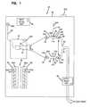
- FIG. 1shows an example fiber distribution hub (FDH) 20 having a component identification element in accordance with the principles of the present disclosure.
- the fiber distribution hub 20includes an outer housing 22 .
- An FDH identifying element 22 Ais provided on the housing 22 .
- the identifying element 22 Ais an RFID tag or a bar code.
- the RFID tagcan include various embedded information such as a photo of the FDH, an installation manual, information regarding FDH accessories, reorder information, and a specific identifying number for identifying the particular FDH.
- the FDH 20includes a termination field/panel 24 supporting a plurality of fiber optic adapters 26 .
- Each of the fiber optic adapters 26includes first and second ports 28 , 30 .
- the termination field 24has an identifying element 24 A corresponding to the field as a whole.
- each of the fiber optic adapters 26includes identifying elements corresponding to each of the first and second ports 28 , 30 .
- each of the first ports 28includes its own identifying element 28 A and each of the second ports includes its own identifying element 28 A.
- the FDH 20also includes a splitter module 32 containing a splitting component, such as power splitter or wave length splitter components.
- the splitting module 32has its own identifying element 32 A.
- the splitting module 32includes a plurality of outputs 34 (e.g., 16 pigtail outputs, 32 pigtail outputs, etc.). Each of the outputs 34 can include its own identifying element 34 A. If the outputs 34 are connectorized, the identifying elements 34 A can be provided on connectors 35 terminated to the ends of the outputs 34 . If the outputs 34 are not connectorized, the identifying elements 34 A can be provided directly on the pigtails routed out from the splitter module 32 .
- the splitter module 32can also include an input 36 which can have its own identifying element 36 A.
- the input 36can be connectorized or connectorized.
- the identifying element 36 Acan be provided on the connector.
- the splitter moduleincludes components for providing a one to many optical connection.
- a signal input to the splitter module 32 by the input 36is split in power and divided equally to the various outputs 34 .
- a splitting component in the form of a wave length division multiplexera signal input through the input 36 is split or divided based on wave length and signals within predefined wave length ranges are transmitted to the various outputs 34 .
- the FDH 20also includes a plurality of optical fibers 40 having ends that are connectorized by connectors 42 .
- the optical fibers 40can be optically connected to various subscriber locations via distribution or drop cables.
- Each of the connectors 42can include its own identifying element 42 A.
- the outputs 34 of the splitting module 32can be plugged into the first ports 28 of the fiber optic adapters 26 and the connectors 42 corresponding to the optical fibers 40 can be inserted into the second ports 30 of the fiber optic adapters 26 .
- the fiber optic adapters 26are used to optically connect the outputs 34 of the splitter module 32 to the optical fibers 40 . This allows subscribers to be optically connected to the fiber optic network.
- the identifying elements corresponding to the fiber optic connectorscan include various information about the connectors.
- Example informationincludes: a unique identification number; test results from final factory validation testing (e.g., end face geometry, insertion loss information, return loss information), warranty information, installation information, accessories information, re-order information, or other information.
- the FDH 20can include a splicing region 48 including one or more splice trays.
- Each of the splice trayscan include its own identifying element. It will be appreciated that splices are held within the splice tray. It will be appreciated that each of the splices can have its own identifying element. Similarly, each of the fibers connected by a given splice can have there own identifying element.
- the splicing region 48can be used to splice the fibers 40 to outgoing distribution cables routed to subscriber locations.
- a further splice region 49can be provided for splicing the feeder fibers to the splitter inputs. Identifiers can be provided at each of the splice trays and can also be provided for each of the incoming and outgoing fibers routed to the spliced trays.
- the FDH 20also includes a connector storage location 60 having parking modules 62 with module identifiers 62 A.
- the parking modulesinclude ports/receptacles 64 for receiving individual connectors (e.g., connectors 35 ).
- the modules and each of the portscan include individual identifying elements 64 A.
- the FDH 20is installed by a technician in the field.
- a techniciancan use a handheld scanner to scan the FDH identifying element 22 A.
- the scanning elementcan also access positioning data (e.g., global positioning coordinates) corresponding to the location the FDH 20 is being installed.
- positioning datae.g., global positioning coordinates
- Scanning of the identifying element 22 Acan also provide the technician with necessary installation information, such as installation manuals or other materials.
- the scanningties a unique identifying number assigned to the FDH 20 with a particular geographic position at which the FDH 20 has been installed.
- Information relating to the techniciane.g., identification, training record
- the technicianplugs the outputs 34 into the first ports 28 and also plugs the connectors 42 into the second ports 30 .
- the techniciancan scan the identifying elements 34 A corresponding to the splitter outputs and the identifying elements 28 A corresponding to the first port. In this way, information can be saved into the as-built database showing exactly which outputs 34 are plugged into exactly which first ports 28 .
- specific identifying numbers corresponding to each of the outputs 34are tied to corresponding identifying numbers corresponding to each of the first ports 28 .
- the identifying elements 34 A and the identifying elements 28 Aare scanned separately.
- the identifying elements 34 A and the identifying elements 28 Aare required to be scanned together or can be scanned together to reduce the likelihood of error in the scanning process.
- the techniciancan scan each of the identifying elements 42 A and each of the identifying elements 30 A to record a record of exactly which connectors 42 are inserted into which second ports 30 .
- identification numbers corresponded to each of the connectors 42are linked to corresponding identification numbers corresponding to each of the second ports 30 so that an accurate as-built data base can be generated.
- information linking specific storage ports 64 to specific outputs 34can be scanned and saved.
- the scanner/RFID readercan be a separate piece of equipment. In other embodiments, the scanner/RFID reader can be incorporated into a cellular phone or tablet, or can be an add-on to a cellular phone or tablet. Other information that can be recorded includes: the name of the technician conducting the installation; technician training records; and the time at which each operation was conducted.
- Example information that can be included in the identification elementse.g., RFID tags which would be available to the customer/technician upon accessing the information on the identification element include:
- Scanning the identification elementscan generate the following information:
- At least some of the information outlined abovecan be used for implementing product warranties.
- warrantiescould be started by the product seller when the product is actually installed in the field.
- the information derived from the scanning operationcan be used to confirm that all product was be installed by a certified installer and suitably scanned upon installation. Violation of this could void the warranty.
- An applicatione.g., a Smartphone application
- An applicationcan be developed that verifies training records of installer, records installation location; determines installation rate used an input to demand prediction, as a locator for any warranty concerns; and to bring extended warranty information to customers as records indicate warranty runs out. Registered users can become part of a seller database of customer contacts—allows follow-up on ease of use.
- the above-descriptionincludes an example implementation of component identification elements included in a fiber distribution hub (FDH) 20 .
- FDHfiber distribution hub
- Various other telecommunications equipment and cable management systems and networksare anticipated for use with one or more component identification elements.
- the identifying elementscan be utilized in a data center including an identifying element associated with each patch panel. Identifying elements can be associated with each port of the patch panel and each patch cord connected to the patch panel if desired. Fiber or copper cables can be used in the data center.
- One example copper patch panelis disclosed in U.S. Pat. No. 6,504,726 which is hereby incorporated by reference in its entirety.
- an identifying elementwhich is useful in a data center, on a fiber distribution hub, or in other telecommunications systems and networks, is a 2d bar code in the form of a QR code.
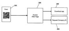
- the QR codecan be scanned at step 202 by a handheld device (e.g., cell phone) by the technician, which can then direct the technician to a company's website at step 204 .
- the company's websitecan be the product manufacturer's website or the user's website.
- the QR codecan also link to one or more of the items in the Information List No. 1 above.
- the QR codecould also be coded to include one or more of the items in the Information List No. 1 above.
- the QR codecan also direct the technician to download an application for use with the handheld device in managing the telecommunications equipment at step 206 .
- the techniciandownloads the application, the technician can also request or enter a company identification code and/or user specific identification code at step 208 .
- the QR code 100 of the network devicee.g., patch panel
- the techniciancan enter the company ID, and the password if necessary, at step 302 , to begin implementation of the application.
- the handheld deviceis already linked to the user, the user can begin the application to manage the network device at step 304 .
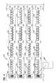
- the QR codegives the technician a tool to maintain connection information for their network connections in a data center, such as the network connections between patch panels 120 , of the type shown in FIG. 4 . Instead of scanning all of the connections, the technician can enter them manually into the handheld device to document the network connections.
- Each patch panel 120will be labeled with a unique QR code 100 .
- the QR codewill contain a URL and a unique ID.
- the URLwill bring the technician to a website where the technician can see installation instructions or other information about the network.
- the applicationwill give the technician the possibility to maintain the port 122 connections for all the patch panels 120 adjacent to the scanned panel 120 .
- the applicationpreferably requests a company identification and a password at step 302 of FIG. 3 .
- the technicianwill be able to identify the panel at step 304 .
- the panel informationcan include information such as: 1) a room number, 2) a row number, 3) a rack number, and 4) a panel number as shown in steps 306 and 308 . Together with the unique ID, and the QR code of the panel, this information will be stored locally on the handheld device. This information can be uploaded to the network or main storage device.
- the technicianwhen the technician reads the QR code on the patch panel 120 , the technician will see the port information on the handheld device.
- the port informationcan be updated if the technician makes a change in the connections between the ports 122 at step 310 . Scanning the QR code and/or updating the information can update the items in the Information List No. 2 above.
- the techniciancan view existing connections between ports 122 to make a manual check and verification of the connections.
- the techniciancan also synchronize the handheld device with other handheld devices and also to the home network database so that the full network information is current.
- a further application of the component identification and tracking system for telecommunication networksincludes situations where internet and/or cell service is unavailable.
- the techniciancan utilize the QR code to access information stored on a handheld device. If the technician then makes changes to the network connections, the information can be entered on the handheld device and later synchronized with the main network or other handheld devices for updating the main database.
- a still further application of the present inventionincludes situations where the QR code includes the actual connection data of the network connections. Such information might be useful when there is no internet or cell coverage where the technician is accessing the network. If the technician reads the QR code and reads the network connections, the technician is able to see a current status of the network connections. If a change is made by the technician, the technician can enter the change on the handheld device, and print out a new QR code on a portable printer. The new QR code is left on the network device, and the previous code is removed or covered up since it is now out-of-date. In this manner, a technician can access network information merely by reading the QR code, and updating the QR code to reflect changes.
- various passive identification elementscan be utilized including the noted barcodes and the radio frequency identification (RFID) tags.
- Barcodescan be one dimensional or two dimensional. More information is capable of being stored on the two dimensional bar codes, such as the noted QR codes. The information can be transferred to other network devices for network management, especially for larger networks where multiple technicians may be managing the network connections.
- RFIDradio frequency identification
Landscapes
- Engineering & Computer Science (AREA)
- Databases & Information Systems (AREA)
- Theoretical Computer Science (AREA)
- Physics & Mathematics (AREA)
- General Physics & Mathematics (AREA)
- Computer Networks & Wireless Communication (AREA)
- Data Mining & Analysis (AREA)
- General Engineering & Computer Science (AREA)
- Signal Processing (AREA)
- Optics & Photonics (AREA)
- Light Guides In General And Applications Therefor (AREA)
- Telephonic Communication Services (AREA)
- Information Transfer Between Computers (AREA)
Abstract
Description
- Test results (IL, RL, geometry, etc.)
- User manuals and videos
- Re-order information
- Ancillary products
- Product pricing and availability
- Warranty information
- Product recall notices
- Extended warranty offers
- LSL information
- Installation date and technician
- Installation rates—actual consumption
- End user information
- Installation locations—GPS coordinates
- Actual installer name and training records
- Verify improper use of LSL items
- Frequency of use/visit
- Automated record keeping
- 20 fiber distribution hub
- 22 outer housing
- 22A identifying element
- 24 termination field/panel
- 24A identifying element
- 24 splitter module
- 26 fiber optic adapters
- 28 first ports
- 28A identifying element
- 30 second ports
- 30A identifying elements
- 32 splitter module
- 32A identifying element
- 34 outputs
- 34A identifying element
- 35 connectors
- 36 input
- 36A identifying element
- 40 optical fibers
- 42 connectors
- 42A identifying element
- 48 splicing region
- 49 splice region
- 60 connector storage location
- 62 parking modules
- 62A module identifiers
- 64 ports/receptacles
- 64A individual identifying elements
- 100 identifying element
- 110 data center
- 120 patch panel
- 122 port
- 200 handheld device
- 202-208 initiation steps
- 302-310 usage steps
Claims (16)
Priority Applications (1)
| Application Number | Priority Date | Filing Date | Title |
|---|---|---|---|
| US14/116,666US9064022B2 (en) | 2011-05-17 | 2012-05-16 | Component identification and tracking system for telecommunication networks |
Applications Claiming Priority (4)
| Application Number | Priority Date | Filing Date | Title |
|---|---|---|---|
| US201161487178P | 2011-05-17 | 2011-05-17 | |
| US201261591576P | 2012-01-27 | 2012-01-27 | |
| PCT/US2012/038152WO2012158806A2 (en) | 2011-05-17 | 2012-05-16 | Component identification and tracking systems for telecommunication networks |
| US14/116,666US9064022B2 (en) | 2011-05-17 | 2012-05-16 | Component identification and tracking system for telecommunication networks |
Related Parent Applications (1)
| Application Number | Title | Priority Date | Filing Date |
|---|---|---|---|
| PCT/US2012/038152A-371-Of-InternationalWO2012158806A2 (en) | 2011-05-17 | 2012-05-16 | Component identification and tracking systems for telecommunication networks |
Related Child Applications (1)
| Application Number | Title | Priority Date | Filing Date |
|---|---|---|---|
| US14/712,536ContinuationUS20160042085A1 (en) | 2011-05-17 | 2015-05-14 | Component identification and tracking system for telecommunication networks |
Publications (2)
| Publication Number | Publication Date |
|---|---|
| US20140061297A1 US20140061297A1 (en) | 2014-03-06 |
| US9064022B2true US9064022B2 (en) | 2015-06-23 |
Family
ID=47177608
Family Applications (2)
| Application Number | Title | Priority Date | Filing Date |
|---|---|---|---|
| US14/116,666ActiveUS9064022B2 (en) | 2011-05-17 | 2012-05-16 | Component identification and tracking system for telecommunication networks |
| US14/712,536AbandonedUS20160042085A1 (en) | 2011-05-17 | 2015-05-14 | Component identification and tracking system for telecommunication networks |
Family Applications After (1)
| Application Number | Title | Priority Date | Filing Date |
|---|---|---|---|
| US14/712,536AbandonedUS20160042085A1 (en) | 2011-05-17 | 2015-05-14 | Component identification and tracking system for telecommunication networks |
Country Status (3)
| Country | Link |
|---|---|
| US (2) | US9064022B2 (en) |
| EP (1) | EP2710517A4 (en) |
| WO (1) | WO2012158806A2 (en) |
Cited By (10)
| Publication number | Priority date | Publication date | Assignee | Title |
|---|---|---|---|---|
| US20150341111A1 (en)* | 2014-05-21 | 2015-11-26 | Hitachi Metals, Ltd. | Communication light detector |
| US11150417B2 (en) | 2019-09-06 | 2021-10-19 | Coming Research & Development Corporation | Systems and methods for estimating insertion loss in optical fiber connections and fiber links using data reading apparatus |
| US20220074810A1 (en)* | 2020-09-10 | 2022-03-10 | Exfo Inc. | Optical fiber endface inspection microscope having adapter tip detection and autoconfiguration |
| US11295135B2 (en)* | 2020-05-29 | 2022-04-05 | Corning Research & Development Corporation | Asset tracking of communication equipment via mixed reality based labeling |
| US11347955B2 (en) | 2020-03-09 | 2022-05-31 | Panduit Corp. | Cable management system and method |
| US11374808B2 (en)* | 2020-05-29 | 2022-06-28 | Corning Research & Development Corporation | Automated logging of patching operations via mixed reality based labeling |
| US12186241B2 (en) | 2021-01-22 | 2025-01-07 | Hill-Rom Services, Inc. | Time-based wireless pairing between a medical device and a wall unit |
| US12197997B2 (en) | 2020-03-09 | 2025-01-14 | Panduit Corp. | Cable management system and method |
| US12279999B2 (en) | 2021-01-22 | 2025-04-22 | Hill-Rom Services, Inc. | Wireless configuration and authorization of a wall unit that pairs with a medical device |
| US12399794B2 (en) | 2022-04-14 | 2025-08-26 | Panduit Corp. | Infrastructure management system and method |
Families Citing this family (13)
| Publication number | Priority date | Publication date | Assignee | Title |
|---|---|---|---|---|
| EP2735976A1 (en)* | 2012-11-22 | 2014-05-28 | ThePeople.de GmbH | Code-based information system |
| US9959190B2 (en)* | 2013-03-12 | 2018-05-01 | International Business Machines Corporation | On-site visualization of component status |
| US8887993B2 (en) | 2013-04-23 | 2014-11-18 | The Boeing Company | Barcode access to electronic resources for complex system parts |
| US9098593B2 (en)* | 2013-04-23 | 2015-08-04 | The Boeing Company | Barcode access to electronic resources for lifecycle tracking of complex system parts |
| ITRM20140076U1 (en)* | 2014-05-20 | 2015-11-20 | Cis Sud Srl | SYSTEM OF CONSTITUTION AND / OR DOCUMENT UPDATING OF THE STRUCTURE OF A TELEPHONE NETWORK, IN PARTICULAR A FIBER OPTIC NETWORK. |
| WO2016099848A1 (en)* | 2014-12-18 | 2016-06-23 | 3M Innovative Properties Company | Portable reader device for reading miniaturized two dimensional identification codes |
| US10096269B2 (en) | 2014-12-18 | 2018-10-09 | Corning Research & Development Corporation | Identification tag |
| CN105224968A (en)* | 2015-09-25 | 2016-01-06 | 巫立斌 | A kind of electronic vehicle license plate system |
| US9912781B2 (en) | 2015-09-29 | 2018-03-06 | International Business Machines Corporation | Customized electronic product configuration |
| US10776887B2 (en)* | 2017-02-07 | 2020-09-15 | Enseo, Inc. | System and method for making reservations in a hospitality establishment |
| WO2018165146A1 (en) | 2017-03-06 | 2018-09-13 | Cummins Filtration Ip, Inc. | Genuine filter recognition with filter monitoring system |
| EP3776748A4 (en)* | 2018-03-29 | 2022-01-26 | CommScope Technologies LLC | SIGNS AND METHODS OF IDENTIFICATION OF TELECOMMUNICATIONS COMPONENTS |
| US11847093B2 (en)* | 2021-04-26 | 2023-12-19 | Thomas C Lee | System and method for managing a plurality of data storage devices |
Citations (189)
| Publication number | Priority date | Publication date | Assignee | Title |
|---|---|---|---|---|
| US3243761A (en) | 1963-10-08 | 1966-03-29 | Burndy Corp | Contact locking connector |
| USRE26692E (en) | 1967-09-07 | 1969-10-14 | Contact for direct reception of printed circuit board | |
| US3954320A (en) | 1973-07-06 | 1976-05-04 | Western Electric Company, Inc. | Electrical connecting devices for terminating cords |
| US4127317A (en) | 1976-07-06 | 1978-11-28 | Bunker Ramo Corporation | Electrical connectors which may be shortened to provide fewer contacts |
| US4679879A (en) | 1986-10-03 | 1987-07-14 | Molex Incorporated | Plug and receptacle connector assembly |
| US4684245A (en) | 1985-10-28 | 1987-08-04 | Oximetrix, Inc. | Electro-optical coupler for catheter oximeter |
| US4737120A (en) | 1986-11-12 | 1988-04-12 | Amp Incorporated | Electrical connector with low insertion force and overstress protection |
| US4953194A (en) | 1989-09-22 | 1990-08-28 | Network Devices, Incorporated | Automated documentation system for a communications network |
| US4968929A (en) | 1987-04-18 | 1990-11-06 | Heidelberger Druckmaschinen Ag | Plug connector coding system for electric cables |
| US4978310A (en) | 1989-01-17 | 1990-12-18 | Hosiden Electronics Co., Ltd. | Electrical jack connector |
| GB2236398A (en) | 1989-09-29 | 1991-04-03 | James Alexander Carter | Self documenting patch panel |
| US5041005A (en) | 1991-02-10 | 1991-08-20 | Amp Incorporated | Low profile cam-in SIMM socket |
| US5052940A (en) | 1990-05-11 | 1991-10-01 | Rit-Rad Interconnection Technologies Ltd. | Hermaphroditic self-shorting electrical connector |
| US5064381A (en) | 1991-03-04 | 1991-11-12 | Lin Yu Chuan | Electric connecting device |
| US5107532A (en) | 1989-09-22 | 1992-04-21 | Cable Management International, Inc. | Automated documentation system for a communications network |
| US5161988A (en) | 1991-02-13 | 1992-11-10 | Rit Technologies Ltd. | Patching panel |
| US5166970A (en) | 1991-06-10 | 1992-11-24 | Ward Timothy K | Multi-conductor identifier with voice communication capability |
| US5199895A (en) | 1992-02-04 | 1993-04-06 | Chang Lien Ker | Low insertion force, self-locking connecting apparatus for electrically connecting memory modules to a printed circuit board |
| US5222164A (en) | 1992-08-27 | 1993-06-22 | International Business Machines Corporation | Electrically isolated optical connector identification system |
| US5265187A (en) | 1992-10-28 | 1993-11-23 | Northern Telecom Limited | Distribution frame and optical connector holder combination |
| US5305405A (en) | 1993-02-25 | 1994-04-19 | Adc Telecommunications, Inc. | Patch cord |
| US5353367A (en) | 1993-11-29 | 1994-10-04 | Northern Telecom Limited | Distribution frame and optical connector holder combination |
| US5394503A (en) | 1993-10-08 | 1995-02-28 | Data Switch Corporation | Optical fiber connection monitoring apparatus, patch panel control system and method of using same |
| US5393249A (en) | 1993-06-30 | 1995-02-28 | Adc Telecommunications, Inc. | Rear cross connect DSX system |
| US5413494A (en) | 1992-10-05 | 1995-05-09 | Adc Telecommunications, Inc. | Jack module assembly |
| US5415570A (en) | 1992-12-28 | 1995-05-16 | At&T Corp. | Modular connector with contacts associated with more than one surface |
| US5418334A (en) | 1993-08-04 | 1995-05-23 | Williams; Kenyon D. | Relative position tracer lamp indicator |
| US5419717A (en) | 1994-08-15 | 1995-05-30 | The Whitaker Corporation | Hybrid connector between optics and edge card |
| US5448675A (en) | 1994-06-09 | 1995-09-05 | At&T Ipm Corp. | Telecommunications distribution frame with tracing |
| US5467062A (en) | 1992-04-02 | 1995-11-14 | Adc Telecommunications, Inc. | Miniature coax jack module |
| US5470251A (en) | 1993-09-24 | 1995-11-28 | Molex Incorporated | Connector engagement detecting device |
| US5473715A (en) | 1994-05-03 | 1995-12-05 | Methode Electronics, Inc. | Hybrid fiber optic/electrical connector |
| US5483467A (en) | 1992-06-10 | 1996-01-09 | Rit Technologies, Ltd. | Patching panel scanner |
| US5579425A (en) | 1995-08-30 | 1996-11-26 | Lucent Technologies Inc. | Anti-snag duplex connector |
| US5660567A (en) | 1995-11-14 | 1997-08-26 | Nellcor Puritan Bennett Incorporated | Medical sensor connector with removable encoding device |
| US5674085A (en) | 1996-05-24 | 1997-10-07 | The Whitaker Corporation | Electrical connector with switch |
| US5685741A (en) | 1996-06-27 | 1997-11-11 | Adc Telecommunications, Inc. | On demand plug-in jack card and monitor frame |
| US5712942A (en) | 1996-05-13 | 1998-01-27 | Lucent Technologies Inc. | Optical communications system having distributed intelligence |
| US5764043A (en) | 1996-12-20 | 1998-06-09 | Siecor Corporation | Traceable patch cord and connector assembly and method for locating patch cord ends |
| US5800192A (en) | 1996-08-30 | 1998-09-01 | Berg Technology, Inc. | Receptacle with integral sensor device |
| US5821510A (en) | 1994-12-22 | 1998-10-13 | Lucent Technologies Inc. | Labeling and tracing system for jumper used in an exchange |
| US5854824A (en) | 1994-09-04 | 1998-12-29 | Rit Technologies Ltd. | Connectivity scanner |
| US5871368A (en) | 1996-11-19 | 1999-02-16 | Intel Corporation | Bus connector |
| US5910776A (en) | 1994-10-24 | 1999-06-08 | Id Technologies, Inc. | Method and apparatus for identifying locating or monitoring equipment or other objects |
| US6002331A (en) | 1998-07-20 | 1999-12-14 | Laor; Herzel | Method and apparatus for identifying and tracking connections of communication lines |
| US6079996A (en) | 1999-04-15 | 2000-06-27 | Lucent Technologies Inc. | Selectable compatibility electrical connector jack |
| US6095851A (en) | 1997-11-17 | 2000-08-01 | Xircom, Inc. | Status indicator for electronic device |
| US6116961A (en) | 1998-11-12 | 2000-09-12 | Adc Telecommunications, Inc. | Jack assembly |
| WO2000065696A1 (en) | 1999-04-23 | 2000-11-02 | The Whitaker Corporation | Receptacle connector with plug differentiation member |
| US6222975B1 (en) | 1998-12-11 | 2001-04-24 | Lucent Technologies, Inc. | System and method for detecting and reporting the use of optical fibers in fiber optic cables |
| US6222908B1 (en) | 1999-09-23 | 2001-04-24 | Avaya Technology Corp. | Method and device for identifying a specific patch cord connector as it is introduced into, or removed from, a telecommunications patch system |
| US6227911B1 (en) | 1998-09-09 | 2001-05-08 | Amphenol Corporation | RJ contact/filter modules and multiport filter connector utilizing such modules |
| US6234830B1 (en) | 1999-02-10 | 2001-05-22 | Avaya Technology Corp. | Tracing interface module for patch cords in a telecommunications system |
| US6238235B1 (en) | 1999-05-10 | 2001-05-29 | Rit Technologies Ltd. | Cable organizer |
| US6280231B1 (en) | 1998-07-24 | 2001-08-28 | Krone Aktiengesellschaft | Electrical connector |
| US6285293B1 (en) | 1999-02-10 | 2001-09-04 | Avaya Technology Corp. | System and method for addressing and tracing patch cords in a dedicated telecommunications system |
| US6300877B1 (en) | 2000-03-10 | 2001-10-09 | Adc Telecommunications, Inc. | DSX baytracer illuminator |
| US6330148B1 (en) | 1999-01-13 | 2001-12-11 | Lg. Philips Lcd Co., Ltd. | Flat panel display module for computer |
| US6330307B1 (en) | 1999-02-10 | 2001-12-11 | Avaya Technology Corp. | Display panel overlay structure and method for tracing interface modules in a telecommunications patch system |
| US20020008613A1 (en) | 2000-02-11 | 2002-01-24 | Nathan John F. | Electrical connector for vehicle wiring |
| US6350148B1 (en) | 1999-02-10 | 2002-02-26 | Avaya Technology Corp. | Method and device for detecting the presence of a patch cord connector in a telecommunications patch system |
| US6364694B1 (en) | 2001-01-19 | 2002-04-02 | M M E Corporation | Modular communications socket |
| EP1199586A2 (en) | 2000-10-18 | 2002-04-24 | Lucent Technologies Inc. | Optical fiber cable tracing system |
| WO2002047215A1 (en) | 2000-12-06 | 2002-06-13 | Barkey, Volker | Electrical device |
| US6409392B1 (en) | 1999-10-19 | 2002-06-25 | Fitel Usa Corp. | Duplex clip for clipping two optical fiber simplex connectors together to form a duplex connector |
| US20020081076A1 (en) | 2000-12-27 | 2002-06-27 | Lampert Norman R. | Optical connector receptacle having switching capability |
| US6421322B1 (en) | 1997-11-17 | 2002-07-16 | Adc Telecommunications, Inc. | System and method for electronically identifying connections of a cross-connect system |
| US6422895B1 (en) | 2001-04-17 | 2002-07-23 | M M E Corporation | Receptacle for telephone plug and wide-band cable plug |
| US6424710B1 (en) | 1999-02-10 | 2002-07-23 | Avaya Technology Corp. | Method and device for detecting the presence of a patch cord connector in a telecommunications patch system using passive detection sensors |
| US6437894B1 (en) | 1998-12-11 | 2002-08-20 | Fitel Usa Corp. | Fiber distribution shelf assembly for a fiber administration system having integral line tracing capabilities |
| EP1237024A1 (en) | 2001-02-15 | 2002-09-04 | FITEL USA CORPORATION (a Delaware Corporation) | Optical connector receptacle having electrical switching capability |
| USD466479S1 (en) | 2000-05-25 | 2002-12-03 | Krone Gmbh | RJ style plug |
| US6499861B1 (en) | 1999-09-23 | 2002-12-31 | Avaya Technology Corp. | Illuminated patch cord connector ports for use in a telecommunications patch closet having patch cord tracing capabilities |
| US6522737B1 (en) | 1999-02-10 | 2003-02-18 | Avaya Technology Corp. | System and method of operation for a telecommunications patch system |
| US6574586B1 (en) | 1999-04-06 | 2003-06-03 | Itracs Corporation | System for monitoring connection pattern of data ports |
| US6612856B1 (en) | 2001-12-17 | 2003-09-02 | 3Com Corporation | Apparatus and methods for preventing cable-discharge damage to electronic equipment |
| US6626697B1 (en) | 2002-11-07 | 2003-09-30 | Tyco Electronics Corp. | Network connection sensing assembly |
| US6684179B1 (en) | 1999-04-06 | 2004-01-27 | Itracs Corporation | System for monitoring connection pattern of data ports |
| DE10244304B3 (en) | 2002-09-23 | 2004-03-18 | Data-Complex E.K. | Arrangement for monitoring patch panels at distributor points in data networks has patch cables that can be plugged into connections in patch fields with plugs, each fitted with a transponder |
| US20040052498A1 (en) | 2002-09-13 | 2004-03-18 | Colombo Bruce A. | Adapter systems for dynamically updating information related to a network and methods for developing the adapter systems |
| US20040052471A1 (en) | 2002-09-13 | 2004-03-18 | Fitel Usa Corp. | Connector systems for dynamically updating information related to a network and methods for developing the connector systems |
| GB2393549A (en) | 2002-09-25 | 2004-03-31 | Cormant Technologies Inc | Use of machine-readable identifiers to manage a structured cabling system |
| US6743044B2 (en) | 2002-08-14 | 2004-06-01 | Adc Telecommunications, Inc. | Cross-connect jumper assembly having tracer lamp |
| US20040117515A1 (en) | 2002-11-15 | 2004-06-17 | Masuyuki Sago | Distributing system |
| US6793408B2 (en) | 2002-12-31 | 2004-09-21 | Intel Corporation | Module interface with optical and electrical interconnects |
| US6802735B2 (en) | 2002-06-18 | 2004-10-12 | Tyco Electronics Corporation | Receptacle and plug interconnect module with integral sensor contacts |
| EP1467232A1 (en) | 2002-01-15 | 2004-10-13 | Tokyo Communication Equipment Mfg. Co., Ltd. | Optical connector having memory function |
| US6808116B1 (en) | 2002-05-29 | 2004-10-26 | At&T Corp. | Fiber jumpers with data storage method and apparatus |
| US6811446B1 (en) | 2003-10-08 | 2004-11-02 | Speed Thch Corp. | Combination connector shell |
| US6814624B2 (en) | 2002-11-22 | 2004-11-09 | Adc Telecommunications, Inc. | Telecommunications jack assembly |
| US20040240807A1 (en) | 2001-05-30 | 2004-12-02 | Franz-Friedrich Frohlich | Optical distribution device and light waveguide connector cable |
| US6847856B1 (en) | 2003-08-29 | 2005-01-25 | Lucent Technologies Inc. | Method for determining juxtaposition of physical components with use of RFID tags |
| US6850685B2 (en) | 2002-03-27 | 2005-02-01 | Adc Telecommunications, Inc. | Termination panel with pivoting bulkhead and cable management |
| US6890197B2 (en) | 2003-02-13 | 2005-05-10 | Gateway, Inc. | RJ-45 jack with RJ-11 detection |
| US6932517B2 (en) | 2000-10-27 | 2005-08-23 | Ethicon Endo-Surgery, Inc. | Connector incorporating a contact pad surface on a plane parallel to a longitudinal axis |
| US6939168B2 (en) | 2001-07-06 | 2005-09-06 | Fci Americas Technology, Inc. | Universal serial bus electrical connector |
| USD510068S1 (en) | 2002-03-11 | 2005-09-27 | Rit Technologies Ltd | Patch panel for communication equipment |
| US6961675B2 (en) | 2000-03-14 | 2005-11-01 | Itracs Corporation | System for monitoring connection pattern of data ports |
| US20050249477A1 (en) | 2004-05-04 | 2005-11-10 | Mark Parrish | Optical fiber connectors with identification circuits and distribution terminals that communicate therewith |
| US6968994B1 (en) | 2004-07-06 | 2005-11-29 | Nortel Networks Ltd | RF-ID for cable management and port identification |
| US6971895B2 (en) | 2002-11-15 | 2005-12-06 | Tokyo Communication Equipment Mfg Co., Ltd. | Connector adapter with memory function unit |
| US6976867B2 (en) | 2002-11-07 | 2005-12-20 | Tyco Electronics Amp Espana, S.A. | Network connection sensing assembly |
| DE102004033940A1 (en) | 2004-07-14 | 2006-02-16 | Tkm Telekommunikation Und Elektronik Gmbh | Connector identification system for identifying multi-pole plug-in connectors for data-transmission cables in panels with manifold sockets has detectors/LEDs assigned to individual sockets |
| EP1662287A1 (en) | 2004-10-27 | 2006-05-31 | Panduit Corporation | Fiber optic industrial connector |
| US20060148279A1 (en)* | 2004-12-06 | 2006-07-06 | Commscope Solutions Properties, Llc | Telecommunications patching system that utilizes RFID tags to detect and identify patch cord interconnections |
| US7077710B2 (en) | 2001-03-21 | 2006-07-18 | Rit Technologies Ltd. | Patch panel |
| US20060160395A1 (en) | 2004-12-21 | 2006-07-20 | Commscope Solutions Properties, Llc | Methods, systems and computer program products for connecting and monitoring network equipment in a telecommunications system |
| US7081808B2 (en) | 2002-09-13 | 2006-07-25 | Fitel Usa Corp. | Self-registration systems and methods for dynamically updating information related to a network |
| US7088880B1 (en) | 2003-12-24 | 2006-08-08 | Lockheed Martin Corporation | Optical fiber coupling and inline fault monitor device and method |
| US20060193591A1 (en) | 2003-12-23 | 2006-08-31 | Adc Telecommunications, Inc. | High density optical fiber distribution frame with modules |
| US7112090B2 (en) | 2003-05-14 | 2006-09-26 | Panduit Corp. | High density keystone jack patch panel |
| US20060228086A1 (en) | 2005-03-31 | 2006-10-12 | Matthew Holmberg | Adapter block including connector storage |
| US7153142B2 (en) | 2002-11-11 | 2006-12-26 | Rit Technologies Ltd. | Retrofit kit for interconnect cabling system |
| US7165728B2 (en) | 2004-04-02 | 2007-01-23 | Stratos International, Inc. | Radio frequency identification for transfer of component information in fiber optic testing |
| US7193422B2 (en) | 2004-01-20 | 2007-03-20 | The Siemon Company | Patch panel system |
| US7207819B2 (en) | 2005-09-09 | 2007-04-24 | Hon Hai Precision Ind. Co., Ltd. | Electrical connector with a detective switch |
| US20070116411A1 (en) | 2005-11-18 | 2007-05-24 | Mark Benton | Transceiver/fiber optic connector adaptor with patch cord id reading capability |
| US7234944B2 (en) | 2005-08-26 | 2007-06-26 | Panduit Corp. | Patch field documentation and revision systems |
| US7241157B2 (en) | 2004-04-09 | 2007-07-10 | Hon Hai Precision Ind. Co., Ltd. | Modular jack with a detective switch |
| US20070176745A1 (en) | 2006-01-30 | 2007-08-02 | Telect, Inc. | Telecom Equipment With RFIDs |
| US20070237470A1 (en) | 2006-04-10 | 2007-10-11 | Aronson Lewis B | Active optical cable with electrical connector |
| US20070254529A1 (en) | 2006-04-26 | 2007-11-01 | Tyco Electronics Corporation | Electrical connector having contact plates |
| US7297018B2 (en) | 2004-11-03 | 2007-11-20 | Panduit Corp. | Method and apparatus for patch panel patch cord documentation and revision |
| US7312715B2 (en) | 2003-07-31 | 2007-12-25 | Rit Technologies Ltd. | Management of large scale cabling systems |
| US7315224B2 (en) | 2001-08-23 | 2008-01-01 | Rit Technologies Ltd. | High data rate interconnecting device |
| USD559186S1 (en) | 2004-09-20 | 2008-01-08 | Rit Technologies Ltd. | High-density patch panel |
| KR20080015345A (en) | 2006-08-14 | 2008-02-19 | 김용표 | Information Recognition Device Using 2D Barcode |
| US7352285B2 (en) | 2004-09-03 | 2008-04-01 | Hitachi, Ltd. | IC tag mounting on a harness and harness mounting method |
| US7352289B1 (en) | 2003-09-11 | 2008-04-01 | Sun Microsystems, Inc. | System and method for detecting the connection state of a network cable connector |
| US7356208B2 (en) | 2006-05-03 | 2008-04-08 | Biolase Technology, Inc. | Fiber detector apparatus and related methods |
| US20080090454A1 (en) | 2006-10-10 | 2008-04-17 | Adc Telecommunications, Inc. | Upgradeable patch panel |
| US20080090450A1 (en) | 2004-12-22 | 2008-04-17 | Matsushita Electric Works, Ltd. | Optical And Eletrical Compound Connector |
| US20080100456A1 (en) | 2006-10-31 | 2008-05-01 | Downie John D | System for mapping connections using RFID function |
| US20080100467A1 (en) | 2006-10-31 | 2008-05-01 | Downie John D | Radio frequency identification of component connections |
| US7370106B2 (en) | 2000-11-22 | 2008-05-06 | Panduit Corp. | Network revision system with local system ports |
| US7374101B2 (en) | 2004-02-20 | 2008-05-20 | Hitachi Maxell, Ltd. | Adapter panel, electronic equipment, and cable connector identification system |
| US7384300B1 (en) | 1999-12-22 | 2008-06-10 | Xerox Corporation | Method and apparatus for a connection sensing apparatus |
| US7396245B2 (en) | 2006-10-13 | 2008-07-08 | Cheng Uei Precision Industry Co., Ltd. | Memory card connector |
| US20080175532A1 (en) | 2007-01-16 | 2008-07-24 | Reichle & De-Massari Ag | Plug connector system and protective device for optical plug connectors |
| US20080175550A1 (en) | 2007-01-19 | 2008-07-24 | Hutch Coburn | Fiber optic adapter cassette and panel |
| US20080200160A1 (en)* | 2006-09-28 | 2008-08-21 | Dudley Fitzpatrick | Apparatuses, Methods and Systems for Ambiguous Code-Triggered Information Querying and Serving on Mobile Devices |
| US20080250122A1 (en) | 2006-11-06 | 2008-10-09 | Ikan Technologies, Inc. | Methods and systems for network configuration |
| US7458517B2 (en) | 2004-04-02 | 2008-12-02 | Stratos International, Inc. | Radio frequency identification of a connector by a patch panel or other similar structure |
| US7481681B2 (en) | 2004-04-06 | 2009-01-27 | Panduit Corp. | Electrical connector with improved crosstalk compensation |
| US20090034911A1 (en) | 2007-08-01 | 2009-02-05 | Ortronics, Inc. | Positional differentiating connector assembly |
| US7497709B1 (en) | 2007-09-12 | 2009-03-03 | Hon Hai Precision Ind. Co., Ltd. | Electrical connector with switch device |
| US7519000B2 (en) | 2002-01-30 | 2009-04-14 | Panduit Corp. | Systems and methods for managing a network |
| US20090097846A1 (en) | 2006-12-14 | 2009-04-16 | David Robert Kozischek | RFID Systems and Methods for Optical Fiber Network Deployment and Maintenance |
| US20090098763A1 (en) | 2007-10-08 | 2009-04-16 | The Siemon Company | Contacts For Use In Monitoring Connection Patterns In Data Ports |
| US7534137B2 (en) | 2006-02-14 | 2009-05-19 | Panduit Corp. | Method and apparatus for patch panel patch cord documentation and revision |
| US7552872B2 (en) | 2006-06-21 | 2009-06-30 | Opnext Japan, Inc. | Reader/writer, optical transceiver module, and cable system |
| US20090166404A1 (en) | 2008-01-02 | 2009-07-02 | Commscope, Inc. Of North Carolina | Intelligent MPO-to-MPO Patch Panels Having Connectivity Tracking Capabilities and Related Methods |
| US7559805B1 (en) | 2008-06-24 | 2009-07-14 | Hon Hai Precision Ind. Co., Ltd. | Electrical connector with power contacts |
| US7563116B2 (en) | 2007-09-22 | 2009-07-21 | Hon Hai Precision Ind. Co., Ltd. | Electrical connector with switching terminals |
| US7570861B2 (en) | 2007-01-19 | 2009-08-04 | Adc Telecommunications, Inc. | Adapter panel with lateral sliding adapter arrays |
| US20090195363A1 (en) | 2008-01-15 | 2009-08-06 | Corning Cable Systems Llc | Rfid systems and methods for automatically detecting and/or directing the physical configuration of a complex system |
| US7575454B1 (en) | 2008-06-05 | 2009-08-18 | Taiko Denki Co., Ltd. | Receptacle and mounting structure thereof |
| US7588470B2 (en) | 2007-09-18 | 2009-09-15 | Hon Hai Precision Ind. Co., Ltd. | Electrical connector with an improved detecting pin |
| US20090232455A1 (en) | 2008-03-04 | 2009-09-17 | Ponharith Pon Nhep | Multi-port adapter block |
| US7591667B2 (en) | 2005-03-04 | 2009-09-22 | Tyco Electronics Amp Espana Sa | Network connection sensing assembly |
| US20090262382A1 (en) | 2005-09-07 | 2009-10-22 | Seiko Epson Corporation | Network System, Cable Set, and Method and Program for Controlling Network System |
| US7607926B2 (en) | 2008-03-14 | 2009-10-27 | Advanced Connectek Inc. | Connector with a switch terminal |
| US7635280B1 (en) | 2008-07-30 | 2009-12-22 | Apple Inc. | Type A USB receptacle with plug detection |
| WO2010001400A1 (en) | 2008-07-02 | 2010-01-07 | Rit Technologies Ltd. | System and method for monitoring physical layer connectivity |
| US7648377B2 (en) | 2007-07-31 | 2010-01-19 | Japan Aviation Electronics Industry, Limited | Connector having connection detecting means which is elastically deformable |
| US20100048064A1 (en) | 2008-08-19 | 2010-02-25 | John Peng | Network jack and processing method for the same |
| US7682174B2 (en) | 2007-08-28 | 2010-03-23 | Hon Hai Precision Ind. Co., Ltd. | Electrical card connector |
| US7722370B2 (en) | 2007-12-28 | 2010-05-25 | Asustek Computer Inc. | Socket with detection functions |
| US7727026B2 (en) | 2007-10-12 | 2010-06-01 | Hon Hai Precision Ind. Co., Ltd. | Electrical connector with a pair of improved detecting pins |
| US7753717B2 (en) | 2006-05-17 | 2010-07-13 | Bel Fuse Ltd. | High speed data plug and method for assembly |
| WO2010081186A1 (en) | 2009-01-19 | 2010-07-22 | Adc Gmbh | Telecommunications connector |
| US20100211697A1 (en) | 2009-02-13 | 2010-08-19 | Adc Telecommunications, Inc. | Managed connectivity devices, systems, and methods |
| US20100210135A1 (en) | 2009-02-19 | 2010-08-19 | Michael German | Patch Panel Cable Information Detection Systems and Methods |
| US7798832B2 (en) | 2007-09-03 | 2010-09-21 | Hon Hai Precision Ind. Co., Ltd | Electrical connector with a pair of improved detacting pins |
| US7811119B2 (en) | 2005-11-18 | 2010-10-12 | Panduit Corp. | Smart cable provisioning for a patch cord management system |
| WO2010121639A1 (en) | 2009-04-22 | 2010-10-28 | Adc Gmbh | Method and arrangement for identifying at least one object |
| US20100303421A1 (en) | 2009-06-02 | 2010-12-02 | Hon Hai Precision Industry Co., Ltd. | Connector with improved fastening structures for fastening two tongues thereof together |
| US7867017B1 (en) | 2009-11-20 | 2011-01-11 | U.D. Electronic Corp. | Connector insertion sensing structure |
| US7869426B2 (en) | 2006-03-22 | 2011-01-11 | Adc Gmbh | Intelligent patching system and method |
| US7872738B2 (en) | 2005-08-22 | 2011-01-18 | Tyco Electronics Subsea Communications Llc | System and method for monitoring an optical communication system |
| US20110092100A1 (en) | 2009-10-16 | 2011-04-21 | Adc Telecommunications, Inc. | Managed connectivity in electrical systems and methods thereof |
| US20110262077A1 (en) | 2010-02-12 | 2011-10-27 | John Anderson | Managed fiber connectivity systems |
| US20120003877A1 (en) | 2010-07-02 | 2012-01-05 | Baudouin Bareel | Communication assembly comprising a plug connector and a jack assembly provided to be connected |
| US8157582B2 (en) | 2009-04-02 | 2012-04-17 | The Siemon Company | Telecommunications patch panel |
| US20120208401A1 (en) | 2010-10-22 | 2012-08-16 | Adc Telecommunications, Inc. | Plug contact arrangement and the manufacture thereof |
| US8272892B2 (en) | 2003-08-21 | 2012-09-25 | Hill-Rom Services, Inc. | Hospital bed having wireless data capability |
| US8282425B2 (en) | 2009-08-25 | 2012-10-09 | Tyco Electronics Corporation | Electrical connectors having open-ended conductors |
| US8287316B2 (en) | 2009-08-25 | 2012-10-16 | Tyco Electronics Corporation | Electrical connector with separable contacts |
| US8449318B2 (en) | 2007-12-20 | 2013-05-28 | Erbe Elektromedizin Gmbh | Plug system for surgical devices |
Family Cites Families (4)
| Publication number | Priority date | Publication date | Assignee | Title |
|---|---|---|---|---|
| US8626613B2 (en)* | 2003-01-10 | 2014-01-07 | Information Planning & Management Service, Inc. | Pegboard stocking and resetting system |
| US20070123219A1 (en)* | 2005-10-19 | 2007-05-31 | Mobile 365, Inc. | System and method for item identification and purchase |
| US7946493B2 (en)* | 2007-09-27 | 2011-05-24 | Hand Held Products, Inc. | Wireless bar code transaction device |
| US8284056B2 (en)* | 2008-07-10 | 2012-10-09 | Mctigue Annette Cote | Product management system and method of managing product at a location |
- 2012
- 2012-05-16USUS14/116,666patent/US9064022B2/enactiveActive
- 2012-05-16WOPCT/US2012/038152patent/WO2012158806A2/enactiveApplication Filing
- 2012-05-16EPEP12785141.8Apatent/EP2710517A4/ennot_activeWithdrawn
- 2015
- 2015-05-14USUS14/712,536patent/US20160042085A1/ennot_activeAbandoned
Patent Citations (213)
| Publication number | Priority date | Publication date | Assignee | Title |
|---|---|---|---|---|
| US3243761A (en) | 1963-10-08 | 1966-03-29 | Burndy Corp | Contact locking connector |
| USRE26692E (en) | 1967-09-07 | 1969-10-14 | Contact for direct reception of printed circuit board | |
| US3954320A (en) | 1973-07-06 | 1976-05-04 | Western Electric Company, Inc. | Electrical connecting devices for terminating cords |
| US4127317A (en) | 1976-07-06 | 1978-11-28 | Bunker Ramo Corporation | Electrical connectors which may be shortened to provide fewer contacts |
| US4684245A (en) | 1985-10-28 | 1987-08-04 | Oximetrix, Inc. | Electro-optical coupler for catheter oximeter |
| US4679879A (en) | 1986-10-03 | 1987-07-14 | Molex Incorporated | Plug and receptacle connector assembly |
| US4737120A (en) | 1986-11-12 | 1988-04-12 | Amp Incorporated | Electrical connector with low insertion force and overstress protection |
| US4968929A (en) | 1987-04-18 | 1990-11-06 | Heidelberger Druckmaschinen Ag | Plug connector coding system for electric cables |
| US4978310A (en) | 1989-01-17 | 1990-12-18 | Hosiden Electronics Co., Ltd. | Electrical jack connector |
| US4953194A (en) | 1989-09-22 | 1990-08-28 | Network Devices, Incorporated | Automated documentation system for a communications network |
| US5107532A (en) | 1989-09-22 | 1992-04-21 | Cable Management International, Inc. | Automated documentation system for a communications network |
| GB2236398A (en) | 1989-09-29 | 1991-04-03 | James Alexander Carter | Self documenting patch panel |
| US5052940A (en) | 1990-05-11 | 1991-10-01 | Rit-Rad Interconnection Technologies Ltd. | Hermaphroditic self-shorting electrical connector |
| US5041005A (en) | 1991-02-10 | 1991-08-20 | Amp Incorporated | Low profile cam-in SIMM socket |
| US5161988A (en) | 1991-02-13 | 1992-11-10 | Rit Technologies Ltd. | Patching panel |
| US5064381A (en) | 1991-03-04 | 1991-11-12 | Lin Yu Chuan | Electric connecting device |
| US5166970A (en) | 1991-06-10 | 1992-11-24 | Ward Timothy K | Multi-conductor identifier with voice communication capability |
| US5199895A (en) | 1992-02-04 | 1993-04-06 | Chang Lien Ker | Low insertion force, self-locking connecting apparatus for electrically connecting memory modules to a printed circuit board |
| US5467062A (en) | 1992-04-02 | 1995-11-14 | Adc Telecommunications, Inc. | Miniature coax jack module |
| US5483467A (en) | 1992-06-10 | 1996-01-09 | Rit Technologies, Ltd. | Patching panel scanner |
| US5222164A (en) | 1992-08-27 | 1993-06-22 | International Business Machines Corporation | Electrically isolated optical connector identification system |
| US5413494A (en) | 1992-10-05 | 1995-05-09 | Adc Telecommunications, Inc. | Jack module assembly |
| US5265187A (en) | 1992-10-28 | 1993-11-23 | Northern Telecom Limited | Distribution frame and optical connector holder combination |
| US5415570A (en) | 1992-12-28 | 1995-05-16 | At&T Corp. | Modular connector with contacts associated with more than one surface |
| US5305405A (en) | 1993-02-25 | 1994-04-19 | Adc Telecommunications, Inc. | Patch cord |
| US5393249A (en) | 1993-06-30 | 1995-02-28 | Adc Telecommunications, Inc. | Rear cross connect DSX system |
| US5418334A (en) | 1993-08-04 | 1995-05-23 | Williams; Kenyon D. | Relative position tracer lamp indicator |
| US5470251A (en) | 1993-09-24 | 1995-11-28 | Molex Incorporated | Connector engagement detecting device |
| US5394503A (en) | 1993-10-08 | 1995-02-28 | Data Switch Corporation | Optical fiber connection monitoring apparatus, patch panel control system and method of using same |
| US5353367A (en) | 1993-11-29 | 1994-10-04 | Northern Telecom Limited | Distribution frame and optical connector holder combination |
| US5473715A (en) | 1994-05-03 | 1995-12-05 | Methode Electronics, Inc. | Hybrid fiber optic/electrical connector |
| US5448675A (en) | 1994-06-09 | 1995-09-05 | At&T Ipm Corp. | Telecommunications distribution frame with tracing |
| US5419717A (en) | 1994-08-15 | 1995-05-30 | The Whitaker Corporation | Hybrid connector between optics and edge card |
| US5854824A (en) | 1994-09-04 | 1998-12-29 | Rit Technologies Ltd. | Connectivity scanner |
| US5910776A (en) | 1994-10-24 | 1999-06-08 | Id Technologies, Inc. | Method and apparatus for identifying locating or monitoring equipment or other objects |
| US5821510A (en) | 1994-12-22 | 1998-10-13 | Lucent Technologies Inc. | Labeling and tracing system for jumper used in an exchange |
| US5579425A (en) | 1995-08-30 | 1996-11-26 | Lucent Technologies Inc. | Anti-snag duplex connector |
| US5660567A (en) | 1995-11-14 | 1997-08-26 | Nellcor Puritan Bennett Incorporated | Medical sensor connector with removable encoding device |
| US5712942A (en) | 1996-05-13 | 1998-01-27 | Lucent Technologies Inc. | Optical communications system having distributed intelligence |
| US5674085A (en) | 1996-05-24 | 1997-10-07 | The Whitaker Corporation | Electrical connector with switch |
| US5685741A (en) | 1996-06-27 | 1997-11-11 | Adc Telecommunications, Inc. | On demand plug-in jack card and monitor frame |
| US5800192A (en) | 1996-08-30 | 1998-09-01 | Berg Technology, Inc. | Receptacle with integral sensor device |
| US6095837A (en) | 1996-08-30 | 2000-08-01 | Berg Technology, Inc. | Electrical connector with integral sensor device |
| US5871368A (en) | 1996-11-19 | 1999-02-16 | Intel Corporation | Bus connector |
| US5764043A (en) | 1996-12-20 | 1998-06-09 | Siecor Corporation | Traceable patch cord and connector assembly and method for locating patch cord ends |
| US6095851A (en) | 1997-11-17 | 2000-08-01 | Xircom, Inc. | Status indicator for electronic device |
| US6421322B1 (en) | 1997-11-17 | 2002-07-16 | Adc Telecommunications, Inc. | System and method for electronically identifying connections of a cross-connect system |
| US6002331A (en) | 1998-07-20 | 1999-12-14 | Laor; Herzel | Method and apparatus for identifying and tracking connections of communication lines |
| US6280231B1 (en) | 1998-07-24 | 2001-08-28 | Krone Aktiengesellschaft | Electrical connector |
| US6227911B1 (en) | 1998-09-09 | 2001-05-08 | Amphenol Corporation | RJ contact/filter modules and multiport filter connector utilizing such modules |
| US6116961A (en) | 1998-11-12 | 2000-09-12 | Adc Telecommunications, Inc. | Jack assembly |
| US6437894B1 (en) | 1998-12-11 | 2002-08-20 | Fitel Usa Corp. | Fiber distribution shelf assembly for a fiber administration system having integral line tracing capabilities |
| US6222975B1 (en) | 1998-12-11 | 2001-04-24 | Lucent Technologies, Inc. | System and method for detecting and reporting the use of optical fibers in fiber optic cables |
| US6330148B1 (en) | 1999-01-13 | 2001-12-11 | Lg. Philips Lcd Co., Ltd. | Flat panel display module for computer |
| US6234830B1 (en) | 1999-02-10 | 2001-05-22 | Avaya Technology Corp. | Tracing interface module for patch cords in a telecommunications system |
| US6285293B1 (en) | 1999-02-10 | 2001-09-04 | Avaya Technology Corp. | System and method for addressing and tracing patch cords in a dedicated telecommunications system |
| US6424710B1 (en) | 1999-02-10 | 2002-07-23 | Avaya Technology Corp. | Method and device for detecting the presence of a patch cord connector in a telecommunications patch system using passive detection sensors |
| US6330307B1 (en) | 1999-02-10 | 2001-12-11 | Avaya Technology Corp. | Display panel overlay structure and method for tracing interface modules in a telecommunications patch system |
| US6522737B1 (en) | 1999-02-10 | 2003-02-18 | Avaya Technology Corp. | System and method of operation for a telecommunications patch system |
| US6350148B1 (en) | 1999-02-10 | 2002-02-26 | Avaya Technology Corp. | Method and device for detecting the presence of a patch cord connector in a telecommunications patch system |
| US6574586B1 (en) | 1999-04-06 | 2003-06-03 | Itracs Corporation | System for monitoring connection pattern of data ports |
| US6725177B2 (en) | 1999-04-06 | 2004-04-20 | Itracs Corporation | System for monitoring connection pattern of data ports |
| US6684179B1 (en) | 1999-04-06 | 2004-01-27 | Itracs Corporation | System for monitoring connection pattern of data ports |
| US6079996A (en) | 1999-04-15 | 2000-06-27 | Lucent Technologies Inc. | Selectable compatibility electrical connector jack |
| WO2000065696A1 (en) | 1999-04-23 | 2000-11-02 | The Whitaker Corporation | Receptacle connector with plug differentiation member |
| US6238235B1 (en) | 1999-05-10 | 2001-05-29 | Rit Technologies Ltd. | Cable organizer |
| US6499861B1 (en) | 1999-09-23 | 2002-12-31 | Avaya Technology Corp. | Illuminated patch cord connector ports for use in a telecommunications patch closet having patch cord tracing capabilities |
| US6222908B1 (en) | 1999-09-23 | 2001-04-24 | Avaya Technology Corp. | Method and device for identifying a specific patch cord connector as it is introduced into, or removed from, a telecommunications patch system |
| US6409392B1 (en) | 1999-10-19 | 2002-06-25 | Fitel Usa Corp. | Duplex clip for clipping two optical fiber simplex connectors together to form a duplex connector |
| US7384300B1 (en) | 1999-12-22 | 2008-06-10 | Xerox Corporation | Method and apparatus for a connection sensing apparatus |
| US7814240B2 (en) | 1999-12-22 | 2010-10-12 | Xerox Corporation | Method and apparatus for a connection sensing apparatus |
| US20020008613A1 (en) | 2000-02-11 | 2002-01-24 | Nathan John F. | Electrical connector for vehicle wiring |
| US6300877B1 (en) | 2000-03-10 | 2001-10-09 | Adc Telecommunications, Inc. | DSX baytracer illuminator |
| US6636152B2 (en) | 2000-03-10 | 2003-10-21 | Adc Telecommunications, Inc. | DSX illuminator |
| US6961675B2 (en) | 2000-03-14 | 2005-11-01 | Itracs Corporation | System for monitoring connection pattern of data ports |
| USD466479S1 (en) | 2000-05-25 | 2002-12-03 | Krone Gmbh | RJ style plug |
| EP1199586A2 (en) | 2000-10-18 | 2002-04-24 | Lucent Technologies Inc. | Optical fiber cable tracing system |
| US6456768B1 (en) | 2000-10-18 | 2002-09-24 | Fitel Usa Corp. | Optical fiber cable tracing system |
| US6932517B2 (en) | 2000-10-27 | 2005-08-23 | Ethicon Endo-Surgery, Inc. | Connector incorporating a contact pad surface on a plane parallel to a longitudinal axis |
| US7370106B2 (en) | 2000-11-22 | 2008-05-06 | Panduit Corp. | Network revision system with local system ports |
| WO2002047215A1 (en) | 2000-12-06 | 2002-06-13 | Barkey, Volker | Electrical device |
| US6554484B2 (en) | 2000-12-27 | 2003-04-29 | Fitel Usa Corp. | Optical connector receptacle having switching capability |
| US6511231B2 (en) | 2000-12-27 | 2003-01-28 | Fitel Usa Corp. | Optical connector receptacle having switching capability |
| US20020081076A1 (en) | 2000-12-27 | 2002-06-27 | Lampert Norman R. | Optical connector receptacle having switching capability |
| US6364694B1 (en) | 2001-01-19 | 2002-04-02 | M M E Corporation | Modular communications socket |
| EP1237024A1 (en) | 2001-02-15 | 2002-09-04 | FITEL USA CORPORATION (a Delaware Corporation) | Optical connector receptacle having electrical switching capability |
| US7077710B2 (en) | 2001-03-21 | 2006-07-18 | Rit Technologies Ltd. | Patch panel |
| US6422895B1 (en) | 2001-04-17 | 2002-07-23 | M M E Corporation | Receptacle for telephone plug and wide-band cable plug |
| US20040240807A1 (en) | 2001-05-30 | 2004-12-02 | Franz-Friedrich Frohlich | Optical distribution device and light waveguide connector cable |
| US6939168B2 (en) | 2001-07-06 | 2005-09-06 | Fci Americas Technology, Inc. | Universal serial bus electrical connector |
| US7315224B2 (en) | 2001-08-23 | 2008-01-01 | Rit Technologies Ltd. | High data rate interconnecting device |
| US6612856B1 (en) | 2001-12-17 | 2003-09-02 | 3Com Corporation | Apparatus and methods for preventing cable-discharge damage to electronic equipment |
| US7210858B2 (en) | 2002-01-15 | 2007-05-01 | Tokyo Communications Equipment Co., Ltd. | Optical connector with memory function |
| EP1467232A1 (en) | 2002-01-15 | 2004-10-13 | Tokyo Communication Equipment Mfg. Co., Ltd. | Optical connector having memory function |
| US7519000B2 (en) | 2002-01-30 | 2009-04-14 | Panduit Corp. | Systems and methods for managing a network |
| USD510068S1 (en) | 2002-03-11 | 2005-09-27 | Rit Technologies Ltd | Patch panel for communication equipment |
| US6850685B2 (en) | 2002-03-27 | 2005-02-01 | Adc Telecommunications, Inc. | Termination panel with pivoting bulkhead and cable management |
| US6808116B1 (en) | 2002-05-29 | 2004-10-26 | At&T Corp. | Fiber jumpers with data storage method and apparatus |
| US6802735B2 (en) | 2002-06-18 | 2004-10-12 | Tyco Electronics Corporation | Receptacle and plug interconnect module with integral sensor contacts |
| US6743044B2 (en) | 2002-08-14 | 2004-06-01 | Adc Telecommunications, Inc. | Cross-connect jumper assembly having tracer lamp |
| US6905363B2 (en) | 2002-08-14 | 2005-06-14 | Adc Telecommunications, Inc. | Cross-connect jumper assembly having tracer lamp |
| US6898368B2 (en) | 2002-09-13 | 2005-05-24 | Fitel Usa Corp. | Adapter systems for dynamically updating information related to a network and methods for developing the adapter systems |
| US7081808B2 (en) | 2002-09-13 | 2006-07-25 | Fitel Usa Corp. | Self-registration systems and methods for dynamically updating information related to a network |
| US20040052498A1 (en) | 2002-09-13 | 2004-03-18 | Colombo Bruce A. | Adapter systems for dynamically updating information related to a network and methods for developing the adapter systems |
| US20040052471A1 (en) | 2002-09-13 | 2004-03-18 | Fitel Usa Corp. | Connector systems for dynamically updating information related to a network and methods for developing the connector systems |
| CA2499803A1 (en) | 2002-09-23 | 2004-04-08 | Data-Complex E.K. | Arrangement for monitoring patch panels at distributor points in data networks |
| DE10244304B3 (en) | 2002-09-23 | 2004-03-18 | Data-Complex E.K. | Arrangement for monitoring patch panels at distributor points in data networks has patch cables that can be plugged into connections in patch fields with plugs, each fitted with a transponder |
| GB2393549A (en) | 2002-09-25 | 2004-03-31 | Cormant Technologies Inc | Use of machine-readable identifiers to manage a structured cabling system |
| US6626697B1 (en) | 2002-11-07 | 2003-09-30 | Tyco Electronics Corp. | Network connection sensing assembly |
| US6976867B2 (en) | 2002-11-07 | 2005-12-20 | Tyco Electronics Amp Espana, S.A. | Network connection sensing assembly |
| US7153142B2 (en) | 2002-11-11 | 2006-12-26 | Rit Technologies Ltd. | Retrofit kit for interconnect cabling system |
| US6971895B2 (en) | 2002-11-15 | 2005-12-06 | Tokyo Communication Equipment Mfg Co., Ltd. | Connector adapter with memory function unit |
| US20040117515A1 (en) | 2002-11-15 | 2004-06-17 | Masuyuki Sago | Distributing system |
| US6814624B2 (en) | 2002-11-22 | 2004-11-09 | Adc Telecommunications, Inc. | Telecommunications jack assembly |
| US6793408B2 (en) | 2002-12-31 | 2004-09-21 | Intel Corporation | Module interface with optical and electrical interconnects |
| US6890197B2 (en) | 2003-02-13 | 2005-05-10 | Gateway, Inc. | RJ-45 jack with RJ-11 detection |
| US7112090B2 (en) | 2003-05-14 | 2006-09-26 | Panduit Corp. | High density keystone jack patch panel |
| US7312715B2 (en) | 2003-07-31 | 2007-12-25 | Rit Technologies Ltd. | Management of large scale cabling systems |
| US8272892B2 (en) | 2003-08-21 | 2012-09-25 | Hill-Rom Services, Inc. | Hospital bed having wireless data capability |
| US6847856B1 (en) | 2003-08-29 | 2005-01-25 | Lucent Technologies Inc. | Method for determining juxtaposition of physical components with use of RFID tags |
| US7352289B1 (en) | 2003-09-11 | 2008-04-01 | Sun Microsystems, Inc. | System and method for detecting the connection state of a network cable connector |
| US6811446B1 (en) | 2003-10-08 | 2004-11-02 | Speed Thch Corp. | Combination connector shell |
| US20060193591A1 (en) | 2003-12-23 | 2006-08-31 | Adc Telecommunications, Inc. | High density optical fiber distribution frame with modules |
| US7088880B1 (en) | 2003-12-24 | 2006-08-08 | Lockheed Martin Corporation | Optical fiber coupling and inline fault monitor device and method |
| US7193422B2 (en) | 2004-01-20 | 2007-03-20 | The Siemon Company | Patch panel system |
| US7374101B2 (en) | 2004-02-20 | 2008-05-20 | Hitachi Maxell, Ltd. | Adapter panel, electronic equipment, and cable connector identification system |
| US7165728B2 (en) | 2004-04-02 | 2007-01-23 | Stratos International, Inc. | Radio frequency identification for transfer of component information in fiber optic testing |
| US7458517B2 (en) | 2004-04-02 | 2008-12-02 | Stratos International, Inc. | Radio frequency identification of a connector by a patch panel or other similar structure |
| US7481681B2 (en) | 2004-04-06 | 2009-01-27 | Panduit Corp. | Electrical connector with improved crosstalk compensation |
| US7241157B2 (en) | 2004-04-09 | 2007-07-10 | Hon Hai Precision Ind. Co., Ltd. | Modular jack with a detective switch |
| US7123810B2 (en) | 2004-05-04 | 2006-10-17 | Bellsouth Intellectual Property Corporation | Optical fiber connectors with identification circuits and distribution terminals that communicate therewith |
| US20050249477A1 (en) | 2004-05-04 | 2005-11-10 | Mark Parrish | Optical fiber connectors with identification circuits and distribution terminals that communicate therewith |
| US6968994B1 (en) | 2004-07-06 | 2005-11-29 | Nortel Networks Ltd | RF-ID for cable management and port identification |
| DE102004033940A1 (en) | 2004-07-14 | 2006-02-16 | Tkm Telekommunikation Und Elektronik Gmbh | Connector identification system for identifying multi-pole plug-in connectors for data-transmission cables in panels with manifold sockets has detectors/LEDs assigned to individual sockets |
| US7352285B2 (en) | 2004-09-03 | 2008-04-01 | Hitachi, Ltd. | IC tag mounting on a harness and harness mounting method |
| USD559186S1 (en) | 2004-09-20 | 2008-01-08 | Rit Technologies Ltd. | High-density patch panel |
| EP1662287A1 (en) | 2004-10-27 | 2006-05-31 | Panduit Corporation | Fiber optic industrial connector |
| US7297018B2 (en) | 2004-11-03 | 2007-11-20 | Panduit Corp. | Method and apparatus for patch panel patch cord documentation and revision |
| US20060148279A1 (en)* | 2004-12-06 | 2006-07-06 | Commscope Solutions Properties, Llc | Telecommunications patching system that utilizes RFID tags to detect and identify patch cord interconnections |
| US7605707B2 (en) | 2004-12-06 | 2009-10-20 | Commscope, Inc. Of North Carolina | Telecommunications patching system that utilizes RFID tags to detect and identify patch cord interconnections |
| US20060160395A1 (en) | 2004-12-21 | 2006-07-20 | Commscope Solutions Properties, Llc | Methods, systems and computer program products for connecting and monitoring network equipment in a telecommunications system |
| US20080090450A1 (en) | 2004-12-22 | 2008-04-17 | Matsushita Electric Works, Ltd. | Optical And Eletrical Compound Connector |
| US7591667B2 (en) | 2005-03-04 | 2009-09-22 | Tyco Electronics Amp Espana Sa | Network connection sensing assembly |
| US20060228086A1 (en) | 2005-03-31 | 2006-10-12 | Matthew Holmberg | Adapter block including connector storage |
| US7872738B2 (en) | 2005-08-22 | 2011-01-18 | Tyco Electronics Subsea Communications Llc | System and method for monitoring an optical communication system |
| US7234944B2 (en) | 2005-08-26 | 2007-06-26 | Panduit Corp. | Patch field documentation and revision systems |
| US20090262382A1 (en) | 2005-09-07 | 2009-10-22 | Seiko Epson Corporation | Network System, Cable Set, and Method and Program for Controlling Network System |
| US7207819B2 (en) | 2005-09-09 | 2007-04-24 | Hon Hai Precision Ind. Co., Ltd. | Electrical connector with a detective switch |
| US7811119B2 (en) | 2005-11-18 | 2010-10-12 | Panduit Corp. | Smart cable provisioning for a patch cord management system |
| US7226217B1 (en) | 2005-11-18 | 2007-06-05 | Stratos International, Inc. | Transceiver/fiber optic connector adaptor with patch cord ID reading capability |
| WO2007061490A2 (en) | 2005-11-18 | 2007-05-31 | Stratos International, Inc. | Transceiver/fiber optic connector adaptor with patch cord id reading capability |
| US20070116411A1 (en) | 2005-11-18 | 2007-05-24 | Mark Benton | Transceiver/fiber optic connector adaptor with patch cord id reading capability |
| US20070176745A1 (en) | 2006-01-30 | 2007-08-02 | Telect, Inc. | Telecom Equipment With RFIDs |
| US7534137B2 (en) | 2006-02-14 | 2009-05-19 | Panduit Corp. | Method and apparatus for patch panel patch cord documentation and revision |
| US7869426B2 (en) | 2006-03-22 | 2011-01-11 | Adc Gmbh | Intelligent patching system and method |
| US20070237470A1 (en) | 2006-04-10 | 2007-10-11 | Aronson Lewis B | Active optical cable with electrical connector |
| US20070254529A1 (en) | 2006-04-26 | 2007-11-01 | Tyco Electronics Corporation | Electrical connector having contact plates |
| US7356208B2 (en) | 2006-05-03 | 2008-04-08 | Biolase Technology, Inc. | Fiber detector apparatus and related methods |
| US7753717B2 (en) | 2006-05-17 | 2010-07-13 | Bel Fuse Ltd. | High speed data plug and method for assembly |
| US7552872B2 (en) | 2006-06-21 | 2009-06-30 | Opnext Japan, Inc. | Reader/writer, optical transceiver module, and cable system |
| KR20080015345A (en) | 2006-08-14 | 2008-02-19 | 김용표 | Information Recognition Device Using 2D Barcode |
| US20080200160A1 (en)* | 2006-09-28 | 2008-08-21 | Dudley Fitzpatrick | Apparatuses, Methods and Systems for Ambiguous Code-Triggered Information Querying and Serving on Mobile Devices |
| US8447510B2 (en)* | 2006-09-28 | 2013-05-21 | Augme Technologies, Inc. | Apparatuses, methods and systems for determining and announcing proximity between trajectories |
| US7479032B2 (en) | 2006-10-10 | 2009-01-20 | Adc Gmbh | Upgradeable telecommunications patch panel and method of upgrading same |
| US20080090454A1 (en) | 2006-10-10 | 2008-04-17 | Adc Telecommunications, Inc. | Upgradeable patch panel |
| US20090215310A1 (en) | 2006-10-10 | 2009-08-27 | Adc Gmbh | Upgradeable telecommunications patch panel and method of upgrading same |
| US7396245B2 (en) | 2006-10-13 | 2008-07-08 | Cheng Uei Precision Industry Co., Ltd. | Memory card connector |
| US20080100456A1 (en) | 2006-10-31 | 2008-05-01 | Downie John D | System for mapping connections using RFID function |
| US20080100467A1 (en) | 2006-10-31 | 2008-05-01 | Downie John D | Radio frequency identification of component connections |
| US20080250122A1 (en) | 2006-11-06 | 2008-10-09 | Ikan Technologies, Inc. | Methods and systems for network configuration |
| US20090097846A1 (en) | 2006-12-14 | 2009-04-16 | David Robert Kozischek | RFID Systems and Methods for Optical Fiber Network Deployment and Maintenance |
| US20080175532A1 (en) | 2007-01-16 | 2008-07-24 | Reichle & De-Massari Ag | Plug connector system and protective device for optical plug connectors |
| US20080175550A1 (en) | 2007-01-19 | 2008-07-24 | Hutch Coburn | Fiber optic adapter cassette and panel |
| US7570861B2 (en) | 2007-01-19 | 2009-08-04 | Adc Telecommunications, Inc. | Adapter panel with lateral sliding adapter arrays |
| US7648377B2 (en) | 2007-07-31 | 2010-01-19 | Japan Aviation Electronics Industry, Limited | Connector having connection detecting means which is elastically deformable |
| US20090034911A1 (en) | 2007-08-01 | 2009-02-05 | Ortronics, Inc. | Positional differentiating connector assembly |
| US7682174B2 (en) | 2007-08-28 | 2010-03-23 | Hon Hai Precision Ind. Co., Ltd. | Electrical card connector |
| US7798832B2 (en) | 2007-09-03 | 2010-09-21 | Hon Hai Precision Ind. Co., Ltd | Electrical connector with a pair of improved detacting pins |
| US7497709B1 (en) | 2007-09-12 | 2009-03-03 | Hon Hai Precision Ind. Co., Ltd. | Electrical connector with switch device |
| US7588470B2 (en) | 2007-09-18 | 2009-09-15 | Hon Hai Precision Ind. Co., Ltd. | Electrical connector with an improved detecting pin |
| US7563116B2 (en) | 2007-09-22 | 2009-07-21 | Hon Hai Precision Ind. Co., Ltd. | Electrical connector with switching terminals |
| US20090098763A1 (en) | 2007-10-08 | 2009-04-16 | The Siemon Company | Contacts For Use In Monitoring Connection Patterns In Data Ports |
| US7727026B2 (en) | 2007-10-12 | 2010-06-01 | Hon Hai Precision Ind. Co., Ltd. | Electrical connector with a pair of improved detecting pins |
| US8449318B2 (en) | 2007-12-20 | 2013-05-28 | Erbe Elektromedizin Gmbh | Plug system for surgical devices |
| US7722370B2 (en) | 2007-12-28 | 2010-05-25 | Asustek Computer Inc. | Socket with detection functions |
| US20090166404A1 (en) | 2008-01-02 | 2009-07-02 | Commscope, Inc. Of North Carolina | Intelligent MPO-to-MPO Patch Panels Having Connectivity Tracking Capabilities and Related Methods |
| US20090195363A1 (en) | 2008-01-15 | 2009-08-06 | Corning Cable Systems Llc | Rfid systems and methods for automatically detecting and/or directing the physical configuration of a complex system |
| US20090232455A1 (en) | 2008-03-04 | 2009-09-17 | Ponharith Pon Nhep | Multi-port adapter block |
| US7607926B2 (en) | 2008-03-14 | 2009-10-27 | Advanced Connectek Inc. | Connector with a switch terminal |
| US7575454B1 (en) | 2008-06-05 | 2009-08-18 | Taiko Denki Co., Ltd. | Receptacle and mounting structure thereof |
| US7559805B1 (en) | 2008-06-24 | 2009-07-14 | Hon Hai Precision Ind. Co., Ltd. | Electrical connector with power contacts |
| WO2010001400A1 (en) | 2008-07-02 | 2010-01-07 | Rit Technologies Ltd. | System and method for monitoring physical layer connectivity |
| US7880475B2 (en) | 2008-07-30 | 2011-02-01 | Apple Inc. | Type A USB receptacle with plug detection |
| US7635280B1 (en) | 2008-07-30 | 2009-12-22 | Apple Inc. | Type A USB receptacle with plug detection |
| US20100048064A1 (en) | 2008-08-19 | 2010-02-25 | John Peng | Network jack and processing method for the same |
| US7785154B2 (en) | 2008-08-19 | 2010-08-31 | John Peng | Network jack and processing method for the same |
| WO2010081186A1 (en) | 2009-01-19 | 2010-07-22 | Adc Gmbh | Telecommunications connector |
| US20120021636A1 (en) | 2009-01-19 | 2012-01-26 | Adc Gmbh | Telecommunications connector |
| US20100211665A1 (en) | 2009-02-13 | 2010-08-19 | Adc Telecommunications, Inc. | Network management systems for use with physical layer information |
| US20100215049A1 (en) | 2009-02-13 | 2010-08-26 | Adc Telecommunications, Inc. | Inter-networking devices for use with physical layer information |
| US20100211697A1 (en) | 2009-02-13 | 2010-08-19 | Adc Telecommunications, Inc. | Managed connectivity devices, systems, and methods |
| US20100211664A1 (en) | 2009-02-13 | 2010-08-19 | Adc Telecommunications, Inc. | Aggregation of physical layer information related to a network |
| US20100210135A1 (en) | 2009-02-19 | 2010-08-19 | Michael German | Patch Panel Cable Information Detection Systems and Methods |
| US8157582B2 (en) | 2009-04-02 | 2012-04-17 | The Siemon Company | Telecommunications patch panel |
| WO2010121639A1 (en) | 2009-04-22 | 2010-10-28 | Adc Gmbh | Method and arrangement for identifying at least one object |
| US20100303421A1 (en) | 2009-06-02 | 2010-12-02 | Hon Hai Precision Industry Co., Ltd. | Connector with improved fastening structures for fastening two tongues thereof together |
| US8282425B2 (en) | 2009-08-25 | 2012-10-09 | Tyco Electronics Corporation | Electrical connectors having open-ended conductors |
| US8287316B2 (en) | 2009-08-25 | 2012-10-16 | Tyco Electronics Corporation | Electrical connector with separable contacts |
| US20110092100A1 (en) | 2009-10-16 | 2011-04-21 | Adc Telecommunications, Inc. | Managed connectivity in electrical systems and methods thereof |
| US7867017B1 (en) | 2009-11-20 | 2011-01-11 | U.D. Electronic Corp. | Connector insertion sensing structure |
| US20110262077A1 (en) | 2010-02-12 | 2011-10-27 | John Anderson | Managed fiber connectivity systems |
| US20120003877A1 (en) | 2010-07-02 | 2012-01-05 | Baudouin Bareel | Communication assembly comprising a plug connector and a jack assembly provided to be connected |
| US20120208401A1 (en) | 2010-10-22 | 2012-08-16 | Adc Telecommunications, Inc. | Plug contact arrangement and the manufacture thereof |
Non-Patent Citations (22)
| Title |
|---|
| Avaya's Enhanced SYSTIMAX® iPatch System Enables IT Managers to Optimise Network Efficiency and Cut Downtime, Press Release, May 20, 2003, obtained from http://www.avaya.com/usa/about-avaya/newsroom/news-releases/2003/pr-030520 on Jan. 7, 2009. |
| Avaya's Enhanced SYSTIMAX® iPatch System Enables IT Managers to Optimise Network Efficiency and Cut Downtime, Press Release, May 9, 2003, obtained from http://www.avaya.com/usa/about-avaya/newsroom/news-releases/2003/pr-030509 on Jan. 7, 2009. |
| European Search Report for Application No. 12785141.8 mailed Nov. 6, 2014. |
| How to scan QR codes to download Android apps, http://mobiputing.com/2010/04/how-to-scan-qr-codes-to-download-android-apps/, 5 pages (Apr. 2010). |
| Intelligent patching systems carving out a 'large' niche, Cabling Installation & Maintenance, vol. 12, Issue 7, Jul. 2004 (5 pages). |
| IntelliMAC: The intelligent way to make Moves, Adds or Changes! NORDX/CDT © 2003 (6 pages). |
| International Search Report and Written Opinion for PCT/US2010/052872 mailed Jan. 12, 2011 (11 pages). |
| International Search Report and Written Opinion for PCT/US2010/053228 mailed Mar. 28, 2011 (26 pages). |
| International Search Report and Written Opinion mailed May 23, 2011 in related Application No. PCT/US2011/024650 (17 pages). |
| International Search Report and Written Opinion mailed Sep. 12, 2011 in related Application No. PCT/US2011/024652 (28 pages). |
| International Search Report and Written Opinion mailed Sep. 19, 2011 in related Application No. PCT/US2011/024649 (27 pages). |
| International Search Report and Written Opinion mailed Sep. 22, 2011 in related Application No. PCT/US2011/024653 (25 pages). |
| International Search Report for International Application No. PCT/US2012/038152 mailed Jan. 2, 2013 (3 pages). |
| Invitation to Pay Additional Fees with Partial International Search for PCT/US2012/053228 mailed Feb. 14, 2011 (9 pages). |
| iTRACS Physical Layer Manager FAQ, obtained on Jun. 11, 2008 from http://www.itracs.com/products/physical-layer-manager-faqs.mtml (6pages). |
| Meredith, L., "Managers missing point of intelligent patching," Daa Center News, Jun. 21, 2005, obtained Dec. 2, 2008 from http://searchdatacenter.techtarget.com/news/article/0,289142,sid80-gcil099991,00.html. |
| Ohtsuki, F. et al., "Design of Optical Connectors with ID Modules," Electronics and Communications in Japan, Part 1, vol. 77, No. 2, pp. 94-105 (Feb. 1994). |
| Partial International Search and Invitation to Pay Additional Fees mailed Jun. 16, 2011 in related Application No. PCT/US2011/024652 (9 pages). |
| Partial International Search and Invitation to Pay Additional Fees mailed Jun. 8, 2011 in related Application No. PCT/US2011/024649 (8 pages). |
| Partial International Search Report and Invitation to Pay Additional Fees mailed May 19, 2011 in related Application No. PCT/US2011/024653 (6 pages). |
| SYSTIMAX® iPatch System Wins Platinum Network of the Year Award, Press Release, Jan. 30, 2003, obtained from http://www.avaya.com/usa/about-avaya/newsroom/news-releases/2003/pr-030130a on Jan. 7, 2009. |
| TrueNet; TFP Series Rack Mount Fiber Panels, Spec Sheet; May 2008; 8 pages. |
Cited By (13)
| Publication number | Priority date | Publication date | Assignee | Title |
|---|---|---|---|---|
| US20150341111A1 (en)* | 2014-05-21 | 2015-11-26 | Hitachi Metals, Ltd. | Communication light detector |
| US11150417B2 (en) | 2019-09-06 | 2021-10-19 | Coming Research & Development Corporation | Systems and methods for estimating insertion loss in optical fiber connections and fiber links using data reading apparatus |
| US11915095B2 (en) | 2020-03-09 | 2024-02-27 | Panduit Corp. | Cable management system and method |
| US12223387B2 (en) | 2020-03-09 | 2025-02-11 | Panduit Corp. | Cable management system and method |
| US11347955B2 (en) | 2020-03-09 | 2022-05-31 | Panduit Corp. | Cable management system and method |
| US12197997B2 (en) | 2020-03-09 | 2025-01-14 | Panduit Corp. | Cable management system and method |
| US11295135B2 (en)* | 2020-05-29 | 2022-04-05 | Corning Research & Development Corporation | Asset tracking of communication equipment via mixed reality based labeling |
| US11374808B2 (en)* | 2020-05-29 | 2022-06-28 | Corning Research & Development Corporation | Automated logging of patching operations via mixed reality based labeling |
| US11624680B2 (en)* | 2020-09-10 | 2023-04-11 | Exfo Inc. | Optical fiber endface inspection microscope having adapter tip detection and autoconfiguration |
| US20220074810A1 (en)* | 2020-09-10 | 2022-03-10 | Exfo Inc. | Optical fiber endface inspection microscope having adapter tip detection and autoconfiguration |
| US12186241B2 (en) | 2021-01-22 | 2025-01-07 | Hill-Rom Services, Inc. | Time-based wireless pairing between a medical device and a wall unit |
| US12279999B2 (en) | 2021-01-22 | 2025-04-22 | Hill-Rom Services, Inc. | Wireless configuration and authorization of a wall unit that pairs with a medical device |
| US12399794B2 (en) | 2022-04-14 | 2025-08-26 | Panduit Corp. | Infrastructure management system and method |
Also Published As
| Publication number | Publication date |
|---|---|
| WO2012158806A2 (en) | 2012-11-22 |
| US20160042085A1 (en) | 2016-02-11 |
| US20140061297A1 (en) | 2014-03-06 |
| WO2012158806A3 (en) | 2013-02-21 |
| EP2710517A4 (en) | 2014-12-10 |
| EP2710517A2 (en) | 2014-03-26 |
Similar Documents
| Publication | Publication Date | Title |
|---|---|---|
| US9064022B2 (en) | Component identification and tracking system for telecommunication networks | |
| US10401586B2 (en) | Telecommunications modules having multiple body sections and forward facing input and output adapters | |
| US20150060539A1 (en) | Telecommunications systems with managed connectivity | |
| US8210755B2 (en) | Identifiable fiber optics | |
| US20100079248A1 (en) | Optical fiber connector assembly with wire-based RFID antenna | |
| US10495834B2 (en) | Optical fiber management | |
| US20030061393A1 (en) | System and method for improving the management of information in networks by disposing machine accessible information tags along the interconnection means | |
| US20070176745A1 (en) | Telecom Equipment With RFIDs | |
| WO2008076235A1 (en) | Rfid systems and methods for optical fiber network deployment and maintenance | |
| TW201029351A (en) | RFID systems and methods for optical fiber network deployment and maintenance | |
| EP3648002A1 (en) | Circuit management systems | |
| US12321033B2 (en) | Optical distribution system and related methods | |
| US7623784B1 (en) | Network connection verification in optical communication networks | |
| US10101542B2 (en) | Managed connectivity systems | |
| US11150428B2 (en) | Telecommunications system and methods | |
| NL2007805C2 (en) | Multipurpose fiber termination unit. | |
| AU2012255814A1 (en) | Component identification and tracking systems for telecommunication networks | |
| EP2131223A1 (en) | Exchange cabling storage apparatus | |
| CN112748500B (en) | Optical fiber information acquisition device, optical fiber connection system and method | |
| Reid | Fiber cabling fundamentals, installation, and maintenance | |
| CN100454067C (en) | Methods to Minimize Excess Fiber Cable Length | |
| Zone | Products and Services. | |
| EP4533146A1 (en) | Portable device for checking the coverage of a fiber optic link | |
| CN118509741A (en) | Method, system, electronic device and storage medium for automatically generating optical path | |
| CN119916534A (en) | A connection component and a connection relationship identification method |
Legal Events
| Date | Code | Title | Description |
|---|---|---|---|
| AS | Assignment | Owner name:TYCO ELECTRONICS RAYCHEM BVBA, BELGIUM Free format text:ASSIGNMENT OF ASSIGNORS INTEREST;ASSIGNORS:THIJS, DANNY GHISLAIN;CLAEYS, DIDIER PIERRE W.;BLEUS, HEIDI;SIGNING DATES FROM 20130220 TO 20130813;REEL/FRAME:031053/0785 Owner name:ADC TELECOMMUNICATIONS, INC., PENNSYLVANIA Free format text:ASSIGNMENT OF ASSIGNORS INTEREST;ASSIGNOR:SMITH, TREVOR D.;REEL/FRAME:031053/0756 Effective date:20130719 | |
| AS | Assignment | Owner name:ADC TELECOMMUNICATIONS, INC., PENNSYLVANIA Free format text:ASSIGNMENT OF ASSIGNORS INTEREST;ASSIGNOR:SMITH, TREVOR D.;REEL/FRAME:031759/0625 Effective date:20130719 Owner name:TYCO ELECTRONICS RAYCHEM BVBA, BELGIUM Free format text:ASSIGNMENT OF ASSIGNORS INTEREST;ASSIGNORS:THIJS, DANNY GHISLAIN;CLAEYS, DIDIER PIERRE W.;BLEUS, HEIDI;SIGNING DATES FROM 20130220 TO 20130813;REEL/FRAME:031759/0604 | |
| STCF | Information on status: patent grant | Free format text:PATENTED CASE | |
| AS | Assignment | Owner name:TYCO ELECTRONICS SERVICES GMBH, SWITZERLAND Free format text:ASSIGNMENT OF ASSIGNORS INTEREST;ASSIGNORS:ADC TELECOMMUNICATIONS, INC.;TE CONNECTIVITY SOLUTIONS GMBH;REEL/FRAME:036908/0443 Effective date:20150825 | |
| AS | Assignment | Owner name:COMMSCOPE EMEA LIMITED, IRELAND Free format text:ASSIGNMENT OF ASSIGNORS INTEREST;ASSIGNOR:TYCO ELECTRONICS SERVICES GMBH;REEL/FRAME:036956/0001 Effective date:20150828 | |
| AS | Assignment | Owner name:COMMSCOPE TECHNOLOGIES LLC, NORTH CAROLINA Free format text:ASSIGNMENT OF ASSIGNORS INTEREST;ASSIGNOR:COMMSCOPE EMEA LIMITED;REEL/FRAME:037012/0001 Effective date:20150828 | |
| AS | Assignment | Owner name:JPMORGAN CHASE BANK, N.A., AS COLLATERAL AGENT, ILLINOIS Free format text:PATENT SECURITY AGREEMENT (TERM);ASSIGNOR:COMMSCOPE TECHNOLOGIES LLC;REEL/FRAME:037513/0709 Effective date:20151220 Owner name:JPMORGAN CHASE BANK, N.A., AS COLLATERAL AGENT, ILLINOIS Free format text:PATENT SECURITY AGREEMENT (ABL);ASSIGNOR:COMMSCOPE TECHNOLOGIES LLC;REEL/FRAME:037514/0196 Effective date:20151220 Owner name:JPMORGAN CHASE BANK, N.A., AS COLLATERAL AGENT, IL Free format text:PATENT SECURITY AGREEMENT (TERM);ASSIGNOR:COMMSCOPE TECHNOLOGIES LLC;REEL/FRAME:037513/0709 Effective date:20151220 Owner name:JPMORGAN CHASE BANK, N.A., AS COLLATERAL AGENT, IL Free format text:PATENT SECURITY AGREEMENT (ABL);ASSIGNOR:COMMSCOPE TECHNOLOGIES LLC;REEL/FRAME:037514/0196 Effective date:20151220 | |
| AS | Assignment | Owner name:COMMSCOPE CONNECTIVITY BELGIUM BVBA, BELGIUM Free format text:CHANGE OF NAME;ASSIGNOR:TYCO ELECTRONICS RAYCHEM BVBA;REEL/FRAME:039219/0644 Effective date:20151208 | |
| MAFP | Maintenance fee payment | Free format text:PAYMENT OF MAINTENANCE FEE, 4TH YEAR, LARGE ENTITY (ORIGINAL EVENT CODE: M1551); ENTITY STATUS OF PATENT OWNER: LARGE ENTITY Year of fee payment:4 | |
| AS | Assignment | Owner name:ANDREW LLC, NORTH CAROLINA Free format text:RELEASE BY SECURED PARTY;ASSIGNOR:JPMORGAN CHASE BANK, N.A.;REEL/FRAME:048840/0001 Effective date:20190404 Owner name:ALLEN TELECOM LLC, ILLINOIS Free format text:RELEASE BY SECURED PARTY;ASSIGNOR:JPMORGAN CHASE BANK, N.A.;REEL/FRAME:048840/0001 Effective date:20190404 Owner name:COMMSCOPE TECHNOLOGIES LLC, NORTH CAROLINA Free format text:RELEASE BY SECURED PARTY;ASSIGNOR:JPMORGAN CHASE BANK, N.A.;REEL/FRAME:048840/0001 Effective date:20190404 Owner name:COMMSCOPE, INC. OF NORTH CAROLINA, NORTH CAROLINA Free format text:RELEASE BY SECURED PARTY;ASSIGNOR:JPMORGAN CHASE BANK, N.A.;REEL/FRAME:048840/0001 Effective date:20190404 Owner name:REDWOOD SYSTEMS, INC., NORTH CAROLINA Free format text:RELEASE BY SECURED PARTY;ASSIGNOR:JPMORGAN CHASE BANK, N.A.;REEL/FRAME:048840/0001 Effective date:20190404 Owner name:REDWOOD SYSTEMS, INC., NORTH CAROLINA Free format text:RELEASE BY SECURED PARTY;ASSIGNOR:JPMORGAN CHASE BANK, N.A.;REEL/FRAME:049260/0001 Effective date:20190404 Owner name:COMMSCOPE TECHNOLOGIES LLC, NORTH CAROLINA Free format text:RELEASE BY SECURED PARTY;ASSIGNOR:JPMORGAN CHASE BANK, N.A.;REEL/FRAME:049260/0001 Effective date:20190404 Owner name:ALLEN TELECOM LLC, ILLINOIS Free format text:RELEASE BY SECURED PARTY;ASSIGNOR:JPMORGAN CHASE BANK, N.A.;REEL/FRAME:049260/0001 Effective date:20190404 Owner name:COMMSCOPE, INC. OF NORTH CAROLINA, NORTH CAROLINA Free format text:RELEASE BY SECURED PARTY;ASSIGNOR:JPMORGAN CHASE BANK, N.A.;REEL/FRAME:049260/0001 Effective date:20190404 Owner name:ANDREW LLC, NORTH CAROLINA Free format text:RELEASE BY SECURED PARTY;ASSIGNOR:JPMORGAN CHASE BANK, N.A.;REEL/FRAME:049260/0001 Effective date:20190404 | |
| AS | Assignment | Owner name:JPMORGAN CHASE BANK, N.A., NEW YORK Free format text:TERM LOAN SECURITY AGREEMENT;ASSIGNORS:COMMSCOPE, INC. OF NORTH CAROLINA;COMMSCOPE TECHNOLOGIES LLC;ARRIS ENTERPRISES LLC;AND OTHERS;REEL/FRAME:049905/0504 Effective date:20190404 Owner name:WILMINGTON TRUST, NATIONAL ASSOCIATION, AS COLLATE Free format text:PATENT SECURITY AGREEMENT;ASSIGNOR:COMMSCOPE TECHNOLOGIES LLC;REEL/FRAME:049892/0051 Effective date:20190404 Owner name:JPMORGAN CHASE BANK, N.A., NEW YORK Free format text:ABL SECURITY AGREEMENT;ASSIGNORS:COMMSCOPE, INC. OF NORTH CAROLINA;COMMSCOPE TECHNOLOGIES LLC;ARRIS ENTERPRISES LLC;AND OTHERS;REEL/FRAME:049892/0396 Effective date:20190404 Owner name:WILMINGTON TRUST, NATIONAL ASSOCIATION, AS COLLATERAL AGENT, CONNECTICUT Free format text:PATENT SECURITY AGREEMENT;ASSIGNOR:COMMSCOPE TECHNOLOGIES LLC;REEL/FRAME:049892/0051 Effective date:20190404 | |
| AS | Assignment | Owner name:WILMINGTON TRUST, DELAWARE Free format text:SECURITY INTEREST;ASSIGNORS:ARRIS SOLUTIONS, INC.;ARRIS ENTERPRISES LLC;COMMSCOPE TECHNOLOGIES LLC;AND OTHERS;REEL/FRAME:060752/0001 Effective date:20211115 | |
| MAFP | Maintenance fee payment | Free format text:PAYMENT OF MAINTENANCE FEE, 8TH YEAR, LARGE ENTITY (ORIGINAL EVENT CODE: M1552); ENTITY STATUS OF PATENT OWNER: LARGE ENTITY Year of fee payment:8 | |
| AS | Assignment | Owner name:APOLLO ADMINISTRATIVE AGENCY LLC, NEW YORK Free format text:SECURITY INTEREST;ASSIGNORS:ARRIS ENTERPRISES LLC;COMMSCOPE TECHNOLOGIES LLC;COMMSCOPE INC., OF NORTH CAROLINA;AND OTHERS;REEL/FRAME:069889/0114 Effective date:20241217 | |
| AS | Assignment | Owner name:RUCKUS WIRELESS, LLC (F/K/A RUCKUS WIRELESS, INC.), NORTH CAROLINA Free format text:RELEASE OF SECURITY INTEREST AT REEL/FRAME 049905/0504;ASSIGNOR:JPMORGAN CHASE BANK, N.A., AS COLLATERAL AGENT;REEL/FRAME:071477/0255 Effective date:20241217 Owner name:COMMSCOPE TECHNOLOGIES LLC, NORTH CAROLINA Free format text:RELEASE OF SECURITY INTEREST AT REEL/FRAME 049905/0504;ASSIGNOR:JPMORGAN CHASE BANK, N.A., AS COLLATERAL AGENT;REEL/FRAME:071477/0255 Effective date:20241217 Owner name:COMMSCOPE, INC. OF NORTH CAROLINA, NORTH CAROLINA Free format text:RELEASE OF SECURITY INTEREST AT REEL/FRAME 049905/0504;ASSIGNOR:JPMORGAN CHASE BANK, N.A., AS COLLATERAL AGENT;REEL/FRAME:071477/0255 Effective date:20241217 Owner name:ARRIS SOLUTIONS, INC., NORTH CAROLINA Free format text:RELEASE OF SECURITY INTEREST AT REEL/FRAME 049905/0504;ASSIGNOR:JPMORGAN CHASE BANK, N.A., AS COLLATERAL AGENT;REEL/FRAME:071477/0255 Effective date:20241217 Owner name:ARRIS TECHNOLOGY, INC., NORTH CAROLINA Free format text:RELEASE OF SECURITY INTEREST AT REEL/FRAME 049905/0504;ASSIGNOR:JPMORGAN CHASE BANK, N.A., AS COLLATERAL AGENT;REEL/FRAME:071477/0255 Effective date:20241217 Owner name:ARRIS ENTERPRISES LLC (F/K/A ARRIS ENTERPRISES, INC.), NORTH CAROLINA Free format text:RELEASE OF SECURITY INTEREST AT REEL/FRAME 049905/0504;ASSIGNOR:JPMORGAN CHASE BANK, N.A., AS COLLATERAL AGENT;REEL/FRAME:071477/0255 Effective date:20241217 |