US9063623B2 - Capacitive touch sensor assembly for use in a wet environment - Google Patents
Capacitive touch sensor assembly for use in a wet environmentDownload PDFInfo
- Publication number
- US9063623B2 US9063623B2US13/671,412US201213671412AUS9063623B2US 9063623 B2US9063623 B2US 9063623B2US 201213671412 AUS201213671412 AUS 201213671412AUS 9063623 B2US9063623 B2US 9063623B2
- Authority
- US
- United States
- Prior art keywords
- controller
- sensor element
- layer
- circuit board
- conductive portion
- Prior art date
- Legal status (The legal status is an assumption and is not a legal conclusion. Google has not performed a legal analysis and makes no representation as to the accuracy of the status listed.)
- Active, expires
Links
Images


Classifications
- G—PHYSICS
- G06—COMPUTING OR CALCULATING; COUNTING
- G06F—ELECTRIC DIGITAL DATA PROCESSING
- G06F3/00—Input arrangements for transferring data to be processed into a form capable of being handled by the computer; Output arrangements for transferring data from processing unit to output unit, e.g. interface arrangements
- G06F3/01—Input arrangements or combined input and output arrangements for interaction between user and computer
- G06F3/03—Arrangements for converting the position or the displacement of a member into a coded form
- G06F3/041—Digitisers, e.g. for touch screens or touch pads, characterised by the transducing means
- G06F3/044—Digitisers, e.g. for touch screens or touch pads, characterised by the transducing means by capacitive means
- H—ELECTRICITY
- H03—ELECTRONIC CIRCUITRY
- H03K—PULSE TECHNIQUE
- H03K17/00—Electronic switching or gating, i.e. not by contact-making and –breaking
- H03K17/94—Electronic switching or gating, i.e. not by contact-making and –breaking characterised by the way in which the control signals are generated
- H03K17/96—Touch switches
- H03K17/962—Capacitive touch switches
- H03K17/9622—Capacitive touch switches using a plurality of detectors, e.g. keyboard
- H—ELECTRICITY
- H03—ELECTRONIC CIRCUITRY
- H03K—PULSE TECHNIQUE
- H03K2217/00—Indexing scheme related to electronic switching or gating, i.e. not by contact-making or -breaking covered by H03K17/00
- H03K2217/94—Indexing scheme related to electronic switching or gating, i.e. not by contact-making or -breaking covered by H03K17/00 characterised by the way in which the control signal is generated
- H03K2217/96—Touch switches
- H03K2217/9607—Capacitive touch switches
- H03K2217/96071—Capacitive touch switches characterised by the detection principle
- H03K2217/960715—Rc-timing; e.g. measurement of variation of charge time or discharge time of the sensor
Definitions
- the present inventionpertains generally to user input controllers. More particularly, the present invention pertains to user input controllers for use in a harsh and/or wet environment. The present invention is particularly, but not exclusively, useful as a user input controller having capacitive switches that are suitable for use in harsh and/or wet environments.
- the operatorplaces their finger (which is conductive) in the active region of a capacitive sensor causing a change in capacitance that is sensed by a control circuit.
- the control circuitthan outputs a specific control signal in response to the sensed capacitance change which then causes a device such as a pump or heater to start or stop.
- Pools, spas(sometimes referred to as hot tubs) and saunas are examples of wet environments in which user input controllers may be employed.
- Other wet environments in which user input controllers are employedinclude marine environments and environments where some types of industrial equipment are employed.
- the controllersare often placed within reach of the person that is using the hot tub/sauna.
- a controller/control panelmay be mounted in a cutout formed in the acrylic shell of a hot tub. In this situation, water can easily enter the active region of a capacitive sensor by splashing, condensation and/or transfer from the user, e.g. transfer from a wet user's hand.
- the highly calibrated sensorsare often so sensitive that some people will have difficulty in triggering the switch. This can occur because every person has a different size, shape, conductance, and ultimately a different capacitance. Unfortunately, the capacitance generated by some people will be outside the calibrated range. These people will be unable to trigger such highly calibrated switches. This phenomenon is compounded in a wet environment because the capacitance measured can be affected when the user is wet.
- a controller for use in a wet environmentsuch as a controller for a pool or spa, includes a sensor element that generates an electric field having an active region.
- a sensor elementthat generates an electric field having an active region.
- at least one flexible layeris positioned to overlay the sensor element and surround the active region.
- a pocketis established between the flexible layer and sensor element.
- This pocketcan include a compressible medium, such as air, to allow the flexible layer over the sensor element to be depressed by a user to turn a device, such as a pump or heater, on or off.
- the controllerincludes a control circuit that is responsive to the capacitance in the pocket between the sensor element and the flexible layer. Depending on this capacitance, the control circuit generates an output signal that corresponds to a particular switch state for a connected device (e.g. pump or heater). Typically, the output of the control circuit is a signal having a voltage within a first voltage range for a first switch state and a signal having a voltage within a second voltage range for a second switch state.
- the control circuitis designed and/or calibrated to change a switch state output when the flexible layer is deformed and to maintain a current switch state output in response to the presence of water or other contaminants on the controller and near the active region.
- control circuitcan be part of a printed circuit board and can include a processor or other logic elements.
- the sensor elementcan be in the form of an electrode that is formed on the surface of the printed circuit board. With this arrangement, the electrode can be electrically connected via a copper trace in the circuit board to the control circuit.
- the flexible layercan be made of plastic (i.e. made of a non-conductive material).
- plastici.e. made of a non-conductive material.
- the control circuitwhen a person's finger, which is conductive and at a ground state, depresses the flexible layer, the control circuit will detect a change in capacitance between the sensor element and ground. Upon sensing the change in capacitance, the control circuit can produce an appropriate output signal that corresponds to a particular switch state for a connected device.
- a conductive flexible layerfor example made of metal or graphite, is positioned to overlay the sensor element and surround the active region.
- the conductive flexible layeris capacitively coupled to a ground pad.
- the circuit boardcan include a first circuit board side and an opposed second circuit board side, with the sensor element formed on the first circuit board side and the ground pad overlying at least a portion of the second circuit board side.
- the pocket formed between the sensor element and flexible layercan be connected in fluid communication with an empty passageway.
- the passagewayin turn, can be connected in fluid communication with one or more other pockets.
- each flexible layermay be juxtaposed and used together to overlay the sensor element and surround the active region.
- one layermay be conductive and/or have good shape retention characteristics and the other layer may be an exterior overlay that contains printed material for viewing by the user.
- each flexible layerhas a first side nearest the sensor element and an opposed second side and at least a portion of the second side is concave.
- FIG. 1is a perspective view of a controller for use in a wet environment
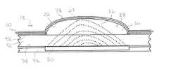
- FIG. 2is a cross sectional view of a capacitive sensor assembly for use in the controller shown in FIG. 1 , as seen along line 2 - 2 in FIG. 1 ;
- FIG. 3is a cross sectional view of the capacitive sensor assembly shown as in FIG. 2 shown after the sensor button has been depressed by a person's finger;
- FIG. 4is an exploded view of the controller shown in FIG. 1 showing the components of a multi-button controller having an LED readout;
- FIG. 5is a cross sectional view of an alternative embodiment of a capacitive sensor assembly for the controller shown in FIG. 1 , as would be seen along line 2 - 2 in FIG. 1 ;
- FIG. 6is a cross sectional view of the capacitive sensor assembly shown as in FIG. 5 , shown after the flexible layer has been depressed by a person's finger to activate the switch;
- FIG. 7is an exploded view of a controller having the capacitive sensor assemblies shown in the FIG. 5 embodiment.
- a controller for use in a wet environmentis shown and generally designated 10 .
- the controllermay be used to control devices associated with a pool, spa, hot tub, boat or industrial equipment that is located in an environment in which water is present.
- the controller 10can include a sealed plastic enclosure 12 , a plurality of sensor buttons 14 and an LED readout 16 .
- the controlleris connected to one or more devices, such as a pumps, a heater and/or lights (not shown), for example, using one or more cables (not shown). Another cable (not shown) can be used to connect the controller 10 to a power supply or outlet (not shown).
- the sensor buttons 14can be depressed by a user to turn a device such as a pump, light or heater. On or Off, or to adjust the speed of a device, for example, pump speed or establish a set point, such as water temperature, using the LED readout 16 .
- FIGS. 2-4illustrate a first embodiment of a capacitive sensor assembly 18 for the controller 10 shown in FIG. 1 .
- the controller 10includes a sensor button 14 having a sensor element 20 and flexible layers 22 , 24 .
- the sensor element 20generates an electric field (field lines 26 illustrated by dashed lines) having an active region 28 .
- the flexible layers 22 , 24are positioned to overlay the sensor element 20 and surround the active region 28 .
- a pocket 30is established between the flexible layer 22 and sensor element 20 .
- This pocket 30can include a compressible medium, such as air, to allow the flexible layers 22 , 24 over the sensor element 20 to be depressed by a user to turn a device not shown) on or off, such as a pump or heater.
- the capacitive sensor element 20can be formed as part of a printed circuit board 32 and can be charged by a power source (not shown) to establish the electric field (field lines 26 ), the strength of which dissipates with distance from the sensor element 20 .
- the capacitive sensor element 20may include an electrode formed in or on the surface 34 of the printed circuit board 32 .
- the electrodecan then be electrically connected via a copper trace (not shown) in the circuit board 32 to an electronic control circuit (not shown) that is configured to output voltages corresponding to a switch state such as an ‘open’ switch state and a ‘closed’ switch state for the capacitive sensor assembly 18 .
- the output voltagesmay then be used to activate/deactivate devices (not shown) such as pumps, heaters, etc.
- the capacitive sensor assembly 18establishes an active region 28 within which the presence of a conductive object such as a finger 36 is sensed and changes the output state of the capacitive sensor assembly 18 .
- the controller 10can include a control circuit (not shown), for example having a processor or other electronic logic elements, that is responsive to the capacitance in the pocket 30 between the sensor element 20 and the flexible layer 22 . Depending on this capacitance, the control circuit generates an output signal that corresponds to a particular switch state for a connected device (not shown), such as a pump or heater.
- the output of the control circuitis a signal having a voltage within a first voltage range for a first switch state and a signal having a voltage within a second voltage range for a second switch state.
- the control circuitis designed and/or calibrated to change a switch state output when the flexible layer 22 is deformed and to maintain a current switch state output, in response to the presence of water or other contaminants on the external surface 38 of layer 24 .
- the flexible layers 22 , 24can be made of a non-conductive material, such as plastic.
- the control circuitwill detect a change in capacitance between the sensor element 20 and ground. Upon sensing the change in capacitance, the control circuit can produce an appropriate output signal that corresponds to a particular switch state for a connected device (not shown).
- FIG. 2further shows that the layer 24 may be bonded via adhesive layer 40 to layer 22 which is in turn bonded via adhesive layer 42 to an external surface of the control enclosure 12 , which is typically made of clear plastic, to surround the active region 28 of the capacitive sensor element 20 .
- the capacitive sensor element 20 and printed circuit board 32may be disposed within the enclosure 12 , as best appreciated by cross referencing FIGS. 1 and 2 . With this arrangement, water droplets from splashing or condensation are unable to inadvertently enter the active region 28 of the capacitive sensor assembly 18 and register a false positive.
- the layers 22 , 24may be shaped to present a concave surface 38 to the user.
- the layer 24may be made of a flexible plastic material such as Lexan which is a trademarked brand of polycarbonate thermoplastic available from SABIC Innovative Plastics' (formerly General Electric Plastics). Labeling may be provided on the flexible plastic material to indicate sensor function as shown in FIG. 1 .
- the layer 22may be made of a clear flexible plastic material such as thermoplastic polyester or some other material having good shape memory to maintain shape after repeated cycling. In some cases, a single layer of material (not shown) may be used in place of the layer 22 , 24 combination.
- the sensor element 20 and control circuitmay be designed and/or calibrated such that objects such as water droplets outside the layer 24 do not inadvertently trigger the capacitive sensor switch assembly 18 .
- FIG. 3shows the sensor switch assembly 18 after the sensor button 14 has been pressed by finger 36 .
- the layers 22 , 24deform to allow the finger 36 to enter the active region 28 ( FIG. 2 ) of the sensor element 20 and change the electric field (as indicated by the electric field lines 26 ′).
- the change in electric fieldis registered by the electronic control circuit, which in turn changes the sensor switch state and corresponding output voltage.
- the assembly 18Upon removal of the finger 36 , the assembly 18 returns to the configuration shown in FIG. 2 .
- the sensor switch assembly 18may be programmed to change states when pressed and hold the changed state when the finger is removed, may be programmed to change states when pressed and revert to the original state when the finger is removed, or may be programmed to change states continuously when pressed and held for a determined length of time until the finger is removed.
- the later configurationmay be used, for example, in conjunction with an LCD readout 16 (or LED readout) or to change a parameter such as temperature to a desired set point.
- FIG. 4shows an exploded view of the controller 10 , shown with optional sensor element extenders 46 .
- the controllerincludes a printed circuit board 32 (PCB) having an LED or LCD readout 16 and a plurality of capacitive sensors element 20 .
- Each extender 46may be electrically connected to a respective capacitive sensor element 20 to extend the active region 28 ( FIG. 2 ) of each capacitive switch assembly 18 ( FIG. 2 ) above the printed PCB surface 34 in instances where the printed circuit board 32 is not or cannot be mounted directly in contact with the face 48 of the enclosure 12 .
- each extender 46may be a steel coil spring.
- the plastic enclosure 12houses, seals and encapsulates the printed circuit board 32 and extenders 46 .
- the enclosure 12may be clear plastic having a thickness in the range of about 1.5 mm to 6.35 mm thick and having a recess 50 on face 48 , as shown, that is about 0.2 mm to 1.5 mm deep.
- layer 22is bonded via adhesive layer 42 to the face 48 of enclosure 12 and within the recess 50
- layer 24is bonded via adhesive layer 40 to layer 22 .
- the layers 22 , 24are formed with conforming concave portions corresponding to each capacitive sensor assembly 18 ( FIG. 2 ).
- the adhesive layers 40 , 42are formed with holes, such as holes 52 a,b corresponding to each capacitive sensor element 20 . Each hole 52 a,b in the adhesive layer 42 between the layer 22 and the face 48 of enclosure 12 together with the volume below the corresponding concave feature in layer 22 establishes a pocket 30 ( FIG. 2 ) containing air or some other compressible medium.
- the adhesive layers 40 , 42 and layer 22can be formed with optional passageways 54 a - c to increase the amount of compressible medium, e.g. air, that is available to compress when the concave shape of the layers 22 , 24 are deformed, making it easier to press the button 14 .
- the adhesive layers 40 , 42may have a thickness in the range of about 0.1 mm to 0.762 mm the layer 22 may have a thickness in the range of about 0.1 mm to 0.3 mm and the layer 24 may have a thickness in the range of about 0.4 mm to 0.6 mm.
- the layer 22 and adhesive layers 40 , 42may be replaced with a single adhesive layer containing holes (not shown).
- buttons 14 in layer 24may be concave, as shown, or may be another shape such as flat. Thus, the layer 24 may be flat (not shown) or embossed with raised portions corresponding to each capacitive sensor element 20 , as shown.
- FIGS. 5 and 6show another embodiment of a capacitive sensor assembly 18 ′ that can be used in the controller 10 shown in FIG. 1 .
- the capacitive sensor assembly 18 ′includes a sensor element 20 ′ and flexible layers 22 ′, 24 ′.
- the sensor element 20 ′generates an electric field (field lines 56 illustrated by dashed lines) having an active region 28 ′.
- the flexible layers 22 ′, 24 ′are positioned to overlay the sensor element 20 ′ and surround the active region 28 ′. With this arrangement, a pocket 30 ′ is established between the flexible layer 22 ′ and sensor element 20 ′.
- This pocket 30 ′can include a compressible medium, such as air, to allow the flexible layers 22 ′, 24 ′ over the sensor element 20 ′ to be depressed by a user to turn a device (not shown) On or Off, such as a pump or heater.
- a compressible mediumsuch as air
- the capacitive sensor element 20 ′can be formed as part of a printed circuit board 32 ′ and can be charged by a power source (not shown) to establish the electric field 56 , the strength of which dissipates with distance from the sensor element 20 ′.
- the capacitive sensor element 20 ′may include an electrode formed in or on the surface 34 ′ of the printed circuit board 32 ′. The electrode can then be electrically connected via a copper trace (not shown) in the circuit board 32 ′ to an electronic control circuit (not shown) that is configured to output voltages corresponding to a switch state such as an ‘open’ switch state and a ‘closed’ switch state for the capacitive sensor assembly 18 ′. The output voltages may then be used to activate/deactivate devices (not shown) such as pumps, heaters, etc.
- layer 22 ′is conductive. Although for clarity purposes the discussion here will describe a conductive layer 22 ′, those skilled in the pertinent art will appreciated that either layer 22 ′ or layer 24 ′ can be conductive, or alternatively, both layers 22 ′, 24 ′ can be conductive.
- the conductive flexible layer 22 ′is capacitively coupled to a ground pad 58 .
- the circuit board 34 ′can include a first circuit board side 60 and an opposed second circuit board side 62 , with the sensor element 20 ′ formed on the first circuit board side 60 and the ground pad 58 overlying, and in some implementations contacting, at least a portion of the second circuit board side 62 .
- a first capacitorwill be established between the sensor element 20 ′ and conductive flexible layer 22 ′ (illustrated by electric field lines 56 ) and a second capacitor will be established between the conductive flexible layer 22 ′ and ground pad 58 (illustrated by electric field lines 64 ).
- the location 66 on the second circuit board side 62 that is diametrically opposite the sensor element 20 ′is not covered by the ground pad 58 .
- each capacitive sensor element 20 ′is in series with the conductive layer 22 ′.
- the conductive layer 22 ′acts as a capacitor by taking on the charge of the fringe of the electric fields 56 of all the capacitive sensor elements 20 ′ in the controller 10 ( FIG. 1 ), thereby shielding them from outside interference and making the conductive layer 22 ′ act as a positive conductive plate in relation to the ground pad 58 on the circuit board 32 ′ and creating the electric field shown by field lines 64 between the layer 22 ′ and ground pad 58 which closes the circuit for each switch.
- buttons 14 ′When the button 14 ′ is pressed as shown in FIG. 6 by pushing its corresponding embossed area (i.e. concave portion) of layers 22 ′, 24 ′ down, and as long as the conductive layer 22 ′ is of a low enough resistance, this action displaces the empty space in pocket 30 ′ ( FIG. 5 ). As this happens, the conductive layer 22 ′ is exposed to more of the electric field (as illustrated by field lines 56 ′ from sensor element 20 in FIG. 6 ), the conductive layer 22 ′ takes an increased charge from the electric field, changing the capacitance between the sensor element 20 ′ and conductive layer 22 ′. This change in capacitance is then registered as a button press. In more mathematical terms, for the construction shown in FIGS.
- the total capacitance (C x )can be calculated by:
- the controller 10can include a control circuit (not shown), for example having a processor or other electronic logic elements, that is responsive to the total capacitance (C x ). Depending on this total capacitance, the control circuit generates an output signal that corresponds to a particular switch state for a connected device (not shown), such as a pump or heater. Typically, the output of the control circuit is a signal having a voltage within a first voltage range for a first switch state and a signal having a voltage within a second voltage range for a second switch state.
- the control circuitis designed and/or calibrated to change a switch state output when the flexible layer 22 ′ is deformed and to maintain a current switch state output in response to the presence of water or other contaminants on the external surface 38 ′ of layer 24 ′.
- FIG. 5further shows that the layer 24 ′ may be bonded via adhesive layer 40 ′ to layer 22 ′ which is in turn bonded via adhesive layer 42 ′ to an external surface of the control enclosure 12 ′, which is typically made of clear plastic, to surround the active region 28 ′ of the capacitive sensor element 20 ′.
- the capacitive sensor element 20 ′ and printed circuit board 32 ′may be disposed within the enclosure 12 ′, as best appreciated by cross referencing FIGS. 1 and 5 . With this arrangement, water droplets from splashing or condensation are unable to inadvertently enter the active region 28 ′ of the capacitive sensor assembly 18 ′ and register a false positive.
- FIGS. 1water droplets from splashing or condensation are unable to inadvertently enter the active region 28 ′ of the capacitive sensor assembly 18 ′ and register a false positive.
- the layers 22 ′, 24 ′may be shaped to present a concave surface 38 ′ to the user. With this concave shape, water droplets may roll off of the layer 24 ′ to prevent water from accumulating to a size sufficient to trigger a false positive.
- the layer 24 ′may be made of a flexible plastic material such as Lexan which is a trademarked brand of polycarbonate thermoplastic available from SABIC Innovative Plastics' (formerly General Electric Plastics). Labeling may be provided on the flexible plastic material to indicate sensor function as shown in FIG. 1 . In some cases, a single layer of conductive material (embodiment not shown) may be used in place of the layer 22 ′, 24 ′ combination.
- the sensor element 20 ′ and control circuitmay be designed and/or calibrated such that objects such as water droplets outside the layer 24 ′ do not inadvertently trigger the capacitive sensor switch assembly 18 ′.
- FIG. 6shows the sensor switch assembly 18 ′ after the sensor button 14 ′ has been pressed by finger 36 ′.
- the layers 22 ′, 24 ′deform to change the capacitance between the sensor element 20 ′ and conductive layer 22 ′ as described above.
- the change in capacitance(or total capacitance C x as described above) can be registered by the electronic control circuit, which in turn changes the sensor switch state and corresponding output voltage.
- the assembly 18 ′Upon removal of the finger 36 ′, the assembly 18 ′ returns to the configuration shown in FIG. 5 .
- FIG. 7shows another embodiment having a conductive layer 22 ′′ (as described above with reference to FIGS. 5 and 6 ) but also including a layer having a plurality of tactile metal domes 68 .
- additional conductive materialcan be added.
- tactile metal domes 68commonly used in membrane switch keypads
- FIG. 7shows that tactile metal domes 68 (commonly used in membrane switch keypads) can be added under the embossed areas of layers 22 ′′, 24 ′′ that are located over the capacitive sensor elements 20 ′′, to lower resistance enough that the sensor element's field can be measurably changed (as long as the added material is in direct contact with the conductive layer 22 ′′).
- An exemplary embodiment of the controller 10 ′′ shown in FIG. 7typically includes a multilayer circuit hoard 32 ′′ with capacitive sensor elements 20 ′′, other electronic components and a processor on the top circuit board layer, and a bottom layer comprised of a ground pad (such as ground pad 58 shown in FIG. 5 ) which covers all or most of the area of the bottom layer of the circuit board 32 ′′.
- This circuit board 32 ′′is typically mounted inside a sealed enclosure 12 ′′ (made of clear plastic) to protect it from the harsh/wet environment.
- An external multi-layer graphic overlay(comprised of a plastic layer 24 ′′, conductive layer 22 ′′, and adhesive layers 40 ′′, 42 ′′) is affixed to the outside of the enclosure 12 ′′, over the area the circuit board 32 ′′.
- FIG. 7shows an exploded view of an embodiment of a controller 10 ′′ having a printed circuit board 32 ′′ (PCB) having an LED or LCD readout 16 ′′, a plurality of capacitive sensor elements 20 ′′, each electrically connected a respective extender 46 ′′ to extend the active region 28 ′′ ( FIG. 5 ) of each capacitive switch assembly 18 ′ ( FIG. 5 ) above the printed PCB surface 34 ′′ in instances where the printed circuit board 32 ′′ is not or cannot be mounted directly in contact with the face 48 ′′ of the enclosure 12 ′′.
- each extender 46 ′′may be a steel coil spring.
- the plastic enclosure 12 ′′houses, seals and encapsulates the printed circuit board 32 ′′ and extenders 46 ′′.
- the enclosure 12 ′′may be clear plastic having a thickness in the range of about 1.5 mm to 6.35 mm thick and having a recess 50 ′′ on face 48 ′′, as shown, that is about 0.2 mm to 1.5 mm deep.
- a plastic bottom layer 70is bonded via adhesive layer 72 to the face 48 ′′ of enclosure 12 ′′ and within the recess 50 ′′.
- Layer 74 having tactile metal domes 68is bonded via adhesive layer 76 to layer 70 , as shown.
- the layers 22 ′′, 24 ′′are formed with conforming concave portions corresponding to each capacitive sensor assembly 18 ′ ( FIG. 5 ).
- conductive layer 22 ′′is bonded via adhesive layer 42 ′′ to layer 74 and layer 24 ′′ is bonded via adhesive layer 40 ′′ to layer 22 ′′.
- the adhesive layers 40 ′′, 42 ′′, 76are formed with holes, such as holes 52 a′′,b′′,c ′′ corresponding to each capacitive sensor element 20 ′′. Holes 52 b′′,c′′ in the adhesive layers 40 ′′, 42 ′′ allow for contact between the domes 68 , layer 22 ′′ and layer 24 ′′ over a respective sensor element 20 ′′. Hole 62 a ′′ in the adhesive layer 76 together with the volume under dome 68 establishes a pocket (similar to pocket 30 ′ shown in FIG. 5 ) containing air or some other compressible medium.
- the layers 40 ′′, 22 ′′, 42 ′′, 74 and 76can be formed with optional passageways 54 a ′′- 54 e ′′ to increase the amount of compressible medium, e.g. air, that is available to compress when the concave shape of the layers 22 ′′, 24 ′′ are deformed, making it easier to press the button 14 ′′.
- the adhesive layers 40 ′′, 42 ′′, 76may have a thickness in the range of about 0.1 mm to 0.762 mm and the layer 22 ′′ may have a thickness in the range of about 0.1 mm to 0.3 mm and the layer 24 ′′ may have a thickness in the range of about 0.4 mm to 0.6 mm.
- the layer 22 ′′ and adhesive layers 40 ′′, 42 ′′may be replaced with a single adhesive layer containing holes (not shown).
- the optional passageways 54 a ′′- 54 e ′′may extend, as shown, to adjacent holes, to provide a greater pocket volume for each button 14 ′′. This extra volume acts to decrease the system's resistance to button pressing (i.e. to make the buttons easier to press).
- Buttons 14 ′′ in layer 24 ′′may be concave, as shown, or may be another shape such as flat.
- the layer 24 ′′may be flat (not shown) or embossed with raised portions corresponding to each capacitive sensor element 20 ′′, as shown.
Landscapes
- Engineering & Computer Science (AREA)
- General Engineering & Computer Science (AREA)
- Theoretical Computer Science (AREA)
- Switches That Are Operated By Magnetic Or Electric Fields (AREA)
- Human Computer Interaction (AREA)
- Physics & Mathematics (AREA)
- General Physics & Mathematics (AREA)
- Push-Button Switches (AREA)
Abstract
Description
Claims (7)
Priority Applications (2)
| Application Number | Priority Date | Filing Date | Title |
|---|---|---|---|
| US13/671,412US9063623B2 (en) | 2011-12-01 | 2012-11-07 | Capacitive touch sensor assembly for use in a wet environment |
| CN201310547847.7ACN103809825A (en) | 2011-12-01 | 2013-11-07 | Capacitive touch sensor assembly for use in a wet environment |
Applications Claiming Priority (2)
| Application Number | Priority Date | Filing Date | Title |
|---|---|---|---|
| US201161565945P | 2011-12-01 | 2011-12-01 | |
| US13/671,412US9063623B2 (en) | 2011-12-01 | 2012-11-07 | Capacitive touch sensor assembly for use in a wet environment |
Publications (2)
| Publication Number | Publication Date |
|---|---|
| US20130141387A1 US20130141387A1 (en) | 2013-06-06 |
| US9063623B2true US9063623B2 (en) | 2015-06-23 |
Family
ID=48523635
Family Applications (1)
| Application Number | Title | Priority Date | Filing Date |
|---|---|---|---|
| US13/671,412Active2033-06-20US9063623B2 (en) | 2011-12-01 | 2012-11-07 | Capacitive touch sensor assembly for use in a wet environment |
Country Status (2)
| Country | Link |
|---|---|
| US (1) | US9063623B2 (en) |
| CN (1) | CN103809825A (en) |
Cited By (2)
| Publication number | Priority date | Publication date | Assignee | Title |
|---|---|---|---|---|
| US20150033466A1 (en)* | 2011-04-26 | 2015-02-05 | C.G. Air Systèmes Inc. | Resistive actuation unit for tub systems |
| US10116306B2 (en)* | 2016-09-19 | 2018-10-30 | Apple Inc. | Touch and force sensitive rocker switch |
Families Citing this family (14)
| Publication number | Priority date | Publication date | Assignee | Title |
|---|---|---|---|---|
| DE102013010263A1 (en)* | 2013-06-18 | 2014-12-18 | Diehl Ako Stiftung & Co. Kg | Capacitive touch switch |
| US9836637B2 (en)* | 2014-01-15 | 2017-12-05 | Google Llc | Finger print state integration with non-application processor functions for power savings in an electronic device |
| KR102229006B1 (en)* | 2014-01-16 | 2021-03-17 | 삼성전자주식회사 | Method and apparatus for processing input using touch screen |
| JP6553653B2 (en) | 2014-06-27 | 2019-07-31 | コーニンクレッカ フィリップス エヌ ヴェKoninklijke Philips N.V. | Household appliances with output control |
| JP6613657B2 (en)* | 2015-06-29 | 2019-12-04 | ぺんてる株式会社 | Capacitive coupling type electrostatic sensor |
| US10660819B2 (en) | 2015-07-16 | 2020-05-26 | Bestway Inflatables & Material Corp. | Pool pump |
| CN105094234A (en)* | 2015-08-21 | 2015-11-25 | 广东欧珀移动通信有限公司 | Terminal |
| TWI585664B (en)* | 2016-04-01 | 2017-06-01 | 意象無限股份有限公司 | Touch panel identification method |
| TWI604356B (en)* | 2016-09-09 | 2017-11-01 | 意象無限股份有限公司 | Touch system and touch detection method of the same |
| DE102016217545A1 (en)* | 2016-09-14 | 2018-03-15 | Mayser Gmbh & Co. Kg | Non-contact capacitive sensor, method for detecting the approach of a human or animal body part and arrangement with a sensor |
| CN206164498U (en)* | 2016-10-14 | 2017-05-10 | 广州视源电子科技股份有限公司 | Touch key device and touch equipment |
| CN107179150A (en)* | 2017-05-23 | 2017-09-19 | 福州大学 | A kind of fan-like pattern robot touch sensor and its detection method |
| JP2019032916A (en)* | 2017-08-08 | 2019-02-28 | 日本電産サンキョー株式会社 | Card reader and its foreign material detection method |
| IT201800003390A1 (en)* | 2018-03-09 | 2019-09-09 | Dab Pumps Spa | ASSEMBLED OF CENTRIFUGAL ELECTRIC PUMP WITH PERFECT SEAL |
Citations (45)
| Publication number | Priority date | Publication date | Assignee | Title |
|---|---|---|---|---|
| US4046975A (en)* | 1975-09-22 | 1977-09-06 | Chomerics, Inc. | Keyboard switch assembly having internal gas passages preformed in spacer member |
| US4304976A (en) | 1978-03-16 | 1981-12-08 | Texas Instruments Incorporated | Capacitive touch switch panel |
| US4377049A (en) | 1980-05-22 | 1983-03-22 | Pepsico Inc. | Capacitive switching panel |
| US4413252A (en) | 1980-01-23 | 1983-11-01 | Robertshaw Controls Company | Capacitive switch and panel |
| US4561002A (en) | 1982-08-30 | 1985-12-24 | General Electric Company | Capacitive touch switch arrangement |
| US4875497A (en) | 1984-04-23 | 1989-10-24 | Worthington Ralph T | Capacitance liquid level sensing and touch control system |
| US5012124A (en) | 1989-07-24 | 1991-04-30 | Hollaway Jerrell P | Touch sensitive control panel |
| USD363060S (en) | 1994-10-31 | 1995-10-10 | Jacuzzi, Inc. | Planar touch pad control panel for spas |
| US5883459A (en) | 1997-07-21 | 1999-03-16 | Balboa Instruments Inc. | Electrical switch assembly encapsulated against moisture intrusion |
| US5917165A (en)* | 1997-02-17 | 1999-06-29 | E.G.O. Elektro-Geraetebau Gmbh | Touch switch with flexible, intermediate conductive spacer as sensor button |
| US6016020A (en) | 1997-09-03 | 2000-01-18 | Balboa Instruments, Inc. | Method and apparatus using low voltage level actuator to control operation of electrical appliance |
| US6373265B1 (en) | 1999-02-02 | 2002-04-16 | Nitta Corporation | Electrostatic capacitive touch sensor |
| US6667563B2 (en) | 2000-06-01 | 2003-12-23 | Lg Electronics Inc | Touch switching apparatus |
| US20050045621A1 (en) | 2003-09-02 | 2005-03-03 | Francois Chenier | Bathing unit control system with capacitive water level sensor |
| US20050076302A1 (en) | 2003-10-03 | 2005-04-07 | Canon Kabushiki Kaisha | Display apparatus |
| US7084933B2 (en) | 2002-11-14 | 2006-08-01 | Lg.Philips Lcd Co., Ltd. | Touch panel for display device |
| US20060243575A1 (en) | 2005-04-25 | 2006-11-02 | Electrolux Home Products Corporation N.V. | Control panel with illuminated capacitive touch-control switches |
| US20070101489A1 (en) | 2004-11-08 | 2007-05-10 | Dimension One Spas | Spa Capacitive Switch |
| US7232973B2 (en) | 2004-12-17 | 2007-06-19 | Diehl Ako Stiftung & Co. Kg | Capacitive touch switch |
| US20080231605A1 (en) | 2007-03-21 | 2008-09-25 | Kai-Ti Yang | Compound touch panel |
| US20080273016A1 (en) | 2007-05-04 | 2008-11-06 | Electrolux Home Products, Inc. | Integrated touch-screen control panel for a washing appliance and method for producing the same |
| US20090027356A1 (en) | 2007-07-26 | 2009-01-29 | Diehl Ako Stiftung & Co. Kg | Capacitive Touch Switch |
| US20090058818A1 (en) | 2007-08-29 | 2009-03-05 | Egalax_Empia Technology Inc. | Device and method for determining touch position on sensing area of capacitive touch panel |
| US7511242B2 (en) | 2007-02-12 | 2009-03-31 | E.G.O. Elektro-Geraetebau Gmbh | Sensor element for a touch switch, method for the manufacture of a sensor element and touch switch |
| US20090085892A1 (en) | 2006-03-01 | 2009-04-02 | Kenichiro Ishikura | Input device using touch panel |
| US7525062B2 (en) | 2002-10-29 | 2009-04-28 | Bsh Bosch Und Siemens Hausgeraete Gmbh | Capacitive proximity and/or contact sensor and electrically conductive plastic body for such a sensor |
| US20090125736A1 (en) | 2007-09-21 | 2009-05-14 | Lg Electronics Inc. | Home appliance and controlling method of the same |
| US20090135157A1 (en) | 2007-11-27 | 2009-05-28 | Avago Technologies Ecbu Ip (Singapore) Pte. Ltd. | Capacitive Sensing Input Device with Reduced Sensitivity to Humidity and Condensation |
| US20090153502A1 (en) | 2007-12-14 | 2009-06-18 | Tsinghua University | Touch panel and display device using the same |
| US7579569B2 (en) | 2004-09-29 | 2009-08-25 | Bsh Bosch Und Siemens Hausgeraete Gmbh | Capacitive proximity and/or touch-sensitive switch |
| US20090278714A1 (en) | 2008-05-12 | 2009-11-12 | Holtek Semiconductor Inc. | Capacitive button device |
| US7652220B2 (en) | 2005-08-19 | 2010-01-26 | E.G.O. Elektro-Geraetebau Gmbh | Sensor device |
| US20100078304A1 (en) | 2008-09-26 | 2010-04-01 | Diehl Ako Stiftung & Co. Kg | Operator Control Panel for a Domestic Appliance |
| US20100102830A1 (en) | 2008-10-27 | 2010-04-29 | Microchip Technology Incorporated | Physical Force Capacitive Touch Sensor |
| US20100147602A1 (en) | 2008-11-05 | 2010-06-17 | Lg Electronics Inc. | Home appliance and washing machine |
| US7741858B2 (en) | 2006-06-09 | 2010-06-22 | Lg Electronics Inc. | Capacitive switch of electric/electronic device |
| US20100181181A1 (en) | 2009-01-22 | 2010-07-22 | E.G.O. Elektro-Geraetebau Gmbh | Operating device for an electrical appliance |
| US7821274B2 (en) | 2007-05-07 | 2010-10-26 | Atmel Corporation | Capacitive position sensor |
| US20100276268A1 (en) | 2007-09-18 | 2010-11-04 | BSH Bosch und Siemens Hausgeräte GmbH | Capacitive proximity and/or touch switch |
| US7834287B2 (en) | 2005-11-09 | 2010-11-16 | Diehl Ako Stiftung & Co. Kg | Capacitive touch switch |
| US20100294641A1 (en) | 2005-06-21 | 2010-11-25 | Horst Kunkel | Sanitary Fitting With an Electrical Operating Device, Which has at Least One Capacitive Sensor |
| US20110004994A1 (en) | 2009-07-13 | 2011-01-13 | Luraco Technologies, Inc. | Apparatus, system and method for multi-function intelligent spa control |
| US20110032193A1 (en) | 2009-08-07 | 2011-02-10 | Openpeak, Inc. | Projected capacitive touch-sensitive panel |
| US20110090173A1 (en) | 2009-10-19 | 2011-04-21 | Orise Technology Co., Ltd. | Sensing circuit for use with capacitive touch panel |
| US20110109590A1 (en) | 2008-06-27 | 2011-05-12 | Jae Bum Park | Window panel integrated capacitive-type touch sensor and a fabrication method therefor |
Family Cites Families (5)
| Publication number | Priority date | Publication date | Assignee | Title |
|---|---|---|---|---|
| JP4245512B2 (en)* | 2004-05-24 | 2009-03-25 | アルプス電気株式会社 | Input device |
| JP2010244772A (en)* | 2009-04-03 | 2010-10-28 | Sony Corp | Capacitance type touch member and method for producing the same, and capacitance type touch detection device |
| EP2270634A1 (en)* | 2009-06-30 | 2011-01-05 | Roland Oliver Lamb | Force-sensitive processor interface |
| WO2011003113A1 (en)* | 2009-07-03 | 2011-01-06 | Tactus Technology | User interface enhancement system |
| CN102375586B (en)* | 2010-08-19 | 2014-12-03 | 苏州敏芯微电子技术有限公司 | Control system for identifying direction and force |
- 2012
- 2012-11-07USUS13/671,412patent/US9063623B2/enactiveActive
- 2013
- 2013-11-07CNCN201310547847.7Apatent/CN103809825A/enactivePending
Patent Citations (45)
| Publication number | Priority date | Publication date | Assignee | Title |
|---|---|---|---|---|
| US4046975A (en)* | 1975-09-22 | 1977-09-06 | Chomerics, Inc. | Keyboard switch assembly having internal gas passages preformed in spacer member |
| US4304976A (en) | 1978-03-16 | 1981-12-08 | Texas Instruments Incorporated | Capacitive touch switch panel |
| US4413252A (en) | 1980-01-23 | 1983-11-01 | Robertshaw Controls Company | Capacitive switch and panel |
| US4377049A (en) | 1980-05-22 | 1983-03-22 | Pepsico Inc. | Capacitive switching panel |
| US4561002A (en) | 1982-08-30 | 1985-12-24 | General Electric Company | Capacitive touch switch arrangement |
| US4875497A (en) | 1984-04-23 | 1989-10-24 | Worthington Ralph T | Capacitance liquid level sensing and touch control system |
| US5012124A (en) | 1989-07-24 | 1991-04-30 | Hollaway Jerrell P | Touch sensitive control panel |
| USD363060S (en) | 1994-10-31 | 1995-10-10 | Jacuzzi, Inc. | Planar touch pad control panel for spas |
| US5917165A (en)* | 1997-02-17 | 1999-06-29 | E.G.O. Elektro-Geraetebau Gmbh | Touch switch with flexible, intermediate conductive spacer as sensor button |
| US5883459A (en) | 1997-07-21 | 1999-03-16 | Balboa Instruments Inc. | Electrical switch assembly encapsulated against moisture intrusion |
| US6016020A (en) | 1997-09-03 | 2000-01-18 | Balboa Instruments, Inc. | Method and apparatus using low voltage level actuator to control operation of electrical appliance |
| US6373265B1 (en) | 1999-02-02 | 2002-04-16 | Nitta Corporation | Electrostatic capacitive touch sensor |
| US6667563B2 (en) | 2000-06-01 | 2003-12-23 | Lg Electronics Inc | Touch switching apparatus |
| US7525062B2 (en) | 2002-10-29 | 2009-04-28 | Bsh Bosch Und Siemens Hausgeraete Gmbh | Capacitive proximity and/or contact sensor and electrically conductive plastic body for such a sensor |
| US7084933B2 (en) | 2002-11-14 | 2006-08-01 | Lg.Philips Lcd Co., Ltd. | Touch panel for display device |
| US20050045621A1 (en) | 2003-09-02 | 2005-03-03 | Francois Chenier | Bathing unit control system with capacitive water level sensor |
| US20050076302A1 (en) | 2003-10-03 | 2005-04-07 | Canon Kabushiki Kaisha | Display apparatus |
| US7579569B2 (en) | 2004-09-29 | 2009-08-25 | Bsh Bosch Und Siemens Hausgeraete Gmbh | Capacitive proximity and/or touch-sensitive switch |
| US20070101489A1 (en) | 2004-11-08 | 2007-05-10 | Dimension One Spas | Spa Capacitive Switch |
| US7232973B2 (en) | 2004-12-17 | 2007-06-19 | Diehl Ako Stiftung & Co. Kg | Capacitive touch switch |
| US20060243575A1 (en) | 2005-04-25 | 2006-11-02 | Electrolux Home Products Corporation N.V. | Control panel with illuminated capacitive touch-control switches |
| US20100294641A1 (en) | 2005-06-21 | 2010-11-25 | Horst Kunkel | Sanitary Fitting With an Electrical Operating Device, Which has at Least One Capacitive Sensor |
| US7652220B2 (en) | 2005-08-19 | 2010-01-26 | E.G.O. Elektro-Geraetebau Gmbh | Sensor device |
| US7834287B2 (en) | 2005-11-09 | 2010-11-16 | Diehl Ako Stiftung & Co. Kg | Capacitive touch switch |
| US20090085892A1 (en) | 2006-03-01 | 2009-04-02 | Kenichiro Ishikura | Input device using touch panel |
| US7741858B2 (en) | 2006-06-09 | 2010-06-22 | Lg Electronics Inc. | Capacitive switch of electric/electronic device |
| US7511242B2 (en) | 2007-02-12 | 2009-03-31 | E.G.O. Elektro-Geraetebau Gmbh | Sensor element for a touch switch, method for the manufacture of a sensor element and touch switch |
| US20080231605A1 (en) | 2007-03-21 | 2008-09-25 | Kai-Ti Yang | Compound touch panel |
| US20080273016A1 (en) | 2007-05-04 | 2008-11-06 | Electrolux Home Products, Inc. | Integrated touch-screen control panel for a washing appliance and method for producing the same |
| US7821274B2 (en) | 2007-05-07 | 2010-10-26 | Atmel Corporation | Capacitive position sensor |
| US20090027356A1 (en) | 2007-07-26 | 2009-01-29 | Diehl Ako Stiftung & Co. Kg | Capacitive Touch Switch |
| US20090058818A1 (en) | 2007-08-29 | 2009-03-05 | Egalax_Empia Technology Inc. | Device and method for determining touch position on sensing area of capacitive touch panel |
| US20100276268A1 (en) | 2007-09-18 | 2010-11-04 | BSH Bosch und Siemens Hausgeräte GmbH | Capacitive proximity and/or touch switch |
| US20090125736A1 (en) | 2007-09-21 | 2009-05-14 | Lg Electronics Inc. | Home appliance and controlling method of the same |
| US20090135157A1 (en) | 2007-11-27 | 2009-05-28 | Avago Technologies Ecbu Ip (Singapore) Pte. Ltd. | Capacitive Sensing Input Device with Reduced Sensitivity to Humidity and Condensation |
| US20090153502A1 (en) | 2007-12-14 | 2009-06-18 | Tsinghua University | Touch panel and display device using the same |
| US20090278714A1 (en) | 2008-05-12 | 2009-11-12 | Holtek Semiconductor Inc. | Capacitive button device |
| US20110109590A1 (en) | 2008-06-27 | 2011-05-12 | Jae Bum Park | Window panel integrated capacitive-type touch sensor and a fabrication method therefor |
| US20100078304A1 (en) | 2008-09-26 | 2010-04-01 | Diehl Ako Stiftung & Co. Kg | Operator Control Panel for a Domestic Appliance |
| US20100102830A1 (en) | 2008-10-27 | 2010-04-29 | Microchip Technology Incorporated | Physical Force Capacitive Touch Sensor |
| US20100147602A1 (en) | 2008-11-05 | 2010-06-17 | Lg Electronics Inc. | Home appliance and washing machine |
| US20100181181A1 (en) | 2009-01-22 | 2010-07-22 | E.G.O. Elektro-Geraetebau Gmbh | Operating device for an electrical appliance |
| US20110004994A1 (en) | 2009-07-13 | 2011-01-13 | Luraco Technologies, Inc. | Apparatus, system and method for multi-function intelligent spa control |
| US20110032193A1 (en) | 2009-08-07 | 2011-02-10 | Openpeak, Inc. | Projected capacitive touch-sensitive panel |
| US20110090173A1 (en) | 2009-10-19 | 2011-04-21 | Orise Technology Co., Ltd. | Sensing circuit for use with capacitive touch panel |
Cited By (5)
| Publication number | Priority date | Publication date | Assignee | Title |
|---|---|---|---|---|
| US20150033466A1 (en)* | 2011-04-26 | 2015-02-05 | C.G. Air Systèmes Inc. | Resistive actuation unit for tub systems |
| US9610216B2 (en)* | 2011-04-26 | 2017-04-04 | C.G. Air Systèmes Inc. | Resistive actuation unit for tub systems |
| US10116306B2 (en)* | 2016-09-19 | 2018-10-30 | Apple Inc. | Touch and force sensitive rocker switch |
| US10734997B2 (en) | 2016-09-19 | 2020-08-04 | Apple Inc. | Touch and force sensitive rocker switch |
| US11121709B2 (en) | 2016-09-19 | 2021-09-14 | Apple Inc. | Electronic watch with side input button |
Also Published As
| Publication number | Publication date |
|---|---|
| CN103809825A (en) | 2014-05-21 |
| US20130141387A1 (en) | 2013-06-06 |
Similar Documents
| Publication | Publication Date | Title |
|---|---|---|
| US9063623B2 (en) | Capacitive touch sensor assembly for use in a wet environment | |
| CN114741007B (en) | Input device with force sensor | |
| EP2846465B1 (en) | Pressure dependent capacitive sensing circuit switch construction | |
| US20130093681A1 (en) | Capacitive touch key panel | |
| US20060232559A1 (en) | Capacitive touchpad with physical key function | |
| EP2053490A1 (en) | Input panel and portable electronic device using the same | |
| CN102012772A (en) | Capacitive control panel | |
| US20180039351A1 (en) | Methods and apparatus for metal touch sensor | |
| CN104995840A (en) | Physical force capacitive touch sensors | |
| ATE438225T1 (en) | CAPACITIVE TOUCH SWITCH | |
| US20070018965A1 (en) | Illuminated touch control interface | |
| KR102236099B1 (en) | Touch sensing device and electronic device capable of identifying positions of multi-touch | |
| US20110232976A1 (en) | Capacitive touch pad with adjacent touch pad electric field suppression | |
| US9257243B2 (en) | Operating device, in particular for a vehicle component | |
| US8493357B2 (en) | Mechanical means for providing haptic feedback in connection with capacitive sensing mechanisms | |
| EP4252564A1 (en) | Battery rod for electronic atomization and electronic atomization device | |
| KR20150101859A (en) | Waterproof pack case for personal portable device having capacitance type touch panel | |
| CN101425418B (en) | Input panel and portable electronic device using same | |
| CN111917405A (en) | Force sensitive capacitance sensor | |
| JP6392504B2 (en) | Control panel | |
| KR100895147B1 (en) | Refrigerator | |
| EP3365760A1 (en) | Device with mechanical keys and capacitance measurement | |
| TW202013409A (en) | Touch sensor and wiring device | |
| KR102369438B1 (en) | Case for electronic device | |
| KR102134805B1 (en) | Force sensor switch with click feeling |
Legal Events
| Date | Code | Title | Description |
|---|---|---|---|
| AS | Assignment | Owner name:UNITED SPAS, INC., CALIFORNIA Free format text:ASSIGNMENT OF ASSIGNORS INTEREST;ASSIGNOR:ROYHOB, SAM;REEL/FRAME:029347/0363 Effective date:20121113 | |
| AS | Assignment | Owner name:GREEN CEDAR HOLDINGS LLC, CALIFORNIA Free format text:ASSIGNMENT OF ASSIGNORS INTEREST;ASSIGNOR:UNITED SPAS, INC.;REEL/FRAME:035632/0538 Effective date:20150513 | |
| STCF | Information on status: patent grant | Free format text:PATENTED CASE | |
| AS | Assignment | Owner name:UNITED SPAS, INC., CALIFORNIA Free format text:ASSIGNMENT OF ASSIGNORS INTEREST;ASSIGNOR:GREEN CEDAR HOLDINGS, LLC;REEL/FRAME:038686/0809 Effective date:20160511 | |
| MAFP | Maintenance fee payment | Free format text:PAYMENT OF MAINTENANCE FEE, 4TH YR, SMALL ENTITY (ORIGINAL EVENT CODE: M2551); ENTITY STATUS OF PATENT OWNER: SMALL ENTITY Year of fee payment:4 | |
| AS | Assignment | Owner name:MEZE-TECH CORPORATION, CALIFORNIA Free format text:ASSIGNMENT OF ASSIGNORS INTEREST;ASSIGNOR:UNITED SPAS, INC.;REEL/FRAME:049793/0946 Effective date:20190718 | |
| FEPP | Fee payment procedure | Free format text:MAINTENANCE FEE REMINDER MAILED (ORIGINAL EVENT CODE: REM.); ENTITY STATUS OF PATENT OWNER: SMALL ENTITY | |
| FEPP | Fee payment procedure | Free format text:7.5 YR SURCHARGE - LATE PMT W/IN 6 MO, SMALL ENTITY (ORIGINAL EVENT CODE: M2555); ENTITY STATUS OF PATENT OWNER: SMALL ENTITY | |
| MAFP | Maintenance fee payment | Free format text:PAYMENT OF MAINTENANCE FEE, 8TH YR, SMALL ENTITY (ORIGINAL EVENT CODE: M2552); ENTITY STATUS OF PATENT OWNER: SMALL ENTITY Year of fee payment:8 |