US9063549B1 - Light detection and ranging device with oscillating mirror driven by magnetically interactive coil - Google Patents
Light detection and ranging device with oscillating mirror driven by magnetically interactive coilDownload PDFInfo
- Publication number
- US9063549B1 US9063549B1US13/787,107US201313787107AUS9063549B1US 9063549 B1US9063549 B1US 9063549B1US 201313787107 AUS201313787107 AUS 201313787107AUS 9063549 B1US9063549 B1US 9063549B1
- Authority
- US
- United States
- Prior art keywords
- mirror
- conductive coil
- rotation
- axis
- light
- Prior art date
- Legal status (The legal status is an assumption and is not a legal conclusion. Google has not performed a legal analysis and makes no representation as to the accuracy of the status listed.)
- Active, expires
Links
- 238000001514detection methodMethods0.000titleclaimsabstractdescription14
- 230000002452interceptive effectEffects0.000title1
- 230000005291magnetic effectEffects0.000claimsabstractdescription76
- 238000000034methodMethods0.000claimsdescription30
- 230000033001locomotionEffects0.000claimsdescription20
- 230000003534oscillatory effectEffects0.000claimsdescription20
- 230000008859changeEffects0.000claimsdescription15
- 230000003287optical effectEffects0.000claimsdescription12
- 230000010355oscillationEffects0.000claimsdescription9
- 230000004044responseEffects0.000claimsdescription8
- 230000005294ferromagnetic effectEffects0.000claimsdescription4
- 230000003993interactionEffects0.000claimsdescription4
- 230000000737periodic effectEffects0.000claims2
- 239000000758substrateSubstances0.000description58
- 238000004891communicationMethods0.000description31
- 238000010586diagramMethods0.000description14
- 230000006870functionEffects0.000description14
- 238000006073displacement reactionMethods0.000description12
- 238000013500data storageMethods0.000description10
- 230000002093peripheral effectEffects0.000description10
- 230000008569processEffects0.000description10
- 230000000694effectsEffects0.000description9
- 239000000463materialSubstances0.000description9
- 230000004927fusionEffects0.000description7
- 230000005540biological transmissionEffects0.000description6
- 230000001133accelerationEffects0.000description5
- 238000004590computer programMethods0.000description5
- 230000007613environmental effectEffects0.000description5
- 239000004020conductorSubstances0.000description4
- 238000004804windingMethods0.000description4
- 229910052782aluminiumInorganic materials0.000description3
- XAGFODPZIPBFFR-UHFFFAOYSA-NaluminiumChemical compound[Al]XAGFODPZIPBFFR-UHFFFAOYSA-N0.000description3
- 239000011248coating agentSubstances0.000description3
- 238000000576coating methodMethods0.000description3
- 238000011156evaluationMethods0.000description3
- 239000000446fuelSubstances0.000description3
- 239000011521glassSubstances0.000description3
- 238000005259measurementMethods0.000description3
- 238000003860storageMethods0.000description3
- LFQSCWFLJHTTHZ-UHFFFAOYSA-NEthanolChemical compoundCCOLFQSCWFLJHTTHZ-UHFFFAOYSA-N0.000description2
- XEEYBQQBJWHFJM-UHFFFAOYSA-NIronChemical compound[Fe]XEEYBQQBJWHFJM-UHFFFAOYSA-N0.000description2
- PXHVJJICTQNCMI-UHFFFAOYSA-NNickelChemical compound[Ni]PXHVJJICTQNCMI-UHFFFAOYSA-N0.000description2
- ATUOYWHBWRKTHZ-UHFFFAOYSA-NPropaneChemical compoundCCCATUOYWHBWRKTHZ-UHFFFAOYSA-N0.000description2
- 239000000853adhesiveSubstances0.000description2
- 230000001070adhesive effectEffects0.000description2
- 230000008901benefitEffects0.000description2
- 230000010267cellular communicationEffects0.000description2
- 238000010276constructionMethods0.000description2
- 230000001934delayEffects0.000description2
- 239000003302ferromagnetic materialSubstances0.000description2
- PCHJSUWPFVWCPO-UHFFFAOYSA-NgoldChemical compound[Au]PCHJSUWPFVWCPO-UHFFFAOYSA-N0.000description2
- 229910052737goldInorganic materials0.000description2
- 239000010931goldSubstances0.000description2
- 238000010438heat treatmentMethods0.000description2
- 229910052761rare earth metalInorganic materials0.000description2
- 150000002910rare earth metalsChemical class0.000description2
- 230000001172regenerating effectEffects0.000description2
- 230000004043responsivenessEffects0.000description2
- 230000035945sensitivityEffects0.000description2
- 238000000926separation methodMethods0.000description2
- 101100175317Danio rerio gdf6a geneProteins0.000description1
- HBBGRARXTFLTSG-UHFFFAOYSA-NLithium ionChemical compound[Li+]HBBGRARXTFLTSG-UHFFFAOYSA-N0.000description1
- 241001061076Melanonus zugmayeriSpecies0.000description1
- BQCADISMDOOEFD-UHFFFAOYSA-NSilverChemical compound[Ag]BQCADISMDOOEFD-UHFFFAOYSA-N0.000description1
- ATJFFYVFTNAWJD-UHFFFAOYSA-NTinChemical compound[Sn]ATJFFYVFTNAWJD-UHFFFAOYSA-N0.000description1
- 239000002253acidSubstances0.000description1
- 230000009471actionEffects0.000description1
- 239000000654additiveSubstances0.000description1
- 230000000996additive effectEffects0.000description1
- 238000004458analytical methodMethods0.000description1
- 238000004873anchoringMethods0.000description1
- 238000013459approachMethods0.000description1
- 238000003491arrayMethods0.000description1
- 230000004888barrier functionEffects0.000description1
- 239000003990capacitorSubstances0.000description1
- 230000001427coherent effectEffects0.000description1
- 230000001276controlling effectEffects0.000description1
- 238000007599dischargingMethods0.000description1
- 238000009826distributionMethods0.000description1
- 239000000835fiberSubstances0.000description1
- 230000005057finger movementEffects0.000description1
- 230000004907fluxEffects0.000description1
- 230000008571general functionEffects0.000description1
- 229910052742ironInorganic materials0.000description1
- 229910001416lithium ionInorganic materials0.000description1
- 238000004519manufacturing processMethods0.000description1
- 230000007246mechanismEffects0.000description1
- 229910052751metalInorganic materials0.000description1
- 239000002184metalSubstances0.000description1
- 239000010705motor oilSubstances0.000description1
- 229910001172neodymium magnetInorganic materials0.000description1
- 229910052759nickelInorganic materials0.000description1
- 230000003647oxidationEffects0.000description1
- 238000007254oxidation reactionMethods0.000description1
- 239000003208petroleumSubstances0.000description1
- 238000005498polishingMethods0.000description1
- 239000001294propaneSubstances0.000description1
- 230000005855radiationEffects0.000description1
- 230000001105regulatory effectEffects0.000description1
- 229910052709silverInorganic materials0.000description1
- 239000004332silverSubstances0.000description1
- 238000001228spectrumMethods0.000description1
- 239000000126substanceSubstances0.000description1
- 238000010897surface acoustic wave methodMethods0.000description1
- 229910052718tinInorganic materials0.000description1
- 238000002211ultraviolet spectrumMethods0.000description1
Images


Classifications
- G—PHYSICS
- G05—CONTROLLING; REGULATING
- G05D—SYSTEMS FOR CONTROLLING OR REGULATING NON-ELECTRIC VARIABLES
- G05D1/00—Control of position, course, altitude or attitude of land, water, air or space vehicles, e.g. using automatic pilots
- G05D1/02—Control of position or course in two dimensions
- G05D1/021—Control of position or course in two dimensions specially adapted to land vehicles
- G05D1/0231—Control of position or course in two dimensions specially adapted to land vehicles using optical position detecting means
- G—PHYSICS
- G01—MEASURING; TESTING
- G01S—RADIO DIRECTION-FINDING; RADIO NAVIGATION; DETERMINING DISTANCE OR VELOCITY BY USE OF RADIO WAVES; LOCATING OR PRESENCE-DETECTING BY USE OF THE REFLECTION OR RERADIATION OF RADIO WAVES; ANALOGOUS ARRANGEMENTS USING OTHER WAVES
- G01S13/00—Systems using the reflection or reradiation of radio waves, e.g. radar systems; Analogous systems using reflection or reradiation of waves whose nature or wavelength is irrelevant or unspecified
- G01S13/86—Combinations of radar systems with non-radar systems, e.g. sonar, direction finder
- G01S13/865—Combination of radar systems with lidar systems
- G—PHYSICS
- G01—MEASURING; TESTING
- G01S—RADIO DIRECTION-FINDING; RADIO NAVIGATION; DETERMINING DISTANCE OR VELOCITY BY USE OF RADIO WAVES; LOCATING OR PRESENCE-DETECTING BY USE OF THE REFLECTION OR RERADIATION OF RADIO WAVES; ANALOGOUS ARRANGEMENTS USING OTHER WAVES
- G01S13/00—Systems using the reflection or reradiation of radio waves, e.g. radar systems; Analogous systems using reflection or reradiation of waves whose nature or wavelength is irrelevant or unspecified
- G01S13/86—Combinations of radar systems with non-radar systems, e.g. sonar, direction finder
- G01S13/867—Combination of radar systems with cameras
- G01S17/026—
- G—PHYSICS
- G01—MEASURING; TESTING
- G01S—RADIO DIRECTION-FINDING; RADIO NAVIGATION; DETERMINING DISTANCE OR VELOCITY BY USE OF RADIO WAVES; LOCATING OR PRESENCE-DETECTING BY USE OF THE REFLECTION OR RERADIATION OF RADIO WAVES; ANALOGOUS ARRANGEMENTS USING OTHER WAVES
- G01S17/00—Systems using the reflection or reradiation of electromagnetic waves other than radio waves, e.g. lidar systems
- G01S17/02—Systems using the reflection of electromagnetic waves other than radio waves
- G01S17/04—Systems determining the presence of a target
- G—PHYSICS
- G01—MEASURING; TESTING
- G01S—RADIO DIRECTION-FINDING; RADIO NAVIGATION; DETERMINING DISTANCE OR VELOCITY BY USE OF RADIO WAVES; LOCATING OR PRESENCE-DETECTING BY USE OF THE REFLECTION OR RERADIATION OF RADIO WAVES; ANALOGOUS ARRANGEMENTS USING OTHER WAVES
- G01S17/00—Systems using the reflection or reradiation of electromagnetic waves other than radio waves, e.g. lidar systems
- G01S17/02—Systems using the reflection of electromagnetic waves other than radio waves
- G01S17/06—Systems determining position data of a target
- G01S17/42—Simultaneous measurement of distance and other co-ordinates
- G—PHYSICS
- G01—MEASURING; TESTING
- G01S—RADIO DIRECTION-FINDING; RADIO NAVIGATION; DETERMINING DISTANCE OR VELOCITY BY USE OF RADIO WAVES; LOCATING OR PRESENCE-DETECTING BY USE OF THE REFLECTION OR RERADIATION OF RADIO WAVES; ANALOGOUS ARRANGEMENTS USING OTHER WAVES
- G01S17/00—Systems using the reflection or reradiation of electromagnetic waves other than radio waves, e.g. lidar systems
- G01S17/86—Combinations of lidar systems with systems other than lidar, radar or sonar, e.g. with direction finders
- G—PHYSICS
- G01—MEASURING; TESTING
- G01S—RADIO DIRECTION-FINDING; RADIO NAVIGATION; DETERMINING DISTANCE OR VELOCITY BY USE OF RADIO WAVES; LOCATING OR PRESENCE-DETECTING BY USE OF THE REFLECTION OR RERADIATION OF RADIO WAVES; ANALOGOUS ARRANGEMENTS USING OTHER WAVES
- G01S17/00—Systems using the reflection or reradiation of electromagnetic waves other than radio waves, e.g. lidar systems
- G01S17/88—Lidar systems specially adapted for specific applications
- G01S17/93—Lidar systems specially adapted for specific applications for anti-collision purposes
- G01S17/931—Lidar systems specially adapted for specific applications for anti-collision purposes of land vehicles
- G—PHYSICS
- G01—MEASURING; TESTING
- G01S—RADIO DIRECTION-FINDING; RADIO NAVIGATION; DETERMINING DISTANCE OR VELOCITY BY USE OF RADIO WAVES; LOCATING OR PRESENCE-DETECTING BY USE OF THE REFLECTION OR RERADIATION OF RADIO WAVES; ANALOGOUS ARRANGEMENTS USING OTHER WAVES
- G01S7/00—Details of systems according to groups G01S13/00, G01S15/00, G01S17/00
- G01S7/48—Details of systems according to groups G01S13/00, G01S15/00, G01S17/00 of systems according to group G01S17/00
- G01S7/481—Constructional features, e.g. arrangements of optical elements
- G01S7/4811—Constructional features, e.g. arrangements of optical elements common to transmitter and receiver
- G—PHYSICS
- G01—MEASURING; TESTING
- G01S—RADIO DIRECTION-FINDING; RADIO NAVIGATION; DETERMINING DISTANCE OR VELOCITY BY USE OF RADIO WAVES; LOCATING OR PRESENCE-DETECTING BY USE OF THE REFLECTION OR RERADIATION OF RADIO WAVES; ANALOGOUS ARRANGEMENTS USING OTHER WAVES
- G01S7/00—Details of systems according to groups G01S13/00, G01S15/00, G01S17/00
- G01S7/48—Details of systems according to groups G01S13/00, G01S15/00, G01S17/00 of systems according to group G01S17/00
- G01S7/481—Constructional features, e.g. arrangements of optical elements
- G01S7/4817—Constructional features, e.g. arrangements of optical elements relating to scanning
- G—PHYSICS
- G02—OPTICS
- G02B—OPTICAL ELEMENTS, SYSTEMS OR APPARATUS
- G02B26/00—Optical devices or arrangements for the control of light using movable or deformable optical elements
- G02B26/08—Optical devices or arrangements for the control of light using movable or deformable optical elements for controlling the direction of light
- G02B26/10—Scanning systems
- G02B26/105—Scanning systems with one or more pivoting mirrors or galvano-mirrors
- G—PHYSICS
- G05—CONTROLLING; REGULATING
- G05D—SYSTEMS FOR CONTROLLING OR REGULATING NON-ELECTRIC VARIABLES
- G05D1/00—Control of position, course, altitude or attitude of land, water, air or space vehicles, e.g. using automatic pilots
- G05D1/02—Control of position or course in two dimensions
- G05D1/021—Control of position or course in two dimensions specially adapted to land vehicles
- G05D1/0257—Control of position or course in two dimensions specially adapted to land vehicles using a radar
- G—PHYSICS
- G05—CONTROLLING; REGULATING
- G05D—SYSTEMS FOR CONTROLLING OR REGULATING NON-ELECTRIC VARIABLES
- G05D1/00—Control of position, course, altitude or attitude of land, water, air or space vehicles, e.g. using automatic pilots
- G05D1/02—Control of position or course in two dimensions
- G05D1/021—Control of position or course in two dimensions specially adapted to land vehicles
- G05D1/0259—Control of position or course in two dimensions specially adapted to land vehicles using magnetic or electromagnetic means
- G—PHYSICS
- G01—MEASURING; TESTING
- G01S—RADIO DIRECTION-FINDING; RADIO NAVIGATION; DETERMINING DISTANCE OR VELOCITY BY USE OF RADIO WAVES; LOCATING OR PRESENCE-DETECTING BY USE OF THE REFLECTION OR RERADIATION OF RADIO WAVES; ANALOGOUS ARRANGEMENTS USING OTHER WAVES
- G01S13/00—Systems using the reflection or reradiation of radio waves, e.g. radar systems; Analogous systems using reflection or reradiation of waves whose nature or wavelength is irrelevant or unspecified
- G01S13/88—Radar or analogous systems specially adapted for specific applications
- G01S13/93—Radar or analogous systems specially adapted for specific applications for anti-collision purposes
- G01S13/931—Radar or analogous systems specially adapted for specific applications for anti-collision purposes of land vehicles
- G—PHYSICS
- G01—MEASURING; TESTING
- G01S—RADIO DIRECTION-FINDING; RADIO NAVIGATION; DETERMINING DISTANCE OR VELOCITY BY USE OF RADIO WAVES; LOCATING OR PRESENCE-DETECTING BY USE OF THE REFLECTION OR RERADIATION OF RADIO WAVES; ANALOGOUS ARRANGEMENTS USING OTHER WAVES
- G01S7/00—Details of systems according to groups G01S13/00, G01S15/00, G01S17/00
- G01S7/48—Details of systems according to groups G01S13/00, G01S15/00, G01S17/00 of systems according to group G01S17/00
- G01S7/497—Means for monitoring or calibrating
- G01S7/4972—Alignment of sensor
Definitions
- Vehiclescan be configured to operate in an autonomous mode in which the vehicle navigates through an environment with little or no input from a driver.
- Such autonomous vehiclescan include one or more sensors that are configured to detect information about the environment in which the vehicle operates.
- the vehicle and its associated computer-implemented controlleruse the detected information to navigate through the environment. For example, if the sensor(s) detect that the vehicle is approaching an obstacle, as determined by the computer-implemented controller, the controller adjusts the vehicle's directional controls to cause the vehicle to navigate around the obstacle.
- a LIDARactively estimates distances to environmental features while scanning through a scene to assemble a cloud of point positions indicative of the three-dimensional shape of the environmental scene. Individual points are measured by generating a laser pulse and detecting a returning pulse, if any, reflected from an environmental object, and determining the distance to the reflective object according to the time delay between the emitted pulse and the reception of the reflected pulse.
- the laser, or set of laserscan be rapidly and repeatedly scanned across a scene to provide continuous real-time information on distances to reflective objects in the scene. Combining the measured distances and the orientation of the laser(s) while measuring each distance allows for associating a three-dimensional position with each returning pulse.
- a three-dimensional map of points of reflective featuresis generated based on the returning pulses for the entire scanning zone. The three-dimensional point map thereby indicates positions of reflective objects in the scanned scene.
- Some embodiments of the present disclosurerelate to a light detection and ranging (LIDAR) device that scans through a scanning zone while emitting light pulses and receives reflected signals corresponding to the light pulses.
- the devicescans the scanning zone by directing light toward a rotating mirror to direct the light pulses through the scanning zone.
- the rotating mirroris driven by a conductive coil in the presence of a magnetic field.
- the conductive coilis coupled to the rotating mirror and arranged in a plane perpendicular to the axis of rotation of the mirror.
- the axis of rotation of the mirroris oriented substantially parallel to a reflective surface of the mirror and passes between the reflective surface and the conductive coil.
- a light detection and ranging (LIDAR) devicecomprising a rotating mirror system, and a light source.
- the rotating mirror systemcan include: a mirror body, a conductive coil, a driving circuit, and at least one magnet.
- the mirror bodycan have a reflective side and a back side opposite the reflective side.
- the mirror bodycan be arranged such that a change in angle of rotation creates a corresponding change in orientation of a normal direction of the reflective side.
- the conductive coilcan be coupled to the mirror body.
- the conductive coilcan be oriented in a plane substantially perpendicular to the axis of rotation.
- the conductive coilcan be arranged such that the axis of rotation is between the reflective side and the conductive coil.
- the driving circuitcan be configured to create a current through the conductive coil.
- the at least one magnetcan have an associated magnetic field arranged such that current flowing through the conductive coil urges the conductive coil in a direction perpendicular to both the magnetic field and the direction of current flow so as to generate a torque on the mirror body.
- the light sourcecan be configured to emit light pulses directed toward the rotating mirror system such that the light pulses are reflected by the reflective side and emitted from the LIDAR device according to the orientation of the reflective side.
- the LIDAR devicecan include a rotating mirror system, a light source, and a sensor.
- the rotating mirror systemcan include: a mirror body, a conductive coil, a driving circuit, and at least one magnet.
- the mirror bodycan have a reflective side and a back side opposite the reflective side.
- the mirror bodycan be arranged such that a change in angle of rotation creates a corresponding change in orientation of a normal direction of the reflective side.
- the conductive coilcan be coupled to the mirror body.
- the conductive coilcan be oriented in a plane substantially perpendicular to the axis of rotation.
- the conductive coilcan be arranged such that the axis of rotation is between the reflective side and the conductive coil.
- the driving circuitcan be configured to create a current through the conductive coil.
- the at least one magnetcan have an associated magnetic field arranged such that current flowing through the conductive coil urges the conductive coil in a direction perpendicular to both the magnetic field and the direction of current flow so as to generate a torque on the mirror body.
- the light sourcecan be configured to emit light pulses directed toward the rotating mirror system such that the light pulses are reflected by the reflective side and emitted from the LIDAR device according to the orientation of the reflective side.
- the sensorcan be configured to receive returning reflected signals corresponding to the light pulses emitted from the LIDAR device.
- the controllercan be configured to instruct the LIDAR device to scan a scanning zone while emitting light pulses.
- the controllercan also be configured to receive information from the LIDAR device indicative of the time delays between emission of the light pulses and reception of the corresponding returning reflected signals.
- the controllercan also be configured to identify obstacles surrounding the autonomous vehicle based on the time delays and orientations of the LIDAR device while emitting the light pulses.
- the controllercan also be configured to control the autonomous vehicle to avoid the identified obstacles.
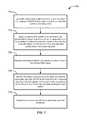
- the methodcan include emitting light pulses from a light source in a light detection and ranging (LIDAR) device toward a reflective side of a mirror.
- the methodcan also include applying an alternating current to a conductive coil coupled to the mirror while emitting the series of light pulses.
- the conductive coilcan be oriented in a plane substantially perpendicular to an axis of rotation of the mirror.
- the axis of rotation of the mirrorcan be oriented substantially parallel to the reflective side of the mirror and situated between the reflective side of the mirror and the conductive coil.
- At least one magnetcan be arranged such that current flowing through the conductive coil urges the conductive coil in a direction perpendicular to both the magnetic field and the direction of current flow so as to generate a torque on the mirror about the axis of rotation such that the applied alternating current causes the mirror to oscillate according to the amplitude and frequency of the applied alternating current.
- the methodcan also include receiving returning reflected signals corresponding to the emitted light pulses.
- the methodcan also include identifying obstacles surrounding an autonomous vehicle associated with the LIDAR device based on the received returning reflected signals and based on the orientations of the mirror in the LIDAR device while emitting the light pulses.
- the methodcan also include controlling the autonomous vehicle to avoid the identified obstacles.
- a light detection and ranging (LIDAR) devicecomprising a rotating mirror system, and a light source.
- the rotating mirror systemcan include: a mirror body, a driving circuit, at least one magnet with an associated magnetic field, and means for magnetically driving the mirror to rotate according to signals from the driving circuit.
- the light sourcecan be configured to emit light pulses directed toward the rotating mirror system such that the light pulses are reflected by the reflective side and emitted from the LIDAR device according to the orientation of the reflective side.
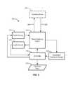
- FIG. 1is a functional block diagram depicting aspects of an example autonomous vehicle.
- FIG. 2depicts exterior views of an example autonomous vehicle.
- FIG. 3is a block diagram of an example LIDAR system.
- FIG. 4Ais a diagram of an example LIDAR system that scans a scanning zone via an oscillating mirror.
- FIG. 4Bis a diagram of an example LIDAR system that employs multiple light sources reflected from an oscillating mirror to scan a scanning zone.
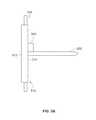
- FIG. 5Ais a side view of an example magnetically driven mirror.
- FIG. 5Bis a top view of the example magnetically driven mirror shown in FIG. 5A .
- FIG. 5Cis a rear aspect view of the example magnetically driven mirror shown in FIGS. 5A and 5B .
- FIG. 5Dis a top view of the example magnetically driven mirror shown in FIGS. 5A-5C showing a magnetic circuit containing yoke.
- FIG. 5Eis a cross-sectional view illustrating an example arrangement of permanent magnets mounted to the yoke to generate a magnetic field for interacting with the conductive coil connected to the example magnetically driven mirror.
- FIG. 5Fis a diagram illustrating example current direction, magnetic field direction, and force direction with the mirror at a maximum displacement angle.
- FIG. 5Gis a diagram illustrating example current direction, magnetic field direction, and force direction with the mirror at zero displacement angle.
- FIG. 5His a diagram illustrating example current direction, magnetic field direction, and force direction with the mirror at a maximum negative displacement angle.
- FIG. 6Ashows a disk for an optical encoder connected to the example magnetically driven mirror shown in FIG. 5 .
- FIG. 6Bshows an assembled oscillating mirror system according to an example embodiment.
- FIG. 7is a flowchart of a process for operating a LIDAR system according to an example embodiment.
- FIG. 8depicts a non-transitory computer-readable medium configured according to an example embodiment.
- Example embodimentsrelate to an autonomous vehicle, such as a driverless automobile, that includes a light detection and ranging (LIDAR) sensor for actively detecting reflective features in the environment surrounding the vehicle.
- a controlleranalyzes information from the LIDAR sensor to identify the surroundings of the vehicle. The controller determines how to direct the propulsion systems of the vehicle to effect a navigation path that substantially avoids obstacles indicated by the information from the LIDAR sensor.
- LIDARlight detection and ranging
- Each distance measurement of a scanning LIDARis associated with a point or “spot” on a reflective feature in the environment surrounding the LIDAR from which an emitted pulse is reflected. Scanning the LIDAR through a range of orientations provides a three-dimensional distribution of reflective points, which is referred to herein as a 3-D point map or 3-D point cloud. Spatial features that appear in a 3-D point map generally correspond to objects detected by laser pulses from the LIDAR that bounce off the objects' surfaces as the LIDAR scans across a scanning zone.
- a LIDAR deviceincludes a rotating mirror driven by a conductive coil that generates torque on the mirror by interacting with a magnetic field.
- the conductive coilcan be embedded in a printed circuit board attached to the back side of the rotating mirror.
- the printed circuit boardextends outward from the mirror in a plane substantially perpendicular to the axis of rotation of the mirror.
- the conductive coilcan be oriented in a plane substantially perpendicular to the axis of rotation of the mirror.
- Magnetsare arranged to generate a magnetic field that interacts with current carried by the conductive coil to apply torque on the mirror.
- a pair of magnetscan be situated on the same side of the conductive coil with one having its North polarity faced toward the coil and the other having its South polarity faced toward the coil.
- the two magnetscan create a magnetic field with a first region in the vicinity of a first radial section of the conductive coil where the local magnetic field is oriented in a first direction parallel to the axis of rotation.
- the magnetic fieldmay also have a second region in the vicinity of a second radial section of the conductive coil where the local magnetic field is oriented in a second direction antiparallel to the first direction.
- the magnetic field associated with the magnetscan be directed in opposite directions on opposite sides of the conductive coil.
- the magnetsmay also be mounted to a ferromagnetic yoke to substantially confine the magnetic field to the region surrounding the conductive coil.
- the ferromagnetic yokemay, for example, complete a magnetic circuit between the two magnets.
- Applying an oscillating current to the conductive loopcauses the mirror to undergo oscillatory motion with an angular deflection amplitude and frequency that depend on the amplitude and frequency of the applied alternating current.
- the permanent magnets and yokecan remain fixed as the mirror rotates.
- a housingmay be provided for mounting the permanent magnets.
- the mirrormay then be rotatably mounted to the housing, for example, by situating a pivot rod within a seating in the housing that allows the mirror to rotate with respect to the housing.
- One or more springscan be connected to the oscillating mirror to create a resonance condition on the oscillatory motion of the mirror.
- a pair of springscan be connected between side edges of the mirror at a point away from the axis of rotation and anchored to the housing. The pair of springs can then compress and stretch, respectively, while the mirror oscillates away from its nominal, non-rotated position. The springs may then combine to contribute torque urging the mirror to return to its nominal, non-rotated position whenever the mirror oscillates away from the nominal position, and the force from the springs can be at least roughly proportionate to the angular displacement from the nominal position.
- One or more torsional springs wrapped around the axis of rotationmay also be used to create a resonance condition on the oscillatory motion of the mirror.
- the resonant frequency of the oscillatory mirrorcan then be tuned by adjusting the properties of the springs to create a system with a desired frequency response.
- an optical encodercan be used to monitor the position of the mirror as it rotates.
- a disk with a pattern of cut outs and/or tick markscan be fixed to the mirror and a light sensor can be fixed relative to the permanent magnets and/or housing. The light sensor can be used to count the tick marks as the mirror rotates to provide feedback on the orientation of the mirror.
- the example systemmay include one or more processors, one or more forms of memory, one or more input devices/interfaces, one or more output devices/interfaces, and machine-readable instructions that when executed by the one or more processors cause the system to carry out the various functions, tasks, capabilities, etc., described above.
- Some aspects of the example methods described hereinmay be carried out in whole or in part by an autonomous vehicle or components thereof. However, some example methods may also be carried out in whole or in part by a system or systems that are remote from an autonomous vehicle. For instance, an example method could be carried out in part or in full by a server system, which receives information from sensors (e.g., raw sensor data and/or information derived therefrom) of an autonomous vehicle. Other examples are also possible.
- sensorse.g., raw sensor data and/or information derived therefrom
- An example systemmay be implemented in, or may take the form of, an automobile.
- an example systemmay also be implemented in or take the form of other vehicles, such as cars, trucks, motorcycles, buses, boats, airplanes, helicopters, lawn mowers, earth movers, boats, snowmobiles, aircraft, recreational vehicles, amusement park vehicles, farm equipment, construction equipment, trams, golf carts, trains, and trolleys.
- Other vehiclesare possible as well.
- FIG. 1is a functional block diagram illustrating a vehicle 100 according to an example embodiment.
- the vehicle 100is configured to operate fully or partially in an autonomous mode, and thus may be referred to as an “autonomous vehicle.”
- a computer system 112can control the vehicle 100 while in an autonomous mode via control instructions to a control system 106 for the vehicle 100 .
- the computer system 112can receive information from one or more sensor systems 104 , and base one or more control processes (such as setting a heading so as to avoid a detected obstacle) upon the received information in an automated fashion.
- the autonomous vehicle 100can be fully autonomous or partially autonomous. In a partially autonomous vehicle some functions can optionally be manually controlled (e.g., by a driver) some or all of the time. Further, a partially autonomous vehicle can be configured to switch between a fully-manual operation mode and a partially-autonomous and/or a fully-autonomous operation mode.
- the vehicle 100includes a propulsion system 102 , a sensor system 104 , a control system 106 , one or more peripherals 108 , a power supply 110 , a computer system 112 , and a user interface 116 .
- the vehicle 100may include more or fewer subsystems and each subsystem can optionally include multiple components. Further, each of the subsystems and components of vehicle 100 can be interconnected and/or in communication. Thus, one or more of the functions of the vehicle 100 described herein can optionally be divided between additional functional or physical components, or combined into fewer functional or physical components. In some further examples, additional functional and/or physical components may be added to the examples illustrated by FIG. 1 .
- the propulsion system 102can include components operable to provide powered motion to the vehicle 100 .
- the propulsion system 102includes an engine/motor 118 , an energy source 119 , a transmission 120 , and wheels/tires 121 .
- the engine/motor 118converts energy source 119 to mechanical energy.
- the propulsion system 102can optionally include one or both of engines and/or motors.
- a gas-electric hybrid vehiclecan include both a gasoline/diesel engine and an electric motor.
- the energy source 119represents a source of energy, such as electrical and/or chemical energy, that may, in full or in part, power the engine/motor 118 . That is, the engine/motor 118 can be configured to convert the energy source 119 to mechanical energy to operate the transmission.
- the energy source 119can include gasoline, diesel, other petroleum-based fuels, propane, other compressed gas-based fuels, ethanol, solar panels, batteries, capacitors, flywheels, regenerative braking systems, and/or other sources of electrical power, etc.
- the energy source 119can also provide energy for other systems of the vehicle 100 .
- the transmission 120includes appropriate gears and/or mechanical elements suitable to convey the mechanical power from the engine/motor 118 to the wheels/tires 121 .
- the transmission 120includes a gearbox, a clutch, a differential, a drive shaft, and/or axle(s), etc.
- the wheels/tires 121are arranged to stably support the vehicle 100 while providing frictional traction with a surface, such as a road, upon which the vehicle 100 moves. Accordingly, the wheels/tires 121 are configured and arranged according to the nature of the vehicle 100 .
- the wheels/tirescan be arranged as a unicycle, bicycle, motorcycle, tricycle, or car/truck four-wheel format. Other wheel/tire geometries are possible, such as those including six or more wheels. Any combination of the wheels/tires 121 of vehicle 100 may be operable to rotate differentially with respect to other wheels/tires 121 .
- the wheels/tires 121can optionally include at least one wheel that is rigidly attached to the transmission 120 and at least one tire coupled to a rim of a corresponding wheel that makes contact with a driving surface.
- the wheels/tires 121may include any combination of metal and rubber, and/or other materials or combination of materials.
- the sensor system 104generally includes one or more sensors configured to detect information about the environment surrounding the vehicle 100 .
- the sensor system 104can include a Global Positioning System (GPS) 122 , an inertial measurement unit (IMU) 124 , a RADAR unit 126 , a laser rangefinder/LIDAR unit 128 , a camera 130 , and/or a microphone 131 .
- the sensor system 104could also include sensors configured to monitor internal systems of the vehicle 100 (e.g., O 2 monitor, fuel gauge, engine oil temperature, wheel speed sensors, etc.).
- One or more of the sensors included in sensor system 104could be configured to be actuated separately and/or collectively in order to modify a position and/or an orientation of the one or more sensors.
- the GPS 122is a sensor configured to estimate a geographic location of the vehicle 100 .
- GPS 122can include a transceiver operable to provide information regarding the position of the vehicle 100 with respect to the Earth.
- the IMU 124can include any combination of sensors (e.g., accelerometers and gyroscopes) configured to sense position and orientation changes of the vehicle 100 based on inertial acceleration.
- sensorse.g., accelerometers and gyroscopes
- the RADAR unit 126can represent a system that utilizes radio signals to sense objects within the local environment of the vehicle 100 .
- the RADAR unit 126 and/or the computer system 112can additionally be configured to sense the speed and/or heading of the objects.
- the laser rangefinder or LIDAR unit 128can be any sensor configured to sense objects in the environment in which the vehicle 100 is located using lasers.
- the laser rangefinder/LIDAR unit 128can include one or more laser sources, a laser scanner, and one or more detectors, among other system components.
- the laser rangefinder/LIDAR unit 128can be configured to operate in a coherent (e.g., using heterodyne detection) or an incoherent detection mode.
- the camera 130can include one or more devices configured to capture a plurality of images of the environment surrounding the vehicle 100 .
- the camera 130can be a still camera or a video camera.
- the camera 130can be mechanically movable such as by rotating and/or tilting a platform to which the camera is mounted. As such, a control process of vehicle 100 may be implemented to control the movement of camera 130 .
- the sensor system 104can also include a microphone 131 .
- the microphone 131can be configured to capture sound from the environment surrounding vehicle 100 .
- multiple microphonescan be arranged as a microphone array, or possibly as multiple microphone arrays.
- the control system 106is configured to control operation(s) regulating acceleration of the vehicle 100 and its components. To effect acceleration, the control system 106 includes a steering unit 132 , throttle 134 , brake unit 136 , a sensor fusion algorithm 138 , a computer vision system 140 , a navigation/pathing system 142 , and/or an obstacle avoidance system 144 , etc.
- the steering unit 132is operable to adjust the heading of vehicle 100 .
- the steering unitcan adjust the axis (or axes) of one or more of the wheels/tires 121 so as to effect turning of the vehicle.
- the throttle 134is configured to control, for instance, the operating speed of the engine/motor 118 and, in turn, adjust forward acceleration of the vehicle 100 via the transmission 120 and wheels/tires 121 .
- the brake unit 136decelerates the vehicle 100 .
- the brake unit 136can use friction to slow the wheels/tires 121 .
- the brake unit 136inductively decelerates the wheels/tires 121 by a regenerative braking process to convert kinetic energy of the wheels/tires 121 to electric current.
- the sensor fusion algorithm 138is an algorithm (or a computer program product storing an algorithm) configured to accept data from the sensor system 104 as an input.
- the datamay include, for example, data representing information sensed at the sensors of the sensor system 104 .
- the sensor fusion algorithm 138can include, for example, a Kalman filter, Bayesian network, etc.
- the sensor fusion algorithm 138provides assessments regarding the environment surrounding the vehicle based on the data from sensor system 104 .
- the assessmentscan include evaluations of individual objects and/or features in the environment surrounding vehicle 100 , evaluations of particular situations, and/or evaluations of possible interference between the vehicle 100 and features in the environment (e.g., such as predicting collisions and/or impacts) based on the particular situations.
- the computer vision system 140can process and analyze images captured by camera 130 to identify objects and/or features in the environment surrounding vehicle 100 .
- the detected features/objectscan include traffic signals, road way boundaries, other vehicles, pedestrians, and/or obstacles, etc.
- the computer vision system 140can optionally employ an object recognition algorithm, a Structure From Motion (SFM) algorithm, video tracking, and/or available computer vision techniques to effect categorization and/or identification of detected features/objects.
- SFMStructure From Motion
- the computer vision system 140can be additionally configured to map the environment, track perceived objects, estimate the speed of objects, etc.
- the navigation and pathing system 142is configured to determine a driving path for the vehicle 100 .
- the navigation and pathing system 142can determine a series of speeds and directional headings to effect movement of the vehicle along a path that substantially avoids perceived obstacles while generally advancing the vehicle along a roadway-based path leading to an ultimate destination, which can be set according to user inputs via the user interface 116 , for example.
- the navigation and pathing system 142can additionally be configured to update the driving path dynamically while the vehicle 100 is in operation on the basis of perceived obstacles, traffic patterns, weather/road conditions, etc.
- the navigation and pathing system 142can be configured to incorporate data from the sensor fusion algorithm 138 , the GPS 122 , and one or more predetermined maps so as to determine the driving path for vehicle 100 .
- the obstacle avoidance system 144can represent a control system configured to identify, evaluate, and avoid or otherwise negotiate potential obstacles in the environment surrounding the vehicle 100 .
- the obstacle avoidance system 144can effect changes in the navigation of the vehicle by operating one or more subsystems in the control system 106 to undertake swerving maneuvers, turning maneuvers, braking maneuvers, etc.
- the obstacle avoidance system 144is configured to automatically determine feasible (“available”) obstacle avoidance maneuvers on the basis of surrounding traffic patterns, road conditions, etc.
- availablefeasible
- the obstacle avoidance system 144can be configured such that a swerving maneuver is not undertaken when other sensor systems detect vehicles, construction barriers, other obstacles, etc. in the region adjacent the vehicle that would be swerved into.
- the obstacle avoidance system 144can automatically select the maneuver that is both available and maximizes safety of occupants of the vehicle. For example, the obstacle avoidance system 144 can select an avoidance maneuver predicted to cause the least amount of acceleration in a passenger cabin of the vehicle 100 .
- the vehicle 100also includes peripherals 108 configured to allow interaction between the vehicle 100 and external sensors, other vehicles, other computer systems, and/or a user, such as an occupant of the vehicle 100 .
- the peripherals 108 for receiving information from occupants, external systems, etc.can include a wireless communication system 146 , a touchscreen 148 , a microphone 150 , and/or a speaker 152 .
- the peripherals 108function to receive inputs for a user of the vehicle 100 to interact with the user interface 116 .
- the touchscreen 148can both provide information to a user of vehicle 100 , and convey information from the user indicated via the touchscreen 148 to the user interface 116 .
- the touchscreen 148can be configured to sense both touch positions and touch gestures from a user's finger (or stylus, etc.) via capacitive sensing, resistance sensing, optical sensing, a surface acoustic wave process, etc.
- the touchscreen 148can be capable of sensing finger movement in a direction parallel or planar to the touchscreen surface, in a direction normal to the touchscreen surface, or both, and may also be capable of sensing a level of pressure applied to the touchscreen surface.
- An occupant of the vehicle 100can also utilize a voice command interface.
- the microphone 150can be configured to receive audio (e.g., a voice command or other audio input) from a user of the vehicle 100 .
- the speakers 152can be configured to output audio to the user of the vehicle 100 .
- the peripherals 108function to allow communication between the vehicle 100 and external systems, such as devices, sensors, other vehicles, etc. within its surrounding environment and/or controllers, servers, etc., physically located far from the vehicle that provide useful information regarding the vehicle's surroundings, such as traffic information, weather information, etc.
- the wireless communication system 146can wirelessly communicate with one or more devices directly or via a communication network.
- the wireless communication system 146can optionally use 3G cellular communication, such as CDMA, EVDO, GSM/GPRS, and/or 4 G cellular communication, such as WiMAX or LTE.
- wireless communication system 146can communicate with a wireless local area network (WLAN), for example, using WiFi.
- WLANwireless local area network
- wireless communication system 146could communicate directly with a device, for example, using an infrared link, Bluetooth, and/or ZigBee.
- the wireless communication system 146can include one or more dedicated short range communication (DSRC) devices that can include public and/or private data communications between vehicles and/or roadside stations.
- DSRCdedicated short range communication
- Other wireless protocols for sending and receiving information embedded in signals, such as various vehicular communication systems,can also be employed by the wireless communication system 146 within the context of the present disclosure.
- the power supply 110can provide power to components of vehicle 100 , such as electronics in the peripherals 108 , computer system 112 , sensor system 104 , etc.
- the power supply 110can include a rechargeable lithium-ion or lead-acid battery for storing and discharging electrical energy to the various powered components, for example.
- one or more banks of batteriescan be configured to provide electrical power.
- the power supply 110 and energy source 119can be implemented together, as in some all-electric cars.
- Computer system 112that receives inputs from the sensor system 104 , peripherals 108 , etc., and communicates appropriate control signals to the propulsion system 102 , control system 106 , peripherals, etc. to effect automatic operation of the vehicle 100 based on its surroundings.
- Computer system 112includes at least one processor 113 (which can include at least one microprocessor) that executes instructions 115 stored in a non-transitory computer readable medium, such as the data storage 114 .
- the computer system 112may also represent a plurality of computing devices that serve to control individual components or subsystems of the vehicle 100 in a distributed fashion.
- data storage 114contains instructions 115 (e.g., program logic) executable by the processor 113 to execute various functions of vehicle 100 , including those described above in connection with FIG. 1 .
- Data storage 114may contain additional instructions as well, including instructions to transmit data to, receive data from, interact with, and/or control one or more of the propulsion system 102 , the sensor system 104 , the control system 106 , and the peripherals 108 .
- the data storage 114may store data such as roadway maps, path information, among other information. Such information may be used by vehicle 100 and computer system 112 during operation of the vehicle 100 in the autonomous, semi-autonomous, and/or manual modes to select available roadways to an ultimate destination, interpret information from the sensor system 104 , etc.
- the vehicle 100provides information to and/or receives input from, a user of vehicle 100 , such as an occupant in a passenger cabin of the vehicle 100 .
- the user interface 116can accordingly include one or more input/output devices within the set of peripherals 108 , such as the wireless communication system 146 , the touchscreen 148 , the microphone 150 , and/or the speaker 152 to allow communication between the computer system 112 and a vehicle occupant.
- the computer system 112controls the operation of the vehicle 100 based on inputs received from various subsystems indicating vehicle and/or environmental conditions (e.g., propulsion system 102 , sensor system 104 , and/or control system 106 ), as well as inputs from the user interface 116 , indicating user preferences.
- the computer system 112can utilize input from the control system 106 to control the steering unit 132 to avoid an obstacle detected by the sensor system 104 and the obstacle avoidance system 144 .
- the computer system 112can be configured to control many aspects of the vehicle 100 and its subsystems. Generally, however, provisions are made for manually overriding automated controller-driven operation, such as in the event of an emergency, or merely in response to a user-activated override, etc.
- the components of vehicle 100 described hereincan be configured to work in an interconnected fashion with other components within or outside their respective systems.
- the camera 130can capture a plurality of images that represent information about an environment of the vehicle 100 while operating in an autonomous mode.
- the environmentmay include other vehicles, traffic lights, traffic signs, road markers, pedestrians, etc.
- the computer vision system 140can categorize and/or recognize various aspects in the environment in concert with the sensor fusion algorithm 138 , the computer system 112 , etc. based on object recognition models pre-stored in data storage 114 , and/or by other techniques.
- vehicle 100is described and shown in FIG. 1 as having various components of vehicle 100 , e.g., wireless communication system 146 , computer system 112 , data storage 114 , and user interface 116 , integrated into the vehicle 100 , one or more of these components can optionally be mounted or associated separately from the vehicle 100 .
- data storage 114can exist, in part or in full, separate from the vehicle 100 , such as in a cloud-based server, for example.
- one or more of the functional elements of the vehicle 100can be implemented in the form of device elements located separately or together.
- the functional device elements that make up vehicle 100can generally be communicatively coupled together in a wired and/or wireless fashion.
- FIG. 2shows an example vehicle 200 that can include some or all of the functions described in connection with vehicle 100 in reference to FIG. 1 .
- vehicle 200is illustrated in FIG. 2 as a four-wheel sedan-type car for illustrative purposes, the present disclosure is not so limited.
- the vehicle 200can represent a truck, a van, a semi-trailer truck, a motorcycle, a golf cart, an off-road vehicle, or a farm vehicle, etc.
- the example vehicle 200includes a sensor unit 202 , a wireless communication system 204 , a RADAR unit 206 , a laser rangefinder unit 208 , and a camera 210 . Furthermore, the example vehicle 200 can include any of the components described in connection with vehicle 100 of FIG. 1 .
- the RADAR unit 206 and/or laser rangefinder unit 208can actively scan the surrounding environment for the presence of potential obstacles and can be similar to the RADAR unit 126 and/or laser rangefinder/LIDAR unit 128 in the vehicle 100 .
- the sensor unit 202is mounted atop the vehicle 200 and includes one or more sensors configured to detect information about an environment surrounding the vehicle 200 , and output indications of the information.
- sensor unit 202can include any combination of cameras, RADARs, LIDARs, range finders, and acoustic sensors.
- the sensor unit 202can include one or more movable mounts that could be operable to adjust the orientation of one or more sensors in the sensor unit 202 .
- the movable mountcould include a rotating platform that could scan sensors so as to obtain information from each direction around the vehicle 200 .
- the movable mount of the sensor unit 202could be moveable in a scanning fashion within a particular range of angles and/or azimuths.
- the sensor unit 202could be mounted atop the roof of a car, for instance, however other mounting locations are possible. Additionally, the sensors of sensor unit 202 could be distributed in different locations and need not be collocated in a single location. Some possible sensor types and mounting locations include those locations illustrated in connection with RADAR unit 206 and laser rangefinder unit 208 . Furthermore, each sensor of sensor unit 202 can be configured to be moved or scanned independently of other sensors of sensor unit 202 .
- the wireless communication system 204can be located on a roof of the vehicle 200 as depicted in FIG. 2 . Alternatively, the wireless communication system 204 can be located, fully or partially, elsewhere on the vehicle 200 .
- the wireless communication system 204may include wireless transmitters and receivers that may be configured to communicate with devices external or internal to the vehicle 200 .
- the wireless communication system 204can include transceivers configured to communicate with other vehicles and/or computing devices, for instance, in a vehicular communication system or a roadway station. Examples of such vehicular communication systems include dedicated short range communications (DSRC), radio frequency identification (RFID), and other proposed communication standards directed towards intelligent transport systems.
- DSRCdedicated short range communications
- RFIDradio frequency identification
- the camera 210can be a photo-sensitive instrument, such as a still camera, a video camera, etc., that is configured to capture a plurality of images of the environment of the vehicle 200 .
- the camera 210can be configured to detect visible light, and can additionally or alternatively be configured to detect light from other portions of the spectrum, such as infrared or ultraviolet light.
- the camera 210can be a two-dimensional detector, and can optionally have a three-dimensional spatial range of sensitivity.
- the camera 210can include, for example, a range detector configured to generate a two-dimensional image indicating distance from the camera 210 to a number of points in the environment. Accordingly, the camera 210 may use one or more range detecting techniques.
- the camera 210can provide range information by using a structured light technique in which the vehicle 200 illuminates an object in the environment with a predetermined light pattern, such as a grid or checkerboard pattern and uses the camera 210 to detect a reflection of the predetermined light pattern from environmental surroundings. Based on distortions in the reflected light pattern, the vehicle 200 can determine the distance to the points on the object.
- the predetermined light patternmay comprise infrared light, or radiation at other suitable wavelengths for such measurements.
- the camera 210can be mounted inside a front windshield of the vehicle 200 . Specifically, the camera 210 can be situated to capture images from a forward-looking view with respect to the orientation of the vehicle 200 . Other mounting locations and viewing angles of camera 210 can also be used, either inside or outside the vehicle 200 .
- the camera 210can have associated optics operable to provide an adjustable field of view. Further, the camera 210 can be mounted to vehicle 200 with a movable mount to vary a pointing angle of the camera 210 , such as via a pan/tilt mechanism.
- FIG. 3is a block diagram of an example LIDAR device 300 .
- the LIDAR device 300includes a light source 310 , beam-steering optics 312 , a light sensor 314 , and a controller 316 .
- the light source 310may emit pulses of light toward the beam-steering optics 312 , which directs the pulses of light 304 across a scanning zone 302 .
- Reflective features in the scanning zone 302reflect the pulses of light 304 and the reflected light signals 306 can be detected by the light sensor 314 .
- the controller 316regulates the operation of the light source 310 and beam-steering optics 312 to scan pulses of light 304 across the scanning zone 302 .
- the controller 316can also be configured to estimate positions of reflective features in the scanning zone 302 based on the reflected signals 306 detected by the light sensor 314 .
- the controller 316can measure the time delay between emission of a pulse of light and reception of a reflected light signal and determine the distance to the reflective feature based on the time of flight of a round trip to the reflective feature.
- the controller 316may use the orientation of the beam-steering optics 312 at the time the pulse of light is emitted to estimate a direction toward the reflective feature.
- an orientation feedback system 318can send information to the controller 316 indicating the orientation of the beam-steering optics 312 (and thus the direction of the emitted pulse of light).
- the estimated direction(e.g., from the orientation feedback system 318 ) and estimated distance (e.g., based on a measured time delay) can be combined to estimate a three-dimensional position from which the returning light signal 306 was reflected.
- the controller 316may combine a series of three-dimensional position estimations (e.g., from each received reflected light signal 306 ) from across the scanning zone 302 to generate a three-dimensional point map 320 of reflective features in the scanning zone 302 .
- the light source 310can be a laser light source that emits light in the visible, infrared, and/or ultraviolet spectrum. Moreover, the light source 310 can optionally include a plurality of light sources each emitting pulses of light. In an example with multiple light sources, each light source may be directed to the scanning zone 302 by the beam-steering optics 312 . For example, a group of light sources can each be aimed at a single rotating mirror. The group of light sources can be aimed such that each light source reflects from the mirror at a distinct angle and therefore scans a substantially distinct region of the scanning zone 302 . Additionally or alternatively, the light sources may scan wholly or partially overlapping regions of the scanning zone 302 . Additionally or alternatively, more than one beam-steering optical device can be provided, and each such beam-steering optical device can direct light pulses from one or more light sources.
- the reflected light signalsmay be directed to the light sensor 314 by the beam-steering optics 312 .
- thisis just one configuration provided for example purposes.
- Some embodiments of the LIDAR device 300may be arranged with a light sensor configured to receive reflected light from the scanning zone 302 without first being directed via the beam-steering optics 312 .
- the controller 316is configured to control the operation of the light source 310 and the beam-steering optics 312 to cause pulses of light 304 to be emitted across the scanning zone 302 .
- the controller 316also receives information from the light sensor 314 to indicate the reception of reflected light signals 306 at the light sensor 314 .
- the controller 316can then determine the distance to surrounding objects by determining the time delay between emission of a light pulse and reception of a corresponding reflected light signal.
- the time delayindicates the round trip travel time of the emitted light from the LIDAR device 300 and a reflective feature in the scanning zone 302 .
- a distance to a reflective featuremay be estimated by dividing the time delay by the speed of light, for example.
- the three-dimensional position of the reflective featurecan then be estimated by combining the estimated distance with the orientation of the beam-steering optics 312 during the emission of the pulse.
- the orientation of the beam-steering optics 312can be detected by an orientation feedback system 318 configured to sense the orientation of the beam-steering optics 312 .
- the orientation feedback system 318can then provide an indication of the orientation of the beam-steering optics 312 to the controller 316 and use the orientation information to estimate three-dimensional positions associated with received reflected light signals.
- the LIDAR device 300can be used to locate reflective features in the scanning zone 302 .
- Each reflected light signal received at the light sensor 314may be associated with a three-dimensional point in space based on the measured time delay and orientation of the beam-steering optics 312 associated with each reflected light signal.
- the combined group of three-dimensional points following a scan of the scanning zone 302can be combined together to create a 3-D point map 320 , which may be output from the LIDAR device 300 .
- the 3-D point map 320may then be analyzed by one or more functional modules used to control an autonomous vehicle.
- the 3-D point map 320may be used by the obstacle avoidance system 144 and/or navigation/pathing system 142 in the vehicle 100 to identify obstacles surrounding the vehicle 100 and/or to control the vehicle 100 to avoid interference with such obstacles.
- the beam-steering optics 312may include one or more mirrors, lenses, filters, prisms, etc., configured to direct light pulses from the light source 310 to the scanning zone 302 .
- the beam-steering optics 312may be configured to direct the light pulses according to an orientation indicated by signals from the controller 316 .
- the beam-steering optics 312may include one or more mirrors configured to rotate and/or oscillate according to signals from the controller 316 .
- the controller 316can thereby control the direction of emission of light pulse(s) 304 from the LIDAR device 300 by providing suitable control signals to the beam-steering optics 312 .
- the beam-steering optics 312can be operated to scan the light from the light source 310 across the scanning zone 302 at a regular interval (e.g., to complete a full scan of the scanning zone 302 periodically).
- the LIDAR device 300may be used to dynamically generate three-dimensional point maps of reflecting features in the scanning zone 302 .
- the three-dimensional mapmay be updated at a frequency that is sufficient to provide information useful for real time navigation and/or obstacle avoidance for an autonomous vehicle (e.g., the autonomous vehicles 100 , 200 discussed above in connection with FIGS. 1-2 ).
- the 3-D point map 320may be refreshed at a frequency of about 10 hertz to about 100 hertz and such refreshed point map information may be used to identify obstacles of an autonomous vehicle on which the LIDAR device 300 is mounted and then control the vehicle to avoid interference with such obstacles.
- FIG. 4Ais a diagram of an example LIDAR system 400 that scans a scanning zone 430 via an oscillating mirror 420 .
- the example LIDAR system 400includes a light source 410 arranged to emit pulses of light at a reflective surface 424 of the oscillating mirror 420 .
- the LIDAR system 400may also include a light sensor (not shown), orientation feedback system (not shown), and controller (not shown), similar to those described above in connection with FIG. 3 .
- the LIDAR system 400 illustrated in FIG. 4may be configured to detect returning reflected light signals and use the reflected light signals to generate a three-dimensional point map of reflective features in the scanning zone 430 .
- the oscillating mirror 420can rotate about its axis 422 .
- the axis 422may be defined by, for example, a pivot rod oriented parallel to the reflective surface 424 of the mirror 420 .
- the oscillating mirror 420can be driven to oscillate back and forth (as indicated by the motion arrow 426 ) such that the light from the light source 410 sweeps across an angle ⁇ .
- the scanning zone 430may therefore be a region defined by a cone having an apex approximately located at the oscillating mirror 420 and with opening angle ⁇ .
- the mirror 420may be driven to oscillate with a frequency of about 60 hertz, which may also be the refresh rate of the LIDAR system 400 .
- FIG. 4Bis a diagram of an example LIDAR system 440 with multiple light sources 452 - 456 each scanning a portion of a scanning zone.
- FIG. 4Bshows the system 440 with three light sources (i.e., the first light source 452 , second light source 454 , and third light source 456 ).
- the light sources 452 - 456can be arranged such that light emitted from each is directed toward a reflective side (not visible) of an oscillating mirror 460 .
- the light sources 452 - 456can each emit light from a distinct position such that pulses of light emitted from each of the light sources 452 - 456 define an angle with respect to one another.
- the first light source 452 and second light source 454can emit light from distinct positions that are separated by an angle ⁇ when the light emitted from each is aimed at the oscillating mirror 460 .
- the second light source 454 and third light source 456can be arranged such that light emitted from the two light sources 454 , 456 defines an angle ⁇ when the light emitted from each is aimed at the oscillating mirror 460 .
- the oscillating mirror 460can scan each light source across a respective scanning zone (e.g., the scanning zones 472 - 476 ).
- the light sources 452 - 456can be stacked in a vertical height direction substantially parallel to the axis of rotation 462 of the oscillating mirror.
- each of scanning zones 472 - 476can have an azimuthal span due to the oscillation of the mirror 460 similar to the azimuthal span of the scanning zone 430 in FIG. 4A .
- the scanning zones 472 - 476can each azimuthally span the angle ⁇ identified in FIG. 4B .
- the scanning zones 472 - 476can be separated in altitude by a characteristic angle ⁇ ′ that corresponds to the separation angle ⁇ between the directions of the light sources 452 - 456 .
- each scanning zonemay be the same (e.g., ⁇ ).
- the angular separation between the light sources 452 - 456(e.g., the angle ⁇ ) may cause the emitted light pulses from each of the light sources 452 - 456 to scan across a distinct scanning zone.
- each light source 452 - 456can be associated with a distinct scanning zone.
- the first light source 452can be scanned across the first scanning zone 472 ;
- the second light source 454can be scanned across the second scanning zone 474 ;
- the third light source 456can be scanned across the third scanning zone 476 .
- the scanning zonesmay include at least partially overlapping regions, as illustrated for example purposes in FIG. 4B .
- the scanning zones 472 - 476are identified separately for convenience in explaining the arrangement with multiple angularly offset light sources.
- information from the multiple scanning zonescan be combined (e.g., via a controller) to create a combined three-dimensional point map for use by navigation and/or obstacle avoidance systems of an autonomous vehicle (e.g., the autonomous vehicles 100 , 200 described in connection with FIGS. 1 and 2 above).
- the LIDAR system 440is shown with three light sources (e.g., the light sources 452 - 456 ) each directed at a single oscillating mirror 460 to scan three scanning zones (e.g., the scanning zones 472 - 476 ). However, some embodiments of the present disclosure may include more than three light sources and more than three scanning zones.
- the oscillating mirror 460may oscillate to cause the light from each light source to scan a region with an opening angle of approximately 8°. For example, the oscillating mirror 460 may oscillate back and forth plus and minus 4° from a nominal position such that the pulses of light from the light sources are scanned across their respective scanning zones with approximately 8° azimuthal angular span.
- FIG. 5Ais a side view of an example magnetically driven mirror 510 .
- the mirror 510includes a mirror body with a reflective surface 512 and a back surface 514 opposite the reflective surface 512 .
- the mirror 510rotates about an axis of rotation parallel to the reflective surface.
- the axis of rotationis defined by a pivot rod 516 .
- the pivot rod 516may pass through the mirror body to allow the mirror body to rotate around the pivot rod 516 while the pivot rod 516 remains fixed.
- the pivot rod 516may also be securely connected to the mirror body to allow the mirror body to rotate with the pivot rod 516 .
- the ends of the pivot rod 516may be mounted to a housing so as to allow rotation, such as by seating the pivot rod 516 in divots to allow the pivot rot to rotate with respect to the housing, for example.
- a substrate 520is connected to the back surface 514 of the mirror body.
- a conductive coil(e.g., the coil 530 shown in FIG. 5B ) can be mounted on the substrate 520 .
- the conductive coilcan be operated by driving circuitry to cause the mirror 510 to undergo oscillatory motion about the axis of rotation defined by the pivot rod 516 due to interaction with a magnetic field surrounding the substrate 520 .
- the driving circuitryis situated off of the substrate 520 and electrically connected to the conductive coil through a cable connector 540 , which may be mounted on the substrate 520 and/or the back surface 514 of the mirror body.
- the electrical connection between the driving circuitry and the cable connector 540is made by a wire and/or cable suitable for flexing to follow the oscillatory motion of the mirror 510 , such as a flexible printed circuit (FPC) cable.
- the driving circuitry for the conductive coilcan be mounted directly to the substrate 520 , for example, at the location of the cable connector 540 .
- the reflective surface 512 of the mirror 510can be a surface that reflects light emitted from a light source used in a LIDAR device, such as light with ultraviolet, visible, and/or infrared wavelength(s).
- the mirror 510can be formed of a glass material with a smooth and/or flat surface (e.g., formed by polishing) used to create the reflective surface 512 .
- the reflective surface 512may include a coating of reflective material, such as tin, aluminum, silver, gold, etc. applied to a surface of the mirror body.
- a reflective layere.g., gold coating
- an outer surface of the mirror body materiale.g., glass, aluminum, etc.
- a reflective layercan be applied to an inner surface of mirror body material, and the material of the mirror body (e.g., glass, aluminum, etc.) can then seal and/or protect the reflective layer from the ambient environment. Additionally, the reflective layer may be coated with a transparent coating to preserve the reflective layer by preventing oxidation and/or surface deformation, for example.
- the material of the mirror bodye.g., glass, aluminum, etc.
- the reflective layermay be coated with a transparent coating to preserve the reflective layer by preventing oxidation and/or surface deformation, for example.
- the substrate 520can be a material suitable for mounting a conductive coil and/or other electrical components.
- the substrate 520may be a printed circuit board with wires and/or traces arranged in a coil of conductive material.
- the substrate 520can be oriented in a plane substantially perpendicular to the axis of rotation of the mirror 510 (i.e., the pivot rod 516 ).
- the substrate 520can also be oriented perpendicular to the plane of the reflective surface 512 of the mirror 510 .
- a conductive coil disposed on the substrate 520can be situated in a plane substantially perpendicular to the axis of rotation of the mirror 510 .
- the substrate 520can be mechanically connected to the back surface 514 of the mirror body using one or more adhesives, fasteners, and/or other mounting techniques
- the pivot rod 516 defining the axis of rotation of the mirror 510is situated between the reflective surface 512 of the mirror 510 and the substrate 520 .
- the pivot rod 516may pass through the body of the mirror 510 (e.g., between the reflective surface 512 and the back surface 514 ).
- Situating the axis of rotation of the mirror 510 to pass through the mirror bodymay provide a relatively low moment of inertia for the rotating system and thereby enhance the responsiveness of the system and/or reduce the power needed to drive the oscillation.
- the axis of rotation of the mirror 510may, for example, be situated near the center of mass of the rotating system (e.g., the combination of the mirror 510 and the substrate 520 ).
- FIG. 5Bis a top view of the example magnetically driven mirror 510 shown in FIG. 5A .
- the substrate 520includes a conductive coil 530 that can be electrically connected to the cable connector 540 by leads 542 .
- the substrate 520includes a mirror-proximate shoulder section 522 that is mechanically connected to the back surface 514 of the mirror body (e.g., by adhesives, fasteners, etc.).
- the shoulder section 522may provide a mounting surface for the cable connector 540 that operates the conductive coil 530 via the leads 542 .
- the conductive coil 530 and/or leads 542can be formed of wires and/or traces of conductive material arranged in a continuous coil around the perimeter of the substrate 520 .
- the conductive coil 530is arranged along the perimeter of the substrate 520 , and the substrate 520 has a central cut-out (e.g., an aperture 521 ) from the region surrounded by the conductive coil 530 . Incorporating a central cut-out may, for example, reduce the mass of the substrate 520 and thus the moment of inertia of the mirror 510 . Accordingly, the conductive coil 530 can be disposed on portions of the substrate 520 surrounding the central cut-out.
- the substrate 520can have a first radial leg 524 and a second radial leg 528 joined by an outer concentric side 526 .
- the first and second radial legs 524 , 528can extend along respective radial lines that pass through the axis of rotation of the mirror 510 (e.g., defined by the pivot rod 516 ). That is, the first and second radial legs 524 , 528 can each be connected to the shoulder section 522 and extend to a position distal the mirror 510 along respective lines that are substantially along a radial direction with respect to the axis of rotation of the mirror 510 .
- the outer concentric side 526can connect the mirror-distal positions of the two radial legs 524 , 528 .
- the outer concentric side 526may extend along a concentric ring centered on the axis of rotation of the mirror 510 (e.g., defined by the pivot rod 516 ).
- the conductive coil 530can be wrapped along the path defined by the first and second radial legs 524 , 528 and the outer concentric side 526 of the substrate 520 .
- the conductive coil 530can include a first radial section 532 that includes the length of conductive material that is situated along the first radial leg 524 of the substrate 520 .
- a second radial section 534 of the conductive coil 530includes the length of conductive material that is situated along the second radial leg 528 of the substrate 520 .
- the current through the first and second radial sections 532 , 534is given by the current through the coil 530 multiplied by the number of windings in the coil 530 .
- the current along the first radial section 532is oriented substantially perpendicular to the axis of rotation of the mirror 510 .
- the current along the second radial section 534is also oriented substantially perpendicular to the axis of rotation of the mirror 510 .
- current through the conductive coil 530can generate a Lorentz force that urges the mirror to rotate about its axis of rotation (e.g., defined by the pivot rod 516 ).
- a magnetic field that is oriented into the page near the first radial section 532 and out of the page near the second radial section 534can interact with a clockwise-circulating current in the coil 530 to urge the mirror 510 to rotate in a clockwise direction.
- the Lorentz forces from the two radial sections 532 , 534 while current in the coil 530 is flowing in a clockwise directioneach contribute a clockwise-directed torque on the mirror 510 .
- changing the direction the current to circulate in a counter-clockwise directiongenerates torque on the mirror 510 in a counter-clockwise direction.
- the coil 530 in FIG. 5Bis illustrated to show four windings around the perimeter of the substrate 520 , but this is only for convenience in illustration and explanation.
- Other embodimentsmay include a conductive coil that has a greater or fewer number of windings.
- FIG. 5Cis a rear aspect view of the example magnetically driven mirror 510 shown in FIGS. 5A and 5B .
- the cable connector 540may receive external driving signals from a cable 544 .
- the cable 544can be flexible and arranged with enough slack to remain connected to the cable connector 540 while the mirror 510 undergoes oscillatory motion.
- driving circuitry to operate the conductive coil 530can be located off of the substrate 520 , such as at the not shown end of the cable 544 .
- Driving signals to operate conductive coil 530may then be passed through the cable 544 to the coil 530 via the cable connector 540 , for example.
- the substrate 520is arranged in an outline of a wedge (e.g., similar to a pie slice) with the two radial sections 524 , 528 forming sides, and the outer concentric side 526 forming an outer border.
- the arrangementallows the length of coil along the radial sections 532 , 534 to carry current substantially in a radial direction with respect to the axis of rotation of the mirror 510 while the remaining portions of the coil 530 (e.g., along the outer concentric side 526 and the connection between the radial sections) carry current without a significant radial component.
- the shape of the conductive coil 530may be similar to conductive coils used to drive cones for sound generation in loudspeakers (e.g., “voice coils”).
- the shape of the conductive coil 530may also be similar to conductive coils used to operate rotating arms in hard drive disks.
- FIG. 5Dis a top view of the example magnetically driven mirror 510 shown in FIGS. 5A-5C showing a magnetic circuit containing yoke 550 .
- the yoke 550can have an inner channel between a top portion (visible in FIG. 5D ) and a bottom portion.
- the inner channelcan receive the substrate 520 and allow enough space for the substrate 520 to move back and forth while the mirror 510 oscillates about its axis of rotation (e.g., defined by the pivot rod 516 ).
- FIG. 5Eis a cross-sectional view illustrating an example arrangement of permanent magnets 552 , 554 mounted to the yoke 550 to generate a magnetic field for interacting with the conductive coil 530 connected to the example magnetically driven mirror 510 .
- the view in FIG. 5Edepicts a view from the mirror-distal end of the substrate 520 while looking toward the mirror 510 at a cross-sectional plane perpendicular to the plane of the substrate 520 .
- An arrangement of one or more magnets 552 , 554can be mounted to an inner surface of the yoke 550 to create a magnetic field that is substantially perpendicular to the plane of the substrate 520 .
- the yoke 550can be a ferromagnetic material, such as nickel, iron, etc., that is situated to surround the conductive coil 530 disposed on the substrate 520 .
- the yoke 550 and one or more magnetscan create a magnetic field that is substantially parallel to the axis of rotation of the mirror 510 , and thus perpendicular to the plane of the substrate 520 , in the neighborhood of the radial sections 532 , 534 of the conductive coil 530 .
- the magnets 552 , 554can be oriented to create a magnetic field with opposite direction at the two radial sections 532 , 534 of the conductive coil 530 . That is, the magnetic field within the inner channel of the yoke 550 can have a first direction in the vicinity of the first radial section 532 and an opposite direction (e.g., an anti-parallel direction) in the vicinity of the second radial section 534 . In such an arrangement, torque applied to the mirror 510 due to Lorentz forces from the two radial sections 532 , 534 of the conductive coil 530 urge the mirror to rotate in the same direction.
- the two magnets 532 , 534can each be mounted to an inner surface of the yoke 550 (e.g., along the inner wall of the top portion of the yoke 550 that receives the substrate 520 ).
- the first magnet 552can be situated in the vicinity of a nominal position of the first radial section 532 of the conductive coil 530 (e.g., on the inner surface of the top portion of the yoke 550 ).
- the first magnet 552can be oriented with its North polarity faced toward the first radial leg 524 of the substrate 520 such that magnetic field lines in the vicinity of the first radial leg 524 pass through the inner channel directed from the top portion to the bottom portion of the yoke 550 .
- the second magnet 554can be situated in the vicinity of the nominal position of the second radial section 534 of the conductive coil 530 (e.g., on the inner surface of the top portion of the yoke 550 ).
- the second magnet 554can be oriented with its South polarity faced toward the second radial leg 528 of the substrate 520 such that magnetic field lines in the vicinity of the second radial leg 528 pass through the inner channel directed from the bottom portion to the top portion of the yoke 550 .
- the yoke 550can substantially contain the magnetic field associated with the magnets 552 , 554 to the inner channel region (e.g., the area through which the substrate 520 moves during oscillation) due to the ferromagnetic material of the yoke 550 completing a magnetic circuit between the two magnets 552 , 554 .
- the field containing effects of the yoke 550is illustrated in FIG. 5E by the arrows indicating magnetic field direction that are directed through the interior of the yoke 550 between the two magnets 552 , 554 .
- the magnets 552 , 554can be permanent magnets or electromagnets. In some examples, the magnets 552 , 554 can be rare earth magnets, such as neodymium magnets, etc.
- the yoke 550 and associated magnets 552 , 554may be mounted to a common housing of the magnetically driven mirror 510 .
- the yoke 550may be incorporated in, or fixed with respect to, a housing that mounts to the pivot rod 516 of the mirror 510 so as to allow the mirror 510 to rotate with respect to the housing.
- the housingmay also include the driving circuitry for operating the conductive coil 530 .
- a control boardmay be mounted to the housing that includes driving circuitry connected to the cable connector 540 on the substrate 520 by a flexible cable (e.g., an FPC cable).
- the mirror 510may be allowed to rotate with respect to the yoke 550 (and its associated housing).
- Such a housing for the magnetically driven mirror 510may be included in, for example, the top-mounted sensor unit 202 of the vehicle 200 described in connection with FIG. 2 .
- An example rotating mirror systemmay include the mirror 510 , the conductive coil 530 , driving circuitry, and the magnets 552 , 554 .
- the mirror 510can be configured to rotate about its axis of rotation defined by the pivot rod 516 .
- the mirror 510can be urged to rotate by interactions between the conductive coil 530 and the magnetic field associated with the magnets 552 , 554 (and the yoke 550 ).
- the conductive coil 530may be operated according to signals from the driving circuitry, which may be conveyed through the cable connector 540 .
- the substrate 520may include one or more permanent magnets, such as rare earth magnets, arranged to provide anti-parallel magnetic fields on the radial arms 524 , 528 of the substrate.
- at least one conductive coilcan be situated above and/or below the substrate to create torque on the mirror 510 by interacting with the arrangement of magnets on the substrate 520 .
- a conductive coil attached to an oscillating mirror in the presence of fixed magnetssome embodiments may include an arrangement of magnets attached to the oscillating mirror in the presence of a fixed conductive coil.
- Mounting the magnets to the substrate 520may thereby allow for situating the conductive coil and associated driving circuitry on a non-moving component, such as a control board not attached to the mirror 510 .
- a non-moving componentsuch as a control board not attached to the mirror 510 .
- the mirror 510 and its associated oscillating componentsmay not be connected to any external driving signals, by a flexible cable or otherwise.
- the conductive coilmay be driven with an oscillating current to generate an oscillating electromagnetic force on the mirror that causes the mirror to undergo oscillatory motion.
- FIGS. 5F-5Hillustrate three phases of oscillatory motion where the conductive coil is driven with an alternating current to provide a force that causes the mirror 510 to oscillate about the pivot rod 516 .
- Tension springs 562 , 564are connected between the outer back side edges of the mirror 510 and anchor points, such as on a housing, to facilitate resonant oscillation of the oscillating mirror 510 .
- the tension springs 562 , 564can be connected to near outer sides of the mirror 510 distal from the pivot rod 516 .
- the displacement angle ⁇ referred to in connection with FIGS. 5F-5His defined by the angle between the normal direction of the reflective surface 512 of the mirror and a nominal position of the mirror 510 ( FIG. 5G ). As shown in FIGS. 5F-5H a change in orientation angle of the rotating mirror system results in a corresponding change in the orientation angle of the normal direction of the reflective surface 512 of the mirror 510 .
- Fthe number of windings
- ithe current through the coil
- lthe length of the current-carrying portion
- Bthe magnetic field.
- the Lorentz force due to the radial sections 532 , 534 of the coil 530 interacting with the magnetic field (and thus the torque on the mirror 510 )can be approximated in the case where the magnetic field is directed approximately as shown in FIG. 5E .
- the magnetic field directionis represented in FIGS. 5F-5G by arrow heads (circle with a dot) representing the magnetic field coming out of the page near the second radial portion 534 and with arrow tails (circle with an x) representing the magnetic field going into the page near the first radial portion 532 .
- the force on the first radial section 532is represented by the block arrow labeled F 1 .
- the force on the second radial section 534is represented by the block arrow labeled F 2 .
- the direction of the force F 1 on the first radial section 532is given by a vector cross product between the direction of current in the first radial section 532 and the direction of the local magnetic field (e.g., into the page).
- the direction of the force F 2 on the second radial section 534is given by a vector cross product between the direction of current in the second radial section 534 and the direction of the local magnetic field (e.g., out of the page).
- the clockwise current iresults in forces F 1 on the first radial section 532 and F 2 on the second radial section 534 .
- the forces F 1 and F 2combine to urge the substrate 520 to rotate the mirror 510 back toward its nominal position.
- the two tension springs 562 , 564can each be urging the mirror 510 to return to its nominal position.
- first tension spring 562can be stretched beyond its relaxed length so as to pull the side edge of the mirror 510 toward the anchor point of the first tension spring 562 .
- second tension spring 564can be compressed below its relaxed length so as to push the opposite side edge of the mirror 510 away from the anchor point of the second tension spring 564 .
- the counter-clockwise current iresults in forces F 1 on the first radial section 532 and F 2 on the second radial section 534 .
- the forces F 1 and F 2combine to urge the substrate 520 to rotate the mirror 510 back toward its nominal position.
- the torque on the mirror 510 in FIG. 5His in the opposite direction of the torque on the mirror 510 in FIG.
- first tension spring 562can be compressed below its relaxed length so as to push the side edge of the mirror 510 away from the anchor point of the first tension spring 562 .
- second tension spring 564can be stretched beyond its relaxed length so as to pull the opposite side edge of the mirror 510 toward from the anchor point of the second tension spring 564 .
- the views in FIGS. 5F-5Hcan be considered three sequential positions in oscillatory motion undergone by the mirror 510 , with amplitude Amax and frequency given by the frequency of the alternating current i.
- the coil 530is driven with an alternating current with a sinusoidal pattern.
- the amplitude and frequency of the oscillating mirror 510may depend in part on the current applied to the coil 530 , the moment of inertia of the oscillating mirror system, the resonant frequency of the oscillating mirror system, the drag on the rotation of the oscillating mirror system, such as due to friction, etc.
- the oscillatory motioncan be further influenced (“tuned”) to achieve desired parameters by adding resonance features, such as the tension springs 562 , 564 , etc. to achieve a desired the oscillatory resonance response of the mirror 510 .
- the alternating current i applied to the conductive coil 530 by the driving circuitryis a driving signal that causes the mirror 510 to oscillate about its axis of rotation (e.g., defined by the pivot rod 516 ).
- adjusting the frequency and amplitude of the applied alternating currentcan result in an associated adjustment in frequency and amplitude of the oscillatory motion of the mirror 510 .
- the magnetically driven mirror 510is operated to oscillate so as to direct light pulses in a LIDAR system to scan a scanning zone, similar to the discussion of LIDAR systems above in connection with FIGS. 3-4 .
- the rotating mirror system described hereincan be driven to scan across a scanning zone with a 20 degree opening angle (e.g., by driving the conductive coil 530 to create oscillations in the angle of deflection between +10 degrees and ⁇ 10 degrees).
- the rotating mirror system described hereincan be driven to scan across a scanning zone with an 8 degree opening angle (e.g., by driving the conductive coil 530 to create oscillations in the angle of deflection between +4 degrees and ⁇ 4 degrees).
- the rotating mirror system described hereinmay also be oscillated with other amplitudes to scan scanning zones with larger or smaller opening angles, such as scanning zones with opening angles between 1 degree and 90 degrees, for example.
- the rotating mirror systemcan be driven with a frequency that allows for a refresh rate of an output 3-D point map data from the LIDAR system to be relevant to real-time navigation and/or obstacle avoidance determinations by an associated autonomous vehicle.
- the mirror 510may be oscillated with a frequency of approximately 60 Hertz to allow a LIDAR scan to be refreshed at a rate of approximately 60 Hertz.
- the mirror 510may be oscillated with a frequency of approximately 200 Hertz.
- Other frequency valuesmay be used to achieve desired performance characteristics, such as, without limitation, frequencies between 60 Hertz and 200 Hertz.
- the amplitude of the alternating currentmay be limited by thermal heating effects in the coil 530 at high current levels.
- the driving circuitry used to operate the oscillating mirror 510can be a source of alternating current and may be adjustable. For example, the frequency and/or amplitude of the alternating current applied to the coil 530 may be adjusted to achieve desired performance of the system.
- the driving circuitrycan be selected with operation parameters sufficient to allow operation in the presence of voltages generated by the motion of the coil 530 in the magnetic field. For example, the driving circuitry may be subjected to an electromotive voltage due to the time-changing magnetic flux through the coil 530 as the mirror 510 oscillates back and forth.
- FIG. 6Ashows a disk 610 for an optical encoder connected to the example magnetically driven mirror 510 shown in FIG. 5 .
- the disk 610can be fixed to the mirror 610 , such as by mounting the disk 610 to the back surface 514 of the mirror body or the pivot rod 516 , for example.
- the disk 610can include a pattern 612 that is detected by a light sensor (not shown) to indicate the orientation angle of the mirror system.
- the light sensorcan be mounted to a non-rotating portion of the mirror system, such as a point fixed with respect to the magnetic yoke 550 .
- the light sensor(not shown) can be positioned to detect changes in the pattern 612 on the disk 610 and thereby determine the orientation of the mirror 510 .
- the light sensormay be mounted, for example, to a control board associated with the mirror 510 that also includes driving circuitry for operating the conductive coil 530 .
- the pattern 612 in the disk 610may include a series of slots cut into the perimeter of the disk 610 . Additionally or alternatively, the pattern 612 may include a series of tick marks or other indicators that can be detected by the light sensor. In some examples, the pattern 612 can include a regularly repeating pattern along the perimeter of the disk 610 . Output from the light sensor can be analyzed to determine the orientation angle of the mirror.
- the light sensor outputcan be analyzed to identify a portion of the pattern 612 aligned with the light sensor, and the identified portion can be associated with an orientation of the mirror 510 .
- the association between portions of the pattern 612 and orientation anglesmay be carried out according to, for example, calibration data, pre-determined relationships, etc.
- the optical encodercan thereby be used to provide orientation feedback information on the orientation angle of the mirror 510 (e.g., similar to the orientation feedback system 318 in the LIDAR system 300 described above in connection with FIG. 3 ).
- the disk 610can be mounted such that the center of the disk 610 is co-aligned with the axis of rotation of the mirror 510 .
- a change in orientation angle of the mirror 610may cause a corresponding change in orientation of the disk 610 , and thus a change in the portion of the pattern 612 detected by the light sensor.
- FIG. 6Bshows an assembled oscillating mirror system 620 according to an example embodiment.
- the mirror system 620includes a mirror 630 situated to oscillate about an axis of rotation defined by a pivot rod 622 .
- the mirror 630is rotatably mounted to a housing 660 by respective apertures that receive the ends of the pivot rod 622 .
- a substrate 634is connected to the back, non-reflective side of the body of the mirror 630 .
- the substrate 634is situated between a magnetic yoke 642 on which is mounted an arrangement of magnets 640 a , 640 b above and below the substrate 634 , respectively.
- the substrate 634includes a conductive coil that electromagnetically interacts with the arrangement of magnets 640 a , 640 b to cause the mirror 630 to oscillate.
- the conductive coil on the substrate 634can have a pair of radially extended side arms, similar to the substrate 520 described above in connection with FIG. 5 m , for example.
- the arrangement of magnets 640 a , 640 b and the yoke 642can combine to create a magnetic field that is oriented in antiparallel directions at the two side arms of the conductive coil, similar to the arrangement of the magnetic field described in connection with FIG. 5 , for example.
- a tension spring 636connects the outer side edge of the mirror 630 to the housing 660 (e.g., via an adjustable anchoring screw) to create a resonance response in the oscillation of the mirror 630 .
- the tension spring 636can be connected to a point on the substrate 634 near the outer side edge of the mirror 630 at a position distal from the axis of rotation.
- a second tension spring(not visible) can be connected to the opposite side of the mirror 630 and anchored to the housing 660 such that the mirror 630 has a resonance oscillatory frequency caused by the spring 636 and the second spring (not visible).
- system 620may additionally or alternatively include one or more torsion springs situated co-axially with the pivot rod 632 and connected between the housing 660 and the mirror 630 to create a resonant oscillatory frequency.
- An encoder disk 650can be connected the back side of the body of the mirror 630 and situated to pass through a reader 652 to detect the orientation of the mirror 630 .
- the reader 652can include a light source and detector that detects a pattern in the encoder disk 650 and associates the detected pattern with an orientation of the mirror 630 .
- the reader 652can be mounted to a control board 662 that is situated on the housing 662 .
- the control board 662may additionally or alternatively include driving circuitry for operating the conductive coil on the substrate 634 .
- setting the mirror 630 to have a desired resonant oscillatory responseoffers a number of performance advantages over non-resonant systems.
- tuning the system 620 to have a resonant oscillatory responseallows the mirror 630 to be driven at higher frequencies, with wider scanning angles, and with less power than can be achieved with non-resonant systems.
- the resonant system 620may be less susceptible than a non-resonant system to thermal limitations caused by heating of the conductive coil and other elements when driving non-resonant systems.
- FIG. 7is a flowchart of a process 700 for operating a LIDAR system according to an example embodiment.
- Pulsesare emitted from a light source in a LIDAR device toward a reflective surface of a mirror to direct the light to a scanning zone ( 702 ).
- the mirrorcan include a conductive coil connected to the back side of the mirror.
- the conductive coilmay be oriented in a plane perpendicular to an axis of rotation of the mirror.
- the axis of rotation of the mirrormay be situated between the reflective surface of the mirror and the conductive coil connected to the back side of the mirror.
- an arrangement of magnetscan be situated around the conductive coil to provide an associated magnetic field that is substantially perpendicular to the plane of the conductive coil (e.g., parallel to the axis of rotation of the mirror).
- the magnetic fieldmay have opposite directions (antiparallel directions) in the vicinity of the sides of the conductive coil with the most significant radial components, with respect to the axis of rotation of the mirror.
- An alternating currentcan be applied to the conductive coil connected to the back side of the mirror so as to cause the mirror to oscillate according to magnetic forces on the coil and thereby scan the light pulses across the scanning zone ( 704 ).
- the arrangementmay be similar to the magnetically driven mirror 510 described above in connection with FIGS. 5 and 6 , for example.
- Returning reflected light signals corresponding to the emitted light pulsescan be received ( 706 ).
- returning reflected light signalsmay be received by the LIDAR device and/or an associated light sensor.
- the returning light signalscan be used to identify obstacles surrounding an autonomous vehicle associated with the LIDAR device ( 708 ).
- the analysis of the returning light signalsmay include estimating a time delay between emission of a light pulse and reception of a corresponding reflected light signal and estimating an orientation of the mirror during the emission of the light pulse.
- the time delay and mirror orientation informationmay be used, for example, to generate a three-dimensional point map of reflective features surrounding the LIDAR device. For example, with reference to the vehicle 100 described in connection with FIG.
- the LIDAR systemmay be used to generate a 3-D point map when is then used alone or in combination with other sensor systems to identify obstacles in the vicinity of the vehicle 100 .
- the autonomous vehiclecan then be operated to avoid the identified obstacles ( 710 ).
- one or more of the sensor fusion algorithm 138 , computer vision system 140 , navigation/pathing system 142 and/or obstacle avoidance system 144may be used to identify obstacles and then control the vehicle 100 to avoid the identified obstacles.
- program codecan be stored on any type of computer readable medium (e.g., computer readable storage medium or non-transitory media, such as data storage 114 described above with respect to computer system 112 ), for example, such as a storage device including a disk or hard drive.
- each block of the flowchartscan represent circuitry that is wired to perform the specific logical functions in the process.
- a “scanning zone”generally refers to a region of a scanned environment scanned by a single LIDAR device, or a combination of LIDAR devices, that is completely sampled in a complete scan by the LIDAR device. That is, for a LIDAR device operated to continuously actively map its surroundings for reflective features, the scanning zone is the complete region mapped before returning to map the same point again.
- the scanning zone referred to hereinis defined with reference to the point of view of the LIDAR device in terms of azimuth (e.g., angle along the horizon) and altitude (e.g., angle perpendicular to the horizon) with respect to the point of view of the LIDAR device.
- the geographic location mapped by the scanning zone of a LIDAR deviceis not fixed, but rather moves with the LIDAR device.
- the scanning zonecan be considered a bubble (or cone-shaped region, etc.) surrounding a particular LIDAR device with dimensions defined by the maximum distance sensitivity of the LIDAR device.
- FIG. 8depicts a computer-readable medium configured according to an example embodiment.
- the example systemcan include one or more processors, one or more forms of memory, one or more input devices/interfaces, one or more output devices/interfaces, and machine-readable instructions that when executed by the one or more processors cause the system to carry out the various functions, tasks, capabilities, etc., described above, such as the processes discussed in connection with FIG. 7 above.
- FIG. 8is a schematic illustrating a conceptual partial view of an example computer program product 800 that includes a computer program for executing a computer process on a computing device, arranged according to at least some embodiments presented herein.
- the example computer program product 800is provided using a signal bearing medium 802 .
- the signal bearing medium 802may include one or more programming instructions 804 that, when executed by one or more processors may provide functionality or portions of the functionality described above with respect to FIGS. 1-7 .
- the signal bearing medium 802can be a non-transitory computer-readable medium 806 , such as, but not limited to, a hard disk drive, a Compact Disc (CD), a Digital Video Disk (DVD), a digital tape, memory, etc.
- the signal bearing medium 802can be a computer recordable medium 808 , such as, but not limited to, memory, read/write (RAY) CDs, R/W DVDs, etc.
- the signal bearing medium 802can be a communications medium 810 , such as, but not limited to, a digital and/or an analog communication medium (e.g., a fiber optic cable, a waveguide, a wired communications link, a wireless communication link, etc.).
- a communications medium 810such as, but not limited to, a digital and/or an analog communication medium (e.g., a fiber optic cable, a waveguide, a wired communications link, a wireless communication link, etc.).
- the signal bearing medium 802can be conveyed by a wireless form of the communications medium 810 .
- the one or more programming instructions 804can be, for example, computer executable and/or logic implemented instructions.
- a computing devicesuch as the computer system 112 of FIG. 1 is configured to provide various operations, functions, or actions in response to the programming instructions 804 conveyed to the computer system 112 by one or more of the computer readable medium 806 , the computer recordable medium 808 , and/or the communications medium 810 .
- the non-transitory computer readable mediumcould also be distributed among multiple data storage elements, which could be remotely located from each other.
- the computing device that executes some or all of the stored instructionscould be a vehicle, such as the vehicle 200 illustrated in FIG. 2 .
- the computing device that executes some or all of the stored instructionscould be another computing device, such as a server.
Landscapes
- Engineering & Computer Science (AREA)
- Physics & Mathematics (AREA)
- Radar, Positioning & Navigation (AREA)
- Remote Sensing (AREA)
- General Physics & Mathematics (AREA)
- Computer Networks & Wireless Communication (AREA)
- Electromagnetism (AREA)
- Aviation & Aerospace Engineering (AREA)
- Automation & Control Theory (AREA)
- Optics & Photonics (AREA)
- Traffic Control Systems (AREA)
Abstract
Description
Claims (20)
Priority Applications (1)
| Application Number | Priority Date | Filing Date | Title |
|---|---|---|---|
| US13/787,107US9063549B1 (en) | 2013-03-06 | 2013-03-06 | Light detection and ranging device with oscillating mirror driven by magnetically interactive coil |
Applications Claiming Priority (1)
| Application Number | Priority Date | Filing Date | Title |
|---|---|---|---|
| US13/787,107US9063549B1 (en) | 2013-03-06 | 2013-03-06 | Light detection and ranging device with oscillating mirror driven by magnetically interactive coil |
Publications (1)
| Publication Number | Publication Date |
|---|---|
| US9063549B1true US9063549B1 (en) | 2015-06-23 |
Family
ID=53397105
Family Applications (1)
| Application Number | Title | Priority Date | Filing Date |
|---|---|---|---|
| US13/787,107Active2033-12-19US9063549B1 (en) | 2013-03-06 | 2013-03-06 | Light detection and ranging device with oscillating mirror driven by magnetically interactive coil |
Country Status (1)
| Country | Link |
|---|---|
| US (1) | US9063549B1 (en) |
Cited By (145)
| Publication number | Priority date | Publication date | Assignee | Title |
|---|---|---|---|---|
| US20160223663A1 (en)* | 2015-01-30 | 2016-08-04 | Toyota Motor Engineering & Manufacturing North America, Inc. | Combined radar sensor and lidar sensor processing |
| CN106443690A (en)* | 2016-08-31 | 2017-02-22 | 北京创想智控科技有限公司 | Magnetic suspension optical scanning range finding device and method |
| CN106655535A (en)* | 2016-11-07 | 2017-05-10 | 深圳市镭神智能系统有限公司 | 360-DEG TOF laser scanning radar based on wireless transmission |
| US20170146640A1 (en)* | 2015-11-25 | 2017-05-25 | Velodyne Lidar, Inc. | Three Dimensional LIDAR System With Targeted Field of View |
| US9804264B2 (en) | 2015-11-30 | 2017-10-31 | Luminar Technologies, Inc. | Lidar system with distributed laser and multiple sensor heads |
| US9810786B1 (en) | 2017-03-16 | 2017-11-07 | Luminar Technologies, Inc. | Optical parametric oscillator for lidar system |
| US9810775B1 (en) | 2017-03-16 | 2017-11-07 | Luminar Technologies, Inc. | Q-switched laser for LIDAR system |
| WO2017210418A1 (en) | 2016-06-01 | 2017-12-07 | Velodyne Lidar, Inc. | Multiple pixel scanning lidar |
| US9841495B2 (en) | 2015-11-05 | 2017-12-12 | Luminar Technologies, Inc. | Lidar system with improved scanning speed for high-resolution depth mapping |
| US9869754B1 (en) | 2017-03-22 | 2018-01-16 | Luminar Technologies, Inc. | Scan patterns for lidar systems |
| US9905992B1 (en) | 2017-03-16 | 2018-02-27 | Luminar Technologies, Inc. | Self-Raman laser for lidar system |
| US20180081361A1 (en)* | 2016-09-20 | 2018-03-22 | Waymo Llc | Devices and Methods for a Sensor Platform of a Vehicle |
| CN108037495A (en)* | 2017-11-28 | 2018-05-15 | 重庆长安汽车股份有限公司 | A kind of device of auxiliary laser tachymeter installation calibrating |
| US9992477B2 (en) | 2015-09-24 | 2018-06-05 | Ouster, Inc. | Optical system for collecting distance information within a field |
| US9989629B1 (en) | 2017-03-30 | 2018-06-05 | Luminar Technologies, Inc. | Cross-talk mitigation using wavelength switching |
| CN108152825A (en)* | 2016-12-02 | 2018-06-12 | 欧姆龙汽车电子株式会社 | Article detection device |
| US10003168B1 (en) | 2017-10-18 | 2018-06-19 | Luminar Technologies, Inc. | Fiber laser with free-space components |
| US10007001B1 (en) | 2017-03-28 | 2018-06-26 | Luminar Technologies, Inc. | Active short-wave infrared four-dimensional camera |
| US10063849B2 (en) | 2015-09-24 | 2018-08-28 | Ouster, Inc. | Optical system for collecting distance information within a field |
| US10061019B1 (en) | 2017-03-28 | 2018-08-28 | Luminar Technologies, Inc. | Diffractive optical element in a lidar system to correct for backscan |
| EP3373037A1 (en)* | 2017-03-10 | 2018-09-12 | The Hi-Tech Robotic Systemz Ltd | Single casing advanced driver assistance system |
| WO2018169234A1 (en) | 2017-03-15 | 2018-09-20 | Samsung Electronics Co., Ltd. | Method for detecting object and electronic device thereof |
| CN108603932A (en)* | 2016-01-31 | 2018-09-28 | 威力登激光雷达有限公司 | The three-dimensional imaging based on light detection and ranging of multiple-pulse |
| US10088559B1 (en) | 2017-03-29 | 2018-10-02 | Luminar Technologies, Inc. | Controlling pulse timing to compensate for motor dynamics |
| US10094925B1 (en) | 2017-03-31 | 2018-10-09 | Luminar Technologies, Inc. | Multispectral lidar system |
| US10114111B2 (en) | 2017-03-28 | 2018-10-30 | Luminar Technologies, Inc. | Method for dynamically controlling laser power |
| US10121813B2 (en) | 2017-03-28 | 2018-11-06 | Luminar Technologies, Inc. | Optical detector having a bandpass filter in a lidar system |
| US10139478B2 (en) | 2017-03-28 | 2018-11-27 | Luminar Technologies, Inc. | Time varying gain in an optical detector operating in a lidar system |
| US10191155B2 (en) | 2017-03-29 | 2019-01-29 | Luminar Technologies, Inc. | Optical resolution in front of a vehicle |
| US10209359B2 (en) | 2017-03-28 | 2019-02-19 | Luminar Technologies, Inc. | Adaptive pulse rate in a lidar system |
| US20190064364A1 (en)* | 2016-01-29 | 2019-02-28 | Motion Engine, Inc. | METHODS AND SYSTEMS FOR MOTION DETERMINATION OF SENSOR ELEMENTS IN SENSOR SYSTEMS USING MEMS IMUs |
| US10222458B2 (en) | 2016-08-24 | 2019-03-05 | Ouster, Inc. | Optical system for collecting distance information within a field |
| US10222475B2 (en) | 2017-05-15 | 2019-03-05 | Ouster, Inc. | Optical imaging transmitter with brightness enhancement |
| US10241198B2 (en) | 2017-03-30 | 2019-03-26 | Luminar Technologies, Inc. | Lidar receiver calibration |
| US10254388B2 (en) | 2017-03-28 | 2019-04-09 | Luminar Technologies, Inc. | Dynamically varying laser output in a vehicle in view of weather conditions |
| US10254762B2 (en) | 2017-03-29 | 2019-04-09 | Luminar Technologies, Inc. | Compensating for the vibration of the vehicle |
| US10262516B2 (en)* | 2016-06-01 | 2019-04-16 | Green Power Monitoring Systems, Inc. | Integrated hanger bearing monitor |
| US10267899B2 (en) | 2017-03-28 | 2019-04-23 | Luminar Technologies, Inc. | Pulse timing based on angle of view |
| US10295668B2 (en) | 2017-03-30 | 2019-05-21 | Luminar Technologies, Inc. | Reducing the number of false detections in a lidar system |
| US10310058B1 (en) | 2017-11-22 | 2019-06-04 | Luminar Technologies, Inc. | Concurrent scan of multiple pixels in a lidar system equipped with a polygon mirror |
| US10324170B1 (en) | 2018-04-05 | 2019-06-18 | Luminar Technologies, Inc. | Multi-beam lidar system with polygon mirror |
| US10340651B1 (en) | 2018-08-21 | 2019-07-02 | Luminar Technologies, Inc. | Lidar system with optical trigger |
| US10348051B1 (en) | 2018-05-18 | 2019-07-09 | Luminar Technologies, Inc. | Fiber-optic amplifier |
| US10401481B2 (en) | 2017-03-30 | 2019-09-03 | Luminar Technologies, Inc. | Non-uniform beam power distribution for a laser operating in a vehicle |
| US10416292B2 (en) | 2016-05-24 | 2019-09-17 | Veoneer Us, Inc. | Direct detection LiDAR system and method with frequency modulation (FM) transmitter and quadrature receiver |
| US10422881B1 (en)* | 2018-12-07 | 2019-09-24 | Didi Research America, Llc | Mirror assembly for light steering |
| US10429495B1 (en)* | 2018-04-03 | 2019-10-01 | Hesai Photonics Technology Co., Ltd. | Lidar system and method |
| US10451716B2 (en) | 2017-11-22 | 2019-10-22 | Luminar Technologies, Inc. | Monitoring rotation of a mirror in a lidar system |
| US10473784B2 (en) | 2016-05-24 | 2019-11-12 | Veoneer Us, Inc. | Direct detection LiDAR system and method with step frequency modulation (FM) pulse-burst envelope modulation transmission and quadrature demodulation |
| US10481269B2 (en) | 2017-12-07 | 2019-11-19 | Ouster, Inc. | Rotating compact light ranging system |
| EP3465249A4 (en)* | 2016-06-01 | 2020-01-08 | Velodyne Lidar, Inc. | MULTIPIXEL SCANING LIDAR |
| EP3577488A4 (en)* | 2017-03-15 | 2020-01-22 | Samsung Electronics Co., Ltd. | OBJECT DETECTION METHOD AND RELATED ELECTRONIC DEVICE |
| US10545240B2 (en) | 2017-03-28 | 2020-01-28 | Luminar Technologies, Inc. | LIDAR transmitter and detector system using pulse encoding to reduce range ambiguity |
| US10551501B1 (en) | 2018-08-09 | 2020-02-04 | Luminar Technologies, Inc. | Dual-mode lidar system |
| US10557939B2 (en) | 2015-10-19 | 2020-02-11 | Luminar Technologies, Inc. | Lidar system with improved signal-to-noise ratio in the presence of solar background noise |
| US10591601B2 (en) | 2018-07-10 | 2020-03-17 | Luminar Technologies, Inc. | Camera-gated lidar system |
| US10613200B2 (en) | 2017-09-19 | 2020-04-07 | Veoneer, Inc. | Scanning lidar system and method |
| US10627516B2 (en) | 2018-07-19 | 2020-04-21 | Luminar Technologies, Inc. | Adjustable pulse characteristics for ground detection in lidar systems |
| US10644548B1 (en) | 2017-03-05 | 2020-05-05 | Apple Inc. | Scanning motor with built-in magnetic stiffness |
| US10641874B2 (en) | 2017-03-29 | 2020-05-05 | Luminar Technologies, Inc. | Sizing the field of view of a detector to improve operation of a lidar system |
| CN111175721A (en)* | 2018-11-12 | 2020-05-19 | 英飞凌科技股份有限公司 | LIDAR sensor and method for LIDAR sensor |
| US10663595B2 (en) | 2017-03-29 | 2020-05-26 | Luminar Technologies, Inc. | Synchronized multiple sensor head system for a vehicle |
| US10677897B2 (en) | 2017-04-14 | 2020-06-09 | Luminar Technologies, Inc. | Combining lidar and camera data |
| US10684360B2 (en) | 2017-03-30 | 2020-06-16 | Luminar Technologies, Inc. | Protecting detector in a lidar system using off-axis illumination |
| US10684370B2 (en) | 2017-09-29 | 2020-06-16 | Veoneer Us, Inc. | Multifunction vehicle detection system |
| US10732032B2 (en) | 2018-08-09 | 2020-08-04 | Ouster, Inc. | Scanning sensor array with overlapping pass bands |
| US10732281B2 (en) | 2017-03-28 | 2020-08-04 | Luminar Technologies, Inc. | Lidar detector system having range walk compensation |
| US10739189B2 (en)* | 2018-08-09 | 2020-08-11 | Ouster, Inc. | Multispectral ranging/imaging sensor arrays and systems |
| US10754034B1 (en) | 2015-09-30 | 2020-08-25 | Near Earth Autonomy, Inc. | Apparatus for redirecting field of view of lidar scanner, and lidar scanner including same |
| US10775612B2 (en)* | 2017-03-05 | 2020-09-15 | Apple Inc. | Resonant scanning mirror with both magnetic and mechanical torsion springs |
| US10838062B2 (en) | 2016-05-24 | 2020-11-17 | Veoneer Us, Inc. | Direct detection LiDAR system and method with pulse amplitude modulation (AM) transmitter and quadrature receiver |
| US10838043B2 (en) | 2017-11-15 | 2020-11-17 | Veoneer Us, Inc. | Scanning LiDAR system and method with spatial filtering for reduction of ambient light |
| CN112014827A (en)* | 2019-05-28 | 2020-12-01 | 度逢株式会社 | Object detection device |
| US10908282B2 (en) | 2017-04-07 | 2021-02-02 | General Electric Company | LiDAR system and method |
| USRE48491E1 (en) | 2006-07-13 | 2021-03-30 | Velodyne Lidar Usa, Inc. | High definition lidar system |
| US10969488B2 (en) | 2017-03-29 | 2021-04-06 | Luminar Holdco, Llc | Dynamically scanning a field of regard using a limited number of output beams |
| US10976437B2 (en)* | 2015-03-25 | 2021-04-13 | Waymo Llc | Vehicle with multiple light detection and ranging devices (LIDARS) |
| US10976417B2 (en) | 2017-03-29 | 2021-04-13 | Luminar Holdco, Llc | Using detectors with different gains in a lidar system |
| US20210109344A1 (en)* | 2019-09-10 | 2021-04-15 | Seagate Technology Llc | Compact galvanometer mirror design |
| US10983197B1 (en) | 2020-02-10 | 2021-04-20 | Hesai Technology Co., Ltd. | Adaptive emitter and receiver for Lidar systems |
| US10983213B2 (en) | 2017-03-29 | 2021-04-20 | Luminar Holdco, Llc | Non-uniform separation of detector array elements in a lidar system |
| US11002853B2 (en) | 2017-03-29 | 2021-05-11 | Luminar, Llc | Ultrasonic vibrations on a window in a lidar system |
| US11022688B2 (en) | 2017-03-31 | 2021-06-01 | Luminar, Llc | Multi-eye lidar system |
| US11029406B2 (en) | 2018-04-06 | 2021-06-08 | Luminar, Llc | Lidar system with AlInAsSb avalanche photodiode |
| US11029394B2 (en) | 2018-06-13 | 2021-06-08 | Hesai Technology Co., Ltd. | Lidar systems and methods |
| US20210199767A1 (en)* | 2019-12-27 | 2021-07-01 | Didi Research America, Llc | Kinematic mount for active reflective mirror alignment with multi-degree-of-freedom |
| US11061118B2 (en) | 2018-12-07 | 2021-07-13 | Beijing Voyager Technology Co., Ltd. | Mirror assembly for light steering |
| WO2021146583A1 (en)* | 2020-01-16 | 2021-07-22 | Magic Leap, Inc. | Scanning mirror systems and methods of manufacture |
| US11073617B2 (en) | 2016-03-19 | 2021-07-27 | Velodyne Lidar Usa, Inc. | Integrated illumination and detection for LIDAR based 3-D imaging |
| US11082010B2 (en) | 2018-11-06 | 2021-08-03 | Velodyne Lidar Usa, Inc. | Systems and methods for TIA base current detection and compensation |
| CN113227826A (en)* | 2018-10-31 | 2021-08-06 | 伟摩有限责任公司 | LIDAR system with polygon mirror |
| US11105902B2 (en) | 2018-12-07 | 2021-08-31 | Beijing Voyager Technology Co., Ltd. | Mirror assembly for light steering |
| US11119195B2 (en) | 2018-12-07 | 2021-09-14 | Beijing Voyager Technology Co., Ltd. | Mirror assembly for light steering |
| US11119198B2 (en) | 2017-03-28 | 2021-09-14 | Luminar, Llc | Increasing operational safety of a lidar system |
| US20210325663A1 (en)* | 2020-04-20 | 2021-10-21 | Luminar Technologies, Inc. | Imaging system having coil on mirror actuator |
| US11181622B2 (en) | 2017-03-29 | 2021-11-23 | Luminar, Llc | Method for controlling peak and average power through laser receiver |
| US11194022B2 (en) | 2017-09-29 | 2021-12-07 | Veoneer Us, Inc. | Detection system with reflection member and offset detection array |
| US11226413B2 (en)* | 2015-04-01 | 2022-01-18 | Vayavision Sensing Ltd. | Apparatus for acquiring 3-dimensional maps of a scene |
| US11287486B2 (en) | 2014-12-09 | 2022-03-29 | Motion Engine, Inc. | 3D MEMS magnetometer and associated methods |
| US20220099810A1 (en)* | 2019-06-11 | 2022-03-31 | Denso Corporation | Ranging apparatus |
| US11294041B2 (en) | 2017-12-08 | 2022-04-05 | Velodyne Lidar Usa, Inc. | Systems and methods for improving detection of a return signal in a light ranging and detection system |
| US11307294B2 (en) | 2018-09-14 | 2022-04-19 | Veoneer Us, Inc. | Scanning assembly for a detection system |
| US11313969B2 (en) | 2019-10-28 | 2022-04-26 | Veoneer Us, Inc. | LiDAR homodyne transceiver using pulse-position modulation |
| US11326758B1 (en) | 2021-03-12 | 2022-05-10 | Veoneer Us, Inc. | Spotlight illumination system using optical element |
| US11402510B2 (en) | 2020-07-21 | 2022-08-02 | Leddartech Inc. | Systems and methods for wide-angle LiDAR using non-uniform magnification optics |
| US11422266B2 (en) | 2020-07-21 | 2022-08-23 | Leddartech Inc. | Beam-steering devices and methods for LIDAR applications |
| EP3995853A4 (en)* | 2019-08-31 | 2022-09-07 | Hesai Technology Co., Ltd. | DEVIATION ANGLE MEASUREMENT METHOD OF A GALVANOMETRIC SCANNER AND LASER RADAR USING THIS METHOD |
| US11442168B2 (en)* | 2017-11-21 | 2022-09-13 | Magna Electronics Inc. | Vehicular driving assist system with lidar sensors that emit different patterns of light |
| US11460578B2 (en)* | 2018-12-28 | 2022-10-04 | Robert Bosch Gmbh | 3D lidar sensing unit with oscillating axis of rotation for autonomous driving |
| US11460550B2 (en) | 2017-09-19 | 2022-10-04 | Veoneer Us, Llc | Direct detection LiDAR system and method with synthetic doppler processing |
| US11474218B2 (en) | 2019-07-15 | 2022-10-18 | Veoneer Us, Llc | Scanning LiDAR system and method with unitary optical element |
| US11502753B2 (en)* | 2017-09-28 | 2022-11-15 | Kyocera Sld Laser, Inc. | Intelligent visible light with a gallium and nitrogen containing laser source |
| US20230011457A1 (en)* | 2021-07-07 | 2023-01-12 | Beijing Voyager Technology Co., Ltd. | Temperature control through thermal recycle |
| WO2022219410A3 (en)* | 2021-04-11 | 2023-01-19 | Innoviz Technologies Ltd. | Lidar with a biaxial mirror assembly |
| US11567179B2 (en) | 2020-07-21 | 2023-01-31 | Leddartech Inc. | Beam-steering device particularly for LIDAR systems |
| US11579033B2 (en) | 2014-04-10 | 2023-02-14 | Mei Micro, Inc. | MEMS pressure sensor |
| US11579257B2 (en) | 2019-07-15 | 2023-02-14 | Veoneer Us, Llc | Scanning LiDAR system and method with unitary optical element |
| US11585901B2 (en) | 2017-11-15 | 2023-02-21 | Veoneer Us, Llc | Scanning lidar system and method with spatial filtering for reduction of ambient light |
| US11598852B2 (en) | 2019-12-27 | 2023-03-07 | Beijing Voyager Technology Co., Ltd. | Kinematic mount for active receiver alignment with multi-degree-of-freedom |
| US11614520B2 (en) | 2019-12-27 | 2023-03-28 | Beijing Voyager Technology Co., Ltd. | Kinematic mount for active galvo mirror alignment with multi-degree-of-freedom |
| US11675054B2 (en) | 2019-12-27 | 2023-06-13 | Beijing Voyager Technology Co., Ltd. | Kinematic mount for active, multi-degree-of-freedom alignment in a LiDAR system |
| US11674803B2 (en) | 2014-06-02 | 2023-06-13 | Motion Engine, Inc. | Multi-mass MEMS motion sensor |
| US11703569B2 (en) | 2017-05-08 | 2023-07-18 | Velodyne Lidar Usa, Inc. | LIDAR data acquisition and control |
| US11732858B2 (en) | 2021-06-18 | 2023-08-22 | Veoneer Us, Llc | Headlight illumination system using optical element |
| US11774561B2 (en) | 2019-02-08 | 2023-10-03 | Luminar Technologies, Inc. | Amplifier input protection circuits |
| US11796648B2 (en) | 2018-09-18 | 2023-10-24 | Velodyne Lidar Usa, Inc. | Multi-channel lidar illumination driver |
| US11808891B2 (en) | 2017-03-31 | 2023-11-07 | Velodyne Lidar Usa, Inc. | Integrated LIDAR illumination power control |
| US11852481B2 (en) | 2013-08-02 | 2023-12-26 | Motion Engine Inc. | MEMS motion sensor and method of manufacturing |
| US11885958B2 (en) | 2019-01-07 | 2024-01-30 | Velodyne Lidar Usa, Inc. | Systems and methods for a dual axis resonant scanning mirror |
| US11906670B2 (en) | 2019-07-01 | 2024-02-20 | Velodyne Lidar Usa, Inc. | Interference mitigation for light detection and ranging |
| US11971507B2 (en) | 2018-08-24 | 2024-04-30 | Velodyne Lidar Usa, Inc. | Systems and methods for mitigating optical crosstalk in a light ranging and detection system |
| US20240239511A1 (en)* | 2023-01-13 | 2024-07-18 | Hamilton Sundstrand Corporation | Fiber optic actuator overload trip sensor |
| US12044800B2 (en) | 2021-01-14 | 2024-07-23 | Magna Electronics, Llc | Scanning LiDAR system and method with compensation for transmit laser pulse effects |
| US12061333B2 (en) | 2020-06-04 | 2024-08-13 | Magic Leap, Inc. | Two-dimensional micro-electrical mechanical system mirror and actuation method |
| US12061263B2 (en) | 2019-01-07 | 2024-08-13 | Velodyne Lidar Usa, Inc. | Systems and methods for a configurable sensor system |
| US12092278B2 (en) | 2022-10-07 | 2024-09-17 | Magna Electronics, Llc | Generating a spotlight |
| US12099173B2 (en) | 2020-01-22 | 2024-09-24 | Magic Leap, Inc. | Two mirror scanning relay optics |
| US12111399B2 (en) | 2019-12-23 | 2024-10-08 | Y.E. Hub Armenia LLC | Lidar detection methods and systems with optical fiber array |
| US12158544B2 (en) | 2019-12-27 | 2024-12-03 | Waymo Llc | System and methods utilizing optical feedback for zero-range measurement |
| US12202396B1 (en) | 2023-12-19 | 2025-01-21 | Magna Electronics, Llc | Line-scan-gated imaging for LiDAR headlight |
| US12204050B2 (en) | 2018-09-14 | 2025-01-21 | Magna Electronics, Llc | Scanning assembly for a detection system |
| US12228653B2 (en) | 2022-10-07 | 2025-02-18 | Magna Electronics, Llc | Integrating a sensing system into headlight optics |
| US12372624B2 (en) | 2021-03-24 | 2025-07-29 | Waymo Llc | Optical sensor for mirror zero angle in a scanning lidar |
| WO2025189214A1 (en)* | 2024-03-04 | 2025-09-12 | Jacobs Martin John | Scanner module and method |
| US12444068B2 (en) | 2022-08-01 | 2025-10-14 | Lg Innotek Co., Ltd. | Optical inspection based on repetitive feature comparison |
Citations (20)
| Publication number | Priority date | Publication date | Assignee | Title |
|---|---|---|---|---|
| US3790277A (en) | 1971-09-20 | 1974-02-05 | Blount & George Inc | Optical instrument tracking system |
| JPS557707A (en) | 1978-07-01 | 1980-01-19 | Ricoh Co Ltd | Mirror oscillation driving device |
| US4700301A (en) | 1983-11-02 | 1987-10-13 | Dyke Howard L | Method of automatically steering agricultural type vehicles |
| US4709195A (en) | 1986-09-12 | 1987-11-24 | Spectra-Physics, Inc. | Bar code scanner with DC brushless motor |
| US5202742A (en)* | 1990-10-03 | 1993-04-13 | Aisin Seiki Kabushiki Kaisha | Laser radar for a vehicle lateral guidance system |
| US7089114B1 (en)* | 2003-07-03 | 2006-08-08 | Baojia Huang | Vehicle collision avoidance system and method |
| US7248342B1 (en) | 2003-02-14 | 2007-07-24 | United States Of America As Represented By The Administrator Of The National Aeronautics And Space Administration | Three-dimension imaging lidar |
| US7255275B2 (en) | 2005-09-12 | 2007-08-14 | Symbol Technologies, Inc. | Laser power control arrangements in electro-optical readers |
| US20090051997A1 (en)* | 2007-05-31 | 2009-02-26 | Sanyo Electric Co., Ltd. | Laser radar and beam irradiation apparatus therefor |
| US20100073750A1 (en)* | 2007-03-13 | 2010-03-25 | Sanyo Electric Co., Ltd. | Beam irradiation apparatus |
| US20100078582A1 (en)* | 2008-09-29 | 2010-04-01 | Sanyo Electric Co., Ltd | Beam irradiation device and position sensing device |
| US20100188648A1 (en)* | 2009-01-29 | 2010-07-29 | Sanyo Electric Co., Ltd. | Beam irradiation device and laser radar system |
| US7969558B2 (en)* | 2006-07-13 | 2011-06-28 | Velodyne Acoustics Inc. | High definition lidar system |
| US20110216304A1 (en)* | 2006-07-13 | 2011-09-08 | Velodyne Acoustics, Inc. | High definition lidar system |
| US8035875B2 (en) | 2007-06-04 | 2011-10-11 | Nhk Spring Co., Ltd. | Object detector |
| US8072663B2 (en) | 2006-10-30 | 2011-12-06 | Autonosys Inc. | Scanning system for lidar |
| US20110310451A1 (en) | 2010-06-21 | 2011-12-22 | Touch Micro-System Technology Corp. | Biaxial scanning mirror for image forming apparatus and method for operating the same |
| US20140236414A1 (en)* | 2013-02-21 | 2014-08-21 | Google Inc. | Method to Detect Nearby Aggressive Drivers and Adjust Driving Modes |
| US8836922B1 (en)* | 2013-08-20 | 2014-09-16 | Google Inc. | Devices and methods for a rotating LIDAR platform with a shared transmit/receive path |
| US20150009485A1 (en)* | 2013-07-02 | 2015-01-08 | Electronics And Telecommunications Research Institute | Laser radar system |
- 2013
- 2013-03-06USUS13/787,107patent/US9063549B1/enactiveActive
Patent Citations (20)
| Publication number | Priority date | Publication date | Assignee | Title |
|---|---|---|---|---|
| US3790277A (en) | 1971-09-20 | 1974-02-05 | Blount & George Inc | Optical instrument tracking system |
| JPS557707A (en) | 1978-07-01 | 1980-01-19 | Ricoh Co Ltd | Mirror oscillation driving device |
| US4700301A (en) | 1983-11-02 | 1987-10-13 | Dyke Howard L | Method of automatically steering agricultural type vehicles |
| US4709195A (en) | 1986-09-12 | 1987-11-24 | Spectra-Physics, Inc. | Bar code scanner with DC brushless motor |
| US5202742A (en)* | 1990-10-03 | 1993-04-13 | Aisin Seiki Kabushiki Kaisha | Laser radar for a vehicle lateral guidance system |
| US7248342B1 (en) | 2003-02-14 | 2007-07-24 | United States Of America As Represented By The Administrator Of The National Aeronautics And Space Administration | Three-dimension imaging lidar |
| US7089114B1 (en)* | 2003-07-03 | 2006-08-08 | Baojia Huang | Vehicle collision avoidance system and method |
| US7255275B2 (en) | 2005-09-12 | 2007-08-14 | Symbol Technologies, Inc. | Laser power control arrangements in electro-optical readers |
| US7969558B2 (en)* | 2006-07-13 | 2011-06-28 | Velodyne Acoustics Inc. | High definition lidar system |
| US20110216304A1 (en)* | 2006-07-13 | 2011-09-08 | Velodyne Acoustics, Inc. | High definition lidar system |
| US8072663B2 (en) | 2006-10-30 | 2011-12-06 | Autonosys Inc. | Scanning system for lidar |
| US20100073750A1 (en)* | 2007-03-13 | 2010-03-25 | Sanyo Electric Co., Ltd. | Beam irradiation apparatus |
| US20090051997A1 (en)* | 2007-05-31 | 2009-02-26 | Sanyo Electric Co., Ltd. | Laser radar and beam irradiation apparatus therefor |
| US8035875B2 (en) | 2007-06-04 | 2011-10-11 | Nhk Spring Co., Ltd. | Object detector |
| US20100078582A1 (en)* | 2008-09-29 | 2010-04-01 | Sanyo Electric Co., Ltd | Beam irradiation device and position sensing device |
| US20100188648A1 (en)* | 2009-01-29 | 2010-07-29 | Sanyo Electric Co., Ltd. | Beam irradiation device and laser radar system |
| US20110310451A1 (en) | 2010-06-21 | 2011-12-22 | Touch Micro-System Technology Corp. | Biaxial scanning mirror for image forming apparatus and method for operating the same |
| US20140236414A1 (en)* | 2013-02-21 | 2014-08-21 | Google Inc. | Method to Detect Nearby Aggressive Drivers and Adjust Driving Modes |
| US20150009485A1 (en)* | 2013-07-02 | 2015-01-08 | Electronics And Telecommunications Research Institute | Laser radar system |
| US8836922B1 (en)* | 2013-08-20 | 2014-09-16 | Google Inc. | Devices and methods for a rotating LIDAR platform with a shared transmit/receive path |
Non-Patent Citations (2)
| Title |
|---|
| Gogue, George and Stupak, Joseph, Chapter 11: Voice-Coil Actuators, Designfax, Sep. 1989 (41 pages). |
| Gogue, George and Stupak, Joseph, Voice-Coil Actuators: Insight into the Design, PCIM 1989 conference, Long Beach, CA, Oct. 1989 (16 pages). |
Cited By (281)
| Publication number | Priority date | Publication date | Assignee | Title |
|---|---|---|---|---|
| USRE48491E1 (en) | 2006-07-13 | 2021-03-30 | Velodyne Lidar Usa, Inc. | High definition lidar system |
| USRE48688E1 (en) | 2006-07-13 | 2021-08-17 | Velodyne Lidar Usa, Inc. | High definition LiDAR system |
| USRE48504E1 (en) | 2006-07-13 | 2021-04-06 | Velodyne Lidar Usa, Inc. | High definition LiDAR system |
| USRE48503E1 (en) | 2006-07-13 | 2021-04-06 | Velodyne Lidar Usa, Inc. | High definition LiDAR system |
| USRE48490E1 (en) | 2006-07-13 | 2021-03-30 | Velodyne Lidar Usa, Inc. | High definition LiDAR system |
| USRE48666E1 (en) | 2006-07-13 | 2021-08-03 | Velodyne Lidar Usa, Inc. | High definition LiDAR system |
| US11852481B2 (en) | 2013-08-02 | 2023-12-26 | Motion Engine Inc. | MEMS motion sensor and method of manufacturing |
| US11579033B2 (en) | 2014-04-10 | 2023-02-14 | Mei Micro, Inc. | MEMS pressure sensor |
| US11674803B2 (en) | 2014-06-02 | 2023-06-13 | Motion Engine, Inc. | Multi-mass MEMS motion sensor |
| US11287486B2 (en) | 2014-12-09 | 2022-03-29 | Motion Engine, Inc. | 3D MEMS magnetometer and associated methods |
| US20160223663A1 (en)* | 2015-01-30 | 2016-08-04 | Toyota Motor Engineering & Manufacturing North America, Inc. | Combined radar sensor and lidar sensor processing |
| US9921307B2 (en)* | 2015-01-30 | 2018-03-20 | Toyota Motor Engineering & Manufacturing North America, Inc. | Combined RADAR sensor and LIDAR sensor processing |
| US10976437B2 (en)* | 2015-03-25 | 2021-04-13 | Waymo Llc | Vehicle with multiple light detection and ranging devices (LIDARS) |
| US12332379B2 (en) | 2015-03-25 | 2025-06-17 | Waymo Llc | Vehicle with multiple light detection and ranging devices (LIDARs) |
| US11604277B2 (en) | 2015-04-01 | 2023-03-14 | Vayavision Sensing Ltd. | Apparatus for acquiring 3-dimensional maps of a scene |
| US12352591B2 (en) | 2015-04-01 | 2025-07-08 | Vayavision Sensing Ltd. | Apparatus for acquiring 3-dimensional maps of a scene |
| US11725956B2 (en) | 2015-04-01 | 2023-08-15 | Vayavision Sensing Ltd. | Apparatus for acquiring 3-dimensional maps of a scene |
| US11226413B2 (en)* | 2015-04-01 | 2022-01-18 | Vayavision Sensing Ltd. | Apparatus for acquiring 3-dimensional maps of a scene |
| US11190750B2 (en) | 2015-09-24 | 2021-11-30 | Ouster, Inc. | Optical imaging system with a plurality of sense channels |
| US11025885B2 (en) | 2015-09-24 | 2021-06-01 | Ouster, Inc. | Optical system for collecting distance information within a field |
| US12200183B2 (en) | 2015-09-24 | 2025-01-14 | Ouster, Inc. | Optical system for collecting distance information within a field |
| US9992477B2 (en) | 2015-09-24 | 2018-06-05 | Ouster, Inc. | Optical system for collecting distance information within a field |
| US11196979B2 (en) | 2015-09-24 | 2021-12-07 | Ouster, Inc. | Optical system for collecting distance information within a field |
| US11202056B2 (en) | 2015-09-24 | 2021-12-14 | Ouster, Inc. | Optical system with multiple light emitters sharing a field of view of a pixel detector |
| US11178381B2 (en) | 2015-09-24 | 2021-11-16 | Ouster, Inc. | Optical system for collecting distance information within a field |
| US11956410B2 (en) | 2015-09-24 | 2024-04-09 | Ouster, Inc. | Optical system for collecting distance information within a field |
| US10063849B2 (en) | 2015-09-24 | 2018-08-28 | Ouster, Inc. | Optical system for collecting distance information within a field |
| US11627298B2 (en) | 2015-09-24 | 2023-04-11 | Ouster, Inc. | Optical system for collecting distance information within a field |
| US10754034B1 (en) | 2015-09-30 | 2020-08-25 | Near Earth Autonomy, Inc. | Apparatus for redirecting field of view of lidar scanner, and lidar scanner including same |
| US10557939B2 (en) | 2015-10-19 | 2020-02-11 | Luminar Technologies, Inc. | Lidar system with improved signal-to-noise ratio in the presence of solar background noise |
| US10488496B2 (en) | 2015-11-05 | 2019-11-26 | Luminar Technologies, Inc. | Lidar system with improved scanning speed for high-resolution depth mapping |
| US9841495B2 (en) | 2015-11-05 | 2017-12-12 | Luminar Technologies, Inc. | Lidar system with improved scanning speed for high-resolution depth mapping |
| US9897687B1 (en) | 2015-11-05 | 2018-02-20 | Luminar Technologies, Inc. | Lidar system with improved scanning speed for high-resolution depth mapping |
| US10539661B2 (en)* | 2015-11-25 | 2020-01-21 | Velodyne Lidar, Inc. | Three dimensional LIDAR system with targeted field of view |
| US20170146640A1 (en)* | 2015-11-25 | 2017-05-25 | Velodyne Lidar, Inc. | Three Dimensional LIDAR System With Targeted Field of View |
| CN116430401A (en)* | 2015-11-25 | 2023-07-14 | 威力登激光雷达有限公司 | Three-dimensional LIDAR system with target field of view |
| EP3380866A4 (en)* | 2015-11-25 | 2019-07-31 | Velodyne LiDAR, Inc. | THREE-DIMENSIONAL LIDAR WITH TARGET FIELD OF VISION |
| WO2017091810A1 (en) | 2015-11-25 | 2017-06-01 | Velodyne Lidar, Inc. | Three dimensional lidar system with targeted field of view |
| CN108291968A (en)* | 2015-11-25 | 2018-07-17 | 威力登激光雷达有限公司 | 3D LIDAR system with target field of view |
| CN108291968B (en)* | 2015-11-25 | 2022-07-26 | 威力登激光雷达有限公司 | Three-dimensional LIDAR system with target field of view |
| JP2019502107A (en)* | 2015-11-25 | 2019-01-24 | ベロダイン ライダー, インク. | 3D LIDAR system with target field of view |
| US11867790B2 (en) | 2015-11-25 | 2024-01-09 | Velodyne Lidar Usa, Inc. | Three dimensional LIDAR system with targeted field of view |
| US9874635B1 (en) | 2015-11-30 | 2018-01-23 | Luminar Technologies, Inc. | Lidar system |
| US10591600B2 (en) | 2015-11-30 | 2020-03-17 | Luminar Technologies, Inc. | Lidar system with distributed laser and multiple sensor heads |
| US10557940B2 (en) | 2015-11-30 | 2020-02-11 | Luminar Technologies, Inc. | Lidar system |
| US9958545B2 (en) | 2015-11-30 | 2018-05-01 | Luminar Technologies, Inc. | Lidar system |
| US11022689B2 (en) | 2015-11-30 | 2021-06-01 | Luminar, Llc | Pulsed laser for lidar system |
| US10520602B2 (en) | 2015-11-30 | 2019-12-31 | Luminar Technologies, Inc. | Pulsed laser for lidar system |
| US9812838B2 (en) | 2015-11-30 | 2017-11-07 | Luminar Technologies, Inc. | Pulsed laser for lidar system |
| US9804264B2 (en) | 2015-11-30 | 2017-10-31 | Luminar Technologies, Inc. | Lidar system with distributed laser and multiple sensor heads |
| US9823353B2 (en) | 2015-11-30 | 2017-11-21 | Luminar Technologies, Inc. | Lidar system |
| US9857468B1 (en) | 2015-11-30 | 2018-01-02 | Luminar Technologies, Inc. | Lidar system |
| US10012732B2 (en) | 2015-11-30 | 2018-07-03 | Luminar Technologies, Inc. | Lidar system |
| US20190064364A1 (en)* | 2016-01-29 | 2019-02-28 | Motion Engine, Inc. | METHODS AND SYSTEMS FOR MOTION DETERMINATION OF SENSOR ELEMENTS IN SENSOR SYSTEMS USING MEMS IMUs |
| US11698443B2 (en) | 2016-01-31 | 2023-07-11 | Velodyne Lidar Usa, Inc. | Multiple pulse, lidar based 3-D imaging |
| US11137480B2 (en) | 2016-01-31 | 2021-10-05 | Velodyne Lidar Usa, Inc. | Multiple pulse, LIDAR based 3-D imaging |
| US11550036B2 (en) | 2016-01-31 | 2023-01-10 | Velodyne Lidar Usa, Inc. | Multiple pulse, LIDAR based 3-D imaging |
| CN108603932A (en)* | 2016-01-31 | 2018-09-28 | 威力登激光雷达有限公司 | The three-dimensional imaging based on light detection and ranging of multiple-pulse |
| CN108603932B (en)* | 2016-01-31 | 2024-01-12 | 威力登激光雷达有限公司 | Multipulse light detection and ranging based three-dimensional imaging |
| US11822012B2 (en) | 2016-01-31 | 2023-11-21 | Velodyne Lidar Usa, Inc. | Multiple pulse, LIDAR based 3-D imaging |
| US11073617B2 (en) | 2016-03-19 | 2021-07-27 | Velodyne Lidar Usa, Inc. | Integrated illumination and detection for LIDAR based 3-D imaging |
| US10416292B2 (en) | 2016-05-24 | 2019-09-17 | Veoneer Us, Inc. | Direct detection LiDAR system and method with frequency modulation (FM) transmitter and quadrature receiver |
| US10473784B2 (en) | 2016-05-24 | 2019-11-12 | Veoneer Us, Inc. | Direct detection LiDAR system and method with step frequency modulation (FM) pulse-burst envelope modulation transmission and quadrature demodulation |
| US10838062B2 (en) | 2016-05-24 | 2020-11-17 | Veoneer Us, Inc. | Direct detection LiDAR system and method with pulse amplitude modulation (AM) transmitter and quadrature receiver |
| US10983218B2 (en) | 2016-06-01 | 2021-04-20 | Velodyne Lidar Usa, Inc. | Multiple pixel scanning LIDAR |
| US11808854B2 (en) | 2016-06-01 | 2023-11-07 | Velodyne Lidar Usa, Inc. | Multiple pixel scanning LIDAR |
| US11874377B2 (en) | 2016-06-01 | 2024-01-16 | Velodyne Lidar Usa, Inc. | Multiple pixel scanning LIDAR |
| US11550056B2 (en) | 2016-06-01 | 2023-01-10 | Velodyne Lidar Usa, Inc. | Multiple pixel scanning lidar |
| WO2017210418A1 (en) | 2016-06-01 | 2017-12-07 | Velodyne Lidar, Inc. | Multiple pixel scanning lidar |
| US10262516B2 (en)* | 2016-06-01 | 2019-04-16 | Green Power Monitoring Systems, Inc. | Integrated hanger bearing monitor |
| EP3465249A4 (en)* | 2016-06-01 | 2020-01-08 | Velodyne Lidar, Inc. | MULTIPIXEL SCANING LIDAR |
| US11561305B2 (en) | 2016-06-01 | 2023-01-24 | Velodyne Lidar Usa, Inc. | Multiple pixel scanning LIDAR |
| US11422236B2 (en) | 2016-08-24 | 2022-08-23 | Ouster, Inc. | Optical system for collecting distance information within a field |
| US10809359B2 (en) | 2016-08-24 | 2020-10-20 | Ouster, Inc. | Optical system for collecting distance information within a field |
| US10948572B2 (en) | 2016-08-24 | 2021-03-16 | Ouster, Inc. | Optical system for collecting distance information within a field |
| US10222458B2 (en) | 2016-08-24 | 2019-03-05 | Ouster, Inc. | Optical system for collecting distance information within a field |
| US12140704B2 (en) | 2016-08-24 | 2024-11-12 | Ouster, Inc. | Optical system for collecting distance information within a field |
| CN106443690B (en)* | 2016-08-31 | 2023-11-24 | 北京创想智控科技有限公司 | Magnetic suspension optical scanning distance measuring device and method |
| CN106443690A (en)* | 2016-08-31 | 2017-02-22 | 北京创想智控科技有限公司 | Magnetic suspension optical scanning range finding device and method |
| US20180081361A1 (en)* | 2016-09-20 | 2018-03-22 | Waymo Llc | Devices and Methods for a Sensor Platform of a Vehicle |
| US10502574B2 (en)* | 2016-09-20 | 2019-12-10 | Waymo Llc | Devices and methods for a sensor platform of a vehicle |
| CN106655535A (en)* | 2016-11-07 | 2017-05-10 | 深圳市镭神智能系统有限公司 | 360-DEG TOF laser scanning radar based on wireless transmission |
| CN108152825A (en)* | 2016-12-02 | 2018-06-12 | 欧姆龙汽车电子株式会社 | Article detection device |
| US10775612B2 (en)* | 2017-03-05 | 2020-09-15 | Apple Inc. | Resonant scanning mirror with both magnetic and mechanical torsion springs |
| US10644548B1 (en) | 2017-03-05 | 2020-05-05 | Apple Inc. | Scanning motor with built-in magnetic stiffness |
| US20180262738A1 (en)* | 2017-03-10 | 2018-09-13 | The Hi-Tech Robotic Systemz Ltd | Single casing advanced driver assistance system |
| US10595005B2 (en)* | 2017-03-10 | 2020-03-17 | The Hi-Tech Robotic Systemz Ltd | Single casing advanced driver assistance system |
| EP3373037A1 (en)* | 2017-03-10 | 2018-09-12 | The Hi-Tech Robotic Systemz Ltd | Single casing advanced driver assistance system |
| WO2018169234A1 (en) | 2017-03-15 | 2018-09-20 | Samsung Electronics Co., Ltd. | Method for detecting object and electronic device thereof |
| EP3577488A4 (en)* | 2017-03-15 | 2020-01-22 | Samsung Electronics Co., Ltd. | OBJECT DETECTION METHOD AND RELATED ELECTRONIC DEVICE |
| US11054507B2 (en) | 2017-03-15 | 2021-07-06 | Samsung Electronics Co., Ltd. | Method for detecting object and electronic device thereof |
| US9810775B1 (en) | 2017-03-16 | 2017-11-07 | Luminar Technologies, Inc. | Q-switched laser for LIDAR system |
| US9905992B1 (en) | 2017-03-16 | 2018-02-27 | Luminar Technologies, Inc. | Self-Raman laser for lidar system |
| US20180269646A1 (en) | 2017-03-16 | 2018-09-20 | Luminar Technologies, Inc. | Solid-state laser for lidar system |
| US9810786B1 (en) | 2017-03-16 | 2017-11-07 | Luminar Technologies, Inc. | Optical parametric oscillator for lidar system |
| US10418776B2 (en) | 2017-03-16 | 2019-09-17 | Luminar Technologies, Inc. | Solid-state laser for lidar system |
| US9869754B1 (en) | 2017-03-22 | 2018-01-16 | Luminar Technologies, Inc. | Scan patterns for lidar systems |
| US11686821B2 (en) | 2017-03-22 | 2023-06-27 | Luminar, Llc | Scan patterns for lidar systems |
| US10267898B2 (en) | 2017-03-22 | 2019-04-23 | Luminar Technologies, Inc. | Scan patterns for lidar systems |
| US11415677B2 (en) | 2017-03-28 | 2022-08-16 | Luminar, Llc | Pulse timing based on angle of view |
| US10061019B1 (en) | 2017-03-28 | 2018-08-28 | Luminar Technologies, Inc. | Diffractive optical element in a lidar system to correct for backscan |
| US10254388B2 (en) | 2017-03-28 | 2019-04-09 | Luminar Technologies, Inc. | Dynamically varying laser output in a vehicle in view of weather conditions |
| US11874401B2 (en) | 2017-03-28 | 2024-01-16 | Luminar Technologies, Inc. | Adjusting receiver characteristics in view of weather conditions |
| US11802946B2 (en) | 2017-03-28 | 2023-10-31 | Luminar Technologies, Inc. | Method for dynamically controlling laser power |
| US10732281B2 (en) | 2017-03-28 | 2020-08-04 | Luminar Technologies, Inc. | Lidar detector system having range walk compensation |
| US10007001B1 (en) | 2017-03-28 | 2018-06-26 | Luminar Technologies, Inc. | Active short-wave infrared four-dimensional camera |
| US10209359B2 (en) | 2017-03-28 | 2019-02-19 | Luminar Technologies, Inc. | Adaptive pulse rate in a lidar system |
| US12248102B2 (en) | 2017-03-28 | 2025-03-11 | Luminar Technologies, Inc. | Lidar system with multiple comparators and time-to-digital converters |
| US10545240B2 (en) | 2017-03-28 | 2020-01-28 | Luminar Technologies, Inc. | LIDAR transmitter and detector system using pulse encoding to reduce range ambiguity |
| US10267899B2 (en) | 2017-03-28 | 2019-04-23 | Luminar Technologies, Inc. | Pulse timing based on angle of view |
| US10627495B2 (en) | 2017-03-28 | 2020-04-21 | Luminar Technologies, Inc. | Time varying gain in an optical detector operating in a lidar system |
| US11119198B2 (en) | 2017-03-28 | 2021-09-14 | Luminar, Llc | Increasing operational safety of a lidar system |
| US10267918B2 (en) | 2017-03-28 | 2019-04-23 | Luminar Technologies, Inc. | Lidar detector having a plurality of time to digital converters integrated onto a detector chip |
| US10139478B2 (en) | 2017-03-28 | 2018-11-27 | Luminar Technologies, Inc. | Time varying gain in an optical detector operating in a lidar system |
| US11346925B2 (en) | 2017-03-28 | 2022-05-31 | Luminar, Llc | Method for dynamically controlling laser power |
| US10114111B2 (en) | 2017-03-28 | 2018-10-30 | Luminar Technologies, Inc. | Method for dynamically controlling laser power |
| US10121813B2 (en) | 2017-03-28 | 2018-11-06 | Luminar Technologies, Inc. | Optical detector having a bandpass filter in a lidar system |
| US11002853B2 (en) | 2017-03-29 | 2021-05-11 | Luminar, Llc | Ultrasonic vibrations on a window in a lidar system |
| US11181622B2 (en) | 2017-03-29 | 2021-11-23 | Luminar, Llc | Method for controlling peak and average power through laser receiver |
| US11846707B2 (en) | 2017-03-29 | 2023-12-19 | Luminar Technologies, Inc. | Ultrasonic vibrations on a window in a lidar system |
| US11378666B2 (en) | 2017-03-29 | 2022-07-05 | Luminar, Llc | Sizing the field of view of a detector to improve operation of a lidar system |
| US10969488B2 (en) | 2017-03-29 | 2021-04-06 | Luminar Holdco, Llc | Dynamically scanning a field of regard using a limited number of output beams |
| US10088559B1 (en) | 2017-03-29 | 2018-10-02 | Luminar Technologies, Inc. | Controlling pulse timing to compensate for motor dynamics |
| US10663595B2 (en) | 2017-03-29 | 2020-05-26 | Luminar Technologies, Inc. | Synchronized multiple sensor head system for a vehicle |
| US10976417B2 (en) | 2017-03-29 | 2021-04-13 | Luminar Holdco, Llc | Using detectors with different gains in a lidar system |
| US10641874B2 (en) | 2017-03-29 | 2020-05-05 | Luminar Technologies, Inc. | Sizing the field of view of a detector to improve operation of a lidar system |
| US10191155B2 (en) | 2017-03-29 | 2019-01-29 | Luminar Technologies, Inc. | Optical resolution in front of a vehicle |
| US10254762B2 (en) | 2017-03-29 | 2019-04-09 | Luminar Technologies, Inc. | Compensating for the vibration of the vehicle |
| US10983213B2 (en) | 2017-03-29 | 2021-04-20 | Luminar Holdco, Llc | Non-uniform separation of detector array elements in a lidar system |
| US10401481B2 (en) | 2017-03-30 | 2019-09-03 | Luminar Technologies, Inc. | Non-uniform beam power distribution for a laser operating in a vehicle |
| US10663564B2 (en) | 2017-03-30 | 2020-05-26 | Luminar Technologies, Inc. | Cross-talk mitigation using wavelength switching |
| US10295668B2 (en) | 2017-03-30 | 2019-05-21 | Luminar Technologies, Inc. | Reducing the number of false detections in a lidar system |
| US9989629B1 (en) | 2017-03-30 | 2018-06-05 | Luminar Technologies, Inc. | Cross-talk mitigation using wavelength switching |
| US10684360B2 (en) | 2017-03-30 | 2020-06-16 | Luminar Technologies, Inc. | Protecting detector in a lidar system using off-axis illumination |
| US10241198B2 (en) | 2017-03-30 | 2019-03-26 | Luminar Technologies, Inc. | Lidar receiver calibration |
| US11022688B2 (en) | 2017-03-31 | 2021-06-01 | Luminar, Llc | Multi-eye lidar system |
| US10094925B1 (en) | 2017-03-31 | 2018-10-09 | Luminar Technologies, Inc. | Multispectral lidar system |
| US11808891B2 (en) | 2017-03-31 | 2023-11-07 | Velodyne Lidar Usa, Inc. | Integrated LIDAR illumination power control |
| US10908282B2 (en) | 2017-04-07 | 2021-02-02 | General Electric Company | LiDAR system and method |
| US11921204B2 (en) | 2017-04-07 | 2024-03-05 | General Electric Company | LiDAR system and method |
| US10677897B2 (en) | 2017-04-14 | 2020-06-09 | Luminar Technologies, Inc. | Combining lidar and camera data |
| US11204413B2 (en) | 2017-04-14 | 2021-12-21 | Luminar, Llc | Combining lidar and camera data |
| US11703569B2 (en) | 2017-05-08 | 2023-07-18 | Velodyne Lidar Usa, Inc. | LIDAR data acquisition and control |
| US11175405B2 (en) | 2017-05-15 | 2021-11-16 | Ouster, Inc. | Spinning lidar unit with micro-optics aligned behind stationary window |
| US11150347B2 (en) | 2017-05-15 | 2021-10-19 | Ouster, Inc. | Micro-optics for optical imager with non-uniform filter |
| US11086013B2 (en) | 2017-05-15 | 2021-08-10 | Ouster, Inc. | Micro-optics for imaging module with multiple converging lenses per channel |
| US10663586B2 (en) | 2017-05-15 | 2020-05-26 | Ouster, Inc. | Optical imaging transmitter with brightness enhancement |
| US10222475B2 (en) | 2017-05-15 | 2019-03-05 | Ouster, Inc. | Optical imaging transmitter with brightness enhancement |
| US11131773B2 (en) | 2017-05-15 | 2021-09-28 | Ouster, Inc. | Lidar unit with an optical link between controller and photosensor layer |
| US11073604B2 (en) | 2017-09-19 | 2021-07-27 | Veoneer Us, Inc. | Scanning LiDAR system and method |
| US10613200B2 (en) | 2017-09-19 | 2020-04-07 | Veoneer, Inc. | Scanning lidar system and method |
| US11460550B2 (en) | 2017-09-19 | 2022-10-04 | Veoneer Us, Llc | Direct detection LiDAR system and method with synthetic doppler processing |
| US11502753B2 (en)* | 2017-09-28 | 2022-11-15 | Kyocera Sld Laser, Inc. | Intelligent visible light with a gallium and nitrogen containing laser source |
| US11870495B2 (en) | 2017-09-28 | 2024-01-09 | Kyocera Sld Laser, Inc. | Intelligent visible light with a gallium and nitrogen containing laser source |
| US11194022B2 (en) | 2017-09-29 | 2021-12-07 | Veoneer Us, Inc. | Detection system with reflection member and offset detection array |
| US11480659B2 (en) | 2017-09-29 | 2022-10-25 | Veoneer Us, Llc | Detection system with reflective member illuminated from multiple sides |
| US10684370B2 (en) | 2017-09-29 | 2020-06-16 | Veoneer Us, Inc. | Multifunction vehicle detection system |
| US10720748B2 (en) | 2017-10-18 | 2020-07-21 | Luminar Technologies, Inc. | Amplifier assembly with semiconductor optical amplifier |
| US10211592B1 (en) | 2017-10-18 | 2019-02-19 | Luminar Technologies, Inc. | Fiber laser with free-space components |
| US10211593B1 (en) | 2017-10-18 | 2019-02-19 | Luminar Technologies, Inc. | Optical amplifier with multi-wavelength pumping |
| US10003168B1 (en) | 2017-10-18 | 2018-06-19 | Luminar Technologies, Inc. | Fiber laser with free-space components |
| US11585901B2 (en) | 2017-11-15 | 2023-02-21 | Veoneer Us, Llc | Scanning lidar system and method with spatial filtering for reduction of ambient light |
| US10838043B2 (en) | 2017-11-15 | 2020-11-17 | Veoneer Us, Inc. | Scanning LiDAR system and method with spatial filtering for reduction of ambient light |
| US11442168B2 (en)* | 2017-11-21 | 2022-09-13 | Magna Electronics Inc. | Vehicular driving assist system with lidar sensors that emit different patterns of light |
| US12007484B2 (en) | 2017-11-21 | 2024-06-11 | Magna Electronics Inc. | Vehicular driving assist system with lidar sensors that emit light at different pulse rates |
| US10451716B2 (en) | 2017-11-22 | 2019-10-22 | Luminar Technologies, Inc. | Monitoring rotation of a mirror in a lidar system |
| US10663585B2 (en) | 2017-11-22 | 2020-05-26 | Luminar Technologies, Inc. | Manufacturing a balanced polygon mirror |
| US11567200B2 (en) | 2017-11-22 | 2023-01-31 | Luminar, Llc | Lidar system with polygon mirror |
| US10502831B2 (en) | 2017-11-22 | 2019-12-10 | Luminar Technologies, Inc. | Scan sensors on the exterior surfaces of a vehicle |
| US10310058B1 (en) | 2017-11-22 | 2019-06-04 | Luminar Technologies, Inc. | Concurrent scan of multiple pixels in a lidar system equipped with a polygon mirror |
| US10571567B2 (en) | 2017-11-22 | 2020-02-25 | Luminar Technologies, Inc. | Low profile lidar scanner with polygon mirror |
| US10324185B2 (en) | 2017-11-22 | 2019-06-18 | Luminar Technologies, Inc. | Reducing audio noise in a lidar scanner with a polygon mirror |
| US11933895B2 (en) | 2017-11-22 | 2024-03-19 | Luminar Technologies, Inc. | Lidar system with polygon mirror |
| CN108037495B (en)* | 2017-11-28 | 2021-06-04 | 重庆长安汽车股份有限公司 | A device for assisting the installation and calibration of a laser velocimeter |
| CN108037495A (en)* | 2017-11-28 | 2018-05-15 | 重庆长安汽车股份有限公司 | A kind of device of auxiliary laser tachymeter installation calibrating |
| US11287515B2 (en) | 2017-12-07 | 2022-03-29 | Ouster, Inc. | Rotating compact light ranging system comprising a stator driver circuit imparting an electromagnetic force on a rotor assembly |
| US11353556B2 (en) | 2017-12-07 | 2022-06-07 | Ouster, Inc. | Light ranging device with a multi-element bulk lens system |
| US10969490B2 (en) | 2017-12-07 | 2021-04-06 | Ouster, Inc. | Light ranging system with opposing circuit boards |
| US11340336B2 (en) | 2017-12-07 | 2022-05-24 | Ouster, Inc. | Rotating light ranging system with optical communication uplink and downlink channels |
| US11994618B2 (en) | 2017-12-07 | 2024-05-28 | Ouster, Inc. | Rotating compact light ranging system |
| US10481269B2 (en) | 2017-12-07 | 2019-11-19 | Ouster, Inc. | Rotating compact light ranging system |
| CN110892289A (en)* | 2017-12-07 | 2020-03-17 | 奥斯特公司 | Rotary Compact Optical Ranging System |
| US11300665B2 (en) | 2017-12-07 | 2022-04-12 | Ouster, Inc. | Rotating compact light ranging system |
| US20200025879A1 (en) | 2017-12-07 | 2020-01-23 | Ouster, Inc. | Light ranging system with opposing circuit boards |
| US12320926B2 (en) | 2017-12-07 | 2025-06-03 | Ouster, Inc. | Rotating compact light ranging system |
| US11885916B2 (en)* | 2017-12-08 | 2024-01-30 | Velodyne Lidar Usa, Inc. | Systems and methods for improving detection of a return signal in a light ranging and detection system |
| US20230052333A1 (en)* | 2017-12-08 | 2023-02-16 | Velodyne Lidar Usa, Inc. | Systems and methods for improving detection of a return signal in a light ranging and detection system |
| US11294041B2 (en) | 2017-12-08 | 2022-04-05 | Velodyne Lidar Usa, Inc. | Systems and methods for improving detection of a return signal in a light ranging and detection system |
| US11474207B2 (en) | 2018-04-03 | 2022-10-18 | Hesai Technology Co. Ltd. | Lidar system and method |
| US10429495B1 (en)* | 2018-04-03 | 2019-10-01 | Hesai Photonics Technology Co., Ltd. | Lidar system and method |
| US20190302235A1 (en)* | 2018-04-03 | 2019-10-03 | Hesai Photonics Technology Co., Ltd. | Lidar system and method |
| US10578720B2 (en) | 2018-04-05 | 2020-03-03 | Luminar Technologies, Inc. | Lidar system with a polygon mirror and a noise-reducing feature |
| US10324170B1 (en) | 2018-04-05 | 2019-06-18 | Luminar Technologies, Inc. | Multi-beam lidar system with polygon mirror |
| US11029406B2 (en) | 2018-04-06 | 2021-06-08 | Luminar, Llc | Lidar system with AlInAsSb avalanche photodiode |
| US10348051B1 (en) | 2018-05-18 | 2019-07-09 | Luminar Technologies, Inc. | Fiber-optic amplifier |
| US11879999B2 (en) | 2018-06-13 | 2024-01-23 | Hesai Technology Co., Ltd. | Lidar systems and methods |
| US11029394B2 (en) | 2018-06-13 | 2021-06-08 | Hesai Technology Co., Ltd. | Lidar systems and methods |
| US10591601B2 (en) | 2018-07-10 | 2020-03-17 | Luminar Technologies, Inc. | Camera-gated lidar system |
| US11609329B2 (en) | 2018-07-10 | 2023-03-21 | Luminar, Llc | Camera-gated lidar system |
| US10627516B2 (en) | 2018-07-19 | 2020-04-21 | Luminar Technologies, Inc. | Adjustable pulse characteristics for ground detection in lidar systems |
| US10732032B2 (en) | 2018-08-09 | 2020-08-04 | Ouster, Inc. | Scanning sensor array with overlapping pass bands |
| US11733092B2 (en) | 2018-08-09 | 2023-08-22 | Ouster, Inc. | Channel-specific micro-optics for optical arrays |
| US12072237B2 (en) | 2018-08-09 | 2024-08-27 | Ouster, Inc. | Multispectral ranging and imaging systems |
| US11473969B2 (en) | 2018-08-09 | 2022-10-18 | Ouster, Inc. | Channel-specific micro-optics for optical arrays |
| US10551501B1 (en) | 2018-08-09 | 2020-02-04 | Luminar Technologies, Inc. | Dual-mode lidar system |
| US10739189B2 (en)* | 2018-08-09 | 2020-08-11 | Ouster, Inc. | Multispectral ranging/imaging sensor arrays and systems |
| US10760957B2 (en) | 2018-08-09 | 2020-09-01 | Ouster, Inc. | Bulk optics for a scanning array |
| US11473970B2 (en) | 2018-08-09 | 2022-10-18 | Ouster, Inc. | Subpixel apertures for channels in a scanning sensor array |
| US12320696B2 (en) | 2018-08-09 | 2025-06-03 | Ouster, Inc. | Multispectral ranging and imaging systems |
| US10340651B1 (en) | 2018-08-21 | 2019-07-02 | Luminar Technologies, Inc. | Lidar system with optical trigger |
| US11971507B2 (en) | 2018-08-24 | 2024-04-30 | Velodyne Lidar Usa, Inc. | Systems and methods for mitigating optical crosstalk in a light ranging and detection system |
| US12204050B2 (en) | 2018-09-14 | 2025-01-21 | Magna Electronics, Llc | Scanning assembly for a detection system |
| US11307294B2 (en) | 2018-09-14 | 2022-04-19 | Veoneer Us, Inc. | Scanning assembly for a detection system |
| US11796648B2 (en) | 2018-09-18 | 2023-10-24 | Velodyne Lidar Usa, Inc. | Multi-channel lidar illumination driver |
| CN113227826B (en)* | 2018-10-31 | 2024-07-19 | 伟摩有限责任公司 | LIDAR system with polygon mirror |
| CN113227826A (en)* | 2018-10-31 | 2021-08-06 | 伟摩有限责任公司 | LIDAR system with polygon mirror |
| US11082010B2 (en) | 2018-11-06 | 2021-08-03 | Velodyne Lidar Usa, Inc. | Systems and methods for TIA base current detection and compensation |
| CN111175721A (en)* | 2018-11-12 | 2020-05-19 | 英飞凌科技股份有限公司 | LIDAR sensor and method for LIDAR sensor |
| US11879996B2 (en) | 2018-11-12 | 2024-01-23 | Infineon Technologies Ag | LIDAR sensors and methods for LIDAR sensors |
| CN111175721B (en)* | 2018-11-12 | 2024-05-10 | 英飞凌科技股份有限公司 | LIDAR sensor and method for LIDAR sensor |
| US11105902B2 (en) | 2018-12-07 | 2021-08-31 | Beijing Voyager Technology Co., Ltd. | Mirror assembly for light steering |
| US11181621B2 (en) | 2018-12-07 | 2021-11-23 | Beijing Voyager Technology Co., Ltd. | Mirror assembly for light steering |
| US11650293B2 (en) | 2018-12-07 | 2023-05-16 | Beijing Voyager Technology Co., Ltd. | Mirror assembly for light steering |
| US11119195B2 (en) | 2018-12-07 | 2021-09-14 | Beijing Voyager Technology Co., Ltd. | Mirror assembly for light steering |
| US10422881B1 (en)* | 2018-12-07 | 2019-09-24 | Didi Research America, Llc | Mirror assembly for light steering |
| US11163065B2 (en) | 2018-12-07 | 2021-11-02 | Beijing Voyager Technology Co., Ltd. | Mirror assembly for light steering |
| US11061118B2 (en) | 2018-12-07 | 2021-07-13 | Beijing Voyager Technology Co., Ltd. | Mirror assembly for light steering |
| US11460578B2 (en)* | 2018-12-28 | 2022-10-04 | Robert Bosch Gmbh | 3D lidar sensing unit with oscillating axis of rotation for autonomous driving |
| US11885958B2 (en) | 2019-01-07 | 2024-01-30 | Velodyne Lidar Usa, Inc. | Systems and methods for a dual axis resonant scanning mirror |
| US12061263B2 (en) | 2019-01-07 | 2024-08-13 | Velodyne Lidar Usa, Inc. | Systems and methods for a configurable sensor system |
| US11774561B2 (en) | 2019-02-08 | 2023-10-03 | Luminar Technologies, Inc. | Amplifier input protection circuits |
| US10878984B2 (en)* | 2019-05-28 | 2020-12-29 | Dolphin Co., Ltd. | Actuator, light scanning apparatus and object detecting apparatus |
| US10852431B1 (en) | 2019-05-28 | 2020-12-01 | Dolphin Co., Ltd. | Actuator and object detecting apparatus |
| CN112014827A (en)* | 2019-05-28 | 2020-12-01 | 度逢株式会社 | Object detection device |
| CN112014827B (en)* | 2019-05-28 | 2024-06-11 | 度逢株式会社 | Object detection device |
| US20220099810A1 (en)* | 2019-06-11 | 2022-03-31 | Denso Corporation | Ranging apparatus |
| US11906670B2 (en) | 2019-07-01 | 2024-02-20 | Velodyne Lidar Usa, Inc. | Interference mitigation for light detection and ranging |
| US11474218B2 (en) | 2019-07-15 | 2022-10-18 | Veoneer Us, Llc | Scanning LiDAR system and method with unitary optical element |
| US11579257B2 (en) | 2019-07-15 | 2023-02-14 | Veoneer Us, Llc | Scanning LiDAR system and method with unitary optical element |
| EP3995853A4 (en)* | 2019-08-31 | 2022-09-07 | Hesai Technology Co., Ltd. | DEVIATION ANGLE MEASUREMENT METHOD OF A GALVANOMETRIC SCANNER AND LASER RADAR USING THIS METHOD |
| US20210109344A1 (en)* | 2019-09-10 | 2021-04-15 | Seagate Technology Llc | Compact galvanometer mirror design |
| US11714277B2 (en)* | 2019-09-10 | 2023-08-01 | Luminar Technologies, Inc. | Compact galvanometer mirror design |
| US12326554B2 (en) | 2019-09-10 | 2025-06-10 | Luminar Technologies, Inc. | Compact galvanometer mirror design |
| US11313969B2 (en) | 2019-10-28 | 2022-04-26 | Veoneer Us, Inc. | LiDAR homodyne transceiver using pulse-position modulation |
| US12111399B2 (en) | 2019-12-23 | 2024-10-08 | Y.E. Hub Armenia LLC | Lidar detection methods and systems with optical fiber array |
| US11598852B2 (en) | 2019-12-27 | 2023-03-07 | Beijing Voyager Technology Co., Ltd. | Kinematic mount for active receiver alignment with multi-degree-of-freedom |
| US12158544B2 (en) | 2019-12-27 | 2024-12-03 | Waymo Llc | System and methods utilizing optical feedback for zero-range measurement |
| US11493604B2 (en)* | 2019-12-27 | 2022-11-08 | Beijing Voyager Technology Co., Ltd | Kinematic mount for active reflective mirror alignment with multi-degree-of-freedom |
| US20210199767A1 (en)* | 2019-12-27 | 2021-07-01 | Didi Research America, Llc | Kinematic mount for active reflective mirror alignment with multi-degree-of-freedom |
| US11614520B2 (en) | 2019-12-27 | 2023-03-28 | Beijing Voyager Technology Co., Ltd. | Kinematic mount for active galvo mirror alignment with multi-degree-of-freedom |
| US11675054B2 (en) | 2019-12-27 | 2023-06-13 | Beijing Voyager Technology Co., Ltd. | Kinematic mount for active, multi-degree-of-freedom alignment in a LiDAR system |
| WO2021146583A1 (en)* | 2020-01-16 | 2021-07-22 | Magic Leap, Inc. | Scanning mirror systems and methods of manufacture |
| US11796791B2 (en) | 2020-01-16 | 2023-10-24 | Magic Leap, Inc. | Scanning mirror systems and methods of manufacture |
| US12099173B2 (en) | 2020-01-22 | 2024-09-24 | Magic Leap, Inc. | Two mirror scanning relay optics |
| US11899137B2 (en) | 2020-02-10 | 2024-02-13 | Hesai Technology Co., Ltd. | Adaptive emitter and receiver for Lidar systems |
| US10983197B1 (en) | 2020-02-10 | 2021-04-20 | Hesai Technology Co., Ltd. | Adaptive emitter and receiver for Lidar systems |
| US20210325663A1 (en)* | 2020-04-20 | 2021-10-21 | Luminar Technologies, Inc. | Imaging system having coil on mirror actuator |
| US11543652B2 (en)* | 2020-04-20 | 2023-01-03 | Luminar, Llc | Imaging system having coil on mirror actuator |
| US12061333B2 (en) | 2020-06-04 | 2024-08-13 | Magic Leap, Inc. | Two-dimensional micro-electrical mechanical system mirror and actuation method |
| US11543533B2 (en) | 2020-07-21 | 2023-01-03 | Leddartech Inc. | Systems and methods for wide-angle LiDAR using non-uniform magnification optics |
| US11828853B2 (en) | 2020-07-21 | 2023-11-28 | Leddartech Inc. | Beam-steering device particularly for LIDAR systems |
| US12392902B2 (en) | 2020-07-21 | 2025-08-19 | Leddartech Inc. | Beam-steering device particularly for LIDAR systems |
| US12066576B2 (en) | 2020-07-21 | 2024-08-20 | Leddartech Inc. | Beam-steering device particularly for lidar systems |
| US11422266B2 (en) | 2020-07-21 | 2022-08-23 | Leddartech Inc. | Beam-steering devices and methods for LIDAR applications |
| US11567179B2 (en) | 2020-07-21 | 2023-01-31 | Leddartech Inc. | Beam-steering device particularly for LIDAR systems |
| US11474253B2 (en) | 2020-07-21 | 2022-10-18 | Leddartech Inc. | Beam-steering devices and methods for LIDAR applications |
| US11402510B2 (en) | 2020-07-21 | 2022-08-02 | Leddartech Inc. | Systems and methods for wide-angle LiDAR using non-uniform magnification optics |
| US12044800B2 (en) | 2021-01-14 | 2024-07-23 | Magna Electronics, Llc | Scanning LiDAR system and method with compensation for transmit laser pulse effects |
| US11326758B1 (en) | 2021-03-12 | 2022-05-10 | Veoneer Us, Inc. | Spotlight illumination system using optical element |
| US12372624B2 (en) | 2021-03-24 | 2025-07-29 | Waymo Llc | Optical sensor for mirror zero angle in a scanning lidar |
| WO2022219410A3 (en)* | 2021-04-11 | 2023-01-19 | Innoviz Technologies Ltd. | Lidar with a biaxial mirror assembly |
| US11732858B2 (en) | 2021-06-18 | 2023-08-22 | Veoneer Us, Llc | Headlight illumination system using optical element |
| US11947050B2 (en)* | 2021-07-07 | 2024-04-02 | Beijing Voyager Technology Co., Ltd. | Temperature control through thermal recycle |
| US20230011457A1 (en)* | 2021-07-07 | 2023-01-12 | Beijing Voyager Technology Co., Ltd. | Temperature control through thermal recycle |
| US12444068B2 (en) | 2022-08-01 | 2025-10-14 | Lg Innotek Co., Ltd. | Optical inspection based on repetitive feature comparison |
| US12228653B2 (en) | 2022-10-07 | 2025-02-18 | Magna Electronics, Llc | Integrating a sensing system into headlight optics |
| US12092278B2 (en) | 2022-10-07 | 2024-09-17 | Magna Electronics, Llc | Generating a spotlight |
| US12337990B2 (en)* | 2023-01-13 | 2025-06-24 | Hamilton Sundstrand Corporation | Fiber optic actuator overload trip sensor |
| US20240239511A1 (en)* | 2023-01-13 | 2024-07-18 | Hamilton Sundstrand Corporation | Fiber optic actuator overload trip sensor |
| US12202396B1 (en) | 2023-12-19 | 2025-01-21 | Magna Electronics, Llc | Line-scan-gated imaging for LiDAR headlight |
| WO2025189214A1 (en)* | 2024-03-04 | 2025-09-12 | Jacobs Martin John | Scanner module and method |
Similar Documents
| Publication | Publication Date | Title |
|---|---|---|
| US9063549B1 (en) | Light detection and ranging device with oscillating mirror driven by magnetically interactive coil | |
| US11669101B1 (en) | Light steering device with an array of oscillating reflective slats | |
| JP7266064B2 (en) | Occupancy Grid Generated by Radar for Autonomous Vehicle Perception and Planning | |
| AU2022200408B2 (en) | Methods and systems for clearing sensor occlusions | |
| US20210333361A1 (en) | Long Range Steerable LIDAR System | |
| US10181084B2 (en) | Combining multiple estimates of an environment into a consolidated estimate for an autonomous vehicle | |
| US9086481B1 (en) | Methods and systems for estimating vehicle speed | |
| US9440652B1 (en) | Filtering noisy/high-intensity regions in laser-based lane marker detection | |
| US10401865B1 (en) | Light steering device with an array of oscillating reflective slats | |
| US20180113210A1 (en) | Mountable Radar System | |
| US11435439B2 (en) | Multibounce target mitigation | |
| WO2017132060A1 (en) | Devices and methods for a rotary joint with multiple wireless links | |
| US11435434B2 (en) | Multibounce target additional data | |
| US12436536B1 (en) | Light steering device with a plurality of beam-steering optics | |
| HK40009264A (en) | Radar generated occupancy grid for autonomous vehicle perception and planning |
Legal Events
| Date | Code | Title | Description |
|---|---|---|---|
| AS | Assignment | Owner name:GOOGLE INC., CALIFORNIA Free format text:ASSIGNMENT OF ASSIGNORS INTEREST;ASSIGNORS:PENNECOT, GAETAN;DROZ, PIERRE-YVES;MORRISS, ZACHARY;AND OTHERS;SIGNING DATES FROM 20130215 TO 20130301;REEL/FRAME:029935/0294 | |
| STCF | Information on status: patent grant | Free format text:PATENTED CASE | |
| AS | Assignment | Owner name:WAYMO HOLDING INC., CALIFORNIA Free format text:ASSIGNMENT OF ASSIGNORS INTEREST;ASSIGNOR:GOOGLE INC.;REEL/FRAME:042084/0741 Effective date:20170321 Owner name:WAYMO LLC, CALIFORNIA Free format text:ASSIGNMENT OF ASSIGNORS INTEREST;ASSIGNOR:WAYMO HOLDING INC.;REEL/FRAME:042085/0001 Effective date:20170322 | |
| MAFP | Maintenance fee payment | Free format text:PAYMENT OF MAINTENANCE FEE, 4TH YEAR, LARGE ENTITY (ORIGINAL EVENT CODE: M1551); ENTITY STATUS OF PATENT OWNER: LARGE ENTITY Year of fee payment:4 | |
| MAFP | Maintenance fee payment | Free format text:PAYMENT OF MAINTENANCE FEE, 8TH YEAR, LARGE ENTITY (ORIGINAL EVENT CODE: M1552); ENTITY STATUS OF PATENT OWNER: LARGE ENTITY Year of fee payment:8 |