US9062522B2 - Configurable inserts for downhole plugs - Google Patents
Configurable inserts for downhole plugsDownload PDFInfo
- Publication number
- US9062522B2 US9062522B2US13/194,877US201113194877AUS9062522B2US 9062522 B2US9062522 B2US 9062522B2US 201113194877 AUS201113194877 AUS 201113194877AUS 9062522 B2US9062522 B2US 9062522B2
- Authority
- US
- United States
- Prior art keywords
- disposed
- plug
- bore
- shear element
- configurable insert
- Prior art date
- Legal status (The legal status is an assumption and is not a legal conclusion. Google has not performed a legal analysis and makes no representation as to the accuracy of the status listed.)
- Expired - Fee Related
Links
Images


Classifications
- E—FIXED CONSTRUCTIONS
- E21—EARTH OR ROCK DRILLING; MINING
- E21B—EARTH OR ROCK DRILLING; OBTAINING OIL, GAS, WATER, SOLUBLE OR MELTABLE MATERIALS OR A SLURRY OF MINERALS FROM WELLS
- E21B33/00—Sealing or packing boreholes or wells
- E21B33/10—Sealing or packing boreholes or wells in the borehole
- E21B33/12—Packers; Plugs
- E21B33/129—Packers; Plugs with mechanical slips for hooking into the casing
- E—FIXED CONSTRUCTIONS
- E21—EARTH OR ROCK DRILLING; MINING
- E21B—EARTH OR ROCK DRILLING; OBTAINING OIL, GAS, WATER, SOLUBLE OR MELTABLE MATERIALS OR A SLURRY OF MINERALS FROM WELLS
- E21B33/00—Sealing or packing boreholes or wells
- E21B33/10—Sealing or packing boreholes or wells in the borehole
- E21B33/13—Methods or devices for cementing, for plugging holes, crevices or the like
- E21B33/134—Bridging plugs
- E—FIXED CONSTRUCTIONS
- E21—EARTH OR ROCK DRILLING; MINING
- E21B—EARTH OR ROCK DRILLING; OBTAINING OIL, GAS, WATER, SOLUBLE OR MELTABLE MATERIALS OR A SLURRY OF MINERALS FROM WELLS
- E21B34/00—Valve arrangements for boreholes or wells
- E21B34/06—Valve arrangements for boreholes or wells in wells
- E21B34/063—Valve or closure with destructible element, e.g. frangible disc
- E—FIXED CONSTRUCTIONS
- E21—EARTH OR ROCK DRILLING; MINING
- E21B—EARTH OR ROCK DRILLING; OBTAINING OIL, GAS, WATER, SOLUBLE OR MELTABLE MATERIALS OR A SLURRY OF MINERALS FROM WELLS
- E21B34/00—Valve arrangements for boreholes or wells
- E21B34/06—Valve arrangements for boreholes or wells in wells
- E21B34/14—Valve arrangements for boreholes or wells in wells operated by movement of tools, e.g. sleeve valves operated by pistons or wire line tools
Definitions
- Embodiments describedgenerally relate to downhole tools. More particularly, embodiments described relate to configurable inserts that can be engaged in downhole plugs for controlling fluid flow through one or more zones of a wellbore.
- Bridge plugs, packers, and frac plugsare downhole tools that are typically used to permanently or temporarily isolate one wellbore zone from another. Such isolation is often necessary to pressure test, perforate, frac, or stimulate a zone of the wellbore without impacting or communicating with other zones within the wellbore. To reopen and/or restore fluid communication through the wellbore, plugs are typically removed or otherwise compromised.
- non-retrievable plugs and/or packersare typically drilled or milled to remove.
- Most non-retrievable plugsare constructed of a brittle material such as cast iron, cast aluminum, ceramics, or engineered composite materials, which can be drilled or milled. Problems sometimes occur, however, during the removal or drilling of such non-retrievable plugs.
- the non-retrievable plug componentscan bind upon the drill bit, and rotate within the casing string. Such binding can result in extremely long drill-out times, excessive casing wear, or both. Long drill-out times are highly undesirable, as rig time is typically charged by the hour.
- non-retrievable plugsare designed to perform a particular function.
- a bridge plugfor example, is typically used to seal a wellbore such that fluid is prevented from flowing from one side of the bridge plug to the other.
- drop ball plugsallow for the temporary cessation of fluid flow in one direction, typically in the downhole direction, while allowing fluid flow in the other direction.
- one plug typemay be advantageous over another, depending on the completion and/or production activity.
- Certain completion and/or production activitiesmay require several plugs run in series or several different plug types run in series. For example, one well may require three bridge plugs and five drop ball plugs, and another well may require two bridge plugs and ten drop ball plugs for similar completion and/or production activities. Within a given completion and/or for a given production activity, the well may require several hundred plugs and/or packers depending on the productivity, depths, and geophysics of each well. The uncertainty in the types and numbers of plugs that might be required typically leads to the over-purchase and/or under-purchase of the appropriate types and numbers of plugs resulting in fiscal inefficiencies and/or field delays.
- FIG. 1depicts an illustrative, partial section view of a configurable insert for use with a plug, according to one or more embodiments described.
- FIG. 2depicts an illustrative, partial section view of a configurable insert configured with a solid impediment to block fluid flow bi-directionally, according to one or more embodiments described.
- FIG. 3depicts a top plan view of an illustrative, solid impediment that can be engaged in the configurable insert, according to one or more embodiments described.
- FIG. 4depicts an illustrative, partial section view of a configurable insert configured to block fluid flow in at least one direction, according to one or more embodiments described.
- FIG. 5depicts a top view of a ball stop for use in configurable insert, according to one or more embodiments described.
- FIG. 6depicts a partial section view of an illustrative plug suitable including a configurable insert, according to one or more embodiments described.
- FIG. 7Adepicts a partial section view of an illustrative plug including a configurable insert, according to one or more embodiments described.
- FIG. 7Bdepicts a partial section view of another illustrative plug including a configurable insert, according to one or more embodiments described.
- FIG. 8depicts a partial section view of the plug of FIG. 7B after actuation within a wellbore, according to one or more embodiments described.
- FIG. 9depicts an enlarged, partial section view of the element system of the expanded plug depicted in FIG. 8 , according to one or more embodiments described.
- FIG. 10depicts an illustrative, complementary set of angled surfaces that function as anti-rotation features to interact and/or engage between a first plug and a second plug in series, according to one or more embodiments described.
- FIG. 11depicts illustrative, dog clutch anti-rotation features allowing a first plug and a second plug to interact and/or engage in series according to one or more embodiments described.
- FIG. 12depicts an illustrative, complementary set of flats and slots that serve as anti-rotation features to interact and/or engage between a first plug and a second plug in series, according to one or more embodiments described.
- FIG. 13depicts another illustrative, complementary set of flats and slots that serve as anti-rotation features to interact and/or engage between a first plug and a second plug in series, according to one or more embodiments described.
- a configurable insert for use in a downhole plugis provided.
- the configurable insertcan be adapted to receive or engage one or more impediments that control fluid flow in one or more directions therethrough.
- the configurable insertis designed to shear when a predetermined axial, radial, or a combined axial and radial force is applied, allowing a setting tool to be released from the configurable insert.
- the term “shear”means to fracture, break, or otherwise deform thereby releasing two or more engaged components, parts, or things, thereby partially or fully separating a single component into two or more components and/or pieces.
- plugrefers to any tool used to permanently or temporarily isolate one wellbore zone from another, including any tool with blind passages, plugged mandrels, as well as open passages extending completely therethrough and passages that are blocked with a check valve.
- Such toolsare commonly referred to in the art as “bridge plugs,” “frac plugs,” and/or “packers.” And such tools can be a single assembly (i.e., one plug) or two or more assemblies (i.e., two or more plugs) disposed within a work string or otherwise connected thereto that is run into a wellbore on a wireline, slickline, production tubing, coiled tubing or any technique known or yet to be discovered in the art.
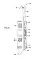
- FIG. 1depicts an illustrative, partial section view of a configurable insert 100 for use with a downhole plug, according to one or more embodiments.
- the configurable insert 100can include a body 102 having a passageway or bore 105 formed completely or at least partially therethrough.
- the body 102can have one or more threads 110 cut into, formed on, or otherwise positioned on an outer surface thereof and one or more threads 120 disposed about, cut into, or formed or otherwise positioned on an inner surface thereof.
- the configurable insert 100can further include one or more shear grooves 130 adapted to shear at a predetermined force or stress.
- the term “shear groove,”is intended to refer to any component, part, element, member, or thing that shears or is capable of shearing at a predetermined force that is less than the force required to shear the body of the plug.
- the shear groove 130can be a channel and/or indentation disposed on or formed into the inner and/or outer surface of the configurable insert 100 so that the insert 100 has a reduced wall thickness at the point of the shear groove 130 .
- the shear groove 130can be continuous about the inner or outer surface of the configurable insert 100 or the shear groove 130 can be intermittently formed thereabout using any pattern or frequency of channels and/or indentations.
- the shear groove 130is intended to separate or break when exposed to a given or predetermined force.
- the configurable insert 100is designed to break at any of the one or more shear grooves 130 disposed thereon when a predetermined axial, radial, or combination of axial and radial forces is applied to the configurable insert 100 .
- the bore 105can have a constant diameter throughout, or the diameter can vary, as depicted in FIG. 1 .
- the bore 105can include one or more larger diameter portions or areas 106 that transition to one or more smaller diameter portions or areas 107 , forming at least one seat or shoulder 125 therebetween.
- the shoulder 125can be a sloped surface between the two portions or areas 106 , 107 , as depicted in FIG. 1 .
- a second shoulder 115can be formed as a result of a transition to the larger diameter portion or area 106 from the shear groove 130 having a reduced wall thickness such that the shear groove 130 can define a diameter larger than the diameter of the larger diameter portion or area 106 .
- a third shoulder 135can be formed by the transition from the portion or area 107 to the lower end 114 of the body 102 .
- the seats or shoulders 115 , 125 , 135can be sloped surfaces, as depicted in FIG. 1 , or alternatively flat or substantially flat (not shown).
- the threads 110can facilitate connection of the configurable insert 100 to a plug, as described below in more detail. Any number of threads 110 can be used.
- the number of threads 110can range from about 2 to about 100, such as about 2 to about 50; about 3 to about 25; or about 4 to about 10.
- the number of threads 110can also range from a low of about 2, 4, or 6 to a high of about 7, 12, or 20.
- the pitch of the threads 110can range from about 0.1 mm to about 200 mm; 0.2 mm to about 150 mm; 0.3 mm to about 100 mm; or about 0.1 mm to about 50 mm.
- the pitch of the threads 110can also range from a low of about 0.1 mm, 0.2 mm, or 0.3 mm to a high of about 2 mm, 5 mm or 10 mm.
- the pitch of the threads 110can also vary along the axial length of the body 102 , for example, ranging from about 0.1 mm to about 200 mm; 0.2 mm to about 150 mm; 0.3 mm to about 100 mm; or about 0.1 mm to about 50 mm.
- the pitch of the threads 110can also vary along the axial length of the body 102 from a low of about 0.1 mm, 0.2 mm, or 0.3 mm to a high of about 2 mm, 5 mm or 10 mm.
- the threads 120are disposed on an inner surface the body 102 for threadably attaching the configurable insert 100 to another configurable insert 100 , a setting tool, another downhole tool, plug, or tubing string.
- the threads 120can be located toward, near, or at the upper end 113 . Any number of threads 120 can be used.
- the number of threads 110can range from about 2 to about 100, such as about 2 to about 50; about 3 to about 25; or about 4 to about 10.
- the number of threads 120can also range from a low of about 2, 4, or 6 to a high of about 7, 12, or 20.
- the pitch of the threads 120can range from about 0.1 mm to about 200 mm; 0.2 mm to about 150 mm; 0.3 mm to about 100 mm; or about 0.1 mm to about 50 mm.
- the pitch of the threads 120can also range from a low of about 0.1 mm, 0.2 mm, or 0.3 mm to a high of about 2 mm, 5 mm or 10 mm.
- the pitch of the threads 120can also vary along the axial length of the body 102 , for example, ranging from about 0.1 mm to about 200 mm; 0.2 mm to about 150 mm; 0.3 mm to about 100 mm; or about 0.1 mm to about 50 mm.
- the pitch of the threads 120can also vary along the axial length of the body 102 from a low of about 0.1 mm, 0.2 mm, or 0.3 mm to a high of about 2 mm, 5 mm or 10 mm.
- the first or upper end 113 of the configurable insert 100can be shaped to engage one or more tools to locate and tighten the configurable insert 100 onto the plug.
- the end 113can be, without limitation, hexagonal, slotted, notched, cross-head, square, torx, security torx, tri-wing, torq-set, spanner head, triple square, polydrive, one-way, spline drive, double hex, Bristol, Pentalobular, or other known component surface shape capable of being engaged.
- the second or lower end 114 of the configurable insert 100can include one or more grooves or channels 140 disposed or otherwise formed on an outer surface thereof.
- a sealing materialsuch as an elastomeric O-ring, can be disposed within the one or more channels 140 to provide a fluid seal between the configurable insert 100 and the plug when installed therein.
- a portion of the outer surface or outer diameter of the body 102 proximal the lower end 114 of the configurable insert 100is depicted as being tapered, the outer surface or diameter of the lower end 114 can have a constant outer diameter.
- any of the shoulders 115 , 125 , 135can serve as a seat for an impediment to block or restrict flow in one or both directions through the bore 105 .
- the term “impediment”means any plug, ball, flapper, stopper, combination thereof, or thing known in the art capable of blocking fluid flow, in one or both axial directions, through the configurable insert 100 and creating a tight fluid seal at one or more of the shoulder 115 , 125 , 135 .
- the impedimentmay or may not be threadably attached to one or more interior threads 120 of the configurable insert 100 and may be coupled to the body 102 in another suitable manner.
- FIG. 2depicts an illustrative, partial section view of the configurable insert 100 , adapted to engage a solid impediment 211 to block fluid flow in two directions, according to one or more embodiments.
- the solid impediment 211can be a cork, cap, bung, cover, top, lid, plate, or any component capable of preventing fluid flow fluid flow in all directions through the bore 105 .
- the solid impediment 211can be capable of being secured to the interior surface of the bore 105 , via the threads 120 ; however, alternatively, the impediment 211 can be retained within the bore 105 by a pin or shaft, or otherwise welded or adhered in place.
- FIG. 3depicts a top plan view of the illustrative solid impediment 211 , according to one or more embodiments.
- the solid impediment 211can include ahead or other interface 212 for engaging one or more tools to locate and tighten the solid impediment 211 onto or into the configurable insert 100 .
- the interface 212can be, without limitation, hexagonal, slotted, notched, cross-head, square, torx, security torx, tri-wing, torq-set, spanner head, triple square, polydrive, one-way, spline drive, double hex, Bristol, Pentalobular, or other known component surface shape capable of being engaged.
- FIG. 4depicts an illustrative, partial section view of the configurable insert 100 adapted to block fluid flow in one direction but allow fluid flow in the other direction, according to one or more embodiments.
- the configurable insert 100can be adapted to receive an impediment provided by a ball stop 411 and a ball 409 received in the bore 105 , as shown.
- the ball stop 411can be coupled in the bore 105 via the threads 120 , such that the ball stop 411 can be easily inserted in the field, for example. Further, the ball stop 411 can be configured to retain the ball 409 in the bore 105 between the ball stop 411 and the shoulder 125 .
- the ball 409can be shaped and sized to provide a fluid tight seal against the seat or shoulder 125 to restrict fluid movement through the bore 105 in the configurable insert 100 .
- the ball 409need not be entirely spherical, and can be provided as any size and shape suitable to seal against the seat or shoulder 125 .
- the ball stop 411 and the ball 409provide a one-way check valve.
- fluidcan generally flow from the lower end 114 of the configurable insert 100 to and out through the upper end 113 thereof; however, the bore 105 may be sealed from fluid flowing from the upper end 113 of the configurable insert 100 to the lower end 114 .
- the ball stop 411can be, for example, a plate, an annular cover, a ring, a bar, a cage, a pin, or other component capable of preventing the ball 409 from moving past the ball stop 411 in the direction towards the upper end 113 of the configurable insert 100 , while still allowing fluid movement in the direction toward the upper end 113 of the configurable insert 100 .
- the ball stop 411can be similar to the solid impediment 211 , discussed and described above with reference to FIG. 2 ; however, the ball stop 411 has at least one aperture or hole 421 formed therethrough to allow fluid flow through the ball stop 411 .
- the ball stop 411can include the tool interface 212 for locating and fastening the ball stop 411 within the configurable insert 100 .
- FIG. 5depicts a top plan view of the illustrative ball stop 411 , depicted in FIG. 4 , according to one or more embodiments.
- the configurable insert 100can be formed or made from any metal, metal alloy, and/or combinations thereof, such that the configurable insert 100 can shear, break and/or otherwise deform sufficiently to separate along the shear groove 130 at a predetermined axial, radial, or combination axial and radial force without the configurable insert 100 , the connection between the configurable insert 100 and the plug, or the plug being damaged.
- at least a portion of the configurable insert 100is made of an alloy that includes brass.
- Suitable brass compositionsinclude, but are not limited to, admiralty brass, Aich's alloy, alpha brass, alpha-beta brass, aluminum brass, arsenical brass, beta brass, cartridge brass, common brass, dezincification resistant brass, gilding metal, high brass, leaded brass, lead-free brass, low brass, manganese brass, Muntz metal, nickel brass, naval brass, Nordic gold, red brass, rich low brass, tonval brass, white brass, yellow brass, and/or combinations thereof.
- the configurable insert 100can also be formed or made from other metallic materials (such as aluminum, steel, stainless steel, copper, nickel, cast iron, galvanized or non-galvanized metals, etc.), fiberglass, wood, composite materials (such as ceramics, wood/polymer blends, cloth/polymer blends, etc.), and plastics (such as polyethylene, polypropylene, polystyrene, polyurethane, polyethylethylketone (PEEK), polytetrafluoroethylene (PTFE), polyamide resins (such as nylon 6 (N6), nylon 66 (N66)), polyester resins (such as polybutylene terephthalate (PBT), polyethylene terephthalate (PET), polyethylene isophthalate (PEI), PET/PEI copolymer) polynitrile resins (such as polyacrylonitrile (PAN), polymethacrylonitrile, acrylonitrile-styrene copolymers (AS), methacrylonitrile-st
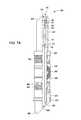
- FIG. 6depicts an illustrative, partial section view of a plug 600 configured to receive the configurable insert 100 , according to one or more embodiments.
- FIG. 7Adepicts an illustrative, partial section view of the configurable insert 100 disposed within the plug 600 , according to one or more embodiments.
- the plug 600includes one or more threads 605 disposed at or near the end thereof where the configurable insert 100 can be threadably disposed or otherwise located within the bore 655 of the plug 600 .
- At least one conical member(two are shown: 630 , 635 ), at least one slip (two are shown: 640 , 645 ), and at least one malleable element 650 can be disposed about the mandrel 610 .
- the term “disposed about”means surrounding the component, e.g., the body 610 , allowing for relative motion therebetween.
- a first section or second end of the conical members 630 , 635has a sloped surface adapted to rest underneath a complementary sloped inner surface of the slips 640 , 645 .
- the slips 640 , 645travel about the surface of the adjacent conical members 630 , 635 , thereby expanding radially outward from the mandrel 610 to engage an inner surface of a surrounding tubular or borehole.
- a second section or second end of the conical members 630 , 635can include two or more tapered pedals or wedges adapted to rest about the malleable element 650 . The wedges pivot, rotate or otherwise extend radially outward to contact an inner diameter of the surrounding tubular or borehole. Additional details of the conical members 630 , 635 are described in U.S. Pat. No. 7,762,323, the entirety of which is incorporated herein by reference to the extent consistent with the present disclosure.
- each slip 640 , 645can conform to the first end of the adjacent conical member 630 , 635 .
- An outer surface of the slips 640 , 645can include at least one outwardly-extending serration or edged tooth to engage an inner surface of a surrounding tubular, as the slips 640 , 645 move radially outward from the mandrel 610 due to the axial movement across the adjacent conical members 630 , 635 .
- the slips 640 , 645can be designed to fracture with radial stress.
- the slips 640 , 645can include at least one recessed groove 642 milled therein to fracture under stress allowing the slips 640 , 645 to expand outward and engage an inner surface of the surrounding tubular or borehole.
- the slips 640 , 645can include two or more, for example, preferably four, sloped segments separated by equally spaced recessed grooves 642 to contact the surrounding tubular or borehole.
- the malleable element 650can be disposed between the two or more conical members 630 , 635 .
- a single malleable element 650is depicted in FIG. 6 , but any number of elements 650 can be used as part of a malleable element system, as is well-known in the art.
- the malleable element 650can be constructed of any one or more malleable materials capable of expanding and sealing an annulus within the wellbore.
- the malleable element 650is preferably constructed of one or more synthetic materials capable of withstanding high temperatures and pressures, including temperatures up to 450° F., and pressure differentials up to 15,000 psi. Illustrative materials include elastomers, rubbers. TEFLON®, blends and combinations thereof.
- the malleable element(s) 650can have any number of configurations to effectively seal the annulus.
- the malleable element(s) 650can include one or more grooves, ridges, indentations, or protrusions designed to allow the malleable element(s) 650 to conform to variations in the shape of the interior of the surrounding tubular or borehole.
- At least one component, ring or other annular member 680 for receiving an axial load from a setting toolcan be disposed about the mandrel 610 and adjacent a first end of the slip 640 .
- the annular member 680can have first and second ends that are substantially flat. The first end can serve as a shoulder adapted to abut a setting tool (not shown). The second end can abut the slip 640 and transmit axial forces therethrough.
- Each end of the plug 600can be the same or different.
- Each end of the plug 600can include one or more anti-rotation features 670 , disposed thereon.
- Each anti-rotation feature 670can be screwed onto, formed thereon, or otherwise connected to or positioned about the mandrel 610 so that there is no relative motion between the anti-rotation feature 670 and the mandrel 610 .
- each anti-rotation feature 670can be screwed onto or otherwise connected to or positioned about a shoe, nose, cap or other separate component, which can be made of composite, that is screwed onto threads, or otherwise connected to or positioned about the mandrel 610 so that there is no relative motion between the anti-rotation feature 670 and the mandrel 610 .
- the anti-rotation feature 670can have various shapes and forms.
- the anti-rotation feature 670can be or can resemble a mule shoe shape (not shown), half-mule shoe shape (illustrated in FIG. 10 ), flat protrusions or flats (illustrated in FIGS. 12 and 13 ), clutches (illustrated in FIG. 11 ), or otherwise angled surfaces 625 , 685 , 690 (illustrated in FIGS. 6 , 7 A, 7 B, and 8 ).
- the anti-rotation features 670are intended to engage, connect, or otherwise contact an adjacent plug, whether above or below the adjacent plug, to prevent or otherwise retard rotation therebetween, facilitating faster drill-out or mill times.
- the angled surfaces 685 , 690 at the bottom of a first plug 200can engage the sloped surface 625 at the top of a second plug 600 in series, so that relative rotation therebetween is prevented or greatly reduced.
- a pump down collar 675can be located about a lower end of the plug 600 to facilitate delivery of the plug 600 into the wellbore.
- the pump down collar 675can be a rubber O-ring or similar sealing member to create an impediment in the wellbore during installation, so that a push surface or resistance can be created.
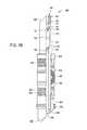
- FIGS. 7A and 7Bdepict illustrative, partial section views of the plug 600 with the configurable insert 100 disposed therein, according to one or more embodiments described.
- the configurable insert 100can be configured to receive a drop ball 701 , providing a flow impediment to control flow therein. As such, the solid impediment 212 and the ball stop 411 can be omitted.
- the drop ball 701can be received in the configurable insert 100 , for example, after deployment of the plug 600 in the wellbore, to constrain, restrict, and/or otherwise prevent fluid movement in the direction from the upper end 113 to the lower end 114 of the configurable insert 100 .
- the drop ball 701can rest on one of the shoulders 115 and/or 125 to form an essentially fluid tight seal therebetween.
- the shoulder 115 , 125 on which the drop ball 701 landscan depend on the relative sizing of the shoulder 115 , 125 and the drop ball 701 .
- the lower shoulder 125can provide a smaller-radius opening than does the upper shoulder 115 . Accordingly, a smaller drop ball 701 may pass by the upper shoulder 115 and land on the lower shoulder 125 .
- a larger drop ball 701can land on the upper shoulder 115 and thus be constrained from reaching the lower shoulder 125 .
- multiple drop balls 701can be employed and can be sized to be received on either shoulder 115 , 125 , or other shoulders that can be added to the configurable insert 100 . In general, multiple drop balls 701 are deployed in increasing size, thereby providing for each shoulder 115 , 125 (and/or others) to receive a drop ball 701 without the upper shoulders preventing access to the lower shoulders.
- the impedimentcan also include a ball 702 , disposed in the bore 655 below the configurable insert 100 .
- the ball 702can be inserted into the bore 655 prior to the installation of the configurable insert 100 , and can rest or seat against the shoulder 135 when fluid pressure is applied from the lower end of the plug 600 .
- a retaining pin or a washercan be installed into the plug 600 prior to the ball 702 to prevent the ball 702 from escaping the bore 655 .
- the configurable insertcan provide one or more shoulders 115 , 125 to receive a drop ball 701 and can provide a shoulder 135 to seal with a ball 702 disposed in the bore 655 below the configurable insert 100 . As such, fluid flow in both axial directions can be prevented: downward, by the drop ball 701 and upward, by the ball 702 .
- the plug 600can be installed in a vertical, horizontal, or deviated wellbore using any suitable setting tool (not shown) adapted to engage the plug 600 .
- a suitable setting tool or assemblyincludes a gas operated outer cylinder powered by combustion products and an adapter rod.
- the outer cylinder of the setting toolabuts an outer, upper end of the plug 600 , such as against the annular member 680 .
- the outer cylindercan also abut directly against the upper slip 640 , for example, in embodiments of the plug 600 where the annular member 680 is omitted, or where the outer cylinder fits over or otherwise avoids bearing on the annular member 680 .
- the adapter rod(not shown) is threadably connected to the mandrel 610 and/or the insert 100 .
- Suitable setting assembliesthat are commercially-available include the Owen Oil Tools wireline pressure setting assembly or a Model 10, 20 E-4, or E-5 Setting Tool available from Baker Oil Tools, for example.
- the outer cylinder (not shown) of the setting toolexerts an axial force against the outer, upper end of the plug 600 in a downward direction that is matched by the adapter rod (not shown) of the setting tool exerting an equal and opposite force from the lower end of the plug 600 in an upward direction.
- the outer cylinder of the setting assemblyexerts an axial force on the annular member 680 , which translates the force to the slips 640 , 645 and the malleable element 650 that are disposed about the mandrel 610 of the plug 600 .
- FIG. 8depicts an illustrative partial section view of the expanded or actuated plug 600 , according to one or more embodiments described.
- FIG. 9depicts an illustrative, partial section view of the expanded plug 600 depicted in FIG. 8 , according to one or more embodiments described.
- the setting toolcan be released from the plug 600 , or the insert 100 that is screwed onto the plug 600 by continuing to apply the opposing, axial forces on the mandrel 610 via the adapter rod and the outer cylinder of the setting tool.
- the opposing, axial forces applied by the outer cylinder and the adapter rodresult in a compressive load on the mandrel 610 , which is borne as internal stress once the plug 600 is actuated and secured within the casing or wellbore 800 .
- the force or stressis focused on the shear groove 130 , which will eventually shear, break, or otherwise deform at a predetermined amount, releasing the adapter rod from the plug 600 .
- the predetermined axial force sufficient to deform the shear groove 130 to release the setting toolis less than an axial force sufficient to break the plug 600 otherwise.
- the solid impediment 211 , ball stop 411 , and/or one or more of the balls, 409 , 701 , 702can be fabricated from one or more decomposable materials. Suitable decomposable materials will decompose, degrade, degenerate, or otherwise fall apart at certain wellbore conditions or environments, such as predetermined temperature, pressure, pH, and/or a combination thereof.
- fluid flow communication through the plug 600can be prevented for a predetermined period of time, e.g., until and/or if the decomposable material(s) degrade sufficiently allowing fluid flow therethrough.
- the predetermined period of timecan be sufficient to pressure test one or more hydrocarbon-bearing zones within the wellbore. In one or more embodiments, the predetermined period of time can be sufficient to workover the associated well.
- the predetermined period of timecan range from minutes to days.
- the degradable rate of the materialcan range from about 5 minutes, 40 minutes, or 4 hours to about 12 hours, 24 hours or 48 hours. Extended periods of time are also contemplated.
- the pressures at which the solid impediment 211 , the ball stop 411 , and/or one or more of the balls 409 , 701 , 702 decomposecan range from about 100 psig to about 15,000 psig.
- the pressurecan range from a low of about 100 psig, 1,000 psig, or 5,000 psig to a high about 7,500 psig, 10,000 psig, or about 15,000 psig.
- the temperatures at which the impediment 211 , ball stop 411 and/or the ball(s) 409 , 701 , 702 decomposecan range from about 100° F. to about 750° F.
- the temperature requiredcan range from a low of about 100° F., 150° F., or 200° F. to a high of about 350° F., 500° F., or 750° F.
- the decomposable materialcan be soluble in any material, such as water, polar solvents, non-polar solvents, acids, bases, mixtures thereof, or any combination thereof.
- the solventscan be time-dependent solvents.
- a time-dependent solventcan be selected based on its rate of degradation.
- suitable solventscan include one or more solvents capable of degrading the soluble components in about 30 minutes, 1 hour, or 4 hours, to about 12 hours, 24 hours, or 48 hours. Extended periods of time are also contemplated.
- the pHs at which the solid impediment 211 , ball stop 411 , and/or one or more of the balls 409 , 701 , 702 decomposecan range from about 1 to about 14.
- the pHcan range from a low of about 1, 3, or 5 to a high about 9, 11, or about 14.
- the plug 600can be drilled-out, milled or otherwise compromised.
- some remaining portion of the first, upper plugcan release from the wall of the wellbore at some point during the drill-out.
- the anti-rotation features 670 of the remaining portions of the plugs 600will engage and prevent, or at least substantially reduce, relative rotation therebetween.
- FIGS. 10-13depict schematic views of illustrative anti-rotation features that can be used with the plugs 600 to prevent or reduce rotation during drill-out. These features are not intended to be exhaustive, but merely illustrative, as there are many other configurations that are equally effective to accomplish the same results. Each end of the plug 600 can be the same or different.
- FIG. 10depicts angled surfaces or half-mule anti-rotation features
- FIG. 11depicts dog clutch type anti-rotation features
- FIGS. 12 and 13depict two types of flats and slot anti-rotation features.
- a lower end of the upper plug 1000 A and an upper end of a lower plug 1000 Bare shown within the casing 800 where the angled surfaces 685 , 690 interact with, interface with, interconnect, interlock, link with, join, jam with or within, wedge between, or otherwise communicate with a complementary angled surface 625 and/or at least a surface of the wellbore or casing 800 .
- the interaction between the lower end of the upper plug 1000 A and the upper end of the lower plug 1000 B and/or the casing 800can counteract a torque placed on the lower end of the upper plug 1000 A, and prevent or greatly reduce rotation therebetween.
- the lower end of the upper plug 1000 Acan be prevented from rotating within the wellbore or casing 800 by the interaction with upper end of the lower plug 1000 B, which is held securely within the casing 800 .
- dog clutch surfaces of the upper plug 1100 Acan interact with, interface with, interconnect, interlock, link with, join, jam with or within, wedge between, or otherwise communicate with a complementary dog clutch surface of the lower plug 1100 B and/or at least a surface of the wellbore or casing 800 .
- the interaction between the lower end of the upper plug 1100 A and the upper end of the lower plug 1100 B and/or the casing 800can counteract a torque placed on the lower end of the upper plug 1100 A, and prevent or greatly reduce rotation therebetween.
- the lower end of the upper plug 1100 Acan be prevented from rotating within the wellbore or casing 800 by the interaction with upper end of the lower plug 1100 B, which is held securely within the casing 800 .
- the flats and slot surfaces of the upper plug 1200 Acan interact with, interface with, interconnect, interlock, link with, join, jam with or within, wedge between, or otherwise communicate with complementary flats and slot surfaces of the lower plug 1200 B and/or at least a surface of the wellbore or casing 800 .
- the interaction between the lower end of the upper plug 1200 A and the upper end of the lower plug 1200 B and/or the casing 800can counteract a torque placed on the lower end of the upper plug 1200 A, and prevent or greatly reduce rotation therebetween.
- the lower end of the upper plug 1200 Acan be prevented from rotating within the wellbore or casing 800 by the interaction with upper end of the lower plug 1200 B, which is held securely within the casing 800 .
- the protruding perpendicular surfaces of the lower end of the upper plug 1200 Acan mate in only one resulting configuration with the complementary perpendicular voids of the upper end of the lower plug 1200 B.
- any further rotational force applied to the lower end of the upper plug 1200 Awill be resisted by the engagement of the lower plug 1200 B with the wellbore or casing 800 , translated through the mated surfaces of the anti-rotation feature 670 , allowing the lower end of the upper plug 1200 A to be more easily drilled-out of the wellbore.
- FIG. 13One alternative configuration of flats and slot surfaces is depicted in FIG. 13 .
- the protruding cylindrical or semi-cylindrical surfaces 1310 perpendicular to the base 1301 of the lower end of the upper plug 1300 Amate in only one resulting configuration with the complementary aperture(s) 1320 in the complementary base 1302 of the upper end of the lower plug 1300 B.
- Protruding surfaces 1310can have any geometry perpendicular to the base 1301 , as long as the complementary aperture(s) 1320 match the geometry of the protruding surfaces 1301 so that the surfaces 1301 can be threaded into the aperture(s) 1320 with sufficient material remaining in the complementary base 1302 to resist rotational force that can be applied to the lower end of the upper plug 1300 A, and thus translated to the complementary base 1302 by means of the protruding surfaces 1301 being inserted into the aperture(s) 1320 of the complementary base 1302 .
- the anti-rotation feature 670may have one or more protrusions or apertures 1330 , as depicted in FIG.
- the protrusion or aperture 1330can be of any geometry practical to further the purpose of transmitting force through the anti-rotation feature 670 .
- the orientation of the components of the anti-rotation features 670 depicted in all figuresis arbitrary. Because plugs 600 can be installed in horizontal, vertical, and deviated wellbores, either end of the plug 600 can have any anti-rotation feature 670 geometry, wherein a single plug 600 can have one end of the first geometry and one end of a second geometry.
- the anti-rotation feature 670 depicted in FIG. 10can include an alternative embodiment where the lower end of the upper plug 1000 A is manufactured with geometry resembling 1000 B and vice versa.
- Each end of each plug 600can be or include two ends of differently-shaped anti-rotation features, such as an upper end may include a half-mule anti-rotation feature 670 , and the lower end of the same plug 600 may include a dog clutch type anti-rotation feature 670 .
- two plugs 600 in seriesmay each comprise only one type of anti-rotation feature 670 each, however the interface between the two plugs 600 may result in two different anti-rotation feature geometries that can interface with, interconnect, interlock, link with, join, jam with or within, wedge between, or otherwise communicate or transmit force between the lower end of the upper plug 600 with the first geometry and the upper end of the lower plug 600 with the second geometry.
- any of the aforementioned components of the plug 600can be formed or made from any one or more non-metallic materials or one or more metallic materials (such as aluminum, steel, stainless steel, brass, copper, nickel, cast iron, galvanized or non-galvanized metals, etc.).
- Suitable non-metallic materialsinclude, but are not limited to, fiberglass, wood, composite materials (such as ceramics, wood/polymer blends, cloth/polymer blends, etc.), and plastics (such as polyethylene, polypropylene, polystyrene, polyurethane, polyethylethylketone (PEEK), polytetrafluoroethylene (PTFE), polyamide resins (such as nylon 6 (N6), nylon 66 (N66)), polyester resins (such as polybutylene terephthalate (PBT), polyethylene terephthalate (PET), polyethylene isophthalate (PEI), PET/PEI copolymer) polynitrile resins (such as polyacrylonitrile (PAN), polymethacrylonitrile, acrylonitrile-styrene copolymers (AS), methacrylonitrile-styrene copolymers, methacrylonitrile-styrene-butadiene copolymers; and
- Desirable composite materialscan include polymeric composite materials that are wound and/or reinforced by one or more fibers such as glass, carbon, or aramid, for example.
- the individual fibersare typically layered parallel to each other, and wound layer upon layer.
- Each individual layercan be wound at an angle of from about 20 degrees to about 160 degrees with respect to a common longitudinal axis, to provide additional strength and stiffness to the composite material in high temperature and/or pressure downhole conditions.
- the particular winding phasecan depend, at least in part, on the required strength and/or rigidity of the overall composite material.
- the polymeric component of the polymeric compositecan be an epoxy blend.
- the polymer component of the polymeric compositecan also be or include polyurethanes and/or phenolics, for example.
- the polymeric compositecan be a blend of two or more epoxy resins.
- the polymeric compositecan be a blend of a first epoxy resin of bisphenol A and epichlorohydrin and a second cycoaliphatic epoxy resin.
- the cycloaphatic epoxy resinis ARALDITE® liquid epoxy resin, commercially available from Ciga-Geigy Corporation of Brewster, N.Y.
- a 50:50 blend by weight of the two resinshas been found to provide the suitable stability and strength for use in high temperature and/or pressure applications.
- the 50:50 epoxy blendcan also provide suitable resistance in both high and low pH environments.
- the fiberscan be wet wound, however, a prepreg roving can also be used to form a matrix.
- the fiberscan also be wound with and/or around, spun with and/or around, molded with and/or around, or hand laid with and/or around a metal material or materials to create an epoxy impregnated metal or a metal impregnated epoxy.
- a composite of a metal with an epoxyFor example, a composite of a metal with an epoxy.
- a post cure processcan be used to achieve greater strength of the material.
- the post cure processcan be a two stage cure consisting of a gel period and a cross-linking period using an anhydride hardener, as is commonly know in the art.
- Heatcan added during the curing process to provide the appropriate reaction energy which drives the cross-linking of the matrix to completion.
- the compositemay also be exposed to ultraviolet light or a high-intensity electron beam to provide the reaction energy to cure the composite material.
- up and “down”; “upward” and “downward”; “upper” and “lower”; “upwardly” and “downwardly”; “upstream” and “downstream”; “above” and “below”; and other like terms as used hereinrefer to relative positions to one another and are not intended to denote a particular spatial orientation since the tool and methods of using same can be equally effective in either horizontal or vertical wellbore uses.
Landscapes
- Life Sciences & Earth Sciences (AREA)
- Engineering & Computer Science (AREA)
- Geology (AREA)
- Mining & Mineral Resources (AREA)
- Physics & Mathematics (AREA)
- Environmental & Geological Engineering (AREA)
- Fluid Mechanics (AREA)
- General Life Sciences & Earth Sciences (AREA)
- Geochemistry & Mineralogy (AREA)
- Earth Drilling (AREA)
- Quick-Acting Or Multi-Walled Pipe Joints (AREA)
Abstract
Description
Claims (91)
Priority Applications (3)
| Application Number | Priority Date | Filing Date | Title |
|---|---|---|---|
| US13/194,877US9062522B2 (en) | 2009-04-21 | 2011-07-29 | Configurable inserts for downhole plugs |
| US13/357,570US8307892B2 (en) | 2009-04-21 | 2012-01-24 | Configurable inserts for downhole plugs |
| US13/893,195US9181772B2 (en) | 2009-04-21 | 2013-05-13 | Decomposable impediments for downhole plugs |
Applications Claiming Priority (3)
| Application Number | Priority Date | Filing Date | Title |
|---|---|---|---|
| US21434709P | 2009-04-21 | 2009-04-21 | |
| US12/799,231US20100263876A1 (en) | 2009-04-21 | 2010-04-21 | Combination down hole tool |
| US13/194,877US9062522B2 (en) | 2009-04-21 | 2011-07-29 | Configurable inserts for downhole plugs |
Related Parent Applications (1)
| Application Number | Title | Priority Date | Filing Date |
|---|---|---|---|
| US12/799,231Continuation-In-PartUS20100263876A1 (en) | 2009-04-21 | 2010-04-21 | Combination down hole tool |
Related Child Applications (2)
| Application Number | Title | Priority Date | Filing Date |
|---|---|---|---|
| US13/357,570ContinuationUS8307892B2 (en) | 2009-04-21 | 2012-01-24 | Configurable inserts for downhole plugs |
| US13/893,195Continuation-In-PartUS9181772B2 (en) | 2009-04-21 | 2013-05-13 | Decomposable impediments for downhole plugs |
Publications (2)
| Publication Number | Publication Date |
|---|---|
| US20110290473A1 US20110290473A1 (en) | 2011-12-01 |
| US9062522B2true US9062522B2 (en) | 2015-06-23 |
Family
ID=45021118
Family Applications (2)
| Application Number | Title | Priority Date | Filing Date |
|---|---|---|---|
| US13/194,877Expired - Fee RelatedUS9062522B2 (en) | 2009-04-21 | 2011-07-29 | Configurable inserts for downhole plugs |
| US13/357,570Expired - Fee RelatedUS8307892B2 (en) | 2009-04-21 | 2012-01-24 | Configurable inserts for downhole plugs |
Family Applications After (1)
| Application Number | Title | Priority Date | Filing Date |
|---|---|---|---|
| US13/357,570Expired - Fee RelatedUS8307892B2 (en) | 2009-04-21 | 2012-01-24 | Configurable inserts for downhole plugs |
Country Status (1)
| Country | Link |
|---|---|
| US (2) | US9062522B2 (en) |
Cited By (3)
| Publication number | Priority date | Publication date | Assignee | Title |
|---|---|---|---|---|
| US11162322B2 (en) | 2018-04-05 | 2021-11-02 | Halliburton Energy Services, Inc. | Wellbore isolation device |
| US12078026B2 (en) | 2022-12-13 | 2024-09-03 | Forum Us, Inc. | Wiper plug with dissolvable core |
| US12221851B1 (en) | 2023-11-16 | 2025-02-11 | Forum Us, Inc. | Pump down wiper plug assembly |
Families Citing this family (53)
| Publication number | Priority date | Publication date | Assignee | Title |
|---|---|---|---|---|
| US8459347B2 (en)* | 2008-12-10 | 2013-06-11 | Oiltool Engineering Services, Inc. | Subterranean well ultra-short slip and packing element system |
| US8347965B2 (en)* | 2009-11-10 | 2013-01-08 | Sanjel Corporation | Apparatus and method for creating pressure pulses in a wellbore |
| US8839869B2 (en)* | 2010-03-24 | 2014-09-23 | Halliburton Energy Services, Inc. | Composite reconfigurable tool |
| USD683435S1 (en)* | 2010-09-13 | 2013-05-28 | High Performance CT Tools, L.L.C. | Plug |
| USD694281S1 (en)* | 2011-07-29 | 2013-11-26 | W. Lynn Frazier | Lower set insert with a lower ball seat for a downhole plug |
| USD694280S1 (en)* | 2011-07-29 | 2013-11-26 | W. Lynn Frazier | Configurable insert for a downhole plug |
| USD698370S1 (en)* | 2011-07-29 | 2014-01-28 | W. Lynn Frazier | Lower set caged ball insert for a downhole plug |
| US9074439B2 (en) | 2011-08-22 | 2015-07-07 | National Boss Hog Energy Services Llc | Downhole tool and method of use |
| US10036221B2 (en) | 2011-08-22 | 2018-07-31 | Downhole Technology, Llc | Downhole tool and method of use |
| US10246967B2 (en) | 2011-08-22 | 2019-04-02 | Downhole Technology, Llc | Downhole system for use in a wellbore and method for the same |
| US10316617B2 (en) | 2011-08-22 | 2019-06-11 | Downhole Technology, Llc | Downhole tool and system, and method of use |
| US9777551B2 (en) | 2011-08-22 | 2017-10-03 | Downhole Technology, Llc | Downhole system for isolating sections of a wellbore |
| US10570694B2 (en) | 2011-08-22 | 2020-02-25 | The Wellboss Company, Llc | Downhole tool and method of use |
| US20130146307A1 (en)* | 2011-12-08 | 2013-06-13 | Baker Hughes Incorporated | Treatment plug and method of anchoring a treatment plug and then removing a portion thereof |
| CA2799967A1 (en)* | 2011-12-27 | 2013-06-27 | Ncs Oilfield Services Canada Inc. | Downhole fluid treatment tool |
| US8839855B1 (en)* | 2012-02-22 | 2014-09-23 | McClinton Energy Group, LLC | Modular changeable fractionation plug |
| US9759034B2 (en) | 2012-04-20 | 2017-09-12 | Baker Hughes Incorporated | Frac plug body |
| US9534463B2 (en) | 2012-10-09 | 2017-01-03 | W. Lynn Frazier | Pump down tool |
| US20140109415A1 (en)* | 2012-10-19 | 2014-04-24 | Hantover, Inc. | Breakaway lug drive coupler of rotary knife |
| US8936078B2 (en)* | 2012-11-29 | 2015-01-20 | Halliburton Energy Services, Inc. | Shearable control line connectors and methods of use |
| US20150013965A1 (en)* | 2013-06-24 | 2015-01-15 | Blake Robin Cox | Wellbore composite plug assembly |
| MX2017000751A (en)* | 2014-08-14 | 2017-04-27 | Halliburton Energy Services Inc | DEGRADABLE WELL INSULATION DEVICES WITH VARIOUS DEGRADATION SPEEDS. |
| US10526868B2 (en) | 2014-08-14 | 2020-01-07 | Halliburton Energy Services, Inc. | Degradable wellbore isolation devices with varying fabrication methods |
| USD762737S1 (en)* | 2014-09-03 | 2016-08-02 | Peak Completion Technologies, Inc | Compact ball seat downhole plug |
| USD763324S1 (en)* | 2014-09-03 | 2016-08-09 | PeakCompletion Technologies, Inc. | Compact ball seat downhole plug |
| WO2016036371A1 (en)* | 2014-09-04 | 2016-03-10 | Halliburton Energy Services, Inc. | Wellbore isolation devices with solid sealing elements |
| WO2016160003A1 (en)* | 2015-04-01 | 2016-10-06 | Halliburton Energy Services, Inc. | Degradable expanding wellbore isolation device |
| US10233720B2 (en)* | 2015-04-06 | 2019-03-19 | Schlumberger Technology Corporation | Actuatable plug system for use with a tubing string |
| WO2016168782A1 (en) | 2015-04-17 | 2016-10-20 | Downhole Technology, Llc | Tool and system for downhole operations and methods for the same |
| US10408012B2 (en) | 2015-07-24 | 2019-09-10 | Innovex Downhole Solutions, Inc. | Downhole tool with an expandable sleeve |
| US10156119B2 (en) | 2015-07-24 | 2018-12-18 | Innovex Downhole Solutions, Inc. | Downhole tool with an expandable sleeve |
| USD783133S1 (en) | 2015-09-03 | 2017-04-04 | Peak Completion Technologies, Inc | Compact ball seat downhole plug |
| USD807991S1 (en) | 2015-09-03 | 2018-01-16 | Peak Completion Technologies Inc. | Compact ball seat downhole plug |
| US10167698B2 (en) | 2016-04-27 | 2019-01-01 | Geodynamics, Inc. | Configurable bridge plug apparatus and method |
| CA3004370A1 (en) | 2016-07-05 | 2018-01-11 | Evan Lloyd Davies | Composition of matter and use thereof |
| MX2018004706A (en) | 2016-11-17 | 2018-08-15 | Downhole Tech Llc | Downhole tool and method of use. |
| US10227842B2 (en) | 2016-12-14 | 2019-03-12 | Innovex Downhole Solutions, Inc. | Friction-lock frac plug |
| US11078739B2 (en) | 2018-04-12 | 2021-08-03 | The Wellboss Company, Llc | Downhole tool with bottom composite slip |
| US10801298B2 (en) | 2018-04-23 | 2020-10-13 | The Wellboss Company, Llc | Downhole tool with tethered ball |
| US10989016B2 (en) | 2018-08-30 | 2021-04-27 | Innovex Downhole Solutions, Inc. | Downhole tool with an expandable sleeve, grit material, and button inserts |
| CA3104539A1 (en) | 2018-09-12 | 2020-03-19 | The Wellboss Company, Llc | Setting tool assembly |
| CN111021984A (en)* | 2018-10-09 | 2020-04-17 | 中国石油天然气股份有限公司 | Horizontal well shaft control device |
| US11125039B2 (en) | 2018-11-09 | 2021-09-21 | Innovex Downhole Solutions, Inc. | Deformable downhole tool with dissolvable element and brittle protective layer |
| US11965391B2 (en) | 2018-11-30 | 2024-04-23 | Innovex Downhole Solutions, Inc. | Downhole tool with sealing ring |
| US11396787B2 (en) | 2019-02-11 | 2022-07-26 | Innovex Downhole Solutions, Inc. | Downhole tool with ball-in-place setting assembly and asymmetric sleeve |
| US11261683B2 (en) | 2019-03-01 | 2022-03-01 | Innovex Downhole Solutions, Inc. | Downhole tool with sleeve and slip |
| US11203913B2 (en) | 2019-03-15 | 2021-12-21 | Innovex Downhole Solutions, Inc. | Downhole tool and methods |
| US12146380B2 (en)* | 2019-05-10 | 2024-11-19 | G&H Diversified Manufacturing Lp | Mandrel assemblies for a plug and associated methods |
| WO2021076899A1 (en) | 2019-10-16 | 2021-04-22 | The Wellboss Company, Llc | Downhole tool and method of use |
| CA3154895A1 (en) | 2019-10-16 | 2021-04-22 | Gabriel Slup | Downhole tool and method of use |
| US11572753B2 (en) | 2020-02-18 | 2023-02-07 | Innovex Downhole Solutions, Inc. | Downhole tool with an acid pill |
| US11814857B2 (en)* | 2021-02-05 | 2023-11-14 | Jarred Reinhardt | Sand anchor utilizing compressed gas |
| US12378832B2 (en) | 2021-10-05 | 2025-08-05 | Halliburton Energy Services, Inc. | Expandable metal sealing/anchoring tool |
Citations (323)
| Publication number | Priority date | Publication date | Assignee | Title |
|---|---|---|---|---|
| US1476727A (en) | 1922-08-01 | 1923-12-11 | James S Quigg | Oil-well packer |
| USRE17217E (en) | 1929-02-19 | Casinoshoe | ||
| US2040889A (en) | 1933-05-23 | 1936-05-19 | Sullivan Machinery Co | Core drill |
| US2160228A (en)* | 1938-04-11 | 1939-05-30 | Shell Dev | Process and apparatus for cementing oil wells |
| US2223602A (en) | 1938-10-04 | 1940-12-03 | Ambrose L Cox | Sand sucker apparatus |
| US2230447A (en) | 1939-08-26 | 1941-02-04 | Bassinger Ross | Well plug |
| US2286126A (en) | 1940-07-05 | 1942-06-09 | Charles W Thornhill | Well cementing apparatus |
| US2331532A (en) | 1940-08-24 | 1943-10-12 | Bassinger Ross | Well plug |
| US2376605A (en) | 1942-01-28 | 1945-05-22 | Richard R Lawrence | Wire line safety control packer |
| US2555627A (en) | 1945-12-22 | 1951-06-05 | Baker Oil Tools Inc | Bridge plug |
| US2589506A (en)* | 1947-04-15 | 1952-03-18 | Halliburton Oil Well Cementing | Drillable packer |
| US2593520A (en) | 1945-10-11 | 1952-04-22 | Baker Oil Tools Inc | Well cementing apparatus |
| US2616502A (en) | 1948-03-15 | 1952-11-04 | Texas Co | By-pass connection for hydraulic well pumps |
| US2630865A (en) | 1949-02-25 | 1953-03-10 | Baker Oil Tools Inc | Hydraulically operated well packer |
| US2637402A (en) | 1948-11-27 | 1953-05-05 | Baker Oil Tools Inc | Pressure operated well apparatus |
| US2640546A (en) | 1949-03-11 | 1953-06-02 | Baker Oil Tools Inc | Apparatus for operating tools in well bores |
| US2671512A (en)* | 1948-07-12 | 1954-03-09 | Baker Oil Tools Inc | Well packer apparatus |
| US2695068A (en) | 1951-06-01 | 1954-11-23 | Baker Oil Tools Inc | Packing device |
| US2713910A (en) | 1950-06-19 | 1955-07-26 | Baker Oil Tools Inc | Releasable operating devices for subsurface well tools |
| US2714932A (en) | 1951-08-08 | 1955-08-09 | Lane Wells Co | Bridging plug |
| US2737242A (en) | 1952-08-19 | 1956-03-06 | Baker Oil Tools Inc | Explosion resistant well packer |
| US2756827A (en) | 1952-09-10 | 1956-07-31 | Willie W Farrar | Retrievable well packers with opposing slips |
| US2815816A (en) | 1955-06-20 | 1957-12-10 | Baker Oil Tools Inc | Automatically relieved gas pressure well apparatus |
| US2830666A (en) | 1956-07-12 | 1958-04-15 | George A Butler | Combined sealing plug and tubing hanger |
| US2833354A (en) | 1955-02-15 | 1958-05-06 | George H Sailers | Screen and set shoe assembly for wells |
| US3013612A (en) | 1957-09-13 | 1961-12-19 | Phillips Petroleum Co | Casing bottom fill device |
| US3054453A (en) | 1958-09-15 | 1962-09-18 | James W Bonner | Well packer |
| US3062296A (en) | 1960-12-01 | 1962-11-06 | Brown Oil Tools | Differential pressure fill-up shoe |
| GB914030A (en) | 1957-10-09 | 1962-12-28 | Kigass Ltd | Improvements in or relating to fuel atomisers for internal combustion engines |
| US3082824A (en) | 1959-03-20 | 1963-03-26 | Lane Wells Co | Well packing devices |
| US3094166A (en) | 1960-07-25 | 1963-06-18 | Ira J Mccullough | Power tool |
| US3160209A (en) | 1961-12-20 | 1964-12-08 | James W Bonner | Well apparatus setting tool |
| US3163225A (en) | 1961-02-15 | 1964-12-29 | Halliburton Co | Well packers |
| US3270819A (en) | 1964-03-09 | 1966-09-06 | Baker Oil Tools Inc | Apparatus for mechanically setting well tools |
| US3273588A (en) | 1966-09-20 | Flow control valve for usb in a well tubing string | ||
| US3282342A (en) | 1963-11-21 | 1966-11-01 | C C Brown | Well packer |
| US3291218A (en) | 1964-02-17 | 1966-12-13 | Schlumberger Well Surv Corp | Permanently set bridge plug |
| US3298437A (en) | 1964-08-19 | 1967-01-17 | Martin B Conrad | Actuator device for well tool |
| US3298440A (en) | 1965-10-11 | 1967-01-17 | Schlumberger Well Surv Corp | Non-retrievable bridge plug |
| US3306362A (en) | 1964-03-11 | 1967-02-28 | Schlumberger Technology Corp | Permanently set bridge plug |
| US3308895A (en) | 1964-12-16 | 1967-03-14 | Huber Corp J M | Core barrel drill |
| US3356140A (en) | 1965-07-13 | 1967-12-05 | Gearhart Owen Inc | Subsurface well bore fluid flow control apparatus |
| US3387660A (en) | 1966-07-07 | 1968-06-11 | Schlumberger Technology Corp | Cement-retaining well packer |
| US3393743A (en) | 1965-11-12 | 1968-07-23 | Mini Petrolului | Retrievable packer for wells |
| US3429375A (en) | 1966-12-02 | 1969-02-25 | Schlumberger Technology Corp | Well tool with selectively engaged anchoring means |
| US3517742A (en) | 1969-04-01 | 1970-06-30 | Dresser Ind | Well packer and packing element supporting members therefor |
| US3554280A (en) | 1969-01-21 | 1971-01-12 | Dresser Ind | Well packer and sealing elements therefor |
| US3602305A (en) | 1969-12-31 | 1971-08-31 | Schlumberger Technology Corp | Retrievable well packer |
| US3623551A (en) | 1970-01-02 | 1971-11-30 | Schlumberger Technology Corp | Anchoring apparatus for a well packer |
| US3687202A (en) | 1970-12-28 | 1972-08-29 | Otis Eng Corp | Method and apparatus for treating wells |
| US3787101A (en) | 1972-05-01 | 1974-01-22 | Robbins Co | Rock cutter assembly |
| US3818987A (en) | 1972-11-17 | 1974-06-25 | Dresser Ind | Well packer and retriever |
| US3851706A (en) | 1972-11-17 | 1974-12-03 | Dresser Ind | Well packer and retriever |
| US3860066A (en) | 1972-03-27 | 1975-01-14 | Otis Eng Co | Safety valves for wells |
| US3926253A (en) | 1974-05-28 | 1975-12-16 | John A Duke | Well conduit cementing adapter tool |
| US4035024A (en) | 1975-12-15 | 1977-07-12 | Jarva, Inc. | Hard rock trench cutting machine |
| US4049015A (en) | 1974-08-08 | 1977-09-20 | Brown Oil Tools, Inc. | Check valve assembly |
| US4134455A (en) | 1977-06-14 | 1979-01-16 | Dresser Industries, Inc. | Oilwell tubing tester with trapped valve seal |
| US4151875A (en)* | 1977-12-12 | 1979-05-01 | Halliburton Company | EZ disposal packer |
| US4185689A (en) | 1978-09-05 | 1980-01-29 | Halliburton Company | Casing bridge plug with push-out pressure equalizer valve |
| US4189183A (en) | 1977-07-23 | 1980-02-19 | Gebr. Eickhoff, Maschinenfabrik Und Eisengiesserei M.B.H. | Mining machine with cutter drums and sensing apparatus |
| US4250960A (en) | 1977-04-18 | 1981-02-17 | Weatherford/Dmc, Inc. | Chemical cutting apparatus |
| US4314608A (en) | 1980-06-12 | 1982-02-09 | Tri-State Oil Tool Industries, Inc. | Method and apparatus for well treating |
| US4381038A (en) | 1980-11-21 | 1983-04-26 | The Robbins Company | Raise bit with cutters stepped in a spiral and flywheel |
| US4391547A (en) | 1981-11-27 | 1983-07-05 | Dresser Industries, Inc. | Quick release downhole motor coupling |
| US4405017A (en) | 1981-10-02 | 1983-09-20 | Baker International Corporation | Positive locating expendable plug |
| US4432418A (en) | 1981-11-09 | 1984-02-21 | Mayland Harold E | Apparatus for releasably bridging a well |
| US4436151A (en) | 1982-06-07 | 1984-03-13 | Baker Oil Tools, Inc. | Apparatus for well cementing through a tubular member |
| US4437516A (en) | 1981-06-03 | 1984-03-20 | Baker International Corporation | Combination release mechanism for downhole well apparatus |
| US4457376A (en) | 1982-05-17 | 1984-07-03 | Baker Oil Tools, Inc. | Flapper type safety valve for subterranean wells |
| US4493374A (en) | 1983-03-24 | 1985-01-15 | Arlington Automatics, Inc. | Hydraulic setting tool |
| US4532995A (en) | 1983-08-17 | 1985-08-06 | Kaufman Harry J | Well casing float shoe or collar |
| US4548442A (en) | 1983-12-06 | 1985-10-22 | The Robbins Company | Mobile mining machine and method |
| US4554981A (en) | 1983-08-01 | 1985-11-26 | Hughes Tool Company | Tubing pressurized firing apparatus for a tubing conveyed perforating gun |
| US4566541A (en) | 1983-10-19 | 1986-01-28 | Compagnie Francaise Des Petroles | Production tubes for use in the completion of an oil well |
| US4585067A (en) | 1984-08-29 | 1986-04-29 | Camco, Incorporated | Method and apparatus for stopping well production |
| US4595052A (en) | 1983-03-15 | 1986-06-17 | Metalurgica Industrial Mecanica S.A. | Reperforable bridge plug |
| US4602654A (en) | 1985-09-04 | 1986-07-29 | Hydra-Shield Manufacturing Co. | Coupling for fire hydrant-fire hose connection |
| US4688641A (en) | 1986-07-25 | 1987-08-25 | Camco, Incorporated | Well packer with releasable head and method of releasing |
| US4708163A (en) | 1987-01-28 | 1987-11-24 | Otis Engineering Corporation | Safety valve |
| US4708202A (en) | 1984-05-17 | 1987-11-24 | The Western Company Of North America | Drillable well-fluid flow control tool |
| USD293798S (en) | 1985-01-18 | 1988-01-19 | Herbert Johnson | Tool for holding round thread dies |
| US4776410A (en) | 1986-08-04 | 1988-10-11 | Oil Patch Group Inc. | Stabilizing tool for well drilling |
| US4784226A (en) | 1987-05-22 | 1988-11-15 | Arrow Oil Tools, Inc. | Drillable bridge plug |
| US4792000A (en) | 1986-08-04 | 1988-12-20 | Oil Patch Group, Inc. | Method and apparatus for well drilling |
| US4830103A (en) | 1988-04-12 | 1989-05-16 | Dresser Industries, Inc. | Setting tool for mechanical packer |
| US4848459A (en) | 1988-04-12 | 1989-07-18 | Dresser Industries, Inc. | Apparatus for installing a liner within a well bore |
| US4893678A (en) | 1988-06-08 | 1990-01-16 | Tam International | Multiple-set downhole tool and method |
| US4898245A (en) | 1987-01-28 | 1990-02-06 | Texas Iron Works, Inc. | Retrievable well bore tubular member packer arrangement and method |
| US5020590A (en) | 1988-12-01 | 1991-06-04 | Mcleod Roderick D | Back pressure plug tool |
| US5074063A (en) | 1989-06-02 | 1991-12-24 | Pella Engineering & Reseach Corporation | Undercut trenching machine |
| US5082061A (en) | 1990-07-25 | 1992-01-21 | Otis Engineering Corporation | Rotary locking system with metal seals |
| US5095980A (en) | 1991-02-15 | 1992-03-17 | Halliburton Company | Non-rotating cementing plug with molded inserts |
| US5113940A (en) | 1990-05-02 | 1992-05-19 | Weatherford U.S., Inc. | Well apparatuses and anti-rotation device for well apparatuses |
| US5117915A (en) | 1989-08-31 | 1992-06-02 | Union Oil Company Of California | Well casing flotation device and method |
| US5154228A (en) | 1990-05-22 | 1992-10-13 | Gambertoglio Louis M | Valving system for hurricane plugs |
| US5183068A (en) | 1991-06-04 | 1993-02-02 | Coors Technical Ceramics Company | Ball and seat valve |
| US5188182A (en) | 1990-07-13 | 1993-02-23 | Otis Engineering Corporation | System containing expendible isolation valve with frangible sealing member, seat arrangement and method for use |
| US5207274A (en) | 1991-08-12 | 1993-05-04 | Halliburton Company | Apparatus and method of anchoring and releasing from a packer |
| US5209310A (en) | 1990-09-13 | 1993-05-11 | Diamant Boart Stratabit Limited | Corebarrel |
| US5216050A (en) | 1988-08-08 | 1993-06-01 | Biopak Technology, Ltd. | Blends of polyactic acid |
| US5219380A (en) | 1992-03-27 | 1993-06-15 | Vermeer Manufacturing Company | Trenching apparatus |
| US5224540A (en) | 1990-04-26 | 1993-07-06 | Halliburton Company | Downhole tool apparatus with non-metallic components and methods of drilling thereof |
| US5230390A (en) | 1992-03-06 | 1993-07-27 | Baker Hughes Incorporated | Self-contained closure mechanism for a core barrel inner tube assembly |
| US5234052A (en) | 1992-05-01 | 1993-08-10 | Davis-Lynch, Inc. | Cementing apparatus |
| US5253705A (en) | 1992-04-09 | 1993-10-19 | Otis Engineering Corporation | Hostile environment packer system |
| US5271468A (en) | 1990-04-26 | 1993-12-21 | Halliburton Company | Downhole tool apparatus with non-metallic components and methods of drilling thereof |
| US5295735A (en) | 1992-06-10 | 1994-03-22 | Cobbs David C | Rock saw |
| US5311939A (en) | 1992-07-16 | 1994-05-17 | Camco International Inc. | Multiple use well packer |
| US5316081A (en) | 1993-03-08 | 1994-05-31 | Baski Water Instruments | Flow and pressure control packer valve |
| US5318131A (en) | 1992-04-03 | 1994-06-07 | Baker Samuel F | Hydraulically actuated liner hanger arrangement and method |
| US5343954A (en) | 1992-11-03 | 1994-09-06 | Halliburton Company | Apparatus and method of anchoring and releasing from a packer |
| USD350887S (en) | 1993-02-26 | 1994-09-27 | C. M. E. Blasting and Mining Equipment Ltd. | Grinding cup |
| USD353756S (en) | 1993-03-03 | 1994-12-27 | O-Ratchet, Inc. | Socket wrench extension |
| USD355428S (en) | 1993-09-27 | 1995-02-14 | Hatcher Wayne B | Angled severing head |
| US5390737A (en) | 1990-04-26 | 1995-02-21 | Halliburton Company | Downhole tool with sliding valve |
| US5392540A (en) | 1993-06-10 | 1995-02-28 | Vermeer Manufacturing Company | Mounting apparatus for a bridge of a trenching machine |
| US5419399A (en) | 1994-05-05 | 1995-05-30 | Canadian Fracmaster Ltd. | Hydraulic disconnect |
| USRE35088E (en) | 1991-05-08 | 1995-11-14 | Trencor Jetco, Inc. | Trenching machine with laterally adjustable chain-type digging implement |
| US5484191A (en) | 1993-09-02 | 1996-01-16 | The Sollami Company | Insert for tungsten carbide tool |
| US5490339A (en) | 1994-06-02 | 1996-02-13 | Accettola; Frank J. | Trenching system for earth surface use, as on paved streets, roads, highways and the like |
| US5540279A (en) | 1995-05-16 | 1996-07-30 | Halliburton Company | Downhole tool apparatus with non-metallic packer element retaining shoes |
| US5564502A (en) | 1994-07-12 | 1996-10-15 | Halliburton Company | Well completion system with flapper control valve |
| US5593292A (en) | 1994-05-04 | 1997-01-14 | Ivey; Ray K. | Valve cage for a rod drawn positive displacement pump |
| USD377969S (en) | 1995-08-14 | 1997-02-11 | Vapor Systems Technologies, Inc. | Coaxial hose fitting |
| US5655614A (en) | 1994-12-20 | 1997-08-12 | Smith International, Inc. | Self-centering polycrystalline diamond cutting rock bit |
| US5688586A (en) | 1995-06-20 | 1997-11-18 | Kureha Kagaku Kogyo K.K. | Poly(ethylene oxalate), product formed of molded therefrom and production process of poly(ethylene oxalate) |
| US5701959A (en) | 1996-03-29 | 1997-12-30 | Halliburton Company | Downhole tool apparatus and method of limiting packer element extrusion |
| US5785135A (en) | 1996-10-03 | 1998-07-28 | Baker Hughes Incorporated | Earth-boring bit having cutter with replaceable kerf ring with contoured inserts |
| US5791825A (en) | 1996-10-04 | 1998-08-11 | Lockheed Martin Idaho Technologies Company | Device and method for producing a containment barrier underneath and around in-situ buried waste |
| US5803173A (en) | 1996-07-29 | 1998-09-08 | Baker Hughes Incorporated | Liner wiper plug apparatus and method |
| US5810083A (en) | 1996-11-25 | 1998-09-22 | Halliburton Energy Services, Inc. | Retrievable annular safety valve system |
| US5819846A (en) | 1996-10-01 | 1998-10-13 | Bolt, Jr.; Donald B. | Bridge plug |
| US5853639A (en) | 1996-04-30 | 1998-12-29 | Kureha Kagaku Kogyo K.K. | Oriented polyglycolic acid film and production process thereof |
| US5908917A (en) | 1996-04-30 | 1999-06-01 | Kureha Kagaku Kogyo K.K. | Polyglycolic acid sheet and production process thereof |
| US5961185A (en) | 1993-09-20 | 1999-10-05 | Excavation Engineering Associates, Inc. | Shielded cutterhead with small rolling disc cutters |
| USD415180S (en) | 1998-02-20 | 1999-10-12 | Wera Werk Hermann Werner Gmbh & Co. | Bit holder |
| US5984007A (en) | 1998-01-09 | 1999-11-16 | Halliburton Energy Services, Inc. | Chip resistant buttons for downhole tools having slip elements |
| US5988277A (en)* | 1996-11-21 | 1999-11-23 | Halliburton Energy Services, Inc. | Running tool for static wellhead plug |
| US6001439A (en) | 1996-05-09 | 1999-12-14 | Kureha Kagaku Kogyo K.K. | Stretch blow molded container and production process thereof |
| US6012519A (en) | 1998-02-09 | 2000-01-11 | Erc Industries, Inc. | Full bore tubing hanger system |
| US6046251A (en) | 1996-04-30 | 2000-04-04 | Kureha Kagaku Kogyo K.K. | Injection-molded product of polyglycolic acid and production process thereof |
| US6082451A (en) | 1995-04-26 | 2000-07-04 | Weatherford/Lamb, Inc. | Wellbore shoe joints and cementing systems |
| US6085446A (en) | 1997-12-09 | 2000-07-11 | Posch; Juergen | Device for excavating an elongated depression in soil |
| US6098716A (en) | 1997-07-23 | 2000-08-08 | Schlumberger Technology Corporation | Releasable connector assembly for a perforating gun and method |
| US6105694A (en) | 1998-06-29 | 2000-08-22 | Baker Hughes Incorporated | Diamond enhanced insert for rolling cutter bit |
| US6142226A (en) | 1998-09-08 | 2000-11-07 | Halliburton Energy Services, Inc. | Hydraulic setting tool |
| US6152232A (en) | 1998-09-08 | 2000-11-28 | Halliburton Energy Services, Inc. | Underbalanced well completion |
| US6167963B1 (en) | 1998-05-08 | 2001-01-02 | Baker Hughes Incorporated | Removable non-metallic bridge plug or packer |
| US6182752B1 (en) | 1998-07-14 | 2001-02-06 | Baker Hughes Incorporated | Multi-port cementing head |
| US6199636B1 (en) | 1999-02-16 | 2001-03-13 | Michael L. Harrison | Open barrel cage |
| US6220349B1 (en)* | 1999-05-13 | 2001-04-24 | Halliburton Energy Services, Inc. | Low pressure, high temperature composite bridge plug |
| US6245437B1 (en) | 1996-07-19 | 2001-06-12 | Kureha Kagaku Kogyo K.K. | Gas-barrier composite film |
| US6283148B1 (en) | 1996-12-17 | 2001-09-04 | Flowmore Systems, Inc. | Standing valve with a curved fin |
| US20010040035A1 (en) | 1998-05-02 | 2001-11-15 | Appleton Robert Patrick | Downhole apparatus |
| US6341823B1 (en) | 2000-05-22 | 2002-01-29 | The Sollami Company | Rotatable cutting tool with notched radial fins |
| US6367569B1 (en) | 2000-06-09 | 2002-04-09 | Baker Hughes Incorporated | Replaceable multiple TCI kerf ring |
| US6394180B1 (en) | 2000-07-12 | 2002-05-28 | Halliburton Energy Service,S Inc. | Frac plug with caged ball |
| WO2002070508A2 (en) | 2001-03-06 | 2002-09-12 | Kureha Kagaku Kogyo K.K. | Glycolide production process, and glycolic acid composition |
| US6457267B1 (en) | 2000-02-02 | 2002-10-01 | Roger D. Porter | Trenching and edging system |
| WO2002083661A1 (en) | 2001-04-12 | 2002-10-24 | Kureha Chemical Industry Company, Limited | Glycolide production process, and glycolic acid oligomer for glycolide production |
| US6491108B1 (en) | 2000-06-30 | 2002-12-10 | Bj Services Company | Drillable bridge plug |
| WO2003006526A1 (en) | 2001-07-10 | 2003-01-23 | Kureha Chemical Industry Company, Limited | Polyester production process and reactor apparatus |
| WO2003006525A1 (en) | 2001-07-10 | 2003-01-23 | Kureha Chemical Industry Company, Limited | Polyhydroxycarboxylic acid and its production process |
| US20030024706A1 (en) | 2000-12-14 | 2003-02-06 | Allamon Jerry P. | Downhole surge reduction method and apparatus |
| US6543963B2 (en) | 2000-03-16 | 2003-04-08 | Bruce L. Bruso | Apparatus for high-volume in situ soil remediation |
| WO2003037956A1 (en) | 2001-10-31 | 2003-05-08 | Kureha Chemical Industry Company, Limited | Crystalline polyglycolic acid, polyglycolic acid composition and processes for production of both |
| US6578638B2 (en) | 2001-08-27 | 2003-06-17 | Weatherford/Lamb, Inc. | Drillable inflatable packer & methods of use |
| US6581681B1 (en) | 2000-06-21 | 2003-06-24 | Weatherford/Lamb, Inc. | Bridge plug for use in a wellbore |
| US6604763B1 (en) | 1998-12-07 | 2003-08-12 | Shell Oil Company | Expandable connector |
| WO2003074092A1 (en) | 2002-03-04 | 2003-09-12 | Kureha Chemical Industry Company, Limited | Method of heat-treating packaged product and heat-treated packaged product |
| US6629563B2 (en) | 2001-05-15 | 2003-10-07 | Baker Hughes Incorporated | Packer releasing system |
| US20030188860A1 (en) | 2002-04-04 | 2003-10-09 | Weatherford/Lamb, Inc. | Releasing mechanism for downhole sealing tool |
| WO2003090438A1 (en) | 2002-04-16 | 2003-10-30 | Robert Walker | User-friendly itemised call record generation method |
| WO2003099562A1 (en) | 2002-05-24 | 2003-12-04 | Kureha Chemical Industry Company, Limited | Multilayer stretched product |
| US6673403B1 (en) | 1996-09-13 | 2004-01-06 | Kureha Kagaku Kogyo K.K. | Gas-barrier, multi-layer hollow container |
| US6695049B2 (en) | 2000-07-11 | 2004-02-24 | Fmc Technologies, Inc. | Valve assembly for hydrocarbon wells |
| US6708768B2 (en) | 2000-06-30 | 2004-03-23 | Bj Services Company | Drillable bridge plug |
| WO2004033527A1 (en) | 2002-10-08 | 2004-04-22 | Kureha Chemical Industry Company, Limited | Process for producing aliphatic polyester |
| US6725935B2 (en) | 2001-04-17 | 2004-04-27 | Halliburton Energy Services, Inc. | PDF valve |
| US6739398B1 (en) | 2001-05-18 | 2004-05-25 | Dril-Quip, Inc. | Liner hanger running tool and method |
| US6769491B2 (en) | 2002-06-07 | 2004-08-03 | Weatherford/Lamb, Inc. | Anchoring and sealing system for a downhole tool |
| US20040150533A1 (en) | 2003-02-04 | 2004-08-05 | Hall David R. | Downhole tool adapted for telemetry |
| US6796376B2 (en) | 2002-07-02 | 2004-09-28 | Warren L. Frazier | Composite bridge plug system |
| US6799633B2 (en) | 2002-06-19 | 2004-10-05 | Halliburton Energy Services, Inc. | Dockable direct mechanical actuator for downhole tools and method |
| US6834717B2 (en) | 2002-10-04 | 2004-12-28 | R&M Energy Systems, Inc. | Tubing rotator |
| US6851489B2 (en) | 2002-01-29 | 2005-02-08 | Cyril Hinds | Method and apparatus for drilling wells |
| US6854201B1 (en) | 2003-10-30 | 2005-02-15 | William D. Hunter | Cutting tooth for trencher chain |
| WO2005044894A1 (en) | 2003-11-05 | 2005-05-19 | Kureha Corporation | Process for producing aliphatic polyester |
| US6902006B2 (en) | 2002-10-03 | 2005-06-07 | Baker Hughes Incorporated | Lock open and control system access apparatus and method for a downhole safety valve |
| US6916939B2 (en) | 2000-08-11 | 2005-07-12 | Kureha Kagaku Kogyo K.K. | Process for the preparation of cyclic esters and method for purification of the same |
| US6918439B2 (en) | 2003-01-03 | 2005-07-19 | L. Murray Dallas | Backpressure adaptor pin and methods of use |
| US20050173126A1 (en) | 2004-02-11 | 2005-08-11 | Starr Phillip M. | Disposable downhole tool with segmented compression element and method |
| US20050175801A1 (en) | 2002-05-21 | 2005-08-11 | Kureha Chemical Industry Company, Limited | Bottle excellent in recyclability and method for recycling the bottle |
| US6938696B2 (en) | 2003-01-06 | 2005-09-06 | H W Ces International | Backpressure adapter pin and methods of use |
| US6944977B2 (en) | 2003-01-08 | 2005-09-20 | Compagnie Du Sol | Drum for an excavator that can be used in particular for the production of vertical trenches in hard or very hard soils |
| US20060001283A1 (en) | 2001-09-26 | 2006-01-05 | Stig Bakke | Arrangement in a gripper mechanism for a free pipe/rodlike end portion of a downhole tool |
| US20060011389A1 (en) | 2004-07-16 | 2006-01-19 | Booth Richard K | Downhole tool |
| US20060047088A1 (en) | 2002-10-08 | 2006-03-02 | Kureha Chemical Industry Company, Limited | High-molecular aliphatic polyester and process for producing the same |
| US7017672B2 (en) | 2003-05-02 | 2006-03-28 | Go Ii Oil Tools, Inc. | Self-set bridge plug |
| US7021389B2 (en) | 2003-02-24 | 2006-04-04 | Bj Services Company | Bi-directional ball seat system and method |
| US7040410B2 (en) | 2003-07-09 | 2006-05-09 | Hwc Energy Services, Inc. | Adapters for double-locking casing mandrel and method of using same |
| US7055632B2 (en) | 2003-10-08 | 2006-06-06 | H W C Energy Services, Inc. | Well stimulation tool and method for inserting a backpressure plug through a mandrel of the tool |
| WO2006064611A1 (en) | 2004-12-17 | 2006-06-22 | Kureha Corporation | Process for purifying hydroxycarboxylic acid, process for producing cyclic ester, and process for producing polylhydroxycaboxylic acid |
| US7069997B2 (en) | 2002-07-22 | 2006-07-04 | Corbin Coyes | Valve cage insert |
| US7107875B2 (en) | 2000-03-14 | 2006-09-19 | Weatherford/Lamb, Inc. | Methods and apparatus for connecting tubulars while drilling |
| US7124831B2 (en) | 2001-06-27 | 2006-10-24 | Weatherford/Lamb, Inc. | Resin impregnated continuous fiber plug with non-metallic element system |
| US7128091B2 (en) | 2003-09-25 | 2006-10-31 | Hydra—Shield Manufacturing, Inc. | Sexless coupling for fire hydrant-fire hose connection |
| US20060278405A1 (en) | 2005-06-14 | 2006-12-14 | Turley Rocky A | Method and apparatus for friction reduction in a downhole tool |
| US7150131B2 (en) | 2002-01-03 | 2006-12-19 | Ede Holdings, Inc. | Utility trenching and sidewalk system |
| US7168494B2 (en) | 2004-03-18 | 2007-01-30 | Halliburton Energy Services, Inc. | Dissolvable downhole tools |
| US20070051521A1 (en) | 2005-09-08 | 2007-03-08 | Eagle Downhole Solutions, Llc | Retrievable frac packer |
| US20070068670A1 (en) | 2003-02-20 | 2007-03-29 | Hamdeem Incorporated Limited | Downhole tool |
| US20070107908A1 (en) | 2005-11-16 | 2007-05-17 | Schlumberger Technology Corporation | Oilfield Elements Having Controlled Solubility and Methods of Use |
| US20070151722A1 (en) | 2005-12-30 | 2007-07-05 | Lehr Douglas J | Deformable release device for use with downhole tools |
| US20070227745A1 (en) | 2006-03-29 | 2007-10-04 | Smith International, Inc. | Secondary lock for a downhole tool |
| US7281584B2 (en) | 2001-07-05 | 2007-10-16 | Smith International, Inc. | Multi-cycle downhill apparatus |
| US20070240883A1 (en) | 2004-05-26 | 2007-10-18 | George Telfer | Downhole Tool |
| USD560109S1 (en) | 2005-11-28 | 2008-01-22 | Mobiletron Electronics Co., Ltd. | Adapter for impact rotary tool |
| US7325617B2 (en) | 2006-03-24 | 2008-02-05 | Baker Hughes Incorporated | Frac system without intervention |
| US7337847B2 (en) | 2002-10-22 | 2008-03-04 | Smith International, Inc. | Multi-cycle downhole apparatus |
| US20080060821A1 (en) | 2006-09-13 | 2008-03-13 | Halliburton Energy Services, Inc. | Packer element retaining system |
| US7350582B2 (en) | 2004-12-21 | 2008-04-01 | Weatherford/Lamb, Inc. | Wellbore tool with disintegratable components and method of controlling flow |
| US7353879B2 (en) | 2004-03-18 | 2008-04-08 | Halliburton Energy Services, Inc. | Biodegradable downhole tools |
| US7363967B2 (en) | 2004-05-03 | 2008-04-29 | Halliburton Energy Services, Inc. | Downhole tool with navigation system |
| US20080110635A1 (en) | 2006-11-14 | 2008-05-15 | Schlumberger Technology Corporation | Assembling Functional Modules to Form a Well Tool |
| US7389823B2 (en) | 2003-07-14 | 2008-06-24 | Weatherford/Lamb, Inc. | Retrievable bridge plug |
| US7428922B2 (en) | 2002-03-01 | 2008-09-30 | Halliburton Energy Services | Valve and position control using magnetorheological fluids |
| US20090044957A1 (en) | 2007-08-16 | 2009-02-19 | Robert Clayton | Fracturing plug convertible to a bridge plug |
| US7501464B2 (en) | 2005-10-31 | 2009-03-10 | Kureha Corporation | Process for producing aliphatic polyester composition |
| US20090081396A1 (en) | 2005-03-28 | 2009-03-26 | Kureha Corporation | Polyglycolic Acid Resin-Based Layered Sheet and Method of Producing the Same |
| US7527104B2 (en) | 2006-02-07 | 2009-05-05 | Halliburton Energy Services, Inc. | Selectively activated float equipment |
| US20090114401A1 (en) | 2004-10-29 | 2009-05-07 | Daniel Purkis | Plug |
| US20090126933A1 (en) | 2005-05-17 | 2009-05-21 | Specialised Petroleum Services Group Limited | Device and method for retrieving debris from a well |
| US7538178B2 (en) | 2003-10-15 | 2009-05-26 | Kureha Corporation | Process for producing aliphatic polyester |
| US7538179B2 (en) | 2004-11-04 | 2009-05-26 | Kureha Corporation | Process for producing aliphatic polyester |
| USD597110S1 (en) | 2006-09-22 | 2009-07-28 | Biotechnology Institute, I Mas D, S.L. | Ridge expander drill |
| US20090211749A1 (en) | 2008-02-25 | 2009-08-27 | Cameron International Corporation | Systems, methods, and devices for isolating portions of a wellhead from fluid pressure |
| US7600572B2 (en) | 2000-06-30 | 2009-10-13 | Bj Services Company | Drillable bridge plug |
| US7604058B2 (en) | 2003-05-19 | 2009-10-20 | Stinger Wellhead Protection, Inc. | Casing mandrel for facilitating well completion, re-completion or workover |
| US7637326B2 (en) | 2004-10-07 | 2009-12-29 | Bj Services Company, U.S.A. | Downhole safety valve apparatus and method |
| US7644767B2 (en) | 2007-01-02 | 2010-01-12 | Halliburton Energy Services, Inc. | Safety valve with flapper/flow tube friction reducer |
| US7673677B2 (en) | 2007-08-13 | 2010-03-09 | Baker Hughes Incorporated | Reusable ball seat having ball support member |
| US20100064859A1 (en) | 2008-09-18 | 2010-03-18 | Stephens John F | Fastener Driver |
| USD612875S1 (en) | 2008-04-22 | 2010-03-30 | C4 Carbides Limited | Cutter with pilot tip |
| US7690436B2 (en) | 2007-05-01 | 2010-04-06 | Weatherford/Lamb Inc. | Pressure isolation plug for horizontal wellbore and associated methods |
| US20100084146A1 (en) | 2008-10-08 | 2010-04-08 | Smith International, Inc. | Ball seat sub |
| US20100093948A1 (en) | 2007-01-22 | 2010-04-15 | Kureha Corporation | Aromatic polyester resin moldings and process for production thereof |
| US20100101807A1 (en) | 2008-10-27 | 2010-04-29 | Donald Roy Greenlee | Downhole apparatus with packer cup and slip |
| US7713464B2 (en) | 2001-11-01 | 2010-05-11 | Kureha Corporation | Multilayer container of polyglycolic acid and polyester and blow molding production process |
| US7728100B2 (en) | 2005-09-21 | 2010-06-01 | Kureha Corporation | Process for producing polyglycolic acid resin composition |
| US20100132960A1 (en) | 2004-02-27 | 2010-06-03 | Smith International, Inc. | Drillable bridge plug for high pressure and high temperature environments |
| US7735549B1 (en) | 2007-05-03 | 2010-06-15 | Itt Manufacturing Enterprises, Inc. | Drillable down hole tool |
| US20100155050A1 (en) | 2008-12-23 | 2010-06-24 | Frazier W Lynn | Down hole tool |
| USD618715S1 (en) | 2009-12-04 | 2010-06-29 | Ellison Educational Equipment, Inc. | Blade holder for an electronic media cutter |
| US20100184891A1 (en) | 2007-09-12 | 2010-07-22 | Kureha Corporation | Low melt viscosity polyglycolic acid, production process thereof, and use of low melt viscosity polyglycolic acid |
| US7775286B2 (en) | 2008-08-06 | 2010-08-17 | Baker Hughes Incorporated | Convertible downhole devices and method of performing downhole operations using convertible downhole devices |
| US7777529B1 (en) | 2005-11-07 | 2010-08-17 | Altera Corporation | Leakage compensation in dynamic flip-flop |
| US20100215858A1 (en) | 2004-09-08 | 2010-08-26 | Kureha Corporation | Process for producing a polyglycolic acid resin-based multilayer sheet |
| US7785682B2 (en) | 2004-06-25 | 2010-08-31 | Kureha Corporation | Multilayer sheet made of polyglycolic acid resin |
| US7784550B2 (en) | 2006-11-21 | 2010-08-31 | Swelltec Limited | Downhole apparatus with a swellable connector |
| US20100252252A1 (en) | 2009-04-02 | 2010-10-07 | Enhanced Oilfield Technologies, Llc | Hydraulic setting assembly |
| US7812181B2 (en) | 2006-06-19 | 2010-10-12 | Kureha Corporation | Process for producing glycolide and glycolic acid oligomer for production of glycolide |
| US7810558B2 (en) | 2004-02-27 | 2010-10-12 | Smith International, Inc. | Drillable bridge plug |
| US20100263876A1 (en) | 2009-04-21 | 2010-10-21 | Frazier W Lynn | Combination down hole tool |
| US20100276159A1 (en) | 2010-07-14 | 2010-11-04 | Tejas Completion Solutions | Non-Damaging Slips and Drillable Bridge Plug |
| WO2010127457A1 (en) | 2009-05-07 | 2010-11-11 | Packers Plus Energy Services Inc. | Sliding sleeve sub and method and apparatus for wellbore fluid treatment |
| US20100286317A1 (en) | 2007-12-27 | 2010-11-11 | Kureha Corporation | Polypropylene Resin Composition, Formed Product Composed of the Resin Composition, and Production Process of the Formed Product |
| US20100288503A1 (en) | 2009-02-25 | 2010-11-18 | Cuiper Glen H | Subsea connector |
| USD629820S1 (en) | 2010-05-11 | 2010-12-28 | Mathys Marion Van Ryswyk | Piercing cap drive socket |
| US7866396B2 (en) | 2006-06-06 | 2011-01-11 | Schlumberger Technology Corporation | Systems and methods for completing a multiple zone well |
| US20110008578A1 (en) | 2008-03-26 | 2011-01-13 | Kureha Corporation | Method for producing polymer molded body |
| US20110005779A1 (en) | 2009-07-09 | 2011-01-13 | Weatherford/Lamb, Inc. | Composite downhole tool with reduced slip volume |
| US7878242B2 (en) | 2008-06-04 | 2011-02-01 | Weatherford/Lamb, Inc. | Interface for deploying wireline tools with non-electric string |
| US20110027590A1 (en) | 2008-02-28 | 2011-02-03 | Kureha Corporation | Sequentially Biaxially-Oriented Polyglycolic Acid Film, Production Process Thereof and Multi-Layer Film |
| US7886830B2 (en) | 2004-10-07 | 2011-02-15 | Bj Services Company, U.S.A. | Downhole safety valve apparatus and method |
| US20110036564A1 (en) | 2009-08-11 | 2011-02-17 | Weatherford/Lamb, Inc. | Retrievable Bridge Plug |
| US7900696B1 (en) | 2008-08-15 | 2011-03-08 | Itt Manufacturing Enterprises, Inc. | Downhole tool with exposable and openable flow-back vents |
| US20110061856A1 (en) | 2009-09-11 | 2011-03-17 | Baker Hughes Incorporated | Tubular seat and tubular actuating system |
| US7909108B2 (en) | 2009-04-03 | 2011-03-22 | Halliburton Energy Services Inc. | System and method for servicing a wellbore |
| US7909109B2 (en) | 2002-12-06 | 2011-03-22 | Tesco Corporation | Anchoring device for a wellbore tool |
| US7918278B2 (en) | 2007-05-16 | 2011-04-05 | Gulfstream Services, Inc. | Method and apparatus for dropping a pump down plug or ball |
| USD635429S1 (en) | 2009-09-18 | 2011-04-05 | Guhring Ohg | Fastenings, supports or assemblies |
| US7921925B2 (en) | 1999-12-22 | 2011-04-12 | Weatherford/Lamb, Inc. | Method and apparatus for expanding and separating tubulars in a wellbore |
| US7926571B2 (en) | 2005-03-15 | 2011-04-19 | Raymond A. Hofman | Cemented open hole selective fracing system |
| US20110088915A1 (en) | 2009-10-21 | 2011-04-21 | Milorad Stanojcic | Bottom Hole Assembly for Subterranean Operations |
| US20110104437A1 (en) | 2008-06-16 | 2011-05-05 | Toray Industries, Inc. | Vapor deposition film |
| US20110103915A1 (en) | 2007-08-06 | 2011-05-05 | Eyeego, Llc | Screw With Breakaway and Methods of Using The Same |
| US7976919B2 (en) | 2005-04-01 | 2011-07-12 | Kureha Corporation | Multilayer blow molded container and production process thereof |
| US20110168404A1 (en) | 2008-07-16 | 2011-07-14 | Specialised Petroleum Services Group Limited | Downhole tool |
| US20110190456A1 (en) | 2008-09-30 | 2011-08-04 | Kureha Corporation | Polyglycolic acid resin composition and molded article therefrom |
| US7998385B2 (en) | 2003-10-01 | 2011-08-16 | Kureha Corporation | Method for producing multilayer stretch-molded article |
| US20110198082A1 (en) | 2010-02-18 | 2011-08-18 | Ncs Oilfield Services Canada Inc. | Downhole tool assembly with debris relief, and method for using same |
| US8003721B2 (en) | 2006-07-07 | 2011-08-23 | Kureha Corporation | Aliphatic polyester composition and method for producing the same |
| US20110240295A1 (en) | 2010-03-31 | 2011-10-06 | Porter Jesse C | Convertible downhole isolation plug |
| US8039548B2 (en) | 2006-08-02 | 2011-10-18 | Kureha Corporation | Method for purifying hydroxycarboxylic acid, method for producing cyclic ester, and method for producing polyhydroxycarboxylic acid |
| US20110259610A1 (en) | 2010-04-23 | 2011-10-27 | Smith International, Inc. | High pressure and high temperature ball seat |
| US20110263875A1 (en) | 2008-12-26 | 2011-10-27 | Kureha Corporation | Production Process of Glycolide |
| US8079413B2 (en) | 2008-12-23 | 2011-12-20 | W. Lynn Frazier | Bottom set downhole plug |
| US8119699B2 (en) | 2003-11-21 | 2012-02-21 | Kureha Corporation | Method of recycling laminated molding |
| US20120046414A1 (en) | 2009-04-20 | 2012-02-23 | Kureha Corporation | Method for producing solid polyglycolic acid-based resin composition |
| US8133955B2 (en) | 2007-01-22 | 2012-03-13 | Kureha Corporation | Aromatic polyester resin composition and process for production thereof |
| US20120086147A1 (en) | 2009-06-08 | 2012-04-12 | Kureha Corporation | Method for producing polyglycolic acid fiber |
| USD657807S1 (en) | 2011-07-29 | 2012-04-17 | Frazier W Lynn | Configurable insert for a downhole tool |
| US8163866B2 (en) | 2007-01-22 | 2012-04-24 | Kureha Corporation | Aromatic polyester resin composition |
| US20120125642A1 (en) | 2010-11-23 | 2012-05-24 | Chenault Louis W | Convertible multi-function downhole isolation tool and related methods |
| US20120130024A1 (en) | 2009-08-06 | 2012-05-24 | Kureha Corporation | Polyglycolic acid-based fibers and method for producing same |
| US20120156473A1 (en) | 2009-08-31 | 2012-06-21 | Kureha Corporation | Laminate and stretched laminate using the same |
| US8230925B2 (en) | 2005-06-20 | 2012-07-31 | Schlumberger Technology Corporation | Degradable fiber systems for stimulation |
| US20120193835A1 (en) | 2009-09-16 | 2012-08-02 | Kureha Corporation | Method for producing laminate |
| US8267177B1 (en) | 2008-08-15 | 2012-09-18 | Exelis Inc. | Means for creating field configurable bridge, fracture or soluble insert plugs |
| US8293826B2 (en) | 2005-03-08 | 2012-10-23 | Kureha Corporation | Aliphatic polyester resin composition |
| US20120270048A1 (en) | 2011-04-22 | 2012-10-25 | Kureha Corporation | Biodegradable aliphatic polyester particles and production process thereof |
| US8304500B2 (en) | 2005-10-28 | 2012-11-06 | Kureha Corporation | Polyglycolic acid resin particle composition and process for production thereof |
| US20120289713A1 (en) | 2010-01-19 | 2012-11-15 | Kureha Corporation | Method for producing glycolide |
| US8318837B2 (en) | 2005-11-24 | 2012-11-27 | Kureha Corporation | Method for controlling water resistance of polyglycolic acid resin |
| US8362158B2 (en) | 2005-12-02 | 2013-01-29 | Kureha Corporation | Polyglycolic acid resin composition |
| US8404868B2 (en) | 2007-02-20 | 2013-03-26 | Kureha Corporation | Method for purification of cyclic ester |
| US20130079450A1 (en) | 2010-06-04 | 2013-03-28 | Kureha Corporation | Resin Composition Containing Polyglycolic Acid Improved in Water Resistance |
| US20130081813A1 (en) | 2011-10-04 | 2013-04-04 | Feng Liang | Methods of Fluid Loss Control, Diversion, and Sealing Using Deformable Particulates |
| US20130081801A1 (en) | 2011-10-04 | 2013-04-04 | Feng Liang | Methods for Improving Coatings on Downhole Tools |
| US20130087061A1 (en) | 2009-10-22 | 2013-04-11 | Schlumberger Technology Corporation | Dissolvable material application in perforating |
| US8424610B2 (en) | 2010-03-05 | 2013-04-23 | Baker Hughes Incorporated | Flow control arrangement and method |
Family Cites Families (1)
| Publication number | Priority date | Publication date | Assignee | Title |
|---|---|---|---|---|
| US7775291B2 (en) | 2008-05-29 | 2010-08-17 | Weatherford/Lamb, Inc. | Retrievable surface controlled subsurface safety valve |
- 2011
- 2011-07-29USUS13/194,877patent/US9062522B2/ennot_activeExpired - Fee Related
- 2012
- 2012-01-24USUS13/357,570patent/US8307892B2/ennot_activeExpired - Fee Related
Patent Citations (349)
| Publication number | Priority date | Publication date | Assignee | Title |
|---|---|---|---|---|
| US3273588A (en) | 1966-09-20 | Flow control valve for usb in a well tubing string | ||
| USRE17217E (en) | 1929-02-19 | Casinoshoe | ||
| US1476727A (en) | 1922-08-01 | 1923-12-11 | James S Quigg | Oil-well packer |
| US2040889A (en) | 1933-05-23 | 1936-05-19 | Sullivan Machinery Co | Core drill |
| US2160228A (en)* | 1938-04-11 | 1939-05-30 | Shell Dev | Process and apparatus for cementing oil wells |
| US2223602A (en) | 1938-10-04 | 1940-12-03 | Ambrose L Cox | Sand sucker apparatus |
| US2230447A (en) | 1939-08-26 | 1941-02-04 | Bassinger Ross | Well plug |
| US2286126A (en) | 1940-07-05 | 1942-06-09 | Charles W Thornhill | Well cementing apparatus |
| US2331532A (en) | 1940-08-24 | 1943-10-12 | Bassinger Ross | Well plug |
| US2376605A (en) | 1942-01-28 | 1945-05-22 | Richard R Lawrence | Wire line safety control packer |
| US2593520A (en) | 1945-10-11 | 1952-04-22 | Baker Oil Tools Inc | Well cementing apparatus |
| US2555627A (en) | 1945-12-22 | 1951-06-05 | Baker Oil Tools Inc | Bridge plug |
| US2589506A (en)* | 1947-04-15 | 1952-03-18 | Halliburton Oil Well Cementing | Drillable packer |
| US2616502A (en) | 1948-03-15 | 1952-11-04 | Texas Co | By-pass connection for hydraulic well pumps |
| US2671512A (en)* | 1948-07-12 | 1954-03-09 | Baker Oil Tools Inc | Well packer apparatus |
| US2637402A (en) | 1948-11-27 | 1953-05-05 | Baker Oil Tools Inc | Pressure operated well apparatus |
| US2630865A (en) | 1949-02-25 | 1953-03-10 | Baker Oil Tools Inc | Hydraulically operated well packer |
| US2640546A (en) | 1949-03-11 | 1953-06-02 | Baker Oil Tools Inc | Apparatus for operating tools in well bores |
| US2713910A (en) | 1950-06-19 | 1955-07-26 | Baker Oil Tools Inc | Releasable operating devices for subsurface well tools |
| US2695068A (en) | 1951-06-01 | 1954-11-23 | Baker Oil Tools Inc | Packing device |
| US2714932A (en) | 1951-08-08 | 1955-08-09 | Lane Wells Co | Bridging plug |
| US2737242A (en) | 1952-08-19 | 1956-03-06 | Baker Oil Tools Inc | Explosion resistant well packer |
| US2756827A (en) | 1952-09-10 | 1956-07-31 | Willie W Farrar | Retrievable well packers with opposing slips |
| US2833354A (en) | 1955-02-15 | 1958-05-06 | George H Sailers | Screen and set shoe assembly for wells |
| US2815816A (en) | 1955-06-20 | 1957-12-10 | Baker Oil Tools Inc | Automatically relieved gas pressure well apparatus |
| US2830666A (en) | 1956-07-12 | 1958-04-15 | George A Butler | Combined sealing plug and tubing hanger |
| US3013612A (en) | 1957-09-13 | 1961-12-19 | Phillips Petroleum Co | Casing bottom fill device |
| GB914030A (en) | 1957-10-09 | 1962-12-28 | Kigass Ltd | Improvements in or relating to fuel atomisers for internal combustion engines |
| US3054453A (en) | 1958-09-15 | 1962-09-18 | James W Bonner | Well packer |
| US3082824A (en) | 1959-03-20 | 1963-03-26 | Lane Wells Co | Well packing devices |
| US3094166A (en) | 1960-07-25 | 1963-06-18 | Ira J Mccullough | Power tool |
| US3062296A (en) | 1960-12-01 | 1962-11-06 | Brown Oil Tools | Differential pressure fill-up shoe |
| US3163225A (en) | 1961-02-15 | 1964-12-29 | Halliburton Co | Well packers |
| US3160209A (en) | 1961-12-20 | 1964-12-08 | James W Bonner | Well apparatus setting tool |
| US3282342A (en) | 1963-11-21 | 1966-11-01 | C C Brown | Well packer |
| US3291218A (en) | 1964-02-17 | 1966-12-13 | Schlumberger Well Surv Corp | Permanently set bridge plug |
| US3270819A (en) | 1964-03-09 | 1966-09-06 | Baker Oil Tools Inc | Apparatus for mechanically setting well tools |
| US3306362A (en) | 1964-03-11 | 1967-02-28 | Schlumberger Technology Corp | Permanently set bridge plug |
| US3298437A (en) | 1964-08-19 | 1967-01-17 | Martin B Conrad | Actuator device for well tool |
| US3308895A (en) | 1964-12-16 | 1967-03-14 | Huber Corp J M | Core barrel drill |
| US3356140A (en) | 1965-07-13 | 1967-12-05 | Gearhart Owen Inc | Subsurface well bore fluid flow control apparatus |
| US3298440A (en) | 1965-10-11 | 1967-01-17 | Schlumberger Well Surv Corp | Non-retrievable bridge plug |
| US3393743A (en) | 1965-11-12 | 1968-07-23 | Mini Petrolului | Retrievable packer for wells |
| US3387660A (en) | 1966-07-07 | 1968-06-11 | Schlumberger Technology Corp | Cement-retaining well packer |
| US3429375A (en) | 1966-12-02 | 1969-02-25 | Schlumberger Technology Corp | Well tool with selectively engaged anchoring means |
| US3554280A (en) | 1969-01-21 | 1971-01-12 | Dresser Ind | Well packer and sealing elements therefor |
| US3517742A (en) | 1969-04-01 | 1970-06-30 | Dresser Ind | Well packer and packing element supporting members therefor |
| US3602305A (en) | 1969-12-31 | 1971-08-31 | Schlumberger Technology Corp | Retrievable well packer |
| US3623551A (en) | 1970-01-02 | 1971-11-30 | Schlumberger Technology Corp | Anchoring apparatus for a well packer |
| US3687202A (en) | 1970-12-28 | 1972-08-29 | Otis Eng Corp | Method and apparatus for treating wells |
| US3860066A (en) | 1972-03-27 | 1975-01-14 | Otis Eng Co | Safety valves for wells |
| US3787101A (en) | 1972-05-01 | 1974-01-22 | Robbins Co | Rock cutter assembly |
| US3851706A (en) | 1972-11-17 | 1974-12-03 | Dresser Ind | Well packer and retriever |
| US3818987A (en) | 1972-11-17 | 1974-06-25 | Dresser Ind | Well packer and retriever |
| US3926253A (en) | 1974-05-28 | 1975-12-16 | John A Duke | Well conduit cementing adapter tool |
| US4049015A (en) | 1974-08-08 | 1977-09-20 | Brown Oil Tools, Inc. | Check valve assembly |
| US4035024A (en) | 1975-12-15 | 1977-07-12 | Jarva, Inc. | Hard rock trench cutting machine |
| US4250960A (en) | 1977-04-18 | 1981-02-17 | Weatherford/Dmc, Inc. | Chemical cutting apparatus |
| US4134455A (en) | 1977-06-14 | 1979-01-16 | Dresser Industries, Inc. | Oilwell tubing tester with trapped valve seal |
| US4189183A (en) | 1977-07-23 | 1980-02-19 | Gebr. Eickhoff, Maschinenfabrik Und Eisengiesserei M.B.H. | Mining machine with cutter drums and sensing apparatus |
| US4151875A (en)* | 1977-12-12 | 1979-05-01 | Halliburton Company | EZ disposal packer |
| US4185689A (en) | 1978-09-05 | 1980-01-29 | Halliburton Company | Casing bridge plug with push-out pressure equalizer valve |
| US4314608A (en) | 1980-06-12 | 1982-02-09 | Tri-State Oil Tool Industries, Inc. | Method and apparatus for well treating |
| US4381038A (en) | 1980-11-21 | 1983-04-26 | The Robbins Company | Raise bit with cutters stepped in a spiral and flywheel |
| US4437516A (en) | 1981-06-03 | 1984-03-20 | Baker International Corporation | Combination release mechanism for downhole well apparatus |
| US4405017A (en) | 1981-10-02 | 1983-09-20 | Baker International Corporation | Positive locating expendable plug |
| US4432418A (en) | 1981-11-09 | 1984-02-21 | Mayland Harold E | Apparatus for releasably bridging a well |
| US4391547A (en) | 1981-11-27 | 1983-07-05 | Dresser Industries, Inc. | Quick release downhole motor coupling |
| US4457376A (en) | 1982-05-17 | 1984-07-03 | Baker Oil Tools, Inc. | Flapper type safety valve for subterranean wells |
| US4436151A (en) | 1982-06-07 | 1984-03-13 | Baker Oil Tools, Inc. | Apparatus for well cementing through a tubular member |
| US4595052A (en) | 1983-03-15 | 1986-06-17 | Metalurgica Industrial Mecanica S.A. | Reperforable bridge plug |
| US4493374A (en) | 1983-03-24 | 1985-01-15 | Arlington Automatics, Inc. | Hydraulic setting tool |
| US4554981A (en) | 1983-08-01 | 1985-11-26 | Hughes Tool Company | Tubing pressurized firing apparatus for a tubing conveyed perforating gun |
| US4532995A (en) | 1983-08-17 | 1985-08-06 | Kaufman Harry J | Well casing float shoe or collar |
| US4566541A (en) | 1983-10-19 | 1986-01-28 | Compagnie Francaise Des Petroles | Production tubes for use in the completion of an oil well |
| US4548442A (en) | 1983-12-06 | 1985-10-22 | The Robbins Company | Mobile mining machine and method |
| US4708202A (en) | 1984-05-17 | 1987-11-24 | The Western Company Of North America | Drillable well-fluid flow control tool |
| US4585067A (en) | 1984-08-29 | 1986-04-29 | Camco, Incorporated | Method and apparatus for stopping well production |
| USD293798S (en) | 1985-01-18 | 1988-01-19 | Herbert Johnson | Tool for holding round thread dies |
| US4602654A (en) | 1985-09-04 | 1986-07-29 | Hydra-Shield Manufacturing Co. | Coupling for fire hydrant-fire hose connection |
| US4688641A (en) | 1986-07-25 | 1987-08-25 | Camco, Incorporated | Well packer with releasable head and method of releasing |
| US4776410A (en) | 1986-08-04 | 1988-10-11 | Oil Patch Group Inc. | Stabilizing tool for well drilling |
| US4792000A (en) | 1986-08-04 | 1988-12-20 | Oil Patch Group, Inc. | Method and apparatus for well drilling |
| US4708163A (en) | 1987-01-28 | 1987-11-24 | Otis Engineering Corporation | Safety valve |
| US4898245A (en) | 1987-01-28 | 1990-02-06 | Texas Iron Works, Inc. | Retrievable well bore tubular member packer arrangement and method |
| US4784226A (en) | 1987-05-22 | 1988-11-15 | Arrow Oil Tools, Inc. | Drillable bridge plug |
| US4830103A (en) | 1988-04-12 | 1989-05-16 | Dresser Industries, Inc. | Setting tool for mechanical packer |
| US4848459A (en) | 1988-04-12 | 1989-07-18 | Dresser Industries, Inc. | Apparatus for installing a liner within a well bore |
| US4893678A (en) | 1988-06-08 | 1990-01-16 | Tam International | Multiple-set downhole tool and method |
| US5216050A (en) | 1988-08-08 | 1993-06-01 | Biopak Technology, Ltd. | Blends of polyactic acid |
| US5020590A (en) | 1988-12-01 | 1991-06-04 | Mcleod Roderick D | Back pressure plug tool |
| US5074063A (en) | 1989-06-02 | 1991-12-24 | Pella Engineering & Reseach Corporation | Undercut trenching machine |
| US5117915A (en) | 1989-08-31 | 1992-06-02 | Union Oil Company Of California | Well casing flotation device and method |
| US5390737A (en) | 1990-04-26 | 1995-02-21 | Halliburton Company | Downhole tool with sliding valve |
| US5271468A (en) | 1990-04-26 | 1993-12-21 | Halliburton Company | Downhole tool apparatus with non-metallic components and methods of drilling thereof |
| US5224540A (en) | 1990-04-26 | 1993-07-06 | Halliburton Company | Downhole tool apparatus with non-metallic components and methods of drilling thereof |
| US5113940A (en) | 1990-05-02 | 1992-05-19 | Weatherford U.S., Inc. | Well apparatuses and anti-rotation device for well apparatuses |
| US5154228A (en) | 1990-05-22 | 1992-10-13 | Gambertoglio Louis M | Valving system for hurricane plugs |
| US5188182A (en) | 1990-07-13 | 1993-02-23 | Otis Engineering Corporation | System containing expendible isolation valve with frangible sealing member, seat arrangement and method for use |
| US5082061A (en) | 1990-07-25 | 1992-01-21 | Otis Engineering Corporation | Rotary locking system with metal seals |
| US5209310A (en) | 1990-09-13 | 1993-05-11 | Diamant Boart Stratabit Limited | Corebarrel |
| US5095980A (en) | 1991-02-15 | 1992-03-17 | Halliburton Company | Non-rotating cementing plug with molded inserts |
| USRE35088E (en) | 1991-05-08 | 1995-11-14 | Trencor Jetco, Inc. | Trenching machine with laterally adjustable chain-type digging implement |
| US5183068A (en) | 1991-06-04 | 1993-02-02 | Coors Technical Ceramics Company | Ball and seat valve |
| US5207274A (en) | 1991-08-12 | 1993-05-04 | Halliburton Company | Apparatus and method of anchoring and releasing from a packer |
| US5230390A (en) | 1992-03-06 | 1993-07-27 | Baker Hughes Incorporated | Self-contained closure mechanism for a core barrel inner tube assembly |
| US5219380A (en) | 1992-03-27 | 1993-06-15 | Vermeer Manufacturing Company | Trenching apparatus |
| US5318131A (en) | 1992-04-03 | 1994-06-07 | Baker Samuel F | Hydraulically actuated liner hanger arrangement and method |
| US5253705A (en) | 1992-04-09 | 1993-10-19 | Otis Engineering Corporation | Hostile environment packer system |
| US5234052A (en) | 1992-05-01 | 1993-08-10 | Davis-Lynch, Inc. | Cementing apparatus |
| US5295735A (en) | 1992-06-10 | 1994-03-22 | Cobbs David C | Rock saw |
| US5311939A (en) | 1992-07-16 | 1994-05-17 | Camco International Inc. | Multiple use well packer |
| US5343954A (en) | 1992-11-03 | 1994-09-06 | Halliburton Company | Apparatus and method of anchoring and releasing from a packer |
| USD350887S (en) | 1993-02-26 | 1994-09-27 | C. M. E. Blasting and Mining Equipment Ltd. | Grinding cup |
| USD353756S (en) | 1993-03-03 | 1994-12-27 | O-Ratchet, Inc. | Socket wrench extension |
| US5316081A (en) | 1993-03-08 | 1994-05-31 | Baski Water Instruments | Flow and pressure control packer valve |
| US5392540A (en) | 1993-06-10 | 1995-02-28 | Vermeer Manufacturing Company | Mounting apparatus for a bridge of a trenching machine |
| US5484191A (en) | 1993-09-02 | 1996-01-16 | The Sollami Company | Insert for tungsten carbide tool |
| US5961185A (en) | 1993-09-20 | 1999-10-05 | Excavation Engineering Associates, Inc. | Shielded cutterhead with small rolling disc cutters |
| USD355428S (en) | 1993-09-27 | 1995-02-14 | Hatcher Wayne B | Angled severing head |
| US5593292A (en) | 1994-05-04 | 1997-01-14 | Ivey; Ray K. | Valve cage for a rod drawn positive displacement pump |
| US5419399A (en) | 1994-05-05 | 1995-05-30 | Canadian Fracmaster Ltd. | Hydraulic disconnect |
| US5490339A (en) | 1994-06-02 | 1996-02-13 | Accettola; Frank J. | Trenching system for earth surface use, as on paved streets, roads, highways and the like |
| US5564502A (en) | 1994-07-12 | 1996-10-15 | Halliburton Company | Well completion system with flapper control valve |
| US5655614A (en) | 1994-12-20 | 1997-08-12 | Smith International, Inc. | Self-centering polycrystalline diamond cutting rock bit |
| US6082451A (en) | 1995-04-26 | 2000-07-04 | Weatherford/Lamb, Inc. | Wellbore shoe joints and cementing systems |
| US5540279A (en) | 1995-05-16 | 1996-07-30 | Halliburton Company | Downhole tool apparatus with non-metallic packer element retaining shoes |
| US5688586A (en) | 1995-06-20 | 1997-11-18 | Kureha Kagaku Kogyo K.K. | Poly(ethylene oxalate), product formed of molded therefrom and production process of poly(ethylene oxalate) |
| USD377969S (en) | 1995-08-14 | 1997-02-11 | Vapor Systems Technologies, Inc. | Coaxial hose fitting |
| US5701959A (en) | 1996-03-29 | 1997-12-30 | Halliburton Company | Downhole tool apparatus and method of limiting packer element extrusion |
| US6046251A (en) | 1996-04-30 | 2000-04-04 | Kureha Kagaku Kogyo K.K. | Injection-molded product of polyglycolic acid and production process thereof |
| US6183679B1 (en) | 1996-04-30 | 2001-02-06 | Kureha Kagaku Kogyo, K.K. | Production process for injection-molded product of polyglycolic acid |
| US5853639A (en) | 1996-04-30 | 1998-12-29 | Kureha Kagaku Kogyo K.K. | Oriented polyglycolic acid film and production process thereof |
| US5908917A (en) | 1996-04-30 | 1999-06-01 | Kureha Kagaku Kogyo K.K. | Polyglycolic acid sheet and production process thereof |
| US6159416A (en) | 1996-05-09 | 2000-12-12 | Kureha Kagaku Kogyo, K.K. | Stretch blow molded container and production process thereof |
| US6001439A (en) | 1996-05-09 | 1999-12-14 | Kureha Kagaku Kogyo K.K. | Stretch blow molded container and production process thereof |
| US6245437B1 (en) | 1996-07-19 | 2001-06-12 | Kureha Kagaku Kogyo K.K. | Gas-barrier composite film |
| US5803173A (en) | 1996-07-29 | 1998-09-08 | Baker Hughes Incorporated | Liner wiper plug apparatus and method |
| US6673403B1 (en) | 1996-09-13 | 2004-01-06 | Kureha Kagaku Kogyo K.K. | Gas-barrier, multi-layer hollow container |
| US5819846A (en) | 1996-10-01 | 1998-10-13 | Bolt, Jr.; Donald B. | Bridge plug |
| US5785135B1 (en) | 1996-10-03 | 2000-05-02 | Baker Hughes Inc | Earth-boring bit having cutter with replaceable kerf ring with contoured inserts |
| US5785135A (en) | 1996-10-03 | 1998-07-28 | Baker Hughes Incorporated | Earth-boring bit having cutter with replaceable kerf ring with contoured inserts |
| US5791825A (en) | 1996-10-04 | 1998-08-11 | Lockheed Martin Idaho Technologies Company | Device and method for producing a containment barrier underneath and around in-situ buried waste |
| US5988277A (en)* | 1996-11-21 | 1999-11-23 | Halliburton Energy Services, Inc. | Running tool for static wellhead plug |
| US5810083A (en) | 1996-11-25 | 1998-09-22 | Halliburton Energy Services, Inc. | Retrievable annular safety valve system |
| US6283148B1 (en) | 1996-12-17 | 2001-09-04 | Flowmore Systems, Inc. | Standing valve with a curved fin |
| US6098716A (en) | 1997-07-23 | 2000-08-08 | Schlumberger Technology Corporation | Releasable connector assembly for a perforating gun and method |
| US6085446A (en) | 1997-12-09 | 2000-07-11 | Posch; Juergen | Device for excavating an elongated depression in soil |
| US5984007A (en) | 1998-01-09 | 1999-11-16 | Halliburton Energy Services, Inc. | Chip resistant buttons for downhole tools having slip elements |
| US6012519A (en) | 1998-02-09 | 2000-01-11 | Erc Industries, Inc. | Full bore tubing hanger system |
| USD415180S (en) | 1998-02-20 | 1999-10-12 | Wera Werk Hermann Werner Gmbh & Co. | Bit holder |
| US20010040035A1 (en) | 1998-05-02 | 2001-11-15 | Appleton Robert Patrick | Downhole apparatus |
| US6167963B1 (en) | 1998-05-08 | 2001-01-02 | Baker Hughes Incorporated | Removable non-metallic bridge plug or packer |
| US6105694A (en) | 1998-06-29 | 2000-08-22 | Baker Hughes Incorporated | Diamond enhanced insert for rolling cutter bit |
| US6182752B1 (en) | 1998-07-14 | 2001-02-06 | Baker Hughes Incorporated | Multi-port cementing head |
| US6142226A (en) | 1998-09-08 | 2000-11-07 | Halliburton Energy Services, Inc. | Hydraulic setting tool |
| US6152232A (en) | 1998-09-08 | 2000-11-28 | Halliburton Energy Services, Inc. | Underbalanced well completion |
| US6604763B1 (en) | 1998-12-07 | 2003-08-12 | Shell Oil Company | Expandable connector |
| US6199636B1 (en) | 1999-02-16 | 2001-03-13 | Michael L. Harrison | Open barrel cage |
| US6220349B1 (en)* | 1999-05-13 | 2001-04-24 | Halliburton Energy Services, Inc. | Low pressure, high temperature composite bridge plug |
| US7921925B2 (en) | 1999-12-22 | 2011-04-12 | Weatherford/Lamb, Inc. | Method and apparatus for expanding and separating tubulars in a wellbore |
| US6457267B1 (en) | 2000-02-02 | 2002-10-01 | Roger D. Porter | Trenching and edging system |
| US7107875B2 (en) | 2000-03-14 | 2006-09-19 | Weatherford/Lamb, Inc. | Methods and apparatus for connecting tubulars while drilling |
| US6543963B2 (en) | 2000-03-16 | 2003-04-08 | Bruce L. Bruso | Apparatus for high-volume in situ soil remediation |
| US6779948B2 (en) | 2000-03-16 | 2004-08-24 | Bruce L. Bruso | Apparatus for high-volume in situ soil remediation |
| US6341823B1 (en) | 2000-05-22 | 2002-01-29 | The Sollami Company | Rotatable cutting tool with notched radial fins |
| US6367569B1 (en) | 2000-06-09 | 2002-04-09 | Baker Hughes Incorporated | Replaceable multiple TCI kerf ring |
| US6581681B1 (en) | 2000-06-21 | 2003-06-24 | Weatherford/Lamb, Inc. | Bridge plug for use in a wellbore |
| US6708768B2 (en) | 2000-06-30 | 2004-03-23 | Bj Services Company | Drillable bridge plug |
| US6491108B1 (en) | 2000-06-30 | 2002-12-10 | Bj Services Company | Drillable bridge plug |
| US6708770B2 (en) | 2000-06-30 | 2004-03-23 | Bj Services Company | Drillable bridge plug |
| US7600572B2 (en) | 2000-06-30 | 2009-10-13 | Bj Services Company | Drillable bridge plug |
| US6695049B2 (en) | 2000-07-11 | 2004-02-24 | Fmc Technologies, Inc. | Valve assembly for hydrocarbon wells |
| US6394180B1 (en) | 2000-07-12 | 2002-05-28 | Halliburton Energy Service,S Inc. | Frac plug with caged ball |
| US6916939B2 (en) | 2000-08-11 | 2005-07-12 | Kureha Kagaku Kogyo K.K. | Process for the preparation of cyclic esters and method for purification of the same |
| US20030024706A1 (en) | 2000-12-14 | 2003-02-06 | Allamon Jerry P. | Downhole surge reduction method and apparatus |
| US6891048B2 (en) | 2001-03-06 | 2005-05-10 | Kureha Kagaku Kogyo Kk | Glycolide production process, and glycolic acid composition |
| WO2002070508A2 (en) | 2001-03-06 | 2002-09-12 | Kureha Kagaku Kogyo K.K. | Glycolide production process, and glycolic acid composition |
| WO2002083661A1 (en) | 2001-04-12 | 2002-10-24 | Kureha Chemical Industry Company, Limited | Glycolide production process, and glycolic acid oligomer for glycolide production |
| US7235673B2 (en) | 2001-04-12 | 2007-06-26 | Kureha Corporation | Glycolide production process, and glycolic acid oligomer for glycolide production |
| US6725935B2 (en) | 2001-04-17 | 2004-04-27 | Halliburton Energy Services, Inc. | PDF valve |
| US6629563B2 (en) | 2001-05-15 | 2003-10-07 | Baker Hughes Incorporated | Packer releasing system |
| US6739398B1 (en) | 2001-05-18 | 2004-05-25 | Dril-Quip, Inc. | Liner hanger running tool and method |
| US7124831B2 (en) | 2001-06-27 | 2006-10-24 | Weatherford/Lamb, Inc. | Resin impregnated continuous fiber plug with non-metallic element system |
| US7281584B2 (en) | 2001-07-05 | 2007-10-16 | Smith International, Inc. | Multi-cycle downhill apparatus |
| WO2003006525A1 (en) | 2001-07-10 | 2003-01-23 | Kureha Chemical Industry Company, Limited | Polyhydroxycarboxylic acid and its production process |
| US6852827B2 (en) | 2001-07-10 | 2005-02-08 | Kureha Chemical Industry Company, Limited | Polyester production process and reactor apparatus |
| WO2003006526A1 (en) | 2001-07-10 | 2003-01-23 | Kureha Chemical Industry Company, Limited | Polyester production process and reactor apparatus |
| US6578638B2 (en) | 2001-08-27 | 2003-06-17 | Weatherford/Lamb, Inc. | Drillable inflatable packer & methods of use |
| US20060001283A1 (en) | 2001-09-26 | 2006-01-05 | Stig Bakke | Arrangement in a gripper mechanism for a free pipe/rodlike end portion of a downhole tool |
| WO2003037956A1 (en) | 2001-10-31 | 2003-05-08 | Kureha Chemical Industry Company, Limited | Crystalline polyglycolic acid, polyglycolic acid composition and processes for production of both |
| US6951956B2 (en) | 2001-10-31 | 2005-10-04 | Kureha Kagaku Kogyo K.K. | Crystalline polyglycolic acid, polyglycolic acid composition and production process thereof |
| US7713464B2 (en) | 2001-11-01 | 2010-05-11 | Kureha Corporation | Multilayer container of polyglycolic acid and polyester and blow molding production process |
| US7150131B2 (en) | 2002-01-03 | 2006-12-19 | Ede Holdings, Inc. | Utility trenching and sidewalk system |
| US6851489B2 (en) | 2002-01-29 | 2005-02-08 | Cyril Hinds | Method and apparatus for drilling wells |
| US7428922B2 (en) | 2002-03-01 | 2008-09-30 | Halliburton Energy Services | Valve and position control using magnetorheological fluids |
| WO2003074092A1 (en) | 2002-03-04 | 2003-09-12 | Kureha Chemical Industry Company, Limited | Method of heat-treating packaged product and heat-treated packaged product |
| US20030188860A1 (en) | 2002-04-04 | 2003-10-09 | Weatherford/Lamb, Inc. | Releasing mechanism for downhole sealing tool |
| WO2003090438A1 (en) | 2002-04-16 | 2003-10-30 | Robert Walker | User-friendly itemised call record generation method |
| US7799837B2 (en) | 2002-05-21 | 2010-09-21 | Kureha Corporation | Bottle excellent in recyclability and method for recycling the bottle |
| US20050175801A1 (en) | 2002-05-21 | 2005-08-11 | Kureha Chemical Industry Company, Limited | Bottle excellent in recyclability and method for recycling the bottle |
| WO2003099562A1 (en) | 2002-05-24 | 2003-12-04 | Kureha Chemical Industry Company, Limited | Multilayer stretched product |
| US6769491B2 (en) | 2002-06-07 | 2004-08-03 | Weatherford/Lamb, Inc. | Anchoring and sealing system for a downhole tool |
| US6799633B2 (en) | 2002-06-19 | 2004-10-05 | Halliburton Energy Services, Inc. | Dockable direct mechanical actuator for downhole tools and method |
| US6796376B2 (en) | 2002-07-02 | 2004-09-28 | Warren L. Frazier | Composite bridge plug system |
| US7069997B2 (en) | 2002-07-22 | 2006-07-04 | Corbin Coyes | Valve cage insert |
| US6902006B2 (en) | 2002-10-03 | 2005-06-07 | Baker Hughes Incorporated | Lock open and control system access apparatus and method for a downhole safety valve |
| US6834717B2 (en) | 2002-10-04 | 2004-12-28 | R&M Energy Systems, Inc. | Tubing rotator |
| WO2004033527A1 (en) | 2002-10-08 | 2004-04-22 | Kureha Chemical Industry Company, Limited | Process for producing aliphatic polyester |
| US20060047088A1 (en) | 2002-10-08 | 2006-03-02 | Kureha Chemical Industry Company, Limited | High-molecular aliphatic polyester and process for producing the same |
| US7622546B2 (en) | 2002-10-08 | 2009-11-24 | Kureha Corporation | Production process of aliphatic polyester |
| US7337847B2 (en) | 2002-10-22 | 2008-03-04 | Smith International, Inc. | Multi-cycle downhole apparatus |
| US7909109B2 (en) | 2002-12-06 | 2011-03-22 | Tesco Corporation | Anchoring device for a wellbore tool |
| US6918439B2 (en) | 2003-01-03 | 2005-07-19 | L. Murray Dallas | Backpressure adaptor pin and methods of use |
| US6938696B2 (en) | 2003-01-06 | 2005-09-06 | H W Ces International | Backpressure adapter pin and methods of use |
| US6944977B2 (en) | 2003-01-08 | 2005-09-20 | Compagnie Du Sol | Drum for an excavator that can be used in particular for the production of vertical trenches in hard or very hard soils |
| US20040150533A1 (en) | 2003-02-04 | 2004-08-05 | Hall David R. | Downhole tool adapted for telemetry |
| US20070068670A1 (en) | 2003-02-20 | 2007-03-29 | Hamdeem Incorporated Limited | Downhole tool |
| US7021389B2 (en) | 2003-02-24 | 2006-04-04 | Bj Services Company | Bi-directional ball seat system and method |
| US7017672B2 (en) | 2003-05-02 | 2006-03-28 | Go Ii Oil Tools, Inc. | Self-set bridge plug |
| US7921923B2 (en) | 2003-05-13 | 2011-04-12 | Stinger Wellhead Protection, Inc. | Casing mandrel for facilitating well completion, re-completion or workover |
| US7604058B2 (en) | 2003-05-19 | 2009-10-20 | Stinger Wellhead Protection, Inc. | Casing mandrel for facilitating well completion, re-completion or workover |
| US7040410B2 (en) | 2003-07-09 | 2006-05-09 | Hwc Energy Services, Inc. | Adapters for double-locking casing mandrel and method of using same |
| US7389823B2 (en) | 2003-07-14 | 2008-06-24 | Weatherford/Lamb, Inc. | Retrievable bridge plug |
| US7128091B2 (en) | 2003-09-25 | 2006-10-31 | Hydra—Shield Manufacturing, Inc. | Sexless coupling for fire hydrant-fire hose connection |
| US7998385B2 (en) | 2003-10-01 | 2011-08-16 | Kureha Corporation | Method for producing multilayer stretch-molded article |
| US7055632B2 (en) | 2003-10-08 | 2006-06-06 | H W C Energy Services, Inc. | Well stimulation tool and method for inserting a backpressure plug through a mandrel of the tool |
| US7538178B2 (en) | 2003-10-15 | 2009-05-26 | Kureha Corporation | Process for producing aliphatic polyester |
| US6854201B1 (en) | 2003-10-30 | 2005-02-15 | William D. Hunter | Cutting tooth for trencher chain |
| WO2005044894A1 (en) | 2003-11-05 | 2005-05-19 | Kureha Corporation | Process for producing aliphatic polyester |
| US8119699B2 (en) | 2003-11-21 | 2012-02-21 | Kureha Corporation | Method of recycling laminated molding |
| US20050173126A1 (en) | 2004-02-11 | 2005-08-11 | Starr Phillip M. | Disposable downhole tool with segmented compression element and method |
| US7810558B2 (en) | 2004-02-27 | 2010-10-12 | Smith International, Inc. | Drillable bridge plug |
| US20100132960A1 (en) | 2004-02-27 | 2010-06-03 | Smith International, Inc. | Drillable bridge plug for high pressure and high temperature environments |
| US7353879B2 (en) | 2004-03-18 | 2008-04-08 | Halliburton Energy Services, Inc. | Biodegradable downhole tools |
| US7168494B2 (en) | 2004-03-18 | 2007-01-30 | Halliburton Energy Services, Inc. | Dissolvable downhole tools |
| US7363967B2 (en) | 2004-05-03 | 2008-04-29 | Halliburton Energy Services, Inc. | Downhole tool with navigation system |
| US20070240883A1 (en) | 2004-05-26 | 2007-10-18 | George Telfer | Downhole Tool |
| US7785682B2 (en) | 2004-06-25 | 2010-08-31 | Kureha Corporation | Multilayer sheet made of polyglycolic acid resin |
| US20060011389A1 (en) | 2004-07-16 | 2006-01-19 | Booth Richard K | Downhole tool |
| US20100215858A1 (en) | 2004-09-08 | 2010-08-26 | Kureha Corporation | Process for producing a polyglycolic acid resin-based multilayer sheet |
| US7886830B2 (en) | 2004-10-07 | 2011-02-15 | Bj Services Company, U.S.A. | Downhole safety valve apparatus and method |
| US7637326B2 (en) | 2004-10-07 | 2009-12-29 | Bj Services Company, U.S.A. | Downhole safety valve apparatus and method |
| US20090114401A1 (en) | 2004-10-29 | 2009-05-07 | Daniel Purkis | Plug |
| US7538179B2 (en) | 2004-11-04 | 2009-05-26 | Kureha Corporation | Process for producing aliphatic polyester |
| US7781600B2 (en) | 2004-12-17 | 2010-08-24 | Kureha Corporation | Process for purifying hydroxycarboxylic acid, process for producing cyclic ester, and process for producing polyhydroxycarboxylic acid |
| WO2006064611A1 (en) | 2004-12-17 | 2006-06-22 | Kureha Corporation | Process for purifying hydroxycarboxylic acid, process for producing cyclic ester, and process for producing polylhydroxycaboxylic acid |
| US7350582B2 (en) | 2004-12-21 | 2008-04-01 | Weatherford/Lamb, Inc. | Wellbore tool with disintegratable components and method of controlling flow |
| US7798236B2 (en) | 2004-12-21 | 2010-09-21 | Weatherford/Lamb, Inc. | Wellbore tool with disintegratable components |
| US8293826B2 (en) | 2005-03-08 | 2012-10-23 | Kureha Corporation | Aliphatic polyester resin composition |
| US7926571B2 (en) | 2005-03-15 | 2011-04-19 | Raymond A. Hofman | Cemented open hole selective fracing system |
| US20090081396A1 (en) | 2005-03-28 | 2009-03-26 | Kureha Corporation | Polyglycolic Acid Resin-Based Layered Sheet and Method of Producing the Same |
| US20110108185A1 (en) | 2005-03-28 | 2011-05-12 | Kureha Corporation | Polyglycolic Acid Resin-Based Layered Sheet and Method of Producing the Same |
| US7976919B2 (en) | 2005-04-01 | 2011-07-12 | Kureha Corporation | Multilayer blow molded container and production process thereof |
| US20090126933A1 (en) | 2005-05-17 | 2009-05-21 | Specialised Petroleum Services Group Limited | Device and method for retrieving debris from a well |
| US20060278405A1 (en) | 2005-06-14 | 2006-12-14 | Turley Rocky A | Method and apparatus for friction reduction in a downhole tool |
| US8230925B2 (en) | 2005-06-20 | 2012-07-31 | Schlumberger Technology Corporation | Degradable fiber systems for stimulation |
| US20070051521A1 (en) | 2005-09-08 | 2007-03-08 | Eagle Downhole Solutions, Llc | Retrievable frac packer |
| US7728100B2 (en) | 2005-09-21 | 2010-06-01 | Kureha Corporation | Process for producing polyglycolic acid resin composition |
| US8304500B2 (en) | 2005-10-28 | 2012-11-06 | Kureha Corporation | Polyglycolic acid resin particle composition and process for production thereof |
| US7501464B2 (en) | 2005-10-31 | 2009-03-10 | Kureha Corporation | Process for producing aliphatic polyester composition |
| US7777529B1 (en) | 2005-11-07 | 2010-08-17 | Altera Corporation | Leakage compensation in dynamic flip-flop |
| US20070107908A1 (en) | 2005-11-16 | 2007-05-17 | Schlumberger Technology Corporation | Oilfield Elements Having Controlled Solubility and Methods of Use |
| US8231947B2 (en) | 2005-11-16 | 2012-07-31 | Schlumberger Technology Corporation | Oilfield elements having controlled solubility and methods of use |
| US8318837B2 (en) | 2005-11-24 | 2012-11-27 | Kureha Corporation | Method for controlling water resistance of polyglycolic acid resin |
| USD560109S1 (en) | 2005-11-28 | 2008-01-22 | Mobiletron Electronics Co., Ltd. | Adapter for impact rotary tool |
| US8362158B2 (en) | 2005-12-02 | 2013-01-29 | Kureha Corporation | Polyglycolic acid resin composition |
| US20070151722A1 (en) | 2005-12-30 | 2007-07-05 | Lehr Douglas J | Deformable release device for use with downhole tools |
| US7527104B2 (en) | 2006-02-07 | 2009-05-05 | Halliburton Energy Services, Inc. | Selectively activated float equipment |
| US7644774B2 (en) | 2006-02-07 | 2010-01-12 | Halliburton Energy Services, Inc. | Selectively activated float equipment |
| US7325617B2 (en) | 2006-03-24 | 2008-02-05 | Baker Hughes Incorporated | Frac system without intervention |
| US7552779B2 (en) | 2006-03-24 | 2009-06-30 | Baker Hughes Incorporated | Downhole method using multiple plugs |
| US20070227745A1 (en) | 2006-03-29 | 2007-10-04 | Smith International, Inc. | Secondary lock for a downhole tool |
| US7866396B2 (en) | 2006-06-06 | 2011-01-11 | Schlumberger Technology Corporation | Systems and methods for completing a multiple zone well |
| US7812181B2 (en) | 2006-06-19 | 2010-10-12 | Kureha Corporation | Process for producing glycolide and glycolic acid oligomer for production of glycolide |
| US8003721B2 (en) | 2006-07-07 | 2011-08-23 | Kureha Corporation | Aliphatic polyester composition and method for producing the same |
| US8039548B2 (en) | 2006-08-02 | 2011-10-18 | Kureha Corporation | Method for purifying hydroxycarboxylic acid, method for producing cyclic ester, and method for producing polyhydroxycarboxylic acid |
| US20080060821A1 (en) | 2006-09-13 | 2008-03-13 | Halliburton Energy Services, Inc. | Packer element retaining system |
| US7373973B2 (en) | 2006-09-13 | 2008-05-20 | Halliburton Energy Services, Inc. | Packer element retaining system |
| USD597110S1 (en) | 2006-09-22 | 2009-07-28 | Biotechnology Institute, I Mas D, S.L. | Ridge expander drill |
| US20080110635A1 (en) | 2006-11-14 | 2008-05-15 | Schlumberger Technology Corporation | Assembling Functional Modules to Form a Well Tool |
| US7784550B2 (en) | 2006-11-21 | 2010-08-31 | Swelltec Limited | Downhole apparatus with a swellable connector |
| US7644767B2 (en) | 2007-01-02 | 2010-01-12 | Halliburton Energy Services, Inc. | Safety valve with flapper/flow tube friction reducer |
| US8163866B2 (en) | 2007-01-22 | 2012-04-24 | Kureha Corporation | Aromatic polyester resin composition |
| US20100093948A1 (en) | 2007-01-22 | 2010-04-15 | Kureha Corporation | Aromatic polyester resin moldings and process for production thereof |
| US8133955B2 (en) | 2007-01-22 | 2012-03-13 | Kureha Corporation | Aromatic polyester resin composition and process for production thereof |
| US8404868B2 (en) | 2007-02-20 | 2013-03-26 | Kureha Corporation | Method for purification of cyclic ester |
| US7690436B2 (en) | 2007-05-01 | 2010-04-06 | Weatherford/Lamb Inc. | Pressure isolation plug for horizontal wellbore and associated methods |
| US7735549B1 (en) | 2007-05-03 | 2010-06-15 | Itt Manufacturing Enterprises, Inc. | Drillable down hole tool |
| US7918278B2 (en) | 2007-05-16 | 2011-04-05 | Gulfstream Services, Inc. | Method and apparatus for dropping a pump down plug or ball |
| US20110103915A1 (en) | 2007-08-06 | 2011-05-05 | Eyeego, Llc | Screw With Breakaway and Methods of Using The Same |
| US7673677B2 (en) | 2007-08-13 | 2010-03-09 | Baker Hughes Incorporated | Reusable ball seat having ball support member |
| US20090044957A1 (en) | 2007-08-16 | 2009-02-19 | Robert Clayton | Fracturing plug convertible to a bridge plug |
| US7740079B2 (en) | 2007-08-16 | 2010-06-22 | Halliburton Energy Services, Inc. | Fracturing plug convertible to a bridge plug |
| US20100184891A1 (en) | 2007-09-12 | 2010-07-22 | Kureha Corporation | Low melt viscosity polyglycolic acid, production process thereof, and use of low melt viscosity polyglycolic acid |
| US20100286317A1 (en) | 2007-12-27 | 2010-11-11 | Kureha Corporation | Polypropylene Resin Composition, Formed Product Composed of the Resin Composition, and Production Process of the Formed Product |
| US20090211749A1 (en) | 2008-02-25 | 2009-08-27 | Cameron International Corporation | Systems, methods, and devices for isolating portions of a wellhead from fluid pressure |
| US20110027590A1 (en) | 2008-02-28 | 2011-02-03 | Kureha Corporation | Sequentially Biaxially-Oriented Polyglycolic Acid Film, Production Process Thereof and Multi-Layer Film |
| US20110008578A1 (en) | 2008-03-26 | 2011-01-13 | Kureha Corporation | Method for producing polymer molded body |
| USD612875S1 (en) | 2008-04-22 | 2010-03-30 | C4 Carbides Limited | Cutter with pilot tip |
| US7878242B2 (en) | 2008-06-04 | 2011-02-01 | Weatherford/Lamb, Inc. | Interface for deploying wireline tools with non-electric string |
| US20110104437A1 (en) | 2008-06-16 | 2011-05-05 | Toray Industries, Inc. | Vapor deposition film |
| US20110168404A1 (en) | 2008-07-16 | 2011-07-14 | Specialised Petroleum Services Group Limited | Downhole tool |
| US7775286B2 (en) | 2008-08-06 | 2010-08-17 | Baker Hughes Incorporated | Convertible downhole devices and method of performing downhole operations using convertible downhole devices |
| US7900696B1 (en) | 2008-08-15 | 2011-03-08 | Itt Manufacturing Enterprises, Inc. | Downhole tool with exposable and openable flow-back vents |
| US8267177B1 (en) | 2008-08-15 | 2012-09-18 | Exelis Inc. | Means for creating field configurable bridge, fracture or soluble insert plugs |
| US8127856B1 (en) | 2008-08-15 | 2012-03-06 | Exelis Inc. | Well completion plugs with degradable components |
| US20100064859A1 (en) | 2008-09-18 | 2010-03-18 | Stephens John F | Fastener Driver |
| US20110190456A1 (en) | 2008-09-30 | 2011-08-04 | Kureha Corporation | Polyglycolic acid resin composition and molded article therefrom |
| US8074718B2 (en) | 2008-10-08 | 2011-12-13 | Smith International, Inc. | Ball seat sub |
| US20100084146A1 (en) | 2008-10-08 | 2010-04-08 | Smith International, Inc. | Ball seat sub |
| US8113276B2 (en) | 2008-10-27 | 2012-02-14 | Donald Roy Greenlee | Downhole apparatus with packer cup and slip |
| US20100101807A1 (en) | 2008-10-27 | 2010-04-29 | Donald Roy Greenlee | Downhole apparatus with packer cup and slip |
| US8079413B2 (en) | 2008-12-23 | 2011-12-20 | W. Lynn Frazier | Bottom set downhole plug |
| US8459346B2 (en) | 2008-12-23 | 2013-06-11 | Magnum Oil Tools International Ltd | Bottom set downhole plug |
| US8496052B2 (en) | 2008-12-23 | 2013-07-30 | Magnum Oil Tools International, Ltd. | Bottom set down hole tool |
| US20100155050A1 (en) | 2008-12-23 | 2010-06-24 | Frazier W Lynn | Down hole tool |
| US20110263875A1 (en) | 2008-12-26 | 2011-10-27 | Kureha Corporation | Production Process of Glycolide |
| US20100288503A1 (en) | 2009-02-25 | 2010-11-18 | Cuiper Glen H | Subsea connector |
| US20100252252A1 (en) | 2009-04-02 | 2010-10-07 | Enhanced Oilfield Technologies, Llc | Hydraulic setting assembly |
| US7909108B2 (en) | 2009-04-03 | 2011-03-22 | Halliburton Energy Services Inc. | System and method for servicing a wellbore |
| US20120046414A1 (en) | 2009-04-20 | 2012-02-23 | Kureha Corporation | Method for producing solid polyglycolic acid-based resin composition |
| US20100263876A1 (en) | 2009-04-21 | 2010-10-21 | Frazier W Lynn | Combination down hole tool |
| WO2010127457A1 (en) | 2009-05-07 | 2010-11-11 | Packers Plus Energy Services Inc. | Sliding sleeve sub and method and apparatus for wellbore fluid treatment |
| US20120086147A1 (en) | 2009-06-08 | 2012-04-12 | Kureha Corporation | Method for producing polyglycolic acid fiber |
| US20110005779A1 (en) | 2009-07-09 | 2011-01-13 | Weatherford/Lamb, Inc. | Composite downhole tool with reduced slip volume |
| US20120130024A1 (en) | 2009-08-06 | 2012-05-24 | Kureha Corporation | Polyglycolic acid-based fibers and method for producing same |
| US20110036564A1 (en) | 2009-08-11 | 2011-02-17 | Weatherford/Lamb, Inc. | Retrievable Bridge Plug |
| US20120156473A1 (en) | 2009-08-31 | 2012-06-21 | Kureha Corporation | Laminate and stretched laminate using the same |
| US20110061856A1 (en) | 2009-09-11 | 2011-03-17 | Baker Hughes Incorporated | Tubular seat and tubular actuating system |
| US20120193835A1 (en) | 2009-09-16 | 2012-08-02 | Kureha Corporation | Method for producing laminate |
| USD635429S1 (en) | 2009-09-18 | 2011-04-05 | Guhring Ohg | Fastenings, supports or assemblies |
| US20110088915A1 (en) | 2009-10-21 | 2011-04-21 | Milorad Stanojcic | Bottom Hole Assembly for Subterranean Operations |
| US8104539B2 (en) | 2009-10-21 | 2012-01-31 | Halliburton Energy Services Inc. | Bottom hole assembly for subterranean operations |
| US20130087061A1 (en) | 2009-10-22 | 2013-04-11 | Schlumberger Technology Corporation | Dissolvable material application in perforating |
| USD618715S1 (en) | 2009-12-04 | 2010-06-29 | Ellison Educational Equipment, Inc. | Blade holder for an electronic media cutter |
| US20120289713A1 (en) | 2010-01-19 | 2012-11-15 | Kureha Corporation | Method for producing glycolide |
| US20110198082A1 (en) | 2010-02-18 | 2011-08-18 | Ncs Oilfield Services Canada Inc. | Downhole tool assembly with debris relief, and method for using same |
| US8424610B2 (en) | 2010-03-05 | 2013-04-23 | Baker Hughes Incorporated | Flow control arrangement and method |
| US20110240295A1 (en) | 2010-03-31 | 2011-10-06 | Porter Jesse C | Convertible downhole isolation plug |
| US20110259610A1 (en) | 2010-04-23 | 2011-10-27 | Smith International, Inc. | High pressure and high temperature ball seat |
| USD629820S1 (en) | 2010-05-11 | 2010-12-28 | Mathys Marion Van Ryswyk | Piercing cap drive socket |
| US20130079450A1 (en) | 2010-06-04 | 2013-03-28 | Kureha Corporation | Resin Composition Containing Polyglycolic Acid Improved in Water Resistance |
| US20100276159A1 (en) | 2010-07-14 | 2010-11-04 | Tejas Completion Solutions | Non-Damaging Slips and Drillable Bridge Plug |
| US20120125642A1 (en) | 2010-11-23 | 2012-05-24 | Chenault Louis W | Convertible multi-function downhole isolation tool and related methods |
| US20120270048A1 (en) | 2011-04-22 | 2012-10-25 | Kureha Corporation | Biodegradable aliphatic polyester particles and production process thereof |
| USD657807S1 (en) | 2011-07-29 | 2012-04-17 | Frazier W Lynn | Configurable insert for a downhole tool |
| US20130081813A1 (en) | 2011-10-04 | 2013-04-04 | Feng Liang | Methods of Fluid Loss Control, Diversion, and Sealing Using Deformable Particulates |
| US20130081801A1 (en) | 2011-10-04 | 2013-04-04 | Feng Liang | Methods for Improving Coatings on Downhole Tools |
Non-Patent Citations (20)
| Title |
|---|
| "1975-1976 Packer Catalog," Gearhart-Owen Industries Inc., 1975-1976 (52 pages). |
| "78/79 Catalog: Packers-Plugs-Completions Tools," Pengo Industires, Inc., 1978-1979 (12 pages). |
| "Alpha Oil Tools Catalog," Alpha Oil Tools, 1997 (136 pages). |
| "Baker Hughes 100 Years of Service,"Baker Hushes in Depth, Special Centennial Issue, Publication COR-07-13127, vol. 13, No. 2, Baker Hughes Incorporated, Jul. 2007 (92 pages). |
| "Baker Hughes-Baker Oil Tools-Workover Systems-QUIK Drill Composite Bride Plug," Baker Oil Tools, Dec. 2000 (3 pages). |
| "Composite Bridge Plug Technique for Multizone Commingled Gas Wells," Gary Garfield, SPE, Mar. 24, 2001 (6 pages). |
| "Composite Research: Composite bridge plugs used in multi-zone wells to avoid costly kill-weight fluids," Gary Garfield, SPE, Mar. 24, 2001 (4 pages). |
| "Formation Damage Control Utilizing Composite-Bridge Plug Technology for Monobore, Multizone Stimulation Operations," Gary Garfield, SPE, May 15, 2001 (8 pages). |
| "Halliburton Services, Sales & Service Catalog No. 43," Halliburton Co., 1985 (202 pages). |
| "Halliburton Services, Sales & Service Catalog," Halliburton Services, 1970-1971 (2 pages). |
| "It's About Time-Quick Drill Composite Bridge Plug," Baker Oil Tools, Jun. 2002 (2 pages). |
| "Lovejoy-where the world turns for couplings," Lovejoy, Inc., Dec. 2000 (30 pages). |
| "MAP Oil Tools Inc. Catalog," MAP Oil Tools, Apr. 1999 (46 pages). |
| "Teledyne Merla Oil Tools-Products-Services," Teledyne Merla, Aug. 1990 (40 pages). |
| Petition for Inter Partes Review for U.S. Patent No. 8,079,413 (U.S. Appl. No. 13/194,871); Case No. 2013-00231; Filed Apr. 2, 2013; Administrative Patent Judge Sally C. Medley; Paper No. 31, Final Written Decision entered Sep. 2, 2014. |
| Petition for Inter Partes Review for U.S. Patent No. 8,079,413 (U.S. Appl. No. 13/194,871); Case No. 2013-00231; Filed Apr. 2, 2013; Administrative Patent Judge Sally C. Medley; Paper No. 33, Decision on Request for Rehearing entered Oct. 29, 2014. |
| Petition for Inter Partes Review for U.S. Patent No. 8,079,413 (U.S. Appl. No. 13/194,871); Case No. 2013-00231; Filed Apr. 2, 2013; Administrative Patent Judge Sally C. Medley; Paper No. 35, Notice of Appeal entered Dec. 23, 2014. |
| Petition for Inter Partes Review for U.S. Patent No. 8,079,413 (U.S. Appl. No.13/194,871); Case No. 2013-00231; Filed Apr. 2, 2013; Administrative Patent Judge Sally C. Medley. |
| Petition for Inter Partes Review for U.S. Patent No. 8,459,346 (U.S. Appl. No. 13/329,077); Case No. 2014-00993; Filed Jun. 19, 2014; Administrative Patent Judge Sally C. Medley; Paper No. 14, Decision to Institute Trial entered Dec. 1, 2014. |
| Petition for Inter Partes Review for U.S. Patent No. 8,459,346 (U.S. Appl. No. 13/329,077); Case No. 2014-00993; Filed Jun. 19, 2014; Administrative Patent Judge Sally C. Medley; Paper No. 18, Termination of the Proceeding entered Dec. 11, 2014. |
Cited By (3)
| Publication number | Priority date | Publication date | Assignee | Title |
|---|---|---|---|---|
| US11162322B2 (en) | 2018-04-05 | 2021-11-02 | Halliburton Energy Services, Inc. | Wellbore isolation device |
| US12078026B2 (en) | 2022-12-13 | 2024-09-03 | Forum Us, Inc. | Wiper plug with dissolvable core |
| US12221851B1 (en) | 2023-11-16 | 2025-02-11 | Forum Us, Inc. | Pump down wiper plug assembly |
Also Published As
| Publication number | Publication date |
|---|---|
| US20120118561A1 (en) | 2012-05-17 |
| US20110290473A1 (en) | 2011-12-01 |
| US8307892B2 (en) | 2012-11-13 |
Similar Documents
| Publication | Publication Date | Title |
|---|---|---|
| US9062522B2 (en) | Configurable inserts for downhole plugs | |
| US9562415B2 (en) | Configurable inserts for downhole plugs | |
| US9163477B2 (en) | Configurable downhole tools and methods for using same | |
| US9109428B2 (en) | Configurable bridge plugs and methods for using same | |
| US8079413B2 (en) | Bottom set downhole plug | |
| US8191633B2 (en) | Degradable downhole check valve | |
| US7600572B2 (en) | Drillable bridge plug | |
| US7255178B2 (en) | Drillable bridge plug | |
| US6708768B2 (en) | Drillable bridge plug | |
| US6491108B1 (en) | Drillable bridge plug | |
| CA2639341C (en) | Downhole sliding sleeve combination tool | |
| US20100263857A1 (en) | Composite Cement Retainer | |
| CN108431365A (en) | Downhole tools and usage methods | |
| US20150308217A1 (en) | Downhole tool and method of use | |
| US20090139720A1 (en) | Downhole valve assembly | |
| US7243728B2 (en) | Sliding sleeve devices and methods using O-ring seals as shear members | |
| US9194209B2 (en) | Hydraulicaly fracturable downhole valve assembly and method for using same | |
| US20180058174A1 (en) | Short millable plug for hydraulic fracturing operations | |
| US11965397B2 (en) | Operating sleeve | |
| CA2791072A1 (en) | Configurable inserts for downhole plugs | |
| GB2401622A (en) | Slip assembly with collapsible cone |
Legal Events
| Date | Code | Title | Description |
|---|---|---|---|
| STCF | Information on status: patent grant | Free format text:PATENTED CASE | |
| AS | Assignment | Owner name:MAGNUM OIL TOOLS INTERNATIONAL, LTD., TEXAS Free format text:ASSIGNMENT OF ASSIGNORS INTEREST;ASSIGNOR:FRAZIER, W. LYNN;REEL/FRAME:037690/0163 Effective date:20160208 | |
| MAFP | Maintenance fee payment | Free format text:PAYMENT OF MAINTENANCE FEE, 4TH YR, SMALL ENTITY (ORIGINAL EVENT CODE: M2551) Year of fee payment:4 | |
| FEPP | Fee payment procedure | Free format text:ENTITY STATUS SET TO UNDISCOUNTED (ORIGINAL EVENT CODE: BIG.); ENTITY STATUS OF PATENT OWNER: LARGE ENTITY | |
| AS | Assignment | Owner name:NINE DOWNHOLE TECHNOLOGIES, LLC, TEXAS Free format text:ASSIGNMENT OF ASSIGNORS INTEREST;ASSIGNOR:MAGNUM OIL TOOLS INTERNATIONAL, LTD.;REEL/FRAME:058025/0914 Effective date:20211103 | |
| AS | Assignment | Owner name:U.S. BANK TRUST COMPANY, NATIONAL ASSOCIATION, AS COLLATERAL AGENT, TENNESSEE Free format text:PATENT SECURITY AGREEMENT (NOTES);ASSIGNORS:NINE ENERGY SERVICE, INC.;NINE DOWNHOLE TECHNOLOGIES, LLC;MAGNUM OIL TOOLS INTERNATIONAL, LTD.;REEL/FRAME:062545/0970 Effective date:20230130 Owner name:JPMORGAN CHASE BANK, N.A., AS ADMINISTRATIVE AGENT, ILLINOIS Free format text:PATENT SECURITY AGREEMENT (ABL);ASSIGNORS:NINE ENERGY SERVICE, INC.;NINE DOWNHOLE TECHNOLOGIES, LLC;MAGNUM OIL TOOLS INTERNATIONAL, LTD.;REEL/FRAME:062546/0076 Effective date:20230130 | |
| FEPP | Fee payment procedure | Free format text:MAINTENANCE FEE REMINDER MAILED (ORIGINAL EVENT CODE: REM.); ENTITY STATUS OF PATENT OWNER: LARGE ENTITY | |
| LAPS | Lapse for failure to pay maintenance fees | Free format text:PATENT EXPIRED FOR FAILURE TO PAY MAINTENANCE FEES (ORIGINAL EVENT CODE: EXP.); ENTITY STATUS OF PATENT OWNER: LARGE ENTITY | |
| STCH | Information on status: patent discontinuation | Free format text:PATENT EXPIRED DUE TO NONPAYMENT OF MAINTENANCE FEES UNDER 37 CFR 1.362 | |
| FP | Lapsed due to failure to pay maintenance fee | Effective date:20230623 | |
| AS | Assignment | Owner name:MAGNUM OIL TOOLS INTERNATIONAL LTD., TEXAS Free format text:RELEASE BY SECURED PARTY;ASSIGNOR:JPMORGAN CHASE BANK, N.A.;REEL/FRAME:071155/0559 Effective date:20250501 Owner name:NINE DOWNHOLE TECHNOLOGIES, LLC, TEXAS Free format text:RELEASE BY SECURED PARTY;ASSIGNOR:JPMORGAN CHASE BANK, N.A.;REEL/FRAME:071155/0559 Effective date:20250501 Owner name:NINE ENERGY SERVICE, INC., TEXAS Free format text:RELEASE BY SECURED PARTY;ASSIGNOR:JPMORGAN CHASE BANK, N.A.;REEL/FRAME:071155/0559 Effective date:20250501 |