US9061135B1 - Apparatus and method for managing chronic pain with infrared and low-level light sources - Google Patents
Apparatus and method for managing chronic pain with infrared and low-level light sourcesDownload PDFInfo
- Publication number
- US9061135B1 US9061135B1US13/234,102US201113234102AUS9061135B1US 9061135 B1US9061135 B1US 9061135B1US 201113234102 AUS201113234102 AUS 201113234102AUS 9061135 B1US9061135 B1US 9061135B1
- Authority
- US
- United States
- Prior art keywords
- nerve
- stimulation
- light
- low
- signals
- Prior art date
- Legal status (The legal status is an assumption and is not a legal conclusion. Google has not performed a legal analysis and makes no representation as to the accuracy of the status listed.)
- Expired - Fee Related, expires
Links
- 238000000034methodMethods0.000titleclaimsabstractdescription89
- 208000002193PainDiseases0.000titleclaimsabstractdescription88
- 208000000094Chronic PainDiseases0.000titledescription10
- 238000001126phototherapyMethods0.000claimsabstractdescription120
- 230000007383nerve stimulationEffects0.000claimsabstractdescription109
- 230000036407painEffects0.000claimsabstractdescription69
- 241001465754MetazoaSpecies0.000claimsabstractdescription68
- 230000004044responseEffects0.000claimsabstractdescription8
- 230000036982action potentialEffects0.000claimsabstractdescription7
- 210000005036nerveAnatomy0.000claimsdescription98
- 230000035515penetrationEffects0.000claimsdescription21
- 238000003491arrayMethods0.000claims1
- 230000001537neural effectEffects0.000abstractdescription40
- 208000005298acute painDiseases0.000abstractdescription8
- 210000001519tissueAnatomy0.000description127
- 230000000638stimulationEffects0.000description82
- 230000003287optical effectEffects0.000description51
- 239000000835fiberSubstances0.000description41
- 210000000578peripheral nerveAnatomy0.000description38
- 238000010586diagramMethods0.000description28
- 210000004126nerve fiberAnatomy0.000description25
- 238000011282treatmentMethods0.000description24
- 238000005094computer simulationMethods0.000description20
- 210000000278spinal cordAnatomy0.000description20
- 230000000694effectsEffects0.000description19
- 230000004936stimulating effectEffects0.000description19
- 238000004088simulationMethods0.000description17
- 238000007726management methodMethods0.000description15
- 210000002569neuronAnatomy0.000description12
- 238000001467acupunctureMethods0.000description11
- 210000003050axonAnatomy0.000description11
- 208000004296neuralgiaDiseases0.000description10
- 208000021722neuropathic painDiseases0.000description10
- 230000001225therapeutic effectEffects0.000description10
- 210000004556brainAnatomy0.000description9
- 230000000149penetrating effectEffects0.000description8
- 230000002093peripheral effectEffects0.000description8
- 229920001296polysiloxanePolymers0.000description8
- 239000000523sampleSubstances0.000description8
- 210000003497sciatic nerveAnatomy0.000description8
- 230000001953sensory effectEffects0.000description8
- 206010019233HeadachesDiseases0.000description7
- 238000010521absorption reactionMethods0.000description7
- 230000007246mechanismEffects0.000description7
- 239000003504photosensitizing agentSubstances0.000description7
- 210000000273spinal nerve rootAnatomy0.000description7
- 238000001356surgical procedureMethods0.000description7
- 238000002560therapeutic procedureMethods0.000description7
- 230000003247decreasing effectEffects0.000description6
- 239000007943implantSubstances0.000description6
- 238000013532laser treatmentMethods0.000description6
- 238000012216screeningMethods0.000description6
- 206010061218InflammationDiseases0.000description5
- 208000008930Low Back PainDiseases0.000description5
- 241000124008MammaliaSpecies0.000description5
- 210000004027cellAnatomy0.000description5
- 230000001684chronic effectEffects0.000description5
- 230000004054inflammatory processEffects0.000description5
- 230000001678irradiating effectEffects0.000description5
- 239000000463materialSubstances0.000description5
- 230000004007neuromodulationEffects0.000description5
- 239000013307optical fiberSubstances0.000description5
- 230000009467reductionEffects0.000description5
- 208000008035Back PainDiseases0.000description4
- 206010065390Inflammatory painDiseases0.000description4
- MWUXSHHQAYIFBG-UHFFFAOYSA-NNitric oxideChemical compoundO=[N]MWUXSHHQAYIFBG-UHFFFAOYSA-N0.000description4
- 208000027418Wounds and injuryDiseases0.000description4
- 238000013459approachMethods0.000description4
- 210000005056cell bodyAnatomy0.000description4
- 210000003792cranial nerveAnatomy0.000description4
- BTCSSZJGUNDROE-UHFFFAOYSA-Ngamma-aminobutyric acidChemical compoundNCCCC(O)=OBTCSSZJGUNDROE-UHFFFAOYSA-N0.000description4
- 230000035876healingEffects0.000description4
- 238000002647laser therapyMethods0.000description4
- 238000009196low level laser therapyMethods0.000description4
- 230000008035nerve activityEffects0.000description4
- 239000002858neurotransmitter agentSubstances0.000description4
- 238000002428photodynamic therapyMethods0.000description4
- 230000005855radiationEffects0.000description4
- 210000001044sensory neuronAnatomy0.000description4
- QZAYGJVTTNCVMB-UHFFFAOYSA-NserotoninChemical compoundC1=C(O)C=C2C(CCN)=CNC2=C1QZAYGJVTTNCVMB-UHFFFAOYSA-N0.000description4
- 239000000126substanceSubstances0.000description4
- 238000012546transferMethods0.000description4
- 206010002383Angina PectorisDiseases0.000description3
- 206010016059Facial painDiseases0.000description3
- 206010021639IncontinenceDiseases0.000description3
- 206010052428WoundDiseases0.000description3
- 230000003213activating effectEffects0.000description3
- 230000001154acute effectEffects0.000description3
- 230000002051biphasic effectEffects0.000description3
- 230000036760body temperatureEffects0.000description3
- 210000003169central nervous systemAnatomy0.000description3
- 238000006243chemical reactionMethods0.000description3
- 239000003814drugSubstances0.000description3
- 231100000869headacheToxicity0.000description3
- 238000002513implantationMethods0.000description3
- 230000002401inhibitory effectEffects0.000description3
- 238000004519manufacturing processMethods0.000description3
- 210000002161motor neuronAnatomy0.000description3
- 230000000926neurological effectEffects0.000description3
- 230000002474noradrenergic effectEffects0.000description3
- 229940005483opioid analgesicsDrugs0.000description3
- 230000037361pathwayEffects0.000description3
- 230000008569processEffects0.000description3
- 238000012545processingMethods0.000description3
- 108090000623proteins and genesProteins0.000description3
- 102000005962receptorsHuman genes0.000description3
- 108020003175receptorsProteins0.000description3
- 210000001055substantia gelatinosaAnatomy0.000description3
- 208000024891symptomDiseases0.000description3
- 210000000115thoracic cavityAnatomy0.000description3
- 238000002646transcutaneous electrical nerve stimulationMethods0.000description3
- 230000001720vestibularEffects0.000description3
- 208000009935visceral painDiseases0.000description3
- 230000029663wound healingEffects0.000description3
- OGNSCSPNOLGXSM-UHFFFAOYSA-N(+/-)-DABANatural productsNCCC(N)C(O)=OOGNSCSPNOLGXSM-UHFFFAOYSA-N0.000description2
- ZKHQWZAMYRWXGA-KQYNXXCUSA-JATP(4-)Chemical compoundC1=NC=2C(N)=NC=NC=2N1[C@@H]1O[C@H](COP([O-])(=O)OP([O-])(=O)OP([O-])([O-])=O)[C@@H](O)[C@H]1OZKHQWZAMYRWXGA-KQYNXXCUSA-J0.000description2
- ZKHQWZAMYRWXGA-UHFFFAOYSA-NAdenosine triphosphateNatural productsC1=NC=2C(N)=NC=NC=2N1C1OC(COP(O)(=O)OP(O)(=O)OP(O)(O)=O)C(O)C1OZKHQWZAMYRWXGA-UHFFFAOYSA-N0.000description2
- XMWRBQBLMFGWIX-UHFFFAOYSA-NC60 fullereneChemical classC12=C3C(C4=C56)=C7C8=C5C5=C9C%10=C6C6=C4C1=C1C4=C6C6=C%10C%10=C9C9=C%11C5=C8C5=C8C7=C3C3=C7C2=C1C1=C2C4=C6C4=C%10C6=C9C9=C%11C5=C5C8=C3C3=C7C1=C1C2=C4C6=C2C9=C5C3=C12XMWRBQBLMFGWIX-UHFFFAOYSA-N0.000description2
- IVOMOUWHDPKRLL-KQYNXXCUSA-NCyclic adenosine monophosphateChemical compoundC([C@H]1O2)OP(O)(=O)O[C@H]1[C@@H](O)[C@@H]2N1C(N=CN=C2N)=C2N=C1IVOMOUWHDPKRLL-KQYNXXCUSA-N0.000description2
- 208000005615Interstitial CystitisDiseases0.000description2
- 208000019695Migraine diseaseDiseases0.000description2
- 206010028391Musculoskeletal PainDiseases0.000description2
- 208000028389Nerve injuryDiseases0.000description2
- 208000001294Nociceptive PainDiseases0.000description2
- 208000002240Tennis ElbowDiseases0.000description2
- OIPILFWXSMYKGL-UHFFFAOYSA-NacetylcholineChemical compoundCC(=O)OCC[N+](C)(C)COIPILFWXSMYKGL-UHFFFAOYSA-N0.000description2
- 230000004913activationEffects0.000description2
- OIRDTQYFTABQOQ-KQYNXXCUSA-NadenosineChemical compoundC1=NC=2C(N)=NC=NC=2N1[C@@H]1O[C@H](CO)[C@@H](O)[C@H]1OOIRDTQYFTABQOQ-KQYNXXCUSA-N0.000description2
- 238000004458analytical methodMethods0.000description2
- 230000001174ascending effectEffects0.000description2
- 230000008901benefitEffects0.000description2
- 239000000560biocompatible materialSubstances0.000description2
- 230000005540biological transmissionEffects0.000description2
- 210000000133brain stemAnatomy0.000description2
- 230000030833cell deathEffects0.000description2
- 230000008859changeEffects0.000description2
- 230000001427coherent effectEffects0.000description2
- 150000001875compoundsChemical class0.000description2
- 230000008878couplingEffects0.000description2
- 238000010168coupling processMethods0.000description2
- 238000005859coupling reactionMethods0.000description2
- 208000037265diseases, disorders, signs and symptomsDiseases0.000description2
- 208000035475disorderDiseases0.000description2
- 238000009826distributionMethods0.000description2
- 231100000673dose–response relationshipToxicity0.000description2
- 229940079593drugDrugs0.000description2
- 230000008020evaporationEffects0.000description2
- 238000001704evaporationMethods0.000description2
- 229910003472fullereneInorganic materials0.000description2
- 229960003692gamma aminobutyric acidDrugs0.000description2
- 210000003128headAnatomy0.000description2
- 230000005764inhibitory processEffects0.000description2
- 208000014674injuryDiseases0.000description2
- 210000002414legAnatomy0.000description2
- BQJCRHHNABKAKU-KBQPJGBKSA-NmorphineChemical compoundO([C@H]1[C@H](C=C[C@H]23)O)C4=C5[C@@]12CCN(C)[C@@H]3CC5=CC=C4OBQJCRHHNABKAKU-KBQPJGBKSA-N0.000description2
- 230000008764nerve damageEffects0.000description2
- 230000002981neuropathic effectEffects0.000description2
- 230000008058pain sensationEffects0.000description2
- 210000001428peripheral nervous systemAnatomy0.000description2
- 230000035755proliferationEffects0.000description2
- 230000036279refractory periodEffects0.000description2
- 210000003594spinal gangliaAnatomy0.000description2
- 210000001032spinal nerveAnatomy0.000description2
- 238000003860storageMethods0.000description2
- 238000007920subcutaneous administrationMethods0.000description2
- 238000012360testing methodMethods0.000description2
- 230000000451tissue damageEffects0.000description2
- 231100000827tissue damageToxicity0.000description2
- 238000013518transcriptionMethods0.000description2
- 230000035897transcriptionEffects0.000description2
- 230000024883vasodilationEffects0.000description2
- IHPYMWDTONKSCO-UHFFFAOYSA-N2,2'-piperazine-1,4-diylbisethanesulfonic acidChemical compoundOS(=O)(=O)CCN1CCN(CCS(O)(=O)=O)CC1IHPYMWDTONKSCO-UHFFFAOYSA-N0.000description1
- 102000015936AP-1 transcription factorHuman genes0.000description1
- 108050004195AP-1 transcription factorProteins0.000description1
- 229930024421AdenineNatural products0.000description1
- 208000006820ArthralgiaDiseases0.000description1
- 239000002126C01EB10 - AdenosineSubstances0.000description1
- 206010008479Chest PainDiseases0.000description1
- 102000008186CollagenHuman genes0.000description1
- 108010035532CollagenProteins0.000description1
- 208000023890Complex Regional Pain SyndromesDiseases0.000description1
- 102000000634Cytochrome c oxidase subunit IVHuman genes0.000description1
- 108090000365Cytochrome-c oxidasesProteins0.000description1
- 108020004414DNAProteins0.000description1
- 208000020401Depressive diseaseDiseases0.000description1
- 208000032131Diabetic NeuropathiesDiseases0.000description1
- 208000004678Elbow TendinopathyDiseases0.000description1
- 208000001375Facial NeuralgiaDiseases0.000description1
- 208000005741Failed Back Surgery SyndromeDiseases0.000description1
- 206010016654FibrosisDiseases0.000description1
- 102000039539Fos familyHuman genes0.000description1
- 108091067362Fos familyProteins0.000description1
- 102000017934GABA-B receptorHuman genes0.000description1
- 108060003377GABA-B receptorProteins0.000description1
- 241000282412HomoSpecies0.000description1
- 101001050288Homo sapiens Transcription factor JunProteins0.000description1
- 206010061216InfarctionDiseases0.000description1
- 238000000342Monte Carlo simulationMethods0.000description1
- 206010061296Motor dysfunctionDiseases0.000description1
- 208000007101Muscle CrampDiseases0.000description1
- 208000008238Muscle SpasticityDiseases0.000description1
- 208000023178Musculoskeletal diseaseDiseases0.000description1
- 206010073713Musculoskeletal injuryDiseases0.000description1
- 108010057466NF-kappa BProteins0.000description1
- 102000003945NF-kappa BHuman genes0.000description1
- 206010028836Neck painDiseases0.000description1
- 208000008589ObesityDiseases0.000description1
- 206010068106Occipital neuralgiaDiseases0.000description1
- 239000007990PIPES bufferSubstances0.000description1
- 208000000450Pelvic PainDiseases0.000description1
- 108091000080PhosphotransferaseProteins0.000description1
- 206010057239Post laminectomy syndromeDiseases0.000description1
- 102000001253Protein KinaseHuman genes0.000description1
- 208000003251PruritusDiseases0.000description1
- 102100026715Serine/threonine-protein kinase STK11Human genes0.000description1
- 101710181599Serine/threonine-protein kinase STK11Proteins0.000description1
- 208000005392SpasmDiseases0.000description1
- 108091023040Transcription factorProteins0.000description1
- 102000040945Transcription factorHuman genes0.000description1
- 102100023132Transcription factor JunHuman genes0.000description1
- 206010044565TremorDiseases0.000description1
- 238000002679ablationMethods0.000description1
- 229960004373acetylcholineDrugs0.000description1
- 230000009471actionEffects0.000description1
- 229960000643adenineDrugs0.000description1
- -1adenine monophosphateChemical class0.000description1
- 229960005305adenosineDrugs0.000description1
- 239000000853adhesiveSubstances0.000description1
- 210000003766afferent neuronAnatomy0.000description1
- 230000004075alterationEffects0.000description1
- 230000000202analgesic effectEffects0.000description1
- 229940035674anestheticsDrugs0.000description1
- 230000033115angiogenesisEffects0.000description1
- 210000004960anterior grey columnAnatomy0.000description1
- 230000001773anti-convulsant effectEffects0.000description1
- 230000001430anti-depressive effectEffects0.000description1
- 229940125681anticonvulsant agentDrugs0.000description1
- 239000001961anticonvulsive agentSubstances0.000description1
- 239000000935antidepressant agentSubstances0.000description1
- 229940005513antidepressantsDrugs0.000description1
- 239000003963antioxidant agentSubstances0.000description1
- 230000003078antioxidant effectEffects0.000description1
- 235000006708antioxidantsNutrition0.000description1
- 230000006907apoptotic processEffects0.000description1
- QVGXLLKOCUKJST-UHFFFAOYSA-Natomic oxygenChemical compound[O]QVGXLLKOCUKJST-UHFFFAOYSA-N0.000description1
- 230000002567autonomic effectEffects0.000description1
- 230000004323axial lengthEffects0.000description1
- 210000003719b-lymphocyteAnatomy0.000description1
- 230000003542behavioural effectEffects0.000description1
- 230000015572biosynthetic processEffects0.000description1
- 230000007883bronchodilationEffects0.000description1
- 230000005779cell damageEffects0.000description1
- 208000037887cell injuryDiseases0.000description1
- 230000019522cellular metabolic processEffects0.000description1
- 230000004640cellular pathwayEffects0.000description1
- 210000002932cholinergic neuronAnatomy0.000description1
- 239000011248coating agentSubstances0.000description1
- 238000000576coating methodMethods0.000description1
- 210000003477cochleaAnatomy0.000description1
- 230000001149cognitive effectEffects0.000description1
- 229920001436collagenPolymers0.000description1
- 230000000112colonic effectEffects0.000description1
- 239000002131composite materialSubstances0.000description1
- 238000009833condensationMethods0.000description1
- 230000005494condensationEffects0.000description1
- 230000003750conditioning effectEffects0.000description1
- 208000012790cranial neuralgiaDiseases0.000description1
- 239000013078crystalSubstances0.000description1
- 238000005520cutting processMethods0.000description1
- 230000006378damageEffects0.000description1
- 230000007123defenseEffects0.000description1
- 230000007850degenerationEffects0.000description1
- 238000013461designMethods0.000description1
- 230000004069differentiationEffects0.000description1
- XYYVYLMBEZUESM-UHFFFAOYSA-NdihydrocodeineNatural productsC1C(N(CCC234)C)C2C=CC(=O)C3OC2=C4C1=CC=C2OCXYYVYLMBEZUESM-UHFFFAOYSA-N0.000description1
- 230000003467diminishing effectEffects0.000description1
- 230000005672electromagnetic fieldEffects0.000description1
- 230000019439energy homeostasisEffects0.000description1
- 239000003623enhancerSubstances0.000description1
- 206010015037epilepsyDiseases0.000description1
- AEUTYOVWOVBAKS-UWVGGRQHSA-NethambutolNatural productsCC[C@@H](CO)NCCN[C@@H](CC)COAEUTYOVWOVBAKS-UWVGGRQHSA-N0.000description1
- 230000005284excitationEffects0.000description1
- 230000002964excitative effectEffects0.000description1
- 239000003257excitatory amino acidSubstances0.000description1
- 230000002461excitatory amino acidEffects0.000description1
- 210000003414extremityAnatomy0.000description1
- 210000003099femoral nerveAnatomy0.000description1
- 210000002950fibroblastAnatomy0.000description1
- 230000004761fibrosisEffects0.000description1
- 238000010304firingMethods0.000description1
- 239000012530fluidSubstances0.000description1
- 230000006870functionEffects0.000description1
- 239000003193general anesthetic agentSubstances0.000description1
- 230000036541healthEffects0.000description1
- 230000017525heat dissipationEffects0.000description1
- LLPOLZWFYMWNKH-CMKMFDCUSA-NhydrocodoneChemical compoundC([C@H]1[C@H](N(CC[C@@]112)C)C3)CC(=O)[C@@H]1OC1=C2C3=CC=C1OCLLPOLZWFYMWNKH-CMKMFDCUSA-N0.000description1
- 229960000240hydrocodoneDrugs0.000description1
- OROGSEYTTFOCAN-UHFFFAOYSA-NhydrocodoneNatural productsC1C(N(CCC234)C)C2C=CC(O)C3OC2=C4C1=CC=C2OCOROGSEYTTFOCAN-UHFFFAOYSA-N0.000description1
- 238000005286illuminationMethods0.000description1
- 238000000338in vitroMethods0.000description1
- 238000001727in vivoMethods0.000description1
- 230000007574infarctionEffects0.000description1
- 230000002757inflammatory effectEffects0.000description1
- 230000010365information processingEffects0.000description1
- 238000002347injectionMethods0.000description1
- 239000007924injectionSubstances0.000description1
- 230000003601intercostal effectEffects0.000description1
- 210000001153interneuronAnatomy0.000description1
- 230000009545invasionEffects0.000description1
- 208000028867ischemiaDiseases0.000description1
- 230000007803itchingEffects0.000description1
- 210000003127kneeAnatomy0.000description1
- 230000000670limiting effectEffects0.000description1
- 230000033001locomotionEffects0.000description1
- 210000001617median nerveAnatomy0.000description1
- 239000012528membraneSubstances0.000description1
- 210000001259mesencephalonAnatomy0.000description1
- 238000010197meta-analysisMethods0.000description1
- 239000002184metalSubstances0.000description1
- 230000004089microcirculationEffects0.000description1
- 238000005459micromachiningMethods0.000description1
- 238000001053micromouldingMethods0.000description1
- 230000005012migrationEffects0.000description1
- 238000013508migrationMethods0.000description1
- 230000003278mimic effectEffects0.000description1
- 210000003470mitochondriaAnatomy0.000description1
- 229960005181morphineDrugs0.000description1
- 210000000337motor cortexAnatomy0.000description1
- 210000003205muscleAnatomy0.000description1
- 230000023105myelinationEffects0.000description1
- JTSLALYXYSRPGW-UHFFFAOYSA-Nn-[5-(4-cyanophenyl)-1h-pyrrolo[2,3-b]pyridin-3-yl]pyridine-3-carboxamideChemical compoundC=1C=CN=CC=1C(=O)NC(C1=C2)=CNC1=NC=C2C1=CC=C(C#N)C=C1JTSLALYXYSRPGW-UHFFFAOYSA-N0.000description1
- 235000020824obesityNutrition0.000description1
- 210000000056organAnatomy0.000description1
- 230000001191orthodromic effectEffects0.000description1
- 238000013021overheatingMethods0.000description1
- 230000036542oxidative stressEffects0.000description1
- 229910052760oxygenInorganic materials0.000description1
- 239000001301oxygenSubstances0.000description1
- 208000035824paresthesiaDiseases0.000description1
- 230000001575pathological effectEffects0.000description1
- 230000010412perfusionEffects0.000description1
- 210000002640perineumAnatomy0.000description1
- 208000027232peripheral nervous system diseaseDiseases0.000description1
- 208000033808peripheral neuropathyDiseases0.000description1
- 102000020233phosphotransferaseHuman genes0.000description1
- 238000000206photolithographyMethods0.000description1
- 238000000554physical therapyMethods0.000description1
- 239000000902placeboSubstances0.000description1
- 229940068196placeboDrugs0.000description1
- 230000002980postoperative effectEffects0.000description1
- 239000000843powderSubstances0.000description1
- 210000002442prefrontal cortexAnatomy0.000description1
- 108060006633protein kinaseProteins0.000description1
- 102000004169proteins and genesHuman genes0.000description1
- 238000005086pumpingMethods0.000description1
- 230000000306recurrent effectEffects0.000description1
- 230000002829reductive effectEffects0.000description1
- 238000011160researchMethods0.000description1
- 230000000717retained effectEffects0.000description1
- 238000012552reviewMethods0.000description1
- 206010039073rheumatoid arthritisDiseases0.000description1
- 239000004065semiconductorSubstances0.000description1
- 230000035807sensationEffects0.000description1
- 210000000697sensory organAnatomy0.000description1
- 230000000862serotonergic effectEffects0.000description1
- 238000007493shaping processMethods0.000description1
- 229910052710siliconInorganic materials0.000description1
- 239000010703siliconSubstances0.000description1
- 238000005245sinteringMethods0.000description1
- 210000004872soft tissueAnatomy0.000description1
- 239000007787solidSubstances0.000description1
- 208000018198spasticityDiseases0.000description1
- 210000003009spinothalamic tractAnatomy0.000description1
- 210000001323spiral ganglionAnatomy0.000description1
- 230000007480spreadingEffects0.000description1
- 238000003892spreadingMethods0.000description1
- 230000006641stabilisationEffects0.000description1
- 238000011105stabilizationMethods0.000description1
- 210000000225synapseAnatomy0.000description1
- 238000003786synthesis reactionMethods0.000description1
- 230000009897systematic effectEffects0.000description1
- 230000001839systemic circulationEffects0.000description1
- 210000001103thalamusAnatomy0.000description1
- 210000002972tibial nerveAnatomy0.000description1
- 208000037816tissue injuryDiseases0.000description1
- 230000017423tissue regenerationEffects0.000description1
- LLPOLZWFYMWNKH-UHFFFAOYSA-Ntrans-dihydrocodeinoneNatural productsC1C(N(CCC234)C)C2CCC(=O)C3OC2=C4C1=CC=C2OCLLPOLZWFYMWNKH-UHFFFAOYSA-N0.000description1
- 210000003901trigeminal nerveAnatomy0.000description1
- 238000007514turningMethods0.000description1
- 210000000658ulnar nerveAnatomy0.000description1
- 238000002604ultrasonographyMethods0.000description1
- 210000001170unmyelinated nerve fiberAnatomy0.000description1
- 238000011144upstream manufacturingMethods0.000description1
- 210000001186vagus nerveAnatomy0.000description1
- 238000010792warmingMethods0.000description1
- 210000002517zygapophyseal jointAnatomy0.000description1
Images


Classifications
- A—HUMAN NECESSITIES
- A61—MEDICAL OR VETERINARY SCIENCE; HYGIENE
- A61N—ELECTROTHERAPY; MAGNETOTHERAPY; RADIATION THERAPY; ULTRASOUND THERAPY
- A61N1/00—Electrotherapy; Circuits therefor
- A61N1/02—Details
- A61N1/04—Electrodes
- A61N1/05—Electrodes for implantation or insertion into the body, e.g. heart electrode
- A—HUMAN NECESSITIES
- A61—MEDICAL OR VETERINARY SCIENCE; HYGIENE
- A61N—ELECTROTHERAPY; MAGNETOTHERAPY; RADIATION THERAPY; ULTRASOUND THERAPY
- A61N5/00—Radiation therapy
- A61N5/06—Radiation therapy using light
- A61N5/0601—Apparatus for use inside the body
- A—HUMAN NECESSITIES
- A61—MEDICAL OR VETERINARY SCIENCE; HYGIENE
- A61N—ELECTROTHERAPY; MAGNETOTHERAPY; RADIATION THERAPY; ULTRASOUND THERAPY
- A61N1/00—Electrotherapy; Circuits therefor
- A61N1/02—Details
- A61N1/04—Electrodes
- A61N1/05—Electrodes for implantation or insertion into the body, e.g. heart electrode
- A61N1/056—Transvascular endocardial electrode systems
- A—HUMAN NECESSITIES
- A61—MEDICAL OR VETERINARY SCIENCE; HYGIENE
- A61N—ELECTROTHERAPY; MAGNETOTHERAPY; RADIATION THERAPY; ULTRASOUND THERAPY
- A61N5/00—Radiation therapy
- A61N5/06—Radiation therapy using light
- A61N5/0613—Apparatus adapted for a specific treatment
- A61N5/0622—Optical stimulation for exciting neural tissue
- A—HUMAN NECESSITIES
- A61—MEDICAL OR VETERINARY SCIENCE; HYGIENE
- A61N—ELECTROTHERAPY; MAGNETOTHERAPY; RADIATION THERAPY; ULTRASOUND THERAPY
- A61N5/00—Radiation therapy
- A61N5/06—Radiation therapy using light
- A61N5/067—Radiation therapy using light using laser light
- A—HUMAN NECESSITIES
- A61—MEDICAL OR VETERINARY SCIENCE; HYGIENE
- A61N—ELECTROTHERAPY; MAGNETOTHERAPY; RADIATION THERAPY; ULTRASOUND THERAPY
- A61N1/00—Electrotherapy; Circuits therefor
- A61N1/02—Details
- A61N1/04—Electrodes
- A61N1/05—Electrodes for implantation or insertion into the body, e.g. heart electrode
- A61N1/0526—Head electrodes
- A61N1/0529—Electrodes for brain stimulation
- A—HUMAN NECESSITIES
- A61—MEDICAL OR VETERINARY SCIENCE; HYGIENE
- A61N—ELECTROTHERAPY; MAGNETOTHERAPY; RADIATION THERAPY; ULTRASOUND THERAPY
- A61N1/00—Electrotherapy; Circuits therefor
- A61N1/02—Details
- A61N1/04—Electrodes
- A61N1/05—Electrodes for implantation or insertion into the body, e.g. heart electrode
- A61N1/0551—Spinal or peripheral nerve electrodes
- A—HUMAN NECESSITIES
- A61—MEDICAL OR VETERINARY SCIENCE; HYGIENE
- A61N—ELECTROTHERAPY; MAGNETOTHERAPY; RADIATION THERAPY; ULTRASOUND THERAPY
- A61N1/00—Electrotherapy; Circuits therefor
- A61N1/18—Applying electric currents by contact electrodes
- A61N1/32—Applying electric currents by contact electrodes alternating or intermittent currents
- A61N1/36—Applying electric currents by contact electrodes alternating or intermittent currents for stimulation
- A61N1/36014—External stimulators, e.g. with patch electrodes
- A61N1/36017—External stimulators, e.g. with patch electrodes with leads or electrodes penetrating the skin
- A—HUMAN NECESSITIES
- A61—MEDICAL OR VETERINARY SCIENCE; HYGIENE
- A61N—ELECTROTHERAPY; MAGNETOTHERAPY; RADIATION THERAPY; ULTRASOUND THERAPY
- A61N1/00—Electrotherapy; Circuits therefor
- A61N1/18—Applying electric currents by contact electrodes
- A61N1/32—Applying electric currents by contact electrodes alternating or intermittent currents
- A61N1/36—Applying electric currents by contact electrodes alternating or intermittent currents for stimulation
- A61N1/3605—Implantable neurostimulators for stimulating central or peripheral nerve system
- A61N1/3606—Implantable neurostimulators for stimulating central or peripheral nerve system adapted for a particular treatment
- A61N1/36071—Pain
- A—HUMAN NECESSITIES
- A61—MEDICAL OR VETERINARY SCIENCE; HYGIENE
- A61N—ELECTROTHERAPY; MAGNETOTHERAPY; RADIATION THERAPY; ULTRASOUND THERAPY
- A61N5/00—Radiation therapy
- A61N5/06—Radiation therapy using light
- A61N2005/0658—Radiation therapy using light characterised by the wavelength of light used
- A61N2005/0659—Radiation therapy using light characterised by the wavelength of light used infrared
- A—HUMAN NECESSITIES
- A61—MEDICAL OR VETERINARY SCIENCE; HYGIENE
- A61N—ELECTROTHERAPY; MAGNETOTHERAPY; RADIATION THERAPY; ULTRASOUND THERAPY
- A61N5/00—Radiation therapy
- A61N5/06—Radiation therapy using light
- A61N5/0613—Apparatus adapted for a specific treatment
- A61N5/0625—Warming the body, e.g. hyperthermia treatment
Definitions
- the inventionrelates generally to optical waveguides, and more particularly to apparatus and methods for obtaining and controlling optical signals from infrared lasers (and other nerve-stimulation-signal light sources) and low-level-light therapy sources, modulating the optical signals to form optical signals that are effective to control pain, and guiding the optical signals to the appropriate nerves using innovative waveguides.
- Drugse.g., opioids (the world-wide market size for opioids (e.g., morphine and hydrocodone) is approximately $36 billion), anti-convulsants, anti-depressants, epidurals/anesthetics), surgery (e.g., disk surgery, nerve cutting), cognitive/behavioral (e.g., biophsychosocial approach, relaxation/biofeedback, placebo), and physical therapy.
- opioidsthe world-wide market size for opioids (e.g., morphine and hydrocodone) is approximately $36 billion
- anti-convulsantse.g., anti-depressants
- epidurals/anestheticse.g., disk surgery, nerve cutting
- cognitive/behaviorale.g., biophsychosocial approach, relaxation/biofeedback, placebo
- physical therapye.g., opioids (the world-wide market size for opioids (e.g., morphine and hydrocodone) is approximately $36 billion
- electrical-signal-stimulation devicescan be effective, they often lack the specificity to target the specific neurons responsible for pain without also activating other sensory or motor neurons as a side effect (because electrical current spreads in the body, most if not all neuromodulation devices wind up stimulating other nerves in the area besides the intended target (e.g. causing tremors or unintended sensations)).
- the presence of a stimulation artifactcan also obfuscate signals elsewhere along the nerve, which precludes stimulating and recording electrical nerve activity in the same or nearby locations.
- Whitehurst et al.describe treating chronic pain within a patient by applying at least one stimulus to a peripheral nerve within the patient with an implanted system control unit in accordance with one or more stimulation parameters.
- the stimulusis configured to treat the chronic pain.
- the methodincludes placing at least one electrode in proximity to the mammal's skin, injecting an electrically conductive gel into the body of the mammal so as to form a conductive gel pathway extending at least partially along a distance between the at least one electrode and the predetermined body part, and stimulating the predetermined body part by applying an electrical signal via the electrode that travels, at least in part, through the conductive gel pathway.
- the controlleris connected to the transducers to generate the first energy wave with a first predetermined phase and a first predetermined amplitude from the first transducer and to generate the second energy wave with a second predetermined phase and a second predetermined amplitude from the second transducer.
- Mahadevan-Jansen et al.describe stimulating neural tissue of a living subject.
- the systemincludes an energy source capable of generating optical energy, a connector having a first end and a second end capable of transmitting optical energy, and a probe operably coupled to the second end of the connector and having an end portion for delivering optical energy to a target neural tissue.
- Chariffdescribes a laser therapy device and method of treatment for treating musculo-skeletal pain.
- the device and treatmentemploy a composite laser beam that includes multiple frequencies of laser energy.
- Merfelddescribes an apparatus to stimulate the vestibular system of an individual.
- the apparatusincludes an optical stimulator configured to optically stimulate a nerve area affecting a person's balance, and a control module coupled to the optical stimulator, the control module being configured to control the optical stimulator.
- HarrisU.S. Pat. No. 4,813,418 to Frank W. Harris (hereinafter, “Harris”), titled “NERVE FIBER STIMULATION USING SYMMETRICAL BIPHASIC WAVEFORM APPLIED THROUGH PLURAL EQUALLY ACTIVE ELECTRODES”, issued Mar. 21, 1989, and is incorporated herein by reference in its entirety. Harris describes nerve fiber stimulation using a symmetrical biphasic waveform applied through plural active electrodes to increase the activity of the nerve fibers then selected for stimulation.
- Bi-phased pulse pairsare repeatedly symmetrically generated and applied to the nerve fibers to be stimulated with the first pulse of each pulse pair being a positive polarity pulse applied through a first electrode to cause the nerve fibers to be set into the refractory period and with the second pulse of each pulse pair being a negative polarity pulse applied through the first electrode to occur substantially at the end of the refractory period for the nerve fibers then to be stimulated to thereby excite those nerve fibers.
- Liss et al.U.S. Pat. No. 5,851,223 to Saul Liss et al. (hereinafter, “Liss et al.”), titled “COMBINATION NON-INTRUSIVE ANALGESIC NEUROAUGMENTIVE SYSTEM AND METHOD TRIPLE-MODULATED GIGATENS WITH OPTIONAL BIPOLAR SPIKE”, issued Dec. 22, 1998, and is incorporated herein by reference in its entirety.
- Liss et al.describe a system and apparatus for treating neurally responsive conditions by use of a novel combined waveform in combination with, and preferably modulated onto, a gigaTENS waveform administered to a patient.
- Mahadevan-Jansen et al.U.S. Pat. No. 6,921,413 to Anita Mahadevan-Jansen et al. (hereinafter, “Mahadevan-Jansen et al.”), titled “METHODS AND DEVICES FOR OPTICAL STIMULATION OF NEURAL TISSUES”, issued Jul. 26, 2005, and is incorporated herein by reference in its entirety. Mahadevan-Jansen et al. describe methods of directly stimulating neural tissue with optical energy. By stimulating neural tissue at wavelengths, laser pulses, and spot sizes disclosed herein, nerve stimulation be used to uniquely stimulate neural tissue in way not afforded by other means of stimulation.
- a primary optical fiberto transmit specific wavelength components of an encoded light signal to output positions along the fiber where they are coupled out of the primary fiber to stimulation sites via electrodes for electrical stimulation of the sites or optical windows and/or secondary optical fibers for photo-stimulation of sites.
- Finch et al.U.S. Pat. No. 7,069,083 to Philip M. Finch et al. (hereinafter, “Finch et al.”) titled “SYSTEM AND METHOD FOR ELECTRICAL STIMULATION OF THE INTERVERTEBRAL DISC”, issued Jun. 27, 2006, and is incorporated herein by reference in its entirety.
- Finch et al.describe electrically stimulating an area in a spinal disc.
- the methodincludes implanting a lead with one or more electrodes in a placement site in or adjacent to one or more discs at any spinal level from cervical through lumbar, connecting the lead to a signal generator, and generating electrical stimulation pulses using the generator to stimulate targeted portions of the disc.
- the systemincludes stimulation electrodes adapted to be implanted in tissue proximate a network of peripheral nerve fibers located in and innervating a painful region of the low back area and to deliver electrical stimulation pulses to the network of peripheral nerve fibers located in and innervating the painful region of the low back area.
- Fitzdescribes stimulation of the central, peripheral, and autonomic with particular attention being given to the medial branch of the spinal nerve associated with a painful spinal facet joint so as to block pain impulses from reaching the spinal cord.
- the preferred apparatusincludes a neurostimulator, and two or more electrodes which carry electrical pulses to the target nerves. The impulses are intense enough to cause stimulation of a given medial branch, and its articular branches, but not so large as to spread to the spinal cord itself.
- the stimulatoris physically small and battery operated facilitating implantation underneath the skin.
- Alo et al.U.S. Pat. No. 6,104,957 to Kenneth M. Alo et al. (hereinafter, “Alo et al.”) titled “EPIDURAL NERVE ROOT STIMULATION WITH LEAD PLACEMENT METHOD”, issued Aug. 15, 2000, and is incorporated herein by reference in its entirety.
- Alo et al.describe a method of managing chronic pain and/or symptoms of motor dysfunction produced by a variety of disorders or conditions. The method includes techniques for positioning one or more stimulation leads so as to enable delivery of electrical energy to epidural spinal nervous tissue, spinal ganglia, nerve plexi, or peripheral nerves using superior-to-inferior and/or trans-spinal advancement relative to a vertebral column and stimulating selected spinal nervous tissue.
- Whitehurst et al.U.S. Pat. No. 6,735,475 to Todd K. Whitehurst et al. (hereinafter, “Whitehurst et al.”) titled “FULLY IMPLANTABLE MINIATURE NEUROSTIMULATOR FOR STIMULATION AS A THERAPY FOR HEADACHE AND/OR FACIAL PAIN”, issued May 11, 2004, and is incorporated herein by reference in its entirety.
- Whitehurst et al.describe a small implantable stimulator with at least two electrodes that is small enough to have the electrodes located adjacent to a nerve structure at least partially responsible for headache and/or facial pain.
- the small stimulatorprovides a means of stimulating a nerve structure(s) when desired, and may be implanted via a minimal surgical procedure.
- Loeb et al.U.S. Pat. No. 6,735,474 to Gerald E. Loeb et al. (hereinafter, “Loeb et al.”) titled “IMPLANTABLE STIMULATOR SYSTEM AND METHOD FOR TREATMENT OF INCONTINENCE AND PAIN”, issued May 11, 2004, and is incorporated herein by reference in its entirety.
- Loeb et al.describe treatment of incontinence and/or pelvic pain that includes the injection or laparoscopic implantation of one or more battery- or radio-frequency-powered microstimulators beneath the skin of the perineum and/or adjacent the tibial nerve.
- the devicesare programmed using radio-frequency control via an external controller that can be used by a physician to produce patterns of output stimulation pulses judged to be efficacious by appropriate clinical testing to diminish symptoms.
- the stimulation programis retained in the microstimulator device or external controller and is transmitted when commanded to start and stop by a signal from the patient or caregiver.
- Classen et al.U.S. Pat. No. 7,337,004 to Ashley M. Classen et al. (hereinafter, “Classen et al.”) titled “METHOD AND APPARATUS FOR VETERINARY RF PAIN MANAGEMENT”, issued Feb. 26, 2008, and is incorporated herein by reference in its entirety. Classen et al. describe reducing chronic pain in animals by radio frequency (RF) neuromodulation of peripheral nerves of the animal.
- RFradio frequency
- the methodincludes attaching active and dispersive percutaneous probes at respective active and dispersive locations relative to a peripheral nerve of the patient associated with the pain to be reduced; generating a first pulsed RF signal for coupling to the active and dispersive probes to verify the location of the peripheral nerve; and generating a second pulsed RF signal for coupling to the active and dispersive probes to modify propagation of pain sensation in the peripheral nerve without ablation thereof.
- Lai et al.U.S. Pat. No. 6,074,411 to Ming Lai et al. (hereinafter, “Lai et al.”) titled “MULTIPLE DIODE LASER APPARATUS AND METHOD FOR LASER ACUPUNCTURE THERAPY”, issued Jun. 13, 2000, and is incorporated herein by reference in its entirety.
- Lai et al.describe a laser apparatus and method for laser acupuncture therapy. A plurality of diode-laser modules, a self-adhesive holder for each of the modules, and a timer-controlled power supply are implemented.
- Riggs et al.U.S. Pat. No. 7,156,866 to Jeffrey M. Riggs et al. (hereinafter, “Riggs et al.”) titled “HOLISTIC METHOD OF TREATING INJURED OR PATHOLOGIC TISSUE WITH A LASER”, issued Jan. 2, 2007, and is incorporated herein by reference in its entirety.
- Riggs et al.describe a holistic method of therapeutic laser treatment for body tissues in a problematic area, including the following steps: using a laser discharge probe to irradiate the tissues in the problematic area and additionally treating a body energy path through the problematic area by irradiating the body tissues along an energy path, as defined in Eastern medicine, through the problematic area so that energy flow is normalized in the problematic area.
- Larsendescribes a treatment device that uses a light radiation of multiple wavelengths and pulse-shaped electromagnetic fields for the photodynamic stimulation of cells, especially cells of human tissue, and also for the activation and stimulation of light sensitive substances (PTD).
- the deviceproduces energy radiation by the use of semiconductor and/or laser diodes, which emit light in several separate wavelengths due to a special operation mode and the use of tunable diodes.
- the systemincludes a manipulable wand for contact with the tissue, a diode laser disposed in the wand for irradiating the tissue with coherent optical energy at a power output level of less than one thousand milliwatts, and laser setting controls for operating the diode laser to achieve a rate of absorption and conversion to heat in the irradiated tissue in a range between a minimum rate sufficient to elevate the average temperature of the irradiated tissue to a level above the basal body temperature of the subject, and a maximum rate which is less than the rate at which the irradiated tissue is converted into a collagenous substance.
- GerdesU.S. Pat. No. 6,267,779 to Harold M. Gerdes (hereinafter, “Gerdes”) titled “METHOD AND APPARATUS FOR THERAPEUTIC LASER TREATMENT”, issued Jul. 31, 2001, and is incorporated herein by reference in its entirety. Gerdes describes a therapeutic laser apparatus that includes at least two wands connected to a controller and radiation source via fiber optic cables.
- the controller and sourceinclude at least two infrared wavelength solid-state diode (“SSD”) lasers and at least two visible wavelength SSD aiming lasers.
- SSDsolid-state diode
- Walkerdescribes a method of treating nerve damages in humans, and more particularly, to a noninvasive, nontraumatic method which includes the steps of applying an essentially monochromatic light to the skin area adjacent to the damaged nerve region of the body.
- a therapeutic, warming effectis produced within the irradiated tissue, but without causing tissue damage by thermal overheating.
- the method of using a low level reactive laser system from 100 milliwatts to 800 milliwatts in either a pulsed or continuous mode with optical energy produced by a Nd:YAG laser at a fundamental wavelength of 1064 nanometershas been found to reduce pain in soft tissues, reduce inflammation and enhance the healing of tissue by stimulation of microcirculation without subjecting the living tissue to damaging thermal effects.
- the energy density of the irradiated tissueis limited to the range of from about 1 joule per square centimeter to about 15 joules per square centimeter.
- Skovajsadescribes a device for the local treatment of a patient by acupuncture or auriculotherapy. Instead of needles, a treatment head is approached the body of the patient. It includes an infra-red laser diode being excitable recurrently and in a controlled manner. The recurrence frequency is selectable among a plurality of discrete frequencies, each of which may be finely adjusted.
- NemenovU.S. Pat. No. 7,402,167 to Mikhail Nemenov (hereinafter, “Nemenov”) titled “PORTABLE LASER AND PROCESS FOR PRODUCING CONTROLLED PAIN”, issued Jul. 22, 2008, and is incorporated herein by reference in its entirety.
- Nemenovdescribes a process and laser system for in vitro and in vivo pain research, pain clinical testing and pain management.
- a diode laser operating at a 980 nm wavelengthis used to produce warmth, tickling, itching, touch, burning, hot pain or pin-prick pain.
- the device and methodscan be used for stimulation of a single nerve fiber, groups of nerve fibers, nerve fibers of single type only as well as more the one type of nerve fibers simultaneously.
- Tatebayashi et al.describe a laser therapeutic apparatus for treating a patient by irradiating selected body parts by laser beams generated by a plurality of laser probes.
- a laser therapy apparatusincluding a radiating source, a control system of said radiating source, which system is connected to said source, a mechanical beam shifting scanner connected to said radiating source, a unit for processing and storing information on a program of exposing biological objects to irradiation, to whose output there is connected a unit control for reading out information from said information processing and storage unit, as well as an electromechanical unit whose outputs are connected to the mechanical beam shifting scanner, said electromechanical unit having a drive by means of which directional irradiation, i.e., the beam, is focused on an object exposed to irradiation and oriented in three spatial coordinates, one output of the control and information readout unit being connected to the input of the electromechanical unit, whereas its second output is connected to the input of the radiating source control system.
- Yamada et al.U.S. Pat. No. 7,329,251 to Tsuyoshi Yamada et al. (hereinafter, “Yamada et al.”) titled “LASER TREATMENT APPARATUS”, issued Feb. 12, 2008, and is incorporated herein by reference in its entirety. Yamada et al.
- a laser treatment apparatusfor performing treatment by irradiating an affected part with a laser beam that includes: a laser source capable of emitting beams of a plurality of different wavelengths; a first setting unit which sets an irradiation amount of a laser beam for treatment of a wavelength to be used for treatment; an emission amount changing unit which changes an emission amount of the beam in plural levels; an attenuating unit which attenuates the beam emitted by the laser source; and a control part which controls the emission amount changing unit and the attenuating unit based on the set irradiation amount of the treatment beam.
- Liss et al.U.S. Pat. No. 4,724,835 to Saul Liss et al. (hereinafter, “Liss et al.”) titled “LASER THERAPEUTIC DEVICE”, issued Feb. 16, 1988, and is incorporated herein by reference in its entirety. Liss et al. describe a laser therapeutic apparatus that irradiates an area of cutaneous and/or subcutaneous physical injury, with a pulsed laser wave, producing healing and pain reduction.
- Diamantopoulos et al.U.S. Pat. No. 4,930,504 to Costas A. Diamantopoulos et al. (hereinafter, “Diamantopoulos et al.”) titled “Device for biostimulation of tissue and method for treatment of tissue”, issued Jun. 5, 1990, and is incorporated herein by reference in its entirety. Diamantopoulos et al. describe a device for biostimulation of tissue including an array of substantially monochromatic radiation sources of a plurality of wavelengths, preferably of at least three different wavelengths.
- Eggersdescribes a heat pipe having a fluid-tight container for transferring heat from a source adjacent to an evaporation region to a sink adjacent to a condenser region, a passage for transferring vapor from the evaporator region to the condenser region, and a wick having high heat conductivity for transferring condensate from the condenser region back to the evaporator region by capillary pumping and for conducting heat from the container in the evaporator region to the evaporation sites and from the condensation sites to the container in the condenser region.
- Trauner et al.U.S. Pat. No. 5,913,884 issued to Kenneth Trauner et al. (hereinafter, “Trauner et al.”) on Jun. 22, 1999, titled “INHIBITION OF FIBROSIS BY PHOTODYNAMIC THERAPY”, and is incorporated herein by reference in its entirety. Trauner et al. describe a method for modulating wound healing in a mammal.
- the methodincludes the steps of: (a) administering a photosensitizer to a mammal that has an unhealed or partially-healed wound; (b) waiting for the photosensitizer to reach an effective tissue concentration at the wound site; (c) photoactivating the photosensitizer by delivering specifically to the wound site light of an effective wavelength and intensity, for an effective length of time.
- the modulation of wound healingcan include hastening healing by administering a low dose of photodynamic therapy.
- the present inventionprovides an apparatus that includes an infrared-light nerve stimulation plus low-level light therapy (INS-plus-LLLT) device configured to be implanted in an animal, wherein the INS-plus-LLLT device includes a plurality of lasers that output infrared laser-light nerve-stimulation signals; a low-level light generation unit that outputs low-level light therapy signals; and a controller operatively coupled to control the plurality of lasers and the low-level light generation unit.
- INS-plus-LLLTinfrared-light nerve stimulation plus low-level light therapy
- the present inventionprovides a method that includes providing an infrared-light nerve stimulation plus low-level light therapy (INS-plus-LLLT) device; implanting the INS-plus-LLLT device in the animal; emitting a plurality of infrared laser-light nerve-stimulation signals from the INS-plus-LLLT device and directing the plurality of infrared laser-light nerve stimulation signals toward a neural tissue of the animal in order to trigger an action potential response in the neural tissue; and generating a plurality of low-level light therapy signals using the INS-plus-LLLT device and directing the low-level light therapy signals toward the neural tissue of the animal in order to reduce an acute pain of the animal.
- INS-plus-LLLTinfrared-light nerve stimulation plus low-level light therapy
- the present inventionprovides an apparatus that includes an infrared-light nerve stimulation plus low-level light therapy (INS-plus-LLLT) device configured to be implanted in an animal, wherein the INS-plus-LLLT device includes a plurality of nerve-stimulation light sources that output infrared light nerve-stimulation signals; a low-level light therapy unit that outputs low-level light therapy signals that are configured to be efficacious for pain management; and a controller operatively coupled to control the plurality of nerve-stimulation light sources and the low-level light generation unit.
- INS-plus-LLLTinfrared-light nerve stimulation plus low-level light therapy
- the present inventionprovides a method that includes providing an infrared-light nerve stimulation plus low-level light therapy (INS-plus-LLLT) device; implanting the INS-plus-LLLT device in the animal; emitting a plurality of infrared light nerve-stimulation signals from the INS-plus-LLLT device and directing the plurality of infrared light nerve stimulation signals toward a neural tissue of the animal in order to trigger an action potential response in the neural tissue; and generating a plurality of low-level light therapy signals using the INS-plus-LLLT device and directing the low-level light therapy signals toward the neural tissue of the animal, wherein the low-level light therapy signals are configured to be efficacious for pain management of the animal.
- INS-plus-LLLTinfrared-light nerve stimulation plus low-level light therapy
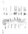
- FIG. 1Ais a cross-section view of a spinal cord 100 of an animal.
- FIG. 1Bis a diagram that illustrates the types of primary afferent axons 110 .
- FIG. 1Cis a schematic diagram of the “Gate Theory” 120 of neuro-modulation for pain management.
- FIG. 1Dis a schematic diagram of mechanisms and neurotransmitters 130 involved in the effects of spinal-cord stimulation (SCS) in neuropathic pain.
- SCSspinal-cord stimulation
- FIG. 1Eis a schematic diagram of Spinal Cord Stimulation (SCS) characteristics 140 .
- FIG. 2Ais a schematic diagram 200 showing electrical stimulation (ES) applied to a rat sciatic nerve.
- FIG. 2Bis a schematic diagram 201 showing the infrared nerve stimulation (INS) of a rat sciatic nerve.
- INSinfrared nerve stimulation
- FIG. 3Ais a schematic drawing of a plurality of light-delivery options 301 from fiber optics/waveguides.
- FIG. 3Bis a block diagram of an infrared-nerve-stimulation-plus-low-level-light therapy system 302 .
- FIG. 4is a schematic representation of a plurality of nerve stimulator light delivery options 401 , according to some embodiments of the present invention.
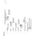
- FIG. 5is a schematic diagram illustrating the mechanisms 501 of low-level light therapy.
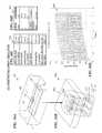
- FIG. 8Ais a table 801 of pulse-signal characteristics associated with a computer simulation of a plurality of aperture sizes for an infrared-light nerve-stimulation device.
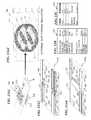
- FIG. 9Ais a graph 901 showing isotemperature contour lines of simulated temperature profiles in a tissue resulting from a simulated exposure to a ten-second-duration pulse train (at a 15-Hz pulse-repetition rate) from an infrared-light nerve stimulation device having a 600- ⁇ m aperture.
- FIG. 9Bis a graph 902 showing the simulated temperature change (delta T in degrees Celsius) one millimeter under the tissue surface versus time (seconds).
- FIG. 9Cis a table 903 showing the pulse-signal characteristics associated with a computer simulation of the 600- ⁇ m aperture.
- FIG. 10Dis a table 1004 showing the physical characteristics of the tissue being simulated with light stimulation from a 400- ⁇ m aperture (and an irradiance of 0.52 J/cm 2 ).
- FIG. 11Cis a table 1103 showing the pulse-signal characteristics used in a computer simulation of stimulation light from a 400- ⁇ m aperture at a surface irradiance having a value of about 0.8 J/cm 2 .
- FIG. 11Dis a table 1104 showing the physical characteristics of the tissue being stimulated with light stimulation from the 400- ⁇ m aperture (and an irradiance of 0.8 J/cm 2 ).
- FIG. 12Ais a graph 1201 showing isotemperature contour lines of simulated temperature profiles in a tissue resulting from a simulated exposure to a ten-second pulse train from an infrared-light nerve stimulation device having a 400- ⁇ m aperture and three channels having one-millimeter (1-mm) spacing between each channel.
- FIG. 12Cis a table 1203 showing the physical characteristics of the tissue being stimulated with light stimulation during the three-channel simulation.
- FIG. 13 A 1is diagram of an infrared-nerve-stimulation-plus-therapeutic-heat (INS-plus-therapeutic heat) device 1301 .
- FIG. 13 A 3is detailed schematic diagram of INS-plus-therapeutic-heat unit 1315 A used for some embodiments of upper cuff portion 1315 of FIG. 13 A 1 .
- FIG. 13Bis a table 1302 showing the pulse-signal characteristics associated with a computer simulation of the temperature profile 1301 .
- FIG. 14Ais a perspective view of an external-cuff-stimulation device 1401 .
- FIG. 14Cis a graph 1403 showing isotemperature contour lines of simulated temperature profiles in both a tissue being simulated and the model 1402 of FIG. 1401 , with a pulse repetition rate of 15 pulses-per-second.
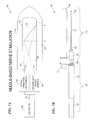
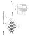
- FIG. 15Ais a perspective view of a penetrating array nerve stimulation system 1501 .
- FIG. 16Ais a simulated temperature profile 1601 conducted for a penetrating array nerve stimulation system 1602 .
- FIG. 16Bis a magnified view of simulated temperature profile 1601 showing the simulated temperature profile near system 1602 .
- FIG. 16Cis a table 1603 showing the pulse-signal characteristics associated with simulated computer simulation of temperature profile 1601 .
- FIG. 16Dis a table 1604 showing the physical characteristics of the simulated tissue being stimulated during the computer simulation of the temperature profile 1601 .
- FIG. 16Eis a graph 1605 showing the maximum temperature down the center of the aperture (degrees Celsius) versus time (seconds).
- FIG. 17 B 1is detailed schematic diagram of INS-plus-therapeutic-heat unit 1703 A used for some embodiments of upper cuff portion 1703 of FIG. 17A .
- FIG. 17 B 2is detailed schematic diagram of INS-plus-therapeutic-heat unit 1703 B used for some embodiments of upper cuff portion 1703 of FIG. 17A .
- FIG. 18Ais a schematic perspective view of a customizable INS-only device 1801 .
- FIG. 18Bis a schematic plan view of device 1801 showing the wiring detail 1802 of the plurality of nerve-stimulation light sources 1810 .
- an optical signalis light (of any suitable wavelength including ultraviolet and infrared wavelengths as well as visible wavelengths) of a signal wavelength being amplified, or of a laser output (and may or may not be modulated with information).
- FIG. 1Ais a cross-section view of a spinal cord 100 of an animal.
- Receptors in the bodye.g., in the skin or other organ or tissue
- the cell bodies for these nerve fibers 101are located in the dorsal root ganglion 102 .
- the nerve fibers 101enter the spinal cord 100 through the dorsal root 103 .
- Some fibersmake synapses with other neurons in the dorsal horn 104 , while others continue up to the brain (sensory fibers converge in dorsal horn 104 of spinal cord 100 , which is one end of the spinal-thalamic tract (STT) that passes pain information to the brain).
- Many cell bodies in the ventral horn 105 of the spinal cord 100send axons through the ventral root 106 to muscles to control movement.
- FIG. 1Bis a diagram that illustrates the types of primary afferent axons 110 .
- an axonis a long, slender projection of a nerve cell, or neuron that conducts electrical impulses away from the neuron's cell body or soma.
- afferent neuronse.g., afferent axons
- Act axons 111are the largest sensory fibers, but are not relevant for pain.
- a ⁇ axons 112carry touch information, and are the largest, most heavily myelinated fibers that play a role in pain processing.
- a ⁇ axons 113 and C axons 114carry different aspects of pain sensing.
- a ⁇ axons 113are slightly myelinated, while C axons 114 have no myelination.
- FIG. 1Cis a schematic diagram of the “Gate Theory” 120 of neuro-modulation for pain management.
- the inhibitory effect of SG 121 neuronal activityis increased by L fiber activity and decreased by S fiber activity.
- T neurons 122transmit information to the brain and other action sites.
- FIG. 1Dis a schematic diagram of mechanisms and neurotransmitters 130 involved in the effects of spinal-cord stimulation (SCS) in neuropathic pain (see FIG. 95.1 in Bonica's Management of Pain , Ballantyne, Jane C., Fishman, Scott M., Rathmell, James P., Chapter 95: Spinal Cord Stimulation, Page 1381, Lippincott Williams & Wilkins, 2009).
- Mechanisms and neurotransmitters 130include ascending and descending control paths, a variety of excitatory and inhibitory neurotransmitters released by different nerve types, and wide dynamic range neurons (WDR) that receive input from all sensory fibers and ascending and descending control paths.
- WDRwide dynamic range neurons
- SCS activation 131 of dorsal column collaterals 132secondarily induces release of gamma-aminobutyric acid (GABA) from dentate-hilus (DH) interneurons, activating mainly GABA-B receptors and decreasing the release of excitatory amino acids from hyperexcited second-order DH WDR neurons 133 .
- GABAgamma-aminobutyric acid
- DHdentate-hilus
- SCS 131also causes cholinergic neurons to activate M4 and M2 muscarinic-type receptors (e.g., acetylcholine (Ach)).
- M4 and M2 muscarinic-type receptorse.g., acetylcholine (Ach)
- the orthodromic SCS-induced activity in the dorsal columns 132might—via neuronal circuitry in the brain stem (or even more rostrally)—induce descending inhibition via serotonergic (e.g., 5-hydroxytryptamine (5-HT)) and noradrenergic (NE) pathways 134 in the dorsolateral funiculus (DLF) 135 , which might contribute to inhibitory influences in the DHs.
- DCdorsal columns 132 ; STT, spinothalamic tract 136 .
- SCS and transcutaneous electrical nerve stimulation (TENS)acts through other means besides just stimulation of A ⁇ fibers 112 .
- transcutaneous electrical nerve stimulationIn transcutaneous electrical nerve stimulation (TENS), electrodes are placed on skin surface, generally near the site of pain. This is effective (with respect to previous rule of thumb) for acute pains such as:
- PNSPeripheral Nerve Stimulation
- FIG. 1Eis a schematic diagram of spinal cord stimulation (SCS) characteristics 140 .
- SCSspinal cord stimulation
- electrode leadsare placed inside vertebral discs, but outside dural membranes at appropriate heights along the spinal column for target area of pain.
- the most common uses for SCSinclude: chronic neuropathic pain, chronic low back pain, refractory angina pectoris (chest pains), interstitial cystitis (inflammation around bladder) and other visceral pains, and complex regional pain syndrome.
- the effect of SCS directed toward the cervical spine 141includes bronchodilation and peripheral vasodilation.
- the effect of SCS directed toward the high thoracic spine 142includes stabilization of intercostals nerves (ICNs), reduction of ischemia and pain, and decreased infarct size.
- the effect of SCS directed toward the middle thoracic spine 143includes decreased colonic spasms, and pain reduction.
- the effect of SCS directed toward the low thoracic spine 144includes peripheral vasodilation.
- the effect of SCS directed toward the sacral spine 145includes decreased bladder spasticity, increased bladder volume, and increased bladder tolerance.
- Deep Brain Stimulationgenerally involves placing electrodes in sensory portions of the thalamus, though motor and pre-frontal cortex can also be a target.
- the present inventionis most successful when the indications are:
- FIG. 2Ais a schematic diagram 200 showing electrical stimulation (ES) applied to a rat sciatic nerve.
- the objective of the ESis the generation of compound-nerve-action potentials (CNAPs) in the gastrocnemius fascicle 210 G.
- CNAPscompound-nerve-action potentials
- a CNAP-versus-time plot 200 Grepresents the CNAP generation in fascicle 210 G caused by ES of the sciatic nerve.
- CNAP-versus-time plot 200 Bshows that ES devices lack the specificity to target the neurons responsible for pain without also activating other sensory or motor neurons as a side effect (e.g., in some embodiments, in addition to generating desired CNAPs in fascicle 210 G, ES of the rat sciatic nerve also generates CNAPs in the biceps femoris fascicle 210 B).
- FIG. 2Bis a schematic diagram 201 showing the infrared nerve stimulation (INS) of a rat sciatic nerve.
- the objective of the INSis to generate CNAPs in fascicle 210 G.
- a CNAP-versus-time plot 201 Grepresents the CNAP generation in fascicle 210 G caused by INS of the sciatic nerve.
- INSprovides specific simulation such that substantially zero CNAPs are generated in non-targeted sensory or motor neurons (e.g., in some embodiments, as shown in CNAP-versus-time plot 201 B, substantially zero CNAPs are generated in fascicle 210 B by INS of the rat sciatic nerve).
- Infrared nerve stimulationprovides more precise neural stimulation compared to electrical stimulation (ES) methods because light is directed in a single direction, it has no stimulation artifact, and the various materials for implantable INS designs can be safer and more biocompatible than current ES devices.
- the preferred target neural tissue for pain relief therapy using either INS or low-level light therapy (LLLT) or both INS and LLLTis the peripheral nervous system, especially: ulnar, median, radial, and other nerves in the arm (neuropathic pain, carpal tunnel, tennis elbow, etc.); femoral, sural, sciatic, and other nerves in the leg (neuropathic pain); and occipital nerve in the neck region (migraines).
- the first two sets of nervescan treat neuropathic pain arising from nerve injury, while the latter may be effective in treating migraines.
- potential target applicationsinclude: lumbar dorsal roots for lower back pain; sacral root for interstitial cystitis as well as incontinence; trigeminal nerve for facial neuralgia; vagus nerve for chronic angina, as well as obesity treatment, epilepsy treatment, and depression treatment; spinal cord stimulator for variety of neuropathic conditions; and a deep brain stimulator for a variety of neuropathic conditions.
- FIG. 3Ais a schematic drawing of a plurality of light-delivery options 301 from fiber optics/waveguides.
- the shape of the laser beam delivered by the fiberis accomplished with a lens, polished tip (facetted or shaped), grating, mirror or reflective coating, or some combination of the above.
- Waveguide 311ends in an angled facet and/or fiber-Bragg grating that reflects or diffracts the light out in a radial or side (“side firing”) direction relative to the light-propagation axis of the waveguide as laser beam 81 .
- Waveguide 312ends in an end facet that transmits the light out in an axial direction relative to the light-propagation axis of the waveguide, as laser beam 82 .
- Waveguide 316ends in a lens-type end facet that transmits and collimates the light out in a parallel beam in an axial direction relative to the light-propagation axis of the waveguide as laser beam 86 .
- Waveguide 317ends in an annular lens-type end facet that transmits and focuses the light out in a conical ring centered about an axial direction relative to the light-propagation axis of the waveguide as laser beam 87 .
- the very end facetis polished and coated with a metallic or dielectric-layered reflective structure to better facilitate the ring-shaped output beam 87 .
- a bundle having a plurality of such fibers and endsare used in combination to get a plurality of beams and/or a plurality of beam shapes in a small area.
- the ends of the plurality of fibersterminate at a plurality of different axial lengths to provide output beams that leave the bundle at different points along the length of the fiber bindle.
- FIG. 3Bis a block diagram of an infrared-nerve-stimulation-plus-low-level-light therapy system 302 .
- system 302includes one or more optical-stimulation light sources 330 configured to emit optical-stimulation light signals 331 toward neural tissue of an animal and one or more low-level light therapy sources 340 configured to emit low-level light therapy light signals 341 (e.g., near-infrared light signals) toward the neural tissue of the animal.
- system 302further includes a controller 320 operatively coupled to optical-stimulation light sources 330 and low-level light therapy sources 340 via one or more wires 321 .
- controller 320is configured to control the emitting of signals 331 and signals 341 such that the signals are efficacious to control pain of the animal.
- a non-invasive direct-light techniqueis used to stimulate a nerve 11 , fascicle 12 , and/or nerve fiber 13 , or a combination of a nerve 11 , fascicle 12 , and/or nerve fiber 13 using laser-light beam 452 .
- non-invasive direct-light techniqueprovides a laser-light beam 452 from a laser-source module (LSM) and/or light-shaping element (LSE), as described above for FIG. 2 , to stimulator the nerve 11 , fascicle 12 , and/or nerve fiber 13 .
- LSMlaser-source module
- LSElight-shaping element
- remote LSM and/or LSEis used to stimulate one or more areas of nerve 11 , fascicle 12 , and/or nerve fiber 13 , wherein light is transmitted via a fiber bundle 451 at the fiber 351 /nerve 11 interface.
- fiber bundle 451uses a remote LSM plus LSE, wherein the light is transmitted via fiber bundle 451 .
- the lightis emitted from the ends of fibers of fiber bundle 451 (e.g., in some embodiments, the ends of the various fibers terminate at a plurality of different locations along the length of fiber bundle 451 ), and/or light is emitted from multiple locations along the length of fiber bundle 451 using inline fiber gratings formed on the individual fibers of fiber bundle 451 .
- an invasive methodis used to stimulate the nerve 11 using a light-transmitting waveguide array 453 implanted into nerve 11 , fascicle 12 , and/or nerve fiber 13 (attached to LSM or LSE) and formed from transmissive material made by micro-molding, micro-machining, and/or photolithography.
- an additional invasive methodis used to stimulate the nerve 11 by implanting a power distribution strip 454 that includes a plurality of light emitting devices that are each capable of stimulating nerve 11 , fascicle 12 and/or individual nerve fiber 13 .
- a combination of light delivery optionsare used to stimulate nerve 11 , fascicle 12 , and/or nerve fiber 13 (i.e., in some embodiments, a combination of one or more of the described techniques, including, laser-light beam 452 , fiber bundle 451 , waveguide array 453 , and/or power-distribution strip 454 are used for stimulating nerve 11 , fascicle 12 , and/or nerve fiber 13 ).
- FIG. 5is a schematic diagram illustrating mechanisms 501 of low-level light therapy (LLLT) (information from, e.g., Hamblin M R, and T M Demidova, Mechanisms of Low Level Light Therapy—an Introduction, Proc SPIE, Vol 6140, art. no. 61001, 1-12, 2006, which is incorporated herein by reference in its entirety).
- LLLTlow-level light therapy
- LLLTis also known as low-level laser therapy, photo-bio-stimulation, or cold laser therapy.
- red or near-infrared light of low powere.g., in some embodiments, within a range of about 1 milliwatts (mW) to about 500 mW) is shone on the desired tissue for several minutes.
- mWmilliwatts
- the LLLT lightis continuous-wave (cw) illumination, while in other embodiments, the LLLT is pulsed.
- Photonsare absorbed by cytochrome c oxidase in mitochondria, which leads to: increased adenosine triphosphate (ATP) production (and thus increased cyclic adenosine monophosphate (cAMP)), increased nitric oxide (NO) production, and increased reaction oxygen species (ROS) production. It is believed that ROS activate cellular pathways designed to cope with low levels of oxidative stress.
- ATPadenosine triphosphate
- NOnitric oxide
- ROSreaction oxygen species
- Redox-sensitive transcription factorsare activated, leading to expression of an array of gene products that prevent apoptosis and cell death, stimulate fibroblast proliferation, migration and collagen synthesis, modulate the inflammatory and anti-oxidant response, and stimulate angiogenesis and tissue repair (e.g., members of the Fos family dimerise with c-Jun to form the AP-1 transcription factor, which upregulates transcription of a diverse range of genes involved in everything from proliferation and differentiation to defense against invasion and cell damage; NF- ⁇ B (nuclear factor kappa-light-chain-enhancer of activated B cells) is a protein complex that controls the transcription of DNA; and LKB1 is a primary upstream kinase of adenine monophosphate-activated protein kinase (AMPK), a necessary element in cell metabolism that is required for maintaining energy homeostasis).
- AMPKadenine monophosphate-activated protein kinase
- LLLTis used to stimulate wound healing, reduce inflammation, or treat acute pain.
- LLLT studiese.g., Huang, Ying-Ying, et al., Biphasic Dose Response in Low Level Light Therapy, Dose-Response, 7:358-383, 2009; Hashmi, Javad T., et al., Effect of Pulsing in Low-Level Light Therapy, Lasers Surg Med., 42 (6): 450-466, August 2010; and Bjordal, Jan M., et al., A systematic review with procedural assessments and meta-analysis of Low Level Laser Therapy in lateral elbow tendinopathy (tennis elbow), BMC Musculoskeletal Disorders, 9:75, 29 May 2008, which are all incorporated herein by reference in their entirety) have shown reduction of certain kinds of acute pain when light is shone directly upon the painful area (e.g., temporary relief of rheumatoid arthritis pain, other joint pain such as neck and knee, and general
- device 602includes a plurality of nerve-stimulation light sources 610 that emit infrared laser-light nerve-stimulation signals 611 (in an inward direction toward the nerve 98 ) configured to trigger nerve-action potentials in the nerve 98 and/or provide pain relief to the animal.
- device 602further includes one or more low-level light therapy units 620 , located on each of one or more outer sides of cuff device 602 (directing light outward) and/or on each of one or more inner sides of cuff device 602 (directing light inward toward the encircled nerve 98 and its individual nerve fascicles or bundles 97 ), wherein low-level light therapy units 620 emit low-level-light-therapy signals 621 that are configured to be efficacious for pain management.
- the one or more low-level light therapy units 620include one or more laser diodes (e.g., in some embodiments, one or more VCSELs; in other embodiments, one or more edge-emitting laser diodes).
- low-level light therapy units 620include one or more light-emitting diodes (LEDs).
- the penetration depth of the lower-level-light-therapy signals 621is in a range of about one to five centimeters (1-5 cm). In other embodiments, the penetration depth of the low-level-light-therapy signals 621 is in any other suitable range.
- low-level light therapy unit 620includes optics to direct signals 621 only to certain locations (e.g., points of inflammation, locations of pain, or other suitable locations).
- low-level light therapy units 620are located both on the inside of cuff 602 and on the outside of cuff 602 in order to target both nerve 98 and the surrounding tissue.
- low-level light therapy units 620include a penetrating array such as described and shown in FIG. 15A and FIG. 15B .
- FIG. 7Ais a schematic diagram of a needle-based nerve-stimulation system 701 .
- system 701is configured to provide acute nerve block diagnostics.
- system 701includes the controller 320 , the one or more wires 321 , the one or more optical-stimulation light sources 330 , and the one or more low-level light therapy sources 340 of FIG. 3B .
- system 701includes controller 320 , one or more wires 321 , and the one or more optical-stimulation light sources 330 of FIG. 3B (but does not include low-level light therapy sources 340 of FIG. 3B ).
- system 701further includes a very narrow needle 711 (e.g., a 22-gauge (0.644 millimeter diameter) needle) having a fiber-optic channel 715 (e.g., having a diameter of approximately 200 to 220 micrometers (200 to 220 ⁇ m)) that is configured to receive optical-stimulation light signals 331 and/or low-level light therapy signals 341 emitted from optical-stimulation light sources 330 and/or low-level light therapy sources 340 , respectively, and transmit these signals into neural tissue of an animal via an optical window 725 of needle 711 .
- a very narrow needle 711e.g., a 22-gauge (0.644 millimeter diameter) needle
- a fiber-optic channel 715e.g., having a diameter of approximately 200 to 220 micrometers (200 to 220 ⁇ m)
- needle 711includes optics 720 (e.g., a mirror and/or lens) configured to deliver and/or focus the signals to the neural tissue of the animal to stimulate sensory neurons in the tissue to reduce pain.
- optics 720e.g., a mirror and/or lens
- needle 711is used in combination with a cannula.
- needle 711has a diameter of approximately 20 to 30 gauge (i.e., a diameter of approximately 0.812 millimeters to 0.255 millimeters).
- system 701is configured to provide acupuncture in order to reduce acute pain, especially headaches.
- needle 711is an acupuncture needle and has a diameter of approximately 100 to 300 micrometers (100 to 300 ⁇ m).
- system 701is configured to deliver only low-level light therapy signals 341 (no optical-stimulation light signals 340 ) to the neural tissue of the animal via needle 711 (e.g., in some embodiments, system 701 applies low-level light therapy to traditional acupoints rather than directly to injured area).
- Such low-level light therapy acupunctureis hypothesized to work by releasing soluble factors into systemic circulation.
- system 701is configured to deliver only optical-stimulation light signals 341 (no low-level light therapy signals 341 ) to the neural tissue of the animal via needle 711 .
- infrared-nerve stimulationprovided by the present invention is used to relieve neuropathic pain, central pain, other chronic pain, and inflammatory pain, visceral pain, and orafacial/head pain.
- low-level light therapyprovided by the present invention is used to relieve acute nociceptive pain, inflammatory pain, and orafacial/head pain.
- acupuncture INS-plus-LLLT systemsprovided by the present invention are used to relieve acute nociceptive pain, inflammatory pain, visceral pain, and orafacial/head pain.
- FIG. 7Bis a side view drawing of a nerve-stimulation needle system 702 used in some embodiments of system 701 of FIG. 7A .
- nerve-stimulation needle system 702includes a optical-fiber cable 721 configured to transmit optical-stimulation signals and/or low-level light therapy signals from optical-stimulation light sources and/or low-level light therapy sources (not shown here—see FIG. 7A ) to needle 711 , which then outputs the signals to the tissue of an animal via optical window 725 .
- the end of optical-fiberis covered with heat-shrink tubing 722 .
- needle adapter 723connects to needle 711 at the needle base 724 of needle 711 , such that the needle adapter 723 , needle base 724 , and needle 711 form removable needle assembly 710 .
- system 702includes a removable sheath 730 and cap 731 configured to protect and keep sterile needle assembly 710 during transit and storage, and during the attachment of needle assembly 710 to optical-fiber cable 721 wherein cap 731 is removed and sheath 730 is used to hold removable needle assembly 710 while it is attached to adaptor 729 on cable assembly 740 .
- the numerical simulationsinclude Monte Carlo simulations of light propagation in tissue, which determines energy density due to photon absorption.
- the numerical simulationsalso include thermal modeling of heat produced by laser sources interacting with photon-absorption heat.
- the numerical simulationswere performed for an external cuff (e.g., see cuff 1401 of FIG. 14A ) placed around the femoral nerve in the leg.
- the simulationswere based on a structure similar to a FINE (flat interface nerve electrode) device such as described by U.S. patent application Ser. No. 13/117,122, titled “CUFF APPARATUS AND METHOD FOR OPTICAL AND/OR ELECTRICAL NERVE STIMULATION OF PERIPHERAL NERVES, which is incorporated herein by reference in its entirety (and which issued as U.S. Pat. No. 8,652,187 on Feb.
- FINEflat interface nerve electrode
- Electrodes of the FINE devicewere replaced with optically emitting vertical-cavity-surface-emitting lasers (VCSELs) for the thermal simulations of the present FINOS (flat interface nerve optical stimulator) and/or FINEOS (flat interface nerve electrode-optical stimulator) device 1401 .
- VCSELsvertical-cavity-surface-emitting lasers
- An electrode-optical stimulatoris also called an optrode.
- configuring device 1401 as an external cuffi.e., a cuff that is implanted within the body of the patient, but which is outside of the nerve bundle
- the optical devicesreplacing the electrodes of a conventional FINE device
- fasciclesbunch of neurons comprising a nerve
- a FINOS/FINEOS deviceis placed around the nerve bundle and squishes the nerve bundle in order to separate and expose the various nerves within the nerve bundle for independent stimulation).
- numerical simulationswere performed for a penetrating array 1502 (see FIG. 15A ) placed in the median or ulnar nerve in the arm.
- FIG. 8Ais a table 801 of pulse-signal characteristics associated with a computer simulation of a plurality of aperture sizes for an infrared-light nerve stimulation device.
- the pulse-signal characteristicsare calculated based on an energy-density requirement having a value of about 0.4 joules-per-square-centimeter (0.4 J/cm 2 ) (i.e., in some embodiments, the energy density required for stimulation at the surface of the tissue to be stimulated is 0.4 J/cm 2 ).
- the available power density of VCSELs used in the infrared-light nerve stimulation devicehas a value of about 160 W/cm 2 (e.g., in some embodiments, 159154.9 milliwatts-per-square-centimeter (159.1549 W/cm 2 ).
- FIG. 8Bis a graph 802 of the simulated penetration depth versus pulse-energy-per-penetration-depth according to the data in table 801 .
- Graph 802shows the diminishing returns of penetration depth with respect to pulse energy.
- FIG. 8Cis a graph 803 showing isotemperature contour lines of the simulated temperature profiles resulting from different aperture diameters versus penetration depth according to the data in table 801 . Approximate temperature values for the five areas of the temperature profile are based on an arbitrary temperature scale of 4 (coolest) to 18 (hottest) and are shown on the 1100- ⁇ m aperture portion of FIG. 8C only for clarity.
- FIG. 9Ais a graph 901 showing isotemperature contour lines of simulated temperature profiles in a tissue resulting from a simulated exposure to a ten-second-duration pulse train (at a 15-Hz pulse-repetition rate) from an infrared-light nerve stimulation device having a 600- ⁇ m aperture.
- the simulationis based on a value of required tissue-surface irradiance for nerve stimulation of about 0.4 J/cm 2 .
- the tissue surfaceis 46 degree Celsius, which is high enough to cause cell death.
- the scale of the temperature profileis calculated by subtracting 310.15 from the value of the actual surface temperature of the tissue measured in Kelvins. For example, the maximum temperature of 46 degrees Celsius (319.15 Kelvin) at the surface of the tissue is shown as about a 9 on the temperature-profile scale that runs from 1 (coolest) to 9 (hottest).
- FIG. 9Cis a table 903 showing the pulse-signal characteristics associated with a computer simulation of the 600- ⁇ m aperture.
- FIG. 9Dis a table 904 showing the physical characteristics of the tissue being stimulated during the computer simulation of the 600- ⁇ m aperture.
- FIG. 10Ais a graph 1001 showing isotemperature contour lines of simulated temperature profiles in a tissue resulting from a simulated exposure to a ten-second-duration pulse train (at a 15-Hz pulse-repetition rate) from an infrared-light nerve stimulation device having a 400- ⁇ m aperture.
- the simulationis performed assuming a surface irradiance having a value of about 0.52 J/cm 2 (above the required surface irradiance for nerve stimulation of 0.4 J/cm 2 ), and the scale of the temperature profile is degrees Celsius. After 10 seconds, the tissue surface is 42.5 degrees Celsius.
- FIG. 10Bis a graph 1002 showing the maximum temperature of the tissue surface (degrees Celsius) versus time (seconds).
- FIG. 10Cis a table 1003 showing the pulse-signal characteristics used in a computer simulation of stimulation light from a 400- ⁇ m aperture at a surface irradiance having a value of about 0.52 J/cm 2 .
- FIG. 10Dis a table 1004 showing the physical characteristics of the tissue being simulated with light stimulation from a 400- ⁇ m aperture (and an irradiance of 0.52 J/cm 2 ).
- FIG. 11Ais a graph 1101 showing isotemperature contour lines of simulated temperature profiles in a tissue resulting from a simulated exposure to a ten-second pulse train (at a 9-Hz pulse-repetition rate) from an infrared-light nerve stimulation device having a 400- ⁇ m aperture.
- the simulationis performed at a surface irradiance having a value of about 0.8 J/cm 2 , the temperature scale is in degrees Celsius, and the pulse repetition rate is decreased to nine Hertz (9 Hz) to keep the tissue temperature under 43 degrees Celsius. After 10 seconds, the tissue surface is 43 degree Celsius.
- the scale of the temperature profileis degrees Celsius.
- FIG. 11Bis a graph 1102 showing the maximum temperature of the tissue surface (in degrees Celsius) versus time (in seconds) for a pulse train of 2.5-millisecond pulses each having 1.04 mJ.
- FIG. 11Cis a table 1103 showing the pulse-signal characteristics used in a computer simulation of stimulation light from a 400- ⁇ m aperture at a surface irradiance having a value of about 0.8 J/cm 2 .
- FIG. 11Dis a table 1104 showing the physical characteristics of the tissue being stimulated with light stimulation from the 400- ⁇ m aperture (and an irradiance of 0.8 J/cm 2 ).
- FIG. 11Eis a graph 1105 of temperature down the center of the aperture (degrees Celsius) versus depth (meters).
- FIG. 12Ais a graph 1201 showing isotemperature contour lines of simulated temperature profiles in a tissue resulting from a simulated exposure to a ten-second pulse train from an infrared-light nerve stimulation device having a 400- ⁇ m aperture and three channels having one-millimeter (1-mm) spacing between each channel.
- the simulationis performed at a surface irradiance having a value of about 0.4 J/cm 2 and the temperature scale is in degrees Celsius.
- the tissue temperaturedoes not exceed 43 degrees Celsius, which minimizes the risk of thermal tissue damage due to the direct laser pulse.
- FIG. 12Bis a table 1202 showing the pulse-signal characteristics used in a computer simulation of stimulation light from a 400- ⁇ m aperture having three channels at one-millimeter (1-mm) spacing.
- FIG. 12Cis a table 1203 showing the physical characteristics of the tissue being stimulated with light stimulation during the three-channel simulation.
- array 1305 and heat spreaders 1310are contained within a body that is made of any other suitable material (e.g., a bio-compatible material such as provided by Hydromer, Inc., 35 Industrial Parkway, Branchburg, N.J. 08876).
- device 1301includes an upper cuff portion 1315 that is placed on a first side of a peripheral nerve 98 of the person, and a lower cuff portion 1316 that is placed on a second, opposite side of peripheral nerve 98 .
- cuff portion 1315 and cuff portion 1316both include a VCSEL array 1305 , one or more heat spreaders 1310 operatively coupled to array 1305 , and a silicone body 1308 that contains the array 1305 and the heat spreaders 1310 .
- device 1301is used in combination with low-level light therapy (e.g., in some embodiments, the present invention provides a system similar to system 302 of FIG. 3B except that optical-stimulation light sources 330 includes infrared-nerve-stimulation-plus-therapeutic-heat device 1301 ).
- FIG. 13 A 2is a simulated temperature profile 1302 for an external-cuff-stimulation device such as INS-plus-therapeutic-heat device 1301 of FIG. 13 A 1 .
- an external-cuff-stimulation devicesuch as INS-plus-therapeutic-heat device 1301 of FIG. 13 A 1 .
- most of the lightis absorbed in the first 200 ⁇ m of tissue, and this drives the required aperture to greater than 400 ⁇ m, and subsequently the total heat dissipated in the implant is quite large.
- the heat loadis the limiting factor for channel scaling.
- FIG. 13 A 4is detailed schematic diagram of INS-plus-therapeutic-heat unit 1315 B used for some embodiments of upper cuff portion 1315 of FIG. 13 A 1 .
- unit 1315 Bincludes a plurality of VCSELs contained in a single package 1325 (e.g., in some embodiments, a VCSEL array), wherein a plurality of heat spreaders 1310 are operatively coupled to the package of VCSELs 1325 , and wherein the package of VCSELs 1325 and the plurality of heat spreaders 1310 are contained within a silicone body 1308 .
- the package of VCSELs 1325emit a plurality optical-stimulation signals 1306 and each of the heat spreaders 1310 transfer heat 1311 away from the package of VCSELs 1325 .
- FIG. 13Cis a table 1304 showing the physical characteristics of the tissue being stimulated during the computer simulation of the temperature profile 1302 .
- FIG. 14Ais a perspective view of an external-cuff-stimulation device 1401 .
- device 1401includes 18 vertical-cavity-surface-emitting lasers (VCSELs) (three-by-three (3 ⁇ 3) array on each of two opposite sides), a 400-1 ⁇ m aperture, 2.5-milliseconds duration, X-pitch of one millimeter (1 mm), Z-pitch of 1 mm, and a 200-milliwatt (200-mW) peak-power output.
- VCSELsvertical-cavity-surface-emitting lasers
- 400-1 ⁇ m aperturethree-by-three (3 ⁇ 3) array on each of two opposite sides
- 400-1 ⁇ m aperture2.5-milliseconds duration
- Z-pitch of 1 mma 200-milliwatt (200-mW) peak-power output
- device 1401is made from a material that includes silicon.
- the dimensions shown on device 1401are in arbitrary units for
- the dimensions of device 1401are ten millimeters (10 mm) in length by two millimeters (2 mm) in height by ten millimeters (10 mm) in width (along the nerve). In other embodiments, other dimensions are used. In some embodiments, the VCSEL efficiency is approximately 25%.
- FIG. 14Bis a perspective view of one-eighth of a 3-way-symmetrical model 1402 of device 1401 that was simulated to solve using symmetry. In some embodiments, no perfusion was taken into account for the simulation analysis.
- FIG. 14Dis a simulated temperature profile 1404 of model 1402 itself.
- the temperature gradient across model 1402is about 0.9° C., which is relatively small compared to the overall temperature rise.
- the key factoris total heat load.
- a 6 Hz repeat ratewill result in 4° C. temperature rise and is more practical if no extra heat spreading is considered.
- FIG. 15Ais a perspective view of a penetrating array nerve stimulation system 1501 .
- the outer epineurium of nerve 98is penetrated with a “spike” electrodes/optrodes device 1502 .
- FIG. 15Bis a perspective view of spike electrodes/optrodes device 1502 .
- VCSELsare placed at the base of each cone 1510 of device 1502 , which is inserted into nerve 98 of FIG. 15A .
- the VCSELsare in a 3 ⁇ 3 array with a 500 ⁇ m pitch (in some such embodiments, an individual 3 ⁇ 3 array has a width of approximately 1.5 millimeters (mm)).
- Zemax® optical-modeling using software from Zemax (Radiant ZEMAX, LLC, 3001 112th Avenue NE, Suite 202, Bellevue, Wash. 98004 USA; www.zemax.com)is performed to determine the light output of the cones 1510 .
- the overall heat loadis determined for repetition rates up to 15 Hertz (Hz).
- FIG. 16Cis a table 1603 showing the pulse-signal characteristics associated with simulated computer simulation of temperature profile 1601 .
- FIG. 16Dis a table 1604 showing the physical characteristics of the tissue being stimulated during the computer simulation of the temperature profile 1601 .
- FIG. 16Eis a graph 1605 showing the maximum temperature down the center of the aperture (degrees Celsius) versus time (seconds).
- FIG. 17Ais a schematic perspective view of an infrared-nerve-stimulation plus therapeutic heat plus low-level light therapy (INS-plus-TH-plus-LLLT) device 1701 .
- device 1701includes a vertical-cavity-surface-emitting laser (VCSEL) array 1705 , one or more low-level light therapy units 1720 that emit low-level-light-therapy signals 1721 that are configured to be efficacious for pain management, and one or more heat spreaders 1710 operatively coupled to array 1705 and/or units 1720 and configured to spread heat generated by array 1705 and/or units 1720 away from array 1705 and/or units 1720 and into surrounding tissue of a person.
- low-level light therapy units 1720are located on each of one or more outer sides of device 1701 (directing light outward) and/or on each of one or more inner sides of device 1701 (directing light inward toward nerve 98 ),
- the one or more low-level light therapy units 1720include one or more laser diodes (e.g., in some embodiments, one or more VCSELs; in other embodiments, one or more edge-emitting laser diodes). In some embodiments, low-level light therapy units 1720 include one or more light-emitting diodes (LEDs). In some embodiments, low-level light therapy unit 1720 includes optics to direct signals 1721 only to certain locations (e.g., points of inflammation, locations of pain, or other suitable locations).
- array 1705 , low-level light therapy units 1720 , and heat spreaders 1710are contained within a silicone body 1706 .
- array 1705 , low-level light therapy units 1720 and heat spreaders 1710are contained within a body that is made of any other suitable material (e.g., a bio-compatible material such as provided by Hydromer, Inc., 35 Industrial Parkway, Branchburg, N.J. 08876).
- units 1720are located on device 1701 such that units 1720 are configured to target both nerve 98 and the surrounding tissue.
- device 1701includes an upper cuff portion 1703 that is placed on a first side of a peripheral nerve 98 of a person, and a lower cuff portion 1704 that is placed on a second, opposite side of peripheral nerve 98 .
- cuff portion 1703 and cuff portion 1704both include a VCSEL array 1705 , one or more low-level light therapy units 1720 , one or more heat spreaders 1710 operatively coupled to array 1705 and/or units 1720 , and a silicone body 1706 that contains the array 1705 , low-level light therapy units 1720 , and the heat spreaders 1710 .
- FIG. 17 B 1is detailed schematic diagram of INS-plus-therapeutic-heat unit 1703 A used for some embodiments of upper cuff portion 1703 of FIG. 17A .
- unit 1703 Aincludes a plurality of vertical-cavity-surface-emitting lasers (VCSELs) 1705 , wherein each VCSEL 1705 is operatively coupled to its own heat spreader 1710 , and wherein the plurality of VCSELs 1705 and the plurality of heat spreaders 1710 are contained within a silicone body 1706 .
- VCSELsvertical-cavity-surface-emitting lasers
- each of the VCSELs 1705emit a plurality of optical-stimulation signals 1707 and each of the heat spreaders 1710 transfer heat 1711 generated by its respective VCSEL 1705 away from that respective VCSEL 1705 .
- low-level light therapy units 1720are located on each of one or more outer sides of device 1703 A (directing light outward toward the surrounding tissue) and/or on each of one or more inner sides of device 1703 A (directing light inward toward nerve 98 ).
- FIG. 17 B 2is detailed schematic diagram of INS-plus-therapeutic-heat unit 1703 B used for some embodiments of upper cuff portion 1703 of FIG. 17A .
- unit 1703 Bincludes a plurality of VCSELs contained in a single package 1725 (e.g., in some embodiments, a VCSEL array), wherein a plurality of heat spreaders 1710 are operatively coupled to the package of VCSELs 1725 , and wherein the package of VCSELs 1725 and the plurality of heat spreaders 1710 are contained within a silicone body 1706 .
- the package of VCSELs 1725emit a plurality optical-stimulation signals 1707 and each of the heat spreaders 1710 transfer heat 1711 away from the package of VCSELs 1325 .
- low-level light therapy units 1720are located on each of one or more outer sides of device 1703 A (directing light outward) and/or on each of one or more inner sides of device 1703 A (directing light inward toward nerve 98 ),
- FIG. 18Ais a schematic perspective view of a customizable INS-only device 1801 .
- device 1801is a cuff device configured to be placed around a nerve (e.g., a peripheral nerve or any other suitable nerve) of an animal in order to provide pain relief to the animal (e.g., in some embodiments, device 1801 includes a cuff apparatus such as described in U.S. patent application Ser. No. 13/117,122 titled “CUFF APPARATUS AND METHOD FOR OPTICAL AND/OR ELECTRICAL NERVE STIMULATION OF PERIPHERAL NERVES”, which is incorporated herein by reference in its entirety, and which issued as U.S. Pat. No. 8,652,187 on Feb. 18, 2014).
- device 1801includes a plurality of nerve-stimulation light sources 1810 that emit infrared laser-light nerve-stimulation signals 1811 configured to trigger nerve-action potentials in the nerve and/or provide pain relief to the animal.
- the plurality of nerve-stimulation light sources 1810form an array of vertical-cavity-surface-emitting lasers (VCSELs) that emit a plurality of optical-stimulation signals 1811 .
- VCSELsvertical-cavity-surface-emitting lasers
- device 1801is used to produce selective stimulation in order to accomplish optimal stimulation (e.g., in some embodiments, the stimulation pattern produced by device 1801 may vary from patient to patient and thus each patient gets his or her own customized stimulation).
- the array of VCSELsare customizable (via additional user controls) to enhance sensory nerve signal processing and resultant interpretation of pain sensation.
- device 1801is configured to treat pain in a more subjective nature (e.g., by eliciting feedback directly from the patient as to whether or not treatment from device 1801 is relieving pain), as opposed to observing whether a patient's limb moves or whether a patient senses hot/cold during treatment.
- FIG. 18Bis a schematic plan view of device 1801 showing the wiring detail 1802 of the plurality of nerve-stimulation light sources 1810 .
- wiring detail 1802includes a plurality of control wires 1815 coupled to the plurality of nerve-stimulation light sources 1810 and configured to transmit control signals to the plurality of nerve-stimulation light sources 1810 .
- the present inventionprovides an apparatus that includes an infrared-light nerve stimulation plus low-level light therapy (INS-plus-LLLT) device configured to be implanted in an animal, wherein the INS-plus-LLLT device includes: a plurality of lasers that output infrared laser-light nerve-stimulation signals; a low-level light-generation unit that outputs low-level light-therapy signals; and a controller operatively coupled to control the plurality of lasers and the low-level light-generation unit.
- INS-plus-LLLTinfrared-light nerve stimulation plus low-level light therapy
- the INS-plus-LLLT deviceis configured to provide pain relief by stimulation of nerves of the body of the patient (e.g., peripheral nerves, dorsal roots, spinal cord, the brain, and any other suitable locations in the body of the animal) using the infrared laser-light nerve-stimulation signals.
- nerves of the body of the patiente.g., peripheral nerves, dorsal roots, spinal cord, the brain, and any other suitable locations in the body of the animal
- the low-level light therapy signalsare provided by the apparatus to enhance the efficacy of the pain relief.
- the low-level light-generation unitis operable to output the low-level light-therapy signals into a tissue of the animal at a penetration depth of approximately one (1) centimeter.
- the low-level light-therapy signalsinclude near-infrared light signals.
- the infrared laser-light nerve-stimulation signalsare output for the duration of a first time period, wherein the low-level light-therapy signals are output for a duration of a second time period, and wherein the second time period is longer than the first time period.
- the first time periodhas at least some overlap with the second time period. In other embodiments, the first time period has no overlap with the second time period.
- the INS-plus-LLLT deviceincludes a cuff electrode.
- the present inventionprovides a method that includes providing an infrared-light nerve stimulation plus low-level light therapy (INS-plus-LLLT) device; implanting the INS-plus-LLLT device in the animal; emitting a plurality of infrared laser-light nerve-stimulation signals from the INS-plus-LLLT device and directing the plurality of infrared laser-light nerve-stimulation signals toward a neural tissue of the animal in order to trigger an action potential response in the neural tissue; and generating a plurality of low-level light-therapy signals using the INS-plus-LLLT device and directing the low-level light-therapy signals toward the neural tissue of the animal in order to reduce an acute pain of the animal.
- INS-plus-LLLTinfrared-light nerve stimulation plus low-level light therapy
- the INS-plus-LLLT methodprovides pain relief by stimulating nerves of the body of the patient (e.g., peripheral nerves, dorsal roots, spinal cord, the brain, and any other suitable locations in the body of the animal).
- nerves of the body of the patiente.g., peripheral nerves, dorsal roots, spinal cord, the brain, and any other suitable locations in the body of the animal.
- the directing of the low-level light-therapy signals to the tissueenhances the efficacy of the pain relief.
- the generating of the plurality of low-level light-therapy signalsincludes directing the plurality of low-level light therapy signals into the neural tissue of the animal at a penetration depth of approximately one (1) centimeter.
- the emitting of the plurality of infrared laser-light nerve-stimulation signalsincludes directing the plurality of infrared laser-light nerve-stimulation signals into the neural tissue of the animal at a penetration depth of approximately 400 ⁇ m.
- the generating of the plurality of low-level light-therapy signalsincludes generating near-infrared light signals.
- the emitting of the plurality of infrared laser-light nerve-stimulation signalsis performed for a duration of a first time period, wherein the generating of the plurality of low-level light-therapy signals is performed for a duration of a second time period, and wherein the second time period is longer than the first time period.
- the first time periodhas at least some overlap with the second time period. In other embodiments, the first time period has no overlap with the second time period.
- the present inventionprovides an apparatus that includes means for emitting a plurality of infrared laser-light nerve-stimulation signals and directing the plurality of infrared laser-light nerve-stimulation signals toward a neural tissue of an animal in order to trigger an action potential response in the neural tissue; means for generating a plurality of low-level light-therapy signals device and directing the low-level light-therapy signals toward the neural tissue of the animal in order to reduce an acute pain of the animal; and means for controlling the means for emitting and the means for generating, wherein the apparatus is configured to be implanted in the animal.
- the INS-plus-LLLT apparatusprovides pain relief by stimulating nerves of the body of the patient (e.g., peripheral nerves, dorsal roots, spinal cord, the brain, and any other suitable locations in the body of the animal) using the plurality of infrared laser-light nerve-stimulation signals emitted by the means for emitting.
- nerves of the body of the patiente.g., peripheral nerves, dorsal roots, spinal cord, the brain, and any other suitable locations in the body of the animal
- the low-level light-therapy signals emitted by the means for generatingenhance the efficacy of the pain relief.
- the means for generating the plurality of low-level light therapy signalsincludes means for generating near-infrared light signals.
- the means for emitting the plurality of infrared laser-light nerve-stimulation signalsis configured to emit the plurality of infrared laser-light nerve-stimulation signals for a duration of a first time period
- the means for generating the plurality of low-level light therapy signalsis configured to generate the plurality of low-level light therapy signals for a duration of a second time period
- the second time periodis longer than the first time period.
- the first time periodhas at least some overlap with the second time period.
- the present inventionincludes embodiments having combinations and subcombinations of the various embodiments and features that are individually described herein (i.e., rather than listing every combinatorial of the elements, this specification includes descriptions of representative embodiments and contemplates embodiments that include some of the features from one embodiment combined with some of the features of another embodiment including combinations of embodiments described herein with embodiments described in the U.S. patents and patent applications that have been incorporated herein by reference). Further, some embodiments include fewer than all the components described as part of any one of the embodiments described herein.
Landscapes
- Health & Medical Sciences (AREA)
- Engineering & Computer Science (AREA)
- Biomedical Technology (AREA)
- Life Sciences & Earth Sciences (AREA)
- General Health & Medical Sciences (AREA)
- Nuclear Medicine, Radiotherapy & Molecular Imaging (AREA)
- Animal Behavior & Ethology (AREA)
- Public Health (AREA)
- Veterinary Medicine (AREA)
- Radiology & Medical Imaging (AREA)
- Pathology (AREA)
- Heart & Thoracic Surgery (AREA)
- Cardiology (AREA)
- Biophysics (AREA)
- Neurosurgery (AREA)
- Vascular Medicine (AREA)
- Physics & Mathematics (AREA)
- Optics & Photonics (AREA)
- Radiation-Therapy Devices (AREA)
Abstract
Description
- U.S. Pat. No. 7,736,382 titled “APPARATUS FOR OPTICAL STIMULATION OF NERVES AND OTHER ANIMAL TISSUE” that issued Jun. 15, 2010 to James S. Webb et al.,
- U.S. Pat. No. 7,883,536 titled “HYBRID OPTICAL-ELECTRICAL PROBES” that issued Feb. 8, 2011 to Mark P. Bendett et al.,
- U.S. patent application Ser. No. 11/536,639 filed Sep. 28, 2006 by James S. Webb et al., titled “MINIATURE APPARATUS AND METHOD FOR OPTICAL STIMULATION OF NERVES AND OTHER ANIMAL TISSUE” (which issued as U.S. Pat. No. 7,988,688 on Aug. 2, 2011),
- U.S. patent application Ser. No. 11/948,912 filed Nov. 30, 2007 by James S. Webb et al., titled “APPARATUS AND METHOD FOR CHARACTERIZING OPTICAL SOURCES USED WITH HUMAN AND ANIMAL TISSUES” (which issued as U.S. Pat. No. 8,929,973 on Jan. 6, 2015),
- U.S. patent application Ser. No. 11/536,642 filed Sep. 28, 2006 by Mark P. Bendett et al., titled “APPARATUS AND METHOD FOR STIMULATION OF NERVES AND AUTOMATED CONTROL OF SURGICAL INSTRUMENTS”,
- U.S. patent application Ser. No. 11/971,874 filed Jan. 9, 2008 by James S. Webb et al., titled “METHOD AND VESTIBULAR IMPLANT USING OPTICAL STIMULATION OF NERVES” (which issued as U.S. Pat. No. 8,012,189 on Sep. 6, 2011),
- U.S. patent application Ser. No. 12/191,301 filed Aug. 13, 2008 by Mark P. Bendett et al., titled “VCSEL ARRAY STIMULATOR APPARATUS AND METHOD FOR LIGHT STIMULATION OF BODILY TISSUES” (which issued as U.S. Pat. No. 8,475,506 on Jul. 2, 2013),
- U.S. patent application Ser. No. 12/254,832 filed Oct. 20, 2008 by Jonathon D. Wells et al., titled “SYSTEM AND METHOD FOR CONDITIONING ANIMAL TISSUE USING LASER LIGHT”,
- U.S. patent application Ser. No. 12/573,848 filed Oct. 5, 2009 by Mark P. Bendett et al., titled “NERVE STIMULATOR AND METHOD USING SIMULTANEOUS ELECTRICAL AND OPTICAL SIGNALS” (which issued as U.S. Pat. No. 8,160,696 on Apr. 17, 2012),
- U.S. patent application Ser. No. 13/013,816 filed Jan. 26, 2011 by Jonathon D. Wells et al., titled “NERVE STIMULATOR AND METHOD USING SIMULTANEOUS ELECTRICAL AND OPTICAL SIGNALS” (which issued as U.S. Pat. No. 8,498,699 on Jul. 30, 2013),
- U.S. patent application Ser. No. 12/693,427 filed Jan. 25, 2010 by Daniel J. Lee et al., titled “OPTICAL STIMULATION OF THE BRAINSTEM AND/OR MIDBRAIN, INCLUDING AUDITORY AREAS” (which issued as U.S. Pat. No. 8,744,570 on Jun. 3, 2014),
- U.S. patent application Ser. No. 12/890,602 filed Sep. 24, 2010 by Jonathon D. Wells et al., titled “LASER-BASED NERVE STIMULATORS FOR, E.G., HEARING RESTORATION IN COCHLEAR PROSTHESES” (which issued as U.S. Pat. No. 8,792,978 on Jul. 29, 2014),
- U.S. patent application Ser. No. 13/117,121 filed May 26, 2011 by Jonathon D. Wells et al., titled “IMPLANTABLE INFRARED NERVE STIMULATION DEVICES FOR PERIPHERAL AND CRANIAL NERVE INTERFACES”,
- U.S. patent application Ser. No. 13/117,121 filed May 26, 2011 by Jonathon D. Wells et al., titled “CUFF APPARATUS AND METHOD FOR OPTICAL AND/OR ELECTRICAL NERVE STIMULATION OF PERIPHERAL NERVES” (which issued as U.S. Pat. No. 8,652,187 on Feb. 18, 2014),
- U.S. patent application Ser. No. 13/117,125 filed May 26, 2011 by Jonathon D. Wells et al., titled “NERVE-PENETRATING APPARATUS AND METHOD FOR OPTICAL AND/OR ELECTRICAL NERVE STIMULATION OF PERIPHERAL NERVES” (which issued as U.S. Pat. No. 8,968,376 on Mar. 3, 2015),
- U.S. patent application Ser. No. 13/117,118 filed May 26, 2011 by Jonathon D. Wells et al., titled “OPTICAL BUNDLE APPARATUS AND METHOD FOR OPTICAL AND/OR ELECTRICAL NERVE STIMULATION OF PERIPHERAL NERVES” (which issued as U.S. Pat. No. 8,864,806 on Oct. 21, 2014),
- U.S. patent application Ser. No. 13/204,610 filed Aug. 5, 2011 by Michael E. Friend, titled “OCULAR IMPLANT AND METHOD FOR TRANSMISSION OF NERVE-STIMULATION LIGHT” (which issued as U.S. Pat. No. 8,709,078 on Apr. 29, 2014),
- U.S. patent application Ser. No. 13/217,197 filed Aug. 24, 2011 by James M. Owen et al., titled “APPARATUS AND METHOD FOR MANAGING CHRONIC PAIN WITH INFRARED LIGHT SOURCES AND HEAT” (which issued as U.S. Pat. No. 8,996,131 on Mar. 31, 2015),
- U.S. Provisional Patent Application 61/349,810 filed May 28, 2010 by Jonathon D. Wells et al., titled “Implantable Infrared Nerve Stimulation Devices for Peripheral and Cranial Nerve Interfaces”,
- U.S. Provisional Patent Application 61/386,461 filed Sep. 24, 2010 by Jonathon D. Wells et al., titled “Implantable Infrared Nerve Stimulation Devices for Peripheral and Cranial Nerve Interfaces”,
- U.S. Provisional Patent Application 61/511,020 filed Jul. 22, 2011 by Ryan C. Stafford, titled “METHOD AND APPARATUS FOR OPTIMIZING AN OPTICALLY STIMULATING COCHLEAR IMPLANT”,
- U.S. Provisional Patent Application 61/511,048 filed Jul. 23, 2011 by Ryan C. Stafford, titled “BROAD WAVELENGTH PROFILE TO HOMOGENIZE THE ABSORPTION PROFILE IN OPTICAL STIMULATION OF NERVES”, and
- U.S. Provisional Patent Application 61/511,050 filed Jul. 23, 2011 by Ryan C. Stafford et al., titled “OPTICAL COCHLEAR IMPLANT WITH ELECTRODE(S) AT THE APICAL END FOR STIMULATION OF APICAL SPIRAL GANGLION CELLS OF THE COCHLEA”, each of which is incorporated herein by reference in its entirety. Benefit is claimed, under 35 U.S.C. 119(e)(1), of Provisional Patent Applications 61/386,461, 61/511,020, 61/511,048, and 61/511,050, listed above.
- orafacial;
- post-operative;
- angina pectoris;
- peripheral neuropathic pain (“best” indication);
- diabetic neuropathies;
- post-trauma; and
- failed back surgery.
- stimulate dorsal roots to mimic SCS without penetrating vertebral discs;
- can also be placed more distally away from cord; and
- works best for similar indications as tens, especially peripheral neuropathies.
A successful trial of TENS or a nerve block is strong indicator that an implanted PNS would work well for a patient.
- central neuropathic pain, especially from degeneration of spinal cord neurons; and
- peripheral neuropathic pain not responding to PNS or SCS
Claims (20)
Priority Applications (1)
| Application Number | Priority Date | Filing Date | Title |
|---|---|---|---|
| US13/234,102US9061135B1 (en) | 2006-09-28 | 2011-09-15 | Apparatus and method for managing chronic pain with infrared and low-level light sources |
Applications Claiming Priority (21)
| Application Number | Priority Date | Filing Date | Title |
|---|---|---|---|
| US11/536,642US20080077200A1 (en) | 2006-09-21 | 2006-09-28 | Apparatus and method for stimulation of nerves and automated control of surgical instruments |
| US11/536,639US7988688B2 (en) | 2006-09-21 | 2006-09-28 | Miniature apparatus and method for optical stimulation of nerves and other animal tissue |
| US11/948,912US8929973B1 (en) | 2005-10-24 | 2007-11-30 | Apparatus and method for characterizing optical sources used with human and animal tissues |
| US11/971,874US8012189B1 (en) | 2007-01-11 | 2008-01-09 | Method and vestibular implant using optical stimulation of nerves |
| US12/191,301US8475506B1 (en) | 2007-08-13 | 2008-08-13 | VCSEL array stimulator apparatus and method for light stimulation of bodily tissues |
| US12/254,832US20100049180A1 (en) | 2007-10-19 | 2008-10-20 | System and method for conditioning animal tissue using laser light |
| US12/573,848US8160696B2 (en) | 2008-10-03 | 2009-10-05 | Nerve stimulator and method using simultaneous electrical and optical signals |
| US12/693,427US8744570B2 (en) | 2009-01-23 | 2010-01-25 | Optical stimulation of the brainstem and/or midbrain, including auditory areas |
| US34981010P | 2010-05-28 | 2010-05-28 | |
| US38646110P | 2010-09-24 | 2010-09-24 | |
| US12/890,602US8792978B2 (en) | 2010-05-28 | 2010-09-24 | Laser-based nerve stimulators for, E.G., hearing restoration in cochlear prostheses and method |
| US13/013,816US8498699B2 (en) | 2008-10-03 | 2011-01-26 | Method and nerve stimulator using simultaneous electrical and optical signals |
| US13/117,125US8968376B2 (en) | 2010-05-28 | 2011-05-26 | Nerve-penetrating apparatus and method for optical and/or electrical nerve stimulation of peripheral nerves |
| US13/117,121US20110295345A1 (en) | 2010-05-28 | 2011-05-26 | Implantable infrared nerve stimulation devices for peripheral and cranial nerve interfaces |
| US13/117,118US8864806B2 (en) | 2010-05-28 | 2011-05-26 | Optical bundle apparatus and method for optical and/or electrical nerve stimulation of peripheral nerves |
| US201161511020P | 2011-07-22 | 2011-07-22 | |
| US201161511048P | 2011-07-23 | 2011-07-23 | |
| US201161511050P | 2011-07-23 | 2011-07-23 | |
| US13/204,610US8709078B1 (en) | 2011-08-03 | 2011-08-05 | Ocular implant with substantially constant retinal spacing for transmission of nerve-stimulation light |
| US13/217,197US8996131B1 (en) | 2006-09-28 | 2011-08-24 | Apparatus and method for managing chronic pain with infrared light sources and heat |
| US13/234,102US9061135B1 (en) | 2006-09-28 | 2011-09-15 | Apparatus and method for managing chronic pain with infrared and low-level light sources |
Publications (1)
| Publication Number | Publication Date |
|---|---|
| US9061135B1true US9061135B1 (en) | 2015-06-23 |
Family
ID=52707954
Family Applications (2)
| Application Number | Title | Priority Date | Filing Date |
|---|---|---|---|
| US13/217,197Expired - Fee RelatedUS8996131B1 (en) | 2006-09-28 | 2011-08-24 | Apparatus and method for managing chronic pain with infrared light sources and heat |
| US13/234,102Expired - Fee RelatedUS9061135B1 (en) | 2006-09-28 | 2011-09-15 | Apparatus and method for managing chronic pain with infrared and low-level light sources |
Family Applications Before (1)
| Application Number | Title | Priority Date | Filing Date |
|---|---|---|---|
| US13/217,197Expired - Fee RelatedUS8996131B1 (en) | 2006-09-28 | 2011-08-24 | Apparatus and method for managing chronic pain with infrared light sources and heat |
Country Status (1)
| Country | Link |
|---|---|
| US (2) | US8996131B1 (en) |
Cited By (14)
| Publication number | Priority date | Publication date | Assignee | Title |
|---|---|---|---|---|
| US10016600B2 (en) | 2013-05-30 | 2018-07-10 | Neurostim Solutions, Llc | Topical neurological stimulation |
| WO2020181055A1 (en)* | 2019-03-05 | 2020-09-10 | The General Hospital Corporation | Low-level light therapy for restoring gut microbiota |
| US10933251B1 (en) | 2020-06-17 | 2021-03-02 | Jonathan M Borkum | System for noninvasive pulsed magnetic induction heating of acupoints for the neurorehabilitation of stroke and brain injury, and for the prevention and treatment of dementia, age-related cognitive decline, and depression |
| US10953225B2 (en) | 2017-11-07 | 2021-03-23 | Neurostim Oab, Inc. | Non-invasive nerve activator with adaptive circuit |
| US11077301B2 (en) | 2015-02-21 | 2021-08-03 | NeurostimOAB, Inc. | Topical nerve stimulator and sensor for bladder control |
| US11229789B2 (en) | 2013-05-30 | 2022-01-25 | Neurostim Oab, Inc. | Neuro activator with controller |
| US11458311B2 (en) | 2019-06-26 | 2022-10-04 | Neurostim Technologies Llc | Non-invasive nerve activator patch with adaptive circuit |
| US11458329B2 (en) | 2016-07-27 | 2022-10-04 | Z2020, Llc | Componentry and devices for light therapy delivery and methods related thereto |
| US11730958B2 (en) | 2019-12-16 | 2023-08-22 | Neurostim Solutions, Llc | Non-invasive nerve activator with boosted charge delivery |
| US11813476B1 (en)* | 2016-12-16 | 2023-11-14 | Erchonia Corporation, Llc | Methods of treating the brain and nervous system using light therapy |
| US11964162B1 (en) | 2022-12-20 | 2024-04-23 | Jonathan M Borkum | Methods and apparatuses for activation of Zusanli ST36 acupoint and other acupoints by combined heating and pulsed magnetic activation |
| US12048852B2 (en)* | 2022-07-05 | 2024-07-30 | StimuSIL, Inc. | Dermal light delivery device for light therapy |
| WO2024159057A1 (en)* | 2023-01-26 | 2024-08-02 | Case Western Reserve University | Treatment of chronic pain via direct photobiomodulation of a nerve |
| US12194307B2 (en) | 2022-12-20 | 2025-01-14 | Jonathan M Borkum | Methods and apparatuses for activation of Zusanli ST36 acupoint and other acupoints by combined heating and pulsed magnetic activation |
Families Citing this family (7)
| Publication number | Priority date | Publication date | Assignee | Title |
|---|---|---|---|---|
| US10384076B2 (en)* | 2010-08-17 | 2019-08-20 | Koninklijke Philips N.V. | Flexible light therapy device, a plaster and a bandage |
| US9314399B2 (en) | 2012-03-06 | 2016-04-19 | Valencia Technologies Corporation | Implantable electroacupuncture system and method for treating dyslipidemia and obesity |
| US9827421B2 (en)* | 2012-03-12 | 2017-11-28 | Valencia Technologies Corporation | Methods and systems for treating a chronic low back pain condition using an implantable electroacupuncture device |
| PT3349844T (en) | 2015-09-15 | 2021-03-29 | Amerivision Int Inc | Apparatus and method for ocular microcurrent stimulation therapy |
| EP4272811A3 (en)* | 2017-11-30 | 2024-02-07 | Case Western Reserve University | System for long-term modulation of peripheral nerve activity with light |
| JP7373565B2 (en) | 2018-11-20 | 2023-11-02 | エヌユーエネルキ, インコーポレイテッド | An electrical stimulation device that applies frequency and peak voltage that are inversely proportional to each other. |
| ES2961009T3 (en) | 2018-12-20 | 2024-03-07 | I Lumen Scient Inc | Microcurrent stimulation therapy system |
Citations (199)
| Publication number | Priority date | Publication date | Assignee | Title |
|---|---|---|---|---|
| US3786861A (en) | 1971-04-12 | 1974-01-22 | Battelle Memorial Institute | Heat pipes |
| US4064872A (en) | 1976-09-02 | 1977-12-27 | Ashley-Butler, Inc. | Temperature measuring device of a liquid crystal laminate |
| US4215694A (en) | 1978-06-01 | 1980-08-05 | Isakov Viktor L | Laser therapy apparatus |
| US4232678A (en) | 1977-05-16 | 1980-11-11 | Joseph Skovajsa | Device for the local treatment of a patient, and more particularly applicable in acupuncture and auriculotheraphy |
| US4296995A (en) | 1980-02-01 | 1981-10-27 | International Telephone And Telegraph Corporation | Optical fiber beam splitter couplers employing coatings with dichroic properties |
| US4558703A (en) | 1982-05-27 | 1985-12-17 | Hermann Mark | Vestibular stimulation method |
| US4566935A (en) | 1984-07-31 | 1986-01-28 | Texas Instruments Incorporated | Spatial light modulator and method |
| US4596992A (en) | 1984-08-31 | 1986-06-24 | Texas Instruments Incorporated | Linear spatial light modulator and printer |
| US4671285A (en) | 1984-04-20 | 1987-06-09 | Judith Walker | Treatment of human neurological problems by laser photo simulation |
| US4681791A (en) | 1985-01-30 | 1987-07-21 | Pilot Ink Co., Ltd. | Thermochromic textile material |
| US4724835A (en) | 1984-03-06 | 1988-02-16 | Pain Suppression Labs, Inc. | Laser therapeutic device |
| US4768516A (en) | 1983-10-14 | 1988-09-06 | Somanetics Corporation | Method and apparatus for in vivo evaluation of tissue composition |
| US4813418A (en) | 1987-02-02 | 1989-03-21 | Staodynamics, Inc. | Nerve fiber stimulation using symmetrical biphasic waveform applied through plural equally active electrodes |
| US4840485A (en) | 1986-12-17 | 1989-06-20 | I.S.S. (U.S.A.) Inc. | Frequency domain cross-correlation fluorometry with phase-locked loop frequency synthesizers |
| US4928695A (en) | 1989-02-17 | 1990-05-29 | Leon Goldman | Laser diagnostic and treatment device |
| US4930504A (en) | 1987-11-13 | 1990-06-05 | Diamantopoulos Costas A | Device for biostimulation of tissue and method for treatment of tissue |
| US4972331A (en) | 1989-02-06 | 1990-11-20 | Nim, Inc. | Phase modulated spectrophotometry |
| US4989605A (en) | 1989-03-31 | 1991-02-05 | Joel Rossen | Transcutaneous electrical nerve stimulation (TENS) device |
| US5062428A (en) | 1990-06-04 | 1991-11-05 | Nim Incorporated | Method and device for in vivo diagnosis detecting IR emission by body organ |
| US5088493A (en) | 1984-08-07 | 1992-02-18 | Sclavo, S.P.A. | Multiple wavelength light photometer for non-invasive monitoring |
| US5122974A (en) | 1989-02-06 | 1992-06-16 | Nim, Inc. | Phase modulated spectrophotometry |
| US5139025A (en) | 1983-10-14 | 1992-08-18 | Somanetics Corporation | Method and apparatus for in vivo optical spectroscopic examination |
| US5151909A (en) | 1990-10-16 | 1992-09-29 | Laserscope | Frequency doubled solid state laser having programmable pump power modes and method for controllable lasers |
| US5150704A (en) | 1986-06-23 | 1992-09-29 | Fuji Electric Co., Ltd. | Laser therapeutic apparatus |
| US5152278A (en) | 1990-08-28 | 1992-10-06 | Applied Medical Resources, Inc. | Surgical endoscope apparatus |
| US5187672A (en) | 1989-02-06 | 1993-02-16 | Nim Incorporated | Phase modulation spectroscopic system |
| US5192278A (en) | 1985-03-22 | 1993-03-09 | Massachusetts Institute Of Technology | Multi-fiber plug for a laser catheter |
| US5212386A (en) | 1991-12-13 | 1993-05-18 | I.S.S. (U.S.A.) Inc. | High speed cross-correlation frequency domain fluorometry-phosphorimetry |
| US5213093A (en) | 1991-05-29 | 1993-05-25 | Applied Vascular Devices, Inc. | Endoscope with non-circular probe and method of making same |
| US5213105A (en) | 1990-12-04 | 1993-05-25 | Research Corporation Technologies, Inc. | Frequency domain optical imaging using diffusion of intensity modulated radiation |
| US5257202A (en) | 1989-02-13 | 1993-10-26 | Research Corporation Technologies, Inc. | Method and means for parallel frequency acquisition in frequency domain fluorometry |
| US5259382A (en) | 1991-03-04 | 1993-11-09 | Kronberg James W | Optical transcutaneous bilirubin detector |
| US5261822A (en) | 1993-01-12 | 1993-11-16 | Iatrotech, Inc. | Surgical refractive laser calibration device |
| US5323010A (en) | 1992-12-01 | 1994-06-21 | I.S.S. (Usa) Inc. | Time resolved optical array detectors and CCD cameras for frequency domain fluorometry and/or phosphorimetry |
| US5327902A (en) | 1993-05-14 | 1994-07-12 | Lemmen Roger D | Apparatus for use in nerve conduction studies |
| US5353799A (en) | 1991-01-22 | 1994-10-11 | Non Invasive Technology, Inc. | Examination of subjects using photon migration with high directionality techniques |
| US5386827A (en) | 1993-03-30 | 1995-02-07 | Nim Incorporated | Quantitative and qualitative in vivo tissue examination using time resolved spectroscopy |
| US5402778A (en) | 1993-01-19 | 1995-04-04 | Nim Incorporated | Spectrophotometric examination of tissue of small dimension |
| US5419312A (en) | 1993-04-20 | 1995-05-30 | Wildflower Communications, Inc. | Multi-function endoscope apparatus |
| US5430175A (en) | 1993-11-30 | 1995-07-04 | Cornell Research Foundation, Inc. | Caged carboxyl compounds and use thereof |
| US5445146A (en) | 1995-03-31 | 1995-08-29 | Bellinger; Gary J. | Biological tissue stimulation by low level optical energy |
| US5464960A (en) | 1993-01-12 | 1995-11-07 | Iatrotech, Inc. | Laser calibration device |
| US5480482A (en) | 1991-11-04 | 1996-01-02 | The United States Of America As Represented By The Secretary Of The Navy | Reversible thermochromic pigments |
| US5484432A (en) | 1985-09-27 | 1996-01-16 | Laser Biotech, Inc. | Collagen treatment apparatus |
| US5548604A (en) | 1993-03-19 | 1996-08-20 | Toepel; Michael P. | Compact hand held medical device laser |
| US5553614A (en) | 1988-12-21 | 1996-09-10 | Non-Invasive Technology, Inc. | Examination of biological tissue using frequency domain spectroscopy |
| US5564417A (en) | 1991-01-24 | 1996-10-15 | Non-Invasive Technology, Inc. | Pathlength corrected oximeter and the like |
| US5608519A (en) | 1995-03-20 | 1997-03-04 | Gourley; Paul L. | Laser apparatus and method for microscopic and spectroscopic analysis and processing of biological cells |
| US5704899A (en) | 1995-10-10 | 1998-01-06 | Conceptus, Inc. | Protective sheath for a fiberoptic image guide within an articulated endoscope |
| US5754578A (en) | 1996-06-24 | 1998-05-19 | W. L. Gore & Associates, Inc. | 1250-1650 nm vertical cavity surface emitting laser pumped by a 700-1050 nm vertical cavity surface emitting laser |
| US5755752A (en) | 1992-04-24 | 1998-05-26 | Segal; Kim Robin | Diode laser irradiation system for biological tissue stimulation |
| US5792051A (en) | 1988-12-21 | 1998-08-11 | Non-Invasive Technology, Inc. | Optical probe for non-invasive monitoring of neural activity |
| US5796889A (en) | 1996-03-13 | 1998-08-18 | E-Tek Dynamics, Inc. | Integrated WDM coupler devices for fiberoptic networks |
| US5799030A (en) | 1996-07-26 | 1998-08-25 | Honeywell Inc. | Semiconductor device with a laser and a photodetector in a common container |
| US5851223A (en) | 1991-05-21 | 1998-12-22 | Medi Consultants, Inc. | Combination non-intrusive analgesic neuroaugmentive system and method triple-modulated gigatens with optional bipolar spike |
| US5899865A (en) | 1988-12-21 | 1999-05-04 | Non-Invasive Technology, Inc. | Localization of abnormal breast tissue using time-resolved spectroscopy |
| US5913884A (en) | 1996-09-19 | 1999-06-22 | The General Hospital Corporation | Inhibition of fibrosis by photodynamic therapy |
| US6048359A (en) | 1997-08-25 | 2000-04-11 | Advanced Photodynamic Technologies, Inc. | Spatial orientation and light sources and method of using same for medical diagnosis and photodynamic therapy |
| US6055110A (en) | 1996-07-02 | 2000-04-25 | Inviso, Inc. | Compact display system controlled by eye position sensor system |
| WO2000025112A1 (en) | 1998-10-28 | 2000-05-04 | Peter Rolfe | Optical monitoring |
| US6066127A (en) | 1997-09-30 | 2000-05-23 | Nidek Co., Ltd. | Laser treatment apparatus |
| US6074411A (en) | 1998-04-04 | 2000-06-13 | Lai; Ming | Multiple diode laser apparatus and method for laser acupuncture therapy |
| US6104957A (en) | 1998-08-21 | 2000-08-15 | Alo; Kenneth M. | Epidural nerve root stimulation with lead placement method |
| US6110195A (en) | 1998-06-01 | 2000-08-29 | Altralight, Inc. | Method and apparatus for surgical and dermatological treatment by multi-wavelength laser light |
| US6152882A (en) | 1999-01-26 | 2000-11-28 | Impulse Dynamics N.V. | Apparatus and method for chronic measurement of monophasic action potentials |
| US6171239B1 (en) | 1998-08-17 | 2001-01-09 | Emory University | Systems, methods, and devices for controlling external devices by signals derived directly from the nervous system |
| US6184542B1 (en) | 1998-06-16 | 2001-02-06 | Princeton Lightwave | Superluminescent diode and optical amplifier with extended bandwidth |
| US6224969B1 (en) | 1997-09-01 | 2001-05-01 | Stichting Voor De Technische Wetenschappen | Optical phantom suitable for stimulating the optical properties of biological material and a method of producing said phantom |
| US6246892B1 (en) | 1991-01-24 | 2001-06-12 | Non-Invasive Technology | Phase modulation spectroscopy |
| US6254637B1 (en) | 2000-04-10 | 2001-07-03 | Lucid Korea Co., Ltd. | Artificial cornea and implantation thereof |
| US6258082B1 (en) | 1999-05-03 | 2001-07-10 | J. T. Lin | Refractive surgery and presbyopia correction using infrared and ultraviolet lasers |
| US6257759B1 (en) | 1998-06-26 | 2001-07-10 | Medical Indicators, Inc. | Liquid crystal thermometer |
| US6263221B1 (en) | 1991-01-24 | 2001-07-17 | Non-Invasive Technology | Quantitative analyses of biological tissue using phase modulation spectroscopy |
| US6267779B1 (en) | 1999-03-29 | 2001-07-31 | Medelaser, Llc | Method and apparatus for therapeutic laser treatment |
| US6284078B1 (en) | 1994-11-22 | 2001-09-04 | Medical Indicators, Inc. | Method for preparing an improved liquid crystal clinical thermometer |
| US6294109B1 (en) | 1995-06-13 | 2001-09-25 | The United States Of America As Represented By The Secretary Of The Navy | Ferroelectric and electroclinic liquid crystal materials with sub-ambient temperature stability, broad operation range, and fast dynamic response |
| US6301279B1 (en) | 1999-04-16 | 2001-10-09 | Princeton Lightwave Inc. | Semiconductor diode lasers with thermal sensor control of the active region temperature |
| US6310083B1 (en) | 1998-12-21 | 2001-10-30 | University Of Maryland Boitechnology Institute | Caged amino acid derivatives bearing photolabile protective groups |
| US6312451B1 (en) | 1999-03-23 | 2001-11-06 | Jackson Streeter | Low level laser therapy apparatus |
| US6314324B1 (en) | 1999-05-05 | 2001-11-06 | Respironics, Inc. | Vestibular stimulation system and method |
| US6324429B1 (en) | 1998-05-08 | 2001-11-27 | Massachusetts Eye And Ear Infirmary | Chronically implantable retinal prosthesis |
| US6330388B1 (en) | 1999-01-27 | 2001-12-11 | Northstar Photonics, Inc. | Method and apparatus for waveguide optics and devices |
| US6339606B1 (en) | 1998-06-16 | 2002-01-15 | Princeton Lightwave, Inc. | High power semiconductor light source |
| US6353226B1 (en) | 1998-11-23 | 2002-03-05 | Abbott Laboratories | Non-invasive sensor capable of determining optical parameters in a sample having multiple layers |
| US6358272B1 (en) | 1995-05-16 | 2002-03-19 | Lutz Wilden | Therapy apparatus with laser irradiation device |
| US6363188B1 (en) | 1999-10-22 | 2002-03-26 | Princeton Lightwave, Inc. | Mode expander with co-directional grating |
| US6417524B1 (en) | 1996-06-05 | 2002-07-09 | Princeton Lightwave Inc. | Light emitting semiconductor device |
| US6421474B2 (en) | 1999-06-01 | 2002-07-16 | Picolight Incorporated | Electro-opto mechanical assembly for coupling a light source or reciever to an optical waveguide |
| US6444313B1 (en) | 2001-01-05 | 2002-09-03 | The Pilot Ink Co., Ltd. | Thermochromic acrylic synthetic fiber, its processed article, and process for producing thermochromic acrylic synthetic fiber |
| US6456866B1 (en) | 1999-09-28 | 2002-09-24 | Dustin Tyler | Flat interface nerve electrode and a method for use |
| US6459715B1 (en) | 1999-05-10 | 2002-10-01 | Princeton Lightwave, Inc. | Master-oscillator grating coupled power amplifier with angled amplifier section |
| US6475800B1 (en) | 1999-07-22 | 2002-11-05 | Instrumentation Metrics, Inc. | Intra-serum and intra-gel for modeling human skin tissue |
| US6488704B1 (en) | 2001-05-07 | 2002-12-03 | Biomed Solutions, Llc | Implantable particle measuring apparatus |
| US6493476B2 (en) | 2000-11-27 | 2002-12-10 | Teem Photonics | Apparatus and method for integrated photonic devices having gain and wavelength-selectivity |
| US6505075B1 (en) | 1999-05-29 | 2003-01-07 | Richard L. Weiner | Peripheral nerve stimulation method |
| US6542772B1 (en) | 1994-12-02 | 2003-04-01 | Non-Invasive Technology, Inc. | Examination and imaging of biological tissue |
| US6542530B1 (en) | 2000-10-27 | 2003-04-01 | Chan-Long Shieh | Electrically pumped long-wavelength VCSEL and methods of fabrication |
| US6546291B2 (en) | 2000-02-16 | 2003-04-08 | Massachusetts Eye & Ear Infirmary | Balance prosthesis |
| US6556611B1 (en) | 1999-05-10 | 2003-04-29 | Princeton Lightwave, Inc. | Wide stripe distributed bragg reflector lasers with improved angular and spectral characteristics |
| US6564076B1 (en) | 1988-12-21 | 2003-05-13 | Non-Invasive Technology, Inc. | Time-resolved spectroscopic apparatus and method using streak camera |
| US6585411B2 (en) | 2001-11-02 | 2003-07-01 | Illinois Tool Works Inc. | Aerosol dispenser temperature indicator |
| US6592611B1 (en) | 2000-10-10 | 2003-07-15 | Robert H. Zawada | Violation of time reversal invariance in living tissue |
| US6639930B2 (en) | 2001-01-11 | 2003-10-28 | Princeton, Lightwave, Inc. | Multi-level closed loop resonators and method for fabricating same |
| US20030236458A1 (en) | 1999-08-03 | 2003-12-25 | Biophysica Llc | Spectroscopic systems and methods for detecting tissue properties |
| US6669765B2 (en) | 1999-01-28 | 2003-12-30 | The Pilot Ink Co., Ltd. | Thermochromic dry offset ink, and printed article produced using the same |
| US6669379B2 (en) | 2002-04-01 | 2003-12-30 | Princeton Lightwave, Inc. | Method of attaching optical fiber in alignment with a light source in an optical module |
| US6688783B2 (en) | 2002-03-25 | 2004-02-10 | Princeton Lightwave, Inc. | Method of fabricating an optical module including a lens attached to a platform of the optical module |
| US6735475B1 (en) | 2001-01-30 | 2004-05-11 | Advanced Bionics Corporation | Fully implantable miniature neurostimulator for stimulation as a therapy for headache and/or facial pain |
| US6735474B1 (en) | 1998-07-06 | 2004-05-11 | Advanced Bionics Corporation | Implantable stimulator system and method for treatment of incontinence and pain |
| US6744548B2 (en) | 2000-01-20 | 2004-06-01 | Princeton Lightwave, Inc. | Resonant enhanced modulator (REM) |
| US6746473B2 (en) | 2001-03-02 | 2004-06-08 | Erchonia Patent Holdings, Llc | Therapeutic laser device |
| US6748275B2 (en) | 1999-05-05 | 2004-06-08 | Respironics, Inc. | Vestibular stimulation system and method |
| US20040225339A1 (en) | 2002-12-20 | 2004-11-11 | Palomar Medical Technologies Inc. | Light treatments for acne and other disorders of follicles |
| US6823109B2 (en) | 2000-03-01 | 2004-11-23 | Nippon Sheet Glass, Co., Ltd. | Optical fiber-lens array |
| USRE38670E1 (en) | 1997-08-29 | 2004-12-14 | Asah Medico A/S | Apparatus for tissue treatment |
| US6836685B1 (en) | 1998-04-07 | 2004-12-28 | William R. Fitz | Nerve stimulation method and apparatus for pain relief |
| US6871084B1 (en) | 2000-07-03 | 2005-03-22 | Srico, Inc. | High-impedance optical electrode |
| US20050099824A1 (en) | 2000-08-04 | 2005-05-12 | Color Kinetics, Inc. | Methods and systems for medical lighting |
| US6902528B1 (en) | 1999-04-14 | 2005-06-07 | Stereotaxis, Inc. | Method and apparatus for magnetically controlling endoscopes in body lumens and cavities |
| US6909826B2 (en) | 1999-10-28 | 2005-06-21 | Princeton Lightwave, Inc. | Multiple grating optical waveguide monitor |
| US20050143789A1 (en) | 2001-01-30 | 2005-06-30 | Whitehurst Todd K. | Methods and systems for stimulating a peripheral nerve to treat chronic pain |
| US6921413B2 (en) | 2000-08-16 | 2005-07-26 | Vanderbilt University | Methods and devices for optical stimulation of neural tissues |
| US6953341B2 (en) | 2003-08-20 | 2005-10-11 | Oralum, Llc | Toothpick for light treatment of body structures |
| US6956650B2 (en) | 2001-01-12 | 2005-10-18 | General Hospital Corporation | System and method for enabling simultaneous calibration and imaging of a medium |
| US6980579B2 (en) | 2000-06-23 | 2005-12-27 | Picolight Incorporated | Temperature compensated lasers |
| US6989023B2 (en) | 2003-07-08 | 2006-01-24 | Oralum, Llc | Hygienic treatments of body structures |
| US7003353B1 (en) | 2002-12-10 | 2006-02-21 | Quallion Llc | Photovoltaic powered charging apparatus for implanted rechargeable batteries |
| US7004645B2 (en) | 2003-04-30 | 2006-02-28 | Agilent Technologies, Inc. | VCSEL array configuration for a parallel WDM transmitter |
| US7006749B2 (en) | 2002-08-07 | 2006-02-28 | Dornier Medtech Laser Gmbh | Laser system with fiber-bound communication |
| US7010356B2 (en) | 2001-10-31 | 2006-03-07 | London Health Sciences Centre Research Inc. | Multichannel electrode and methods of using same |
| US7031363B2 (en) | 2003-10-29 | 2006-04-18 | Finisar Corporation | Long wavelength VCSEL device processing |
| US7040805B1 (en) | 2004-05-24 | 2006-05-09 | The United States Of America As Represented By The Secretary Of The Air Force | Method of infrared thermography |
| US7068878B2 (en) | 2003-01-24 | 2006-06-27 | University Of Washington | Optical beam scanning system for compact image display or image acquisition |
| US7069083B2 (en) | 2002-12-13 | 2006-06-27 | Advanced Neuromodulation Systems, Inc. | System and method for electrical stimulation of the intervertebral disc |
| US20060155348A1 (en)* | 2004-11-15 | 2006-07-13 | Decharms Richard C | Applications of the stimulation of neural tissue using light |
| US7079900B2 (en) | 1999-03-24 | 2006-07-18 | Second Sight Medical Products, Inc. | Electrode array for neural stimulation |
| US20060161218A1 (en) | 2003-11-26 | 2006-07-20 | Wicab, Inc. | Systems and methods for treating traumatic brain injury |
| US20060167564A1 (en) | 2005-01-10 | 2006-07-27 | Flaherty J C | Limb and digit movement system |
| US7085300B2 (en) | 2001-12-28 | 2006-08-01 | Finisar Corporation | Integral vertical cavity surface emitting laser and power monitor |
| US7095770B2 (en) | 2001-12-20 | 2006-08-22 | Finisar Corporation | Vertical cavity surface emitting laser including indium, antimony and nitrogen in the active region |
| US7116886B2 (en) | 2002-12-17 | 2006-10-03 | International Business Machines Corporation | Devices and methods for side-coupling optical fibers to optoelectronic components |
| US7124810B2 (en) | 2004-07-20 | 2006-10-24 | Hon Hai Precision Industry Co., Ltd. | Heat pipe having wick structure |
| US7131968B2 (en) | 2003-06-02 | 2006-11-07 | Carl Zeiss Meditec Ag | Apparatus and method for opthalmologic surgical procedures using a femtosecond fiber laser |
| US20060276861A1 (en) | 2005-06-01 | 2006-12-07 | Lin J T | Non-invasive method and system for the treatment of snoring and nasal obstruction |
| US7156866B1 (en) | 2003-10-15 | 2007-01-02 | Riggs Jeffrey M | Holistic method of treating injured or pathologic tissue with a laser |
| US7160289B2 (en) | 2003-03-28 | 2007-01-09 | Vandolay, Inc. | Vascular occlusion systems and methods |
| US7177081B2 (en) | 2001-03-08 | 2007-02-13 | Silicon Light Machines Corporation | High contrast grating light valve type device |
| US20070053996A1 (en) | 2005-07-22 | 2007-03-08 | Boyden Edward S | Light-activated cation channel and uses thereof |
| US7190993B2 (en) | 2003-11-04 | 2007-03-13 | Medtronic, Inc. | Implantable medical device having optical fiber for sensing electrical activity |
| US7194063B2 (en) | 2005-02-10 | 2007-03-20 | Brookhaven Science Associates, Llc | Methods for implementing microbeam radiation therapy |
| US7225028B2 (en) | 2004-05-28 | 2007-05-29 | Advanced Bionics Corporation | Dual cochlear/vestibular stimulator with control signals derived from motion and speech signals |
| US7231256B2 (en) | 2005-03-11 | 2007-06-12 | Medtronic, Inc. | Neurostimulation site screening |
| US7244253B2 (en) | 1998-12-08 | 2007-07-17 | Joseph Neev | Energy application with cooling |
| US20070191906A1 (en) | 2006-02-13 | 2007-08-16 | Anand Iyer | Method and apparatus for selective nerve stimulation |
| US20070260297A1 (en) | 2006-05-08 | 2007-11-08 | Chariff Mark D | Device and method for treating musculo-skeletal injury and pain by application of laser light therapy |
| US7302296B1 (en) | 1999-07-06 | 2007-11-27 | Neurostream Technologies, Inc. | Electrical stimulation system and methods for treating phantom limb pain and for providing sensory feedback to an amputee from a prosthetic limb |
| US7311722B2 (en) | 2001-01-22 | 2007-12-25 | Eric Larsen | Photodynamic stimulation device and methods |
| US20080009748A1 (en) | 2006-05-16 | 2008-01-10 | The Regents Of The University Of California | method and apparatus for the determination of intrinsic spectroscopic tumor markers by broadband-frequency domain technology |
| US7324852B2 (en) | 2004-02-25 | 2008-01-29 | Giancarlo Barolat | System and method for neurological stimulation of peripheral nerves to treat low back pain |
| US7329251B2 (en) | 2003-12-25 | 2008-02-12 | Nidek Co., Ltd. | Laser treatment apparatus |
| US7337004B2 (en) | 2004-02-09 | 2008-02-26 | Classen Ashley M | Method and apparatus for veterinary RF pain management |
| US20080077200A1 (en) | 2006-09-21 | 2008-03-27 | Aculight Corporation | Apparatus and method for stimulation of nerves and automated control of surgical instruments |
| US7351241B2 (en) | 2003-06-02 | 2008-04-01 | Carl Zeiss Meditec Ag | Method and apparatus for precision working of material |
| US20080086206A1 (en) | 2006-05-05 | 2008-04-10 | University Of Southern California | Intraocular Camera for Retinal Prostheses |
| US7391561B2 (en) | 2005-07-29 | 2008-06-24 | Aculight Corporation | Fiber- or rod-based optical source featuring a large-core, rare-earth-doped photonic-crystal device for generation of high-power pulsed radiation and method |
| US7402167B2 (en) | 2003-03-03 | 2008-07-22 | Mikhail Nemenov | Portable laser and process for producing controlled pain |
| US20090030327A1 (en) | 1995-01-03 | 2009-01-29 | Britton Chance | Optical coupler for in vivo examination of biological tissue |
| US7488341B2 (en) | 2005-09-14 | 2009-02-10 | Massachusetts Eye & Ear Infirmary | Method for optical stimulation of the vestibular system |
| US20090054954A1 (en) | 2007-08-22 | 2009-02-26 | Cardiac Pacemakers, Inc. | Optical depolarization of cardiac tissue |
| US20090069871A1 (en)* | 2006-11-27 | 2009-03-12 | Vanderbilt University | Apparatus and methods for optical stimulation of neural tissues |
| US20090076115A1 (en) | 2005-02-28 | 2009-03-19 | The General Hospital Corporation | Photosensitizers for Targeted Photodynamic Therapy |
| US20090210039A1 (en) | 2007-05-09 | 2009-08-20 | Boyden Edward S | Prosthetic system for therapeutic optical activation and silencing of genetically-targeted neurons |
| US20090216219A1 (en)* | 2005-05-17 | 2009-08-27 | Photon Therapy Systems (Pty) Ltd. | Photon therapy device |
| US7647112B2 (en) | 2004-02-11 | 2010-01-12 | Ethicon, Inc. | System and method for selectively stimulating different body parts |
| US7654750B2 (en) | 2005-08-10 | 2010-02-02 | Brenner Mary K | Bidirectional optical fiber link systems component couplers |
| US20100049180A1 (en) | 2007-10-19 | 2010-02-25 | Lockheed Martin Corporation | System and method for conditioning animal tissue using laser light |
| US20100114190A1 (en) | 2008-10-03 | 2010-05-06 | Lockheed Martin Corporation | Nerve stimulator and method using simultaneous electrical and optical signals |
| US20100145418A1 (en) | 2007-01-10 | 2010-06-10 | Feng Zhang | System for optical stimulation of target cells |
| US7736382B2 (en) | 2005-09-09 | 2010-06-15 | Lockheed Martin Corporation | Apparatus for optical stimulation of nerves and other animal tissue |
| US20100162109A1 (en) | 2008-12-22 | 2010-06-24 | Shuvo Chatterjee | User interface having changeable topography |
| US7747318B2 (en) | 2006-12-07 | 2010-06-29 | Neuropace, Inc. | Functional ferrule |
| US20100184818A1 (en) | 2007-05-02 | 2010-07-22 | The General Hospital Corporation | Photosensitizers for targeted photodynamic therapy |
| US7776631B2 (en) | 1994-05-05 | 2010-08-17 | Qualcomm Mems Technologies, Inc. | MEMS device and method of forming a MEMS device |
| US7787170B2 (en) | 2004-06-15 | 2010-08-31 | Texas Instruments Incorporated | Micromirror array assembly with in-array pillars |
| US7792588B2 (en) | 2007-01-26 | 2010-09-07 | Medtronic, Inc. | Radio frequency transponder based implantable medical system |
| US7797029B2 (en) | 2001-10-26 | 2010-09-14 | Cochlear Limited | Auditory midbrain implant |
| US7801601B2 (en) | 2006-01-27 | 2010-09-21 | Cyberonics, Inc. | Controlling neuromodulation using stimulus modalities |
| US7803454B2 (en) | 2003-12-24 | 2010-09-28 | Zap - It Corporation | Laser test card |
| US7833257B2 (en) | 2004-11-12 | 2010-11-16 | Northwestern University | Apparatus and methods for optical stimulation of the auditory nerve |
| US20100292758A1 (en) | 2009-01-23 | 2010-11-18 | Lockheed Martin Corporation | Optical stimulation of the brainstem and/or midbrain, including auditory areas |
| US7873085B2 (en) | 2007-10-23 | 2011-01-18 | Andrei Babushkin | Method and device for controlling optical output of laser diode |
| US7883536B1 (en) | 2007-01-19 | 2011-02-08 | Lockheed Martin Corporation | Hybrid optical-electrical probes |
| US7883535B2 (en) | 2004-11-09 | 2011-02-08 | Institut National D'optique | Device and method for transmitting multiple optically-encoded stimulation signals to multiple cell locations |
| US7899512B2 (en) | 2004-03-22 | 2011-03-01 | Vanderbilt University | System and method for surgical instrument disablement via image-guided position feedback |
| US7909867B2 (en) | 2004-10-05 | 2011-03-22 | The Board Of Trustees Of The Leland Stanford Junior University | Interpenetrating polymer network hydrogel corneal prosthesis |
| US7914842B1 (en) | 2006-02-10 | 2011-03-29 | Second Sight Medical Products, Inc | Method of manufacturing a flexible circuit electrode array |
| US20110172725A1 (en) | 2008-10-03 | 2011-07-14 | Lockheed Martin Corporation | Nerve stimulator and method using simultaneous electrical and optical signals |
| US8012189B1 (en) | 2007-01-11 | 2011-09-06 | Lockheed Martin Corporation | Method and vestibular implant using optical stimulation of nerves |
| US20120089206A1 (en)* | 2010-10-12 | 2012-04-12 | United Integrated Services Co., Ltd. | Device using light energy to excite brain waves and method using the same |
Family Cites Families (2)
| Publication number | Priority date | Publication date | Assignee | Title |
|---|---|---|---|---|
| ATE489031T1 (en)* | 2002-10-11 | 2010-12-15 | Flint Hills Scient Llc | MULTIMODAL SYSTEM FOR DETECTING AND CONTROLLING CHANGES IN THE STATE OF THE BRAIN |
| US8170660B2 (en)* | 2007-12-05 | 2012-05-01 | The Invention Science Fund I, Llc | System for thermal modulation of neural activity |
- 2011
- 2011-08-24USUS13/217,197patent/US8996131B1/ennot_activeExpired - Fee Related
- 2011-09-15USUS13/234,102patent/US9061135B1/ennot_activeExpired - Fee Related
Patent Citations (216)
| Publication number | Priority date | Publication date | Assignee | Title |
|---|---|---|---|---|
| US3786861A (en) | 1971-04-12 | 1974-01-22 | Battelle Memorial Institute | Heat pipes |
| US4064872A (en) | 1976-09-02 | 1977-12-27 | Ashley-Butler, Inc. | Temperature measuring device of a liquid crystal laminate |
| US4232678A (en) | 1977-05-16 | 1980-11-11 | Joseph Skovajsa | Device for the local treatment of a patient, and more particularly applicable in acupuncture and auriculotheraphy |
| US4215694A (en) | 1978-06-01 | 1980-08-05 | Isakov Viktor L | Laser therapy apparatus |
| US4296995A (en) | 1980-02-01 | 1981-10-27 | International Telephone And Telegraph Corporation | Optical fiber beam splitter couplers employing coatings with dichroic properties |
| US4558703A (en) | 1982-05-27 | 1985-12-17 | Hermann Mark | Vestibular stimulation method |
| US5139025A (en) | 1983-10-14 | 1992-08-18 | Somanetics Corporation | Method and apparatus for in vivo optical spectroscopic examination |
| US4768516A (en) | 1983-10-14 | 1988-09-06 | Somanetics Corporation | Method and apparatus for in vivo evaluation of tissue composition |
| US4724835A (en) | 1984-03-06 | 1988-02-16 | Pain Suppression Labs, Inc. | Laser therapeutic device |
| US4671285A (en) | 1984-04-20 | 1987-06-09 | Judith Walker | Treatment of human neurological problems by laser photo simulation |
| US4566935A (en) | 1984-07-31 | 1986-01-28 | Texas Instruments Incorporated | Spatial light modulator and method |
| US5088493A (en) | 1984-08-07 | 1992-02-18 | Sclavo, S.P.A. | Multiple wavelength light photometer for non-invasive monitoring |
| US4596992A (en) | 1984-08-31 | 1986-06-24 | Texas Instruments Incorporated | Linear spatial light modulator and printer |
| US4681791A (en) | 1985-01-30 | 1987-07-21 | Pilot Ink Co., Ltd. | Thermochromic textile material |
| US5192278A (en) | 1985-03-22 | 1993-03-09 | Massachusetts Institute Of Technology | Multi-fiber plug for a laser catheter |
| US5484432A (en) | 1985-09-27 | 1996-01-16 | Laser Biotech, Inc. | Collagen treatment apparatus |
| US5150704A (en) | 1986-06-23 | 1992-09-29 | Fuji Electric Co., Ltd. | Laser therapeutic apparatus |
| US4840485A (en) | 1986-12-17 | 1989-06-20 | I.S.S. (U.S.A.) Inc. | Frequency domain cross-correlation fluorometry with phase-locked loop frequency synthesizers |
| US4813418A (en) | 1987-02-02 | 1989-03-21 | Staodynamics, Inc. | Nerve fiber stimulation using symmetrical biphasic waveform applied through plural equally active electrodes |
| US4930504A (en) | 1987-11-13 | 1990-06-05 | Diamantopoulos Costas A | Device for biostimulation of tissue and method for treatment of tissue |
| US6564076B1 (en) | 1988-12-21 | 2003-05-13 | Non-Invasive Technology, Inc. | Time-resolved spectroscopic apparatus and method using streak camera |
| US5899865A (en) | 1988-12-21 | 1999-05-04 | Non-Invasive Technology, Inc. | Localization of abnormal breast tissue using time-resolved spectroscopy |
| US5792051A (en) | 1988-12-21 | 1998-08-11 | Non-Invasive Technology, Inc. | Optical probe for non-invasive monitoring of neural activity |
| US5553614A (en) | 1988-12-21 | 1996-09-10 | Non-Invasive Technology, Inc. | Examination of biological tissue using frequency domain spectroscopy |
| US5122974A (en) | 1989-02-06 | 1992-06-16 | Nim, Inc. | Phase modulated spectrophotometry |
| US5187672A (en) | 1989-02-06 | 1993-02-16 | Nim Incorporated | Phase modulation spectroscopic system |
| US4972331A (en) | 1989-02-06 | 1990-11-20 | Nim, Inc. | Phase modulated spectrophotometry |
| US5257202A (en) | 1989-02-13 | 1993-10-26 | Research Corporation Technologies, Inc. | Method and means for parallel frequency acquisition in frequency domain fluorometry |
| US4928695A (en) | 1989-02-17 | 1990-05-29 | Leon Goldman | Laser diagnostic and treatment device |
| US4989605A (en) | 1989-03-31 | 1991-02-05 | Joel Rossen | Transcutaneous electrical nerve stimulation (TENS) device |
| US5062428A (en) | 1990-06-04 | 1991-11-05 | Nim Incorporated | Method and device for in vivo diagnosis detecting IR emission by body organ |
| US5152278A (en) | 1990-08-28 | 1992-10-06 | Applied Medical Resources, Inc. | Surgical endoscope apparatus |
| US5151909A (en) | 1990-10-16 | 1992-09-29 | Laserscope | Frequency doubled solid state laser having programmable pump power modes and method for controllable lasers |
| US5213105A (en) | 1990-12-04 | 1993-05-25 | Research Corporation Technologies, Inc. | Frequency domain optical imaging using diffusion of intensity modulated radiation |
| US5353799A (en) | 1991-01-22 | 1994-10-11 | Non Invasive Technology, Inc. | Examination of subjects using photon migration with high directionality techniques |
| US5664574A (en) | 1991-01-22 | 1997-09-09 | Non-Invasive Technology, Inc. | System for tissue examination using directional optical radiation |
| US6246892B1 (en) | 1991-01-24 | 2001-06-12 | Non-Invasive Technology | Phase modulation spectroscopy |
| US6263221B1 (en) | 1991-01-24 | 2001-07-17 | Non-Invasive Technology | Quantitative analyses of biological tissue using phase modulation spectroscopy |
| US5564417A (en) | 1991-01-24 | 1996-10-15 | Non-Invasive Technology, Inc. | Pathlength corrected oximeter and the like |
| US5259382A (en) | 1991-03-04 | 1993-11-09 | Kronberg James W | Optical transcutaneous bilirubin detector |
| US5851223A (en) | 1991-05-21 | 1998-12-22 | Medi Consultants, Inc. | Combination non-intrusive analgesic neuroaugmentive system and method triple-modulated gigatens with optional bipolar spike |
| US5213093A (en) | 1991-05-29 | 1993-05-25 | Applied Vascular Devices, Inc. | Endoscope with non-circular probe and method of making same |
| US5480482A (en) | 1991-11-04 | 1996-01-02 | The United States Of America As Represented By The Secretary Of The Navy | Reversible thermochromic pigments |
| US5212386A (en) | 1991-12-13 | 1993-05-18 | I.S.S. (U.S.A.) Inc. | High speed cross-correlation frequency domain fluorometry-phosphorimetry |
| US6033431A (en) | 1992-04-24 | 2000-03-07 | Segal; Kim Robin | Diode laser irradiation system for biological tissue stimulation |
| US5755752A (en) | 1992-04-24 | 1998-05-26 | Segal; Kim Robin | Diode laser irradiation system for biological tissue stimulation |
| US6272367B1 (en) | 1992-06-17 | 2001-08-07 | Non-Invasive Technology, Inc. | Examination of a biological tissue using photon migration between a plurality of input and detection locations |
| US7010341B2 (en) | 1992-06-17 | 2006-03-07 | Noninvasive Technology, Inc. | Examination of subjects using photon migration with high directionality techniques |
| US20080161697A1 (en) | 1992-06-17 | 2008-07-03 | Britton Chance | Examination of subjects using photon migration with high directionality techniques |
| US5323010A (en) | 1992-12-01 | 1994-06-21 | I.S.S. (Usa) Inc. | Time resolved optical array detectors and CCD cameras for frequency domain fluorometry and/or phosphorimetry |
| US5464960A (en) | 1993-01-12 | 1995-11-07 | Iatrotech, Inc. | Laser calibration device |
| US5261822A (en) | 1993-01-12 | 1993-11-16 | Iatrotech, Inc. | Surgical refractive laser calibration device |
| US5402778A (en) | 1993-01-19 | 1995-04-04 | Nim Incorporated | Spectrophotometric examination of tissue of small dimension |
| US5548604A (en) | 1993-03-19 | 1996-08-20 | Toepel; Michael P. | Compact hand held medical device laser |
| US5386827A (en) | 1993-03-30 | 1995-02-07 | Nim Incorporated | Quantitative and qualitative in vivo tissue examination using time resolved spectroscopy |
| US5419312A (en) | 1993-04-20 | 1995-05-30 | Wildflower Communications, Inc. | Multi-function endoscope apparatus |
| US5327902A (en) | 1993-05-14 | 1994-07-12 | Lemmen Roger D | Apparatus for use in nerve conduction studies |
| US5430175A (en) | 1993-11-30 | 1995-07-04 | Cornell Research Foundation, Inc. | Caged carboxyl compounds and use thereof |
| US7776631B2 (en) | 1994-05-05 | 2010-08-17 | Qualcomm Mems Technologies, Inc. | MEMS device and method of forming a MEMS device |
| US6284078B1 (en) | 1994-11-22 | 2001-09-04 | Medical Indicators, Inc. | Method for preparing an improved liquid crystal clinical thermometer |
| US6542772B1 (en) | 1994-12-02 | 2003-04-01 | Non-Invasive Technology, Inc. | Examination and imaging of biological tissue |
| US7139603B2 (en) | 1994-12-02 | 2006-11-21 | Non-Invasive Technology Inc | Optical techniques for examination of biological tissue |
| US20090030327A1 (en) | 1995-01-03 | 2009-01-29 | Britton Chance | Optical coupler for in vivo examination of biological tissue |
| US5608519A (en) | 1995-03-20 | 1997-03-04 | Gourley; Paul L. | Laser apparatus and method for microscopic and spectroscopic analysis and processing of biological cells |
| US5445146A (en) | 1995-03-31 | 1995-08-29 | Bellinger; Gary J. | Biological tissue stimulation by low level optical energy |
| US6358272B1 (en) | 1995-05-16 | 2002-03-19 | Lutz Wilden | Therapy apparatus with laser irradiation device |
| US6294109B1 (en) | 1995-06-13 | 2001-09-25 | The United States Of America As Represented By The Secretary Of The Navy | Ferroelectric and electroclinic liquid crystal materials with sub-ambient temperature stability, broad operation range, and fast dynamic response |
| US5704899A (en) | 1995-10-10 | 1998-01-06 | Conceptus, Inc. | Protective sheath for a fiberoptic image guide within an articulated endoscope |
| US5796889A (en) | 1996-03-13 | 1998-08-18 | E-Tek Dynamics, Inc. | Integrated WDM coupler devices for fiberoptic networks |
| US6417524B1 (en) | 1996-06-05 | 2002-07-09 | Princeton Lightwave Inc. | Light emitting semiconductor device |
| US5754578A (en) | 1996-06-24 | 1998-05-19 | W. L. Gore & Associates, Inc. | 1250-1650 nm vertical cavity surface emitting laser pumped by a 700-1050 nm vertical cavity surface emitting laser |
| US6055110A (en) | 1996-07-02 | 2000-04-25 | Inviso, Inc. | Compact display system controlled by eye position sensor system |
| US5799030A (en) | 1996-07-26 | 1998-08-25 | Honeywell Inc. | Semiconductor device with a laser and a photodetector in a common container |
| US5913884A (en) | 1996-09-19 | 1999-06-22 | The General Hospital Corporation | Inhibition of fibrosis by photodynamic therapy |
| US6048359A (en) | 1997-08-25 | 2000-04-11 | Advanced Photodynamic Technologies, Inc. | Spatial orientation and light sources and method of using same for medical diagnosis and photodynamic therapy |
| USRE38670E1 (en) | 1997-08-29 | 2004-12-14 | Asah Medico A/S | Apparatus for tissue treatment |
| US6224969B1 (en) | 1997-09-01 | 2001-05-01 | Stichting Voor De Technische Wetenschappen | Optical phantom suitable for stimulating the optical properties of biological material and a method of producing said phantom |
| US6066127A (en) | 1997-09-30 | 2000-05-23 | Nidek Co., Ltd. | Laser treatment apparatus |
| US6074411A (en) | 1998-04-04 | 2000-06-13 | Lai; Ming | Multiple diode laser apparatus and method for laser acupuncture therapy |
| US6836685B1 (en) | 1998-04-07 | 2004-12-28 | William R. Fitz | Nerve stimulation method and apparatus for pain relief |
| US6324429B1 (en) | 1998-05-08 | 2001-11-27 | Massachusetts Eye And Ear Infirmary | Chronically implantable retinal prosthesis |
| US6110195A (en) | 1998-06-01 | 2000-08-29 | Altralight, Inc. | Method and apparatus for surgical and dermatological treatment by multi-wavelength laser light |
| US6339606B1 (en) | 1998-06-16 | 2002-01-15 | Princeton Lightwave, Inc. | High power semiconductor light source |
| US6184542B1 (en) | 1998-06-16 | 2001-02-06 | Princeton Lightwave | Superluminescent diode and optical amplifier with extended bandwidth |
| US6257759B1 (en) | 1998-06-26 | 2001-07-10 | Medical Indicators, Inc. | Liquid crystal thermometer |
| US6735474B1 (en) | 1998-07-06 | 2004-05-11 | Advanced Bionics Corporation | Implantable stimulator system and method for treatment of incontinence and pain |
| US6171239B1 (en) | 1998-08-17 | 2001-01-09 | Emory University | Systems, methods, and devices for controlling external devices by signals derived directly from the nervous system |
| US6104957A (en) | 1998-08-21 | 2000-08-15 | Alo; Kenneth M. | Epidural nerve root stimulation with lead placement method |
| WO2000025112A1 (en) | 1998-10-28 | 2000-05-04 | Peter Rolfe | Optical monitoring |
| US6353226B1 (en) | 1998-11-23 | 2002-03-05 | Abbott Laboratories | Non-invasive sensor capable of determining optical parameters in a sample having multiple layers |
| US6630673B2 (en) | 1998-11-23 | 2003-10-07 | Abbott Laboratories | Non-invasive sensor capable of determining optical parameters in a sample having multiple layers |
| US7244253B2 (en) | 1998-12-08 | 2007-07-17 | Joseph Neev | Energy application with cooling |
| US6310083B1 (en) | 1998-12-21 | 2001-10-30 | University Of Maryland Boitechnology Institute | Caged amino acid derivatives bearing photolabile protective groups |
| US6152882A (en) | 1999-01-26 | 2000-11-28 | Impulse Dynamics N.V. | Apparatus and method for chronic measurement of monophasic action potentials |
| US6636678B1 (en) | 1999-01-27 | 2003-10-21 | Teem Photonics, Inc. | Method and apparatus for waveguide optics and devices |
| US6330388B1 (en) | 1999-01-27 | 2001-12-11 | Northstar Photonics, Inc. | Method and apparatus for waveguide optics and devices |
| US6690873B2 (en) | 1999-01-27 | 2004-02-10 | Teem Photonics | Method and apparatus for waveguide optics and devices |
| US6669765B2 (en) | 1999-01-28 | 2003-12-30 | The Pilot Ink Co., Ltd. | Thermochromic dry offset ink, and printed article produced using the same |
| US6312451B1 (en) | 1999-03-23 | 2001-11-06 | Jackson Streeter | Low level laser therapy apparatus |
| US7079900B2 (en) | 1999-03-24 | 2006-07-18 | Second Sight Medical Products, Inc. | Electrode array for neural stimulation |
| US20020002391A1 (en) | 1999-03-29 | 2002-01-03 | Gerdes Harold M. | Method and apparatus for therapeutic laser treatment |
| US6267779B1 (en) | 1999-03-29 | 2001-07-31 | Medelaser, Llc | Method and apparatus for therapeutic laser treatment |
| US6902528B1 (en) | 1999-04-14 | 2005-06-07 | Stereotaxis, Inc. | Method and apparatus for magnetically controlling endoscopes in body lumens and cavities |
| US6301279B1 (en) | 1999-04-16 | 2001-10-09 | Princeton Lightwave Inc. | Semiconductor diode lasers with thermal sensor control of the active region temperature |
| US6258082B1 (en) | 1999-05-03 | 2001-07-10 | J. T. Lin | Refractive surgery and presbyopia correction using infrared and ultraviolet lasers |
| US6314324B1 (en) | 1999-05-05 | 2001-11-06 | Respironics, Inc. | Vestibular stimulation system and method |
| US6748275B2 (en) | 1999-05-05 | 2004-06-08 | Respironics, Inc. | Vestibular stimulation system and method |
| US6556611B1 (en) | 1999-05-10 | 2003-04-29 | Princeton Lightwave, Inc. | Wide stripe distributed bragg reflector lasers with improved angular and spectral characteristics |
| US6459715B1 (en) | 1999-05-10 | 2002-10-01 | Princeton Lightwave, Inc. | Master-oscillator grating coupled power amplifier with angled amplifier section |
| US6505075B1 (en) | 1999-05-29 | 2003-01-07 | Richard L. Weiner | Peripheral nerve stimulation method |
| US6421474B2 (en) | 1999-06-01 | 2002-07-16 | Picolight Incorporated | Electro-opto mechanical assembly for coupling a light source or reciever to an optical waveguide |
| US7302296B1 (en) | 1999-07-06 | 2007-11-27 | Neurostream Technologies, Inc. | Electrical stimulation system and methods for treating phantom limb pain and for providing sensory feedback to an amputee from a prosthetic limb |
| US6475800B1 (en) | 1999-07-22 | 2002-11-05 | Instrumentation Metrics, Inc. | Intra-serum and intra-gel for modeling human skin tissue |
| US20030236458A1 (en) | 1999-08-03 | 2003-12-25 | Biophysica Llc | Spectroscopic systems and methods for detecting tissue properties |
| US6456866B1 (en) | 1999-09-28 | 2002-09-24 | Dustin Tyler | Flat interface nerve electrode and a method for use |
| US6363188B1 (en) | 1999-10-22 | 2002-03-26 | Princeton Lightwave, Inc. | Mode expander with co-directional grating |
| US6909826B2 (en) | 1999-10-28 | 2005-06-21 | Princeton Lightwave, Inc. | Multiple grating optical waveguide monitor |
| US6744548B2 (en) | 2000-01-20 | 2004-06-01 | Princeton Lightwave, Inc. | Resonant enhanced modulator (REM) |
| US6546291B2 (en) | 2000-02-16 | 2003-04-08 | Massachusetts Eye & Ear Infirmary | Balance prosthesis |
| US6823109B2 (en) | 2000-03-01 | 2004-11-23 | Nippon Sheet Glass, Co., Ltd. | Optical fiber-lens array |
| US6254637B1 (en) | 2000-04-10 | 2001-07-03 | Lucid Korea Co., Ltd. | Artificial cornea and implantation thereof |
| US6980579B2 (en) | 2000-06-23 | 2005-12-27 | Picolight Incorporated | Temperature compensated lasers |
| US6871084B1 (en) | 2000-07-03 | 2005-03-22 | Srico, Inc. | High-impedance optical electrode |
| US20050099824A1 (en) | 2000-08-04 | 2005-05-12 | Color Kinetics, Inc. | Methods and systems for medical lighting |
| US6921413B2 (en) | 2000-08-16 | 2005-07-26 | Vanderbilt University | Methods and devices for optical stimulation of neural tissues |
| US7951181B2 (en) | 2000-08-16 | 2011-05-31 | Vanderbilt University | System and methods for optical stimulation of neural tissues |
| US6592611B1 (en) | 2000-10-10 | 2003-07-15 | Robert H. Zawada | Violation of time reversal invariance in living tissue |
| US6542530B1 (en) | 2000-10-27 | 2003-04-01 | Chan-Long Shieh | Electrically pumped long-wavelength VCSEL and methods of fabrication |
| US6493476B2 (en) | 2000-11-27 | 2002-12-10 | Teem Photonics | Apparatus and method for integrated photonic devices having gain and wavelength-selectivity |
| US6444313B1 (en) | 2001-01-05 | 2002-09-03 | The Pilot Ink Co., Ltd. | Thermochromic acrylic synthetic fiber, its processed article, and process for producing thermochromic acrylic synthetic fiber |
| US6639930B2 (en) | 2001-01-11 | 2003-10-28 | Princeton, Lightwave, Inc. | Multi-level closed loop resonators and method for fabricating same |
| US6956650B2 (en) | 2001-01-12 | 2005-10-18 | General Hospital Corporation | System and method for enabling simultaneous calibration and imaging of a medium |
| US7311722B2 (en) | 2001-01-22 | 2007-12-25 | Eric Larsen | Photodynamic stimulation device and methods |
| US6735475B1 (en) | 2001-01-30 | 2004-05-11 | Advanced Bionics Corporation | Fully implantable miniature neurostimulator for stimulation as a therapy for headache and/or facial pain |
| US20050143789A1 (en) | 2001-01-30 | 2005-06-30 | Whitehurst Todd K. | Methods and systems for stimulating a peripheral nerve to treat chronic pain |
| US6746473B2 (en) | 2001-03-02 | 2004-06-08 | Erchonia Patent Holdings, Llc | Therapeutic laser device |
| US7177081B2 (en) | 2001-03-08 | 2007-02-13 | Silicon Light Machines Corporation | High contrast grating light valve type device |
| US6488704B1 (en) | 2001-05-07 | 2002-12-03 | Biomed Solutions, Llc | Implantable particle measuring apparatus |
| US7797029B2 (en) | 2001-10-26 | 2010-09-14 | Cochlear Limited | Auditory midbrain implant |
| US7756588B2 (en) | 2001-10-31 | 2010-07-13 | London Health Sciences Center | Method of fabricating a multichannel electrode |
| US7010356B2 (en) | 2001-10-31 | 2006-03-07 | London Health Sciences Centre Research Inc. | Multichannel electrode and methods of using same |
| US6585411B2 (en) | 2001-11-02 | 2003-07-01 | Illinois Tool Works Inc. | Aerosol dispenser temperature indicator |
| US7095770B2 (en) | 2001-12-20 | 2006-08-22 | Finisar Corporation | Vertical cavity surface emitting laser including indium, antimony and nitrogen in the active region |
| US7085300B2 (en) | 2001-12-28 | 2006-08-01 | Finisar Corporation | Integral vertical cavity surface emitting laser and power monitor |
| US6688783B2 (en) | 2002-03-25 | 2004-02-10 | Princeton Lightwave, Inc. | Method of fabricating an optical module including a lens attached to a platform of the optical module |
| US6669379B2 (en) | 2002-04-01 | 2003-12-30 | Princeton Lightwave, Inc. | Method of attaching optical fiber in alignment with a light source in an optical module |
| US7006749B2 (en) | 2002-08-07 | 2006-02-28 | Dornier Medtech Laser Gmbh | Laser system with fiber-bound communication |
| US7003353B1 (en) | 2002-12-10 | 2006-02-21 | Quallion Llc | Photovoltaic powered charging apparatus for implanted rechargeable batteries |
| US7069083B2 (en) | 2002-12-13 | 2006-06-27 | Advanced Neuromodulation Systems, Inc. | System and method for electrical stimulation of the intervertebral disc |
| US7116886B2 (en) | 2002-12-17 | 2006-10-03 | International Business Machines Corporation | Devices and methods for side-coupling optical fibers to optoelectronic components |
| US20040225339A1 (en) | 2002-12-20 | 2004-11-11 | Palomar Medical Technologies Inc. | Light treatments for acne and other disorders of follicles |
| US7068878B2 (en) | 2003-01-24 | 2006-06-27 | University Of Washington | Optical beam scanning system for compact image display or image acquisition |
| US7402167B2 (en) | 2003-03-03 | 2008-07-22 | Mikhail Nemenov | Portable laser and process for producing controlled pain |
| US7160289B2 (en) | 2003-03-28 | 2007-01-09 | Vandolay, Inc. | Vascular occlusion systems and methods |
| US7004645B2 (en) | 2003-04-30 | 2006-02-28 | Agilent Technologies, Inc. | VCSEL array configuration for a parallel WDM transmitter |
| US7131968B2 (en) | 2003-06-02 | 2006-11-07 | Carl Zeiss Meditec Ag | Apparatus and method for opthalmologic surgical procedures using a femtosecond fiber laser |
| US7351241B2 (en) | 2003-06-02 | 2008-04-01 | Carl Zeiss Meditec Ag | Method and apparatus for precision working of material |
| US6989023B2 (en) | 2003-07-08 | 2006-01-24 | Oralum, Llc | Hygienic treatments of body structures |
| US6953341B2 (en) | 2003-08-20 | 2005-10-11 | Oralum, Llc | Toothpick for light treatment of body structures |
| US7156866B1 (en) | 2003-10-15 | 2007-01-02 | Riggs Jeffrey M | Holistic method of treating injured or pathologic tissue with a laser |
| US7031363B2 (en) | 2003-10-29 | 2006-04-18 | Finisar Corporation | Long wavelength VCSEL device processing |
| US7190993B2 (en) | 2003-11-04 | 2007-03-13 | Medtronic, Inc. | Implantable medical device having optical fiber for sensing electrical activity |
| US20060161218A1 (en) | 2003-11-26 | 2006-07-20 | Wicab, Inc. | Systems and methods for treating traumatic brain injury |
| US7803454B2 (en) | 2003-12-24 | 2010-09-28 | Zap - It Corporation | Laser test card |
| US7329251B2 (en) | 2003-12-25 | 2008-02-12 | Nidek Co., Ltd. | Laser treatment apparatus |
| US7337004B2 (en) | 2004-02-09 | 2008-02-26 | Classen Ashley M | Method and apparatus for veterinary RF pain management |
| US7647112B2 (en) | 2004-02-11 | 2010-01-12 | Ethicon, Inc. | System and method for selectively stimulating different body parts |
| US7324852B2 (en) | 2004-02-25 | 2008-01-29 | Giancarlo Barolat | System and method for neurological stimulation of peripheral nerves to treat low back pain |
| US7899512B2 (en) | 2004-03-22 | 2011-03-01 | Vanderbilt University | System and method for surgical instrument disablement via image-guided position feedback |
| US7040805B1 (en) | 2004-05-24 | 2006-05-09 | The United States Of America As Represented By The Secretary Of The Air Force | Method of infrared thermography |
| US7225028B2 (en) | 2004-05-28 | 2007-05-29 | Advanced Bionics Corporation | Dual cochlear/vestibular stimulator with control signals derived from motion and speech signals |
| US7787170B2 (en) | 2004-06-15 | 2010-08-31 | Texas Instruments Incorporated | Micromirror array assembly with in-array pillars |
| US7124810B2 (en) | 2004-07-20 | 2006-10-24 | Hon Hai Precision Industry Co., Ltd. | Heat pipe having wick structure |
| US7909867B2 (en) | 2004-10-05 | 2011-03-22 | The Board Of Trustees Of The Leland Stanford Junior University | Interpenetrating polymer network hydrogel corneal prosthesis |
| US7883535B2 (en) | 2004-11-09 | 2011-02-08 | Institut National D'optique | Device and method for transmitting multiple optically-encoded stimulation signals to multiple cell locations |
| US7833257B2 (en) | 2004-11-12 | 2010-11-16 | Northwestern University | Apparatus and methods for optical stimulation of the auditory nerve |
| US20060155348A1 (en)* | 2004-11-15 | 2006-07-13 | Decharms Richard C | Applications of the stimulation of neural tissue using light |
| US20090163982A1 (en) | 2004-11-15 | 2009-06-25 | Decharms R Christopher | Applications of the stimulation of neural tissue using light |
| US20060167564A1 (en) | 2005-01-10 | 2006-07-27 | Flaherty J C | Limb and digit movement system |
| US7194063B2 (en) | 2005-02-10 | 2007-03-20 | Brookhaven Science Associates, Llc | Methods for implementing microbeam radiation therapy |
| US20090076115A1 (en) | 2005-02-28 | 2009-03-19 | The General Hospital Corporation | Photosensitizers for Targeted Photodynamic Therapy |
| US7231256B2 (en) | 2005-03-11 | 2007-06-12 | Medtronic, Inc. | Neurostimulation site screening |
| US20090216219A1 (en)* | 2005-05-17 | 2009-08-27 | Photon Therapy Systems (Pty) Ltd. | Photon therapy device |
| US20060276861A1 (en) | 2005-06-01 | 2006-12-07 | Lin J T | Non-invasive method and system for the treatment of snoring and nasal obstruction |
| US20070261127A1 (en) | 2005-07-22 | 2007-11-08 | Boyden Edward S | Light-activated cation channel and uses thereof |
| US20070054319A1 (en) | 2005-07-22 | 2007-03-08 | Boyden Edward S | Light-activated cation channel and uses thereof |
| US20070053996A1 (en) | 2005-07-22 | 2007-03-08 | Boyden Edward S | Light-activated cation channel and uses thereof |
| US7391561B2 (en) | 2005-07-29 | 2008-06-24 | Aculight Corporation | Fiber- or rod-based optical source featuring a large-core, rare-earth-doped photonic-crystal device for generation of high-power pulsed radiation and method |
| US7654750B2 (en) | 2005-08-10 | 2010-02-02 | Brenner Mary K | Bidirectional optical fiber link systems component couplers |
| US7736382B2 (en) | 2005-09-09 | 2010-06-15 | Lockheed Martin Corporation | Apparatus for optical stimulation of nerves and other animal tissue |
| US20090177255A1 (en) | 2005-09-14 | 2009-07-09 | Massachusetts Eye & Ear Infirmary | Optical vestibular stimulator |
| US7488341B2 (en) | 2005-09-14 | 2009-02-10 | Massachusetts Eye & Ear Infirmary | Method for optical stimulation of the vestibular system |
| US7801601B2 (en) | 2006-01-27 | 2010-09-21 | Cyberonics, Inc. | Controlling neuromodulation using stimulus modalities |
| US7914842B1 (en) | 2006-02-10 | 2011-03-29 | Second Sight Medical Products, Inc | Method of manufacturing a flexible circuit electrode array |
| US20070191906A1 (en) | 2006-02-13 | 2007-08-16 | Anand Iyer | Method and apparatus for selective nerve stimulation |
| US20080086206A1 (en) | 2006-05-05 | 2008-04-10 | University Of Southern California | Intraocular Camera for Retinal Prostheses |
| US20070260297A1 (en) | 2006-05-08 | 2007-11-08 | Chariff Mark D | Device and method for treating musculo-skeletal injury and pain by application of laser light therapy |
| US20080009748A1 (en) | 2006-05-16 | 2008-01-10 | The Regents Of The University Of California | method and apparatus for the determination of intrinsic spectroscopic tumor markers by broadband-frequency domain technology |
| US20080077200A1 (en) | 2006-09-21 | 2008-03-27 | Aculight Corporation | Apparatus and method for stimulation of nerves and automated control of surgical instruments |
| US7988688B2 (en) | 2006-09-21 | 2011-08-02 | Lockheed Martin Corporation | Miniature apparatus and method for optical stimulation of nerves and other animal tissue |
| US20090069871A1 (en)* | 2006-11-27 | 2009-03-12 | Vanderbilt University | Apparatus and methods for optical stimulation of neural tissues |
| US7747318B2 (en) | 2006-12-07 | 2010-06-29 | Neuropace, Inc. | Functional ferrule |
| US20100145418A1 (en) | 2007-01-10 | 2010-06-10 | Feng Zhang | System for optical stimulation of target cells |
| US8012189B1 (en) | 2007-01-11 | 2011-09-06 | Lockheed Martin Corporation | Method and vestibular implant using optical stimulation of nerves |
| US7883536B1 (en) | 2007-01-19 | 2011-02-08 | Lockheed Martin Corporation | Hybrid optical-electrical probes |
| US7792588B2 (en) | 2007-01-26 | 2010-09-07 | Medtronic, Inc. | Radio frequency transponder based implantable medical system |
| US20100184818A1 (en) | 2007-05-02 | 2010-07-22 | The General Hospital Corporation | Photosensitizers for targeted photodynamic therapy |
| US20090210039A1 (en) | 2007-05-09 | 2009-08-20 | Boyden Edward S | Prosthetic system for therapeutic optical activation and silencing of genetically-targeted neurons |
| US20090054954A1 (en) | 2007-08-22 | 2009-02-26 | Cardiac Pacemakers, Inc. | Optical depolarization of cardiac tissue |
| US20100049180A1 (en) | 2007-10-19 | 2010-02-25 | Lockheed Martin Corporation | System and method for conditioning animal tissue using laser light |
| US7873085B2 (en) | 2007-10-23 | 2011-01-18 | Andrei Babushkin | Method and device for controlling optical output of laser diode |
| US20110172725A1 (en) | 2008-10-03 | 2011-07-14 | Lockheed Martin Corporation | Nerve stimulator and method using simultaneous electrical and optical signals |
| US20100114190A1 (en) | 2008-10-03 | 2010-05-06 | Lockheed Martin Corporation | Nerve stimulator and method using simultaneous electrical and optical signals |
| US20100162109A1 (en) | 2008-12-22 | 2010-06-24 | Shuvo Chatterjee | User interface having changeable topography |
| US20100292758A1 (en) | 2009-01-23 | 2010-11-18 | Lockheed Martin Corporation | Optical stimulation of the brainstem and/or midbrain, including auditory areas |
| US20120089206A1 (en)* | 2010-10-12 | 2012-04-12 | United Integrated Services Co., Ltd. | Device using light energy to excite brain waves and method using the same |
Non-Patent Citations (42)
Cited By (18)
| Publication number | Priority date | Publication date | Assignee | Title |
|---|---|---|---|---|
| US10016600B2 (en) | 2013-05-30 | 2018-07-10 | Neurostim Solutions, Llc | Topical neurological stimulation |
| US10307591B2 (en) | 2013-05-30 | 2019-06-04 | Neurostim Solutions, Llc | Topical neurological stimulation |
| US10918853B2 (en) | 2013-05-30 | 2021-02-16 | Neurostim Solutions, Llc | Topical neurological stimulation |
| US10946185B2 (en) | 2013-05-30 | 2021-03-16 | Neurostim Solutions, Llc | Topical neurological stimulation |
| US11229789B2 (en) | 2013-05-30 | 2022-01-25 | Neurostim Oab, Inc. | Neuro activator with controller |
| US11291828B2 (en) | 2013-05-30 | 2022-04-05 | Neurostim Solutions LLC | Topical neurological stimulation |
| US11077301B2 (en) | 2015-02-21 | 2021-08-03 | NeurostimOAB, Inc. | Topical nerve stimulator and sensor for bladder control |
| US11458329B2 (en) | 2016-07-27 | 2022-10-04 | Z2020, Llc | Componentry and devices for light therapy delivery and methods related thereto |
| US11813476B1 (en)* | 2016-12-16 | 2023-11-14 | Erchonia Corporation, Llc | Methods of treating the brain and nervous system using light therapy |
| US10953225B2 (en) | 2017-11-07 | 2021-03-23 | Neurostim Oab, Inc. | Non-invasive nerve activator with adaptive circuit |
| WO2020181055A1 (en)* | 2019-03-05 | 2020-09-10 | The General Hospital Corporation | Low-level light therapy for restoring gut microbiota |
| US11458311B2 (en) | 2019-06-26 | 2022-10-04 | Neurostim Technologies Llc | Non-invasive nerve activator patch with adaptive circuit |
| US11730958B2 (en) | 2019-12-16 | 2023-08-22 | Neurostim Solutions, Llc | Non-invasive nerve activator with boosted charge delivery |
| US10933251B1 (en) | 2020-06-17 | 2021-03-02 | Jonathan M Borkum | System for noninvasive pulsed magnetic induction heating of acupoints for the neurorehabilitation of stroke and brain injury, and for the prevention and treatment of dementia, age-related cognitive decline, and depression |
| US12048852B2 (en)* | 2022-07-05 | 2024-07-30 | StimuSIL, Inc. | Dermal light delivery device for light therapy |
| US11964162B1 (en) | 2022-12-20 | 2024-04-23 | Jonathan M Borkum | Methods and apparatuses for activation of Zusanli ST36 acupoint and other acupoints by combined heating and pulsed magnetic activation |
| US12194307B2 (en) | 2022-12-20 | 2025-01-14 | Jonathan M Borkum | Methods and apparatuses for activation of Zusanli ST36 acupoint and other acupoints by combined heating and pulsed magnetic activation |
| WO2024159057A1 (en)* | 2023-01-26 | 2024-08-02 | Case Western Reserve University | Treatment of chronic pain via direct photobiomodulation of a nerve |
Also Published As
| Publication number | Publication date |
|---|---|
| US8996131B1 (en) | 2015-03-31 |
Similar Documents
| Publication | Publication Date | Title |
|---|---|---|
| US9061135B1 (en) | Apparatus and method for managing chronic pain with infrared and low-level light sources | |
| US10561857B2 (en) | Method of treating traumatic brain injury with red/NIR light | |
| US8968376B2 (en) | Nerve-penetrating apparatus and method for optical and/or electrical nerve stimulation of peripheral nerves | |
| US8498699B2 (en) | Method and nerve stimulator using simultaneous electrical and optical signals | |
| US8900284B2 (en) | Red light implant for treating Parkinson's disease | |
| US8475506B1 (en) | VCSEL array stimulator apparatus and method for light stimulation of bodily tissues | |
| ES2252423T3 (en) | PHOTODYNAMIC STIMULATION DEVICE. | |
| US20130231721A1 (en) | Applications of the Stimulation of Neural Tissue Using Light | |
| US9656080B2 (en) | Sympathetic ganglion stimulation method for treatment of hyperhidrosis, raynauds phenomenon, cerebral ischemia, asthma and hypertension | |
| US20160015997A1 (en) | Treatment Using Low Intensity Laser Therapy | |
| JP2017527419A (en) | Systems and methods for optogenetic therapy | |
| CN106413810A (en) | Methods, systems and devices for non-invasive neurostimulation therapy of the brain | |
| Kale et al. | Evolution of optogenetic microdevices | |
| Ping et al. | Targeted optical neural stimulation: a new era for personalized medicine | |
| Wells et al. | Frontiers in optical stimulation of neural tissues: past, present, and future | |
| Yetiş | Optical Vagus Nerve Stimulation | |
| KR101381031B1 (en) | Multichannel optical stimulation system for easy control of optical power density | |
| Wells et al. | Lasers Stimulate New Techniques in Nerve Studies | |
| CN116350956A (en) | medical needle | |
| Henry et al. | Review of Light Based Biomedical Implants | |
| AU2012202944A1 (en) | Stimulation of neural tissue with light |
Legal Events
| Date | Code | Title | Description |
|---|---|---|---|
| AS | Assignment | Owner name:LOCKHEED MARTIN CORPORATION, MARYLAND Free format text:ASSIGNMENT OF ASSIGNORS INTEREST;ASSIGNORS:KELLER, MATTHEW D.;OWEN, JAMES M.;YUAN, SHUMING;REEL/FRAME:026977/0836 Effective date:20110915 | |
| STCF | Information on status: patent grant | Free format text:PATENTED CASE | |
| AS | Assignment | Owner name:NERVESENSE LTD., ISRAEL Free format text:NUNC PRO TUNC ASSIGNMENT;ASSIGNOR:LOCKHEED MARTIN CORPORATION;REEL/FRAME:044632/0535 Effective date:20171203 | |
| FEPP | Fee payment procedure | Free format text:ENTITY STATUS SET TO SMALL (ORIGINAL EVENT CODE: SMAL) | |
| FEPP | Fee payment procedure | Free format text:MAINTENANCE FEE REMINDER MAILED (ORIGINAL EVENT CODE: REM.); ENTITY STATUS OF PATENT OWNER: SMALL ENTITY | |
| FEPP | Fee payment procedure | Free format text:SURCHARGE FOR LATE PAYMENT, SMALL ENTITY (ORIGINAL EVENT CODE: M2554); ENTITY STATUS OF PATENT OWNER: SMALL ENTITY | |
| MAFP | Maintenance fee payment | Free format text:PAYMENT OF MAINTENANCE FEE, 4TH YR, SMALL ENTITY (ORIGINAL EVENT CODE: M2551); ENTITY STATUS OF PATENT OWNER: SMALL ENTITY Year of fee payment:4 | |
| FEPP | Fee payment procedure | Free format text:MAINTENANCE FEE REMINDER MAILED (ORIGINAL EVENT CODE: REM.); ENTITY STATUS OF PATENT OWNER: SMALL ENTITY | |
| LAPS | Lapse for failure to pay maintenance fees | Free format text:PATENT EXPIRED FOR FAILURE TO PAY MAINTENANCE FEES (ORIGINAL EVENT CODE: EXP.); ENTITY STATUS OF PATENT OWNER: SMALL ENTITY | |
| STCH | Information on status: patent discontinuation | Free format text:PATENT EXPIRED DUE TO NONPAYMENT OF MAINTENANCE FEES UNDER 37 CFR 1.362 | |
| FP | Lapsed due to failure to pay maintenance fee | Effective date:20230623 |