US9061120B2 - Catheter control mechanism and steerable catheter - Google Patents
Catheter control mechanism and steerable catheterDownload PDFInfo
- Publication number
- US9061120B2 US9061120B2US12/603,584US60358409AUS9061120B2US 9061120 B2US9061120 B2US 9061120B2US 60358409 AUS60358409 AUS 60358409AUS 9061120 B2US9061120 B2US 9061120B2
- Authority
- US
- United States
- Prior art keywords
- control
- yoke
- catheter
- handle
- swivel joint
- Prior art date
- Legal status (The legal status is an assumption and is not a legal conclusion. Google has not performed a legal analysis and makes no representation as to the accuracy of the status listed.)
- Active, expires
Links
- 230000007246mechanismEffects0.000titleabstractdescription32
- 230000033001locomotionEffects0.000claimsdescription33
- 230000009975flexible effectEffects0.000claimsdescription10
- 239000003381stabilizerSubstances0.000claimsdescription4
- 239000000463materialSubstances0.000description23
- 239000011162core materialSubstances0.000description15
- 239000004020conductorSubstances0.000description13
- 238000000034methodMethods0.000description9
- 229920002614Polyether block amidePolymers0.000description4
- 238000005452bendingMethods0.000description4
- 230000000747cardiac effectEffects0.000description4
- 230000007935neutral effectEffects0.000description4
- JOYRKODLDBILNP-UHFFFAOYSA-NEthyl urethaneChemical compoundCCOC(N)=OJOYRKODLDBILNP-UHFFFAOYSA-N0.000description3
- 230000008901benefitEffects0.000description3
- 230000036961partial effectEffects0.000description3
- 229920006362Teflon®Polymers0.000description2
- 238000002679ablationMethods0.000description2
- 239000000560biocompatible materialSubstances0.000description2
- 238000010276constructionMethods0.000description2
- 229920002313fluoropolymerPolymers0.000description2
- 239000004811fluoropolymerSubstances0.000description2
- 238000003780insertionMethods0.000description2
- 230000037431insertionEffects0.000description2
- 239000007769metal materialSubstances0.000description2
- 238000012986modificationMethods0.000description2
- 230000004048modificationEffects0.000description2
- 229910001000nickel titaniumInorganic materials0.000description2
- 230000037361pathwayEffects0.000description2
- 229920001296polysiloxanePolymers0.000description2
- -1polytetrafluoroethylenePolymers0.000description2
- 229920001343polytetrafluoroethylenePolymers0.000description2
- 239000004810polytetrafluoroethyleneSubstances0.000description2
- 230000004044responseEffects0.000description2
- 229910001220stainless steelInorganic materials0.000description2
- 239000010935stainless steelSubstances0.000description2
- 238000003466weldingMethods0.000description2
- RYGMFSIKBFXOCR-UHFFFAOYSA-NCopperChemical compound[Cu]RYGMFSIKBFXOCR-UHFFFAOYSA-N0.000description1
- 208000001871TachycardiaDiseases0.000description1
- 230000002159abnormal effectEffects0.000description1
- 238000005299abrasionMethods0.000description1
- 230000006978adaptationEffects0.000description1
- 230000002411adverseEffects0.000description1
- 206010003119arrhythmiaDiseases0.000description1
- 206010061592cardiac fibrillationDiseases0.000description1
- 238000013153catheter ablationMethods0.000description1
- 238000004891communicationMethods0.000description1
- 229910052802copperInorganic materials0.000description1
- 239000010949copperSubstances0.000description1
- 230000026058directional locomotionEffects0.000description1
- 238000006073displacement reactionMethods0.000description1
- 239000003814drugSubstances0.000description1
- 230000000694effectsEffects0.000description1
- 230000007831electrophysiologyEffects0.000description1
- 238000002001electrophysiologyMethods0.000description1
- 230000002708enhancing effectEffects0.000description1
- 230000002600fibrillogenic effectEffects0.000description1
- 230000006870functionEffects0.000description1
- 238000009413insulationMethods0.000description1
- 230000000670limiting effectEffects0.000description1
- 210000001699lower legAnatomy0.000description1
- 238000004519manufacturing processMethods0.000description1
- 238000013507mappingMethods0.000description1
- 230000013011matingEffects0.000description1
- 229910001092metal group alloyInorganic materials0.000description1
- HLXZNVUGXRDIFK-UHFFFAOYSA-Nnickel titaniumChemical compound[Ti].[Ti].[Ti].[Ti].[Ti].[Ti].[Ti].[Ti].[Ti].[Ti].[Ti].[Ni].[Ni].[Ni].[Ni].[Ni].[Ni].[Ni].[Ni].[Ni].[Ni].[Ni].[Ni].[Ni].[Ni]HLXZNVUGXRDIFK-UHFFFAOYSA-N0.000description1
- 230000001681protective effectEffects0.000description1
- 238000007674radiofrequency ablationMethods0.000description1
- 230000002829reductive effectEffects0.000description1
- 239000000523sampleSubstances0.000description1
- 238000007789sealingMethods0.000description1
- 230000011218segmentationEffects0.000description1
- 229910001285shape-memory alloyInorganic materials0.000description1
- 229920002379silicone rubberPolymers0.000description1
- 239000004945silicone rubberSubstances0.000description1
- 229910001256stainless steel alloyInorganic materials0.000description1
- 230000006794tachycardiaEffects0.000description1
- 230000001225therapeutic effectEffects0.000description1
- 210000003462veinAnatomy0.000description1
Images


Classifications
- A—HUMAN NECESSITIES
- A61—MEDICAL OR VETERINARY SCIENCE; HYGIENE
- A61M—DEVICES FOR INTRODUCING MEDIA INTO, OR ONTO, THE BODY; DEVICES FOR TRANSDUCING BODY MEDIA OR FOR TAKING MEDIA FROM THE BODY; DEVICES FOR PRODUCING OR ENDING SLEEP OR STUPOR
- A61M25/00—Catheters; Hollow probes
- A61M25/01—Introducing, guiding, advancing, emplacing or holding catheters
- A61M25/0105—Steering means as part of the catheter or advancing means; Markers for positioning
- A61M25/0133—Tip steering devices
- A61M25/0147—Tip steering devices with movable mechanical means, e.g. pull wires
- A—HUMAN NECESSITIES
- A61—MEDICAL OR VETERINARY SCIENCE; HYGIENE
- A61M—DEVICES FOR INTRODUCING MEDIA INTO, OR ONTO, THE BODY; DEVICES FOR TRANSDUCING BODY MEDIA OR FOR TAKING MEDIA FROM THE BODY; DEVICES FOR PRODUCING OR ENDING SLEEP OR STUPOR
- A61M25/00—Catheters; Hollow probes
- A61M25/01—Introducing, guiding, advancing, emplacing or holding catheters
- A61M25/0105—Steering means as part of the catheter or advancing means; Markers for positioning
- A61M25/0133—Tip steering devices
- A61M25/0136—Handles therefor
- A61B5/0422—
- A—HUMAN NECESSITIES
- A61—MEDICAL OR VETERINARY SCIENCE; HYGIENE
- A61B—DIAGNOSIS; SURGERY; IDENTIFICATION
- A61B5/00—Measuring for diagnostic purposes; Identification of persons
- A61B5/24—Detecting, measuring or recording bioelectric or biomagnetic signals of the body or parts thereof
- A61B5/25—Bioelectric electrodes therefor
- A61B5/279—Bioelectric electrodes therefor specially adapted for particular uses
- A61B5/28—Bioelectric electrodes therefor specially adapted for particular uses for electrocardiography [ECG]
- A61B5/283—Invasive
- A61B5/287—Holders for multiple electrodes, e.g. electrode catheters for electrophysiological study [EPS]
- A—HUMAN NECESSITIES
- A61—MEDICAL OR VETERINARY SCIENCE; HYGIENE
- A61M—DEVICES FOR INTRODUCING MEDIA INTO, OR ONTO, THE BODY; DEVICES FOR TRANSDUCING BODY MEDIA OR FOR TAKING MEDIA FROM THE BODY; DEVICES FOR PRODUCING OR ENDING SLEEP OR STUPOR
- A61M25/00—Catheters; Hollow probes
- A61M25/01—Introducing, guiding, advancing, emplacing or holding catheters
- A61M25/0105—Steering means as part of the catheter or advancing means; Markers for positioning
- A61M25/0133—Tip steering devices
- A61M25/0141—Tip steering devices having flexible regions as a result of using materials with different mechanical properties
Definitions
- the present inventionrelates to surgical catheters and leads.
- the present inventionis directed to control mechanisms for surgical catheters and leads for use in cardiac procedures, such as cardiac pacing, mapping and ablation, for use in diagnosing and treating conditions such as cardiac arrhythmias, which are characterized by abnormal electrical impulses in the heart, and which include fibrillations, tachycardias and the like.
- Devices in accordance with the present inventionare adaptable to many different applications, and in accordance with a preferred aspect of the invention are adapted for use in cardiac radio-frequency ablation procedures.
- a variety of medical catheter and lead devicesare known in the art for performing medical procedures, including cardiac procedures, such as access catheters, pacing leads, diagnostic probes and electrosurgical tools.
- EP catheterselectrophysiology catheters
- cardiac ablation proceduresare only capable of uni-directional or bi-directional bending.
- a steerable catheter and/or lead structurethat more agile in manipulation, durable, inexpensive, and easy to manufacture.
- control mechanismscapable of reliably and intuitively controlling such catheters.
- the present inventionprovides a solution for these needs.
- the inventionincludes, in one aspect, a steerable multi-polar lead shaft assembly including a core member extending longitudinally through the shaft assembly, a plurality of concentric helical electrically conductive elements, disposed within the core member, a plurality of steering wires circumferentially distributed about the core member, a rigid steering ring provided in a distal end portion of the shaft assembly operatively connected to the plurality of steering wires, and a plurality of electrodes provided in the distal end portion of the shaft assembly, each in electrical communication with at least one of the electrically conductive elements.
- the inventionincludes a control mechanism for a steerable catheter including a mounting portion adapted to engage at least a steerable shaft to be controlled by the control mechanism, a stem extending from a mounting portion, a swivel joint arranged at a proximal end of the stem, a control yoke rotatably mounted on the swivel joint, adapted to engage a plurality of steering wires of the steerable catheter, and a handle connected with the yoke adapted for direct manipulation by a user.
- the swivel jointcan be configured, such that the yoke is provided on an axially rear portion thereof (See e.g., FIGS. 1-6 ).
- the swivel jointcan be configured, such that the yoke is provided on a radially upper portion thereof (See e.g., FIGS. 7-25 ).
- the swivel joint and the control yokecan be configured for mutually exclusive orthogonal movement, the handle being restrained at any one time to either forward-backward movement or left-right movement.
- a plurality of parallel groovescan be provided in one of the swivel joint and the control yoke for mating respectively with a corresponding plurality of protrusions on the other of the swivel joint and the control yoke.
- the corresponding protrusionscan be colinear with a corresponding first groove to permit movement of the handle along a first direction.
- the protrusionscan correspond respectively with at least second and third grooves to permit movement of the handle along a second direction.
- FIG. 1is an isometric view of a first representative embodiment of a steerable catheter shaft assembly and catheter control mechanism in accordance with the present invention, wherein a handle thereof is turned toward the right, resulting in the distal end portion of the catheter being turned to the right;
- FIG. 2is an isometric wire frame view of an example control body portion of a control mechanism for a steerable catheter shaft assembly in accordance with the invention
- FIG. 3is a side view of a distal end portion of an exemplary steerable catheter shaft assembly constructed in accordance with the invention
- FIG. 4is a proximal end view of the steerable catheter shaft of FIG. 3 ;
- FIG. 5is a longitudinal cross-sectional view of the steerable catheter shaft assembly of FIG. 3 , taken across line 5 - 5 thereof;
- FIG. 6is an isometric detail view of a control mechanism of a steerable catheter in accordance with the invention, including the body portion thereof illustrated in FIG. 2 ;
- FIG. 7is a side view of a handle of a further embodiment of a catheter control mechanism constructed in accordance with the present invention.
- FIG. 8is a rear end view of the handle illustrated in FIG. 7 ;
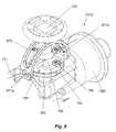
- FIG. 9is an isometric partial cutaway view, illustrating internal components of the catheter control mechanism provided in connection with the handle illustrated in FIG. 7 ;
- FIG. 10is a side partial cutaway view, illustrating of the catheter control mechanism of FIG. 9 ;
- FIG. 11is a longitudinal cross-sectional view illustrating internal components of the catheter control mechanism of FIG. 9 ;
- FIG. 12is a detail cross-sectional view illustrating internal components of the catheter control mechanism of FIG. 9 ;
- FIG. 13is a side view illustrating the internal components of the catheter control mechanism of FIG. 9 ;
- FIG. 14is a side cross-sectional view illustrating the internal components of the catheter control mechanism of FIG. 9 ;
- FIG. 15is a rear view of the internal components of the catheter control mechanism of FIG. 9 ;
- FIG. 16is a bottom view of the internal components of the catheter control mechanism of FIG. 9 ;
- FIG. 17is a top view of the internal components of the catheter control mechanism of FIG. 9 ;
- FIG. 18is a top isometric view of the internal components of the catheter control mechanism of FIG. 9 ;
- FIG. 19is a bottom isometric view of a yoke portion of the catheter control mechanism of FIG. 9 ;
- FIG. 20is a bottom isometric view of a bottom flange portion for engaging the yoke of FIG. 19 with a swivel joint;
- FIG. 21is a top side isometric view illustrating the configuration of a ball portion of the swivel joint of the catheter control mechanism of FIG. 9 ;
- FIG. 22is a front top isometric view illustrating the configuration of the ball portion of the swivel joint of the catheter control mechanism of FIG. 9 ;
- FIG. 23is a front end view of the catheter control mechanism of FIG. 7 ;
- FIG. 24is an isometric view of a screw for connecting a catheter steering wire-engaging element to a yoke portion of the catheter control mechanism of FIG. 9 ;
- FIG. 25is an isometric view of a steering wire-engaging element of the catheter control mechanism of FIG. 9 .
- FIG. 1a steerable catheter lead assembly is shown in FIG. 1 , and designated by reference number 100 .
- the steerable lead assemblyincludes a main handle 110 , main shaft 130 , steerable distal shaft portion 140 and a control handle 120 operatively connected with a control assembly 200 , as best seen in FIGS. 2 and 6 , for example.
- a control assembly 200provided in the main handle 110 of the catheter lead assembly 100 includes at its proximal end, a swivel joint 280 , embodied as a spherical ball joint.
- the swivel joint 280allows for multi-axis movement of the control handle 120 , which in-turn manipulates steering wires 420 a , 420 b , 420 c , 420 d (See FIGS. 4-6 ).
- the swivel joint 280is set off from a control body 260 by a stem 250 .
- the control body 260includes a distal engagement portion 270 for connecting to the shaft 130 , and also facilitates assembly with the main handle 110 , by engaging an inner wall of the main handle 110 , when assembled.
- the stem 250as best seen in FIG. 6 , for example, supports guide pins 615 , among other features, which facilitate manipulation of the steering wires 420 a , 420 b , 420 c , 420 d , the operation of which will be discussed in more detail below.
- the control body 260also includes, at its distal end, respective passages for guiding the steering wires 420 therethrough and into the shaft 130 .
- FIGS. 3-5illustrate a side view, a proximal end view and a longitudinal cross-sectional view of a distal portion 140 of the shaft 130 of catheter lead assembly 100 , respectively.
- a proximal portion of the shaft 130which includes a portion 141 of the shaft 130 proximal the distal portion 140 thereof, is preferably formed of a relatively stiff biocompatible material, including but not limited to a polyether block amide, such as PEBAX®, a fluoropolymer such as polytetrafluoroethylene (e.g. Teflon®), silicone or urethane, for example.
- the material selectedpreferably imparts sufficient rigidity to the shaft 130 , such that insertion of the lead assembly 100 proceeds through the respective anatomical access path without buckling.
- the shaft 130should be sufficiently flexible so as to allow the shaft 130 of the lead assembly 100 to bend sufficiently so to enable it to follow an anatomical pathway, through which the lead assembly 100 is inserted.
- the structure of the shaft 130includes among other features, outer stiff and flexible regions 141 , 143 respectively.
- the material properties of the internal core 410can be selected to correlate to those of the outer region of the shaft 130 , with both flexible and stiff regions. Additionally or alternatively, the structure of selected sections can be configured to be more flexible, such as by providing a thinned or otherwise weakened material area, and/or segmentations with full or partial spaces therebetween, for example.
- the material of the core 410can be continuous in material properties and/or physical configuration and/or the material on the outer portion of the shaft 130 can be continuous in material properties and/or physical configuration.
- the stiff and flexible propertiescan be predominantly the result of the material properties of the core 410 alone, with the outer surface of the shaft 130 being formed of a single material, such as silicone rubber or a urethane material, for example.
- the stiff and flexible propertiescan be predominantly the result of the material properties of the outer surface of the shaft 130 alone, with the core 410 being formed of a single material, for example.
- one or more electrodes 147 , 149can be incorporated into the distal portion 140 of the shaft 130 .
- the proximal electrode 147can be utilized as an anode
- the distal electrode 149as a cathode.
- a fewer or greater number of electrodescan be provided, as required or desired.
- one or more electrodescan be used for sensing, while one or more electrodes can be used for delivering a therapeutic electrical charge, such as for pulsing, ablation or another purpose.
- the illustrated embodimentincludes two concentric helical conductors 431 , 435 , each respectively connected to one of the proximal electrode 147 and distal electrode 149 .
- the helical conductorscan optionally each have substantially the same diameter.
- the first conductor 435is lead out to the proximal electrode 147 and connected thereto in a suitable manner, such as by welding.
- the second conductor 431continues distally to the distal electrode 149 , and is connected thereto in a suitable manner, such as by a weld.
- the second conductor 431is inserted over a reduced diameter proximal portion 148 of the distal electrode 149 to facilitate engagement therewith, while minimizing the diameter and enhancing the structural integrity of the shaft 130 .
- concentric componentsincluding an outer body 401 , an inner core 410 , and a protective tube 437 applied between the core 410 and the conductors 431 , 435 .
- a further inner concentric tube 412can be provided for protecting the conductors 431 , 435 and/or for the purpose of insulating them from further inner concentric components and/or for providing further structural integrity.
- an intervening insulative layercan be provided around, or alternatively between the conductors 431 , 435 , if provided.
- alternate insulation arrangementscan be provided, such as those shown in U.S. Pat. No. 6,978,185 to Osypka and U.S. Pat. No. 7,158,837 to Osypka et al., which patents are incorporated herein by reference in their entirety.
- a plurality of circumferentially spaced steering wires 420 a , 420 b , 420 c , 420 dare provided in channels formed in the core 410 .
- the steering wires 420 a , 420 b , 420 c , 420 dare connected at their distal end to a steering ring 145 in the distal end portion 140 of the shaft 130 .
- the connection therebetweencan be made by any suitable means, including but not limited to welding thereto.
- the steering wires 420 a , 420 b , 420 c , 420 dare connected to the control assembly 200 .
- the control assembly 200includes a swivel joint 280 , which in the illustrated embodiment is a spherical ball joint.
- the swivel joint 280allows for multi-axis movement of the control handle 120 , which is mounted thereon by way of a socket portion 685 thereof.
- control handle 120 and socket 685are also connected to one or more flanges 681 , 683 , which engage the steering wires 420 a , 420 b , 420 c , 420 d , and function as a control yoke for manipulating the steering wires 420 .
- the steering wires 420 a , 420 b , 420 c , 420 dinclude terminations 621 .
- the steering wires 420 a , 420 b , 420 c , 420 dare inserted into radial grooves 684 formed in the proximal flange 683 , and the terminations 621 inhibit the steering wires 420 a , 420 b , 420 c , 420 d from pulling through their designated groove.
- the proximal flange 683is integrally formed with the socket 685 , and is mechanically connected to the distal flange 681 , by a plurality of bolts 687 . Alternative connections can be substituted as desired or required.
- the socket 685can be maintained in position on the ball of the swivel joint 280 by distally directed tension. As illustrated, the distal flange 681 is brought into connection with the proximal flange 683 after the ball 281 is accepted within the socket 685 .
- the distal flange 681can be inserted on the stem 250 from the distal end thereof, or alternatively, can be provided in two or more split parts, and separately connected to the proximal flange 683 to secure the control handle 120 , socket 685 and the proximal and distal flanges 683 , 681 to the ball 284 of the swivel joint 280 .
- an inner diameter of the distal flange 681is selected to be between an outer diameter of the stem 250 and an outer diameter of the ball 284 of swivel joint 280 , to maintain secure connection therebetween and to inhibit removal therefrom.
- the steering wires 420 a , 420 b , 420 c , 420 dare provided, and spaced circumferentially respectively separated by about 90 degrees.
- wire 420 bis referred to herein as the “top” steering wire
- wire 420 dis the “bottom” steering wire
- wire 420 ais the “right” steering wire
- wire 420 cas the “left” steering wire.
- the top and bottom steering wires 420 b , 420 dextend through respective slots 686 formed in the distal flange 681 and are held therein by the respective steering wire terminations 621 .
- the control handle 120is illustrated in FIG. 6 in a right position, but when in a neutral position, the top slot 686 aligns with a neutral position of the top steering wire 420 b , while the bottom steering wire 420 d is accepted in a similar arrangement in an opposed slot.
- the left and right steering wires 420 c , 420 aare engaged by the respective slots 684 , and extend through slots 682 , which are, as illustrated, preferably rounded or include other adaptations to minimize kinking and/or chafing of the left and right steering wires 420 c , 420 a extending therethrough.
- the left and right steering wires 420 c , 420 aextend over laterally (also radially) extending pins 615 . Rotational movement of the control handle 120 toward the left or right side, with respect to the body, results in increased tension applied to the steering wire 420 c , 420 a on the same side. As such movement (e.g.
- the opposite steering wire 420 a , 420 c(e.g. left steering wire 420 c ) rises above its respective pin 615 , from a neutral position.
- the tension applied to the wire corresponding to the intended directione.g. right steering wire 420 a
- the tension applied to the wire corresponding to the intended directionis greater and compensates for any tension applied to the opposite steering wire (e.g. left steering wire 420 c ).
- the tension applied to the steering wires 420 a - dextends through the shaft 130 to the steering ring 145 , which responds by moving in the respective direction, and along with it, the distal end portion 140 of the shaft 130 .
- most bendingoccurs in the flexible material region 143 between the stiff material region 141 and the steering ring 145 (e.g. FIG. 3 ), however variations of this arrangement are conceived.
- Upward and downward movement of the distal end portion 140is effected by selectively tensioning the respective steering wire 420 c , 420 d .
- the control handle 120is moved backward (proximally) or forward (distally), pivoting on the swivel joint 280 , to achieve the desired response of the shaft 140 .
- Combined directional movementscan be effected by tensioning multiple adjacent steering wires.
- top and right steering wires 420 b , 420 dcan be tensioned to effect upward and rightward directed movement of the distal end 140 of the shaft 130 by moving the control handle 120 to the right and backward (proximally).
- the pins 615can be provided at about the center line of the stem 250 , or alternatively can be offset therefrom. As set forth above, the displacement caused by the pins 615 causes increased tension in respective steering wires, as compared with the opposite steering wires. Alternatively, the pins can be offset from the central axis by set distance, such that in a neutral position, the left and right steering wires 420 a , 420 c are deflected by the pins 615 . In such an arrangement, tension is applied to the desired steering wire as it is forced to deflect further, and tension in the opposite steering wire is relaxed, as it is allowed to straighten. In such an arrangement, the pins 615 on both sides of the stem 250 in the embodiment of FIG. 6 are arranged somewhat above the central axis of the stem 250 , such that each steering wire is deflected by running across an upper surface of the respective pin 615 , as is illustrated.
- inserts 415can be provided in the core 410 , corresponding with each steering wire 420 .
- the insertscan serve to protect the core material and/or the steering wires 420 from abrasion due to relative movement therebetween.
- the inserts 415can be provided along the length of the catheter, or alternatively can be provided only at the proximal end thereof such that movement due to manipulation of the steering wires 420 does not adversely affect the integrity of the material of the core 410 .
- the core 410 of the shaft 130can be provided with a central lumen 429 , which remains open.
- the lumen 429can be adapted to hold an internal rigidifying member, such as an obturator or the like, to facilitate insertion of the catheter 100 through a patient's vein or other anatomical pathway.
- the lumen 429can be adapted to deliver medicaments to a surgical site, through one or more apertures that can be defined through the wall of the distal end portion 140 of the catheter shaft 130 .
- the shaft 130can be provided without a hollow lumen.
- any suitable biocompatible materialscan be used for the construction of devices in accordance with the invention.
- the material of the core 410is selected from one or more of polyether block amide, such as PEBAX®, a fluoropolymer such as polytetrafluoroethylene (e.g. Teflon®), silicone or urethane.
- the materials used for the outer surface components of the shaft 130can also be selected from this group of materials.
- the electrodes 147 , 149can be made of any suitable biocompatible electrically conductive material, such as a metal alloy, for example a stainless steel.
- the steering wires 420can be formed of a suitable polymeric or metal material, which is preferably compatible with the material used to form the steering ring 145 to facilitate attachment thereto.
- the material selected for the steering wires 420 and the steering ring 145 in accordance with one aspect of the inventionis a weldable metal material, such as a stainless steel alloy or a shape memory alloy, such as a nickel-titanium alloy (e.g. Nitinol), for example.
- the electrical conductors 431 , 435can be any suitable material including but not limited to stranded stainless steel, copper, drawn filled tube (DFT) formed of any suitable materials or other conductors, and each conductor can be independently insulated, if desired.
- DFTdrawn filled tube
- FIG. 7A further catheter control mechanism constructed in accordance with the invention is shown in FIG. 7 , and designated by reference number 710 .
- the catheter control mechanism 710includes a handle 711 , a control lever 720 , a gaiter 721 for sealing between the handle 711 and the control lever 720 , an upper grip 712 and lower grip 713 to facilitate secure handling by a user, such as a physician.
- control lever 720is connected to a swivel joint 780 , including a yoke 782 , on which a plurality of catheter steering wire-engaging elements 795 are orthogonally arranged.
- the lever 720is supported from below by the yoke 782 , and is optionally supported in the upper portion by a stabilizer 970 .
- the stabilizer 970is pivotably connected to the handle 711 at its lower ends, as indicated by reference numbers 971 a and 971 b.
- the swivel joint 780also includes a ball portion 784 that supports the yoke 782 , and which in-turn is supported by a stem 1250 , extending from a proximal end cap 1360 , secured to the handle 711 .
- the yoke 782is secured to the ball portion 784 by way of an integral upper flange 783 and separate lower flange portions 781 , which are secured thereto from below and which, in conjunction with the yoke 782 , securely captures the ball portion 784 .
- Catheter steering wires 1296are connected to the steering wire engaging elements 795 at one end, and are routed downward into corresponding orthogonally arranged apertures 1251 , 1252 , 1253 , 1254 formed in the stem 1250 , through a passage 1256 connected therethrough and through the front end cap 1360 of the control mechanism 710 , where the control mechanism 710 engages a catheter (see FIG. 23 ).
- the passage 1256 formed in the stem 1250is optionally provided with a lower access opening 1258 and an end access opening 1259 to facilitate threading of the catheter steering wires 1296 through the stem 1250 and to the steering wire engaging elements 795 .
- the swivel joint 780and particularly the ball portion 784 and the control yoke 782 , are configured for mutually exclusive orthogonal movement, the handle 711 being restrained to either forward-backward movement or left-right movement at any one moment.
- the yoke 782includes, on its bottom surface, yoke guides 785 extending therefrom. The guides 785 are provided in a colinear arrangement corresponding to a longitudinal channel 786 formed in the ball portion 784 .
- the guides 785individually align with lateral channels 787 a , 787 b formed in the ball portion 784 , permitting side-to-side movement of the yoke 782 with respect to the ball portion 784 .
- the configuration of the channels 786 , 787 a , 787 b formed in the ball portion 784permits only exclusive side-to-side (lateral/circumferential) or forward-backward (longitudinal) movement of the yoke 782 and handle 720 at any moment. Such an arrangement advantageously guides the user more precisely in each respective motion.
- the side-to-side (lateral/circumferential) movement of the control lever 720causes the yoke 782 to pull upward on the respective one of the side steering wire engaging elements 795 , to which catheter steering wires 1296 are attached, and forward-backward (longitudinal) movement of the control lever 720 causes the yoke 782 to pull upward on the respective one of the front or back steering wire engaging elements 795 .
- tensionis applied to one of the steering wires 1296 which is carried through the attached catheter, effecting bending thereof, typically at the distal end portion of the catheter, as described above, but depending on the configuration thereof.
- the catheter steering wires 1296can be configured and connected to the yoke 782 such that left-directed motion of the lever 720 applies tension to a left steering wire 1296 , effecting left bending of the catheter, and so-on for each of the orthogonal directions.
- tension applied to the steering wires 1296can be adjusted by adjusting the relative spacing between the upper flange 783 and the steering wire engaging elements 795 , by adjusting the screw 797 therebetween, a detail view of which is shown in FIG. 24 .
Landscapes
- Health & Medical Sciences (AREA)
- Life Sciences & Earth Sciences (AREA)
- Engineering & Computer Science (AREA)
- Anesthesiology (AREA)
- Biophysics (AREA)
- Pulmonology (AREA)
- Biomedical Technology (AREA)
- Heart & Thoracic Surgery (AREA)
- Hematology (AREA)
- Animal Behavior & Ethology (AREA)
- General Health & Medical Sciences (AREA)
- Public Health (AREA)
- Veterinary Medicine (AREA)
- Mechanical Engineering (AREA)
- Media Introduction/Drainage Providing Device (AREA)
Abstract
Description
Claims (7)
Priority Applications (1)
| Application Number | Priority Date | Filing Date | Title |
|---|---|---|---|
| US12/603,584US9061120B2 (en) | 2004-08-05 | 2009-10-21 | Catheter control mechanism and steerable catheter |
Applications Claiming Priority (5)
| Application Number | Priority Date | Filing Date | Title |
|---|---|---|---|
| US10/911,975US7197361B2 (en) | 2003-08-08 | 2004-08-05 | Cardiac lead with anodic electrode assembly having dual support hulls |
| US11/261,304US20060095107A1 (en) | 2004-10-28 | 2005-10-28 | Flexible lead body for implantable stimulation leads |
| US10722708P | 2008-10-21 | 2008-10-21 | |
| US17840909P | 2009-05-14 | 2009-05-14 | |
| US12/603,584US9061120B2 (en) | 2004-08-05 | 2009-10-21 | Catheter control mechanism and steerable catheter |
Publications (2)
| Publication Number | Publication Date |
|---|---|
| US20100106141A1 US20100106141A1 (en) | 2010-04-29 |
| US9061120B2true US9061120B2 (en) | 2015-06-23 |
Family
ID=42118190
Family Applications (1)
| Application Number | Title | Priority Date | Filing Date |
|---|---|---|---|
| US12/603,584Active2032-12-19US9061120B2 (en) | 2004-08-05 | 2009-10-21 | Catheter control mechanism and steerable catheter |
Country Status (1)
| Country | Link |
|---|---|
| US (1) | US9061120B2 (en) |
Cited By (19)
| Publication number | Priority date | Publication date | Assignee | Title |
|---|---|---|---|---|
| WO2019213552A1 (en)* | 2018-05-03 | 2019-11-07 | Thermedical , Inc. | Devices and methods for selectively deploying catheter instruments |
| US10603488B2 (en) | 2017-02-10 | 2020-03-31 | Oscor Inc. | Implantable medical devices having diamagnetic conductors and contacts |
| US10881443B2 (en) | 2011-04-12 | 2021-01-05 | Thermedical, Inc. | Devices and methods for shaping therapy in fluid enhanced ablation |
| US10912644B2 (en) | 2018-10-05 | 2021-02-09 | Shifamed Holdings, Llc | Prosthetic cardiac valve devices, systems, and methods |
| US11013555B2 (en) | 2016-08-11 | 2021-05-25 | Thermedical, Inc. | Devices and methods for delivering fluid to tissue during ablation therapy |
| US11147635B1 (en) | 2020-06-19 | 2021-10-19 | Remedy Robotics, Inc. | Systems and methods for guidance of intraluminal devices within the vasculature |
| USD940307S1 (en)* | 2020-06-11 | 2022-01-04 | Oscor Inc. | Steerable catheter handle |
| USD940306S1 (en)* | 2020-06-11 | 2022-01-04 | Oscor Inc. | Steerable catheter handle |
| US11471282B2 (en) | 2019-03-19 | 2022-10-18 | Shifamed Holdings, Llc | Prosthetic cardiac valve devices, systems, and methods |
| US11690683B2 (en) | 2021-07-01 | 2023-07-04 | Remedy Robotics, Inc | Vision-based position and orientation determination for endovascular tools |
| US11707332B2 (en) | 2021-07-01 | 2023-07-25 | Remedy Robotics, Inc. | Image space control for endovascular tools |
| US11833034B2 (en) | 2016-01-13 | 2023-12-05 | Shifamed Holdings, Llc | Prosthetic cardiac valve devices, systems, and methods |
| US11918277B2 (en) | 2018-07-16 | 2024-03-05 | Thermedical, Inc. | Inferred maximum temperature monitoring for irrigated ablation therapy |
| US12053371B2 (en) | 2020-08-31 | 2024-08-06 | Shifamed Holdings, Llc | Prosthetic valve delivery system |
| US12121307B2 (en) | 2021-07-01 | 2024-10-22 | Remedy Robotics, Inc. | Vision-based position and orientation determination for endovascular tools |
| US12201521B2 (en) | 2021-03-22 | 2025-01-21 | Shifamed Holdings, Llc | Anchor position verification for prosthetic cardiac valve devices |
| US12290456B2 (en) | 2018-08-21 | 2025-05-06 | Shifamed Holdings, Llc | Prosthetic cardiac valve devices, systems, and methods |
| US12329635B2 (en) | 2020-12-04 | 2025-06-17 | Shifamed Holdings, Llc | Flared prosthetic cardiac valve delivery devices and systems |
| US12403008B2 (en) | 2018-10-19 | 2025-09-02 | Shifamed Holdings, Llc | Adjustable medical device |
Families Citing this family (99)
| Publication number | Priority date | Publication date | Assignee | Title |
|---|---|---|---|---|
| US8608797B2 (en) | 2005-03-17 | 2013-12-17 | Valtech Cardio Ltd. | Mitral valve treatment techniques |
| US11259924B2 (en) | 2006-12-05 | 2022-03-01 | Valtech Cardio Ltd. | Implantation of repair devices in the heart |
| US9883943B2 (en) | 2006-12-05 | 2018-02-06 | Valtech Cardio, Ltd. | Implantation of repair devices in the heart |
| US11660190B2 (en) | 2007-03-13 | 2023-05-30 | Edwards Lifesciences Corporation | Tissue anchors, systems and methods, and devices |
| US8382829B1 (en) | 2008-03-10 | 2013-02-26 | Mitralign, Inc. | Method to reduce mitral regurgitation by cinching the commissure of the mitral valve |
| US8652202B2 (en) | 2008-08-22 | 2014-02-18 | Edwards Lifesciences Corporation | Prosthetic heart valve and delivery apparatus |
| US8241351B2 (en) | 2008-12-22 | 2012-08-14 | Valtech Cardio, Ltd. | Adjustable partial annuloplasty ring and mechanism therefor |
| US10517719B2 (en) | 2008-12-22 | 2019-12-31 | Valtech Cardio, Ltd. | Implantation of repair devices in the heart |
| US8911494B2 (en) | 2009-05-04 | 2014-12-16 | Valtech Cardio, Ltd. | Deployment techniques for annuloplasty ring |
| US8715342B2 (en) | 2009-05-07 | 2014-05-06 | Valtech Cardio, Ltd. | Annuloplasty ring with intra-ring anchoring |
| WO2010073246A2 (en) | 2008-12-22 | 2010-07-01 | Valtech Cardio, Ltd. | Adjustable annuloplasty devices and adjustment mechanisms therefor |
| US8808345B2 (en) | 2008-12-31 | 2014-08-19 | Medtronic Ardian Luxembourg S.A.R.L. | Handle assemblies for intravascular treatment devices and associated systems and methods |
| US8353956B2 (en) | 2009-02-17 | 2013-01-15 | Valtech Cardio, Ltd. | Actively-engageable movement-restriction mechanism for use with an annuloplasty structure |
| US9968452B2 (en) | 2009-05-04 | 2018-05-15 | Valtech Cardio, Ltd. | Annuloplasty ring delivery cathethers |
| US10098737B2 (en) | 2009-10-29 | 2018-10-16 | Valtech Cardio, Ltd. | Tissue anchor for annuloplasty device |
| US9180007B2 (en) | 2009-10-29 | 2015-11-10 | Valtech Cardio, Ltd. | Apparatus and method for guide-wire based advancement of an adjustable implant |
| US8734467B2 (en) | 2009-12-02 | 2014-05-27 | Valtech Cardio, Ltd. | Delivery tool for implantation of spool assembly coupled to a helical anchor |
| US8449599B2 (en) | 2009-12-04 | 2013-05-28 | Edwards Lifesciences Corporation | Prosthetic valve for replacing mitral valve |
| EP3345573B1 (en) | 2011-06-23 | 2020-01-29 | Valtech Cardio, Ltd. | Closure element for use with annuloplasty structure |
| US10792152B2 (en) | 2011-06-23 | 2020-10-06 | Valtech Cardio, Ltd. | Closed band for percutaneous annuloplasty |
| WO2013016275A1 (en) | 2011-07-22 | 2013-01-31 | Cook Medical Technologies Llc | Irrigation devices adapted to be used with a light source for the identification and treatment of bodily passages |
| US8858623B2 (en) | 2011-11-04 | 2014-10-14 | Valtech Cardio, Ltd. | Implant having multiple rotational assemblies |
| EP3656434B1 (en) | 2011-11-08 | 2021-10-20 | Valtech Cardio, Ltd. | Controlled steering functionality for implant-delivery tool |
| US9375138B2 (en) | 2011-11-25 | 2016-06-28 | Cook Medical Technologies Llc | Steerable guide member and catheter |
| EP2881083B1 (en) | 2011-12-12 | 2017-03-22 | David Alon | Heart valve repair device |
| US9216018B2 (en) | 2012-09-29 | 2015-12-22 | Mitralign, Inc. | Plication lock delivery system and method of use thereof |
| WO2014064694A2 (en) | 2012-10-23 | 2014-05-01 | Valtech Cardio, Ltd. | Controlled steering functionality for implant-delivery tool |
| EP2911593B1 (en) | 2012-10-23 | 2020-03-25 | Valtech Cardio, Ltd. | Percutaneous tissue anchor techniques |
| WO2014087402A1 (en) | 2012-12-06 | 2014-06-12 | Valtech Cardio, Ltd. | Techniques for guide-wire based advancement of a tool |
| US9439763B2 (en) | 2013-02-04 | 2016-09-13 | Edwards Lifesciences Corporation | Prosthetic valve for replacing mitral valve |
| EP2961351B1 (en) | 2013-02-26 | 2018-11-28 | Mitralign, Inc. | Devices for percutaneous tricuspid valve repair |
| US10449333B2 (en) | 2013-03-14 | 2019-10-22 | Valtech Cardio, Ltd. | Guidewire feeder |
| CN105283214B (en) | 2013-03-15 | 2018-10-16 | 北京泰德制药股份有限公司 | Translate conduit, system and its application method |
| US9913684B2 (en) | 2013-08-23 | 2018-03-13 | Oscor Inc. | Steerable ablation catheter for renal denervation |
| US9907570B2 (en) | 2013-08-23 | 2018-03-06 | Oscor Inc. | Steerable medical devices |
| US10070857B2 (en) | 2013-08-31 | 2018-09-11 | Mitralign, Inc. | Devices and methods for locating and implanting tissue anchors at mitral valve commissure |
| WO2015059699A2 (en) | 2013-10-23 | 2015-04-30 | Valtech Cardio, Ltd. | Anchor magazine |
| US9622863B2 (en) | 2013-11-22 | 2017-04-18 | Edwards Lifesciences Corporation | Aortic insufficiency repair device and method |
| US9610162B2 (en) | 2013-12-26 | 2017-04-04 | Valtech Cardio, Ltd. | Implantation of flexible implant |
| US9937323B2 (en) | 2014-02-28 | 2018-04-10 | Cook Medical Technologies Llc | Deflectable catheters, systems, and methods for the visualization and treatment of bodily passages |
| USD782037S1 (en) | 2014-08-08 | 2017-03-21 | Oscor Inc. | Steerable guiding catheter handle |
| EP3922213A1 (en) | 2014-10-14 | 2021-12-15 | Valtech Cardio, Ltd. | Leaflet-restraining techniques |
| WO2016090308A1 (en) | 2014-12-04 | 2016-06-09 | Edwards Lifesciences Corporation | Percutaneous clip for repairing a heart valve |
| US20160256269A1 (en) | 2015-03-05 | 2016-09-08 | Mitralign, Inc. | Devices for treating paravalvular leakage and methods use thereof |
| CN107847320B (en) | 2015-04-30 | 2020-03-17 | 瓦尔泰克卡迪欧有限公司 | Valvuloplasty techniques |
| EP3294219B1 (en) | 2015-05-14 | 2020-05-13 | Edwards Lifesciences Corporation | Heart valve sealing devices and delivery devices therefor |
| US10828160B2 (en) | 2015-12-30 | 2020-11-10 | Edwards Lifesciences Corporation | System and method for reducing tricuspid regurgitation |
| US11219746B2 (en) | 2016-03-21 | 2022-01-11 | Edwards Lifesciences Corporation | Multi-direction steerable handles for steering catheters |
| US10799676B2 (en)* | 2016-03-21 | 2020-10-13 | Edwards Lifesciences Corporation | Multi-direction steerable handles for steering catheters |
| US10799675B2 (en) | 2016-03-21 | 2020-10-13 | Edwards Lifesciences Corporation | Cam controlled multi-direction steerable handles |
| US10799677B2 (en) | 2016-03-21 | 2020-10-13 | Edwards Lifesciences Corporation | Multi-direction steerable handles for steering catheters |
| US10835714B2 (en) | 2016-03-21 | 2020-11-17 | Edwards Lifesciences Corporation | Multi-direction steerable handles for steering catheters |
| US10702274B2 (en) | 2016-05-26 | 2020-07-07 | Edwards Lifesciences Corporation | Method and system for closing left atrial appendage |
| US10973638B2 (en) | 2016-07-07 | 2021-04-13 | Edwards Lifesciences Corporation | Device and method for treating vascular insufficiency |
| GB201611910D0 (en) | 2016-07-08 | 2016-08-24 | Valtech Cardio Ltd | Adjustable annuloplasty device with alternating peaks and troughs |
| US10653862B2 (en) | 2016-11-07 | 2020-05-19 | Edwards Lifesciences Corporation | Apparatus for the introduction and manipulation of multiple telescoping catheters |
| US10905554B2 (en) | 2017-01-05 | 2021-02-02 | Edwards Lifesciences Corporation | Heart valve coaptation device |
| EP4613214A2 (en) | 2017-04-18 | 2025-09-10 | Edwards Lifesciences Corporation | Heart valve sealing devices and delivery devices therefor |
| US11224511B2 (en) | 2017-04-18 | 2022-01-18 | Edwards Lifesciences Corporation | Heart valve sealing devices and delivery devices therefor |
| US11045627B2 (en) | 2017-04-18 | 2021-06-29 | Edwards Lifesciences Corporation | Catheter system with linear actuation control mechanism |
| US10799312B2 (en) | 2017-04-28 | 2020-10-13 | Edwards Lifesciences Corporation | Medical device stabilizing apparatus and method of use |
| US10959846B2 (en) | 2017-05-10 | 2021-03-30 | Edwards Lifesciences Corporation | Mitral valve spacer device |
| US11051940B2 (en) | 2017-09-07 | 2021-07-06 | Edwards Lifesciences Corporation | Prosthetic spacer device for heart valve |
| US11065117B2 (en) | 2017-09-08 | 2021-07-20 | Edwards Lifesciences Corporation | Axisymmetric adjustable device for treating mitral regurgitation |
| US11040174B2 (en) | 2017-09-19 | 2021-06-22 | Edwards Lifesciences Corporation | Multi-direction steerable handles for steering catheters |
| US10835221B2 (en) | 2017-11-02 | 2020-11-17 | Valtech Cardio, Ltd. | Implant-cinching devices and systems |
| US11135062B2 (en) | 2017-11-20 | 2021-10-05 | Valtech Cardio Ltd. | Cinching of dilated heart muscle |
| US10238493B1 (en) | 2018-01-09 | 2019-03-26 | Edwards Lifesciences Corporation | Native valve repair devices and procedures |
| US10973639B2 (en) | 2018-01-09 | 2021-04-13 | Edwards Lifesciences Corporation | Native valve repair devices and procedures |
| US10231837B1 (en) | 2018-01-09 | 2019-03-19 | Edwards Lifesciences Corporation | Native valve repair devices and procedures |
| US10105222B1 (en) | 2018-01-09 | 2018-10-23 | Edwards Lifesciences Corporation | Native valve repair devices and procedures |
| US10159570B1 (en) | 2018-01-09 | 2018-12-25 | Edwards Lifesciences Corporation | Native valve repair devices and procedures |
| FI3964175T3 (en) | 2018-01-09 | 2024-12-03 | Edwards Lifesciences Corp | Native valve repair devices |
| US10123873B1 (en) | 2018-01-09 | 2018-11-13 | Edwards Lifesciences Corporation | Native valve repair devices and procedures |
| US10111751B1 (en) | 2018-01-09 | 2018-10-30 | Edwards Lifesciences Corporation | Native valve repair devices and procedures |
| US10136993B1 (en) | 2018-01-09 | 2018-11-27 | Edwards Lifesciences Corporation | Native valve repair devices and procedures |
| US10245144B1 (en) | 2018-01-09 | 2019-04-02 | Edwards Lifesciences Corporation | Native valve repair devices and procedures |
| US10076415B1 (en) | 2018-01-09 | 2018-09-18 | Edwards Lifesciences Corporation | Native valve repair devices and procedures |
| EP3510914A1 (en)* | 2018-01-15 | 2019-07-17 | Koninklijke Philips N.V. | Device with bendable distal portion and system actuating the distal portion of the device |
| CN116531147A (en) | 2018-01-24 | 2023-08-04 | 爱德华兹生命科学创新(以色列)有限公司 | Contraction of annuloplasty structures |
| EP4248904A3 (en) | 2018-01-26 | 2023-11-29 | Edwards Lifesciences Innovation (Israel) Ltd. | Techniques for facilitating heart valve tethering and chord replacement |
| US20190255292A1 (en)* | 2018-02-16 | 2019-08-22 | Oscor Inc. | Deflectable sheath with inflatable balloon |
| US11389297B2 (en) | 2018-04-12 | 2022-07-19 | Edwards Lifesciences Corporation | Mitral valve spacer device |
| US11207181B2 (en) | 2018-04-18 | 2021-12-28 | Edwards Lifesciences Corporation | Heart valve sealing devices and delivery devices therefor |
| EP3820406B1 (en) | 2018-07-12 | 2023-12-20 | Edwards Lifesciences Innovation (Israel) Ltd. | Annuloplasty systems and locking tools therefor |
| US10945844B2 (en) | 2018-10-10 | 2021-03-16 | Edwards Lifesciences Corporation | Heart valve sealing devices and delivery devices therefor |
| CN113226223A (en) | 2018-11-20 | 2021-08-06 | 爱德华兹生命科学公司 | Deployment tools and methods for delivering devices to native heart valves |
| CA3118988A1 (en) | 2018-11-21 | 2020-05-28 | Edwards Lifesciences Corporation | Heart valve sealing devices, delivery devices therefor, and retrieval devices |
| CR20210312A (en) | 2018-11-29 | 2021-09-14 | Edwards Lifesciences Corp | Catheterization method and apparatus |
| ES2969252T3 (en) | 2019-02-14 | 2024-05-17 | Edwards Lifesciences Corp | Heart valve sealing devices and delivery devices therefor |
| SG11202112651QA (en) | 2019-05-29 | 2021-12-30 | Valtech Cardio Ltd | Tissue anchor handling systems and methods |
| WO2020247386A1 (en)* | 2019-06-02 | 2020-12-10 | Wolf Technical Services, Inc. | Tube introducer intubation device |
| US12364606B2 (en) | 2019-07-23 | 2025-07-22 | Edwards Lifesciences Innovation (Israel) Ltd. | Fluoroscopic visualization of heart valve anatomy |
| JP2022546160A (en) | 2019-08-30 | 2022-11-04 | エドワーズ ライフサイエンシーズ イノベーション (イスラエル) リミテッド | Anchor channel tip |
| EP4034042A1 (en) | 2019-09-25 | 2022-08-03 | Cardiac Implants LLC | Cardiac valve annulus reduction system |
| EP4193934A1 (en) | 2019-10-29 | 2023-06-14 | Edwards Lifesciences Innovation (Israel) Ltd. | Annuloplasty and tissue anchor technologies |
| US12023247B2 (en) | 2020-05-20 | 2024-07-02 | Edwards Lifesciences Corporation | Reducing the diameter of a cardiac valve annulus with independent control over each of the anchors that are launched into the annulus |
| CA3182316A1 (en) | 2020-06-19 | 2021-12-23 | Edwards Lifesciences Innovation (Israel) Ltd. | Self-stopping tissue anchors |
| USD1071198S1 (en) | 2023-06-28 | 2025-04-15 | Edwards Lifesciences Corporation | Cradle |
Citations (8)
| Publication number | Priority date | Publication date | Assignee | Title |
|---|---|---|---|---|
| US3605725A (en)* | 1968-08-07 | 1971-09-20 | Medi Tech Inc | Controlled motion devices |
| US4456017A (en)* | 1982-11-22 | 1984-06-26 | Cordis Corporation | Coil spring guide with deflectable tip |
| US5037391A (en)* | 1989-01-09 | 1991-08-06 | Pilot Cardiovascular Systems, Inc. | Steerable angioplasty device |
| US5676653A (en)* | 1995-06-27 | 1997-10-14 | Arrow International Investment Corp. | Kink-resistant steerable catheter assembly |
| US20050060013A1 (en) | 2003-08-08 | 2005-03-17 | Van Den Nieuwenhof Ronald A. | Cardiac lead with anodic electrode assembly having dual support hulls |
| US6978185B2 (en) | 2001-11-09 | 2005-12-20 | Oscor Inc. | Multifilar conductor for cardiac leads |
| US20060095107A1 (en) | 2004-10-28 | 2006-05-04 | Osypka Thomas P | Flexible lead body for implantable stimulation leads |
| US7158837B2 (en) | 2002-07-10 | 2007-01-02 | Oscor Inc. | Low profile cardiac leads |
- 2009
- 2009-10-21USUS12/603,584patent/US9061120B2/enactiveActive
Patent Citations (8)
| Publication number | Priority date | Publication date | Assignee | Title |
|---|---|---|---|---|
| US3605725A (en)* | 1968-08-07 | 1971-09-20 | Medi Tech Inc | Controlled motion devices |
| US4456017A (en)* | 1982-11-22 | 1984-06-26 | Cordis Corporation | Coil spring guide with deflectable tip |
| US5037391A (en)* | 1989-01-09 | 1991-08-06 | Pilot Cardiovascular Systems, Inc. | Steerable angioplasty device |
| US5676653A (en)* | 1995-06-27 | 1997-10-14 | Arrow International Investment Corp. | Kink-resistant steerable catheter assembly |
| US6978185B2 (en) | 2001-11-09 | 2005-12-20 | Oscor Inc. | Multifilar conductor for cardiac leads |
| US7158837B2 (en) | 2002-07-10 | 2007-01-02 | Oscor Inc. | Low profile cardiac leads |
| US20050060013A1 (en) | 2003-08-08 | 2005-03-17 | Van Den Nieuwenhof Ronald A. | Cardiac lead with anodic electrode assembly having dual support hulls |
| US20060095107A1 (en) | 2004-10-28 | 2006-05-04 | Osypka Thomas P | Flexible lead body for implantable stimulation leads |
Non-Patent Citations (1)
| Title |
|---|
| Nzayinambaho, K., et al., "Radiofrequency Ablation for Supraventricular Tachyarrhythmias," Cardiovascular Center, O.L.V. Hospital, Aalst, Belgium, vol. 3, No. 2, 1993. |
Cited By (34)
| Publication number | Priority date | Publication date | Assignee | Title |
|---|---|---|---|---|
| US11950829B2 (en) | 2011-04-12 | 2024-04-09 | Thermedical, Inc. | Methods and devices for use of degassed fluids with fluid enhanced ablation devices |
| US10881443B2 (en) | 2011-04-12 | 2021-01-05 | Thermedical, Inc. | Devices and methods for shaping therapy in fluid enhanced ablation |
| US11135000B2 (en) | 2011-04-12 | 2021-10-05 | Thermedical, Inc. | Methods and devices for use of degassed fluids with fluid enhanced ablation devices |
| US11583330B2 (en) | 2011-04-12 | 2023-02-21 | Thermedical, Inc. | Devices and methods for remote temperature monitoring in fluid enhanced ablation therapy |
| US11871979B2 (en) | 2011-04-12 | 2024-01-16 | Thermedical, Inc. | Methods and devices for controlling ablation therapy |
| US11833034B2 (en) | 2016-01-13 | 2023-12-05 | Shifamed Holdings, Llc | Prosthetic cardiac valve devices, systems, and methods |
| US12310651B2 (en) | 2016-08-11 | 2025-05-27 | Thermedical, Inc. | Devices and methods for delivering fluid to tissue during ablation therapy |
| US11013555B2 (en) | 2016-08-11 | 2021-05-25 | Thermedical, Inc. | Devices and methods for delivering fluid to tissue during ablation therapy |
| US10603488B2 (en) | 2017-02-10 | 2020-03-31 | Oscor Inc. | Implantable medical devices having diamagnetic conductors and contacts |
| US11083871B2 (en) | 2018-05-03 | 2021-08-10 | Thermedical, Inc. | Selectively deployable catheter ablation devices |
| WO2019213552A1 (en)* | 2018-05-03 | 2019-11-07 | Thermedical , Inc. | Devices and methods for selectively deploying catheter instruments |
| US11918277B2 (en) | 2018-07-16 | 2024-03-05 | Thermedical, Inc. | Inferred maximum temperature monitoring for irrigated ablation therapy |
| US12290456B2 (en) | 2018-08-21 | 2025-05-06 | Shifamed Holdings, Llc | Prosthetic cardiac valve devices, systems, and methods |
| US11986389B2 (en) | 2018-10-05 | 2024-05-21 | Shifamed Holdings, Llc | Prosthetic cardiac valve devices, systems, and methods |
| US12419743B2 (en) | 2018-10-05 | 2025-09-23 | Shifamed Holdings, Llc | Prosthetic cardiac valve devices, systems, and methods |
| US11672657B2 (en) | 2018-10-05 | 2023-06-13 | Shifamed Holdings, Llc | Prosthetic cardiac valve devices, systems, and methods |
| US10912644B2 (en) | 2018-10-05 | 2021-02-09 | Shifamed Holdings, Llc | Prosthetic cardiac valve devices, systems, and methods |
| US12403008B2 (en) | 2018-10-19 | 2025-09-02 | Shifamed Holdings, Llc | Adjustable medical device |
| US11471282B2 (en) | 2019-03-19 | 2022-10-18 | Shifamed Holdings, Llc | Prosthetic cardiac valve devices, systems, and methods |
| USD940306S1 (en)* | 2020-06-11 | 2022-01-04 | Oscor Inc. | Steerable catheter handle |
| USD940307S1 (en)* | 2020-06-11 | 2022-01-04 | Oscor Inc. | Steerable catheter handle |
| US11154366B1 (en) | 2020-06-19 | 2021-10-26 | Remedy Robotics, Inc. | Systems and methods for guidance of intraluminal devices within the vasculature |
| US11229488B2 (en) | 2020-06-19 | 2022-01-25 | Remedy Robotics, Inc. | Systems and methods for guidance of intraluminal devices within the vasculature |
| US11197725B1 (en) | 2020-06-19 | 2021-12-14 | Remedy Robotics, Inc. | Systems and methods for guidance of intraluminal devices within the vasculature |
| US11779406B2 (en) | 2020-06-19 | 2023-10-10 | Remedy Robotics, Inc. | Systems and methods for guidance of intraluminal devices within the vasculature |
| US12193764B2 (en) | 2020-06-19 | 2025-01-14 | Remedy Robotics, Inc. | Systems and methods for guidance of intraluminal devices within the vasculature |
| US11147635B1 (en) | 2020-06-19 | 2021-10-19 | Remedy Robotics, Inc. | Systems and methods for guidance of intraluminal devices within the vasculature |
| US11246667B2 (en) | 2020-06-19 | 2022-02-15 | Remedy Robotics, Inc. | Systems and methods for guidance of intraluminal devices within the vasculature |
| US12053371B2 (en) | 2020-08-31 | 2024-08-06 | Shifamed Holdings, Llc | Prosthetic valve delivery system |
| US12329635B2 (en) | 2020-12-04 | 2025-06-17 | Shifamed Holdings, Llc | Flared prosthetic cardiac valve delivery devices and systems |
| US12201521B2 (en) | 2021-03-22 | 2025-01-21 | Shifamed Holdings, Llc | Anchor position verification for prosthetic cardiac valve devices |
| US12121307B2 (en) | 2021-07-01 | 2024-10-22 | Remedy Robotics, Inc. | Vision-based position and orientation determination for endovascular tools |
| US11707332B2 (en) | 2021-07-01 | 2023-07-25 | Remedy Robotics, Inc. | Image space control for endovascular tools |
| US11690683B2 (en) | 2021-07-01 | 2023-07-04 | Remedy Robotics, Inc | Vision-based position and orientation determination for endovascular tools |
Also Published As
| Publication number | Publication date |
|---|---|
| US20100106141A1 (en) | 2010-04-29 |
Similar Documents
| Publication | Publication Date | Title |
|---|---|---|
| US9061120B2 (en) | Catheter control mechanism and steerable catheter | |
| US20210161472A1 (en) | Basket for a multi-electrode array catheter | |
| US7606609B2 (en) | Devices and methods for cardiac mapping of an annular region | |
| US6332881B1 (en) | Surgical ablation tool | |
| CN114423481B (en) | Catheter device with three puller wires | |
| US6987995B2 (en) | Multifunctional catheter handle | |
| US7717875B2 (en) | Steerable catheter with hydraulic or pneumatic actuator | |
| EP0861676B1 (en) | Electrode array catheter | |
| US9247990B2 (en) | Steerable sheath access device | |
| US8007462B2 (en) | Articulated catheter | |
| US8958861B2 (en) | Electrophysiology catheter handle having accessible interior | |
| US20040147828A1 (en) | Telescoping tip electrode catheter | |
| US20250221764A1 (en) | Hybrid mapping and pulsed field ablation catheter | |
| US20250318784A1 (en) | Basket for a Multi-Electrode Array Catheter |
Legal Events
| Date | Code | Title | Description |
|---|---|---|---|
| AS | Assignment | Owner name:OSCOR INC.,FLORIDA Free format text:ASSIGNMENT OF ASSIGNORS INTEREST;ASSIGNORS:OSYPKA, THOMAS P.;SASS, TIMOTHY L.;DELLY, ERIK W.;AND OTHERS;REEL/FRAME:024167/0213 Effective date:20091130 Owner name:OSCOR INC., FLORIDA Free format text:ASSIGNMENT OF ASSIGNORS INTEREST;ASSIGNORS:OSYPKA, THOMAS P.;SASS, TIMOTHY L.;DELLY, ERIK W.;AND OTHERS;REEL/FRAME:024167/0213 Effective date:20091130 | |
| STCF | Information on status: patent grant | Free format text:PATENTED CASE | |
| MAFP | Maintenance fee payment | Free format text:PAYMENT OF MAINTENANCE FEE, 4TH YR, SMALL ENTITY (ORIGINAL EVENT CODE: M2551); ENTITY STATUS OF PATENT OWNER: SMALL ENTITY Year of fee payment:4 | |
| AS | Assignment | Owner name:WELLS FARGO BANK, NATIONAL ASSOCIATION, AS ADMINISTRATIVE AGENT, VIRGINIA Free format text:SECURITY INTEREST;ASSIGNOR:OSCOR INC.;REEL/FRAME:058838/0203 Effective date:20220124 | |
| FEPP | Fee payment procedure | Free format text:ENTITY STATUS SET TO UNDISCOUNTED (ORIGINAL EVENT CODE: BIG.); ENTITY STATUS OF PATENT OWNER: LARGE ENTITY | |
| MAFP | Maintenance fee payment | Free format text:PAYMENT OF MAINTENANCE FEE, 8TH YEAR, LARGE ENTITY (ORIGINAL EVENT CODE: M1552); ENTITY STATUS OF PATENT OWNER: LARGE ENTITY Year of fee payment:8 |