US9060818B2 - Bone implants - Google Patents
Bone implantsDownload PDFInfo
- Publication number
- US9060818B2 US9060818B2US13/223,831US201113223831AUS9060818B2US 9060818 B2US9060818 B2US 9060818B2US 201113223831 AUS201113223831 AUS 201113223831AUS 9060818 B2US9060818 B2US 9060818B2
- Authority
- US
- United States
- Prior art keywords
- receiver member
- slots
- side arms
- opposed
- proximal
- Prior art date
- Legal status (The legal status is an assumption and is not a legal conclusion. Google has not performed a legal analysis and makes no representation as to the accuracy of the status listed.)
- Active, expires
Links
- 210000000988bone and boneAnatomy0.000titleclaimsabstractdescription94
- 239000007943implantSubstances0.000titleclaimsabstractdescription47
- 230000006835compressionEffects0.000claimsdescription17
- 238000007906compressionMethods0.000claimsdescription17
- 238000000034methodMethods0.000abstractdescription13
- 230000013011matingEffects0.000abstractdescription10
- 210000001699lower legAnatomy0.000description18
- 230000007246mechanismEffects0.000description14
- 239000000463materialSubstances0.000description8
- 229910000684Cobalt-chromeInorganic materials0.000description4
- RTAQQCXQSZGOHL-UHFFFAOYSA-NTitaniumChemical compound[Ti]RTAQQCXQSZGOHL-UHFFFAOYSA-N0.000description4
- WAIPAZQMEIHHTJ-UHFFFAOYSA-N[Cr].[Co]Chemical compound[Cr].[Co]WAIPAZQMEIHHTJ-UHFFFAOYSA-N0.000description4
- 239000000560biocompatible materialSubstances0.000description4
- 239000010952cobalt-chromeSubstances0.000description4
- HLXZNVUGXRDIFK-UHFFFAOYSA-Nnickel titaniumChemical compound[Ti].[Ti].[Ti].[Ti].[Ti].[Ti].[Ti].[Ti].[Ti].[Ti].[Ti].[Ni].[Ni].[Ni].[Ni].[Ni].[Ni].[Ni].[Ni].[Ni].[Ni].[Ni].[Ni].[Ni].[Ni]HLXZNVUGXRDIFK-UHFFFAOYSA-N0.000description4
- 229910001000nickel titaniumInorganic materials0.000description4
- 230000000087stabilizing effectEffects0.000description4
- 239000010935stainless steelSubstances0.000description4
- 229910001220stainless steelInorganic materials0.000description4
- 239000010936titaniumSubstances0.000description4
- 229910052719titaniumInorganic materials0.000description4
- 238000004873anchoringMethods0.000description2
- 230000000712assemblyEffects0.000description2
- 238000000429assemblyMethods0.000description2
- 230000008901benefitEffects0.000description2
- 239000004568cementSubstances0.000description2
- 230000007423decreaseEffects0.000description2
- 230000001419dependent effectEffects0.000description2
- 238000002513implantationMethods0.000description2
- 230000037361pathwayEffects0.000description2
- 238000010079rubber tappingMethods0.000description2
- 238000001356surgical procedureMethods0.000description2
- 239000004696Poly ether ether ketoneSubstances0.000description1
- JUPQTSLXMOCDHR-UHFFFAOYSA-Nbenzene-1,4-diol;bis(4-fluorophenyl)methanoneChemical compoundOC1=CC=C(O)C=C1.C1=CC(F)=CC=C1C(=O)C1=CC=C(F)C=C1JUPQTSLXMOCDHR-UHFFFAOYSA-N0.000description1
- 238000005553drillingMethods0.000description1
- 230000008030eliminationEffects0.000description1
- 238000003379elimination reactionMethods0.000description1
- 230000004927fusionEffects0.000description1
- 230000035876healingEffects0.000description1
- 210000001624hipAnatomy0.000description1
- 238000004519manufacturing processMethods0.000description1
- 238000012986modificationMethods0.000description1
- 230000004048modificationEffects0.000description1
- 230000000399orthopedic effectEffects0.000description1
- 239000004033plasticSubstances0.000description1
- 229920003023plasticPolymers0.000description1
- 229920002530polyetherether ketonePolymers0.000description1
- 230000008569processEffects0.000description1
- 230000009467reductionEffects0.000description1
- 239000012858resilient materialSubstances0.000description1
- 210000003625skullAnatomy0.000description1
- 210000002303tibiaAnatomy0.000description1
- 210000000689upper legAnatomy0.000description1
Images


Classifications
- A—HUMAN NECESSITIES
- A61—MEDICAL OR VETERINARY SCIENCE; HYGIENE
- A61B—DIAGNOSIS; SURGERY; IDENTIFICATION
- A61B17/00—Surgical instruments, devices or methods
- A61B17/56—Surgical instruments or methods for treatment of bones or joints; Devices specially adapted therefor
- A61B17/58—Surgical instruments or methods for treatment of bones or joints; Devices specially adapted therefor for osteosynthesis, e.g. bone plates, screws or setting implements
- A61B17/68—Internal fixation devices, including fasteners and spinal fixators, even if a part thereof projects from the skin
- A61B17/84—Fasteners therefor or fasteners being internal fixation devices
- A61B17/86—Pins or screws or threaded wires; nuts therefor
- A61B17/8605—Heads, i.e. proximal ends projecting from bone
- A—HUMAN NECESSITIES
- A61—MEDICAL OR VETERINARY SCIENCE; HYGIENE
- A61B—DIAGNOSIS; SURGERY; IDENTIFICATION
- A61B17/00—Surgical instruments, devices or methods
- A61B17/56—Surgical instruments or methods for treatment of bones or joints; Devices specially adapted therefor
- A61B17/58—Surgical instruments or methods for treatment of bones or joints; Devices specially adapted therefor for osteosynthesis, e.g. bone plates, screws or setting implements
- A61B17/68—Internal fixation devices, including fasteners and spinal fixators, even if a part thereof projects from the skin
- A61B17/70—Spinal positioners or stabilisers, e.g. stabilisers comprising fluid filler in an implant
- A61B17/7074—Tools specially adapted for spinal fixation operations other than for bone removal or filler handling
- A61B17/7083—Tools for guidance or insertion of tethers, rod-to-anchor connectors, rod-to-rod connectors, or longitudinal elements
- A61B17/7086—Rod reducers, i.e. devices providing a mechanical advantage to allow a user to force a rod into or onto an anchor head other than by means of a rod-to-bone anchor locking element; rod removers
- A—HUMAN NECESSITIES
- A61—MEDICAL OR VETERINARY SCIENCE; HYGIENE
- A61B—DIAGNOSIS; SURGERY; IDENTIFICATION
- A61B17/00—Surgical instruments, devices or methods
- A61B17/56—Surgical instruments or methods for treatment of bones or joints; Devices specially adapted therefor
- A61B17/58—Surgical instruments or methods for treatment of bones or joints; Devices specially adapted therefor for osteosynthesis, e.g. bone plates, screws or setting implements
- A61B17/68—Internal fixation devices, including fasteners and spinal fixators, even if a part thereof projects from the skin
- A61B17/70—Spinal positioners or stabilisers, e.g. stabilisers comprising fluid filler in an implant
- A61B17/7001—Screws or hooks combined with longitudinal elements which do not contact vertebrae
- A61B17/7032—Screws or hooks with U-shaped head or back through which longitudinal rods pass
- A—HUMAN NECESSITIES
- A61—MEDICAL OR VETERINARY SCIENCE; HYGIENE
- A61B—DIAGNOSIS; SURGERY; IDENTIFICATION
- A61B17/00—Surgical instruments, devices or methods
- A61B17/56—Surgical instruments or methods for treatment of bones or joints; Devices specially adapted therefor
- A61B17/58—Surgical instruments or methods for treatment of bones or joints; Devices specially adapted therefor for osteosynthesis, e.g. bone plates, screws or setting implements
- A61B17/68—Internal fixation devices, including fasteners and spinal fixators, even if a part thereof projects from the skin
- A61B17/70—Spinal positioners or stabilisers, e.g. stabilisers comprising fluid filler in an implant
- A61B17/7001—Screws or hooks combined with longitudinal elements which do not contact vertebrae
- A61B17/7035—Screws or hooks, wherein a rod-clamping part and a bone-anchoring part can pivot relative to each other
- A61B17/7037—Screws or hooks, wherein a rod-clamping part and a bone-anchoring part can pivot relative to each other wherein pivoting is blocked when the rod is clamped
Definitions
- the present inventionrelates to bone fixation devices and methods of using the same.
- Spinal fixation devicesare used in orthopedic surgery to align and/or fix a desired relationship between adjacent vertebral bodies.
- Such devicestypically include a spinal fixation element, such as a relatively rigid fixation rod, that is coupled to adjacent vertebrae by attaching the element to various anchoring devices, such as hooks, bolts, wires, or screws.
- the fixation rodscan have a predetermined contour that has been designed according to the properties of the target implantation site, and once installed, the instrument holds the vertebrae in a desired spatial relationship, either until desired healing or spinal fusion has taken place, or for some longer period of time.
- Spinal fixation devicescan be anchored to specific portions of the vertebra. Since each vertebra varies in shape and size, a variety of anchoring devices have been developed to facilitate engagement of a particular portion of the bone.
- Pedicle screw assembliesfor example, have a shape and size that is configured to engage pedicle bone.
- Such screwstypically include a bone screw with a threaded shank that is adapted to be threaded into a vertebra, and a rod-receiving element, usually in the form of a head having opposed U-shaped slots formed therein.
- the shank and rod-receiving assemblycan be provided as a monoaxial assembly, whereby the rod-receiving element is fixed with respect to the shank, a unidirectional assembly, wherein the shank is limited to movement in a particular direction, e.g., within a single plane, or a polyaxial assembly, whereby the rod-receiving element has free angular movement with respect to the shank.
- the shank portion of each screwis threaded into a vertebra, and once properly positioned, a fixation rod is seated into the rod-receiving element of each screw. The rod is then locked in place by tightening a set-screw, plug, or similar type of fastening mechanism onto the rod-receiving element.
- a spinal implanthaving a receiver member and a bone-engaging member extending distally from the receiver member and effective to engage a bone.
- the receiver membercan have a base portion with first and second opposed side arms extending there from.
- the first and second opposed side armscan define opposed U-shaped rod-receiving recesses therebetween.
- the receiver membercan also include one or more slots formed in a proximal portion of the outer surface of the first and second opposed side arms.
- the slot(s)can be configured to facilitate engagement of the receiver member by a tool, such as a rod-reduction device or various other tools used to implant or otherwise manipulate the spinal implant.
- the receiver membercan also include various other features, such as a compression cap disposed within the receiver member and first and second bore holes formed in the outer surface of the first and second side arms.
- the bores holescan be configured to swage inward to lock the compression cap into the receiver member.
- the receiver membercan have a variety of configurations, in one embodiment the receiver member has opposed planar outer surfaces surrounding the U-shaped rod receiving recesses, and an outer surface of each of the first and second opposed side arms is semi-cylindrical. At least a proximal portion of an outer surface of the first and second side arms can taper inward in a proximal direction such that a width of the proximal portion of the outer surface of each of the first and second side arms is less than a width of the distal portion of the outer surface of each of the first and second side arms.
- the first and second side armstaper inward at a location proximal to a distal-most end of the U-shaped rod-receiving recesses and distal to the first and second slots.
- the proximal portion of the outer surface of each of the first and second side armscan taper inward at an angle. While the angle can vary, in an exemplary embodiment the angle can be in a range of about 0 to 80 degrees, and more preferably about 0 to 45 degrees, and even more preferably about 0 to 10 degrees.
- the outer surface of each of the first and second side armstapers inward at an angle of about 4 degrees.
- the slotscan also have a variety of configurations.
- the first slothas a planar inner surface that is parallel to a planar inner surface of the second slot.
- Each of the first and second slotscan have opposed superior and inferior surfaces, and the superior and inferior surfaces can be parallel to one another along an entire length thereof, or the superior and inferior surfaces can diverge away from one another, e.g., at opposed ends thereof.
- the superior and inferior surfacescan extend at an angle with respect to one another. While the angle can vary, in an exemplary embodiment, the angle is in the range of about 0 to 120 degrees, and more preferably about 0 to 50 degrees, and most preferably about 20 degrees.
- the spinal implantcan have a U-shaped receiver member having an open proximal end and a substantially closed distal end, with a longitudinal axis extending there between.
- a bone-engaging membercan extend from the substantially closed distal end of the receiver member, and it can be effective to engage bone.
- the U-shaped receiver membercan have opposed U-shaped cut-outs formed therein and configured to seat a spinal fixation rod.
- the U-shaped receiver membercan also have first, second, third, and fourth distinct slots formed therein at a location proximal to a distal end of the U-shaped cut-outs.
- the U-shaped receiver memberincludes first and second side arms defining the U-shaped cut-outs, and the first side arm has the first and second slots formed therein, and the second side arm has the third and fourth slots formed therein.
- Each of the first and second side armscan have a planar outer surface extending between opposed substantially semi-cylindrical lateral outer surfaces.
- Each slotcan be disposed across both a portion of the planar outer surface of one of the side arms and a portion of one of the opposed semi-cylindrical lateral outer surfaces of one of the first and second side arms.
- the first, second, third, and fourth slotscan all extend in the same plane and can be spaced radially around the receiver member.
- a spinal implanthaving a receiver member with first and second opposed side arms extending between an open proximal end and a distal end, and opposed U-shaped rod-receiving recesses formed between the first and second opposed side arms.
- the U-shaped rod-receiving recessescan extend from the open proximal end and terminating proximal to the distal end.
- each of the first and second opposed side armshas a distal planar outer surface and a tapering outer surface that extends proximally from the distal planar outer surface and that tapers inward in a proximal direction.
- Each side armcan also include a proximal lip formed on a proximal end thereof and extending laterally between opposed lateral edges of the side arm, and the proximal lip having an inferior surface that abuts the tapering outer surface.
- the implantcan further include a bone-engaging member extending from the distal end of the receiver member and effective to engage bone
- the inferior surfacecan extend at an angle relative to a superior surface of the proximal lip. While the angle can vary, in one embodiment the angle can be in the range of about 0 to 89 degrees, and more preferably about 0 to 30 degrees, and most preferably the angle is about 10 degrees.
- the distal planar surfaces of the first and second opposed side armscan be perpendicular to the inferior surface of the proximal lip on each of the first and second opposed side arms.
- Each of the first and second opposed side armscan also include a bore formed in the distal planar outer surface.
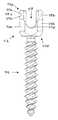
- FIG. 1Ais a side view of one embodiment of a bone screw assembly with a tapered receiver member
- FIG. 1Bis an enlarged view of the receiver member of FIG. 1A ;
- FIG. 1Cis a side view of the bone screw assembly of FIG. 1A , rotated 90 degrees;
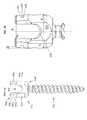
- FIG. 1Dis an exploded perspective view of the bone screw assembly of FIG. 1A , shown in a top loading configuration;
- FIG. 1Eis an exploded perspective view of an alternate embodiment of a bone screw assembly similar to FIG. 1A , but shown in a bottom loading configuration;
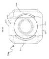
- FIG. 1Fis a top view of the bone screw assembly of FIG. 1A ;
- FIG. 1Gis a side view of an alternative slot configuration for the bone screw assembly of FIG. 1A ;
- FIG. 1His a side view of another alternative slot configuration for the bone screw assembly of FIG. 1A ;
- FIG. 1Iis a side view of another alternative slot configuration for the bone screw assembly of FIG. 1A ;
- FIG. 2Ais a side view of another embodiment of a bone screw assembly having four distinct slots
- FIG. 2Bis a side view of the bone screw assembly of FIG. 2A , rotated 90 degrees;
- FIG. 2Cis an isometric view of the bone screw assembly of FIG. 2A ;
- FIG. 2Dis a top view of the bone screw assembly of FIG. 2A ;
- FIG. 3Ais a side view of another embodiment of a bone screw assembly having a proximal lip
- FIG. 3Bis a side view of the bone screw assembly of FIG. 3A , rotated 90 degrees;
- FIG. 3Cis an isometric view of the bone screw assembly of FIG. 3A ;
- FIG. 4is a perspective view of a tool for mating with the bone screw assembly of FIG. 1A ;
- FIG. 5is a perspective view of a tool for mating with the bone screw assembly of FIG. 2A ;
- FIG. 6is a perspective view of a tool for mating with the bone screw assembly of FIG. 3A .
- Various exemplary spinal implant devices and methodsare provided.
- the devices and methodsprovide various robust attachment options for multiple instruments to be easily attached.
- spinal implantsare provided that allow for attachment to various instruments for various reasons, such as for rod approximation, head manipulation, or to locate a pathway to the receiver head through the skin.
- the implantscan allow for these attachments, while being robust enough to withstand axial loading as well as side loading during various surgical maneuvers and manipulations, such as compression/distraction and derotation.
- the spinal implants disclosed hereininclude a generally U-shaped rod-receiving head or receiver member having an open proximal end and a distal end coupled to a bone-engaging member, such as a bone screw, bone hook, etc.
- the receiver membercan have two side arms extending proximally from the distal end to the open proximal end, and defining a U-shaped channel therebetween to receive a spinal fixation element, such as a spinal rod.
- the side arms of the receivercan have various configurations and can include engagement features, such as slots or grooves, by which various tools can grasp the receiver member to manipulate the implant in various ways.
- Various configurations of the side armscan provide additional benefits, such as robustness or elimination of directionality when mating to various instruments.
- FIGS. 1A-1Dillustrate one embodiment of a bone screw assembly 100 .
- the bone screw assembly 100generally includes a receiver member 112 for receiving a spinal fixation element, such as a spinal rod, and a bone-engaging member 114 for engaging bone.
- the receiver member 112 and the bone-engaging member 114can be joined in a variety of ways.
- the bone-engaging member 114can be fixedly mated to or integrally formed with the receiver member 112 to form a monoaxial assembly.
- itcan be unidirectional, such that movement of the bone-engaging member is limited to a single direction, e.g., along a single plane, or it can be polyaxially coupled to the receiver member 112 to allow angular movement of the receiver member 112 relative to the bone-engaging member 114 .
- the receiver member 112can have a variety of configurations.
- the receiver member 112is in the form of a substantially U-shaped head with opposed first and second side arms 116 a , 116 b that extend proximally from a substantially closed distal base portion or distal end 112 d to an open proximal end 112 p .
- the side arms 116 a , 116 bare separated by opposed U-shaped slots that define a U-shaped channel 117 extending through the receiver head 112 for seating a spinal fixation element, such as a rod.
- the slots that define the channel 117can extend distally from the open proximal end 112 p and they can terminate at a location proximal to the closed distal end 112 d such that a spinal fixation element extending through the channel 117 is positioned a distance above the distal end 112 d of the receiver 112 .
- the receiver member 112can be configured to receive a variety of fixation elements. Suitable spinal fixation elements for use with the present invention include, by way of non-limiting examples, rods, tethers, cables, plates, etc.
- the spinal fixation elementscan have a variety of configurations, and, by way of non-limiting example, can be rigid, semi-rigid, bendable, flexible, etc.
- the substantially closed distal base portion 112 dcan have a variety of configurations, but in general the base portion 112 d can have a substantially cylindrical shape. However, a distal portion of the outer surface of the base portion 112 d can taper inward to have a truncated conical shape.
- the base portioncan also include opposed planar sidewalls 115 a , 115 b (shown in FIGS. 1A and 1F ) formed thereon.
- the planar sidewalls 115 a , 115 bcan be positioned distal of the U-shaped slots that define channel 117 , and the can extend partially around each slot.
- the planar sidewalls 115 a , 115 bcan also be positioned to extend between opposed lateral edges of the side arms 116 a , 116 b .
- the base portion 112 dcan have a concave cavity formed therein that seats a portion of the bone-engaging member 114 , and an opening extending therethrough that allows the bone-engaging member 114 to extend therethrough and into bone, as discussed in more detail below.
- the base portioncan be integrally formed and/or fixedly mated to the bone engaging member.
- the side arms of the receiver membercan also have various configurations.
- the side arms 116 a , 116 bcan extend substantially parallel to one another, and an outer surface of each side arm 116 a , 116 b can be semi-cylindrical.
- a proximal portion (only portion 116 ap is shown) of an outer surface of each of the first and second side arms 116 a , 116 bcan, however, taper inward toward one another.
- FIG. 1Bthe side arms 116 a , 116 b can extend substantially parallel to one another, and an outer surface of each side arm 116 a , 116 b can be semi-cylindrical.
- a proximal portion (only portion 116 ap is shown) of an outer surface of each of the first and second side arms 116 a , 116 bcan, however, taper inward toward one another.
- FIG. 1Bthe side arms 116 a , 116 b can extend substantially parallel to one another
- the first and second side arms 116 a , 116 btaper inward at a location proximal to a distal end 117 d of the U-shaped channel 117 and distal to the slots 118 a , 118 b , which will be discussed in more detail below.
- the tapercan also begin at a location proximal to opposed bores 120 a , 120 b formed in each side arm 116 a , 116 b , as will also be discussed in detail below.
- the angle of the tapercan vary. While the angle can vary, in an exemplary embodiment the angle ⁇ can be in a range of about 0 to 80 degrees, and more preferably about 0 to 45 degrees, and even more preferably about 0 to 10 degrees. In an exemplary embodiment, the outer surface of each of the first and second side arms tapers inward at an angle ⁇ of about 4 degrees, as shown in FIG. 1B .
- the side arms 116 a , 116 bcan also have a width extending between the opposed lateral edges that varies along the height of the side arm.
- each side arm 116 a , 116 bdecreases in width at a proximal portion thereof such that the side arms have a lateral width x 1 at the proximal portion (only portion 116 ap is shown) that is less than a lateral width x 2 of a distal portion (only portion 116 ad is shown) of each of the first and second side arms 116 a , 116 b .
- FIG. 1Ceach side arm 116 a , 116 b decreases in width at a proximal portion thereof such that the side arms have a lateral width x 1 at the proximal portion (only portion 116 ap is shown) that is less than a lateral width x 2 of a distal portion (only portion 116 ad is shown) of each of the first and second side arms 116 a
- the opposed lateral edges of the proximal portion 116 ap of each of the first and second side arms 116 a , 116 bextends parallel to the opposed lateral edges of the distal portion 116 ad of each of the first and second side arms 116 a , 116 b .
- Opposed lateral edges of both the proximal portion 116 ap and the distal portion 116 ad of the first and second side arms 116 a , 116 bcan also be substantially parallel to the longitudinal axis Z of the spinal implant 100 .
- the dimensions of the receiver member 112can vary dependent upon the intended use, but in an exemplary embodiment, as shown in FIG. 1B , the receiver member 112 can have a height H measured from a distal-most end of the substantially closed distal portion 112 d to a proximal-most end of the open proximal end 112 p that is in the range of about 9 mm to 150 mm and more preferably is about 14.5 mm.
- the substantially closed distal base portion 112 dcan have a maximum outer diameter D that is in the range of about 8 mm to 16 mm, and more preferably 13 mm.
- the open proximal end 112 p of the receiver member 112can have a minimum outer diameter D p that is in the range of about 6 mm to 16 mm, and more preferably about 13 mm.
- the receiver member 112can be formed from various biocompatible materials including, by way of non-limiting example, surgical grade titanium, surgical grade stainless steel, cobalt chromium, and nitinol.
- the receiver member 112can further include one or more engagement features, such as slots, formed on an external surface of the side arms for mating to various tools. As shown in the embodiment of FIGS. 1A-1D , an outer surface of each of the side arms 116 a , 116 b of the receiver member 112 includes first and second slots 118 a , 118 b formed therein for mating to a tool, such as a grasping tool, for example. Though this embodiment shows slots 118 a , 118 b located in the side arms 116 a , 116 b , the slots 118 a , 118 b can alternatively be located in the opposed substantially planar sides 115 a , 115 b .
- the slotscan have various configurations, but as shown in FIGS. 1A-1C , the slots 118 a , 118 b extend in a direction transverse to the longitudinal axis Z, and more preferably perpendicular to the longitudinal axis Z.
- the position of the slots 118 a , 118 bcan vary, but they are preferably positioned proximal to the distal end 117 d of the U-shaped channel 117 , and in an exemplary embodiment they are thus located on a proximal portion of the outer surface of the side arms 116 a , 116 b .
- the position of slots 118 a , 118 bcan depend on the material from which the receiver member is constructed.
- the slotscan be positioned closer to the proximal end 112 p of the receiver member 112 to allow the receiver member 112 to withstand the forces and pressures placed on the proximal end 112 p by an attached tool.
- the position of slots 118 a , 118 bis particularly advantageous in that it facilitates engagement of the bone screw assembly 100 by a rod approximator since the grasping tool, for example, does not need to grasp the bone screw assembly 100 underneath the receiver member 112 .
- the position of the slots 118 a , 118 balso avoids potential contact with adjacent bone structures.
- the slots 118 a , 118 bcan have various shapes and sizes as well, and various cutting techniques can be used to form the slots in the receiver member.
- the slots 118 a , 118 bare planar cut.
- the slots 118 a , 118 bare made with a cutting tool that forms elongated slots 118 a , 118 b having opposed upper and lower shoulders or superior and inferior surfaces 119 a , 119 b , connected by a planar back surface 119 c , as shown in FIGS. 1B and 1C .
- the upper and lower shoulders 119 a , 119 bcan extend parallel to one another along an entire length thereof.
- the planar back surface 119 ccan be parallel to the axis Z of the receiver member 112 .
- the upper and lower shoulders 119 a , 119can extend perpendicular to the axis Z of the receiver member 112 and to the planar back surface 119 c .
- the upper and/or lower shoulders 119 a , 119 bcan extend at an angle greater or less than 90 degrees relative to axis Z.
- FIG. 1Gillustrates an embodiment of opposed slots having upper and lower shoulders 119 a ′′, 119 b ′′ that are angled relative to one another.
- the angle ⁇ ′can vary, in an exemplary embodiment, the angle ⁇ ′ is in the range of about 0 to 120 degrees, and more preferably about 0 to 50 degrees, and most preferably about 20 degrees.
- the shoulders 119 a ′′′, 119 b ′′′can diverge away from one another at opposed terminal ends of the slots such that each slot has a dovetail shape and a distance between the superior and inferior surfaces is greater at the opposed terminal ends than at the mid-portion of the slot.
- FIG. 1Hthe shoulders 119 a ′′′, 119 b ′′′ can diverge away from one another at opposed terminal ends of the slots such that each slot has a dovetail shape and a distance between the superior and inferior surfaces is greater at the opposed terminal ends than at the mid-portion of the slot.
- both the upper and lower shoulderscan be substantially planar, but the upper shoulder can include opposed ends that are curved such that they extend proximally away from the lower shoulder.
- the curved shape of the upper shouldercan allow arms of a tool, such as a grasping member, to be inserted into the slots 118 a , 118 b at an angle.
- the slots 118 a , 118 b shown in the embodiment of FIGS. 1A-Dare planar cut, they can alternatively be radially cut such that the back surface is curved rather than planar.
- each slot 118 a , 118 bcan vary depending on the tool intended to be used with the receiver member.
- the length of each slot, as measured between opposed terminal ends of the slots 118 a , 118 bcan have a length that is at least about 50% of the width x 1 of the arms 116 a , 116 b .
- the depthcan also vary, but preferably the slots have a depth sufficient to allow a tool to grasp the receiver member 112 .
- the slots 118 a . 118 bcan have a length in the range of about 2 mm to 12 mm, and a depth in the range of about 0.5 mm to 3 mm.
- the bone-engaging memberwhich anchors the bone screw to bone and can be mated to the receiver member, can also have a variety of configurations.
- the bone-engaging member 114is in the form of a bone screw having a proximal head 114 p and a distal elongate shank portion 114 d with threads 124 formed on an outer surface thereof for engaging bone.
- the proximal head 114 pcan have a drive feature on a proximal portion thereof (not shown).
- the drive feature on the proximal head 114 pis identical in shape and size to the drive feature of a closure mechanism used to lock the spinal fixation rod in the receiver head, as will be discussed in more detail below.
- the distal tip of the shank 114 dcan also have a variety of configurations, and in one embodiment it can be self-tapping.
- the shank 114 dcan also be cannulated for advancing the shank over a guidewire, or it can be non-cannulated.
- the shank 114 dcan further include one or more fenestrations for allowing a material, such as a cement, to be injected into the shank.
- the size of the bone-engaging member 114 and the threads 124can vary depending on the intended use. In certain exemplary embodiments, the bone-engaging member 114 can have a length L 2 in the range of about 8 mm to 150 mm.
- the diameter D 2 of the proximal head 114 pcan vary, and can be in the range of about 4 mm to 10 mm.
- a minor diameter d m of the shank 114 dcan remain constant along the entire length of the shank 114 d , or the minor diameter d m can decrease in a proximal-to-distal direction, as shown in FIGS. 1A and 1B .
- a major diameter d M of the shank 114i.e., the diameter of the threads 124 , can also vary, and can remain constant or can likewise taper.
- the major diameter d Mcan be in the range of about 3 mm to 12 mm, and the minor diameter d m can be in the range of about 2.0 mm to 10 mm.
- a thread pitch, or number of threads per unit length,can also vary, and in one embodiment the thread pitch can be in the range of about 1 mm to 4 mm.
- the bone-engaging member 114can also be formed from various biocompatible materials including, by way of non-limiting example, surgical grade titanium, surgical grade stainless steel, cobalt chromium, and nitinol. It can be formed from either the same or different materials as the receiver member 112 .
- a person skilled in the artwill appreciate that, while a bone screw is shown, various other bone implants can be used, such as spinal hooks, cross connectors, plates, staples or fixation element connectors.
- the bone-engaging member 114can be coupled to the receiver in various ways. It can be fixedly mated to and/or integrally formed with the receiver member 112 such that the assembly is monoaxial, or alternatively, the bone-engaging member 114 can be unidirectional or polyaxially coupled to the receiver member 112 to allow angular movement of the receiver member relative to the shank. A variety of techniques can be used to allow angular movement of the receiver member 112 with respect to the bone-engaging member 114 .
- the proximal head 114 pcan be hemispherical and can be seated in a concave cavity formed in the base portion of the receiver member 112 , with the bone-engaging member 114 extending through the opening formed in the substantially closed distal portion 112 d of the receiver member 112 such that in can be angularly oriented relative to the receiver member 112 .
- the proximal head 114 pcan prevent the bone-engaging member 114 from extending completely through the opening or an additional component may be added to retain the bone engaging member within the receiver. This configuration is illustrated in FIG. 1D .
- the bone screw assembly 100can be assembly using a top loading approach, in which the bone-engaging member 114 is inserted into the top of the receiver member 112 and advanced through the opening in the bottom of the receiver member 112 .
- the bone screw assemblycan be bottom loading, in which the bone-engaging member is inserted into the bottom of the receiver.
- FIG. 1ESuch a configuration is illustrated, by way of non-limiting example, in FIG. 1E .
- the bone-engaging member 114 ′has a post 115 ′ at the proximal end, rather than a head. This allows the post 115 ′ to be inserted into the bottom of the receiver 112 ′, and engaged by a separate head 114 p ′.
- the bone-engaging membercan be top loading or bottom loading.
- the implantcan also have a compression cap that, when compressed by a spinal fixation element, can lock the bone-engaging member 114 into a fixed position such that it is no longer movable.
- the bone screw assembly 100can include a compression cap 130 that is received in the receiver member 112 and configured to be positioned between the proximal head 114 p of the bone-engaging member 114 , and a spinal fixation element, such as a rod, disposed within the U-shaped channel 117 of the receiver member 112 .
- the compression cap 130can have a hole formed therethrough such that the drive feature on the proximal head 114 p of the bone-engaging member is accessible when the compression cap 130 is disposed within the U-shaped channel 117 over the proximal head 114 p .
- the compression cap 130can allow free polyaxial movement of the receiver member 112 relative to the shank 114 when a spinal fixation element is disposed within the receiver member 112 , and the compression cap 130 can be configured to lock the shank 114 in a fixed orientation relative to the receiver 112 when a closure mechanism 180 is applied to the receiver member 112 to lock the spinal fixation element relative to the receiver 112 .
- the compression capcan be configured to lock the bone-engaging member in a fixed position relative to the receiver member without locking the spinal fixation element relative to the receiver.
- a separate closure mechanismcan be used to lock the spinal fixation element to the receiver member.
- the receiver member 112can also include features to retain and/or lock the compression cap 130 therein.
- an outer surface of each side arm 116 a , 116 bcan include first and second bores 120 a , 120 b formed therein, and an inner sidewall of each arm 116 a , 116 b can be deformable such that, when a pin or other member is inserted into each bore 120 a , 120 b , the deformable portion swages inward to engage the compression cap 130 and prevent proximal movement of the compression cap 130 disposed within the receiver member 112 .
- the bores 120 a , 120 bcan be positioned at any location on the receiver member 112 .
- the bores 120 a , 120 bare positioned at a mid-portion of each side arm 116 a , 116 b , and at a location distal to the first and second slots 118 a , 118 b .
- the compression cap 130can be formed from various biocompatible materials including, by way of non-limiting example, surgical grade titanium, surgical grade stainless steel, cobalt chromium, nitinol, PEEK and plastics. It can be formed from either the same or different materials as the receiver member 112 and the bone-engaging member 114 .
- closure mechanismcan engage with the receiver member 112 in various ways.
- the closure mechanismis a set screw 180 that is received in the open proximal end 112 p of the receiver member 112 , between the side arms 116 a , 116 b .
- the receiver member 112can include various features for mating with a closure mechanism, for example, in an exemplary embodiment, threads 122 on the proximal portion of the inner surface of the side arms 116 a , 116 b mate with the corresponding threads on the set screw 180 to lock a spinal fixation rod therein, as shown in FIG. 1D .
- the set screw 180can also include a drive feature 182 therethrough or located on a proximal portion thereof.
- the drive feature 182can match the drive feature of proximal head 114 p such that the same tool can be used on both drive features, or the drive feature can be different than that of the proximal head 114 p .
- alternative closure mechanismscan be used, e.g., external locking nut, or a combination internal and external, etc.
- the closure mechanismcan be formed from various biocompatible materials including, by way of non-limiting example, surgical grade titanium, surgical grade stainless steel, cobalt chromium, and nitinol. It can be formed from either the same or different materials as the receiver member 112 , the bone-engaging member 114 , and the compression cap 130 .
- FIGS. 2A-2Dillustrate another embodiment of a bone screw assembly 200 , which is similar to bone screw assembly 100 , having a substantially U-shaped receiver member 212 that has an open proximal end 212 p and a substantially closed distal end 212 d .
- Receiver member 212is similar to receiver member 112 and can thus include any of the features discussed above with respect to receiver 112 .
- receiver member 212has opposed first and second side arms 216 a , 216 b that extend proximally from the substantially closed distal end 212 d to the open proximal end 212 p of the receiver member 212 .
- first and second side arms 216 a , 216 bhave substantially planar outer surfaces ( 223 a shown in FIG. 2B ; 223 b shown in FIG. 2D ) and substantially cylindrical lateral edges ( 221 a , 221 b are shown in FIG. 2B ; 221 d is shown in FIG. 2C ; 221 c is not shown).
- receiver member 212has a generally square shape with first, second, third, and fourth planar sides.
- the receiver member 212has first and second opposed substantially planar sides 215 a , 215 b extending proximally from the substantially closed distal end 212 d and extending between the side arms 216 a , 216 b , with the side arms 216 a , 216 b forming third and fourth substantially planar sides.
- the planar outer surfaces 223 a , 223 b of the side arms 216 a , 216 bcan be parallel to one another and can each extend parallel to the longitudinal axis Z.
- the opposed substantially planar sides 215 a , 215 b extending between the side arms 216 a , 216 b , and having the U-shaped slots formed therein,can also each extend parallel to the longitudinal axis Z, and they can extend perpendicular to the planar outer surfaces 223 a , 223 b of side arms 216 a , 216 b .
- the bone screw assembly 200can have a substantially square cross-sectional shape taken in a plane extending perpendicular to the longitudinal axis Z.
- a proximal portion of the outer surface of each of the first and second side arms 216 a , 216 bcan be substantially the same as a width of a distal portion of the outer surface of each of the first and second side arms 216 a , 216 b , or in alternative embodiments the arms can taper at any location along the height thereof.
- the receiver member 212can have a height H 2 , measured from a distal end of the substantially closed distal portion 212 d to a proximal-most point of the open proximal end 212 p , as shown in FIG. 2B , in the range of about 9 mm to 150 mm, and more preferably 14.5 mm.
- the receiver member 212can have a maximum diameter D 2 in the range of about 8 mm to 16 mm, and more preferably 13 mm.
- the receiver member 212can also include one or more engagement features for mating to various tools.
- the receiver member 212has first, second, third, and fourth slots separate and distinct slots 218 a , 218 b , 218 c , 218 d formed therein.
- the slots 218 a , 218 b , 218 c , 218 dcan have various configurations and can be located at various locations on the receiver member 212 .
- the slots 218 a , 218 b , 218 c , 218 dcan all extend in the same plane and can be spaced equidistance from one another radially around the receiver member 212 .
- first side arm 216 acan contain the first and second slots 218 a , 218 b with a gap between them on the planar outer surface 223 a
- second side arm 216 bcan contain the third and fourth slots 218 c , 218 d with a gap between them on the planar outer surface 223 b .
- Each slot 218 a , 218 b , 218 c , 218 dcan be disposed partially across one of the planar outer surfaces 223 a , 223 b of one of the side arms 216 a , 216 b and one of the lateral edges 221 a , 221 b , 221 c , 221 d on the corresponding side arm 216 a , 216 b .
- the four symmetric slots 218 a , 218 b , 218 c , 218 d of receiver member 212can allow certain instruments to engage the receiver member 212 in four distinct orientations, eliminating directionality of instruments.
- the locationcan vary, but in the illustrated embodiment the slots 218 a , 218 b , 218 c , 218 d can be located proximal to the distal ends 217 ad , 217 bd of the U-shaped cut-outs 217 a , 217 b .
- the slots 218 a , 218 b , 218 c , 218 dare located as close to the top of the bone screw assembly 200 as possible, but the location can be dependent on factors such as the material from which the receiver member 212 is constructed, as explained above with respect to receiver 112 .
- a distance q between the upper shoulder 219 a of each slot and the proximal-most end surface 212 p of the receiveris in the range of about 1 mm to 10 mm.
- the slots 218 a , 218 b , 218 c , 218 dcan be formed in the receiver member using various techniques.
- the slotsare radially cut around the receiver member 212 , for example, with a cutting tool that has a diameter slightly less than an outer diameter of the receiver member 212 .
- the maximum outer diameter of the receiver memberis in the range of about 8 mm to 16 mm, and the slots have a diameter that is in the range of about 7 mm to 15 mm.
- the slots 218 a , 218 b , 218 c , 218 dare only formed along the corners of the square cross-section, i.e., the lateral edges of the side arms 216 a , 216 b . This results in a gap between slots on a middle portion of each of the planar outer surfaces 223 a , 223 b .
- the slots 218 a , 218 b , 218 c , 218 dcan each have upper and lower shoulders 219 a , 219 b , which can each be substantially planar, and a curved back surface 219 c .
- the upper and lower shoulders 219 a , 219 bcan be substantially parallel to one another and substantially perpendicular to the longitudinal axis Z.
- one or both shoulders 219 a , 219 bcan diverge or be curved at a terminal end portion thereof, and/or the shoulders 219 a , 219 b can extend at an angle relative to one another, e.g., in the range of about 0 degrees to 120 degrees, and more preferably about 0 to 50 degrees, and most preferably about 20 degrees, as previously discussed above with respect to slots 118 a , 118 b.
- FIGS. 3A-3Cillustrate another embodiment of a bone screw assembly 300 that is also similar to implant 100 and that has a substantially U-shaped receiver member 312 with an open proximal end 312 p and a substantially closed distal end 312 d .
- the bone screw assembly 300can thus include any of the features previously discussed above with respect to implant 100 and/or bone screw assembly 200 .
- the receiver member 312has opposed first and second side arms 316 a , 316 b that extend proximally from the substantially closed distal end 312 d to the open proximal end 312 p of the receiver member 312 .
- the receiver member 312can also have opposed substantially planar sides 315 a , 315 b extending proximally from the substantially closed distal end 312 d and between side arms 316 a , 316 b .
- a top view of the open proximal end 312 p of the side arms 316 a , 316 b of the receiver member 312is identical to the top view of the previous embodiment shown in FIG. 2D .
- each planar outer surface on the first and second opposed side arms 316 a , 316 btapers.
- each arm 316 a , 316 bcan have a distal planar outer surface 316 ad , 316 bd and a proximal tapering outer surface 316 ap , 316 bp that extends proximally from the distal planar outer surface 316 ad , 316 bd .
- the distal planar outer surfaces 316 ad , 316 bdcan extend parallel to one another and parallel to a longitudinal axis Z of the bone screw assembly 300 , and they can be perpendicular to the open proximal end 312 p of receiver member 312 .
- inner surfaces of the side arms 316 a , 316 bremain equidistant to each other along the entire length thereof.
- the tapering outer surface 316 ap , 316 bpcan begin at any location, but preferably the taper originates at a location proximal to the bore holes 320 a , 320 b formed in the side arms 316 a , 316 b .
- the tapering outer surfaces 316 a , 316 pcan taper inward proximally at various angles.
- each tapering outer surface 316 ap , 316 bptapers inward at an angle ⁇ 2 as measured from a plane of the distal planar outer surface 316 ad , 316 bd .
- the taper angle ⁇ 2is in the range of about 0 to 80 degrees, and more preferably about 0 to 45 degrees, and even more preferably about 10 degrees. In an exemplary embodiment, the angle ⁇ 2 is about 4 degrees.
- each side arm 316 a , 316 bp of each side arm 316 a , 316 bcan terminate at a location just distal to the proximal-most end of the receiver member, such that each side arms 316 a , 316 b includes a proximal lip 318 a , 318 b formed thereon extending between opposed lateral edges of the side arm 316 a , 316 b at proximal end 312 p .
- Each lipcan have a width that is substantially the same as a width of the side arms 316 a , 316 b .
- the proximal lip 318 a , 318 bcan have an inferior surface 319 b that abuts the tapering outer surface 316 ap , 316 bp .
- the proximal lipcan also have a superior surface 319 a that is located at the proximal end 312 p of the receiver member 312 .
- the inferior surface 319 bcan be located a distance q 2 from the superior surface 319 a , and thus from the proximal end 312 p .
- the distance q 2 between the inferior surface 319 b of the proximal lip 318 a , 318 bis in the range of about 1 mm to 4 mm, making the proximal lip 318 a , 318 b of this embodiment relatively narrow.
- the proximal lip 318 a , 318 bcan provide a more robust attachment than other grasping elements, such as slots, on the receiver member 312 for instruments to grasp due to the length of the proximal lip 318 a , 318 b .
- proximal lip 318 a , 318 bcan provide more material, i.e., an entire width of a side arm 316 a , 316 b for attachment and can thereby accommodate a thinner profile than, for example, the slots 218 a , 218 b , 218 c , 218 d in the previous embodiment, which each only provide a corner of the receiver member 212 for an instrument to grasp.
- the greater surface area for grasping provided by the proximal lip 318 a , 318 ballows for a narrower distance q 2 between the grasping element and the proximal end 312 p than in other embodiments which have smaller surface areas for grasping, e.g., the distance q in receiver member 212 .
- the superior and inferior surfaces 319 a , 319 b of the proximal lip 318 , 318 bcan be parallel to each other and can be perpendicular to the longitudinal axis Z of the receiver member.
- the inferior surface 319 bcan extend at an angle ⁇ 2 relative to a superior surface 319 a of the proximal lip.
- angle ⁇ 2can vary, in one embodiment the angle ⁇ 2 can be in the range of about 0 to 89 degrees, and more preferably about 0 to 30 degrees, and most preferably the angle is about 10 degrees.
- the angle ⁇ 2can result from one or both surfaces 319 a , 319 b extending at an angle other than 90 degrees relative to the axis z.
- the receiver member 312can have a height H 3 , measured from a distal end of the substantially closed distal portion 312 d to a proximal-most point of the open proximal end 312 p , as shown in FIG. 3B , in the range of about 9 mm to 150 mm but is preferably about 14.5 mm.
- the substantially closed distal base portion 312 dcan have a diameter D 3 ranging from about 8 mm to 16 mm, but is preferably around 13 mm.
- a width x 3 of the tapering outer surface 316 ap , 316 bp of each of the first and second side arms 316 a , 316 bcan be substantially the same as the width D 3 of the distal planar outer surfaces 316 ad , 316 bd.
- the illustrated spinal implantscan be used to stabilize a variety of bone structures, including by way of non limiting example, vertebral bodies, lateral masses, lamina and transverse process.
- the first stepis positioning and driving the anchor, e.g., the bone screw, to the desired depth in the vertebra.
- the anchore.g., the bone screw
- a guidewirecan be used to position the bone screw.
- the cannulated bone screwcan be advanced over the guidewire, which allows placement of the bone screw at a desired depth in bone.
- a pre-drilled holecan optionally be formed prior to advancing the bone screw over the guidewire.
- the bone screwcould have one or more fenestrations formed therein for allowing a material, such as a cement, to be injected into the bone screw to enhance fixation.
- a materialsuch as a cement
- the screwis preferably inserted into a hole that is pre-drilled in bone using a drilling tool. Both cannulated and non-cannulated screws can be self-tapping to allow the screw to drive through bone.
- various techniques known in the artcan be used to implant the bone screw in bone.
- a spinal fixation elementcan be inserted into the receiver member of each screw. It can be difficult to position the spinal fixation element within each receiver member because of the alignment of the bone screws and the dimensions of the surgical site.
- a rod approximator or reduction devicecan be used to place the fixation element in the receiver members.
- the arms of the rod approximator devicecan include a grasping member with arms that contain grasping elements that fit into the corresponding recesses on the receiver member of the bone screw, stabilizing the rod approximator relative to the bone screw.
- the rod approximatorcan also include first and second handle members that can be grasped and squeezed together to cause the rod pusher member to move to a second, distal position, thereby causing the rod engaging member to grasp and push the fixation rod into the receiver member of the bone screw.
- a closure mechanismcan be applied to the receiver member of the bone screw to secure the rod.
- FIGS. 4-6illustrates a distal portion of a tool for grasping the receiver member of a spinal anchor, such as the bone screw assemblies shown in FIGS. 1A , 2 A, and 3 A.
- a spinal anchorsuch as the bone screw assemblies shown in FIGS. 1A , 2 A, and 3 A.
- FIGS. 4-6are intended to represent any type of tool used to grasp an implant.
- Such toolscan generally include features as shown that are configured to fit into and engage corresponding mating features shown in the spinal implants.
- FIG. 4illustrates a rod approximator device 190 that can be used to grasp and stabilize receiver member 112 , while pushing the spinal fixation element into the U-shaped channel 117 formed in the receiver member 112 of the spinal implant 100 .
- the device 190can also be used to hold the bone screw assembly 100 , while the closure mechanism 180 is threaded into the receiver member 112 of the spinal implant 100 to secure the stabilizing rod in the U-shaped channel 117 , and thereby lock the receiver member 112 in a fixed position relative to the bone screw.
- the rod approximator device 190has opposed arms 194 a , 194 b located on a distal end of a grasping member 192 that are configured to surround and grasp the proximal portion 116 ap , 116 bp of the receiver member 112 .
- the arms 194 a , 194 bcan have grasping elements 196 a , 196 b formed on an inner surface thereof, such that grasping elements 196 a , 196 b can mate with corresponding slots 118 a , 118 b of the receiver member 112 of the implant 100 .
- the grasping elements 196 a , 196 bare in the form of protrusions that have en elongate length with a shape and size configured to match the shape and size of the cavity defined by the slots 118 a , 118 b .
- the inner surface of arms 194 a , 194 bcan taper inward in a distal-to-proximal direction such that it corresponds with the taper of the proximal portion 116 ap , 116 bp of side arms 116 .
- FIG. 5illustrates another embodiment of a rod approximator device 290 for use with bone screw assembly 200 .
- the device 290has opposed arms 294 a , 294 b , located on a distal end of a grasping member 292 , that are configured to surround and grasp the proximal portion of the side arms 216 a , 216 b of the receiver member 212 .
- the arms 294 a , 294 bcan have grasping elements 296 a , 296 b , 296 c , 296 d formed on an inner surface thereof, such that grasping elements 296 a , 296 b , 296 c , 296 d can mate with corresponding slots 218 a , 218 b , 218 c , 218 d of the receiver member 212 of the bone screw assembly 200 .
- the grasping elements 296 a , 296 b , 296 c , 296 dare in the form of four separate and distinct protrusions that are positioned, shaped, and sized to correspond to the slots 218 a , 218 b , 218 c , 218 d of the receiver member 212 .
- the inner surface of arms 194 a , 194 bcan mirror the planar and semi-cylindrical outer surfaces of the receiver member 212 .
- the four symmetric slots 218 a , 218 b , 218 c , 218 d of receiver member 212can allow certain instruments, such as the grasping member 292 , to engage the receiver member 212 in four distinct orientations, eliminating directionality and allowing a user to choose the direction of the connection. Some instruments can only engage the receiver member 212 in four distinct orientations when there is no rod located in the U-shaped cut-outs 217 a , 217 b , and some instruments have rod slots, in which it would be desirable to engage the receiver member 212 in only two of the four distinct orientations to align the rod slots with the U-shaped cut-outs 217 a , 217 b .
- a spinal fixation rodcan be pushed into the U-shaped cut-outs 217 a , 217 b formed in the receiver member 212 of the bone screw assembly 200 , and a closure mechanism 180 can be threaded into the receiver member 212 of the bone screw assembly 200 , while device 290 is stabilizing the bone screw assembly 200 with respect to the spinal fixation element.
- FIG. 6illustrates one embodiment of a rod approximator device 390 for use with bone screw assembly 300 .
- the arms 394 a , 394 b located on the distal end of a grasping member 392can surround and grasp the tapering outer surface 316 ap , 316 bp of the receiver member 312 .
- the arms 394 a , 394 bhave grasping elements 396 a , 396 b formed on an inner surface thereof, such that grasping elements 396 a , 396 b can mate with the corresponding slots under the inferior surface 319 b of the proximal lip 318 a , 318 b of the receiver member 312 of the bone screw assembly 300 .
- the grasping elements 396 a , 396 bcan be in the form of elongate rectangular protrusions that are positioned, shaped, and sized to correspond to the slots.
- the inner surface of arms 394 a , 394 bcan taper inward in a distal-to-proximal direction such that it corresponds with the taper of the tapering outer surface 316 ap , 316 bp of the side arms 316 a , 316 b .
- the bone screw assembly 300can be stabilized while the spinal fixation element is pushed into the U-shaped rod-receiving recesses 317 a , 317 b formed in the receiver member 312 of the bone screw assembly 300 and while the closure mechanism 180 can be threaded into the receiver member 312 of the bone screw assembly 300 to secure the stabilizing rod in the U-shaped rod-receiving recesses 317 a , 317 b.
- bone anchorscan be used in a pedicle, a person skilled in the art will appreciate that the bone anchors disclosed herein can be used in all types of human skeletal structures. This includes, by way of non-limiting examples, vertebra, femur, tibia, hip, and skull.
Landscapes
- Health & Medical Sciences (AREA)
- Orthopedic Medicine & Surgery (AREA)
- Neurology (AREA)
- Life Sciences & Earth Sciences (AREA)
- Surgery (AREA)
- Heart & Thoracic Surgery (AREA)
- Engineering & Computer Science (AREA)
- Biomedical Technology (AREA)
- Nuclear Medicine, Radiotherapy & Molecular Imaging (AREA)
- Medical Informatics (AREA)
- Molecular Biology (AREA)
- Animal Behavior & Ethology (AREA)
- General Health & Medical Sciences (AREA)
- Public Health (AREA)
- Veterinary Medicine (AREA)
- Surgical Instruments (AREA)
- Prostheses (AREA)
Abstract
Description
Claims (18)
Priority Applications (3)
| Application Number | Priority Date | Filing Date | Title |
|---|---|---|---|
| US13/223,831US9060818B2 (en) | 2011-09-01 | 2011-09-01 | Bone implants |
| PCT/US2012/052448WO2013032982A1 (en) | 2011-09-01 | 2012-08-27 | Bone implants |
| US14/716,188US9814506B2 (en) | 2011-09-01 | 2015-05-19 | Bone implants |
Applications Claiming Priority (1)
| Application Number | Priority Date | Filing Date | Title |
|---|---|---|---|
| US13/223,831US9060818B2 (en) | 2011-09-01 | 2011-09-01 | Bone implants |
Related Child Applications (1)
| Application Number | Title | Priority Date | Filing Date |
|---|---|---|---|
| US14/716,188ContinuationUS9814506B2 (en) | 2011-09-01 | 2015-05-19 | Bone implants |
Publications (2)
| Publication Number | Publication Date |
|---|---|
| US20130060294A1 US20130060294A1 (en) | 2013-03-07 |
| US9060818B2true US9060818B2 (en) | 2015-06-23 |
Family
ID=47753725
Family Applications (2)
| Application Number | Title | Priority Date | Filing Date |
|---|---|---|---|
| US13/223,831Active2032-06-05US9060818B2 (en) | 2011-09-01 | 2011-09-01 | Bone implants |
| US14/716,188Active2031-11-04US9814506B2 (en) | 2011-09-01 | 2015-05-19 | Bone implants |
Family Applications After (1)
| Application Number | Title | Priority Date | Filing Date |
|---|---|---|---|
| US14/716,188Active2031-11-04US9814506B2 (en) | 2011-09-01 | 2015-05-19 | Bone implants |
Country Status (2)
| Country | Link |
|---|---|
| US (2) | US9060818B2 (en) |
| WO (1) | WO2013032982A1 (en) |
Cited By (3)
| Publication number | Priority date | Publication date | Assignee | Title |
|---|---|---|---|---|
| US9814506B2 (en) | 2011-09-01 | 2017-11-14 | DePuy Synthes Products, Inc. | Bone implants |
| US20180132911A1 (en)* | 2015-05-12 | 2018-05-17 | Shandong Weigao Orthopedic Device Company Ltd | Grasping end of frog-style forceps |
| USD956233S1 (en)* | 2020-04-24 | 2022-06-28 | Solco Biomedical Co., Ltd. | Cervical screw |
Families Citing this family (19)
| Publication number | Priority date | Publication date | Assignee | Title |
|---|---|---|---|---|
| US9259247B2 (en) | 2013-03-14 | 2016-02-16 | Medos International Sarl | Locking compression members for use with bone anchor assemblies and methods |
| US10368923B2 (en)* | 2014-10-28 | 2019-08-06 | Neurostructures, Inc. | Bone fixation system |
| US9956003B2 (en)* | 2015-09-18 | 2018-05-01 | Warsaw Orthopedic, Inc | Spinal implant system and methods of use |
| US10064662B2 (en)* | 2016-08-12 | 2018-09-04 | Amendia, Inc. | Minimally invasive screw extension assembly |
| WO2018084325A1 (en)* | 2016-11-01 | 2018-05-11 | 김민나 | Vertebral implant screw assembly |
| US10736665B2 (en)* | 2017-02-24 | 2020-08-11 | Warsaw Orthopedic, Inc. | Spinal implant system and method |
| US10512547B2 (en) | 2017-05-04 | 2019-12-24 | Neurostructures, Inc. | Interbody spacer |
| US10980641B2 (en) | 2017-05-04 | 2021-04-20 | Neurostructures, Inc. | Interbody spacer |
| US11076892B2 (en) | 2018-08-03 | 2021-08-03 | Neurostructures, Inc. | Anterior cervical plate |
| US11071629B2 (en) | 2018-10-13 | 2021-07-27 | Neurostructures Inc. | Interbody spacer |
| US11849981B2 (en) | 2019-01-30 | 2023-12-26 | Medos International Sarl | Systems and methods for en bloc derotation of a spinal column |
| US11382761B2 (en) | 2020-04-11 | 2022-07-12 | Neurostructures, Inc. | Expandable interbody spacer |
| US11304817B2 (en) | 2020-06-05 | 2022-04-19 | Neurostructures, Inc. | Expandable interbody spacer |
| US11717419B2 (en) | 2020-12-10 | 2023-08-08 | Neurostructures, Inc. | Expandable interbody spacer |
| US11627992B2 (en) | 2020-12-21 | 2023-04-18 | Warsaw Orthopedic, Inc. | Locking-cap module and connector |
| US11627995B2 (en)* | 2020-12-21 | 2023-04-18 | Warsaw Orthopedic, Inc. | Locking-cap module and connector |
| WO2022184797A1 (en) | 2021-03-05 | 2022-09-09 | Medos International Sarl | Selectively locking polyaxial screw |
| US12364515B2 (en)* | 2021-03-05 | 2025-07-22 | Medos International Sàrl | Multi-feature polyaxial screw |
| US12274479B2 (en) | 2022-07-08 | 2025-04-15 | Warsaw Orthopedic, Inc. | Cement delivery guides and corresponding fenestrated screws |
Citations (94)
| Publication number | Priority date | Publication date | Assignee | Title |
|---|---|---|---|---|
| US5176679A (en) | 1991-09-23 | 1993-01-05 | Lin Chih I | Vertebral locking and retrieving system |
| US5261913A (en) | 1989-07-26 | 1993-11-16 | J.B.S. Limited Company | Device for straightening, securing, compressing and elongating the spinal column |
| US5360431A (en) | 1990-04-26 | 1994-11-01 | Cross Medical Products | Transpedicular screw system and method of use |
| US5397363A (en) | 1992-08-11 | 1995-03-14 | Gelbard; Steven D. | Spinal stabilization implant system |
| US5466237A (en) | 1993-11-19 | 1995-11-14 | Cross Medical Products, Inc. | Variable locking stabilizer anchor seat and screw |
| WO1996002198A1 (en) | 1994-07-18 | 1996-02-01 | Lutz Biedermann | Anchorage component and adjusting device therefor |
| US5545165A (en) | 1992-10-09 | 1996-08-13 | Biedermann Motech Gmbh | Anchoring member |
| US5554157A (en) | 1995-07-13 | 1996-09-10 | Fastenetix, L.L.C. | Rod securing polyaxial locking screw and coupling element assembly |
| US5586984A (en) | 1995-07-13 | 1996-12-24 | Fastenetix, L.L.C. | Polyaxial locking screw and coupling element assembly for use with rod fixation apparatus |
| US5643264A (en) | 1995-09-13 | 1997-07-01 | Danek Medical, Inc. | Iliac screw |
| US5643260A (en) | 1995-02-14 | 1997-07-01 | Smith & Nephew, Inc. | Orthopedic fixation system |
| US5647873A (en) | 1995-04-13 | 1997-07-15 | Fastenetix, L.L.C. | Bicentric polyaxial locking screw and coupling element |
| US5669911A (en) | 1995-04-13 | 1997-09-23 | Fastenetix, L.L.C. | Polyaxial pedicle screw |
| US5672176A (en) | 1995-03-15 | 1997-09-30 | Biedermann; Lutz | Anchoring member |
| US5676703A (en) | 1994-05-11 | 1997-10-14 | Gelbard; Steven D. | Spinal stabilization implant system |
| WO1997037604A1 (en) | 1996-04-09 | 1997-10-16 | Waldemar Link (Gmbh & Co.) | Spinal fixing device |
| US5728098A (en) | 1996-11-07 | 1998-03-17 | Sdgi Holdings, Inc. | Multi-angle bone screw assembly using shape-memory technology |
| US5738685A (en) | 1993-05-18 | 1998-04-14 | Schafer Micomed Gmbh | Osteosynthesis device |
| US5797911A (en) | 1996-09-24 | 1998-08-25 | Sdgi Holdings, Inc. | Multi-axial bone screw assembly |
| US5863293A (en) | 1996-10-18 | 1999-01-26 | Spinal Innovations | Spinal implant fixation assembly |
| US5879350A (en) | 1996-09-24 | 1999-03-09 | Sdgi Holdings, Inc. | Multi-axial bone screw assembly |
| US5885286A (en) | 1996-09-24 | 1999-03-23 | Sdgi Holdings, Inc. | Multi-axial bone screw assembly |
| US5899904A (en) | 1998-10-19 | 1999-05-04 | Third Milennium Engineering, Llc | Compression locking vertebral body screw, staple, and rod assembly |
| US5899905A (en) | 1998-10-19 | 1999-05-04 | Third Millennium Engineering Llc | Expansion locking vertebral body screw, staple, and rod assembly |
| US5925047A (en) | 1998-10-19 | 1999-07-20 | Third Millennium Engineering, Llc | Coupled rod, anterior vertebral body screw, and staple assembly |
| US6019762A (en) | 1998-04-30 | 2000-02-01 | Orthodyne, Inc. | Adjustable length orthopedic fixation device |
| WO2001006940A1 (en) | 1999-07-22 | 2001-02-01 | Stryker Spine | Multiaxial connection for osteosynthesis |
| US6302888B1 (en) | 1999-03-19 | 2001-10-16 | Interpore Cross International | Locking dovetail and self-limiting set screw assembly for a spinal stabilization member |
| US20020026193A1 (en) | 1999-09-01 | 2002-02-28 | B. Thomas Barker | Multi-axial bone screw assembly |
| WO2002054966A2 (en) | 2001-01-12 | 2002-07-18 | Depuy Acromed, Inc. | Polyaxial screw with improved locking |
| US20020116001A1 (en)* | 2001-02-17 | 2002-08-22 | Bernd Schafer | Bone screw |
| US6443953B1 (en) | 2000-02-08 | 2002-09-03 | Cross Medical Products, Inc. | Self-aligning cap nut for use with a spinal rod anchor |
| US6478797B1 (en) | 2001-05-16 | 2002-11-12 | Kamaljit S. Paul | Spinal fixation device |
| US6485491B1 (en)* | 2000-09-15 | 2002-11-26 | Sdgi Holdings, Inc. | Posterior fixation system |
| US6520963B1 (en) | 2001-08-13 | 2003-02-18 | Mckinley Lawrence M. | Vertebral alignment and fixation assembly |
| WO2003028566A1 (en) | 2001-10-04 | 2003-04-10 | Stryker Spine | Spinal osteosynthesis assembly comprising the head of an anchoring member and a tool for fixing said head |
| US6554834B1 (en) | 1999-10-07 | 2003-04-29 | Stryker Spine | Slotted head pedicle screw assembly |
| US6695843B2 (en) | 2000-12-22 | 2004-02-24 | Biedermann Motech Gmbh | Fixing element |
| US20040167525A1 (en) | 2002-09-06 | 2004-08-26 | Jackson Roger P. | Anti-splay medical implant closure with multi-stepped removal counterbore |
| US6786903B2 (en) | 2002-01-24 | 2004-09-07 | A-Spine Holding Group Corp. | Rotary device for fixing spinal column under treatment |
| US6843791B2 (en) | 2003-01-10 | 2005-01-18 | Depuy Acromed, Inc. | Locking cap assembly for spinal fixation instrumentation |
| US20050049588A1 (en) | 2003-08-28 | 2005-03-03 | Jackson Roger P. | Polyaxial bone screw with split retainer ring |
| US20050131410A1 (en) | 2003-12-11 | 2005-06-16 | A-Spine Holding Group Corp. | Rotary device for retrieving spinal column under treatment |
| US6918911B2 (en) | 2002-03-27 | 2005-07-19 | Biedermann Motech Gmbh | Bone anchoring device for stabilizing bone segments and seat part of a bone anchoring device |
| US20050177154A1 (en)* | 2000-09-22 | 2005-08-11 | Missoum Moumene | Locking cap assembly for spinal fixation instrumentation |
| WO2005074823A1 (en) | 2004-02-09 | 2005-08-18 | Medixalign Co., Ltd. | Bone fixation apparatus |
| US6974460B2 (en) | 2001-09-14 | 2005-12-13 | Stryker Spine | Biased angulation bone fixation assembly |
| US20050277927A1 (en)* | 2004-06-14 | 2005-12-15 | Guenther Kevin V | Fastening system for spinal stabilization system |
| US6997927B2 (en) | 2000-12-08 | 2006-02-14 | Jackson Roger P | closure for rod receiving orthopedic implant having a pair of spaced apertures for removal |
| US20060036242A1 (en) | 2004-08-10 | 2006-02-16 | Nilsson C M | Screw and rod fixation system |
| US20060064089A1 (en) | 2004-09-07 | 2006-03-23 | Jackson Roger P | Bone screw closure having domed rod engaging surface |
| US20060100622A1 (en) | 2004-11-10 | 2006-05-11 | Jackson Roger P | Polyaxial bone screw with helically wound capture connection |
| US20060111715A1 (en) | 2004-02-27 | 2006-05-25 | Jackson Roger P | Dynamic stabilization assemblies, tool set and method |
| US20060129149A1 (en)* | 2004-04-08 | 2006-06-15 | Andrew Iott | Polyaxial screw |
| US20060200133A1 (en) | 2005-02-22 | 2006-09-07 | Jackson Roger P | Polyaxial bone screw assembly |
| US20060241603A1 (en) | 2003-06-18 | 2006-10-26 | Jackson Roger P | Polyaxial bone screw assembly with fixed retaining structure |
| US20060276789A1 (en)* | 2005-05-27 | 2006-12-07 | Jackson Roger P | Polyaxial bone screw with shank articulation pressure insert and method |
| US20060293659A1 (en) | 2003-07-25 | 2006-12-28 | Alvarez Luis M | Vertebral fixation device for the treatment of spondylolisthesis |
| US20060293666A1 (en)* | 2005-05-27 | 2006-12-28 | Wilfried Matthis | Receiving part for connecting a shank of a bone anchoring element to a rod and bone anchoring device with such a receiving part |
| WO2007025132A2 (en) | 2005-08-25 | 2007-03-01 | Synthes (Usa) | Spinal fixation system instrumentation and method of using same |
| US7204838B2 (en) | 2004-12-20 | 2007-04-17 | Jackson Roger P | Medical implant fastener with nested set screw and method |
| US20070088357A1 (en)* | 2005-10-18 | 2007-04-19 | Sdgi Holdings, Inc. | Adjustable bone anchor assembly |
| WO2007047711A2 (en) | 2005-10-20 | 2007-04-26 | Warsaw Orthopedic, Inc. | Bottom loading multi-axial screw assembly |
| WO2007118045A1 (en) | 2006-04-07 | 2007-10-18 | Warsaw Orthopedic, Inc. | Devices and methods for receiving spinal connecting elements |
| WO2007116437A1 (en) | 2006-03-30 | 2007-10-18 | Shinoda Plasma Co., Ltd. | Display apparatus |
| US20080147129A1 (en)* | 2006-11-17 | 2008-06-19 | Lutz Biedermann | Bone anchoring device |
| US7476239B2 (en) | 2005-05-10 | 2009-01-13 | Jackson Roger P | Polyaxial bone screw with compound articulation |
| US7479156B2 (en) | 2002-11-19 | 2009-01-20 | Choice Spine, Lp | Vertebral anchoring device and its blocking device on a polyaxial screw |
| US7513905B2 (en) | 2004-11-03 | 2009-04-07 | Jackson Roger P | Polyaxial bone screw |
| US20090143827A1 (en)* | 2007-12-04 | 2009-06-04 | Levy Mark M | Double collet connector assembly for bone anchoring element |
| US20090198280A1 (en)* | 2007-10-24 | 2009-08-06 | Frank Spratt | Assembly for Orthopaedic Surgery |
| US7572279B2 (en) | 2004-11-10 | 2009-08-11 | Jackson Roger P | Polyaxial bone screw with discontinuous helically wound capture connection |
| US20090228051A1 (en)* | 2008-03-10 | 2009-09-10 | Eric Kolb | Bilateral vertebral body derotation system |
| US7588575B2 (en) | 2003-10-21 | 2009-09-15 | Innovative Spinal Technologies | Extension for use with stabilization systems for internal structures |
| US7625394B2 (en) | 2005-08-05 | 2009-12-01 | Warsaw Orthopedic, Inc. | Coupling assemblies for spinal implants |
| US20090299415A1 (en)* | 2008-05-29 | 2009-12-03 | Luis Henrique Mattos Pimenta | Pedicular percutaneous minimally invasive screw |
| US20100004692A1 (en)* | 2008-07-01 | 2010-01-07 | Lutz Biedermann | Bone anchor with plug member and tool for inserting the plug member into the bone anchor |
| US20100160980A1 (en)* | 2007-07-26 | 2010-06-24 | Biotechni America Spine Group, Inc. | Spinal fixation assembly |
| US20100179602A1 (en)* | 2009-01-15 | 2010-07-15 | Aesculap Implant Systems, Inc. | Receiver body for spinal fixation system |
| US20100292740A1 (en)* | 2004-04-20 | 2010-11-18 | Laszlo Garamszegi | Pedicle screw assembly |
| US20100312287A1 (en)* | 2004-02-27 | 2010-12-09 | Jackson Roger P | Dynamic fixation assemblies with inner core and outer coil-like member |
| US20100318136A1 (en)* | 2003-06-18 | 2010-12-16 | Jackson Roger P | Polyaxial bone screw assembly |
| US20110040328A1 (en)* | 2009-08-11 | 2011-02-17 | Zimmer Spine Austin, Inc. | System and method for performing vertebral reduction using a sleeve |
| US20110172718A1 (en)* | 2008-09-11 | 2011-07-14 | Innovasis, Inc. | Radiolucent screw with radiopaque marker |
| US20110196431A1 (en)* | 2005-03-04 | 2011-08-11 | Depuy Spine Sarl | Constrained motion bone screw assembly |
| US20110196430A1 (en)* | 2010-02-10 | 2011-08-11 | Walsh David A | Spinal fixation assembly with intermediate element |
| US20110208248A1 (en)* | 2007-10-23 | 2011-08-25 | Michael Barrus | Polyaxial screw assembly |
| US20110257690A1 (en)* | 2010-04-20 | 2011-10-20 | Warsaw Orthopedic, Inc. | Transverse and Sagittal Adjusting Screw |
| US20120046699A1 (en)* | 2010-08-20 | 2012-02-23 | K2M, Inc. | Spinal fixation system |
| US20120116462A1 (en)* | 2010-11-09 | 2012-05-10 | Alphatec Spine, Inc. | Polyaxial bone screw |
| US20120143264A1 (en)* | 2005-07-08 | 2012-06-07 | Biedermann Motech Gmbh | Bone anchoring device |
| US20120197313A1 (en)* | 2011-01-28 | 2012-08-02 | Warsaw Orthopedic, Inc. | Angled Receiver Wall for Provisionally Fixing a Crown in a Multi-Axial Screw Assembly |
| US20120215263A1 (en)* | 2011-02-23 | 2012-08-23 | Choon Sung Lee | Extensible pedicle screw coupling device |
| US20120245640A1 (en)* | 2011-03-22 | 2012-09-27 | Medacta International Sa | Polyaxial pedicle screw and fixation system kit comprising the screw |
Family Cites Families (1)
| Publication number | Priority date | Publication date | Assignee | Title |
|---|---|---|---|---|
| US9060818B2 (en) | 2011-09-01 | 2015-06-23 | DePuy Synthes Products, Inc. | Bone implants |
- 2011
- 2011-09-01USUS13/223,831patent/US9060818B2/enactiveActive
- 2012
- 2012-08-27WOPCT/US2012/052448patent/WO2013032982A1/enactiveApplication Filing
- 2015
- 2015-05-19USUS14/716,188patent/US9814506B2/enactiveActive
Patent Citations (105)
| Publication number | Priority date | Publication date | Assignee | Title |
|---|---|---|---|---|
| US5261913A (en) | 1989-07-26 | 1993-11-16 | J.B.S. Limited Company | Device for straightening, securing, compressing and elongating the spinal column |
| US5360431A (en) | 1990-04-26 | 1994-11-01 | Cross Medical Products | Transpedicular screw system and method of use |
| US5474555A (en) | 1990-04-26 | 1995-12-12 | Cross Medical Products | Spinal implant system |
| US5176679A (en) | 1991-09-23 | 1993-01-05 | Lin Chih I | Vertebral locking and retrieving system |
| US5397363A (en) | 1992-08-11 | 1995-03-14 | Gelbard; Steven D. | Spinal stabilization implant system |
| US5725527A (en) | 1992-09-10 | 1998-03-10 | Biedermann Motech Gmbh | Anchoring member |
| US5545165A (en) | 1992-10-09 | 1996-08-13 | Biedermann Motech Gmbh | Anchoring member |
| US5738685A (en) | 1993-05-18 | 1998-04-14 | Schafer Micomed Gmbh | Osteosynthesis device |
| US5466237A (en) | 1993-11-19 | 1995-11-14 | Cross Medical Products, Inc. | Variable locking stabilizer anchor seat and screw |
| US5676703A (en) | 1994-05-11 | 1997-10-14 | Gelbard; Steven D. | Spinal stabilization implant system |
| US5716356A (en) | 1994-07-18 | 1998-02-10 | Biedermann; Lutz | Anchoring member and adjustment tool therefor |
| WO1996002198A1 (en) | 1994-07-18 | 1996-02-01 | Lutz Biedermann | Anchorage component and adjusting device therefor |
| US5643260A (en) | 1995-02-14 | 1997-07-01 | Smith & Nephew, Inc. | Orthopedic fixation system |
| US5672176A (en) | 1995-03-15 | 1997-09-30 | Biedermann; Lutz | Anchoring member |
| US5647873A (en) | 1995-04-13 | 1997-07-15 | Fastenetix, L.L.C. | Bicentric polyaxial locking screw and coupling element |
| US5669911A (en) | 1995-04-13 | 1997-09-23 | Fastenetix, L.L.C. | Polyaxial pedicle screw |
| US5817094A (en) | 1995-04-13 | 1998-10-06 | Fastenetix, Llc | Polyaxial locking screw and coupling element |
| US5690630A (en) | 1995-04-13 | 1997-11-25 | Fastenetix, Llc | Polyaxial pedicle screw |
| US5586984A (en) | 1995-07-13 | 1996-12-24 | Fastenetix, L.L.C. | Polyaxial locking screw and coupling element assembly for use with rod fixation apparatus |
| US5554157A (en) | 1995-07-13 | 1996-09-10 | Fastenetix, L.L.C. | Rod securing polyaxial locking screw and coupling element assembly |
| US5643264A (en) | 1995-09-13 | 1997-07-01 | Danek Medical, Inc. | Iliac screw |
| WO1997037604A1 (en) | 1996-04-09 | 1997-10-16 | Waldemar Link (Gmbh & Co.) | Spinal fixing device |
| US5879350A (en) | 1996-09-24 | 1999-03-09 | Sdgi Holdings, Inc. | Multi-axial bone screw assembly |
| US5797911A (en) | 1996-09-24 | 1998-08-25 | Sdgi Holdings, Inc. | Multi-axial bone screw assembly |
| US5885286A (en) | 1996-09-24 | 1999-03-23 | Sdgi Holdings, Inc. | Multi-axial bone screw assembly |
| US6053917A (en) | 1996-09-24 | 2000-04-25 | Sdgi Holdings, Inc. | Multi-axial bone screw assembly |
| US5863293A (en) | 1996-10-18 | 1999-01-26 | Spinal Innovations | Spinal implant fixation assembly |
| US5728098A (en) | 1996-11-07 | 1998-03-17 | Sdgi Holdings, Inc. | Multi-angle bone screw assembly using shape-memory technology |
| US6019762A (en) | 1998-04-30 | 2000-02-01 | Orthodyne, Inc. | Adjustable length orthopedic fixation device |
| US5899904A (en) | 1998-10-19 | 1999-05-04 | Third Milennium Engineering, Llc | Compression locking vertebral body screw, staple, and rod assembly |
| US5899905A (en) | 1998-10-19 | 1999-05-04 | Third Millennium Engineering Llc | Expansion locking vertebral body screw, staple, and rod assembly |
| US5925047A (en) | 1998-10-19 | 1999-07-20 | Third Millennium Engineering, Llc | Coupled rod, anterior vertebral body screw, and staple assembly |
| US6302888B1 (en) | 1999-03-19 | 2001-10-16 | Interpore Cross International | Locking dovetail and self-limiting set screw assembly for a spinal stabilization member |
| WO2001006940A1 (en) | 1999-07-22 | 2001-02-01 | Stryker Spine | Multiaxial connection for osteosynthesis |
| US6660004B2 (en) | 1999-09-01 | 2003-12-09 | Sdgi Holdings, Inc. | Multi-axial bone screw assembly |
| US20020026193A1 (en) | 1999-09-01 | 2002-02-28 | B. Thomas Barker | Multi-axial bone screw assembly |
| US6554834B1 (en) | 1999-10-07 | 2003-04-29 | Stryker Spine | Slotted head pedicle screw assembly |
| US6443953B1 (en) | 2000-02-08 | 2002-09-03 | Cross Medical Products, Inc. | Self-aligning cap nut for use with a spinal rod anchor |
| US6485491B1 (en)* | 2000-09-15 | 2002-11-26 | Sdgi Holdings, Inc. | Posterior fixation system |
| US20050177154A1 (en)* | 2000-09-22 | 2005-08-11 | Missoum Moumene | Locking cap assembly for spinal fixation instrumentation |
| US6997927B2 (en) | 2000-12-08 | 2006-02-14 | Jackson Roger P | closure for rod receiving orthopedic implant having a pair of spaced apertures for removal |
| US6695843B2 (en) | 2000-12-22 | 2004-02-24 | Biedermann Motech Gmbh | Fixing element |
| WO2002054966A2 (en) | 2001-01-12 | 2002-07-18 | Depuy Acromed, Inc. | Polyaxial screw with improved locking |
| US6540749B2 (en) | 2001-02-17 | 2003-04-01 | Bernd Schäfer | Bone screw |
| US20020116001A1 (en)* | 2001-02-17 | 2002-08-22 | Bernd Schafer | Bone screw |
| US6478797B1 (en) | 2001-05-16 | 2002-11-12 | Kamaljit S. Paul | Spinal fixation device |
| US6520963B1 (en) | 2001-08-13 | 2003-02-18 | Mckinley Lawrence M. | Vertebral alignment and fixation assembly |
| US6974460B2 (en) | 2001-09-14 | 2005-12-13 | Stryker Spine | Biased angulation bone fixation assembly |
| WO2003028566A1 (en) | 2001-10-04 | 2003-04-10 | Stryker Spine | Spinal osteosynthesis assembly comprising the head of an anchoring member and a tool for fixing said head |
| US20040249378A1 (en)* | 2001-10-04 | 2004-12-09 | Saint Martin Pierre Henri | Spinal osteosynthesis assembly comprising the head of an anchoring member and a tool for fixing said head |
| US6786903B2 (en) | 2002-01-24 | 2004-09-07 | A-Spine Holding Group Corp. | Rotary device for fixing spinal column under treatment |
| US6918911B2 (en) | 2002-03-27 | 2005-07-19 | Biedermann Motech Gmbh | Bone anchoring device for stabilizing bone segments and seat part of a bone anchoring device |
| US20040167525A1 (en) | 2002-09-06 | 2004-08-26 | Jackson Roger P. | Anti-splay medical implant closure with multi-stepped removal counterbore |
| US7479156B2 (en) | 2002-11-19 | 2009-01-20 | Choice Spine, Lp | Vertebral anchoring device and its blocking device on a polyaxial screw |
| US6843791B2 (en) | 2003-01-10 | 2005-01-18 | Depuy Acromed, Inc. | Locking cap assembly for spinal fixation instrumentation |
| US20060241603A1 (en) | 2003-06-18 | 2006-10-26 | Jackson Roger P | Polyaxial bone screw assembly with fixed retaining structure |
| US20100318136A1 (en)* | 2003-06-18 | 2010-12-16 | Jackson Roger P | Polyaxial bone screw assembly |
| US7291151B2 (en) | 2003-07-25 | 2007-11-06 | Traiber, S.A. | Vertebral fixation device for the treatment of spondylolisthesis |
| US20060293659A1 (en) | 2003-07-25 | 2006-12-28 | Alvarez Luis M | Vertebral fixation device for the treatment of spondylolisthesis |
| US20050049588A1 (en) | 2003-08-28 | 2005-03-03 | Jackson Roger P. | Polyaxial bone screw with split retainer ring |
| US7618442B2 (en) | 2003-10-21 | 2009-11-17 | Theken Spine, Llc | Implant assembly and method for use in an internal structure stabilization system |
| US7588575B2 (en) | 2003-10-21 | 2009-09-15 | Innovative Spinal Technologies | Extension for use with stabilization systems for internal structures |
| US20050131410A1 (en) | 2003-12-11 | 2005-06-16 | A-Spine Holding Group Corp. | Rotary device for retrieving spinal column under treatment |
| WO2005074823A1 (en) | 2004-02-09 | 2005-08-18 | Medixalign Co., Ltd. | Bone fixation apparatus |
| US20100312287A1 (en)* | 2004-02-27 | 2010-12-09 | Jackson Roger P | Dynamic fixation assemblies with inner core and outer coil-like member |
| US20060111715A1 (en) | 2004-02-27 | 2006-05-25 | Jackson Roger P | Dynamic stabilization assemblies, tool set and method |
| US20060129149A1 (en)* | 2004-04-08 | 2006-06-15 | Andrew Iott | Polyaxial screw |
| US20100292740A1 (en)* | 2004-04-20 | 2010-11-18 | Laszlo Garamszegi | Pedicle screw assembly |
| US20050277927A1 (en)* | 2004-06-14 | 2005-12-15 | Guenther Kevin V | Fastening system for spinal stabilization system |
| US20060036242A1 (en) | 2004-08-10 | 2006-02-16 | Nilsson C M | Screw and rod fixation system |
| US20060064089A1 (en) | 2004-09-07 | 2006-03-23 | Jackson Roger P | Bone screw closure having domed rod engaging surface |
| US7513905B2 (en) | 2004-11-03 | 2009-04-07 | Jackson Roger P | Polyaxial bone screw |
| US20060100622A1 (en) | 2004-11-10 | 2006-05-11 | Jackson Roger P | Polyaxial bone screw with helically wound capture connection |
| US7572279B2 (en) | 2004-11-10 | 2009-08-11 | Jackson Roger P | Polyaxial bone screw with discontinuous helically wound capture connection |
| US7204838B2 (en) | 2004-12-20 | 2007-04-17 | Jackson Roger P | Medical implant fastener with nested set screw and method |
| US20060200133A1 (en) | 2005-02-22 | 2006-09-07 | Jackson Roger P | Polyaxial bone screw assembly |
| US20110196431A1 (en)* | 2005-03-04 | 2011-08-11 | Depuy Spine Sarl | Constrained motion bone screw assembly |
| US7476239B2 (en) | 2005-05-10 | 2009-01-13 | Jackson Roger P | Polyaxial bone screw with compound articulation |
| US20060276789A1 (en)* | 2005-05-27 | 2006-12-07 | Jackson Roger P | Polyaxial bone screw with shank articulation pressure insert and method |
| US20060293666A1 (en)* | 2005-05-27 | 2006-12-28 | Wilfried Matthis | Receiving part for connecting a shank of a bone anchoring element to a rod and bone anchoring device with such a receiving part |
| US20120143264A1 (en)* | 2005-07-08 | 2012-06-07 | Biedermann Motech Gmbh | Bone anchoring device |
| US7625394B2 (en) | 2005-08-05 | 2009-12-01 | Warsaw Orthopedic, Inc. | Coupling assemblies for spinal implants |
| WO2007025132A2 (en) | 2005-08-25 | 2007-03-01 | Synthes (Usa) | Spinal fixation system instrumentation and method of using same |
| US20070088357A1 (en)* | 2005-10-18 | 2007-04-19 | Sdgi Holdings, Inc. | Adjustable bone anchor assembly |
| WO2007047711A2 (en) | 2005-10-20 | 2007-04-26 | Warsaw Orthopedic, Inc. | Bottom loading multi-axial screw assembly |
| WO2007116437A1 (en) | 2006-03-30 | 2007-10-18 | Shinoda Plasma Co., Ltd. | Display apparatus |
| WO2007118045A1 (en) | 2006-04-07 | 2007-10-18 | Warsaw Orthopedic, Inc. | Devices and methods for receiving spinal connecting elements |
| US20080147129A1 (en)* | 2006-11-17 | 2008-06-19 | Lutz Biedermann | Bone anchoring device |
| US20100160980A1 (en)* | 2007-07-26 | 2010-06-24 | Biotechni America Spine Group, Inc. | Spinal fixation assembly |
| US20110208248A1 (en)* | 2007-10-23 | 2011-08-25 | Michael Barrus | Polyaxial screw assembly |
| US20090198280A1 (en)* | 2007-10-24 | 2009-08-06 | Frank Spratt | Assembly for Orthopaedic Surgery |
| US20090143827A1 (en)* | 2007-12-04 | 2009-06-04 | Levy Mark M | Double collet connector assembly for bone anchoring element |
| US20090228051A1 (en)* | 2008-03-10 | 2009-09-10 | Eric Kolb | Bilateral vertebral body derotation system |
| US20090299415A1 (en)* | 2008-05-29 | 2009-12-03 | Luis Henrique Mattos Pimenta | Pedicular percutaneous minimally invasive screw |
| US20100004692A1 (en)* | 2008-07-01 | 2010-01-07 | Lutz Biedermann | Bone anchor with plug member and tool for inserting the plug member into the bone anchor |
| US20110172718A1 (en)* | 2008-09-11 | 2011-07-14 | Innovasis, Inc. | Radiolucent screw with radiopaque marker |
| US20100179602A1 (en)* | 2009-01-15 | 2010-07-15 | Aesculap Implant Systems, Inc. | Receiver body for spinal fixation system |
| US20110040328A1 (en)* | 2009-08-11 | 2011-02-17 | Zimmer Spine Austin, Inc. | System and method for performing vertebral reduction using a sleeve |
| US20110196430A1 (en)* | 2010-02-10 | 2011-08-11 | Walsh David A | Spinal fixation assembly with intermediate element |
| US20110257690A1 (en)* | 2010-04-20 | 2011-10-20 | Warsaw Orthopedic, Inc. | Transverse and Sagittal Adjusting Screw |
| US20120046699A1 (en)* | 2010-08-20 | 2012-02-23 | K2M, Inc. | Spinal fixation system |
| US20120116462A1 (en)* | 2010-11-09 | 2012-05-10 | Alphatec Spine, Inc. | Polyaxial bone screw |
| US20120197313A1 (en)* | 2011-01-28 | 2012-08-02 | Warsaw Orthopedic, Inc. | Angled Receiver Wall for Provisionally Fixing a Crown in a Multi-Axial Screw Assembly |
| US20120215263A1 (en)* | 2011-02-23 | 2012-08-23 | Choon Sung Lee | Extensible pedicle screw coupling device |
| US20120245640A1 (en)* | 2011-03-22 | 2012-09-27 | Medacta International Sa | Polyaxial pedicle screw and fixation system kit comprising the screw |
Non-Patent Citations (1)
| Title |
|---|
| International Search Report and Written Opinion for Application No. PCT/US2012/52448, mailed Nov. 6, 2012 (19 pages). |
Cited By (3)
| Publication number | Priority date | Publication date | Assignee | Title |
|---|---|---|---|---|
| US9814506B2 (en) | 2011-09-01 | 2017-11-14 | DePuy Synthes Products, Inc. | Bone implants |
| US20180132911A1 (en)* | 2015-05-12 | 2018-05-17 | Shandong Weigao Orthopedic Device Company Ltd | Grasping end of frog-style forceps |
| USD956233S1 (en)* | 2020-04-24 | 2022-06-28 | Solco Biomedical Co., Ltd. | Cervical screw |
Also Published As
| Publication number | Publication date |
|---|---|
| US20130060294A1 (en) | 2013-03-07 |
| US9814506B2 (en) | 2017-11-14 |
| US20150245860A1 (en) | 2015-09-03 |
| WO2013032982A1 (en) | 2013-03-07 |
Similar Documents
| Publication | Publication Date | Title |
|---|---|---|
| US9814506B2 (en) | Bone implants | |
| US20240032969A1 (en) | Multipoint fixation implants | |
| US9119676B2 (en) | Bone screw fixation | |
| US8262662B2 (en) | Break-off screw extensions | |
| US8075599B2 (en) | Adjustable bone anchor assembly | |
| US8029546B2 (en) | Variable angle offset spinal connector assembly | |
| EP1991144B1 (en) | Dorsal adjusting spinal connector assembly | |
| US8192471B2 (en) | Rod attachment for head to head cross connector | |
| US8888819B2 (en) | Connector for securing an offset spinal fixation element | |
| US20110270321A1 (en) | Engaging Member With a Cavity-Base for Engaging a Connecting Element to a Bone Anchor | |
| US12256962B2 (en) | Multipoint fixation implants and related methods | |
| US20120035667A1 (en) | Locking mechanisms for pivoting bone anchors | |
| JP7182424B2 (en) | bone fixation device | |
| US20130041412A1 (en) | Flexible pedicle screws | |
| US11998248B2 (en) | Multipoint angled fixation implants for multiple screws and related methods | |
| US9848919B2 (en) | Spinal construct and methods of use |
Legal Events
| Date | Code | Title | Description |
|---|---|---|---|
| AS | Assignment | Owner name:DEPUY SPINE, INC., MASSACHUSETTS Free format text:ASSIGNMENT OF ASSIGNORS INTEREST;ASSIGNOR:DONAHUE, JAMES R.;REEL/FRAME:027198/0670 Effective date:20111107 | |
| AS | Assignment | Owner name:DEPUY SPINE, LLC, MASSACHUSETTS Free format text:CHANGE OF NAME;ASSIGNOR:DEPUY SPINE, INC.;REEL/FRAME:030352/0673 Effective date:20121230 Owner name:HAND INNOVATIONS LLC, FLORIDA Free format text:ASSIGNMENT OF ASSIGNORS INTEREST;ASSIGNOR:DEPUY SPINE, LLC;REEL/FRAME:030352/0709 Effective date:20121230 Owner name:DEPUY SYNTHES PRODUCTS, LLC, MASSACHUSETTS Free format text:CHANGE OF NAME;ASSIGNOR:HAND INNOVATIONS LLC;REEL/FRAME:030352/0722 Effective date:20121231 | |
| AS | Assignment | Owner name:DEPUY SYNTHES PRODUCTS, INC., MASSACHUSETTS Free format text:CHANGE OF NAME;ASSIGNOR:DEPUY SYNTHES PRODUCTS, LLC;REEL/FRAME:035074/0647 Effective date:20141219 | |
| STCF | Information on status: patent grant | Free format text:PATENTED CASE | |
| MAFP | Maintenance fee payment | Free format text:PAYMENT OF MAINTENANCE FEE, 4TH YEAR, LARGE ENTITY (ORIGINAL EVENT CODE: M1551); ENTITY STATUS OF PATENT OWNER: LARGE ENTITY Year of fee payment:4 | |
| MAFP | Maintenance fee payment | Free format text:PAYMENT OF MAINTENANCE FEE, 8TH YEAR, LARGE ENTITY (ORIGINAL EVENT CODE: M1552); ENTITY STATUS OF PATENT OWNER: LARGE ENTITY Year of fee payment:8 |