US9060764B2 - Systems, devices, and methods for securing tissue - Google Patents
Systems, devices, and methods for securing tissueDownload PDFInfo
- Publication number
- US9060764B2 US9060764B2US13/465,299US201213465299AUS9060764B2US 9060764 B2US9060764 B2US 9060764B2US 201213465299 AUS201213465299 AUS 201213465299AUS 9060764 B2US9060764 B2US 9060764B2
- Authority
- US
- United States
- Prior art keywords
- snare
- filament
- loop
- suture
- collapsible
- Prior art date
- Legal status (The legal status is an assumption and is not a legal conclusion. Google has not performed a legal analysis and makes no representation as to the accuracy of the status listed.)
- Active, expires
Links
- 238000000034methodMethods0.000titleclaimsabstractdescription117
- 210000001519tissueAnatomy0.000claimsabstractdescription128
- 230000008439repair processEffects0.000claimsabstractdescription83
- 210000000988bone and boneAnatomy0.000claimsabstractdescription81
- 210000004872soft tissueAnatomy0.000claimsabstractdescription33
- 238000010168coupling processMethods0.000claimsdescription9
- 238000005859coupling reactionMethods0.000claimsdescription8
- 230000008878couplingEffects0.000claimsdescription6
- 230000017423tissue regenerationEffects0.000abstractdescription6
- 210000003739neckAnatomy0.000description72
- 210000002435tendonAnatomy0.000description29
- 239000000463materialSubstances0.000description15
- 238000001356surgical procedureMethods0.000description12
- 208000014674injuryDiseases0.000description9
- 230000007246mechanismEffects0.000description9
- 230000008733traumaEffects0.000description8
- 230000000670limiting effectEffects0.000description7
- 230000015572biosynthetic processEffects0.000description6
- 239000012634fragmentSubstances0.000description5
- 230000006378damageEffects0.000description4
- 210000000513rotator cuffAnatomy0.000description4
- 241001236644LaviniaSpecies0.000description3
- 230000008859changeEffects0.000description3
- 238000010276constructionMethods0.000description3
- 230000002028prematureEffects0.000description3
- 241001631457CannulaSpecies0.000description2
- 230000009471actionEffects0.000description2
- 230000009286beneficial effectEffects0.000description2
- 230000008901benefitEffects0.000description2
- 238000012986modificationMethods0.000description2
- 230000004048modificationEffects0.000description2
- 239000004699Ultra-high molecular weight polyethyleneSubstances0.000description1
- 208000027418Wounds and injuryDiseases0.000description1
- 238000005299abrasionMethods0.000description1
- 239000000853adhesiveSubstances0.000description1
- 230000001070adhesive effectEffects0.000description1
- 210000003484anatomyAnatomy0.000description1
- 230000000712assemblyEffects0.000description1
- 238000000429assemblyMethods0.000description1
- 210000000845cartilageAnatomy0.000description1
- 239000003086colorantSubstances0.000description1
- 230000007812deficiencyEffects0.000description1
- 238000009795derivationMethods0.000description1
- 229920005570flexible polymerPolymers0.000description1
- 230000003100immobilizing effectEffects0.000description1
- 239000007943implantSubstances0.000description1
- 238000003780insertionMethods0.000description1
- 230000037431insertionEffects0.000description1
- 210000003041ligamentAnatomy0.000description1
- 238000004519manufacturing processMethods0.000description1
- 238000002324minimally invasive surgeryMethods0.000description1
- 230000000414obstructive effectEffects0.000description1
- 238000002355open surgical procedureMethods0.000description1
- 230000036961partial effectEffects0.000description1
- 229920002463poly(p-dioxanone) polymerPolymers0.000description1
- 239000000622polydioxanoneSubstances0.000description1
- 229920000728polyesterPolymers0.000description1
- 230000002829reductive effectEffects0.000description1
- 238000005070samplingMethods0.000description1
- 125000006850spacer groupChemical group0.000description1
- 238000011477surgical interventionMethods0.000description1
- 239000003356suture materialSubstances0.000description1
- 229920000785ultra high molecular weight polyethylenePolymers0.000description1
- 230000000007visual effectEffects0.000description1
Images


Classifications
- A—HUMAN NECESSITIES
- A61—MEDICAL OR VETERINARY SCIENCE; HYGIENE
- A61B—DIAGNOSIS; SURGERY; IDENTIFICATION
- A61B17/00—Surgical instruments, devices or methods
- A61B17/04—Surgical instruments, devices or methods for suturing wounds; Holders or packages for needles or suture materials
- A61B17/0401—Suture anchors, buttons or pledgets, i.e. means for attaching sutures to bone, cartilage or soft tissue; Instruments for applying or removing suture anchors
- A—HUMAN NECESSITIES
- A61—MEDICAL OR VETERINARY SCIENCE; HYGIENE
- A61B—DIAGNOSIS; SURGERY; IDENTIFICATION
- A61B17/00—Surgical instruments, devices or methods
- A61B17/04—Surgical instruments, devices or methods for suturing wounds; Holders or packages for needles or suture materials
- A61B17/0469—Suturing instruments for use in minimally invasive surgery, e.g. endoscopic surgery
- A—HUMAN NECESSITIES
- A61—MEDICAL OR VETERINARY SCIENCE; HYGIENE
- A61B—DIAGNOSIS; SURGERY; IDENTIFICATION
- A61B17/00—Surgical instruments, devices or methods
- A61B17/04—Surgical instruments, devices or methods for suturing wounds; Holders or packages for needles or suture materials
- A61B17/0485—Devices or means, e.g. loops, for capturing the suture thread and threading it through an opening of a suturing instrument or needle eyelet
- A—HUMAN NECESSITIES
- A61—MEDICAL OR VETERINARY SCIENCE; HYGIENE
- A61B—DIAGNOSIS; SURGERY; IDENTIFICATION
- A61B17/00—Surgical instruments, devices or methods
- A61B17/04—Surgical instruments, devices or methods for suturing wounds; Holders or packages for needles or suture materials
- A61B17/0487—Suture clamps, clips or locks, e.g. for replacing suture knots; Instruments for applying or removing suture clamps, clips or locks
- A—HUMAN NECESSITIES
- A61—MEDICAL OR VETERINARY SCIENCE; HYGIENE
- A61B—DIAGNOSIS; SURGERY; IDENTIFICATION
- A61B17/00—Surgical instruments, devices or methods
- A61B17/04—Surgical instruments, devices or methods for suturing wounds; Holders or packages for needles or suture materials
- A61B17/0401—Suture anchors, buttons or pledgets, i.e. means for attaching sutures to bone, cartilage or soft tissue; Instruments for applying or removing suture anchors
- A61B2017/0414—Suture anchors, buttons or pledgets, i.e. means for attaching sutures to bone, cartilage or soft tissue; Instruments for applying or removing suture anchors having a suture-receiving opening, e.g. lateral opening
- A—HUMAN NECESSITIES
- A61—MEDICAL OR VETERINARY SCIENCE; HYGIENE
- A61B—DIAGNOSIS; SURGERY; IDENTIFICATION
- A61B17/00—Surgical instruments, devices or methods
- A61B17/04—Surgical instruments, devices or methods for suturing wounds; Holders or packages for needles or suture materials
- A61B17/0401—Suture anchors, buttons or pledgets, i.e. means for attaching sutures to bone, cartilage or soft tissue; Instruments for applying or removing suture anchors
- A61B2017/0427—Suture anchors, buttons or pledgets, i.e. means for attaching sutures to bone, cartilage or soft tissue; Instruments for applying or removing suture anchors having anchoring barbs or pins extending outwardly from the anchor body
- A—HUMAN NECESSITIES
- A61—MEDICAL OR VETERINARY SCIENCE; HYGIENE
- A61B—DIAGNOSIS; SURGERY; IDENTIFICATION
- A61B17/00—Surgical instruments, devices or methods
- A61B17/04—Surgical instruments, devices or methods for suturing wounds; Holders or packages for needles or suture materials
- A61B17/0401—Suture anchors, buttons or pledgets, i.e. means for attaching sutures to bone, cartilage or soft tissue; Instruments for applying or removing suture anchors
- A61B2017/044—Suture anchors, buttons or pledgets, i.e. means for attaching sutures to bone, cartilage or soft tissue; Instruments for applying or removing suture anchors with a threaded shaft, e.g. screws
- A—HUMAN NECESSITIES
- A61—MEDICAL OR VETERINARY SCIENCE; HYGIENE
- A61B—DIAGNOSIS; SURGERY; IDENTIFICATION
- A61B17/00—Surgical instruments, devices or methods
- A61B17/04—Surgical instruments, devices or methods for suturing wounds; Holders or packages for needles or suture materials
- A61B17/0401—Suture anchors, buttons or pledgets, i.e. means for attaching sutures to bone, cartilage or soft tissue; Instruments for applying or removing suture anchors
- A61B2017/0446—Means for attaching and blocking the suture in the suture anchor
- A61B2017/0456—Surface features on the anchor, e.g. ribs increasing friction between the suture and the anchor
- A—HUMAN NECESSITIES
- A61—MEDICAL OR VETERINARY SCIENCE; HYGIENE
- A61B—DIAGNOSIS; SURGERY; IDENTIFICATION
- A61B17/00—Surgical instruments, devices or methods
- A61B17/04—Surgical instruments, devices or methods for suturing wounds; Holders or packages for needles or suture materials
- A61B17/0401—Suture anchors, buttons or pledgets, i.e. means for attaching sutures to bone, cartilage or soft tissue; Instruments for applying or removing suture anchors
- A61B2017/0446—Means for attaching and blocking the suture in the suture anchor
- A61B2017/0458—Longitudinal through hole, e.g. suture blocked by a distal suture knot
- A—HUMAN NECESSITIES
- A61—MEDICAL OR VETERINARY SCIENCE; HYGIENE
- A61B—DIAGNOSIS; SURGERY; IDENTIFICATION
- A61B17/00—Surgical instruments, devices or methods
- A61B17/04—Surgical instruments, devices or methods for suturing wounds; Holders or packages for needles or suture materials
- A61B17/0469—Suturing instruments for use in minimally invasive surgery, e.g. endoscopic surgery
- A61B2017/0474—Knot pushers
- A—HUMAN NECESSITIES
- A61—MEDICAL OR VETERINARY SCIENCE; HYGIENE
- A61B—DIAGNOSIS; SURGERY; IDENTIFICATION
- A61B17/00—Surgical instruments, devices or methods
- A61B17/04—Surgical instruments, devices or methods for suturing wounds; Holders or packages for needles or suture materials
- A61B17/0469—Suturing instruments for use in minimally invasive surgery, e.g. endoscopic surgery
- A61B2017/0475—Suturing instruments for use in minimally invasive surgery, e.g. endoscopic surgery using sutures having a slip knot
Definitions
- the present disclosurerelates to systems, devices, and methods for securing soft tissue to bone, and more particularly relates to securing soft tissue while minimizing or eliminating the tying of knots to tension and secure the tissue.
- the systems, devices, and methods provided hereincan also be used to secure one or more objects, such as a bone fragment or tissue, and to draw two or more tissues together so they can be secured in a desired location.
- a common injuryis the complete or partial detachment of tendons, ligaments, or other soft tissues from bone. Tissue detachment may occur during a fall, by overexertion, or for a variety of other reasons. Surgical intervention is often needed, particularly when tissue is completely detached from its associated bone.
- Currently available devices for tissue attachmentinclude screws, staples, suture anchors, and tacks.
- Currently available devices for patients of advancing agecan be particularly insufficient due to soft and weak bones leading to inadequate suture-to-anchor fixation.
- Arthroscopic knot tyingis commonly practiced in shoulder rotator cuff and instability procedures.
- an anchor loaded with sutureis first attached to bone.
- the sutureis normally slidably attached to the anchor through an eyelet or around a post, such that a single length of suture has two free limbs.
- One limb of the sutureis passed through soft tissue to be repaired such as a tendon or labrum.
- the two ends of the sutureare then tied to each other, thereby capturing the soft tissue in a loop with the anchor. Upon tightening the loop, the soft tissue is approximated to the bone via the anchor.
- a surgical sliding knotsuch as the Tennessee Slider or Duncan Loop. After advancing the knot distally to tighten the loop, a number of additional half hitches or other knots are tied in an effort to secure the new location of the sliding knot.
- the additional knotsare needed because a conventional sliding knot used in current repair constructs does not provide the necessary protection against loosening or slippage, especially when tension is placed primarily on the limbs of the loop.
- the generally accepted practiceis to follow the sliding knot with at least three reversed half hitches on alternating posts of the suture.
- Suture anchor systems with sliding and locking knots for repairing torn or damaged tissueinclude U.S. Pat. No. 6,767,037 by Wenstrom, Jr.
- Other suture anchor systems suited especially for meniscal repairare disclosed in U.S. Pat. No. 7,390,332 by Selvitelli et al. and are utilized in the OmniSpanTM meniscal repair system commercially available from DePuy Mitek Inc., 325 Paramount Drive, Raynham, Mass. 02767.
- Screw-type anchorsnormally require anchor attachment before operating sutures, which can lead to challenges related to the connection between the suture and the tissue.
- a surgical repair constructincludes a snare linkage, a collapsible loop, and a flexible suture pin, with the construct being configured to atraumatically pass through soft tissue to secure tissue in a knotless manner.
- the snare linkagecan have a collapsible snare at a first end, a second end that is configured to receive the collapsible loop, and a connecting neck extending between the first and second ends.
- the collapsible loopcan have a first end coupled to the second end of the snare linkage, a sliding knot, and a collapsible filament tail that extends from the sliding knot.
- the snare linkagecan be made of a first suture filament, which can be braided or cannulated, and the collapsible loop can be made of a second suture filament.
- the flexible suture pinwhich can be made of a third suture filament, can have a first portion that is removably disposed through the connecting neck and configured to prevent collapse of the snare. The pin can approximately maintain the size of the opening of the snare when it is present in the neck to prevent premature collapse of the snare.
- the snarecan be configured such that the first suture filament is coaxially disposed through itself such that at least a portion of the connecting neck is a coaxial sliding neck that is slidable along another portion of the connecting neck.
- the coaxial neckcan be movable towards the second end of the snare linkage to collapse the snare and movable away from the second end of the snare linkage to increase a size of the snare.
- the first portion of the suture pincan be removably disposed through the coaxial sliding neck, thus immobilizing the coaxial sliding neck.
- a second portion of the removable suture pincan be disposed through a portion of the first suture filament that forms the collapsible snare.
- a stationary knotcan be formed between the first and second portions of the suture pin at a position within a loop formed by the snare, and a terminal portion of the pin can extend beyond the loop.
- a thickness of the first filamentcan be in the range of about 20 gauge to about 32 gauge
- a thickness of the second filamentcan be in the range of about 21 gauge to about 34 gauge
- a thickness of the third filamentcan be in the range of about 25 gauge to about 40 gauge.
- the snarecan be formed by a second sliding knot located proximate to the connecting neck.
- the sliding knotcan be movable to collapse or expand a size of the snare.
- the sliding knotcan be movable away from the second end of the snare linkage to collapse the snare and movable towards the second end of the snare linkage to increase a size of the snare.
- the second end of the snare linkagecan include an eyelet, and the collapsible loop can be coupled to the snare linkage by the eyelet.
- the collapsible loopcan be coupled to the second end of the snare linkage by passing a portion of the collapsible loop, e.g., the second suture filament, through a portion of the second end of the snare linkage, e.g., the first suture filament.
- the constructcan include a suture shuttle filament that can be coupled to the snare for use in advancing the snare linkage through tissue.
- a flexible sleevecan removably encapsulate at least a portion of the collapsible loop, including the sliding knot.
- the collapsible filament tailcan be operable to collapse the collapsible loop when the sliding knot is moved towards the first end of the collapsible loop.
- the constructcan also include a terminal filament tail formed from a portion of the second suture filament. The terminal filament tail can extend from the sliding knot, adjacent to the collapsible filament tail, and can be substantially stationary with respect to the sliding knot.
- the constructcan also include an anchor having a filament engagement feature.
- a portion of the collapsible loopcan be slidably disposed around a portion of the filament engagement feature to couple the sliding knot to the anchor such that the sliding knot extends from one side of the anchor and the snare linkage extends from another side of the anchor.
- the methodincludes selecting a surgical repair construct having a snare linkage, a collapsible loop, and a flexible suture pin, fixing an anchor in bone in proximity to detached soft tissue, and passing the snare linkage and a portion of the collapsible loop through a portion of the detached soft tissue and around an engagement feature of the anchor.
- the resulting configurationcan be one in which the snare linkage extends from one side of the anchor and the sliding knot extends from another side of the anchor.
- the selected surgical repair constructcan include a number of features, for instance, the snare linkage can have a collapsible snare at a first end, a second end that is configured to receive the collapsible loop, and a connecting neck extending between the first and second ends.
- the collapsible loopcan have a first end coupled to the second end of the snare linkage, a sliding knot, and a collapsible filament tail extending from the sliding knot
- the flexible suture pincan have a first portion that is removably disposed through the connecting neck.
- the snare linkagecan be made of a first suture filament
- the collapsible loopcan be made of a second suture filament
- the flexible suture pincan be made of a third suture filament.
- the methodcan further include passing the second end of the collapsible loop, including the sliding knot, through the snare while capturing the detached tissue.
- the suture pincan be removed from the connecting neck, and the snare can be collapsed around the collapsible loop such that the snare is distal of the sliding knot.
- the snarecan be advanced distally towards the bone until the snare is proximate to the tissue, and the collapsible loop can be collapsed by moving the sliding knot distally towards the bone to bring the tissue into proximity with the bone.
- the passing, collapsing, and advancing steps of the methodcan be effected without tying a knot in the first or second filaments.
- the step of advancing the snarecan occur before the step of collapsing the snare, while in other embodiments the step of advancing the snare can occur after the step of collapsing the snare.
- the step of advancing the snare distallycan include tensioning the collapsible loop. Further, in some embodiments, advancing the snare distally by tensioning the collapsible loop can enable the snare to be advanced distally in an incremental fashion without slackening of the construct.
- the step of collapsing the collapsible loopcan include tensioning the collapsible filament tail.
- the methodcan include passing the second end of the collapsible loop through a second portion of the detached soft tissue prior to passing the second end of the filament through the snare.
- a flexible sleevecan encapsulate at least a portion of the second end of the collapsible loop, including the sliding knot, during the passing steps. The sleeve can be removed from the surgical repair construct prior to collapsing the collapsible loop distally towards the bone.
- a portion of the suture pincan include a needle attached thereto, and the suture pin can be passed through the detached soft tissue first to pull the snare linkage through the soft tissue.
- a portion of the suture pincan extend through the collapsible snare, a stationary knot can be disposed on a portion of the suture pin disposed inside a loop formed by the snare, and a terminal end of the suture pin can extend beyond the loop of the snare, with the needle being attached to the terminal end.
- a suture shuttle filamentcan be coupled to the snare, and the suture shuttle filament can be passed through the detached soft tissue first to pull the snare linkage through the soft tissue.
- a surgical repair methodincludes selecting a surgical repair construct having a snare linkage, a collapsible loop, and a flexible suture pin and fixing an anchor having an engagement feature in bone in proximity to detached soft tissue.
- the anchorcan have a suture shuttle filament slidably coupled to the engagement feature with a first end of the suture shuttle filament extending from one side of the anchor and a second end of the suture shuttle filament extending from another side of the anchor.
- the selected surgical repair constructcan include a number of features, for instance, the snare linkage can have a collapsible snare at a first end, a second end that is configured to receive the collapsible loop, and a connecting neck extending between the first and second ends.
- the collapsible loopcan have a first end coupled to the second end of the snare linkage, a sliding knot, and a collapsible filament tail extending from the sliding knot, and the flexible suture pin can have a first portion that is removably disposed through the connecting neck.
- the snare linkagecan be made of a first suture filament
- the collapsible loopcan be made of a second suture filament
- the flexible suture pincan be made of a third suture filament.
- the methodcan further include passing the first end of the suture shuttle filament through a portion of the detached soft tissue and coupling the second end of the collapsible loop to the first end of the suture shuttle filament.
- a forcecan be applied to the second end of the suture shuttle filament to pull the second end of the collapsible loop distally towards the bone and to the other side of the anchor.
- the resulting configurationcan be one in which the snare linkage extends from one side of the anchor and the sliding knot extends from another side of the anchor.
- the second end of the collapsible loop, including the sliding knotcan be passed through the snare while capturing the detached tissue.
- the suture pincan be removed from the connecting neck, and the snare can be collapsed around the collapsible loop such that the snare is distal of the sliding knot.
- the snarecan be advanced distally towards the bone until the snare is proximate to the tissue, and the collapsible loop can be collapsed by moving the sliding knot distally towards the bone to bring the tissue into proximity with the bone.
- the passing, collapsing, and advancing steps of the methodcan be effected without tying a knot in the first or second filaments.
- the step of advancing the snarecan occur before the step of collapsing the snare, while in other embodiments the step of advancing the snare can occur after the step of collapsing the snare.
- the step of advancing the snare distallycan include tensioning the collapsible loop. Further, in some embodiments, advancing the snare distally by tensioning the collapsible loop can enable the snare to be advanced distally in an incremental fashion without slackening of the construct.
- the step of collapsing the collapsible loopcan include tensioning the collapsible filament tail.
- the second end of the suture shuttlecan be passed through a second portion of the detached tissue prior to applying a force to the second end of the suture shuttle filament to pull the second end of the collapsible loop distally towards the bone.
- the methodcan also include de-coupling the suture shuttle filament from the second end of the collapsible loop.
- a flexible sleevecan encapsulate at least a portion of the second end of the collapsible loop, including the sliding knot, during the passing steps. The sleeve can be removed from the surgical repair construct prior to collapsing the collapsible loop distally towards the bone.
- the methodincludes selecting a flexible surgical filament having a snare at a first end thereof and an opposed leading end and positioning the surgical filament substantially around an object to form a first loop.
- the leading end of the filamentcan be passed through the snare such that the leading end remains on one side of the snare and a second loop formed by the portion of the filament within the snare is on another side of the snare.
- the snarecan be collapsed around the filament disposed therein to secure the first and second loops, with the first loop completely surrounding the object and the second loop being adjacent to the object.
- the first loopcan then be collapsed around the object to engage the object with the filament.
- the leading end of the filamentcan be passed through the second loop, and then the second loop can be collapsed around the filament to secure the filament to the object.
- the step of collapsing the first loop around the objectcan include pushing the collapsed snare towards the object.
- the step of collapsing the second loop around the filamentcan include tensioning the leading end of the filament.
- FIG. 1is schematic view of one exemplary embodiment of a surgical repair construct
- FIG. 2is a schematic view of one exemplary embodiment of a snare linkage for use as part of a surgical repair construct
- FIGS. 3A-3Dare sequential views of one exemplary embodiment for forming a snare of a snare linkage in which the snare has a coaxial sliding neck;
- FIG. 4is a schematic view of one exemplary embodiment of a snare of a snare linkage, the snare having a coaxial sliding neck and a flexible member disposed through the neck;
- FIG. 5Ais a schematic view of another exemplary embodiment of a snare of a snare linkage and a flexible member in which the snare has a coaxial sliding neck, this view illustrating how the flexible member can be disposed through the neck and the snare;
- FIG. 5Bis a schematic view of the snare linkage and flexible member of FIG. 5A , illustrating the flexible member disposed through the neck and the snare;
- FIG. 6is a schematic view of an exemplary embodiment of a snare of a snare linkage and a flexible member in which the snare has a coaxial sliding neck and the flexible member is disposed through the snare;
- FIG. 7is a schematic view of another exemplary embodiment of a snare of a snare linkage and a flexible member in which the flexible member is disposed through a neck of the snare and a suture shuttle is looped through the snare;
- FIG. 8is a schematic view of another exemplary embodiment of a snare linkage for use as a part of a surgical repair construct
- FIG. 9is a schematic view of another exemplary embodiment of a surgical repair construct.
- FIG. 10is a schematic view of the surgical repair construct of FIG. 9 coupled to an anchor;
- FIG. 11is a schematic view of a suture shuttle coupled to an anchor
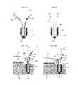
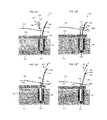
- FIGS. 12A-12Gare sequential views of one exemplary embodiment for using the surgical repair construct of FIG. 10 to secure tissue to bone;
- FIGS. 13A-13Dare sequential views of one exemplary embodiment for using the suture shuttle and anchor of FIG. 11 and the surgical repair construct of FIG. 9 to secure tissue to bone;
- FIGS. 14A-14Care sequential views of one exemplary embodiment for using a surgical repair construct to draw two tissues closer together;
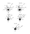
- FIGS. 15A-15Gare sequential views of one exemplary embodiment for using a surgical filament to secure an object
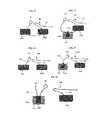
- FIG. 16is a schematic view of one exemplary embodiment of using a surgical filament to draw two tissues closer together;
- FIG. 17is a schematic view of one exemplary embodiment of using a surgical filament to draw a tissue closer to bone
- FIG. 18is a schematic view of one exemplary embodiment of using two surgical filaments to draw two tissues closer together;
- FIG. 19is a schematic view of one exemplary embodiment of using two surgical filaments to draw a tissue closer to bone;
- FIG. 20is a schematic view of another exemplary embodiment of using two surgical filaments to draw a tissue closer to bone;
- FIG. 21is a schematic view of one exemplary embodiment of using a surgical repair construct and a filament to draw a tissue closer to bone;
- FIG. 22is a schematic view of another exemplary embodiment of using a surgical repair construct and a filament to draw a tissue closer to bone.
- linear or circular dimensionsare used in the description of the disclosed systems, devices, and methods, such dimensions are not intended to limit the types of shapes that can be used in conjunction with such systems, devices, and methods. A person skilled in the art will recognize that an equivalent to such linear and circular dimensions can easily be determined for any geometric shape. Sizes and shapes of the systems and devices, and the components thereof, can depend at least on the anatomy of the subject in which the systems and devices will be used, the size and shape of components with which the systems and devices will be used, and the methods and procedures in which the systems and devices will be used.
- Systems, devices, and methods for soft tissue repairare generally provided and they generally involve the use of surgical filaments that are configured in a variety of manners to minimize and/or eliminate the tying of knots during a surgical procedure.
- the systems and devices described hereinprovide superior strength for use in a number of different surgical procedures, such as rotator cuff and instability repair procedures and other types of tendon and tissue repair procedures. They also allow for attachments that have a lower profile than existing systems and devices, which allows for the filaments to become associated with tissue, for instance by passing the filaments through the tissue or wrapping the filaments around the tissue, with minimal trauma to the tissue and less space being taken up by the overall construction. This results in systems and devices that can be associated with tissue atraumatically to secure the tissue in a knotless manner.
- the systems and devices provided hereinalso allow for both improved and new procedures for soft tissue repair.
- the systems and devices provided hereincan be used to advance tissue toward bone in an incremental fashion without the construct backlashing to cause the tissue to move away from the bone and/or to not be held tightly in place with respect to the bone.
- the present disclosureprovides for a number of different methods, some new and some improved, for fully securing objects, such as tissue and/or bone fragments, using a single filament and for securing tissue to bone or tissue to other tissue at desired locations using one or more filaments or repair constructs.
- the constructs of the present disclosuregenerally include a collapsible loop 20 having a first end 22 that is coupled to a snare linkage 40 and a second end 24 that includes a sliding knot 26 formed thereon.
- the snare linkage 40has a snare 46 at a first end 42 thereof and a second end 44 configured to receive the first end 22 of the loop 20 .
- the snare 46includes an opening 48 that is configured to receive the second end 24 of the loop 20 and collapse around the second end 24 after it is disposed in the opening 48 .
- the sliding knot 26 formed on the collapsible loop 20can be operable to collapse a size of an opening 28 formed by the loop 20 .
- the sliding knot 26can be movable toward the first end 22 to collapse the loop 20 , and it can also be movable away from the first end 22 to expand a size of the opening 28 .
- the collapsible loop 20 and the snare linkage 40are each formed by different surgical filaments.
- the collapsible loop 20can include two tails, a collapsible tail 30 , operable to move the sliding knot 26 towards the first end 22 in a ratchet-like or incremental manner, and a stationary terminal tail 32 configured to remain stationary with respect to the sliding knot 26 .
- the construct 10can be passed through one or more tissues such that passing the second end 24 through the snare 46 and both collapsing the snare 46 around the second end 24 and advancing the snare 46 distally (e.g., toward bone) can cause the tissue through which the construct 10 is disposed to be drawn toward a bone, an anchor, or other tissue to which the construct 10 is also coupled, as described in greater detail below. Because of the features of the constructs disclosed herein, many repair methods can be performed atraumatically and without tying knots to attach and move tissue to desired locations during the course of a surgical procedure.
- FIG. 2provides one exemplary embodiment of a snare linkage 140 for use as part of a surgical repair construct.
- a first end 142 of the snare linkage 140can include a snare 146 that is configured to collapse under tension
- a second end 144 of the snare linkage 140can be configured to slidably couple to a collapsible loop 120 of the construct to allow relative motion between the linkage 140 and the loop 120
- a connecting neck 150can extend between the two ends 142 , 144 .
- the connecting neck 150can be formed by a surgical filament having a coaxial sliding neck 152 that is slidable within a cannulated portion 154 of the connecting neck 150 .
- a person skilled in the artwill recognize that the coaxial sliding neck 152 moves with respect to the cannulated portion 154 , and thus although the movement is described herein based on the movement of the coaxial sliding neck 152 , the cannulated portion 154 can also be slid with respect to the coaxial sliding neck 152 .
- Passing the filament that forms snare linkage 140 through itself to form the coaxial sliding neck 152allows the snare linkage 140 to have a low profile that minimizes and/or eliminates the trauma associated with passing the snare linkage 140 through tissue, particularly in comparison to existing surgical repair constructs. Further, this construction can eliminate any sharp features that could be present in existing surgical repair constructs, which can present difficulties, including trauma, when trying to pass surgical repair constructs through tissue.
- FIGS. 3A-3Dillustrate one method of forming snare linkage 140 ′ having a snare 146 ′ and a coaxial sliding neck 152 ′ for use in a surgical repair construct.
- the snare 146 ′is formed from a bifurcated suture filament having a tubular portion 153 ′ with a core removed therefrom to form a cannulated portion 154 ′ and first and second terminal limbs 156 ′, 158 ′.
- the terminal limbs 156 ′, 158 ′can be curled back toward the tubular portion 153 ′ to form a loop having an opening 148 ′ that defines the snare 146 ′.
- a bore 160 ′can be formed on a side of the tubular portion 153 ′ and the terminal limbs 156 ′, 158 ′ can be placed into the cannulated tubular portion 154 ′ through the bore 160 ′. Ends of the terminal limbs 156 ′, 158 ′ can be fed through the cannulated portion 154 ′, and as shown in FIG. 3D , the terminal limbs 156 ′, 158 ′ can be pulled distally (direction C in FIG. 3D ) through the tubular portion 153 ′ such that the tubular portion 153 ′ is fed through itself.
- the snare 146 ′can be collapsed by tensioning the limbs 156 ′, 158 ′ in approximately a first direction C, and/or the coaxial portion of the tubular portion 153 ′ that extends outside of the connecting neck 150 ′, and the snare 146 ′ can be expanded by applying a force to the snare 146 ′ in approximately a second, opposite direction D, which pulls the limbs 156 ′, 158 ′ towards the snare 146 ′.
- the sizes of the components of the snare linkage 140 ′can depend, at least in part, on the procedure in which it is being used, the components with which it is being used, and other factors recognized by those skilled in the art.
- the overall length of the snare linkagecan be in the range of about 5 millimeters to about 50 millimeters, and in one embodiment it is about 36 millimeters.
- a length of the filament used to form the snare linkagecan be in the range of about 15 centimeters to about 125 centimeters, and in one embodiment it is about 60 centimeters.
- Snarescan also be formed in a number of other manners known to those skilled in the art.
- a number of different sliding knotscan be used to form the snare of the snare linkage, including but not limited to a Buntline Hitch, a Tennessee Slider, a Duncan Loop, and a Hangman's Noose.
- a knot used to form a snare in a snare linkageis movable away from a second end of the snare linkage, i.e., away from the collapsible loop, to collapse the snare and towards the second end, i.e., towards the collapsible loop, to increase a size of the snare.
- the snare linkagecan be made of a variety of materials, but in one exemplary embodiment the snare linkage is formed using a surgical filament, such as a cannulated filament, a braided filament, and a mono filament.
- a surgical filamentsuch as a cannulated filament, a braided filament, and a mono filament.
- the type, size, and strength of the filamentcan depend, at least in part, on the other materials of the system, including the material(s) of the collapsible loop with which it is used, the tissue and other components through which it will be passed or coupled to, and the type of procedure in which it is used.
- the snare linkageis formed from a #2 filament (about 23 gauge to about 24 gauge), such as an OrthocordTM filament that is commercially available from DePuy Mitek, Inc.
- the snare linkagecan have a size between about a #5 filament (about 20 gauge to about 21 gauge) and about a #3-0 filament (about 29 gauge to about 32 gauge).
- the OrthocordTM #2 filamentcan be useful because it has a braided configuration, which allows other components, such as flexible members or collapsible loops as discussed below, to pass through subcomponents of the braid without causing damage to the filament. Filaments configured to allow for a cannulated configuration, such as by removing a core therefrom or having a pre-formed cannulated configuration, can also be used to form the snare linkage.
- OrthocordTM sutureis approximately fifty-five to sixty-five percent PDSTM polydioxanone, which is bioabsorbable, and the remaining thirty-five to forty-five percent ultra high molecular weight polyethylene, while EthibondTM suture is primarily high strength polyester.
- the amount and type of bioabsorbable material, if any, utilized in the filaments of the present disclosureis primarily a matter of surgeon preference for the particular surgical procedure to be performed.
- a diameter of the snare opening in an uncollapsed positionis in the range of about 2 millimeters to about 15 millimeters, and in one embodiment it is about 10 millimeters while a length of the connecting neck when the snare is in an uncollapsed configuration is in the range of about 0 millimeters (excluding the length of the connecting neck) to about 45 millimeters (excluding the length of the connecting neck), and in one embodiment it is about 5 millimeters (excluding the length of the connecting neck).
- a length of the neck after the snare is collapsedcan be in the range of about 3 millimeters (excluding the length of the connecting neck) to about 45 millimeters (excluding the length of the connecting neck), and in one embodiment is about 27 millimeters (excluding the length of the connecting neck).
- a flexible membersuch as a suture pin
- a connecting neck 250includes a coaxially sliding neck 252 , such as in the snare 246 of a snare linkage 240 illustrated in FIG. 4
- a flexible member 270can extend across the neck 250 to immobilize the coaxially sliding neck 252 with respect to the connecting neck 250 .
- the flexible member 270can be removed.
- the use of a flexible member of the type described herein to prevent unintentional collapse of the snare in tissue repair proceduresis advantageous as it can allow the snare linkage to be passed atraumatically through tissue while still preventing unintentional collapse of a snare.
- a flexible member 370can both immobilize a snare 346 of a snare linkage 340 and serve as a suture shuttle to guide the snare linkage 340 through obstructions during the course of a procedure.
- a first end 372 of the flexible member 370can be passed across connecting and coaxial necks 350 , 352 of the snare linkage 340 so that a first portion of the flexible member 370 is disposed through the neck 350 , while a second end 374 of the flexible member 370 is passed through and disposed in the snare 346 .
- a protrusion 376for instance a stationary knot that can be pre-formed or formed or modified during a procedure, can be disposed on the flexible member 370 at a location between the first and second ends 372 , 374 .
- the protrusion 376can serve to maintain the flexible member 370 in a coupled arrangement with the snare linkage 340 , and as shown in FIG. 5B , the protrusion 376 can be disposed within the opening or loop 348 formed by the snare 346 , abutting a surface of the snare, with a terminal portion 378 extending through and beyond the loop 348 for use as a shuttle.
- a needle or similar tool or devicecan be coupled to the terminal portion 378 to assist in threading the snare linkage 340 through tissue.
- a flexible memberis used as both a suture pin and a suture shuttle
- the flexible member 370can be disposed through another portion of the connecting neck 350 or a different portion of the snare 346 .
- One benefit of using a flexible member for both maintaining a snare shape and shuttling the snare linkageis that it can improve filament management by limiting the number of filaments used in a procedure.
- such a constructionallows for a single action to remove both the pin and the shuttle from the linkage, such as applying tension to a second terminal end 379 of the flexible member 370 to decouple the flexible member 370 from the snare linkage 340 .
- a flexible membercan be used primarily for the purpose of shuttling the snare linkage through obstructions.
- FIGS. 6 and 7illustrate two examples of ways a flexible member 470 , 470 ′ can be coupled to a snare linkage 440 , 440 ′ for shuttling purposes. As shown in FIG. 6 , the flexible member 470 is passed across a top portion 447 of the snare 446 , with a protrusion 476 being formed on the flexible member 470 to maintain a coupling between the flexible member and the snare assembly during shuttling.
- the protrusion 476can be disposed within the opening or loop 448 , abutting a surface of the loop, with a terminal portion 478 extending through and beyond the loop 448 for use as a shuttle.
- a needle or similar tool or devicecan optionally be coupled to the terminal portion 478 to assist in threading the snare linkage 440 through tissue.
- a first flexible member 470 ′is coupled to a snare linkage 440 ′ by looping the flexible member 470 ′ through a snare 446 ′, and a second flexible member 471 ′ is disposed across a connecting neck 450 ′ to immobilize the neck 450 ′ while the snare linkage 440 ′ is being shuttled through obstructions.
- tension applied to the first flexible member 470 ′ in approximately a direction F to shuttle the snare linkage 440 ′ through obstructionswould cause the size of the snare opening 448 ′ to decrease.
- the flexible member(s) for any of the embodiments described hereincan be made of a variety of materials, but in one exemplary embodiment it is a surgical filament that is separate from the surgical filament that forms the snare linkage. In some embodiments the flexible member is formed using a surgical filament, such as a cannulated filament, a braided filament, and a mono filament.
- the type, size, and strength of the filamentcan depend, at least in part, on the other materials of the system, including the material(s) of the neck through which it will pass, the obstructions through which the snare will pass, how the filament is being used (e.g., as a suture pin, as a suture shuttle, or as a joint suture pin and suture shuttle), and the type of procedure in which it is used.
- the flexible memberis formed from a #2-0 filament (about 28 gauge), such as an OrthocordTM filament that is commercially available from DePuy Mitek, Inc. or EthibondTM filament available from Ethicon Inc.
- the flexible memberis relatively thin to minimize any trauma to tissue through which it passes, and typically the flexible member is thinner than the snare linkage.
- the flexible membercan have a size between about a #1 filament (about 25 gauge to about 26 gauge) and about a #6-0 filament (about 38 gauge to about 40 gauge).
- a length of the flexible membercan be in the range of about 1 centimeter to about 100 centimeters. In one embodiment in which the flexible member is only being used as a suture pin it can have a length of about 1 centimeter. In one embodiment in which the flexible member is used as both a suture pin and a suture shuttle it can have a length of about 50 centimeters. In one embodiment in which the flexible member is only being used as a suture shuttle it can have a length of about 100 centimeters.
- FIGS. 2 and 8Two such embodiments are shown in FIGS. 2 and 8 .
- the second end 144 of the snare linkage 140includes an eyelet 180 configured to receive the collapsible loop 120 .
- the eyelet 180is generally circular in shape, and can generally have a substantially fixed diameter.
- the eyelet 180can be formed in any number of ways, but in one embodiment in which the snare linkage 140 is formed from a cannulated or braided surgical filament, a first portion 182 of the filament can be passed through a second portion 184 to form the eyelet 180 , similar to the formation of the snare 146 at the first end 142 . However, to maintain a substantially fixed diameter, the first portion 182 , which serves as a coaxially sliding neck, can be fixed with respect to the second portion 184 , which serves as an outer neck. Any number of techniques can be used to fix the location of the sliding neck 182 , including using an adhesive, heat bonding the filament, or disposing a pin or other fasteners thereacross.
- a size of the eyeletcan depend, at least in part, on the other components of the construct, the obstructions through which the snare linkage will pass, and the type of procedure in which it is used, a diameter of the eyelet can be in the range of about 1 millimeter to about 10 millimeters, and in one embodiment it is about 3 millimeters.
- FIG. 8provides an alternative configuration for a second end 544 of a snare linkage 540 .
- a collapsible loop 520is coupled to the snare linkage 540 by passing the loop 520 through the filament at the second end 544 .
- the filament that forms snare linkage 540can be a cannulated filament, a braided filament, or a mono filament that enables the loop 520 to pass through the filament and maintain a sliding engagement therewith without causing damage to filament of the snare linkage 540 or the loop 520 .
- second end 544 of the filamentcan be treated to prevent unintended fraying.
- the second end of the filamentcan be heat bonded, coated, or otherwise treated to prevent fraying.
- Alternative configurations and materials beyond those provided in FIGS. 2 and 8can also be used by those skilled in the art to allow for a sliding engagement between the second end of the linkage and the collapsible loop.
- the snareis part of a separately formed snare linkage
- a single filamentcan be used to form both the snare and the collapsible loop.
- Other techniquescan also be used to form the snare and loop, including those discussed in U.S. patent application Ser. No. 13/218,810 filed Aug. 26, 2011, and entitled “SURGICAL FILAMENT SNARE ASSEMBLIES,” the content of which is incorporated by reference herein in its entirety.
- the collapsible loop 20 illustrated in FIG. 1can generally be a flexible elongate member having a first end 22 coupled to the snare linkage 40 and a second end 24 closed by a sliding knot 26 .
- the sliding knot 26allows the loop 20 to be collapsed as desired, and thus when a portion of the loop 20 is coupled to or passed through tissue, collapsing the loop 20 can tension the tissue to draw it toward a desired location. As shown in FIG. 1 , as the knot 26 is moved toward the first end 22 , the loop 20 collapses, and as the knot 26 is moved away from the first end 22 , the size of the opening 28 of the loop 20 increases.
- the sliding knot 26can be formed in a variety of ways using a variety of techniques well known to those skilled in the art.
- Non-limiting examples of the types of knots that can be used as the loop's sliding knotinclude a Buntline Hitch, a Tennessee Slider, a Duncan Loop, a Hangman's Noose, and a loop having a coaxial sliding neck.
- the loop 20can also have a collapsible tail 30 and a stationary terminal tail 32 that extend from the sliding knot 26 .
- the tails 30 , 32can be terminal ends of two limbs of a filament used to form the sliding knot 26 that completes the collapsible loop 20 .
- the collapsible tail 30can be operable to tension and collapse the loop 20 by moving the sliding knot 26 towards the loop first end 22 . More particularly, applying tension to the collapsible tail 30 in approximately the direction E can cause the knot 26 to slide distally toward the first end 22 .
- the sliding knot 26can move in a ratchet-like or incremental fashion such that the knot 26 moves toward the first end 22 without backlashing and causing the collapsible loop 20 to increase in size.
- the location of the sliding knot 26remains substantially fixed, and further tensioning of the collapsible tail 30 can cause further distal movement of the knot 26 until either the tension is released or an obstruction precludes further distal movement of the knot 26 .
- the self-locking capabilities provided by this sliding knot 26 that result from the overall formation of the construct 10are beneficial at least because of the ability to incrementally advance the knot 26 without backlashing.
- the stationary terminal tail 32is adjacent to the collapsible filament tail 30 and is stationary with respect to the sliding knot 26 .
- the stationary terminal tail 32is shorter than the collapsible tail 30 , but in other instances it can be the same length as or even longer than the collapsible tail 30 .
- a longer stationary tail 32can provide some beneficial aspects.
- a long stationary tail 32can be used as a suture shuttle to pass the collapsible loop 20 through tissue. Using the stationary tail 32 as a shuttle can prevent a premature collapse of the loop 20 .
- a needle or similar tool or devicecan optionally be coupled to the stationary tail 32 to assist in threading the tail 32 through tissue.
- one or more half-hitchescan optionally be formed on the stationary tail 32 to provide additional system strength. Such half-hitches can also be formed on the collapsible tail 30 if desired for additional strength. Still further, longer stationary and collapsible tails 32 , can be used in conjunction with other types of procedures, such as double row procedures, as described in greater detail below.
- the flexible loopcan be made of a variety of materials, but in one exemplary embodiment it is a surgical filament.
- the surgical filament that forms the collapsible loopis typically a separate filament than what is used to form the snare linkage or the flexible member.
- the filament of the collapsible loopcan be any suitable suture material such as a cannulated filament, a braided filament, and a mono filament.
- the type, size, and strength of the filamentcan depend, at least in part, on the other materials of the system, including the materials of any snare linkage or bone anchor with which the loop may be associated, the obstructions through which the loop will pass, and the type of procedure in which it is used.
- the flexible loopis formed from a #0 filament (about 26 gauge to about 27 gauge), such as an OrthocordTM filament that is commercially available from DePuy Mitek, Inc or EthibondTM filament available from Ethicon, Inc.
- a #0 filamentabout 26 gauge to about 27 gauge
- the collapsible loopis relatively thin to minimize any trauma to tissue through which it passes, and can typically the loop is thinner than the snare linkage.
- the collapsible loopcan have a size between about a #4 filament (about 21 gauge to about 22 gauge) and about a #4-0 filament (about 32 gauge to about 34 gauge).
- a length of the loop in its uncollapsed configurationcan be in the range of about 2 centimeters to about 60 centimeters, and in one embodiment it can be about 40 centimeters. Still further, a diameter of the sliding knot of the loop will depend, at least in part, on the size of the filament used to form it, the type of sliding knot that it is, and the type of procedure with which it will be used. In one exemplary embodiment a diameter of the sliding knot can be in the range of about 0.5 millimeters to about 3 millimeters, and in one embodiment it can be about 1 millimeter.
- a flexible sleevecan be provided for encapsulating at least a portion of a collapsible loop.
- a sleeve 690can be disposed around collapsible and stationary terminal tails 630 , 632 , a sliding knot 626 , and a portion of the loop 620 at a second end 624 , extending toward a first end 622 .
- the sleeve 690can have a generally cylindrical configuration and can be flexible to allow it to bend as shown in various embodiments provided herein.
- the sleeve 690can be useful when passing the construct 610 through obstructions such as tissue for a number of reasons.
- the sleeve 690can protect the knot 626 from being unintentionally tightened when it passes through an obstruction. Further, the sleeve 690 can be configured to have a smoother surface that is better configured to pass through tissue than a knot, thus easing trauma caused by passing the construct 610 through tissue. Still further, because the sleeve 690 can encapsulate a plurality of filament limbs, the sleeve 690 can ease filament management by maintaining the filaments within the enclosed sleeve 690 .
- the sleeve 690can be removable, and it is typically removed prior to collapsing the loop 620 so that the sleeve 690 does not interfere with movement of the sliding knot 626 .
- FIG. 9illustrates only one of many possible configurations of which portions of the construct 610 can be encapsulated by the sleeve 690 .
- one or both of the collapsible and stationary terminal tails 630 , 632can extend beyond the sleeve 690 .
- the sleeve 690can extend a length beyond terminal ends of the collapsible and stationary terminal tails 630 , 632 such that a portion of the sleeve 690 is empty.
- a configuration of this naturecan aid a surgeon in pulling the construct 610 through a portion of the body by providing extra length onto which he or she can grasp.
- the sleeve 690can extend outside of a body and a cannula placed in the body once the construct 610 is implanted so the sleeve 690 can be easily removed.
- the sleevecan be made from a wide variety of biocompatible flexible materials, including a flexible polymer or it can be another filament.
- the sleeveis made of a polymeric material.
- the sleeveis a flexible filament, such as a braided suture, for example EthibondTM #0 filament or OrthocordTM #2 filament, which is typically braided at sixty picks per 2.54 centimeters.
- a more relaxed braid of approximately thirty to forty picks per 2.54 centimetersis preferred, more preferably about 36 picks per 2.54 centimeters.
- the sleeve materialis formed about a core, preferably that core is removed to facilitate insertion of the filament limbs, which may themselves be formed of typical suture such as OrthocordTM #0 suture or #2 suture braided at sixty picks per 2.54 centimeters. Additional convenience can be provided by perceptible indicators on the sleeve such as different markings, colors, diameters, braid or design patterns, or other tactile or visual indicia, especially if multiple tissue attachments or anchors are utilized.
- a length and diameter of the sleevecan depend, at least in part, on the size and configuration of the components of the construct with which it is used, the obstructions through which the sleeve may pass, and the surgical procedure in which it is used.
- the sleeveis typically of a size such that it can pass atraumatically through tissue.
- a size of the sleevecan be in the range of about a #5 filament (about 20 gauge to about 21 gauge) to about a #2-0 filament (about 28 gauge), and in one embodiment the size can be about a #0 filament (about 26 gauge to about 27 gauge).
- the sleevecan have a length in the range of about 10 centimeters to about 60 centimeters, and in one embodiment it has a length of about 40 centimeters.
- FIG. 10illustrates one exemplary embodiment of the repair construct 610 of FIG. 9 coupled to a bone anchor 608 .
- anchor 608is a Healix TiTM anchor that is commercially available from DePuy Mitek, Inc.
- the anchor 608can include a filament engagement feature 609 , which can be on any part of the anchor, but in the exemplary embodiment is at a distal end 608 d of the anchor 608 and allows the construct 610 to be slidably engaged with the anchor 608 .
- the construct 610should be slidingly coupled to the anchor 608 by way of the filament engagement feature 609 such that the snare linkage 640 extends from one side of the anchor 608 and the sliding knot 626 extends from the other side of the anchor 608 .
- the use of this construct 610is described below with respect to FIGS. 12A-12G .
- FIG. 11illustrates one exemplary embodiment of a suture shuttle 800 coupled to a bone anchor 708 .
- the illustrated anchor 708is a Healix TiTM anchor that is commercially available from DePuy Mitek, Inc.
- the anchor 708can include a filament engagement feature 709 , which can be at a distal end 708 d of the anchor 708 and which allows the shuttle 800 to be slidably engaged with the anchor 708 .
- the shuttle 800is slidingly coupled to the anchor 708 at the filament engagement feature 709 such that a first end 802 of the shuttle 800 extends from one side of the anchor 708 and a second end 804 of the shuttle 800 extends from the other side of the anchor 708 .
- the first end 802can be configured to be coupled to a repair construct, such as the repair construct 610 of FIG. 9 .
- the first end 802includes a collapsible snare 806 , but any other suitable coupling mechanism can be used at the first end 802 without departing from the spirit of the present disclosure.
- the first end 802can include a clip or a like element to clamp around a repair construct.
- the second end 804can be used to position the repair construct 610 in a desired location as described below with respect to FIGS. 13A-13D .
- FIGS. 12A-12GOne exemplary embodiment of a method for performing a rotator cuff repair using the repair construct illustrated in FIG. 10 is illustrated in FIGS. 12A-12G .
- a surgical openingcan be formed through skin 1000 and a cannula can be passed therethrough to create a surgical repair site in a manner well known to those skilled in the art.
- cannulasare often used to define a channel through which the procedure can be performed, the cannula is not shown in FIGS. 12A-12G for ease of illustration. Accordingly, to the extent the figures show components of the systems and devices passing through skin 1000 , these components would typically be extending through the cannula, which itself is passed through the skin 1000 .
- the devices and methods described hereinare particularly useful for minimally invasive surgery, such as arthroscopic surgery, they can also be used in open surgical procedures.
- the anchor 608 shown in FIG. 10can be fixated into bone 1001 using ordinary techniques, such as with a driver to screw or tap the anchor 608 into place.
- the construct 610which includes a flexible member 670 that serves as both a suture pin and a shuttle, is already coupled thereto, although in other embodiments the construct 610 can be slidingly coupled to the anchor 608 after the anchor 608 is positioned at its desired location.
- a terminal portion 679 of the flexible member 670can be passed into and through tendon 1003 detached from bone 1001 to pull the snare linkage 640 , and a portion of the collapsible loop 620 , through the tendon 1003 .
- a needle or similar tool or devicecan be coupled to the terminal portion 679 to assist with threading the construct 610 through the tendon 1003 .
- other shuttling techniquesincluding those described herein and those known to a person skilled in the art, can also be used to pass the snare linkage 640 through and/or around the tendon 1003 .
- the other end of the construct 610 on which the sliding knot 626 is disposedcan also pass through the tendon 1003 at a second location on the tendon 1003 .
- the optional sleeve 690can be disposed around the limbs 630 , 632 , the sliding knot 626 , and a portion of the loop 620 , thereby easing any trauma caused by passing this portion of the construct 610 through the tendon 1003 and assisting with management of the filament limbs.
- the snare linkage 640that has been passed through the tendon 1003 at a first location and is accessible to the surgeon outside of the body
- the sliding knot 626that has been passed through the tendon 1003 at a second location and is accessible to the surgeon outside of the body.
- a portion of the loop second end 624can be passed through the snare 646 such that the snare 646 is distal of the sliding knot 626 , thereby allowing the tendon 1003 through which the construct 610 is disposed to be captured.
- the flexible member 670can be removed from the snare linkage 640 , and the snare 646 can be collapsed or dressed around the portion of the second end 624 that is disposed therethrough, with the snare 646 remaining distal of the sliding knot 626 .
- the flexible member 670can actually be removed from the snare linkage 640 any time after it has been passed through any tissue such that its purposes of serving as a shuttle for the construct 610 and a pin to prevent unintentional collapse of the snare 646 are no longer desired.
- tensioncan be applied to the second end 624 by pulling approximately in a direction G, thereby causing the collapsed snare 646 to slide distally toward the tendon 1003 in a zip-line like manner until the snare 646 is adjacent to the tendon 1003 .
- tensioncan be applied to the second end 624 before the snare 646 is dressed and after the snare 646 is adjacent to the tendon 1003 , or some combination of the two actions can be used, such as partially dressing the snare 646 before zip-lining it toward the tendon 1003 .
- FIG. 12Etension can be applied to the second end 624 by pulling approximately in a direction G, thereby causing the collapsed snare 646 to slide distally toward the tendon 1003 in a zip-line like manner until the snare 646 is adjacent to the tendon 1003 .
- tensioncan be applied to the second end 624 before the snare 646 is dressed and after the snare 646 is adjacent to
- a sleeve 690is included as part of the construct 610 , it can be removed once it is used to assist in passing the second end of the construct 610 through tissue. However, it can be helpful to keep the sleeve 690 disposed around a portion of the loop second end 624 to prevent unintentional movement of the knot 626 , to continue helping to manage filament limbs, and to help in zip-lining the snare 646 toward the tendon 1003 because there is typically less friction created by the sleeve 690 as opposed to the filament that the sleeve 690 encapsulates. As shown in FIG.
- the sleeve 690can be removed from the construct 610 to expose the sliding knot 626 and the collapsible tail 630 .
- Tensioncan be applied to the collapsible tail 630 by pulling approximately in the direction H, thereby causing the knot 626 to advance distally towards the tendon 1003 so that it can be adjacent to the snare 646 and in turn bring the tendon 1003 into proximity with the bone 1001 , as shown in FIG. 12G .
- the configuration of the construct 610allows the knot 626 to be advanced in an incremental, ratchet-like fashion when the collapsible tail 630 is pulled in the direction H without the risk of reversing the progress of the knot 626 as a result of slipping backward, sometimes referred to as backing out, backlashing, or slackening of the filament.
- the snare 646 and the loop 620can be collapsed at the same time by applying tension to the collapsible tail 630 approximately in the direction H.
- one or more half-hitches 631can be added to the filament adjacent to the sliding knot 626 to provide additional strength once the filaments have been finally positioned to approximate tissue.
- the half-hitches 631can be formed on either or both of the collapsible and stationary terminal tails 630 , 632 .
- the formation of one or more half-hitchescan hinder the ability for the collapsible tail 630 to provide the incremental movement of the sliding knot 626 . Accordingly, in instances in which multiple constructs are used together as part of a procedure, it may be desirable to add half-hitches only after all constructs have been placed, deployed, and tensioned as desired. Other than the optional half-hitches, no knots need to be tied during the course of the illustrated procedure.
- the stitch pattern resulting from the methods and shown in FIG. 12Gis a mattress stitch pattern, but a person skilled in the art would be able to use other desired stitch patterns without departing from the spirit of the present disclosure.
- the resulting break strength of the formed stitchcan be in the range of about 130 Newtons to about 225 Newtons without the formation of any half-hitches, and in one embodiment the break strength can be about 156 Newtons without the formation of any half-hitches. The use of half-hitches typically increases the load capacity.
- the stationary terminal tail 632is short, in other embodiments it can be longer for reasons described above and for other procedures.
- at least one half-hitchcan be added to the stationary terminal tail 632 and then the remaining length of the tail 632 can be used for medial row fixation in a double row procedure such that two tails 630 , 632 can be spanned over to medial row anchor(s).
- a collapsing tail 630can be spanned over to a lateral row anchor without locking the repair construct with an additional half-hitch. In this instance, however, the medial and lateral row fixations would not be independent of each other.
- FIGS. 12A-12Gcan include slidably coupling multiple repair constructs to the same anchor, which would provide the ability to incrementally and independently tension each construct with respect to the same anchor. Accordingly, a new repair technique can be implemented in which the tension on the whole repair construct can be tailored incrementally to eliminate undesired blemishes such as puckering and the formation of “dog-ears.”
- multiple anchors, each having one or more repair constructs slidably coupled thereto,can be disposed at the surgical site and again incremental repair can be tailored for a more desirable result.
- FIGS. 13A-13DOne exemplary embodiment of a method for performing a rotator cuff repair using the repair construct illustrated in FIGS. 9 and 11 is illustrated in FIGS. 13A-13D .
- a surgical openingcan be formed through skin 1000 and a cannula can be passed therethrough to create a surgical repair site according to well known techniques. Similar to FIGS. 12A-12G , although cannulas are often used to define a channel through which the procedure can be preformed, the cannula is not shown in FIGS. 13A-13D for ease of illustration. Accordingly, to the extent the figures show components of the systems and devices passing through skin 1000 , these components would typically be extending through the cannula, which itself is passed through the skin 1000 .
- the anchor 708 shown in FIG. 11can be fixated into bone 1001 using ordinary techniques, such as by using a driver to screw or tap the anchor 708 into place.
- the suture shuttle 800which includes the first end 802 having the snare 806 formed therein, is already coupled thereto, although in other embodiments the suture shuttle 800 can be slidingly coupled to the anchor 708 after the anchor 708 is positioned at its desired location.
- the first and second ends 802 , 804 of the suture shuttle 800can be passed through detached soft tissue, such as tendon 1003 .
- a portion of the repair construct 610 of FIG. 9can be passed through the snare 806 .
- the snare 806can then be collapsed, thereby coupling the repair construct 610 to the shuttle 800 .
- the snare 806is the mechanism used to couple the shuttle 800 and the construct 610 , a variety of other coupling techniques can also be used to couple the repair construct 610 to the suture shuttle 800 .
- a force approximately in the direction Jcan then be applied to the second end 804 to pull the first end 802 , and thus the repair construct 610 , through the tendon 1003 at a first location, around the filament engagement feature 709 , and through the tendon 1003 at a second location.
- the snare linkage 640can be disposed on one side of the anchor 708 and the sliding knot 626 can be disposed on the other side of the anchor 708 , with the collapsible loop 620 being slidingly engaged with the filament engagement feature 709 .
- the optional, removable sleeve 690can be particularly useful in this embodiment because the knot 626 passes through the tendon 1003 twice, and also around the anchor 708 , and thus the less friction and suture management capabilities it affords can be helpful. Further, once the shuttle 800 has moved the construct 610 to the desired location, the shuttle 800 can be de-coupled from the repair construct 610 . Once the construct 610 is in place as illustrated in FIG. 13D , the construct 610 can be operated in a manner similar to as described with respect to FIGS. 12D-12G .
- the anchor 708can include multiple suture shuttles coupled thereto to allow for multiple repair constructs that can be independently and sequentially deployed to be used in a surgical procedure.
- a surgeoncan use a single shuttle to install multiple constructs on the same anchor, or still further, multiple anchors can be fixated for a procedure with each having its own repair construct or shuttle, or one suture shuttle can be used to place one or more constructs at multiple anchors.
- the construct 610is passed through two portions of tendon 1003
- the construct 610can be passed through only one portion of tendon or tissue while the second portion of the construct 610 can be free of the tendon or tissue.
- Either of the two endscan be the end that is not passed through the tendon or tissue, however, if a snare linkage 640 is not passed through tissue, a flexible member 670 to serve as a suture pin can be omitted and can be replaced, if desired, by any technique or mechanism used to prevent unintentional collapse of the snare 646 , such as a spacer or tube.
- a repair constructcan be coupled to tissue using other techniques, such as, for example, by wrapping the construct around the tissue.
- a repair constructcan be used to pull two or more tissues into proximity with each other. Any of the repair constructs provided herein, or derivations thereof, can be used in conjunction with techniques of this nature. As shown in FIG. 14A , a repair construct 710 includes a collapsible snare 746 having a filament member 770 that is operable as both a suture pin and a suture shuttle, with two terminal limbs 756 , 758 extending from a tubular portion 753 .
- a terminal portion 779 of the flexible member 770can be passed through a first tissue 2003 , optionally using a needle or similar tool or device coupled to the terminal portion 779 to assist with threading the flexible member 770 through the first tissue 2003 , to pull the snare 746 and a portion extending distally from the snare 746 through the first tissue 2003 , as shown in FIG. 14B .
- the terminal limbs 756 , 758can be passed through a second tissue 2005 , also optionally using a needle or similar tool or device for each limb 756 , 758 to assist with threading the limbs 756 , 758 through the second tissue 2005 .
- both the snare 746 and the two terminal limbs 756 , 758are on a superior side of the tissue 2003 , 2005 , at least a portion of the limbs 756 , 758 can be passed through the snare 746 , as shown in FIG. 14C , and then the snare 746 can be dressed to secure the two pieces of tissue 2003 , 2005 together.
- the limbs 756 , 758can be subsequently tensioned to pull the two tissues 2003 , 2005 closer together.
- FIGS. 14A-14Cis directed to pulling together two tissues 2003 , 2005 , a person skilled in the art would be able to adapt these techniques for three or more tissues by passing the repair construct, or repair constructs, through additional tissue that is desired to be involved.
- FIGS. 15A-15GOne example is illustrated in FIGS. 15A-15G .
- a flexible surgical filament 810 for use in a procedurecan be provided, with the filament 810 including a first end 812 having a snare 816 formed therein and a second, leading end 814 .
- the snare 816can be formed in a variety of ways, including using techniques provided herein, as well as other known techniques.
- the leading end 814can likewise have a variety of configurations, including having multiple limbs as provided in other embodiments of filament repair constructs disclosed herein, but as shown the leading end 814 is a single limb.
- the filament 810can be positioned substantially around an object 3000 , such as tissue or bone fragments, to form a first loop 811 , and the leading end 814 can be folded such that a portion thereof is substantially U-shaped.
- the filament 810can be preformed at the leading end 814 to have a substantially U-shaped configuration.
- the leading end 814can be moved approximately in the direction K such that at least a portion of the substantially U-shaped leading end 814 passes through the snare 816 , as shown in FIG. 15C .
- a portion of the leading end 814remains on a first side of the snare 816 and a second loop 813 is formed by the portion of the filament that is within the snare 816 , the second loop 813 being on the other side of the snare 816 .
- the snare 816can be collapsed or dressed using techniques appropriate for the type of snare that is formed in the filament 810 . Collapsing the snare 816 secures the first and second loops 811 , 813 , with the first loop 811 completely surrounding the object 3000 and the second loop 813 being adjacent to the object 3000 . As shown in FIG. 15E , the first loop 811 can then be collapsed around the object 3000 such that the loop 811 engages and holds the object 3000 . The first loop 811 can be collapsed, for example, by pushing the collapsed snare 816 , which operates as a sliding knot, towards the object 3000 in the direction L.
- the collapsed snare 816can be pushed using a knot pushing device, by hand, or by other techniques and mechanisms for advancing collapsed snares and sliding knots.
- the collapsed snare 816can be advanced in the direction L until no further tension can be provided and thus the filament of the first loop 811 is as fully engaged with the object 3000 as possible.
- the leading end 814can be passed through the second loop 813 .
- tensioncan be applied to the leading end 814 in a direction M to collapse the second loop 813 , as shown in FIG. 15G .
- the collapse of the second loop 813results in a more secure hold of the object 3000 at least because it locks the previously collapsed snare 816 in place and provides additional load-bearing strength without adding half-hitches.
- the object 3000is thus firmly and securely grasped by the filament 810 and can be moved and/or used as part of any number of surgical procedures.
- FIGS. 16-22illustrate a sampling of other procedures that can be performed in view of the systems and devices disclosed herein.
- FIGS. 16-22illustrate a sampling of other procedures that can be performed in view of the systems and devices disclosed herein.
- the various types of snares, loops, filaments, and repair constructs provided for hereincan be used in conjunction with these procedures.
- the procedures illustratedare not limited to being preformed by only the systems and devices illustrated in FIGS. 16-22 .
- the filamentsare shows as being disposed in tissue, other techniques for associating tissue and filaments can be used, including wrapping the filaments around the tissue.
- FIG. 16illustrates a filament 910 having a snare 916 and leading end 914 like the surgical filament 810 of FIGS. 15A-15G .
- the filament 910is disposed through two separate tissues 3003 , 3005 , for instance by passing the leading end 914 through both tissues 3003 , 3005 , or by passing the snare 916 through one tissue 3003 and passing the leading end 914 through the other tissue 3005 .
- the leading end 914can then be folded into a substantially U-shaped configuration and the filament 910 can be operated in a manner similar to as described with respect to FIGS. 15A-15G .
- a second loopcan be formed by collapsing the snare 916 around the leading end 914 .
- the collapsed snare 916can be advanced towards the tissue 3003 , 3005 to draw the tissue 3003 , 3005 closer together. Further, the second loop can be advanced distally by applying tension to the leading end 914 , which can assist in maintaining the location of the collapsed snare 916 , and thus the tissue 3003 , 3005 .
- FIG. 17is similar to FIG. 16 except one of the tissues includes an anchor 3008 fixated in bone 3001 .
- the filament 910 ′is passed through the tissue 3005 and through a connecting mechanism 3009 of the anchor 3008 in the bone 3001 .
- the connecting mechanism 3009can be any number of components used in bone anchors to allow suture to be coupled thereto, including but not limited to eyelets, posts, and other filament engagement features.
- a second loopcan be formed by collapsing the snare 916 ′ around the leading end 914 ′.
- the collapsed snare 916 ′can be advanced distally to draw the tissue 3005 closer to the bone 3001 .
- the second loopcan be advanced distally by applying tension to the leading end 914 ′, which can assist in maintaining the location of the collapsed snare 916 ′, and thus the tissue 3005 with respect to the bone 3001 .
- FIGS. 18 and 19are similar to FIGS. 16 and 17 , respectively, except rather than using a single filament 910 , 910 ′, two filaments 1010 , 1010 ′ and 1011 , 1011 ′ are used.
- One filament 1010 , 1010 ′includes the snare 1016 , 1016 ′ and the second filament 1011 , 1011 ′ includes the portion 1014 , 1014 ′ previously described as a leading end.
- the first filament 1010 , 1010 ′is associated with tissue 3003 ( FIG. 18 ) or an anchor 3008 fixated in bone 3001 ( FIG. 19 ) and a second filament 1011 , 1011 ′ is associated with tissue 3005 ( FIGS. 18 and 19 ).
- a second loopcan be formed by collapsing the snare 1016 , 1016 ′ around the second filament portion 1014 , 1014 ′.
- the collapsed snare 1016 , 1016 ′can be advanced distally to draw the tissue 3005 closer to tissue 3003 or the bone 3001 .
- the second loopcan be advanced distally by applying tension to the portion 1014 , 1014 ′, which can assist in maintaining the location of the respective components 3001 , 3003 , 3005 , and 3008 coupled to the filaments 1010 , 1010 ′ and 1011 , 1011 ′.
- FIG. 20illustrates another embodiment in which two filaments 1110 , 1111 are used to draw tissue 3005 closer to an anchor 3008 disposed in bone 3001 .
- the operation of this constructcan be similar to those described above with respect to FIGS. 15A-19 .
- a first filament 1110 having a snare 1116 and a terminal end 1115is coupled to an anchor 3008 fixated in bone 3001 .
- the anchor 3008can include a one-way sliding mechanism 3009 to allow the terminal end 1115 to be used as a tensioning tail to collapse the snare 1116 .
- the second filament 1111can be coupled to the tissue 3005 , the second filament 1111 having a leading end 1114 that can be folded to have a substantially U-shaped configuration.
- the leading end 1114can be disposed in the snare 1116 and the snare can be collapsed to form a second loop.
- the collapsed snare 1116can be advanced distally to draw the tissue 3005 towards the bone 3001 , for instance by applying tension to the terminal end 1115 .
- the second loopcan be advanced distally by applying tension to the leading end 1114 , which can assist in maintaining the location of the tissue 3005 with respect to the bone 3001 .
- Final tensioningcan be carried out by applying tension to the terminal end 1115 .
- FIGS. 21-22illustrate yet two further embodiments of constructs for use for drawing tissue to bone, the operation of which can be similar to those described above with respect to FIGS. 15A-20 .
- FIG. 21includes a first filament 1210 having a first end 1212 configured to couple to a repair construct 1310 and a second leading end 1214 , with the first end 1212 being coupled to an anchor 3008 disposed in bone 3001 and the second end 1214 being disposed through tissue 3005 .
- a second filamentforms a repair construct 1310 having a collapsible loop 1320 , a snare 1346 , and a connecting neck 1350 disposed therebetween.
- the loop 1320includes a sliding knot 1326 and has a collapsible tail 1330 operable to collapse the loop 1320 by moving the knot 1326 distally toward the anchor 3008 .
- the collapsible tail 1330can advance the sliding knot 1326 in a ratchet-like or incremental fashion.
- the leading end 1214can be folded to have a substantially U-shaped portion, which can be passed through the snare 1346 .
- the snare 1346can be collapsed around the leading end 1214 to form a second loop.
- the sliding knot 1326can be advanced distally, for instance by tensioning the tail 1330 in a direction N, thereby drawing the tissue 3005 toward the bone 3001 .
- the second loopcan be advanced distally by applying tension to the leading end 1214 , which can assist in maintaining the location of the sliding knot 1326 , and thus the tissue 3005 with respect to the bone 3001 .
- Final tensioningcan be carried out by applying tension to the collapsible tail 1330 .
- the method illustrated in FIG. 22is similarly operated as the method described with respect to FIG. 21 , but the collapsible loop 1320 ′ of the repair construct 1310 ′ is coupled directly to the anchor 3008 .
- a first filament 1210 ′is coupled to the repair construct 1310 ′ by collapsing the snare 1346 ′ around the leading end 1214 ′ of the first filament 1210 ′ disposed therein, collapsing the loop 1320 ′ draws the tissue 3005 towards the bone 3001 in which the anchor is disposed.
- FIGS. 21 and 22could also be used in conjunction with multiple tissues and no anchors and bone, and any of the methods of FIGS. 16-22 can be used with any number of components being drawn together, such as anchors, bone, and tissue, including more than two components, as well as any number of filament construct combinations without departing from the spirit of the present disclosure.
Landscapes
- Health & Medical Sciences (AREA)
- Surgery (AREA)
- Life Sciences & Earth Sciences (AREA)
- Biomedical Technology (AREA)
- Nuclear Medicine, Radiotherapy & Molecular Imaging (AREA)
- Engineering & Computer Science (AREA)
- Rheumatology (AREA)
- Heart & Thoracic Surgery (AREA)
- Medical Informatics (AREA)
- Molecular Biology (AREA)
- Animal Behavior & Ethology (AREA)
- General Health & Medical Sciences (AREA)
- Public Health (AREA)
- Veterinary Medicine (AREA)
- Surgical Instruments (AREA)
Abstract
Description
Claims (24)
Priority Applications (4)
| Application Number | Priority Date | Filing Date | Title |
|---|---|---|---|
| US13/465,299US9060764B2 (en) | 2012-05-07 | 2012-05-07 | Systems, devices, and methods for securing tissue |
| CA2815797ACA2815797A1 (en) | 2012-05-07 | 2013-05-07 | Systems, devices, and methods for securing tissue |
| AU2013205725AAU2013205725A1 (en) | 2012-05-07 | 2013-05-07 | Systems, devices, and methods for securing tissue |
| AU2017258862AAU2017258862B2 (en) | 2012-05-07 | 2017-11-08 | Systems, devices, and methods for securing tissue |
Applications Claiming Priority (1)
| Application Number | Priority Date | Filing Date | Title |
|---|---|---|---|
| US13/465,299US9060764B2 (en) | 2012-05-07 | 2012-05-07 | Systems, devices, and methods for securing tissue |
Publications (2)
| Publication Number | Publication Date |
|---|---|
| US20130296895A1 US20130296895A1 (en) | 2013-11-07 |
| US9060764B2true US9060764B2 (en) | 2015-06-23 |
Family
ID=48463722
Family Applications (1)
| Application Number | Title | Priority Date | Filing Date |
|---|---|---|---|
| US13/465,299Active2033-05-14US9060764B2 (en) | 2012-05-07 | 2012-05-07 | Systems, devices, and methods for securing tissue |
Country Status (3)
| Country | Link |
|---|---|
| US (1) | US9060764B2 (en) |
| AU (2) | AU2013205725A1 (en) |
| CA (1) | CA2815797A1 (en) |
Cited By (13)
| Publication number | Priority date | Publication date | Assignee | Title |
|---|---|---|---|---|
| US9345567B2 (en) | 2012-05-07 | 2016-05-24 | Medos International Sàrl | Systems, devices, and methods for securing tissue using snare assemblies and soft anchors |
| US9345468B2 (en) | 2010-11-23 | 2016-05-24 | Medos International Sárl | Surgical filament snare assemblies |
| US9532778B2 (en) | 2010-11-23 | 2017-01-03 | Medos International Sàrl | Surgical filament snare assemblies |
| US9737293B2 (en) | 2013-03-15 | 2017-08-22 | Medos International Sàrl | Surgical constructs with collapsing suture loop and methods for securing tissue |
| US9757116B2 (en) | 2012-05-07 | 2017-09-12 | Medos International Sárl | Systems, devices, and methods for securing tissue |
| US9763655B2 (en) | 2012-09-20 | 2017-09-19 | Medos International Sarl | Systems, devices, and methods for securing tissue using hard anchors |
| US9795373B2 (en) | 2012-05-07 | 2017-10-24 | Medos International Sàrl | Systems, devices, and methods for securing tissue using a suture having one or more protrusions |
| US9833229B2 (en) | 2010-12-23 | 2017-12-05 | Medos International Sàrl | Adjustable anchor systems and methods |
| US9872678B2 (en) | 2012-03-30 | 2018-01-23 | Medos International Sarl | Surgical filament assemblies |
| US10258321B2 (en) | 2012-12-27 | 2019-04-16 | Medos International Sàrl | Surgical constructs and methods for securing tissue |
| US10610212B2 (en) | 2017-06-13 | 2020-04-07 | Conmed Corporation | Locking suture construct |
| US11129607B2 (en) | 2017-06-13 | 2021-09-28 | Conmed Corporation | Anchored loop-in-loop suture anchor |
| US11344290B1 (en) | 2021-12-16 | 2022-05-31 | Christopher Ninh | Knotless labral repair techniques and related devices |
Families Citing this family (12)
| Publication number | Priority date | Publication date | Assignee | Title |
|---|---|---|---|---|
| US8821542B2 (en) | 2006-10-31 | 2014-09-02 | Depuy Mitek, Llc | Suture management system |
| US8956372B2 (en)* | 2009-05-26 | 2015-02-17 | Tissue Solutions, Llc | Filamentous tissue implant |
| US8821543B2 (en) | 2010-12-23 | 2014-09-02 | Depuy Mitek, Llc | Adjustable anchor systems and methods |
| US9060764B2 (en)* | 2012-05-07 | 2015-06-23 | Medos International Sàrl | Systems, devices, and methods for securing tissue |
| US20170273680A1 (en)* | 2016-02-01 | 2017-09-28 | DePuy Synthes Products, Inc. | Tissue augmentation tacks for use with soft tissue fixation repair systems and methods |
| US11523812B2 (en) | 2016-02-01 | 2022-12-13 | Medos International Sarl | Soft tissue fixation repair methods using tissue augmentation constructs |
| US11484401B2 (en) | 2016-02-01 | 2022-11-01 | Medos International Sarl | Tissue augmentation scaffolds for use in soft tissue fixation repair |
| US11039830B2 (en)* | 2018-07-12 | 2021-06-22 | Medos International Sarl | Adjustable loop with locking knot |
| US10849734B2 (en)* | 2018-08-16 | 2020-12-01 | Arthrex, Inc. | Methods of tissue repairs |
| EP4501247A3 (en)* | 2019-06-14 | 2025-04-23 | Smith & Nephew, Inc. | Soft anchoring tissue repair assembly and system |
| US11337687B2 (en) | 2020-03-26 | 2022-05-24 | Medos International Sarl | Double row collapsible suture construct |
| WO2025175041A1 (en)* | 2024-02-13 | 2025-08-21 | Holmes Jr S Wendell | Knotless suture anchors |
Citations (233)
| Publication number | Priority date | Publication date | Assignee | Title |
|---|---|---|---|---|
| US2566625A (en) | 1950-08-24 | 1951-09-04 | Clemens B Nagelmann | Ligating instrument |
| US2600395A (en) | 1951-06-01 | 1952-06-17 | Domoj John Joseph | Keyhole splice |
| US2697624A (en) | 1951-11-03 | 1954-12-21 | John A Thomas | Portable knot tying device |
| US2758858A (en) | 1954-11-30 | 1956-08-14 | Sr Aubrey James Smith | Knot-tying implement |
| US2992029A (en) | 1958-11-25 | 1961-07-11 | Sam W Greenway | Snelling tool for fishhooks |
| US3106417A (en) | 1962-03-16 | 1963-10-08 | Donald J Clow | Knot tying device |
| US3131957A (en) | 1962-06-18 | 1964-05-05 | Daniel F Musto | Apparatus for tying leaders and lines |
| US3177021A (en) | 1962-09-18 | 1965-04-06 | Franklin G Benham | Knot tying device |
| US3402957A (en) | 1966-02-24 | 1968-09-24 | Norman C. Peterson | Fishhook threading and tying devices |
| US3521918A (en) | 1968-08-14 | 1970-07-28 | Richard L Hammond | Fishline knotting fixture and cutter |
| US3565077A (en) | 1968-05-06 | 1971-02-23 | American Cyanamid Co | Densified absorbably polyglycolic acid suture braid, and method for preparing same |
| US3580256A (en) | 1969-06-30 | 1971-05-25 | Jack E Wilkinson | Pre-tied suture and method of suturing |
| US3712651A (en) | 1972-03-10 | 1973-01-23 | P Shockley | Knot tying device |
| US3752516A (en) | 1971-12-07 | 1973-08-14 | P Mumma | Knot tying jig |
| US3873140A (en) | 1973-10-15 | 1975-03-25 | Moodus Sports Products | Fish hook holder and knot tying device |
| US4029346A (en) | 1975-10-14 | 1977-06-14 | Browning Charles W | Line threader device |
| US4036101A (en) | 1975-12-01 | 1977-07-19 | The Burnett Company, Ltd. | Double hollow braided rope assembly and method |
| US4038988A (en) | 1975-12-31 | 1977-08-02 | Pierre Perisse | Surgical apparatus |
| US4105034A (en) | 1977-06-10 | 1978-08-08 | Ethicon, Inc. | Poly(alkylene oxalate) absorbable coating for sutures |
| US4130639A (en) | 1977-09-28 | 1978-12-19 | Ethicon, Inc. | Absorbable pharmaceutical compositions based on isomorphic copolyoxalates |
| US4140678A (en) | 1977-06-13 | 1979-02-20 | Ethicon, Inc. | Synthetic absorbable surgical devices of poly(alkylene oxalates) |
| US4141087A (en) | 1977-01-19 | 1979-02-27 | Ethicon, Inc. | Isomorphic copolyoxalates and sutures thereof |
| US4186921A (en) | 1978-04-18 | 1980-02-05 | Fox Daniel W | Method of making a tethered ball apparatus |
| US4205399A (en) | 1977-06-13 | 1980-06-03 | Ethicon, Inc. | Synthetic absorbable surgical devices of poly(alkylene oxalates) |
| US4208511A (en) | 1977-01-19 | 1980-06-17 | Ethicon, Inc. | Isomorphic copolyoxalates and sutures thereof |
| US4319428A (en) | 1979-12-28 | 1982-03-16 | Fox Daniel W | Adjustable tree tie down |
| US4403797A (en) | 1982-03-08 | 1983-09-13 | Ragland Jr Ewing | Fishing line knot tying tool |
| US4510934A (en) | 1983-05-13 | 1985-04-16 | Batra Subhash K | Suture |
| US4572554A (en) | 1985-01-23 | 1986-02-25 | Janssen Owen R | Knot tying tool |
| US4792336A (en) | 1986-03-03 | 1988-12-20 | American Cyanamid Company | Flat braided ligament or tendon implant device having texturized yarns |
| US4870957A (en) | 1988-12-27 | 1989-10-03 | Marlowe Goble E | Ligament anchor system |
| US4946377A (en) | 1989-11-06 | 1990-08-07 | W. L. Gore & Associates, Inc. | Tissue repair device |
| US4962929A (en) | 1989-08-07 | 1990-10-16 | Lacer, Inc. | Wrist strap for attracting an item of sports equipment to the wrist |
| US4987665A (en) | 1986-03-03 | 1991-01-29 | American Cyanamid Company | Prosthetic tubular article |
| US5062344A (en) | 1990-04-12 | 1991-11-05 | Sparton Corporation | Bowline knot in a braided line |
| US5098137A (en) | 1991-05-31 | 1992-03-24 | Wardall Thad E | Device for facilitating knot tying |
| US5144961A (en) | 1991-07-11 | 1992-09-08 | Ethicon, Inc. | Endoscopic ligating device |
| US5156616A (en) | 1992-02-10 | 1992-10-20 | Meadows Bruce F | Apparatus and method for suture attachment |
| US5178629A (en) | 1992-03-03 | 1993-01-12 | Ethicon, Inc. | Method of forming a suture knot |
| US5217495A (en) | 1989-05-10 | 1993-06-08 | United States Surgical Corporation | Synthetic semiabsorbable composite yarn |
| US5250054A (en) | 1992-05-01 | 1993-10-05 | Li Medical Technologies, Inc. | Intracorporeal knot tying apparatus and method |
| US5250053A (en) | 1992-05-29 | 1993-10-05 | Linvatec Corporation | Suture shuttle device |
| US5259846A (en) | 1991-01-07 | 1993-11-09 | United States Surgical Corporation | Loop threaded combined surgical needle-suture device |
| US5263984A (en) | 1987-07-20 | 1993-11-23 | Regen Biologics, Inc. | Prosthetic ligaments |
| US5282809A (en) | 1992-11-16 | 1994-02-01 | Ethicon, Inc. | Endoscopic suturing device |
| US5284485A (en) | 1992-09-16 | 1994-02-08 | Ethicon, Inc. | Endoscopic knotting device |
| US5312423A (en) | 1992-10-01 | 1994-05-17 | Advanced Surgical Intervention, Inc. | Apparatus and method for laparaoscopic ligation |
| US5318575A (en) | 1992-02-03 | 1994-06-07 | United States Surgical Corporation | Method of using a surgical repair suture product |
| US5376118A (en) | 1989-05-10 | 1994-12-27 | United States Surgical Corporation | Support material for cell impregnation |
| US5391176A (en) | 1993-06-02 | 1995-02-21 | General Surgical Innovations, Inc. | Surgical instrument for tying a knot in a length of suture at a remote location |
| US5395382A (en) | 1993-10-22 | 1995-03-07 | Ethicon, Inc. | Device for tying intracorporeal knot |
| US5405352A (en) | 1991-04-09 | 1995-04-11 | Weston; Peter V. | Suture knot, method for its formation and use, and knot forming apparatus |
| WO1995019139A1 (en) | 1994-01-18 | 1995-07-20 | Coral Medical | Knot tying method and apparatus |
| US5450860A (en) | 1993-08-31 | 1995-09-19 | W. L. Gore & Associates, Inc. | Device for tissue repair and method for employing same |
| US5454820A (en) | 1993-07-14 | 1995-10-03 | Ethicon, Inc. | Method of tying knots using a tube knot applicator |
| US5456722A (en) | 1993-01-06 | 1995-10-10 | Smith & Nephew Richards Inc. | Load bearing polymeric cable |
| US5464929A (en) | 1995-03-06 | 1995-11-07 | Ethicon, Inc. | Absorbable polyoxaesters |
| US5464427A (en) | 1994-10-04 | 1995-11-07 | Synthes (U.S.A.) | Expanding suture anchor |
| US5472446A (en) | 1993-06-02 | 1995-12-05 | De La Torre; Roger A. | Surgical instrument for tying a knot in a length of suture at a remote location |
| US5527323A (en) | 1993-06-02 | 1996-06-18 | General Surgical Innovations, Inc. | Surgical instrument for tying a knot in a length of suture at a remote location |
| US5534011A (en) | 1994-10-27 | 1996-07-09 | Vesica Medical, Inc. | Method and apparatus for threading a suture anchor |
| US5540703A (en) | 1993-01-06 | 1996-07-30 | Smith & Nephew Richards Inc. | Knotted cable attachment apparatus formed of braided polymeric fibers |
| US5549618A (en) | 1994-01-18 | 1996-08-27 | Coral Medical | Knot tying method and apparatus |
| US5562684A (en) | 1994-10-11 | 1996-10-08 | Ethicon, Inc. | Surgical knot pusher device and improved method of forming knots |
| US5569306A (en) | 1995-06-06 | 1996-10-29 | Thal; Raymond | Knotless suture anchor assembly |
| US5571139A (en) | 1995-05-19 | 1996-11-05 | Jenkins, Jr.; Joseph R. | Bidirectional suture anchor |
| US5573286A (en) | 1995-03-15 | 1996-11-12 | Rogozinski; Chaim | Knot |
| US5591207A (en) | 1995-03-30 | 1997-01-07 | Linvatec Corporation | Driving system for inserting threaded suture anchors |
| US5593189A (en) | 1996-02-12 | 1997-01-14 | Little; Joe | Knot-tying device |
| US5595751A (en) | 1995-03-06 | 1997-01-21 | Ethicon, Inc. | Absorbable polyoxaesters containing amines and/or amido groups |
| US5597579A (en) | 1995-03-06 | 1997-01-28 | Ethicon, Inc. | Blends of absorbable polyoxaamides |
| US5607687A (en) | 1995-03-06 | 1997-03-04 | Ethicon, Inc. | Polymer blends containing absorbable polyoxaesters |
| US5618552A (en) | 1995-03-06 | 1997-04-08 | Ethicon, Inc. | Absorbable polyoxaesters |
| US5620698A (en) | 1995-03-06 | 1997-04-15 | Ethicon, Inc. | Blends of absorbable polyoxaesters containing amines and/or amido groups |
| WO1997017901A1 (en) | 1995-11-13 | 1997-05-22 | Pare Surgical, Inc. | Knot tying method and apparatus |
| US5647616A (en) | 1994-09-19 | 1997-07-15 | Hamilton; Hugh W. | Safety fishhook dispenser and tying device |
| US5667528A (en) | 1995-11-22 | 1997-09-16 | United States Surgical Corporation | Braided suture surgical incision member attachment |
| US5683417A (en) | 1996-08-14 | 1997-11-04 | Cooper; William I. | Suture and method for endoscopic surgery |
| US5685037A (en) | 1995-10-11 | 1997-11-11 | Fitzner; Marc James | Tool for tying fishing line |
| US5698213A (en) | 1995-03-06 | 1997-12-16 | Ethicon, Inc. | Hydrogels of absorbable polyoxaesters |
| US5700583A (en) | 1995-03-06 | 1997-12-23 | Ethicon, Inc. | Hydrogels of absorbable polyoxaesters containing amines or amido groups |
| US5702397A (en) | 1996-02-20 | 1997-12-30 | Medicinelodge, Inc. | Ligament bone anchor and method for its use |
| US5709708A (en) | 1997-01-31 | 1998-01-20 | Thal; Raymond | Captured-loop knotless suture anchor assembly |
| US5716368A (en) | 1993-06-02 | 1998-02-10 | General Surgical Innovations, Inc. | Knotmaker with curved elongate member used in tying a ligature |
| US5725556A (en) | 1995-12-15 | 1998-03-10 | M & R Medical, Inc. | Suture locking apparatus |
| US5728109A (en) | 1997-04-08 | 1998-03-17 | Ethicon Endo-Surgery, Inc. | Surgical knot and method for its formation |
| US5741332A (en) | 1995-01-23 | 1998-04-21 | Meadox Medicals, Inc. | Three-dimensional braided soft tissue prosthesis |
| US5749898A (en) | 1997-04-08 | 1998-05-12 | Ethicon Endo-Surgery, Inc. | Suture cartridge assembly for a surgical knot |
| US5782864A (en) | 1997-04-03 | 1998-07-21 | Mitek Surgical Products, Inc. | Knotless suture system and method |
| US5814069A (en) | 1997-04-08 | 1998-09-29 | Ethicon Endo-Surgery, Inc. | Load assist device for a suture cartridge |
| EP0870471A1 (en) | 1997-04-08 | 1998-10-14 | Ethicon Endo-Surgery, Inc. | Partially tied surgical knot |
| US5859150A (en) | 1995-03-06 | 1999-01-12 | Ethicon, Inc. | Prepolymers of absorbable polyoxaesters |
| US5899920A (en) | 1997-02-11 | 1999-05-04 | Wright Medical Technology, Inc. | Suture anchor assembly and kit |
| US5941900A (en) | 1993-05-14 | 1999-08-24 | Bonutti; Peter M. | Method and apparatus for anchoring a suture |
| US5964783A (en) | 1997-11-07 | 1999-10-12 | Arthrex, Inc. | Suture anchor with insert-molded suture |
| US5971447A (en) | 1998-04-15 | 1999-10-26 | Steck, Iii; William F | Fisherman's knot tying device |
| US6024758A (en) | 1998-02-23 | 2000-02-15 | Thal; Raymond | Two-part captured-loop knotless suture anchor assembly |
| US6045574A (en) | 1999-04-01 | 2000-04-04 | Thal; Raymond | Sleeve and loop knotless suture anchor assembly |
| US6143017A (en) | 1999-03-17 | 2000-11-07 | Thal; Raymond | Free loop knotless suture anchor assembly |
| WO2001006933A2 (en) | 1999-07-26 | 2001-02-01 | Regeneration Technologies, Inc. | Suture anchor |
| US6221084B1 (en) | 1999-01-15 | 2001-04-24 | Pare Surgical, Inc. | Knot tying apparatus having a notched thread cover and method for using same |
| US6267766B1 (en) | 1999-05-28 | 2001-07-31 | Stephen S. Burkhart | Suture anchor reel device kit and method |
| US6296659B1 (en) | 2000-02-29 | 2001-10-02 | Opus Medical, Inc. | Single-tailed suturing method and apparatus |
| US6319271B1 (en) | 1998-12-30 | 2001-11-20 | Depuy Orthopaedics, Inc. | Suture locking device |
| US6322112B1 (en) | 2000-09-14 | 2001-11-27 | Franklin R. Duncan | Knot tying methods and apparatus |
| US20020019649A1 (en) | 1999-12-02 | 2002-02-14 | Smith & Nephew, Inc., Delaware Corporation | Closure device and method for tissue repair |
| EP1199035A1 (en) | 2000-10-18 | 2002-04-24 | Ethicon, Inc. | Knotless bioabsorbable suture anchor system and method |
| US20030004545A1 (en) | 2001-05-25 | 2003-01-02 | Burkhart Stephen S. | Interference fit knotless suture anchor fixation |
| US6517578B2 (en) | 1999-12-15 | 2003-02-11 | Atlantech Medical Devices Limited | Graft suspension device |
| US6527795B1 (en) | 2000-10-18 | 2003-03-04 | Ethicon, Inc. | Knotless suture anchor system and method of use |
| US6527794B1 (en) | 1999-08-10 | 2003-03-04 | Ethicon, Inc. | Self-locking suture anchor |
| US20030050667A1 (en) | 2001-09-13 | 2003-03-13 | Grafton R. Donald | High strength suture with coating and colored trace |
| WO2003022161A1 (en) | 2001-09-07 | 2003-03-20 | Opus Medical, Inc. | Single-tailed suturing method and apparatus |
| US6547807B2 (en) | 1999-12-03 | 2003-04-15 | Kwan-Ho Chan | Suture relay for surgery |
| US20030120309A1 (en) | 2001-11-08 | 2003-06-26 | Dennis Colleran | Reattachment of tissue to base tissue |
| US6596015B1 (en) | 1999-07-13 | 2003-07-22 | Loma Linda University Medical Center | Methods and apparatus for annealing sutures |
| US6652563B2 (en) | 2001-10-02 | 2003-11-25 | Arthrex, Inc. | Suture anchor with internal suture loop |
| US6689154B2 (en) | 1999-03-02 | 2004-02-10 | Edwin C. Bartlett | Suture anchor and associated method of implantation |
| US6716234B2 (en) | 2001-09-13 | 2004-04-06 | Arthrex, Inc. | High strength suture material |
| US20040093031A1 (en) | 2000-06-22 | 2004-05-13 | Burkhart Stephen S. | Graft fixation using a plug against suture |
| US20040098050A1 (en) | 2002-11-19 | 2004-05-20 | Opus Medical, Inc. | Devices and methods for repairing soft tissue |
| US6767037B2 (en) | 2001-09-27 | 2004-07-27 | Depuy Mitek, Inc. | Sliding and locking surgical knot |
| US20040153074A1 (en) | 2003-02-05 | 2004-08-05 | Bojarski Raymond A. | Tissue anchor and insertion tool |
| US20040236373A1 (en) | 2003-05-20 | 2004-11-25 | Anspach William E. | Surgical method for suturing tendons/ligaments to bones |
| US20050033363A1 (en) | 1999-12-02 | 2005-02-10 | Ray Bojarski | Methods and devices for tissue repair |
| US6887259B2 (en) | 2000-10-18 | 2005-05-03 | Depuy Mitek, Inc. | Suture anchor system and method of use |
| US20050119696A1 (en) | 2003-12-02 | 2005-06-02 | Walters Troy M. | Braided suture |
| US20050137624A1 (en) | 2003-12-19 | 2005-06-23 | Radi Medical Systems Ab | Technique for securing a suture |
| US6923824B2 (en) | 2000-09-12 | 2005-08-02 | Axya Medical, Inc. | Apparatus and method for securing suture to bone |
| US20050187577A1 (en) | 2004-02-24 | 2005-08-25 | David Selvitelli | Methods and devices for repairing tissue |
| US20050251208A1 (en) | 2004-05-07 | 2005-11-10 | Usgi Medical Inc. | Linear anchors for anchoring to tissue |
| US20060106423A1 (en) | 2004-09-28 | 2006-05-18 | Thomas Weisel | Suture anchor |
| US7048754B2 (en) | 2002-03-01 | 2006-05-23 | Evalve, Inc. | Suture fasteners and methods of use |
| US20060178702A1 (en) | 2005-02-10 | 2006-08-10 | Inion Ltd. | Apparatus for attaching sutures |
| US20060178680A1 (en) | 2005-02-07 | 2006-08-10 | Regen Biologics, Inc. | System and method for all-inside suture fixation for implant attachment and soft tissue repair |
| EP1707127A1 (en) | 2005-03-30 | 2006-10-04 | Arthrex Inc | Looped high strength suture chain for knotless fixation |
| US20060293710A1 (en) | 2003-10-21 | 2006-12-28 | Arthrocare Corporation | Knotless suture lock and bone anchor implant method |
| US20070027476A1 (en) | 2005-02-07 | 2007-02-01 | Regen Biologics, Inc. | System and method for all-inside suture fixation for implant attachment and soft tissue repair |
| US20070032792A1 (en) | 2005-08-05 | 2007-02-08 | Philippe Collin | Surgical suture anchor element |
| US20070060922A1 (en) | 2005-09-13 | 2007-03-15 | Arthrex, Inc. | Fully-threaded bioabsorbable suture anchor |
| US20070083236A1 (en) | 2005-06-24 | 2007-04-12 | Smith & Nephew, Inc. | Methods and devices for tissue repair |
| US7217279B2 (en) | 2003-11-14 | 2007-05-15 | Ethicon, Inc. | Suture loop anchor |
| US7226469B2 (en) | 1999-02-02 | 2007-06-05 | Arthrex, Inc. | Insert molded suture anchor |
| US20070135843A1 (en) | 2005-03-30 | 2007-06-14 | Arthrex, Inc. | Knotless fixation of tissue to bone with suture chain |
| US7235090B2 (en) | 2002-02-04 | 2007-06-26 | Damage Control Surgical Technologies, Inc. | Method and apparatus for solid organ tissue approximation |
| US20070150003A1 (en) | 2000-02-02 | 2007-06-28 | Dreyfuss Peter J | Suture anchor with insert-molded suture eyelet |
| US20070156148A1 (en) | 2006-01-04 | 2007-07-05 | Fanton Gary S | Ring cinch assembly to attach bone to tissue |
| US20070219558A1 (en) | 2006-03-15 | 2007-09-20 | Allen Deutsch | Method and apparatus for arthroscopic surgery using suture anchors |
| US20070219557A1 (en) | 2006-03-17 | 2007-09-20 | Bourque Bernard J | Soft tissue fixation |
| WO2007109769A1 (en) | 2006-03-22 | 2007-09-27 | C2M Medical, Inc. | Suture passer devices and uses thereof |
| US20070225719A1 (en) | 2006-03-21 | 2007-09-27 | Stone Kevin T | Method and apparatuses for securing suture |
| US20070239209A1 (en) | 2003-12-19 | 2007-10-11 | Radi Medical Systems Ab | Technique for securing a suture |
| US7309337B2 (en) | 2001-11-08 | 2007-12-18 | Smith & Nephew, Inc. | Tissue repair system |
| US20080009904A1 (en) | 2006-03-17 | 2008-01-10 | Bourque Barnard J | Soft Tissue Fixation |
| US20080009901A1 (en) | 2000-02-11 | 2008-01-10 | Redmond Robert W | Photochemical tissue bonding |
| US20080027446A1 (en) | 2006-02-03 | 2008-01-31 | Biomet Sports Medicine, Inc. | Soft Tissue Repair and Conduit Device |
| US7338502B2 (en) | 2002-12-18 | 2008-03-04 | Rosenblatt Associates, Llc | Systems and methods for soft tissue reconstruction |
| US20080065114A1 (en) | 2006-02-03 | 2008-03-13 | Biomet Sports Medicine, Inc. | Method for Tissue Fixation |
| US20080077182A1 (en) | 2004-02-26 | 2008-03-27 | Depuy Mitek, Inc. | Methods and devices for repairing triangular fibrocartilage complex tears |
| US20080103528A1 (en) | 2006-10-31 | 2008-05-01 | Depuy Mitek, Inc. | Suture Management System |
| US20080140092A1 (en) | 2006-02-03 | 2008-06-12 | Stone Kevin T | Soft tissue repair device and associated methods |
| US20080147063A1 (en) | 2006-11-01 | 2008-06-19 | Depuy Mitek, Inc. | Cannulated suture anchor |
| US20080195205A1 (en) | 2004-03-03 | 2008-08-14 | Schwartz Bomedical Llc | Articular Cartilage Fixation Device and Method |
| US20080208265A1 (en) | 2005-02-08 | 2008-08-28 | Andrew Frazier | System and method for percutaneous palate remodeling |
| US20080228265A1 (en) | 2007-03-13 | 2008-09-18 | Mitralign, Inc. | Tissue anchors, systems and methods, and devices |
| US20080255613A1 (en)* | 2007-04-10 | 2008-10-16 | Biomet Sports Medicine, Inc. | Adjustable knotless loops |
| AU2008229746A1 (en) | 2000-11-02 | 2008-10-30 | Smith & Nephew, Inc. | Suture anchor assembly |
| US20080275469A1 (en) | 2007-03-05 | 2008-11-06 | Fanton Gary S | Tack anchor systems, bone anchor systems, and methods of use |
| US7455684B2 (en) | 2002-12-17 | 2008-11-25 | Vitatech | Device comprising anterior plate for vertebral column support |
| US20080312689A1 (en) | 2004-11-05 | 2008-12-18 | Biomet Sports Medicine, Llc | Method and apparatus for coupling sof tissue to a bone |
| US20090023984A1 (en) | 2007-07-18 | 2009-01-22 | Stokes Michael J | Device for insufflating the interior of a gastric cavity of a patient |
| US20090036905A1 (en) | 2007-01-30 | 2009-02-05 | Reinhold Schmieding | Method of tissue fixation using cinch stitching |
| US20090054928A1 (en) | 2004-11-05 | 2009-02-26 | Biomet Sports Medicine, Llc | Method and apparatus for coupling anatomical features |
| US20090062850A1 (en) | 2007-08-31 | 2009-03-05 | Ken Christopher G M | Closure medical device |
| US20090062854A1 (en) | 2004-11-05 | 2009-03-05 | Biomet Sports Medicine, Llc | Method and apparatus for coupling soft tissue to bone |
| US20090082805A1 (en) | 2006-09-29 | 2009-03-26 | Biomet Sports Medicine, Llc | Adjustable knotless loops |
| US20090082807A1 (en) | 2007-09-24 | 2009-03-26 | Miller M Todd | Suture anchor having a suture engaging structure and inserter arrangement |
| US20090088798A1 (en) | 2007-09-26 | 2009-04-02 | Snyder Nathan B | Method and apparatus for attaching soft tissue to bone |
| US20090138042A1 (en) | 2007-11-07 | 2009-05-28 | Raymond Thal | Adjustable loop knotless anchor |
| US7582105B2 (en) | 2004-06-30 | 2009-09-01 | Silhouette Lift Societad Limitada | Suture for wound closure, tissue approximation, tissue support, suspension and/or fixation |
| US7601165B2 (en) | 2006-09-29 | 2009-10-13 | Biomet Sports Medicine, Llc | Method and apparatus for forming a self-locking adjustable suture loop |
| US20090281581A1 (en) | 2008-05-06 | 2009-11-12 | Berg Jeffery H | Method and device for securing sutures to bones |
| US20090281568A1 (en) | 2006-06-14 | 2009-11-12 | Juan Carlos Cendan | Devices and Methods for Adjustable, Knotless Tissue Approximation |
| US20090287246A1 (en) | 2008-05-14 | 2009-11-19 | Depuy Mitek, Inc. | Knotless interface for threaded anchor |
| US20090306711A1 (en) | 2006-02-03 | 2009-12-10 | Biomet Sports Medicine, Llc | Method for Tissue Fixation |
| US20090312776A1 (en) | 2006-02-03 | 2009-12-17 | Biomet Sports Medicine, Llc | Method and Apparatus for Coupling Soft Tissue to a Bone |
| US20090312794A1 (en) | 2008-06-16 | 2009-12-17 | Cayenne Medical, Inc. | Anchors and methods for securing suture to bone |
| US20090318958A1 (en) | 2008-06-17 | 2009-12-24 | Ochiai Derek H | Method of suturing |
| US20100004683A1 (en) | 2007-12-31 | 2010-01-07 | Cayenne Medical, Inc. | Anchors and method for securing suture to bone |
| US20100016892A1 (en) | 2008-07-21 | 2010-01-21 | William Kaiser | Method and apparatus for securing soft tissue to bone |
| US7654321B2 (en) | 2006-12-27 | 2010-02-02 | Schlumberger Technology Corporation | Formation fluid sampling apparatus and methods |
| US7658750B2 (en) | 2004-03-18 | 2010-02-09 | Warsaw Orthopedic, Inc. | Suture anchoring system and method |
| US7695495B2 (en) | 2005-12-13 | 2010-04-13 | Arthrex, Inc. | Peek threaded suture anchor |
| US20100094425A1 (en) | 2008-10-14 | 2010-04-15 | Anulex Technologies, Inc. | Method and apparatus for the treatment of the intervertebral disc annulus |
| US7703372B1 (en) | 2007-08-14 | 2010-04-27 | New England Ropes Corp. | Climbing rope |
| US20100162882A1 (en) | 2007-08-14 | 2010-07-01 | Shakespeare William C | Arborist's climbing rope |
| US20100204730A1 (en) | 2008-10-09 | 2010-08-12 | Nicholas Maiorino | Knotted Suture End Effector |
| US20100249809A1 (en) | 2009-03-11 | 2010-09-30 | Synthes Usa, Llc | Threadable knot soft tissue defect repair system |
| US20100249834A1 (en) | 2009-03-31 | 2010-09-30 | Dreyfuss Peter J | Double row construct with medial row closure |
| US20100256677A1 (en) | 2009-03-31 | 2010-10-07 | Arthrex, Inc. | Integrated adjustable button-suture-graft construct with two fixation devices |
| US20100292732A1 (en) | 2009-05-12 | 2010-11-18 | Foundry Newco Xi, Inc. | Suture anchors with one-way cinching mechanisms |
| US20100292792A1 (en) | 2006-09-29 | 2010-11-18 | Biomet Sports Medicine, Llc | Prosthetic Ligament System for Knee Joint |
| US7875043B1 (en)* | 2003-12-09 | 2011-01-25 | Sub-Q, Inc. | Cinching loop |
| EP2277457A1 (en) | 2009-07-24 | 2011-01-26 | DePuy Mitek, Inc. | Devices for repairing and anchoring damaged tissue |
| US7883529B2 (en) | 2002-01-25 | 2011-02-08 | Stryker Orthopaedics | Threaded suture anchor and method of use |
| US7883528B2 (en) | 2002-09-12 | 2011-02-08 | Arthrex, Inc. | Fully threaded suture anchor with insert-molded suture |
| US20110077667A1 (en) | 2008-06-06 | 2011-03-31 | Synthes Usa, Llc | Suture based tissue repair |
| US20110190815A1 (en) | 2008-09-08 | 2011-08-04 | Saliman Justin D | Knotless suture anchors |
| US20110208240A1 (en) | 2006-02-03 | 2011-08-25 | Biomet Sports Medicine, Llc | Method and Apparatus for Soft Tissue Fixation |
| US8012171B2 (en) | 2005-02-09 | 2011-09-06 | Arthrex, Inc. | High strength suture with PBO |
| US20110238111A1 (en) | 2010-03-28 | 2011-09-29 | Frank Joshua B | Soft Tissue Fixation Using A Looped Suture Construct |
| US20110270278A1 (en) | 2010-04-27 | 2011-11-03 | Tom Overes | Anchor assembly including expandable anchor |
| US8088146B2 (en) | 2004-06-14 | 2012-01-03 | Teleflex Medical Incorporated | High-strength suture |
| US20120046693A1 (en) | 2006-02-03 | 2012-02-23 | Biomet Sports Medicine, Llc | Method and Apparatus for Forming a Self-Locking Adjustable Loop |
| US20120059417A1 (en) | 2006-02-03 | 2012-03-08 | Biomet Sports Medicine, Llc | Method and Apparatus for Coupling Soft Tissue to a Bone |
| EP2455003A2 (en) | 2010-11-23 | 2012-05-23 | DePuy Mitek, Inc. | Surgical filament snare assemblies |
| US20120130423A1 (en) | 2010-11-23 | 2012-05-24 | Depuy Mitek, Inc. | Surgical filament snare assemblies |
| US20120150223A1 (en) | 2010-04-27 | 2012-06-14 | Jamie Manos | Stitch lock for attaching two or more structures |
| US20120165864A1 (en) | 2010-12-23 | 2012-06-28 | Depuy Mitek, Inc. | Adjustable anchor systems and methods |
| US20120179199A1 (en) | 2010-12-23 | 2012-07-12 | Depuy Mitek, Inc. | Adjustable anchor systems and methods |
| US8231653B2 (en) | 2009-03-31 | 2012-07-31 | Arthrex, Inc. | Method of forming knotless double row construct with graft or patch fixed under repair site |
| US20120296375A1 (en) | 2011-05-16 | 2012-11-22 | Raymond Thal | Multi-loop adjustable knotless anchor assembly, adjustable capture mechanism, and method for repair |
| EP2572650A1 (en) | 2011-09-23 | 2013-03-27 | Arthrex, Inc. | Soft suture-based anchors |
| US20130158598A1 (en) | 2011-12-20 | 2013-06-20 | Depuy Mitek, Inc. | Systems and methods for repairing tissue |
| CA2772500A1 (en) | 2012-03-20 | 2013-09-20 | Stryker Corporation | Suture anchor having a suture engaging structure |
| US20130261664A1 (en) | 2012-03-30 | 2013-10-03 | Depuy Mitek, Inc. | Surgical filament assemblies |
| US20130296931A1 (en)* | 2012-05-07 | 2013-11-07 | Depuy Mitek, Inc. | Systems, Devices, and Methods for Securing Tissue |
| US20130296895A1 (en)* | 2012-05-07 | 2013-11-07 | Depuy Mitek, Inc. | Systems, Devices, and Methods for Securing Tissue |
| US20130296896A1 (en) | 2012-05-07 | 2013-11-07 | Depuy Mitek, Inc. | Systems, Devices, and Methods for Securing Tissue using a Suture Having One or More Protrusions |
| US20130296934A1 (en) | 2012-05-07 | 2013-11-07 | Depuy Mitek, Inc. | Systems, devices, and methods for securing tissueusing snare assemblies and soft anchors |
| US20140081324A1 (en) | 2012-09-20 | 2014-03-20 | Depuy Mitek, Llc | Systems, devices, and methods for securing tissue using hard anchors |
| US20140188164A1 (en) | 2012-12-27 | 2014-07-03 | Depuy Mitek, Llc | Surgical Constructs and Methods for Securing Tissue |
| US20140277132A1 (en) | 2013-03-15 | 2014-09-18 | Depuy Mitek, Llc | Surgical Constructs with Collapsing Suture Loop and Methods for Securing Tissue |
- 2012
- 2012-05-07USUS13/465,299patent/US9060764B2/enactiveActive
- 2013
- 2013-05-07CACA2815797Apatent/CA2815797A1/ennot_activeAbandoned
- 2013-05-07AUAU2013205725Apatent/AU2013205725A1/ennot_activeAbandoned
- 2017
- 2017-11-08AUAU2017258862Apatent/AU2017258862B2/enactiveActive
Patent Citations (291)
| Publication number | Priority date | Publication date | Assignee | Title |
|---|---|---|---|---|
| US2566625A (en) | 1950-08-24 | 1951-09-04 | Clemens B Nagelmann | Ligating instrument |
| US2600395A (en) | 1951-06-01 | 1952-06-17 | Domoj John Joseph | Keyhole splice |
| US2697624A (en) | 1951-11-03 | 1954-12-21 | John A Thomas | Portable knot tying device |
| US2758858A (en) | 1954-11-30 | 1956-08-14 | Sr Aubrey James Smith | Knot-tying implement |
| US2992029A (en) | 1958-11-25 | 1961-07-11 | Sam W Greenway | Snelling tool for fishhooks |
| US3106417A (en) | 1962-03-16 | 1963-10-08 | Donald J Clow | Knot tying device |
| US3131957A (en) | 1962-06-18 | 1964-05-05 | Daniel F Musto | Apparatus for tying leaders and lines |
| US3177021A (en) | 1962-09-18 | 1965-04-06 | Franklin G Benham | Knot tying device |
| US3402957A (en) | 1966-02-24 | 1968-09-24 | Norman C. Peterson | Fishhook threading and tying devices |
| US3565077A (en) | 1968-05-06 | 1971-02-23 | American Cyanamid Co | Densified absorbably polyglycolic acid suture braid, and method for preparing same |
| US3521918A (en) | 1968-08-14 | 1970-07-28 | Richard L Hammond | Fishline knotting fixture and cutter |
| US3580256A (en) | 1969-06-30 | 1971-05-25 | Jack E Wilkinson | Pre-tied suture and method of suturing |
| US3752516A (en) | 1971-12-07 | 1973-08-14 | P Mumma | Knot tying jig |
| US3712651A (en) | 1972-03-10 | 1973-01-23 | P Shockley | Knot tying device |
| US3873140A (en) | 1973-10-15 | 1975-03-25 | Moodus Sports Products | Fish hook holder and knot tying device |
| US4029346A (en) | 1975-10-14 | 1977-06-14 | Browning Charles W | Line threader device |
| US4036101A (en) | 1975-12-01 | 1977-07-19 | The Burnett Company, Ltd. | Double hollow braided rope assembly and method |
| US4038988A (en) | 1975-12-31 | 1977-08-02 | Pierre Perisse | Surgical apparatus |
| US4141087A (en) | 1977-01-19 | 1979-02-27 | Ethicon, Inc. | Isomorphic copolyoxalates and sutures thereof |
| US4208511A (en) | 1977-01-19 | 1980-06-17 | Ethicon, Inc. | Isomorphic copolyoxalates and sutures thereof |
| US4105034A (en) | 1977-06-10 | 1978-08-08 | Ethicon, Inc. | Poly(alkylene oxalate) absorbable coating for sutures |
| US4140678A (en) | 1977-06-13 | 1979-02-20 | Ethicon, Inc. | Synthetic absorbable surgical devices of poly(alkylene oxalates) |
| US4205399A (en) | 1977-06-13 | 1980-06-03 | Ethicon, Inc. | Synthetic absorbable surgical devices of poly(alkylene oxalates) |
| US4130639A (en) | 1977-09-28 | 1978-12-19 | Ethicon, Inc. | Absorbable pharmaceutical compositions based on isomorphic copolyoxalates |
| US4186921A (en) | 1978-04-18 | 1980-02-05 | Fox Daniel W | Method of making a tethered ball apparatus |
| US4319428A (en) | 1979-12-28 | 1982-03-16 | Fox Daniel W | Adjustable tree tie down |
| US4403797A (en) | 1982-03-08 | 1983-09-13 | Ragland Jr Ewing | Fishing line knot tying tool |
| US4510934A (en) | 1983-05-13 | 1985-04-16 | Batra Subhash K | Suture |
| US4572554A (en) | 1985-01-23 | 1986-02-25 | Janssen Owen R | Knot tying tool |
| US4792336A (en) | 1986-03-03 | 1988-12-20 | American Cyanamid Company | Flat braided ligament or tendon implant device having texturized yarns |
| US4987665A (en) | 1986-03-03 | 1991-01-29 | American Cyanamid Company | Prosthetic tubular article |
| US5263984A (en) | 1987-07-20 | 1993-11-23 | Regen Biologics, Inc. | Prosthetic ligaments |
| US4870957A (en) | 1988-12-27 | 1989-10-03 | Marlowe Goble E | Ligament anchor system |
| US5217495A (en) | 1989-05-10 | 1993-06-08 | United States Surgical Corporation | Synthetic semiabsorbable composite yarn |
| US5376118A (en) | 1989-05-10 | 1994-12-27 | United States Surgical Corporation | Support material for cell impregnation |
| US4962929A (en) | 1989-08-07 | 1990-10-16 | Lacer, Inc. | Wrist strap for attracting an item of sports equipment to the wrist |
| US4946377A (en) | 1989-11-06 | 1990-08-07 | W. L. Gore & Associates, Inc. | Tissue repair device |
| US5062344A (en) | 1990-04-12 | 1991-11-05 | Sparton Corporation | Bowline knot in a braided line |
| US5259846A (en) | 1991-01-07 | 1993-11-09 | United States Surgical Corporation | Loop threaded combined surgical needle-suture device |
| US5405352A (en) | 1991-04-09 | 1995-04-11 | Weston; Peter V. | Suture knot, method for its formation and use, and knot forming apparatus |
| US5098137A (en) | 1991-05-31 | 1992-03-24 | Wardall Thad E | Device for facilitating knot tying |
| US5144961A (en) | 1991-07-11 | 1992-09-08 | Ethicon, Inc. | Endoscopic ligating device |
| US5318575A (en) | 1992-02-03 | 1994-06-07 | United States Surgical Corporation | Method of using a surgical repair suture product |
| US5156616A (en) | 1992-02-10 | 1992-10-20 | Meadows Bruce F | Apparatus and method for suture attachment |
| US5178629A (en) | 1992-03-03 | 1993-01-12 | Ethicon, Inc. | Method of forming a suture knot |
| US5250054A (en) | 1992-05-01 | 1993-10-05 | Li Medical Technologies, Inc. | Intracorporeal knot tying apparatus and method |
| US5250053A (en) | 1992-05-29 | 1993-10-05 | Linvatec Corporation | Suture shuttle device |
| US5279311A (en) | 1992-05-29 | 1994-01-18 | Linvatec Corporation | Suture shuttle device |
| US5284485A (en) | 1992-09-16 | 1994-02-08 | Ethicon, Inc. | Endoscopic knotting device |
| US5312423A (en) | 1992-10-01 | 1994-05-17 | Advanced Surgical Intervention, Inc. | Apparatus and method for laparaoscopic ligation |
| US5282809A (en) | 1992-11-16 | 1994-02-01 | Ethicon, Inc. | Endoscopic suturing device |
| US5540703A (en) | 1993-01-06 | 1996-07-30 | Smith & Nephew Richards Inc. | Knotted cable attachment apparatus formed of braided polymeric fibers |
| US5456722A (en) | 1993-01-06 | 1995-10-10 | Smith & Nephew Richards Inc. | Load bearing polymeric cable |
| US5628756A (en) | 1993-01-06 | 1997-05-13 | Smith & Nephew Richards Inc. | Knotted cable attachment apparatus formed of braided polymeric fibers |
| US5941900A (en) | 1993-05-14 | 1999-08-24 | Bonutti; Peter M. | Method and apparatus for anchoring a suture |
| US5527323A (en) | 1993-06-02 | 1996-06-18 | General Surgical Innovations, Inc. | Surgical instrument for tying a knot in a length of suture at a remote location |
| US5472446A (en) | 1993-06-02 | 1995-12-05 | De La Torre; Roger A. | Surgical instrument for tying a knot in a length of suture at a remote location |
| US5391176A (en) | 1993-06-02 | 1995-02-21 | General Surgical Innovations, Inc. | Surgical instrument for tying a knot in a length of suture at a remote location |
| US5716368A (en) | 1993-06-02 | 1998-02-10 | General Surgical Innovations, Inc. | Knotmaker with curved elongate member used in tying a ligature |
| US5454820A (en) | 1993-07-14 | 1995-10-03 | Ethicon, Inc. | Method of tying knots using a tube knot applicator |
| US5450860A (en) | 1993-08-31 | 1995-09-19 | W. L. Gore & Associates, Inc. | Device for tissue repair and method for employing same |
| US5395382A (en) | 1993-10-22 | 1995-03-07 | Ethicon, Inc. | Device for tying intracorporeal knot |
| WO1998011825A1 (en) | 1994-01-18 | 1998-03-26 | Coral Medical, Inc. | Knot tying method and apparatus |
| WO1995019139A1 (en) | 1994-01-18 | 1995-07-20 | Coral Medical | Knot tying method and apparatus |
| US5549618A (en) | 1994-01-18 | 1996-08-27 | Coral Medical | Knot tying method and apparatus |
| US5647616A (en) | 1994-09-19 | 1997-07-15 | Hamilton; Hugh W. | Safety fishhook dispenser and tying device |
| US5464427A (en) | 1994-10-04 | 1995-11-07 | Synthes (U.S.A.) | Expanding suture anchor |
| US5562684A (en) | 1994-10-11 | 1996-10-08 | Ethicon, Inc. | Surgical knot pusher device and improved method of forming knots |
| US5534011A (en) | 1994-10-27 | 1996-07-09 | Vesica Medical, Inc. | Method and apparatus for threading a suture anchor |
| US5741332A (en) | 1995-01-23 | 1998-04-21 | Meadox Medicals, Inc. | Three-dimensional braided soft tissue prosthesis |
| US5618552A (en) | 1995-03-06 | 1997-04-08 | Ethicon, Inc. | Absorbable polyoxaesters |
| US5859150A (en) | 1995-03-06 | 1999-01-12 | Ethicon, Inc. | Prepolymers of absorbable polyoxaesters |
| US5607687A (en) | 1995-03-06 | 1997-03-04 | Ethicon, Inc. | Polymer blends containing absorbable polyoxaesters |
| US5700583A (en) | 1995-03-06 | 1997-12-23 | Ethicon, Inc. | Hydrogels of absorbable polyoxaesters containing amines or amido groups |
| US5620698A (en) | 1995-03-06 | 1997-04-15 | Ethicon, Inc. | Blends of absorbable polyoxaesters containing amines and/or amido groups |
| US5698213A (en) | 1995-03-06 | 1997-12-16 | Ethicon, Inc. | Hydrogels of absorbable polyoxaesters |
| US5597579A (en) | 1995-03-06 | 1997-01-28 | Ethicon, Inc. | Blends of absorbable polyoxaamides |
| US5464929A (en) | 1995-03-06 | 1995-11-07 | Ethicon, Inc. | Absorbable polyoxaesters |
| US5648088A (en) | 1995-03-06 | 1997-07-15 | Ethicon, Inc. | Blends of absorbable polyoxaesters containing amines and/or amide groups |
| US5645850A (en) | 1995-03-06 | 1997-07-08 | Ethicon, Inc. | Blending containing absorbable polyoxaamides |
| US5595751A (en) | 1995-03-06 | 1997-01-21 | Ethicon, Inc. | Absorbable polyoxaesters containing amines and/or amido groups |
| US5573286A (en) | 1995-03-15 | 1996-11-12 | Rogozinski; Chaim | Knot |
| US5591207A (en) | 1995-03-30 | 1997-01-07 | Linvatec Corporation | Driving system for inserting threaded suture anchors |
| US5571139A (en) | 1995-05-19 | 1996-11-05 | Jenkins, Jr.; Joseph R. | Bidirectional suture anchor |
| US5683419A (en) | 1995-06-06 | 1997-11-04 | Thal; Raymond | Knotless suture anchor assembly |
| US5569306A (en) | 1995-06-06 | 1996-10-29 | Thal; Raymond | Knotless suture anchor assembly |
| US5685037A (en) | 1995-10-11 | 1997-11-11 | Fitzner; Marc James | Tool for tying fishing line |
| WO1997017901A1 (en) | 1995-11-13 | 1997-05-22 | Pare Surgical, Inc. | Knot tying method and apparatus |
| US5667528A (en) | 1995-11-22 | 1997-09-16 | United States Surgical Corporation | Braided suture surgical incision member attachment |
| US5725556A (en) | 1995-12-15 | 1998-03-10 | M & R Medical, Inc. | Suture locking apparatus |
| US5593189A (en) | 1996-02-12 | 1997-01-14 | Little; Joe | Knot-tying device |
| US5702397A (en) | 1996-02-20 | 1997-12-30 | Medicinelodge, Inc. | Ligament bone anchor and method for its use |
| US5683417A (en) | 1996-08-14 | 1997-11-04 | Cooper; William I. | Suture and method for endoscopic surgery |
| US5709708A (en) | 1997-01-31 | 1998-01-20 | Thal; Raymond | Captured-loop knotless suture anchor assembly |
| US5899920A (en) | 1997-02-11 | 1999-05-04 | Wright Medical Technology, Inc. | Suture anchor assembly and kit |
| US5782864A (en) | 1997-04-03 | 1998-07-21 | Mitek Surgical Products, Inc. | Knotless suture system and method |
| US5749898A (en) | 1997-04-08 | 1998-05-12 | Ethicon Endo-Surgery, Inc. | Suture cartridge assembly for a surgical knot |
| US5814069A (en) | 1997-04-08 | 1998-09-29 | Ethicon Endo-Surgery, Inc. | Load assist device for a suture cartridge |
| EP0870471A1 (en) | 1997-04-08 | 1998-10-14 | Ethicon Endo-Surgery, Inc. | Partially tied surgical knot |
| US5728109A (en) | 1997-04-08 | 1998-03-17 | Ethicon Endo-Surgery, Inc. | Surgical knot and method for its formation |
| US5964783A (en) | 1997-11-07 | 1999-10-12 | Arthrex, Inc. | Suture anchor with insert-molded suture |
| US6024758A (en) | 1998-02-23 | 2000-02-15 | Thal; Raymond | Two-part captured-loop knotless suture anchor assembly |
| US5971447A (en) | 1998-04-15 | 1999-10-26 | Steck, Iii; William F | Fisherman's knot tying device |
| US6319271B1 (en) | 1998-12-30 | 2001-11-20 | Depuy Orthopaedics, Inc. | Suture locking device |
| US20080091237A1 (en) | 1998-12-30 | 2008-04-17 | Schwartz Herbert E | Suture locking device |
| US6221084B1 (en) | 1999-01-15 | 2001-04-24 | Pare Surgical, Inc. | Knot tying apparatus having a notched thread cover and method for using same |
| US7226469B2 (en) | 1999-02-02 | 2007-06-05 | Arthrex, Inc. | Insert molded suture anchor |
| US6689154B2 (en) | 1999-03-02 | 2004-02-10 | Edwin C. Bartlett | Suture anchor and associated method of implantation |
| US6143017A (en) | 1999-03-17 | 2000-11-07 | Thal; Raymond | Free loop knotless suture anchor assembly |
| US6045574A (en) | 1999-04-01 | 2000-04-04 | Thal; Raymond | Sleeve and loop knotless suture anchor assembly |
| US6267766B1 (en) | 1999-05-28 | 2001-07-31 | Stephen S. Burkhart | Suture anchor reel device kit and method |
| US20040172062A1 (en) | 1999-05-28 | 2004-09-02 | Burkhart Stephen S. | Suture anchor reel device, kit and method |
| US6540750B2 (en) | 1999-05-28 | 2003-04-01 | Stephen S. Burkhart | Suture anchor reel device, kit and method |
| US6596015B1 (en) | 1999-07-13 | 2003-07-22 | Loma Linda University Medical Center | Methods and apparatus for annealing sutures |
| WO2001006933A2 (en) | 1999-07-26 | 2001-02-01 | Regeneration Technologies, Inc. | Suture anchor |
| US7081126B2 (en) | 1999-08-10 | 2006-07-25 | Ethicon, Inc. | Self-locking suture anchor |
| US6660023B2 (en) | 1999-08-10 | 2003-12-09 | Ethicon, Inc. | Self-locking suture anchor |
| US6527794B1 (en) | 1999-08-10 | 2003-03-04 | Ethicon, Inc. | Self-locking suture anchor |
| US20090099598A1 (en) | 1999-08-10 | 2009-04-16 | Depuy Mitek, Inc. | Self-locking suture anchor |
| US20030130695A1 (en) | 1999-08-10 | 2003-07-10 | Mcdevitt Dennis | Self-locking suture anchor |
| US7651509B2 (en) | 1999-12-02 | 2010-01-26 | Smith & Nephew, Inc. | Methods and devices for tissue repair |
| US20050033363A1 (en) | 1999-12-02 | 2005-02-10 | Ray Bojarski | Methods and devices for tissue repair |
| US20020019649A1 (en) | 1999-12-02 | 2002-02-14 | Smith & Nephew, Inc., Delaware Corporation | Closure device and method for tissue repair |
| US6547807B2 (en) | 1999-12-03 | 2003-04-15 | Kwan-Ho Chan | Suture relay for surgery |
| US20030229362A1 (en) | 1999-12-03 | 2003-12-11 | Kwan-Ho Chan | Suture relay for surgery |
| US6517578B2 (en) | 1999-12-15 | 2003-02-11 | Atlantech Medical Devices Limited | Graft suspension device |
| US20070150003A1 (en) | 2000-02-02 | 2007-06-28 | Dreyfuss Peter J | Suture anchor with insert-molded suture eyelet |
| US20080009901A1 (en) | 2000-02-11 | 2008-01-10 | Redmond Robert W | Photochemical tissue bonding |
| US7285124B2 (en) | 2000-02-29 | 2007-10-23 | Arthrocare Corp | Single-tailed suturing method |
| US6296659B1 (en) | 2000-02-29 | 2001-10-02 | Opus Medical, Inc. | Single-tailed suturing method and apparatus |
| US20020029066A1 (en) | 2000-02-29 | 2002-03-07 | Opus Medical, Inc. | Single-tailed suturing method and apparatus |
| US20040093031A1 (en) | 2000-06-22 | 2004-05-13 | Burkhart Stephen S. | Graft fixation using a plug against suture |
| US6923824B2 (en) | 2000-09-12 | 2005-08-02 | Axya Medical, Inc. | Apparatus and method for securing suture to bone |
| US6322112B1 (en) | 2000-09-14 | 2001-11-27 | Franklin R. Duncan | Knot tying methods and apparatus |
| US6641596B1 (en) | 2000-10-18 | 2003-11-04 | Ethicon, Inc. | Knotless bioabsorbable suture anchor system and method |
| US6527795B1 (en) | 2000-10-18 | 2003-03-04 | Ethicon, Inc. | Knotless suture anchor system and method of use |
| EP1199035A1 (en) | 2000-10-18 | 2002-04-24 | Ethicon, Inc. | Knotless bioabsorbable suture anchor system and method |
| US7381213B2 (en) | 2000-10-18 | 2008-06-03 | Depuy Mitek, Inc. | Knotless bioabsorbable suture anchor system and method |
| US6887259B2 (en) | 2000-10-18 | 2005-05-03 | Depuy Mitek, Inc. | Suture anchor system and method of use |
| AU2008229746A1 (en) | 2000-11-02 | 2008-10-30 | Smith & Nephew, Inc. | Suture anchor assembly |
| US20030004545A1 (en) | 2001-05-25 | 2003-01-02 | Burkhart Stephen S. | Interference fit knotless suture anchor fixation |
| US6641597B2 (en) | 2001-05-25 | 2003-11-04 | Arthrex, Inc. | Interference fit knotless suture anchor fixation |
| WO2003022161A1 (en) | 2001-09-07 | 2003-03-20 | Opus Medical, Inc. | Single-tailed suturing method and apparatus |
| US20030050667A1 (en) | 2001-09-13 | 2003-03-13 | Grafton R. Donald | High strength suture with coating and colored trace |
| US6716234B2 (en) | 2001-09-13 | 2004-04-06 | Arthrex, Inc. | High strength suture material |
| US6994719B2 (en) | 2001-09-13 | 2006-02-07 | Arthrex, Inc. | High strength suture with colored trace at one end |
| US7029490B2 (en) | 2001-09-13 | 2006-04-18 | Arthrex, Inc. | High strength suture with coating and colored trace |
| US6767037B2 (en) | 2001-09-27 | 2004-07-27 | Depuy Mitek, Inc. | Sliding and locking surgical knot |
| US6652563B2 (en) | 2001-10-02 | 2003-11-25 | Arthrex, Inc. | Suture anchor with internal suture loop |
| US7309337B2 (en) | 2001-11-08 | 2007-12-18 | Smith & Nephew, Inc. | Tissue repair system |
| US20030120309A1 (en) | 2001-11-08 | 2003-06-26 | Dennis Colleran | Reattachment of tissue to base tissue |
| US7883529B2 (en) | 2002-01-25 | 2011-02-08 | Stryker Orthopaedics | Threaded suture anchor and method of use |
| US7235090B2 (en) | 2002-02-04 | 2007-06-26 | Damage Control Surgical Technologies, Inc. | Method and apparatus for solid organ tissue approximation |
| US7048754B2 (en) | 2002-03-01 | 2006-05-23 | Evalve, Inc. | Suture fasteners and methods of use |
| US7883528B2 (en) | 2002-09-12 | 2011-02-08 | Arthrex, Inc. | Fully threaded suture anchor with insert-molded suture |
| US20040098050A1 (en) | 2002-11-19 | 2004-05-20 | Opus Medical, Inc. | Devices and methods for repairing soft tissue |
| US7455684B2 (en) | 2002-12-17 | 2008-11-25 | Vitatech | Device comprising anterior plate for vertebral column support |
| US7338502B2 (en) | 2002-12-18 | 2008-03-04 | Rosenblatt Associates, Llc | Systems and methods for soft tissue reconstruction |
| US20040153074A1 (en) | 2003-02-05 | 2004-08-05 | Bojarski Raymond A. | Tissue anchor and insertion tool |
| US20040236373A1 (en) | 2003-05-20 | 2004-11-25 | Anspach William E. | Surgical method for suturing tendons/ligaments to bones |
| US20060293710A1 (en) | 2003-10-21 | 2006-12-28 | Arthrocare Corporation | Knotless suture lock and bone anchor implant method |
| US7682374B2 (en) | 2003-10-21 | 2010-03-23 | Arthrocare Corporation | Knotless suture lock and bone anchor implant method |
| US7217279B2 (en) | 2003-11-14 | 2007-05-15 | Ethicon, Inc. | Suture loop anchor |
| US20050119696A1 (en) | 2003-12-02 | 2005-06-02 | Walters Troy M. | Braided suture |
| US7875043B1 (en)* | 2003-12-09 | 2011-01-25 | Sub-Q, Inc. | Cinching loop |
| US20050137624A1 (en) | 2003-12-19 | 2005-06-23 | Radi Medical Systems Ab | Technique for securing a suture |
| US20070239209A1 (en) | 2003-12-19 | 2007-10-11 | Radi Medical Systems Ab | Technique for securing a suture |
| US20050187577A1 (en) | 2004-02-24 | 2005-08-25 | David Selvitelli | Methods and devices for repairing tissue |
| US7390332B2 (en) | 2004-02-24 | 2008-06-24 | Depuy Mitek, Inc. | Methods and devices for repairing tissue |
| US20080188893A1 (en) | 2004-02-24 | 2008-08-07 | Depuy Mitek, Inc. | Methods and devices for repairing tissue |
| US20080077182A1 (en) | 2004-02-26 | 2008-03-27 | Depuy Mitek, Inc. | Methods and devices for repairing triangular fibrocartilage complex tears |
| US20080195205A1 (en) | 2004-03-03 | 2008-08-14 | Schwartz Bomedical Llc | Articular Cartilage Fixation Device and Method |
| US7658750B2 (en) | 2004-03-18 | 2010-02-09 | Warsaw Orthopedic, Inc. | Suture anchoring system and method |
| US20050251208A1 (en) | 2004-05-07 | 2005-11-10 | Usgi Medical Inc. | Linear anchors for anchoring to tissue |
| US20120101523A1 (en) | 2004-06-14 | 2012-04-26 | Teleflex Medical Incorporated | High-Strength Suture |
| US8088146B2 (en) | 2004-06-14 | 2012-01-03 | Teleflex Medical Incorporated | High-strength suture |
| US7582105B2 (en) | 2004-06-30 | 2009-09-01 | Silhouette Lift Societad Limitada | Suture for wound closure, tissue approximation, tissue support, suspension and/or fixation |
| US20060106423A1 (en) | 2004-09-28 | 2006-05-18 | Thomas Weisel | Suture anchor |
| US8137382B2 (en) | 2004-11-05 | 2012-03-20 | Biomet Sports Medicine, Llc | Method and apparatus for coupling anatomical features |
| US20090054928A1 (en) | 2004-11-05 | 2009-02-26 | Biomet Sports Medicine, Llc | Method and apparatus for coupling anatomical features |
| US20080312689A1 (en) | 2004-11-05 | 2008-12-18 | Biomet Sports Medicine, Llc | Method and apparatus for coupling sof tissue to a bone |
| US20090062854A1 (en) | 2004-11-05 | 2009-03-05 | Biomet Sports Medicine, Llc | Method and apparatus for coupling soft tissue to bone |
| US8118836B2 (en) | 2004-11-05 | 2012-02-21 | Biomet Sports Medicine, Llc | Method and apparatus for coupling soft tissue to a bone |
| US20060178680A1 (en) | 2005-02-07 | 2006-08-10 | Regen Biologics, Inc. | System and method for all-inside suture fixation for implant attachment and soft tissue repair |
| US20070027476A1 (en) | 2005-02-07 | 2007-02-01 | Regen Biologics, Inc. | System and method for all-inside suture fixation for implant attachment and soft tissue repair |
| US20080208265A1 (en) | 2005-02-08 | 2008-08-28 | Andrew Frazier | System and method for percutaneous palate remodeling |
| US8012171B2 (en) | 2005-02-09 | 2011-09-06 | Arthrex, Inc. | High strength suture with PBO |
| US20060178702A1 (en) | 2005-02-10 | 2006-08-10 | Inion Ltd. | Apparatus for attaching sutures |
| US7981140B2 (en) | 2005-03-30 | 2011-07-19 | Arthrex, Inc. | Knotless fixation of tissue to bone with suture chain |
| US7803173B2 (en) | 2005-03-30 | 2010-09-28 | Arthrex, Inc. | Looped high strength suture chain for knotless fixation |
| EP1707127A1 (en) | 2005-03-30 | 2006-10-04 | Arthrex Inc | Looped high strength suture chain for knotless fixation |
| US20070135843A1 (en) | 2005-03-30 | 2007-06-14 | Arthrex, Inc. | Knotless fixation of tissue to bone with suture chain |
| US20070083236A1 (en) | 2005-06-24 | 2007-04-12 | Smith & Nephew, Inc. | Methods and devices for tissue repair |
| US20070032792A1 (en) | 2005-08-05 | 2007-02-08 | Philippe Collin | Surgical suture anchor element |
| US20070060922A1 (en) | 2005-09-13 | 2007-03-15 | Arthrex, Inc. | Fully-threaded bioabsorbable suture anchor |
| US7695495B2 (en) | 2005-12-13 | 2010-04-13 | Arthrex, Inc. | Peek threaded suture anchor |
| US20070156148A1 (en) | 2006-01-04 | 2007-07-05 | Fanton Gary S | Ring cinch assembly to attach bone to tissue |
| US20070156150A1 (en) | 2006-01-04 | 2007-07-05 | Fanton Gary S | Ring cinch assembly to attach bone to tissue |
| US20070156149A1 (en) | 2006-01-04 | 2007-07-05 | Fanton Gary S | Ring cinch assembly to attach bone to tissue |
| US20070156176A1 (en) | 2006-01-04 | 2007-07-05 | Fanton Gary S | Ring cinch assembly to attach bone to tissue |
| US20120053630A1 (en) | 2006-02-03 | 2012-03-01 | Biomet Sports Medicine, Llc | Method and Apparatus for Forming a Self-Locking Adjustable Loop |
| US20080065114A1 (en) | 2006-02-03 | 2008-03-13 | Biomet Sports Medicine, Inc. | Method for Tissue Fixation |
| US20110208240A1 (en) | 2006-02-03 | 2011-08-25 | Biomet Sports Medicine, Llc | Method and Apparatus for Soft Tissue Fixation |
| US7905903B2 (en) | 2006-02-03 | 2011-03-15 | Biomet Sports Medicine, Llc | Method for tissue fixation |
| US20080027446A1 (en) | 2006-02-03 | 2008-01-31 | Biomet Sports Medicine, Inc. | Soft Tissue Repair and Conduit Device |
| US20120046693A1 (en) | 2006-02-03 | 2012-02-23 | Biomet Sports Medicine, Llc | Method and Apparatus for Forming a Self-Locking Adjustable Loop |
| US20080140092A1 (en) | 2006-02-03 | 2008-06-12 | Stone Kevin T | Soft tissue repair device and associated methods |
| US7905904B2 (en) | 2006-02-03 | 2011-03-15 | Biomet Sports Medicine, Llc | Soft tissue repair device and associated methods |
| US20120059417A1 (en) | 2006-02-03 | 2012-03-08 | Biomet Sports Medicine, Llc | Method and Apparatus for Coupling Soft Tissue to a Bone |
| US20090306711A1 (en) | 2006-02-03 | 2009-12-10 | Biomet Sports Medicine, Llc | Method for Tissue Fixation |
| US20090312776A1 (en) | 2006-02-03 | 2009-12-17 | Biomet Sports Medicine, Llc | Method and Apparatus for Coupling Soft Tissue to a Bone |
| US20070219558A1 (en) | 2006-03-15 | 2007-09-20 | Allen Deutsch | Method and apparatus for arthroscopic surgery using suture anchors |
| US20070219557A1 (en) | 2006-03-17 | 2007-09-20 | Bourque Bernard J | Soft tissue fixation |
| US20080009904A1 (en) | 2006-03-17 | 2008-01-10 | Bourque Barnard J | Soft Tissue Fixation |
| US20070225719A1 (en) | 2006-03-21 | 2007-09-27 | Stone Kevin T | Method and apparatuses for securing suture |
| WO2007109769A1 (en) | 2006-03-22 | 2007-09-27 | C2M Medical, Inc. | Suture passer devices and uses thereof |
| US20090281568A1 (en) | 2006-06-14 | 2009-11-12 | Juan Carlos Cendan | Devices and Methods for Adjustable, Knotless Tissue Approximation |
| US7601165B2 (en) | 2006-09-29 | 2009-10-13 | Biomet Sports Medicine, Llc | Method and apparatus for forming a self-locking adjustable suture loop |
| US7658751B2 (en) | 2006-09-29 | 2010-02-09 | Biomet Sports Medicine, Llc | Method for implanting soft tissue |
| US20110213416A1 (en) | 2006-09-29 | 2011-09-01 | Biomet Sports Medicine, Llc | Adjustable Knotless Loops |
| US20100292792A1 (en) | 2006-09-29 | 2010-11-18 | Biomet Sports Medicine, Llc | Prosthetic Ligament System for Knee Joint |
| US8231654B2 (en) | 2006-09-29 | 2012-07-31 | Biomet Sports Medicine, Llc | Adjustable knotless loops |
| US20090082805A1 (en) | 2006-09-29 | 2009-03-26 | Biomet Sports Medicine, Llc | Adjustable knotless loops |
| US7959650B2 (en) | 2006-09-29 | 2011-06-14 | Biomet Sports Medicine, Llc | Adjustable knotless loops |
| US20080103528A1 (en) | 2006-10-31 | 2008-05-01 | Depuy Mitek, Inc. | Suture Management System |
| US8114128B2 (en) | 2006-11-01 | 2012-02-14 | Depuy Mitek, Inc. | Cannulated suture anchor |
| US20080147063A1 (en) | 2006-11-01 | 2008-06-19 | Depuy Mitek, Inc. | Cannulated suture anchor |
| US7654321B2 (en) | 2006-12-27 | 2010-02-02 | Schlumberger Technology Corporation | Formation fluid sampling apparatus and methods |
| US20090036905A1 (en) | 2007-01-30 | 2009-02-05 | Reinhold Schmieding | Method of tissue fixation using cinch stitching |
| US20080275469A1 (en) | 2007-03-05 | 2008-11-06 | Fanton Gary S | Tack anchor systems, bone anchor systems, and methods of use |
| US20080228265A1 (en) | 2007-03-13 | 2008-09-18 | Mitralign, Inc. | Tissue anchors, systems and methods, and devices |
| US20080255613A1 (en)* | 2007-04-10 | 2008-10-16 | Biomet Sports Medicine, Inc. | Adjustable knotless loops |
| US20090023984A1 (en) | 2007-07-18 | 2009-01-22 | Stokes Michael J | Device for insufflating the interior of a gastric cavity of a patient |
| US20100162882A1 (en) | 2007-08-14 | 2010-07-01 | Shakespeare William C | Arborist's climbing rope |
| US7703372B1 (en) | 2007-08-14 | 2010-04-27 | New England Ropes Corp. | Climbing rope |
| US20090062850A1 (en) | 2007-08-31 | 2009-03-05 | Ken Christopher G M | Closure medical device |
| US20090082807A1 (en) | 2007-09-24 | 2009-03-26 | Miller M Todd | Suture anchor having a suture engaging structure and inserter arrangement |
| US20090088798A1 (en) | 2007-09-26 | 2009-04-02 | Snyder Nathan B | Method and apparatus for attaching soft tissue to bone |
| US8419769B2 (en) | 2007-11-07 | 2013-04-16 | Raymond Thal | Adjustable loop knotless anchor |
| US20090138042A1 (en) | 2007-11-07 | 2009-05-28 | Raymond Thal | Adjustable loop knotless anchor |
| US20100004683A1 (en) | 2007-12-31 | 2010-01-07 | Cayenne Medical, Inc. | Anchors and method for securing suture to bone |
| US20090281581A1 (en) | 2008-05-06 | 2009-11-12 | Berg Jeffery H | Method and device for securing sutures to bones |
| US20090287246A1 (en) | 2008-05-14 | 2009-11-19 | Depuy Mitek, Inc. | Knotless interface for threaded anchor |
| US20110077667A1 (en) | 2008-06-06 | 2011-03-31 | Synthes Usa, Llc | Suture based tissue repair |
| US20090312794A1 (en) | 2008-06-16 | 2009-12-17 | Cayenne Medical, Inc. | Anchors and methods for securing suture to bone |
| US20090318958A1 (en) | 2008-06-17 | 2009-12-24 | Ochiai Derek H | Method of suturing |
| US20100016892A1 (en) | 2008-07-21 | 2010-01-21 | William Kaiser | Method and apparatus for securing soft tissue to bone |
| US20110190815A1 (en) | 2008-09-08 | 2011-08-04 | Saliman Justin D | Knotless suture anchors |
| US20100204730A1 (en) | 2008-10-09 | 2010-08-12 | Nicholas Maiorino | Knotted Suture End Effector |
| US20100094425A1 (en) | 2008-10-14 | 2010-04-15 | Anulex Technologies, Inc. | Method and apparatus for the treatment of the intervertebral disc annulus |
| US20100249809A1 (en) | 2009-03-11 | 2010-09-30 | Synthes Usa, Llc | Threadable knot soft tissue defect repair system |
| US20100249834A1 (en) | 2009-03-31 | 2010-09-30 | Dreyfuss Peter J | Double row construct with medial row closure |
| US8231653B2 (en) | 2009-03-31 | 2012-07-31 | Arthrex, Inc. | Method of forming knotless double row construct with graft or patch fixed under repair site |
| US20100256677A1 (en) | 2009-03-31 | 2010-10-07 | Arthrex, Inc. | Integrated adjustable button-suture-graft construct with two fixation devices |
| US20100292732A1 (en) | 2009-05-12 | 2010-11-18 | Foundry Newco Xi, Inc. | Suture anchors with one-way cinching mechanisms |
| US20110022083A1 (en) | 2009-07-24 | 2011-01-27 | Dimatteo Kristian | Methods and devices for repairing and anchoring damaged tissue |
| EP2277457A1 (en) | 2009-07-24 | 2011-01-26 | DePuy Mitek, Inc. | Devices for repairing and anchoring damaged tissue |
| US20110238111A1 (en) | 2010-03-28 | 2011-09-29 | Frank Joshua B | Soft Tissue Fixation Using A Looped Suture Construct |
| US20110270278A1 (en) | 2010-04-27 | 2011-11-03 | Tom Overes | Anchor assembly including expandable anchor |
| US20120150223A1 (en) | 2010-04-27 | 2012-06-14 | Jamie Manos | Stitch lock for attaching two or more structures |
| US20120130424A1 (en)* | 2010-11-23 | 2012-05-24 | Depuy Mitek, Inc. | Surgical filament snare assemblies |
| EP2455003A2 (en) | 2010-11-23 | 2012-05-23 | DePuy Mitek, Inc. | Surgical filament snare assemblies |
| US8821544B2 (en) | 2010-11-23 | 2014-09-02 | Depuy Mitek, Llc | Surgical filament snare assemblies |
| US8814905B2 (en) | 2010-11-23 | 2014-08-26 | Depuy Mitek, Llc | Surgical filament snare assemblies |
| US20120253389A1 (en) | 2010-11-23 | 2012-10-04 | Depuy Mitek, Inc. | Surgical filament snare assemblies |
| US20120253390A1 (en) | 2010-11-23 | 2012-10-04 | Depuy Mitek, Inc. | Surgical Filament Snare Assemblies |
| US8821545B2 (en) | 2010-11-23 | 2014-09-02 | Depuy Mitek, Llc | Surgical filament snare assemblies |
| US20140343607A1 (en) | 2010-11-23 | 2014-11-20 | Depuy Mitek, Llc | Surgical Filament Snare Assemblies |
| US20120130423A1 (en) | 2010-11-23 | 2012-05-24 | Depuy Mitek, Inc. | Surgical filament snare assemblies |
| US20150012038A1 (en) | 2010-11-23 | 2015-01-08 | Depuy Mitek, Llc | Surgical Filament Snare Assemblies |
| US20140343606A1 (en) | 2010-12-23 | 2014-11-20 | Depuy Mitek, Llc | Adjustable Anchor Systems and Methods |
| US20120179199A1 (en) | 2010-12-23 | 2012-07-12 | Depuy Mitek, Inc. | Adjustable anchor systems and methods |
| US8821543B2 (en) | 2010-12-23 | 2014-09-02 | Depuy Mitek, Llc | Adjustable anchor systems and methods |
| US20120165864A1 (en) | 2010-12-23 | 2012-06-28 | Depuy Mitek, Inc. | Adjustable anchor systems and methods |
| US20120296375A1 (en) | 2011-05-16 | 2012-11-22 | Raymond Thal | Multi-loop adjustable knotless anchor assembly, adjustable capture mechanism, and method for repair |
| US20130110165A1 (en) | 2011-09-23 | 2013-05-02 | Arthrex, Inc. | Soft suture-based anchors |
| EP2572650A1 (en) | 2011-09-23 | 2013-03-27 | Arthrex, Inc. | Soft suture-based anchors |
| US20130158598A1 (en) | 2011-12-20 | 2013-06-20 | Depuy Mitek, Inc. | Systems and methods for repairing tissue |
| CA2772500A1 (en) | 2012-03-20 | 2013-09-20 | Stryker Corporation | Suture anchor having a suture engaging structure |
| US20140330312A1 (en) | 2012-03-30 | 2014-11-06 | Depuy Mitek, Llc | Surgical filament assemblies |
| US8790370B2 (en) | 2012-03-30 | 2014-07-29 | Depuy Mitek, Llc | Surgical filament assemblies |
| US20130261664A1 (en) | 2012-03-30 | 2013-10-03 | Depuy Mitek, Inc. | Surgical filament assemblies |
| US20130296931A1 (en)* | 2012-05-07 | 2013-11-07 | Depuy Mitek, Inc. | Systems, Devices, and Methods for Securing Tissue |
| US20130296896A1 (en) | 2012-05-07 | 2013-11-07 | Depuy Mitek, Inc. | Systems, Devices, and Methods for Securing Tissue using a Suture Having One or More Protrusions |
| US20130296895A1 (en)* | 2012-05-07 | 2013-11-07 | Depuy Mitek, Inc. | Systems, Devices, and Methods for Securing Tissue |
| US20130296934A1 (en) | 2012-05-07 | 2013-11-07 | Depuy Mitek, Inc. | Systems, devices, and methods for securing tissueusing snare assemblies and soft anchors |
| US8894684B2 (en) | 2012-05-07 | 2014-11-25 | Medos International Sàrl | Systems, devices, and methods for securing tissue using a suture having one or more protrusions |
| US20140081324A1 (en) | 2012-09-20 | 2014-03-20 | Depuy Mitek, Llc | Systems, devices, and methods for securing tissue using hard anchors |
| US20140188164A1 (en) | 2012-12-27 | 2014-07-03 | Depuy Mitek, Llc | Surgical Constructs and Methods for Securing Tissue |
| US20140188163A1 (en) | 2012-12-27 | 2014-07-03 | Depuy Mitek, Llc | Surgical constructs and methods for securing tissue |
| US20140277132A1 (en) | 2013-03-15 | 2014-09-18 | Depuy Mitek, Llc | Surgical Constructs with Collapsing Suture Loop and Methods for Securing Tissue |
Non-Patent Citations (21)
| Title |
|---|
| [No Author Listed] Arthroscopic Knot Tying Manual 2005. DePuy Mitek. |
| [No Author Listed] Gryphon Brochure. DePuy Mitek. 2 pages (undated). |
| [No Author Listed] Versalok Anchor. Brochure. DePuy Mitek, a Johnson & Johnson company, 92 pages, 2007. |
| Allock, The Encyclopedia of Polymer Science, vol. 13, pp. 31-41, Wiley Intersciences, John Wiley & Sons, 1988. |
| Cohn et al., Biodegradable PEO/PLA block copolymers. J Biomed Mater Res. Nov. 1988;22(11):993-1009. |
| Cohn et al., Polym Preprint. 1989;30(1):498. |
| Dahl et al., Biomechanical characteristics of 9 arthroscopic knots. Arthroscopy. Jun. 2010;26(6):813-8. |
| EP Search Report for Application No. 11190157.5 issued Feb. 27, 2012. (8 pages). |
| EP Search Report for Application No. 11190159.1 issued Feb. 21, 2012. (8 pages). |
| Extended European Search Report for Application No. 11190157.5 issued Jul. 6, 2012. (10 pages). |
| Extended European Search Report for Application No. 11190159.1 issued Jul. 6, 2012. (11 pages). |
| Extended European Search Report for Application No. 13166905.3 issued Aug. 13, 2013 (9 Pages). |
| Extended European Search Report for Application No. 13166907.9, issued Aug. 1, 2013 (6 pages). |
| Extended European Search Report for Application No. 13166908.7, issued Aug. 23, 2013 (8 pages). |
| Extended European Search Report for Application No. 13185425.9 issued Dec. 16, 2013 (9 Pages). |
| Extended European Search Report for Application No. 13199724.9 issued Apr. 4, 2014 (6 Pages). |
| Extented European Search Report for Application No. 11195100.0 issued Oct. 17, 2012. (7 pages). |
| Heller, Handbook of Biodegradable Polymers, edited by Domb, et al., Hardwood Academic Press, pp. 99-118 (1997). |
| International Search Report for Application No. PCT/US2011/067119, mailed Jun. 4, 2012. (6 pages). |
| Kemnitzer et al., Handbook of biodegradable Polymers. Eds. Domb et al. Hardwoof Acad. Press. 1997;251-72. |
| Vandorpe et al., Handbook of Biodegradable Polymers, edited by Domb, et al., Hardwood Academic Press, pp. 161-182 (1997). |
Cited By (37)
| Publication number | Priority date | Publication date | Assignee | Title |
|---|---|---|---|---|
| US9895145B2 (en) | 2010-11-23 | 2018-02-20 | Medos International Sàrl | Surgical filament snare assemblies |
| US9345468B2 (en) | 2010-11-23 | 2016-05-24 | Medos International Sárl | Surgical filament snare assemblies |
| US9532778B2 (en) | 2010-11-23 | 2017-01-03 | Medos International Sàrl | Surgical filament snare assemblies |
| US12357294B2 (en) | 2010-11-23 | 2025-07-15 | Medos International Sàrl | Surgical filament snare assemblies |
| US12329371B2 (en) | 2010-11-23 | 2025-06-17 | Medos International Sarl | Surgical filament snare assemblies |
| US11039827B2 (en) | 2010-11-23 | 2021-06-22 | Medos International Sàrl | Surgical filament snare assemblies |
| US10912549B2 (en) | 2010-11-23 | 2021-02-09 | Medos International Sàrl | Surgical filament snare assemblies |
| US10292695B2 (en) | 2010-11-23 | 2019-05-21 | Medos International Sàrl | Surgical filament snare assemblies |
| US10835231B2 (en) | 2010-12-23 | 2020-11-17 | Medos International Sàrl | Adjustable anchor systems and methods |
| US9833229B2 (en) | 2010-12-23 | 2017-12-05 | Medos International Sàrl | Adjustable anchor systems and methods |
| US11771414B2 (en) | 2012-03-30 | 2023-10-03 | Medos International Sarl | Surgical filament assemblies |
| US10751041B2 (en) | 2012-03-30 | 2020-08-25 | Medos International Sarl | Surgical filament assemblies |
| US9872678B2 (en) | 2012-03-30 | 2018-01-23 | Medos International Sarl | Surgical filament assemblies |
| US10271833B2 (en) | 2012-05-07 | 2019-04-30 | Medos International Sàrl | Systems, devices, and methods for securing tissue using snare assemblies and soft anchors |
| US12336700B2 (en) | 2012-05-07 | 2025-06-24 | Medos International Sarl | Systems, devices, and methods for securing tissue |
| US10524777B2 (en) | 2012-05-07 | 2020-01-07 | Medos International Sàrl | Systems, devices, and methods for securing tissue |
| US12310573B2 (en) | 2012-05-07 | 2025-05-27 | Medos International Sàrl | Systems, devices, and methods for securing tissue using snare assemblies and soft anchors |
| US9795373B2 (en) | 2012-05-07 | 2017-10-24 | Medos International Sàrl | Systems, devices, and methods for securing tissue using a suture having one or more protrusions |
| US11564676B2 (en) | 2012-05-07 | 2023-01-31 | Medos International Sarl | Systems, devices, and methods for securing tissue |
| US9345567B2 (en) | 2012-05-07 | 2016-05-24 | Medos International Sàrl | Systems, devices, and methods for securing tissue using snare assemblies and soft anchors |
| US11272915B2 (en) | 2012-05-07 | 2022-03-15 | Medos International Sarl | Systems, devices, and methods for securing tissue using snare assemblies and soft anchors |
| US9757116B2 (en) | 2012-05-07 | 2017-09-12 | Medos International Sárl | Systems, devices, and methods for securing tissue |
| US11672523B2 (en) | 2012-09-20 | 2023-06-13 | Medos International Sarl | Systems, devices, and methods for securing tissue using hard anchors |
| US12369902B2 (en) | 2012-09-20 | 2025-07-29 | Medos International Sàrl | Systems, devices, and methods for securing tissue using hard anchors |
| US10695047B2 (en) | 2012-09-20 | 2020-06-30 | Medos International Sarl | Systems, devices, and methods for securing tissue using hard anchors |
| US9763655B2 (en) | 2012-09-20 | 2017-09-19 | Medos International Sarl | Systems, devices, and methods for securing tissue using hard anchors |
| US11369361B2 (en) | 2012-12-27 | 2022-06-28 | Medos International Sarl | Surgical constructs and methods for securing tissue |
| US10258321B2 (en) | 2012-12-27 | 2019-04-16 | Medos International Sàrl | Surgical constructs and methods for securing tissue |
| US11672522B2 (en) | 2013-03-15 | 2023-06-13 | Medos International Sarl | Surgical constructs with collapsing suture loop and methods for securing tissue |
| US10631848B2 (en) | 2013-03-15 | 2020-04-28 | Medos International Sàrl | Surgical constructs with collapsing suture loop and methods for securing tissue |
| US12402874B2 (en) | 2013-03-15 | 2025-09-02 | Medos International Sàrl | Surgical constructs with collapsing suture loop and methods for securing tissue |
| US9737293B2 (en) | 2013-03-15 | 2017-08-22 | Medos International Sàrl | Surgical constructs with collapsing suture loop and methods for securing tissue |
| US11504110B2 (en) | 2017-06-13 | 2022-11-22 | Conmed Corporation | Locking suture construct |
| US10610212B2 (en) | 2017-06-13 | 2020-04-07 | Conmed Corporation | Locking suture construct |
| US11129607B2 (en) | 2017-06-13 | 2021-09-28 | Conmed Corporation | Anchored loop-in-loop suture anchor |
| US11344290B1 (en) | 2021-12-16 | 2022-05-31 | Christopher Ninh | Knotless labral repair techniques and related devices |
| US12064103B2 (en) | 2021-12-16 | 2024-08-20 | Christopher Ninh | Knotless labral repair techniques and related devices |
Also Published As
| Publication number | Publication date |
|---|---|
| AU2017258862B2 (en) | 2019-03-07 |
| US20130296895A1 (en) | 2013-11-07 |
| AU2013205725A1 (en) | 2013-11-21 |
| AU2017258862A1 (en) | 2017-11-30 |
| CA2815797A1 (en) | 2013-11-07 |
Similar Documents
| Publication | Publication Date | Title |
|---|---|---|
| US12336700B2 (en) | Systems, devices, and methods for securing tissue | |
| AU2017258862B2 (en) | Systems, devices, and methods for securing tissue | |
| AU2019283953B2 (en) | Systems, devices, and methods for securing tissue using a suture having one or more protrusions | |
| US12310573B2 (en) | Systems, devices, and methods for securing tissue using snare assemblies and soft anchors | |
| US20220296229A1 (en) | Surgical constructs and methods for securing tissue |
Legal Events
| Date | Code | Title | Description |
|---|---|---|---|
| AS | Assignment | Owner name:DEPUY MITEK, INC., MASSACHUSETTS Free format text:ASSIGNMENT OF ASSIGNORS INTEREST;ASSIGNOR:SENGUN, MEHMET;REEL/FRAME:028305/0911 Effective date:20120522 | |
| AS | Assignment | Owner name:DEPUY MITEK, LLC, MASSACHUSETTS Free format text:CHANGE OF NAME;ASSIGNOR:DEPUY MITEK, INC.;REEL/FRAME:033408/0475 Effective date:20120613 | |
| AS | Assignment | Owner name:MEDOS INTERNATIONAL SARL, SWITZERLAND Free format text:ASSIGNMENT OF ASSIGNORS INTEREST;ASSIGNOR:DEPUY MITEK, LLC;REEL/FRAME:033652/0796 Effective date:20140821 | |
| STCF | Information on status: patent grant | Free format text:PATENTED CASE | |
| MAFP | Maintenance fee payment | Free format text:PAYMENT OF MAINTENANCE FEE, 4TH YEAR, LARGE ENTITY (ORIGINAL EVENT CODE: M1551); ENTITY STATUS OF PATENT OWNER: LARGE ENTITY Year of fee payment:4 | |
| MAFP | Maintenance fee payment | Free format text:PAYMENT OF MAINTENANCE FEE, 8TH YEAR, LARGE ENTITY (ORIGINAL EVENT CODE: M1552); ENTITY STATUS OF PATENT OWNER: LARGE ENTITY Year of fee payment:8 |