US9060724B2 - Fluid diversion mechanism for bodily-fluid sampling - Google Patents
Fluid diversion mechanism for bodily-fluid samplingDownload PDFInfo
- Publication number
- US9060724B2 US9060724B2US13/904,691US201313904691AUS9060724B2US 9060724 B2US9060724 B2US 9060724B2US 201313904691 AUS201313904691 AUS 201313904691AUS 9060724 B2US9060724 B2US 9060724B2
- Authority
- US
- United States
- Prior art keywords
- fluid
- configuration
- actuator
- lumen
- bodily
- Prior art date
- Legal status (The legal status is an assumption and is not a legal conclusion. Google has not performed a legal analysis and makes no representation as to the accuracy of the status listed.)
- Active, expires
Links
- 239000012530fluidSubstances0.000titleclaimsabstractdescription279
- 230000007246mechanismEffects0.000titleclaimsabstractdescription227
- 210000001124body fluidAnatomy0.000titleclaimsabstractdescription208
- 238000005070samplingMethods0.000titledescription2
- 238000004891communicationMethods0.000claimsabstractdescription80
- 230000004913activationEffects0.000claimsdescription85
- 230000033001locomotionEffects0.000claimsdescription23
- 238000007789sealingMethods0.000claimsdescription6
- 230000004044responseEffects0.000claimsdescription5
- 238000006243chemical reactionMethods0.000claimsdescription4
- 238000012546transferMethods0.000description120
- 210000003462veinAnatomy0.000description27
- 239000000523sampleSubstances0.000description13
- 238000012360testing methodMethods0.000description9
- 239000001963growth mediumSubstances0.000description7
- 230000036541healthEffects0.000description7
- 230000014759maintenance of locationEffects0.000description7
- 239000000463materialSubstances0.000description7
- 239000013610patient sampleSubstances0.000description7
- 230000000813microbial effectEffects0.000description6
- 230000037361pathwayEffects0.000description6
- 238000011109contaminationMethods0.000description5
- 238000000034methodMethods0.000description5
- 238000003780insertionMethods0.000description4
- 230000037431insertionEffects0.000description4
- 239000000853adhesiveSubstances0.000description3
- 230000001070adhesive effectEffects0.000description3
- 210000004369bloodAnatomy0.000description3
- 239000008280bloodSubstances0.000description3
- 229920001971elastomerPolymers0.000description3
- 230000006870functionEffects0.000description3
- 229920001296polysiloxanePolymers0.000description3
- 230000009471actionEffects0.000description2
- 230000008901benefitEffects0.000description2
- 239000000356contaminantSubstances0.000description2
- 230000008878couplingEffects0.000description2
- 238000010168coupling processMethods0.000description2
- 238000005859coupling reactionMethods0.000description2
- 239000000806elastomerSubstances0.000description2
- 239000013536elastomeric materialSubstances0.000description2
- 238000001727in vivoMethods0.000description2
- 230000013011matingEffects0.000description2
- 238000011282treatmentMethods0.000description2
- 241000894006BacteriaSpecies0.000description1
- 241000222120Candida <Saccharomycetales>Species0.000description1
- 241000233866FungiSpecies0.000description1
- 206010018910HaemolysisDiseases0.000description1
- 239000004677NylonSubstances0.000description1
- 240000004808Saccharomyces cerevisiaeSpecies0.000description1
- 210000004381amniotic fluidAnatomy0.000description1
- 239000003242anti bacterial agentSubstances0.000description1
- 229940088710antibiotic agentDrugs0.000description1
- 238000011203antimicrobial therapyMethods0.000description1
- 210000000941bileAnatomy0.000description1
- 239000012472biological sampleSubstances0.000description1
- 238000009640blood cultureMethods0.000description1
- 210000001175cerebrospinal fluidAnatomy0.000description1
- 230000008859changeEffects0.000description1
- 230000006835compressionEffects0.000description1
- 238000007906compressionMethods0.000description1
- 230000003247decreasing effectEffects0.000description1
- 238000003745diagnosisMethods0.000description1
- 230000000694effectsEffects0.000description1
- -1for exampleSubstances0.000description1
- 239000012634fragmentSubstances0.000description1
- 210000003780hair follicleAnatomy0.000description1
- 230000008588hemolysisEffects0.000description1
- 230000000977initiatory effectEffects0.000description1
- 210000002751lymphAnatomy0.000description1
- 230000004048modificationEffects0.000description1
- 238000012986modificationMethods0.000description1
- 229920001778nylonPolymers0.000description1
- 210000004910pleural fluidAnatomy0.000description1
- 229920001084poly(chloroprene)Polymers0.000description1
- 230000008569processEffects0.000description1
- 230000009467reductionEffects0.000description1
- 210000003296salivaAnatomy0.000description1
- 210000004911serous fluidAnatomy0.000description1
- 210000000106sweat glandAnatomy0.000description1
- 210000001179synovial fluidAnatomy0.000description1
- 210000001519tissueAnatomy0.000description1
- 210000002700urineAnatomy0.000description1
- 230000002792vascularEffects0.000description1
- 125000000391vinyl groupChemical group[H]C([*])=C([H])[H]0.000description1
- 229920002554vinyl polymerPolymers0.000description1
Images


Classifications
- A—HUMAN NECESSITIES
- A61—MEDICAL OR VETERINARY SCIENCE; HYGIENE
- A61B—DIAGNOSIS; SURGERY; IDENTIFICATION
- A61B10/00—Instruments for taking body samples for diagnostic purposes; Other methods or instruments for diagnosis, e.g. for vaccination diagnosis, sex determination or ovulation-period determination; Throat striking implements
- A61B10/0045—Devices for taking samples of body liquids
- A—HUMAN NECESSITIES
- A61—MEDICAL OR VETERINARY SCIENCE; HYGIENE
- A61B—DIAGNOSIS; SURGERY; IDENTIFICATION
- A61B5/00—Measuring for diagnostic purposes; Identification of persons
- A61B5/15—Devices for taking samples of blood
- A61B5/150007—Details
- A61B5/150206—Construction or design features not otherwise provided for; manufacturing or production; packages; sterilisation of piercing element, piercing device or sampling device
- A61B5/150221—Valves
- A—HUMAN NECESSITIES
- A61—MEDICAL OR VETERINARY SCIENCE; HYGIENE
- A61B—DIAGNOSIS; SURGERY; IDENTIFICATION
- A61B5/00—Measuring for diagnostic purposes; Identification of persons
- A61B5/14—Devices for taking samples of blood ; Measuring characteristics of blood in vivo, e.g. gas concentration within the blood, pH-value of blood
- A61B5/1405—Devices for taking blood samples
- A—HUMAN NECESSITIES
- A61—MEDICAL OR VETERINARY SCIENCE; HYGIENE
- A61B—DIAGNOSIS; SURGERY; IDENTIFICATION
- A61B5/00—Measuring for diagnostic purposes; Identification of persons
- A61B5/15—Devices for taking samples of blood
- A61B5/150007—Details
- A61B5/150053—Details for enhanced collection of blood or interstitial fluid at the sample site, e.g. by applying compression, heat, vibration, ultrasound, suction or vacuum to tissue; for reduction of pain or discomfort; Skin piercing elements, e.g. blades, needles, lancets or canulas, with adjustable piercing speed
- A61B5/150061—Means for enhancing collection
- A61B5/150099—Means for enhancing collection by negative pressure, other than vacuum extraction into a syringe by pulling on the piston rod or into pre-evacuated tubes
- A—HUMAN NECESSITIES
- A61—MEDICAL OR VETERINARY SCIENCE; HYGIENE
- A61B—DIAGNOSIS; SURGERY; IDENTIFICATION
- A61B5/00—Measuring for diagnostic purposes; Identification of persons
- A61B5/15—Devices for taking samples of blood
- A61B5/150007—Details
- A61B5/150206—Construction or design features not otherwise provided for; manufacturing or production; packages; sterilisation of piercing element, piercing device or sampling device
- A61B5/150229—Pumps for assisting the blood sampling
- A—HUMAN NECESSITIES
- A61—MEDICAL OR VETERINARY SCIENCE; HYGIENE
- A61B—DIAGNOSIS; SURGERY; IDENTIFICATION
- A61B5/00—Measuring for diagnostic purposes; Identification of persons
- A61B5/15—Devices for taking samples of blood
- A61B5/150007—Details
- A61B5/150206—Construction or design features not otherwise provided for; manufacturing or production; packages; sterilisation of piercing element, piercing device or sampling device
- A61B5/150236—Pistons, i.e. cylindrical bodies that sit inside the syringe barrel, typically with an air tight seal, and slide in the barrel to create a vacuum or to expel blood
- A—HUMAN NECESSITIES
- A61—MEDICAL OR VETERINARY SCIENCE; HYGIENE
- A61B—DIAGNOSIS; SURGERY; IDENTIFICATION
- A61B5/00—Measuring for diagnostic purposes; Identification of persons
- A61B5/15—Devices for taking samples of blood
- A61B5/150007—Details
- A61B5/150206—Construction or design features not otherwise provided for; manufacturing or production; packages; sterilisation of piercing element, piercing device or sampling device
- A61B5/150251—Collection chamber divided into at least two compartments, e.g. for division of samples
- A—HUMAN NECESSITIES
- A61—MEDICAL OR VETERINARY SCIENCE; HYGIENE
- A61B—DIAGNOSIS; SURGERY; IDENTIFICATION
- A61B5/00—Measuring for diagnostic purposes; Identification of persons
- A61B5/15—Devices for taking samples of blood
- A61B5/150007—Details
- A61B5/150946—Means for varying, regulating, indicating or limiting the speed or time of blood collection
- A—HUMAN NECESSITIES
- A61—MEDICAL OR VETERINARY SCIENCE; HYGIENE
- A61B—DIAGNOSIS; SURGERY; IDENTIFICATION
- A61B5/00—Measuring for diagnostic purposes; Identification of persons
- A61B5/15—Devices for taking samples of blood
- A61B5/150992—Blood sampling from a fluid line external to a patient, such as a catheter line, combined with an infusion line; Blood sampling from indwelling needle sets, e.g. sealable ports, luer couplings or valves
- A—HUMAN NECESSITIES
- A61—MEDICAL OR VETERINARY SCIENCE; HYGIENE
- A61B—DIAGNOSIS; SURGERY; IDENTIFICATION
- A61B5/00—Measuring for diagnostic purposes; Identification of persons
- A61B5/15—Devices for taking samples of blood
- A61B5/153—Devices specially adapted for taking samples of venous or arterial blood, e.g. with syringes
- A—HUMAN NECESSITIES
- A61—MEDICAL OR VETERINARY SCIENCE; HYGIENE
- A61B—DIAGNOSIS; SURGERY; IDENTIFICATION
- A61B10/00—Instruments for taking body samples for diagnostic purposes; Other methods or instruments for diagnosis, e.g. for vaccination diagnosis, sex determination or ovulation-period determination; Throat striking implements
- A61B10/0045—Devices for taking samples of body liquids
- A61B2010/0061—Alimentary tract secretions, e.g. biliary, gastric, intestinal, pancreatic secretions
- A—HUMAN NECESSITIES
- A61—MEDICAL OR VETERINARY SCIENCE; HYGIENE
- A61B—DIAGNOSIS; SURGERY; IDENTIFICATION
- A61B5/00—Measuring for diagnostic purposes; Identification of persons
- A61B5/15—Devices for taking samples of blood
- A61B5/150007—Details
- A61B5/150015—Source of blood
- A61B5/15003—Source of blood for venous or arterial blood
Definitions
- the inventionrelates generally to the parenteral procurement of bodily-fluid samples, and more particularly to devices and methods for parenterally-procuring bodily-fluid samples with reduced contamination from microbes or other contaminants exterior to the bodily-fluid source, such as dermally-residing microbes.
- Microbial testingmay include incubating patient samples in one or more sterile vessels containing culture media that is conducive to microbial growth. Generally, when microbes tested for are present in the patient sample, the microbes flourish over time in the culture medium. After a pre-determined amount of time (e.g., a few hours to several days), the culture medium can be tested for the presence of the microbes.
- a pre-determined amount of timee.g., a few hours to several days
- microbes in the culture mediumsuggests the presence of the same microbes in the patient sample which, in turn, suggests the presence of the same microbes in the bodily-fluid of the patient from which the sample was obtained. Accordingly, when microbes are determined to be present in the culture medium, the patient may be prescribed one or more antibiotics or other treatments specifically designed to treat or otherwise remove the undesired microbes from the patient.
- Patient samplescan sometimes become contaminated during procurement.
- contamination of a patient sampleis by the transfer of microbes from a bodily surface (e.g., dermally-residing microbes) dislodged during needle insertion into a patient and subsequently transferred to a culture medium with the patient sample.
- the bodily surface microbesmay be dislodged either directly or via dislodged tissue fragments, hair follicles, sweat glands and other adnexal structures.
- the transferred microbesmay thrive in the culture medium and eventually yield a positive microbial test result, thereby falsely indicating the presence of such microbes in vivo. Such inaccurate results are a concern when attempting to diagnose or treat a suspected illness or condition.
- false positive results from microbial testsmay result in the patient being unnecessarily subjected to one or more anti-microbial therapies, which may cause serious side effects to the patient including, for example, death, as well as produce an unnecessary burden and expense to the health care system.
- a device for procuring bodily-fluid samples from a patientincludes a housing, a fluid reservoir, a flow control mechanism, and an actuator.
- the housingincludes a proximal end portion and a distal end portion and defines an inner volume therebetween.
- the housinghas an inlet port that is configured to be fluidically coupled to a patient and an outlet port that is configured to be fluidically coupled to a sample reservoir.
- the fluid reservoiris disposed within the inner volume of the housing and is configured to receive and isolate a first volume of a bodily-fluid withdrawn from the patient.
- the flow control mechanismdefines a first lumen and a second lumen and is disposed in the housing for rotational movement from a first configuration, in which the inlet port is placed in fluid communication with the fluid reservoir such that the bodily-fluid can flow from the inlet port, through the first lumen, and to the fluid reservoir, to a second configuration, in which the inlet port is placed in fluid communication with the outlet port such that the bodily-fluid can flow from the inlet, through the second lumen and to the outlet port.
- the actuatoris configured to create a negative pressure in the fluid reservoir when actuated by a user.
- the actuatoris operably coupled to the flow control mechanism and is configured to rotate the flow control mechanism from the first configuration to the second configuration after the first volume of bodily-fluid is received in the fluid reservoir from the patient.
- FIG. 1is a schematic illustration of a bodily-fluid transfer device according to an embodiment.
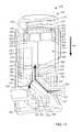
- FIG. 2is a front view of a bodily-fluid transfer device according to an embodiment.
- FIG. 3is a perspective view of the bodily-fluid transfer device of FIG. 2 .
- FIG. 4is an exploded view of the bodily-fluid transfer device of FIG. 2 .
- FIG. 5is a perspective view of a housing included in the bodily-fluid transfer device illustrated in FIG. 2 .
- FIG. 6is a cross-sectional view of the housing illustrated in FIG. 5 taken along the line X 2 -X 2 .
- FIG. 7is a perspective view of a diverter included in the bodily-fluid transfer device of FIG. 2 .
- FIG. 8is a cross-sectional view of the diverter illustrated in FIG. 8 taken along the line X 3 -X 3 .
- FIG. 9is a perspective view of a flow control mechanism included in the bodily-fluid transfer device of FIG. 2 .
- FIG. 10is an exploded view of an actuator mechanism included in the bodily-fluid transfer device of FIG. 2 .
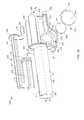
- FIG. 11is a cross-sectional view of the bodily-fluid transfer device of FIG. 2 taken along the line X 1 -X 1 , in a first configuration.
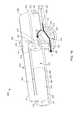
- FIG. 12is a cross-sectional view of the bodily-fluid transfer device of FIG. 2 taken along the line X 1 -X 1 , in a second configuration.
- FIG. 13is a front view of a bodily-fluid transfer device according to an embodiment.
- FIG. 14is a perspective view of the bodily-fluid transfer device of FIG. 13 .
- FIG. 15is an exploded view of the bodily-fluid transfer device of FIG. 13 .
- FIG. 16is a cross-sectional view of a housing included in the bodily-fluid transfer device of FIG. 13 taken along the line X 5 -X 5 in FIG. 14 .
- FIG. 17is a cross-sectional view of the bodily-fluid transfer device taken along the line X 4 -X 4 in FIG. 14 , in a first configuration.
- FIG. 18is a perspective view of the bodily-fluid transfer device of FIG. 13 , in a second configuration.
- FIG. 19is a cross-sectional view of the bodily-fluid transfer device of FIG. 18 taken along the line X 6 -X 6 .
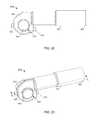
- FIG. 20is a front view of a bodily-fluid transfer device according to an embodiment.
- FIG. 21is a perspective view of the bodily-fluid transfer device of FIG. 20 .
- FIG. 22is an exploded view of the bodily-fluid transfer device of FIG. 20 .
- FIG. 23is a cross-sectional view of a housing included in the bodily-fluid transfer device of FIG. 20 taken along the line X 8 -X 8 in FIG. 21 .
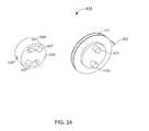
- FIG. 24is a perspective view of a first control member and a second control member included in a flow control mechanism of the bodily-fluid transfer device of FIG. 20 .
- FIG. 25is a cross-sectional view of the bodily-fluid transfer device of FIG. 20 taken along the line X 7 -X 7 in FIG. 21 , in a first configuration.
- FIG. 26is a perspective view of the bodily-fluid transfer device of FIG. 20 , in a second configuration.
- FIG. 27is a cross-sectional view of the bodily-fluid transfer device of FIG. 25 taken along the line X 9 -X 9 .
- FIGS. 28 and 29schematic illustrations of a bodily-fluid transfer device according to an embodiment, in a first and second configuration, respectively.
- a device for procuring bodily-fluid samples from a patientincludes a housing, a fluid reservoir, a flow control mechanism, and an actuator.
- the housingincludes a proximal end portion and a distal end portion and defines an inner volume therebetween.
- the housinghas an inlet port that is configured to be fluidically coupled to a patient and an outlet port that is configured to be fluidically coupled to a sample reservoir.
- the fluid reservoiris disposed within the inner volume of the housing and is configured to receive and isolate a first volume of a bodily-fluid withdrawn from the patient.
- the flow control mechanismdefines a first lumen and a second lumen and is disposed in the housing for rotational movement from a first configuration, in which the inlet port is placed in fluid communication with the fluid reservoir such that the bodily-fluid can flow from the inlet port, through the first lumen, and to the fluid reservoir, to a second configuration, in which the inlet port is placed in fluid communication with the outlet port such that the bodily-fluid can flow from the inlet, through the second lumen and to the outlet port.
- the actuatoris configured to create a negative pressure in the fluid reservoir when actuated by a user.
- the actuatoris operably coupled to the flow control mechanism and is configured to rotate the flow control mechanism from the first configuration to the second configuration after the first volume of bodily-fluid is received in the fluid reservoir from the patient.
- a device for procuring bodily-fluid samples from a patientincludes a housing, an actuator, a diverter, and a flow control mechanism.
- the housinghas a proximal end portion and a distal end portion and defines an inner volume therebetween.
- the actuatoris movably disposed in the housing.
- the actuatorincludes a sealing member and a fluid reservoir defined, at least in part, by the sealing member.
- the actuatoris configured to create a negative pressure in the fluid reservoir when actuated by a user.
- the diverteris disposed in the housing and has an inlet port that is configured to be fluidically coupled to the patient, a first outlet port that is configured to be fluidically coupled to the fluid reservoir, and a second outlet port that is configured to be fluidically coupled to a sample reservoir.
- the flow control mechanismdefines a first lumen and a second lumen.
- the flow control mechanismis disposed in the diverter and is rotatable from a first configuration, in which the inlet port is placed in fluid communication with the first outlet port such that bodily-fluid can flow from the inlet port, through the first lumen and to the first outlet port, to a second configuration, in which the inlet port is placed in fluid communication with the second outlet port such that the bodily-fluid can flow from the inlet, through the second lumen and to the second outlet port.
- a device for procuring bodily-fluid samples from a patientincludes a housing, a flow control mechanism, and an actuator.
- the housinghas a proximal end portion and a distal end portion and defines an inner volume therebetween.
- the housinghas an inlet port configured to be fluidically coupled to the patient and an outlet port configured to be fluidically coupled to a sample reservoir.
- the flow control mechanismdefines a first lumen and a second lumen.
- the flow control mechanismis disposed in the housing and is rotatable between a first configuration, in which the inlet port is placed in fluid communication with a fluid reservoir defined, at least in part, by the housing such that bodily-fluid can flow from the inlet port, through the first lumen and to the fluid reservoir, to a second configuration, in which the inlet port is placed in fluid communication with the outlet port such that the bodily-fluid can flow from the inlet, through the second lumen and to the outlet port.
- the actuatoris movably disposed in the housing and is operably coupled to the flow control mechanism.
- the actuatoris configured to create a negative pressure in the fluid reservoir when actuated by the user.
- the actuatoris further configured to rotate the flow control mechanism from the first configuration to the second configuration after a first volume of bodily-fluid is received in the fluid reservoir from the patient.
- a device for procuring bodily-fluid samples from a patientincludes a housing, a seal member, a fluid reservoir, a flow control mechanism, and an actuator.
- the housinghas a proximal end portion and a distal end portion and defines an inner volume therebetween.
- the housinghas an inlet port configured to be fluidically coupled to the patient.
- the seal memberis movably disposed in the inner volume and is configured to define, at least partially, the fluid reservoir disposed in the inner volume.
- the fluid reservoiris configured to receive and isolate a first volume of bodily-fluid withdrawn from the patient.
- the flow control mechanismis movably disposed in the housing and is configured to move between a first configuration, in which the bodily-fluid can flow from the inlet port, through the flow control mechanism and to the fluid reservoir, to a second configuration, in which the fluid reservoir is fluidically isolated from the inlet port.
- the actuatoris operably coupled to the seal member and the flow control mechanism.
- the actuatorincludes a spring configured to move the seal member from a first position to a second position to create a negative pressure in the fluid reservoir.
- the actuatoris configured to move the flow control mechanism from the first configuration to the second configuration after a first volume of bodily-fluid is received in the fluid reservoir from the patient.
- a device for procuring bodily-fluid samples from a patientincludes a housing, a flow control mechanism, and an actuator.
- the housinghas a proximal end portion and a distal end portion and defines an inner volume therebetween.
- the housinghas an inlet port configured to be fluidically coupled to the patient and an outlet port configured to be fluidically coupled to a sample reservoir.
- the flow control mechanismis disposed in the housing and includes a first control member and a second control member.
- the second control memberdefines a first lumen and a second lumen and is rotatably movable between a first configuration, in which the inlet port is placed in fluid communication with a fluid reservoir defined, at least in part, by the housing such that bodily-fluid can flow from the inlet port, through the first lumen and to the fluid reservoir, to a second configuration, in which the inlet port is placed in fluid communication with the outlet port such that the bodily-fluid can flow from the inlet, through the second lumen and to the outlet port.
- the actuatoris movably disposed in the housing and is operably coupled to the flow control mechanism.
- the actuatoris configured to create a negative pressure in the fluid reservoir when actuated by the user.
- the actuatoris further configured to rotate the second control member from the first configuration to the second configuration after a first volume of bodily-fluid is received in the fluid reservoir from the patient.
- a device for procuring bodily-fluid samples from a patientincludes a diverter, a flow control mechanism, and an actuator mechanism.
- the diverterdefines an inlet port, a first outlet port, and a second outlet port.
- the first outlet portis fluidically coupled to a first fluid reservoir and the second outlet port is fluidically coupled to a second reservoir, fluidically isolated from the first fluid reservoir.
- the flow control mechanismis configured to be disposed, at least partially within the diverter.
- the actuator mechanismis configured to engage the flow control mechanism to move the flow control mechanism between a first configuration, in which a flow of bodily-fluid can enter the first fluid reservoir, and a second configuration, in which a flow of bodily-fluid can enter the second fluid reservoir.
- a bodily-fluid transfer devicecan be configured to selectively divert a first, predetermined amount of a flow of a bodily-fluid to a first reservoir before permitting the flow of a second amount of the bodily-fluid into a second reservoir.
- the second amount of bodily-fluidcan be used for diagnostic or other testing, while the first amount of bodily-fluid, which may contain microbes from a bodily surface, is isolated from the bodily-fluid to be tested.
- the first amount of bodily-fluidcan be subsequently used for different types of testing (e.g., CBC, other blood chemistry tests) or can be simply sequestered.
- a bodily-fluid transfer deviceis configured to automatically move from a first configuration to a second configuration, for example, without requiring an input or other action by a health care practitioner.
- the bodily-fluid transfer deviceprevents bodily-fluid from flowing or otherwise being introduced into a second reservoir before at least a first amount of bodily-fluid (e.g., a predetermined amount) is first introduced into a first reservoir.
- “bodily-fluid”can include any fluid obtained from a body of a patient, including, but not limited to, blood, cerebrospinal fluid, urine, bile, lymph, saliva, synovial fluid, serous fluid, pleural fluid, amniotic fluid, and the like, or any combination thereof.
- the term “set”can refer to multiple features or a singular feature with multiple parts.
- the set of wallscan be considered as one wall with distinct portions, or the set of walls can be considered as multiple walls.
- a monolithically constructed itemcan include a set of walls.
- Such a set of wallscan include, for example, multiple portions that are in discontinuous from each other.
- a set of wallscan also be fabricated from multiple items that are produced separately and are later joined together (e.g., via a weld, an adhesive or any suitable method).
- proximal and distalrefer to the direction closer to and away from, respectively, a user who would place the device into contact with a patient.
- distal endthe end of a device first touching the body of the patient
- opposite end of the devicee.g., the end of the device being manipulated by the user
- an engagement surfaceis intended to mean a single surface or multiple surfaces unless explicitly expressed otherwise.
- FIG. 1is a schematic illustration of a portion of a bodily-fluid transfer device 100 , according to an embodiment.
- the bodily-fluid transfer device 100(also referred to herein as “fluid transfer device” or “transfer device”) is configured to permit the withdrawal of bodily-fluid from a patient such that a first portion or amount of the withdrawn fluid is diverted away from a second portion or amount of the withdrawn fluid that is to be used as a biological sample, such as for testing for the purpose of medical diagnosis and/or treatment.
- the transfer device 100is configured to transfer a first, predetermined amount of a bodily-fluid to a first collection reservoir and a second amount of bodily-fluid to one or more bodily-fluid collection reservoirs fluidically isolated from the first collection reservoir, as described in more detail herein.
- the transfer device 100includes a diverter 120 , a first reservoir 170 , and a second reservoir 180 , different from the first reservoir 170 .
- the diverter 120includes an inlet port 122 and two or more outlet ports, such as a first outlet port 124 and a second outlet port 126 shown in FIG. 1 .
- the inlet port 122is configured to be fluidically coupled to a medical device defining a pathway P for withdrawing and/or conveying the bodily-fluid from the patient to the transfer device 100 .
- the inlet port 122can be fluidically coupled to a needle or other lumen-containing device (e.g., flexible sterile tubing). In this manner, the diverter 120 can receive the bodily-fluid from the patient via the needle or other lumen-containing device.
- the first outlet port 124 of the diverter 120is configured to be fluidically coupled to the first reservoir 170 .
- the first reservoir 170is monolithically formed with the first outlet port 124 and/or a portion of the diverter 120 .
- the first reservoir 170can be mechanically and fluidically coupled to the diverter 120 via an adhesive, a resistance fit, a mechanical fastener, any number of mating recesses, a threaded coupling, and/or any other suitable coupling or combination thereof.
- the first reservoir 170can be physically (e.g., mechanically) coupled to the diverter 120 such that an interior volume defined by the first reservoir 170 is in fluid communication with the first outlet port 120 of the diverter 120 .
- the first reservoir 170can be operably coupled to the first outlet port 124 of the diverter 120 via an intervening structure (not shown in FIG. 1 ), such as a flexible sterile tubing. More particularly, the intervening structure can define a lumen configured to place the first reservoir 170 in fluid communication with the first outlet port 124 .
- the first reservoir 170is configured to receive and contain the first, predetermined amount of the bodily-fluid. In some embodiments, the first reservoir 170 is configured to contain the first amount of the bodily-fluid such that the first amount is fluidically isolated from a second amount of the bodily-fluid (different from the first amount of bodily-fluid) that is subsequently withdrawn from the patient.
- the first reservoir 170can be any suitable reservoir for containing a bodily-fluid, such as a pre-sample reservoir described in detail in U.S. Pat. No. 8,197,420 (“the '420 patent”), the disclosure of which is incorporated herein by reference in its entirety.
- first, predetermined amountand “first amount” describe an amount of bodily-fluid configured to be received or contained by the first reservoir 170 . Furthermore, while the term “first amount” does not explicitly describe a predetermined amount, it should be understood that the first amount is the first, predetermined amount unless explicitly described differently.
- the second outlet port 126 of the diverter 120is configured to be fluidically coupled to the second reservoir 180 .
- the second reservoir 180is monolithically formed with the second outlet port 126 and/or a portion of the diverter 120 .
- the second reservoir 180can be mechanically coupled to the second outlet port 126 of the diverter 120 or operably coupled to the second outlet port 126 via an intervening structure (not shown in FIG. 1 ), such as described above with reference to the first reservoir 170 .
- the second reservoir 180is configured to receive and contain the second amount of the bodily-fluid.
- the second amount of bodily-fluidcan be an amount withdrawn from the patient subsequent to withdrawal of the first amount.
- the second reservoir 180is configured to contain the second amount of the bodily-fluid such that the second amount is fluidically isolated from the first amount of the bodily-fluid.
- the second reservoir 170can be any suitable reservoir for containing a bodily-fluid, including, for example, a sample reservoir as described in the '420 patent incorporated by reference above.
- the term “second amount”describes an amount of bodily-fluid configured to be received or contained by the second reservoir 180 .
- the second amountcan be any suitable amount of bodily-fluid and need not be predetermined.
- the second amount received and contained by the second reservoir 180is a second predetermined amount.
- the first reservoir 170 and the second reservoir 180can be coupled to (or formed with) the diverter 120 in a similar manner. In other embodiments, the first reservoir 170 and the second reservoir need not be similarly coupled to the diverter 120 .
- the first reservoir 170can be monolithically formed with the diverter 120 (e.g., the first outlet port 124 ) and the second reservoir 180 can be operably coupled to the diverter 120 (e.g., the second outlet port 126 ) via an intervening structure, such as a flexible sterile tubing.
- the transfer device 100further includes an actuator 140 and a flow control mechanism 130 defining a first channel 138 and a second channel 139 .
- the actuator 140can be included in or otherwise operably coupled to the diverter 120 .
- the actuator 140can be configured to control a movement of the flow control mechanism 130 (e.g., between a first configuration and a second configuration).
- the actuator 140can be movable between a first position corresponding to the first configuration of the flow control mechanism 130 , and a second position, different from the first position, corresponding to the second configuration of the flow control mechanism 130 .
- the actuator 140is configured for uni-directional movement.
- the actuator 140can be moved from its first position to its second position, but cannot be moved from its second position to its first position. In this manner, the flow control mechanism 130 is prevented from being moved to its second configuration before its first configuration, thus requiring that the first amount of the bodily-fluid be directed to the first reservoir 170 and not the second reservoir 180 .
- the flow control mechanism 130is configured such that when in the first configuration, the first channel 138 fluidically couples the inlet port 122 to the first outlet port 124 and when in the second configuration, the second channel 139 fluidically couples the inlet portion 122 to the second outlet port 126 .
- the actuator 140is coupled to the flow control mechanism 130 and is configured to move the flow control mechanism 130 in a translational motion between the first configuration and the second configuration.
- the flow control mechanism 130can be in the first configuration when the flow control mechanism 130 is in a distal position relative to the transfer device 100 .
- the actuator 140can be actuated to move the flow control device 130 in the proximal direction to a proximal position relative to the transfer device 100 , thereby placing the flow control mechanism 130 in the second configuration. In other embodiments, the actuator 140 can be actuated to move the flow control mechanism 130 in a rotational motion between the first configuration and the second configuration.
- the second outlet port 126is fluidically isolated from the inlet port 122 .
- the first outlet port 124is fluidically isolated from the inlet port 122 .
- the flow control mechanism 130can direct, or divert the first amount of the bodily-fluid to the first reservoir 170 via the first outlet port 124 when the flow control mechanism 130 is in the first configuration and can direct, or divert the second amount of the bodily-fluid to the second reservoir 180 via the second outlet port 126 when the flow control mechanism 130 is in the second configuration.
- the actuator 140can be operably coupled to the first reservoir 170 .
- the actuator 140(or at least the portion of the actuator 140 ) can be configured to cause a vacuum within the first reservoir 170 , thereby initiating flow of the bodily-fluid through the transfer device 100 and into the first reservoir 170 when the diverter 120 is in its first configuration.
- the actuator 140can include any suitable mechanism for actuating the transfer device 100 (e.g., at least the flow control mechanism 130 ), such as, for example, a rotating disc, a plunger, a slide, a dial, a button, and/or any other suitable mechanism or combination thereof. Examples of suitable actuators are described in more detail herein with reference to specific embodiments.
- the diverter 120is configured such that the first amount of bodily-fluid need be conveyed to the first reservoir 170 before the diverter 120 will permit the flow of the second amount of bodily-fluid to be conveyed through the diverter 120 to the second reservoir 180 .
- the diverter 120can be characterized as requiring compliance by a health care practitioner regarding the collection of the first, predetermined amount (e.g., a pre-sample) prior to a collection of the second amount (e.g., a sample) of bodily-fluid.
- the diverter 120can be configured to prevent a health care practitioner from collecting the second amount, or the sample, of bodily-fluid into the second reservoir 180 without first diverting the first amount, or pre-sample, of bodily-fluid to the first reservoir 170 .
- the health care practitioneris prevented from including (whether intentionally or unintentionally) the first amount of bodily-fluid, which is more likely to contain bodily surface microbes and/or other undesirable external contaminants that are not representative of the in vivo conditions of a patient's bodily-fluid system, in the bodily-fluid sample to be used for analysis.
- the forced-compliance aspect of the diverter 120is described in more detail herein with reference to specific embodiments.
- the diverter 120is configured to automatically (i.e., without requiring an input or other action by a health care practitioner or other operator of the transfer device 100 ) fluidically isolate the inlet port 122 from the first outlet port 124 .
- the diverter 120can be configured such that the flow control mechanism 130 will automatically fluidically isolate the first outlet port 124 from the inlet port 122 when the first reservoir 170 has received the first, predetermined amount of bodily-fluid. As such, additional flow of bodily-fluid in excess of the first amount into the first reservoir 170 is prevented.
- the diverter 120is configured such that the flow control mechanism 130 automatically moves from its first configuration to its second configuration after the first amount of bodily-fluid is conveyed to the first reservoir 170 .
- the actuator 140can have a third position, different from the first and second positions, which corresponds to a third configuration of the flow control mechanism 130 .
- the flow control mechanism 130can fluidically isolate the inlet port 122 from both the first outlet port 124 and the second outlet port 126 simultaneously. Therefore, when the flow control mechanism 130 is in its third configuration, flow of bodily-fluid from the inlet port 122 to either the first reservoir 170 or the second reservoir 180 is prevented.
- the actuator 140can be actuated to place the flow control mechanism 130 in the first configuration such that a bodily-fluid can flow from the inlet port 122 to the first reservoir 170 , then moved to the second configuration such that the bodily-fluid can flow from the inlet port 122 to the second reservoir 180 , then moved to the third configuration to stop the flow of bodily-fluid into and/or through the diverter 120 .
- the flow control mechanism 130can be moved to the third configuration between the first configuration and the second configuration.
- the flow control mechanism 130can be in the third configuration before being moved to either of the first configuration or the second configuration.
- one or more portions of the transfer device 100are disposed within a housing (not shown in FIG. 1 ).
- a housingnot shown in FIG. 1 .
- at least a portion of one or more of the diverter 120 , the first reservoir 170 , and the actuator 140can be disposed within the housing. In such an embodiment, at least a portion of the actuator 140 is accessible through the housing. Examples of suitable housings are described in more detail herein with reference to specific embodiments.
- a transfer device 200includes a housing 201 , a diverter 220 , a flow control mechanism 230 , and an actuator 240 .
- the transfer device 200can be any suitable shape, size, or configuration.
- the transfer device 200can be square, rectangular, polygonal, and/or any other non-cylindrical shape.
- the housing 201includes a proximal end portion 202 and a distal end portion 203 .
- the distal end portion 203includes a base 206 from which a set of walls 204 extend. More specifically, the walls 204 of the housing 201 define a substantially annular shape and define an inner volume 211 therebetween.
- the proximal end portion 202 of the housing 201is configured to be open such that the inner volume 211 can receive at least a portion of the diverter 220 , a portion of the flow control mechanism 230 , and a portion of the actuator 240 ( FIG. 4 ).
- the housing 201is configured to house at least the portion of the diverter 220 , the portion of the flow control mechanism 230 , and the portion of the actuator 240
- the walls 204 of the housing 201define a set of status windows 210 and a set of channels 205 .
- the status windows 210can be any suitable shape or size and are configured to allow a user to visually inspect at least a portion of the transfer device 200 . While shown in FIG. 5 as including two status windows 210 , in other embodiments, the housing 201 can define any number of status windows 210 , such as, for example, one, three, four, or more.
- the channels 205 defined by the housing 201are configured to extend from the distal end portion 203 and through the proximal end portion 202 . Similarly stated, the channels 205 extend through a proximal surface of the housing 201 . Said yet another way, the channels 205 are open ended at the proximal end portion 202 of the housing 201 .
- the housing 201further includes a set of guide posts 207 and a set of flow control protrusions 208 . While shown in FIGS. 5 and 6 as cylindrical protrusions, the guide posts 207 can be any suitable shape or size and are configured to extend from the base 206 in the proximal direction. In this manner, the guide posts 207 are configured to engage a portion of the diverter 220 and a portion of the actuator 240 , as further described herein.
- the flow control protrusions 208extend from the base 206 in the proximal direction and define notches 209 .
- the flow control protrusions 208are configured to selectively engage the flow control mechanism 230 to move the flow control mechanism 230 between a first configuration and a second configuration, as described in further detail herein. While only one flow control protrusion 208 is shown in FIGS. 5 and 6 , the housing 201 is configured to include two flow control protrusions 208 . In other embodiments, the housing 201 can include any number flow control protrusions 208 such as for example, one, three, four, or more.
- the diverter 220includes a proximal end portion 228 and a distal end portion 229 and defines an inner volume 221 .
- the inner volume 221is configured to receive at least a portion of the flow control mechanism 230 , as further described herein.
- the proximal end portion 228 of the diverter 220includes a first outlet port 224 and can engage a portion of the actuator 240 .
- the distal end portion 229includes an inlet port 222 and a second outlet port 226 . As shown in FIGS.
- the diverter 220is disposed within the inner volume 211 of the housing 201 such that a portion of the inlet port 222 extends through a first channel 205 defined by the walls 204 of the housing 201 and a portion of the second outlet port 226 extends through a second channel 205 opposite the first channel. While not explicitly shown in FIGS. 2-12 , the distal end portion 229 of the diverter 220 is configured to engage the guide posts 207 such that lateral movement of the diverter 220 is limited.
- the distal end portion 229 of the diverter 220can engage the guide posts 207 of the housing 201 such that the diverter 220 is substantially limited to movement in the proximal or distal direction, relative to the housing 201 , as further described herein.
- the inlet port 222 included in the distal end portion 229 of the diverter 220defines an inlet lumen 223 .
- the inlet lumen 223is configured to be in fluid communication with the inner volume 221 .
- the inlet lumen 223 of the inlet port 222extends through a wall defining the inner volume 221 of the diverter 220 .
- the inlet port 222is further configured to be fluidically coupled to a medical device (not shown) defining a fluid flow pathway for withdrawing and/or conveying the bodily-fluid from a patient to the transfer device 200 .
- the inlet port 222can be fluidically coupled to a needle or other lumen-containing device (e.g., flexible sterile tubing).
- a needle or other lumen-containing devicee.g., flexible sterile tubing
- the inlet lumen 223 defined by the inlet port 222is placed in fluid communication with a lumen defined by a lumen-containing device, when the lumen-containing device is coupled to the inlet port 222 .
- the lumen-containing deviceis disposed within a portion of a body of the patient (e.g., within a vein of the patient)
- the inner volume 221 of the diverter 220is placed in fluid communication with the portion of the body of the patient.
- the first outlet port 224 included in the proximal end portion 228 of the diverter 220defines a first outlet lumen 225 .
- the first outlet lumen 225is configured to be in fluid communication with the inner volume 221 of the diverter 220 (e.g., the first outlet lumen 225 extends through the wall defining the inner volume 221 ).
- the second outlet port 226 included in the distal end portion 229 of the diverter 220defines a second outlet lumen 227 in fluid communication with the inner volume 221 .
- the flow control mechanism 230includes a first control member 231 and a second control member 235 . At least a portion of the flow control mechanism 230 is configured to be disposed within the inner volume 221 defined by the diverter 220 . In this manner, the flow control mechanism 230 defines a circular cross-sectional shape such that when the flow control mechanism 230 is disposed within the inner volume 221 , a portion of the flow control mechanism 230 forms a friction fit with the walls of the diverter 220 defining the inner volume 221 , as described in further detail herein.
- the first control member 231includes a set of activation protrusions 232 and a set of cross members 234 (only one of each is shown in FIG. 9 ).
- the activation protrusions 232are configured to engage the flow control protrusion 208 of the housing 201 . More specifically, the activation protrusions 232 can be disposed within the notch 209 defined by the flow control protrusion 208 . Therefore, in use, the flow control protrusions 208 can engage the activation protrusions 232 to move the flow control mechanism 230 between a first configuration and a second configuration.
- the second control member 235defines a first lumen 238 , a second lumen 239 , and a set of channels 237 and is configured to be disposed, at least partially, within the first control member 231 . More particularly, the first control member 231 has a first diameter D 1 and the second control member 235 has a second diameter D 2 larger than the first diameter D 1 . Therefore, when the second control member 235 is disposed within the first control member 231 a portion of the second control member 235 extends beyond a surface of the first control member 231 that defines the first diameter D 1 .
- the channels 237 defined by the second control member 235receive the cross members 234 of the first control member 231 .
- the arrangement of the cross members 234 disposed within the channels 237is such that the second control member 235 is maintained in a desired position relative to the first control member 231 .
- the second control member 235is configured to move concurrently with the first control member 231 when the flow control protrusions 208 engage the activation protrusions 232 of the first control member 231 .
- the flow control mechanism 230is moved between the first configuration and the second configuration when the first control member 231 and the second control member 235 are moved between the first configuration and the second configuration, respectively.
- the first lumen 238is placed in fluid communication with the inlet lumen 223 defined by the inlet port 222 and the first outlet lumen 225 defined by the first outlet port 224 .
- the second lumen 239is placed in fluid communication with the inlet lumen 223 defined by the inlet port 222 and the second outlet lumen 227 defined by the second outlet port 226 , as described in further detail herein.
- the actuator mechanism 240includes an actuator housing 262 , a plunger 248 , a cap 255 , and a spring 261 .
- the actuator mechanism 240is configured to move between a first configuration and a second configuration, thereby moving the transfer device 200 between a first configuration and a second configuration, as described in further detail herein.
- the actuator housing 262includes a proximal end portion 263 and a distal end portion 264 and defines an inner volume 265 .
- the actuator housing 262can be any suitable shape, size or configuration.
- the actuator housing 262can be substantially cylindrical and be configured to be disposed, at least partially, within the housing 201 .
- the inner volume 265is configured to receive the plunger 248 , the spring 261 , and at least a portion of the cap 255 .
- the plunger 248includes a proximal end portion 249 and a distal end portion 249 and a side wall 251 .
- the distal end portion 250is configured to receive the guide posts 207 of the housing 201 , as described in further detail herein.
- the proximal end portion 249includes a set of retention tabs 253 and can receive a portion of the spring 261 . More particularly, the retention tabs 253 included in the proximal end portion 249 of the plunger 248 are configured to engage the spring 261 to removably couple the spring 261 to the plunger 248 .
- the side wall 251 of the plunger 248define a set of notches 252 configured to receive a set of seal members 254 .
- the seal members 254can be any suitable seal members 254 such as for example, o-rings formed from any suitable elastomeric material.
- the plunger 248is disposed within the inner volume 265 of the actuator housing 262 such that the seal members 254 define a friction fit with the inner walls (not shown in FIG. 10 ) that define the inner volume 265 of the actuator housing 262 .
- the seal members 254define a fluidic seal with the inner walls of the actuator housing 262 .
- the plunger 248is disposed within the inner volume 265 such that the plunger 248 divides the inner volume 265 into a first portion 267 that is fluidically isolated from a second portion 270 (see e.g., FIGS. 11 and 12 ).
- the first portion 267 of the inner volume 265is defined between a surface of the proximal end portion 263 of the actuator housing 262 and the proximal end portion 249 of the plunger 248 .
- the first portion 267 of the inner volume 265is configured contain the spring 261 such that the spring 261 is in contact with the surface of the proximal end portion 263 of the actuator housing 262 and the proximal end portion 249 of the plunger 248 .
- the cap 255can be any suitable shape or size and is configured to be disposed, at least partially, within the inner volume 265 of the actuator housing 262 . Furthermore, the cap 255 can be formed from any suitable material. For example, in some embodiments, the cap 255 is formed from an elastomeric material such as silicone. In other embodiments, the cap 255 can be formed from any polymeric material such as, for example, rubber, vinyl, neoprene, or the like.
- the cap 255includes a proximal end portion 256 and a distal end portion 257 .
- the proximal end portion 256is disposed within the inner volume 265 of the actuator housing 262 such that the distal end portion 250 of the plunger 248 and the proximal end portion 256 of the cap defines the second portion 270 of the inner volume (referred to henceforth as “first reservoir”) of the inner volume 265 .
- first reservoirthe proximal end portion 256 of the cap 255 is configured to define a friction fit with the inner walls (not shown in FIG. 10 ) that define the inner volume 265 .
- the proximal end portion 254defines a fluidic seal with the inner walls of the actuator housing 262 .
- the fluidic seal defined by the actuator housing 262 and the plunger 248 and the fluidic seal defined by the actuator housing 262 and the proximal end portion 256 of the cap 255fluidically isolate the fluid reservoir 270 from a portion outside of the fluid reservoir 270 (i.e., the second portion of the inner volume 265 ).
- the distal end portion 257 of the cap 255includes a set of notches 260 configured to receive a set of protrusions 266 of the actuator housing 262 when the proximal end portion 256 is disposed within the inner volume 265 .
- the arrangement of the notches 260 defined by the cap 255 and the protrusions 266 of the actuator housing 262is such that the protrusions 266 form a friction fit with the walls defining the notches 260 . In this manner, the protrusions 266 engage the walls defining the notches 260 to maintain the cap 255 in a desired position relative to the actuator housing 262 when the proximal end portion 256 is disposed within the inner volume 265 .
- the actuator mechanism 240 and the diverter 220are disposed within the housing 201 such that the distal end portion 257 of the cap 255 is in contact with the proximal end portion 228 of the diverter 220 , as described in further detail herein.
- the cap 255further defines an inlet port 258 and a set of guide post ports 259 .
- the inlet port 258is configured to receive a portion of the first outlet port 224 included in the diverter 220 . More specifically, the inlet port 258 receives the first outlet port 224 such that the inlet port 258 form a fluidic seal with an outer surface of the first outlet port 224 .
- the guide post ports 259receive a portion of the guide posts 207 of the housing 201 such that the guide post ports 259 form a fluidic seal with an outer surface of the guide posts 207 . In this manner, a portion of the guide posts 207 and a portion of the first outlet port 224 are disposed within the fluid reservoir 270 defined by the actuator housing 262 .
- the fluid reservoir 270(i.e., the second portion of the inner volume 265 ) is in fluid communication with the first outlet lumen 225 , as described in further detail herein.
- the transfer device 200can be stored in a storage configuration in which the second control member 235 of the flow control mechanism 230 fluidically isolates the inlet port 222 , the first outlet port 224 , and the second outlet port 226 from the inner volume 221 defined by the diverter 220 .
- first lumen 238 and the second lumen 239are fluidically isolated from the inlet lumen 223 , the first outlet lumen 225 , and the second outlet lumen 227 .
- the friction fit defined by the second control member 235 and the walls of the diverter 220 defining the inner volume 221maintain the flow control mechanism 230 in the storage configuration until the flow control mechanism 230 is moved from the storage configuration.
- a usercan engage the transfer device 200 to couple the inlet port 222 to a proximal end portion of a lumen-defining device (not shown) such as, for example, a butterfly needle or, as an additional example, surgical tubing coupleable with a Luer-Lok-type connection that allows for mating to an indwelling catheter or hub or other general vascular access device(s)/product(s).
- a lumen-defining devicesuch as, for example, a butterfly needle or, as an additional example, surgical tubing coupleable with a Luer-Lok-type connection that allows for mating to an indwelling catheter or hub or other general vascular access device(s)/product(s).
- the distal end portion of the lumen-defining devicecan be disposed within a portion of the body of a patient (e.g., a vein), thus, the inlet lumen 223 is in fluid communication with the portion of the body of the patient.
- the second outlet port 226can be coupled to an external fluid reservoir (not shown).
- the external fluid reservoircan be any suitable reservoir.
- the external fluid reservoircan be a BacT/ALERT® SN or a BacT/ALERT® FA, manufactured by BIOMERIEUX, INC.
- a usercan place the transfer device 200 in the first configuration by applying an activation force to the actuator mechanism 240 , thereby moving at least a portion of the actuator mechanism 240 , the diverter 220 , and the flow control mechanism 230 in the distal direction towards the first configuration, as shown by the arrow AA in FIG. 11 . More specifically and as described above, the distal end portion 250 of the plunger 248 engages the guide posts 207 of the housing 201 .
- the arrangement of the plunger 248 and the guide posts 207is such that as the user applies the activation force to the actuator mechanism 240 , the position of the plunger 248 , relative to the housing 201 , is maintained. Therefore, the activation force applied by the user moves the actuator housing 262 , the cap 255 , the diverter 220 , and the flow control mechanism 230 in the direction of the arrow AA, but not the plunger 248 .
- the distal movement of the actuator housing 262is such that a portion of the activation force is configured to compress the spring 261 , and as such, the height of the second portion 267 of the inner volume is reduced.
- the compression of the spring 261is such that the spring 261 exerts a reaction force (e.g., a force of expansion) in response to the portion of the activation force compressing the spring 261 .
- a reaction forcee.g., a force of expansion
- the spring 261is configured return to an expanded configuration when the activation force is removed.
- the distal movement of the actuator housing 262 relative to the plunger 248is such that the height of the fluid reservoir 270 is increased.
- the increase in the heighti.e., the increase in volume
- the flow control protrusions 208engage the activation protrusions 232 (not shown in FIG. 11 ) included in the first control member 231 to move the flow control mechanism 230 toward the first configuration, as indicated by the arrow BB.
- the first lumen 238 defined by the second control member 235is placed in fluid communication with the inlet lumen 223 defined by the inlet port 222 and the first outlet lumen 225 defined by the first outlet port 224 .
- the inlet lumen 223 of the inlet port 222 , the first lumen 238 of the second control member 235 , and the first outlet lumen 225 of the first outlet port 224define a fluid flow path such that the fluid reservoir 270 defined by the actuator housing 262 is in fluid communication with the inlet port 222 .
- the fluid reservoir 270 of the actuator housing 262is placed in fluid communication with the portion of the patient (e.g., the vein).
- the negative pressure within the fluid reservoir 270is such that the negative pressure differential introduces a suction force within the portion of the patient. In this manner, a bodily-fluid is drawn into the fluid reservoir 270 of the actuator housing 262 .
- the bodily-fluidcan contain undesirable microbes such as, for example, dermally-residing microbes.
- the magnitude of the suction forcecan be modulated by increasing or decreasing the amount of activation force applied to the actuator mechanism 240 .
- itcan be desirable to limit the amount of suction force (i.e., modulate the negative pressure during a blood draw) introduced to a vein to reduce, minimize, or even eliminate vein collapse and/or one potential source of hemolysis.
- the usercan reduce the amount of force applied to the actuator mechanism 240 . In this manner, the reaction force exerted by the expansion of the spring 261 (e.g., as described above) is sufficient to overcome a portion of the activation force applied by the user.
- the spring 261can expand to move the plunger 248 and the housing 201 in the distal direction, relative to the actuator housing 262 , the cap 255 , the diverter 220 , and the flow control mechanism 230 .
- the distal movement of the plunger 248 and housing 201is such that the flow control protrusions 208 engage the activation protrusions 232 of the flow control mechanism 230 to move the flow control mechanism 230 towards the storage configuration.
- the rotation of the flow control mechanism 230reduces the size of the fluid pathway (e.g., an inner diameter) between the inlet lumen 223 and the first lumen 238 and the first outlet port 225 and the first lumen 238 , thereby reducing the suction force introduced into the vein of the patient.
- the size of the fluid pathwaye.g., an inner diameter
- the transfer device 200can be configured to transfer bodily-fluid until the pressure within the fluid reservoir 270 defined by the actuator housing 262 is in equilibrium with the pressure of the portion of the body in which the lumen-defining device is disposed (e.g., the vein).
- the equalizing of the pressure between the second portion 176 of the inner volume 265 and the portion of the bodystops the flow of the bodily-fluid into the actuator housing 262 .
- the predetermined amount of bodily-fluide.g., volume
- the predetermined amount of bodily-fluidis at least equal to the combined volume of the inlet lumen 223 , the first lumen 238 , the first outlet lumen 225 , and the lumen-defining device.
- the transfer device 200can be moved from the first configuration to the second configuration by further moving the actuator mechanism 240 in the distal direction, as indicated by the arrow DD. Expanding further, the user can apply an activation force to the actuator mechanism 240 such that the actuator housing 262 , the cap 255 , the diverter 220 , and the flow control mechanism 230 move in the distal direction. With the desired amount of the bodily-fluid disposed within the fluid reservoir 270 the volume of the fluid reservoir 270 is configured to remain constant as the actuator housing 262 and the cap 255 move relative to the plunger 248 . Similarly stated, the pressure of the fluid reservoir 270 is configured to remain substantially unchanged as the transfer device 200 is moved from the first configuration to the second configuration.
- the flow control protrusions 208engage the activation protrusions 232 (not shown in FIG. 12 ) included in the first control member 231 to move the flow control mechanism 230 toward the second configuration, as indicated by the arrow EE.
- the second lumen 239 defined by the second control member 235is placed in fluid communication with the inlet lumen 223 defined by the inlet port 222 and the second outlet lumen 227 defined by the second outlet port 226 .
- the inlet lumen 223 of the inlet port 222 , the second lumen 239 of the second control member 235 , and the second outlet lumen 227 of the second outlet port 226define a fluid flow path such that the external reservoir (not shown in FIG. 12 ) is in fluid communication with the inlet port 222 and, therefore, the portion of the patient (e.g., the vein).
- the external reservoiris configured to define a negative pressure (e.g., the known external reservoirs referred to herein are vessels defining a negative pressure).
- the negative pressure within the external reservoiris such that the negative pressure differential between the external reservoir and the portion of the body of the patient introduces a suction force within the portion of the patient.
- a desired amount of bodily-fluidis drawn into the external reservoir and is fluidically isolated from the first, predetermined amount of bodily-fluid contained within the fluid reservoir 270 defined by the actuator housing 262 .
- the bodily-fluid contained in the external reservoiris substantially free from microbes generally found outside of the portion of the patient (e.g., dermally residing microbes, microbes within a lumen defined by the transfer device 200 , microbes within the lumen defined by the lumen defining device, and/or any other undesirable microbe(s)).
- the usercan remove the activation force from the actuator mechanism 240 (e.g., remove the portion of the hand engaging the actuator mechanism 240 ).
- the spring 261exerts the force of expansion (described above) to move the transfer device 200 from the second configuration to the storage configuration.
- the first outlet port 224is fluidically isolated from the first lumen 238 and/or the second lumen 239 of the flow control mechanism 230 .
- the bodily-fluid contained within the actuator housing 262is fluidically isolated from a volume outside the actuator housing 262 and the external reservoir can be decoupled from the transfer device 200 .
- the bodily-fluid contained within the actuator housing 262is isolated from the patient and the healthcare worker, and can be safely disposed of (e.g., in a biohazard materials container) in a “closed” device.
- a transfer devicecan include a diverter and housing that are monolithically formed.
- FIGS. 13-19illustrate a transfer device 300 according to an embodiment.
- FIGS. 13 and 14illustrate the transfer device 300 in a first configuration.
- the transfer device 300includes a housing 301 , having a diverter 320 and defining a fluid reservoir 370 , a flow control mechanism 330 , and an actuator 340 .
- the housing 301includes a proximal end portion 302 and a distal end portion 303 .
- the distal end portion 303 of the housing 301includes a set of walls 304 that define a channel 305 configured to receive a distal portion 342 of the actuator 340 .
- the walls 304can be configured to define the channel 305 with any suitable shape, size, or configuration. For example as shown in FIG. 16 , the walls 304 can be configured to further define a slot 319 in the channel 305 configured to receive an activation extension 346 included in the actuator 340 ( FIG. 15 ).
- the slot 319can be configured to receive the activation extension 346 included in the distal portion 342 of the actuator 340 , disposed within the channel 305 , such that the activation extension 346 can pass through the walls 304 and be disposed substantially outside the channel 305 , as described in further detail herein.
- the walls 304 of the distal end portion 303 of the housing 301also include a recessed surface 315 and a stop 313 ( FIGS. 15 and 16 ).
- the stop 313defines a proximal boundary of the channel 305 that can limit the movement of the actuator 340 within the channel 305 .
- the stop 313defines a passageway 314 configured to receive a portion of the actuator 340 such that the portion of the actuator 340 can extend in the proximal direction beyond the stop 313 , as further described herein.
- the recessed surface 315is configured to be a flat surface from which the diverter 320 can extend.
- the diverter 320is a set of walls configured to extend perpendicularly from the recessed surface 315 .
- the diverter 320receives at least a portion of the flow control mechanism 340 , as described in further detail herein. While shown and described as extending perpendicularly from the recessed surface 315 , in other embodiments, the diverter 320 can extend from the recessed surface 315 at any suitable angular orientation.
- the proximal end portion 302 of the housing 301includes a set of walls 318 that extend from the stop 313 in the proximal direction.
- the walls 318define a tubular shape substantially enclosed at the distal end by the stop 313 and open at the proximal end.
- the walls 318define a slot 312 and an inner volume 311 configured to receive a proximal end portion 341 of the actuator 340 .
- the proximal end portion 302 of the housing 301 , the stop 313 , and the proximal end portion 341 of the actuator 340define a fluid reservoir 370 configured to receive and/or contain a bodily fluid.
- the diverter 320includes an inlet port 322 , a first outlet port 324 , and a second outlet port 326 , and defines an inner volume 321 .
- the inner volume 321is configured to receive at least a portion of the flow control mechanism 330 , as further described herein.
- the inlet port 322 of the diverter 320defines an inlet lumen 323 .
- the inlet lumen 323is configured to be in fluid communication with the inner volume 321 .
- the inlet lumen 323 of the inlet port 322extends through a wall defining the inner volume 321 of the diverter 320 .
- the inlet port 322is further configured to be fluidically coupled to a medical device (not shown) defining a fluid flow pathway for withdrawing and/or conveying the bodily-fluid from a patient to the transfer device 300 .
- the inlet port 322can be fluidically coupled to a needle or other lumen-containing device (e.g., flexible sterile tubing).
- the inlet lumen 323 defined by the inlet port 322is placed in fluid communication with a lumen defined by a lumen-containing device, when the lumen-containing device is coupled to the inlet port 322 .
- the inner volume 321 of the diverter 320is placed in fluid communication with the portion of the body of the patient.
- the first outlet port 324 of the diverter 320defines a first outlet lumen 325 .
- the first outlet lumen 325is configured to be in fluid communication with the inner volume 321 of the diverter 320 and the fluid reservoir 370 (described above).
- the first outlet lumen 325is configured to extend through the wall defining the inner volume 321 and through a portion of the stop 313 defining the fluid reservoir 370 , thereby placing the fluid reservoir 370 in fluid communication with the inner volume 321 .
- the second outlet port 326 of the diverter 320defines a second outlet lumen 327 and can be coupled to an external fluid reservoir. In this manner, the second outlet lumen 327 can extend through the wall defining the inner volume 321 to be in fluid communication with the inner volume 321 and can be fluidically coupled to the external reservoir to place the external fluid reservoir in fluid communication with the inner volume 321 .
- the flow control mechanism 330includes a first control member 331 and a second control member 335 . At least a portion of the flow control mechanism 330 is configured to be disposed within the inner volume 321 defined by the diverter 320 . In this manner, the flow control mechanism 330 defines a circular cross-sectional shape such that when the flow control mechanism 330 is disposed within the inner volume 321 , a portion of the flow control mechanism 330 forms a friction fit with the walls of the diverter 320 defining the inner volume 321 , as described in further detail herein.
- the first control member 331includes a set of activation protrusions 332 configured to engage a set of protrusion 347 included in the activation extension 346 of the actuator 340 . Therefore, in use, the actuator 340 can engage the activation protrusions 332 to move the flow control mechanism 330 between a first configuration and a second configuration.
- the second control member 335defines a first lumen 338 and a second lumen 339 and can be formed from any suitable material.
- the second control member 335is formed from silicone.
- the second control member 335can be any suitable elastomer configured to deform when disposed within the inner volume 321 of the diverter.
- the second control member 335has a diameter larger than the diameter of the inner volume 321 . In the manner, the diameter of the second control member 335 is reduced when the second control member 335 is disposed within the inner volume 321 . Thus, the outer surface of the second control member 335 forms a friction fit with the inner surface of the walls defining the inner volume 321 .
- the second control member 335is configured to be coupled to the first control member 331 .
- the first control member 331can be coupled to the second control member 335 via a mechanical fastener and/or adhesive.
- the first control member 331 and the second control member 335can be coupled in any suitable manner.
- the second control member 335is configured to move concurrently with the first control member 331 when the activation extension 347 of the actuator 340 engages the activation protrusions 332 of the first control member 331 .
- the flow control mechanism 330is moved between the first configuration and the second configuration when the first control member 331 and the second control member 335 are moved between the first configuration and the second configuration, respectively.
- the first lumen 338is placed in fluid communication with the inlet lumen 323 defined by the inlet port 322 and the first outlet lumen 325 defined by the first outlet port 324 .
- the second lumen 339is placed in fluid communication with the inlet lumen 323 defined by the inlet port 322 and the second outlet lumen 327 defined by the second outlet port 326 , as described in further detail herein.
- the actuator mechanism 340includes the proximal end portion 341 , the distal end portion 342 , and an actuator arm 343 therebetween.
- the actuator mechanism 340is configured to move between a first configuration and a second configuration, thereby moving the transfer device 300 between a first configuration and a second configuration, as described in further detail herein.
- the proximal end portion 341includes a plunger 348 configured to be disposed within the inner volume 311 of the housing 301 . More particularly, the plunger 348 includes a seal member 354 configured to define a friction fit with the inner surface of the walls 318 defining the inner volume 311 .
- the seal member 354defines a fluidic seal with the inner surface of the walls 318 defining the inner volume 311 such that a portion of the inner volume 311 proximal of the seal member 354 is fluidically isolated from a portion of the inner volume 311 distal of the seal member 354 .
- the actuator arm 343is configured to extend from the proximal end portion 341 of the actuator 340 through the passageway 314 defined by the stop 313 . Therefore, as described above, the distal end portion 342 of the actuator 340 is disposed on a distal side of the stop 313 . More specifically, the distal end portion 342 includes an engagement portion 344 and the activation portion 346 . The engagement portion 344 and at least a portion (e.g., a distal portion) of the actuator arm 343 are configured to be disposed within the channel 305 such that the activation portion 346 can extend through the slot 319 , as described above. In this manner, a user can engage the engagement portion 344 to move the actuator 340 in a distal direction between a first configuration and a second configuration, as further described herein.
- the transfer device 300can be stored in the first configuration in which the first lumen 338 of the second control member 335 is in fluid communication with the inlet port 322 and the first outlet port 324 .
- the friction fit defined by the second control member 335 and the walls of the diverter 320 defining the inner volume 321maintain the flow control mechanism 330 in the first configuration until the actuator 340 moves the flow control mechanism 330 to the second configuration.
- a usercan engage the transfer device 300 to couple the inlet port 322 to a proximal end portion of a lumen-defining device (not shown) such as, for example, a butterfly needle.
- a lumen-defining devicesuch as, for example, a butterfly needle.
- the inlet port 322coupled to the lumen-defining device the inlet lumen 323 is placed in fluid communication with the lumen defined by the lumen-defining device.
- the distal end portion of the lumen-defining devicecan be disposed within a portion of the body of a patient (e.g., a vein), thus, the inlet lumen 323 is in fluid communication with the portion of the body of the patient.
- the second outlet port 326can be coupled to an external fluid reservoir (not shown).
- the external fluid reservoircan be any suitable reservoir.
- the external fluid reservoircan be a BacT/ALERT® SN or a BacT/ALERT® FA blood culture collection bottle with media specifically designed to facilitate the growth of certain types of microbes (e.g., aerobic media/broth and/or aerobic media/broth), manufactured by BIOMERIEUX, INC.
- BacT/ALERT® SNor a BacT/ALERT® FA blood culture collection bottle with media specifically designed to facilitate the growth of certain types of microbes (e.g., aerobic media/broth and/or aerobic media/broth), manufactured by BIOMERIEUX, INC.
- a usercan begin the transfer of a bodily-fluid by applying an activation force to the engagement portion 344 of the actuator 340 , thereby moving the actuator 340 the distal direction, as shown by the arrow GG in FIG. 17 .
- the plunger 348engages the inner surface of the walls 318 defining the inner volume 311 such that the volume of the fluid reservoir 370 is increased (e.g., as defined by the plunger 348 , the walls 318 of the housing 301 and the stop 313 ).
- the increase in the volume of the fluid reservoir 370produces a negative pressure within the fluid reservoir 370 .
- negative pressure differentialintroduces a suction force within the first lumen 338 , the inlet lumen 323 , and the first outlet lumen 325 .
- the inlet lumen 323 of the inlet port 322 , the first lumen 338 of the second control member 335 , and the first outlet lumen 325 of the first outlet port 324define a fluid flow path such that the second portion 376 of the inner volume 373 defined by the fluid reservoir 370 is in fluid communication with the inlet port 322 .
- the fluid reservoir 370is in fluid communication with the portion of the patient (e.g., the vein) and at least a portion of the suction force is introduced to the portion of the patient. In this manner, a bodily-fluid is drawn into the fluid reservoir 370 .
- the bodily-fluidcan contain undesirable microbes such as, for example, dermally-residing microbes dislodged during the insertion of the lumen-defining device.
- the magnitude of the suction forcecan be modulated by moving the actuator 340 in the proximal or distal direction.
- itcan be desirable to limit the amount of suction force introduced to a vein.
- the usercan move the actuator 340 in the proximal direction (e.g., the direction of the arrow II in FIG. 18 ) such the activation extension 346 can engage the protrusions 332 of the first control member 331 .
- the protrusions 347 included in the activation extension 346can mesh with the protrusions 332 of the first control member 331 to rotate the first control member 331 in the direction of the arrow JJ.
- the rotation of the flow control mechanism 330reduces the size of the fluid pathway (e.g., an inner diameter) between the inlet lumen 323 and the first lumen 338 and the first outlet port 325 and the first lumen 338 , thereby reducing the suction force introduced into the vein of the patient.
- the size of the fluid pathwaye.g., an inner diameter
- the transfer device 300can engage the transfer device 300 to move the transfer device 300 from the first configuration to the second configuration, wherein a flow of bodily-fluid is transferred to the external reservoir (e.g., such as those described above).
- the desired amount of bodily-fluid transferred to the fluid reservoir 370is a predetermined amount of fluid.
- the transfer device 300can be configured to transfer bodily-fluid until the pressure within the fluid reservoir 370 is equilibrium with the pressure of the portion of the body in which the lumen-defining device is disposed (e.g., the vein).
- the equalizing of the pressure between the fluid reservoir 370 and the portion of the bodystops the flow of the bodily-fluid into the fluid reservoir 370 .
- the predetermined amount of bodily-fluide.g., volume
- the predetermined amount of bodily-fluidis at least equal to the combined volume of the inlet lumen 323 , the first lumen 338 , the first outlet lumen 325 , and the lumen-defining device.
- the transfer device 300can be moved from the first configuration to the second configuration by further moving the actuator mechanism 340 in the distal direction, as indicated by the arrow II.
- the actuator mechanism 340As the actuator mechanism 340 is moved from the first configuration toward the second configuration, the protrusions 347 of the activation extension 346 further engage the activation protrusions 332 included in the first control member 331 to move the flow control mechanism 330 to the second configuration, as indicated by the arrow KK in FIG. 19 .
- the flow control mechanism 330is moved to the second configuration, and the first lumen 238 is fluidically isolated from the inlet lumen 223 and the first outlet lumen 225 .
- the second lumen 339 defined by the second control member 335is placed in fluid communication with the inlet lumen 323 defined by the inlet port 322 and the second outlet lumen 327 defined by the second outlet port 326 .
- the inlet lumen 323 of the inlet port 322 , the second lumen 339 of the second control member 335 , and the second outlet lumen 327 of the second outlet port 326define a fluid flow path such that the external reservoir (not shown in FIG. 19 ) is in fluid communication with the inlet port 322 and, therefore, the portion of the patient (e.g., the vein).
- the external reservoiris configured to define a negative pressure (e.g., the known external reservoirs referred to herein are vessels defining a negative pressure).
- the negative pressure within the external reservoiris such that the negative pressure differential between the external reservoir and the portion of the body of the patient introduces a suction force within the portion of the patient. Therefore, a desired amount of bodily-fluid is drawn into the external reservoir and is fluidically isolated from the first, predetermined amount of bodily-fluid contained within the fluid reservoir 370 .
- the bodily-fluid contained in the external reservoiris substantially free from microbes generally found outside of the portion of the patient (e.g., dermally residing microbes, microbes within a lumen defined by the transfer device 300 , microbes within the lumen defined by the lumen defining device, and/or any other undesirable microbe).
- the usercan further move the actuator 340 in the proximal direction to place the transfer device 300 in a third configuration.
- the actuator 340can be moved in the proximal direction such that the engagement portion 344 and/or the activation extension 346 contact the stop 313 , thereby limiting further proximal movement of the actuator 340 .
- the actuator 340can place the flow control mechanism 330 in a third configuration configured to fluidically isolate the first lumen 338 and the second lumen 339 from the inlet lumen 323 , the first outlet lumen 325 , and the second outlet lumen 327 .
- the bodily-fluid contained within the fluid reservoir 370is fluidically isolated from a volume outside the fluid reservoir 370 and the external reservoir can be decoupled from the transfer device 300 .
- FIGS. 20-26illustrate a transfer device 400 according to an embodiment.
- FIGS. 20 and 21illustrate the transfer device 400 in a first configuration.
- the transfer device 400includes a housing 401 , having a diverter 420 and defining a fluid reservoir 470 , a flow control mechanism 430 , and an actuator mechanism 440 .
- the housing 401includes a proximal end portion 402 and a distal end portion 403 .
- the distal end portion 403 of the housing 401includes a set of walls 404 having a recessed portion 415 and a stop 413 ( FIGS. 22 and 23 ).
- the stop 413defines a distal boundary of the recessed portion 415 and defines a passageway 414 .
- the passageway 414is configured to receive an activation extension 346 included in the actuator mechanism 440 such that the activation extension 346 extends through the stop 413 , as further described herein.
- the recessed portion 415includes a substantially flat surface from which the diverter 420 can extend ( FIG. 22 ).
- the diverter 420is a set of walls configured to extend perpendicularly from the surface of the recessed portion 415 . In this manner, the diverter 420 receives at least a portion of the flow control mechanism 430 , as described in further detail herein. While shown and described as extending perpendicularly from the surface of the recessed portion 415 , in other embodiments, the diverter 420 can extend from the surface at any suitable angular orientation.
- the proximal end portion 402 of the housing 401includes a set of walls 418 that extend from the stop 413 in the proximal direction. In this manner, the walls 418 define a tubular shape substantially enclosed at the distal end by the stop 413 and open at the proximal end.
- the proximal end portion 402 of the housing 401can be formed from any suitable material.
- the proximal end portion 402can be formed from a relatively flexible material.
- the proximal end portion 402can be configured to deform (e.g., bend, compress, or otherwise reconfigure) under a given force, as described in further detail herein. As shown in FIG.
- the walls 418include shoulder 416 and retention tabs 417 and define an inner volume 411 configured to receive a portion of the actuator mechanism 440 .
- the proximal end portion 402 of the housing 401 , the stop 413 , and a portion of the actuator mechanism 440define a fluid reservoir 470 configured to receive and/or contain a bodily fluid.
- the diverter 420includes an inlet port 422 , a first outlet port 424 , and a second outlet port 426 , and defines an inner volume 421 .
- the inner volume 421is configured to receive at least a portion of the flow control mechanism 430 , as further described herein.
- the inlet port 422 of the diverter 420defines an inlet lumen 423 .
- the inlet lumen 423is configured to be in fluid communication with the inner volume 421 .
- the inlet lumen 423 of the inlet port 422extends through a wall defining the inner volume 421 of the diverter 420 .
- the inlet port 422is further configured to be fluidically coupled to a medical device (not shown) defining a fluid flow pathway for withdrawing and/or conveying the bodily-fluid from a patient to the transfer device 400 .
- the inlet port 422can be fluidically coupled to a needle or other lumen-containing device (e.g., flexible sterile tubing).
- the inlet lumen 423 defined by the inlet port 422is placed in fluid communication with a lumen defined by a lumen-containing device, when the lumen-containing device is coupled to the inlet port 422 .
- the inner volume 421 of the diverter 420is placed in fluid communication with the portion of the body of the patient.
- the first outlet port 424 of the diverter 420defines a first outlet lumen 425 .
- the first outlet lumen 425is configured to be in fluid communication with the inner volume 421 of the diverter 420 and the fluid reservoir 470 (described above).
- the first outlet lumen 425is configured to extend through the wall defining the inner volume 421 and through a portion of the stop 413 defining the fluid reservoir 470 , thereby placing the fluid reservoir 470 in fluid communication with the inner volume 421 .
- the second outlet port 426 of the diverter 420defines a second outlet lumen 427 and is configured to be coupled to an external fluid reservoir. In this manner, the second outlet lumen 427 can extend through the wall defining the inner volume 421 to be in fluid communication with the inner volume 421 and can be fluidically coupled to the external reservoir to place the external fluid reservoir in fluid communication with the inner volume 421 .
- the flow control mechanism 430includes a first control member 431 and a second control member 435 . At least a portion of the flow control mechanism 430 is configured to be disposed within the inner volume 421 defined by the diverter 420 . In this manner, the flow control mechanism 430 defines a circular cross-sectional shape such that when the flow control mechanism 430 is disposed within the inner volume 421 , a portion of the flow control mechanism 430 forms a friction fit with the walls of the diverter 420 defining the inner volume 421 , as described in further detail herein.
- the first control member 431includes an activation protrusion 432 and engagement protrusions 433 .
- the activation protrusion 432is configured to engage a protrusion 447 included in the activation extension 446 of the actuator mechanism 440 . Therefore, in use, the actuator mechanism 440 can engage the activation protrusion 432 to move the flow control mechanism 430 between a first configuration and a second configuration.
- the second control member 435defines a first lumen 438 , a second lumen 439 , and a set of grooves 437 .
- the second control member 435can be formed from any suitable material such as, for example, silicone.
- the second control member 435can be any suitable elastomer configured to deform when disposed within the inner volume 421 of the diverter. Expanding further, the second control member 435 has a diameter larger than the diameter of the inner volume 421 . In the manner, the diameter of the second control member 435 is reduced when the second control member 435 is disposed within the inner volume 421 . Thus, the outer surface of the second control member 435 forms a friction fit with the inner surface of the walls defining the inner volume 421 .
- the grooves 437 defined by the second control member 435are configured to receive the engagement protrusions 433 .
- the first control member 431can selectively engage the second control member 435 such that the second control member 435 is moved concurrently with the first control member 431 when the activation extension 447 of the actuator mechanism 440 engages the activation protrusion 432 of the first control member 431 .
- the flow control mechanism 430is moved between the first configuration and the second configuration when the first control member 431 and the second control member 435 are moved between the first configuration and the second configuration, respectively.
- the first lumen 438is placed in fluid communication with the inlet lumen 423 defined by the inlet port 422 and the first outlet lumen 425 defined by the first outlet port 424 .
- the second lumen 439is placed in fluid communication with the inlet lumen 423 defined by the inlet port 422 and the second outlet lumen 427 defined by the second outlet port 426 , as described in further detail herein.
- the actuator mechanism 440includes an engagement member 444 , the activation extension 446 , a plunger 448 , and a spring 461 .
- the engagement member 444is configured to be coupled to the distal end portion 403 of the housing 401 . In this manner, the housing 401 and the engagement member 444 house the flow control mechanism 430 and at least a portion of the diverter 420 .
- the engagement member 444includes a throttling button 445 .
- the throttling button 445is configured such that when engaged by a user, the throttling button 445 interacts with the flow control mechanism 430 to modulate the movement of the flow control mechanism 440 , as described in further detail herein.
- the plunger 448includes a proximal end portion 449 and a distal end portion 450 and is configured to be disposed within the inner volume 411 defined by the housing 401 .
- the proximal end portion 449 of the plunger 448is configured to selectively engage the retention protrusions 417 included in the housing 401 .
- the plunger 448further includes a sealing member 454 disposed at the distal end portion 450 .
- the seal member 454is configured to define a friction fit with the inner surface of the walls 418 defining the inner volume 411 .
- the seal member 454defines a fluidic seal with the inner surface of the walls 418 defining the inner volume 411 such that a portion of the inner volume 411 proximal of the seal member 454 is fluidically isolated from a portion of the inner volume 411 distal of the seal member 454 .
- the spring 461includes a proximal end portion 462 and a distal end portion 463 and is configured to circumscribe the plunger 448 .
- the plunger 448is disposed within the spring 461 when the spring 461 and the plunger 448 are disposed within the housing 401 .
- the distal end portion 463 of the spring 461is configured to engage the shoulder 416 of the housing 401 and the proximal end portion 462 is configured to engage the proximal end portion 449 of the plunger 448 .
- the spring 461when urged to move from a first (compressed) configuration to a second (expanded) configuration, is configured to move the plunger 448 in the proximal direction, as described in further detail herein.
- the activation extension 446can be any suitable size, shape, or configuration.
- the activation extension 446can be a flexible tether formed from, for example, nylon.
- the activation extension 446can be substantially flexible in a lateral direction and substantially rigid in an axial direction.
- the activation extension 446is configured to bend, twist, conform, and/or otherwise reconfigure without stretching. Said yet another way, the length of the activation extension 446 is configured to remain substantially unchanged as the activation extension 446 is bent or otherwise reconfigured.
- the activation extension 446is configured to be coupled to the distal end portion 450 of the plunger 448 . More specifically, a proximal end portion of the activation extension 446 is disposed within the inner volume 411 of the housing 401 and is coupled to the plunger 448 and a distal end portion of the activation extension 446 passes through the stop 413 and is disposed within the recessed portion 415 of the housing 401 . In this manner, the activation extension 446 is configured engage the activation protrusion 432 of the first control member 431 to move the flow control mechanism 430 between the first configuration and the second configuration, as described in further detail herein.
- the transfer device 400can be stored in a storage configuration in which the second control member 435 of the flow control mechanism 430 fluidically isolates the inlet port 422 , the first outlet port 424 , and the second outlet port 426 from the inner volume 421 defined by the diverter 420 .
- first lumen 438 and the second lumen 439are fluidically isolated from the inlet lumen 423 , the first outlet lumen 425 , and the second outlet lumen 427 .
- the friction fit defined by the second control member 435 and the walls of the diverter 420 defining the inner volume 421maintain the flow control mechanism 430 in the storage configuration until the flow control mechanism 430 is moved from the storage configuration.
- a usercan engage the transfer device 400 to couple the inlet port 422 to a proximal end portion of a lumen-defining device (not shown) such as, for example, a butterfly needle.
- a lumen-defining devicesuch as, for example, a butterfly needle.
- the inlet lumen 423is placed in fluid communication with the lumen defined by the lumen-defining device.
- the distal end portion of the lumen-defining devicecan be disposed within a portion of the body of a patient (e.g., a vein), thus, the inlet lumen 423 is in fluid communication with the portion of the body of the patient.
- the second outlet port 426can be coupled to an external fluid reservoir (not shown).
- the external fluid reservoircan be any suitable reservoir.
- the external fluid reservoircan be a BacT/ALERT® SN or a BacT/ALERT® FA, manufactured by BIOMERIEUX, INC.
- a usercan begin a transfer of a bodily-fluid by applying an activation force to the transfer device 400 . More specifically, the user can introduce an activation force to the proximal end portion 402 of the housing 401 by squeezing, for example, the sides of the proximal end portion 402 such that the proximal end portion 402 deforms in response to the activation force, as described above. Thus, the proximal end portion 402 is urged (in response to the activation force) to reconfigure such that the retention tabs 417 are removed from contact with the proximal end portion 449 of the plunger 448 .
- the retention tabs 417are configured to apply a reaction force to the proximal end portion 449 of the plunger 448 in response to an expansion force exerted by the spring 461 , thereby maintaining the spring 461 in the compressed configuration.
- the plunger 448engages the inner surface of the walls 418 defining the inner volume 411 such that the volume of the fluid reservoir 470 is increased (e.g., as defined by the plunger 448 , the walls 418 of the housing 401 and the stop 413 ).
- the increase in the volume of the fluid reservoir 470produces a negative pressure within the fluid reservoir 470 .
- movement of the plunger 448 in the proximal directionis such that the activation extension 446 is moved in the proximal direction.
- the protrusion 447 of the activation extension 446engages the protrusion 432 of the first control member 431 to move the flow control mechanism 430 from the storage configuration to the first configuration, as indicated by the arrow NN.
- the negative pressure of the fluid reservoir 470introduces a suction force within the first lumen 438 , the inlet lumen 423 , and the first outlet lumen 425 .
- the inlet lumen 423 of the inlet port 422 , the first lumen 438 of the second control member 435 , and the first outlet lumen 425 of the first outlet port 424define a fluid flow path such that the second portion 476 of the inner volume 473 defined by the fluid reservoir 470 is in fluid communication with the inlet port 422 .
- the fluid reservoir 470is in fluid communication with the portion of the patient (e.g., the vein) and at least a portion of the suction force is introduced to the portion of the patient. In this manner, a bodily-fluid is drawn into the fluid reservoir 470 .
- the bodily-fluidcan contain undesirable microbes such as, for example, dermally-residing microbes dislodged during the insertion of the lumen-defining device.
- the rate of expansion of the spring 461can be modulated by engaging the throttling button 445 included in the engagement portion 444 of the actuator mechanism 440 .
- itcan be desirable to limit the amount of suction force introduced to a vein.
- the usercan exert a force on the throttling button 445 such that the throttling button 445 is moved to engage the flow control mechanism 430 .
- the throttling button 445can increase the friction between, for example, the second control member 435 and the walls defining the inner volume 421 of the diverter.
- the increase in friction between the second control member 435 and the walls defining the inner volume 411resist the force exerted by the activation extension 446 , thereby slowing the rate of expansion of the spring.
- the reduction of pressure (e.g., the increase in negative pressure) of the fluid reservoir 470can be controlled to maintain a desired pressure differential between the vein and the fluid reservoir 470 and limit the suction force introduced to the vein.
- the usercan depress the throttling button 445 to maintain the transfer device 400 in the first configuration.
- a usercan disengage the throttling button 445 to disengage the throttling button 445 from the flow control mechanism 430 .
- the friction between the second control member 435 and the walls defining the inner volume 411is reduced and the force of expansion exerted by the spring is sufficient to again overcome the friction between the second control member 435 and the walls defining the inner volume 411 . Therefore, the transfer device 400 is moved 400 from the first configuration to the second configuration, wherein a flow of bodily-fluid is transferred to the external reservoir (e.g., such as those described above).
- the desired amount of bodily-fluid transferred to the fluid reservoir 470is a predetermined amount of fluid.
- the transfer device 400can be configured to transfer bodily-fluid until the pressure within the fluid reservoir 470 is equilibrium with the pressure of the portion of the body in which the lumen-defining device is disposed (e.g., the vein). In such embodiments, the equalizing of the pressure between the fluid reservoir 470 and the portion of the body stops the flow of the bodily-fluid into the fluid reservoir 470 .
- the predetermined amount of bodily-fluid(e.g., volume) is at least equal to the combined volume of the inlet lumen 423 , the first lumen 438 , the first outlet lumen 425 , and the lumen-defining device.
- the transfer device 400is moved from the first configuration to the second configuration by further moving the plunger 448 in the distal direction.
- the protrusions 447 of the activation extension 446further engage the activation protrusions 432 included in the first control member 431 to move the flow control mechanism 430 to the second configuration, as indicated by the arrow PP in FIG. 26 .
- the flow control mechanism 430is moved to the second configuration, and the first lumen 438 is fluidically isolated from the inlet lumen 423 and the first outlet lumen 425 .
- the second lumen 439 defined by the second control member 435is placed in fluid communication with the inlet lumen 423 defined by the inlet port 422 and the second outlet lumen 427 defined by the second outlet port 426 .
- the inlet lumen 423 of the inlet port 422 , the second lumen 439 of the second control member 435 , and the second outlet lumen 427 of the second outlet port 426define a fluid flow path such that the external reservoir (not shown in FIG. 19 ) is in fluid communication with the inlet port 422 and, therefore, the portion of the patient (e.g., the vein).
- the external reservoiris configured to define a negative pressure (e.g., the known external reservoirs referred to herein are vessels defining a negative pressure).
- the negative pressure within the external reservoiris such that the negative pressure differential between the external reservoir and the portion of the body of the patient introduces a suction force within the portion of the patient.
- the usercan engage throttling button 445 to again increase the friction between the second control member 435 and the walls defining the inner volume 411 .
- further expansion of the spring 461is limited and a desired amount of bodily-fluid can be drawn into the external reservoir such that the desired amount of bodily fluid is fluidically isolated from the first, predetermined amount of bodily-fluid contained within the fluid reservoir 470 .
- the bodily-fluid contained in the external reservoiris substantially free from microbes generally found outside of the portion of the patient (e.g., dermally-residing microbes, microbes within a lumen defined by the transfer device 400 , microbes within the lumen defined by the lumen defining device, and/or any other undesirable microbe).
- the usercan disengage the throttling button 445 such that the transfer device returns to the storage configuration.
- the actuator mechanism 440can place the flow control mechanism 430 in a third configuration configured to fluidically isolate the first lumen 438 and the second lumen 439 from the inlet lumen 423 , the first outlet lumen 425 , and the second outlet lumen 427 .
- the bodily-fluid contained within the fluid reservoir 470is fluidically isolated from a volume outside the fluid reservoir 470 and the external reservoir can be decoupled from the transfer device 400 .
- a transfer devicecan be stored in a first configuration (e.g., defining a flow path between an inlet port and a fluid reservoir).
- FIGS. 28 and 29illustrate a transfer device 500 according to an embodiment.
- aspects of the transfer device 500can be substantially similar to corresponding aspects of the transfer device 200 . In this manner, details of certain aspects are not described in further detail herein and it should be understood that such aspects are substantially similar in form or function to the corresponding aspects.
- the transfer device 500includes a housing 501 , a diverter 520 , a flow control mechanism 530 , and an actuator 540 .
- the housing 501includes a proximal end portion 502 and a distal end portion 503 .
- the proximal end portion 502defines an inner volume configured to receive at least a portion of the actuator mechanism 540 , as described in further detail herein.
- the distal end portion 503 of the housing 501includes the diverter 520 .
- the diverter 520is monolithically formed with the distal end portion 503 of the housing 501 .
- the diverter 520receives at least a portion of the flow control mechanism 530 , as described in further detail herein.
- the diverter 520includes an inlet port 522 , a first outlet port 524 , and a second outlet port 526 , and defines an inner volume 521 .
- the inner volume 521is configured to receive at least a portion of the flow control mechanism 530 , as further described herein.
- the inlet port 522 of the diverter 520defines an inlet lumen 523 .
- the inlet lumen 523is configured to be in fluid communication with the inner volume 521 .
- the inlet lumen 523 of the inlet port 522extends through a wall defining the inner volume 521 of the diverter 520 .
- the flow control mechanism 530includes a first control member 531 and a second control member 535 . At least a portion of the flow control mechanism 530 is configured to be disposed within the inner volume 521 defined by the diverter 520 . In this manner, the flow control mechanism 530 defines a circular cross-sectional shape such that when the flow control mechanism 530 is disposed within the inner volume 521 , a portion of the flow control mechanism 530 forms a friction fit with the walls of the diverter 520 defining the inner volume 521 , as described in further detail herein.
- the first control member 53is configured to engage an activation extension 546 of the actuator mechanism 540 and move between a first configuration and a second configuration.
- the second control member 535defines a first lumen 538 and a second lumen 539 and is configured to be coupled to the first control member 531 . Therefore, the second control member 535 is configured to move concurrently with the first control member 531 when the activation extension 546 engages the first control member 531 .
- the flow control mechanism 530is moved between the first configuration and the second configuration when the first control member 531 and the second control member 535 are moved between the first configuration and the second configuration, respectively.
- the first lumen 538is placed in fluid communication with the inlet lumen 523 defined by the inlet port 522 and the first outlet lumen 525 defined by the first outlet port 524 .
- the second lumen 539is placed in fluid communication with the inlet lumen 523 defined by the inlet port 522 and the second outlet lumen 527 defined by the second outlet port 526 , as described in further detail herein.
- the actuator mechanism 540is configured to move between a first configuration and a second configuration, thereby moving the transfer device 500 between a first configuration and a second configuration, as described in further detail herein.
- the actuator mechanism 540includes a plunger 548 and the activation extension 546 .
- the plunger 548includes a proximal end portion 549 , a distal end portion 550 , and an engagement portion 544 and is configured to be disposed, at least partially within the inner volume 511 of the housing 501 .
- the engagement portion 544is configured to extend in the distal direction from the proximal end portion 549 of the plunger 548 . In this manner, the engagement portion 544 can be engaged by a user to move the actuator mechanism 540 between the first configuration and the second configuration, as described in further detail herein.
- the distal end portion 550 of the plunger 548includes a seal member 554 configured to define a friction fit with the inner surface of the walls defining the inner volume 511 .
- the seal member 554defines a fluidic seal with the inner surface of the walls defining the inner volume 511 such that a portion of the inner volume 511 proximal of the seal member 554 is fluidically isolated from a portion of the inner volume 511 distal of the seal member 554 .
- the portion of the inner volume 511 distal of the seal member 554defines a fluid reservoir 570 .
- the fluid reservoir 570defined by the walls defining the inner volume 511 and the seal member 554 of the plunger 548 .
- the activation extension 546includes a protrusion 547 configured to selectively engage the proximal end portion 549 of the plunger 548 . In this manner, the proximal end portion 549 of the plunger 548 can move the activation extension 546 when the plunger 548 moves from a first configuration to a second configuration, as further described herein.
- the transfer device 500is stored in the first configuration in which the first lumen 538 of the second control member 535 is in fluid communication with the inlet port 522 and the first outlet port 524 .
- the friction fit defined by the second control member 535 and the walls of the diverter 520 defining the inner volume 521maintain the flow control mechanism 530 in the first configuration until the actuator 540 moves the flow control mechanism 530 to the second configuration.
- a usercan engage the transfer device 500 to couple the inlet port 522 to a proximal end portion of a lumen-defining device (not shown) such as, for example, a butterfly needle.
- a lumen-defining devicesuch as, for example, a butterfly needle.
- the inlet port 522coupled to the lumen-defining device the inlet lumen 523 is placed in fluid communication with the lumen defined by the lumen-defining device.
- the distal end portion of the lumen-defining devicecan be disposed within a portion of the body of a patient (e.g., a vein), thus, the inlet lumen 523 is in fluid communication with the portion of the body of the patient.
- the second outlet port 526can be coupled to an external fluid reservoir (not shown).
- a usercan begin the transfer of a bodily-fluid by applying an activation force to the engagement portion 544 of the actuator 540 , thereby moving the plunger 548 in the distal direction, as shown by the arrow RR in FIG. 28 . More specifically and as described above, the plunger 548 engages the inner surface of the walls defining the inner volume 511 such that the volume of the fluid reservoir 570 is increased (e.g., as defined by the plunger 548 and the housing 501 ).
- the increase in the volume of the fluid reservoir 570produces a negative pressure within the fluid reservoir 570 .
- negative pressure differentialintroduces a suction force within the first lumen 538 , the inlet lumen 523 , and the first outlet lumen 525 .
- the inlet lumen 523 of the inlet port 522 , the first lumen 538 of the second control member 535 , and the first outlet lumen 525 of the first outlet port 524define a fluid flow path such that the second portion 576 of the inner volume 573 defined by the fluid reservoir 570 is in fluid communication with the inlet port 522 .
- the fluid reservoir 570is in fluid communication with the portion of the patient (e.g., the vein) and at least a portion of the suction force is introduced to the portion of the patient. In this manner, a bodily-fluid is drawn into the fluid reservoir 570 .
- the bodily-fluidcan contain undesirable microbes such as, for example, dermally-residing microbes dislodged during the insertion of the lumen-defining device.
- the actuator mechanism 540is configured such that the proximal end portion 549 of the plunger 548 is spaced apart from the protrusion 547 of the activation extension 546 .
- the plunger 548can move in the proximal direction without engaging the protrusion 547 of the activation extension 546 .
- the plunger 548can move to introduce the change of the volume in the fluid reservoir 570 without the activation extension 546 moving the first control member 531 from the first configuration toward the second configuration. Therefore, the transfer device 500 can be stored in the first configuration, as described above.
- a usercan move the transfer device 500 from the first configuration to the second configuration, wherein a flow of bodily-fluid is transferred to the external reservoir (e.g., such as those described above).
- the desired amount of bodily-fluid transferred to the fluid reservoir 570is a predetermined amount of fluid.
- the transfer device 500can be configured to transfer bodily-fluid until the pressure within the fluid reservoir 570 is equilibrium with the pressure of the portion of the body in which the lumen-defining device is disposed (e.g., the vein).
- the equalizing of the pressure between the fluid reservoir 570 and the portion of the bodystops the flow of the bodily-fluid into the fluid reservoir 570 .
- the predetermined amount of bodily-fluide.g., volume
- the predetermined amount of bodily-fluidis at least equal to the combined volume of the inlet lumen 523 , the first lumen 538 , the first outlet lumen 525 , and the lumen-defining device.
- the transfer device 500can be moved from the first configuration to the second configuration by further moving the actuator mechanism 540 in the distal direction, as indicated by the arrow TT.
- the actuator mechanism 540As the actuator mechanism 540 is moved from the first configuration toward the second configuration, the protrusions 547 of the activation extension 546 is engaged by the proximal end portion 549 of the plunger 548 such that the activation extension 546 is moved in the direction TT.
- the proximal motion of the activation extension 546moves the first control member 331 and places the flow control mechanism 530 in the second configuration, as indicated by the arrow UU.
- the first lumen 538is fluidically isolated from the inlet lumen 523 and the first outlet lumen 525 .
- the second lumen 539 defined by the second control member 535is placed in fluid communication with the inlet lumen 523 defined by the inlet port 522 and the second outlet lumen 527 defined by the second outlet port 526 .
- the inlet lumen 523 of the inlet port 522 , the second lumen 539 of the second control member 535 , and the second outlet lumen 527 of the second outlet port 526define a fluid flow path such that the external reservoir (not shown in FIGS. 28 and 29 ) is in fluid communication with the inlet port 522 and, therefore, the portion of the patient (e.g., the vein).
- the external reservoiris configured to define a negative pressure (e.g., the known external reservoirs referred to herein are vessels defining a negative pressure).
- the negative pressure within the external reservoiris such that the negative pressure differential between the external reservoir and the portion of the body of the patient introduces a suction force within the portion of the patient. Therefore, a desired amount of bodily-fluid is drawn into the external reservoir and is fluidically isolated from the first, predetermined amount of bodily-fluid contained within the fluid reservoir 570 .
- the bodily-fluid contained in the external reservoiris substantially free from microbes generally found outside of the portion of the patient (e.g., dermally residing microbes, microbes within a lumen defined by the transfer device 500 , microbes within the lumen defined by the lumen defining device, and/or any other undesirable microbe).
- the bodily-fluid contained within the fluid reservoir 570is fluidically isolated from a volume outside the fluid reservoir 570 and the external reservoir can be decoupled from the transfer device 500 .
- the transfer device 500can include a throttling button, similar in form and function to the throttling button 445 included in the transfer device 400 .
- the specific configurations of the various componentscan also be varied.
- the size and specific shape of the various componentscan be different than the embodiments shown, while still providing the functions as described herein. More specifically, the size and shape of the various components can be specifically selected for a desired rate of bodily-fluid flow into a fluid reservoir.
Landscapes
- Health & Medical Sciences (AREA)
- Life Sciences & Earth Sciences (AREA)
- Engineering & Computer Science (AREA)
- Hematology (AREA)
- Public Health (AREA)
- General Health & Medical Sciences (AREA)
- Veterinary Medicine (AREA)
- Pathology (AREA)
- Biomedical Technology (AREA)
- Heart & Thoracic Surgery (AREA)
- Medical Informatics (AREA)
- Molecular Biology (AREA)
- Surgery (AREA)
- Animal Behavior & Ethology (AREA)
- Biophysics (AREA)
- Physics & Mathematics (AREA)
- Manufacturing & Machinery (AREA)
- Dermatology (AREA)
- Pain & Pain Management (AREA)
- Automatic Analysis And Handling Materials Therefor (AREA)
- Measurement Of The Respiration, Hearing Ability, Form, And Blood Characteristics Of Living Organisms (AREA)
- Infusion, Injection, And Reservoir Apparatuses (AREA)
- Sampling And Sample Adjustment (AREA)
- External Artificial Organs (AREA)
- Measuring And Recording Apparatus For Diagnosis (AREA)
- Centrifugal Separators (AREA)
Abstract
Description
Claims (29)
Priority Applications (40)
| Application Number | Priority Date | Filing Date | Title |
|---|---|---|---|
| US13/904,691US9060724B2 (en) | 2012-05-30 | 2013-05-29 | Fluid diversion mechanism for bodily-fluid sampling |
| EP16200112.7AEP3173021B1 (en) | 2012-05-30 | 2013-05-30 | Fluid diversion mechanism for bodily-fluid sampling |
| CA2875118ACA2875118C (en) | 2012-05-30 | 2013-05-30 | Fluid diversion mechanism for bodily-fluid sampling |
| CA3120161ACA3120161C (en) | 2012-05-30 | 2013-05-30 | Fluid diversion mechanism for bodily-fluid sampling |
| EP21167069.0AEP3918993B1 (en) | 2012-05-30 | 2013-05-30 | Fluid diversion mechanism for bodily-fluid sampling |
| EP22194769.0AEP4154813B1 (en) | 2012-05-30 | 2013-05-30 | Fluid diversion mechanism for bodily-fluid sampling |
| IN11068DEN2014IN2014DN11068A (en) | 2012-05-30 | 2013-05-30 | |
| EP19156636.3AEP3549522B1 (en) | 2012-05-30 | 2013-05-30 | Fluid diversion mechanism for bodily-fluid sampling |
| CN201380040468.7ACN104902817B (en) | 2012-05-30 | 2013-05-30 | Flow diversion mechanism for body fluid sampling |
| CN201711078173.5ACN107736901B (en) | 2012-05-30 | 2013-05-30 | Device for obtaining a sample of body fluid from a patient |
| EP25164992.7AEP4588438A3 (en) | 2012-05-30 | 2013-05-30 | Fluid diversion mechanism for bodily-fluid sampling |
| JP2015515178AJP6242386B2 (en) | 2012-05-30 | 2013-05-30 | Fluid diversion mechanism for collecting body fluid |
| PCT/US2013/043289WO2013181352A1 (en) | 2012-05-30 | 2013-05-30 | Fluid diversion mechanism for bodily-fluid sampling |
| AU2013267448AAU2013267448B2 (en) | 2012-05-30 | 2013-05-30 | Fluid diversion mechanism for bodily-fluid sampling |
| EP13797732.8AEP2854643B1 (en) | 2012-05-30 | 2013-05-30 | Fluid diversion mechanism for bodily-fluid sampling |
| US14/493,796US9022950B2 (en) | 2012-05-30 | 2014-09-23 | Fluid diversion mechanism for bodily-fluid sampling |
| US14/494,208US9022951B2 (en) | 2012-05-30 | 2014-09-23 | Fluid diversion mechanism for bodily-fluid sampling |
| US14/662,676US10292633B2 (en) | 2012-05-30 | 2015-03-19 | Fluid diversion mechanism for bodily-fluid sampling |
| US14/712,437US10433779B2 (en) | 2012-05-30 | 2015-05-14 | Fluid diversion mechanism for bodily-fluid sampling |
| AU2017216493AAU2017216493B2 (en) | 2012-05-30 | 2017-08-16 | Fluid diversion mechanism for bodily-fluid sampling |
| JP2017214629AJP6695314B2 (en) | 2012-05-30 | 2017-11-07 | Fluid diversion mechanism for body fluid collection |
| US15/854,273US10736554B2 (en) | 2012-05-30 | 2017-12-26 | Fluid diversion mechanism for bodily-fluid sampling |
| US16/376,745US20200060595A1 (en) | 2012-05-30 | 2019-04-05 | Fluid diversion mechanism for bodily-fluid sampling |
| AU2019204941AAU2019204941B2 (en) | 2012-05-30 | 2019-07-10 | Fluid diversion mechanism for bodily-fluid sampling |
| JP2020075727AJP7366835B2 (en) | 2012-05-30 | 2020-04-21 | Fluid diversion mechanism for body fluid collection |
| US16/986,940US10912506B2 (en) | 2012-05-30 | 2020-08-06 | Fluid diversion mechanism for bodily-fluid sampling |
| AU2020213415AAU2020213415B2 (en) | 2012-05-30 | 2020-08-09 | Fluid diversion mechanism for bodily-fluid sampling |
| US17/138,056US11819329B2 (en) | 2012-05-30 | 2020-12-30 | Fluid diversion mechanism for bodily-fluid sampling |
| US17/525,682US11395611B2 (en) | 2012-05-30 | 2021-11-12 | Fluid diversion mechanism for bodily-fluid sampling |
| US17/532,382US11395612B2 (en) | 2012-05-30 | 2021-11-22 | Fluid diversion mechanism for bodily-fluid sampling |
| AU2022200818AAU2022200818A1 (en) | 2012-05-30 | 2022-02-08 | Fluid diversion mechanism for bodily-fluid sampling |
| US17/863,605US20230172502A1 (en) | 2012-05-30 | 2022-07-13 | Fluid diversion mechanism for bodily-fluid sampling |
| JP2022149585AJP7431912B2 (en) | 2012-05-30 | 2022-09-20 | Fluid diversion mechanism for body fluid collection |
| US18/381,369US11998332B2 (en) | 2012-05-30 | 2023-10-18 | Fluid diversion mechanism for bodily-fluid sampling |
| JP2024014849AJP2024045401A (en) | 2012-05-30 | 2024-02-02 | Fluid diversion mechanism for bodily-fluid sampling |
| AU2024203105AAU2024203105A1 (en) | 2012-05-30 | 2024-05-10 | Fluid diversion mechanism for bodily-fluid sampling |
| US18/675,824US12193816B2 (en) | 2012-05-30 | 2024-05-28 | Fluid diversion mechanism for bodily-fluid sampling |
| US18/676,186US12186080B2 (en) | 2012-05-30 | 2024-05-28 | Fluid diversion mechanism for bodily-fluid sampling |
| US18/960,441US20250082235A1 (en) | 2012-05-30 | 2024-11-26 | Fluid diversion mechanism for bodily-fluid sampling |
| US18/990,547US20250120628A1 (en) | 2012-05-30 | 2024-12-20 | Fluid diversion mechanism for bodily-fluid sampling |
Applications Claiming Priority (2)
| Application Number | Priority Date | Filing Date | Title |
|---|---|---|---|
| US201261652887P | 2012-05-30 | 2012-05-30 | |
| US13/904,691US9060724B2 (en) | 2012-05-30 | 2013-05-29 | Fluid diversion mechanism for bodily-fluid sampling |
Related Child Applications (2)
| Application Number | Title | Priority Date | Filing Date |
|---|---|---|---|
| PCT/US2013/043289Continuation-In-PartWO2013181352A1 (en) | 2012-05-30 | 2013-05-30 | Fluid diversion mechanism for bodily-fluid sampling |
| US14/712,437ContinuationUS10433779B2 (en) | 2012-05-30 | 2015-05-14 | Fluid diversion mechanism for bodily-fluid sampling |
Publications (2)
| Publication Number | Publication Date |
|---|---|
| US20140155781A1 US20140155781A1 (en) | 2014-06-05 |
| US9060724B2true US9060724B2 (en) | 2015-06-23 |
Family
ID=49673892
Family Applications (8)
| Application Number | Title | Priority Date | Filing Date |
|---|---|---|---|
| US13/904,691Active2034-02-12US9060724B2 (en) | 2012-05-30 | 2013-05-29 | Fluid diversion mechanism for bodily-fluid sampling |
| US14/712,437Active2036-03-01US10433779B2 (en) | 2012-05-30 | 2015-05-14 | Fluid diversion mechanism for bodily-fluid sampling |
| US15/854,273ActiveUS10736554B2 (en) | 2012-05-30 | 2017-12-26 | Fluid diversion mechanism for bodily-fluid sampling |
| US16/986,940ActiveUS10912506B2 (en) | 2012-05-30 | 2020-08-06 | Fluid diversion mechanism for bodily-fluid sampling |
| US17/138,056Active2033-08-18US11819329B2 (en) | 2012-05-30 | 2020-12-30 | Fluid diversion mechanism for bodily-fluid sampling |
| US18/381,369ActiveUS11998332B2 (en) | 2012-05-30 | 2023-10-18 | Fluid diversion mechanism for bodily-fluid sampling |
| US18/675,824ActiveUS12193816B2 (en) | 2012-05-30 | 2024-05-28 | Fluid diversion mechanism for bodily-fluid sampling |
| US18/990,547PendingUS20250120628A1 (en) | 2012-05-30 | 2024-12-20 | Fluid diversion mechanism for bodily-fluid sampling |
Family Applications After (7)
| Application Number | Title | Priority Date | Filing Date |
|---|---|---|---|
| US14/712,437Active2036-03-01US10433779B2 (en) | 2012-05-30 | 2015-05-14 | Fluid diversion mechanism for bodily-fluid sampling |
| US15/854,273ActiveUS10736554B2 (en) | 2012-05-30 | 2017-12-26 | Fluid diversion mechanism for bodily-fluid sampling |
| US16/986,940ActiveUS10912506B2 (en) | 2012-05-30 | 2020-08-06 | Fluid diversion mechanism for bodily-fluid sampling |
| US17/138,056Active2033-08-18US11819329B2 (en) | 2012-05-30 | 2020-12-30 | Fluid diversion mechanism for bodily-fluid sampling |
| US18/381,369ActiveUS11998332B2 (en) | 2012-05-30 | 2023-10-18 | Fluid diversion mechanism for bodily-fluid sampling |
| US18/675,824ActiveUS12193816B2 (en) | 2012-05-30 | 2024-05-28 | Fluid diversion mechanism for bodily-fluid sampling |
| US18/990,547PendingUS20250120628A1 (en) | 2012-05-30 | 2024-12-20 | Fluid diversion mechanism for bodily-fluid sampling |
Country Status (8)
| Country | Link |
|---|---|
| US (8) | US9060724B2 (en) |
| EP (6) | EP3549522B1 (en) |
| JP (5) | JP6242386B2 (en) |
| CN (2) | CN107736901B (en) |
| AU (6) | AU2013267448B2 (en) |
| CA (2) | CA3120161C (en) |
| IN (1) | IN2014DN11068A (en) |
| WO (1) | WO2013181352A1 (en) |
Cited By (32)
| Publication number | Priority date | Publication date | Assignee | Title |
|---|---|---|---|---|
| US20150351679A1 (en)* | 2012-05-30 | 2015-12-10 | Magnolia Medical Technologies, Inc. | Fluid diversion mechanism for bodily-fluid sampling |
| US20150351678A1 (en)* | 2011-10-13 | 2015-12-10 | Magnolia Medical Technologies, Inc. | Fluid diversion mechanism for bodily-fluid sampling |
| WO2016179347A1 (en) | 2015-05-05 | 2016-11-10 | Bullington Gregory J | Devices and methods for verifying a sample volume |
| US20170020427A1 (en)* | 2015-07-24 | 2017-01-26 | Calliope Solutions, Inc. | Blood sample optimization system and blood contaminant sequestration device and method |
| USD794779S1 (en) | 2012-10-12 | 2017-08-15 | Magnolia Medical Technologies, Inc. | Bodily-fluid sampling device |
| US9788775B2 (en) | 2013-03-12 | 2017-10-17 | Magnolia Medical Technologies, Inc. | Methods and apparatus for selectively occluding the lumen of a needle |
| US9855001B2 (en) | 2006-12-18 | 2018-01-02 | Magnolia Medical Technologies, Inc. | Systems and methods for parenterally procuring bodily-fluid samples with reduced contamination |
| US9950084B2 (en) | 2015-09-03 | 2018-04-24 | Magnolia Medical Technologies, Inc. | Apparatus and methods for maintaining sterility of a specimen container |
| WO2018094310A1 (en) | 2016-11-18 | 2018-05-24 | Bullington Gregory J | Systems and methods for sample collection with reduced hemolysis |
| US9999383B2 (en) | 2012-11-30 | 2018-06-19 | Magnolia Medical Technologies, Inc. | Syringe-based fluid diversion mechanism for bodily fluid sampling |
| US20180271425A1 (en)* | 2017-02-10 | 2018-09-27 | Kurin, Inc. | Blood contaminant sequestration device with one-way air valve and air-permeable blood barrier with closure mechanism |
| US10123783B2 (en) | 2014-03-03 | 2018-11-13 | Magnolia Medical Technologies, Inc. | Apparatus and methods for disinfection of a specimen container |
| US10220139B2 (en) | 2012-10-11 | 2019-03-05 | Magnolia Medical Technologies, Inc. | Systems and methods for delivering a fluid to a patient with reduced contamination |
| WO2019055487A1 (en) | 2017-09-12 | 2019-03-21 | Magnolia Medical Technologies, Inc. | Fluid control devices and methods of using the same |
| US10251590B2 (en) | 2012-12-04 | 2019-04-09 | Magnolia Medical Technologies, Inc. | Sterile bodily-fluid collection device and methods |
| US10292633B2 (en) | 2012-05-30 | 2019-05-21 | Magnolia Medical Technologies, Inc. | Fluid diversion mechanism for bodily-fluid sampling |
| WO2019232196A1 (en) | 2018-05-31 | 2019-12-05 | Magnolia Medical Technologies, Inc. | Fluid control devices and methods of using the same |
| WO2020163744A1 (en) | 2019-02-08 | 2020-08-13 | Magnolia Medical Technologies, Inc. | Devices and methods for bodily fluid collection and distribution |
| US20200281514A1 (en)* | 2017-02-10 | 2020-09-10 | Kurin, Inc. | Blood contaminant sequestration device with passive fluid control junction |
| US10772548B2 (en) | 2012-12-04 | 2020-09-15 | Magnolia Medical Technologies, Inc. | Sterile bodily-fluid collection device and methods |
| WO2020185914A1 (en) | 2019-03-11 | 2020-09-17 | Magnolia Medical Technologies, Inc. | Fluid control devices and methods of using the same |
| US10959655B2 (en) | 2014-06-13 | 2021-03-30 | Kurin, Inc. | Catheter insertion device with blood analyzer |
| WO2021119487A1 (en) | 2019-12-11 | 2021-06-17 | Magnolia Medical Technologies, Inc. | Fluid transfer devices with integrated flow-based assay and methods of using the same |
| US11116904B2 (en) | 2016-06-15 | 2021-09-14 | True Concepts Medical Technologies, Llc | Syringe systems and methods for multi-stage fluid delivery |
| US11167085B2 (en) | 2016-06-15 | 2021-11-09 | True Concepts Medical Technologies, Llc | Syringe systems and methods for multi-stage fluid delivery |
| US11234626B2 (en) | 2015-06-12 | 2022-02-01 | Magnolia Medical Technologies, Inc. | Devices and methods for syringe-based fluid transfer for bodily-fluid sampling |
| US11253180B2 (en) | 2016-03-16 | 2022-02-22 | Dignity Health | Methods and apparatus for reducing contamination in blood draw samples |
| US11311219B2 (en) | 2016-12-27 | 2022-04-26 | Kurin, Inc. | Blood sample optimization system and blood contaminant sequestration device and method |
| EP3988012A1 (en) | 2017-06-09 | 2022-04-27 | Magnolia Medical Technologies, Inc. | Fluid control devices and methods of using the same |
| US11419531B2 (en) | 2017-12-07 | 2022-08-23 | Magnolia Medical Technologies, Inc. | Fluid control devices and methods of using the same |
| WO2023230520A1 (en) | 2022-05-24 | 2023-11-30 | Magnolia Medical Technologies, Inc. | Fluid transfer devices with integrated flow-based assay and methods of using the same for identifying sepsis |
| US12383174B2 (en) | 2019-04-01 | 2025-08-12 | Kurin, Inc. | Non-venting bodily fluid sample optimization device and system |
Families Citing this family (20)
| Publication number | Priority date | Publication date | Assignee | Title |
|---|---|---|---|---|
| US8535241B2 (en)* | 2011-10-13 | 2013-09-17 | Magnolia Medical Technologies, Inc. | Fluid diversion mechanism for bodily-fluid sampling |
| US9204864B2 (en) | 2012-08-01 | 2015-12-08 | Magnolia Medical Technologies, Inc. | Fluid diversion mechanism for bodily-fluid sampling |
| CA2993992A1 (en) | 2015-07-31 | 2017-02-09 | Medivance Incorporated | Urine output collection and monitoring system |
| CN108780061B (en) | 2016-01-13 | 2021-08-10 | 普诺森公司 | Systems and methods for capillary electrophoresis, isoelectric point and molecular weight analysis |
| EP3512433B1 (en)* | 2016-09-15 | 2023-06-07 | Biora Therapeutics, Inc. | Fluid sampling device |
| US11051899B2 (en)* | 2017-04-05 | 2021-07-06 | Warsaw Orthopedic, Inc. | Surgical draping system and method |
| JP2021524323A (en) | 2018-05-22 | 2021-09-13 | シー・アール・バード・インコーポレーテッドC R Bard Incorporated | Catheter insertion system and how to use it |
| EP4614117A2 (en) | 2018-08-10 | 2025-09-10 | C. R. Bard, Inc. | Automated urine-output-measurement systems and methods thereof |
| US12163918B1 (en) | 2018-08-23 | 2024-12-10 | ProteinSimple | Compositions and methods for protein electrophoresis |
| CN109823666B (en)* | 2019-04-01 | 2020-07-31 | 漯河市第一人民医院 | Conveying device is preserved to microorganism sample |
| CN114007493A (en)* | 2019-06-13 | 2022-02-01 | 泰塞菲创新公司 | Automatic catheter and chest tube devices and related systems |
| CN111257066B (en)* | 2020-02-17 | 2022-07-26 | 仲崇柏 | Special collection chemical examination integral type container of urological department |
| US12083261B2 (en) | 2020-06-05 | 2024-09-10 | C. R. Bard, Inc. | Automated fluid output monitoring |
| US11703365B2 (en) | 2020-07-14 | 2023-07-18 | C. R. Bard, Inc. | Automatic fluid flow system with push-button connection |
| US12055249B2 (en) | 2020-07-21 | 2024-08-06 | C. R. Bard, Inc. | Automatic fluid flow system with retractable connection |
| US12408853B2 (en) | 2020-12-17 | 2025-09-09 | C. R. Bard, Inc. | Smart bag to measure urine output via catheter |
| US12364423B2 (en) | 2020-12-21 | 2025-07-22 | C. R. Bard, Inc. | Automated urinary output-measuring systems and methods |
| US11931151B2 (en) | 2020-12-22 | 2024-03-19 | C. R. Bard, Inc. | Automated urinary output measuring system |
| US12246146B2 (en) | 2020-12-23 | 2025-03-11 | C. R. Bard, Inc. | Automated weight based fluid output monitoring system |
| US12070542B2 (en) | 2021-03-25 | 2024-08-27 | Inspire M.D Ltd. | Device for shunting blood between the arterial and venous systems |
Citations (78)
| Publication number | Priority date | Publication date | Assignee | Title |
|---|---|---|---|---|
| US2707953A (en) | 1952-07-15 | 1955-05-10 | Abbott Lab | Transfusion equipment |
| US2992974A (en) | 1960-04-04 | 1961-07-18 | Allan S Belcove | Biological testing device |
| US3013557A (en) | 1959-04-13 | 1961-12-19 | Hazleton Lab Inc | Combination syringe, shipping container and centrifuge tube |
| US3098016A (en) | 1961-07-26 | 1963-07-16 | American Cyanamid Co | Process for producing sterile vials containing culture media and a carbon dioxide atmosphere |
| US3382865A (en) | 1965-10-18 | 1968-05-14 | Ashton L. Worrall Jr. | Device for taking multiple blood samples or the like |
| US3405706A (en) | 1965-04-22 | 1968-10-15 | Cinqualbre Paul | Arrangement for taking blood |
| US3494351A (en) | 1966-06-21 | 1970-02-10 | Ferrell S Horn | Multiple vial fluid collecting device |
| US3577980A (en) | 1968-05-28 | 1971-05-11 | Milton J Cohen | Fluid extraction device |
| US3635798A (en) | 1969-03-24 | 1972-01-18 | William R Kirkham | Blood and fluid culturing system |
| US3648684A (en) | 1970-08-04 | 1972-03-14 | Cleora W Barnwell | Device for the direct transfer of blood from a human to culture bottles |
| US3848579A (en) | 1973-02-23 | 1974-11-19 | Real A Villa | Automatic elasto-valvular hypodermic sampling needle |
| US3890203A (en) | 1972-01-06 | 1975-06-17 | Becton Dickinson Co | Method and apparatus for the collection, cultivation and identification of microorganisms from body fluid |
| US3937211A (en) | 1972-10-27 | 1976-02-10 | Fa. Walter Sarstedt Kunststoff-Spritzgusswerk | Multi-purpose syringe |
| US4057050A (en) | 1974-11-29 | 1977-11-08 | Sarstedt W | Devices for extracting blood |
| US4133863A (en) | 1977-03-23 | 1979-01-09 | Sherwood Medical Industries, Inc. | Collection tube assembly and method for collecting biological fluids |
| US4166450A (en) | 1977-07-22 | 1979-09-04 | Metatech Corporation | Device and procedure for collecting a succession of intravenous blood samples |
| US4340067A (en) | 1980-03-31 | 1982-07-20 | Rattenborg Christen C | Blood collection syringe |
| US4370987A (en) | 1980-10-07 | 1983-02-01 | Seymour Bazell | Medical fluid collection device |
| US4425235A (en) | 1982-03-22 | 1984-01-10 | Sherwood Medical Company | Blood collection device with phase partitioning means |
| US4444203A (en) | 1982-03-26 | 1984-04-24 | Lab-A-Cath, Inc. | Intravenous catheter placing and specimen gathering device |
| US4459997A (en) | 1981-11-03 | 1984-07-17 | Walter Sarstedt Kunststoff-Spritzgusswerk | Blood extracting and centrifuging device |
| US4509534A (en) | 1982-06-14 | 1985-04-09 | Tassin Jr Myron J | Blood withdrawal apparatus and method of using same |
| US4657160A (en) | 1984-09-13 | 1987-04-14 | Andy Woods | Pressure infusion control |
| US4676256A (en) | 1986-03-24 | 1987-06-30 | Golden Theodore A | Hypodermic device |
| US4865583A (en) | 1987-05-04 | 1989-09-12 | Tu Ho C | Combination blood sampling and intravenous infusion apparatus and method |
| US4890627A (en) | 1987-11-09 | 1990-01-02 | Habley Medical Technology Corporation | Manually evacuated suction tube |
| US4988339A (en) | 1988-12-30 | 1991-01-29 | Vadher Dinesh L | Retractable needle/syringe devices for blood collection, catheterization, and medicinal injection procedures |
| US5009847A (en) | 1984-06-22 | 1991-04-23 | Solomons Clive C | Kit for determining blood platelet stress |
| US5097842A (en) | 1990-07-23 | 1992-03-24 | Bonn Gina B | Device for withdrawing fluids |
| US5108927A (en) | 1985-09-04 | 1992-04-28 | Wadley Technologies, Inc. | Specimen transport device containing a specimen stabilizing composition |
| US5122129A (en) | 1990-05-09 | 1992-06-16 | Olson Donald J | Sampler coupler device useful in the medical arts |
| US5269317A (en) | 1989-06-08 | 1993-12-14 | Bennett Scientific, Inc. | Intravenous blood sampling apparatus |
| US5330464A (en) | 1992-03-11 | 1994-07-19 | Baxter International Inc. | Reliable breakable closure mechanism |
| US5360011A (en) | 1993-07-13 | 1994-11-01 | Mccallister Teresa D | Blood sample collection |
| US5429610A (en) | 1993-11-19 | 1995-07-04 | Vaillancourt; Vincent L. | Dual chamber syringe for collecting samples and blood collecting system |
| US5450856A (en) | 1994-04-25 | 1995-09-19 | Norris; Wendal A. | Phlebotomy needle attachable to a vacuum container with a vent to preclude blood flashback |
| US5454786A (en) | 1993-03-15 | 1995-10-03 | Eli Lilly And Company | Cartridge assembly for a lyophilized compound forming a disposable portion of an injector pen and method for same |
| US5485854A (en) | 1994-04-12 | 1996-01-23 | Smiths Industries Medical Systems, Inc. | Safety blood collection tube holder and assembly therefor |
| US5507299A (en) | 1994-06-13 | 1996-04-16 | Roland; Patricia D. | Multi-vial blood collection system |
| US5577513A (en) | 1994-08-31 | 1996-11-26 | Activated Cell Therapy, Inc. | Centrifugation syringe, system and method |
| US5762633A (en) | 1993-10-26 | 1998-06-09 | Eastland Technology Australia Pty, Ltd. | Syringe or like parenteral device |
| US5865812A (en) | 1995-09-27 | 1999-02-02 | United States Surgical Corporation | Fluid flow control apparatus for surgical cannulae |
| US5882318A (en) | 1992-09-30 | 1999-03-16 | Tom Robin Caine Boyde | Multichamber container for blood or other fluid samples |
| US5922551A (en) | 1997-03-20 | 1999-07-13 | Accumetrics, Inc. | Agglutrimetric platelet binding assays in blood |
| US6016712A (en) | 1997-09-18 | 2000-01-25 | Accumetrics | Device for receiving and processing a sample |
| US6057105A (en) | 1995-03-17 | 2000-05-02 | Ngi/Cancer Tech Company, Llc | Detection of melanoma or breast metastasis with a multiple marker assay |
| US6159164A (en) | 1995-11-20 | 2000-12-12 | Utah Medical Products | Blood sampling system |
| US6210909B1 (en) | 1991-04-18 | 2001-04-03 | Lamina, Inc. | Liquid specimen container and attachable testing modules |
| US6328726B1 (en) | 1998-01-16 | 2001-12-11 | Terumo Kabushiki Kaisha | Blood collecting apparatus and blood-collecting method using blood collecting apparatus |
| US20020002349A1 (en) | 1996-10-11 | 2002-01-03 | Transvascular, Inc. | Systems and methods for delivering drugs to selected locations within the body |
| US6364890B1 (en) | 1999-03-08 | 2002-04-02 | Agilent Technologies, Inc. | Extraction and transportation of blood for analysis |
| US6387086B2 (en) | 1999-07-29 | 2002-05-14 | Baxter International Inc. | Blood processing set including an integrated blood sampling system |
| US6403381B1 (en) | 1998-06-08 | 2002-06-11 | University Of Vermont And State Agriculture College | Inhibition of coagulation in blood and blood products |
| US20020183651A1 (en) | 2001-05-29 | 2002-12-05 | Hyun Dongchul D. | Blood drawing system |
| US20030055381A1 (en) | 2001-09-17 | 2003-03-20 | Wilkinson Bradley M. | Medical devices |
| US6626884B1 (en) | 1998-10-26 | 2003-09-30 | Noble House Group Pty. Ltd. | Sampling in blood collection |
| US20030208151A1 (en) | 2000-02-14 | 2003-11-06 | Menachem Kraus | Predonation blood sampling apparatus |
| US20040010228A1 (en) | 2001-09-25 | 2004-01-15 | Becton, Dickinson And Company | Activation of dual blunting needle assembly |
| US20040054283A1 (en) | 2002-08-28 | 2004-03-18 | Scott Corey | Apparatus for hematocrit determination and method for its use |
| US20040054333A1 (en) | 1999-10-12 | 2004-03-18 | Felix Theeuwes | Regulation of drug delivery through flow diversion |
| US6716187B1 (en) | 1999-07-08 | 2004-04-06 | Implant Innovations, Inc. | Platelet concentration syringe kit |
| US6746420B1 (en) | 1998-12-11 | 2004-06-08 | Dean B. Prestidge | Parenteral apparatus |
| US20040147855A1 (en) | 2003-01-23 | 2004-07-29 | Becton, Dickinson And Company | Coupling device for blood collection assembly |
| US20050004524A1 (en) | 2002-06-07 | 2005-01-06 | Becton, Dickinson And Company | Flashback device for venous specimen collection |
| US6913580B2 (en) | 2001-01-23 | 2005-07-05 | Benjamin Curtis Stone | Method of body fluid specimen collection |
| US20050240161A1 (en) | 2002-05-02 | 2005-10-27 | Becton, Dickinson And Company | Needle assembly |
| US20050245885A1 (en) | 2004-05-03 | 2005-11-03 | Leroy Brown | Blood drawing device with flash detection |
| US20050281713A1 (en) | 2004-06-18 | 2005-12-22 | Bioanalytical Systems, Inc. (An Indiana Company) | System and method for sample collection |
| US7044941B2 (en) | 1999-07-29 | 2006-05-16 | Baxter International Inc. | Method and apparatus for collecting blood samples prior to a blood collection procedure |
| US20060287639A1 (en) | 2005-06-15 | 2006-12-21 | Inviro Medical Devices Ltd. | Safety fluid transfer cannula |
| US7335188B2 (en) | 2004-06-12 | 2008-02-26 | Graf Christian D | Lumbar puncture fluid collection device |
| US20080108954A1 (en) | 2006-11-02 | 2008-05-08 | Jean-Marie Mathias | Flow Controllers |
| US7384416B2 (en) | 2002-08-12 | 2008-06-10 | Macopharma | Device and method for irreversible closure of fluid communication in a container system |
| US20080145933A1 (en) | 2006-12-18 | 2008-06-19 | Patton Richard G | Systems and methods for parenterally procuring bodily-fluid samples with reduced contamination |
| US20100152681A1 (en) | 2002-01-31 | 2010-06-17 | Jean-Marie Mathias | Irreversible flow control clamp |
| US7744573B2 (en) | 2005-09-13 | 2010-06-29 | Edwards Lifesciences Corporation | Closed blood sampling system with isolated pressure monitoring |
| US20130116599A1 (en) | 2011-10-13 | 2013-05-09 | Magnolia Medical Technologies, Inc. | Fluid diversion mechanism for bodily-fluid sampling |
| US20130317391A1 (en) | 2011-10-13 | 2013-11-28 | Magnolia Medical Technologies, Inc. | Fluid diversion mechanism for bodily-fluid sampling |
Family Cites Families (398)
| Publication number | Priority date | Publication date | Assignee | Title |
|---|---|---|---|---|
| US28689A (en)* | 1860-06-12 | Door-spring | ||
| US28687A (en)* | 1860-06-12 | Improvement in plows | ||
| US45724A (en)* | 1865-01-03 | Improvement in lifting-docks | ||
| US2697435A (en) | 1952-09-22 | 1954-12-21 | Ray Henry Benjamin | Auxiliary blood circuit |
| US2876769A (en) | 1955-10-11 | 1959-03-10 | Cordova Jose Juan | Apparatus for oxygenating, centrifuging and changing the temperature of blood |
| US2952258A (en) | 1958-10-29 | 1960-09-13 | Arthur B Chandler | Apparatus for the collection and testing of blood |
| US3467095A (en) | 1967-04-24 | 1969-09-16 | Eugene Ross Lab Inc | Blood collection set |
| US3467021A (en) | 1968-02-12 | 1969-09-16 | Mec O Matic Inc | Fluid pressure operated pump |
| US3604410A (en) | 1968-09-11 | 1971-09-14 | Gary L Whitacre | Multitube blood sampler |
| FR1590199A (en) | 1968-10-10 | 1970-04-13 | ||
| US3596652A (en) | 1968-10-14 | 1971-08-03 | Bio Science Labor | Fluid separatory device |
| US3494352A (en) | 1969-03-26 | 1970-02-10 | Becton Dickinson Co | Apparatus for taking multiple samples |
| US3640267A (en) | 1969-12-15 | 1972-02-08 | Damon Corp | Clinical sample container |
| US3680558A (en) | 1970-05-27 | 1972-08-01 | Robert F Kapelowitz | Syringe with multiple compartments |
| CH538277A (en)* | 1970-09-04 | 1973-06-30 | Micromedic Systems Inc | Percutaneous blood test device |
| US3730168A (en) | 1970-09-10 | 1973-05-01 | Kendall & Co | Manometer |
| FR2110516A5 (en) | 1970-10-20 | 1972-06-02 | Blanchet Henry | Two compartment automatic syringe - for multiple inoculation |
| CA1009110A (en)* | 1971-04-30 | 1977-04-26 | Abbott Laboratories | Blood collecting assembly |
| US3890968A (en) | 1971-06-25 | 1975-06-24 | Sci Systems Inc | Fluid flow control means |
| FR2155136A5 (en) | 1971-10-08 | 1973-05-18 | Cinqualbre Paul | |
| AT310345B (en) | 1971-11-05 | 1973-09-25 | Immuno Ag | Combined blood collection and infusion device |
| US3831602A (en) | 1972-02-11 | 1974-08-27 | Union Plastics Corp | Adjustable syringe assemblies |
| US3777773A (en) | 1972-02-22 | 1973-12-11 | Koehring Co | Pressure compensating valve mechanism |
| US3779383A (en) | 1972-04-25 | 1973-12-18 | Becton Dickinson Co | Sealed assembly for separation of blood components and method |
| US3803810A (en) | 1972-05-01 | 1974-04-16 | Pall Corp | Liquid-gas separator and filter |
| US3859998A (en) | 1972-06-05 | 1975-01-14 | Johnson & Johnson | Intravenous needle assembly |
| US3817240A (en)* | 1972-06-28 | 1974-06-18 | Becton Dickinson Co | Multiple sample needle assembly with one-way valve and blood flow indicator |
| US3874367A (en)* | 1972-06-29 | 1975-04-01 | Becton Dickinson Co | Valved blood sampling needle assembly |
| US3943917A (en) | 1972-11-06 | 1976-03-16 | Radiometer A/S | Method for collecting blood samples |
| US3835835A (en) | 1972-11-07 | 1974-09-17 | Richardson Merrell Inc | Two compartment locking sampling syringe |
| US3834372A (en) | 1973-01-12 | 1974-09-10 | S Turney | Disposable manifold with atmospheric vent |
| US3996923A (en)* | 1973-03-23 | 1976-12-14 | Guerra Luis A | Blood taking device |
| US3945380A (en) | 1974-08-21 | 1976-03-23 | Cutter Laboratories, Inc. | Plasmapheresis assembly |
| US3978846A (en) | 1975-01-02 | 1976-09-07 | Bailey Donald L | Syringe for taking blood samples |
| US3960139A (en) | 1975-01-15 | 1976-06-01 | Bailey Donald L | Syringe device with means for removing contaminates when drawing blood sample |
| US4106491A (en) | 1975-07-24 | 1978-08-15 | Guerra Luis A | Device for prolonged intravascular infusion |
| GB1506449A (en) | 1975-08-18 | 1978-04-05 | Guerra L | Blood taking device |
| GB1564009A (en) | 1975-08-28 | 1980-04-02 | Svensson J A | Apparatus for collecting fluid samples in containers sealed by a resilient stopper |
| GB1562686A (en) | 1975-10-15 | 1980-03-12 | St Thomas Hosp Med School | Apparatus for taking blood samples from a living patient |
| US4062360A (en) | 1976-04-02 | 1977-12-13 | Bentley Laboratories, Inc. | Atraumatic fluid handling method and apparatus |
| US4056101A (en) | 1976-09-01 | 1977-11-01 | Baxter Travenol Laboratories, Inc. | Means for reducing tissue thromboplastin in collected blood |
| US4210173A (en) | 1976-12-06 | 1980-07-01 | American Hospital Supply Corporation | Syringe pumping system with valves |
| US4106497A (en) | 1977-02-04 | 1978-08-15 | Becton, Dickinson And Company | Multiple sample needle assembly with indicator means |
| US4133304A (en) | 1977-04-29 | 1979-01-09 | Emde Corporation | Syringe-like apparatus with removable capillary cartridge |
| US4496458A (en) | 1977-05-23 | 1985-01-29 | Extracorporeal Medical Specialties, Inc. | Dialysis apparatus and technique |
| US4154229A (en)* | 1977-08-10 | 1979-05-15 | Becton, Dickinson And Company | Blood collection system with venipuncture indicator |
| US4150089A (en) | 1977-09-06 | 1979-04-17 | Linet Michael S | Multi-chamber test tube |
| US4190426A (en) | 1977-11-30 | 1980-02-26 | Baxter Travenol Laboratories, Inc. | Gas separating and venting filter |
| US4212308A (en)* | 1977-12-27 | 1980-07-15 | Becton, Dickinson And Company | Parallel-flow one-way blood sampling device |
| US4354507A (en) | 1978-01-17 | 1982-10-19 | Concord Laboratories | Syringe |
| US4349035A (en) | 1978-03-14 | 1982-09-14 | Johnson & Johnson | Blood collection assembly with unidirectional flow valve |
| US4207870A (en) | 1978-06-15 | 1980-06-17 | Becton, Dickinson And Company | Blood sampling assembly having porous vent means vein entry indicator |
| US4193400A (en) | 1978-06-16 | 1980-03-18 | The Deseret Company | Intravenous needle assembly with air bleed plug |
| US4202764A (en) | 1978-10-02 | 1980-05-13 | Baxter Travenol Laboratories, Inc. | Ultrafiltration control system |
| US4238207A (en) | 1979-01-11 | 1980-12-09 | Baxter Travenol Laboratories, Inc. | Method of mounting a filter membrane |
| US4298358A (en) | 1979-01-11 | 1981-11-03 | Baxter Travenol Laboratories, Inc. | Gas separating and venting filter |
| DE2946660A1 (en) | 1979-03-07 | 1981-05-27 | C.A. Greiner und Söhne GmbH & Co KG, 7440 Nürtingen | Blood sampler with needle and sample tube - having tube closed by screw cap with rim clipped diaphragm pierced by double end needle |
| US4257416A (en) | 1979-05-03 | 1981-03-24 | David Prager | Multi-channel venipuncture infusion set |
| US4226236A (en) | 1979-05-07 | 1980-10-07 | Abbott Laboratories | Prefilled, vented two-compartment syringe |
| US4275730A (en) | 1979-11-05 | 1981-06-30 | Becton, Dickinson And Company | Syringe with pressure-limited delivery |
| US4317456A (en) | 1980-03-10 | 1982-03-02 | Becton, Dickinson And Company | Multiple sample needle with anti-backflow valve |
| US4340068A (en) | 1980-06-18 | 1982-07-20 | Becton, Dickinson And Company | Multiple sample needle with vein entry indicator |
| US4312362A (en) | 1980-10-02 | 1982-01-26 | Becton, Dickinson And Company | Single sample needle with vein entry indicator |
| US4436098A (en) | 1981-03-16 | 1984-03-13 | Becton Dickinson Company | Needle assembly with vein entry indicator |
| US4416291A (en) | 1981-07-20 | 1983-11-22 | Becton Dickinson And Company | Multiple sample needle assembly with vein entry indicator |
| US4412548A (en)* | 1981-07-30 | 1983-11-01 | Becton Dickinson And Company | Multiple sample needle assembly |
| US4373535A (en) | 1981-08-17 | 1983-02-15 | Martell Michael D | Venting, self-stopping, aspirating syringe |
| US4398544A (en) | 1981-10-15 | 1983-08-16 | Becton Dickinson And Company | Single and multiple sample needle assembly with vein entry indicator |
| US4411275A (en) | 1981-11-02 | 1983-10-25 | Concord Laboratories, Inc. | Syringe |
| US4416290A (en) | 1982-08-30 | 1983-11-22 | Becton Dickinson And Company | Multiple sample needle assembly with vein indication |
| US4886072A (en) | 1983-12-16 | 1989-12-12 | Becton, Dickinson And Company | Multiple sample needle assembly with vein indicator |
| DE3403957A1 (en) | 1984-02-04 | 1985-08-08 | Ferring Biotechnik GmbH, 2300 Kiel | DEVICE FOR TAKING BLOOD SAMPLES FOR DIAGNOSIS OF BODY FUNCTIONS |
| US4581014A (en) | 1984-04-03 | 1986-04-08 | Ivac Corporation | Fluid infusion system |
| US4608996A (en) | 1984-08-10 | 1986-09-02 | Cordis Corporation | External blood parameter diagnostic system |
| US4679571A (en) | 1984-08-31 | 1987-07-14 | Becton, Dickinson And Company | Blood sample needle assembly with vein indicator |
| US4879098A (en) | 1985-01-25 | 1989-11-07 | Becton, Dickinson And Company | Device for the separation of the lighter fraction from the heavier fraction of a liquid sample |
| JPS62502765A (en) | 1985-03-15 | 1987-10-22 | スベツソン,ジヤン,アツクスエル | Sliding valve coupler unit |
| US4699612A (en) | 1985-04-01 | 1987-10-13 | Hamacher Edward N | Infusion needle |
| US4703763A (en) | 1985-06-17 | 1987-11-03 | Sherwood Medical Company | Blood sample syringe |
| JPS61276562A (en) | 1985-05-31 | 1986-12-06 | テルモ株式会社 | Blood storage tank |
| US4690154A (en) | 1985-06-03 | 1987-09-01 | Timothy Woodford | Vented syringe |
| US4613326A (en) | 1985-07-12 | 1986-09-23 | Becton, Dickinson And Company | Two-component medication syringe assembly |
| US4654027A (en) | 1985-10-30 | 1987-03-31 | Dragan William B | Vascular dilating device |
| US4714461A (en) | 1985-11-07 | 1987-12-22 | Becton, Dickinson And Company | Catheter assembly with air purging feature |
| US4772273A (en) | 1985-12-13 | 1988-09-20 | Becton, Dickinson And Company | Variable-volume vented container |
| US4626248A (en) | 1985-12-16 | 1986-12-02 | Storz Instrument Company | Ophthalmic cassette |
| US4673386A (en) | 1986-03-06 | 1987-06-16 | Gordon Mark G | Blood sampler device |
| US4715854A (en) | 1986-07-17 | 1987-12-29 | Vaillancourt Vincent L | Multidose disposable syringe and method of filling same |
| EP0329786B1 (en) | 1986-11-10 | 1993-01-07 | Terumo Kabushiki Kaisha | Blood separator |
| US5147329A (en) | 1987-02-11 | 1992-09-15 | Brannon James K | Intravenous access devices |
| US4980297A (en) | 1987-02-27 | 1990-12-25 | Becton, Dickinson And Company | Device for the membrane separation of the components of a liquid sample |
| US4838855A (en)* | 1987-07-31 | 1989-06-13 | Lynn Lawrence A | Blood aspiration assembly and method |
| FR2624717B1 (en) | 1987-12-17 | 1995-03-24 | Melet Francois | BLOOD COLLECTION DEVICE |
| US5100394A (en) | 1988-01-25 | 1992-03-31 | Baxter International Inc. | Pre-slit injection site |
| US5135489A (en) | 1988-01-25 | 1992-08-04 | Baxter International Inc. | Pre-slit injection site and tapered cannula |
| JPH0347608Y2 (en) | 1988-04-23 | 1991-10-11 | ||
| US4904240A (en) | 1988-06-09 | 1990-02-27 | Hoover Rocklin L | Method and apparatus for starting intravenous solutions |
| US4936315A (en) | 1988-10-20 | 1990-06-26 | Lineback Paul I | Methods and apparatus for obtaining arterial blood samples |
| US5139031A (en) | 1989-09-18 | 1992-08-18 | La Mina Ltd. | Method and device for cytology and microbiological testing |
| US5145565A (en) | 1989-05-01 | 1992-09-08 | Spacelabs, Inc. | Contamination-free method and apparatus for measuring body fluid chemical parameters |
| US5066284A (en) | 1989-05-11 | 1991-11-19 | Becton, Dickinson And Company | Vent for flashback plug |
| CA2013021C (en) | 1989-11-29 | 1995-05-09 | Richard Lewis Columbus | Blood collection device |
| US5052403A (en) | 1989-12-29 | 1991-10-01 | Habley Medical Technology Corporation | Self-contained, safety blood collection system |
| US5027827A (en) | 1990-03-28 | 1991-07-02 | Cody Michael P | Vacuum biopsy apparatus |
| IE904353A1 (en) | 1990-03-29 | 1991-10-09 | Becton Dickinson Co | Compartmental body fluid collection tube |
| US5143084A (en) | 1990-05-24 | 1992-09-01 | Spacelabs, Inc. | Disposable cartridge for sampling and analyzing body fluids |
| US5126054A (en) | 1990-05-24 | 1992-06-30 | Pall Corporation | Venting means |
| US5104387A (en) | 1990-05-25 | 1992-04-14 | St. Jude Medical, Inc. | Bi-planar fluid control valve |
| US5084034A (en) | 1990-06-08 | 1992-01-28 | Tufts University | Method for sampling body fluids |
| US5222502A (en)* | 1990-09-26 | 1993-06-29 | Terumo Kabushiki Kaisha | Blood collecting needle |
| US5032116A (en) | 1991-01-09 | 1991-07-16 | Becton, Dickinson And Company | Flashback plug |
| US5116323A (en) | 1991-01-22 | 1992-05-26 | Becton, Dickinson And Company | Arterial catheter |
| US5466228A (en) | 1991-01-25 | 1995-11-14 | California State University, Fresno Foundation | Fluid control apparatus |
| WO1992016144A1 (en) | 1991-03-15 | 1992-10-01 | Goldspill Pty. Ltd. | Body fluid extraction device |
| US5395339A (en) | 1992-01-31 | 1995-03-07 | Sherwood Medical Company | Medical device with sterile fluid pathway |
| CN2115767U (en) | 1992-03-21 | 1992-09-16 | 郑铁生 | Dual-purpose negative pressure device for drawing blood |
| US5354537A (en) | 1992-04-27 | 1994-10-11 | Akzo N.V. | Piercing and sampling probe |
| FR2691364B1 (en) | 1992-05-19 | 1999-08-20 | Hospal Ind | ARTIFICIAL KIDNEY WITH DIALYSIS LIQUID FILTERING DEVICE. |
| JP3231086B2 (en) | 1992-06-30 | 2001-11-19 | テルモ株式会社 | Liquid separation device |
| US5372143A (en) | 1992-11-20 | 1994-12-13 | Baxter International Inc. | Blood sampling system with luer adaptor |
| AU6087394A (en) | 1993-01-13 | 1994-08-15 | Medex, Inc. | Needleless sample set |
| JPH07379A (en)* | 1993-02-22 | 1995-01-06 | Issei Suzuki | Vacuum blood collecting needle |
| JP2700854B2 (en) | 1993-06-30 | 1998-01-21 | 嘉清 天木 | Blood collection device from indwelling catheter |
| CA2135706C (en) | 1993-11-15 | 1999-06-15 | Walter E. Cover | Retractable-needle cannula insertion set with refinements to better control leakage, retraction speed, and reuse |
| AT400802B (en) | 1993-12-16 | 1996-03-25 | Greiner & Soehne C A | HOLDING DEVICE FOR A BLOOD SAMPLING TUBE OF A BLOOD SAMPLING DEVICE |
| US5603700A (en) | 1993-12-27 | 1997-02-18 | Daneshvar; Yousef | Suction and injection system |
| US5439022A (en) | 1994-02-14 | 1995-08-08 | Summers; Daniel A. | Lavage valve |
| US5522804A (en) | 1994-02-15 | 1996-06-04 | Lynn; Lawrence A. | Aspiration, mixing, and injection syringe |
| US5573510A (en) | 1994-02-28 | 1996-11-12 | Isaacson; Dennis R. | Safety intravenous catheter assembly with automatically retractable needle |
| WO1995024176A1 (en) | 1994-03-07 | 1995-09-14 | Bioject, Inc. | Ampule filling device |
| US5472605A (en) | 1994-03-10 | 1995-12-05 | Hemasure, Inc. | Filtration device useable for removal of leukocytes and other blood components |
| US6010633A (en) | 1997-03-06 | 2000-01-04 | Hemasure Inc. | Method of preventing air from becoming entrapped within a filtration device |
| US6306614B1 (en) | 1994-06-08 | 2001-10-23 | Sepsis, Inc. | Measurement of analytes in whole blood |
| US5439450A (en) | 1994-07-18 | 1995-08-08 | Becton, Dickinson And Company | Method of delivering a blood sample to an evacuated receptacle |
| JPH09504726A (en) | 1994-08-25 | 1997-05-13 | バクスター、インターナショナル、インコーポレイテッド | Closed blood sampling device |
| US5772608A (en) | 1994-12-28 | 1998-06-30 | The Research Foundation Of State University Of New York | System for sampling arterial blood from a patient |
| IT1272870B (en) | 1995-01-10 | 1997-07-01 | Ing Ruggeri Guido Dr | MULTIPLE COLLECTION OF LIQUID SAMPLES AND PROCEDURE FOR ITS USE |
| US5685846A (en) | 1995-02-27 | 1997-11-11 | Schott Parenta Systems, Inc. | Dual chamber internal by-pass syringe assembly |
| US5785682A (en) | 1995-03-22 | 1998-07-28 | Abbott Laboratories | Pre-filled syringe drug delivery system |
| US5634893A (en) | 1995-04-24 | 1997-06-03 | Haemonetics Corporation | Autotransfusion apparatus |
| US5518005A (en) | 1995-04-24 | 1996-05-21 | Brannon; James K. | Syringe apparatus for separating blood and method for using same |
| US5573951A (en) | 1995-06-07 | 1996-11-12 | Accumed, Inc. | Dual chamber blood culture bottle with rotating inlet valve assembly |
| JPH0910302A (en) | 1995-06-26 | 1997-01-14 | Terumo Corp | Blood collecting device and blood processing device provided with this device |
| ES1033552Y (en)* | 1995-11-23 | 1997-02-16 | Perez Santiago Coca | AUTOMATIC SYRINGE, PRESSURIZED AND PRE-FILLED. |
| US5658271A (en) | 1996-02-08 | 1997-08-19 | Loubser; Paul G. | Closed circuit autologous sequestration reservoir system |
| US6629959B2 (en) | 1996-02-27 | 2003-10-07 | Injectimed, Inc. | Needle tip guard for percutaneous entry needles |
| US5865806A (en) | 1996-04-04 | 1999-02-02 | Becton Dickinson And Company | One step catheter advancement automatic needle retraction system |
| US5749857A (en)* | 1996-04-25 | 1998-05-12 | Cuppy; Michael J. | Catheter system |
| US6991762B1 (en) | 1996-04-26 | 2006-01-31 | Arkray, Inc. | Device for analyzing a sample |
| US6001307A (en) | 1996-04-26 | 1999-12-14 | Kyoto Daiichi Kagaku Co., Ltd. | Device for analyzing a sample |
| US5857983A (en) | 1996-05-17 | 1999-01-12 | Mercury Diagnostics, Inc. | Methods and apparatus for sampling body fluid |
| US5980830A (en) | 1996-05-20 | 1999-11-09 | Sendx Medical, Inc. | Portable modular blood analyzer with simplified fluid handling sequence |
| US5824001A (en) | 1996-06-10 | 1998-10-20 | Becton Dickinson And Company | Radially vented flashback chamber and plug assembly |
| US6506182B2 (en) | 1996-06-12 | 2003-01-14 | Biolink Corporation | Method for subcutaneous access to the vascular system of a patient |
| GB2350317B (en) | 1996-07-15 | 2001-01-10 | Star Syringe Ltd | Apparatus for making syringes |
| US5876926A (en) | 1996-07-23 | 1999-03-02 | Beecham; James E. | Method, apparatus and system for verification of human medical data |
| US5691486A (en) | 1996-07-30 | 1997-11-25 | Bayer Corporation | Apparatus and methods for selecting a variable number of test sample aliquots to mix with respective reagents |
| US6190855B1 (en) | 1996-10-28 | 2001-02-20 | Baxter International Inc. | Systems and methods for removing viral agents from blood |
| CA2271440A1 (en) | 1996-12-24 | 1998-07-02 | Barry Wenz | Biological fluid processing |
| JP3361440B2 (en) | 1997-01-29 | 2003-01-07 | テルモ株式会社 | Blood collection device and blood processing method using blood collection device |
| US5873841A (en) | 1997-02-07 | 1999-02-23 | Vascular Logics, Inc. | Syringe with decelerating device |
| US6013037A (en) | 1997-02-07 | 2000-01-11 | Vascular Logics, Inc. | Syringe with conduit |
| US6126643A (en) | 1997-03-06 | 2000-10-03 | Vaillancouert; Vincent L. | Blood collecting syringe |
| US5971956A (en) | 1997-04-15 | 1999-10-26 | Biosurgical Corporation | Medical suctioning apparatus and methods of use |
| AU7435698A (en) | 1997-04-15 | 1998-11-11 | Debiotech S.A. | Syringe with multiple sections |
| US5811658A (en) | 1997-04-29 | 1998-09-22 | Medtronic, Inc. | Ultrasonic diversion of microair in blood |
| US5865803A (en) | 1997-05-19 | 1999-02-02 | Major; Miklos | Syringe device having a vented piston |
| JP3498201B2 (en) | 1997-08-27 | 2004-02-16 | アークレイ株式会社 | Vacuum generator and sample analyzer using the same |
| JPH1176397A (en) | 1997-09-12 | 1999-03-23 | Asahi Medical Co Ltd | Leukocyte removing blood filter unit and its use method |
| US5961472A (en) | 1997-09-26 | 1999-10-05 | Baxter International Inc. | Closed, one-handed blood sampling system |
| EP1179585B1 (en) | 1997-12-24 | 2008-07-09 | Cepheid | Device and method for lysis |
| US6592613B1 (en) | 1998-01-16 | 2003-07-15 | Terumo Kabushiki Kaisha | Blood collecting apparatus and blood collecting method using blood collecting apparatus |
| JP4612186B2 (en)* | 1998-02-24 | 2011-01-12 | ナビリスト メディカル, インコーポレイテッド | High flow dialysis catheter and related methods |
| DE69942558D1 (en) | 1998-03-20 | 2010-08-19 | Hemerus Medical Llc | DEVICE FOR FILTRATING A BIOLOGICAL LIQUID |
| IES81031B2 (en) | 1998-03-25 | 1999-10-20 | Trinity College Dublin | A device for acquiring body samples for analysis |
| US6086545A (en) | 1998-04-28 | 2000-07-11 | Amira Medical | Methods and apparatus for suctioning and pumping body fluid from an incision |
| US6050957A (en) | 1998-07-01 | 2000-04-18 | Desch; Larry W. | Multiple-draw, variable suction syringe |
| US6254581B1 (en) | 1998-09-18 | 2001-07-03 | Creighton University | Pleural cavity drainage device |
| BR9914554A (en) | 1998-10-13 | 2001-06-26 | Biomicro Systems Inc | Fluid circuit components based on passive fluid dynamics |
| DE69919029T2 (en) | 1998-12-24 | 2005-09-08 | Biosafe S.A. | DEVICE FOR BLOOD SEPARATION, ESPECIALLY FOR CONCENTRATING HEMATOPOIETIC STEM CELLS |
| IL127900A (en)* | 1999-01-01 | 2001-12-23 | Elcam Plastic Kibbutz Bar Am | Blood sampling/injecting valve |
| IL128016A0 (en)* | 1999-01-12 | 1999-11-30 | Elcam Plastic Kibbutz Bar Am | Blood sampling device |
| IL128709A (en) | 1999-02-24 | 2004-09-27 | Teva Medical Ltd | Fluid sampling apparatus |
| US6716396B1 (en) | 1999-05-14 | 2004-04-06 | Gen-Probe Incorporated | Penetrable cap |
| US7479131B2 (en) | 1999-07-29 | 2009-01-20 | Fenwal, Inc. | Biological fluid sampling apparatus, assembly and method |
| US7824343B2 (en) | 1999-07-29 | 2010-11-02 | Fenwal, Inc. | Method and apparatus for blood sampling |
| DE29913417U1 (en) | 1999-08-06 | 2000-12-28 | Zierden, Peter, Dr., 40764 Langenfeld | Device for taking blood from a blood vessel |
| US6364847B1 (en)* | 1999-10-07 | 2002-04-02 | Sunscope International, Inc. | Blood sampling device |
| US6355023B1 (en) | 1999-11-15 | 2002-03-12 | Gaylord Hospital | Closed system access device |
| JP2001159630A (en) | 1999-12-01 | 2001-06-12 | Sekisui Chem Co Ltd | Blood collection container |
| JP2001161668A (en) | 1999-12-07 | 2001-06-19 | Terumo Corp | Blood-collecting equipment |
| EP1946783B1 (en) | 2000-03-09 | 2011-09-07 | CaridianBCT, Inc. | Extracorporeal blood processing apparatus |
| JP2001276181A (en) | 2000-03-31 | 2001-10-09 | Terumo Corp | Blood bag with unnecessary matter removal filter |
| US6736783B2 (en) | 2000-04-12 | 2004-05-18 | Merck & Co., Inc. | Automated blood sampling apparatus |
| US6398743B1 (en) | 2000-07-28 | 2002-06-04 | Mdc Investment Holdings, Inc. | Medical device for inserting a guide wire having a retractable needle |
| US6533760B2 (en)* | 2000-05-02 | 2003-03-18 | Becton, Dickinson And Company | Flashback blood collection needle |
| IL136512A0 (en) | 2000-06-01 | 2001-06-14 | Medivice Systems Ltd | Intravenous infusion administration set |
| US6592555B1 (en) | 2000-06-23 | 2003-07-15 | Wang Wen-Pi | Syringe device |
| US6478775B1 (en) | 2000-10-02 | 2002-11-12 | Genyx Medical Inc. | Device for delivering non-biodegradable bulking composition to a urological site |
| JP2002116201A (en) | 2000-10-11 | 2002-04-19 | Sekisui Chem Co Ltd | Cell-function measuring container |
| US20020107469A1 (en) | 2000-11-03 | 2002-08-08 | Charles Bolan | Apheresis methods and devices |
| DE60144061D1 (en) | 2000-12-08 | 2011-03-31 | Nephros Inc | |
| EP2277574A1 (en) | 2000-12-21 | 2011-01-26 | Hemerus Medical, LLC | Biological fluid filter |
| US6712792B2 (en)* | 2001-05-02 | 2004-03-30 | Becton, Dickinson And Company | Flashback blood collection needle |
| US6638252B2 (en) | 2001-05-25 | 2003-10-28 | Becton Dickinson And Company | Cantilever push tab for an intravenous medical device |
| US6796957B2 (en) | 2001-07-10 | 2004-09-28 | Myocardial Therapeutics, Inc. | Sterile aspiration/reinjection systems |
| DE10134913C2 (en) | 2001-07-18 | 2003-06-26 | Hiberna Ag | Device and method for blood preparation |
| ES2284943T3 (en) | 2001-11-16 | 2007-11-16 | Medinnovation Ag | MEDICINAL PUMPING DEVICE. |
| US7264608B2 (en) | 2001-12-05 | 2007-09-04 | Fenwal, Inc. | Manual processing systems and methods for providing blood components conditioned for pathogen inactivation |
| FR2833175B1 (en) | 2001-12-06 | 2004-05-14 | Sobem | FLOW CONTROL DEVICE FOR MEDICAL USE |
| SE523410C2 (en) | 2002-02-08 | 2004-04-13 | Estr Engstrom Scient And Techn | Apparatus for reducing fat content in blood |
| BR0308408A (en) | 2002-03-14 | 2005-01-18 | Baxter Int | Biological fluid sample collection apparatus |
| US7241281B2 (en) | 2002-04-08 | 2007-07-10 | Thermogenesis Corporation | Blood component separation method and apparatus |
| WO2003085395A1 (en) | 2002-04-09 | 2003-10-16 | Humboldt-Universität Zu Berlin | Automatic sample collector |
| US8221334B2 (en)* | 2002-04-19 | 2012-07-17 | Sanofi-Aventis Deutschland Gmbh | Method and apparatus for penetrating tissue |
| CA2484195A1 (en) | 2002-05-03 | 2003-11-13 | Gambro, Inc. | Apparatus and method for detecting bacteria in blood products |
| US6712963B2 (en) | 2002-06-14 | 2004-03-30 | Scilog, Llc | Single-use manifold for automated, aseptic transfer of solutions in bioprocessing applications |
| US7185651B2 (en) | 2002-06-18 | 2007-03-06 | Nektar Therapeutics | Flow regulator for aerosol drug delivery and methods |
| US6772513B1 (en) | 2002-06-27 | 2004-08-10 | Sandia Corporation | Method for making electro-fluidic connections in microfluidic devices |
| WO2004004807A1 (en) | 2002-07-09 | 2004-01-15 | Gambro Lundia Ab | An infusion device for medical use. |
| DE10243129A1 (en) | 2002-09-18 | 2004-04-01 | Ritter Gmbh | Multiple compartment blood collecting device for collecting blood from small animals such as dogs and cats comprises a cannula, blood receiving vessels and tubes connected to the rear end of the cannula |
| US20040073171A1 (en)* | 2002-10-10 | 2004-04-15 | Rogers Bobby E. | Needle-free valve and catheter assembly |
| JP2006504455A (en) | 2002-10-29 | 2006-02-09 | バソジェン アイルランド リミテッド | Apparatus and method for controlling the release of gas from a medical fluid |
| US6695004B1 (en) | 2002-12-16 | 2004-02-24 | Alaris Medical Systems, Inc. | Magnetic automatic stop valve |
| US7547285B2 (en) | 2003-02-14 | 2009-06-16 | The Charlotte-Mecklenburg Hospital Authority | Device and method for collection of exhaled alveolar breath condensate |
| US20040127816A1 (en) | 2002-12-30 | 2004-07-01 | Adriano Braun Galvao | Handheld blood collection device |
| US7141097B2 (en) | 2003-01-15 | 2006-11-28 | Filtertek Inc. | Bacterial retentive, air venting, intravenous filter |
| FR2851167B1 (en) | 2003-02-19 | 2005-10-28 | Maco Pharma Sa | POCKET SYSTEM COMPRISING A MEANS OF ASSOCIATION OF SAMPLING CONTAINERS |
| WO2004103565A2 (en) | 2003-05-19 | 2004-12-02 | Hans-Knöll-Institut für Naturstoff-Forschung e.V. | Device and method for structuring liquids and for dosing reaction liquids into liquid compartments immersed in a separation medium |
| CN101496917B (en) | 2003-05-21 | 2013-07-31 | 株式会社Jms | Serum preparation equipment for cell culture as well as serum preparation method and cell culture method |
| US7090646B2 (en) | 2003-09-09 | 2006-08-15 | Westmed, Inc. | Plunger-less syringe for controlling blood flow |
| US7351228B2 (en) | 2003-11-06 | 2008-04-01 | Becton, Dickinson And Company | Plunger rod for arterial blood collection syringes |
| NZ547173A (en) | 2003-11-14 | 2009-09-25 | Inverness Medical Switzerland | Fluid sample analysis device with sealable sample storage reservoir |
| US20050154368A1 (en) | 2003-11-21 | 2005-07-14 | Vasogen Ireland Limited | Medical material handling systems |
| TW200519382A (en) | 2003-11-21 | 2005-06-16 | Vasogen Ireland Ltd | Medical material handling systems |
| DE102004001861A1 (en) | 2004-01-13 | 2005-08-04 | Cell Center Cologne Gmbh | Apparatus and method for controlling a fluid of extracorporeal circulation systems |
| US20050187532A1 (en) | 2004-02-24 | 2005-08-25 | Medex, Inc. | Diaphragm-based reservoir for a closed blood sampling system |
| JP4573538B2 (en) | 2004-02-26 | 2010-11-04 | 株式会社ジェイ・エム・エス | Body fluid collection device |
| US7055401B2 (en) | 2004-03-15 | 2006-06-06 | Haemonetics Corporation | Closed method and system for the sampling and testing of fluid |
| US20100010372A1 (en)* | 2004-05-03 | 2010-01-14 | Clearview Patient Safety Technologies, Llc | Porous multiple sample sleeve and blood drawing device for flash detection |
| US20080086085A1 (en)* | 2004-05-03 | 2008-04-10 | Leroy Brown | Blood drawing device with flash detection |
| US20050273019A1 (en) | 2004-06-02 | 2005-12-08 | Becton, Dickinson And Company | Blood collection set with venting mechanism |
| JP2006026327A (en) | 2004-07-21 | 2006-02-02 | Terumo Corp | Body fluid treatment circuit |
| ES2362188T3 (en) | 2004-08-16 | 2011-06-29 | Becton, Dickinson And Company | BLOOD EXTRACTION NEEDLE WITH REFLUX DISPLAY AREA OR "FLASHBACK". |
| ES2827179T3 (en) | 2004-09-10 | 2021-05-20 | Becton Dickinson Co | Infusion reconstitution device |
| US20070191716A1 (en)* | 2004-09-29 | 2007-08-16 | Daniel Goldberger | Blood monitoring system |
| US7666166B1 (en) | 2004-12-27 | 2010-02-23 | Blivic, Llc | Bloodless intravenous integrated catheter |
| US20060155212A1 (en) | 2005-01-10 | 2006-07-13 | Madonia James R | Self flushing luer activated blood sampling devices |
| US8251907B2 (en)* | 2005-02-14 | 2012-08-28 | Optiscan Biomedical Corporation | System and method for determining a treatment dose for a patient |
| DE102005020648A1 (en) | 2005-05-03 | 2006-11-16 | Sartorius Ag | Connector, connector system and use |
| US7648491B2 (en) | 2005-05-13 | 2010-01-19 | Bob Rogers | Medical substance transfer system |
| JP3813974B2 (en) | 2005-05-26 | 2006-08-23 | テルモ株式会社 | Blood collection instrument |
| JP4861649B2 (en) | 2005-07-08 | 2012-01-25 | テルモ株式会社 | Blood component collection circuit and blood component collection device |
| US20070088278A1 (en)* | 2005-07-26 | 2007-04-19 | Ming-Jeng Shue | Intravenous catheter introducing device with a flashback member |
| US7896817B2 (en) | 2005-08-05 | 2011-03-01 | Devicor Medical Products, Inc. | Biopsy device with manually rotated sample barrel |
| US9375168B2 (en) | 2005-09-15 | 2016-06-28 | Situgen Ltd. | Apparatus and method for collecting cord blood |
| US20070083162A1 (en) | 2005-10-11 | 2007-04-12 | Span-America Medical Systems, Inc. | Valve for intravenous catheter |
| WO2007044047A1 (en) | 2005-10-13 | 2007-04-19 | Alamo Scientific, Inc. | Apparatus and method for microbial and forensic sampling and manipulation |
| DE102005050142B3 (en) | 2005-10-19 | 2007-07-05 | Up Management Gmbh & Co Med-Systems Kg | Device for measuring the duration of injection |
| US20070119508A1 (en) | 2005-11-29 | 2007-05-31 | West Richard L | Fluid Flow Diversion Valve and Blood Collection System Employing Same |
| WO2007088905A1 (en) | 2006-01-31 | 2007-08-09 | Matsushita Electric Industrial Co., Ltd. | Blood test method and blood test apparatus |
| JP4909987B2 (en) | 2006-03-22 | 2012-04-04 | パナソニック株式会社 | Blood test equipment |
| US11906512B2 (en) | 2006-03-31 | 2024-02-20 | Zeus Diagnostics, LLC | Integrated device for analyte testing, confirmation, and donor identity verification |
| US20120035540A1 (en) | 2006-04-12 | 2012-02-09 | Searete Llc, A Limited Liability Corporation Of The State Of Delaware | Event-based control of a lumen traveling device |
| US9320459B2 (en)* | 2006-05-08 | 2016-04-26 | Becton, Dickinson And Company | Gravity-drop safety holder |
| US7815588B2 (en) | 2006-06-07 | 2010-10-19 | Paul Sakiewicz | Method and device for reversing lines in the procedure of hemodialysis |
| CN101460206B (en) | 2006-06-16 | 2012-09-26 | 泰尔茂株式会社 | Blood treatment filter and blood treatment circuit |
| WO2008028165A2 (en) | 2006-08-31 | 2008-03-06 | Catholic Healthcare West(D/B/A St. Joseph's Hospital And Medical Center) | Automated blood draw system |
| US8062262B2 (en)* | 2006-10-05 | 2011-11-22 | Becton, Dickinson And Company | Extravascular system in-line venting |
| US8377040B2 (en) | 2006-11-06 | 2013-02-19 | Becton, Dickinson And Company | Extravascular system venting |
| JP4869910B2 (en) | 2006-11-08 | 2012-02-08 | 川澄化学工業株式会社 | Liquid storage container, liquid collection device and blood collection device |
| ITPD20060419A1 (en) | 2006-11-13 | 2008-05-14 | Federico Nalesso | DEVICE FOR THE MAINTENANCE TREATMENT OF CENTRAL VENOUS CATHETERS |
| MX2009006857A (en) | 2006-12-29 | 2009-07-07 | Tyco Healthcare | Vented phlebotomy needle with flashback chamber. |
| BRPI0806935B1 (en) | 2007-02-01 | 2023-10-17 | Saint-Gobain Performance Plastics Corporation | CONNECTOR, STERILE CONNECTOR ASSEMBLY AND FLUID SYSTEM |
| WO2008097559A2 (en) | 2007-02-06 | 2008-08-14 | Brandeis University | Manipulation of fluids and reactions in microfluidic systems |
| US20080200837A1 (en) | 2007-02-15 | 2008-08-21 | Frazier John A | Disposable, closed blood sampling system for use in medical conduit line |
| JP4937789B2 (en) | 2007-02-27 | 2012-05-23 | 川澄化学工業株式会社 | Blood collection instrument and channel opening / closing means |
| EP3108812B1 (en)* | 2007-03-07 | 2020-04-29 | Becton, Dickinson and Company | Safety blood collection assembly with indicator |
| JP2007175534A (en) | 2007-03-29 | 2007-07-12 | Terumo Corp | Instrument for blood-collecting |
| US8034033B2 (en) | 2007-04-13 | 2011-10-11 | Yair Grinberg | Hypodermic syringe with vial attachment |
| WO2008130623A1 (en) | 2007-04-19 | 2008-10-30 | Brandeis University | Manipulation of fluids, fluid components and reactions in microfluidic systems |
| US8372043B2 (en) | 2007-05-01 | 2013-02-12 | Geisinger Clinic | Devices and methods for fluid administration |
| EP2002855B1 (en) | 2007-06-14 | 2012-07-11 | RenApta B.V. | Artificial kidney |
| WO2008157511A1 (en) | 2007-06-15 | 2008-12-24 | Westmed, Inc. | Plunger-less syringe for controlling blood flow |
| CN101801445B (en) | 2007-08-14 | 2013-04-17 | 弗雷德哈钦森癌症研究中心 | Needle Array Assembly for Delivery of Therapeutic Drugs |
| US20090076441A1 (en) | 2007-08-15 | 2009-03-19 | Eric Sebban | Aspirator assembly |
| EP2042096A1 (en) | 2007-09-27 | 2009-04-01 | F. Hoffmann-La Roche AG | Distribution device for a sample of bodily fluids, fluid extraction and infusion system and operating method |
| EP3521833B1 (en)* | 2007-10-30 | 2021-05-26 | PHC Holdings Corporation | Analyzing device |
| WO2009094345A1 (en) | 2008-01-23 | 2009-07-30 | Mallinckrodt Inc. | Plunger adapter coaxial syringe system |
| TW200940119A (en) | 2008-01-25 | 2009-10-01 | Smiths Medical Asd Inc | Gas vent valve assembly |
| US7766879B2 (en) | 2008-03-07 | 2010-08-03 | Becton, Dickinson And Company | Flashback blood collection needle |
| ES2782849T3 (en) | 2008-03-07 | 2020-09-16 | Becton Dickinson Co | Flashback blood collection needle |
| US8603009B2 (en)* | 2008-03-07 | 2013-12-10 | Becton, Dickinson And Company | Flashback blood collection needle |
| US8795198B2 (en) | 2008-03-07 | 2014-08-05 | Becton, Dickinson And Company | Flashback blood collection needle |
| US20090301317A1 (en) | 2008-06-04 | 2009-12-10 | Eieio, Inc. | Method and System for Dispensing Whipped Toppings |
| US20090306601A1 (en) | 2008-06-10 | 2009-12-10 | Shaw Thomas J | Fluid Flow Control Device with Retractable Cannula |
| US8109157B2 (en) | 2008-06-30 | 2012-02-07 | Schlumberger Technology Corporation | Methods and apparatus of downhole fluids analysis |
| US8070725B2 (en) | 2008-08-15 | 2011-12-06 | Becton, Dickinson And Company | Luer integrated air venting system |
| JP5746973B2 (en)* | 2008-12-05 | 2015-07-08 | フルイセンス アーペーエス | Body fluid sampling device and method |
| KR101134279B1 (en) | 2009-02-09 | 2012-04-10 | (주)이화프레지니우스카비 | Filter device and medicine injection apparatus comprising the same |
| US8679063B2 (en) | 2009-02-11 | 2014-03-25 | Becton, Dickinson And Company | Systems and methods for providing a catheter assembly |
| USRE45896E1 (en) | 2009-02-11 | 2016-02-23 | Becton, Dickinson And Company | Systems and methods for providing a catheter assembly |
| US8574203B2 (en) | 2009-02-11 | 2013-11-05 | Becton, Dickinson And Company | Systems and methods for providing a flushable catheter assembly |
| US8412300B2 (en) | 2009-02-12 | 2013-04-02 | Becton, Dickinson And Company | Arterial flashback confirmation chamber |
| US8523826B2 (en)* | 2009-02-13 | 2013-09-03 | Cytyc Corporation | Luer-type needle-free valve fitting with bypass |
| US20110125058A1 (en)* | 2009-11-24 | 2011-05-26 | Seven Sense Biosystems, Inc. | Patient-enacted sampling technique |
| JP5726167B2 (en) | 2009-04-13 | 2015-05-27 | マイクロニクス, インコーポレイテッド | Microfluidic clinical analyzer |
| CN102802720B (en) | 2009-05-12 | 2015-11-25 | 埃克赛斯科技有限公司 | With the access to plant of valve |
| JP2010271259A (en)* | 2009-05-25 | 2010-12-02 | Sysmex Corp | Method, device, cartridge and kit for analyzing biological component |
| JP5836939B2 (en)* | 2009-06-22 | 2015-12-24 | エヌピー メディカル インコーポレイテッド | Medical valve with improved back pressure seal |
| US8383044B2 (en) | 2009-07-09 | 2013-02-26 | Becton, Dickinson And Company | Blood sampling device |
| US8356644B2 (en) | 2009-08-07 | 2013-01-22 | Medtronic Minimed, Inc. | Transfer guard systems and methods |
| WO2011030282A1 (en) | 2009-09-09 | 2011-03-17 | Poly Medicure Limited | Blood collection device |
| WO2011069145A2 (en) | 2009-12-04 | 2011-06-09 | Becton, Dickinson And Company | Blood collection tube with separation barrier |
| DE102009057792B4 (en) | 2009-12-11 | 2016-08-18 | Harm Kölln | Continuously pumping infusion pump |
| CN107115115B (en) | 2010-01-13 | 2021-03-30 | 第七感生物系统有限公司 | Device for conveying and/or extracting fluid |
| US9174007B2 (en) | 2010-03-15 | 2015-11-03 | Becton, Dickinson And Company | Medical device including an air evacuation system |
| KR20130038801A (en) | 2010-03-15 | 2013-04-18 | 타카히토 마츠무라 | Vacuum blood collection tube, blood collection unit and device for discriminating test methods |
| EP2552522A4 (en) | 2010-03-31 | 2014-06-11 | Autosafe Reflex Inc | Needle protective device |
| WO2011127074A1 (en) | 2010-04-05 | 2011-10-13 | Py Daniel C | Aseptic connector with deflectable ring of concern and method |
| JP5615030B2 (en) | 2010-04-30 | 2014-10-29 | 日本コヴィディエン株式会社 | Syringe and catheter set having the syringe |
| WO2011156522A1 (en)* | 2010-06-09 | 2011-12-15 | Optiscan Biomedical Corporation | Measuring analytes in a fluid sample drawn from a patient |
| WO2011159956A1 (en)* | 2010-06-17 | 2011-12-22 | Optiscan Biomedical Corporation | Systems and methods to reduce fluid contamination |
| US9138572B2 (en)* | 2010-06-24 | 2015-09-22 | Np Medical Inc. | Medical valve with fluid volume alteration |
| WO2011162772A1 (en) | 2010-06-24 | 2011-12-29 | Clearview Patient Safety Technologies, Llc | Blood drawing device with flash detection |
| WO2012012127A2 (en) | 2010-06-30 | 2012-01-26 | Hoyle John D Jr | Dosage control syringe |
| US9028425B2 (en) | 2010-07-15 | 2015-05-12 | Becton, Dickinson And Company | Vented blood sampling device |
| US8597252B2 (en) | 2010-07-15 | 2013-12-03 | Becton, Dickinson And Company | Removable flash chamber |
| WO2012099898A2 (en) | 2011-01-17 | 2012-07-26 | Aktivpak, Inc. | Aseptic cartridge and dispenser arrangement |
| GB201103068D0 (en) | 2011-02-22 | 2011-04-06 | The Technology Partnership | Aseptic sampling system |
| US9295788B2 (en) | 2011-03-04 | 2016-03-29 | Anestaweb, Inc. | Syringe with integrated cannula |
| AU2012242802B2 (en) | 2011-04-12 | 2017-04-20 | Applied Science, Inc. | Systems and methods for managing blood donations |
| US8992505B2 (en) | 2011-04-18 | 2015-03-31 | Thorne Consulting & Intellectual Property, LLC | Medical syringe filling and valving |
| WO2012149155A1 (en)* | 2011-04-29 | 2012-11-01 | Seventh Sense Biosystems, Inc. | Systems and methods for collecting fluid from a subject |
| US9637718B2 (en) | 2011-05-06 | 2017-05-02 | Texas Tech University System | Methods and devices to control fluid volumes, reagent and particle concentration in arrays of microfluidic drops |
| US20130158506A1 (en) | 2011-05-19 | 2013-06-20 | Tangent Medical Technologies Llc | Catheter and needle system and method of inserting a catheter |
| WO2012166746A1 (en) | 2011-05-31 | 2012-12-06 | Sta-Med, Llc | Blood collection safety devices and methods of use and manufacture |
| US9744298B2 (en) | 2011-06-22 | 2017-08-29 | Crisi Medical Systems, Inc. | Selectively controlling fluid flow through a fluid pathway |
| US20130023792A1 (en) | 2011-07-20 | 2013-01-24 | Markey Brian G | Automated blood sampling system and method |
| US20130085514A1 (en)* | 2011-09-30 | 2013-04-04 | Tyco Healthcare Group Lp | Rotating occlusion treatment system |
| DE102012202197B3 (en) | 2012-02-14 | 2013-04-18 | Siemens Aktiengesellschaft | Blood collection tube with integrated sensor device |
| EP2820394B1 (en) | 2012-02-29 | 2017-07-12 | Fluidigm Corporation | Methods, systems, and devices for multiple single-cell capturing and processing using microfluidics |
| US10813579B2 (en) | 2012-03-07 | 2020-10-27 | Poly Medicure Limited | Blood collection device |
| JP5997760B2 (en) | 2012-03-14 | 2016-09-28 | テルモ株式会社 | Laboratory blood container and blood collection device |
| US9060724B2 (en)* | 2012-05-30 | 2015-06-23 | Magnolia Medical Technologies, Inc. | Fluid diversion mechanism for bodily-fluid sampling |
| US9022950B2 (en) | 2012-05-30 | 2015-05-05 | Magnolia Medical Technologies, Inc. | Fluid diversion mechanism for bodily-fluid sampling |
| US9204864B2 (en) | 2012-08-01 | 2015-12-08 | Magnolia Medical Technologies, Inc. | Fluid diversion mechanism for bodily-fluid sampling |
| WO2014029423A1 (en)* | 2012-08-21 | 2014-02-27 | Optomeditech Oy | Intravascular catheter assembly |
| EP2892496B1 (en) | 2012-09-06 | 2017-06-28 | Theranos, Inc. | Devices for bodily fluid sample collection |
| WO2014039498A1 (en) | 2012-09-07 | 2014-03-13 | Becton, Dickinson And Company | Method and apparatus for microorganism detection |
| EP2906269B1 (en) | 2012-10-11 | 2018-01-03 | Magnolia Medical Technologies, Inc. | System for delivering a fluid to a patient with reduced contamination |
| USD731643S1 (en) | 2012-10-12 | 2015-06-09 | Magnolia Medical Technologies, Inc. | Bodily-fluid sampling device |
| US9408569B2 (en) | 2012-11-03 | 2016-08-09 | ProVazo LLC | Vascular blood sampling catheter |
| US9233208B2 (en) | 2012-11-29 | 2016-01-12 | Becton, Dickinson And Company | Methods and apparatus for disinfecting and reflux prevention flush syringe assembly |
| CN109171766A (en) | 2012-11-30 | 2019-01-11 | 木兰医药技术股份有限公司 | Body fluid barrier means and the method for completely cutting off body fluid using body fluid barrier means |
| US9945839B2 (en) | 2012-11-30 | 2018-04-17 | Rarecyte, Inc. | Apparatus, system, and method for collecting a target material |
| CA3183294A1 (en) | 2012-12-04 | 2014-06-12 | Magnolia Medical Technologies, Inc. | Sterile bodily-fluid collection device and methods |
| US10772548B2 (en) | 2012-12-04 | 2020-09-15 | Magnolia Medical Technologies, Inc. | Sterile bodily-fluid collection device and methods |
| DK2938369T3 (en) | 2012-12-31 | 2018-08-06 | Medtg Llc | INFUSION AND BLOOD COLLECTION DEVICE |
| US9114215B2 (en) | 2013-03-13 | 2015-08-25 | Bayer Medical Care Inc. | Multiple compartment syringe |
| WO2014149854A1 (en) | 2013-03-19 | 2014-09-25 | Walterspiel Juan Nepomuc | Devices and methods to reduce contamination of fluid collected from a patient |
| US10080516B2 (en) | 2013-04-15 | 2018-09-25 | Becton, Dickinson And Company | Biological fluid collection device and biological fluid separation and testing system |
| EP2986218B1 (en) | 2013-04-15 | 2017-12-20 | Becton, Dickinson and Company | Biological fluid collection device and biological fluid separation and testing system |
| CN105307706B (en) | 2013-05-15 | 2019-02-26 | 贝克顿·迪金森公司 | Vacuum pressure regulator used during blood collection |
| CA2911451C (en) | 2013-05-15 | 2019-04-02 | Becton, Dickinson And Company | Vacuum pressure regulators for use during blood collection |
| JP5620541B2 (en) | 2013-05-16 | 2014-11-05 | ベクトン・ディキンソン・アンド・カンパニーBecton, Dickinsonand Company | Actuating method of needle assembly |
| US9839385B2 (en) | 2013-06-26 | 2017-12-12 | Becton, Dickinson And Company | Integrated closed IV line draw system |
| JP6166606B2 (en) | 2013-07-08 | 2017-07-19 | 株式会社呼気生化学栄養代謝研究所 | Terminal breath collection device |
| FR3008744A1 (en) | 2013-07-22 | 2015-01-23 | Eveon | OSCILLO-ROTATING SUBASSEMBLY AND OSCILLO-ROTATING VOLUMETRIC PUMPING DEVICE FOR VOLUMETRIC PUMPING OF A FLUID |
| US9456775B2 (en) | 2013-09-06 | 2016-10-04 | Millaghi Medical, Inc. | Passive safety I.V. blood collection catheter |
| CN105813669A (en) | 2013-12-20 | 2016-07-27 | 诺和诺德股份有限公司 | Mechanical dose expelled indicator |
| CN106456439B (en) | 2014-03-12 | 2021-06-25 | 赛拉诺斯知识产权有限责任公司 | Systems, devices and methods for body fluid sample collection |
| CN105090005B (en) | 2014-04-29 | 2017-04-19 | 南京德朔实业有限公司 | Fluid pump and oil pumping device composed of fluid pump |
| US10143413B2 (en)* | 2014-06-13 | 2018-12-04 | Kurin, Inc. | Catheter insertion device with blood analyzer |
| US10112033B2 (en) | 2014-07-08 | 2018-10-30 | Becton, Dickinson And Company | Intravenous needle assembly having blood dispensing capabilities |
| US10779757B2 (en)* | 2014-08-01 | 2020-09-22 | Tasso, Inc. | Devices, systems and methods for gravity-enhanced microfluidic collection, handling and transferring of fluids |
| US20160073937A1 (en)* | 2014-09-11 | 2016-03-17 | Becton, Dickinson And Company | Blood sampling system for improving draw success and reducing hemolysis |
| WO2016201406A1 (en) | 2015-06-12 | 2016-12-15 | Bullington Gregory J | Devices and methods for syringe-based fluid transfer for bodily-fluid sampling |
| ES2908909T3 (en) | 2015-06-19 | 2022-05-04 | Becton Dickinson Co | Biological fluid collection device |
| DE102015212233A1 (en) | 2015-06-30 | 2017-01-05 | TRUMPF Hüttinger GmbH + Co. KG | Power combiner with symmetrically arranged heat sink and power combiner arrangement |
| US10010282B2 (en) | 2015-07-24 | 2018-07-03 | Kurin, Inc. | Blood sample optimization system and blood contaminant sequestration device and method |
| EP4249119A3 (en) | 2015-09-03 | 2023-11-29 | Magnolia Medical Technologies, Inc. | System for maintaining sterility of a specimen container |
| US20170153165A1 (en) | 2015-11-30 | 2017-06-01 | Chidozie O. Nwadigo | Syringe assembly for withdrawing two separate portions of fluid following a single engagement with fluid port |
| EP3394293B1 (en) | 2015-12-22 | 2021-05-26 | Canon U.S. Life Sciences, Inc. | Sample-to-answer system for microorganism detection featuring target enrichment, amplification and detection |
| DK3400437T3 (en) | 2016-01-06 | 2023-09-04 | Reapplix Aps | BLOOD COLLECTION CONTAINER FOR ACCELERATED COAGULATION |
| CN109952313B (en) | 2016-01-15 | 2023-12-19 | 伯克利之光生命科技公司 | Methods of producing patient-specific anti-cancer therapeutics and methods of treating the same |
| EP3777684B1 (en) | 2016-12-27 | 2022-06-29 | Kurin, Inc. | Blood contaminat sequestration device |
| US10827964B2 (en) | 2017-02-10 | 2020-11-10 | Kurin, Inc. | Blood contaminant sequestration device with one-way air valve and air-permeable blood barrier with closure mechanism |
| US10480117B2 (en) | 2017-02-27 | 2019-11-19 | Whirlpool Corporation | Self cleaning sump cover |
| CN111132602B (en) | 2017-06-09 | 2023-04-07 | 木兰医药技术股份有限公司 | Fluid control device |
| EP4555929A3 (en) | 2017-09-12 | 2025-06-25 | Magnolia Medical Technologies, Inc. | Fluid control device |
| JP7229267B2 (en) | 2017-12-07 | 2023-02-27 | マグノリア メディカル テクノロジーズ,インコーポレイテッド | Fluid control device and method of use |
| US20210361207A1 (en) | 2017-12-27 | 2021-11-25 | Kurin, Inc. | Fluid optimization and contaminant containment device and method using displaceable plug |
| WO2019232196A1 (en) | 2018-05-31 | 2019-12-05 | Magnolia Medical Technologies, Inc. | Fluid control devices and methods of using the same |
| WO2020163744A1 (en) | 2019-02-08 | 2020-08-13 | Magnolia Medical Technologies, Inc. | Devices and methods for bodily fluid collection and distribution |
| CN113784793B (en) | 2019-03-11 | 2023-09-19 | 木兰医药技术股份有限公司 | Fluid control device and method of using the same |
| US20220304600A1 (en) | 2021-03-26 | 2022-09-29 | Jeremy Hammer | Apparatus and method for bodily fluid sample collection |
| US20220304664A1 (en) | 2021-03-26 | 2022-09-29 | Jeremy Hammer | Apparatus and methods for bodily fluid sample collection |
- 2013
- 2013-05-29USUS13/904,691patent/US9060724B2/enactiveActive
- 2013-05-30CACA3120161Apatent/CA3120161C/enactiveActive
- 2013-05-30CNCN201711078173.5Apatent/CN107736901B/enactiveActive
- 2013-05-30CNCN201380040468.7Apatent/CN104902817B/enactiveActive
- 2013-05-30EPEP19156636.3Apatent/EP3549522B1/enactiveActive
- 2013-05-30EPEP21167069.0Apatent/EP3918993B1/enactiveActive
- 2013-05-30CACA2875118Apatent/CA2875118C/enactiveActive
- 2013-05-30ININ11068DEN2014patent/IN2014DN11068A/enunknown
- 2013-05-30EPEP16200112.7Apatent/EP3173021B1/enactiveActive
- 2013-05-30JPJP2015515178Apatent/JP6242386B2/enactiveActive
- 2013-05-30EPEP22194769.0Apatent/EP4154813B1/enactiveActive
- 2013-05-30EPEP13797732.8Apatent/EP2854643B1/enactiveActive
- 2013-05-30AUAU2013267448Apatent/AU2013267448B2/enactiveActive
- 2013-05-30WOPCT/US2013/043289patent/WO2013181352A1/enactiveApplication Filing
- 2013-05-30EPEP25164992.7Apatent/EP4588438A3/enactivePending
- 2015
- 2015-05-14USUS14/712,437patent/US10433779B2/enactiveActive
- 2017
- 2017-08-16AUAU2017216493Apatent/AU2017216493B2/enactiveActive
- 2017-11-07JPJP2017214629Apatent/JP6695314B2/enactiveActive
- 2017-12-26USUS15/854,273patent/US10736554B2/enactiveActive
- 2019
- 2019-07-10AUAU2019204941Apatent/AU2019204941B2/enactiveActive
- 2020
- 2020-04-21JPJP2020075727Apatent/JP7366835B2/enactiveActive
- 2020-08-06USUS16/986,940patent/US10912506B2/enactiveActive
- 2020-08-09AUAU2020213415Apatent/AU2020213415B2/enactiveActive
- 2020-12-30USUS17/138,056patent/US11819329B2/enactiveActive
- 2022
- 2022-02-08AUAU2022200818Apatent/AU2022200818A1/ennot_activeAbandoned
- 2022-09-20JPJP2022149585Apatent/JP7431912B2/enactiveActive
- 2023
- 2023-10-18USUS18/381,369patent/US11998332B2/enactiveActive
- 2024
- 2024-02-02JPJP2024014849Apatent/JP2024045401A/enactivePending
- 2024-05-10AUAU2024203105Apatent/AU2024203105A1/enactivePending
- 2024-05-28USUS18/675,824patent/US12193816B2/enactiveActive
- 2024-12-20USUS18/990,547patent/US20250120628A1/enactivePending
Patent Citations (92)
| Publication number | Priority date | Publication date | Assignee | Title |
|---|---|---|---|---|
| US2707953A (en) | 1952-07-15 | 1955-05-10 | Abbott Lab | Transfusion equipment |
| US3013557A (en) | 1959-04-13 | 1961-12-19 | Hazleton Lab Inc | Combination syringe, shipping container and centrifuge tube |
| US2992974A (en) | 1960-04-04 | 1961-07-18 | Allan S Belcove | Biological testing device |
| US3098016A (en) | 1961-07-26 | 1963-07-16 | American Cyanamid Co | Process for producing sterile vials containing culture media and a carbon dioxide atmosphere |
| US3405706A (en) | 1965-04-22 | 1968-10-15 | Cinqualbre Paul | Arrangement for taking blood |
| US3382865A (en) | 1965-10-18 | 1968-05-14 | Ashton L. Worrall Jr. | Device for taking multiple blood samples or the like |
| US3494351A (en) | 1966-06-21 | 1970-02-10 | Ferrell S Horn | Multiple vial fluid collecting device |
| US3577980A (en) | 1968-05-28 | 1971-05-11 | Milton J Cohen | Fluid extraction device |
| US3635798A (en) | 1969-03-24 | 1972-01-18 | William R Kirkham | Blood and fluid culturing system |
| US3648684A (en) | 1970-08-04 | 1972-03-14 | Cleora W Barnwell | Device for the direct transfer of blood from a human to culture bottles |
| US3890203A (en) | 1972-01-06 | 1975-06-17 | Becton Dickinson Co | Method and apparatus for the collection, cultivation and identification of microorganisms from body fluid |
| US3937211A (en) | 1972-10-27 | 1976-02-10 | Fa. Walter Sarstedt Kunststoff-Spritzgusswerk | Multi-purpose syringe |
| US3848579A (en) | 1973-02-23 | 1974-11-19 | Real A Villa | Automatic elasto-valvular hypodermic sampling needle |
| US4057050A (en) | 1974-11-29 | 1977-11-08 | Sarstedt W | Devices for extracting blood |
| US4133863A (en) | 1977-03-23 | 1979-01-09 | Sherwood Medical Industries, Inc. | Collection tube assembly and method for collecting biological fluids |
| US4166450A (en) | 1977-07-22 | 1979-09-04 | Metatech Corporation | Device and procedure for collecting a succession of intravenous blood samples |
| US4340067A (en) | 1980-03-31 | 1982-07-20 | Rattenborg Christen C | Blood collection syringe |
| US4370987A (en) | 1980-10-07 | 1983-02-01 | Seymour Bazell | Medical fluid collection device |
| US4459997A (en) | 1981-11-03 | 1984-07-17 | Walter Sarstedt Kunststoff-Spritzgusswerk | Blood extracting and centrifuging device |
| US4425235A (en) | 1982-03-22 | 1984-01-10 | Sherwood Medical Company | Blood collection device with phase partitioning means |
| US4444203A (en) | 1982-03-26 | 1984-04-24 | Lab-A-Cath, Inc. | Intravenous catheter placing and specimen gathering device |
| US4509534A (en) | 1982-06-14 | 1985-04-09 | Tassin Jr Myron J | Blood withdrawal apparatus and method of using same |
| US5009847A (en) | 1984-06-22 | 1991-04-23 | Solomons Clive C | Kit for determining blood platelet stress |
| US4657160A (en) | 1984-09-13 | 1987-04-14 | Andy Woods | Pressure infusion control |
| US5108927A (en) | 1985-09-04 | 1992-04-28 | Wadley Technologies, Inc. | Specimen transport device containing a specimen stabilizing composition |
| US4676256A (en) | 1986-03-24 | 1987-06-30 | Golden Theodore A | Hypodermic device |
| US4865583A (en) | 1987-05-04 | 1989-09-12 | Tu Ho C | Combination blood sampling and intravenous infusion apparatus and method |
| US4890627A (en) | 1987-11-09 | 1990-01-02 | Habley Medical Technology Corporation | Manually evacuated suction tube |
| US4988339A (en) | 1988-12-30 | 1991-01-29 | Vadher Dinesh L | Retractable needle/syringe devices for blood collection, catheterization, and medicinal injection procedures |
| US5269317A (en) | 1989-06-08 | 1993-12-14 | Bennett Scientific, Inc. | Intravenous blood sampling apparatus |
| US5122129A (en) | 1990-05-09 | 1992-06-16 | Olson Donald J | Sampler coupler device useful in the medical arts |
| US5097842A (en) | 1990-07-23 | 1992-03-24 | Bonn Gina B | Device for withdrawing fluids |
| US6210909B1 (en) | 1991-04-18 | 2001-04-03 | Lamina, Inc. | Liquid specimen container and attachable testing modules |
| US5330464A (en) | 1992-03-11 | 1994-07-19 | Baxter International Inc. | Reliable breakable closure mechanism |
| US5882318A (en) | 1992-09-30 | 1999-03-16 | Tom Robin Caine Boyde | Multichamber container for blood or other fluid samples |
| US5454786A (en) | 1993-03-15 | 1995-10-03 | Eli Lilly And Company | Cartridge assembly for a lyophilized compound forming a disposable portion of an injector pen and method for same |
| US5360011A (en) | 1993-07-13 | 1994-11-01 | Mccallister Teresa D | Blood sample collection |
| US5762633A (en) | 1993-10-26 | 1998-06-09 | Eastland Technology Australia Pty, Ltd. | Syringe or like parenteral device |
| US5429610A (en) | 1993-11-19 | 1995-07-04 | Vaillancourt; Vincent L. | Dual chamber syringe for collecting samples and blood collecting system |
| US5485854A (en) | 1994-04-12 | 1996-01-23 | Smiths Industries Medical Systems, Inc. | Safety blood collection tube holder and assembly therefor |
| US5450856A (en) | 1994-04-25 | 1995-09-19 | Norris; Wendal A. | Phlebotomy needle attachable to a vacuum container with a vent to preclude blood flashback |
| US5507299A (en) | 1994-06-13 | 1996-04-16 | Roland; Patricia D. | Multi-vial blood collection system |
| US5577513A (en) | 1994-08-31 | 1996-11-26 | Activated Cell Therapy, Inc. | Centrifugation syringe, system and method |
| US6057105A (en) | 1995-03-17 | 2000-05-02 | Ngi/Cancer Tech Company, Llc | Detection of melanoma or breast metastasis with a multiple marker assay |
| US5865812A (en) | 1995-09-27 | 1999-02-02 | United States Surgical Corporation | Fluid flow control apparatus for surgical cannulae |
| US6159164A (en) | 1995-11-20 | 2000-12-12 | Utah Medical Products | Blood sampling system |
| US20020002349A1 (en) | 1996-10-11 | 2002-01-03 | Transvascular, Inc. | Systems and methods for delivering drugs to selected locations within the body |
| US5922551A (en) | 1997-03-20 | 1999-07-13 | Accumetrics, Inc. | Agglutrimetric platelet binding assays in blood |
| US6016712A (en) | 1997-09-18 | 2000-01-25 | Accumetrics | Device for receiving and processing a sample |
| US6328726B1 (en) | 1998-01-16 | 2001-12-11 | Terumo Kabushiki Kaisha | Blood collecting apparatus and blood-collecting method using blood collecting apparatus |
| US6403381B1 (en) | 1998-06-08 | 2002-06-11 | University Of Vermont And State Agriculture College | Inhibition of coagulation in blood and blood products |
| US6626884B1 (en) | 1998-10-26 | 2003-09-30 | Noble House Group Pty. Ltd. | Sampling in blood collection |
| US6746420B1 (en) | 1998-12-11 | 2004-06-08 | Dean B. Prestidge | Parenteral apparatus |
| US6364890B1 (en) | 1999-03-08 | 2002-04-02 | Agilent Technologies, Inc. | Extraction and transportation of blood for analysis |
| US6716187B1 (en) | 1999-07-08 | 2004-04-06 | Implant Innovations, Inc. | Platelet concentration syringe kit |
| US6520948B1 (en) | 1999-07-29 | 2003-02-18 | Baxter International Inc. | Sampling tube holder for blood sampling system |
| US7044941B2 (en) | 1999-07-29 | 2006-05-16 | Baxter International Inc. | Method and apparatus for collecting blood samples prior to a blood collection procedure |
| US6387086B2 (en) | 1999-07-29 | 2002-05-14 | Baxter International Inc. | Blood processing set including an integrated blood sampling system |
| US20040054333A1 (en) | 1999-10-12 | 2004-03-18 | Felix Theeuwes | Regulation of drug delivery through flow diversion |
| US20030208151A1 (en) | 2000-02-14 | 2003-11-06 | Menachem Kraus | Predonation blood sampling apparatus |
| US7087047B2 (en) | 2000-02-14 | 2006-08-08 | Teva Medical Ltd. | Predonation blood sampling apparatus |
| US6692479B2 (en) | 2000-02-14 | 2004-02-17 | Teva Medical Ltd. | Donor blood sampling system |
| US6913580B2 (en) | 2001-01-23 | 2005-07-05 | Benjamin Curtis Stone | Method of body fluid specimen collection |
| US20020183651A1 (en) | 2001-05-29 | 2002-12-05 | Hyun Dongchul D. | Blood drawing system |
| US20030055381A1 (en) | 2001-09-17 | 2003-03-20 | Wilkinson Bradley M. | Medical devices |
| US20040010228A1 (en) | 2001-09-25 | 2004-01-15 | Becton, Dickinson And Company | Activation of dual blunting needle assembly |
| US20100152681A1 (en) | 2002-01-31 | 2010-06-17 | Jean-Marie Mathias | Irreversible flow control clamp |
| US20050240161A1 (en) | 2002-05-02 | 2005-10-27 | Becton, Dickinson And Company | Needle assembly |
| US20050004524A1 (en) | 2002-06-07 | 2005-01-06 | Becton, Dickinson And Company | Flashback device for venous specimen collection |
| US7384416B2 (en) | 2002-08-12 | 2008-06-10 | Macopharma | Device and method for irreversible closure of fluid communication in a container system |
| US20040054283A1 (en) | 2002-08-28 | 2004-03-18 | Scott Corey | Apparatus for hematocrit determination and method for its use |
| US20040147855A1 (en) | 2003-01-23 | 2004-07-29 | Becton, Dickinson And Company | Coupling device for blood collection assembly |
| US20050245885A1 (en) | 2004-05-03 | 2005-11-03 | Leroy Brown | Blood drawing device with flash detection |
| US7335188B2 (en) | 2004-06-12 | 2008-02-26 | Graf Christian D | Lumbar puncture fluid collection device |
| US20050281713A1 (en) | 2004-06-18 | 2005-12-22 | Bioanalytical Systems, Inc. (An Indiana Company) | System and method for sample collection |
| US20060287639A1 (en) | 2005-06-15 | 2006-12-21 | Inviro Medical Devices Ltd. | Safety fluid transfer cannula |
| US7744573B2 (en) | 2005-09-13 | 2010-06-29 | Edwards Lifesciences Corporation | Closed blood sampling system with isolated pressure monitoring |
| US20080108954A1 (en) | 2006-11-02 | 2008-05-08 | Jean-Marie Mathias | Flow Controllers |
| US8231546B2 (en) | 2006-12-18 | 2012-07-31 | Magnolia Medical Technologies, Inc. | Systems and methods for parenterally procuring bodily-fluid samples with reduced contamination |
| US8647286B2 (en) | 2006-12-18 | 2014-02-11 | Magnolia Medical Technologies, Inc. | Systems and methods for parenterally procuring bodily-fluid samples with reduced contamination |
| US8197420B2 (en) | 2006-12-18 | 2012-06-12 | Magnolia Medical Technologies, Inc. | Systems and methods for parenterally procuring bodily-fluid samples with reduced contamination |
| US20080145933A1 (en) | 2006-12-18 | 2008-06-19 | Patton Richard G | Systems and methods for parenterally procuring bodily-fluid samples with reduced contamination |
| US20120215131A1 (en) | 2006-12-18 | 2012-08-23 | Magnolia Medical Technologies, Inc. | Systems and methods for parenterally procuring bodily-fluid samples with reduced contamination |
| US8337418B2 (en) | 2006-12-18 | 2012-12-25 | Magnolia Medical Technologies, Inc. | Systems and methods for parenterally procuring bodily-fluid samples with reduced contamination |
| US20130079604A1 (en) | 2006-12-18 | 2013-03-28 | Magnolia Medical Technologies, Inc. | Systems and methods for parenterally procuring bodily-fluid samples with reduced contamination |
| US8876734B2 (en) | 2006-12-18 | 2014-11-04 | Magnolia Medical Technologies, Inc. | Systems and methods for parenterally procuring bodily-fluid samples with reduced contamination |
| US20140081172A1 (en) | 2006-12-18 | 2014-03-20 | Magnolia Medical Technologies, Inc. | Systems and methods for parenterally procuring bodily-fluid samples with reduced contamination |
| US20120095367A1 (en) | 2006-12-18 | 2012-04-19 | Magnolia Medical Technologies, Inc. | Systems and methods for parenterally procuring bodily-fluid samples with reduced contamination |
| US20130317391A1 (en) | 2011-10-13 | 2013-11-28 | Magnolia Medical Technologies, Inc. | Fluid diversion mechanism for bodily-fluid sampling |
| US8535241B2 (en) | 2011-10-13 | 2013-09-17 | Magnolia Medical Technologies, Inc. | Fluid diversion mechanism for bodily-fluid sampling |
| US8864684B2 (en) | 2011-10-13 | 2014-10-21 | Magnolia Medical Technologies, Inc. | Fluid diversion mechanism for bodily-fluid sampling |
| US20130116599A1 (en) | 2011-10-13 | 2013-05-09 | Magnolia Medical Technologies, Inc. | Fluid diversion mechanism for bodily-fluid sampling |
Non-Patent Citations (16)
| Title |
|---|
| Arkin, C. F. et al., "Procedures for the Collection of Diagnostic Blood Specimens by Venipuncture; Approved Standard," Fifth Edition, Clinical and Laboratory Standards Institute, vol. 23, No. 32 (2003), 52 pages. |
| Calam, R. R., "Recommended 'Order of Draw' for Collection Blood Specimens Into Additive-Containing Tubes," Letter to the Editor, Clinical Chemistry, 28(6):1399 (1982). |
| Hall, K. K. et al., "Updated Review of Blood Culture Contamination," Clinical Microbiology Reviews, 19(4):788-802 (2006). |
| International Search Report and Written Opinion for International Patent Application No. PCT/US2007/087951 mailed May 16, 2008 (8 pages). |
| Kim, J. Y. et al., "The Sum of the Parts is Greater Than the Whole: Reducing Blood Culture Contamination," Annals of Internal Medicine, 154:202-203 (2011). |
| Office Action for U.S. Appl. No. 11/955,635, mailed Dec. 3, 2010, 11 pages. |
| Office Action for U.S. Appl. No. 11/955,635, mailed Jul. 22, 2010, 11 pages. |
| Office Action for U.S. Appl. No. 13/335,241, mailed Apr. 20, 2012, 12 pages. |
| Office Action for U.S. Appl. No. 13/458,508, mailed Jul. 24, 2012, 13 pages. |
| Office Action for U.S. Appl. No. 13/675,295, mailed May 23, 2013, 15 pages. |
| Office Action for U.S. Appl. No. 13/954,528, mailed Mar. 17, 2014, 10 pages. |
| Order of Draw for Multiple Tube Collections, LabNotes, a newsletter from BD Diagnostics,-Preanalytical Systems, 17(1):3 (2007). |
| Patton, R. G. et al., "Innovation for Reducing Blood Culture Contamination: Initial Specimen Diversion Technique," Journal of Clinical Microbiology, 48(12):4501-4503 (2010). |
| Sibley, C. D. et al., "Molecular Methods for Pathogen and Microbial Community Detection and Characterization: Current and Potential Application in Diagnostic Microbiology," Infection, Genetics and Evolution 12:505-521 (2012). |
| Stohl, S. et al., "Blood Cultures at Central Line Insertion in the Intensive Care Unit: Comparison with Peripheral Venipuncture," Journal of Clinical Microbiology, 49(7):2398-2403 (2011). |
| Wagner et al., "Diversion of Initial Blood Flow to Prevent Whole-Blood Contamination by Skin Surface Bacteria: an in vitro model," Transfusion, 40:335-338 (2000). |
Cited By (120)
| Publication number | Priority date | Publication date | Assignee | Title |
|---|---|---|---|---|
| US10028689B2 (en) | 2006-12-18 | 2018-07-24 | Magnolia Medical Technologies, Inc. | Systems and methods for parenterally procuring bodily-fluid samples with reduced contamination |
| US10299713B2 (en) | 2006-12-18 | 2019-05-28 | Magnolia Medical Technolgies, Inc. | Systems and methods for parenterally procuring bodily-fluid samples with reduced contamination |
| US10052053B2 (en) | 2006-12-18 | 2018-08-21 | Magnolia Medical Technologies, Inc. | Systems and methods for parenterally procuring bodily-fluid samples with reduced contamination |
| US10045724B2 (en) | 2006-12-18 | 2018-08-14 | Magnolia Medical Technologies, Inc. | Systems and methods for parenterally procuring bodily-fluid samples with reduced contamination |
| US10028687B2 (en) | 2006-12-18 | 2018-07-24 | Magnolia Medical Technologies, Inc. | Systems and methods for parenterally procuring bodily-fluid samples with reduced contamination |
| US10028688B2 (en) | 2006-12-18 | 2018-07-24 | Magnolia Medical Technologies, Inc. | Systems and methods for parenterally procuring bodily-fluid samples with reduced contamination |
| US9855001B2 (en) | 2006-12-18 | 2018-01-02 | Magnolia Medical Technologies, Inc. | Systems and methods for parenterally procuring bodily-fluid samples with reduced contamination |
| US9855002B2 (en) | 2006-12-18 | 2018-01-02 | Magnolia Medical Technologies, Inc. | Systems and methods for parenterally procuring bodily-fluid samples with reduced contamination |
| US9861306B2 (en) | 2006-12-18 | 2018-01-09 | Magnolia Medical Technologies, Inc. | Systems and methods for parenterally procuring bodily-fluid samples with reduced contamination |
| US9872645B2 (en) | 2006-12-18 | 2018-01-23 | Magnolia Medical Technologies, Inc. | Systems and methods for parenterally procuring bodily-fluid samples with reduced contamination |
| US20150351678A1 (en)* | 2011-10-13 | 2015-12-10 | Magnolia Medical Technologies, Inc. | Fluid diversion mechanism for bodily-fluid sampling |
| US10039483B2 (en) | 2011-10-13 | 2018-08-07 | Magnolia Medical Technologies, Inc. | Fluid diversion mechanism for bodily-fluid sampling |
| US10265007B2 (en)* | 2011-10-13 | 2019-04-23 | Magnolia Medical Technologies, Inc. | Fluid diversion mechanism for bodily-fluid sampling |
| US10912506B2 (en) | 2012-05-30 | 2021-02-09 | Magnolia Medical Technologies, Inc. | Fluid diversion mechanism for bodily-fluid sampling |
| US11819329B2 (en) | 2012-05-30 | 2023-11-21 | Magnolia Medical Technologies, Inc. | Fluid diversion mechanism for bodily-fluid sampling |
| US11998332B2 (en)* | 2012-05-30 | 2024-06-04 | Magnolia Medical Technologies, Inc. | Fluid diversion mechanism for bodily-fluid sampling |
| US20230172502A1 (en)* | 2012-05-30 | 2023-06-08 | Magnolia Medical Technologies, Inc. | Fluid diversion mechanism for bodily-fluid sampling |
| US20240041369A1 (en)* | 2012-05-30 | 2024-02-08 | Magnolia Medical Technologies, Inc. | Fluid diversion mechanism for bodily-fluid sampling |
| US10292633B2 (en) | 2012-05-30 | 2019-05-21 | Magnolia Medical Technologies, Inc. | Fluid diversion mechanism for bodily-fluid sampling |
| US10736554B2 (en)* | 2012-05-30 | 2020-08-11 | Magnolia Medical Technologies, Inc. | Fluid diversion mechanism for bodily-fluid sampling |
| US11395611B2 (en)* | 2012-05-30 | 2022-07-26 | Magnolia Medical Technologies, Inc. | Fluid diversion mechanism for bodily-fluid sampling |
| US11395612B2 (en)* | 2012-05-30 | 2022-07-26 | Magnolia Medical Technologies, Inc. | Fluid diversion mechanism for bodily-fluid sampling |
| US12186080B2 (en) | 2012-05-30 | 2025-01-07 | Magnolia Medical Technologies, Inc. | Fluid diversion mechanism for bodily-fluid sampling |
| US12193816B2 (en) | 2012-05-30 | 2025-01-14 | Magnolia Medical Technologies, Inc. | Fluid diversion mechanism for bodily-fluid sampling |
| US20150351679A1 (en)* | 2012-05-30 | 2015-12-10 | Magnolia Medical Technologies, Inc. | Fluid diversion mechanism for bodily-fluid sampling |
| US10433779B2 (en)* | 2012-05-30 | 2019-10-08 | Magnolia Medical Technologies, Inc. | Fluid diversion mechanism for bodily-fluid sampling |
| US20180116577A1 (en)* | 2012-05-30 | 2018-05-03 | Magnolia Medical Technologies, Inc. | Fluid diversion mechanism for bodily-fluid sampling |
| US10596315B2 (en) | 2012-10-11 | 2020-03-24 | Magnolia Medical Technologies, Inc. | Systems and methods for delivering a fluid to a patient with reduced contamination |
| US11890452B2 (en) | 2012-10-11 | 2024-02-06 | Magnolia Medical Technologies, Inc. | Systems and methods for delivering a fluid to a patient with reduced contamination |
| US10220139B2 (en) | 2012-10-11 | 2019-03-05 | Magnolia Medical Technologies, Inc. | Systems and methods for delivering a fluid to a patient with reduced contamination |
| US12133968B2 (en) | 2012-10-11 | 2024-11-05 | Magnolia Medical Technologies, Inc. | Systems and methods for delivering a fluid to a patient with reduced contamination |
| USD841151S1 (en) | 2012-10-12 | 2019-02-19 | Magnolia Medical Technologies, Inc. | Bodily-fluid sampling device |
| USD794779S1 (en) | 2012-10-12 | 2017-08-15 | Magnolia Medical Technologies, Inc. | Bodily-fluid sampling device |
| US10206613B2 (en) | 2012-11-30 | 2019-02-19 | Magnolia Medical Technologies, Inc. | Syringe-based fluid diversion mechanism for bodily fluid sampling |
| US11311218B2 (en) | 2012-11-30 | 2022-04-26 | Magnolia Medical Technologies, Inc. | Syringe-based fluid diversion mechanism for bodily fluid sampling |
| US11589786B2 (en) | 2012-11-30 | 2023-02-28 | Magnolia Medical Technologies, Inc. | Syringe-based fluid diversion mechanism for bodily fluid sampling |
| US11317838B2 (en) | 2012-11-30 | 2022-05-03 | Magnolia Medical Technologies, Inc. | Syringe-based fluid diversion mechanism for bodily fluid sampling |
| US9999383B2 (en) | 2012-11-30 | 2018-06-19 | Magnolia Medical Technologies, Inc. | Syringe-based fluid diversion mechanism for bodily fluid sampling |
| US11660030B2 (en) | 2012-11-30 | 2023-05-30 | Magnolia Medical Technologies, Inc. | Syringe-based fluid diversion mechanism for bodily fluid sampling |
| US11607159B2 (en) | 2012-11-30 | 2023-03-21 | Magnolia Medical Technologies, Inc. | Bodily-fluid transfer system for bodily fluid sampling |
| US11737693B2 (en) | 2012-12-04 | 2023-08-29 | Magnolia Medical Technologies, Inc. | Sterile bodily-fluid collection device and methods |
| US11259727B2 (en) | 2012-12-04 | 2022-03-01 | Magnolia Medical Technologies, Inc. | Sterile bodily-fluid collection device and methods |
| US10251590B2 (en) | 2012-12-04 | 2019-04-09 | Magnolia Medical Technologies, Inc. | Sterile bodily-fluid collection device and methods |
| US12150763B2 (en) | 2012-12-04 | 2024-11-26 | Magnolia Medical Technologies, Inc. | Sterile bodily-fluid collection device and methods |
| US10772548B2 (en) | 2012-12-04 | 2020-09-15 | Magnolia Medical Technologies, Inc. | Sterile bodily-fluid collection device and methods |
| US9788775B2 (en) | 2013-03-12 | 2017-10-17 | Magnolia Medical Technologies, Inc. | Methods and apparatus for selectively occluding the lumen of a needle |
| US11439332B2 (en) | 2013-03-12 | 2022-09-13 | Magnolia Medical Technologies, Inc. | Methods and apparatus for selectively occluding the lumen of a needle |
| US9788774B2 (en) | 2013-03-12 | 2017-10-17 | Magnolia Medical Technologies, Inc. | Methods and apparatus for selectively occluding the lumen of a needle |
| US10478109B2 (en) | 2013-03-12 | 2019-11-19 | Magnolia Medical Technologies, Inc. | Methods and apparatus for selectively occluding the lumen of a needle |
| US11589843B2 (en) | 2014-03-03 | 2023-02-28 | Magnolia Medical Technologies, Inc. | Apparatus and methods for disinfection of a specimen container |
| US10123783B2 (en) | 2014-03-03 | 2018-11-13 | Magnolia Medical Technologies, Inc. | Apparatus and methods for disinfection of a specimen container |
| US10959655B2 (en) | 2014-06-13 | 2021-03-30 | Kurin, Inc. | Catheter insertion device with blood analyzer |
| EP3667261A1 (en) | 2015-05-05 | 2020-06-17 | Gregory J. Bullington | Method for verifying a sample volume |
| EP3951329A1 (en) | 2015-05-05 | 2022-02-09 | Magnolia Medical Technologies, Inc. | Devices and methods for verifying a sample volume |
| WO2016179347A1 (en) | 2015-05-05 | 2016-11-10 | Bullington Gregory J | Devices and methods for verifying a sample volume |
| EP4248865A2 (en) | 2015-05-05 | 2023-09-27 | Magnolia Medical Technologies, Inc. | System for verifying a sample volume |
| US11234626B2 (en) | 2015-06-12 | 2022-02-01 | Magnolia Medical Technologies, Inc. | Devices and methods for syringe-based fluid transfer for bodily-fluid sampling |
| US20220079483A1 (en)* | 2015-07-24 | 2022-03-17 | Kurin, Inc. | Blood sample optimization system and blood contaminant sequestration device and method |
| US20250025079A1 (en)* | 2015-07-24 | 2025-01-23 | Kurin, Inc. | Blood sample optimization device |
| US11963769B2 (en)* | 2015-07-24 | 2024-04-23 | Kurin, Inc. | Blood sample optimization system and blood contaminant sequestration device and method |
| US11185266B2 (en)* | 2015-07-24 | 2021-11-30 | Kurin, Inc. | Blood sample optimization system and blood contaminant sequestration device and method |
| US10010282B2 (en)* | 2015-07-24 | 2018-07-03 | Kurin, Inc. | Blood sample optimization system and blood contaminant sequestration device and method |
| US11832944B2 (en)* | 2015-07-24 | 2023-12-05 | Kurin, Inc. | Blood sample optimization device |
| US20240252079A1 (en)* | 2015-07-24 | 2024-08-01 | Kurin, Inc. | Blood sample optimization device |
| US10143412B2 (en) | 2015-07-24 | 2018-12-04 | Kurin, Inc. | Blood sample optimization system and blood contaminant sequestration device and method |
| US12138052B1 (en)* | 2015-07-24 | 2024-11-12 | Kurin, Inc. | Blood sample optimization device |
| US12390137B2 (en)* | 2015-07-24 | 2025-08-19 | Kurin, Inc. | Blood sample optimization device |
| US12357209B2 (en)* | 2015-07-24 | 2025-07-15 | Kurin, Inc. | Blood sample optimization device |
| US20240374186A1 (en)* | 2015-07-24 | 2024-11-14 | Kurin, Inc. | Blood sample optimization device |
| US20230210422A1 (en)* | 2015-07-24 | 2023-07-06 | Kurin, Inc. | Blood sample optimization system and blood contaminant sequestration device and method |
| US9820682B2 (en)* | 2015-07-24 | 2017-11-21 | Kurin, Inc. | Blood sample optimization system and blood contaminant sequestration device and method |
| US20170020428A1 (en)* | 2015-07-24 | 2017-01-26 | Calliope Solutions, Inc. | Blood sample optimization system and blood contaminant sequestration device and method |
| US20170020427A1 (en)* | 2015-07-24 | 2017-01-26 | Calliope Solutions, Inc. | Blood sample optimization system and blood contaminant sequestration device and method |
| US9950084B2 (en) | 2015-09-03 | 2018-04-24 | Magnolia Medical Technologies, Inc. | Apparatus and methods for maintaining sterility of a specimen container |
| US10624977B2 (en) | 2015-09-03 | 2020-04-21 | Magnolia Medical Technologies, Inc. | Apparatus and methods for maintaining sterility of a specimen container |
| EP4249119A2 (en) | 2015-09-03 | 2023-09-27 | Magnolia Medical Technologies, Inc. | System for maintaining sterility of a specimen container |
| EP3733067A1 (en) | 2015-09-03 | 2020-11-04 | Magnolia Medical Technologies, Inc. | System for maintaining sterility of a specimen container |
| US12083234B2 (en) | 2015-09-03 | 2024-09-10 | Magnolia Medical Technologies, Inc. | Apparatus and methods for maintaining sterility of a specimen container |
| US11253180B2 (en) | 2016-03-16 | 2022-02-22 | Dignity Health | Methods and apparatus for reducing contamination in blood draw samples |
| US11167085B2 (en) | 2016-06-15 | 2021-11-09 | True Concepts Medical Technologies, Llc | Syringe systems and methods for multi-stage fluid delivery |
| US11116904B2 (en) | 2016-06-15 | 2021-09-14 | True Concepts Medical Technologies, Llc | Syringe systems and methods for multi-stage fluid delivery |
| US11969580B2 (en) | 2016-06-15 | 2024-04-30 | True Concepts Medical Technologies, Llc | Syringe systems and methods for multi-stage fluid delivery |
| US11826550B2 (en) | 2016-06-15 | 2023-11-28 | True Concepts Medical Technologies, Llc | Syringe systems and methods for multi-stage fluid delivery |
| US11311669B2 (en) | 2016-06-15 | 2022-04-26 | True Concepts Medical Technologies, Llc | Syringe systems and methods for bodily fluid collection and sampling |
| US11253649B2 (en) | 2016-06-15 | 2022-02-22 | True Concepts Medical Technologies, Llc | Syringe systems and methods for multi-stage fluid delivery |
| WO2018094310A1 (en) | 2016-11-18 | 2018-05-24 | Bullington Gregory J | Systems and methods for sample collection with reduced hemolysis |
| EP4218574A2 (en) | 2016-11-18 | 2023-08-02 | Magnolia Medical Technologies, Inc. | Systems and methods for sample collection with reduced hemolysis |
| US11311219B2 (en) | 2016-12-27 | 2022-04-26 | Kurin, Inc. | Blood sample optimization system and blood contaminant sequestration device and method |
| US20240122510A1 (en)* | 2017-02-10 | 2024-04-18 | Kurin, Inc. | Blood contaminant sequestration device with one-way air valve and air-permeable blood barrier with closure mechanism |
| US11744494B2 (en)* | 2017-02-10 | 2023-09-05 | Kurin, Inc. | Blood contaminant sequestration device with one-way air valve and air-permeable blood barrier with closure mechanism |
| US20210145336A1 (en)* | 2017-02-10 | 2021-05-20 | Kurin, Inc. | Blood contaminant sequestration device with one-way air valve and air-permeable blood barrier with closure mechanism |
| US10827964B2 (en)* | 2017-02-10 | 2020-11-10 | Kurin, Inc. | Blood contaminant sequestration device with one-way air valve and air-permeable blood barrier with closure mechanism |
| US20180271425A1 (en)* | 2017-02-10 | 2018-09-27 | Kurin, Inc. | Blood contaminant sequestration device with one-way air valve and air-permeable blood barrier with closure mechanism |
| US12257051B2 (en)* | 2017-02-10 | 2025-03-25 | Kurin, Inc. | Blood contaminant sequestration device with one-way air valve and air-permeable blood barrier with closure mechanism |
| US11617525B2 (en)* | 2017-02-10 | 2023-04-04 | Kurin, Inc. | Blood contaminant sequestration device with passive fluid control junction |
| US20200281514A1 (en)* | 2017-02-10 | 2020-09-10 | Kurin, Inc. | Blood contaminant sequestration device with passive fluid control junction |
| EP3988012A1 (en) | 2017-06-09 | 2022-04-27 | Magnolia Medical Technologies, Inc. | Fluid control devices and methods of using the same |
| EP4249118A2 (en) | 2017-06-09 | 2023-09-27 | Magnolia Medical Technologies, Inc. | Fluid control devices |
| EP4534203A2 (en) | 2017-06-09 | 2025-04-09 | Magnolia Medical Technologies, Inc. | Fluid control devices and methods of using the same |
| US11529081B2 (en) | 2017-09-12 | 2022-12-20 | Magnolia Medical Technologies, Inc. | Fluid control devices and methods of using the same |
| US11903710B2 (en) | 2017-09-12 | 2024-02-20 | Magnolia Medical Technologies, Inc. | Fluid control devices and methods of using the same |
| US11903709B2 (en) | 2017-09-12 | 2024-02-20 | Magnolia Medical Technologies, Inc. | Fluid control devices and methods of using the same |
| US11076787B2 (en) | 2017-09-12 | 2021-08-03 | Magnolia Medical Technologies, Inc. | Fluid control devices and methods of using the same |
| EP4555929A2 (en) | 2017-09-12 | 2025-05-21 | Magnolia Medical Technologies, Inc. | Fluid control device |
| US12290363B2 (en) | 2017-09-12 | 2025-05-06 | Magnolia Medical Technologies, Inc. | Fluid control devices and methods of using the same |
| WO2019055487A1 (en) | 2017-09-12 | 2019-03-21 | Magnolia Medical Technologies, Inc. | Fluid control devices and methods of using the same |
| EP4205640A1 (en) | 2017-09-12 | 2023-07-05 | Magnolia Medical Technologies, Inc. | Fluid control device |
| US11653863B2 (en) | 2017-09-12 | 2023-05-23 | Magnolia Medical Technologies, Inc. | Fluid control devices and methods of using the same |
| US11419531B2 (en) | 2017-12-07 | 2022-08-23 | Magnolia Medical Technologies, Inc. | Fluid control devices and methods of using the same |
| EP4101380A1 (en) | 2018-05-31 | 2022-12-14 | Magnolia Medical Technologies, Inc. | Fluid control devices and methods of using the same |
| WO2019232196A1 (en) | 2018-05-31 | 2019-12-05 | Magnolia Medical Technologies, Inc. | Fluid control devices and methods of using the same |
| EP4344634A2 (en) | 2018-05-31 | 2024-04-03 | Magnolia Medical Technologies, Inc. | Fluid control devices and methods of using the same |
| WO2020163744A1 (en) | 2019-02-08 | 2020-08-13 | Magnolia Medical Technologies, Inc. | Devices and methods for bodily fluid collection and distribution |
| US11786155B2 (en) | 2019-02-08 | 2023-10-17 | Magnolia Medical Technologies, Inc. | Devices and methods for bodily fluid collection and distribution |
| WO2020185914A1 (en) | 2019-03-11 | 2020-09-17 | Magnolia Medical Technologies, Inc. | Fluid control devices and methods of using the same |
| EP4265186A2 (en) | 2019-03-11 | 2023-10-25 | Magnolia Medical Technologies, Inc. | Fluid control devices |
| US11857321B2 (en) | 2019-03-11 | 2024-01-02 | Magnolia Medical Technologies, Inc. | Fluid control devices and methods of using the same |
| US12383174B2 (en) | 2019-04-01 | 2025-08-12 | Kurin, Inc. | Non-venting bodily fluid sample optimization device and system |
| WO2021119487A1 (en) | 2019-12-11 | 2021-06-17 | Magnolia Medical Technologies, Inc. | Fluid transfer devices with integrated flow-based assay and methods of using the same |
| WO2023230520A1 (en) | 2022-05-24 | 2023-11-30 | Magnolia Medical Technologies, Inc. | Fluid transfer devices with integrated flow-based assay and methods of using the same for identifying sepsis |
Also Published As
Similar Documents
| Publication | Publication Date | Title |
|---|---|---|
| US11998332B2 (en) | Fluid diversion mechanism for bodily-fluid sampling | |
| US12186080B2 (en) | Fluid diversion mechanism for bodily-fluid sampling |
Legal Events
| Date | Code | Title | Description |
|---|---|---|---|
| AS | Assignment | Owner name:MAGNOLIA MEDICAL TECHNOLOGIES, INC., WASHINGTON Free format text:ASSIGNMENT OF ASSIGNORS INTEREST;ASSIGNORS:BULLINGTON, GREGORY J.;PATTON, RICHARD G., M.D.;MIAZGA, JAY M.;AND OTHERS;SIGNING DATES FROM 20141126 TO 20150202;REEL/FRAME:035155/0558 | |
| STCF | Information on status: patent grant | Free format text:PATENTED CASE | |
| MAFP | Maintenance fee payment | Free format text:PAYMENT OF MAINTENANCE FEE, 4TH YR, SMALL ENTITY (ORIGINAL EVENT CODE: M2551); ENTITY STATUS OF PATENT OWNER: SMALL ENTITY Year of fee payment:4 | |
| AS | Assignment | Owner name:FISH & RICHARDSON P.C., MINNESOTA Free format text:LIEN;ASSIGNOR:MAGNOLIA MEDICAL TECHNOLOGIES, INC.;REEL/FRAME:057204/0676 Effective date:20210318 | |
| AS | Assignment | Owner name:MAGNOLIA MEDICAL TECHNOLOGIES, INC, WASHINGTON Free format text:RELEASE BY SECURED PARTY;ASSIGNOR:FISH & RICHARDSON PC;REEL/FRAME:058964/0845 Effective date:20211214 | |
| MAFP | Maintenance fee payment | Free format text:PAYMENT OF MAINTENANCE FEE, 8TH YR, SMALL ENTITY (ORIGINAL EVENT CODE: M2552); ENTITY STATUS OF PATENT OWNER: SMALL ENTITY Year of fee payment:8 | |
| AS | Assignment | Owner name:SYMBIOTIC CAPITAL AGENCY LLC, AS ADMINISTRATIVE AGENT, CALIFORNIA Free format text:PATENT SECURITY AGREEMENT;ASSIGNOR:MAGNOLIA MEDICAL TECHNOLOGIES, INC.;REEL/FRAME:066178/0969 Effective date:20231229 |