US9060669B1 - System and method for providing variable ultrasound array processing in a post-storage mode - Google Patents
System and method for providing variable ultrasound array processing in a post-storage modeDownload PDFInfo
- Publication number
- US9060669B1 US9060669B1US12/340,578US34057808AUS9060669B1US 9060669 B1US9060669 B1US 9060669B1US 34057808 AUS34057808 AUS 34057808AUS 9060669 B1US9060669 B1US 9060669B1
- Authority
- US
- United States
- Prior art keywords
- sub
- aperture
- data
- receive
- echo
- Prior art date
- Legal status (The legal status is an assumption and is not a legal conclusion. Google has not performed a legal analysis and makes no representation as to the accuracy of the status listed.)
- Active, expires
Links
- 238000000034methodMethods0.000titleclaimsabstractdescription63
- 238000012545processingMethods0.000titleclaimsabstractdescription49
- 238000003860storageMethods0.000titleclaimsabstractdescription49
- 238000002604ultrasonographyMethods0.000titleclaimsabstractdescription21
- 238000003384imaging methodMethods0.000claimsabstractdescription42
- 238000004458analytical methodMethods0.000claimsabstractdescription13
- 238000002592echocardiographyMethods0.000claimsabstractdescription6
- 230000007340echolocationEffects0.000claimsabstract10
- 230000003213activating effectEffects0.000claimsabstract4
- 230000003595spectral effectEffects0.000claimsdescription24
- 210000004369bloodAnatomy0.000claimsdescription11
- 239000008280bloodSubstances0.000claimsdescription11
- 210000003484anatomyAnatomy0.000claimsdescription6
- 230000008569processEffects0.000claimsdescription6
- 238000012552reviewMethods0.000claimsdescription5
- 230000001934delayEffects0.000claimsdescription4
- 230000006870functionEffects0.000claimsdescription4
- 230000010363phase shiftEffects0.000claimsdescription4
- 230000004044responseEffects0.000claimsdescription4
- 230000000747cardiac effectEffects0.000claimsdescription3
- 238000004891communicationMethods0.000claimsdescription2
- 239000000523sampleSubstances0.000description20
- 230000003044adaptive effectEffects0.000description7
- 230000008901benefitEffects0.000description7
- 238000010183spectrum analysisMethods0.000description6
- 230000000875corresponding effectEffects0.000description5
- 238000010586diagramMethods0.000description5
- 230000000694effectsEffects0.000description5
- 238000012285ultrasound imagingMethods0.000description5
- 238000010304firingMethods0.000description4
- 238000005259measurementMethods0.000description4
- 238000012805post-processingMethods0.000description4
- 230000017531blood circulationEffects0.000description3
- 230000005284excitationEffects0.000description3
- 238000001914filtrationMethods0.000description3
- 238000005070samplingMethods0.000description3
- 230000035945sensitivityEffects0.000description3
- 238000013459approachMethods0.000description2
- 210000001367arteryAnatomy0.000description2
- 238000007906compressionMethods0.000description2
- 230000006835compressionEffects0.000description2
- 238000002059diagnostic imagingMethods0.000description2
- 230000009977dual effectEffects0.000description2
- 238000005516engineering processMethods0.000description2
- 230000035515penetrationEffects0.000description2
- 101100440286Mus musculus Cntrl geneProteins0.000description1
- 208000031481Pathologic ConstrictionDiseases0.000description1
- 238000009825accumulationMethods0.000description1
- 230000015572biosynthetic processEffects0.000description1
- 238000004364calculation methodMethods0.000description1
- 238000006243chemical reactionMethods0.000description1
- 230000001427coherent effectEffects0.000description1
- 239000003086colorantSubstances0.000description1
- 230000000052comparative effectEffects0.000description1
- 238000013329compoundingMethods0.000description1
- 239000002872contrast mediaSubstances0.000description1
- 238000007796conventional methodMethods0.000description1
- 230000002596correlated effectEffects0.000description1
- 238000013144data compressionMethods0.000description1
- 238000013500data storageMethods0.000description1
- 238000003745diagnosisMethods0.000description1
- 230000003205diastolic effectEffects0.000description1
- 238000009826distributionMethods0.000description1
- 238000005206flow analysisMethods0.000description1
- 238000013507mappingMethods0.000description1
- 230000007246mechanismEffects0.000description1
- 230000005055memory storageEffects0.000description1
- 238000012986modificationMethods0.000description1
- 230000004048modificationEffects0.000description1
- 238000005457optimizationMethods0.000description1
- 210000000056organAnatomy0.000description1
- 238000003672processing methodMethods0.000description1
- 230000005236sound signalEffects0.000description1
- 238000001228spectrumMethods0.000description1
- 208000037804stenosisDiseases0.000description1
- 230000036262stenosisEffects0.000description1
- 238000012546transferMethods0.000description1
- 230000000007visual effectEffects0.000description1
Images


Classifications
- A—HUMAN NECESSITIES
- A61—MEDICAL OR VETERINARY SCIENCE; HYGIENE
- A61B—DIAGNOSIS; SURGERY; IDENTIFICATION
- A61B8/00—Diagnosis using ultrasonic, sonic or infrasonic waves
- A61B8/08—Clinical applications
- A61B8/0891—Clinical applications for diagnosis of blood vessels
- A—HUMAN NECESSITIES
- A61—MEDICAL OR VETERINARY SCIENCE; HYGIENE
- A61B—DIAGNOSIS; SURGERY; IDENTIFICATION
- A61B8/00—Diagnosis using ultrasonic, sonic or infrasonic waves
- A—HUMAN NECESSITIES
- A61—MEDICAL OR VETERINARY SCIENCE; HYGIENE
- A61B—DIAGNOSIS; SURGERY; IDENTIFICATION
- A61B8/00—Diagnosis using ultrasonic, sonic or infrasonic waves
- A61B8/56—Details of data transmission or power supply
- A61B8/565—Details of data transmission or power supply involving data transmission via a network
- A—HUMAN NECESSITIES
- A61—MEDICAL OR VETERINARY SCIENCE; HYGIENE
- A61B—DIAGNOSIS; SURGERY; IDENTIFICATION
- A61B8/00—Diagnosis using ultrasonic, sonic or infrasonic waves
- A61B8/08—Clinical applications
- A—HUMAN NECESSITIES
- A61—MEDICAL OR VETERINARY SCIENCE; HYGIENE
- A61B—DIAGNOSIS; SURGERY; IDENTIFICATION
- A61B8/00—Diagnosis using ultrasonic, sonic or infrasonic waves
- A61B8/13—Tomography
- A61B8/14—Echo-tomography
- A—HUMAN NECESSITIES
- A61—MEDICAL OR VETERINARY SCIENCE; HYGIENE
- A61B—DIAGNOSIS; SURGERY; IDENTIFICATION
- A61B8/00—Diagnosis using ultrasonic, sonic or infrasonic waves
- A61B8/44—Constructional features of the ultrasonic, sonic or infrasonic diagnostic device
- A61B8/4483—Constructional features of the ultrasonic, sonic or infrasonic diagnostic device characterised by features of the ultrasound transducer
- A61B8/4488—Constructional features of the ultrasonic, sonic or infrasonic diagnostic device characterised by features of the ultrasound transducer the transducer being a phased array
- A—HUMAN NECESSITIES
- A61—MEDICAL OR VETERINARY SCIENCE; HYGIENE
- A61B—DIAGNOSIS; SURGERY; IDENTIFICATION
- A61B8/00—Diagnosis using ultrasonic, sonic or infrasonic waves
- A61B8/46—Ultrasonic, sonic or infrasonic diagnostic devices with special arrangements for interfacing with the operator or the patient
- A61B8/461—Displaying means of special interest
- A61B8/463—Displaying means of special interest characterised by displaying multiple images or images and diagnostic data on one display
- A—HUMAN NECESSITIES
- A61—MEDICAL OR VETERINARY SCIENCE; HYGIENE
- A61B—DIAGNOSIS; SURGERY; IDENTIFICATION
- A61B8/00—Diagnosis using ultrasonic, sonic or infrasonic waves
- A61B8/48—Diagnostic techniques
- A61B8/488—Diagnostic techniques involving Doppler signals
- A—HUMAN NECESSITIES
- A61—MEDICAL OR VETERINARY SCIENCE; HYGIENE
- A61B—DIAGNOSIS; SURGERY; IDENTIFICATION
- A61B8/00—Diagnosis using ultrasonic, sonic or infrasonic waves
- A61B8/52—Devices using data or image processing specially adapted for diagnosis using ultrasonic, sonic or infrasonic waves
- A61B8/5207—Devices using data or image processing specially adapted for diagnosis using ultrasonic, sonic or infrasonic waves involving processing of raw data to produce diagnostic data, e.g. for generating an image
- A—HUMAN NECESSITIES
- A61—MEDICAL OR VETERINARY SCIENCE; HYGIENE
- A61B—DIAGNOSIS; SURGERY; IDENTIFICATION
- A61B8/00—Diagnosis using ultrasonic, sonic or infrasonic waves
- A61B8/52—Devices using data or image processing specially adapted for diagnosis using ultrasonic, sonic or infrasonic waves
- A61B8/5215—Devices using data or image processing specially adapted for diagnosis using ultrasonic, sonic or infrasonic waves involving processing of medical diagnostic data
- A61B8/5223—Devices using data or image processing specially adapted for diagnosis using ultrasonic, sonic or infrasonic waves involving processing of medical diagnostic data for extracting a diagnostic or physiological parameter from medical diagnostic data
- A—HUMAN NECESSITIES
- A61—MEDICAL OR VETERINARY SCIENCE; HYGIENE
- A61B—DIAGNOSIS; SURGERY; IDENTIFICATION
- A61B8/00—Diagnosis using ultrasonic, sonic or infrasonic waves
- A61B8/54—Control of the diagnostic device
- G—PHYSICS
- G01—MEASURING; TESTING
- G01S—RADIO DIRECTION-FINDING; RADIO NAVIGATION; DETERMINING DISTANCE OR VELOCITY BY USE OF RADIO WAVES; LOCATING OR PRESENCE-DETECTING BY USE OF THE REFLECTION OR RERADIATION OF RADIO WAVES; ANALOGOUS ARRANGEMENTS USING OTHER WAVES
- G01S15/00—Systems using the reflection or reradiation of acoustic waves, e.g. sonar systems
- G01S15/88—Sonar systems specially adapted for specific applications
- G01S15/89—Sonar systems specially adapted for specific applications for mapping or imaging
- G01S15/8906—Short-range imaging systems; Acoustic microscope systems using pulse-echo techniques
- G01S15/8909—Short-range imaging systems; Acoustic microscope systems using pulse-echo techniques using a static transducer configuration
- G01S15/8915—Short-range imaging systems; Acoustic microscope systems using pulse-echo techniques using a static transducer configuration using a transducer array
- G01S15/8927—Short-range imaging systems; Acoustic microscope systems using pulse-echo techniques using a static transducer configuration using a transducer array using simultaneously or sequentially two or more subarrays or subapertures
- G—PHYSICS
- G01—MEASURING; TESTING
- G01S—RADIO DIRECTION-FINDING; RADIO NAVIGATION; DETERMINING DISTANCE OR VELOCITY BY USE OF RADIO WAVES; LOCATING OR PRESENCE-DETECTING BY USE OF THE REFLECTION OR RERADIATION OF RADIO WAVES; ANALOGOUS ARRANGEMENTS USING OTHER WAVES
- G01S15/00—Systems using the reflection or reradiation of acoustic waves, e.g. sonar systems
- G01S15/88—Sonar systems specially adapted for specific applications
- G01S15/89—Sonar systems specially adapted for specific applications for mapping or imaging
- G01S15/8906—Short-range imaging systems; Acoustic microscope systems using pulse-echo techniques
- G01S15/8979—Combined Doppler and pulse-echo imaging systems
- G—PHYSICS
- G01—MEASURING; TESTING
- G01S—RADIO DIRECTION-FINDING; RADIO NAVIGATION; DETERMINING DISTANCE OR VELOCITY BY USE OF RADIO WAVES; LOCATING OR PRESENCE-DETECTING BY USE OF THE REFLECTION OR RERADIATION OF RADIO WAVES; ANALOGOUS ARRANGEMENTS USING OTHER WAVES
- G01S7/00—Details of systems according to groups G01S13/00, G01S15/00, G01S17/00
- G01S7/52—Details of systems according to groups G01S13/00, G01S15/00, G01S17/00 of systems according to group G01S15/00
- G01S7/52017—Details of systems according to groups G01S13/00, G01S15/00, G01S17/00 of systems according to group G01S15/00 particularly adapted to short-range imaging
- G01S7/52023—Details of receivers
- G01S7/52034—Data rate converters
- G—PHYSICS
- G01—MEASURING; TESTING
- G01S—RADIO DIRECTION-FINDING; RADIO NAVIGATION; DETERMINING DISTANCE OR VELOCITY BY USE OF RADIO WAVES; LOCATING OR PRESENCE-DETECTING BY USE OF THE REFLECTION OR RERADIATION OF RADIO WAVES; ANALOGOUS ARRANGEMENTS USING OTHER WAVES
- G01S7/00—Details of systems according to groups G01S13/00, G01S15/00, G01S17/00
- G01S7/52—Details of systems according to groups G01S13/00, G01S15/00, G01S17/00 of systems according to group G01S15/00
- G01S7/52017—Details of systems according to groups G01S13/00, G01S15/00, G01S17/00 of systems according to group G01S15/00 particularly adapted to short-range imaging
- G01S7/52046—Techniques for image enhancement involving transmitter or receiver
- G01S7/52049—Techniques for image enhancement involving transmitter or receiver using correction of medium-induced phase aberration
Definitions
- the present inventionrelates generally to ultrasound imaging, and more specifically to imaging techniques in a post-storage mode.
- ultrasonic B-mode imaginga two-dimensional (2D) image of tissue is created in which the echo intensity is mapped to pixel brightness.
- 2Dcontinuous wave
- PWpulsed wave
- the phase shifts of backscattered ultrasound waves from a number of transmit excitationsare used for flow estimation.
- the mean phase shiftwhich is proportional to the motion-induced Doppler frequency shift, is displayed using different colors that represent different flow speed.
- the power spectrum of Doppler signalsare computed and displayed as velocity-time waveforms. Contrast agents may be employed with any of the imaging modes to further enhance the signal-to-noise or signal-to-clutter ratio.
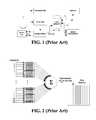
- a typical ultrasound imaging systemwill include the following main subsystems: a transmitter, a receiver, a receive focusing unit, a cine memory buffer, an image processor/display controller, a display unit, and a master controller.
- FIG. 1is a block diagram of a conventional ultrasound system for which the receive array focusing unit is referred to as a beamformer, and image formation is performed on a scan-line-by-scan-line basis.
- System controlis centered in the master controller, which accepts operator inputs through an operator interface and in turn controls the various subsystems.
- the transmitterFor each scan line, the transmitter generates a radio-frequency (RF) excitation voltage pulse waveform and applies it with appropriate timing across the transmit aperture (defined by a sub-array of active elements) to generate a focused acoustic beam along the scan line.
- RFradio-frequency
- RF echoes received by the receive aperture of the transducerare amplified and filtered by the receiver, and then fed into the beamformer, whose function is to perform dynamic receive focusing; i.e., to re-align the RF signals that originate from the same locations along various scan lines.
- the RF datais often converted (not shown) into baseband I/Q data before or after the beamformer.
- a synthetic array focusing approachsuch as shown in U.S. patent application Ser. No. 11/492,471, filed Jul. 24, 2006 for “Continuous Transmit Focusing Method And Apparatus For Ultrasound Imaging System” (David J. Napolitano et al.) is used for 2D imaging.
- a complete set of echo data obtained from a sequence of transmit-receive cyclesis accumulated in digital memory first, and then combined coherently in the receive focusing unit to produce the effect of having continuously focused transmit and receive beams throughout the image field.
- Other methods of synthetic focusinghave also been described in U.S. Pat. Nos. 4,604,697, 6,679,847, and 6,860,854, for both B-mode and flow imaging.
- the image processorperforms the processing specific to the active imaging mode(s) including 2D scan conversion that transforms the image data from an acoustic line grid to an X-Y pixel image for display.
- the image processorperforms wall-filtering followed by spectral analysis of Doppler-shifted signal samples using typically a sliding FFT-window. It is also responsible for generating the stereo audio signal output corresponding to forward and reverse flow signals.
- the image processoralso formats images from two or more active imaging modes, including display annotation, graphics overlays and replay of cine loops and recorded timeline data.
- the cine bufferprovides resident digital image storage for single image or multiple image loop review, and acts as a buffer for transfer of images to digital archival devices.
- the video images at the end of the data processing pathcan be stored 20 to the cine memory.
- amplitude-detected, beamformed datamay also be stored 22 in cine memory.
- some machinesstore the wall-filtered, baseband Doppler I/Q data for the user-selected range gate in cine memory, and the ZONARE z.one system stores the pre-wall-filtered data.
- U.S. Pat. No. 6,263,094describes a system wherein raw or partially processed data acquired early in the pipeline (pre-beamformed, post-beamformed, pre-video, etc.) is stored in non-volatile memory, and can be introduced into a signal processing system from memory at least at the rate that it was acquired, to produce a real time image that can be modified by the reviewer by further processing, if desired.
- the strict requirement of introducing the acoustic data at least at that particular rateis to ensure the real time playback is “as if the insonified target was the source of the acoustic data, not a storage device.” [4:30-31].
- the cost of storing Doppler data from earlier points in the receive data pathis greater cine memory capacity (or shorter image loops for the same memory size) and increased post-storage processing load (and response time).
- the benefitsare encapsulated by the concept of a “virtual patient;” i.e., the sonographer can focus on setting the probe over the region of interest, and storing the raw (i.e., unprocessed) Doppler data first. Then, during cine review, the operator can take time to re-adjust the image processing parameters based on the same data set (the “virtual patient”) without keeping the patient around longer than needed.
- the workflow and ergonomic advantages of such post-storage data processing capabilitiesare clear.
- U.S. Pat. No. 6,221,020describes a system wherein beamformed (I/Q or RF) data from a region of interest is accumulated 24 in cine memory during a storage period.
- the receive beamformingrefers to a weighted delay-and-sum operation, and the amplitude weighting across receive aperture is referred to as “apodization,” which is important for suppressing the sidelobes of the receive beam profile.
- This methodenables, during post-storage playback operation 25 , any known signal processing and system control which have conventionally been carried out in real-time during the scanning session.
- the usermay select any scan line and Doppler gate location and width within the region of interest for spectral Doppler or for color M-mode analysis.
- a limitation of this prior artis that the post-storage processing capabilities are restricted to conventional methods based on ultrasound data that is already beamformed.
- the sound speed parameter used for array focusing operationscan vary with different organ types and from patient to patient. Any sound speed optimization must be performed during the receive array focusing or reconstruction process.
- the ZONARE z.one systemsupports channel domain processing that first stores all the raw transducer element data in a channel domain memory, and then allows digital signal processor units to access the channel data multiple times in order to support an iterative algorithm that optimizes the array focusing sound speed.
- this kind of adaptive processingmay take up to a few seconds to complete while the rest of the signal pipeline is paused; i.e., the channel data is often read out by the signal processors multiple times and at a rate that may be lower than when it was acquired.
- the receive aperturewhich determines the receive F-number (defined by the ratio of focal range to aperture size), directly controls the degree of receive focusing.
- a lower F-numbermeans stronger focusing or a tighter beam width.
- a large aperturelow F-number can give rise to an increased velocity over-estimation errors—an effect referred to as geometrical spectral broadening.
- U.S. Pat. No. 6,679,847describes the synthetic focus system that stores raw channel data and applies different beamforming delay curves to track blood motion.
- This inventionis also aimed at providing flexible motion analyses and display methods, but it is fundamentally a pure synthetic focus system that utilizes single or small groups of elements for transmit (with known sensitivity challenges associated with limited acoustic power outputs) and requires an entire set of uncombined channel data to be stored for each image frame.
- the present inventionpertains to novel imaging capabilities in a post-storage mode, and is typically incorporated in an ultrasound imaging system that includes the following main subsystems: a transmitter, a receiver, a receive focusing unit, a cine memory buffer, an image processor/display controller, a display unit and a master controller.
- Embodiments of the present inventionprovide a system and method for accumulating partially reconstructed echo data from a region of interest during a storage period.
- the selection of the region of interestmay be effected via standard user interface control mechanisms (e.g. trackball and “set” buttons), based on a real-time background B-mode and/or color flow image display.
- the accumulated echo data representing the region of interestis then processed during a post-storage operation to provide a number of user-selectable and/or adaptive array focusing strategies, motion analysis and display modes.
- the systemfurther comprises front-panel controls that enable the user to select not only which retrospective processing method to be used, but also one or more spatial locations within the region of interest for such processing.
- the techniques for accumulating partially reconstructed echo data from a region of interest during the storage periodrepresent a commercially significant body of technology in their own right.
- the techniques for retrieving and processing the partially reconstructed data during the post-storage periodrepresent a commercially significant body of technology in their own right.
- the twowhich may be thought of as sub-combinations, should each be seen as a standalone aspect of the invention. While by definition accumulation and processing are done at different times, it is also contemplated that the two will often be done in different places by different entities.
- a number of advanced Doppler analysis and imaging methodscan benefit from this invention include Doppler spatial compounding for improved velocity estimation, dual-frequency Doppler for extended velocity range, dual timeline Doppler, multi-gate spectral flow imaging, strain-rate imaging and adaptive post-processing including adaptive clutter filtering and display parameters.
- the potential benefits of this inventioninclude not just all of the virtual patient capabilities, but also being able to analyze and process the same Doppler data using alternate processing and display methods aimed at extracting more diagnostic information.
- FIG. 1is a block diagram of a conventional ultrasound system
- FIG. 2is a block diagram showing prior art receive beamforming where a weighted delay-and-sum operation is performed
- FIG. 3is a block diagram of a specific embodiment of the present invention.
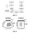
- FIG. 4shows a preferred embodiment showing a motion imaging region of interest (“ROI”) for a curved scan format (left portion of figure) and for a steered linear scan format (right portion of figure);
- ROImotion imaging region of interest
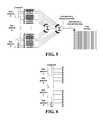
- FIG. 5shows a preferred embodiment in which the two receive sub-aperture channel sets are reconstructed and stored for each acoustic grid point
- FIG. 6shows a preferred embodiment in which the receive channels are divided into four sub-aperture groups for processing and storage
- FIG. 7shows a preferred embodiment in which the region of interest (smaller box) for which partially beamformed PW Doppler data is stored is a sub-region of the standard color flow region of interest (larger box), and also shows the time-line spectrograms for two Doppler sample volumes along separate PW Doppler lines being displayed side-by-side;
- FIG. 8shows an anatomical reconstruction line within the ROI
- FIG. 9shows multiple sample volumes for quantitative Doppler waveform analysis.
- FIG. 3is a block diagram of a preferred embodiment of the present invention for which system control is centered in a master controller that accepts operator inputs through an operator interface and in turn controls the various major data processing subsystems.
- a region of interest (“ROI”) for a motion imaging modee.g., spectral Doppler, color velocity and energy imaging, and Doppler tissue imaging
- ROIregion of interest
- a motion imaging modee.g., spectral Doppler, color velocity and energy imaging, and Doppler tissue imaging
- a corresponding scan formatis used to generate both the B-mode and motion imaging ROI.
- FIG. 4shows the examples of a curved and a linear array PW scan format, wherein the 2D motion imaging ROI defines a 2D acoustic grid for array focusing or reconstruction operations.
- the acoustic gridcomprises a set of scan lines as illustrated for the case of the curvilinear scan.
- ZONARE's imaging approachsee U.S. patent application Ser. No. 11/492,471
- the received data from all receive channels and transmit eventsare first accumulated into a channel domain memory unit (not shown), such that the array focusing can follow an arbitrary acoustic grid as illustrated for the case of the linear scan (notice the lateral and/or axial spacing do not even need to be uniform).
- the transmit-receive array focusing and steering strategies including the acoustic reconstruction gridare independent of those that constitute the background 2D image.
- this inventioncan be extended to 3D imaging such that the ROI refers to a 3D volume in space. That is, the ROI is not restricted to a 2D plane as shown in FIG. 4 .
- the ROIwould theoretically extend from the surface of the probe to infinite depth.
- the main functions of the transmitter and receiver in FIG. 3are to acquire a set of echo data from the ROI over a sufficiently long time interval such that motion effects can be measured.
- the ROIcan be divided into one or more transmit scan directions, and it is well known that the overall lateral spatial resolution is determined by the product of the transmit and receive array focusing response at each location.
- a number of repeated transmit-receive events at a user-selectable pulse repetition frequencyis used to interrogate moving sound reflectors along each transmit scan direction. That is, for each spatial location within the ROI, a packet of echo data samples from the repeated transmit-receive events is available for analysis. The number of data samples per packet is referred to as a “packet size.” For each packet, motion-induced echo changes from one sample to the next can be detected.
- a motion estimate(e.g., mean velocity) can be derived for each spatial location within the ROI, and the results can be translated into a 2D image, usually via a color mapping.
- various well known acquisition strategiesmay be used including multi-line and broad beam acquisition (one transmit broad beam spans two or more lateral positions in the acoustic reconstruction grid) and transmit interleaving (when the PRF is sufficient low such as for deep imaging, a transmit pulse may be fired along a different scan direction before the echo from the previous firing returns).
- the RF echoes received by the receive aperture of the transducerare amplified and filtered by the receiver.
- coded excitation methodsmay be used wherein the transmit encoder (not shown) repeats a transmit pulse multiple times according to a signal modulation or coding scheme and a receive decoder (not shown) compresses the received signal thereby restores the uncoded pulse resolution but with greater signal to noise ratio. It is well known to those skilled in the art that the receive decoding can be implemented before or after receive array focusing.
- the RF echo datais often converted (not shown) into baseband I/Q data before or after receive beamforming or array focusing.
- the received data from all receive channels and transmit eventscan be accumulated into a channel domain memory unit first prior to sub-aperture processing.
- image reconstructionwill be used in relation to the preferred embodiments of the present invention, as the channel domain processing involved is different and more general than conventional beamforming.
- a sub-aperturerefers to any subset (i.e., not necessarily contiguous) of the transducer elements that comprise the full receive aperture.
- a sub-aperturemay be defined by alternating elements across the physical array, or by alternating groups of 2 or more elements.
- the partially focused sub-aperture data setsare then stored in the cine memory such that during a post-storage period, the user can process and re-process the stored data with new degrees of flexibility not available with conventional systems. “Subset” in this context means at least one transducer element and fewer than all the transducer elements.
- one preferred embodimentis to divide the receive aperture into two groups: an inner sub-aperture group (A) and an outer sub-aperture group (B). Each group is combined taking into account of time delay, phase and amplitude weighting for optimal receive focusing.
- the receive aperturecan effectively be adjusted by applying different weightings to the inner and outer sub-aperture. For flow imaging, this provides a means for the user to adjust the tradeoff between flow sensitivity and geometrical spectral broadening error.
- a coarse sound speed tuningcan be realized by adjusting the relative time delays of the different sub-aperture groups during post-storage processing. That is, each sub-aperture group is regarded as a single receiver whose time delay is given by twice the distance between the center of the sub-aperture to the desired focus location, divided by an assumed sound speed value.
- This processcan also be automated by implementing an iterative algorithm in the image processor that combines (with appropriate time delays) the sub-aperture data set multiple times using a range of trial sound speed values, and automatically selects the best sound speed that yields the best focusing in terms of a pre-determined metric (e.g., signal energy within the focus region).
- a pre-determined metrice.g., signal energy within the focus region
- reconstructionis not limited to receive array focusing, but may incorporate synthetic transmit array focusing, especially for slow flow conditions. That is, improvements in transmit array focusing can be achieved retrospectively by coherently combining channel data acquired from different transmit events.
- the partially focused sub-aperture echo datacan be optionally compressed via a suitable encoding method to reduce the total amount of data for cine memory storage.
- the compressed datais first decoded or un-compressed prior to further processing. Since ultrasound echo data is correlated across channels, across range, and across spatially adjacent transmit firings, and in addition, in applications of color flow and spectral Doppler, the same reconstruction line is repeatedly sampled, there is a lot of redundant information present in raw echo data such that the opportunity for compression is great.
- Many encoding/decoding techniquesboth lossless and lossy, can be used including simple decimation, linear predictive coding, discrete cosine transform, and wavelet transform. Some of these methods treat the data as a sequence of one's and zero's.
- the cine datais stored in non-volatile media on the system.
- the cine data, with or without compressioncan be transferred to a remote workstation for post-processing and review.
- the data communications network connection to the remote review stationcan be a wireless network.
- One preferred embodiment of the present inventionpertains to post-storage CW Doppler imaging capabilities.
- a single transmit broad beamis used to define a relatively narrow ROI that may comprise two or more reconstruction lines as defined by receive array focusing. Since only one transmit beam is needed to scan the entire ROI, a CW transmit beam can be used, and partially focused sub-aperture receive channel groups of sampled I/Q data are stored in the cine memory.
- the I/Q datamay be sampled at 100 kHz.
- the usercan select via front-panel control of the system a specific CW Doppler line within the ROI for spectral analysis.
- the CW Doppler linecan be adjusted retrospectively after the raw data is acquired.
- this inventionalso enables post-storage user-adjustments of receive aperture (geometrical spectral broadening errors) and receive aperture focusing sound speed.
- a post-storage PW Doppler modewherein the sample gate position and/or receive aperture size can be retrospectively adjusted upon cine playback.
- One or more transmit beamsare used to define a ROI within which a specific sample gate can be selected retrospectively for spectral analysis. If the PRF is sufficiently low, two or more PW transmit-receive cycles can be interleaved; i.e., the PW transmit pulse for an adjacent beam can be fired while waiting for the echo to return from the previous firing. If the PRF is too high for interleaving, a single and broader transmit beam may be used such that it covers the entire ROI.
- the received channel data for each transmit firingare grouped according to the inner and outer sub-aperture scheme of FIG.
- any sample gate along any reconstruction line within the ROIcan be selected via front-panel controls for spectral Doppler analysis as in live PW spectral Doppler imaging.
- One exemplary applicationis, as shown in FIG. 7 , is to enable comparative and/or simultaneous blood flow analysis at two different locations relative to a stenosis in an artery.
- Two independent sample gates along two different reconstruction linescan be selected for spectral analysis, and the resultant time-line spectral waveforms can be displayed as a dual-image below the 2D color flow reference image.
- the receive aperture size for a selected PW Doppler linecan be adjusted by applying different weight factors to the partially focused inner and outer sub-aperture echo data.
- one or more transmit PW broad beamsare used to define the ROI.
- the received channel data for all transmit eventsare accumulated in a channel domain memory.
- programmable processorse.g., DSP chips, FPGA
- the sub-aperture reconstructionis no longer constrained to follow a set of scan lines as in a conventional hardware-based beamformer.
- the reconstructionfollows an “anatomical line” that can be specified via front-panel user-controls to be substantially normal to the near and far walls of a vessel of interest, instead of a conventional scan line that is parallel to the transmit-receive beam.
- an anatomical reconstruction lineis chosen to follow the geometry of the anatomy of interest (e.g., vessel cross-section) instead of a transmit-receive beam pattern.
- the usercan select any arbitrary sample gate along the anatomical reconstruction line for detailed spectral analysis.
- a plurality of sample gates along a selected anatomical linecan be processed in parallel to produce a dynamic spectral flow profile of range versus velocity, as taught by Tortoli et al. (1985), and also taught in U.S. Pat. No. 6,450,959.
- the usercan select two or more sample volumes in arbitrary positions within the ROI for quantitative spectral Doppler waveform index calculations during a post-storage period.
- FIG. 9Shown in FIG. 9 is an example in which a bifurcating artery is being studied by placing a sample volume in the common vessel and one in a branch vessel.
- the time-line spectral Doppler waveforms corresponding to the two sample volumescan be optionally displayed as a dual image below the 2D image (as in FIG. 7 ).
- An automated maximum envelope or mean velocity waveform tracing algorithmis implemented to track various spectral waveform indices such as maximum velocity (over a cardiac cycle) and the systolic to diastolic ratio.
- the maximum velocities for the two sample volumesare displayed below the 2D image.
- Another preferred embodiment of the present inventionis retrospective 2D color flow or tissue motion imaging.
- the acquisition strategies and optionsare similar to the aforementioned PW Doppler modes, except the display is in the form of a colorized flow image or a 2D grid of sample gates within the ROI.
- a packet of say, 10 transmit-receive eventsis acquired for each motion image frame, and another packet for the next frame etc.
- a 2D grid of sample gatesis analyzed serially or in parallel to estimate motion parameters such as mean velocity and motion signal energy.
- the processingmay include a motion-discrimination filtering step including a high-pass “clutter” filter for flow imaging, and a low-pass “flow-signal” filter for tissue motion imaging.
- the resultsare displayed using a pre-determined color map to provide a visual representation of the spatial distribution of the flow parameters within the ROI.
- Another preferred embodiment of the present inventioninvolves use of two or more independent sets of reconstruction lines that intersect each other within the ROI. It is well known to those skilled in the art that sub-aperture data obtained from two or more independent views of a sample volume can be combined to estimate the velocity vector (magnitude and direction) and/or to reduce estimation variance. By storing the sub-aperture data sets corresponding to different reconstruction lines in cine memory, the improved velocity estimation can be effected in a post-storage mode.
- an adaptive receive aperturecan be realized by prescribing weight factors for the two sub-aperture groups based on an estimate of the motion signal parameter (e.g., signal energy, mean or maximum Doppler frequency). If the flow signal is strong, the weighting on the outer sub-aperture group may be reduced relative to the inner sub-aperture group thereby reduce geometrical spectral broadening errors.
- the motion signal parametere.g., signal energy, mean or maximum Doppler frequency
Landscapes
- Health & Medical Sciences (AREA)
- Life Sciences & Earth Sciences (AREA)
- Engineering & Computer Science (AREA)
- Physics & Mathematics (AREA)
- Molecular Biology (AREA)
- General Health & Medical Sciences (AREA)
- Pathology (AREA)
- Radiology & Medical Imaging (AREA)
- Biophysics (AREA)
- Biomedical Technology (AREA)
- Heart & Thoracic Surgery (AREA)
- Medical Informatics (AREA)
- Veterinary Medicine (AREA)
- Surgery (AREA)
- Animal Behavior & Ethology (AREA)
- Nuclear Medicine, Radiotherapy & Molecular Imaging (AREA)
- Public Health (AREA)
- Radar, Positioning & Navigation (AREA)
- Remote Sensing (AREA)
- Computer Networks & Wireless Communication (AREA)
- General Physics & Mathematics (AREA)
- Acoustics & Sound (AREA)
- Computer Vision & Pattern Recognition (AREA)
- Vascular Medicine (AREA)
- Gynecology & Obstetrics (AREA)
- Physiology (AREA)
- Ultra Sonic Daignosis Equipment (AREA)
Abstract
Description
- U.S. Pat. No. 4,265,126: Papadofrangakis et al. (1981) “Measurement of true blood velocity by an ultrasound system.”
- U.S. Pat. No. 4,604,697: Luthra et al. (1986) “Body imaging using vectorial addition of acoustic reflection to achieve effect of scanning beam continuously focused in range.”
- U.S. Pat. No. 5,365,929: Peterson (1994) “Multiple sample volume spectral Doppler.”
- U.S. Pat. No. 5,409,010: Beach et al. (1995) “Vector Doppler medical devices for velocity studies.”
- U.S. Pat. No. 5,415,173: Miwa et al. (1995) “Ultrasound diagnosis system.”
- U.S. Pat. No. 5,690,111: Tsujino (1995) “Ultrasound diagnostic apparatus.”
- U.S. Pat. No. 6,221,020: Lysyansky et al. (2001) “System and method for providing variable ultrasound analyses in a post-storage mode.”
- U.S. Pat. No. 6,263,094: Rosich et al. (2001) “Acoustic data acquisition/playback system and method.”
- U.S. Pat. No. 6,450,959: Mo et al. (2002) “Ultrasound B-mode and Doppler flow imaging.”
- U.S. Pat. No. 6,679,847: Robinson et al. (2004) “Synthetically focused ultrasonic diagnostic imaging system for tissue and flow imaging.”
- U.S. Pat. No. 6,860,854: Robinson et al. (2005) “Synthetically focused ultrasonic diagnostic imaging system for tissue and flow imaging.”
- U.S. Pat. No. 6,926,671: Azuma et al. (2005) “Ultrasonic imaging apparatus and method.”
- U.S. patent application Ser. No. 11/492,471, filed Jul. 24, 2006: Napolitano et al. “Continuous Transmit Focusing Method And Apparatus For Ultrasound Imaging System.”
- Tortoli et al. (1985) “Velocity profile reconstruction using ultrafast spectral analysis of Doppler ultrasound.” IEEE Transactions Sonics and Ultrasonics, vol. SU-32, pp. 555-561.
- Nitzpon et al (1995) “New pulsed wave Doppler u/s system to measure blood velocities beyond the Nyquist limit.” IEEE Transactions Ultrason., Ferroelec. and Freq. Cntrl., vol. UFFC-42, pp. 265-279.
Claims (31)
Priority Applications (3)
| Application Number | Priority Date | Filing Date | Title |
|---|---|---|---|
| US12/340,578US9060669B1 (en) | 2007-12-20 | 2008-12-19 | System and method for providing variable ultrasound array processing in a post-storage mode |
| US14/748,084US10085724B2 (en) | 2007-12-20 | 2015-06-23 | System and method for providing variable ultrasound array processing in a post-storage mode |
| US16/015,581US11103221B2 (en) | 2007-12-20 | 2018-06-22 | System and method for providing variable ultrasound array processing in a post-storage mode |
Applications Claiming Priority (2)
| Application Number | Priority Date | Filing Date | Title |
|---|---|---|---|
| US1563207P | 2007-12-20 | 2007-12-20 | |
| US12/340,578US9060669B1 (en) | 2007-12-20 | 2008-12-19 | System and method for providing variable ultrasound array processing in a post-storage mode |
Related Child Applications (1)
| Application Number | Title | Priority Date | Filing Date |
|---|---|---|---|
| US14/748,084ContinuationUS10085724B2 (en) | 2007-12-20 | 2015-06-23 | System and method for providing variable ultrasound array processing in a post-storage mode |
Publications (1)
| Publication Number | Publication Date |
|---|---|
| US9060669B1true US9060669B1 (en) | 2015-06-23 |
Family
ID=53396979
Family Applications (3)
| Application Number | Title | Priority Date | Filing Date |
|---|---|---|---|
| US12/340,578Active2032-06-09US9060669B1 (en) | 2007-12-20 | 2008-12-19 | System and method for providing variable ultrasound array processing in a post-storage mode |
| US14/748,084ActiveUS10085724B2 (en) | 2007-12-20 | 2015-06-23 | System and method for providing variable ultrasound array processing in a post-storage mode |
| US16/015,581Active2029-10-05US11103221B2 (en) | 2007-12-20 | 2018-06-22 | System and method for providing variable ultrasound array processing in a post-storage mode |
Family Applications After (2)
| Application Number | Title | Priority Date | Filing Date |
|---|---|---|---|
| US14/748,084ActiveUS10085724B2 (en) | 2007-12-20 | 2015-06-23 | System and method for providing variable ultrasound array processing in a post-storage mode |
| US16/015,581Active2029-10-05US11103221B2 (en) | 2007-12-20 | 2018-06-22 | System and method for providing variable ultrasound array processing in a post-storage mode |
Country Status (1)
| Country | Link |
|---|---|
| US (3) | US9060669B1 (en) |
Cited By (18)
| Publication number | Priority date | Publication date | Assignee | Title |
|---|---|---|---|---|
| US20080146922A1 (en)* | 2006-10-24 | 2008-06-19 | Zonare Medical Systems, Inc. | Control of user interfaces and displays for portable ultrasound unit and docking station |
| US20170071576A1 (en)* | 2014-05-28 | 2017-03-16 | Shenzhen Mindray Bio-Medical Electronics Co., Ltd. | Ultrasound imaging method and system |
| US20170086780A1 (en)* | 2015-09-30 | 2017-03-30 | General Electric Company | Methods and systems for measuring cardiac output |
| US20170086789A1 (en)* | 2015-09-30 | 2017-03-30 | General Electric Company | Methods and systems for providing a mean velocity |
| CN107328869A (en)* | 2017-07-12 | 2017-11-07 | 辽宁红阳检测有限公司 | A kind of full information records supersonic detector |
| CN105455846B (en)* | 2015-12-16 | 2018-08-07 | 深圳开立生物医疗科技股份有限公司 | A kind of method, apparatus and ultrasonic system of storage diagnostic assistance information |
| US10085724B2 (en) | 2007-12-20 | 2018-10-02 | Shenzhen Mindray Bio-Medical Electronics Co., Ltd. | System and method for providing variable ultrasound array processing in a post-storage mode |
| JP2018183297A (en)* | 2017-04-24 | 2018-11-22 | コニカミノルタ株式会社 | Ultrasonic diagnostic device and ultrasonic signal processing method |
| US20200005452A1 (en)* | 2018-06-27 | 2020-01-02 | General Electric Company | Imaging system and method providing scalable resolution in multi-dimensional image data |
| US10542961B2 (en) | 2015-06-15 | 2020-01-28 | The Research Foundation For The State University Of New York | System and method for infrasonic cardiac monitoring |
| DE102018119206A1 (en)* | 2018-08-07 | 2020-02-13 | Salzgitter Mannesmann Forschung Gmbh | Method for detecting the geometry of an area of an object using ultrasound |
| US10754016B1 (en) | 2017-03-03 | 2020-08-25 | White Eagle Sonic Technologies, Inc. | Systems and methods for ultrasound phase adjustment |
| CN111820945A (en)* | 2019-04-16 | 2020-10-27 | 深圳迈瑞生物医疗电子股份有限公司 | System and method for performing ultrasound imaging |
| CN112731282A (en)* | 2020-12-09 | 2021-04-30 | 浙江工业大学 | Acoustic array spatial filtering method and system based on virtual subarray interleaving |
| US11109841B2 (en)* | 2018-12-06 | 2021-09-07 | General Electric Company | Method and system for simultaneously presenting doppler signals of a multi-gated doppler signal corresponding with different anatomical structures |
| US11259773B2 (en)* | 2016-06-30 | 2022-03-01 | Shenzhen Mindray Bio-Medical Electronics Co., Ltd. | Method and system for ultrasonic fluid spectral doppler imaging |
| US20220257218A1 (en)* | 2020-03-10 | 2022-08-18 | Yunnan University | Ultrasonic doppler blood flow imaging method and system |
| CN116807512A (en)* | 2023-07-14 | 2023-09-29 | 广东省智能科学与技术研究院 | Functional ultrasound imaging method, apparatus and readable storage medium |
Families Citing this family (7)
| Publication number | Priority date | Publication date | Assignee | Title |
|---|---|---|---|---|
| CN108761466B (en)* | 2018-05-17 | 2022-03-18 | 国网内蒙古东部电力有限公司检修分公司 | Wave beam domain generalized sidelobe cancellation ultrasonic imaging method |
| US11647989B2 (en) | 2018-09-11 | 2023-05-16 | Philips Image Guided Therapy Corporation | Devices, systems, and methods for multimodal ultrasound imaging |
| CN109490415A (en)* | 2018-11-30 | 2019-03-19 | 南京江淳机电装备科技有限公司 | A kind of pipe detection system of the multi-channel parallel excitation and acquisition of multi-frequency switching |
| US11523802B2 (en)* | 2018-12-16 | 2022-12-13 | Koninklijke Philips N.V. | Grating lobe artefact minimization for ultrasound images and associated devices, systems, and methods |
| US20210059644A1 (en)* | 2019-04-16 | 2021-03-04 | Shenzhen Mindray Bio-Medical Electronics Co., Ltd. | Retrospective multimodal high frame rate imaging |
| US11403732B2 (en)* | 2020-06-25 | 2022-08-02 | B-K Medical Aps | Ultrasound super resolution imaging |
| JP2023154619A (en)* | 2022-04-07 | 2023-10-20 | 富士フイルムヘルスケア株式会社 | Ultrasonic diagnostic device and beam formation method |
Citations (72)
| Publication number | Priority date | Publication date | Assignee | Title |
|---|---|---|---|---|
| US4265126A (en) | 1979-06-15 | 1981-05-05 | General Electric Company | Measurement of true blood velocity by an ultrasound system |
| US4604697A (en) | 1983-08-05 | 1986-08-05 | Interspec, Inc. | Body imaging using vectorial addition of acoustic reflection to achieve effect of scanning beam continuously focused in range |
| US4852577A (en) | 1988-04-07 | 1989-08-01 | The United States Of America As Represented By The Department Of Health And Human Services | High speed adaptive ultrasonic phased array imaging system |
| US4852576A (en) | 1985-04-02 | 1989-08-01 | Elscint Ltd. | Time gain compensation for ultrasonic medical imaging systems |
| US5161535A (en) | 1991-06-24 | 1992-11-10 | Hewlett-Packard Company | Medical ultrasound imaging system having a partitioned menu |
| US5260871A (en) | 1991-07-31 | 1993-11-09 | Mayo Foundation For Medical Education And Research | Method and apparatus for diagnosis of breast tumors |
| US5269289A (en) | 1990-12-25 | 1993-12-14 | Olympus Optical Co., Ltd. | Cavity insert device using fuzzy theory |
| US5313948A (en) | 1991-11-28 | 1994-05-24 | Aloka Co., Ltd. | Ultrasonic diagnostic apparatus |
| US5357965A (en) | 1993-11-24 | 1994-10-25 | General Electric Company | Method for controlling adaptive color flow processing using fuzzy logic |
| US5357962A (en) | 1992-01-27 | 1994-10-25 | Sri International | Ultrasonic imaging system and method wtih focusing correction |
| US5365929A (en) | 1993-10-04 | 1994-11-22 | Advanced Technology Laboratories, Inc. | Multiple sample volume spectral Doppler |
| US5409010A (en) | 1992-05-19 | 1995-04-25 | Board Of Regents Of The University Of Washington | Vector doppler medical devices for blood velocity studies |
| US5415173A (en) | 1993-02-23 | 1995-05-16 | Hitachi, Ltd. | Ultrasound diagnosis system |
| US5417215A (en) | 1994-02-04 | 1995-05-23 | Long Island Jewish Medical Center | Method of tissue characterization by ultrasound |
| US5555534A (en) | 1994-08-05 | 1996-09-10 | Acuson Corporation | Method and apparatus for doppler receive beamformer system |
| US5566674A (en) | 1995-06-30 | 1996-10-22 | Siemens Medical Systems, Inc. | Method and apparatus for reducing ultrasound image shadowing and speckle |
| US5581517A (en) | 1994-08-05 | 1996-12-03 | Acuson Corporation | Method and apparatus for focus control of transmit and receive beamformer systems |
| US5579768A (en) | 1995-03-21 | 1996-12-03 | Acuson Corporation | Automatic gain compensation in an ultrasound imaging system |
| US5617862A (en)* | 1995-05-02 | 1997-04-08 | Acuson Corporation | Method and apparatus for beamformer system with variable aperture |
| US5623928A (en) | 1994-08-05 | 1997-04-29 | Acuson Corporation | Method and apparatus for coherent image formation |
| US5654509A (en) | 1996-05-08 | 1997-08-05 | Hewlett-Packard Company | Control system that distinguishes between imaging and nonimaging environments in an ultrasound system |
| US5690111A (en) | 1994-12-27 | 1997-11-25 | Kabushiki Kaisha Toshiba | Ultrasound diagnostic apparatus |
| US5720289A (en) | 1994-08-05 | 1998-02-24 | Acuson Corporation | Method and apparatus for a geometric aberration transform in an adaptive focusing ultrasound beamformer system |
| US5776063A (en) | 1996-09-30 | 1998-07-07 | Molecular Biosystems, Inc. | Analysis of ultrasound images in the presence of contrast agent |
| US5782766A (en) | 1995-03-31 | 1998-07-21 | Siemens Medical Systems, Inc. | Method and apparatus for generating and displaying panoramic ultrasound images |
| US5799111A (en) | 1991-06-14 | 1998-08-25 | D.V.P. Technologies, Ltd. | Apparatus and methods for smoothing images |
| US5857973A (en) | 1997-09-30 | 1999-01-12 | Siemens Medical Systems, Inc. | Fuzzy logic tissue flow determination system |
| US5871019A (en) | 1996-09-23 | 1999-02-16 | Mayo Foundation For Medical Education And Research | Fast cardiac boundary imaging |
| US5935074A (en) | 1997-10-06 | 1999-08-10 | General Electric Company | Method and apparatus for automatic tracing of Doppler time-velocity waveform envelope |
| US5954653A (en) | 1997-05-07 | 1999-09-21 | General Electric Company | Method and apparatus for automatically enhancing contrast in projected ultrasound image |
| US5984870A (en) | 1997-07-25 | 1999-11-16 | Arch Development Corporation | Method and system for the automated analysis of lesions in ultrasound images |
| US5993393A (en)* | 1992-07-14 | 1999-11-30 | Intravascular Research Limited | Methods and apparatus for the examination and treatment of internal organs |
| US6016285A (en) | 1994-08-05 | 2000-01-18 | Acuson Corporation | Method and apparatus for coherent image formation |
| US6036643A (en) | 1998-05-14 | 2000-03-14 | Advanced Technology Laboratories, Inc. | Ultrasonic harmonic doppler imaging |
| US6042545A (en)* | 1998-11-25 | 2000-03-28 | Acuson Corporation | Medical diagnostic ultrasound system and method for transform ultrasound processing |
| US6068598A (en) | 1998-12-01 | 2000-05-30 | General Electric Company | Method and apparatus for automatic Doppler angle estimation in ultrasound imaging |
| US6069593A (en) | 1998-02-24 | 2000-05-30 | Motorola, Inc. | Display carrier and electronic display control for multiple displays in a portable electronic device |
| US6102859A (en) | 1998-12-01 | 2000-08-15 | General Electric Company | Method and apparatus for automatic time and/or lateral gain compensation in B-mode ultrasound imaging |
| US6110119A (en) | 1998-12-31 | 2000-08-29 | General Electric Company | Ultrasound color flow imaging utilizing a plurality of algorithms |
| US6113544A (en) | 1998-12-07 | 2000-09-05 | Mo; Larry Y. L. | Method and apparatus for automatic transmit waveform optimization in B-mode ultrasound imaging |
| US6120446A (en) | 1998-12-17 | 2000-09-19 | Acuson Corporation | Diagnostic medical ultrasonic imaging system and method with adaptive gain |
| US6142943A (en) | 1998-12-30 | 2000-11-07 | General Electric Company | Doppler ultrasound automatic spectrum optimization |
| US6162176A (en) | 1998-12-31 | 2000-12-19 | General Electric Company | Ultrasound color flow display optimization |
| US6193663B1 (en) | 1997-12-18 | 2001-02-27 | Acuson Corporation | Diagnostic ultrasound imaging method and system with improved frame rate |
| US6221020B1 (en) | 1999-04-22 | 2001-04-24 | G.E. Medical Systems Global Technology Company, Llc | System and method for providing variable ultrasound analyses in a post-storage mode |
| US6263094B1 (en) | 1999-04-02 | 2001-07-17 | Agilent Technologies, Inc. | Acoustic data acquisition/playback system and method |
| US6312385B1 (en) | 2000-05-01 | 2001-11-06 | Ge Medical Systems Global Technology Company, Llc | Method and apparatus for automatic detection and sizing of cystic objects |
| US6315728B1 (en) | 1999-12-21 | 2001-11-13 | General Electric Company | Ultrasound color flow adaptive scanning techniques |
| US6358205B1 (en) | 1999-08-05 | 2002-03-19 | Acuson Corporation | Medical diagnostic ultrasonic imaging system with adaptive front-end gain and adaptive transmitter gain |
| US6390983B1 (en) | 1999-07-09 | 2002-05-21 | Ge Medical Systems Global Technology Company, Llc | Method and apparatus for automatic muting of Doppler noise induced by ultrasound probe motion |
| US6398733B1 (en) | 2000-04-24 | 2002-06-04 | Acuson Corporation | Medical ultrasonic imaging system with adaptive multi-dimensional back-end mapping |
| US6423003B1 (en) | 1999-10-29 | 2002-07-23 | Acuson Corporation | Ultrasonic imaging system and method with SNR adaptive processing |
| US6434262B2 (en) | 1993-09-29 | 2002-08-13 | Shih-Ping Wang | Computer-aided diagnosis system and method |
| US6450959B1 (en) | 2000-03-23 | 2002-09-17 | Ge Medical Systems Global Technology Company | Ultrasound B-mode and doppler flow imaging |
| US6464637B1 (en) | 2000-06-23 | 2002-10-15 | Koninklijke Philips Electronics N.V. | Automatic flow angle correction by ultrasonic vector |
| US6464641B1 (en) | 1998-12-01 | 2002-10-15 | Ge Medical Systems Global Technology Company Llc | Method and apparatus for automatic vessel tracking in ultrasound imaging |
| US6464640B1 (en) | 1996-12-04 | 2002-10-15 | Acuson Corporation | Methods and apparatus for ultrasound imaging with automatic color image positioning |
| US6468218B1 (en) | 2001-08-31 | 2002-10-22 | Siemens Medical Systems, Inc. | 3-D ultrasound imaging system and method |
| US6491636B2 (en) | 2000-12-07 | 2002-12-10 | Koninklijke Philips Electronics N.V. | Automated border detection in ultrasonic diagnostic images |
| US6497661B1 (en) | 2001-07-31 | 2002-12-24 | Koninklijke Philips Electronics N.V. | Portable ultrasound diagnostic device with automatic data transmission |
| US6503203B1 (en) | 2001-01-16 | 2003-01-07 | Koninklijke Philips Electronics N.V. | Automated ultrasound system for performing imaging studies utilizing ultrasound contrast agents |
| US6512854B1 (en) | 1999-05-07 | 2003-01-28 | Koninklijke Philips Electronics N.V. | Adaptive control and signal enhancement of an ultrasound display |
| US6547737B2 (en) | 2000-01-14 | 2003-04-15 | Philip Chidi Njemanze | Intelligent transcranial doppler probe |
| US6577967B2 (en) | 1998-12-31 | 2003-06-10 | General Electric Company | Automatic adjustment of velocity scale and pulse repetition frequency for doppler ultrasound spectrograms |
| US6679847B1 (en) | 2002-04-30 | 2004-01-20 | Koninklijke Philips Electronics N.V. | Synthetically focused ultrasonic diagnostic imaging system for tissue and flow imaging |
| US20040179332A1 (en) | 2003-03-12 | 2004-09-16 | Zonare Medical Systems. Inc. | Portable ultrasound unit and docking station |
| US6926671B2 (en) | 2002-02-05 | 2005-08-09 | Hitachi Medical Corporation | Ultrasonic imaging apparatus and method |
| US6932770B2 (en) | 2003-08-04 | 2005-08-23 | Prisma Medical Technologies Llc | Method and apparatus for ultrasonic imaging |
| US7022075B2 (en) | 1999-08-20 | 2006-04-04 | Zonare Medical Systems, Inc. | User interface for handheld imaging devices |
| US20060074320A1 (en) | 2004-08-27 | 2006-04-06 | Yoo Yang M | Home ultrasound system |
| US20060079778A1 (en) | 2004-10-07 | 2006-04-13 | Zonare Medical Systems, Inc. | Ultrasound imaging system parameter optimization via fuzzy logic |
| WO2008051738A2 (en) | 2006-10-24 | 2008-05-02 | Zonare Medical Systems, Inc. | Control of user interfaces and displays for portable ultrasound unit and docking station |
Family Cites Families (5)
| Publication number | Priority date | Publication date | Assignee | Title |
|---|---|---|---|---|
| US5638820A (en)* | 1996-06-25 | 1997-06-17 | Siemens Medical Systems, Inc. | Ultrasound system for estimating the speed of sound in body tissue |
| US20060106309A1 (en)* | 2004-11-16 | 2006-05-18 | Siemens Medical Solutions Usa, Inc. | Aberration correction beam patterns |
| US8784318B1 (en) | 2005-07-22 | 2014-07-22 | Zonare Medical Systems, Inc. | Aberration correction using channel data in ultrasound imaging system |
| US8002705B1 (en) | 2005-07-22 | 2011-08-23 | Zonaire Medical Systems, Inc. | Continuous transmit focusing method and apparatus for ultrasound imaging system |
| US9060669B1 (en) | 2007-12-20 | 2015-06-23 | Zonare Medical Systems, Inc. | System and method for providing variable ultrasound array processing in a post-storage mode |
- 2008
- 2008-12-19USUS12/340,578patent/US9060669B1/enactiveActive
- 2015
- 2015-06-23USUS14/748,084patent/US10085724B2/enactiveActive
- 2018
- 2018-06-22USUS16/015,581patent/US11103221B2/enactiveActive
Patent Citations (79)
| Publication number | Priority date | Publication date | Assignee | Title |
|---|---|---|---|---|
| US4265126A (en) | 1979-06-15 | 1981-05-05 | General Electric Company | Measurement of true blood velocity by an ultrasound system |
| US4604697A (en) | 1983-08-05 | 1986-08-05 | Interspec, Inc. | Body imaging using vectorial addition of acoustic reflection to achieve effect of scanning beam continuously focused in range |
| US4852576A (en) | 1985-04-02 | 1989-08-01 | Elscint Ltd. | Time gain compensation for ultrasonic medical imaging systems |
| US4852577A (en) | 1988-04-07 | 1989-08-01 | The United States Of America As Represented By The Department Of Health And Human Services | High speed adaptive ultrasonic phased array imaging system |
| US5269289A (en) | 1990-12-25 | 1993-12-14 | Olympus Optical Co., Ltd. | Cavity insert device using fuzzy theory |
| US5799111A (en) | 1991-06-14 | 1998-08-25 | D.V.P. Technologies, Ltd. | Apparatus and methods for smoothing images |
| US5161535A (en) | 1991-06-24 | 1992-11-10 | Hewlett-Packard Company | Medical ultrasound imaging system having a partitioned menu |
| US5260871A (en) | 1991-07-31 | 1993-11-09 | Mayo Foundation For Medical Education And Research | Method and apparatus for diagnosis of breast tumors |
| US5313948A (en) | 1991-11-28 | 1994-05-24 | Aloka Co., Ltd. | Ultrasonic diagnostic apparatus |
| US5357962A (en) | 1992-01-27 | 1994-10-25 | Sri International | Ultrasonic imaging system and method wtih focusing correction |
| US5409010A (en) | 1992-05-19 | 1995-04-25 | Board Of Regents Of The University Of Washington | Vector doppler medical devices for blood velocity studies |
| US5993393A (en)* | 1992-07-14 | 1999-11-30 | Intravascular Research Limited | Methods and apparatus for the examination and treatment of internal organs |
| US5415173A (en) | 1993-02-23 | 1995-05-16 | Hitachi, Ltd. | Ultrasound diagnosis system |
| US6434262B2 (en) | 1993-09-29 | 2002-08-13 | Shih-Ping Wang | Computer-aided diagnosis system and method |
| US5365929A (en) | 1993-10-04 | 1994-11-22 | Advanced Technology Laboratories, Inc. | Multiple sample volume spectral Doppler |
| US5357965A (en) | 1993-11-24 | 1994-10-25 | General Electric Company | Method for controlling adaptive color flow processing using fuzzy logic |
| US5417215A (en) | 1994-02-04 | 1995-05-23 | Long Island Jewish Medical Center | Method of tissue characterization by ultrasound |
| US5555534A (en) | 1994-08-05 | 1996-09-10 | Acuson Corporation | Method and apparatus for doppler receive beamformer system |
| US5581517A (en) | 1994-08-05 | 1996-12-03 | Acuson Corporation | Method and apparatus for focus control of transmit and receive beamformer systems |
| US5623928A (en) | 1994-08-05 | 1997-04-29 | Acuson Corporation | Method and apparatus for coherent image formation |
| US6016285A (en) | 1994-08-05 | 2000-01-18 | Acuson Corporation | Method and apparatus for coherent image formation |
| US5720289A (en) | 1994-08-05 | 1998-02-24 | Acuson Corporation | Method and apparatus for a geometric aberration transform in an adaptive focusing ultrasound beamformer system |
| US5690111A (en) | 1994-12-27 | 1997-11-25 | Kabushiki Kaisha Toshiba | Ultrasound diagnostic apparatus |
| US5579768A (en) | 1995-03-21 | 1996-12-03 | Acuson Corporation | Automatic gain compensation in an ultrasound imaging system |
| US5782766A (en) | 1995-03-31 | 1998-07-21 | Siemens Medical Systems, Inc. | Method and apparatus for generating and displaying panoramic ultrasound images |
| US5617862A (en)* | 1995-05-02 | 1997-04-08 | Acuson Corporation | Method and apparatus for beamformer system with variable aperture |
| US5566674A (en) | 1995-06-30 | 1996-10-22 | Siemens Medical Systems, Inc. | Method and apparatus for reducing ultrasound image shadowing and speckle |
| US5654509A (en) | 1996-05-08 | 1997-08-05 | Hewlett-Packard Company | Control system that distinguishes between imaging and nonimaging environments in an ultrasound system |
| US5871019A (en) | 1996-09-23 | 1999-02-16 | Mayo Foundation For Medical Education And Research | Fast cardiac boundary imaging |
| US5776063A (en) | 1996-09-30 | 1998-07-07 | Molecular Biosystems, Inc. | Analysis of ultrasound images in the presence of contrast agent |
| US6464640B1 (en) | 1996-12-04 | 2002-10-15 | Acuson Corporation | Methods and apparatus for ultrasound imaging with automatic color image positioning |
| US5954653A (en) | 1997-05-07 | 1999-09-21 | General Electric Company | Method and apparatus for automatically enhancing contrast in projected ultrasound image |
| US5984870A (en) | 1997-07-25 | 1999-11-16 | Arch Development Corporation | Method and system for the automated analysis of lesions in ultrasound images |
| US5857973A (en) | 1997-09-30 | 1999-01-12 | Siemens Medical Systems, Inc. | Fuzzy logic tissue flow determination system |
| US5935074A (en) | 1997-10-06 | 1999-08-10 | General Electric Company | Method and apparatus for automatic tracing of Doppler time-velocity waveform envelope |
| US6193663B1 (en) | 1997-12-18 | 2001-02-27 | Acuson Corporation | Diagnostic ultrasound imaging method and system with improved frame rate |
| US6069593A (en) | 1998-02-24 | 2000-05-30 | Motorola, Inc. | Display carrier and electronic display control for multiple displays in a portable electronic device |
| US6036643A (en) | 1998-05-14 | 2000-03-14 | Advanced Technology Laboratories, Inc. | Ultrasonic harmonic doppler imaging |
| US6042545A (en)* | 1998-11-25 | 2000-03-28 | Acuson Corporation | Medical diagnostic ultrasound system and method for transform ultrasound processing |
| US6464641B1 (en) | 1998-12-01 | 2002-10-15 | Ge Medical Systems Global Technology Company Llc | Method and apparatus for automatic vessel tracking in ultrasound imaging |
| US6102859A (en) | 1998-12-01 | 2000-08-15 | General Electric Company | Method and apparatus for automatic time and/or lateral gain compensation in B-mode ultrasound imaging |
| US6068598A (en) | 1998-12-01 | 2000-05-30 | General Electric Company | Method and apparatus for automatic Doppler angle estimation in ultrasound imaging |
| US6113544A (en) | 1998-12-07 | 2000-09-05 | Mo; Larry Y. L. | Method and apparatus for automatic transmit waveform optimization in B-mode ultrasound imaging |
| US6120446A (en) | 1998-12-17 | 2000-09-19 | Acuson Corporation | Diagnostic medical ultrasonic imaging system and method with adaptive gain |
| US6142943A (en) | 1998-12-30 | 2000-11-07 | General Electric Company | Doppler ultrasound automatic spectrum optimization |
| US6577967B2 (en) | 1998-12-31 | 2003-06-10 | General Electric Company | Automatic adjustment of velocity scale and pulse repetition frequency for doppler ultrasound spectrograms |
| US6162176A (en) | 1998-12-31 | 2000-12-19 | General Electric Company | Ultrasound color flow display optimization |
| US6110119A (en) | 1998-12-31 | 2000-08-29 | General Electric Company | Ultrasound color flow imaging utilizing a plurality of algorithms |
| US6263094B1 (en) | 1999-04-02 | 2001-07-17 | Agilent Technologies, Inc. | Acoustic data acquisition/playback system and method |
| US6221020B1 (en) | 1999-04-22 | 2001-04-24 | G.E. Medical Systems Global Technology Company, Llc | System and method for providing variable ultrasound analyses in a post-storage mode |
| US6512854B1 (en) | 1999-05-07 | 2003-01-28 | Koninklijke Philips Electronics N.V. | Adaptive control and signal enhancement of an ultrasound display |
| US6390983B1 (en) | 1999-07-09 | 2002-05-21 | Ge Medical Systems Global Technology Company, Llc | Method and apparatus for automatic muting of Doppler noise induced by ultrasound probe motion |
| US6358205B1 (en) | 1999-08-05 | 2002-03-19 | Acuson Corporation | Medical diagnostic ultrasonic imaging system with adaptive front-end gain and adaptive transmitter gain |
| US7022075B2 (en) | 1999-08-20 | 2006-04-04 | Zonare Medical Systems, Inc. | User interface for handheld imaging devices |
| US6423003B1 (en) | 1999-10-29 | 2002-07-23 | Acuson Corporation | Ultrasonic imaging system and method with SNR adaptive processing |
| US6315728B1 (en) | 1999-12-21 | 2001-11-13 | General Electric Company | Ultrasound color flow adaptive scanning techniques |
| US6547737B2 (en) | 2000-01-14 | 2003-04-15 | Philip Chidi Njemanze | Intelligent transcranial doppler probe |
| US6450959B1 (en) | 2000-03-23 | 2002-09-17 | Ge Medical Systems Global Technology Company | Ultrasound B-mode and doppler flow imaging |
| US6398733B1 (en) | 2000-04-24 | 2002-06-04 | Acuson Corporation | Medical ultrasonic imaging system with adaptive multi-dimensional back-end mapping |
| US6322509B1 (en) | 2000-05-01 | 2001-11-27 | Ge Medical Systems Global Technology Company, Llc | Method and apparatus for automatic setting of sample gate in pulsed doppler ultrasound imaging |
| US6312385B1 (en) | 2000-05-01 | 2001-11-06 | Ge Medical Systems Global Technology Company, Llc | Method and apparatus for automatic detection and sizing of cystic objects |
| US6464637B1 (en) | 2000-06-23 | 2002-10-15 | Koninklijke Philips Electronics N.V. | Automatic flow angle correction by ultrasonic vector |
| US6491636B2 (en) | 2000-12-07 | 2002-12-10 | Koninklijke Philips Electronics N.V. | Automated border detection in ultrasonic diagnostic images |
| US6503203B1 (en) | 2001-01-16 | 2003-01-07 | Koninklijke Philips Electronics N.V. | Automated ultrasound system for performing imaging studies utilizing ultrasound contrast agents |
| US6497661B1 (en) | 2001-07-31 | 2002-12-24 | Koninklijke Philips Electronics N.V. | Portable ultrasound diagnostic device with automatic data transmission |
| US6468218B1 (en) | 2001-08-31 | 2002-10-22 | Siemens Medical Systems, Inc. | 3-D ultrasound imaging system and method |
| US6926671B2 (en) | 2002-02-05 | 2005-08-09 | Hitachi Medical Corporation | Ultrasonic imaging apparatus and method |
| US6679847B1 (en) | 2002-04-30 | 2004-01-20 | Koninklijke Philips Electronics N.V. | Synthetically focused ultrasonic diagnostic imaging system for tissue and flow imaging |
| US6860854B2 (en) | 2002-04-30 | 2005-03-01 | Koninklijke Philips Electronics N.V. | Synthetically focused ultrasonic diagnostic imaging system for tissue and flow imaging |
| US20040068188A1 (en)* | 2002-04-30 | 2004-04-08 | Robinson Brent S. | Synthetically focused ultrasonic diagnostic imaging system for tissue and flow imaging |
| US20040179332A1 (en) | 2003-03-12 | 2004-09-16 | Zonare Medical Systems. Inc. | Portable ultrasound unit and docking station |
| US6980419B2 (en) | 2003-03-12 | 2005-12-27 | Zonare Medical Systems, Inc. | Portable ultrasound unit and docking station |
| US6932770B2 (en) | 2003-08-04 | 2005-08-23 | Prisma Medical Technologies Llc | Method and apparatus for ultrasonic imaging |
| US20060074320A1 (en) | 2004-08-27 | 2006-04-06 | Yoo Yang M | Home ultrasound system |
| US20060079778A1 (en) | 2004-10-07 | 2006-04-13 | Zonare Medical Systems, Inc. | Ultrasound imaging system parameter optimization via fuzzy logic |
| US7627386B2 (en) | 2004-10-07 | 2009-12-01 | Zonaire Medical Systems, Inc. | Ultrasound imaging system parameter optimization via fuzzy logic |
| US20100189329A1 (en) | 2004-10-07 | 2010-07-29 | Zonare Medical Systems Inc. | Ultrasound Imaging System Parameter Optimization Via Fuzzy Logic |
| WO2008051738A2 (en) | 2006-10-24 | 2008-05-02 | Zonare Medical Systems, Inc. | Control of user interfaces and displays for portable ultrasound unit and docking station |
| US20080146922A1 (en) | 2006-10-24 | 2008-06-19 | Zonare Medical Systems, Inc. | Control of user interfaces and displays for portable ultrasound unit and docking station |
Non-Patent Citations (22)
| Title |
|---|
| Anderson, M.E., et al., "The Impact of Sound Speed Errors on Medical Ultrasound Imaging", J. Acous. Soc. of Am., Jun. 2000, pp. 3540-3548, vol. 107, No. 6. |
| Freeman, S., "Retrospective Dynamic Transmit Focusing", Ultrasonic Imaging 17, 1995, pp. 173-196. |
| Gammelmark, K.L., et al. "Multi-Element Synthetic Transmit Aperture Imaging using Temporal Encoding", 2002 SPIE Medical Imaging Meeting, Ultrasonic Imaging and Signal Processing, 2002; pp. 25-36. |
| Haider, B., "Synthetic Transmit Focusing for Ultrasound Imaging", 2000 IEEE Ultrasonics Symposium, pp. 1215-1218. |
| Haun, Mark Alden, "New Approached to Aberration Correction in Medical Ultrasound Imaging", Ph.D. Thesis, University of Illinois at Urbana-Champaign, 2003, 134 pages. |
| Hergum, T., et al., "Parallel Beamforming using Synthetic Transmit Beams", 2004 IEEE International Ultrasonics, Ferroelectrics, and Frequency Control Joint 50th Anniversary Conference, pp. 1401-1404. |
| International Search Report and Written Opinion of Apr. 3, 2008 for PCT Application No. PCT/US07/81253, 9 pages. |
| Jellins, J. et al., "Velocity compensation in water-coupled breast echography", Ultrasonics, Sep. 1973, pp. 223-226. |
| Liu, D., et al., "Adaptive Ultrasonic Imaging Using SONOLINE Elegra(TM)", 2000 IEEE Ultrasonics Symposium, 4 pages. |
| Liu, D., et al., "Adaptive Ultrasonic Imaging Using SONOLINE Elegra™", 2000 IEEE Ultrasonics Symposium, 4 pages. |
| Nitzpon, P., et al., "New Pulsed Wave Doppler Ultrasound System to Measure Blood Velocities Beyond the Nyquist Limit," 1995, IEEE Transactions Ultrasonics and Ferroelectrics, and Frequency Control, vol. 42, No. 2, pp. 265-279. |
| Nock, L., et al., "Phase aberration correction in medical ultrasound using speckle brightness as a quality factor", J. Acous. Soc. Am., May 1989, vol. 85, No. 5, pp. 1819-1833. |
| Notice of Allowance of May 15, 2009 for U.S. Appl. No. 10/961,709, 8 pages. |
| Office Action of Aug. 3, 2010 for U.S. Appl. No. 11/586,212, 8 pages. |
| Office Action of Dec. 2, 2008 for U.S. Appl. No. 10/961,709, 4 pages. |
| Office Action of Feb. 3, 2009 for U.S. Appl. No. 11/492,557, 15 pages. |
| Office Action of Jun. 24, 2010 for U.S. Appl. No. 11/492,471, 11 pages. |
| Office Action of Nov. 5, 2010 for U.S. Appl. No. 12/628,169, 8 pages. |
| Office Action of Oct. 27, 2009 for U.S. Appl. No. 11/492,557, 14 pages. |
| Office Action of Sep. 14, 2007 for U.S. Appl. No. 10/961,709, 6 pages. |
| Robinson, B., et al., "Synthetic Dynamic Transmit Focus", 2000 IEEE Ultrasonics Symposium, pp. 1209-1214. |
| Tortoli, P., et al., "Velocity Profile Reconstruction Using Ultrafast Spectral Analysis of Doppler Ultrasound," IEEE Transactions Sonics and Ultrasonics, vol. SU-32, No. 2, pp. 555-561, 1985. |
Cited By (28)
| Publication number | Priority date | Publication date | Assignee | Title |
|---|---|---|---|---|
| US20080146922A1 (en)* | 2006-10-24 | 2008-06-19 | Zonare Medical Systems, Inc. | Control of user interfaces and displays for portable ultrasound unit and docking station |
| US11103221B2 (en) | 2007-12-20 | 2021-08-31 | Shenzhen Mindray Bio-Medical Electronics Co., Ltd. | System and method for providing variable ultrasound array processing in a post-storage mode |
| US10085724B2 (en) | 2007-12-20 | 2018-10-02 | Shenzhen Mindray Bio-Medical Electronics Co., Ltd. | System and method for providing variable ultrasound array processing in a post-storage mode |
| US20170071576A1 (en)* | 2014-05-28 | 2017-03-16 | Shenzhen Mindray Bio-Medical Electronics Co., Ltd. | Ultrasound imaging method and system |
| US11259784B2 (en)* | 2014-05-28 | 2022-03-01 | Shenzhen Mindray Bio-Medical Electronics Co., Ltd. | Ultrasound imaging method and system |
| US11826205B2 (en) | 2014-05-28 | 2023-11-28 | Shenzhen Mindray Bio-Medical Electronics Co., Ltd. | Ultrasound imaging method and system |
| US11478215B2 (en) | 2015-06-15 | 2022-10-25 | The Research Foundation for the State University o | System and method for infrasonic cardiac monitoring |
| US10542961B2 (en) | 2015-06-15 | 2020-01-28 | The Research Foundation For The State University Of New York | System and method for infrasonic cardiac monitoring |
| US10206651B2 (en)* | 2015-09-30 | 2019-02-19 | General Electric Company | Methods and systems for measuring cardiac output |
| US20170086789A1 (en)* | 2015-09-30 | 2017-03-30 | General Electric Company | Methods and systems for providing a mean velocity |
| US20170086780A1 (en)* | 2015-09-30 | 2017-03-30 | General Electric Company | Methods and systems for measuring cardiac output |
| CN105455846B (en)* | 2015-12-16 | 2018-08-07 | 深圳开立生物医疗科技股份有限公司 | A kind of method, apparatus and ultrasonic system of storage diagnostic assistance information |
| US11903757B2 (en) | 2016-06-30 | 2024-02-20 | Shenzhen Mindray Bio-Medical Electronics Co., Ltd. | Method and system for ultrasonic fluid spectral doppler imaging |
| US11963819B2 (en) | 2016-06-30 | 2024-04-23 | Shenzhen Mindray Bio-Medical Electronics Co., Ltd. | Method and system for ultrasonic fluid spectral doppler imaging |
| US11259773B2 (en)* | 2016-06-30 | 2022-03-01 | Shenzhen Mindray Bio-Medical Electronics Co., Ltd. | Method and system for ultrasonic fluid spectral doppler imaging |
| US10754016B1 (en) | 2017-03-03 | 2020-08-25 | White Eagle Sonic Technologies, Inc. | Systems and methods for ultrasound phase adjustment |
| JP2018183297A (en)* | 2017-04-24 | 2018-11-22 | コニカミノルタ株式会社 | Ultrasonic diagnostic device and ultrasonic signal processing method |
| CN107328869A (en)* | 2017-07-12 | 2017-11-07 | 辽宁红阳检测有限公司 | A kind of full information records supersonic detector |
| US10685439B2 (en)* | 2018-06-27 | 2020-06-16 | General Electric Company | Imaging system and method providing scalable resolution in multi-dimensional image data |
| US20200005452A1 (en)* | 2018-06-27 | 2020-01-02 | General Electric Company | Imaging system and method providing scalable resolution in multi-dimensional image data |
| DE102018119206A1 (en)* | 2018-08-07 | 2020-02-13 | Salzgitter Mannesmann Forschung Gmbh | Method for detecting the geometry of an area of an object using ultrasound |
| DE102018119206B4 (en)* | 2018-08-07 | 2024-08-08 | Salzgitter Mannesmann Forschung Gmbh | Method for detecting a geometry of a region of an object using ultrasound |
| US11109841B2 (en)* | 2018-12-06 | 2021-09-07 | General Electric Company | Method and system for simultaneously presenting doppler signals of a multi-gated doppler signal corresponding with different anatomical structures |
| CN111820945A (en)* | 2019-04-16 | 2020-10-27 | 深圳迈瑞生物医疗电子股份有限公司 | System and method for performing ultrasound imaging |
| US20220257218A1 (en)* | 2020-03-10 | 2022-08-18 | Yunnan University | Ultrasonic doppler blood flow imaging method and system |
| CN112731282A (en)* | 2020-12-09 | 2021-04-30 | 浙江工业大学 | Acoustic array spatial filtering method and system based on virtual subarray interleaving |
| CN112731282B (en)* | 2020-12-09 | 2023-12-26 | 浙江工业大学 | Acoustic array spatial filtering method and system based on virtual subarray interleaving |
| CN116807512A (en)* | 2023-07-14 | 2023-09-29 | 广东省智能科学与技术研究院 | Functional ultrasound imaging method, apparatus and readable storage medium |
Also Published As
| Publication number | Publication date |
|---|---|
| US20160051233A1 (en) | 2016-02-25 |
| US10085724B2 (en) | 2018-10-02 |
| US20180368813A1 (en) | 2018-12-27 |
| US11103221B2 (en) | 2021-08-31 |
Similar Documents
| Publication | Publication Date | Title |
|---|---|---|
| US11103221B2 (en) | System and method for providing variable ultrasound array processing in a post-storage mode | |
| US12167209B2 (en) | Ultrasound imaging system memory architecture | |
| US11678861B2 (en) | Ultrasound imaging system memory architecture | |
| KR101820422B1 (en) | High frame rate quantitative doppler flow imaging using unfocused transmit beams | |
| JP6932192B2 (en) | Methods and systems for filtering ultrasound image clutter | |
| US20070161898A1 (en) | Raw data reprocessing in ultrasound diagnostic imaging | |
| US9366753B2 (en) | Systems and methods for ultrasound retrospective transmit focus beamforming | |
| US11346929B2 (en) | Systems and methods for ultrafast ultrasound imaging | |
| KR102014946B1 (en) | Enhanced ultrasound image formation system and method using qualified regions of overlapping transmit beams | |
| JP2007222253A (en) | Blood flow image display device | |
| Nikolov et al. | Practical applications of synthetic aperture imaging | |
| US11950960B2 (en) | Ultrasound imaging with deep learning-based beamforming and associated devices, systems, and methods | |
| JP7583839B2 (en) | Method and system for data transmission reduction in ultrasound imaging - Patents.com | |
| US8235906B2 (en) | System and method for accelerated focused ultrasound imaging | |
| CN112334072A (en) | Method and system for performing color doppler ultrasound imaging | |
| Martin | Basic equipment, components and image production | |
| CN113454484B (en) | Ultrasound imaging with deep learning-based beamforming and associated devices, systems, and methods | |
| HK40063952A (en) | Ultrasound imaging system memory architecture | |
| Tasinkevych | 3D Ultrasonography in Real Time: Image Reconstruction Methods | |
| HK1208330B (en) | Method of ultrasound imaging |
Legal Events
| Date | Code | Title | Description |
|---|---|---|---|
| AS | Assignment | Owner name:ZONARE MEDICAL SYSTEMS, INC., CALIFORNIA Free format text:ASSIGNMENT OF ASSIGNORS INTEREST;ASSIGNORS:MO, LARRY Y.L.;MCLAUGHLIN, GLEN W.;DEBUSSCHERE, BRIAN DEREK;AND OTHERS;SIGNING DATES FROM 20081229 TO 20090123;REEL/FRAME:022170/0048 | |
| STCF | Information on status: patent grant | Free format text:PATENTED CASE | |
| AS | Assignment | Owner name:SHENZHEN MINDRAY BIO-MEDICAL ELECTRONICS CO., LTD. Free format text:ASSIGNMENT OF ASSIGNORS INTEREST;ASSIGNOR:ZONARE MEDICAL SYSTEMS, INC.;REEL/FRAME:036322/0876 Effective date:20150811 | |
| AS | Assignment | Owner name:SHENZHEN MINDRAY BIO-MEDICAL ELECTRONICS CO., LTD, CHINA Free format text:ASSIGNMENT OF ASSIGNORS INTEREST;ASSIGNOR:ZONARE MEDICAL SYSTEMS, INC.;REEL/FRAME:044613/0734 Effective date:20150811 Owner name:SHENZHEN MINDRAY BIO-MEDICAL ELECTRONICS CO., LTD, Free format text:ASSIGNMENT OF ASSIGNORS INTEREST;ASSIGNOR:ZONARE MEDICAL SYSTEMS, INC.;REEL/FRAME:044613/0734 Effective date:20150811 | |
| AS | Assignment | Owner name:SHENZHEN MINDRAY BIO-MEDICAL ELECTRONICS CO., LTD, CHINA Free format text:ASSIGNMENT OF ASSIGNORS INTEREST;ASSIGNOR:ZONARE MEDICAL SYSTEMS, INC.;REEL/FRAME:044625/0530 Effective date:20150811 Owner name:SHENZHEN MINDRAY BIO-MEDICAL ELECTRONICS CO., LTD, Free format text:ASSIGNMENT OF ASSIGNORS INTEREST;ASSIGNOR:ZONARE MEDICAL SYSTEMS, INC.;REEL/FRAME:044625/0530 Effective date:20150811 | |
| FEPP | Fee payment procedure | Free format text:MAINTENANCE FEE REMINDER MAILED (ORIGINAL EVENT CODE: REM.); ENTITY STATUS OF PATENT OWNER: LARGE ENTITY | |
| FEPP | Fee payment procedure | Free format text:SURCHARGE FOR LATE PAYMENT, LARGE ENTITY (ORIGINAL EVENT CODE: M1554); ENTITY STATUS OF PATENT OWNER: LARGE ENTITY | |
| MAFP | Maintenance fee payment | Free format text:PAYMENT OF MAINTENANCE FEE, 4TH YEAR, LARGE ENTITY (ORIGINAL EVENT CODE: M1551); ENTITY STATUS OF PATENT OWNER: LARGE ENTITY Year of fee payment:4 | |
| AS | Assignment | Owner name:SHENZHEN MINDRAY ANIMAL MEDICAL TECHNOLOGY CO., LTD., CHINA Free format text:LICENSE;ASSIGNOR:SHENZHEN MINDRAY BIOMEDICAL ELECTRONICS CO., LTD.;REEL/FRAME:060440/0796 Effective date:20220601 | |
| MAFP | Maintenance fee payment | Free format text:PAYMENT OF MAINTENANCE FEE, 8TH YEAR, LARGE ENTITY (ORIGINAL EVENT CODE: M1552); ENTITY STATUS OF PATENT OWNER: LARGE ENTITY Year of fee payment:8 |