US9058910B2 - Charged particle beam acceleration method and apparatus as part of a charged particle cancer therapy system - Google Patents
Charged particle beam acceleration method and apparatus as part of a charged particle cancer therapy systemDownload PDFInfo
- Publication number
- US9058910B2 US9058910B2US12/994,117US99411709AUS9058910B2US 9058910 B2US9058910 B2US 9058910B2US 99411709 AUS99411709 AUS 99411709AUS 9058910 B2US9058910 B2US 9058910B2
- Authority
- US
- United States
- Prior art keywords
- turning
- synchrotron
- magnets
- magnetic field
- protons
- Prior art date
- Legal status (The legal status is an assumption and is not a legal conclusion. Google has not performed a legal analysis and makes no representation as to the accuracy of the status listed.)
- Expired - Fee Related, expires
Links
- 239000002245particleSubstances0.000titleclaimsabstractdescription84
- 238000000034methodMethods0.000titleabstractdescription30
- 230000001133accelerationEffects0.000titleabstractdescription18
- 238000011275oncology therapyMethods0.000titledescription5
- 206010028980NeoplasmDiseases0.000claimsabstractdescription72
- 238000004804windingMethods0.000claimsdescription40
- 238000012937correctionMethods0.000claimsdescription39
- 238000005452bendingMethods0.000claimsdescription26
- 238000002560therapeutic procedureMethods0.000claimsdescription17
- 239000012141concentrateSubstances0.000claimsdescription4
- 238000000605extractionMethods0.000abstractdescription64
- 238000001959radiotherapyMethods0.000abstractdescription3
- 238000010884ion-beam techniqueMethods0.000description96
- 150000002500ionsChemical class0.000description48
- 239000011888foilSubstances0.000description39
- 230000029058respiratory gaseous exchangeEffects0.000description28
- 239000000463materialSubstances0.000description24
- 239000013598vectorSubstances0.000description22
- 210000001519tissueAnatomy0.000description21
- 230000004888barrier functionEffects0.000description19
- 230000033001locomotionEffects0.000description19
- XEEYBQQBJWHFJM-UHFFFAOYSA-NIronChemical compound[Fe]XEEYBQQBJWHFJM-UHFFFAOYSA-N0.000description18
- 230000005684electric fieldEffects0.000description18
- 230000008685targetingEffects0.000description15
- UFHFLCQGNIYNRP-UHFFFAOYSA-NHydrogenChemical compound[H][H]UFHFLCQGNIYNRP-UHFFFAOYSA-N0.000description12
- 230000000694effectsEffects0.000description12
- 238000002347injectionMethods0.000description12
- 239000007924injectionSubstances0.000description12
- 230000008569processEffects0.000description12
- 229910052742ironInorganic materials0.000description9
- 230000001965increasing effectEffects0.000description8
- 238000012544monitoring processMethods0.000description8
- 230000008859changeEffects0.000description7
- 230000007423decreaseEffects0.000description7
- 239000001257hydrogenSubstances0.000description7
- 229910052739hydrogenInorganic materials0.000description7
- 238000003384imaging methodMethods0.000description7
- 239000000696magnetic materialSubstances0.000description7
- 229910052799carbonInorganic materials0.000description6
- 230000006870functionEffects0.000description6
- 239000007789gasSubstances0.000description6
- 230000015654memoryEffects0.000description6
- 230000010355oscillationEffects0.000description6
- OKTJSMMVPCPJKN-UHFFFAOYSA-NCarbonChemical compound[C]OKTJSMMVPCPJKN-UHFFFAOYSA-N0.000description4
- CURLTUGMZLYLDI-UHFFFAOYSA-NCarbon dioxideChemical compoundO=C=OCURLTUGMZLYLDI-UHFFFAOYSA-N0.000description4
- 230000006378damageEffects0.000description4
- 238000013461designMethods0.000description4
- -1hydrogen anionChemical class0.000description4
- 238000002661proton therapyMethods0.000description4
- IJGRMHOSHXDMSA-UHFFFAOYSA-NAtomic nitrogenChemical compoundN#NIJGRMHOSHXDMSA-UHFFFAOYSA-N0.000description3
- 230000008901benefitEffects0.000description3
- 238000006243chemical reactionMethods0.000description3
- 230000001351cycling effectEffects0.000description3
- 230000004907fluxEffects0.000description3
- 230000001678irradiating effectEffects0.000description3
- 238000007726management methodMethods0.000description3
- 230000005855radiationEffects0.000description3
- 239000007787solidSubstances0.000description3
- 230000001225therapeutic effectEffects0.000description3
- YZCKVEUIGOORGS-UHFFFAOYSA-NHydrogen atomChemical compound[H]YZCKVEUIGOORGS-UHFFFAOYSA-N0.000description2
- 230000000712assemblyEffects0.000description2
- 238000000429assemblyMethods0.000description2
- 125000004429atomChemical group0.000description2
- 229910052790berylliumInorganic materials0.000description2
- ATBAMAFKBVZNFJ-UHFFFAOYSA-Nberyllium atomChemical compound[Be]ATBAMAFKBVZNFJ-UHFFFAOYSA-N0.000description2
- 239000001569carbon dioxideSubstances0.000description2
- 229910002092carbon dioxideInorganic materials0.000description2
- 239000004020conductorSubstances0.000description2
- 125000004122cyclic groupChemical group0.000description2
- 230000001419dependent effectEffects0.000description2
- 238000009826distributionMethods0.000description2
- 210000002216heartAnatomy0.000description2
- 238000005286illuminationMethods0.000description2
- 210000004072lungAnatomy0.000description2
- 238000004519manufacturing processMethods0.000description2
- 230000035515penetrationEffects0.000description2
- 230000037081physical activityEffects0.000description2
- 230000000241respiratory effectEffects0.000description2
- 230000001020rhythmical effectEffects0.000description2
- 230000006641stabilisationEffects0.000description2
- 238000011105stabilizationMethods0.000description2
- 238000003860storageMethods0.000description2
- 230000001360synchronised effectEffects0.000description2
- 239000013077target materialSubstances0.000description2
- 230000000007visual effectEffects0.000description2
- WHXSMMKQMYFTQS-UHFFFAOYSA-NLithiumChemical compound[Li]WHXSMMKQMYFTQS-UHFFFAOYSA-N0.000description1
- 230000003321amplificationEffects0.000description1
- 230000005540biological transmissionEffects0.000description1
- 230000000903blocking effectEffects0.000description1
- 230000035565breathing frequencyEffects0.000description1
- 201000011510cancerDiseases0.000description1
- 230000005779cell damageEffects0.000description1
- 208000037887cell injuryDiseases0.000description1
- 239000000919ceramicSubstances0.000description1
- 238000004891communicationMethods0.000description1
- 230000006835compressionEffects0.000description1
- 238000007906compressionMethods0.000description1
- 239000000470constituentSubstances0.000description1
- 230000008878couplingEffects0.000description1
- 238000010168coupling processMethods0.000description1
- 238000005859coupling reactionMethods0.000description1
- 230000003247decreasing effectEffects0.000description1
- 230000008021depositionEffects0.000description1
- 230000001627detrimental effectEffects0.000description1
- 239000006185dispersionSubstances0.000description1
- 230000005672electromagnetic fieldEffects0.000description1
- 230000002708enhancing effectEffects0.000description1
- 239000000284extractSubstances0.000description1
- 150000002431hydrogenChemical class0.000description1
- GPRLSGONYQIRFK-UHFFFAOYSA-NhydronChemical compound[H+]GPRLSGONYQIRFK-UHFFFAOYSA-N0.000description1
- 239000012535impuritySubstances0.000description1
- 238000001727in vivoMethods0.000description1
- 210000003734kidneyAnatomy0.000description1
- 239000003562lightweight materialSubstances0.000description1
- 229910000103lithium hydrideInorganic materials0.000description1
- 210000004185liverAnatomy0.000description1
- 230000005381magnetic domainEffects0.000description1
- 238000012423maintenanceMethods0.000description1
- 229910052751metalInorganic materials0.000description1
- 239000002184metalSubstances0.000description1
- 229910052757nitrogenInorganic materials0.000description1
- JCXJVPUVTGWSNB-UHFFFAOYSA-Nnitrogen dioxideInorganic materialsO=[N]=OJCXJVPUVTGWSNB-UHFFFAOYSA-N0.000description1
- 238000003199nucleic acid amplification methodMethods0.000description1
- 230000003287optical effectEffects0.000description1
- 210000000056organAnatomy0.000description1
- 238000002727particle therapyMethods0.000description1
- 210000002976pectoralis muscleAnatomy0.000description1
- 230000002093peripheral effectEffects0.000description1
- 239000004033plasticSubstances0.000description1
- 238000005086pumpingMethods0.000description1
- 230000002285radioactive effectEffects0.000description1
- 230000009467reductionEffects0.000description1
- 230000008439repair processEffects0.000description1
- 230000036387respiratory rateEffects0.000description1
- 239000000523sampleSubstances0.000description1
- 238000007789sealingMethods0.000description1
- 210000003491skinAnatomy0.000description1
- 125000006850spacer groupChemical group0.000description1
- 230000000087stabilizing effectEffects0.000description1
- 210000002784stomachAnatomy0.000description1
- 239000013589supplementSubstances0.000description1
- 210000000115thoracic cavityAnatomy0.000description1
- 238000003325tomographyMethods0.000description1
- 238000012546transferMethods0.000description1
- 238000013519translationMethods0.000description1
- 238000012795verificationMethods0.000description1
- 210000001835visceraAnatomy0.000description1
- 239000011800void materialSubstances0.000description1
- 229910000859α-FeInorganic materials0.000description1
Images


Classifications
- G—PHYSICS
- G21—NUCLEAR PHYSICS; NUCLEAR ENGINEERING
- G21K—TECHNIQUES FOR HANDLING PARTICLES OR IONISING RADIATION NOT OTHERWISE PROVIDED FOR; IRRADIATION DEVICES; GAMMA RAY OR X-RAY MICROSCOPES
- G21K1/00—Arrangements for handling particles or ionising radiation, e.g. focusing or moderating
- G21K1/08—Deviation, concentration or focusing of the beam by electric or magnetic means
- G21K1/087—Deviation, concentration or focusing of the beam by electric or magnetic means by electrical means
- G—PHYSICS
- G21—NUCLEAR PHYSICS; NUCLEAR ENGINEERING
- G21K—TECHNIQUES FOR HANDLING PARTICLES OR IONISING RADIATION NOT OTHERWISE PROVIDED FOR; IRRADIATION DEVICES; GAMMA RAY OR X-RAY MICROSCOPES
- G21K1/00—Arrangements for handling particles or ionising radiation, e.g. focusing or moderating
- G21K1/08—Deviation, concentration or focusing of the beam by electric or magnetic means
- G21K1/093—Deviation, concentration or focusing of the beam by electric or magnetic means by magnetic means
- G—PHYSICS
- G21—NUCLEAR PHYSICS; NUCLEAR ENGINEERING
- G21K—TECHNIQUES FOR HANDLING PARTICLES OR IONISING RADIATION NOT OTHERWISE PROVIDED FOR; IRRADIATION DEVICES; GAMMA RAY OR X-RAY MICROSCOPES
- G21K1/00—Arrangements for handling particles or ionising radiation, e.g. focusing or moderating
- G21K1/14—Arrangements for handling particles or ionising radiation, e.g. focusing or moderating using charge exchange devices, e.g. for neutralising or changing the sign of the electrical charges of beams
- H—ELECTRICITY
- H05—ELECTRIC TECHNIQUES NOT OTHERWISE PROVIDED FOR
- H05H—PLASMA TECHNIQUE; PRODUCTION OF ACCELERATED ELECTRICALLY-CHARGED PARTICLES OR OF NEUTRONS; PRODUCTION OR ACCELERATION OF NEUTRAL MOLECULAR OR ATOMIC BEAMS
- H05H13/00—Magnetic resonance accelerators; Cyclotrons
- H05H13/04—Synchrotrons
- H—ELECTRICITY
- H05—ELECTRIC TECHNIQUES NOT OTHERWISE PROVIDED FOR
- H05H—PLASMA TECHNIQUE; PRODUCTION OF ACCELERATED ELECTRICALLY-CHARGED PARTICLES OR OF NEUTRONS; PRODUCTION OR ACCELERATION OF NEUTRAL MOLECULAR OR ATOMIC BEAMS
- H05H7/00—Details of devices of the types covered by groups H05H9/00, H05H11/00, H05H13/00
- H05H7/04—Magnet systems, e.g. undulators, wigglers; Energisation thereof
- H—ELECTRICITY
- H05—ELECTRIC TECHNIQUES NOT OTHERWISE PROVIDED FOR
- H05H—PLASMA TECHNIQUE; PRODUCTION OF ACCELERATED ELECTRICALLY-CHARGED PARTICLES OR OF NEUTRONS; PRODUCTION OR ACCELERATION OF NEUTRAL MOLECULAR OR ATOMIC BEAMS
- H05H7/00—Details of devices of the types covered by groups H05H9/00, H05H11/00, H05H13/00
- H05H7/08—Arrangements for injecting particles into orbits
- H—ELECTRICITY
- H05—ELECTRIC TECHNIQUES NOT OTHERWISE PROVIDED FOR
- H05H—PLASMA TECHNIQUE; PRODUCTION OF ACCELERATED ELECTRICALLY-CHARGED PARTICLES OR OF NEUTRONS; PRODUCTION OR ACCELERATION OF NEUTRAL MOLECULAR OR ATOMIC BEAMS
- H05H7/00—Details of devices of the types covered by groups H05H9/00, H05H11/00, H05H13/00
- H05H7/10—Arrangements for ejecting particles from orbits
- A—HUMAN NECESSITIES
- A61—MEDICAL OR VETERINARY SCIENCE; HYGIENE
- A61N—ELECTROTHERAPY; MAGNETOTHERAPY; RADIATION THERAPY; ULTRASOUND THERAPY
- A61N5/00—Radiation therapy
- A61N5/10—X-ray therapy; Gamma-ray therapy; Particle-irradiation therapy
- A61N2005/1085—X-ray therapy; Gamma-ray therapy; Particle-irradiation therapy characterised by the type of particles applied to the patient
- A61N2005/1087—Ions; Protons
Definitions
- This inventionrelates generally to treatment of solid cancers. More particularly, the invention relates to an ion beam acceleration system, which is used in conjunction with charged particle cancer therapy beam injection, extraction, and/or targeting methods and apparatus.
- Proton therapy systemstypically include: a beam generator, an accelerator, and a beam transport system to move the resulting accelerated protons to a treatment room where the protons are delivered to a tumor in a patient's body.
- Proton therapyworks by aiming energetic ionizing particles, such as protons accelerated with a particle accelerator, onto a target tumor. These particles damage the DNA of cells, ultimately causing their death. Cancerous cells, because of their high rate of division and their reduced ability to repair damaged DNA, are particularly vulnerable to attacks on their DNA.
- energetic ionizing particlessuch as protons accelerated with a particle accelerator
- protons of a given energyhave a certain range, defined by the Bragg peak, and the dosage delivery to tissue ratio is at a maximum over just the last few millimeters of the particle's range.
- the penetration depthdepends on the energy of the particles, which is directly related to the speed to which the particles were accelerated by the proton accelerator.
- the speed of the protonis adjustable to the maximum rating of the accelerator. It is therefore possible to focus the cell damage due to the proton beam at the very depth in the tissues where the tumor is situated. Tissues situated before the Bragg peak receive some reduced dose and tissues situated after the peak receive none.
- K. Hiramoto, et. al. “Accelerator System”, U.S. Pat. No. 4,870,287 (Sep. 26, 1989)describes an accelerator system having a selector electromagnet for introducing an ion beam accelerated by pre-accelerators into either a radioisotope producing unit or a synchrotron.
- a synchrotronhaving combined function magnets and a radio frequency (RF) cavity accelerator.
- the combined function magnetsfunction to first bend the particle beam along an orbital path and second focus the particle beam.
- the RF cavity acceleratoris a ferrite loaded cavity adapted for high speed frequency swings for rapid cycling particle acceleration.
- the ion beam systemuses a gantry that has a vertical deflection system and a horizontal deflection system positioned before a last bending magnet that result in a parallel scanning mode resulting from an edge focusing effect.
- the deviceconsists of an electromagnet undulation system, whose driving system for electromagnets is made in the form of a radio-frequency (RF) oscillator operating in the frequency range from about 100 KHz to 10 GHz.
- RFradio-frequency
- M. Tadokoro, et. al. “Electromagnetic and Magnetic Field Generating Apparatus”, U.S. Pat. No. 6,365,894 (Apr. 2, 2002) and M. Tadokoro, et. al. “Electromagnetic and Magnetic Field Generating Apparatus”, U.S. Pat. No. 6,236,043 (May 22, 2001)each describe a pair of magnetic poles, a return yoke, and exciting coils. The interior of the magnetic poles each have a plurality of air gap spacers to increase magnetic field strength.
- Y. Nagamine, et. al. “Patient Positioning Device and Patient Positioning Method”, U.S. Pat. No. 7,212,609 (May 1, 2007) and Y. Nagamine, et. al. “Patient Positioning Device and Patient Positioning Method”, U.S. Pat. No. 7,212,608 (May 1, 2007)describe a patient positioning system that compares a comparison area of a reference X-ray image and a current X-ray image of a current patient location using pattern matching.
- 6,792,078(Sep. 14, 2004) all describe a system of leaf plates used to shorten positioning time of a patient for irradiation therapy. Motor driving force is transmitted to a plurality of leaf plates at the same time through a pinion gear.
- the systemalso uses upper and lower air cylinders and upper and lower guides to position a patient.
- the inventioncomprises a particle beam accelerator, which is part of a charged particle cancer therapy beam system.
- FIG. 1illustrates component connections of a particle beam therapy system
- FIG. 2illustrates a charged particle therapy system
- FIG. 3illustrates an ion beam generation system
- FIG. 4illustrates a negative ion beam source
- FIG. 5illustrates an ion beam focusing system
- FIGS. 6 A-Dillustrate electrodes about a negative ion beam path
- FIG. 7Aillustrates a tandem accelerator having a foil
- 7 Billustrates a support structure
- 7 Cillustrates a conversion foil
- FIG. 8is a synchrotron control flowchart
- FIG. 9illustrates straight and turning sections of a synchrotron
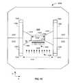
- FIG. 10illustrates bending magnets of a synchrotron
- FIG. 11provides a perspective view of a bending magnet
- FIG. 12illustrates a cross-sectional view of a bending magnet
- FIG. 13illustrates a cross-sectional view of a bending magnet
- FIG. 14illustrates magnetic field concentration in a bending magnet
- FIG. 15illustrates correction coils in a bending magnet
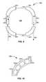
- FIG. 16illustrates a magnetic turning section of a synchrotron
- FIG. 17illustrates a magnetic field control system
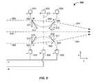
- FIG. 18illustrates a charged particle extraction and intensity control system
- FIG. 19illustrates a patient positioning system from: (A) a front view and (B) a top view;
- FIG. 20illustrates multi-dimensional scanning of a charged particle beam spot scanning system operating on: (A) a 2-D slice or (B) a 3-D volume of a tumor.
- the inventionrelates generally to treatment of solid cancers. More particularly, the invention relates to a method and apparatus for accelerating a charged particle beam in a synchrotron.
- synchrotron advancementsare described resulting in a small footprint accelerator.
- turning magnets, edge focusing magnets, magnetic field concentration magnets, and extraction elementsare described that minimize the overall size of the synchrotron, provide a tightly controlled proton beam, directly reduce the size of required magnetic fields, directly reduces required operating power, and allow continual acceleration of protons in a synchrotron even during a process of extracting protons from the synchrotron.
- the synchrotronhas:
- the optional ion beam injection systempreferably includes several components, including a negative ion source, an ion beam focusing system, a two part vacuum system, and a tandem accelerator.
- the negative ion sourcepreferably includes an inlet port for injection of hydrogen gas into a high temperature plasma chamber, a magnetic material, which provides a magnetic field barrier between the high temperature plasma chamber and a low temperature plasma region on the opposite side of the magnetic field barrier.
- An extraction pulseis applied to a negative ion extraction electrode to pull the negative ion beam into a negative ion beam path, which proceeds through a first partial vacuum system, through an ion beam focusing system, into the tandem accelerator, and into a synchrotron after conversion to a proton beam at a converting foil.
- the ion beam source system and synchrotronare preferably computer integrated with a patient interface module including respiration monitoring sensors to synchronize charged particle delivery with a set period of a patient's respiration cycle.
- a cyclotronuses a constant magnetic field and a constant-frequency applied electric field. One of the two fields is varied in a synchrocyclotron. Both of these fields are varied in a synchrotron.
- a synchrotronis a particular type of cyclic particle accelerator in which a magnetic field is used to turn the particles so they circulate and an electric field is used to accelerate the particles. The synchroton carefully synchronizes the applied fields with the travelling particle beam.
- the charged particles pathcan be held constant as they are accelerated.
- Thisallows the vacuum container for the particles to be a large thin torus.
- a path of large effective radiusis thus constructed using simple straight and curved pipe segments, unlike the disc-shaped chamber of the cyclotron type devices.
- the shapealso allows and requires the use of multiple magnets to bend the particle beam.
- the maximum energy that a cyclic accelerator can impartis typically limited by the strength of the magnetic fields and the minimum radius/maximum curvature, of the particle path.
- the maximum radiusis quite limited as the particles start at the center and spiral outward, thus this entire path must be a self-supporting disc-shaped evacuated chamber. Since the radius is limited, the power of the machine becomes limited by the strength of the magnetic field. In the case of an ordinary electromagnet, the field strength is limited by the saturation of the core because when all magnetic domains are aligned the field may not be further increased to any practical extent. The arrangement of the single pair of magnets also limits the economic size of the device.
- Synchrotronsovercome these limitations, using a narrow beam pipe surrounded by much smaller and more tightly focusing magnets.
- the ability of this device to accelerate particlesis limited by the fact that the particles must be charged to be accelerated at all, but charged particles under acceleration emit photons, thereby losing energy.
- the limiting beam energyis reached when the energy lost to the lateral acceleration required to maintain the beam path in a circle equals the energy added each cycle.
- More powerful acceleratorsare built by using large radius paths and by using more numerous and more powerful microwave cavities to accelerate the particle beam between corners. Lighter particles, such as electrons, lose a larger fraction of their energy when turning. Practically speaking, the energy of electron/positron accelerators is limited by this radiation loss, while it does not play a significant role in the dynamics of proton or ion accelerators. The energy of those is limited strictly by the strength of magnets and by the cost.
- a charged particle beam therapy systemsuch as a proton beam, hydrogen ion beam, or carbon ion beam
- the charged particle beam therapy systemis described using a proton beam.
- the aspects taught and described in terms of a proton beamare not intended to be limiting to that of a proton beam and are illustrative of a charged particle beam system. Any charged particle beam system is equally applicable to the techniques described herein.
- the charged particle beampreferably comprises a number of subsystems including any of: a main controller 110 ; an injection system 120 ; a synchrotron 130 that typically includes: (1) an accelerator system 132 and (2) an extraction system 134 ; a scanning/targeting/delivery system 140 ; a patient interface module 150 ; a display system 160 ; and/or an imaging system 170 .
- one or more of the subsystemsare stored on a client.
- the clientis a computing platform configured to act as a client device, e.g. a personal computer, a digital media player, a personal digital assistant, etc.
- the clientcomprises a processor that is coupled to a number of external or internal inputting devices, e.g. a mouse, a keyboard, a display device, etc.
- the processoris also coupled to an output device, e.g. a computer monitor to display information.
- the main controller 110is the processor.
- the main controller 110is a set of instructions stored in memory that is carried out by the processor.
- the clientincludes a computer-readable storage medium, i.e. memory.
- the memoryincludes, but is not limited to, an electronic, optical, magnetic, or another storage or transmission device capable of coupling to a processor, e.g. such as a processor in communication with a touch-sensitive input device, with computer-readable instructions.
- a processore.g. such as a processor in communication with a touch-sensitive input device, with computer-readable instructions.
- suitable mediainclude, for example, flash drive, CD-ROM, read only memory (ROM), random access memory (RAM), application-specific integrated circuit (ASIC), DVD, magnetic disk, memory chip, etc.
- the processorexecutes a set of computer-executable program code instructions stored in the memory.
- the instructionsmay comprise code from any computer-programming language, including, for example, C, C++, C#, Visual Basic, Java, and JavaScript.
- the main controller 110controls one or more of the subsystems to accurately and precisely deliver protons to a tumor of a patient. For example, the main controller 110 obtains an image, such as a portion of a body and/or of a tumor, from the imaging system 170 . The main controller 110 also obtains position and/or timing information from the patient interface module 150 . The main controller 110 then optionally controls the injection system 120 to inject a proton into a synchrotron 130 .
- the synchrotrontypically contains at least an accelerator system 132 and an extraction system 134 .
- the main controllerpreferably controls the proton beam within the accelerator system, such as by controlling speed, trajectory, and timing of the proton beam.
- the main controllerthen controls extraction of a proton beam from the accelerator through the extraction system 134 .
- the controllercontrols timing, energy, and/or intensity of the extracted beam.
- the controller 110also preferably controls targeting of the proton beam through the scanning/targeting/delivery system 140 to the patient interface module 150 .
- One or more components of the patient interface module 150are preferably controlled by the main controller 110 .
- display elements of the display system 160are preferably controlled via the main controller 110 . Displays, such as display screens, are typically provided to one or more operators and/or to one or more patients.
- the main controller 110times the delivery of the proton beam from all systems, such that protons are delivered in an optimal therapeutic manner to the patient.
- the main controller 110refers to a single system controlling the charged particle beam system 100 , to a single controller controlling a plurality of subsystems controlling the charged particle beam system 100 , or to a plurality of individual controllers controlling one or more sub-systems of the charged particle beam system 100 .
- synchrotronis used to refer to a system maintaining the charged particle beam in a circulating path; however, cyclotrons are alternatively used, albeit with their inherent limitations of energy, intensity, and extraction control.
- the charged particle beamis referred to herein as circulating along a circulating path about a central point of the synchrotron.
- the circulating pathis alternatively referred to as an orbiting path; however, the orbiting path does not refer a perfect circle or ellipse, rather it refers to cycling of the protons around a central point or region.
- an injector system 210 or ion source or charged particle beam sourcegenerates protons.
- the protonsare delivered into a vacuum tube that runs into, through, and out of the synchrotron.
- the generated protonsare delivered along an initial path 262 .
- Focusing magnets 230such as quadrupole magnets or injection quadrupole magnets, are used to focus the proton beam path.
- a quadrupole magnetis a focusing magnet.
- An injector bending magnet 232bends the proton beam toward the plane of the synchrotron 130 .
- the focused protons having an initial energyare introduced into an injector magnet 240 , which is preferably an injection Lamberson magnet.
- the initial beam path 262is along an axis off of, such as above, a circulating plane of the synchrotron 130 .
- the injector bending magnet 232 and injector magnet 240combine to move the protons into the synchrotron 130 .
- Main bending magnets 250 or dipole magnets or circulating magnetsare used to turn the protons along a circulating beam path 264 .
- a dipole magnetis a bending magnet.
- the main bending magnets 250bend the initial beam path 262 into a circulating beam path 264 .
- the main bending magnets 250 or circulating magnetsare represented as four sets of four magnets to maintain the circulating beam path 264 into a stable circulating beam path.
- any number of magnets or sets of magnetsare optionally used to move the protons around a single orbit in the circulation process.
- the protonspass through an accelerator 270 .
- the acceleratoraccelerates the protons in the circulating beam path 264 .
- the fields applied by the magnetsare increased.
- the speed of the protons achieved by the accelerator 270are synchronized with magnetic fields of the main bending magnets 250 or circulating magnets to maintain stable circulation of the protons about a central point or region 280 of the synchrotron.
- the accelerator 270 /main bending magnet 250 combinationis used to accelerate and/or decelerate the circulating protons while maintaining the protons in the circulating path or orbit.
- An extraction element of the inflector/deflector system 290is used in combination with a Lamberson extraction magnet 292 to remove protons from their circulating beam path 264 within the synchrotron 130 .
- a deflector componentis a Lamberson magnet.
- the deflectormoves the protons from the circulating plane to an axis off of the circulating plane, such as above the circulating plane.
- Extracted protonsare preferably directed and/or focused using an extraction bending magnet 237 and extraction focusing magnets 235 , such as quadrupole magnets along a transport path 268 into the scanning/targeting/delivery system 140 .
- Two components of a scanning system 140 or targeting systemtypically include a first axis control 142 , such as a vertical control, and a second axis control 144 , such as a horizontal control.
- a nozzle system 146is used for imaging the proton beam and/or as a vacuum barrier between the low pressure beam path of the synchrotron and the atmosphere.
- Protonsare delivered with control to the patient interface module 150 and to a tumor of a patient. All of the above listed elements are optional and may be used in various permutations and combinations.
- An ion beam generation systemgenerates a negative ion beam, such as a hydrogen anion or H ⁇ beam; preferably focuses the negative ion beam; converts the negative ion beam to a positive ion beam, such as a proton or H + beam; and injects the positive ion beam into the synchrotron 130 . Portions of the ion beam path are preferably under partial vacuum.
- the ion beam generation system 300has four major elements: a negative ion source 310 , a first partial vacuum system 330 , an optional ion beam focusing system 350 , and a tandem accelerator 390 .
- the negative ion source 310preferably includes an inlet port 312 for injection of hydrogen gas into a high temperature plasma chamber 314 .
- the plasma chamberincludes a magnetic material 316 , which provides a magnetic field barrier 317 between the high temperature plasma chamber 314 and a low temperature plasma region on the opposite side of the magnetic field barrier.
- An extraction pulseis applied to a negative ion extraction electrode 318 to pull the negative ion beam into a negative ion beam path 319 , which proceeds through the first partial vacuum system 330 , through the ion beam focusing system 350 , and into the tandem accelerator 390 .
- the first partial vacuum system 330is an enclosed system running from the hydrogen gas inlet port 312 to the tandem accelerator 390 conversion foil 395 .
- the foil 395is sealed directly or indirectly to the edges of the vacuum tube 320 providing for a higher pressure, such as about 10 ⁇ 5 torr, to be maintained on the first partial vacuum system 330 side of the foil 395 and a lower pressure, such as about 10 ⁇ 7 torr, to be maintained on the synchrotron side of the foil 390 .
- the first partial vacuum system 330preferably includes: a first pump 332 , such as a continuously operating pump and/or a turbo molecular pump; a large holding volume 334 ; and a semi-continuously operating pump 336 .
- a pump controller 340receives a signal from a pressure sensor 342 monitoring pressure in the large holding volume 334 .
- the pump controller 340instructs an actuator 345 to open a valve 346 between the large holding volume and the semi-continuously operating pump 336 and instructs the semi-continuously operating pump to turn on and pump to atmosphere residual gases out of the vacuum line 320 about the charged particle stream.
- the lifetime of the semi-continuously operating pumpis extended by only operating semi-continuously and as needed.
- the semi-continuously operating pump 336operates for a few minutes every few hours, such as 5 minutes every 4 hours, thereby extending a pump with a lifetime of about 2,000 hours to about 96,000 hours.
- the synchrotron vacuum pumpssuch as turbo molecular pumps can operate over a longer lifetime as the synchrotron vacuum pumps have fewer gas molecules to deal with.
- the inlet gasis primarily hydrogen gas but may contain impurities, such as nitrogen and carbon dioxide.
- the ion beam focusing system 350includes two or more electrodes where one electrode of each electrode pair partially obstructs the ion beam path with conductive paths 372 , such as a conductive mesh.
- conductive paths 372such as a conductive mesh.
- three ion beam focusing system sectionsare illustrated, a two electrode ion focusing section 360 , a first three electrode ion focusing section 370 , and a second three electrode ion focusing section 380 .
- electric field linesrunning between the conductive mesh of a first electrode and a second electrode, provide inward forces focusing the negative ion beam. Multiple such electrode pairs provide multiple negative ion beam focusing regions.
- the two electrode ion focusing section 360 , first three electrode ion focusing section 370 , and second three electrode ion focusing section 380are placed after the negative ion source and before the tandem accelerator and/or cover a space of about 0.5, 1, or 2 meters along the ion beam path. Ion beam focusing systems are further described, infra.
- the tandem accelerator 390preferably includes a foil 395 , such as a carbon foil.
- the negative ions in the negative ion beam path 319are converted to positive ions, such as protons, and the initial ion beam path 262 results.
- the foil 395is preferably sealed directly or indirectly to the edges of the vacuum tube 320 providing for a higher pressure, such as about 10 ⁇ 5 torr, to be maintained on the side of the foil 395 having the negative ion beam path 319 and a lower pressure, such as about 10 ⁇ 7 torr, to be maintained on the side of the foil 390 having the proton ion beam path 262 .
- Having the foil 395 physically separating the vacuum chamber 320 into two pressure regionsallows for a system having fewer and/or smaller pumps to maintain the lower pressure system in the synchrotron 130 as the inlet hydrogen and its residuals are extracted in a separate contained and isolated space by the first partial vacuum system 330 .
- FIG. 4a cross-section of an exemplary negative ion source system 400 is provided.
- the negative ion beam 319is created in multiple stages.
- hydrogen gasis injected into a chamber.
- a negative ionis created by application of a first high voltage pulse, which creates a plasma about the hydrogen gas to create negative ions.
- a magnetic field filteris applied to components of the plasma.
- the negative ionsare extracted from a low temperature plasma region, on the opposite side of the magnetic field barrier, by application of a second high voltage pulse.
- the chamberis illustrated as a cross-section of a cylinder, the cylinder is exemplary only and any geometry applies to the magnetic loop containment walls, described infra.
- hydrogen gasis injected through the inlet port 312 into a high temperature plasma region 490 .
- the injection port 442is open for a short period of time, such as less than about 1, 5, or 10 microseconds to minimize vacuum pump requirements to maintain vacuum chamber 320 requirements.
- the high temperature plasma regionis maintained at reduced pressure by the partial vacuum system 330 .
- the injection of the hydrogen gasis optionally controlled by the main controller 110 , which is responsive to imaging system 170 information and patient interface module 150 information, such as patient positioning and period in a breath cycle.
- a high temperature plasma regionis created by applying a first high voltage pulse across a first electrode 422 and a second electrode 424 .
- a 5 kV pulseis applied for about 20 microseconds with 5 kV at the second electrode 424 and about 0 kV applied at the first electrode 422 .
- Hydrogen in the chamberis broken, in the high temperature plasma region 490 , into component parts, such as any of: atomic hydrogen, H 0 , a proton, H + , an electron, e ⁇ , a hydrogen anion, and H ⁇ .
- the high temperature plasma region 490is at least partially separated from a low temperature plasma region or zone 492 by a magnetic field or magnetic field barrier 430 .
- High energy electronsare restricted from passing through the magnetic field barrier 430 .
- the magnetic field barrier 430acts as a filter between, zone A and zone B, in the negative ion source.
- a central magnetic material 410is placed within the high temperature plasma region 490 , such as along a central axis of the high temperature plasma region 490 .
- the first electrode 422 and second electrode 424are composed of magnetic materials, such as iron.
- the outer walls 450 of the high temperature plasma regionare composed of a magnetic material, such as a permanent magnet, ferric, or iron based material, or a ferrite dielectric ring magnet.
- a magnetic field loopis created by: the central magnetic material 410 , first electrode 422 , the outer walls 450 , the second electrode 424 , and the magnetic field barrier 430 .
- the magnetic field barrier 430restricts high energy electrons from passing through the magnetic field barrier 430 .
- Low energy electronsinteract with atomic hydrogen, H 0 , to create a hydrogen anion, H ⁇ , in the low temperature plasma, region 492 .
- a second high voltage pulse or extraction pulseis applied at a third electrode 426 .
- the second high voltage pulseis preferentially applied during the later period of application of the first high voltage pulse.
- an extraction pulse of about 25 kVis applied for about the last 5 microseconds of the first creation pulse of about 20 microseconds.
- the potential difference, of about 20 kV, between the third electrode 426 and second electrode 424extracts the negative ion, H ⁇ , from the low temperature plasma region 492 and initiates the negative ion beam 390 , from zone B to zone C.
- the magnetic field barrier 430is optionally created in number of ways.
- An example of creation of the magnetic field barrier 430 using coilsis provided.
- the elements described, supra, in relation to FIG. 4are maintained with several differences.
- the magnetic fieldis created using coils.
- An isolating materialis preferably provided between the first electrode 422 and the cylinder walls 450 as well as between the second electrode 424 and the cylinder walls 450 .
- the central material 410 and/or cylinder walls 450are optionally metallic. In this manner, the coils create a magnetic field loop through the first electrode 422 , isolating material, outer walls 450 , second electrode 424 , magnetic field barrier 430 , and the central material 410 .
- the coilsgenerate a magnetic field in place of production of the magnetic field by the magnetic material 410 .
- the magnetic field barrier 430operates as described, supra. Generally, any manner that creates the magnetic field barrier 430 between the high temperature plasma region 490 and low temperature plasma region 492 is functionally applicable to the ion beam extraction system 400 .
- the ion beam focusing system 350is further described.
- three electrodesare used.
- the first electrode 510 and third electrode 530are both negatively charged and each is a ring electrode circumferentially enclosing or at least partially enclosing the negative ion beam path 319 .
- the second electrode 520is positively charged and is also a ring electrode circumferentially enclosing the negative ion beam path.
- the second electrodeincludes one or more conducting paths 372 running through the negative ion beam path 319 .
- the conducting pathsare a wire mesh, a conducting grid, or a series of substantially parallel conducting lines running across the second electrode.
- electric field linesrun from the conducting paths of the positively charged electrode to the negatively charged electrodes.
- the electric field lines 540run from the conducting paths 372 in the negative ion beam path 319 to the negatively charged electrodes 510 , 530 .
- Two ray trace lines 550 , 560 of the negative ion beam pathare used to illustrate focusing forces.
- the first ray trace line 550the negative ion beam encounters a first electric field line at point M.
- Negatively charged ions in the negative ion beam 550encounter forces running up the electric field line 571 , illustrated with an x-axis component vector 572 .
- the x-axis component force vectors 572alters the trajectory of the first ray trace line to a inward focused vector 552 , which encounters a second electric field line at point N.
- the negative ion beam 552encounters forces running up the electric field line 573 , illustrated as having an inward force vector with an x-axis component 574 , which alters the inward focused vector 552 to a more inward focused vector 554 .
- the negative ion beamencounters a first electric field line at point O.
- Negatively charged ions in the negative ion beamencounter forces running up the electric field line 575 , illustrated as having a force vector with an x-axis force 576 .
- the inward force vectors 576alters the trajectory of the second ray trace line 560 to an inward focused vector 562 , which encounters a second electric field line at point P.
- the negative ion beamencounters forces running up the electric field line 577 , illustrated as having force vector with an x-axis component 578 , which alters the inward focused vector 562 to a more inward focused vector 564 .
- the net resultis a focusing effect on the negative ion beam.
- Each of the force vectors 572 , 574 , 576 , 578optionally has x and/or y force vector components resulting in a 3-dimensional focusing of the negative ion beam path.
- the force vectorsare illustrative in nature, many electric field lines are encountered, and the focusing effect is observed at each encounter resulting in integral focusing. The example is used to illustrate the focusing effect.
- any number of electrodesare used, such as 2, 3, 4, 5, 6, 7, 8, or 9 electrodes, to focus the negative ion beam path where every other electrode, in a given focusing section, is either positively or negatively charged.
- three focusing sectionsare optionally used.
- the first ion focusing section 360a pair of electrodes are used where the first electrode encountered along the negative ion beam path is negatively charged and the second electrode is positively charged, resulting in focusing of the negative ion beam path.
- the second ion focusing section 370two pairs of electrodes are used, where a common positively charged electrode with a conductive mesh running through the negatively ion beam path 319 is used.
- the first electrode encountered along the negative ion beam pathis negatively charged and the second electrode is positively charged, resulting in focusing of the negative ion beam path.
- a second focusing effectis observed between the second positively charged electrode and a third negatively charged electrode.
- a third ion focusing section 380is used that again has three electrodes, which acts in the fashion of the second ion focusing section, describe supra.
- the central regions of the electrodes in the ion beam focusing system 350is further described.
- the central region of the negatively charged ring electrode 510is preferably void of conductive material.
- the central region of positively charged electrode ring 520preferably contains conductive paths 372 .
- the conductive paths 372 or conductive material within the positively charged electrode ring 520blocks about 1, 2, 5, or 10 percent of the area and more preferably blocks about 5 percent of the cross-sectional area of the negative ion beam path 319 .
- one optionis a conductive mesh 610 . Referring now to FIG.
- a second optionis a series of conductive lines 620 running substantially in parallel across the positively charged electrode ring 520 that surrounds a portion of the negative ion beam path 319 .
- a third optionis to have a foil 630 or metallic layer cover all of the cross-sectional area of the negative ion beam path with holes punched through the material, where the holes take up about 90-99 percent and more preferably about 95 percent of the area of the foil.
- the pair of electrodesare configured to provide electric field lines that provide focusing force vectors to the negative ion beam when the ions in the negative ion beam translate through the electric field lines, as described supra.
- a two electrode negative beam ion focusing systemhaving a first cross-sectional diameter, d 1
- the negative ionsare focused using the two electrode system to a second cross-sectional diameter, d 2 , where d 1 >d 2 .
- a three electrode negative ion beam focusing systemis provided having a first cross-sectional diameter, d 1
- the negative ionsare focused using the three electrode system to a third cross-sectional diameter, d 3 , where d 1 >d 3 .
- the three electrode systemprovides tighter or stronger focusing compared to the two-electrode system, d 3 ⁇ d 2 .
- the electrodesare rings. More generally, the electrodes are of any geometry sufficient to provide electric field lines that provide focusing force vectors to the negative ion beam when the ions in the negative ion beam translate through the electric field lines, as described supra.
- one negative ring electrodeis optionally replaced by a number of negatively charged electrodes, such as about 2, 3, 4, 6, 8, 10, or more electrodes placed about the outer region of a cross-sectional area of the negative ion beam probe. Generally, more electrodes are required to converge or diverge a faster or higher energy beam.
- the negative ion beamis made to diverge.
- the negative ion beam pathis optionally focused and expanded using combinations of electrode pairs. For example, if the electrode having the mesh across the negative ion beam path is made negative, then the negative ion beam path is made to defocus.
- combinations of electrode pairsare used for focusing and defocusing a negative ion beam path, such as where a first pair includes a positively charged mesh for focusing and a where a second pair includes a negatively charged mesh for defocusing.
- the tandem accelerator 390accelerates ions using a series of electrodes 710 , 711 , 712 , 713 , 714 , 715 .
- negative ionssuch as H ⁇
- the tandem accelerator 390optionally has electrodes ranging from the 25 kV of the extraction electrode 426 to about 525 kV near the foil 395 in the tandem accelerator 390 .
- the negative ion, H ⁇loses two electrons to yield a proton, H + , according to equation 1.
- the protonis further accelerated in the tandem accelerator using appropriate voltages at a multitude of further electrodes 713 , 714 , 715 .
- the protonsare then injected into the synchrotron 130 as described, supra.
- the foil 395 in the tandem accelerator 390is further described.
- the foil 395is preferably a very thin carbon film of about 30 to 200 angstroms in thickness.
- the foil thicknessis designed to both: (1) not block the ion beam and (2) allow the transfer of electrons yielding protons to form the proton beam path 262 .
- the foil 395is preferably substantially in contact with a support layer 720 , such as a support grid.
- the support layer 720provides mechanical strength to the foil 395 to combine to form a vacuum blocking element 725 .
- the foil 395blocks nitrogen, carbon dioxide, hydrogen, and other gases from passing and thus acts as a vacuum barrier.
- the foil 395is preferably sealed directly or indirectly to the edges of the vacuum tube 320 providing for a higher pressure, such as about 10 ⁇ 5 torr, to be maintained on the side of the foil 395 having the negative ion beam path 319 and a lower pressure, such as about 10 ⁇ 7 torr, to be maintained on the side of the foil 395 having the proton ion beam path 262 .
- a higher pressuresuch as about 10 ⁇ 5 torr
- a lower pressuresuch as about 10 ⁇ 7 torr
- the foil 395 and support layer 720are preferably attached to the structure 750 of the tandem accelerator 390 or vacuum tube 320 to form a pressure barrier using any mechanical means, such as a metal, plastic, or ceramic ring 730 compressed to the walls with an attachment screw 740 . Any mechanical means for separating and sealing the two vacuum chamber sides with the foil 395 are equally applicable to this system. Referring now to FIG. 7B , the support structure 720 and foil 395 are individually viewed in the x-, y-plane.
- the main controller 110controls one or more of the subsystems to accurately and precisely deliver protons to a tumor of a patient. For example, the main controller sends a message to the patient indicating when or how to breath.
- the main controller 110obtains a sensor reading from the patient interface module, such as a temperature breath sensor or a force reading indicative of where in a breath cycle the subject is.
- the main controllercollects an image, such as a portion of a body and/or of a tumor, from the imaging system 170 .
- the main controller 110also obtains position and/or timing information from the patient interface module 150 .
- the main controller 110then optionally controls the injection system 120 to inject hydrogen gas into a negative ion beam source 310 and controls timing of extraction of the negative ion from the negative ion beam source 310 .
- the main controllercontrols ion beam focusing the ion beam focusing lens system 350 ; acceleration of the proton beam with the tandem accelerator 390 ; and/or injection of the proton into the synchrotron 130 .
- the synchrotrontypically contains at least an accelerator system 132 and an extraction system 134 .
- the synchrotronpreferably contains one or more of: turning magnets, edge focusing magnets, magnetic field concentration magnets, winding and correction coils, and flat magnetic field incident surfaces, some of which contain elements under control by the main controller 110 .
- the main controllerpreferably controls the proton beam within the accelerator system, such as by controlling speed, trajectory, and/or timing of the proton beam.
- the main controllerthen controls extraction of a proton beam from the accelerator through the extraction system 134 .
- the controllercontrols timing, energy, and/or intensity of the extracted beam.
- the controller 110also preferably controls targeting of the proton beam through the targeting/delivery system 140 to the patient interface module 150 .
- One or more components of the patient interface module 150are preferably controlled by the main controller 110 , such as vertical position of the patient, rotational position of the patient, and patient chair positioning/stabilization/control elements.
- display elements of the display system 160are preferably controlled via the main controller 110 . Displays, such as display screens, are typically provided to one or more operators and/or to one or more patients.
- the main controller 110times the delivery of the proton beam from all systems, such that protons are delivered in an optimal therapeutic manner to the patient.
- a synchrotron 130preferably comprises a combination of straight sections 910 and ion beam turning sections 920 .
- the circulating path of the protonsis not circular in a synchrotron, but is rather a polygon with rounded corners.
- the synchrotron 130which as also referred to as an accelerator system, has four straight elements and four turning sections.
- straight sections 910include the: inflector 240 , accelerator 270 , extraction system 290 , and deflector 292 .
- ion beam turning sections 920which are also referred to as magnet sections or turning sections. Turning sections are further described, infra.
- the synchrotron 130comprises four straight sections 910 and four bending or turning sections 920 where each of the four turning sections use one or more magnets to turn the proton beam about ninety degrees.
- the ability to closely space the turning sections and efficiently turn the proton beamresults in shorter straight sections. Shorter straight sections allows for a synchrotron design without the use of focusing quadrupoles in the circulating beam path of the synchrotron.
- the illustrated synchrotronhas about a five meter diameter versus eight meter and larger cross-sectional diameters for systems using a quadrupole focusing magnet in the circulating proton beam path.
- Each of the turning sectionspreferably comprises multiple magnets, such as about 2, 4, 6, 8, 10, or 12 magnets.
- four turning magnets 1010 , 1020 , 1030 , 1040 in the first turning section 20are used to illustrate key principles, which are the same regardless of the number of magnets in a turning section 920 .
- a turning magnet 1010is a particular type of main bending or circulating magnet 250 .
- the Lorentz forceis the force on a point charge due to electromagnetic fields.
- Equation 2F is the force in newtons; B is the magnetic field in Teslas; and v is the instantaneous velocity of the particles in meters per second.
- the turning sectionincludes a gap 1110 through which protons circulate.
- the gap 1110is preferably a flat gap, allowing for a magnetic field across the gap 1110 that is more uniform, even, and intense.
- a magnetic fieldenters the gap 1110 through a magnetic field incident surface and exits the gap 1110 through a magnetic field exiting surface.
- the gap 1110runs in a vacuum tube between two magnet halves.
- the gap 1110is controlled by at least two parameters: (1) the gap 1110 is kept as large as possible to minimize loss of protons and (2) the gap 1110 is kept as small as possible to minimize magnet sizes and the associated size and power requirements of the magnet power supplies.
- the flat nature of the gap 1110allows for a compressed and more uniform magnetic field across the gap 1110 .
- One example of a gap dimensionis to accommodate a vertical proton beam size of about 2 cm with a horizontal beam size of about 5 to 6 cm.
- a larger gap sizerequires a larger power supply. For instance, if the gap 1110 size doubles in vertical size, then the power supply requirements increase by about a factor of 4.
- the flatness of the gap 1110is also important. For example, the flat nature of the gap 1110 allows for an increase in energy of the extracted protons from about 250 to about 330 MeV. More particularly, if the gap 1110 has an extremely flat surface, then the limits of a magnetic field of an iron magnet are reachable.
- An exemplary precision of the flat surface of the gap 1110is a polish of less than about 5 microns and preferably with a polish of about 1 to 3 microns. Unevenness in the surface results in imperfections in the applied magnetic field. The polished flat surface spreads unevenness of the applied magnetic field.
- the charged particle beammoves through the gap 1110 with an instantaneous velocity, v.
- a first magnetic coil 1120 and a second magnetic coil 1130run above and below the gap 1110 , respectively.
- Current running through the coils 1120 , 1130results in a magnetic field, B, running through the single magnet turning section 1010 .
- the magnetic field, Bruns upward, which results in a force, F, pushing the charged particle beam inward toward a central point of the synchrotron, which turns the charged particle beam in an arc.
- FIG. 11a portion of an optional second magnet bending or turning section 1020 is illustrated.
- the coils 1120 , 1130typically have return elements 1140 , 1150 or turns at the end of one magnet, such as at the end of the first magnet turning section 1010 .
- the turns 1140 , 1150take space.
- the spacereduces the percentage of the path about one orbit of the synchrotron that is covered by the turning magnets. This leads to portions of the circulating path where the protons are not turned and/or focused and allows for portions of the circulating path where the proton path defocuses.
- the spaceresults in a larger synchrotron. Therefore, the space between magnet turning sections 1160 is preferably minimized.
- the second turning magnetis used to illustrate that the coils 1120 , 1130 optionally run along a plurality of magnets, such as 2, 3, 4, 5, 6, or more magnets. Coils 1120 , 1130 running across multiple turning section magnets allows for two turning section magnets to be spatially positioned closer to each other due to the removal of the steric constraint of the turns, which reduces and/or minimizes the space 1160 between two turning section magnets.
- the magnet assemblyhas a first magnet 1210 and a second magnet 1220 .
- a magnetic field induced by coils, described infraruns between the first magnet 1210 to the second magnet 1220 across the gap 1110 .
- Return magnetic fieldsrun through a first yoke 1212 and second yoke 1222 .
- the combined cross-section area of the return yokesroughly approximates the cross-sectional area of the first magnet 1210 or second magnet 1220 .
- the charged particlesrun through the vacuum tube in the gap 1110 . As illustrated, protons run into FIG.
- a first coil making up a first winding coil 1250illustrated as dots in FIG. 12 to representatively present cross-sections of the wire for individual windings and illustrated as individual windings in FIG. 13 .
- the second coil of wire making up a second winding coil 1260is similarly illustratively represented. Isolating or concentrating gaps 1230 , 1240 , such as air gaps, isolate the iron based yokes from the gap 1110 .
- the gap 1110is approximately flat to yield a uniform magnetic field across the gap 1110 , as described supra.
- the ends of a single bending or turning magnetare preferably beveled.
- Nearly perpendicular or right angle edges of a turning magnet 1010are represented by dashed lines 1374 , 1384 .
- the dashed lines 1374 , 1384intersect at a point 1390 beyond the center of the synchrotron 280 .
- the edge of the turning magnetis beveled at angles alpha, ⁇ , and beta, ⁇ , which are angles formed by a first line 1372 , 1382 going from an edge of the turning magnet 1010 and the center 280 and a second line 1374 , 1384 going from the same edge of the turning magnet and the intersecting point 1390 .
- angle alphais used to describe the effect and the description of angle alpha applies to angle beta, but angle alpha is optionally different from angle beta.
- the angle alphaprovides an edge focusing effect. Beveling the edge of the turning magnet 1010 at angle alpha focuses the proton beam.
- Multiple turning magnetsprovide multiple magnet edges that each have edge focusing effects in the synchrotron 130 . If only one turning magnet is used, then the beam is only focused once for angle alpha or twice for angle alpha and angle beta. However, by using smaller turning magnets, more turning magnets fit into the turning sections 920 of the synchrotron 130 . For example, if four magnets are used in a turning section 920 of the synchrotron, then for a single turning section there are eight possible edge focusing effect surfaces, two edges per magnet. The eight focusing surfaces yield a smaller cross-sectional beam size. This allows the use of a smaller gap 1110 .
- edge focusing effects in the turning magnetsresults in not only a smaller gap 1110 , but also the use of smaller magnets and smaller power supplies.
- a synchrotron 130 having four turning sections 920 where each turning sections has four turning magnets and each turning magnet has two focusing edgesa total of thirty-two focusing edges exist for each orbit of the protons in the circulating path of the synchrotron 130 .
- 2, 6, or 8 magnetsare used in a given turning section, or if 2, 3, 5, or 6 turning sections are used, then the number of edge focusing surfaces expands or contracts according to equation 3.
- TFENTS * M NTS * FE M eq . ⁇ 3
- TFEis the number of total focusing edges
- NTSis the number of turning sections
- Mis the number of magnets
- FEis the number of focusing edges.
- the inventorshave determined that multiple smaller magnets have benefits over fewer larger magnets. For example, the use of 16 small magnets yields 32 focusing edges whereas the use of 4 larger magnets yields only 8 focusing edges.
- the use of a synchrotron having more focusing edgesresults in a circulating path of the synchrotron built without the use of focusing quadrupoles magnets. All prior art synchrotrons use quadrupoles in the circulating path of the synchrotron. Further, the use of quadrupoles in the circulating path necessitates additional straight sections in the circulating path of the synchrotron. Thus, the use of quadrupoles in the circulating path of a synchrotron results in synchrotrons having larger diameters, circulating beam pathlengths, and/or larger circumferences.
- the synchrotronhas any combination of:
- FIG. 12the incident magnetic field surface 1270 of the first magnet 1210 is further described.
- FIG. 12is not to scale and is illustrative in nature. Local imperfections or unevenness in quality of the finish of the incident surface 1270 results in inhomogeneities or imperfections in the magnetic field applied to the gap 1110 .
- the incident surface 1270is flat, such as to within about a zero to three micron finish polish, or less preferably to about a ten micron finish polish.
- the first magnet 1210preferably contains an initial cross-section distance 1410 of the iron based core.
- the contours of the magnetic fieldare shaped by the magnets 1210 , 1220 and the yokes 1212 , 1222 .
- the iron based coretapers to a second cross-section distance 1420 .
- the magnetic field in the magnetpreferentially stays in the iron based core as opposed to the gaps 1230 , 1240 .
- the magnetic fieldconcentrates.
- the change in shape of the magnet from the longer distance 1410 to the smaller distance 1420acts as an amplifier.
- the concentration of the magnetic fieldis illustrated by representing an initial density of magnetic field vectors 1430 in the initial cross-section 1410 to a concentrated density of magnetic field vectors 1440 in the final cross-section 1420 .
- the concentration of the magnetic field due to the geometry of the turning magnetsresults in fewer winding coils 1250 , 1260 being required and also a smaller power supply to the coils being required.
- the initial cross-section distance 1410is about fifteen centimeters and the final cross-section distance 1420 is about ten centimeters.
- the concentration of the magnetic fieldis about 15/10 or 1.5 times at the incident surface 1270 of the gap 1110 , though the relationship is not linear.
- the taper 1460has a slope, such as about 20, 40, or 60 degrees.
- the concentration of the magnetic fieldsuch as by 1.5 times, leads to a corresponding decrease in power consumption requirements to the magnets.
- the first magnet 1210preferably contains an initial cross-section distance 1410 of the iron based core.
- the contours of the magnetic fieldare shaped by the magnets 1210 , 1220 and the yokes 1212 , 1222 .
- the coretapers to a second cross-section distance 1420 with a smaller angle theta, ⁇ .
- the magnetic field in the magnetpreferentially stays in the iron based core as opposed to the gaps 1230 , 1240 .
- the magnetic fieldconcentrates.
- the smaller angle, thetaresults in a greater amplification of the magnetic field in going from the longer distance 1410 to the smaller distance 1420 .
- the concentration of the magnetic fieldis illustrated by representing an initial density of magnetic field vectors 1430 in the initial cross-section 1410 to a concentrated density of magnetic field vectors 1440 in the final cross-section 1420 .
- the concentration of the magnetic field due to the geometry of the turning magnetsresults in fewer winding coils 1250 , 1260 being required and also a smaller power supply to the winding coils 1250 , 1260 being required.
- the cross-sectional area of the second distance 1410is less than about two-thirds of the cross-sectional area of the first cross-section distance 1420
- optional correction coils 1510 , 1520are illustrated that are used to correct the strength of one or more turning magnets.
- the correction coils 1520 , 1530supplement the winding coils 1250 , 1260 .
- the correction coils 1510 , 1520have correction coil power supplies that are separate from winding coil power supplies used with the winding coils 1250 , 1260 .
- the correction coil power suppliestypically operate at a fraction of the power required compared to the winding coil power supplies, such as about 1, 2, 3, 5, 7, or 10 percent of the power and more preferably about 1 or 2 percent of the power used with the winding coils 1250 , 1260 .
- the smaller operating power applied to the correction coils 1510 , 1520allows for more accurate and/or precise control of the correction coils.
- the correction coilsare used to adjust for imperfection in the turning magnets 1010 , 1020 , 1030 , 1040 .
- separate correction coilsare used for each turning magnet allowing individual tuning of the magnetic field for each turning magnet, which eases quality requirements in the manufacture of each turning magnet.
- winding coils 1630 and correction coils 1620 about a plurality of turning magnets 1010 , 1020 in an ion beam turning section 920is illustrated.
- the winding coils two 1630 turning magnets and correction coilsare illustrated correcting one 1640 and two 1620 turning magnets.
- the winding coilsoptionally cover one or more turning magnets, such as 1, 2, or 4 turning magnets.
- the correction coilsoptionally cover one or more turning magnets, such as 1, 2, or 4 turning magnets.
- the number of turning magnets coveredis the same for the winding and correction coils.
- One or more high precision magnetic field sensors 1830are placed into the synchrotron and are used to measure the magnetic field at or near the proton beam path.
- the magnetic sensorsare optionally placed between turning magnets and/or within a turning magnet, such as at or near the gap 1110 or at or near the magnet core or yoke.
- the sensorsare part of a feedback system to the correction coils, which is optionally run by the main controller.
- the systempreferably stabilizes the magnetic field in the synchrotron elements rather than stabilizing the current applied to the magnets. Stabilization of the magnetic field allows the synchrotron to come to a new energy level quickly. This allows the system to be controlled to an operator or algorithm selected energy level with each pulse of the synchrotron and/or with each breath of the patient.
- Optional magnetic field sensors 1650 placed near a turning magnet or between turning magnetsare optionally used as inputs to control systems controlling the magnetic field strength.
- the winding and/or correction coilscorrect 1 , 2 , 3 , or 4 turning magnets, and preferably correct a magnetic field generated by two turning magnets.
- a winding or correction coil covering multiple magnetsreduces space between magnets as fewer winding or correction coil ends are required, which occupy space.
- a respiratory sensor 1710senses the breathing cycle of the subject.
- the respiratory sensorsends the information to an algorithm in a magnetic field controller 1720 , typically via the patient interface module 150 and/or via the main controller 110 or a subcomponent thereof.
- the algorithmpredicts and/or measures when the subject is at a particular point in the breathing cycle, such as at the bottom of a breath.
- Magnetic field sensors 1730are used as input to the magnetic field controller, which controls a magnet power supply 1740 for a given magnetic field, such as within a first turning magnet 1010 of a synchrotron 130 .
- the control feedback loopis thus used to dial the synchrotron to a selected energy level and deliver protons with the desired energy at a selected point in time, such as at the bottom of the breath. More particularly, the main controller injects protons into the synchrotron and accelerates the protons in a manner that combined with extraction delivers the protons to the tumor at a selected point in the breathing cycle. Intensity of the proton beam is also selectable and controllable by the main controller at this stage.
- the feedback control to the correction coilsallows rapid selection of energy levels of the synchrotron that are tied to the patient's breathing cycle. This system is in stark contrast to a system where the current is stabilized and the synchrotron deliver pulses with a period, such as 10 or 20 cycles per second with a fixed period.
- the feedback or the magnetic field design coupled with the correction coilsallows for the extraction cycle to match the varying respiratory rate of the patient.
- a winding coil 1630that covers four turning magnets 1010 , 1020 , 1030 , 1040 is provided.
- a first winding coil 1640covers two magnets 1030 , 1040 and a second winding coil covers another two magnets 1010 , 1020 .
- this systemreduces space between turning section allowing more magnetic field to be applied per radian of turn.
- a first correction coil 1610is illustrated that is used to correct the magnetic field for the first turning magnet 1010 .
- a second correction coil 1620is illustrated that is used to correct the magnetic field for a winding coil 1630 about four turning magnets.
- Individual correction coils for each turning magnetare preferred and individual correction coils yield the most precise and/or accurate magnetic field in each turning section.
- the individual correction coil 1610is used to compensate for imperfections in the individual magnet of a given turning section.
- corresponding magnetic fieldsare individually adjustable in a series of feedback loops, via a magnetic field monitoring system, as an independent coil is used for each turning section.
- a multiple magnet correction coilis used to correct the magnetic field for a plurality of turning section magnets.
- gap surfaceis described in terms of the first turning magnet 1010 , the discussion applies to each of the turning magnets in the synchrotron. Similarly, while the gap 1110 surface is described in terms of the magnetic field incident surface 670 , the discussion additionally optionally applies to the magnetic field exiting surface 680 .
- the magnetic field incident surface 1270 of the first magnet 1210is preferably about flat, such as to within about a zero to three micron finish polish or less preferably to about a ten micron finish polish.
- the polished surfacespreads the unevenness of the applied magnetic field across the gap 1110 .
- the very flat surfacesuch as about 0, 1, 2, 4, 6, 8, 10, 15, or 20 micron finish, allows for a smaller gap size, a smaller applied magnetic field, smaller power supplies, and tighter control of the proton beam cross-sectional area.
- FIG. 18an exemplary proton extraction process from the synchrotron 130 is illustrated.
- FIG. 18removes elements represented in FIG. 2 , such as the turning magnets, which allows for greater clarity of presentation of the proton beam path as a function of time.
- protonsare extracted from the synchrotron 130 by slowing the protons.
- the protonswere initially accelerated in a circulating path 264 , which is maintained with a plurality of main bending magnets 250 .
- the circulating pathis referred to herein as an original central beamline 264 .
- the protonsrepeatedly cycle around a central point in the synchrotron 280 .
- the proton pathtraverses through a radio frequency (RF) cavity system 1810 .
- RFradio frequency
- the first blade 1812 and second blade 1814are referred to herein as a first pair of blades.
- an RF voltageis applied across the first pair of blades, where the first blade 1812 of the first pair of blades is on one side of the circulating proton beam path 264 and the second blade 1814 of the first pair of blades is on an opposite side of the circulating proton beam path 264 .
- the applied RF fieldapplies energy to the circulating charged-particle beam.
- the applied RF fieldalters the orbiting or circulating beam path slightly of the protons from the original central beamline 264 to an altered circulating beam path 265 .
- the RF fieldfurther moves the protons off of the original proton beamline 264 .
- the altered beamlineis slightly elliptical.
- the applied RF fieldis timed to apply outward or inward movement to a given band of protons circulating in the synchrotron accelerator.
- Each orbit of the protonsis slightly more off axis compared to the original circulating beam path 264 .
- Successive passes of the protons through the RF cavity systemare forced further and further from the original central beamline 264 by altering the direction and/or intensity of the RF field with each successive pass of the proton beam through the RF field.
- the RF voltageis frequency modulated at a frequency about equal to the period of one proton cycling around the synchrotron for one revolution or at a frequency than is an integral multiplier of the period of one proton cycling about the synchrotron.
- the applied RF frequency modulated voltageexcites a betatron oscillation.
- the oscillationis a sine wave motion of the protons.
- the process of timing the RF field to a given proton beam within the RF cavity systemis repeated thousands of times with each successive pass of the protons being moved approximately one micrometer further off of the original central beamline 264 . For clarity, the approximately 1000 changing beam paths with each successive path of a given band of protons through the RF field are illustrated as the altered beam path 265 .
- the altered circulating beam path 265touches a material 1830 , such as a foil or a sheet of foil.
- the foilis preferably a lightweight material, such as beryllium, a lithium hydride, a carbon sheet, or a material of low nuclear charge.
- a material of low nuclear chargeis a material composed of atoms consisting essentially of atoms having six or fewer protons.
- the foilis preferably about 10 to 150 microns thick, is more preferably 30 to 100 microns thick, and is still more preferably 40-60 microns thick. In one example, the foil is beryllium with a thickness of about 50 microns.
- the reduced radius of curvature 266 pathis also referred to herein as a path having a smaller diameter of trajectory or a path having protons with reduced energy.
- the reduced radius of curvature 266is typically about two millimeters less than a radius of curvature of the last pass of the protons along the altered proton beam path 265 .
- the thickness of the material 1830is optionally adjusted to created a change in the radius of curvature, such as about 1 ⁇ 2, 1, 2, 3, or 4 mm less than the last pass of the protons 265 or original radius of curvature 264 .
- Protons moving with the smaller radius of curvaturetravel between a second pair of blades.
- the second pair of bladesis physically distinct and/or are separated from the first pair of blades.
- one of the first pair of bladesis also a member of the second pair of blades.
- the second pair of bladesis the second blade 1814 and a third blade 1816 in the RF cavity system 1810 .
- a high voltage DC signalsuch as about 1 to 5 kV, is then applied across the second pair of blades, which directs the protons out of the synchrotron through an extraction magnet 292 , such as a Lamberson extraction magnet, into a transport path 268 .
- an extraction magnet 292such as a Lamberson extraction magnet
- Control of acceleration of the charged particle beam path in the synchrotron with the accelerator and/or applied fields of the turning magnets in combination with the above described extraction systemallows for control of the intensity of the extracted proton beam, where intensity is a proton flux per unit time or the number of protons extracted as a function of time. For example, when a current is measured beyond a threshold, the RF field modulation in the RF cavity system is terminated or reinitiated to establish a subsequent cycle of proton beam extraction. This process is repeated to yield many cycles of proton beam extraction from the synchrotron accelerator.
- the extraction systemdoes not depend on any change in magnetic field properties, it allows the synchrotron to continue to operate in acceleration or deceleration mode during the extraction process. Stated differently, the extraction process does not interfere with synchrotron acceleration.
- traditional extraction systemsintroduce a new magnetic field, such as via a hexapole, during the extraction process. More particularly, traditional synchrotrons have a magnet, such as a hexapole magnet, that is off during an acceleration stage. During the extraction phase, the hexapole magnetic field is introduced to the circulating path of the synchrotron. The introduction of the magnetic field necessitates two distinct modes, an acceleration mode and an extraction mode, which are mutually exclusive in time.
- Control of applied fieldsuch as a radio-frequency (RF) field, frequency and magnitude in the RF cavity system 1810 allows for intensity control of the extracted proton beam, where intensity is extracted proton flux per unit time or the number of protons extracted as a function of time.
- RFradio-frequency
- the resulting currentis converted to a voltage and is used as part of a ion beam intensity monitoring system or as part of an ion beam feedback loop for controlling beam intensity.
- the voltageis optionally measured and sent to the main controller 110 or to a controller subsystem 1840 . More particularly, when protons in the charged particle beam path pass through the material 1830 , some of the protons lose a small fraction of their energy, such as about one-tenth of a percent, which results in a secondary electron. That is, protons in the charged particle beam push some electrons when passing through material 1830 giving the electrons enough energy to cause secondary emission.
- the resulting electron flowresults in a current or signal that is proportional to the number of protons going through the target material 1830 .
- the resulting currentis preferably converted to voltage and amplified.
- the resulting signalis referred to as a measured intensity signal.
- the amplified signal or measured intensity signal resulting from the protons passing through the material 1830is preferably used in controlling the intensity of the extracted protons.
- the measured intensity signalis compared to a goal signal, which is predetermined in an irradiation of the tumor plan 1860 .
- the tumor plan 1860contains the goal or targeted energy and intensity of the delivered proton beam as a function of x-position, y-position, time, and/or rotational position of the patient.
- the difference between the measured intensity signal and the planned for goal signalis calculated. The difference is used as a control to the RF generator.
- the measured flow of current resulting from the protons passing through the material 1830is used as a control in the RF generator to increase or decrease the number of protons undergoing betatron oscillation and striking the material 1830 .
- the voltage determined off of the material 1830is used as a measure of the orbital path and is used as a feedback control to control the RF cavity system.
- the measured intensity signalis not used in the feedback control and is just used as a monitor of the intensity of the extracted protons.
- the photons striking the material 1830is a step in the extraction of the protons from the synchrotron 130 .
- the measured intensity signalis used to change the number of protons per unit time being extracted, which is referred to as intensity of the proton beam.
- the intensity of the proton beamis thus under algorithm control. Further, the intensity of the proton beam is controlled separately from the velocity of the protons in the synchrotron 130 . Hence, intensity of the protons extracted and the energy of the protons extracted are independently variable.
- protonsinitially move at an equilibrium trajectory in the synchrotron 130 .
- An RF fieldis used to excite the protons into a betatron oscillation.
- the frequency of the protons orbitis about 10 MHz.
- the first protonshit an outer edge of the target material 130 .
- the specific frequencyis dependent upon the period of the orbit.
- the protonspush electrons through the foil to produce a current.
- the currentis converted to voltage and amplified to yield a measured intensity signal.
- the measured intensity signalis used as a feedback input to control the applied RF magnitude, RF frequency, or RF field.
- the measured intensity signalis compared to a target signal or radiation plan and a measure of the difference between the measured intensity signal and target signal is used to adjust the applied RF field in the RF cavity system 1810 in the extraction system to control the intensity of the protons in the extraction step.
- the signal resulting from the protons striking and/or passing through the material 130is used as an input in RF field modulation.
- An increase in the magnitude of the RF modulationresults in protons hitting the foil or material 130 sooner.
- By increasing the RFmore protons are pushed into the foil, which results in an increased intensity, or more protons per unit time, of protons extracted from the synchrotron 130 .
- a detector 1850 external to the synchrotron 130is used to determine the flux of protons extracted from the synchrotron and a signal from the external detector is used to alter the RF field or RF modulation in the RF cavity system 1810 .
- the external detectorgenerates an external signal, which is used in a manner similar to the measured intensity signal, described in the preceding paragraphs.
- the measured intensity signalis compared to a desired signal from the irradiation plan 1860 in a feedback intensity controller 1840 , which adjusts the RF field between the first plate 1812 and the second plate 1814 in the extraction process, described supra.
- the RF field modulation in the RF cavity systemis terminated or reinitiated to establish a subsequent cycle of proton beam extraction. This process is repeated to yield many cycles of proton beam extraction from the synchrotron accelerator.
- intensity modulation of the extracted proton beamis controlled by the main controller 110 .
- the main controller 110optionally and/or additionally controls timing of extraction of the charged particle beam and energy of the extracted proton beam.
- the benefits of the systeminclude a multi-dimensional scanning system.
- the systemallows independence in: (1) energy of the protons extracted and (2) intensity of the protons extracted. That is, energy of the protons extracted is controlled by an energy control system and an intensity control system controls the intensity of the extracted protons.
- the energy control system and intensity control systemare optionally independently controlled.
- the main controller 110controls the energy control system and the main controller simultaneously controls the intensity control system to yield an extracted proton beam with controlled energy and controlled intensity where the controlled energy and controlled intensity are independently variable.
- the irradiation spot hitting the tumoris under independent control of:
- the patientis optionally independently rotated relative to a translational axis of the proton beam at the same time.
- the patientis preferably positioned on or within a patient positioning system 1910 of the patient interface module 150 .
- the patient positioning system 1910is used to translate the patient and/or rotate the patient into a zone where the proton beam can scan the tumor using a scanning system 140 or proton targeting system, described infra.
- the patient positioning system 1910performs large movements of the patient to place the tumor near the center of a proton beam path 268 and the proton scanning or targeting system 140 performs fine movements of the momentary beam position 269 in targeting the tumor 1920 .
- FIG. 19shows the momentary proton beam position 269 and a range of scannable positions 1940 using the proton scanning or targeting system 140 , where the scannable positions 1940 are about the tumor 1920 of the patient 1930 .
- Thisillustratively shows that the y-axis movement of the patient occurs on a scale of the body, such as adjustment of about 1, 2, 3, or 4 feet, while the scannable region of the proton beam 268 covers a portion of the body, such as a region of about 1, 2, 4, 6, 8, 10, or 12 inches.
- the patient positioning system and its rotation and/or translation of the patientcombines with the proton targeting system to yield precise and/or accurate delivery of the protons to the tumor.
- the patient positioning system 1910optionally includes a bottom unit 1912 and a top unit 1914 , such as discs or a platform.
- the patient positioning unit 1910is preferably y-axis adjustable 1916 to allow vertical shifting of the patient relative to the proton therapy beam 268 .
- the vertical motion of the patient positioning unit 1910is about 10, 20, 30, or 50 centimeters per minute.
- the patient positioning unit 1910is also preferably rotatable 1917 about a rotation axis, such as about the y-axis, to allow rotational control and positioning of the patient relative to the proton beam path 268 .
- the rotational motion of the patient positioning unit 1910is about 360 degrees per minute.
- the patient positioning unitrotates about 45, 90, or 180 degrees.
- the patient positioning unit 1910rotates at a rate of about 45, 90, 180, 360, 720, or 1080 degrees per minute.
- the rotation of the positioning unit 1917is illustrated about the rotation axis at two distinct times, t 1 and t 2 .
- Protonsare optionally delivered to the tumor 1920 at n times where each of the n times represent different directions of the incident proton beam 269 hitting the patient 1930 due to rotation of the patient 1917 about the rotation axis.
- any of the semi-vertical, sitting, or laying patient positioning embodiments described, infraare optionally vertically translatable along the y-axis or rotatable about the rotation or y-axis.
- the top and bottom units 1912 , 1914move together, such that they rotate at the same rates and translate in position at the same rates.
- the top and bottom units 1912 , 1914are independently adjustable along the y-axis to allow a difference in distance between the top and bottom units 1912 , 1914 .
- Motors, power supplies, and mechanical assemblies for moving the top and bottom units 1912 , 1914are preferably located out of the proton beam path 269 , such as below the bottom unit 1912 and/or above the top unit 1914 . This is preferable as the patient positioning unit 1910 is preferably rotatable about 360 degrees and the motors, power supplies, and mechanical assemblies interfere with the protons if positioned in the proton beam path 269
- FIG. 20a beam delivery and tissue volume scanning system is illustrated.
- the worldwide radiotherapy communityuses a method of dose field forming using a pencil beam scanning system.
- FIG. 20illustrates a spot scanning system or tissue volume scanning system.
- the scanning systemis an active system, where the beam is focused into a spot focal point of about one-half, one, two, or three millimeters in diameter.
- the focal pointis translated along two axes while simultaneously altering the applied energy of the proton beam, which effectively changes the third dimension of the focal point.
- the systemis applicable in combination with the above described rotation of the body, which preferably occurs in-between individual moments or cycles of proton delivery to the tumor.
- the rotation of the body by the above described systemoccurs continuously and simultaneously with proton delivery to the tumor.
- the spotis translated horizontally, is moved down a vertical, and is then back along the horizontal axis.
- currentis used to control a vertical scanning system having at least one magnet.
- the applied currentalters the magnetic field of the vertical scanning system to control the vertical deflection of the proton beam.
- a horizontal scanning magnet systemcontrols the horizontal deflection of the proton beam.
- the degree of transport along each axesis controlled to conform to the tumor cross-section at the given depth.
- the depthis controlled by changing the energy of the proton beam. For example, the proton beam energy is decreased, so as to define a new penetration depth, and the scanning process is repeated along the horizontal and vertical axes covering a new cross-sectional area of the tumor.
- the three axes of controlallow scanning or movement of the proton beam focal point over the entire volume of the cancerous tumor.
- the time at each spot and the direction into the body for each spotis controlled to yield the desired radiation does at each sub-volume of the cancerous volume while distributing energy hitting outside of the tumor.
- the focused beam spot volume dimensionis preferably tightly controlled to a diameter of about 0.5, 1, or 2 millimeters, but is alternatively several centimeters in diameter.
- Preferred design controlsallow scanning in two directions with: (1) a vertical amplitude of about 100 mm amplitude and frequency up to 200 Hz; and (2) a horizontal amplitude of about 700 mm amplitude and frequency up to 1 Hz. More or less amplitude in each axis is possible by altering the scanning magnet systems.
- the proton beamis illustrated along a z-axis controlled by the beam energy, the horizontal movement is along an x-axis, and the vertical direction is along a y-axis.
- the distance the protons move along the z-axis into the tissue, in this example,is controlled by the kinetic energy of the proton.
- This coordinate systemis arbitrary and exemplary.
- the actual control of the proton beamis controlled in 3-dimensional space using two scanning magnet systems and by controlling the kinetic energy of the proton beam.
- the use of the extraction system, described supra,allows for different scanning patterns. Particularly, the system allows simultaneous adjustment of the x-, y-, and z-axes in the irradiation of the solid tumor.
- the systemallows for moving along the z-axes while simultaneously adjusting the x- and or y-axes.
- the tumoris optionally irradiated in three simultaneous dimensions. For example, the tumor is irradiated around an outer edge of the tumor in three dimensions. Then the tumor is irradiated around an outer edge of an internal section of the tumor. This process is repeated until the entire tumor is irradiated.
- the outer edge irradiationis preferably coupled with simultaneous rotation of the subject, such as about a vertical y-axis. This system allows for maximum efficiency of deposition of protons to the tumor, as defined using the Bragg peak, to the tumor itself with minimal delivery of proton energy to surrounding healthy tissue.
- the systemallows for multi-axes control of the charged particle beam system in a small space with low power supply.
- the systemuses multiple magnets where each magnet has at least one edge focusing effect in each turning section of the synchrotron and/or multiple magnets having concentrating magnetic field geometry, as described supra.
- the multiple edge focusing effects in the circulating beam path of the synchrotron combined with the concentration geometry of the magnets and described extraction systemyields a synchrotron having:
- the resultis a 3-dimensional scanning system, x-, y-, and z-axes control, where the z-axes control resides in the synchrotron and where the z-axes energy is variably controlled during the extraction process inside the synchrotron.
- FIG. 20Ban example of a proton scanning or targeting system 140 used to direct the protons to the tumor with 4-dimensional scanning control is provided, where the 4-dimensional scanning control is along the x-, y-, and z-axes along with intensity control, as described supra.
- a fifth axisis time.
- charged particles traveling along the transport path 268are directed through a first axis control element 142 , such as a vertical control, and a second axis control element 144 , such as a horizontal control and into a tumor 1920 .
- the extraction systemalso allows for simultaneous variation in the z-axis.
- the intensity or dose of the extracted beamis optionally simultaneously and independently controlled and varied.
- all four dimensions defining the targeting spot of the proton delivery in the tumorare simultaneously variable.
- the simultaneous variation of the proton delivery spotis illustrated in FIG. 20B by the spot delivery path 269 .
- the protonsare initially directed around an outer edge of the tumor and are then directed around an inner radius of the tumor.
- a multi-field illumination processis used where a not yet irradiated portion of the tumor is preferably irradiated at the further distance of the tumor from the proton entry point into the body. This yields the greatest percentage of the proton delivery, as defined by the Bragg peak, into the tumor and minimizes damage to peripheral healthy tissue.
- the proton delivery systemis capable of beam acceleration up to an energy of at least 300 mega electron-Volt (MeV) and to a maximum energy of 330 MeV. Further illustrated is a flexible repeated acceleration and retardation of the proton beam in one cycle. Particularly, in a first cycle from the first to fourth seconds, the beam is accelerated to 100 MeV, retarded to 50 MeV and accelerated once more to 150 MeV. In the next cycle starting at the fifth second, the proton energy is increased rapidly to 330 MeV where it is maintained for one second, which is needed for carrying out tomography. The corresponding beam intensity is provided for the two serial cycles of the synchrotron accelerator's work.
- MeVmega electron-Volt
- each of the above described processesoptionally are generated at ten times the illustrated rate.
- an X-ray systemis used to illustrate an imaging system.
- An X-rayis preferably collected either (1) just before or (2) concurrently with treating a subject with proton therapy for a couple of reasons.
- movement of the bodychanges the local position of the tumor in the body relative to other body constituents. If the subject has an X-ray taken and is then bodily moved to a proton treatment room, accurate alignment of the proton beam to the tumor is problematic. Alignment of the proton beam to the tumor using one or more X-rays is best performed at the time of proton delivery or in the seconds or minutes immediately prior to proton delivery and after the patient is placed into a therapeutic body position, which is typically a fixed position or partially immobilized position.
- the X-ray taken after positioning the patientis used for verification of proton beam alignment to a targeted position, such as a tumor and/or internal organ position.
- An X-rayis preferably taken just before treating the subject to aid in patient positioning.
- an X-ray of a large body areais not needed.
- an X-ray of only a local areais collected.
- the X-rayhas an X-ray path.
- the proton beamhas a proton beam path.
- Overlaying the X-ray path with the proton beam pathis one method of aligning the proton beam to the tumor.
- this methodinvolves putting the X-ray equipment into the proton beam path, taking the X-ray, and then moving the X-ray equipment out of the beam path. This process takes time. The elapsed time while the X-ray equipment moves has a couple of detrimental effects.
- the bodymoves.
- the resulting movementdecreases precision and/or accuracy of subsequent proton beam alignment to the tumor.
- the time require to move the X-ray equipmentis time that the proton beam therapy system is not in use, which decreases the total efficiency of the proton beam therapy system.
- electronsare used to create X-rays.
- the electronsare generated at a cathode where the lifetime of the cathode is temperature dependent.
- Analogous to a light bulb, where the filament is kept in equilibriumthe cathode temperature is held in equilibrium at temperatures at about 200, 500, or 1000 degrees Celsius. Reduction of the cathode temperature results in increased lifetime of the cathode.
- the cathode used in generating the electronsis preferably held at as low of a temperature as possible. However, if the temperature of the cathode is reduced, then electron emissions also decrease.
- a large cathodeis used and the generated electrons are concentrated.
- the processis analogous to compressing electrons in an electron gun; however, here the compression techniques are adapted to apply to enhancing an X-ray tube lifetime.
- Accurate and precise delivery of a proton beam to a tumor of a patientrequires: (1) positioning control of the proton beam and (2) positioning control of the patient.
- the proton beamis controlled using algorithms and magnetic fields to a diameter of about 0.5, 1, or 2 millimeters. This section addresses partial immobilization, restraint, and/or alignment of the patient to insure the tightly controlled proton beam efficiently hits a target tumor and not surrounding healthy tissue as a result of patient movement.
- the patient 1930is aligned in the proton beam path 269 in a precise and accurate manner.
- the patientis positioned in a known location relative to the platform.
- one or more of the positioning constraintsposition the patient in a precise and/or accurate location on the platform.
- a placement constraint element connected or replaceably connected to the platformis used to position the patient on the platform.
- the placement constraint element(s)is used to position any position of the patient, such as a hand, limb, head, or torso element.
- the patient's breathing patternis monitored.
- a subjectalso referred to herein as a patient
- the lungsmove as do relative positions of organs within the body, such as the stomach, kidneys, liver, chest muscles, skin, heart, and lungs.
- organs within the bodysuch as the stomach, kidneys, liver, chest muscles, skin, heart, and lungs.
- most or all parts of the torsomove with each breath.
- Motionis to be considered in delivery of a proton dose to the body as the protons are preferentially delivered to the tumor and not to surrounding tissue. Motion thus results in an ambiguity in where the tumor resides relative to the beam path.
- protonsare preferentially delivered at the same point in each of a series of breathing cycles.
- a rhythmic pattern of breathing of a subjectis determined.
- the cycleis observed or measured.
- a proton beam operatorcan observe when a subject is breathing or is between breaths and can time the delivery of the protons to a given period of each breath.
- the subjectis told to inhale, exhale, and/or hold their breath and the protons are delivered during the commanded time period.
- one or more sensorsare used to determine the breathing cycle of the individual.
- a breath monitoring systemTwo examples are provided: (1) a thermal monitoring system and (2) a force monitoring system.
- a signalis optionally delivered to the subject to more precisely control the breathing frequency.
- a display screenis placed in front of the subject directing the subject when to hold their breath and when to breathe.
- a breathing control moduleuses input from one or more of the breathing sensors. For example, the input is used to determine when the next breath exhale is to complete.
- the control moduledisplays a hold breath signal to the subject, such as on a monitor, via an oral signal, digitized and automatically generated voice command, or via a visual control signal.
- a display monitoris positioned in front of the subject and the display monitor displays at least breathing commands to the subject.
- the subjectis directed to hold their breath for a short period of time, such as about one-half, one, two, or three seconds.
- the period of time the subject is asked to hold their breathis less than about ten seconds.
- the period of time the breath is heldis preferably synchronized to the delivery time of the proton beam to the tumor, which is about one-half, one, two, or three seconds. While delivery of the protons at the bottom of the breath is preferred, protons are optionally delivered at any point in the breathing cycle, such as upon full inhalation.
- the breathing control moduleDelivery at the top of the breath or when the patient is directed to inhale deeply and hold their breath by the breathing control module is optionally performed as at the top of the breath the chest cavity is largest and for some tumors the distance between the tumor and surrounding tissue is maximized or the surrounding tissue is rarefied as a result of the increased volume. Hence, protons hitting surrounding tissue is minimized.
- the display screentells the subject when they are about to be asked to hold their breath, such as with a 3, 2, 1, second countdown so that the subject is aware of the task they are about to be asked to perform.
- a proton delivery control algorithmis used to synchronize delivery of the protons to the tumor within a given period of each breath, such as at the top or bottom of a breath when the subject is holding their breath.
- the proton delivery control algorithmis preferably integrated with the breathing control module.
- the proton delivery control algorithmknows when the subject is breathing, where in the breath cycle the subject is, and/or when the subject is holding their breath.
- the proton delivery control algorithmcontrols when protons are injected and/or inflected into the synchrotron, when an RF signal is applied to induce an oscillation, as described supra, and when a DC voltage is applied to extract protons from the synchrotron, as described supra.
- the proton delivery control algorithminitiates proton inflection and subsequent RF induced oscillation before the subject is directed to hold their breath or before the identified period of the breathing cycle selected for a proton delivery time.
- the proton delivery control algorithmcan deliver protons at a selected period of the breathing cycle by simultaneously or nearly simultaneously delivering the high DC voltage to the second pair of plates, described supra, which results in extraction of the protons from the synchrotron and subsequent delivery to the subject at the selected time point. Since the period of acceleration of protons in the synchrotron is constant or known for a desired energy level of the proton beam, the proton delivery control algorithm is used to set an AC RF signal that matches the breathing cycle or directed breathing cycle of the subject.
- the 3-dimensional scanning system of the proton spot focal pointis preferably combined with a rotation/raster method.
- the methodincludes layer wise tumor irradiation from many directions.
- the proton beam energyis continuously changed according to the tissue's density in front of the tumor to result in the beam stopping point, defined by the Bragg peak, to always be inside the tumor and inside the irradiated slice.
- the novel methodallows for irradiation from many directions, referred to herein as multi-field irradiation, to achieve the maximal effective dose at the tumor level while simultaneously significantly reducing possible side-effects on the surrounding healthy tissues in comparison with existing methods.
- the multi-field irradiation systemdistributes dose-distribution at tissue depths not yet reaching the tumor.
Landscapes
- Physics & Mathematics (AREA)
- Engineering & Computer Science (AREA)
- Spectroscopy & Molecular Physics (AREA)
- Plasma & Fusion (AREA)
- General Engineering & Computer Science (AREA)
- High Energy & Nuclear Physics (AREA)
- Optics & Photonics (AREA)
- Radiation-Therapy Devices (AREA)
- Particle Accelerators (AREA)
Abstract
Description
- U.S. provisional patent application No. 61/055,395 filed May 22, 2008;
- U.S. provisional patent application No. 61/137,574 filed Aug. 1, 2008;
- U.S. provisional patent application No. 61/192,245 filed Sep. 17, 2008;
- U.S. provisional patent application No. 61/055,409 filed May 22, 2008;
- U.S. provisional patent application No. 61/203,308 filed Dec. 22, 2008;
- U.S. provisional patent application No. 61/188,407 filed Aug. 11, 2008;
- U.S. provisional patent application No. 61/209,529 filed Mar. 9, 2009;
- U.S. provisional patent application No. 61/188,406 filed Aug. 11, 2008;
- U.S. provisional patent application No. 61/189,815 filed Aug. 25, 2008;
- U.S. provisional patent application No. 61/208,182 filed Feb. 23, 2009;
- U.S. provisional patent application No. 61/201,731 filed Dec. 15, 2008;
- U.S. provisional patent application No. 61/208,971 filed Mar. 3, 2009;
- U.S. provisional patent application No. 61/205,362 filed Jan. 21, 2009;
- U.S. provisional patent application No. 61/134,717 filed Jul. 14, 2008;
- U.S. provisional patent application No. 61/134,707 filed Jul. 14, 2008;
- U.S. provisional patent application No. 61/201,732 filed Dec. 15, 2008;
- U.S. provisional patent application No. 61/198,509 filed Nov. 7, 2008;
- U.S. provisional patent application No. 61/134,718 filed Jul. 14, 2008;
- U.S. provisional patent application No. 61/190,613 filed Sep. 2, 2008;
- U.S. provisional patent application No. 61/191,043 filed Sep. 8, 2008;
- U.S. provisional patent application No. 61/192,237 filed Sep. 17, 2008,
- U.S. provisional patent application No. 61/201,728 filed Dec. 15, 2008;
- U.S. provisional patent application No. 61/190,546 filed Sep. 2, 2008;
- U.S. provisional patent application No. 61/189,017 filed Aug. 15, 2008;
- U.S. provisional patent application No. 61/198,248 filed Nov. 5, 2008;
- U.S. provisional patent application No. 61/198,508 filed Nov. 7, 2008;
- U.S. provisional patent application No. 61/197,971 filed Nov. 3, 2008;
- U.S. provisional patent application No. 61/199,405 filed Nov. 17, 2008;
- U.S. provisional patent application No. 61/199,403 filed Nov. 17, 2008;
- U.S. provisional patent application No. 61/199,404 filed Nov. 17, 2008; and
claims priority to PCT patent application no. PCT/RU2009/00105, “Multi-Field Charged Particle Cancer Therapy Method and Apparatus”, filed Mar. 4, 2009; - all of which are incorporated herein in their entirety by this reference thereto.
- multiple turning magnets with focusing geometries;
- at least 4 and preferably 6, 8, 10 or more edge focusing edges per 90 degrees of turn of the charged particle beam in a synchrotron having four turning sections;
- at least about 16 and preferably about 24, 32, or more edge focusing edges per orbit of the charged particle beam in the synchrotron;
- only 4 turning sections where each of the turning sections includes at least 4 and preferably 8 edge focusing edges;
- an equal number of straight sections and turning sections;
- exactly 4 turning sections;
- no quadrupoles in the circulating path of the synchrotron;
- independent energy and intensity control of an extracted charged particle beam;
- a circumference of less than 60 meters;
- a circumference of less than 60 meters and 32 edge focusing surfaces; and/or
- any of about 8, 16, 24, or 32 non-quadrupole magnets per circulating path of the synchrotron, where the non-quadrupole magnets include edge focusing edges.
H−→H++2e− (eq. 1)
F=q(v×B) eq. 2
where TFE is the number of total focusing edges, NTS is the number of turning sections, M is the number of magnets, and FE is the number of focusing edges. Naturally, not all magnets are necessarily beveled and some magnets are optionally beveled on only one edge.
- at least 4 and preferably 6, 8, 10, or more edge focusing edges per 90 degrees of turn of the charged particle beam in a synchrotron having four turning sections;
- at least about 16 and preferably about 24, 32, or more edge focusing edges per orbit of the charged particle beam in the synchrotron;
- only 4 turning sections where each of the turning sections includes at least 4 and preferably 8 edge focusing edges;
- an equal number of straight sections and turning sections;
- exactly 4 turning sections;
- at least 4 edge focusing edges per turning section;
- no quadrupoles in the circulating path of the synchrotron;
- a rounded corner rectangular polygon configuration;
- a circumference of less than 60 meters;
- a circumference of less than 60 meters and 32 edge focusing surfaces; and/or
- any of about 8, 16, 24, or 32 non-quadrupole magnets per circulating path of the synchrotron, where the non-quadrupole magnets include edge focusing edges.
- time;
- energy;
- intensity;
- x-axis position, where the x-axis represents horizontal movement of the proton beam relative to the patient, and
- y-axis position, where the y-axis represents vertical movement of the proton beam relative to the patient.
- a small circumference system, such as less than about 50 meters;
- a vertical proton beam size gap of about 2 cm;
- corresponding reduced power supply requirements associated with the reduced gap size;
- an extraction system not requiring a newly introduced magnetic field;
- acceleration or deceleration of the protons during extraction; and
- control of z-axis energy during extraction.
Claims (5)
Priority Applications (1)
| Application Number | Priority Date | Filing Date | Title |
|---|---|---|---|
| US12/994,117US9058910B2 (en) | 2008-05-22 | 2009-05-21 | Charged particle beam acceleration method and apparatus as part of a charged particle cancer therapy system |
Applications Claiming Priority (35)
| Application Number | Priority Date | Filing Date | Title |
|---|---|---|---|
| US5540908P | 2008-05-22 | 2008-05-22 | |
| US5539508P | 2008-05-22 | 2008-05-22 | |
| US13471808P | 2008-07-14 | 2008-07-14 | |
| US13471708P | 2008-07-14 | 2008-07-14 | |
| US13470708P | 2008-07-14 | 2008-07-14 | |
| US13757408P | 2008-08-01 | 2008-08-01 | |
| US18840708P | 2008-08-11 | 2008-08-11 | |
| US18840608P | 2008-08-11 | 2008-08-11 | |
| US18901708P | 2008-08-15 | 2008-08-15 | |
| US18981508P | 2008-08-25 | 2008-08-25 | |
| US19061308P | 2008-09-02 | 2008-09-02 | |
| US19054608P | 2008-09-02 | 2008-09-02 | |
| US19104308P | 2008-09-08 | 2008-09-08 | |
| US19224508P | 2008-09-17 | 2008-09-17 | |
| US19223708P | 2008-09-17 | 2008-09-17 | |
| US19797108P | 2008-11-03 | 2008-11-03 | |
| US19824808P | 2008-11-05 | 2008-11-05 | |
| US19850808P | 2008-11-07 | 2008-11-07 | |
| US19850908P | 2008-11-07 | 2008-11-07 | |
| US19940408P | 2008-11-17 | 2008-11-17 | |
| US19940308P | 2008-11-17 | 2008-11-17 | |
| US19940508P | 2008-11-17 | 2008-11-17 | |
| US20173208P | 2008-12-15 | 2008-12-15 | |
| US20173108P | 2008-12-15 | 2008-12-15 | |
| US20172808P | 2008-12-15 | 2008-12-15 | |
| US20330808P | 2008-12-22 | 2008-12-22 | |
| US20536209P | 2009-01-21 | 2009-01-21 | |
| US20818209P | 2009-02-23 | 2009-02-23 | |
| US20897109P | 2009-03-03 | 2009-03-03 | |
| RUPCT/RU2009/000105 | 2009-03-04 | ||
| PCT/RU2009/000105WO2010101489A1 (en) | 2009-03-04 | 2009-03-04 | Multi-field charged particle cancer therapy method and apparatus |
| WOPCT/RU2009/000105 | 2009-03-04 | ||
| US20952909P | 2009-03-09 | 2009-03-09 | |
| US12/994,117US9058910B2 (en) | 2008-05-22 | 2009-05-21 | Charged particle beam acceleration method and apparatus as part of a charged particle cancer therapy system |
| PCT/RU2009/000249WO2009142547A2 (en) | 2008-05-22 | 2009-05-21 | Charged particle beam acceleration method and apparatus as part of a charged particle cancer therapy system |
Publications (2)
| Publication Number | Publication Date |
|---|---|
| US20110180720A1 US20110180720A1 (en) | 2011-07-28 |
| US9058910B2true US9058910B2 (en) | 2015-06-16 |
Family
ID=42333377
Family Applications (1)
| Application Number | Title | Priority Date | Filing Date |
|---|---|---|---|
| US12/994,117Expired - Fee RelatedUS9058910B2 (en) | 2008-05-22 | 2009-05-21 | Charged particle beam acceleration method and apparatus as part of a charged particle cancer therapy system |
Country Status (5)
| Country | Link |
|---|---|
| US (1) | US9058910B2 (en) |
| EP (1) | EP2283711B1 (en) |
| JP (1) | JP5450602B2 (en) |
| IL (3) | IL209409A (en) |
| WO (1) | WO2009142547A2 (en) |
Cited By (11)
| Publication number | Priority date | Publication date | Assignee | Title |
|---|---|---|---|---|
| US9661736B2 (en) | 2014-02-20 | 2017-05-23 | Mevion Medical Systems, Inc. | Scanning system for a particle therapy system |
| US9962560B2 (en) | 2013-12-20 | 2018-05-08 | Mevion Medical Systems, Inc. | Collimator and energy degrader |
| US10258810B2 (en) | 2013-09-27 | 2019-04-16 | Mevion Medical Systems, Inc. | Particle beam scanning |
| US10518109B2 (en)* | 2010-04-16 | 2019-12-31 | Jillian Reno | Transformable charged particle beam path cancer therapy apparatus and method of use thereof |
| US10646728B2 (en) | 2015-11-10 | 2020-05-12 | Mevion Medical Systems, Inc. | Adaptive aperture |
| US10653892B2 (en) | 2017-06-30 | 2020-05-19 | Mevion Medical Systems, Inc. | Configurable collimator controlled using linear motors |
| US10675487B2 (en) | 2013-12-20 | 2020-06-09 | Mevion Medical Systems, Inc. | Energy degrader enabling high-speed energy switching |
| US10925147B2 (en) | 2016-07-08 | 2021-02-16 | Mevion Medical Systems, Inc. | Treatment planning |
| US11103730B2 (en) | 2017-02-23 | 2021-08-31 | Mevion Medical Systems, Inc. | Automated treatment in particle therapy |
| US20210299462A1 (en)* | 2018-06-18 | 2021-09-30 | National Institutes For Quantum And Radiological Science And Technology | Particle beam irradiation system, particle beam irradiation method, irradiatiion planning program, irradiation planning device, electromagnetic field generator, and irradiation device |
| US11291861B2 (en) | 2019-03-08 | 2022-04-05 | Mevion Medical Systems, Inc. | Delivery of radiation by column and generating a treatment plan therefor |
Families Citing this family (21)
| Publication number | Priority date | Publication date | Assignee | Title |
|---|---|---|---|---|
| EP1790203B1 (en) | 2004-07-21 | 2015-12-30 | Mevion Medical Systems, Inc. | A programmable radio frequency waveform generator for a synchrocyclotron |
| US8688197B2 (en)* | 2008-05-22 | 2014-04-01 | Vladimir Yegorovich Balakin | Charged particle cancer therapy patient positioning method and apparatus |
| WO2009142548A2 (en) | 2008-05-22 | 2009-11-26 | Vladimir Yegorovich Balakin | X-ray method and apparatus used in conjunction with a charged particle cancer therapy system |
| WO2009142546A2 (en) | 2008-05-22 | 2009-11-26 | Vladimir Yegorovich Balakin | Multi-field charged particle cancer therapy method and apparatus |
| JP2013150809A (en)* | 2008-05-22 | 2013-08-08 | Vladimir Yegorovich Balakin | Charged particle beam acceleration method and apparatus as part of charged particle cancer therapy system |
| CA2725493C (en) | 2008-05-22 | 2015-08-18 | Vladimir Yegorovich Balakin | Charged particle cancer therapy beam path control method and apparatus |
| US8896239B2 (en) | 2008-05-22 | 2014-11-25 | Vladimir Yegorovich Balakin | Charged particle beam injection method and apparatus used in conjunction with a charged particle cancer therapy system |
| JP2011523169A (en) | 2008-05-22 | 2011-08-04 | エゴロヴィチ バラキン、ウラジミール | Charged particle beam extraction method and apparatus for use with a charged particle cancer treatment system |
| WO2009142549A2 (en) | 2008-05-22 | 2009-11-26 | Vladimir Yegorovich Balakin | Multi-axis charged particle cancer therapy method and apparatus |
| BRPI0924903B8 (en) | 2009-03-04 | 2021-06-22 | Zakrytoe Aktsionernoe Obshchestvo Protom | apparatus for generating a negative ion beam for use in charged particle radiation therapy and method for generating a negative ion beam for use with charged particle radiation therapy |
| EP2684034A4 (en) | 2011-03-07 | 2014-09-03 | Univ Loma Linda Med | SYSTEMS, DEVICES AND METHODS RELATING TO CALIBRATION OF COMPUTER-COMPUTED PROTONE TRANSMISSION TOMOGRAPHY SCANNER |
| US8405044B2 (en)* | 2011-07-15 | 2013-03-26 | Accuray Incorporated | Achromatically bending a beam of charged particles by about ninety degrees |
| TW201422278A (en) | 2012-09-28 | 2014-06-16 | Mevion Medical Systems Inc | Control system for a particle accelerator |
| TW201438787A (en) | 2012-09-28 | 2014-10-16 | Mevion Medical Systems Inc | Controlling particle therapy |
| TW201424467A (en) | 2012-09-28 | 2014-06-16 | Mevion Medical Systems Inc | Controlling intensity of a particle beam |
| JP6017486B2 (en)* | 2014-03-20 | 2016-11-02 | 住友重機械工業株式会社 | Charged particle beam therapy apparatus and charged particle beam range adjustment method |
| JP6599752B2 (en)* | 2015-12-18 | 2019-10-30 | 株式会社東芝 | Accelerator control device and control method thereof, particle beam therapy system |
| US10743400B2 (en)* | 2017-10-06 | 2020-08-11 | General Electric Company | Electron stripper foils and particle accelerators having the same |
| JP2020051945A (en) | 2018-09-27 | 2020-04-02 | 株式会社トプコン | Non-destructive inspection system, neutron irradiation source and neutron irradiation method |
| CA3179718A1 (en)* | 2020-04-08 | 2021-10-14 | Best Theratronics, Ltd. | 70 mev to 150 mev cyclotron dedicated for medical treatment including a robotic chair/table |
| JP2023063024A (en)* | 2021-10-22 | 2023-05-09 | 住友重機械工業株式会社 | Particle beam treatment device |
Citations (286)
| Publication number | Priority date | Publication date | Assignee | Title |
|---|---|---|---|---|
| US2306875A (en) | 1940-02-06 | 1942-12-29 | Int Standard Electric Corp | Electron discharge apparatus |
| US2533688A (en) | 1950-01-31 | 1950-12-12 | Quam Nichols Company | Focusing device |
| US2790902A (en) | 1954-03-03 | 1957-04-30 | Byron T Wright | Ion accelerator beam extractor |
| US2822490A (en) | 1955-01-14 | 1958-02-04 | Allis Chalmers Mfg Co | Combination electron x-ray beam tube for a betatron |
| US3128405A (en) | 1962-07-31 | 1964-04-07 | Glen R Lambertson | Extractor for high energy charged particles |
| US3328708A (en) | 1965-03-04 | 1967-06-27 | Bob H Smith | Method and apparatus for accelerating ions of any mass |
| US3412337A (en) | 1966-08-24 | 1968-11-19 | Atomic Energy Commission Usa | Beam spill control for a synchrotron |
| US3461410A (en) | 1967-08-21 | 1969-08-12 | Atomic Energy Commission | 2-n pole electromagnet for focusing charged particles |
| US3655968A (en) | 1970-06-29 | 1972-04-11 | Kermath Mfg Corp | X-ray examination chair |
| GB1270619A (en) | 1970-01-20 | 1972-04-12 | Cyclotron Corp | Method of and apparatus for accelerating particles |
| US3806749A (en) | 1973-01-12 | 1974-04-23 | Atomic Energy Commission | Method and means of effecting charge exchange in particle beams |
| US3867705A (en) | 1974-03-29 | 1975-02-18 | Atomic Energy Commission | Cyclotron internal ion source with dc extraction |
| US3882339A (en) | 1974-06-17 | 1975-05-06 | Gen Electric | Gridded X-ray tube gun |
| US3906280A (en) | 1972-06-22 | 1975-09-16 | Max Planck Gesellschaft | Electron beam producing system for very high acceleration voltages and beam powers |
| US4344011A (en) | 1978-11-17 | 1982-08-10 | Hitachi, Ltd. | X-ray tubes |
| US4442355A (en) | 1980-07-31 | 1984-04-10 | Jeol, Ltd. | Device for detecting secondary electrons in a scanning electron microscope |
| US4607380A (en) | 1984-06-25 | 1986-08-19 | General Electric Company | High intensity microfocus X-ray source for industrial computerized tomography and digital fluoroscopy |
| US4612660A (en) | 1985-05-17 | 1986-09-16 | The United States Of America As Represented By The Secretary Of The Navy | Time resolved extended X-ray absorption fine structure spectrometer |
| US4622687A (en) | 1981-04-02 | 1986-11-11 | Arthur H. Iversen | Liquid cooled anode x-ray tubes |
| JPS6287171A (en) | 1985-10-14 | 1987-04-21 | 日本電気株式会社 | Charged corpuscle accelerator |
| US4705955A (en) | 1985-04-02 | 1987-11-10 | Curt Mileikowsky | Radiation therapy for cancer patients |
| US4726046A (en) | 1985-11-05 | 1988-02-16 | Varian Associates, Inc. | X-ray and electron radiotherapy clinical treatment machine |
| US4730353A (en) | 1984-05-31 | 1988-03-08 | Kabushiki Kaisha Toshiba | X-ray tube apparatus |
| JPH01162199A (en) | 1987-12-18 | 1989-06-26 | Bridgestone Corp | Electron beam irradiation equipment |
| US4868844A (en) | 1986-09-10 | 1989-09-19 | Varian Associates, Inc. | Mutileaf collimator for radiotherapy machines |
| US4870287A (en)* | 1988-03-03 | 1989-09-26 | Loma Linda University Medical Center | Multi-station proton beam therapy system |
| US4992746A (en) | 1988-04-26 | 1991-02-12 | Acctek Associates | Apparatus for acceleration and application of negative ions and electrons |
| USH909H (en) | 1990-03-19 | 1991-04-02 | The United States Of America As Represented By The United States Department Of Energy | Method of correcting eddy current magnetic fields in particle accelerator vacuum chambers |
| US5017789A (en) | 1989-03-31 | 1991-05-21 | Loma Linda University Medical Center | Raster scan control system for a charged-particle beam |
| US5039867A (en) | 1987-08-24 | 1991-08-13 | Mitsubishi Denki Kabushiki Kaisha | Therapeutic apparatus |
| JPH0375071B2 (en) | 1985-06-17 | 1991-11-28 | ||
| US5073913A (en) | 1988-04-26 | 1991-12-17 | Acctek Associates, Inc. | Apparatus for acceleration and application of negative ions and electrons |
| US5117829A (en) | 1989-03-31 | 1992-06-02 | Loma Linda University Medical Center | Patient alignment system and procedure for radiation treatment |
| US5168241A (en) | 1989-03-20 | 1992-12-01 | Hitachi, Ltd. | Acceleration device for charged particles |
| US5177448A (en) | 1987-03-18 | 1993-01-05 | Hitachi, Ltd. | Synchrotron radiation source with beam stabilizers |
| JPH05137806A (en) | 1991-11-20 | 1993-06-01 | Nagashima Ika Kikai Kk | Safety device in sitting irradiation surgical treatment system |
| JPH05200126A (en) | 1992-01-27 | 1993-08-10 | Hitachi Medical Corp | Stereotactic radiation therapeutic apparatus |
| US5260581A (en) | 1992-03-04 | 1993-11-09 | Loma Linda University Medical Center | Method of treatment room selection verification in a radiation beam therapy system |
| US5285166A (en) | 1991-10-16 | 1994-02-08 | Hitachi, Ltd. | Method of extracting charged particles from accelerator, and accelerator capable of carrying out the method, by shifting particle orbit |
| US5349198A (en) | 1992-07-15 | 1994-09-20 | Mitsubishi Denki Kabushiki Kaisha | Beam supply device |
| US5363008A (en) | 1991-10-08 | 1994-11-08 | Hitachi, Ltd. | Circular accelerator and method and apparatus for extracting charged-particle beam in circular accelerator |
| US5388580A (en) | 1992-08-19 | 1995-02-14 | The United States Of America As Represented By The Department Of Health And Human Services | Head holder for magnetic resonance imaging/spectroscopy system |
| US5402462A (en) | 1992-01-31 | 1995-03-28 | Kabushiki Kaisha Toshiba | X-ray CT scanner |
| US5423328A (en) | 1993-01-20 | 1995-06-13 | Gavish; Benjamin | Stress detecting device and method for monitoring breathing |
| US5440133A (en) | 1993-07-02 | 1995-08-08 | Loma Linda University Medical Center | Charged particle beam scattering system |
| JPH07303710A (en) | 1994-03-17 | 1995-11-21 | Hitachi Ltd | Radiation irradiation method and radiation irradiation apparatus |
| US5483129A (en) | 1992-07-28 | 1996-01-09 | Mitsubishi Denki Kabushiki Kaisha | Synchrotron radiation light-source apparatus and method of manufacturing same |
| US5511549A (en) | 1995-02-13 | 1996-04-30 | Loma Linda Medical Center | Normalizing and calibrating therapeutic radiation delivery systems |
| US5538494A (en) | 1994-03-17 | 1996-07-23 | Hitachi, Ltd. | Radioactive beam irradiation method and apparatus taking movement of the irradiation area into consideration |
| US5568109A (en) | 1993-12-28 | 1996-10-22 | Sumitomo Heavy Industries, Ltd. | Normal conducting bending electromagnet |
| US5576549A (en) | 1994-07-20 | 1996-11-19 | Siemens Aktiengesellschaft | Electron generating assembly for an x-ray tube having a cathode and having an electrode system for accelerating the electrons emanating from the cathode |
| US5585642A (en) | 1995-02-15 | 1996-12-17 | Loma Linda University Medical Center | Beamline control and security system for a radiation treatment facility |
| US5600213A (en) | 1990-07-20 | 1997-02-04 | Hitachi, Ltd. | Circular accelerator, method of injection of charged particles thereof, and apparatus for injection of charged particles thereof |
| US5626682A (en) | 1994-03-17 | 1997-05-06 | Hitachi, Ltd. | Process and apparatus for treating inner surface treatment of chamber and vacuum chamber |
| US5633907A (en) | 1996-03-21 | 1997-05-27 | General Electric Company | X-ray tube electron beam formation and focusing |
| US5659223A (en) | 1995-07-14 | 1997-08-19 | Science Research Laboratory, Inc. | System for extracting a high power beam comprising air dynamic and foil windows |
| US5661366A (en) | 1994-11-04 | 1997-08-26 | Hitachi, Ltd. | Ion beam accelerating device having separately excited magnetic cores |
| US5668371A (en) | 1995-06-06 | 1997-09-16 | Wisconsin Alumni Research Foundation | Method and apparatus for proton therapy |
| US5698954A (en) | 1993-09-20 | 1997-12-16 | Hitachi, Ltd. | Automatically operated accelerator using obtained operating patterns |
| US5760395A (en) | 1996-04-18 | 1998-06-02 | Universities Research Assoc., Inc. | Method and apparatus for laser-controlled proton beam radiology |
| US5818058A (en) | 1996-01-18 | 1998-10-06 | Mitsubishi Denki Kabushiki Kaisha | Particle beam irradiation apparatus |
| US5825845A (en) | 1996-10-28 | 1998-10-20 | Loma Linda University Medical Center | Proton beam digital imaging system |
| US5854531A (en) | 1997-05-30 | 1998-12-29 | Science Applications International Corporation | Storage ring system and method for high-yield nuclear production |
| US5866912A (en) | 1995-04-18 | 1999-02-02 | Loma Linda University Medical Center | System and method for multiple particle therapy |
| JPH1157042A (en) | 1997-08-21 | 1999-03-02 | Mitsubishi Electric Corp | Radiation irradiation device |
| US5907595A (en) | 1997-08-18 | 1999-05-25 | General Electric Company | Emitter-cup cathode for high-emission x-ray tube |
| US5917293A (en) | 1995-12-14 | 1999-06-29 | Hitachi, Ltd. | Radio-frequency accelerating system and ring type accelerator provided with the same |
| US5949080A (en) | 1996-07-18 | 1999-09-07 | Hitachi Medical Corporation | Irradiation apparatus for effectively performing intermittent irradiation in synchronism with respiration |
| US5969367A (en) | 1996-08-30 | 1999-10-19 | Hitachi, Ltd | Charged particle beam apparatus and method for operating the same |
| WO1999053998A1 (en) | 1998-04-21 | 1999-10-28 | Boris Vladimirovich Astrakhan | Armchair for attaching a patient in order to carry out a rotary radiation therapy using a horizontal therapeutic beam of protons and method for attaching a patient in said armchair |
| US5986274A (en) | 1997-02-07 | 1999-11-16 | Hitachi, Ltd. | Charged particle irradiation apparatus and an operating method thereof |
| US5993373A (en) | 1997-08-08 | 1999-11-30 | Sumitomo Heavy Industries, Ltd. | Rotating radiation chamber for radiation therapy |
| US6008499A (en) | 1996-12-03 | 1999-12-28 | Hitachi, Ltd. | Synchrotron type accelerator and medical treatment system employing the same |
| JP2000021597A (en) | 1998-06-30 | 2000-01-21 | Nissin Electric Co Ltd | Hydrogen anion beam implantation method and implantation device |
| JP2000030641A (en) | 1998-07-09 | 2000-01-28 | Hamamatsu Photonics Kk | X-ray tube |
| US6034377A (en) | 1997-11-12 | 2000-03-07 | Mitsubishi Denki Kabushiki Kaisha | Charged particle beam irradiation apparatus and method of irradiation with charged particle beam |
| US6057655A (en) | 1995-10-06 | 2000-05-02 | Ion Beam Applications, S.A. | Method for sweeping charged particles out of an isochronous cyclotron, and device therefor |
| RU2149045C1 (en) | 1998-04-21 | 2000-05-20 | Астрахан Борис Владимирович | Method and device for irradiating patients with heavy charged particles like protons |
| US6087672A (en) | 1997-03-07 | 2000-07-11 | Hitachi, Ltd. | Charged particle beam irradiation system and irradiation method thereof |
| WO2000058991A1 (en) | 1999-03-26 | 2000-10-05 | Bede Scientific Instruments Limited | Method and apparatus for prolonging the life of an x-ray target |
| US6148058A (en) | 1998-10-23 | 2000-11-14 | Analogic Corporation | System and method for real time measurement of detector offset in rotating-patient CT scanner |
| US6207952B1 (en) | 1997-08-11 | 2001-03-27 | Sumitomo Heavy Industries, Ltd. | Water phantom type dose distribution determining apparatus |
| US6218675B1 (en) | 1997-08-28 | 2001-04-17 | Hitachi, Ltd. | Charged particle beam irradiation apparatus |
| US6236043B1 (en) | 1997-05-09 | 2001-05-22 | Hitachi, Ltd. | Electromagnet and magnetic field generating apparatus |
| US20010002208A1 (en) | 1998-07-09 | 2001-05-31 | Hamamatsu Photonics K.K. | X-ray tube |
| US6265837B1 (en) | 1998-03-10 | 2001-07-24 | Hitachi, Ltd. | Charged-particle beam irradiation method and system |
| US6282263B1 (en) | 1996-09-27 | 2001-08-28 | Bede Scientific Instruments Limited | X-ray generator |
| US6292538B1 (en) | 1999-02-01 | 2001-09-18 | Siemens Aktiengesellschaft | X-ray tube with flying focus |
| US6322249B1 (en) | 1999-07-26 | 2001-11-27 | Siemens Medical Solutions Usa, Inc. | System and method for automatic calibration of a multileaf collimator |
| WO2001089625A2 (en) | 2000-05-26 | 2001-11-29 | Gesellschaft für Schwerionenforschung mbH | Device for positioning a tumour patient with a tumour in the head or neck region in a heavy-ion therapy chamber |
| US6333966B1 (en) | 1998-08-18 | 2001-12-25 | Neil Charles Schoen | Laser accelerator femtosecond X-ray source |
| US6335535B1 (en) | 1998-06-26 | 2002-01-01 | Nissin Electric Co., Ltd | Method for implanting negative hydrogen ion and implanting apparatus |
| US6339635B1 (en) | 1998-03-10 | 2002-01-15 | Siemens Aktiengesellschaft | X-ray tube |
| JP2002033275A (en) | 2000-05-30 | 2002-01-31 | Elith Llc | Lighting system for charged particle lithography device |
| US6356617B1 (en) | 1997-12-22 | 2002-03-12 | Deutsches Elektronon-Synchrotron Desy | Device for digital subtraction angiography |
| US6403967B1 (en)* | 1999-10-15 | 2002-06-11 | Advanced Ion Beam Technology, Inc. | Magnet system for an ion beam implantation system using high perveance beams |
| US6421416B1 (en) | 2000-02-11 | 2002-07-16 | Photoelectron Corporation | Apparatus for local radiation therapy |
| US6433336B1 (en) | 1998-12-21 | 2002-08-13 | Ion Beam Applications S.A. | Device for varying the energy of a particle beam extracted from an accelerator |
| US6433494B1 (en) | 1999-04-22 | 2002-08-13 | Victor V. Kulish | Inductional undulative EH-accelerator |
| US6437513B1 (en) | 1999-02-19 | 2002-08-20 | Gesellschaft Fuer Schwerionenforschung Mbh | Ionization chamber for ion beams and method for monitoring the intensity of an ion beam |
| US6444990B1 (en) | 1998-11-05 | 2002-09-03 | Advanced Molecular Imaging Systems, Inc. | Multiple target, multiple energy radioisotope production |
| US6462348B1 (en) | 1999-11-08 | 2002-10-08 | The University Of Alberta, Simon Fraser University | Plural foils shaping intensity profile of ion beams |
| US6462490B1 (en) | 1999-07-29 | 2002-10-08 | Hitachi, Ltd. | Method and apparatus for controlling circular accelerator |
| US6470068B2 (en) | 2001-01-19 | 2002-10-22 | Cheng Chin-An | X-ray computer tomography scanning system |
| US6472834B2 (en) | 2000-07-27 | 2002-10-29 | Hitachi, Ltd. | Accelerator and medical system and operating method of the same |
| US6476403B1 (en) | 1999-04-01 | 2002-11-05 | Gesellschaft Fuer Schwerionenforschung Mbh | Gantry with an ion-optical system |
| US20020183667A1 (en) | 1996-10-07 | 2002-12-05 | Matsushita Electric Works, Ltd. | Relaxation apparatus |
| JP2002360543A (en) | 2001-06-12 | 2002-12-17 | Sangaku Renkei Kiko Kyushu:Kk | Method for deciding synchronizing point in breathing phase and breathing phase monitoring device to be used for it |
| US20030048080A1 (en) | 2001-09-11 | 2003-03-13 | Hitachi, Ltd. | Accelerator system and medical accelerator facility |
| US6545436B1 (en) | 1999-11-24 | 2003-04-08 | Adelphi Technology, Inc. | Magnetic containment system for the production of radiation from high energy electrons using solid targets |
| US6560354B1 (en) | 1999-02-16 | 2003-05-06 | University Of Rochester | Apparatus and method for registration of images to physical space using a weighted combination of points and surfaces |
| US20030104207A1 (en) | 2001-11-30 | 2003-06-05 | High Energy Accelerator Research Organization. | Stripping foil, method for fabricating a stripping foil and apparatus for fabricating a stripping foil |
| US6580084B1 (en) | 1999-09-14 | 2003-06-17 | Hitachi, Ltd. | Accelerator system |
| US6597005B1 (en) | 1999-02-19 | 2003-07-22 | Gesellschaft Fuer Schwerionenforschung Mbh | Method for monitoring an emergency switch-off of an ion-beam therapy system |
| US6600164B1 (en) | 1999-02-19 | 2003-07-29 | Gesellschaft Fuer Schwerionenforschung Mbh | Method of operating an ion beam therapy system with monitoring of beam position |
| US20030163015A1 (en) | 2002-02-28 | 2003-08-28 | Masaki Yanagisawa | Medical charged particle irradiation apparatus |
| US6614038B1 (en) | 1999-02-19 | 2003-09-02 | Gesellschaft Fuer Schwerionenforschung Mbh | Method for monitoring the irradiation control unit of an ion-beam therapy system |
| US6617598B1 (en) | 2002-02-28 | 2003-09-09 | Hitachi, Ltd. | Charged particle beam irradiation apparatus |
| US6626842B2 (en) | 2000-08-09 | 2003-09-30 | Colin Corporation | Heart-sound analyzing apparatus |
| US20030188757A1 (en) | 2002-04-03 | 2003-10-09 | Koninklijke Philips Electronics N.V. | CT integrated respiratory monitor |
| US6635882B1 (en) | 1999-02-04 | 2003-10-21 | Gesellschaft Fuer Schwerionenforschung Mbh | Gantry system and method for operating same |
| US6639234B1 (en) | 1999-02-19 | 2003-10-28 | Gesellschaft Fuer Schwerionenforschung Mbh | Method for checking beam steering in an ion beam therapy system |
| US6661876B2 (en) | 2001-07-30 | 2003-12-09 | Moxtek, Inc. | Mobile miniature X-ray source |
| US6670618B1 (en) | 1999-02-19 | 2003-12-30 | Gesellschaft Fuer Schwerionenforschung Mbh | Method of checking an isocentre and a patient-positioning device of an ion beam therapy system |
| US20040002641A1 (en) | 2002-06-24 | 2004-01-01 | Bo Sjogren | Patient representation in medical machines |
| US6683318B1 (en) | 1998-09-11 | 2004-01-27 | Gesellschaft Fuer Schwerionenforschung Mbh | Ion beam therapy system and a method for operating the system |
| US6683426B1 (en) | 1999-07-13 | 2004-01-27 | Ion Beam Applications S.A. | Isochronous cyclotron and method of extraction of charged particles from such cyclotron |
| US20040022361A1 (en) | 2002-07-30 | 2004-02-05 | Sergio Lemaitre | Cathode for high emission x-ray tube |
| US6710362B2 (en) | 2000-06-30 | 2004-03-23 | Gesellschaft Fuer Schwerionenforschung Mbh | Device for irradiating a tumor tissue |
| US20040062354A1 (en) | 2001-01-30 | 2004-04-01 | Hitachi, Ltd. | Multi-leaf collimator and medical system including accelerator |
| US6717162B1 (en) | 1998-12-24 | 2004-04-06 | Ion Beam Applications S.A. | Method for treating a target volume with a particle beam and device implementing same |
| US6730921B2 (en) | 2000-03-07 | 2004-05-04 | Gesellschaft Fuer Schwerionenforschung Mbh | Ion beam system for irradiating tumor tissues |
| US6736831B1 (en) | 1999-02-19 | 2004-05-18 | Gesellschaft Fuer Schwerionenforschung Mbh | Method for operating an ion beam therapy system by monitoring the distribution of the radiation dose |
| US6745072B1 (en) | 1999-02-19 | 2004-06-01 | Gesellschaft Fuer Schwerionenforschung Mbh | Method for checking beam generation and beam acceleration means of an ion beam therapy system |
| US6774383B2 (en) | 2002-03-26 | 2004-08-10 | Hitachi, Ltd. | Particle therapy system |
| US20040155205A1 (en) | 2002-11-21 | 2004-08-12 | Stephen Roux | System for recycling gases used in a lithography tool |
| US6777700B2 (en) | 2002-06-12 | 2004-08-17 | Hitachi, Ltd. | Particle beam irradiation system and method of adjusting irradiation apparatus |
| US20040162457A1 (en) | 2001-08-30 | 2004-08-19 | Carl Maggiore | Antiproton production and delivery for imaging and termination of undersirable cells |
| US6787771B2 (en) | 2000-04-27 | 2004-09-07 | Loma Linda University | Nanodosimeter based on single ion detection |
| US20040184583A1 (en) | 2003-03-05 | 2004-09-23 | Yoshihiko Nagamine | Patient positioning device and patient positioning method |
| US6799068B1 (en) | 1999-02-19 | 2004-09-28 | Gesellschaft Fuer Schwerionenforschung Mbh | Method for verifying the calculated radiation dose of an ion beam therapy system |
| US6803591B2 (en) | 2002-09-30 | 2004-10-12 | Hitachi, Ltd. | Medical particle irradiation apparatus |
| US6809325B2 (en) | 2001-02-05 | 2004-10-26 | Gesellschaft Fuer Schwerionenforschung Mbh | Apparatus for generating and selecting ions used in a heavy ion cancer therapy facility |
| US20040218725A1 (en) | 2001-12-04 | 2004-11-04 | X-Ray Optical Systems, Inc. | Method and device for cooling and electrically insulating a high-voltage, heat-generating component such as an x-ray tube for analyzing fluid streams |
| US6822244B2 (en) | 2003-01-02 | 2004-11-23 | Loma Linda University Medical Center | Configuration management and retrieval system for proton beam therapy system |
| CN1178667C (en) | 1999-05-14 | 2004-12-08 | 翁贝托·科尔内利 | Glycosaminoglycans having an average molecular weight of 2400D suitable for the treatment of senile dementia |
| JP2004357724A (en) | 2003-05-30 | 2004-12-24 | Toshiba Corp | X-ray CT apparatus, X-ray generator, and data collection method for X-ray CT apparatus |
| US6838676B1 (en) | 2003-07-21 | 2005-01-04 | Hbar Technologies, Llc | Particle beam processing system |
| US6859741B2 (en) | 2000-11-21 | 2005-02-22 | Gesellschaft Fuer Schwerionenforschung Mbh | Device and method for adapting the size of an ion beam spot in the domain of tumor irradiation |
| WO2005018734A2 (en) | 2003-08-12 | 2005-03-03 | Loma Linda University Medical Center | Patient positioning system for radiation therapy system |
| US6873123B2 (en) | 2001-06-08 | 2005-03-29 | Ion Beam Applications S.A. | Device and method for regulating intensity of beam extracted from a particle accelerator |
| US6881970B2 (en) | 1999-09-27 | 2005-04-19 | Hitachi, Ltd. | Charged particle beam irradiation equipment and control method thereof |
| US6891177B1 (en) | 1999-02-19 | 2005-05-10 | Gesellschaft Fuer Schwerionenforschung Mbh | Ion beam scanner system and operating method |
| US6897451B2 (en) | 2002-09-05 | 2005-05-24 | Man Technologie Ag | Isokinetic gantry arrangement for the isocentric guidance of a particle beam and a method for constructing same |
| US20050161618A1 (en) | 2002-09-18 | 2005-07-28 | Paul Scherrer Institut | Arrangement for performing proton therapy |
| US6937696B1 (en) | 1998-10-23 | 2005-08-30 | Varian Medical Systems Technologies, Inc. | Method and system for predictive physiological gating |
| US20050211905A1 (en) | 2004-03-19 | 2005-09-29 | Iain Stark | System for medical imaging and a patient support system for medical diagnosis |
| US20050226378A1 (en) | 2004-04-06 | 2005-10-13 | Duke University | Devices and methods for targeting interior cancers with ionizing radiation |
| US20050238134A1 (en) | 2002-05-31 | 2005-10-27 | Caterina Brusasco | Apparatus for irradiating a target volume |
| US20050258784A1 (en) | 2003-02-27 | 2005-11-24 | Neomax Co., Ltd. | Permanent magnet for particle beam accelerator and magnetic field generator |
| US20050269497A1 (en) | 2002-07-22 | 2005-12-08 | Ion Beam Applications S.A. | Cyclotron equipped with novel particle beam deflecting means |
| US6984835B2 (en) | 2003-04-23 | 2006-01-10 | Mitsubishi Denki Kabushiki Kaisha | Irradiation apparatus and irradiation method |
| CN1242594C (en) | 2000-05-23 | 2006-02-15 | 株式会社Ntt都科摩 | Sound processing method and sound processing equipment |
| US7006594B2 (en) | 2002-02-25 | 2006-02-28 | Ge Medical Systems Global Technology Company, Llc | Method and apparatus for reconstruction calibration of detector position and source motion based on a multi-pin phantom |
| US20060050848A1 (en) | 2004-08-06 | 2006-03-09 | Stefan Vilsmeier | Volumetric imaging on a radiotherapy apparatus |
| US7012267B2 (en) | 2003-03-07 | 2006-03-14 | Hitachi, Ltd. | Particle beam therapy system |
| US20060076515A1 (en) | 2004-09-30 | 2006-04-13 | Koji Matsuda | Particle beam irradiation apparatus and particle beam irradiation method |
| US7045781B2 (en) | 2003-01-17 | 2006-05-16 | Ict, Integrated Circuit Testing Gesellschaft Fur Halbleiterpruftechnik Mbh | Charged particle beam apparatus and method for operating the same |
| US20060106301A1 (en) | 2002-05-03 | 2006-05-18 | Ion Beam Applications S.A. | Device for irradiation therapy with charged particles |
| US7049613B2 (en) | 2003-12-10 | 2006-05-23 | Hitachi, Ltd. | Particle beam irradiation system and method of adjusting irradiation field forming apparatus |
| US7054801B2 (en) | 2001-01-23 | 2006-05-30 | Mitsubishi Denki Kabushiki Kaisha | Radiation treatment plan making system and method |
| US7053389B2 (en) | 2003-09-10 | 2006-05-30 | Hitachi, Ltd. | Charged particle therapy system, range modulation wheel device, and method of installing range modulation wheel device |
| US7058158B2 (en) | 2004-09-07 | 2006-06-06 | Canon Kabushiki Kaisha | X-ray apparatus capable of operating in a plurality of imaging modes |
| EP1683545A2 (en) | 2005-01-24 | 2006-07-26 | Hitachi, Ltd. | Ion beam therapy system and couch positioning method |
| US20060171508A1 (en) | 2005-01-31 | 2006-08-03 | Koji Noda | C-arm holding apparatus and X-ray diagnostic apparatus |
| US7091478B2 (en) | 2002-02-12 | 2006-08-15 | Gesellschaft Fuer Schwerionenforschung Mbh | Method and device for controlling a beam extraction raster scan irradiation device for heavy ions or protons |
| US7102144B2 (en) | 2003-05-13 | 2006-09-05 | Hitachi, Ltd. | Particle beam irradiation apparatus, treatment planning unit, and particle beam irradiation method |
| WO2006094533A1 (en) | 2005-03-09 | 2006-09-14 | Paul Scherrer Institute | System for taking wide-field beam-eye-view (bev) x-ray-images simultaneously to the proton therapy delivery |
| US7109505B1 (en) | 2000-02-11 | 2006-09-19 | Carl Zeiss Ag | Shaped biocompatible radiation shield and method for making same |
| US20060255285A1 (en) | 2002-11-25 | 2006-11-16 | Ion Beam Applications S.A. | Cyclotron |
| US7141810B2 (en) | 2004-09-28 | 2006-11-28 | Hitachi, Ltd. | Particle beam irradiation system |
| US7154108B2 (en) | 2003-10-24 | 2006-12-26 | Hitachi, Ltd. | Particle therapy system |
| US20070018121A1 (en) | 2003-05-13 | 2007-01-25 | Ion Beam Applications Sa Of | Method and system for automatic beam allocation in a multi-room particle beam treatment facility |
| WO2007014026A2 (en) | 2005-07-22 | 2007-02-01 | Tomotherapy Incorporated | System and method of detecting a breathing phase of a patient receiving radiation therapy |
| US7173265B2 (en) | 2003-08-12 | 2007-02-06 | Loma Linda University Medical Center | Modular patient support system |
| US20070055124A1 (en) | 2005-09-01 | 2007-03-08 | Viswanathan Raju R | Method and system for optimizing left-heart lead placement |
| US7208748B2 (en) | 2004-07-21 | 2007-04-24 | Still River Systems, Inc. | Programmable particle scatterer for radiation therapy beam formation |
| US20070093723A1 (en) | 2005-10-04 | 2007-04-26 | Paul Keall | Method and apparatus for respiratory audio-visual biofeedback for imaging and radiotherapy |
| US7212509B1 (en) | 1999-08-21 | 2007-05-01 | Marconi Communications Gmbh | Method for regulating a frequency offset in a base-station receiver of a data communications system |
| US20070121788A1 (en) | 2003-12-02 | 2007-05-31 | Mildner Mark J | Modular x-ray tube and method of production thereof |
| US20070131876A1 (en) | 2003-12-02 | 2007-06-14 | Radinova Ab | Multiple room radiation treatment system |
| US20070170994A1 (en) | 2006-01-24 | 2007-07-26 | Peggs Stephen G | Rapid cycling medical synchrotron and beam delivery system |
| US7252745B2 (en) | 2000-04-10 | 2007-08-07 | G & H Technologies, Llc | Filtered cathodic arc deposition method and apparatus |
| US20070181815A1 (en) | 2004-06-30 | 2007-08-09 | Ebstein Steven M | High resolution proton beam monitor |
| US7259529B2 (en) | 2003-02-17 | 2007-08-21 | Mitsubishi Denki Kabushiki Kaisha | Charged particle accelerator |
| US7274025B2 (en) | 2002-01-25 | 2007-09-25 | Gesellschaft Fuer Schwerionenforschung Mbh | Detector for detecting particle beams and method for the production thereof |
| WO2007122025A1 (en)* | 2006-04-21 | 2007-11-01 | Siemens Aktiengesellschaft | Curved beam-guiding magnet with saddle- and race-track-shaped superconducting coils and irradiation unit with such a magnet |
| US7301162B2 (en) | 2004-11-16 | 2007-11-27 | Hitachi, Ltd. | Particle beam irradiation system |
| US7310404B2 (en) | 2004-03-24 | 2007-12-18 | Canon Kabushiki Kaisha | Radiation CT radiographing device, radiation CT radiographing system, and radiation CT radiographing method using the same |
| US7315606B2 (en) | 2004-04-21 | 2008-01-01 | Canon Kabushiki Kaisha | X-ray imaging apparatus and its control method |
| WO2008002443A1 (en) | 2006-06-27 | 2008-01-03 | Lam Research Corporation | Repairing and restoring strength of etch-damaged low-k dielectric materials |
| US20080023644A1 (en) | 2004-04-27 | 2008-01-31 | Paul Scherrer Institut | System for the Delivery of Proton Therapy |
| US20080043916A1 (en) | 2006-08-16 | 2008-02-21 | General Electric Company | Method for reducing x-ray tube power de-rating during dynamic focal spot deflection |
| US20080049896A1 (en) | 2006-08-25 | 2008-02-28 | Kuduvalli Gopinath R | Determining a target-to-surface distance and using it for real time absorbed dose calculation and compensation |
| US20080067413A1 (en) | 2006-05-26 | 2008-03-20 | Advanced Biomarker Technologies, Llc | Biomarker generator system |
| US7349522B2 (en) | 2005-06-22 | 2008-03-25 | Board Of Trustees Of The University Of Arkansas | Dynamic radiation therapy simulation system |
| US7351988B2 (en) | 2004-05-19 | 2008-04-01 | Gesellschaft Fuer Schwerionenforschung Mbh | Beam allocation apparatus and beam allocation method for medical particle accelerators |
| US7356112B2 (en) | 2003-01-21 | 2008-04-08 | Elekta Ab (Pub) | Computed tomography scanning |
| WO2008044194A2 (en) | 2006-10-13 | 2008-04-17 | Philips Intellectual Property & Standards Gmbh | Electron optical apparatus, x-ray emitting device and method of producing an electron beam |
| US20080093567A1 (en) | 2005-11-18 | 2008-04-24 | Kenneth Gall | Charged particle radiation therapy |
| US7372053B2 (en) | 2005-02-25 | 2008-05-13 | Hitachi, Ltd. | Rotating gantry of particle beam therapy system |
| US7381979B2 (en) | 2005-06-30 | 2008-06-03 | Hitachi, Ltd. | Rotating irradiation apparatus |
| US7385203B2 (en) | 2005-06-07 | 2008-06-10 | Hitachi, Ltd. | Charged particle beam extraction system and method |
| US20080139955A1 (en) | 2006-12-07 | 2008-06-12 | Drager Medical Ag & Co. Kg | Device and method for determining a respiration rate |
| US7394082B2 (en) | 2006-05-01 | 2008-07-01 | Hitachi, Ltd. | Ion beam delivery equipment and an ion beam delivery method |
| US7397054B2 (en) | 2004-07-28 | 2008-07-08 | Hitachi, Ltd. | Particle beam therapy system and control system for particle beam therapy |
| US7397901B1 (en) | 2007-02-28 | 2008-07-08 | Varian Medical Systems Technologies, Inc. | Multi-leaf collimator with leaves formed of different materials |
| US7402963B2 (en) | 2004-07-21 | 2008-07-22 | Still River Systems, Inc. | Programmable radio frequency waveform generator for a synchrocyclotron |
| US7402824B2 (en) | 2006-06-05 | 2008-07-22 | Varian Medical Systems Technologies, Inc. | Particle beam nozzle |
| US7439528B2 (en) | 2003-11-07 | 2008-10-21 | Hitachi, Ltd. | Particle therapy system and method |
| US20080258084A1 (en) | 2005-02-18 | 2008-10-23 | Ims Nanofabrication Ag | Charged-Particle Exposure Apparatus |
| US7449701B2 (en) | 2003-04-14 | 2008-11-11 | Hitachi, Ltd. | Particle beam irradiation equipment and particle beam irradiation method |
| US7456415B2 (en) | 2005-03-31 | 2008-11-25 | Hitachi, Ltd. | Charged particle beam extraction system and method |
| US7465944B2 (en) | 2003-07-07 | 2008-12-16 | Hitachi, Ltd. | Charged particle therapy apparatus and charged particle therapy system |
| US20090086905A1 (en) | 2007-09-28 | 2009-04-02 | Searete Llc, A Limited Liability Corporation Of The State Of Delaware | X-ray fluorescence visualizer, imager, or information provider |
| US20090096179A1 (en) | 2007-10-11 | 2009-04-16 | Still River Systems Inc. | Applying a particle beam to a patient |
| US20090122961A1 (en) | 2004-08-20 | 2009-05-14 | Satoshi Ohsawa | X-ray generating method, and X-ray generating apparatus |
| US20090140672A1 (en) | 2007-11-30 | 2009-06-04 | Kenneth Gall | Interrupted Particle Source |
| US20090168960A1 (en) | 2005-12-12 | 2009-07-02 | Yves Jongen | Device and method for positioning a target volume in a radiation therapy apparatus |
| US20090190719A1 (en) | 2004-10-08 | 2009-07-30 | Koninklijke Philips Electronics, N.V. | X-ray source apparatus, computer tomography apparatus, and method of operating an x-ray source apparatus |
| US20090189095A1 (en) | 2007-02-27 | 2009-07-30 | Ryan Thomas Flynn | Ion radiation therapy system with variable beam resolution |
| US7576342B2 (en) | 2005-01-24 | 2009-08-18 | Hitachi, Ltd. | Ion beam delivery equipment and ion beam delivery method |
| US7586112B2 (en) | 2003-12-26 | 2009-09-08 | Hitachi, Ltd. | Particle therapy system |
| US20090236545A1 (en) | 2008-03-20 | 2009-09-24 | Accel Instruments Gmbh | Non-continuous particle beam irradiation method and apparatus |
| US20090283704A1 (en) | 2006-03-29 | 2009-11-19 | Hitachi, Ltd. | Particle beam irradiation system |
| US20090289194A1 (en) | 2008-05-20 | 2009-11-26 | Hitachi, Ltd. | Particle beam therapy system |
| US20090304153A1 (en) | 2004-12-10 | 2009-12-10 | Ion Beam Applications Sa | Patient positioning imaging device and method |
| US7634057B2 (en) | 2007-09-18 | 2009-12-15 | Moshe Ein-Gal | Radiotherapy system with turntable |
| US20090309046A1 (en) | 2008-05-22 | 2009-12-17 | Dr. Vladimir Balakin | Multi-field charged particle cancer therapy method and apparatus coordinated with patient respiration |
| US20100001212A1 (en) | 2008-07-02 | 2010-01-07 | Hitachi, Ltd. | Charged particle beam irradiation system and charged particle beam extraction method |
| US20100008468A1 (en) | 2008-05-22 | 2010-01-14 | Vladimir Balakin | Charged particle cancer therapy x-ray method and apparatus |
| US20100008469A1 (en) | 2008-05-22 | 2010-01-14 | Vladimir Balakin | Elongated lifetime x-ray method and apparatus used in conjunction with a charged particle cancer therapy system |
| US20100027745A1 (en) | 2008-05-22 | 2010-02-04 | Vladimir Balakin | Charged particle cancer therapy and patient positioning method and apparatus |
| US20100033115A1 (en) | 2008-08-11 | 2010-02-11 | Cleland Marshall R | High-current dc proton accelerator |
| US7668585B2 (en) | 2003-01-09 | 2010-02-23 | Koninklijke Philips Electronics N.V. | Respiration monitor for computed tomography |
| US20100059688A1 (en) | 2006-07-06 | 2010-03-11 | Ion Beam Applications S.A. | Method And Software For Irradiating A Target Volume With A Particle Beam And Device Implementing Same |
| US20100060209A1 (en) | 2008-05-22 | 2010-03-11 | Vladimir Balakin | Rf accelerator method and apparatus used in conjunction with a charged particle cancer therapy system |
| US7692168B2 (en) | 2006-07-07 | 2010-04-06 | Hitachi, Ltd. | Device and method for outputting charged particle beam |
| US7701677B2 (en) | 2006-09-07 | 2010-04-20 | Massachusetts Institute Of Technology | Inductive quench for magnet protection |
| US20100128846A1 (en) | 2008-05-22 | 2010-05-27 | Vladimir Balakin | Synchronized x-ray / breathing method and apparatus used in conjunction with a charged particle cancer therapy system |
| US7729469B2 (en) | 2007-05-14 | 2010-06-01 | Canon Kabushiki Kaisha | X-ray imaging apparatus |
| US7741623B2 (en) | 2005-09-01 | 2010-06-22 | Siemens Aktiengesellschaft | Patient positioning device |
| US7755305B2 (en) | 2008-05-14 | 2010-07-13 | Hitachi, Ltd. | Charged particle beam extraction system and method |
| US20100176309A1 (en) | 2007-02-27 | 2010-07-15 | Mackie Thomas R | Ion radiation therapy system with rocking gantry motion |
| US7772577B2 (en) | 2007-08-17 | 2010-08-10 | Hitachi, Ltd. | Particle beam therapy system |
| US7796730B2 (en) | 2007-05-24 | 2010-09-14 | P-Cure, Ltd. | Irradiation treatment apparatus and method |
| US7801277B2 (en) | 2008-03-26 | 2010-09-21 | General Electric Company | Field emitter based electron source with minimized beam emittance growth |
| US7817778B2 (en) | 2008-08-29 | 2010-10-19 | Varian Medical Systems International Ag | Interactive treatment plan optimization for radiation therapy |
| US20100272241A1 (en) | 2009-04-22 | 2010-10-28 | Ion Beam Applications | Charged particle beam therapy system having an x-ray imaging device |
| US7826593B2 (en) | 2006-12-19 | 2010-11-02 | C-Rad Innovation Ab | Collimator |
| US7825388B2 (en) | 2006-02-24 | 2010-11-02 | Hitachi, Ltd. | Charged particle beam irradiation system and charged particle beam extraction method |
| US7834336B2 (en) | 2008-05-28 | 2010-11-16 | Varian Medical Systems, Inc. | Treatment of patient tumors by charged particle therapy |
| US7838855B2 (en) | 2007-06-22 | 2010-11-23 | Hitachi, Ltd. | Charged particle irradiation system |
| US7848488B2 (en) | 2007-09-10 | 2010-12-07 | Varian Medical Systems, Inc. | Radiation systems having tiltable gantry |
| US7875868B2 (en) | 2007-12-21 | 2011-01-25 | Hitachi, Ltd. | Charged particle beam irradiation system |
| US7894574B1 (en) | 2009-09-22 | 2011-02-22 | Varian Medical Systems International Ag | Apparatus and method pertaining to dynamic use of a radiation therapy collimator |
| US7906769B2 (en) | 2004-06-16 | 2011-03-15 | Gesellschaft Fuer Schwerionenforschung Mbh | Particle accelerator for radiotherapy by means of ion beams |
| US20110073778A1 (en) | 2009-09-30 | 2011-03-31 | Hitachi, Ltd. | Charged particle irradiation system and method for controlling the same |
| US20110089329A1 (en) | 2008-03-29 | 2011-04-21 | Yves Jongen | Device And Method For Measuring Characteristics Of An Ion Beam |
| US7940891B2 (en) | 2008-10-22 | 2011-05-10 | Varian Medical Systems, Inc. | Methods and systems for treating breast cancer using external beam radiation |
| US20110118530A1 (en) | 2008-05-22 | 2011-05-19 | Vladimir Yegorovich Balakin | Charged particle beam injection method and apparatus used in conjunction with a charged particle cancer therapy system |
| US20110118531A1 (en) | 2008-05-22 | 2011-05-19 | Vladimir Yegorovich Balakin | Multi-axis charged particle cancer therapy method and apparatus |
| US20110127443A1 (en) | 2009-11-12 | 2011-06-02 | Sean Comer | Integrated beam modifying assembly for use with a proton beam therapy machine |
| US7961844B2 (en) | 2006-08-31 | 2011-06-14 | Hitachi, Ltd. | Rotating irradiation therapy apparatus |
| US20110150180A1 (en) | 2008-05-22 | 2011-06-23 | Vladimir Yegorovich Balakin | X-ray method and apparatus used in conjunction with a charged particle cancer therapy system |
| US7977656B2 (en) | 2005-09-07 | 2011-07-12 | Hitachi, Ltd. | Charged particle beam irradiation system and method of extracting charged particle beam |
| US20110168903A1 (en) | 2008-07-09 | 2011-07-14 | Nicholas Roberts Kyele | Beam Sensing |
| US7987053B2 (en) | 2008-05-30 | 2011-07-26 | Varian Medical Systems International Ag | Monitor units calculation method for proton fields |
| US20110182410A1 (en) | 2008-05-22 | 2011-07-28 | Vladimir Yegorovich Balakin | Charged particle cancer therapy beam path control method and apparatus |
| US20110186720A1 (en) | 2008-07-03 | 2011-08-04 | Yves Jongen | Device And Method For Particle Therapy Verification |
| US7995813B2 (en) | 2007-04-12 | 2011-08-09 | Varian Medical Systems, Inc. | Reducing variation in radiation treatment therapy planning |
| US8009804B2 (en) | 2009-10-20 | 2011-08-30 | Varian Medical Systems International Ag | Dose calculation method for multiple fields |
| US8093564B2 (en) | 2008-05-22 | 2012-01-10 | Vladimir Balakin | Ion beam focusing lens method and apparatus used in conjunction with a charged particle cancer therapy system |
| US8129694B2 (en) | 2008-05-22 | 2012-03-06 | Vladimir Balakin | Negative ion beam source vacuum method and apparatus used in conjunction with a charged particle cancer therapy system |
| US8129701B2 (en) | 2007-02-27 | 2012-03-06 | Al-Sadah Jihad H | Areal modulator for intensity modulated radiation therapy |
| US8144832B2 (en) | 2008-05-22 | 2012-03-27 | Vladimir Balakin | X-ray tomography method and apparatus used in conjunction with a charged particle cancer therapy system |
Family Cites Families (1)
| Publication number | Priority date | Publication date | Assignee | Title |
|---|---|---|---|---|
| JP2920188B1 (en)* | 1998-06-26 | 1999-07-19 | 日新電機株式会社 | Pulse bias hydrogen negative ion implantation method and implantation apparatus |
- 2009
- 2009-05-21EPEP09750856.8Apatent/EP2283711B1/ennot_activeNot-in-force
- 2009-05-21JPJP2011510454Apatent/JP5450602B2/ennot_activeExpired - Fee Related
- 2009-05-21WOPCT/RU2009/000249patent/WO2009142547A2/enactiveApplication Filing
- 2009-05-21USUS12/994,117patent/US9058910B2/ennot_activeExpired - Fee Related
- 2010
- 2010-11-18ILIL209409Apatent/IL209409A/enactiveIP Right Grant
- 2015
- 2015-11-16ILIL242634Apatent/IL242634B/enactiveIP Right Grant
- 2015-11-16ILIL242633Apatent/IL242633B/enactiveIP Right Grant
Patent Citations (374)
| Publication number | Priority date | Publication date | Assignee | Title |
|---|---|---|---|---|
| US2306875A (en) | 1940-02-06 | 1942-12-29 | Int Standard Electric Corp | Electron discharge apparatus |
| US2533688A (en) | 1950-01-31 | 1950-12-12 | Quam Nichols Company | Focusing device |
| US2790902A (en) | 1954-03-03 | 1957-04-30 | Byron T Wright | Ion accelerator beam extractor |
| US2822490A (en) | 1955-01-14 | 1958-02-04 | Allis Chalmers Mfg Co | Combination electron x-ray beam tube for a betatron |
| US3128405A (en) | 1962-07-31 | 1964-04-07 | Glen R Lambertson | Extractor for high energy charged particles |
| US3328708A (en) | 1965-03-04 | 1967-06-27 | Bob H Smith | Method and apparatus for accelerating ions of any mass |
| US3412337A (en) | 1966-08-24 | 1968-11-19 | Atomic Energy Commission Usa | Beam spill control for a synchrotron |
| US3461410A (en) | 1967-08-21 | 1969-08-12 | Atomic Energy Commission | 2-n pole electromagnet for focusing charged particles |
| GB1270619A (en) | 1970-01-20 | 1972-04-12 | Cyclotron Corp | Method of and apparatus for accelerating particles |
| US3655968A (en) | 1970-06-29 | 1972-04-11 | Kermath Mfg Corp | X-ray examination chair |
| US3906280A (en) | 1972-06-22 | 1975-09-16 | Max Planck Gesellschaft | Electron beam producing system for very high acceleration voltages and beam powers |
| US3806749A (en) | 1973-01-12 | 1974-04-23 | Atomic Energy Commission | Method and means of effecting charge exchange in particle beams |
| US3867705A (en) | 1974-03-29 | 1975-02-18 | Atomic Energy Commission | Cyclotron internal ion source with dc extraction |
| US3882339A (en) | 1974-06-17 | 1975-05-06 | Gen Electric | Gridded X-ray tube gun |
| US4344011A (en) | 1978-11-17 | 1982-08-10 | Hitachi, Ltd. | X-ray tubes |
| US4442355A (en) | 1980-07-31 | 1984-04-10 | Jeol, Ltd. | Device for detecting secondary electrons in a scanning electron microscope |
| US4622687A (en) | 1981-04-02 | 1986-11-11 | Arthur H. Iversen | Liquid cooled anode x-ray tubes |
| US4730353A (en) | 1984-05-31 | 1988-03-08 | Kabushiki Kaisha Toshiba | X-ray tube apparatus |
| US4607380A (en) | 1984-06-25 | 1986-08-19 | General Electric Company | High intensity microfocus X-ray source for industrial computerized tomography and digital fluoroscopy |
| US4705955A (en) | 1985-04-02 | 1987-11-10 | Curt Mileikowsky | Radiation therapy for cancer patients |
| US4612660A (en) | 1985-05-17 | 1986-09-16 | The United States Of America As Represented By The Secretary Of The Navy | Time resolved extended X-ray absorption fine structure spectrometer |
| JPH0375071B2 (en) | 1985-06-17 | 1991-11-28 | ||
| JPS6287171A (en) | 1985-10-14 | 1987-04-21 | 日本電気株式会社 | Charged corpuscle accelerator |
| US4726046A (en) | 1985-11-05 | 1988-02-16 | Varian Associates, Inc. | X-ray and electron radiotherapy clinical treatment machine |
| US4868844A (en) | 1986-09-10 | 1989-09-19 | Varian Associates, Inc. | Mutileaf collimator for radiotherapy machines |
| US5177448A (en) | 1987-03-18 | 1993-01-05 | Hitachi, Ltd. | Synchrotron radiation source with beam stabilizers |
| US5039867A (en) | 1987-08-24 | 1991-08-13 | Mitsubishi Denki Kabushiki Kaisha | Therapeutic apparatus |
| JPH01162199A (en) | 1987-12-18 | 1989-06-26 | Bridgestone Corp | Electron beam irradiation equipment |
| US4870287A (en)* | 1988-03-03 | 1989-09-26 | Loma Linda University Medical Center | Multi-station proton beam therapy system |
| US4992746A (en) | 1988-04-26 | 1991-02-12 | Acctek Associates | Apparatus for acceleration and application of negative ions and electrons |
| US5073913A (en) | 1988-04-26 | 1991-12-17 | Acctek Associates, Inc. | Apparatus for acceleration and application of negative ions and electrons |
| US5168241A (en) | 1989-03-20 | 1992-12-01 | Hitachi, Ltd. | Acceleration device for charged particles |
| US5017789A (en) | 1989-03-31 | 1991-05-21 | Loma Linda University Medical Center | Raster scan control system for a charged-particle beam |
| US5117829A (en) | 1989-03-31 | 1992-06-02 | Loma Linda University Medical Center | Patient alignment system and procedure for radiation treatment |
| USH909H (en) | 1990-03-19 | 1991-04-02 | The United States Of America As Represented By The United States Department Of Energy | Method of correcting eddy current magnetic fields in particle accelerator vacuum chambers |
| US5789875A (en) | 1990-07-20 | 1998-08-04 | Hitachi, Ltd. | Circular accelerator, method of injection of charged particle thereof, and apparatus for injection of charged particle thereof |
| US5600213A (en) | 1990-07-20 | 1997-02-04 | Hitachi, Ltd. | Circular accelerator, method of injection of charged particles thereof, and apparatus for injection of charged particles thereof |
| US5363008A (en) | 1991-10-08 | 1994-11-08 | Hitachi, Ltd. | Circular accelerator and method and apparatus for extracting charged-particle beam in circular accelerator |
| US5285166A (en) | 1991-10-16 | 1994-02-08 | Hitachi, Ltd. | Method of extracting charged particles from accelerator, and accelerator capable of carrying out the method, by shifting particle orbit |
| JPH05137806A (en) | 1991-11-20 | 1993-06-01 | Nagashima Ika Kikai Kk | Safety device in sitting irradiation surgical treatment system |
| JPH05200126A (en) | 1992-01-27 | 1993-08-10 | Hitachi Medical Corp | Stereotactic radiation therapeutic apparatus |
| US5402462A (en) | 1992-01-31 | 1995-03-28 | Kabushiki Kaisha Toshiba | X-ray CT scanner |
| US5260581A (en) | 1992-03-04 | 1993-11-09 | Loma Linda University Medical Center | Method of treatment room selection verification in a radiation beam therapy system |
| US5349198A (en) | 1992-07-15 | 1994-09-20 | Mitsubishi Denki Kabushiki Kaisha | Beam supply device |
| US5483129A (en) | 1992-07-28 | 1996-01-09 | Mitsubishi Denki Kabushiki Kaisha | Synchrotron radiation light-source apparatus and method of manufacturing same |
| US5388580A (en) | 1992-08-19 | 1995-02-14 | The United States Of America As Represented By The Department Of Health And Human Services | Head holder for magnetic resonance imaging/spectroscopy system |
| US5423328A (en) | 1993-01-20 | 1995-06-13 | Gavish; Benjamin | Stress detecting device and method for monitoring breathing |
| US5440133A (en) | 1993-07-02 | 1995-08-08 | Loma Linda University Medical Center | Charged particle beam scattering system |
| US5698954A (en) | 1993-09-20 | 1997-12-16 | Hitachi, Ltd. | Automatically operated accelerator using obtained operating patterns |
| US5568109A (en) | 1993-12-28 | 1996-10-22 | Sumitomo Heavy Industries, Ltd. | Normal conducting bending electromagnet |
| US5626682A (en) | 1994-03-17 | 1997-05-06 | Hitachi, Ltd. | Process and apparatus for treating inner surface treatment of chamber and vacuum chamber |
| US5538494A (en) | 1994-03-17 | 1996-07-23 | Hitachi, Ltd. | Radioactive beam irradiation method and apparatus taking movement of the irradiation area into consideration |
| JPH07303710A (en) | 1994-03-17 | 1995-11-21 | Hitachi Ltd | Radiation irradiation method and radiation irradiation apparatus |
| US5820320A (en) | 1994-03-17 | 1998-10-13 | Hitachi, Ltd. | Apparatus for treating the inner surface of vacuum chamber |
| JP2921433B2 (en) | 1994-03-17 | 1999-07-19 | 株式会社日立製作所 | Charged particle emission method and charged particle emission device |
| US5576549A (en) | 1994-07-20 | 1996-11-19 | Siemens Aktiengesellschaft | Electron generating assembly for an x-ray tube having a cathode and having an electrode system for accelerating the electrons emanating from the cathode |
| US5661366A (en) | 1994-11-04 | 1997-08-26 | Hitachi, Ltd. | Ion beam accelerating device having separately excited magnetic cores |
| US5511549A (en) | 1995-02-13 | 1996-04-30 | Loma Linda Medical Center | Normalizing and calibrating therapeutic radiation delivery systems |
| US5585642A (en) | 1995-02-15 | 1996-12-17 | Loma Linda University Medical Center | Beamline control and security system for a radiation treatment facility |
| US5895926A (en) | 1995-02-15 | 1999-04-20 | Loma Linda University Medical Center | Beamline control and security system for a radiation treatment facility |
| US5866912A (en) | 1995-04-18 | 1999-02-02 | Loma Linda University Medical Center | System and method for multiple particle therapy |
| US5668371A (en) | 1995-06-06 | 1997-09-16 | Wisconsin Alumni Research Foundation | Method and apparatus for proton therapy |
| US5659223A (en) | 1995-07-14 | 1997-08-19 | Science Research Laboratory, Inc. | System for extracting a high power beam comprising air dynamic and foil windows |
| US6057655A (en) | 1995-10-06 | 2000-05-02 | Ion Beam Applications, S.A. | Method for sweeping charged particles out of an isochronous cyclotron, and device therefor |
| US5917293A (en) | 1995-12-14 | 1999-06-29 | Hitachi, Ltd. | Radio-frequency accelerating system and ring type accelerator provided with the same |
| US5818058A (en) | 1996-01-18 | 1998-10-06 | Mitsubishi Denki Kabushiki Kaisha | Particle beam irradiation apparatus |
| US5633907A (en) | 1996-03-21 | 1997-05-27 | General Electric Company | X-ray tube electron beam formation and focusing |
| US5760395A (en) | 1996-04-18 | 1998-06-02 | Universities Research Assoc., Inc. | Method and apparatus for laser-controlled proton beam radiology |
| US5949080A (en) | 1996-07-18 | 1999-09-07 | Hitachi Medical Corporation | Irradiation apparatus for effectively performing intermittent irradiation in synchronism with respiration |
| US5969367A (en) | 1996-08-30 | 1999-10-19 | Hitachi, Ltd | Charged particle beam apparatus and method for operating the same |
| US6316776B1 (en) | 1996-08-30 | 2001-11-13 | Hitachi, Ltd. | Charged particle beam apparatus and method for operating the same |
| US6282263B1 (en) | 1996-09-27 | 2001-08-28 | Bede Scientific Instruments Limited | X-ray generator |
| US20020183667A1 (en) | 1996-10-07 | 2002-12-05 | Matsushita Electric Works, Ltd. | Relaxation apparatus |
| US5825845A (en) | 1996-10-28 | 1998-10-20 | Loma Linda University Medical Center | Proton beam digital imaging system |
| US6087670A (en) | 1996-12-03 | 2000-07-11 | Hitachi, Ltd. | Synchrotron type accelerator and medical treatment system employing the same |
| US6008499A (en) | 1996-12-03 | 1999-12-28 | Hitachi, Ltd. | Synchrotron type accelerator and medical treatment system employing the same |
| US5986274A (en) | 1997-02-07 | 1999-11-16 | Hitachi, Ltd. | Charged particle irradiation apparatus and an operating method thereof |
| US6087672A (en) | 1997-03-07 | 2000-07-11 | Hitachi, Ltd. | Charged particle beam irradiation system and irradiation method thereof |
| US6365894B2 (en) | 1997-05-09 | 2002-04-02 | Hitachi, Ltd. | Electromagnet and magnetic field generating apparatus |
| US6236043B1 (en) | 1997-05-09 | 2001-05-22 | Hitachi, Ltd. | Electromagnet and magnetic field generating apparatus |
| US5854531A (en) | 1997-05-30 | 1998-12-29 | Science Applications International Corporation | Storage ring system and method for high-yield nuclear production |
| US5993373A (en) | 1997-08-08 | 1999-11-30 | Sumitomo Heavy Industries, Ltd. | Rotating radiation chamber for radiation therapy |
| US6207952B1 (en) | 1997-08-11 | 2001-03-27 | Sumitomo Heavy Industries, Ltd. | Water phantom type dose distribution determining apparatus |
| US5907595A (en) | 1997-08-18 | 1999-05-25 | General Electric Company | Emitter-cup cathode for high-emission x-ray tube |
| JPH1157042A (en) | 1997-08-21 | 1999-03-02 | Mitsubishi Electric Corp | Radiation irradiation device |
| US6218675B1 (en) | 1997-08-28 | 2001-04-17 | Hitachi, Ltd. | Charged particle beam irradiation apparatus |
| US6034377A (en) | 1997-11-12 | 2000-03-07 | Mitsubishi Denki Kabushiki Kaisha | Charged particle beam irradiation apparatus and method of irradiation with charged particle beam |
| US6356617B1 (en) | 1997-12-22 | 2002-03-12 | Deutsches Elektronon-Synchrotron Desy | Device for digital subtraction angiography |
| US6265837B1 (en) | 1998-03-10 | 2001-07-24 | Hitachi, Ltd. | Charged-particle beam irradiation method and system |
| US6433349B2 (en) | 1998-03-10 | 2002-08-13 | Hitachi, Ltd. | Charged-particle beam irradiation method and system |
| US6339635B1 (en) | 1998-03-10 | 2002-01-15 | Siemens Aktiengesellschaft | X-ray tube |
| RU2149662C1 (en) | 1998-04-21 | 2000-05-27 | Астрахан Борис Владимирович | Method and device for fixing patient to be subjected to rotation radiation therapy with horizontal therapeutic proton beam |
| RU2149045C1 (en) | 1998-04-21 | 2000-05-20 | Астрахан Борис Владимирович | Method and device for irradiating patients with heavy charged particles like protons |
| WO1999053998A1 (en) | 1998-04-21 | 1999-10-28 | Boris Vladimirovich Astrakhan | Armchair for attaching a patient in order to carry out a rotary radiation therapy using a horizontal therapeutic beam of protons and method for attaching a patient in said armchair |
| US6335535B1 (en) | 1998-06-26 | 2002-01-01 | Nissin Electric Co., Ltd | Method for implanting negative hydrogen ion and implanting apparatus |
| JP2000021597A (en) | 1998-06-30 | 2000-01-21 | Nissin Electric Co Ltd | Hydrogen anion beam implantation method and implantation device |
| US20010002208A1 (en) | 1998-07-09 | 2001-05-31 | Hamamatsu Photonics K.K. | X-ray tube |
| JP2000030641A (en) | 1998-07-09 | 2000-01-28 | Hamamatsu Photonics Kk | X-ray tube |
| US6333966B1 (en) | 1998-08-18 | 2001-12-25 | Neil Charles Schoen | Laser accelerator femtosecond X-ray source |
| US6683318B1 (en) | 1998-09-11 | 2004-01-27 | Gesellschaft Fuer Schwerionenforschung Mbh | Ion beam therapy system and a method for operating the system |
| US6148058A (en) | 1998-10-23 | 2000-11-14 | Analogic Corporation | System and method for real time measurement of detector offset in rotating-patient CT scanner |
| US6937696B1 (en) | 1998-10-23 | 2005-08-30 | Varian Medical Systems Technologies, Inc. | Method and system for predictive physiological gating |
| US6444990B1 (en) | 1998-11-05 | 2002-09-03 | Advanced Molecular Imaging Systems, Inc. | Multiple target, multiple energy radioisotope production |
| US6433336B1 (en) | 1998-12-21 | 2002-08-13 | Ion Beam Applications S.A. | Device for varying the energy of a particle beam extracted from an accelerator |
| US6717162B1 (en) | 1998-12-24 | 2004-04-06 | Ion Beam Applications S.A. | Method for treating a target volume with a particle beam and device implementing same |
| US6292538B1 (en) | 1999-02-01 | 2001-09-18 | Siemens Aktiengesellschaft | X-ray tube with flying focus |
| US6635882B1 (en) | 1999-02-04 | 2003-10-21 | Gesellschaft Fuer Schwerionenforschung Mbh | Gantry system and method for operating same |
| US6560354B1 (en) | 1999-02-16 | 2003-05-06 | University Of Rochester | Apparatus and method for registration of images to physical space using a weighted combination of points and surfaces |
| US6799068B1 (en) | 1999-02-19 | 2004-09-28 | Gesellschaft Fuer Schwerionenforschung Mbh | Method for verifying the calculated radiation dose of an ion beam therapy system |
| US6891177B1 (en) | 1999-02-19 | 2005-05-10 | Gesellschaft Fuer Schwerionenforschung Mbh | Ion beam scanner system and operating method |
| US6639234B1 (en) | 1999-02-19 | 2003-10-28 | Gesellschaft Fuer Schwerionenforschung Mbh | Method for checking beam steering in an ion beam therapy system |
| US6597005B1 (en) | 1999-02-19 | 2003-07-22 | Gesellschaft Fuer Schwerionenforschung Mbh | Method for monitoring an emergency switch-off of an ion-beam therapy system |
| US6614038B1 (en) | 1999-02-19 | 2003-09-02 | Gesellschaft Fuer Schwerionenforschung Mbh | Method for monitoring the irradiation control unit of an ion-beam therapy system |
| US6670618B1 (en) | 1999-02-19 | 2003-12-30 | Gesellschaft Fuer Schwerionenforschung Mbh | Method of checking an isocentre and a patient-positioning device of an ion beam therapy system |
| US6600164B1 (en) | 1999-02-19 | 2003-07-29 | Gesellschaft Fuer Schwerionenforschung Mbh | Method of operating an ion beam therapy system with monitoring of beam position |
| US6437513B1 (en) | 1999-02-19 | 2002-08-20 | Gesellschaft Fuer Schwerionenforschung Mbh | Ionization chamber for ion beams and method for monitoring the intensity of an ion beam |
| US6745072B1 (en) | 1999-02-19 | 2004-06-01 | Gesellschaft Fuer Schwerionenforschung Mbh | Method for checking beam generation and beam acceleration means of an ion beam therapy system |
| US6736831B1 (en) | 1999-02-19 | 2004-05-18 | Gesellschaft Fuer Schwerionenforschung Mbh | Method for operating an ion beam therapy system by monitoring the distribution of the radiation dose |
| WO2000058991A1 (en) | 1999-03-26 | 2000-10-05 | Bede Scientific Instruments Limited | Method and apparatus for prolonging the life of an x-ray target |
| JP2002540581A (en) | 1999-03-26 | 2002-11-26 | ビード サイエンティフィック インストルメンツ リミテッド | Method and apparatus for extending the life of an x-ray target |
| US6476403B1 (en) | 1999-04-01 | 2002-11-05 | Gesellschaft Fuer Schwerionenforschung Mbh | Gantry with an ion-optical system |
| US6433494B1 (en) | 1999-04-22 | 2002-08-13 | Victor V. Kulish | Inductional undulative EH-accelerator |
| CN1178667C (en) | 1999-05-14 | 2004-12-08 | 翁贝托·科尔内利 | Glycosaminoglycans having an average molecular weight of 2400D suitable for the treatment of senile dementia |
| US6683426B1 (en) | 1999-07-13 | 2004-01-27 | Ion Beam Applications S.A. | Isochronous cyclotron and method of extraction of charged particles from such cyclotron |
| US6322249B1 (en) | 1999-07-26 | 2001-11-27 | Siemens Medical Solutions Usa, Inc. | System and method for automatic calibration of a multileaf collimator |
| US6462490B1 (en) | 1999-07-29 | 2002-10-08 | Hitachi, Ltd. | Method and apparatus for controlling circular accelerator |
| US7212509B1 (en) | 1999-08-21 | 2007-05-01 | Marconi Communications Gmbh | Method for regulating a frequency offset in a base-station receiver of a data communications system |
| US6580084B1 (en) | 1999-09-14 | 2003-06-17 | Hitachi, Ltd. | Accelerator system |
| US6881970B2 (en) | 1999-09-27 | 2005-04-19 | Hitachi, Ltd. | Charged particle beam irradiation equipment and control method thereof |
| US6903351B1 (en) | 1999-09-27 | 2005-06-07 | Hitachi, Ltd. | Charged particle beam irradiation equipment having scanning electromagnet power supplies |
| US6900446B2 (en) | 1999-09-27 | 2005-05-31 | Hitachi, Ltd. | Charged particle beam irradiation equipment and control method thereof |
| US6403967B1 (en)* | 1999-10-15 | 2002-06-11 | Advanced Ion Beam Technology, Inc. | Magnet system for an ion beam implantation system using high perveance beams |
| US6462348B1 (en) | 1999-11-08 | 2002-10-08 | The University Of Alberta, Simon Fraser University | Plural foils shaping intensity profile of ion beams |
| US6545436B1 (en) | 1999-11-24 | 2003-04-08 | Adelphi Technology, Inc. | Magnetic containment system for the production of radiation from high energy electrons using solid targets |
| US7109505B1 (en) | 2000-02-11 | 2006-09-19 | Carl Zeiss Ag | Shaped biocompatible radiation shield and method for making same |
| US6421416B1 (en) | 2000-02-11 | 2002-07-16 | Photoelectron Corporation | Apparatus for local radiation therapy |
| US6730921B2 (en) | 2000-03-07 | 2004-05-04 | Gesellschaft Fuer Schwerionenforschung Mbh | Ion beam system for irradiating tumor tissues |
| US7252745B2 (en) | 2000-04-10 | 2007-08-07 | G & H Technologies, Llc | Filtered cathodic arc deposition method and apparatus |
| US7081619B2 (en) | 2000-04-27 | 2006-07-25 | Loma Linda University | Nanodosimeter based on single ion detection |
| US6787771B2 (en) | 2000-04-27 | 2004-09-07 | Loma Linda University | Nanodosimeter based on single ion detection |
| CN1242594C (en) | 2000-05-23 | 2006-02-15 | 株式会社Ntt都科摩 | Sound processing method and sound processing equipment |
| JP2003534066A (en) | 2000-05-26 | 2003-11-18 | ジー エス アイ ゲゼルシャフト フュア シュベールイオーネンフォルシュンク エム ベー ハー | Device for placing tumor patients with tumors in the head / neck in a heavy ion therapy room |
| US20030164459A1 (en) | 2000-05-26 | 2003-09-04 | Dieter Schardt | Device for positioning a tumour patient with a tumour in the head or neck region in a heavy-ion theraphy chamber |
| WO2001089625A2 (en) | 2000-05-26 | 2001-11-29 | Gesellschaft für Schwerionenforschung mbH | Device for positioning a tumour patient with a tumour in the head or neck region in a heavy-ion therapy chamber |
| JP2002033275A (en) | 2000-05-30 | 2002-01-31 | Elith Llc | Lighting system for charged particle lithography device |
| US6710362B2 (en) | 2000-06-30 | 2004-03-23 | Gesellschaft Fuer Schwerionenforschung Mbh | Device for irradiating a tumor tissue |
| US6472834B2 (en) | 2000-07-27 | 2002-10-29 | Hitachi, Ltd. | Accelerator and medical system and operating method of the same |
| US6626842B2 (en) | 2000-08-09 | 2003-09-30 | Colin Corporation | Heart-sound analyzing apparatus |
| US6859741B2 (en) | 2000-11-21 | 2005-02-22 | Gesellschaft Fuer Schwerionenforschung Mbh | Device and method for adapting the size of an ion beam spot in the domain of tumor irradiation |
| US6470068B2 (en) | 2001-01-19 | 2002-10-22 | Cheng Chin-An | X-ray computer tomography scanning system |
| US7054801B2 (en) | 2001-01-23 | 2006-05-30 | Mitsubishi Denki Kabushiki Kaisha | Radiation treatment plan making system and method |
| US6931100B2 (en) | 2001-01-30 | 2005-08-16 | Hitachi, Ltd. | Multi-leaf collimator and medical system including accelerator |
| US6792078B2 (en) | 2001-01-30 | 2004-09-14 | Hitachi, Ltd. | Multi-leaf collimator and medical system including accelerator |
| US6819743B2 (en) | 2001-01-30 | 2004-11-16 | Hitachi, Ltd. | Multi-leaf collimator and medical system including accelerator |
| US6823045B2 (en) | 2001-01-30 | 2004-11-23 | Hitachi, Ltd. | Multi-leaf collimator and medical system including accelerator |
| US20040062354A1 (en) | 2001-01-30 | 2004-04-01 | Hitachi, Ltd. | Multi-leaf collimator and medical system including accelerator |
| US6809325B2 (en) | 2001-02-05 | 2004-10-26 | Gesellschaft Fuer Schwerionenforschung Mbh | Apparatus for generating and selecting ions used in a heavy ion cancer therapy facility |
| US20050134204A1 (en) | 2001-02-05 | 2005-06-23 | Alexander Bechthold | Apparatus for pre-acceleration of ion beams used in a heavy ion beam application system |
| US6873123B2 (en) | 2001-06-08 | 2005-03-29 | Ion Beam Applications S.A. | Device and method for regulating intensity of beam extracted from a particle accelerator |
| JP2002360543A (en) | 2001-06-12 | 2002-12-17 | Sangaku Renkei Kiko Kyushu:Kk | Method for deciding synchronizing point in breathing phase and breathing phase monitoring device to be used for it |
| US6661876B2 (en) | 2001-07-30 | 2003-12-09 | Moxtek, Inc. | Mobile miniature X-ray source |
| US20070225603A1 (en) | 2001-08-30 | 2007-09-27 | Jackson Gerald P | Antiproton production and delivery for imaging and termination of undersirable cells |
| US20040162457A1 (en) | 2001-08-30 | 2004-08-19 | Carl Maggiore | Antiproton production and delivery for imaging and termination of undersirable cells |
| US6800866B2 (en) | 2001-09-11 | 2004-10-05 | Hitachi, Ltd. | Accelerator system and medical accelerator facility |
| US20030048080A1 (en) | 2001-09-11 | 2003-03-13 | Hitachi, Ltd. | Accelerator system and medical accelerator facility |
| US7223463B2 (en) | 2001-11-30 | 2007-05-29 | High Energy Accelerator Research Organization | Stripping foil |
| US20030104207A1 (en) | 2001-11-30 | 2003-06-05 | High Energy Accelerator Research Organization. | Stripping foil, method for fabricating a stripping foil and apparatus for fabricating a stripping foil |
| US20040218725A1 (en) | 2001-12-04 | 2004-11-04 | X-Ray Optical Systems, Inc. | Method and device for cooling and electrically insulating a high-voltage, heat-generating component such as an x-ray tube for analyzing fluid streams |
| US7274025B2 (en) | 2002-01-25 | 2007-09-25 | Gesellschaft Fuer Schwerionenforschung Mbh | Detector for detecting particle beams and method for the production thereof |
| US7091478B2 (en) | 2002-02-12 | 2006-08-15 | Gesellschaft Fuer Schwerionenforschung Mbh | Method and device for controlling a beam extraction raster scan irradiation device for heavy ions or protons |
| US7006594B2 (en) | 2002-02-25 | 2006-02-28 | Ge Medical Systems Global Technology Company, Llc | Method and apparatus for reconstruction calibration of detector position and source motion based on a multi-pin phantom |
| US6953943B2 (en) | 2002-02-28 | 2005-10-11 | Hitachi, Ltd. | Medical charged particle irradiation apparatus |
| US6979832B2 (en) | 2002-02-28 | 2005-12-27 | Hitachi, Ltd. | Medical charged particle irradiation apparatus |
| US6617598B1 (en) | 2002-02-28 | 2003-09-09 | Hitachi, Ltd. | Charged particle beam irradiation apparatus |
| US20030163015A1 (en) | 2002-02-28 | 2003-08-28 | Masaki Yanagisawa | Medical charged particle irradiation apparatus |
| US6992312B2 (en) | 2002-02-28 | 2006-01-31 | Hitachi, Ltd. | Medical charged particle irradiation apparatus |
| US6936832B2 (en) | 2002-03-26 | 2005-08-30 | Hitachi, Ltd. | Particle therapy system |
| US7060997B2 (en) | 2002-03-26 | 2006-06-13 | Hitachi, Ltd. | Particle therapy system |
| US6774383B2 (en) | 2002-03-26 | 2004-08-10 | Hitachi, Ltd. | Particle therapy system |
| US20030188757A1 (en) | 2002-04-03 | 2003-10-09 | Koninklijke Philips Electronics N.V. | CT integrated respiratory monitor |
| US7345291B2 (en) | 2002-05-03 | 2008-03-18 | Ion Beam Applications S.A. | Device for irradiation therapy with charged particles |
| US20060106301A1 (en) | 2002-05-03 | 2006-05-18 | Ion Beam Applications S.A. | Device for irradiation therapy with charged particles |
| US20050238134A1 (en) | 2002-05-31 | 2005-10-27 | Caterina Brusasco | Apparatus for irradiating a target volume |
| US7307264B2 (en) | 2002-05-31 | 2007-12-11 | Ion Beam Applications S.A. | Apparatus for irradiating a target volume |
| US7071479B2 (en) | 2002-06-12 | 2006-07-04 | Hitachi, Ltd. | Particle beam irradiation system and method of adjusting irradiation apparatus |
| US7026636B2 (en) | 2002-06-12 | 2006-04-11 | Hitachi, Ltd. | Particle beam irradiation system and method of adjusting irradiation apparatus |
| US6777700B2 (en) | 2002-06-12 | 2004-08-17 | Hitachi, Ltd. | Particle beam irradiation system and method of adjusting irradiation apparatus |
| US7297967B2 (en) | 2002-06-12 | 2007-11-20 | Hitachi, Ltd. | Particle beam irradiation system and method of adjusting irradiation apparatus |
| US20040002641A1 (en) | 2002-06-24 | 2004-01-01 | Bo Sjogren | Patient representation in medical machines |
| US20050269497A1 (en) | 2002-07-22 | 2005-12-08 | Ion Beam Applications S.A. | Cyclotron equipped with novel particle beam deflecting means |
| US7456591B2 (en) | 2002-07-22 | 2008-11-25 | Ion Beam Applications S.A. | Cyclotron equipped with novel particle beam deflecting means |
| US20040022361A1 (en) | 2002-07-30 | 2004-02-05 | Sergio Lemaitre | Cathode for high emission x-ray tube |
| US6785359B2 (en) | 2002-07-30 | 2004-08-31 | Ge Medical Systems Global Technology Company, Llc | Cathode for high emission x-ray tube |
| US6897451B2 (en) | 2002-09-05 | 2005-05-24 | Man Technologie Ag | Isokinetic gantry arrangement for the isocentric guidance of a particle beam and a method for constructing same |
| US20050161618A1 (en) | 2002-09-18 | 2005-07-28 | Paul Scherrer Institut | Arrangement for performing proton therapy |
| US7030396B2 (en) | 2002-09-30 | 2006-04-18 | Hitachi, Ltd. | Medical particle irradiation apparatus |
| US6803591B2 (en) | 2002-09-30 | 2004-10-12 | Hitachi, Ltd. | Medical particle irradiation apparatus |
| US6903356B2 (en) | 2002-09-30 | 2005-06-07 | Hitachi, Ltd. | Medical particle irradiation apparatus |
| US20040155205A1 (en) | 2002-11-21 | 2004-08-12 | Stephen Roux | System for recycling gases used in a lithography tool |
| US7446490B2 (en) | 2002-11-25 | 2008-11-04 | Ion Beam Appliances S.A. | Cyclotron |
| US20060255285A1 (en) | 2002-11-25 | 2006-11-16 | Ion Beam Applications S.A. | Cyclotron |
| US6822244B2 (en) | 2003-01-02 | 2004-11-23 | Loma Linda University Medical Center | Configuration management and retrieval system for proton beam therapy system |
| US7084410B2 (en) | 2003-01-02 | 2006-08-01 | Loma Linda University Medical Center | Configuration management and retrieval system for proton beam therapy system |
| US7368740B2 (en) | 2003-01-02 | 2008-05-06 | Loma Linda University Medical Center | Configuration management and retrieval system for proton beam therapy system |
| US7668585B2 (en) | 2003-01-09 | 2010-02-23 | Koninklijke Philips Electronics N.V. | Respiration monitor for computed tomography |
| US7274018B2 (en) | 2003-01-17 | 2007-09-25 | Ict, Integrated Circuit Testing Gesellschaft Fur Halbleiterpruftechnik Mbh | Charged particle beam apparatus and method for operating the same |
| US7045781B2 (en) | 2003-01-17 | 2006-05-16 | Ict, Integrated Circuit Testing Gesellschaft Fur Halbleiterpruftechnik Mbh | Charged particle beam apparatus and method for operating the same |
| US7356112B2 (en) | 2003-01-21 | 2008-04-08 | Elekta Ab (Pub) | Computed tomography scanning |
| US7259529B2 (en) | 2003-02-17 | 2007-08-21 | Mitsubishi Denki Kabushiki Kaisha | Charged particle accelerator |
| US20050258784A1 (en) | 2003-02-27 | 2005-11-24 | Neomax Co., Ltd. | Permanent magnet for particle beam accelerator and magnetic field generator |
| US20040184583A1 (en) | 2003-03-05 | 2004-09-23 | Yoshihiko Nagamine | Patient positioning device and patient positioning method |
| US7212609B2 (en) | 2003-03-05 | 2007-05-01 | Hitachi, Ltd. | Patient positioning device and patient positioning method |
| US7212608B2 (en) | 2003-03-05 | 2007-05-01 | Hitachi, Ltd. | Patient positioning device and patient positioning method |
| US7173264B2 (en) | 2003-03-07 | 2007-02-06 | Hitachi, Ltd. | Particle beam therapy system |
| US7319231B2 (en) | 2003-03-07 | 2008-01-15 | Hitachi, Ltd. | Particle beam therapy system |
| US7012267B2 (en) | 2003-03-07 | 2006-03-14 | Hitachi, Ltd. | Particle beam therapy system |
| US7345292B2 (en) | 2003-03-07 | 2008-03-18 | Hitachi, Ltd. | Particle beam therapy system |
| US7262424B2 (en) | 2003-03-07 | 2007-08-28 | Hitachi, Ltd. | Particle beam therapy system |
| US7449701B2 (en) | 2003-04-14 | 2008-11-11 | Hitachi, Ltd. | Particle beam irradiation equipment and particle beam irradiation method |
| US6984835B2 (en) | 2003-04-23 | 2006-01-10 | Mitsubishi Denki Kabushiki Kaisha | Irradiation apparatus and irradiation method |
| US7227161B2 (en) | 2003-05-13 | 2007-06-05 | Hitachi, Ltd. | Particle beam irradiation apparatus, treatment planning unit, and particle beam irradiation method |
| US20070018121A1 (en) | 2003-05-13 | 2007-01-25 | Ion Beam Applications Sa Of | Method and system for automatic beam allocation in a multi-room particle beam treatment facility |
| US7425717B2 (en) | 2003-05-13 | 2008-09-16 | Hitachi, Ltd. | Particle beam irradiation apparatus, treatment planning unit, and particle beam irradiation method |
| US7102144B2 (en) | 2003-05-13 | 2006-09-05 | Hitachi, Ltd. | Particle beam irradiation apparatus, treatment planning unit, and particle beam irradiation method |
| US7560717B2 (en) | 2003-05-13 | 2009-07-14 | Hitachi, Ltd. | Particle beam irradiation apparatus, treatment planning unit, and particle beam irradiation method |
| US7122811B2 (en) | 2003-05-13 | 2006-10-17 | Hitachi, Ltd. | Particle beam irradiation apparatus, treatment planning unit, and particle beam irradiation method |
| JP2004357724A (en) | 2003-05-30 | 2004-12-24 | Toshiba Corp | X-ray CT apparatus, X-ray generator, and data collection method for X-ray CT apparatus |
| US7465944B2 (en) | 2003-07-07 | 2008-12-16 | Hitachi, Ltd. | Charged particle therapy apparatus and charged particle therapy system |
| US20050017193A1 (en) | 2003-07-21 | 2005-01-27 | Jackson Gerald P. | Particle beam processing system |
| US6838676B1 (en) | 2003-07-21 | 2005-01-04 | Hbar Technologies, Llc | Particle beam processing system |
| US7173265B2 (en) | 2003-08-12 | 2007-02-06 | Loma Linda University Medical Center | Modular patient support system |
| US7199382B2 (en) | 2003-08-12 | 2007-04-03 | Loma Linda University Medical Center | Patient alignment system with external measurement and object coordination for radiation therapy system |
| WO2005018734A2 (en) | 2003-08-12 | 2005-03-03 | Loma Linda University Medical Center | Patient positioning system for radiation therapy system |
| US7280633B2 (en) | 2003-08-12 | 2007-10-09 | Loma Linda University Medical Center | Path planning and collision avoidance for movement of instruments in a radiation therapy environment |
| RU2006103781A (en) | 2003-08-12 | 2007-09-20 | Лома Линда Юниверсити Медикал Сентер (Us) | PATIENT POSITIONING SYSTEM FOR RADIATION THERAPY SYSTEMS |
| US7053389B2 (en) | 2003-09-10 | 2006-05-30 | Hitachi, Ltd. | Charged particle therapy system, range modulation wheel device, and method of installing range modulation wheel device |
| US7355189B2 (en) | 2003-09-10 | 2008-04-08 | Hitachi, Ltd. | Charged particle therapy system, range modulation wheel device, and method of installing range modulation wheel device |
| US7247869B2 (en) | 2003-10-24 | 2007-07-24 | Hitachi, Ltd. | Particle therapy system |
| US7154108B2 (en) | 2003-10-24 | 2006-12-26 | Hitachi, Ltd. | Particle therapy system |
| US7439528B2 (en) | 2003-11-07 | 2008-10-21 | Hitachi, Ltd. | Particle therapy system and method |
| US20070131876A1 (en) | 2003-12-02 | 2007-06-14 | Radinova Ab | Multiple room radiation treatment system |
| US20070121788A1 (en) | 2003-12-02 | 2007-05-31 | Mildner Mark J | Modular x-ray tube and method of production thereof |
| US7531818B2 (en) | 2003-12-02 | 2009-05-12 | Radinova Ab | Multiple room radiation treatment system |
| US7049613B2 (en) | 2003-12-10 | 2006-05-23 | Hitachi, Ltd. | Particle beam irradiation system and method of adjusting irradiation field forming apparatus |
| US7154107B2 (en) | 2003-12-10 | 2006-12-26 | Hitachi, Ltd. | Particle beam irradiation system and method of adjusting irradiation field forming apparatus |
| US7586112B2 (en) | 2003-12-26 | 2009-09-08 | Hitachi, Ltd. | Particle therapy system |
| US20050211905A1 (en) | 2004-03-19 | 2005-09-29 | Iain Stark | System for medical imaging and a patient support system for medical diagnosis |
| US7310404B2 (en) | 2004-03-24 | 2007-12-18 | Canon Kabushiki Kaisha | Radiation CT radiographing device, radiation CT radiographing system, and radiation CT radiographing method using the same |
| US20050226378A1 (en) | 2004-04-06 | 2005-10-13 | Duke University | Devices and methods for targeting interior cancers with ionizing radiation |
| US7315606B2 (en) | 2004-04-21 | 2008-01-01 | Canon Kabushiki Kaisha | X-ray imaging apparatus and its control method |
| US20080023644A1 (en) | 2004-04-27 | 2008-01-31 | Paul Scherrer Institut | System for the Delivery of Proton Therapy |
| US7351988B2 (en) | 2004-05-19 | 2008-04-01 | Gesellschaft Fuer Schwerionenforschung Mbh | Beam allocation apparatus and beam allocation method for medical particle accelerators |
| US7906769B2 (en) | 2004-06-16 | 2011-03-15 | Gesellschaft Fuer Schwerionenforschung Mbh | Particle accelerator for radiotherapy by means of ion beams |
| US20070181815A1 (en) | 2004-06-30 | 2007-08-09 | Ebstein Steven M | High resolution proton beam monitor |
| US7208748B2 (en) | 2004-07-21 | 2007-04-24 | Still River Systems, Inc. | Programmable particle scatterer for radiation therapy beam formation |
| US20100045213A1 (en) | 2004-07-21 | 2010-02-25 | Still River Systems, Inc. | Programmable Radio Frequency Waveform Generator for a Synchrocyclotron |
| US20100308235A1 (en) | 2004-07-21 | 2010-12-09 | Still River Systems, Inc. | Programmable Particle Scatterer for Radiation Therapy Beam Formation |
| US7402963B2 (en) | 2004-07-21 | 2008-07-22 | Still River Systems, Inc. | Programmable radio frequency waveform generator for a synchrocyclotron |
| US7626347B2 (en) | 2004-07-21 | 2009-12-01 | Still River Systems, Inc. | Programmable radio frequency waveform generator for a synchrocyclotron |
| US7718982B2 (en) | 2004-07-21 | 2010-05-18 | Still River Systems, Inc. | Programmable particle scatterer for radiation therapy beam formation |
| US7397054B2 (en) | 2004-07-28 | 2008-07-08 | Hitachi, Ltd. | Particle beam therapy system and control system for particle beam therapy |
| US20060050848A1 (en) | 2004-08-06 | 2006-03-09 | Stefan Vilsmeier | Volumetric imaging on a radiotherapy apparatus |
| US20090122961A1 (en) | 2004-08-20 | 2009-05-14 | Satoshi Ohsawa | X-ray generating method, and X-ray generating apparatus |
| US7058158B2 (en) | 2004-09-07 | 2006-06-06 | Canon Kabushiki Kaisha | X-ray apparatus capable of operating in a plurality of imaging modes |
| US7141810B2 (en) | 2004-09-28 | 2006-11-28 | Hitachi, Ltd. | Particle beam irradiation system |
| US7709818B2 (en) | 2004-09-30 | 2010-05-04 | Hitachi, Ltd. | Particle beam irradiation apparatus and particle beam irradiation method |
| US20060076515A1 (en) | 2004-09-30 | 2006-04-13 | Koji Matsuda | Particle beam irradiation apparatus and particle beam irradiation method |
| US20090190719A1 (en) | 2004-10-08 | 2009-07-30 | Koninklijke Philips Electronics, N.V. | X-ray source apparatus, computer tomography apparatus, and method of operating an x-ray source apparatus |
| US7301162B2 (en) | 2004-11-16 | 2007-11-27 | Hitachi, Ltd. | Particle beam irradiation system |
| US20090304153A1 (en) | 2004-12-10 | 2009-12-10 | Ion Beam Applications Sa | Patient positioning imaging device and method |
| US7576342B2 (en) | 2005-01-24 | 2009-08-18 | Hitachi, Ltd. | Ion beam delivery equipment and ion beam delivery method |
| EP1683545A2 (en) | 2005-01-24 | 2006-07-26 | Hitachi, Ltd. | Ion beam therapy system and couch positioning method |
| US7589334B2 (en) | 2005-01-24 | 2009-09-15 | Hitachi, Ltd. | Ion beam delivery equipment and an ion beam delivery method |
| US7193227B2 (en) | 2005-01-24 | 2007-03-20 | Hitachi, Ltd. | Ion beam therapy system and its couch positioning method |
| US20060163495A1 (en) | 2005-01-24 | 2006-07-27 | Kazuo Hiramoto | Ion beam therapy system and its couch positioning method |
| US20060171508A1 (en) | 2005-01-31 | 2006-08-03 | Koji Noda | C-arm holding apparatus and X-ray diagnostic apparatus |
| US20080258084A1 (en) | 2005-02-18 | 2008-10-23 | Ims Nanofabrication Ag | Charged-Particle Exposure Apparatus |
| US7372053B2 (en) | 2005-02-25 | 2008-05-13 | Hitachi, Ltd. | Rotating gantry of particle beam therapy system |
| WO2006094533A1 (en) | 2005-03-09 | 2006-09-14 | Paul Scherrer Institute | System for taking wide-field beam-eye-view (bev) x-ray-images simultaneously to the proton therapy delivery |
| US7659521B2 (en) | 2005-03-09 | 2010-02-09 | Paul Scherrer Institute | System for taking wide-field beam-eye-view (BEV) x-ray-images simultaneously to the proton therapy delivery |
| US20080191142A1 (en) | 2005-03-09 | 2008-08-14 | Paul Scherrer Institute | System for Taking Wide-Field Beam-Eye-View (Bev) X-Ray-Images Simultaneously to the Proton Therapy Delivery |
| US7456415B2 (en) | 2005-03-31 | 2008-11-25 | Hitachi, Ltd. | Charged particle beam extraction system and method |
| US7385203B2 (en) | 2005-06-07 | 2008-06-10 | Hitachi, Ltd. | Charged particle beam extraction system and method |
| US7349522B2 (en) | 2005-06-22 | 2008-03-25 | Board Of Trustees Of The University Of Arkansas | Dynamic radiation therapy simulation system |
| US7381979B2 (en) | 2005-06-30 | 2008-06-03 | Hitachi, Ltd. | Rotating irradiation apparatus |
| WO2007014026A2 (en) | 2005-07-22 | 2007-02-01 | Tomotherapy Incorporated | System and method of detecting a breathing phase of a patient receiving radiation therapy |
| US20070055124A1 (en) | 2005-09-01 | 2007-03-08 | Viswanathan Raju R | Method and system for optimizing left-heart lead placement |
| US7741623B2 (en) | 2005-09-01 | 2010-06-22 | Siemens Aktiengesellschaft | Patient positioning device |
| US7977656B2 (en) | 2005-09-07 | 2011-07-12 | Hitachi, Ltd. | Charged particle beam irradiation system and method of extracting charged particle beam |
| US20070093723A1 (en) | 2005-10-04 | 2007-04-26 | Paul Keall | Method and apparatus for respiratory audio-visual biofeedback for imaging and radiotherapy |
| US20080093567A1 (en) | 2005-11-18 | 2008-04-24 | Kenneth Gall | Charged particle radiation therapy |
| US7728311B2 (en) | 2005-11-18 | 2010-06-01 | Still River Systems Incorporated | Charged particle radiation therapy |
| US20090200483A1 (en) | 2005-11-18 | 2009-08-13 | Still River Systems Incorporated | Inner Gantry |
| US20100230617A1 (en) | 2005-11-18 | 2010-09-16 | Still River Systems Incorporated, a Delaware Corporation | Charged particle radiation therapy |
| US20090168960A1 (en) | 2005-12-12 | 2009-07-02 | Yves Jongen | Device and method for positioning a target volume in a radiation therapy apparatus |
| US7860216B2 (en) | 2005-12-12 | 2010-12-28 | Ion Beam Applications S.A. | Device and method for positioning a target volume in radiation therapy apparatus |
| US20110137159A1 (en) | 2005-12-12 | 2011-06-09 | Ion Beam Applications S.A. | Device And Method For Positioning A Target Volume In A Radiation Therapy Apparatus |
| US7432516B2 (en)* | 2006-01-24 | 2008-10-07 | Brookhaven Science Associates, Llc | Rapid cycling medical synchrotron and beam delivery system |
| US20070170994A1 (en) | 2006-01-24 | 2007-07-26 | Peggs Stephen G | Rapid cycling medical synchrotron and beam delivery system |
| US7825388B2 (en) | 2006-02-24 | 2010-11-02 | Hitachi, Ltd. | Charged particle beam irradiation system and charged particle beam extraction method |
| US7807982B2 (en) | 2006-03-29 | 2010-10-05 | Hitachi, Ltd. | Particle beam irradiation system |
| US7982198B2 (en) | 2006-03-29 | 2011-07-19 | Hitachi, Ltd. | Particle beam irradiation system |
| US20090283704A1 (en) | 2006-03-29 | 2009-11-19 | Hitachi, Ltd. | Particle beam irradiation system |
| WO2007122025A1 (en)* | 2006-04-21 | 2007-11-01 | Siemens Aktiengesellschaft | Curved beam-guiding magnet with saddle- and race-track-shaped superconducting coils and irradiation unit with such a magnet |
| US7394082B2 (en) | 2006-05-01 | 2008-07-01 | Hitachi, Ltd. | Ion beam delivery equipment and an ion beam delivery method |
| US20080067413A1 (en) | 2006-05-26 | 2008-03-20 | Advanced Biomarker Technologies, Llc | Biomarker generator system |
| US7476883B2 (en) | 2006-05-26 | 2009-01-13 | Advanced Biomarker Technologies, Llc | Biomarker generator system |
| US7402822B2 (en) | 2006-06-05 | 2008-07-22 | Varian Medical Systems Technologies, Inc. | Particle beam nozzle transport system |
| US7402823B2 (en) | 2006-06-05 | 2008-07-22 | Varian Medical Systems Technologies, Inc. | Particle beam system including exchangeable particle beam nozzle |
| US7402824B2 (en) | 2006-06-05 | 2008-07-22 | Varian Medical Systems Technologies, Inc. | Particle beam nozzle |
| WO2008002443A1 (en) | 2006-06-27 | 2008-01-03 | Lam Research Corporation | Repairing and restoring strength of etch-damaged low-k dielectric materials |
| US20100059688A1 (en) | 2006-07-06 | 2010-03-11 | Ion Beam Applications S.A. | Method And Software For Irradiating A Target Volume With A Particle Beam And Device Implementing Same |
| US7692168B2 (en) | 2006-07-07 | 2010-04-06 | Hitachi, Ltd. | Device and method for outputting charged particle beam |
| US20080043916A1 (en) | 2006-08-16 | 2008-02-21 | General Electric Company | Method for reducing x-ray tube power de-rating during dynamic focal spot deflection |
| US20080049896A1 (en) | 2006-08-25 | 2008-02-28 | Kuduvalli Gopinath R | Determining a target-to-surface distance and using it for real time absorbed dose calculation and compensation |
| US7961844B2 (en) | 2006-08-31 | 2011-06-14 | Hitachi, Ltd. | Rotating irradiation therapy apparatus |
| US7701677B2 (en) | 2006-09-07 | 2010-04-20 | Massachusetts Institute Of Technology | Inductive quench for magnet protection |
| US20100020937A1 (en) | 2006-10-13 | 2010-01-28 | Koninklijke Philips Electronics N.V. | Electron optical apparatus, x-ray emitting device and method of producing an electron beam |
| WO2008044194A2 (en) | 2006-10-13 | 2008-04-17 | Philips Intellectual Property & Standards Gmbh | Electron optical apparatus, x-ray emitting device and method of producing an electron beam |
| US20080139955A1 (en) | 2006-12-07 | 2008-06-12 | Drager Medical Ag & Co. Kg | Device and method for determining a respiration rate |
| US7826593B2 (en) | 2006-12-19 | 2010-11-02 | C-Rad Innovation Ab | Collimator |
| US20100176309A1 (en) | 2007-02-27 | 2010-07-15 | Mackie Thomas R | Ion radiation therapy system with rocking gantry motion |
| US8129701B2 (en) | 2007-02-27 | 2012-03-06 | Al-Sadah Jihad H | Areal modulator for intensity modulated radiation therapy |
| US20090189095A1 (en) | 2007-02-27 | 2009-07-30 | Ryan Thomas Flynn | Ion radiation therapy system with variable beam resolution |
| US7397901B1 (en) | 2007-02-28 | 2008-07-08 | Varian Medical Systems Technologies, Inc. | Multi-leaf collimator with leaves formed of different materials |
| US7555103B2 (en) | 2007-02-28 | 2009-06-30 | Varian Medical Systems, Inc. | Multi-leaf collimator with leaves formed of different materials |
| US7995813B2 (en) | 2007-04-12 | 2011-08-09 | Varian Medical Systems, Inc. | Reducing variation in radiation treatment therapy planning |
| US7729469B2 (en) | 2007-05-14 | 2010-06-01 | Canon Kabushiki Kaisha | X-ray imaging apparatus |
| US7796730B2 (en) | 2007-05-24 | 2010-09-14 | P-Cure, Ltd. | Irradiation treatment apparatus and method |
| US7838855B2 (en) | 2007-06-22 | 2010-11-23 | Hitachi, Ltd. | Charged particle irradiation system |
| US7772577B2 (en) | 2007-08-17 | 2010-08-10 | Hitachi, Ltd. | Particle beam therapy system |
| US7848488B2 (en) | 2007-09-10 | 2010-12-07 | Varian Medical Systems, Inc. | Radiation systems having tiltable gantry |
| US7634057B2 (en) | 2007-09-18 | 2009-12-15 | Moshe Ein-Gal | Radiotherapy system with turntable |
| US20090086905A1 (en) | 2007-09-28 | 2009-04-02 | Searete Llc, A Limited Liability Corporation Of The State Of Delaware | X-ray fluorescence visualizer, imager, or information provider |
| US8003964B2 (en) | 2007-10-11 | 2011-08-23 | Still River Systems Incorporated | Applying a particle beam to a patient |
| US20090096179A1 (en) | 2007-10-11 | 2009-04-16 | Still River Systems Inc. | Applying a particle beam to a patient |
| US20090140672A1 (en) | 2007-11-30 | 2009-06-04 | Kenneth Gall | Interrupted Particle Source |
| US7875868B2 (en) | 2007-12-21 | 2011-01-25 | Hitachi, Ltd. | Charged particle beam irradiation system |
| US7919765B2 (en) | 2008-03-20 | 2011-04-05 | Varian Medical Systems Particle Therapy Gmbh | Non-continuous particle beam irradiation method and apparatus |
| US20090236545A1 (en) | 2008-03-20 | 2009-09-24 | Accel Instruments Gmbh | Non-continuous particle beam irradiation method and apparatus |
| US7801277B2 (en) | 2008-03-26 | 2010-09-21 | General Electric Company | Field emitter based electron source with minimized beam emittance growth |
| US20110089329A1 (en) | 2008-03-29 | 2011-04-21 | Yves Jongen | Device And Method For Measuring Characteristics Of An Ion Beam |
| US7755305B2 (en) | 2008-05-14 | 2010-07-13 | Hitachi, Ltd. | Charged particle beam extraction system and method |
| US20090289194A1 (en) | 2008-05-20 | 2009-11-26 | Hitachi, Ltd. | Particle beam therapy system |
| US20100008469A1 (en) | 2008-05-22 | 2010-01-14 | Vladimir Balakin | Elongated lifetime x-ray method and apparatus used in conjunction with a charged particle cancer therapy system |
| US20100027745A1 (en) | 2008-05-22 | 2010-02-04 | Vladimir Balakin | Charged particle cancer therapy and patient positioning method and apparatus |
| US20120143051A1 (en) | 2008-05-22 | 2012-06-07 | Vladimir Balakin | Multi-field charged particle cancer therapy method and apparatus coordinated with patient respiration |
| US8144832B2 (en) | 2008-05-22 | 2012-03-27 | Vladimir Balakin | X-ray tomography method and apparatus used in conjunction with a charged particle cancer therapy system |
| US20100060209A1 (en) | 2008-05-22 | 2010-03-11 | Vladimir Balakin | Rf accelerator method and apparatus used in conjunction with a charged particle cancer therapy system |
| US20100128846A1 (en) | 2008-05-22 | 2010-05-27 | Vladimir Balakin | Synchronized x-ray / breathing method and apparatus used in conjunction with a charged particle cancer therapy system |
| US8129699B2 (en) | 2008-05-22 | 2012-03-06 | Vladimir Balakin | Multi-field charged particle cancer therapy method and apparatus coordinated with patient respiration |
| US20110118530A1 (en) | 2008-05-22 | 2011-05-19 | Vladimir Yegorovich Balakin | Charged particle beam injection method and apparatus used in conjunction with a charged particle cancer therapy system |
| US20110118531A1 (en) | 2008-05-22 | 2011-05-19 | Vladimir Yegorovich Balakin | Multi-axis charged particle cancer therapy method and apparatus |
| US7953205B2 (en) | 2008-05-22 | 2011-05-31 | Vladimir Balakin | Synchronized X-ray / breathing method and apparatus used in conjunction with a charged particle cancer therapy system |
| US20090309046A1 (en) | 2008-05-22 | 2009-12-17 | Dr. Vladimir Balakin | Multi-field charged particle cancer therapy method and apparatus coordinated with patient respiration |
| US8045679B2 (en) | 2008-05-22 | 2011-10-25 | Vladimir Balakin | Charged particle cancer therapy X-ray method and apparatus |
| US8129694B2 (en) | 2008-05-22 | 2012-03-06 | Vladimir Balakin | Negative ion beam source vacuum method and apparatus used in conjunction with a charged particle cancer therapy system |
| US20110150180A1 (en) | 2008-05-22 | 2011-06-23 | Vladimir Yegorovich Balakin | X-ray method and apparatus used in conjunction with a charged particle cancer therapy system |
| US20100008468A1 (en) | 2008-05-22 | 2010-01-14 | Vladimir Balakin | Charged particle cancer therapy x-ray method and apparatus |
| US8093564B2 (en) | 2008-05-22 | 2012-01-10 | Vladimir Balakin | Ion beam focusing lens method and apparatus used in conjunction with a charged particle cancer therapy system |
| US20110182410A1 (en) | 2008-05-22 | 2011-07-28 | Vladimir Yegorovich Balakin | Charged particle cancer therapy beam path control method and apparatus |
| US7834336B2 (en) | 2008-05-28 | 2010-11-16 | Varian Medical Systems, Inc. | Treatment of patient tumors by charged particle therapy |
| US7987053B2 (en) | 2008-05-30 | 2011-07-26 | Varian Medical Systems International Ag | Monitor units calculation method for proton fields |
| US20100001212A1 (en) | 2008-07-02 | 2010-01-07 | Hitachi, Ltd. | Charged particle beam irradiation system and charged particle beam extraction method |
| US20110186720A1 (en) | 2008-07-03 | 2011-08-04 | Yves Jongen | Device And Method For Particle Therapy Verification |
| US20110168903A1 (en) | 2008-07-09 | 2011-07-14 | Nicholas Roberts Kyele | Beam Sensing |
| US20100033115A1 (en) | 2008-08-11 | 2010-02-11 | Cleland Marshall R | High-current dc proton accelerator |
| US7817778B2 (en) | 2008-08-29 | 2010-10-19 | Varian Medical Systems International Ag | Interactive treatment plan optimization for radiation therapy |
| US7940891B2 (en) | 2008-10-22 | 2011-05-10 | Varian Medical Systems, Inc. | Methods and systems for treating breast cancer using external beam radiation |
| US20100272241A1 (en) | 2009-04-22 | 2010-10-28 | Ion Beam Applications | Charged particle beam therapy system having an x-ray imaging device |
| US7894574B1 (en) | 2009-09-22 | 2011-02-22 | Varian Medical Systems International Ag | Apparatus and method pertaining to dynamic use of a radiation therapy collimator |
| US20110073778A1 (en) | 2009-09-30 | 2011-03-31 | Hitachi, Ltd. | Charged particle irradiation system and method for controlling the same |
| US8009804B2 (en) | 2009-10-20 | 2011-08-30 | Varian Medical Systems International Ag | Dose calculation method for multiple fields |
| US20110127443A1 (en) | 2009-11-12 | 2011-06-02 | Sean Comer | Integrated beam modifying assembly for use with a proton beam therapy machine |
Non-Patent Citations (28)
| Title |
|---|
| "Proton-Ion Medical Machine Study (PIMMS) Part II", European Organization for Nuclear Research CERN-PS Division, Jul. 27, 2000, pp. 1-352. |
| Adams, et al., "Electrostatic cylinder lenses II: Three element einzel lenses", Journal of Physics E: Sci. Intr., vol. 5, No. 2, Feb. 1972, pp. 150-155. |
| Amaldi, U. et al., "A Hospital-Based Hadrontherapy Complex", Proceedings of EPAC '94, London, England, Jun. 1994, pp. 49-51. |
| Arimoto, et al., "A Study of the PRISM-FFAG Magnet", Proc. Of Cyclotron 2004 Conference, Tokyo, Japan, Oct. 2004, 243-245, plus 30 page presentation. |
| Arimoto, et al., "A Study of the PRISM-FFAG Magnet", Proc. Of Cyclotron 2004 Conference, Tokyo, Japan, Oct. 2004, pp. 243-245. |
| Biophysics Group, et al., "Design, construction and First Experiments of a Magnetic Scanning System for Therapy. Radiobilogical Experiments on the Radiobiological Action of Carbon, Oxygen and Neon", GSI Report, Gesellschaft Fuer Schwerionenforschung MbH, vol. GSI-91-18, Jun. 1991, pp. 1-31. |
| Blackmore, et al., "Operation of the TRIUMF Proton Therapy Facility", Proc. Of the 1997 Particle Accelerator Conference, vol. 3, Piscataway, NJ, USA, May 1997, pp. 3831-3833. |
| Bryant, P. , "Proton-Ion Medical Machine Study (PIMMS) Part II", Proton-Ion Medical Machine Study: PIMMS, European Organisation for Nuclear Research CERN-PS Division, Geneva, Switzerland, Jul. 2000, pp. 23, 228, 289-290. |
| Craddock, M.K. , "New Concepts in FFAG Design for Secondary Beam Facilities and other Applications", Proc. Of 2005 Particle Accelerator Conference, Knoxville, TN, USA, May 2005, pp. 261-265. |
| Dzhelepov, et al., "Use of USSR proton accelerators for medical purposes", IEEE Transactions on Nuclear Science USA, vol. ns-20, No. 3, Jun. 1973, pp. 268-270. |
| Endo, et al., "Medical Synchrotron for Proton Therapy", Proc. Of EPAC 88, Rome, Italy, Jun. 1988, pp. 1459-1461. |
| Franzke, et al., "Commissioning of the heavy ion storage ring ESR", Proc. Of EPAC 90, Nice, France, Jun. 1990, pp. 46-48. |
| Johnstone, et al., "Tune-Stabilized Linear-Field FFAG for Carbon Therapy", Proc. Of EPAC 2006, Edinburgh, Scotland, UK, Jun. 2006, Total of 3 Pages. |
| Kalnins, J.G. , "The use of electric mutipole lenses for bending and focusing polar molecules with application to the design of a rotational-state separator", Proc. Of PAC 2003, Portland, OR, USA, May 2003, pp. 2951-2953. |
| Kim, et al., "50MEV Proton Beam Test Facility for Low Flux Beam Utilization Studies of PEFP", Proceedings of APAC 2004, Gyeongju, Korea, Oct. 2005, pp. 441-443. |
| Lapostolle, P. , "Introduction a la theorie des accelerateurs lineaires", CERN Yellow Books, CERN87-09, Geneva, Switzerland, Jul. 1987, pp. 4-5. |
| Li, Yulin , "A Thin Beryllium Injection Window for CESR-C", Proc. PAC '03, Portland, Oregon, USA, May 2001, pp. 2264-2266. |
| Noda, et al., "Performance of a respiration-gated beam control system for patient treatment", Proc. EPAC 96, Barcelona, Spain, Jun. 1996, pp. 2656-2658. |
| Noda, et al., "Slow beam extraction by a transverse RF field with AM and FM", Nuclear Instruments & Methods in Physics Research, Section-A: Accelerators, Spectrometers, Detectors and Associated Equipment, vol. A 374, Amsterdam, NL, May 1996, pp. 69-277. |
| Peters, J. , "Negative ion sources for high energy accelerators (invited)", Review of Scientific Instruments, AIP, vol. 71, No. 2, Melville, NY, US, Feb. 2000, pp. 1069-1074. |
| Pohlit, W. , "Optimization of Cancer Treatment with Accelerator Produced Radiations", Proc. EPAC '98, Stockholm, Sweden, Jun. 1998, pp. 192-194. |
| Rigney, et al., "Patient Positioning System for Radiation Therapy System", Mexican patent application No. PA/a/2006/001581, Corresponds to WO2005018734, published Mar. 3, 2005, May 2006. |
| Saito, et al., "RF Accelerating System for a Compact Ion Synchrotron", Proc. Of 2001 PAC, Chicago, USA, Jun. 2001, pp. 966-968. |
| Suda, et al., "Medical application of the positron emitter beam at HIMAC", Proc. Of EPAC 2000, Vienna, Austria, Jun. 2000, pp. 2554-2556. |
| Sugai, I. et al., "Development of thick, long-lived carbon stripper foils for PSR of LANL", Nuclear Instruments & Methods in Physics Research, Section-A, vol. 362 No. 1, Aug. 1, 1995, pp. 70-76. |
| Tanigaki, et al., "Construction of FFAG Accelerators in KURRI for ADS Study", Proc. Of 2005, Knoxville, TN, USA, May 2005, pp. 350-352. |
| Trbojevic, et al., "Design of a Non-Scaling FFAG Accelerator for Proton Therapy", Proc. Of 2004 Cyclotron Conf., Tokyo, Japan, Oct. 2004, Total of 3 pages. |
| Winkler, et al., "Charge Exchange Extraction at the Experimental Storage Ring ESR at GSI", Proc. Of EPAC 98, Stockholm Sweden, Jun. 1998, pp. 559-561. |
Cited By (22)
| Publication number | Priority date | Publication date | Assignee | Title |
|---|---|---|---|---|
| US10518109B2 (en)* | 2010-04-16 | 2019-12-31 | Jillian Reno | Transformable charged particle beam path cancer therapy apparatus and method of use thereof |
| US10258810B2 (en) | 2013-09-27 | 2019-04-16 | Mevion Medical Systems, Inc. | Particle beam scanning |
| US10456591B2 (en) | 2013-09-27 | 2019-10-29 | Mevion Medical Systems, Inc. | Particle beam scanning |
| US9962560B2 (en) | 2013-12-20 | 2018-05-08 | Mevion Medical Systems, Inc. | Collimator and energy degrader |
| US10675487B2 (en) | 2013-12-20 | 2020-06-09 | Mevion Medical Systems, Inc. | Energy degrader enabling high-speed energy switching |
| US10434331B2 (en) | 2014-02-20 | 2019-10-08 | Mevion Medical Systems, Inc. | Scanning system |
| US9661736B2 (en) | 2014-02-20 | 2017-05-23 | Mevion Medical Systems, Inc. | Scanning system for a particle therapy system |
| US11717700B2 (en) | 2014-02-20 | 2023-08-08 | Mevion Medical Systems, Inc. | Scanning system |
| US11213697B2 (en) | 2015-11-10 | 2022-01-04 | Mevion Medical Systems, Inc. | Adaptive aperture |
| US10646728B2 (en) | 2015-11-10 | 2020-05-12 | Mevion Medical Systems, Inc. | Adaptive aperture |
| US11786754B2 (en) | 2015-11-10 | 2023-10-17 | Mevion Medical Systems, Inc. | Adaptive aperture |
| US10786689B2 (en) | 2015-11-10 | 2020-09-29 | Mevion Medical Systems, Inc. | Adaptive aperture |
| US10925147B2 (en) | 2016-07-08 | 2021-02-16 | Mevion Medical Systems, Inc. | Treatment planning |
| US12150235B2 (en) | 2016-07-08 | 2024-11-19 | Mevion Medical Systems, Inc. | Treatment planning |
| US11103730B2 (en) | 2017-02-23 | 2021-08-31 | Mevion Medical Systems, Inc. | Automated treatment in particle therapy |
| US10653892B2 (en) | 2017-06-30 | 2020-05-19 | Mevion Medical Systems, Inc. | Configurable collimator controlled using linear motors |
| US20210299462A1 (en)* | 2018-06-18 | 2021-09-30 | National Institutes For Quantum And Radiological Science And Technology | Particle beam irradiation system, particle beam irradiation method, irradiatiion planning program, irradiation planning device, electromagnetic field generator, and irradiation device |
| US11291861B2 (en) | 2019-03-08 | 2022-04-05 | Mevion Medical Systems, Inc. | Delivery of radiation by column and generating a treatment plan therefor |
| US11311746B2 (en) | 2019-03-08 | 2022-04-26 | Mevion Medical Systems, Inc. | Collimator and energy degrader for a particle therapy system |
| US11717703B2 (en) | 2019-03-08 | 2023-08-08 | Mevion Medical Systems, Inc. | Delivery of radiation by column and generating a treatment plan therefor |
| US12161885B2 (en) | 2019-03-08 | 2024-12-10 | Mevion Medical Systems, Inc. | Delivery of radiation by column and generating a treatment plan therefor |
| US12168147B2 (en) | 2019-03-08 | 2024-12-17 | Mevion Medical Systems, Inc. | Collimator and energy degrader for a particle therapy system |
Also Published As
| Publication number | Publication date |
|---|---|
| IL209409A0 (en) | 2011-01-31 |
| US20110180720A1 (en) | 2011-07-28 |
| IL242634B (en) | 2018-08-30 |
| EP2283711A2 (en) | 2011-02-16 |
| JP2011521425A (en) | 2011-07-21 |
| EP2283711B1 (en) | 2018-07-11 |
| IL242633B (en) | 2018-05-31 |
| IL209409A (en) | 2016-03-31 |
| WO2009142547A3 (en) | 2010-04-08 |
| WO2009142547A2 (en) | 2009-11-26 |
| JP5450602B2 (en) | 2014-03-26 |
Similar Documents
| Publication | Publication Date | Title |
|---|---|---|
| US9058910B2 (en) | Charged particle beam acceleration method and apparatus as part of a charged particle cancer therapy system | |
| US8487278B2 (en) | X-ray method and apparatus used in conjunction with a charged particle cancer therapy system | |
| US8368038B2 (en) | Method and apparatus for intensity control of a charged particle beam extracted from a synchrotron | |
| US8957396B2 (en) | Charged particle cancer therapy beam path control method and apparatus | |
| US8373145B2 (en) | Charged particle cancer therapy system magnet control method and apparatus | |
| EP2283713B1 (en) | Multi-axis charged particle cancer therapy apparatus | |
| US8896239B2 (en) | Charged particle beam injection method and apparatus used in conjunction with a charged particle cancer therapy system | |
| US8067748B2 (en) | Charged particle beam acceleration and extraction method and apparatus used in conjunction with a charged particle cancer therapy system | |
| US8637818B2 (en) | Magnetic field control method and apparatus used in conjunction with a charged particle cancer therapy system | |
| US9095040B2 (en) | Charged particle beam acceleration and extraction method and apparatus used in conjunction with a charged particle cancer therapy system | |
| EP2283707B1 (en) | Charged particle beam injection apparatus used in conjunction with a charged particle cancer therapy system | |
| HK1154160B (en) | Charged particle beam acceleration apparatus as part of a charged particle cancer therapy system | |
| HK1154160A (en) | Charged particle beam acceleration apparatus as part of a charged particle cancer therapy system | |
| HK1154162A (en) | X-ray apparatus used in conjunction with a charged particle cancer therapy system | |
| HK1154162B (en) | X-ray apparatus used in conjunction with a charged particle cancer therapy system | |
| HK1154163B (en) | Multi-axis charged particle cancer therapy apparatus | |
| HK1154163A (en) | Multi-axis charged particle cancer therapy apparatus | |
| HK1154166A (en) | Charged particle cancer therapy beam path control apparatus | |
| HK1154166B (en) | Charged particle cancer therapy beam path control apparatus |
Legal Events
| Date | Code | Title | Description |
|---|---|---|---|
| AS | Assignment | Owner name:WILMINGTON TRUST, NATIONAL ASSOCIATION (AS AGENT), Free format text:SECURITY AGREEMENT;ASSIGNORS:PROTOM INTERNATIONAL INC.;PROTOM INTERNATIONAL LLC;BALAKIN, VLADIMIR;REEL/FRAME:028487/0065 Effective date:20120626 | |
| AS | Assignment | Owner name:PROTOM INTERNATIONAL, INC, TEXAS Free format text:RELEASE OF SECURITY INTEREST;ASSIGNOR:WILMINGTON TRUST, NATIONAL ASSOCIATION;REEL/FRAME:033227/0562 Effective date:20140620 Owner name:PROTOM INTERNATIONAL, LLC, TEXAS Free format text:RELEASE OF SECURITY INTEREST;ASSIGNOR:WILMINGTON TRUST, NATIONAL ASSOCIATION;REEL/FRAME:033227/0562 Effective date:20140620 Owner name:BALAKIN, VLADIMIR, RUSSIAN FEDERATION Free format text:RELEASE OF SECURITY INTEREST;ASSIGNOR:WILMINGTON TRUST, NATIONAL ASSOCIATION;REEL/FRAME:033227/0562 Effective date:20140620 | |
| AS | Assignment | Owner name:MICHAELSON CAPITAL SPECIAL FINANCE FUND LP, NEW YO Free format text:SECURITY INTEREST;ASSIGNORS:PROTOM INTERNATIONAL, INC;PROTOM INTERNATIONAL, LLC;REEL/FRAME:033246/0351 Effective date:20140620 | |
| STCF | Information on status: patent grant | Free format text:PATENTED CASE | |
| MAFP | Maintenance fee payment | Free format text:PAYMENT OF MAINTENANCE FEE, 4TH YR, SMALL ENTITY (ORIGINAL EVENT CODE: M2551); ENTITY STATUS OF PATENT OWNER: SMALL ENTITY Year of fee payment:4 | |
| FEPP | Fee payment procedure | Free format text:MAINTENANCE FEE REMINDER MAILED (ORIGINAL EVENT CODE: REM.); ENTITY STATUS OF PATENT OWNER: SMALL ENTITY | |
| LAPS | Lapse for failure to pay maintenance fees | Free format text:PATENT EXPIRED FOR FAILURE TO PAY MAINTENANCE FEES (ORIGINAL EVENT CODE: EXP.); ENTITY STATUS OF PATENT OWNER: SMALL ENTITY | |
| STCH | Information on status: patent discontinuation | Free format text:PATENT EXPIRED DUE TO NONPAYMENT OF MAINTENANCE FEES UNDER 37 CFR 1.362 | |
| FP | Lapsed due to failure to pay maintenance fee | Effective date:20230616 |