US9058835B2 - Methods and systems for optimized staggered disk drive spinup - Google Patents
Methods and systems for optimized staggered disk drive spinupDownload PDFInfo
- Publication number
- US9058835B2 US9058835B2US13/802,337US201313802337AUS9058835B2US 9058835 B2US9058835 B2US 9058835B2US 201313802337 AUS201313802337 AUS 201313802337AUS 9058835 B2US9058835 B2US 9058835B2
- Authority
- US
- United States
- Prior art keywords
- disk drive
- array
- spin
- predetermined
- spin rate
- Prior art date
- Legal status (The legal status is an assumption and is not a legal conclusion. Google has not performed a legal analysis and makes no representation as to the accuracy of the status listed.)
- Active
Links
Images


Classifications
- G—PHYSICS
- G11—INFORMATION STORAGE
- G11B—INFORMATION STORAGE BASED ON RELATIVE MOVEMENT BETWEEN RECORD CARRIER AND TRANSDUCER
- G11B19/00—Driving, starting, stopping record carriers not specifically of filamentary or web form, or of supports therefor; Control thereof; Control of operating function ; Driving both disc and head
- G11B19/20—Driving; Starting; Stopping; Control thereof
- G11B19/209—Driving; Starting; Stopping; Control thereof in multiple disk arrays, e.g. spindle synchronisation in RAID systems
- G—PHYSICS
- G11—INFORMATION STORAGE
- G11B—INFORMATION STORAGE BASED ON RELATIVE MOVEMENT BETWEEN RECORD CARRIER AND TRANSDUCER
- G11B19/00—Driving, starting, stopping record carriers not specifically of filamentary or web form, or of supports therefor; Control thereof; Control of operating function ; Driving both disc and head
- G11B19/20—Driving; Starting; Stopping; Control thereof
- G11B19/2054—Spindle motor power-up sequences
- G—PHYSICS
- G06—COMPUTING OR CALCULATING; COUNTING
- G06F—ELECTRIC DIGITAL DATA PROCESSING
- G06F1/00—Details not covered by groups G06F3/00 - G06F13/00 and G06F21/00
- G06F1/26—Power supply means, e.g. regulation thereof
- G—PHYSICS
- G11—INFORMATION STORAGE
- G11B—INFORMATION STORAGE BASED ON RELATIVE MOVEMENT BETWEEN RECORD CARRIER AND TRANSDUCER
- G11B19/00—Driving, starting, stopping record carriers not specifically of filamentary or web form, or of supports therefor; Control thereof; Control of operating function ; Driving both disc and head
- G11B19/20—Driving; Starting; Stopping; Control thereof
- G11B19/28—Speed controlling, regulating, or indicating
Definitions
- the size of the power supply in Redundant Array of Independent Disks (RAID) controllersis conventionally limited to reduce costs. This forces the controller to limit the number of drives that can be spun-up simultaneously.
- Spinning up a disk drivemay comprise bringing the disk pack thereof from an initial state in which the constituent platters that support the data-carrying magnetic material are not rotating to a state in which the constituent platters are spinning at the target or rated revolutions per minute or rpm.
- target ratemay be, for example, 5400, 7200, 10,000 or 15,000 rpm.
- the number of disk drives that are spun-up simultaneouslyis limited in conventional arrays to limit the aggregate current draw from the power supply to within the specified capacity of the power supply to source such current. Indeed, if the current draw becomes too large, the power supply may fail, causing an unintended reset of the entire array.
- FIG. 1is a graph showing the current drawn from a disk drive over time, from initiation of spin-up to the time at which the disk drive reports that it is ready to process data access commands.
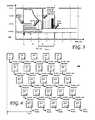
- FIG. 2is a graphical representation of a conventional array of disk drives and the time elapsed from initial spin-up to the time at which the last group of disk drives spun-up reports that they are ready to process data access commands.
- FIG. 3is a graph showing the current drawn from a disk drive configured to be incorporated into an array over time, from initiation of spin-up to the time at which the disk drive reports that it is ready to process data access commands, according to one embodiment.
- FIG. 4is a graphical representation of an array of disk drives, according to one embodiment.
- FIG. 5is a block diagram of a data storage device controller configured to couple to a plurality of data storage devices, according to one embodiment.
- FIG. 6is a flowchart of a method according to one embodiment.
- FIG. 1is a graph showing the current drawn from a disk drive over time, from initiation of spin-up to the time at which the disk drive reports that it is ready to process data access commands.
- the disk driveis commanded is to spin-up, at which point the disk drive draws about 1.44 amperes (A) from the power supply (not shown).
- Athe power supply
- This current drawis large, as the disk drive's spindle motor must overcome the inertia of the immobile disk pack, which manifests itself as a large back electro-motive force or BEMF, as seen across the spindle motor power terminals.
- BEMFback electro-motive force
- the disk driveapproaches its target spin rate (for example, 5400, 7200, 10,000 or 15,000 rpm)
- the current drawdecreases, as does the BEMF decreases, as the spindle motor need exert less torque to increase the angular velocity of the disk pack.
- the disk pack of the disk drivehas reached its target spin rate (e.g., the aforementioned (for example, 5400, 7200, 10,000 or 15,000 rpm), whereupon the disk drive performs a number of operations aimed to bring the disk drive in condition to service data access commands.
- This conditionis shown as “Drive Ready” in FIG. 1 , at time t 3 , about 3.9 seconds after the disk drive was commanded to spin-up, for an exemplary disk drive having the profile shown in FIG. 1 .
- FIG. 2is a graphical representation of a conventional array of disk drives and the time elapsed from initial spin-up to the time at which the last group of disk drives spun-up reports that they are ready to process data access commands.
- FIG. 3shows an array 200 of 25 disk drives, labeled D1-D25. Such an array 200 may form a RAID.
- the RAID controllerhaving only a predetermined number of amps from which the disk drives may draw during spin-up and during normal operation, may limit the number of disk drives that are spun-up simultaneously, in order to limit to aggregate current draw of the disk drives to within the specified limits of the RAID power supply.
- FIG. 1the example of FIG.
- the RAID controller(not shown), five disk drives are shown to be spun-up simultaneously, beginning with disk drives D1 through D5.
- the next groupi.e., disk drives D6-D10
- the next group D11-D15may be spun-up, followed by D16-D20 and ending with the last group of disk drives; namely, disk drives D21-D25.
- the time interval elapsed between the initial group of disk drives being commanded to spin-up and the last group of drives reporting “Drive Ready”is shown in FIG. 2 as t conv . While there may be some small variation across drives in the timing of the “Drive Ready” signal (assuming all drives within the array 200 are of the same type), such small variations may be safely ignored here.
- FIG. 3is a graph 300 showing the current drawn from a disk drive configured to be incorporated into an array over time, from initiation of spin-up to the time at which the disk drive reports that it is ready to process data access commands, according to one embodiment. It is to be noted that embodiments are equally applicable to hybrid disk drives; that is, to data storage devices comprising both rotating media and solid state memory. According to one embodiment, the current profile of the constituent disk drives of an array may be used to good advantage in enabling next sequential disk drive(s) to be spun-up sooner than shown in FIGS. 1 and 2 . According to one embodiment, a predetermined spin rate 302 may be established. This predetermined spin rate may be, as suggested in FIG. 3 , less than the target spin rate of the disk drive.
- this predetermined spin rate 302is reached sooner than the disk drive would otherwise reach the disk drive's target spin rate (the aforementioned 5400, 7200, 10,000 or 15,000 rpm) and sooner than the disk drive indicates its readiness to process data access commands.
- the current drawn from the disk drive when the disk drive reaches the predetermined spin rateis sufficiently low as to enable the next disk drive or disk drives to be spun-up without overloading the power supply.
- the time elapsed between t 0meaning the point in time at which the disk drive was commanded to spin-up and t Pred rpm , the time at which the predetermined spin rate has been reached, is less than from t 0 to t 3 , the point in time at which the disk drive has indicated that it is ready to process data access commands.
- the interval from t 0 to t Pred rpmis less than the time interval from t 0 to the period in time at which the disk drive has reached its target spin rate. From inspection of the embodiment of FIG.
- the predetermined spin ratemay be predetermined for each kind, type or model of disk drives. Indeed, such predetermined spin rate may be determined by the manufacturer for each disk drive kind, type or model. Alternatively, the predetermined spin rate may be predetermined for each individual disk drive. For example, such predetermined spin rate may be set by the manufacturer at the time of, for example, Initial Burn In or IBI. According to one embodiment, the predetermined spin rate may be a predetermined percentage of the target spin rate. For example, the predetermined spin rate may be selected to be between about 20% and about 90% of the target spin rate of the disk drive. According to one embodiment, the predetermined percentage may be selected to be between about 50% and about 80% of the target spin rate of the disk drive.
- the predetermined percentagemay be selected to be about 75% of the target spin rate of the disk drive. Accordingly, for a 7200 rpm disk drive and a predetermined percentage of 75%, the array controller may command the next sequential disk drive or disk drives to spin-up when the disk drive is determined to have reached a spin rate of about 5,400 rpm.
- FIG. 4is a graphical representation of an array of disk drives, according to one embodiment.
- the controllermay be configured, according to one embodiment, to command the next sequential disk drive or disk drives to spin-up as soon as (or shortly after) the disk drive(s) have reached or exceeded a predetermined spin rate.
- the arrows within the current profiles shown within the disk drives D1-D25signal the point in time at which the next sequential drive or drives of the array may be spun-up. As shown in FIG.
- the entire array 400may be considered to be ready for unrestricted reads and writes to all of its constituent disk drives when the last disk drive has indicated that it is ready to process data access commands, as noted by the “Drive Ready” legend in FIG. 4 .
- the time interval elapsed between t 0the time at which the controller commands the first disk drive or group of disk drives to spin-up and t Emb , the time at which the last disk drive or the last group of disk drives indicates that it is ready to process data access commands, may be less than the corresponding time interval t 0 to t Conv shown in FIG. 2 .
- t Embmay correspond to the point in time at which the last disk drive reports that it is ready to process data access commands.
- the disk drives of array 400may be substantially identical (i.e., same make and model)
- the disk drives shown in the last spun-up group; namely, disk drives D21 to D25may report being ready to support data access commands at substantially the same time, with minimal variations from drive to drive. Although such variations are acknowledged, they may be safely ignored herein for purposes of illustration and explanation.
- FIG. 5is a block diagram of a data storage device controller 502 configured to couple to a plurality of data storage devices, according to one embodiment.
- the controller 502may be configured to couple to a plurality 504 of disk drives.
- Such plurality of disk drives 504may be organized as an array of disk drives.
- reference 504may denote a RAID.
- the data storage device (e.g., disk drive) controller 502may be configured, according to one embodiment, to carry out the method of FIG. 6 .
- block B 61calls for the controller 502 to initiate spin-up of at least one first disk drive of the array. For example, and with reference to FIGS.
- the controller 502may command one or more disk drives of the first row (disk drives D1-D5) to spin-up. Such first disk drives may, therefore, be found in the first row of the disk drives shown in FIGS. 4 and 5 . It is to be understood that five disk drives per row is shown in FIGS. 4 and 5 for illustrative and exemplary purposes only.
- the array 504may be, for example, a RAID comprising fifty or more disk drives, which may be spatially and/or logically arranged in a manner that is different than that shown in FIGS. 4 and 5 .
- the controller 502may determine when each of the one or more first disk drives of the array for which spin-up was initiated reaches a predetermined spin rate that is less than a target spin rate at which the disk drive is ready to process data access commands.
- the controller at block B 63may initiate spin-up of one or more second disk drives.
- Such one or more second disk drivesmay comprise a single disk drive of the array 504 or may comprise, for example, an entire row (or other relevant grouping) of disk drives. For example, with reference to FIGS.
- the controller 502having determined that disk drives D1-D5 have each reached the predetermined spin rate, may command next sequential second disk drives D6-D10 to spin-up, as a group. Alternatively, as each disk drive D1-D5 reaches the predetermined spin rate, individual ones of the second disk drives D6-D10 may be spun-up in turn. If the second disk drives are not spun-up in groups of predetermined size, the controller 502 may ensure that no more than a maximum number of disk drives spins-up at any given time, to keep the aggregate current draw within the specified capacity of the power supply to source such aggregate current.
- the controller 502may be configured to poll the disk drives to determine when they have reached the predetermined spin rate.
- code controlling the disk drive spindle motormay be configured to update a status bit when the predetermined spin rate has been reached or exceeded. Such status bit may then be interrogated or polled by the controller 502 to enable the determination of when the predetermined spin rate has been reached.
- the disk drives of the array 504may be configured to set one or more page codes of one or more mode pages (e.g., for Small Computer System Interface (SCSI) drives) when the predetermined spin rate has been reached.
- SCSISmall Computer System Interface
- the controller 502may be configured to interrogate the mode page(s) to determine the set page code(s), and to interpret the obtained page codes to determine when the predetermined spin rate has been reached.
- the controller 502may be configured to determine when the disk drives have reached the predetermined spin rate by issuing an Inquiry command, in the case wherein the array 504 comprises Serial Advanced Technology Attachment (SATA) disk drives.
- SATASerial Advanced Technology Attachment
- the controller 502 and the array of disk drives 504may be configured such that the controller 502 may determine that the predetermined spin rate has been reached at least about 250 ms prior to the disk drives indicating being ready to process data access commands. According to one embodiment, the controller 502 may determine that the predetermined spin rate has been reached at least about 500 ms to at least about 2 seconds prior to the disk drives indicating being ready to process data access commands. For example, the controller 502 may determine that the predetermined spin rate has been reached at least about 1 second prior to the disk drives indicating being ready to process data access commands. Other timings are possible.
- the determination of having reached the predetermined spin ratemay be made by the controller 502 monitoring the BEMF exhibited by the disk drives during spin-up. That is, when the disk drive(s) exhibit a BEMF that has dropped to or below a threshold point corresponding to the disk drive having spun-up to the predetermined spin rate, the next sequential disk drive or drives may be commanded to spin-up.
- the firmware of the disk drives of the array 504may be configured to report to the controller 502 when the predetermined spin rate has been reached. Such reporting may take the form of, for example, setting one or more bits that, when evaluated by a polling controller 502 , are indicative of the disk drive having reached its predetermined spin rate.
- embodimentsmay take good advantage of prior knowledge of the disk drive spin-up, current or BEMF profile of disk drives to enable a greater number of disk drives to be spun-up than is conventionally possible. Alternatively, a smaller power supply may be used than would otherwise be conventionally possible.
- Parameters other than that described hereinmay be used to determine when the disk drives have reached the predetermined spin-rate. For example, analysis of the vibrations or audio signature of the drive may be indicative of the current spin rate of the disk drive.
- the predetermined spin ratemay be dynamically adjusted to ambient conditions that may affect the spin rate of the disk drive or the rate at which the disk drive platters are accelerated to reach their target spin rates.
- the “Time to First Data”may be significantly improved in RAID and other installations.
Landscapes
- Debugging And Monitoring (AREA)
- Rotational Drive Of Disk (AREA)
- Signal Processing For Digital Recording And Reproducing (AREA)
Abstract
Description
Claims (23)
Priority Applications (5)
| Application Number | Priority Date | Filing Date | Title |
|---|---|---|---|
| US13/802,337US9058835B2 (en) | 2013-03-13 | 2013-03-13 | Methods and systems for optimized staggered disk drive spinup |
| PCT/US2014/026812WO2014160487A1 (en) | 2013-03-13 | 2014-03-13 | Methods and systems for optimized staggered disk drive spinup |
| HK16105884.0AHK1217797A1 (en) | 2013-03-13 | 2014-03-13 | Methods and systems for optimized staggered disk drive spinup |
| EP14775858.5AEP2972906B1 (en) | 2013-03-13 | 2014-03-13 | Methods and systems for optimized staggered disk drive spinup |
| CN201480015535.4ACN105164655A (en) | 2013-03-13 | 2014-03-13 | Methods and systems for optimized staggered disk drive spinup |
Applications Claiming Priority (1)
| Application Number | Priority Date | Filing Date | Title |
|---|---|---|---|
| US13/802,337US9058835B2 (en) | 2013-03-13 | 2013-03-13 | Methods and systems for optimized staggered disk drive spinup |
Publications (2)
| Publication Number | Publication Date |
|---|---|
| US20140268402A1 US20140268402A1 (en) | 2014-09-18 |
| US9058835B2true US9058835B2 (en) | 2015-06-16 |
Family
ID=51526069
Family Applications (1)
| Application Number | Title | Priority Date | Filing Date |
|---|---|---|---|
| US13/802,337ActiveUS9058835B2 (en) | 2013-03-13 | 2013-03-13 | Methods and systems for optimized staggered disk drive spinup |
Country Status (5)
| Country | Link |
|---|---|
| US (1) | US9058835B2 (en) |
| EP (1) | EP2972906B1 (en) |
| CN (1) | CN105164655A (en) |
| HK (1) | HK1217797A1 (en) |
| WO (1) | WO2014160487A1 (en) |
Families Citing this family (2)
| Publication number | Priority date | Publication date | Assignee | Title |
|---|---|---|---|---|
| US9798620B2 (en)* | 2014-02-06 | 2017-10-24 | Sandisk Technologies Llc | Systems and methods for non-blocking solid-state memory |
| KR102283078B1 (en) | 2019-09-10 | 2021-07-30 | 삼성전기주식회사 | Multi-layered ceramic capacitor and method of manufacturing the same |
Citations (41)
| Publication number | Priority date | Publication date | Assignee | Title |
|---|---|---|---|---|
| US20020084760A1 (en)* | 2000-04-28 | 2002-07-04 | Messenger Carl R. | Disk drive employing method of spinning up spindle motor including detecting BEMF polarity change for selecting initial commutation state |
| US6499054B1 (en) | 1999-12-02 | 2002-12-24 | Senvid, Inc. | Control and observation of physical devices, equipment and processes by multiple users over computer networks |
| US20030115413A1 (en) | 2001-12-13 | 2003-06-19 | Seagate Technology Llc | Data storage array spin-up control |
| US20030212857A1 (en) | 2002-05-09 | 2003-11-13 | International Business Machines Corporation | Adaptive startup policy for accelerating multi-disk array spin-up |
| US20050141375A1 (en) | 2002-12-30 | 2005-06-30 | Matsushita Electric Industrial Co., Ltd. | Operating a rotatable media storage device at multiple spin-speeds |
| US20050144200A1 (en) | 1999-12-02 | 2005-06-30 | Lambertus Hesselink | Managed peer-to-peer applications, systems and methods for distributed data access and storage |
| US20050144195A1 (en) | 1999-12-02 | 2005-06-30 | Lambertus Hesselink | Managed peer-to-peer applications, systems and methods for distributed data access and storage |
| US20050195694A1 (en)* | 2004-03-03 | 2005-09-08 | Hui-Chih Lin | Method and apparatus for controlling data access rate of an optical disc driver |
| US20050289364A1 (en) | 2004-06-29 | 2005-12-29 | Intel Corporation | Method and apparatus for performing a staggered spin-up process for serial advanced technology attachment devices |
| US20060080483A1 (en)* | 2004-09-30 | 2006-04-13 | Hitachi Global Storage Technologies Netherlands B.V. | Disk device for serial communication and method of controlling the same |
| US7120692B2 (en) | 1999-12-02 | 2006-10-10 | Senvid, Inc. | Access and control system for network-enabled devices |
| US20070192639A1 (en)* | 2006-02-16 | 2007-08-16 | Lsi Logic Corporation | Apparatus and methods for power management and spin-up in a storage system |
| US7370220B1 (en) | 2003-12-26 | 2008-05-06 | Storage Technology Corporation | Method and apparatus for controlling power sequencing of a plurality of electrical/electronic devices |
| US7447926B1 (en)* | 2004-09-27 | 2008-11-04 | Emc Corporation | Disk drive input sequencing for staggered drive spin-up |
| US7454443B2 (en) | 2003-08-26 | 2008-11-18 | Tamir Ram | Method, system, and program for personal data management using content-based replication |
| US7546353B2 (en) | 1999-12-02 | 2009-06-09 | Western Digital Technologies, Inc. | Managed peer-to-peer applications, systems and methods for distributed data access and storage |
| US7587467B2 (en) | 1999-12-02 | 2009-09-08 | Western Digital Technologies, Inc. | Managed peer-to-peer applications, systems and methods for distributed data access and storage |
| US7661005B2 (en) | 2006-06-30 | 2010-02-09 | Seagate Technology Llc | Individual storage device power control in a multi-device array |
| US20110063750A1 (en) | 2009-09-15 | 2011-03-17 | Samsung Electronics Co., Ltd. | System and method to control spin-up of storage device |
| US7917628B2 (en) | 1999-12-02 | 2011-03-29 | Western Digital Technologies, Inc. | Managed peer-to-peer applications, systems and methods for distributed data access and storage |
| US7934251B2 (en) | 1999-12-02 | 2011-04-26 | Western Digital Technologies, Inc. | Managed peer-to-peer applications, systems and methods for distributed data access and storage |
| US7949564B1 (en) | 2000-05-31 | 2011-05-24 | Western Digital Technologies, Inc. | System and method of receiving advertisement content from advertisers and distributing the advertising content to a network of personal computers |
| US8004791B2 (en) | 2008-02-22 | 2011-08-23 | Western Digital Technologies, Inc. | Information storage device with a bridge controller and a plurality of electrically coupled conductive shields |
| US20120036041A1 (en) | 2010-08-09 | 2012-02-09 | Western Digital Technologies, Inc. | Methods and systems for a personal multimedia content archive |
| US8255661B2 (en) | 2009-11-13 | 2012-08-28 | Western Digital Technologies, Inc. | Data storage system comprising a mapping bridge for aligning host block size with physical block size of a data storage device |
| US8285965B2 (en) | 2009-11-20 | 2012-10-09 | Western Digital Technologies, Inc. | Aligning data storage device partition to boundary of physical data sector |
| US8296513B1 (en) | 2009-08-21 | 2012-10-23 | Pmc-Sierra, Inc. | Standby disk spin up control in disk array system using expander device |
| US8352567B2 (en) | 1999-12-02 | 2013-01-08 | Western Digital Technologies, Inc. | VCR webification |
| US20130212401A1 (en) | 2012-02-14 | 2013-08-15 | Western Digital Technologies, Inc. | Methods and devices for authentication and data encryption |
| US8526798B2 (en) | 2009-12-23 | 2013-09-03 | Western Digital Technologies, Inc. | Portable content container displaying A/V files in response to a command received from a consumer device |
| US20130268771A1 (en) | 2012-04-10 | 2013-10-10 | Western Digital Technologies, Inc. | Digital rights management system and methods for accessingcontent from an intelligent storag |
| US20130268759A1 (en) | 2012-04-10 | 2013-10-10 | Western Digital Technologies, Inc. | Digital rights management system transfer of content and distribution |
| US8631284B2 (en) | 2010-04-30 | 2014-01-14 | Western Digital Technologies, Inc. | Method for providing asynchronous event notification in systems |
| US8646054B1 (en) | 2012-03-23 | 2014-02-04 | Western Digital Technologies, Inc. | Mechanism to manage access to user data area with bridged direct-attached storage devices |
| US8688797B2 (en) | 1999-12-02 | 2014-04-01 | Western Digital Technologies, Inc. | Managed peer-to-peer applications, systems and methods for distributed data access and storage |
| US20140095439A1 (en) | 2012-10-01 | 2014-04-03 | Western Digital Technologies, Inc. | Optimizing data block size for deduplication |
| US8713265B1 (en) | 2010-09-21 | 2014-04-29 | Western Digital Technologies, Inc. | Visual indicator of online backup |
| US20140169921A1 (en) | 2012-12-19 | 2014-06-19 | Mark Carey | Cargo carrier |
| US20140173215A1 (en) | 2012-12-13 | 2014-06-19 | Western Digital Technologies, Inc. | Methods and systems for provisioning a bootable image on to an external drive |
| US8762682B1 (en) | 2010-07-02 | 2014-06-24 | Western Digital Technologies, Inc. | Data storage apparatus providing host full duplex operations using half duplex storage devices |
| US8780004B1 (en) | 2012-01-31 | 2014-07-15 | Western Digital Technologies, Inc. | Dual configuration enclosure with optional shielding |
- 2013
- 2013-03-13USUS13/802,337patent/US9058835B2/enactiveActive
- 2014
- 2014-03-13WOPCT/US2014/026812patent/WO2014160487A1/enactiveApplication Filing
- 2014-03-13EPEP14775858.5Apatent/EP2972906B1/enactiveActive
- 2014-03-13HKHK16105884.0Apatent/HK1217797A1/enunknown
- 2014-03-13CNCN201480015535.4Apatent/CN105164655A/enactivePending
Patent Citations (53)
| Publication number | Priority date | Publication date | Assignee | Title |
|---|---|---|---|---|
| US7120692B2 (en) | 1999-12-02 | 2006-10-10 | Senvid, Inc. | Access and control system for network-enabled devices |
| US8341275B1 (en) | 1999-12-02 | 2012-12-25 | Western Digital Technologies, Inc. | Access and control system for network-enabled devices |
| US7917628B2 (en) | 1999-12-02 | 2011-03-29 | Western Digital Technologies, Inc. | Managed peer-to-peer applications, systems and methods for distributed data access and storage |
| US7788404B2 (en) | 1999-12-02 | 2010-08-31 | Western Digital Technologies, Inc. | Access and control system for network-enabled devices |
| US6732158B1 (en) | 1999-12-02 | 2004-05-04 | Senvid, Inc. | VCR webification |
| US8352567B2 (en) | 1999-12-02 | 2013-01-08 | Western Digital Technologies, Inc. | VCR webification |
| US20050144200A1 (en) | 1999-12-02 | 2005-06-30 | Lambertus Hesselink | Managed peer-to-peer applications, systems and methods for distributed data access and storage |
| US20050144195A1 (en) | 1999-12-02 | 2005-06-30 | Lambertus Hesselink | Managed peer-to-peer applications, systems and methods for distributed data access and storage |
| US8793374B2 (en) | 1999-12-02 | 2014-07-29 | Western Digital Technologies, Inc. | Managed peer-to-peer applications, systems and methods for distributed data access and storage |
| US7600036B2 (en) | 1999-12-02 | 2009-10-06 | Western Digital Technologies, Inc. | Access and control system for network-enabled devices |
| US8688797B2 (en) | 1999-12-02 | 2014-04-01 | Western Digital Technologies, Inc. | Managed peer-to-peer applications, systems and methods for distributed data access and storage |
| US8661507B1 (en) | 1999-12-02 | 2014-02-25 | Western Digital Technologies, Inc. | Managed peer-to-peer applications, systems and methods for distributed data access and storage |
| US6499054B1 (en) | 1999-12-02 | 2002-12-24 | Senvid, Inc. | Control and observation of physical devices, equipment and processes by multiple users over computer networks |
| US7587467B2 (en) | 1999-12-02 | 2009-09-08 | Western Digital Technologies, Inc. | Managed peer-to-peer applications, systems and methods for distributed data access and storage |
| US7934251B2 (en) | 1999-12-02 | 2011-04-26 | Western Digital Technologies, Inc. | Managed peer-to-peer applications, systems and methods for distributed data access and storage |
| US7546353B2 (en) | 1999-12-02 | 2009-06-09 | Western Digital Technologies, Inc. | Managed peer-to-peer applications, systems and methods for distributed data access and storage |
| US7467187B2 (en) | 1999-12-02 | 2008-12-16 | Western Digital Technologies, Inc. | Control and observation of physical devices, equipment and processes by multiple users over computer networks |
| US20020084760A1 (en)* | 2000-04-28 | 2002-07-04 | Messenger Carl R. | Disk drive employing method of spinning up spindle motor including detecting BEMF polarity change for selecting initial commutation state |
| US7949564B1 (en) | 2000-05-31 | 2011-05-24 | Western Digital Technologies, Inc. | System and method of receiving advertisement content from advertisers and distributing the advertising content to a network of personal computers |
| US20030115413A1 (en) | 2001-12-13 | 2003-06-19 | Seagate Technology Llc | Data storage array spin-up control |
| US6966006B2 (en) | 2002-05-09 | 2005-11-15 | International Business Machines Corporation | Adaptive startup policy for accelerating multi-disk array spin-up |
| US20030212857A1 (en) | 2002-05-09 | 2003-11-13 | International Business Machines Corporation | Adaptive startup policy for accelerating multi-disk array spin-up |
| US20050141375A1 (en) | 2002-12-30 | 2005-06-30 | Matsushita Electric Industrial Co., Ltd. | Operating a rotatable media storage device at multiple spin-speeds |
| US7454443B2 (en) | 2003-08-26 | 2008-11-18 | Tamir Ram | Method, system, and program for personal data management using content-based replication |
| US8341117B2 (en) | 2003-08-26 | 2012-12-25 | Arkeia Software, Inc. | Method, system, and program for personal data management using content-based replication |
| US7370220B1 (en) | 2003-12-26 | 2008-05-06 | Storage Technology Corporation | Method and apparatus for controlling power sequencing of a plurality of electrical/electronic devices |
| US20050195694A1 (en)* | 2004-03-03 | 2005-09-08 | Hui-Chih Lin | Method and apparatus for controlling data access rate of an optical disc driver |
| US20050289364A1 (en) | 2004-06-29 | 2005-12-29 | Intel Corporation | Method and apparatus for performing a staggered spin-up process for serial advanced technology attachment devices |
| US7447926B1 (en)* | 2004-09-27 | 2008-11-04 | Emc Corporation | Disk drive input sequencing for staggered drive spin-up |
| US20060080483A1 (en)* | 2004-09-30 | 2006-04-13 | Hitachi Global Storage Technologies Netherlands B.V. | Disk device for serial communication and method of controlling the same |
| US20070192639A1 (en)* | 2006-02-16 | 2007-08-16 | Lsi Logic Corporation | Apparatus and methods for power management and spin-up in a storage system |
| US7661005B2 (en) | 2006-06-30 | 2010-02-09 | Seagate Technology Llc | Individual storage device power control in a multi-device array |
| US8004791B2 (en) | 2008-02-22 | 2011-08-23 | Western Digital Technologies, Inc. | Information storage device with a bridge controller and a plurality of electrically coupled conductive shields |
| US8296513B1 (en) | 2009-08-21 | 2012-10-23 | Pmc-Sierra, Inc. | Standby disk spin up control in disk array system using expander device |
| US20110063750A1 (en) | 2009-09-15 | 2011-03-17 | Samsung Electronics Co., Ltd. | System and method to control spin-up of storage device |
| US8255661B2 (en) | 2009-11-13 | 2012-08-28 | Western Digital Technologies, Inc. | Data storage system comprising a mapping bridge for aligning host block size with physical block size of a data storage device |
| US8285965B2 (en) | 2009-11-20 | 2012-10-09 | Western Digital Technologies, Inc. | Aligning data storage device partition to boundary of physical data sector |
| US8526798B2 (en) | 2009-12-23 | 2013-09-03 | Western Digital Technologies, Inc. | Portable content container displaying A/V files in response to a command received from a consumer device |
| US8631284B2 (en) | 2010-04-30 | 2014-01-14 | Western Digital Technologies, Inc. | Method for providing asynchronous event notification in systems |
| US8762682B1 (en) | 2010-07-02 | 2014-06-24 | Western Digital Technologies, Inc. | Data storage apparatus providing host full duplex operations using half duplex storage devices |
| US20120036041A1 (en) | 2010-08-09 | 2012-02-09 | Western Digital Technologies, Inc. | Methods and systems for a personal multimedia content archive |
| US8713265B1 (en) | 2010-09-21 | 2014-04-29 | Western Digital Technologies, Inc. | Visual indicator of online backup |
| US8780004B1 (en) | 2012-01-31 | 2014-07-15 | Western Digital Technologies, Inc. | Dual configuration enclosure with optional shielding |
| US20130212401A1 (en) | 2012-02-14 | 2013-08-15 | Western Digital Technologies, Inc. | Methods and devices for authentication and data encryption |
| US8819443B2 (en) | 2012-02-14 | 2014-08-26 | Western Digital Technologies, Inc. | Methods and devices for authentication and data encryption |
| US8646054B1 (en) | 2012-03-23 | 2014-02-04 | Western Digital Technologies, Inc. | Mechanism to manage access to user data area with bridged direct-attached storage devices |
| US20130268771A1 (en) | 2012-04-10 | 2013-10-10 | Western Digital Technologies, Inc. | Digital rights management system and methods for accessingcontent from an intelligent storag |
| US20130266137A1 (en) | 2012-04-10 | 2013-10-10 | Western Digital Technologies, Inc. | Digital rights managment system, devices, and methods for binding content to an intelligent storage device |
| US20130268759A1 (en) | 2012-04-10 | 2013-10-10 | Western Digital Technologies, Inc. | Digital rights management system transfer of content and distribution |
| US20130268749A1 (en) | 2012-04-10 | 2013-10-10 | Western Digital Technologies, Inc. | Digital rights management system and methods for provisioning content to an intelligent storage |
| US20140095439A1 (en) | 2012-10-01 | 2014-04-03 | Western Digital Technologies, Inc. | Optimizing data block size for deduplication |
| US20140173215A1 (en) | 2012-12-13 | 2014-06-19 | Western Digital Technologies, Inc. | Methods and systems for provisioning a bootable image on to an external drive |
| US20140169921A1 (en) | 2012-12-19 | 2014-06-19 | Mark Carey | Cargo carrier |
Non-Patent Citations (1)
| Title |
|---|
| International Search Report and Written Opinion dated Aug. 25, 2014 from related PCT Serial No. PCT/US2014/026812, 10 pages. |
Also Published As
| Publication number | Publication date |
|---|---|
| US20140268402A1 (en) | 2014-09-18 |
| HK1217797A1 (en) | 2017-01-20 |
| WO2014160487A1 (en) | 2014-10-02 |
| EP2972906A4 (en) | 2016-11-09 |
| CN105164655A (en) | 2015-12-16 |
| EP2972906B1 (en) | 2018-08-22 |
| EP2972906A1 (en) | 2016-01-20 |
Similar Documents
| Publication | Publication Date | Title |
|---|---|---|
| US8760796B1 (en) | Reducing acoustic noise in a disk drive when exiting idle mode | |
| CN105684084B (en) | Mobile data storage device with power management | |
| US8111476B2 (en) | Disk drive spin control | |
| US6789163B2 (en) | Optimizing data transfer performance through partial write command purging in a disc drive | |
| US20080209103A1 (en) | Storage device control apparatus, storage device, and data storage control method | |
| US10152994B1 (en) | Data storage device concurrently disconnecting multiple voice coil motors from spindle motor BEMF voltage during unload | |
| US20100302664A1 (en) | Disk drive data storage systems and methods using backup power source charged by spindle motor | |
| US9058835B2 (en) | Methods and systems for optimized staggered disk drive spinup | |
| JP5521926B2 (en) | Storage system, control device, and storage device | |
| JP2008204574A (en) | Storage device and control method thereof | |
| US20120011395A1 (en) | Boot method under boot sector failure in hard disk and computer device using the same | |
| EP2188807B1 (en) | Improved lubricant distribution in hard disk drives used for digital video recorders | |
| CN103268147A (en) | Hard disk power consumption management method and device | |
| JP5285756B2 (en) | Computer system having multiple operation modes and switching method thereof | |
| JP2010027105A (en) | Disk-drive device and method for error recovery thereof | |
| JP5217452B2 (en) | Information processing apparatus and system, and storage area management method and program | |
| JP2008257411A (en) | Disk control system | |
| JP4273693B2 (en) | Information recording and / or reproducing method and information recording and / or reproducing apparatus | |
| CN100559492C (en) | Optical storage device for reproducing data of optical storage medium and related method thereof | |
| CN101819542B (en) | Boot method in abnormality of hard disk boot sector and computer device using same | |
| US7992029B2 (en) | Electronic device with temporary flag for fail safe and power cycling | |
| JP2003108314A (en) | Data storage device, computer device, write data processing device and write data processing method | |
| US9257143B1 (en) | Precautionary measures for data storage device environmental conditions | |
| US8953274B1 (en) | Deceleration of spindle motor in disk drive | |
| US7352527B1 (en) | Disk drive that balances seek speed and seek acoustics |
Legal Events
| Date | Code | Title | Description |
|---|---|---|---|
| AS | Assignment | Owner name:WESTERN DIGITAL TECHNOLOGIES, INC., CALIFORNIA Free format text:ASSIGNMENT OF ASSIGNORS INTEREST;ASSIGNOR:MCCABE, TIMOTHY J;REEL/FRAME:030022/0736 Effective date:20130313 | |
| AS | Assignment | Owner name:WESTERN DIGITAL TECHNOLOGIES, INC., CALIFORNIA Free format text:ASSIGNMENT OF ASSIGNORS INTEREST;ASSIGNOR:MCCABE, TIMOTHY J.;REEL/FRAME:034260/0682 Effective date:20130313 | |
| STCF | Information on status: patent grant | Free format text:PATENTED CASE | |
| AS | Assignment | Owner name:U.S. BANK NATIONAL ASSOCIATION, AS COLLATERAL AGENT, CALIFORNIA Free format text:SECURITY AGREEMENT;ASSIGNOR:WESTERN DIGITAL TECHNOLOGIES, INC.;REEL/FRAME:038744/0281 Effective date:20160512 Owner name:JPMORGAN CHASE BANK, N.A., AS COLLATERAL AGENT, ILLINOIS Free format text:SECURITY AGREEMENT;ASSIGNOR:WESTERN DIGITAL TECHNOLOGIES, INC.;REEL/FRAME:038722/0229 Effective date:20160512 Owner name:JPMORGAN CHASE BANK, N.A., AS COLLATERAL AGENT, ILLINOIS Free format text:SECURITY AGREEMENT;ASSIGNOR:WESTERN DIGITAL TECHNOLOGIES, INC.;REEL/FRAME:038744/0481 Effective date:20160512 Owner name:JPMORGAN CHASE BANK, N.A., AS COLLATERAL AGENT, IL Free format text:SECURITY AGREEMENT;ASSIGNOR:WESTERN DIGITAL TECHNOLOGIES, INC.;REEL/FRAME:038722/0229 Effective date:20160512 Owner name:U.S. BANK NATIONAL ASSOCIATION, AS COLLATERAL AGEN Free format text:SECURITY AGREEMENT;ASSIGNOR:WESTERN DIGITAL TECHNOLOGIES, INC.;REEL/FRAME:038744/0281 Effective date:20160512 Owner name:JPMORGAN CHASE BANK, N.A., AS COLLATERAL AGENT, IL Free format text:SECURITY AGREEMENT;ASSIGNOR:WESTERN DIGITAL TECHNOLOGIES, INC.;REEL/FRAME:038744/0481 Effective date:20160512 | |
| AS | Assignment | Owner name:WESTERN DIGITAL TECHNOLOGIES, INC., CALIFORNIA Free format text:RELEASE BY SECURED PARTY;ASSIGNOR:U.S. BANK NATIONAL ASSOCIATION, AS COLLATERAL AGENT;REEL/FRAME:045501/0714 Effective date:20180227 | |
| MAFP | Maintenance fee payment | Free format text:PAYMENT OF MAINTENANCE FEE, 4TH YEAR, LARGE ENTITY (ORIGINAL EVENT CODE: M1551); ENTITY STATUS OF PATENT OWNER: LARGE ENTITY Year of fee payment:4 | |
| AS | Assignment | Owner name:WESTERN DIGITAL TECHNOLOGIES, INC., CALIFORNIA Free format text:RELEASE OF SECURITY INTEREST AT REEL 038744 FRAME 0481;ASSIGNOR:JPMORGAN CHASE BANK, N.A.;REEL/FRAME:058982/0556 Effective date:20220203 | |
| MAFP | Maintenance fee payment | Free format text:PAYMENT OF MAINTENANCE FEE, 8TH YEAR, LARGE ENTITY (ORIGINAL EVENT CODE: M1552); ENTITY STATUS OF PATENT OWNER: LARGE ENTITY Year of fee payment:8 | |
| AS | Assignment | Owner name:JPMORGAN CHASE BANK, N.A., ILLINOIS Free format text:PATENT COLLATERAL AGREEMENT - A&R LOAN AGREEMENT;ASSIGNOR:WESTERN DIGITAL TECHNOLOGIES, INC.;REEL/FRAME:064715/0001 Effective date:20230818 Owner name:JPMORGAN CHASE BANK, N.A., ILLINOIS Free format text:PATENT COLLATERAL AGREEMENT - DDTL LOAN AGREEMENT;ASSIGNOR:WESTERN DIGITAL TECHNOLOGIES, INC.;REEL/FRAME:067045/0156 Effective date:20230818 |