US9058707B2 - System and method for managing and maintaining abrasive blasting machines - Google Patents
System and method for managing and maintaining abrasive blasting machinesDownload PDFInfo
- Publication number
- US9058707B2 US9058707B2US12/707,616US70761610AUS9058707B2US 9058707 B2US9058707 B2US 9058707B2US 70761610 AUS70761610 AUS 70761610AUS 9058707 B2US9058707 B2US 9058707B2
- Authority
- US
- United States
- Prior art keywords
- abrasive blasting
- data
- blasting machine
- operator
- user
- Prior art date
- Legal status (The legal status is an assumption and is not a legal conclusion. Google has not performed a legal analysis and makes no representation as to the accuracy of the status listed.)
- Active, expires
Links
Images


Classifications
- B—PERFORMING OPERATIONS; TRANSPORTING
- B24—GRINDING; POLISHING
- B24C—ABRASIVE OR RELATED BLASTING WITH PARTICULATE MATERIAL
- B24C7/00—Equipment for feeding abrasive material; Controlling the flowability, constitution, or other physical characteristics of abrasive blasts
- G—PHYSICS
- G07—CHECKING-DEVICES
- G07C—TIME OR ATTENDANCE REGISTERS; REGISTERING OR INDICATING THE WORKING OF MACHINES; GENERATING RANDOM NUMBERS; VOTING OR LOTTERY APPARATUS; ARRANGEMENTS, SYSTEMS OR APPARATUS FOR CHECKING NOT PROVIDED FOR ELSEWHERE
- G07C1/00—Registering, indicating or recording the time of events or elapsed time, e.g. time-recorders for work people
- G07C1/10—Registering, indicating or recording the time of events or elapsed time, e.g. time-recorders for work people together with the recording, indicating or registering of other data, e.g. of signs of identity
- B—PERFORMING OPERATIONS; TRANSPORTING
- B24—GRINDING; POLISHING
- B24C—ABRASIVE OR RELATED BLASTING WITH PARTICULATE MATERIAL
- B24C9/00—Appurtenances of abrasive blasting machines or devices, e.g. working chambers, arrangements for handling used abrasive material
- G—PHYSICS
- G05—CONTROLLING; REGULATING
- G05B—CONTROL OR REGULATING SYSTEMS IN GENERAL; FUNCTIONAL ELEMENTS OF SUCH SYSTEMS; MONITORING OR TESTING ARRANGEMENTS FOR SUCH SYSTEMS OR ELEMENTS
- G05B15/00—Systems controlled by a computer
- G05B15/02—Systems controlled by a computer electric
- G—PHYSICS
- G06—COMPUTING OR CALCULATING; COUNTING
- G06Q—INFORMATION AND COMMUNICATION TECHNOLOGY [ICT] SPECIALLY ADAPTED FOR ADMINISTRATIVE, COMMERCIAL, FINANCIAL, MANAGERIAL OR SUPERVISORY PURPOSES; SYSTEMS OR METHODS SPECIALLY ADAPTED FOR ADMINISTRATIVE, COMMERCIAL, FINANCIAL, MANAGERIAL OR SUPERVISORY PURPOSES, NOT OTHERWISE PROVIDED FOR
- G06Q10/00—Administration; Management
- G06Q10/20—Administration of product repair or maintenance
- G—PHYSICS
- G06—COMPUTING OR CALCULATING; COUNTING
- G06Q—INFORMATION AND COMMUNICATION TECHNOLOGY [ICT] SPECIALLY ADAPTED FOR ADMINISTRATIVE, COMMERCIAL, FINANCIAL, MANAGERIAL OR SUPERVISORY PURPOSES; SYSTEMS OR METHODS SPECIALLY ADAPTED FOR ADMINISTRATIVE, COMMERCIAL, FINANCIAL, MANAGERIAL OR SUPERVISORY PURPOSES, NOT OTHERWISE PROVIDED FOR
- G06Q50/00—Information and communication technology [ICT] specially adapted for implementation of business processes of specific business sectors, e.g. utilities or tourism
- G06Q50/08—Construction
Definitions
- Abrasive blastinguses a variety of blast media, including sand, coal slag, garnet, steel grit, and other blast media, and is the most common method of removing corrosion and coatings from steel and concrete surfaces.
- blast media under pressureis mixed with air in a metering valve directly under a blast pot or pressure vessel on an abrasive blasting machine.
- abrasive blasting processesinvented in the early 1900s, for use in preparing surfaces for protective coatings have always been relatively expensive based on a need for large volumes of high pressure compressed air at up to 200 psi.
- Equipment used to generate such pressuresinclude the use of a stationary or mobile compressor (e.g., electric or diesel).
- Supporting the abrasive blasting processincludes the use of blasting media, such as sand, steel grit, or other blast media to mix with the air, and labor to manage and operate nozzles used to control the blast media being directed onto the structures.
- Abrasive blasting work to prepare surfaces for coatingcan be accomplished in a fixed facility, such as a blast room, where structural components to be treated are brought for the abrasive blasting process to be completed.
- a fixed facilitysuch as a blast room
- Such fixed location processesare common where abrasive blasting is part of a manufacturing process that takes place before or after welding, but always before application of protective coatings.
- mobile operationswhere blasting equipment is moved to a structure needing abrasive blasting, such as is the case with preparation prior to coating of bridges, tanks, and ships, everything, including the blasting equipment and blast media, must be moved to the structure where the work is to take place.
- the abrasive blasting equipmentFor storage tanks, the abrasive blasting equipment is moved to the location of the storage tank, be it water or petroleum, where the abrasive blasting work is to be done to the interior and/or exterior of the storage tank, as required. In shipyard work, the abrasive blasting equipment may be used in a dry dock, outside the dry dock, or placed some distance from the surfaces being cleaned. On a typical ship, the surface area of the internal ballast and fuel tanks is often 17 times as great as the actual surface of the hull of the vessel.
- Abrasive blasting machines in their current mobile and fixed configurationshave been available for approximately 35 years. Throughout this period, abrasive blasting machines have been configured using rudimentary equipment (e.g., blowers, compressors, mixers, valves). Owners (e.g., construction companies) of abrasive blasting machines have had little actual machine operational data to use in managing the abrasive blasting machines. The owners/operators generally have a supervisor and crew that operate the abrasive blasting machine while on a job site.
- rudimentary equipmente.g., blowers, compressors, mixers, valves.
- Operational datahas been primarily empirically collected after the fact using a macroscopic view (e.g., approximately two days to complete a 450 square foot section of a steel bridge structure), and detailed operational data that would provide an owner with more insight as to the efficiency of the supervisor, crew, and abrasive blasting machine has not been available due to the equipment being so rudimentary.
- abrasive blasting equipmentWith regard to maintenance of abrasion blasting equipment, as those skilled in the art of abrasive blasting can testify, owners and operators of abrasive blasting equipment do little by way of preventative maintenance and tend to operate on a “run it until it breaks” mode.
- Each piece of abrasive blasting equipmentis composed of thousands of parts, including electrical, mechanical, and electromechanical components.
- a technicianWhen one of the components fails, a technician is brought in to fix the problem. Often, components have certain lead times (e.g., three days) before the component can be obtained and installed by the technician. Such downtime is expensive due to the crew not producing and contract dates slipping.
- equipment failuremay lead to inefficient operation of the abrasive blasting machine or the appearance of inefficient operation. Either way, the manufacturer of the machine has the potential to lose future business, the owner/operator has the potential to lose customers, and the end customer has the potential to lose money—a bad situation for all involved.
- intelligencemay be added to abrasive blasting equipment.
- Intelligencemay be added to abrasive blasting equipment through the use of sensors and computers and provide for monitoring, collecting, processing, and presenting operational data produced by an abrasive blasting equipment. Such data may enable owners/operators and end customers to have significantly more information than previously available and improve efficiency in the industry.
- Two fundamental areasare addressed by using the principles of the present invention, including (i) management, which may include both (a) management by the owner/operator of the abrasive blasting machines and (b) management of structure projects by end customers (e.g., municipalities, oil companies, U.S. Navy), and (ii) maintenance of abrasive blasting machines, which may result in less downtime of the machines.
- an abrasive blasting systemmay include a blower configured to blow air to create an airflow.
- a metering valvemay be configured to mix blast media into the airflow.
- a controllermay be in communication with said blower and the metering valve.
- a blasting hosein fluid communication with the blower.
- a nozzlemay be connected to an end of said blasting hose.
- a control switchmay be connected to the nozzle and be configured to enable an operator to (i) selectively cause the controller to cause the airflow created by the blower to pass through the blasting hose and nozzle in response to the control switch being in a first state, and (ii) selectively cause the metering valve to mix the blast media with the airflow for passing the blast media through the blasting hose and nozzle in response to the control switch being in a second state.
- a timermay be in communication with the controller and be configured to time duration that the metering valve is being operated to mix the blasting media with the airflow to enable the operator to perform abrasive blasting.
- a user interfacemay be in communication with the controller to enable a user to display the duration that the operator is performing abrasive blasting.
- One embodiment of a method for managing abrasive blastingmay include timing duration of blast media being blown in performing abrasive blasting using an abrasive blasting machine. Time duration that an operator worked in association with the duration of the blast media being blown may be received. A blasting efficiency ratio may be computed based on the duration of the blasting media being blown and duration of that the operator worked. The blasting efficiency ratio may be displayed to a user.
- One method for managing a fleet of abrasive blasting machinesmay include collecting operational data produced by a plurality of abrasive blasting machines at a remote computing system from the abrasive blasting machines.
- the collected operational datamay be stored in a data repository. At least a portion of the collected operational data may be displayed for a user to view.
- One embodiment of a method for maintaining an abrasive blasting machinemay include establishing, in an electronic memory, a set of preventative maintenance parameters associated with a respective set of components of the abrasive blasting machine. Sensors that collect operational data of components of the abrasive blasting machine that correlate to the set of preventative maintenance parameters may be monitored. A determination that operational data of a component has crossed a preventative maintenance parameter may be made. In response to determining that the operational data of the component crossed a preventative maintenance parameter, a user may be notified to perform preventative maintenance on the component of the abrasive blasting machine.
- a signaling system reportermay be configured to receive the preset message associated with abrasive blasting and display the preset message for another operator.
- the signaling system reportermay be configured as part of an abrasive blasting machine or be separate from the machine.
- the transceivermay be attached to a nozzle of a blast hose or be separate therefrom.
- One embodiment of a method for providing communications between workers of an abrasive blasting machine on a jobsitemay include communicating a preset message related to abrasive blasting operations to another device in response to an operator selecting to send the preset message, and displaying the preset message for another operator to view.
- FIG. 1is an isometric view of an illustrative mobile abrasive blasting machine that includes a controller for use in monitoring, collecting, and processing sensor data measured from components of the abrasive blasting machine;
- FIG. 2is a block diagram of an illustrative electrical system that includes a controller configured to receive control and sensor data and generating control information to control components of the abrasive blasting machine;
- FIG. 3is an illustration of an illustrative network environment in which an abrasive blasting machine communicates blasting data to a remote server located on a network;
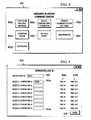
- FIG. 4is a screenshot of an illustrative graphical user interface (GUI) that enables a user to manage and maintain an abrasive blasting machine;
- GUIgraphical user interface
- FIG. 5is a screenshot of an illustrative GUI that enables operators of an abrasive blasting machine to enter operator IDs when operating the abrasive blasting machine;
- FIG. 6is a screenshot of an illustrative GUI that enables a supervisor or other user to enter daily status information to provide for better tracking of operation of an abrasive blasting machine;
- FIG. 7is a screenshot of a GUI with an illustrative list of parameters that may be selectably tracked by a computing unit of an abrasive blasting machine;
- FIG. 8is a screenshot of an illustrative GUI that provides a “dashboard” showing parameters being collected on an abrasive blasting machine
- FIG. 9is a screenshot of an illustrative GUI that enables a maintenance technician or other user to view current maintenance status and usage of components of an abrasive blasting machine;
- FIG. 10is a block diagram of an illustrative server that may be located on a communications network that is configured to receive operational data from one or more abrasive blasting machines;
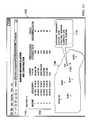
- FIG. 11is a screenshot of an illustrative GUI that may be viewed by a manager of one or more abrasive blasting machines to provide current status and management information;
- FIG. 12is a screenshot of an illustrative GUI that may be utilized by a manager of an end customer of an owner/operator of an abrasive blasting machine for use in monitoring jobs and activities by the abrasive blasting machines being performed at those jobs;
- FIG. 13is a screenshot of an illustrative GUI that provides for preventative maintenance information of abrasive blasting machines and a maintenance log of maintenance performed on components of the abrasive blasting machines;
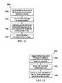
- FIG. 14is a flow diagram of an illustrative process that enables an owner/operator to view operational data collected from a processing unit on an abrasive blasting machine and processed for display to the user;
- FIG. 15is a flow diagram of an illustrative process that enables operational data produced by multiple abrasive blasting machines for display to a user for comparison purposes;
- FIG. 16is a flow diagram of an illustrative process that enables an owner/operator to efficiently perform preventative maintenance as a result of operational data being collected by an abrasive blasting machine;
- FIG. 17is an illustration of an illustrative communications system for use on a jobsite that enables equipment operators and other workers (e.g., supervisors) to communicate with one another while far away or in noisy environments; and
- FIG. 18is a flow chart of an illustrative process for providing communications between workers on a jobsite.
- FIG. 1an illustration of an illustrative abrasive blasting machine 100 is shown.
- the abrasive blasting machine 100 in this configurationis mobile in that it resides on a trailer 102 that enables the abrasive blasting machine 100 to be transported from job site to job site for performing abrasive blasting on a structure (e.g., bridge) at the job site.
- the abrasive blasting machine 100includes a compressor manifold 104 that enables multiple compressors to feed into the manifold 104 for use in blowing blast media by the abrasive blasting machine 100 .
- An engine 106which may be a diesel engine or other powered engine, for use in producing vacuum power and generating hydraulic power for driving various components on the abrasive blasting machine 100 .
- a vacuum 108may be utilized to enable an operator of the abrasive blasting machine 100 to vacuum blast media after the blast media is projected onto surfaces of a structure being prepared for a protective coating to be applied thereto.
- An air wash 110may be utilized to cleanse dust that is collected by the vacuum 108 .
- a pre-classifier 112may be utilized to sort out debris or other material that is collected by the vacuum and greater than a certain size, such as three-sixteenths of an inch.
- a classifier 114such as a magnetic drum, may be configured to sort or otherwise separate the blast media, such as steel grit, from other debris, such as paint chips, that are collected by the vacuum process.
- a storage hopper 116may be utilized to store blast media that is utilized for performing the abrasive blasting by the abrasive blasting machine 100 .
- a pressure vessel 118may be utilized to generate a pressure for the blast media in being introduced into airflow created by a compressor.
- the pressure vessel 118is in fluid communication with metering valves 120 that are selectively open and shut for introducing the blast media into airflow produced by the compressor for use in blowing the blast media onto surfaces of a structure being prepared for a protective coating to be applied thereto.
- airflow without blast mediamay be created and used by an operator of a blast hose (not shown) that includes a nozzle (not shown).
- Blast mediamay be selectively added to the airflow and directed onto surfaces of a structure.
- the nozzle of a blast hosemay include a “dead-man” switch (not shown) that, when in a first position, causes compressed airflow to be pushed through the blast hose and nozzle, and, when in a second position, causes both airflow and blast media to be pushed through the blast hose and nozzle.
- the dead-man switchmay be in communication with a controller 122 and/or other valve control circuitry (not shown) that causes the airflow and/or blast media to be blown through the blast hose and nozzle.
- Alternative control switchesmay be utilized in accordance with the principles of the present invention.
- the controller 122may be part of the abrasive blasting machine 100 and used to control components of the abrasive blasting machine 100 .
- the controller 122may further be configured to collect and process sensor data from sensors that are applied to sense operation of various components of the abrasive blasting machine 100 .
- the controller 122which is fundamentally a processing unit that performs control and data collection functionality, may be composed of one or more computer processors and other circuitry.
- the controllermay be utilized in a manner that generates “intelligence” for owners/operators and customers of the owners/operators of the abrasive blasting machine. As described further herein, the information and statistics that may be collected and generated have heretofore not been available to owners/operators and end customers of abrasive blasting machines.
- FIG. 2a block diagram of an illustrative electrical system 200 that includes a controller 202 is shown.
- the controller 202may include one or more computer processors 204 that are configured to execute software 206 .
- the software 206may be configured to provide both control and data collection functionality in accordance with the principles of the present invention. Furthermore, the software 206 may be configured to generate statistics and other operational and maintenance information, as further provided herein.
- the processing unit 204may be in communication with a (i) memory 208 that may be configured to store data, such as clock times produced by timers that are utilized to determine how long certain operations of the abrasive blasting machine have been operating, (ii) global positioning system 210 that may be configured to collect global positioning information of the abrasive blasting machine, (iii) input/output unit 212 that may be configured to provide for both local communications on the abrasive blasting machine and remote communications with a communications network, such as a mobile telephone network or satellite communications network.
- a communications networksuch as a mobile telephone network or satellite communications network.
- the processing unit 204may further be in communication with a (iv) user interface unit 214 that may include a keyboard, pointing device (e.g., computer mouse or touchpad for controlling a cursor on an electronic display), and (v) electronic display 216 , which may be a traditional electronic display, such as an LCD display, or touch screen display that enables a user to control and interact with data being displayed on the electronic display 216 .
- a GPS systemis shown, alternative geographic location determination techniques may be utilized, such as triangulation using mobile telephone signal techniques, as understood in the art.
- a blast control switch 218such as a “dead-man” switch, which may be operated by a blast hose operator and be configured in one or multiple position to enable the blast hose operator to direct compressed air or compressed air with blast media, may be positioned on a nozzle.
- the control switch 218is a single pole, double throw switch, as understood in the art. The blast control switch 218 , if not being actively forced to a position, will automatically be forced back to a neutral position, which causes both air and blast media to be prevented from being blown through the blast hose and nozzle, as understood in the art.
- the blast control switch 218may generate a position data signal 220 , which may be in the form of an electrical signal (e.g., +/ ⁇ 5V) or data signal (e.g., data bits representing a position at which the blast control switch 218 is positioned).
- the position data signal 220may be communicated to the controller 202 for allowing the controller 202 to communicate a control signal to one or more valves for allowing airflow through the blast hose and nozzle and metering valve (not shown) that mixes blast media in the airflow.
- the controller 202may further be configured to initiate a timer to record an amount of time that the airflow and/or blast media is being used by an operator of the blast hose.
- the position data signal 220 from the blast control switch 218may be communicated directly to an electronic circuit that controls one or more valves that enables the airflow and blast media to be passed through the blast hose.
- the controller 202may receive a communications signal from the electronic circuit for controlling the valves to indicate that the operator of the blast hose is using air and/or blast media.
- the controller 202may initiate timers, one for the air and one for the blast media, which are independent of one another, for use in monitoring the length of time that air and blast media are respectively being used.
- both a daily and a lifetime timermay be used for each of the components, thereby enabling the controller 202 to effectively determine daily and lifetime usage of the compressor, blast hose, blast nozzle, and any other component that may have a limited lifetime and require preventative maintenance to replace and/or repair the components to maximize usage of the abrasive blasting machine without downtime.
- Sensors 222 a - 222 nmay be applied to components of the abrasive blasting machine that a manufacturer, owner, or operator of the abrasive blasting machine may desire to monitor in generating statistical information, maintenance information, operational information, or other information, as provided herein.
- the sensorsmay be applied to the engine, blower, metering valve, conveyor, or any other component (e.g., compressor) of the abrasive blasting machine.
- the sensors 222may communicate sensor data 224 a - 224 n , respectively, to the controller 202 for collection, storage, processing, and/or communication.
- the controller 202may further be in communication with a number of controllers 226 a - 226 n , such as a compressor valve controller and a metering valve controller.
- the controllers 226 a - 226 nmay be in communication and controlled by the controller 202 .
- the controllers 226 a - 226 nmay communicate operational data, such as valve open and valve closed data signals, to acknowledge or notify the controller 202 of operation of the valves.
- status data 228 a - 228 n(collectively 228 ) may be communicated to the controller 202 from the controllers 226 a - 226 n , respectively.
- a conventional communications busmay be utilized to provide communications between the controllers 202 , dead-man switch 218 , sensors 222 , controllers 226 , etc.
- FIG. 3is an illustration of an illustrative network 300 that includes an abrasive blasting machine 302 that includes a controller 304 that is configured to communicate with a server 306 that is remotely located from the abrasive blasting machine 302 via a communications network 308 .
- the communications network 308may be a mobile telephone network, satellite communications network, or any other communications network, as understood in the art.
- the controller 304may be configured to communicate blasting data 310 , which may include operational data, maintenance data, current status data, or any other data that may be utilized by an owner, operator, or end customer of the abrasive blasting machine 302 .
- the blasting data 310may be communicated via a communications channel 312 a between the abrasive blasting machine 302 and communications network 308 , and via a communications channel 312 b via the communications network 308 and server 306 .
- the communications channel 312 amay be a wireless communications channel as the abrasive blasting machine 302 is mobile and may be routinely moved from job site to job site. If the abrasive blasting machine 302 is stationary and can be connected via a wired connection, then the communications channel 312 a may be a wired communications channel to the communications network 308 , such as the Internet.
- the communications channel 312 bmay be wireless or wired, as understood in the art.
- the server 306may be configured to receive and/or communicate with one or more abrasive blasting machines that are being operated by one or more different operators.
- the server 306may be configured to receive, store, process, and display data collected by the abrasive blasting machine 302 via the network 308 or at a local communications network (not shown) to the server 306 .
- blasting data 314which may be the same or a derivative of blasting data 310 , may be communicated via a communications channel 316 to a mobile device 318 for processing and/or displaying thereon.
- the mobile device 318may be a mobile telephone, smart personal digital assistant (PDA), portable computer, tablet, or any other computing device, as understood in the art.
- PDApersonal digital assistant
- the mobile device 318may execute an application that enables a user 320 to interface with the data, such as selecting different parameters to view that are indicative of current or historical operation of the abrasive blasting machine 302 .
- the communications channel 316may be a communications channel between the network 308 and mobile device 318 .
- the communications channel 316may be communicated directly from the controller 304 to the mobile communications device 318 using WiFi®, Bluetooth®, or in any other local communications protocol, as understood in the art.
- the GUI 400may include a number of selectable soft-buttons 402 a - 402 g (collectively 402 ).
- the soft-buttons 402may be used in the event that an abrasive blasting machine includes a touch-screen for interfacing with a controller of the abrasive blasting machine or that the abrasive blasting machine includes a pointing device, such as a computer mouse, that enables a user to control a cursor to enable a user to select one of the soft-buttons 402 .
- the GUI 400may utilize alternative user interface elements, as understood in the art.
- a “configure machine settings” soft-button 402 amay enable a user to selectively configure settings for operation, control, and data collection from sensors of the abrasive blasting machine.
- the machine settingsmay include vacuum pressure, blower pressure, conveyor speed, blast media mixing rates, or any other component operation that may be variably set, as understood in the art.
- the settingsmay also include sensor reading rates (e.g., readings per second, readings per hour, readings per day), event triggers that cause data to be communicated to the controller (e.g., dead-man switch toggle), or any other settings, as understood in the art.
- These settingsmay also include the ability to set times or events that cause the controller of the abrasive blasting machine to communicate data via a communications network to a remote server.
- the settingsmay include notifying or communicating status data to the remote server in response to the machine turning on, blasting being initiated or turned off, or any other status update, as understood in the art.
- the settingsmay enable for data to be stored at the controller throughout an entire day and communicated daily or when the controller is able to communicate with a communications network, as understood in the art, since the abrasive blasting machine may be positioned in a location (e.g., within a tunnel) that the controller is unable to have communication with the communications network.
- An “operator log in” soft-button 402 bmay enable a user to log into the controller to capture operator numbers and times that the operator logs in or logs out of the controller. In effect, capturing operator login and logout times may provide a tool for tracking when an operator arrives and leaves a job site.
- the usermay be presented an operator log in GUI, such as that shown in FIG. 5 .
- a “select parameters to monitor” soft-button 402 cmay enable a user to select what parameters of the abrasive blasting machine to monitor.
- the available parametersmay be provided on a screen (see FIG. 7 ) to enable the user to select available parameters through the use of sensors and a controller included on the abrasive blasting machine.
- a “job data entry” soft-button 402 dmay enable a user to enter job information prior to and/or after work being performed on a job site each day.
- a GUIsuch as that shown in FIG. 6 , may be presented to the user to select or otherwise enter data associated with the job being performed by the abrasive blasting machine.
- a “remote communications settings” soft-button 402 emay enable the user to select remote communications operations by the controller of the abrasive blasting machine with a remote server or other remote communications device, such a mobile communications device being used local to the abrasive blasting machine.
- the remote communicationsmay include setting up scheduled times or events that trigger the controller to communicate data collected during a workday to communicate to the remote server.
- the remote communications settingsmay also enable for communicating current status, maintenance operations, and any other information collected from or generated by the controller of the abrasive blasting machine.
- a “maintenance” soft-button 402 fenables the user to actively interface with a maintenance graphical user interface (see FIG. 9 ) for viewing current maintenance status (e.g., number of hours currently used of one or more components of the abrasive blasting machine versus total number of hours available of use on each of the respective components of the abrasive blasting machine).
- the maintenance soft-button 402 fis made available only to technicians of the abrasive blasting machine by requiring the technician to enter a password prior to viewing a maintenance GUI (e.g., FIG. 9 ).
- a “dashboard” soft-button 402 genables a user to actively view operational data on a GUI (see FIG. 8 ) to view one or more operating parameters being collected by sensors and stored and processed by the controller of the abrasive blasting machine. It should be understood that one or more “dashboard” soft-buttons may be available for enabling a user to selectively view different types of operational parameters that are being collected by or generated by the controller.
- FIG. 5a screenshot of an illustrative GUI 500 that enables an operator to enter his or her employee ID or other identifier may be provided.
- a supervisormay enter his or her ID in text entry field 502 and nozzle operators may enter their operator IDs in text entry fields 504 a - 504 h (collectively 504 ).
- Vacuum operators, technicians, or any other operator that interfaces with the abrasive blasting machinemay be enabled to enter his or her employee ID or operator ID, as well.
- the operatorsmay alternatively be enabled to use a barcode scanner, magnetic strip scanner, radio frequency identifier transceiver, or any other technique for capturing an identifier associated with an operator of the abrasive blasting machine.
- the use of an RFID transceivermay track that operators are within a certain vicinity of the abrasive blasting machine (e.g., within 300 feet). Because jobsites can be larger than local wireless communications ranges, remote RFID transceivers and repeaters may be set up on the jobsite so that RFID tags or other communications devices of operators or workers may be sensed and reported to the controller.
- the GUI 500may also be configured with “time in” and “time out” selectable fields 506 a and 506 b , respectively, that enables the controller on the abrasive blasting machine to operate as an electronic punch card to allow the owner/operator to determine when operators of the abrasive blasting machine arrive and leave from a job site or take lunch breaks, etc. If a user has finished entering his or her log in, then the user may select a “back” soft-button 508 to return to the GUI 400 of FIG. 4 . It should be understood that the operator log in GUI 500 may have alternative configurations that enable users to selectively enter or select from a menu his or her user ID.
- a screenshot of an illustrative GUI 600 for a user to enter job datais shown.
- the useris a supervisor of an abrasive blasting machine at a job site who enters job entry data before and/or after a day on the job site.
- the job entry data that may be enteredmay include a job number into text entry field 602 , structure type in text entry field 604 , daily completion log in square-feet or other metric in text entry field 606 , current structure component in text entry field 608 , and weather conditions in text entry field 610 .
- the supervisormay enter shift lengths for each of the operators by selecting an operator ID in text entry field 612 and shift length in text entry field 614 .
- each of the text entry fieldsmay have a pull-down menu that may be filled in a data repository at the controller by a user of the controller or remotely from a remote server. If the user is satisfied with entries made in the job data entry GUI 600 , the user may select a “submit” soft-button 616 . Once complete, the user may select a “back” soft-button 618 for returning to a previous menu, such as GUI 400 of FIG. 4 . It should be understood that alternative configurations of the GUI 600 may be utilized, such as automatically listing all of the operators who entered their presence at the job site in FIG. 5 and providing for entry of respective shift times.
- GUI 700may include a section 702 with a list of selectable parameters 704 .
- a list of available parameters 704are listed with selectable graphical user elements 706 and 708 that allow the user to selectively monitor and/or display a virtual gauge of the parameter.
- the userhas selected to both monitor and show a virtual gauge for blower pressure, engine RPM, metering valve, and conveyor speed, but not show a gauge for compressor pressure or blast media batches.
- the virtual gauges and monitor listingsare illustratively shown in FIG. 8 .
- the GUI 700may also include a section 710 that includes a list of times 712 that may be monitored and/or gauged in a dashboard screen.
- the timessuch as engine time, blasting time, vacuum time, blower time, etc., may be generated by hardware or software timers. If hardware timers are used, the timers sense activation and deactivation of an electronic circuit that engages a component of the abrasive blasting machine. If software timers are used, then the controller of the abrasive blasting machine receives a signal indicating start and stop times of components of the abrasive blasting machine.
- the timersmay include lifetime timers of each component (i.e., from the installation of the component until the replacement of the component) and daily timers of the component, thereby enabling (i) a maintenance technician to know how much time each component has in its lifetime and (ii) management personnel to identify how much time each component is being used on a daily basis.
- the GUI 700is illustrative and that alternative configurations of the GUI 700 may be utilized in accordance with the principles of the present invention. Still yet, rather than using a GUI to interface with the controller, hardware switches (e.g., dip switches) may be utilized to cause the controller to monitor and display parameters being collected from the abrasive blasting machine. Once complete, the user may select a “back” soft-button 714 to return to the GUI 400 of FIG. 4 .
- TABLE Iis an illustrative list of parameters that may additionally be available for collection by the controller of the abrasive blasting machine and/or remote server.
- FIG. 8a screenshot of an illustrative abrasive blasting “dashboard” GUI 800 is shown.
- the GUI 800may include a blower virtual gauge 802 , metering valve virtual gauge 804 , conveyor speed virtual gauge 806 , and engine speed virtual gauge 810 .
- engine time 812 and blasting time 814 clocksmay be shown.
- the various virtual gauges 802 - 810are illustrative and other forms of virtual gauges and other parameters of components of the abrasive blasting machine may be shown through use of selection elements 708 of FIG. 7 . Alternatively, certain parameters may be fixedly shown while others may be selected to be shown (i.e., a hybrid custom dashboard).
- a “daily reset” soft-button 820may be made available for a user, such as a supervisor, to select to reset the gauges on a daily basis after the parameter data is stored by a controller of the abrasive blasting machine. The user may select a “back” soft-button 822 to return to GUI 400 of FIG. 4 .
- FIG. 9shows a maintenance GUI 900 that allows a maintenance technician, who may enter his or her ID into a text entry field 902 , to view a listing 904 of maintenance parameters.
- the maintenance parametersmay include components that are typically scheduled for preventative maintenance based on a suggested or recommended number of hours or uses by a manufacturer. For example, a blower generally has 1,000 hours of time that it may be used before replacement is suggested by the blower manufacturer. Therefore, the controller may monitor the number of hours that the blower has been utilized and display the current number of lifetime hours and the maximum number of hours.
- a maintenance technicianmay monitor when to schedule replacement of the blower.
- a “replaced” date that the blower was replaced lastmay be listed.
- a projected replacement date(not shown) may be calculated based on historical usage of the abrasive blasting machine and displayed.
- the maintenance technicianmay select a “machine maintenance mode” soft-button 906 that enables the machine to be placed in a maintenance mode, which may turn the machine off or put the machine into a particular state that allows the maintenance technician to replace or otherwise adjust a component of the abrasive blasting machine.
- maintenance timemay be displayed in a clock format in data field 908 to show the maintenance technician and/or supervisor how much time it has taken for the maintenance technician to repair the abrasive blasting machine.
- the maintenance technicianmay actively reset a current hours timer and date that the blower was replaced so that he or she and other personnel may be notified as to replacement of the blower for future planning purposes.
- the usermay select a “back” soft-button 910 to return to the GUI 400 of FIG. 4 .
- the server 1000may be remotely located from one or more abrasive blasting machines and used to collect data from each of the abrasive blasting machines for storage and processing of the data.
- the server 1000may include a processing unit 1002 composed of one or more computer processors that execute software 1004 .
- the software 1004may be configured to receive, process, and display data collected from the abrasive blasting machines.
- a memory 1006may be configured to store data during processing and software for execution on the processing unit 1002 .
- the processing unitmay be in communication with the memory 1006 , input/output unit 1008 , which may be configured to communicate data over one or more communications networks using any communications protocol, as understood in the art, and storage unit 1010 .
- the storage unit 1010may be configured to store one or more data repositories 1012 a - 1012 n (collectively 1012 ).
- the data repositoriesmay be configured to store data received from abrasive blasting machines.
- the data repositories 1012may be configured to store data that is generated by the software 1004 in response to receiving operational and/or maintenance data from the abrasive blasting machines.
- the processing unit 1002may be configured to communicate data stored in the data repositories 1012 via the I/O unit 1008 via a communications network (e.g., Internet, mobile communications network) to webpages or mobile devices, in accordance with the principles of the present invention.
- a communications networke.g., Internet, mobile communications network
- the server 1000may allow for a user to “pull” data from the controllers of the abrasive blasting machines either automatically or manually.
- FIG. 11a screenshot of an illustrative GUI 1100 that may be displayed on a webpage or mobile device is shown.
- the GUI 1100may be provided for an owner or operator of an abrasive blasting machine to view operational data.
- a number of machines that are being trackedmay be shown in a data field 1102 and each of the machines may be listed in a table 1104 .
- the table 1104may include machine number or identifier, global positioning system (GPS) coordinates, current status of each of the abrasive blasting machines, today's blasting efficiency ratio, and today's performance rating.
- the blasting efficiency ratiomay be a ratio of total time during the day that blasting is being performed versus total time that operators are at a job site (i.e., shift time). Alternative parameters may be utilized in generating a blasting efficiency ratio.
- the performance ratingmay be based on a number of different factors, including blasting efficiency ratio, on-time percentage, blowing time percentage, square feet percentage of 1000 square feet, maintenance time percentage, dead-time percentage, weather conditions, temperature conditions, and so on.
- a performance ratingmay be computed by adding blasting efficiency percentage with blowing time percentage, subtracting maintenance time percentage, adding square feet percentage, and multiplying a scale factor based on weather conditions and temperature conditions.
- the performance ratingmay be computed over a certain time duration (e.g., daily) to enable an operator or end customer to track performance by using a performance rating, each abrasive blasting machine performance may be normalized against one another.
- the performance ratingmay be an industry standard or be particular to an owner or operator of the abrasive blasting machine.
- a map 1106may be displayed in a graphical format that shows where each of the respective abrasive blasting machines are located, their current status, and, in response to a user moving a cursor 1108 over the location of one of the abrasive blasting machines, a pop-up display 1110 may show specific details associated with the abrasive blasting machine. The details may include supervisor name, current location, structure being worked on, percentage complete, status, and any other data, as provided herein. It should be understood that the GUI 1100 may have an alternative configuration and provide the same or similar functionality as described herein.
- a screenshot of an illustrative GUI 1200may be shown to enable an end customer, such as a municipality (e.g., State of New Jersey), to monitor current job sites that are being worked on by abrasive blasting machines.
- a number of job sitesmay be listed in a data field 1202 and a table 1204 may include a listing of each of the jobs that are being performed.
- the table 1204may include job number, job name, structure type, percentage complete, and scheduled completion date for the abrasive blasting to be completed.
- a “next 10” soft-button 1206may be available for a user to actively view a next set of job sites that are actively being worked on by abrasive blasting machines.
- Other operational and status informationthat may be helpful to an end customer of the abrasive blasting machines may be displayed on the GUI 1200 .
- a screenshot of an illustrative GUI 1300may be shown to provide an owner and/or operator with preventative maintenance information to enable a maintenance technician or supervisor to manage maintenance operations of the abrasive blasting machines in its fleet.
- a table 1302may include machine number, blower maintenance information (e.g., number of hours and total number of lifetime hours for replacement of the blower), clutch information (e.g., number of lifetime hours on the clutch versus total number of hours for replacement of the clutch), nozzles information (e.g., percentage of time used based on total number of hours available for use of each of the nozzles), blower valve information (e.g., number of hours used versus total number of hours available before replacement), etc.
- blower maintenance informatione.g., number of hours and total number of lifetime hours for replacement of the blower
- clutch informatione.g., number of lifetime hours on the clutch versus total number of hours for replacement of the clutch
- nozzles informatione.g., percentage of time used based on total number of hours
- any number of formats for providing a user with preventative maintenance information for scheduling and replacing components of the abrasive blasting machinemay be presented to a user. It should further be understood that as each component begins to reach its preventative maintenance limit, that the data may be displayed in a different color and/or a notification may be made to a user's e-mail address, mobile device, or simply displayed in a manner that alerts the user of an upcoming or past due preventative maintenance activity.
- the maintenance log table 1304may include machine identifier, history or date that an event took place, part name (e.g., nozzle 6 ), action taken (e.g., “preventative maintenance (pm) replacement”), technician name or identifier, and notes.
- the maintenance log table 1304may be utilized to store both preventative maintenance and non-preventative maintenance (e.g., catastrophic failure of component).
- a usermay enter information into the maintenance log table 1304 directly or via another GUI, as understood in the art. It should be understood that the maintenance log table 1304 may be filled by both maintenance updates performed at the abrasive blasting machine and remotely by a user via a web page, for example.
- a flowchart of an illustrative process 1400may be utilized to collect and provide operational information to a user, such as a supervisor of an abrasive blasting machine.
- the process 1400may start at step 1402 , where a time duration of blast media being blown in performing abrasive blasting may be collected throughout a time duration.
- time duration of an operator shifti.e., workday
- a blasting efficiency ratiomay be computed based on duration of blast media being blown and operator shift time.
- the operator shift timemay be collected by a supervisor or other personnel entering the operator shift time from his or her timesheet or from collecting the operator shift time from a controller on the abrasive blasting machine.
- the blasting efficiency ratiomay be displayed to a user.
- the usermay use the blasting efficiency ratio to monitor performance of the operator, the operator's supervisor, machine operation, technician operation, and so on.
- a software timerthat is used to time duration of blast media may be operated by a controller on the abrasive blasting machine or a hardware timer that is in communication with a controller for a particular component (e.g., blower) may be used.
- the computation of the blasting efficiency ratio or percentagemay be performed remotely from the abrasive blasting machine.
- a global positioning systemmay be utilized to capture location of the abrasive blasting machine and provide geographic positioning information to a user in a table or a graphical format, such as on a map. Statistical information in addition to the blasting efficiency ratio associated with the operation of the abrasive blasting machine may also be displayed for the user. An overall performance rating that may be based on operational information collected by the abrasive blasting machine may be computed and presented to the user, as well.
- the process 1500starts at step 1502 , where operational data produced by multiple abrasive blasting machines may be collected remotely from the machines. In collecting the operational data, the operational data may be communicated from the abrasive blasting machines to a remote server for storage and processing purposes. At step 1504 , the collected operational data may be stored in a data repository. At step 1506 , at least a portion of the collected operational data may be displayed for a user to view.
- the operatormay be able to view operation of an entire fleet of abrasive blasting machines, thereby enabling the user to identify trends of the machines, performance of supervisors, performance of operators, performance of technicians, and general progress being made by each of the abrasive blasting machines.
- a flow diagram of an illustrative process 1600 for maintenance of an abrasive blasting machineis shown.
- the process 1600starts at step 1602 , where a set of preventative maintenance parameters associated with a set of respective set of components of an abrasive blasting machine may be established.
- a usermay select which preventative maintenance parameters to monitor. For example, a user may select from available sensors on the abrasive blasting machine provided by a manufacturer of the abrasive blasting machine.
- sensors that collect operational data of components of the abrasive blasting machine that correlate to the set of preventative maintenance parametersmay be monitored.
- the monitoringmay be performed by a controller of the abrasive blasting machine.
- the controllermay use timers to time how long components are turned on throughout each day and/or over their lifetime.
- the sensorsmay also provide operational data that is representative of current operation, such as speed at which an engine is running.
- a determinationmay be made that operational data of a component has crossed a preventative maintenance parameter (e.g., lifetime hours of a component exceeds recommended hours to replace component).
- a preventative maintenance parametere.g., lifetime hours of a component exceeds recommended hours to replace component.
- a usermay be notified that the operational data of the component has crossed a preventative maintenance parameter. For example, if a number of lifetime hours, for a particular component is 1,000, then at some threshold level (e.g., 10% below the operational parameter), the notification may be triggered to be provided to the operator.
- the notificationmay be in the form of a highlighted number on a table, e-mail notification, mobile notification, voice synthesized telephone call notification, or any other notification, as understood in the art.
- the notificationmay come as a purchase order notification in an automated fashion from a system that is configured to automatically order replacement parts for delivery to an owner/operator for a maintenance technician to replace a component that is coming up for its preventative maintenance.
- This data delivered to a customer in an organized mannerhas significant financial value when organized in a manner that makes it possible for the customer to use it.
- Customersmay be offered a service as part of a larger package that would come with purchase of equipment or on a subscription basis.
- the datamay be accessible via a website, emailed to the customer at an email address, accessed via a mobile device using a mobile application, or otherwise.
- the datamay be collected and/or aggregated and sold to parts suppliers or fuel providers (“sellers”), thereby allowing the sellers to bid to supply the parts in bulk to the operators as the preventative maintenance parts wear out or fuel is consumed.
- statisticsmay be sold or provided to industry standards groups or other groups that collect and provide such data to others within or outside the industry.
- selected datamay be provided to third parties, such as inspectors or inspection agencies, which would allow them to have the original data for log books.
- third partiessuch as inspectors or inspection agencies, which would allow them to have the original data for log books.
- the data generated and collectedmay provide for (i) energy efficiency, (ii) productivity for both mechanical and labor, (iii) tracking of geographic location and orientation of the abrasive blasting machine so as to avoid theft and mistakes, (iv) tracking of temperature of machine components, (v) safety in terms of monitoring proper pressures, locations, operation, (vi) confirmation of operations to confirm reports by others, such as project inspectors, (vii) progress reports, (viii) analysis of past operations, (ix) projection of future operations, (x) accident reports, and (xi) reporting of liability issues.
- the communications system 1700may include a signaling system transceiver 1702 a and a signaling system reporter 1704 b .
- the signaling system transceiver 1702 amay include keys 1704 a - 1704 n that may be preset to communicate specific messages to the signaling system reporter 1704 b either directly or via a communications system (e.g., mobile telephone network).
- a communications systeme.g., mobile telephone network
- the preset messagesmay be commonly used communications for the particular machine or task that is being performed on the jobsite. For example, operators of an abrasive blasting machine typically request “more grit,” “less grit,” “choke,” “come look,” need help,” and “injury.” Other requests and commands may be provided.
- the signaling system transceiver 1702 amay include fewer or more keys to provide the operator with fewer or more messages.
- the transceiver 1702 amay be integrated into a nozzle and/or hose, either fixedly (e.g., screwed in) or removably (e.g., bracket), or be a separate device that may be carried or worn by the operator.
- the signaling system reporter 1702 bmay be integrated into the controller of the abrasive blasting machine and use an electronic display of the controller or be a separate device from the controller. If the signaling system reporter 1702 b is integrated into the controller, then the controller may automatically display a message in response to receiving one and hide the previous display or use a pop-up message, as understood in the art.
- the reporter 1702 bmay include the use of audible tones or other sounds, lights, and/or use vibration to alert a supervisor or other personnel that an operator has sent a message.
- the transceiver 1702 amay communicate via communications channel 1706 a message 1708 that is preset.
- the transceiver 1702 amay be set up with machine information, operator number (e.g., associated with a particular blasting hose of a machine), and include a clock to communicate a time at which an operator sends a message.
- the reporter 1702 bmay timestamp a time that a message is received.
- the message 1708may be communicated utilizing any communications protocol that is capable of communicating data, as understood in the art.
- the transceiver 1702 amay communicate a text message.
- the transceiver 1702 amay communicate a code (e.g., 001100001; machine 1 , operator 4 , message 1 (“more grit”)) that represents the message for the reporter to translate for display. If the message is successfully transmitted, the selected key may light up. Messages 1710 a - 1710 n may be displayed on the reporter to allow a user to chronologically view each of the messages communicated by the operators.
- the transceiver 1702 amay operate to receive communications from the operator at the abrasive blasting machine and light up a corresponding light and optionally vibrate to notify the operator of the received message. Still yet, the transceiver 1702 a may be configured to communicate with other transceivers being utilized by other operators. While described in association with an abrasive blasting machine, it should be understood that the use of the jobsite communications system may be configured for use with other machines or uses on jobsites where verbal and visual communications are otherwise difficult.
- FIG. 18is a flow chart of an illustrative process 1800 for providing communications between workers of an abrasive blasting machine on a jobsite.
- the process 1800may include communicating a preset message related to abrasive blasting operations to a remote device in response to an operator selecting, to send a preset message at step 1802 .
- the preset messagemay be a common command or request used for abrasive blasting.
- the preset message communicated by the operatormay be displayed for another operator to view in step 1804 .
Landscapes
- Engineering & Computer Science (AREA)
- Business, Economics & Management (AREA)
- General Physics & Mathematics (AREA)
- Physics & Mathematics (AREA)
- Human Resources & Organizations (AREA)
- Tourism & Hospitality (AREA)
- Mechanical Engineering (AREA)
- Economics (AREA)
- Theoretical Computer Science (AREA)
- Marketing (AREA)
- General Business, Economics & Management (AREA)
- Strategic Management (AREA)
- Quality & Reliability (AREA)
- Operations Research (AREA)
- Entrepreneurship & Innovation (AREA)
- Health & Medical Sciences (AREA)
- General Health & Medical Sciences (AREA)
- Primary Health Care (AREA)
- General Engineering & Computer Science (AREA)
- Automation & Control Theory (AREA)
- Testing And Monitoring For Control Systems (AREA)
Abstract
Description
| TABLE I | ||
| GPS location | Power to abrasive blasting controls | Hydraulic pressures from different |
| points in the system | ||
| Photographic conditions perhaps | Power to individual blasting controls | Level conditions from different points |
| from numerous fixed or movable | or circuits | in the system, dry or liquid, including |
| cameras | fuel and water | |
| Weather conditions | Power to metering valves | Totaling of batches moved through |
| the system, with each one having a | ||
| defined weight | ||
| Temperature | Power to air valves | Analysis of ratios of various readings |
| Humidity | Power to vacuums | Blast circuit (grit + air) ON time in |
| relation to total time overall blast | ||
| system is activated or just one circuit | ||
| (one operator) is activated | ||
| Wind | Pneumatic pressures from different | Blast circuit (air only) ON time in |
| points in the system | relation to total time overall blast | |
| system is activated or just one circuit | ||
| (one operator) is activated | ||
| Traffic conditions | Each air compressor | Blast circuit (grit and/or air) OFF |
| time in relation to total time overall | ||
| blast system is activated or just one | ||
| circuit (one operator) is activated | ||
| Main power switched on | Manifold from numerous | Air and hydraulic pressure high and |
| compressors | low during overall system activation | |
| Electric motor operation | Air dryers | Totaling of weight moved through a |
| specific point in the system, such as | ||
| blast grit vacuumed up or blast grit | ||
| loaded into blast vessel | ||
| Diesel engine operation | Filters | Location of GPS transmitter over a |
| period of time | ||
| Clutch application to drive vacuums | Pilot control lines to other devices | Shift period of vacuum operator |
| or other devices | such as metering valves | |
Claims (5)
Priority Applications (3)
| Application Number | Priority Date | Filing Date | Title |
|---|---|---|---|
| US12/707,616US9058707B2 (en) | 2009-02-17 | 2010-02-17 | System and method for managing and maintaining abrasive blasting machines |
| US14/740,012US10695891B2 (en) | 2009-02-17 | 2015-06-15 | System and method for managing and maintaining abrasive blasting machines |
| US16/915,580US20200324389A1 (en) | 2009-02-17 | 2020-06-29 | System and method for managing and maintaining abrasive blasting machines |
Applications Claiming Priority (2)
| Application Number | Priority Date | Filing Date | Title |
|---|---|---|---|
| US15319309P | 2009-02-17 | 2009-02-17 | |
| US12/707,616US9058707B2 (en) | 2009-02-17 | 2010-02-17 | System and method for managing and maintaining abrasive blasting machines |
Related Child Applications (1)
| Application Number | Title | Priority Date | Filing Date |
|---|---|---|---|
| US14/740,012ContinuationUS10695891B2 (en) | 2009-02-17 | 2015-06-15 | System and method for managing and maintaining abrasive blasting machines |
Publications (2)
| Publication Number | Publication Date |
|---|---|
| US20100211429A1 US20100211429A1 (en) | 2010-08-19 |
| US9058707B2true US9058707B2 (en) | 2015-06-16 |
Family
ID=42560722
Family Applications (3)
| Application Number | Title | Priority Date | Filing Date |
|---|---|---|---|
| US12/707,616Active2032-01-27US9058707B2 (en) | 2009-02-17 | 2010-02-17 | System and method for managing and maintaining abrasive blasting machines |
| US14/740,012ActiveUS10695891B2 (en) | 2009-02-17 | 2015-06-15 | System and method for managing and maintaining abrasive blasting machines |
| US16/915,580AbandonedUS20200324389A1 (en) | 2009-02-17 | 2020-06-29 | System and method for managing and maintaining abrasive blasting machines |
Family Applications After (2)
| Application Number | Title | Priority Date | Filing Date |
|---|---|---|---|
| US14/740,012ActiveUS10695891B2 (en) | 2009-02-17 | 2015-06-15 | System and method for managing and maintaining abrasive blasting machines |
| US16/915,580AbandonedUS20200324389A1 (en) | 2009-02-17 | 2020-06-29 | System and method for managing and maintaining abrasive blasting machines |
Country Status (1)
| Country | Link |
|---|---|
| US (3) | US9058707B2 (en) |
Cited By (3)
| Publication number | Priority date | Publication date | Assignee | Title |
|---|---|---|---|---|
| US20160016289A1 (en)* | 2009-02-17 | 2016-01-21 | Ronald C. Benson | System and method for managing and maintaining abrasive blasting machines |
| US10013677B2 (en) | 2012-02-07 | 2018-07-03 | Whirlpool Corporation | Appliance monitoring systems and methods |
| US10817848B2 (en) | 2012-02-07 | 2020-10-27 | Whirlpool Corporation | Appliance monitoring systems |
Families Citing this family (16)
| Publication number | Priority date | Publication date | Assignee | Title |
|---|---|---|---|---|
| US20120108147A1 (en)* | 2010-11-02 | 2012-05-03 | Ronald Benson | Removable airwash cartridge or cassette for grit drying system |
| WO2013009320A1 (en)* | 2011-07-14 | 2013-01-17 | Bell Helicopter Textron Inc. | Humidity control for abrasive blasting systems |
| CA2805461C (en) | 2012-02-13 | 2015-05-26 | Marco Group International, Inc. | Blast machine system controller |
| US11625147B2 (en) | 2014-05-08 | 2023-04-11 | Beet, Inc. | Automation management interface with multiple asset display |
| US10048670B2 (en)* | 2014-05-08 | 2018-08-14 | Beet, Llc | Automation operating and management system |
| US11022952B2 (en)* | 2015-01-02 | 2021-06-01 | Illinois Tool Works Inc. | System and method for enhancing manufacturing efficiency via operator activity detection |
| DE102015000632A1 (en) | 2015-01-22 | 2016-07-28 | Sentenso Gmbh | Control of the abrasive throughput of a blasting machine |
| US10213899B2 (en) | 2015-03-09 | 2019-02-26 | Illinois Tool Works Inc. | Fluid jet cutting device |
| US10434630B2 (en)* | 2016-05-18 | 2019-10-08 | Graco Minnesota Inc. | Vapor abrasive blasting system with closed loop flow control |
| DE102016223190B3 (en)* | 2016-10-04 | 2017-10-19 | Eisenwerk Würth GmbH | Method and device for determining an operating state of a blasting machine |
| US10585426B2 (en)* | 2017-02-02 | 2020-03-10 | Panasonic Intellectual Property Management Co., Ltd. | Production management device and production status display method |
| RS63767B1 (en)* | 2019-03-06 | 2022-12-30 | Komax Holding Ag | Computer-implemented method for monitoring a plurality of cable processing machines and monitoring system |
| GB2594298B (en)* | 2020-04-22 | 2024-03-27 | Elcometer Ltd | A control system for abrasive blasting apparatus and abrasive blasting apparatus |
| DE102021132554A1 (en)* | 2021-12-09 | 2023-06-15 | Rösler Holding Gmbh | System and method for determining a wear condition of a blast wheel |
| US12399770B2 (en)* | 2022-12-08 | 2025-08-26 | Florida Power & Light Company | Asset information center for power generating assets of a utility provider |
| CN116993230B (en)* | 2023-09-26 | 2023-12-15 | 山东省智能机器人应用技术研究院 | Machine polishing operation quality evaluation system |
Citations (87)
| Publication number | Priority date | Publication date | Assignee | Title |
|---|---|---|---|---|
| US3589599A (en)* | 1968-11-08 | 1971-06-29 | Jagenberg Werke Ag | Method and apparatus for counting overlapped sheets during conveyance thereof |
| US3592362A (en)* | 1969-02-28 | 1971-07-13 | Pin Point Products Inc | Apparatus having invertable metering chamber |
| US3848927A (en)* | 1970-02-25 | 1974-11-19 | C Livingston | Mining method using control blasting |
| US3904117A (en)* | 1971-05-04 | 1975-09-09 | Jr Paul R Adams | House painting |
| US3927551A (en)* | 1974-03-20 | 1975-12-23 | James R Alburger | Fractured glass testing panel for dyed liquid penetrants |
| US3969618A (en)* | 1974-11-29 | 1976-07-13 | Xerox Corporation | On line PROM handling system |
| US3981104A (en)* | 1975-03-20 | 1976-09-21 | Texstar, Inc. | Grit blasting machine and method |
| US4076566A (en)* | 1976-01-28 | 1978-02-28 | Formica Corporation | Method of preparing decorative textured laminates |
| US4092942A (en)* | 1977-07-05 | 1978-06-06 | Magster Company | Mobile shot blasting apparatus for shot blasting the bottom of a ship or the like |
| US4099481A (en)* | 1976-09-30 | 1978-07-11 | Eutectic Corporation | Apparatus for applying metal coatings to a metal substrate |
| US4121388A (en)* | 1977-07-08 | 1978-10-24 | Hayden Dillard | Abrasive surface treating device |
| US4130480A (en)* | 1976-05-14 | 1978-12-19 | S I G Schweizerische Industrie-Gesellschaft | Apparatus for sorting, counting and grouping items |
| US4375740A (en)* | 1978-05-25 | 1983-03-08 | Jpd Manufacturing Limited | Portable abrading cabinet device for recycling abrasive blasting system |
| US4433698A (en)* | 1981-06-22 | 1984-02-28 | Trigent, Inc. | High pressure parts washer |
| US4624080A (en)* | 1983-01-13 | 1986-11-25 | Bilskade-Service Hb | Arrangement for use with blasting equipment |
| US4627197A (en)* | 1983-12-08 | 1986-12-09 | Air Products And Chemicals, Inc. | Process control for cryogenic decoating |
| US4655847A (en)* | 1983-09-01 | 1987-04-07 | Tsuyoshi Ichinoseki | Cleaning method |
| US4753549A (en)* | 1986-08-29 | 1988-06-28 | Nlb Corporation | Method and apparatus for removing structural concrete |
| US4877638A (en)* | 1988-06-13 | 1989-10-31 | Usbi Company | Methods for grit blasting with a u.v. detectable material |
| US4901928A (en)* | 1988-10-04 | 1990-02-20 | Stripping Technologies Inc. | Pressure hose handle and system |
| US4977910A (en)* | 1983-09-19 | 1990-12-18 | Shikawajima-Harima Jukogyo Kabushi Kaisha | Cleaning method for apparatus |
| US5024029A (en)* | 1988-10-04 | 1991-06-18 | Stripping Technologies Inc. | Abrasive media valve system |
| US5056275A (en)* | 1989-04-17 | 1991-10-15 | Mitsubishi Jukogyo Kabushiki Kaisha | Continuously-operable abrasive blasting apparatus |
| US5117366A (en)* | 1989-06-28 | 1992-05-26 | Stong Jerald W | Automated carving system |
| US5123206A (en)* | 1987-12-04 | 1992-06-23 | Whitemetal, Inc. | Wet abrasive blasting method |
| US5136815A (en)* | 1988-08-03 | 1992-08-11 | Kramarenko Boris P | Contacting mechanism for installation for ultrasonic dimensional treatment |
| US5139581A (en)* | 1990-10-03 | 1992-08-18 | Case Corporation | Method of making a metal earth working implement |
| US5143102A (en)* | 1990-03-12 | 1992-09-01 | Graymills Corporation | High pressure parts cleaner and method |
| US5185968A (en)* | 1991-06-26 | 1993-02-16 | Corcon (Ohio Corporation) | Mobile separation sytem for abrasive blasting material |
| US5257530A (en)* | 1991-11-05 | 1993-11-02 | Atlantic Richfield Company | Acoustic sand detector for fluid flowstreams |
| US5355823A (en)* | 1991-10-24 | 1994-10-18 | Mmc Compliance Engineering, Inc. | Apparatus and method for performing external surface work on ships' hulls |
| US5398632A (en)* | 1993-03-08 | 1995-03-21 | Mmc Compliance Engineering, Inc. | Apparatus and method for performing external surface work on ship hulls |
| US5493722A (en)* | 1994-01-24 | 1996-02-20 | Ingersoll-Rand Company | Method for controlling data transmissions on a single channel radio frequency network |
| US5556325A (en)* | 1995-06-15 | 1996-09-17 | Church & Dwight Co., Inc. | Pressurization system for abrasive supply pot |
| US5584939A (en)* | 1994-01-18 | 1996-12-17 | Burlington Northern Railroad | Method for cleaning rail cars |
| US5622265A (en)* | 1994-03-21 | 1997-04-22 | Pct, Inc. | Abrasive grit material recovery system |
| US5695385A (en)* | 1992-11-13 | 1997-12-09 | Ipec, Llc | Recyclable abrasive blasting system and method |
| US5731998A (en)* | 1995-07-14 | 1998-03-24 | Hewlett-Packard Company | Method and apparatus for comparing a sample with a reference using a spider diagram |
| US5768280A (en)* | 1995-01-12 | 1998-06-16 | Way; Winston I. | Two-way broadband CATV communication network protocol and monitoring technology |
| US5775979A (en)* | 1996-10-22 | 1998-07-07 | Coke; Dan A. | Enclosed abrasive blasting apparatus |
| US5827114A (en)* | 1996-09-25 | 1998-10-27 | Church & Dwight Co., Inc. | Slurry blasting process |
| US5840102A (en)* | 1996-04-01 | 1998-11-24 | Mccracken; Hilton G. | Mobile pneumatic material transfer machine |
| US5870667A (en)* | 1996-06-14 | 1999-02-09 | Mediaone Group, Inc. | Support system architecture for use in a communications network environment enabling automatic provisioning, change in service and maintenance |
| US5907490A (en)* | 1997-06-10 | 1999-05-25 | Electronic Data Systems Corporation | System and method for project management and assessment |
| US6032804A (en)* | 1997-06-16 | 2000-03-07 | Paulson; Jerome I | Cyclonic dust collector |
| US6128547A (en)* | 1996-10-07 | 2000-10-03 | Tokyo Seimitsu Co., Ltd. | Machine control gage system |
| US20020118808A1 (en)* | 2001-02-23 | 2002-08-29 | Kelleher David Wayne | Conference system |
| US6482078B1 (en)* | 1998-05-07 | 2002-11-19 | James Pittman | System for separation of debris from shot blast media |
| US6487597B1 (en)* | 1998-08-06 | 2002-11-26 | Casio Computer Co., Ltd. | Personal digital assistant and information transmission apparatus for use with the personal digital assistant |
| US6507163B1 (en)* | 1993-12-20 | 2003-01-14 | Mark A. Allen | Robotic bridge maintenance system |
| US20030075622A1 (en)* | 2001-10-05 | 2003-04-24 | Hiromichi Morita | Injector nozzle and method of manufacturing injector nozzle |
| US20030114948A1 (en)* | 2001-12-18 | 2003-06-19 | Hellemann Leslie Mclean | Web based process capability data collection and reporting system |
| US20030195646A1 (en)* | 2002-04-10 | 2003-10-16 | Hao-Ching Yang | Production cell information system based on activity costs and an architecture therefor |
| US20030224704A1 (en)* | 2002-05-28 | 2003-12-04 | James Shank | Rotary media valve |
| US20040053561A1 (en)* | 2001-01-23 | 2004-03-18 | Gerard Pieper | Method and device for sandblasting, especially removing in a precise manner and/or compacting and/or coating solid surfaces |
| US20040092216A1 (en)* | 2002-11-08 | 2004-05-13 | Rudy Publ | Cleaning apparatus |
| US20040268341A1 (en)* | 2003-06-26 | 2004-12-30 | Microsoft Corporation | Hardware/software capability rating system |
| US20050010459A1 (en)* | 2003-07-08 | 2005-01-13 | Hitachi, Ltd. | Project pre-review estimate method |
| US20050119780A1 (en)* | 2002-03-18 | 2005-06-02 | Smarsh Steven G. | Computer controlled grinding machine |
| US6937712B2 (en)* | 2002-02-22 | 2005-08-30 | Marc S. Lemchen | Network-based intercom system and method for simulating a hardware based dedicated intercom system |
| US20050217525A1 (en)* | 2003-11-04 | 2005-10-06 | Advanced Initiation Systems, Inc. | Positional blasting system |
| US20050266779A1 (en)* | 2004-05-28 | 2005-12-01 | Skinner Donald P | Pipe weld cleaning machine |
| US7040961B2 (en)* | 2002-07-29 | 2006-05-09 | Nanoclean Technologies, Inc. | Methods for resist stripping and cleaning surfaces substantially free of contaminants |
| US7090560B2 (en)* | 2004-07-28 | 2006-08-15 | 3M Innovative Properties Company | System and method for detecting abrasive article orientation |
| US7113839B2 (en)* | 2004-05-27 | 2006-09-26 | Caterpillar Inc. | System for providing indexed machine utilization metrics |
| US20070037484A1 (en)* | 2003-11-13 | 2007-02-15 | Naoyuki Ohishi | Method and system for cleaning |
| US20070043529A1 (en)* | 2005-08-17 | 2007-02-22 | Brett Johnson | Method for automatically optimizing the legend for real-time mapping |
| US7207871B1 (en)* | 2005-10-06 | 2007-04-24 | Applied Materials, Inc. | Carrier head with multiple chambers |
| US20070164104A1 (en)* | 2005-05-06 | 2007-07-19 | James Dulgerian | Personal information management system |
| US20070171442A1 (en)* | 2006-01-21 | 2007-07-26 | Iq Colour, Llc | Color and neutral tone management system |
| US7293570B2 (en)* | 2004-12-13 | 2007-11-13 | Cool Clean Technologies, Inc. | Carbon dioxide snow apparatus |
| US20070283521A1 (en)* | 2006-06-09 | 2007-12-13 | Electrolux Home Care Products Ltd. | Electronic control system for a vacuum system |
| US7413986B2 (en)* | 2001-06-19 | 2008-08-19 | Applied Materials, Inc. | Feedforward and feedback control for conditioning of chemical mechanical polishing pad |
| US20080202991A1 (en)* | 2007-02-27 | 2008-08-28 | Meagher James E | Apparatus and method for chemical addition to slurry |
| US20080235069A1 (en)* | 2003-05-08 | 2008-09-25 | International Business Machines Corporation | Software Application Portfolio Management for a Client |
| US20080287039A1 (en)* | 2007-05-17 | 2008-11-20 | Connelly William J | Abrasive blasting system with remote flow control and method |
| US7476273B2 (en)* | 2004-04-15 | 2009-01-13 | U.S. Technology Corporation | Cementitious block material utilizing spent blasting abrasive particles |
| US20090240366A1 (en)* | 2008-03-08 | 2009-09-24 | Tokyo Electron Limited | Method and system for detection of tool performance degradation and mismatch |
| US7616224B2 (en)* | 2003-01-30 | 2009-11-10 | Sunarrow Limited | Process of producing key units wherein marking on their tops made of light-transmitting material can be completed later on |
| US7690307B2 (en)* | 2007-03-29 | 2010-04-06 | Luis Germán González González | Mechanical stemming apparatus for mining blasting operations |
| US20100196129A1 (en)* | 2007-06-04 | 2010-08-05 | Buckner Lynn A | Mobile vacuum excavation process |
| US7799413B2 (en)* | 2005-06-17 | 2010-09-21 | Sandvik Intellectual Property Ab | Coated cutting tool insert |
| US7817162B2 (en)* | 2008-02-11 | 2010-10-19 | University Of Northern Iowa Research Foundation | Virtual blasting system for removal of coating and/or rust from a virtual surface |
| US7887393B2 (en)* | 2007-04-25 | 2011-02-15 | Fuji Manufacturing Co., Ltd. | Moving mechanism for blast gun for blasting machine |
| US7915766B2 (en)* | 2003-09-08 | 2011-03-29 | Cooper Technologies Company | Preventive maintenance tapping and duty cycle monitor for voltage regulator |
| US8069789B2 (en)* | 2004-03-18 | 2011-12-06 | Orica Explosives Technology Pty Ltd | Connector for electronic detonators |
| US20120071129A1 (en)* | 2005-04-04 | 2012-03-22 | Xone, Inc. | Methods and apparatuses for transmission of an alert to multiple devices |
Family Cites Families (16)
| Publication number | Priority date | Publication date | Assignee | Title |
|---|---|---|---|---|
| US4738132A (en)* | 1986-07-30 | 1988-04-19 | Tew Jerry J | Efficiency monitoring device |
| ES2022557B3 (en)* | 1986-11-20 | 1991-12-01 | Ernst Peiniger Gmbh Unternehmen Fur Bautenschutz | SAFETY INSTALLATION FOR A DEVICE OPERABLE BY A SERVICE PERSON |
| US5484035A (en)* | 1993-12-27 | 1996-01-16 | Wildner; Robert J. | Trailer and environmentally safe work platform system |
| US5772403A (en)* | 1996-03-27 | 1998-06-30 | Butterworth Jetting Systems, Inc. | Programmable pump monitoring and shutdown system |
| US5976268A (en)* | 1997-11-14 | 1999-11-02 | Ez Environmental Solutions Corporation | Method and apparatus for pressure washing |
| US6120614A (en)* | 1997-11-14 | 2000-09-19 | Ez Environmental Solutions Corporation | Method and apparatus for pressure washing |
| DE19802308C2 (en)* | 1998-01-22 | 2001-05-31 | Horst Laug | Suction device for sandblasting and liquid pressure nozzles |
| CN1183305C (en)* | 2000-03-31 | 2005-01-05 | 日立建机株式会社 | Troubleshooting method output system |
| CN1199138C (en)* | 2000-03-31 | 2005-04-27 | 日立建机株式会社 | System for determining rental of construction machine |
| US7274375B1 (en)* | 2002-11-19 | 2007-09-25 | Peter David | Timekeeping system and method for graphically tracking and representing activities |
| US6883959B2 (en)* | 2002-12-23 | 2005-04-26 | Premark Feg L.L.C. | Power bowl lift, motor mount and tensioner for mixing machine |
| ES2394095T3 (en)* | 2005-02-16 | 2013-01-17 | Orica Explosives Technology Pty Ltd | Blasting methods and devices with reduced risk of involuntary or illegal use |
| US20080082345A1 (en)* | 2006-09-29 | 2008-04-03 | Caterpillar Inc. | System and method for evaluating risks associated with delaying machine maintenance |
| US20080176487A1 (en)* | 2007-01-19 | 2008-07-24 | Armstrong Jay T | Portable cleaning and blasting system for multiple media types, including dry ice and grit |
| WO2008154284A2 (en)* | 2007-06-08 | 2008-12-18 | Tubemaster, Inc | Method of cleaning tubes |
| US9058707B2 (en)* | 2009-02-17 | 2015-06-16 | Ronald C. Benson | System and method for managing and maintaining abrasive blasting machines |
- 2010
- 2010-02-17USUS12/707,616patent/US9058707B2/enactiveActive
- 2015
- 2015-06-15USUS14/740,012patent/US10695891B2/enactiveActive
- 2020
- 2020-06-29USUS16/915,580patent/US20200324389A1/ennot_activeAbandoned
Patent Citations (90)
| Publication number | Priority date | Publication date | Assignee | Title |
|---|---|---|---|---|
| US3589599A (en)* | 1968-11-08 | 1971-06-29 | Jagenberg Werke Ag | Method and apparatus for counting overlapped sheets during conveyance thereof |
| US3592362A (en)* | 1969-02-28 | 1971-07-13 | Pin Point Products Inc | Apparatus having invertable metering chamber |
| US3848927A (en)* | 1970-02-25 | 1974-11-19 | C Livingston | Mining method using control blasting |
| US3904117A (en)* | 1971-05-04 | 1975-09-09 | Jr Paul R Adams | House painting |
| US3927551A (en)* | 1974-03-20 | 1975-12-23 | James R Alburger | Fractured glass testing panel for dyed liquid penetrants |
| US3969618A (en)* | 1974-11-29 | 1976-07-13 | Xerox Corporation | On line PROM handling system |
| US3981104A (en)* | 1975-03-20 | 1976-09-21 | Texstar, Inc. | Grit blasting machine and method |
| US4076566A (en)* | 1976-01-28 | 1978-02-28 | Formica Corporation | Method of preparing decorative textured laminates |
| US4130480A (en)* | 1976-05-14 | 1978-12-19 | S I G Schweizerische Industrie-Gesellschaft | Apparatus for sorting, counting and grouping items |
| US4099481A (en)* | 1976-09-30 | 1978-07-11 | Eutectic Corporation | Apparatus for applying metal coatings to a metal substrate |
| US4092942A (en)* | 1977-07-05 | 1978-06-06 | Magster Company | Mobile shot blasting apparatus for shot blasting the bottom of a ship or the like |
| US4121388A (en)* | 1977-07-08 | 1978-10-24 | Hayden Dillard | Abrasive surface treating device |
| US4375740A (en)* | 1978-05-25 | 1983-03-08 | Jpd Manufacturing Limited | Portable abrading cabinet device for recycling abrasive blasting system |
| US4433698A (en)* | 1981-06-22 | 1984-02-28 | Trigent, Inc. | High pressure parts washer |
| US4624080A (en)* | 1983-01-13 | 1986-11-25 | Bilskade-Service Hb | Arrangement for use with blasting equipment |
| US4655847A (en)* | 1983-09-01 | 1987-04-07 | Tsuyoshi Ichinoseki | Cleaning method |
| US4977910A (en)* | 1983-09-19 | 1990-12-18 | Shikawajima-Harima Jukogyo Kabushi Kaisha | Cleaning method for apparatus |
| US4627197A (en)* | 1983-12-08 | 1986-12-09 | Air Products And Chemicals, Inc. | Process control for cryogenic decoating |
| US4753549A (en)* | 1986-08-29 | 1988-06-28 | Nlb Corporation | Method and apparatus for removing structural concrete |
| US5239788A (en)* | 1987-12-04 | 1993-08-31 | Whitemetal, Inc. | Abrasive feed system |
| US5123206A (en)* | 1987-12-04 | 1992-06-23 | Whitemetal, Inc. | Wet abrasive blasting method |
| US4877638A (en)* | 1988-06-13 | 1989-10-31 | Usbi Company | Methods for grit blasting with a u.v. detectable material |
| US5136815A (en)* | 1988-08-03 | 1992-08-11 | Kramarenko Boris P | Contacting mechanism for installation for ultrasonic dimensional treatment |
| US4901928A (en)* | 1988-10-04 | 1990-02-20 | Stripping Technologies Inc. | Pressure hose handle and system |
| US5024029A (en)* | 1988-10-04 | 1991-06-18 | Stripping Technologies Inc. | Abrasive media valve system |
| US5056275A (en)* | 1989-04-17 | 1991-10-15 | Mitsubishi Jukogyo Kabushiki Kaisha | Continuously-operable abrasive blasting apparatus |
| US5117366A (en)* | 1989-06-28 | 1992-05-26 | Stong Jerald W | Automated carving system |
| US5143102A (en)* | 1990-03-12 | 1992-09-01 | Graymills Corporation | High pressure parts cleaner and method |
| US5139581A (en)* | 1990-10-03 | 1992-08-18 | Case Corporation | Method of making a metal earth working implement |
| US5185968A (en)* | 1991-06-26 | 1993-02-16 | Corcon (Ohio Corporation) | Mobile separation sytem for abrasive blasting material |
| US5355823A (en)* | 1991-10-24 | 1994-10-18 | Mmc Compliance Engineering, Inc. | Apparatus and method for performing external surface work on ships' hulls |
| US5257530A (en)* | 1991-11-05 | 1993-11-02 | Atlantic Richfield Company | Acoustic sand detector for fluid flowstreams |
| US5695385A (en)* | 1992-11-13 | 1997-12-09 | Ipec, Llc | Recyclable abrasive blasting system and method |
| US5398632A (en)* | 1993-03-08 | 1995-03-21 | Mmc Compliance Engineering, Inc. | Apparatus and method for performing external surface work on ship hulls |
| US6507163B1 (en)* | 1993-12-20 | 2003-01-14 | Mark A. Allen | Robotic bridge maintenance system |
| US5584939A (en)* | 1994-01-18 | 1996-12-17 | Burlington Northern Railroad | Method for cleaning rail cars |
| US5493722A (en)* | 1994-01-24 | 1996-02-20 | Ingersoll-Rand Company | Method for controlling data transmissions on a single channel radio frequency network |
| US5622265A (en)* | 1994-03-21 | 1997-04-22 | Pct, Inc. | Abrasive grit material recovery system |
| US5768280A (en)* | 1995-01-12 | 1998-06-16 | Way; Winston I. | Two-way broadband CATV communication network protocol and monitoring technology |
| US5556325A (en)* | 1995-06-15 | 1996-09-17 | Church & Dwight Co., Inc. | Pressurization system for abrasive supply pot |
| US5731998A (en)* | 1995-07-14 | 1998-03-24 | Hewlett-Packard Company | Method and apparatus for comparing a sample with a reference using a spider diagram |
| US5840102A (en)* | 1996-04-01 | 1998-11-24 | Mccracken; Hilton G. | Mobile pneumatic material transfer machine |
| US5870667A (en)* | 1996-06-14 | 1999-02-09 | Mediaone Group, Inc. | Support system architecture for use in a communications network environment enabling automatic provisioning, change in service and maintenance |
| US5827114A (en)* | 1996-09-25 | 1998-10-27 | Church & Dwight Co., Inc. | Slurry blasting process |
| US6128547A (en)* | 1996-10-07 | 2000-10-03 | Tokyo Seimitsu Co., Ltd. | Machine control gage system |
| US5775979A (en)* | 1996-10-22 | 1998-07-07 | Coke; Dan A. | Enclosed abrasive blasting apparatus |
| US5907490A (en)* | 1997-06-10 | 1999-05-25 | Electronic Data Systems Corporation | System and method for project management and assessment |
| US6032804A (en)* | 1997-06-16 | 2000-03-07 | Paulson; Jerome I | Cyclonic dust collector |
| US6482078B1 (en)* | 1998-05-07 | 2002-11-19 | James Pittman | System for separation of debris from shot blast media |
| US6487597B1 (en)* | 1998-08-06 | 2002-11-26 | Casio Computer Co., Ltd. | Personal digital assistant and information transmission apparatus for use with the personal digital assistant |
| US20040053561A1 (en)* | 2001-01-23 | 2004-03-18 | Gerard Pieper | Method and device for sandblasting, especially removing in a precise manner and/or compacting and/or coating solid surfaces |
| US20020118808A1 (en)* | 2001-02-23 | 2002-08-29 | Kelleher David Wayne | Conference system |
| US7413986B2 (en)* | 2001-06-19 | 2008-08-19 | Applied Materials, Inc. | Feedforward and feedback control for conditioning of chemical mechanical polishing pad |
| US20030075622A1 (en)* | 2001-10-05 | 2003-04-24 | Hiromichi Morita | Injector nozzle and method of manufacturing injector nozzle |
| US20030114948A1 (en)* | 2001-12-18 | 2003-06-19 | Hellemann Leslie Mclean | Web based process capability data collection and reporting system |
| US6937712B2 (en)* | 2002-02-22 | 2005-08-30 | Marc S. Lemchen | Network-based intercom system and method for simulating a hardware based dedicated intercom system |
| US20050119780A1 (en)* | 2002-03-18 | 2005-06-02 | Smarsh Steven G. | Computer controlled grinding machine |
| US6950718B2 (en)* | 2002-03-18 | 2005-09-27 | Smarsh Steven G | Computer controlled grinding machine |
| US20030195646A1 (en)* | 2002-04-10 | 2003-10-16 | Hao-Ching Yang | Production cell information system based on activity costs and an architecture therefor |
| US20030224704A1 (en)* | 2002-05-28 | 2003-12-04 | James Shank | Rotary media valve |
| US7040961B2 (en)* | 2002-07-29 | 2006-05-09 | Nanoclean Technologies, Inc. | Methods for resist stripping and cleaning surfaces substantially free of contaminants |
| US20040092216A1 (en)* | 2002-11-08 | 2004-05-13 | Rudy Publ | Cleaning apparatus |
| US7616224B2 (en)* | 2003-01-30 | 2009-11-10 | Sunarrow Limited | Process of producing key units wherein marking on their tops made of light-transmitting material can be completed later on |
| US20080235069A1 (en)* | 2003-05-08 | 2008-09-25 | International Business Machines Corporation | Software Application Portfolio Management for a Client |
| US20040268341A1 (en)* | 2003-06-26 | 2004-12-30 | Microsoft Corporation | Hardware/software capability rating system |
| US20050010459A1 (en)* | 2003-07-08 | 2005-01-13 | Hitachi, Ltd. | Project pre-review estimate method |
| US7915766B2 (en)* | 2003-09-08 | 2011-03-29 | Cooper Technologies Company | Preventive maintenance tapping and duty cycle monitor for voltage regulator |
| US20050217525A1 (en)* | 2003-11-04 | 2005-10-06 | Advanced Initiation Systems, Inc. | Positional blasting system |
| US20070037484A1 (en)* | 2003-11-13 | 2007-02-15 | Naoyuki Ohishi | Method and system for cleaning |
| US8069789B2 (en)* | 2004-03-18 | 2011-12-06 | Orica Explosives Technology Pty Ltd | Connector for electronic detonators |
| US7476273B2 (en)* | 2004-04-15 | 2009-01-13 | U.S. Technology Corporation | Cementitious block material utilizing spent blasting abrasive particles |
| US7113839B2 (en)* | 2004-05-27 | 2006-09-26 | Caterpillar Inc. | System for providing indexed machine utilization metrics |
| US20050266779A1 (en)* | 2004-05-28 | 2005-12-01 | Skinner Donald P | Pipe weld cleaning machine |
| US7090560B2 (en)* | 2004-07-28 | 2006-08-15 | 3M Innovative Properties Company | System and method for detecting abrasive article orientation |
| US7293570B2 (en)* | 2004-12-13 | 2007-11-13 | Cool Clean Technologies, Inc. | Carbon dioxide snow apparatus |
| US20120071129A1 (en)* | 2005-04-04 | 2012-03-22 | Xone, Inc. | Methods and apparatuses for transmission of an alert to multiple devices |
| US20070164104A1 (en)* | 2005-05-06 | 2007-07-19 | James Dulgerian | Personal information management system |
| US7799413B2 (en)* | 2005-06-17 | 2010-09-21 | Sandvik Intellectual Property Ab | Coated cutting tool insert |
| US20070043529A1 (en)* | 2005-08-17 | 2007-02-22 | Brett Johnson | Method for automatically optimizing the legend for real-time mapping |
| US7207871B1 (en)* | 2005-10-06 | 2007-04-24 | Applied Materials, Inc. | Carrier head with multiple chambers |
| US20070171442A1 (en)* | 2006-01-21 | 2007-07-26 | Iq Colour, Llc | Color and neutral tone management system |
| US20070283521A1 (en)* | 2006-06-09 | 2007-12-13 | Electrolux Home Care Products Ltd. | Electronic control system for a vacuum system |
| US20080202991A1 (en)* | 2007-02-27 | 2008-08-28 | Meagher James E | Apparatus and method for chemical addition to slurry |
| US7690307B2 (en)* | 2007-03-29 | 2010-04-06 | Luis Germán González González | Mechanical stemming apparatus for mining blasting operations |
| US7887393B2 (en)* | 2007-04-25 | 2011-02-15 | Fuji Manufacturing Co., Ltd. | Moving mechanism for blast gun for blasting machine |
| US20080287039A1 (en)* | 2007-05-17 | 2008-11-20 | Connelly William J | Abrasive blasting system with remote flow control and method |
| US8057279B2 (en)* | 2007-05-17 | 2011-11-15 | Connelly William J | Abrasive blasting system with remote flow control and method |
| US20100196129A1 (en)* | 2007-06-04 | 2010-08-05 | Buckner Lynn A | Mobile vacuum excavation process |
| US7817162B2 (en)* | 2008-02-11 | 2010-10-19 | University Of Northern Iowa Research Foundation | Virtual blasting system for removal of coating and/or rust from a virtual surface |
| US20090240366A1 (en)* | 2008-03-08 | 2009-09-24 | Tokyo Electron Limited | Method and system for detection of tool performance degradation and mismatch |
Cited By (8)
| Publication number | Priority date | Publication date | Assignee | Title |
|---|---|---|---|---|
| US20160016289A1 (en)* | 2009-02-17 | 2016-01-21 | Ronald C. Benson | System and method for managing and maintaining abrasive blasting machines |
| US10695891B2 (en)* | 2009-02-17 | 2020-06-30 | Roto Grit, Llc | System and method for managing and maintaining abrasive blasting machines |
| US10013677B2 (en) | 2012-02-07 | 2018-07-03 | Whirlpool Corporation | Appliance monitoring systems and methods |
| US10366372B2 (en) | 2012-02-07 | 2019-07-30 | Whirlpool Corporation | Appliance monitoring systems |
| US10817848B2 (en) | 2012-02-07 | 2020-10-27 | Whirlpool Corporation | Appliance monitoring systems |
| US11436569B2 (en) | 2012-02-07 | 2022-09-06 | Whirlpool Corporation | Appliance monitoring systems |
| US11720864B2 (en) | 2012-02-07 | 2023-08-08 | Whirlpool Corporation | Appliance monitoring systems |
| US12229731B2 (en) | 2012-02-07 | 2025-02-18 | Whirlpool Corporation | Appliance monitoring systems |
Also Published As
| Publication number | Publication date |
|---|---|
| US20160016289A1 (en) | 2016-01-21 |
| US10695891B2 (en) | 2020-06-30 |
| US20100211429A1 (en) | 2010-08-19 |
| US20200324389A1 (en) | 2020-10-15 |
Similar Documents
| Publication | Publication Date | Title |
|---|---|---|
| US20200324389A1 (en) | System and method for managing and maintaining abrasive blasting machines | |
| AU2007333025B2 (en) | Fleet management system | |
| CN110033197A (en) | A kind of equipment files lifecycle management system | |
| KR20230062463A (en) | AI IoT-based Elevator Predictive Maintenance System Project | |
| CN102708476A (en) | IoT (Internet of Things)-technology-based refuse collection management system | |
| WO2006085469A1 (en) | Working machine failure information centralized managing system | |
| CN105959408A (en) | Real time recycling rebating method and system for standard packaging material recycling machine | |
| JP6742357B2 (en) | Casting support system | |
| JP4539973B2 (en) | Maintenance management method and maintenance management program | |
| CN109993327B (en) | Equipment maintenance system and maintenance method | |
| US20160048795A1 (en) | Work cycle management | |
| KR20230133703A (en) | Monitoring System | |
| CN113164997A (en) | Paint sprayer distributed control and output volume monitoring framework | |
| JPH11259119A (en) | Maintenance work support system | |
| JP5819224B2 (en) | Communication control device and communication control method for construction machine | |
| KR101347228B1 (en) | Production point management system using terminal | |
| TW202113748A (en) | Intelligent waste discharging and clearing method initiating, by an institutional organization, a waste discharging and clearing request to a clearing platform | |
| CN114037415A (en) | Maintenance schedule confirmation method and maintenance system for equipment management | |
| KR20230109965A (en) | System and method for totally managing quality of remicon | |
| AU2014262244A1 (en) | Fleet management system | |
| CN106203759A (en) | A set of management software getting spare and accessory parts for manufacturing enterprise | |
| CN112446562A (en) | Commercial intelligent unit management system | |
| Raouf | Maintenance quality and environmental performance improvement: an integrated approach | |
| CN113228065B (en) | Selection system for maintenance parts of working machines | |
| JP2007034509A (en) | Work report creation device for building equipment |
Legal Events
| Date | Code | Title | Description |
|---|---|---|---|
| STCF | Information on status: patent grant | Free format text:PATENTED CASE | |
| FEPP | Fee payment procedure | Free format text:MAINTENANCE FEE REMINDER MAILED (ORIGINAL EVENT CODE: REM.); ENTITY STATUS OF PATENT OWNER: SMALL ENTITY | |
| AS | Assignment | Owner name:TRIBBLE, RONALD, OREGON Free format text:SECURITY INTEREST;ASSIGNOR:BENSON, RONALD C;REEL/FRAME:048652/0561 Effective date:20190320 | |
| FEPP | Fee payment procedure | Free format text:SURCHARGE FOR LATE PAYMENT, SMALL ENTITY (ORIGINAL EVENT CODE: M2554); ENTITY STATUS OF PATENT OWNER: SMALL ENTITY | |
| MAFP | Maintenance fee payment | Free format text:PAYMENT OF MAINTENANCE FEE, 4TH YR, SMALL ENTITY (ORIGINAL EVENT CODE: M2551); ENTITY STATUS OF PATENT OWNER: SMALL ENTITY Year of fee payment:4 | |
| AS | Assignment | Owner name:SURFACE HOLDINGS LLC, NEVADA Free format text:ASSIGNMENT OF ASSIGNORS INTEREST;ASSIGNOR:BENSON, RONALD C.;REEL/FRAME:050279/0580 Effective date:20190830 | |
| AS | Assignment | Owner name:ROTO GRIT, LLC, WISCONSIN Free format text:ASSIGNMENT OF ASSIGNORS INTEREST;ASSIGNORS:SURFACE HOLDINGS, LLC;BENSON, RONALD;REEL/FRAME:052667/0371 Effective date:20191218 | |
| FEPP | Fee payment procedure | Free format text:MAINTENANCE FEE REMINDER MAILED (ORIGINAL EVENT CODE: REM.); ENTITY STATUS OF PATENT OWNER: SMALL ENTITY | |
| FEPP | Fee payment procedure | Free format text:7.5 YR SURCHARGE - LATE PMT W/IN 6 MO, SMALL ENTITY (ORIGINAL EVENT CODE: M2555); ENTITY STATUS OF PATENT OWNER: SMALL ENTITY | |
| MAFP | Maintenance fee payment | Free format text:PAYMENT OF MAINTENANCE FEE, 8TH YR, SMALL ENTITY (ORIGINAL EVENT CODE: M2552); ENTITY STATUS OF PATENT OWNER: SMALL ENTITY Year of fee payment:8 | |
| AS | Assignment | Owner name:TRIBBLE, RONALD, WASHINGTON Free format text:ASSIGNMENT OF ASSIGNORS INTEREST;ASSIGNOR:ROTO GRIT, LLC;REEL/FRAME:068055/0803 Effective date:20240718 |